Embed Size (px)
Citation preview
DISTRICT DEPARTMENT OF TRANSPORTATION
LONG BRIDGE STUDYExisting Conditions
Bridge Assessment Report
March 2013

Long Bridge Existing Conditions Bridge Assessment i
Table of Contents
1. Background................................................................................................................. 1
1.1 History of the Long Bridge .................................................................................. 1
1.2 Configuration and Layout of Current Bridge .................................................. 3
1.3 Through Girder Spans.......................................................................................... 5
1.4 Swing Truss Spans ................................................................................................. 6
1.5 Piers of Trough Girder Spans .............................................................................. 7
1.6 Piers of Swing Truss Spans ................................................................................. 10
1.7 Potomac River Hydrology ................................................................................ 12
1.8 Geological Structure of the Potomac River .................................................. 14
2. Survey Preparation ................................................................................................... 17
2.1 Assessment Objective ....................................................................................... 17
2.2 Assessment Procedure ...................................................................................... 17
2.3 Survey Form ....................................................................................................... 18
3. Survey Results ............................................................................................................ 22
4. Recommendations .................................................................................................. 29
4.1 Short-Term Serviceability and Costs ................................................................ 29
4.2 Load Capacity/Demand Analysis .................................................................. 31
4.3 Detailed Inspection Process ............................................................................ 33
5. Conclusions ............................................................................................................... 35
Glossary ............................................................................................................................ 36
Long Bridge Existing Conditions Bridge Assessment ii
List of Figures
Figure 1 – Existing Through Girder and Truss Swing Spans ........................................... 3
Figure 2 - Tidal Basin Spans .............................................................................................. 3
Figure 3 – Long Bridge Plan View .................................................................................... 4
Figure 4 – Long Bridge Elevation ..................................................................................... 4
Figure 5 – Through Girder Span Profile, Soffit and Cross Section ............................... 6
Figure 6 – Through Truss Span and Soffit ........................................................................ 7
Figure 7 – 1904 Through Girder Span Pier ...................................................................... 8
Figure 8 – 1904 Through Girder Span Pier Design Plan ................................................ 8
Figure 9 – 1942 Through Girder Span Pier ...................................................................... 9
Figure 10 – 1942 Through Girder Span Pier Design Plan .............................................. 9
Figure 11 – 1904 Swing Truss Middle Pier ...................................................................... 10
Figure 12 – 1904 Swing Truss Middle Pier Design Plan ................................................ 11
Figure 13 – 1904 Swing Truss End Pier ............................................................................ 11
Figure 14 – 1904 Swing Truss End Pier Design Plan ...................................................... 12
Figure 15 – USGS Hydrology Map ................................................................................. 13
Figure 16 – Boat Survey Route ....................................................................................... 18
Figure 17 – Survey Form* ................................................................................................ 19
Figure 18 – Typical Deficiencies Noted During Visual Survey ................................... 26
Figure 19 – Specified Design Live Load for Railroad Bridges (AREMA)* ................. 32
Long Bridge Existing Conditions Bridge Assessment iii
List of Tables
Table 1 – Ownership of Long Bridge............................................................................... 2
Table 2 - Peak Discharges for Potomac River at Little Falls ...................................... 14
Table 3 - Water Surface Elevations for Tidal Influenced Portion of Potomac River
at Haines Point ................................................................................................................. 14
Table 4 - Alluvium and Fill Soils....................................................................................... 15
Table 5 - Potomac River Soil Layers .............................................................................. 15
Table 6 - Potomac River Rock Layer ............................................................................ 16
Table 7 – Condition Ratings of Each Span .................................................................. 22
Table 8 – Short Term Recommendations ..................................................................... 23
Table 9 – Condition of Long Bridge & Tidal Basin Bridge .......................................... 27
Table 10 – Likely Condition of Long Bridge if Inspected ........................................... 28
Table 11 – Approximate Repair Costs .......................................................................... 30
Table 12 – Painting Cost Estimate for Long Bridge ..................................................... 30
Table 13 – Load Capacity/Demand Analysis ............................................................. 31
Appendices
Appendix A: Inspection Forms
Appendix B: Field Notes
Appendix C: Detailed Inspection Process

Page left blank intentionally.
Long Bridge Existing Conditions Bridge Assessment 1
1. Background
1.1 History of the Long Bridge
The first version of the Long Bridge was constructed to connect the District of
Columbia and Virginia side of the nation’s capital and was authorized by
Congress in 1808. First opened in May 1809, the Long Bridge, named for its
length, was built on timber piles and included moveable/opening spans. The
bridge was burned in 1814 by invading British forces and subsequently rebuilt
and restored to service in 1816.
Until the 1850’s, the bridge carried only foot and horse drawn traffic. Rails were
first installed during the Civil War, yet the bridge was unable to carry railroad
locomotives, rather, fully loaded freight cars were pulled by horse across the
bridge. By 1863, a new parallel bridge was built to support full railroad use. The
1863 structure was about 100 feet downstream of the original alignment and
again had two moveable spans. In 1870, perpetual use of the Long Bridge was
ceded from the government to the Pennsylvania Railroad. By 1896, the bridge
was carrying freight and interurban trolleys. An estimated 250 trains a day
crossed the bridge, and the moveable span opened an estimated 20 times a
day. Six different railroads plus the trolley line shared access to the bridge.
By 1904, the third Long Bridge was built about 150 feet upstream from the prior
bridge (or 50 feet upstream from the original alignment). The bridge had a total
length of 2,529 feet including a center swing span measuring 280 feet providing
two 100 foot wide navigation channels. Of the 11 fixed spans, 10 were recycled
from a bridge in Trenton, NJ, dismantled and shipped to D.C. for reuse at the
Long Bridge site. In 1906, the construction of a new highway bridge (the 14th
Street Bridge) 500 feet upstream of the railroad bridge allowed the trolley tracks
to be placed on this new crossing until the opening of the Memorial Bridge in
1932. Sometime after 1906, the 1863 vintage Long Bridge was demolished. The
1906 vintage 14th Street Bridge was replaced with a fixed span in 1950, negating
the utility of the opening span of its newer parallel northbound structure.
The Long Bridge and 14th Street Bridge southernmost spans were washed out
between 1929 and 1932, and the spans were replaced with fill as part of the
George Washington Parkway project. Between 1934 and 1935, the
Long Bridge Existing Conditions Bridge Assessment 2
Pennsylvania Railroad added electrified catenaries to the Long Bridge. Train
electrification remained in use until the early 1960s. The unused catenary still
remains in place today. In 1942, the fixed truss spans were removed, new piers
were added to split the old truss spans in half, and the current girder spans were
added. With the new load capacity, the bridge rating increased to E65 from
E60, a reasonable design loading and considered appropriate for the time.
(Note: The modern railroad loading rating is designated as E80, a proportional
increase over E65 of 80 / 65, or a 23% increase). A new northbound only 14th
Street bridge (the Rochambeau Bridge) opened in 1950 with a bascule span
crossing the navigation channel.
The last known opening of the Long Bridge was March 3, 1969 when the bridge
needed to open one last time to allow for construction equipment from the
demolition of the 1906 14th Street Bridge to be floated down river. In the 1970’s,
due to vandalism, the operator house was removed from the bridge. In 1999,
the bridge ownership was transferred from Conrail to the present owner CSX
Transportation, Inc. Table 1 shows the historical ownership trail of Long Bridge.
Table 1 – Ownership of Long Bridge
Year Owner of Long Bridge
1870 Federal government ceded control of Long Bridge to the
Pennsylvania Railroad (Penn RR)
1918 Penn RR officially became owner after 50 years of control
1968 Combine ownership with the merger of New York Central
and Penn RR (formally became Conrail in 1976)
1999 CSX Transportation, Inc. acquired ownership
The existing Long Bridge is comprised of multiple low level spans and a double
span through truss Swing Bridge. Immediately downstream of the existing
structure there are submersed timber piles and partial piers where prior Long
Bridge alignments were constructed. The DC Chapter of the National Railway
Historical Society (NRHS) provides a history of the Long Bridge, an online version
of the history can be found at: http://www.dcnrhs.org/learn/washington-d-c-
railroad-history/history-of-the-long-bridge.
Long Bridge Existing Conditions Bridge Assessment 3
1.2 Configuration and Layout of Current Bridge
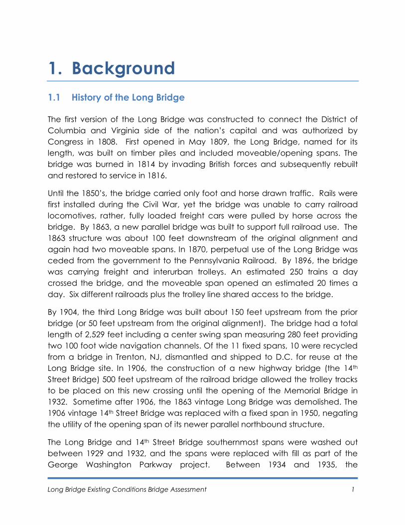
The current Long Bridge is comprised of 22 through girder spans and a double
span swing truss for a total of 24 spans over the Potomac River. It contains
elements of the 1904 bridge (the swing span and twelve piers) and of the 1942
bridge (the girder spans and eleven piers). Long Bridge carries two tracks with a
width of 36’-6” (measured between the centerline of the girders), but narrows
down to 28’-8” at the swing trusses. There is no reserve width to add additional
tracks. The vertical clearance is limited to 21’ at the swing trusses (measured
from the top of the track to the bottom of lateral bracing). Figure 1 shows
several of the through girder “approach spans” as well as the main swing span
truss over the navigation channel.
Figure 1 – Existing Through Girder and Truss Swing Spans
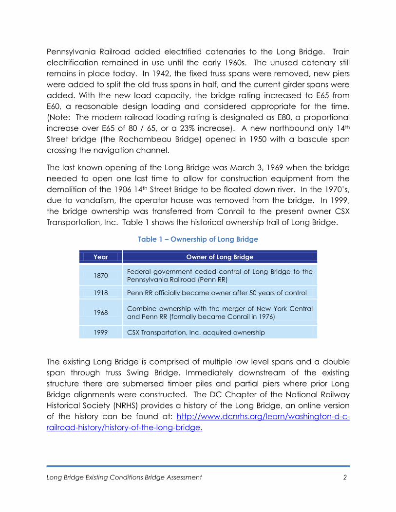
The through girder spans vary from 85 – 108
feet in length while the truss span measures
280 feet in total length and provides two
100 foot wide navigation channels. Note
that there is an additional two span bridge
that crosses the tidal basin between
Potomac Island and the District of
Columbia as shown in Figure 2.
Figure 2 - Tidal Basin Spans
Long Bridge Existing Conditions Bridge Assessment 4
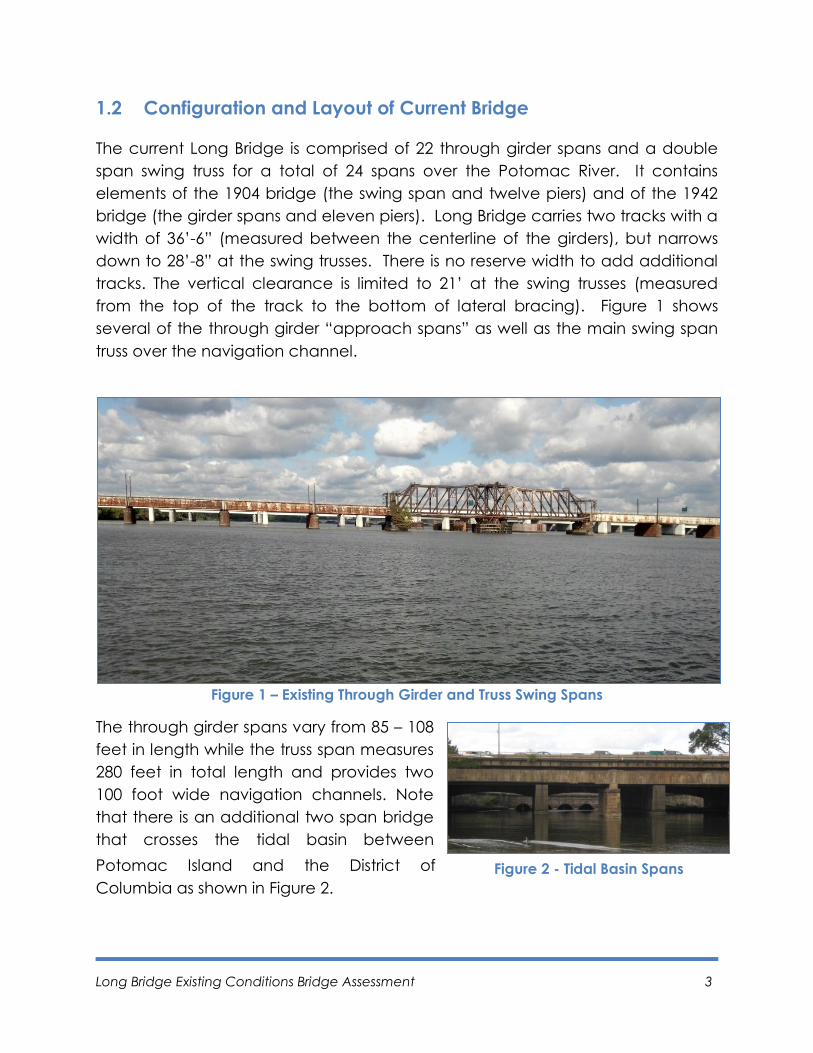
This additional two span bridge is included in the existing conditions assessment.
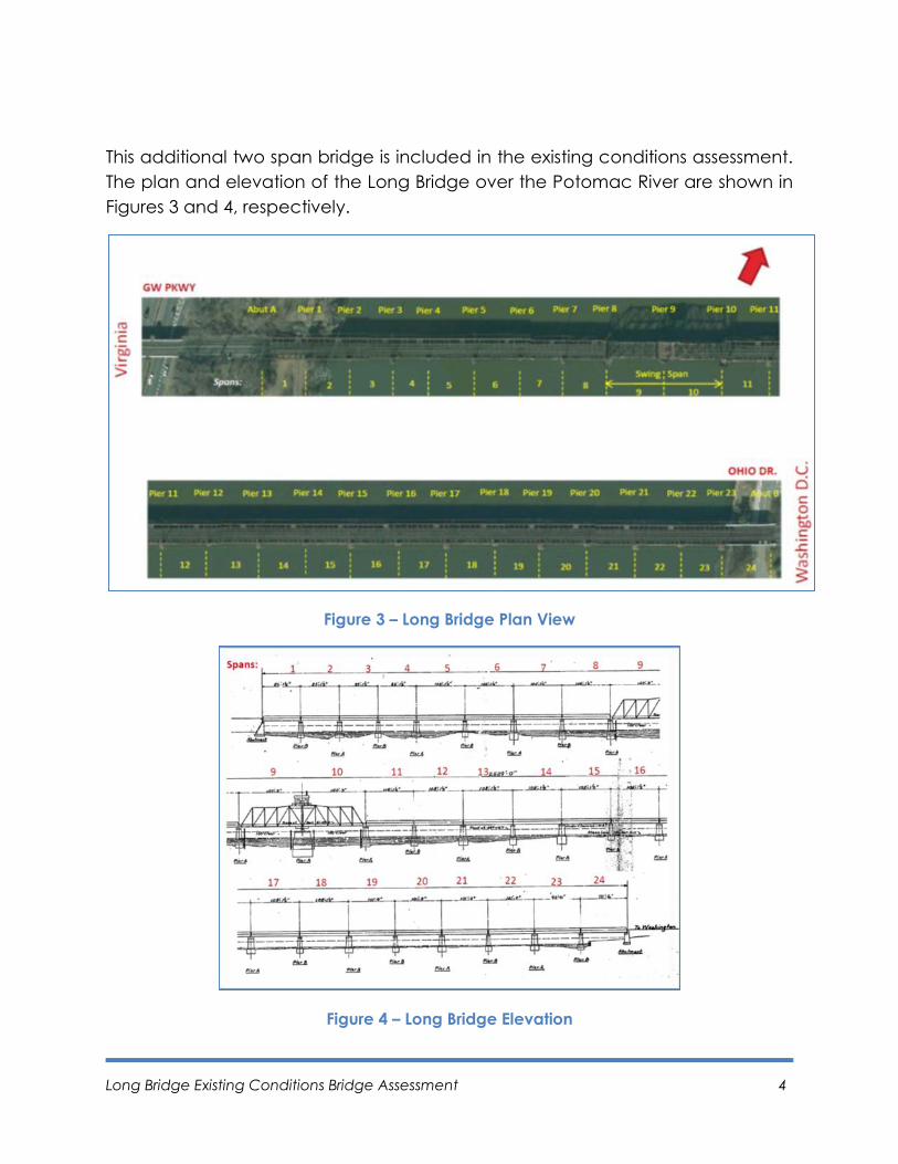
The plan and elevation of the Long Bridge over the Potomac River are shown in
Figures 3 and 4, respectively.
Figure 3 – Long Bridge Plan View
Figure 4 – Long Bridge Elevation
Long Bridge Existing Conditions Bridge Assessment 5
1.3 Through Girder Spans
The through girder spans on Long Bridge are typical of railroad bridge
construction. A through girder type bridge is used when the objective is to
minimize the bridge clearance. The use of through girder bridge and minimizing
bridge clearance is advantageous on the Potomac River to maintain the view
shed above the bridge to the monumental core of the District of Columbia. As
opposed to a typical highway bridge where the main supporting beams are
underneath the riding surface, a through girder supports the riding surface from
the bottom of the beams and the traffic passes through the bridge. The majority
of the beams are located above and adjacent to the traffic. This results in the
structure remaining largely above and outside the navigation window.
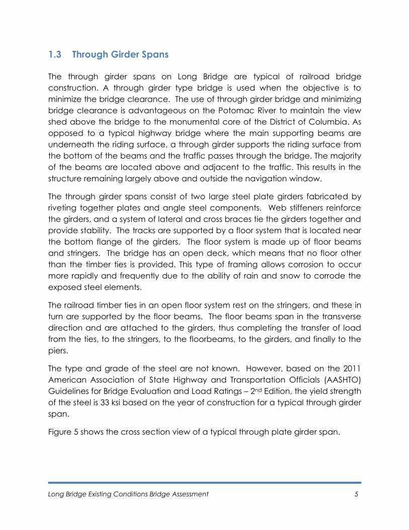
The through girder spans consist of two large steel plate girders fabricated by
riveting together plates and angle steel components. Web stiffeners reinforce
the girders, and a system of lateral and cross braces tie the girders together and
provide stability. The tracks are supported by a floor system that is located near
the bottom flange of the girders. The floor system is made up of floor beams
and stringers. The bridge has an open deck, which means that no floor other
than the timber ties is provided. This type of framing allows corrosion to occur
more rapidly and frequently due to the ability of rain and snow to corrode the
exposed steel elements.
The railroad timber ties in an open floor system rest on the stringers, and these in
turn are supported by the floor beams. The floor beams span in the transverse
direction and are attached to the girders, thus completing the transfer of load
from the ties, to the stringers, to the floorbeams, to the girders, and finally to the
piers.
The type and grade of the steel are not known. However, based on the 2011
American Association of State Highway and Transportation Officials (AASHTO)
Guidelines for Bridge Evaluation and Load Ratings – 2nd Edition, the yield strength
of the steel is 33 ksi based on the year of construction for a typical through girder
span.
Figure 5 shows the cross section view of a typical through plate girder span.
Long Bridge Existing Conditions Bridge Assessment 6
Figure 5 – Through Girder Span Profile, Soffit and Cross Section
1.4 Swing Truss Spans
The Long Bridge swing spans utilize two through trusses as the primary members
of the superstructure. The through trusses are constructed of steel. The
individual components of the trusses are sections built up from plates and
angled steel. Rivets are used to connect the truss components. A truss is simply
an assembly of triangular steel panels connected together at the intersection of
the members and sized according to the span and loading demands. The
perimeter members of a truss consist of a top chord, bottom chord, and end
posts. The interior members of the truss that completes the triangular
construction consist of diagonals, intermediate posts, and hangers. These
members are connected to each other with gusset plates. This connection
happens at what are called the panel points of the truss.
Like the through girder spans, the track is supported by a floor system, made up
of floor beams and stringers. The track rests on ties and then the stringers; the
stringers are framed into the floor beams. The floor beams span laterally and are
attached to the trusses at panel points. The truss is laterally braced by sway
bracing, top laterals, and bottom laterals.
Through
girder
Floorbeam
Knee Brace
Timber tie
Stringer
Long Bridge Existing Conditions Bridge Assessment 7
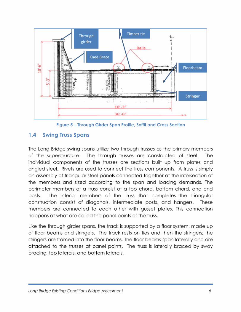
The type and grade of the steel is not known. However, based on the 2011
AASHTO Guidelines for Bridge Evaluation and Load Ratings - 2nd Edition, the yield
strength of the steel is 26 ksi based on the year of construction for a typical truss
span.
Figure 6 below shows the profile and soffit of the Long Bridge through truss span.
Figure 6 – Through Truss Span and Soffit
The double span swing truss is designed to be supported solely on the pier at its
center when the end supports have been released. It can be thought of as a
balanced seesaw as it is opening and closing. It is equipped to be turned in a
horizontal plane once it is released from the end supports in order to open the
navigable waterway. When closed in the normal traffic position, lifts are inserted
under the tips of the cantilevers, supporting the span at the center pier and
resting on two end piers.
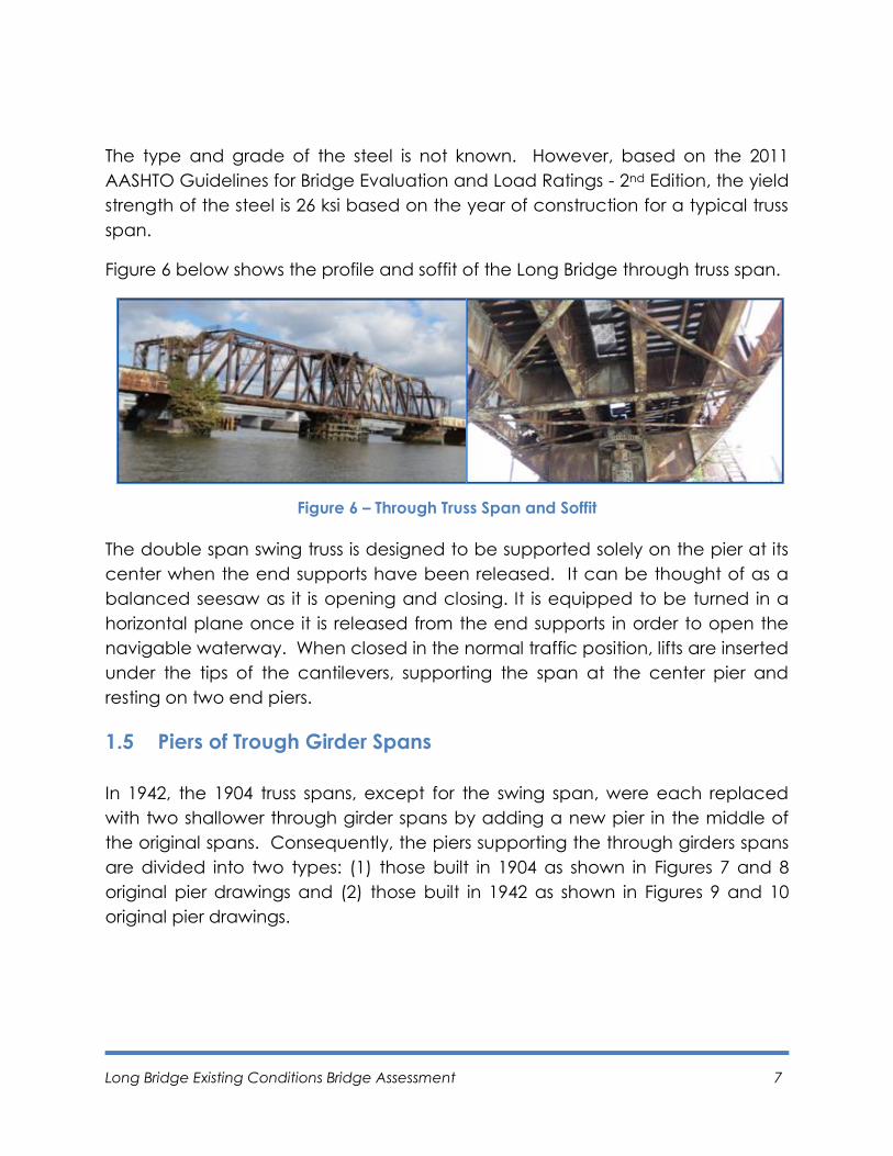
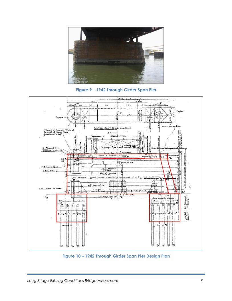
1.5 Piers of Trough Girder Spans
In 1942, the 1904 truss spans, except for the swing span, were each replaced
with two shallower through girder spans by adding a new pier in the middle of
the original spans. Consequently, the piers supporting the through girders spans
are divided into two types: (1) those built in 1904 as shown in Figures 7 and 8
original pier drawings and (2) those built in 1942 as shown in Figures 9 and 10
original pier drawings.

Long Bridge Existing Conditions Bridge Assessment 8
Figure 8 – 1904 Through Girder Span Pier Design Plan
Figure 7 – 1904 Through Girder Span Pier
Long Bridge Existing Conditions Bridge Assessment 9
Figure 9 – 1942 Through Girder Span Pier
Figure 10 – 1942 Through Girder Span Pier Design Plan
Long Bridge Existing Conditions Bridge Assessment 10
Both types of piers were constructed of concrete with a facing of cut stones.
Stone masonry facing presents a pleasing appearance and offers good
resistance to the abrasion of the flowing river and protection against impact
from floating debris. The stone facing is tied to the concrete by the use of steel
anchor rods.
The piers are supported on piles that are below mud-level. Steel bearing piles
are used in the 1942 piers and timber piles in the 1904 piers.
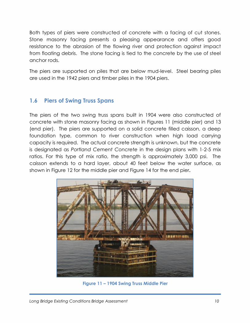
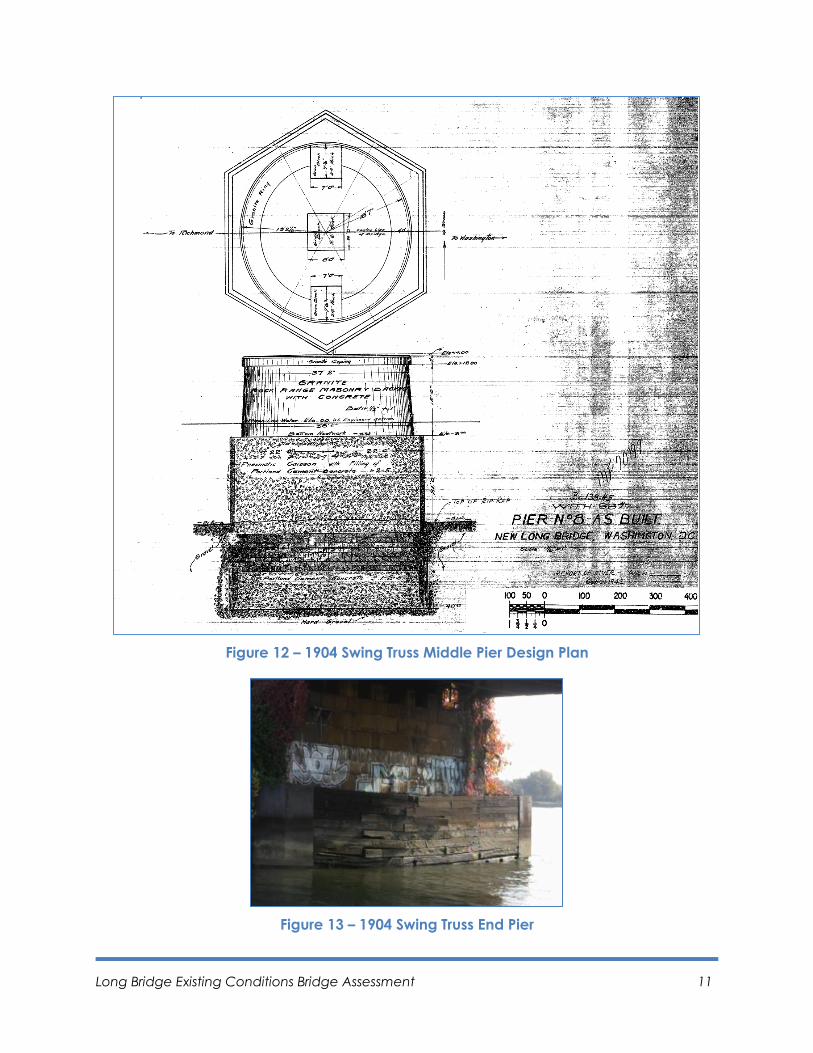
1.6 Piers of Swing Truss Spans
The piers of the two swing truss spans built in 1904 were also constructed of
concrete with stone masonry facing as shown in Figures 11 (middle pier) and 13
(end pier). The piers are supported on a solid concrete filled caisson, a deep
foundation type, common to river construction when high load carrying
capacity is required. The actual concrete strength is unknown, but the concrete
is designated as Portland Cement Concrete in the design plans with 1-2-5 mix
ratios. For this type of mix ratio, the strength is approximately 3,000 psi. The
caisson extends to a hard layer, about 40 feet below the water surface, as
shown in Figure 12 for the middle pier and Figure 14 for the end pier.
Figure 11 – 1904 Swing Truss Middle Pier
Long Bridge Existing Conditions Bridge Assessment 11
Figure 12 – 1904 Swing Truss Middle Pier Design Plan
Figure 13 – 1904 Swing Truss End Pier

Long Bridge Existing Conditions Bridge Assessment 12
Figure 14 – 1904 Swing Truss End Pier Design Plan
1.7 Potomac River Hydrology
Washington, D.C. (District of Columbia) is located within the Chesapeake Bay
drainage basin on the dividing line between the Piedmont and Coastal
province. The topography within the District of Columbia ranges in elevation
from sea level along the tidal portions of the Anacostia and Potomac Rivers to
an elevation as high as 414 feet North American Vertical Datum of 1988
(NAVD88) at Tenleytown. Interstream ridges are highest in the part of the
Piedmont within the northwest part of the city. These ridges descend gradually
to the coastal plains to the south and east, where elevations rarely exceed 230
feet NAVD88. Average annual precipitation in the District of Columbia is about
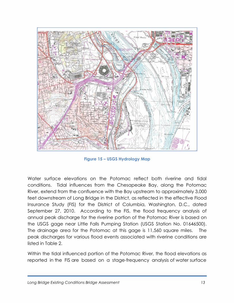
43 inches with precipitation fairly well distributed throughout the year. Figure 15
shows the United States Geological Survey (USGS) hydrology map.
Long Bridge Existing Conditions Bridge Assessment 13
Figure 15 – USGS Hydrology Map
Water surface elevations on the Potomac reflect both riverine and tidal
conditions. Tidal influences from the Chesapeake Bay, along the Potomac
River, extend from the confluence with the Bay upstream to approximately 3,000
feet downstream of Long Bridge in the District, as reflected in the effective Flood
Insurance Study (FIS) for the District of Columbia, Washington, D.C., dated
September 27, 2010. According to the FIS, the flood frequency analysis of
annual peak discharge for the riverine portion of the Potomac River is based on
the USGS gage near Little Falls Pumping Station (USGS Station No. 01646500).
The drainage area for the Potomac at this gage is 11,560 square miles. The
peak discharges for various flood events associated with riverine conditions are
listed in Table 2.
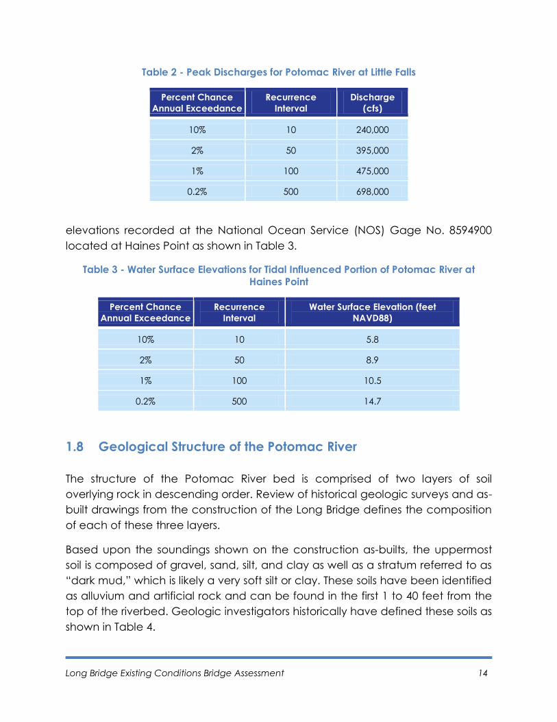
Within the tidal influenced portion of the Potomac River, the flood elevations as
reported in the FIS are based on a stage-frequency analysis of water surface
Long Bridge Existing Conditions Bridge Assessment 14
Table 2 - Peak Discharges for Potomac River at Little Falls
Percent Chance
Annual Exceedance
Recurrence
Interval
Discharge
(cfs)
10% 10 240,000
2% 50 395,000
1% 100 475,000
0.2% 500 698,000
elevations recorded at the National Ocean Service (NOS) Gage No. 8594900
located at Haines Point as shown in Table 3.
Table 3 - Water Surface Elevations for Tidal Influenced Portion of Potomac River at
Haines Point
Percent Chance
Annual Exceedance
Recurrence
Interval
Water Surface Elevation (feet
NAVD88)
10% 10 5.8
2% 50 8.9
1% 100 10.5
0.2% 500 14.7
1.8 Geological Structure of the Potomac River
The structure of the Potomac River bed is comprised of two layers of soil
overlying rock in descending order. Review of historical geologic surveys and as-
built drawings from the construction of the Long Bridge defines the composition
of each of these three layers.
Based upon the soundings shown on the construction as-builts, the uppermost
soil is composed of gravel, sand, silt, and clay as well as a stratum referred to as
“dark mud,” which is likely a very soft silt or clay. These soils have been identified
as alluvium and artificial rock and can be found in the first 1 to 40 feet from the
top of the riverbed. Geologic investigators historically have defined these soils as
shown in Table 4.
Long Bridge Existing Conditions Bridge Assessment 15
Table 4 - Alluvium and Fill Soils
Source River Bed Description
Fleming et al. (1994)
Along the edges of the river is primarily artificial fill. Within
the river itself, the soil is composed of gray to gray-brown
gravel, sand, silt, and clay derived from upgradient terrace,
colluvium, saprolite, and fresh crystalline rock deposits –
referred to as the Holocene Age Q1 Formation.
Froelich & Hack (1975)
This stratum is referred to as alluvial gravel, sand, silt, and
clay with thicknesses ranging from a veneer to 25 feet or
more, also intermixed with artificial fill, mainly river
dredgings, along edges of the river.
Johnston (1958)
Johnston refers to this material as the Pamlico Formation
and Recent alluvium, described as fine sandy loams, sands,
and clays, and to a limited extent, gravels.
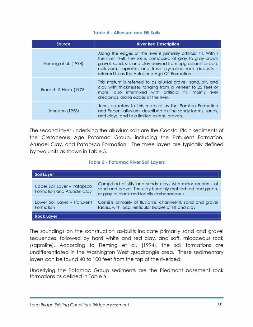
The second layer underlying the alluvium soils are the Coastal Plain sediments of
the Cretaceous Age Potomac Group, including the Patuxent Formation,
Arundel Clay, and Patapsco Formation. The three layers are typically defined
by two units as shown in Table 5.
Table 5 - Potomac River Soil Layers
Soil Layer
Upper Soil Layer – Patapsco
Formation and Arundel Clay
Comprised of silty and sandy clays with minor amounts of
sand and gravel. The clay is mainly mottled red and green,
or gray to black and locally carbonaceous.
Lower Soil Layer – Patuxent
Formation
Consists primarily of fluviatile, channel-fill, sand and gravel
facies, with local lenticular bodies of silt and clay.
Rock Layer
The soundings on the construction as-builts indicate primarily sand and gravel
sequences, followed by hard white and red clay, and soft, micaceous rock
(saprolite). According to Fleming et al. (1994), the soil formations are
undifferentiated in the Washington West quadrangle area. These sedimentary
layers can be found 40 to 100 feet from the top of the riverbed.
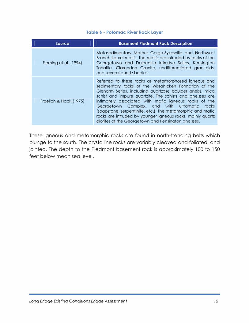
Underlying the Potomac Group sediments are the Piedmont basement rock
formations as defined in Table 6.
Long Bridge Existing Conditions Bridge Assessment 16
Table 6 - Potomac River Rock Layer
Source Basement Piedmont Rock Description
Fleming et al. (1994)
Metasedimentary Mather Gorge-Sykesville and Northwest
Branch-Laurel motifs. The motifs are intruded by rocks of the
Georgetown and Dalecarlia Intrusive Suites, Kensington
Tonalite, Clarendon Granite, undifferentiated granitoids,
and several quartz bodies.
Froelich & Hack (1975)
Referred to these rocks as metamorphosed igneous and
sedimentary rocks of the Wissahicken Formation of the
Glenarm Series, including quartzose boulder gneiss, mica
schist and impure quartzite. The schists and gneisses are
intimately associated with mafic igneous rocks of the
Georgetown Complex, and with ultramafic rocks
(soapstone, serpentinite, etc.). The metamorphic and mafic
rocks are intruded by younger igneous rocks, mainly quartz
diorites of the Georgetown and Kensington gneisses.
These igneous and metamorphic rocks are found in north-trending belts which
plunge to the south. The crystalline rocks are variably cleaved and foliated, and
jointed. The depth to the Piedmont basement rock is approximately 100 to 150
feet below mean sea level.

Long Bridge Existing Conditions Bridge Assessment 17
2. Survey Preparation
2.1 Assessment Objective
The visual assessment or survey is a precursor to a formal inspection that would
include a hands-on inspection of each component of the bridge to gather
information needed for an in-depth condition and load rating evaluation. The
objectives of the visual survey were: (1) to gather as much information as
possible without the ability to fully access the bridge superstructure; (2) to
evaluate the condition and repair needs of the bridge; and (3) to better
understand access issues, conditions, and to understand how these would
influence a more formal inspection. The formal inspection can be used to
identify additional needed repairs and better facilitate the ability to estimate
associated repair costs. The decision is pending to complete a formal
inspection of Long Bridge.
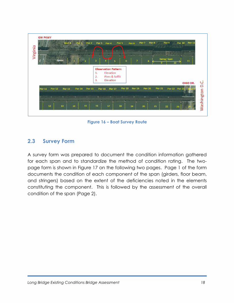
2.2 Assessment Procedure
The visual survey was a ride-by survey performed from a boat and was an
opportunity to partially assess the structure. A portion of the survey route is
shown in Figure 16 and provides an example of the route followed to assess the
individual elements of each span and pier. Each span was assessed in a similar
fashion. The route typically weaved in and out of each span so that an
overview could be conducted. Each span of the bridge was observed from the
boat in the following order: (1) upstream elevation, (2) soffit or underside view,
(3) right pier, (4) left pier and (5) downstream elevation. Due to the nature of
the observation, certain areas of the bridge, such as the deck, interior faces of
the girders or truss members, and the underwater piers and foundations could
not be observed.
Long Bridge Existing Conditions Bridge Assessment 18
Figure 16 – Boat Survey Route
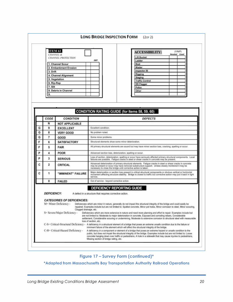
2.3 Survey Form
A survey form was prepared to document the condition information gathered
for each span and to standardize the method of condition rating. The two-
page form is shown in Figure 17 on the following two pages. Page 1 of the form
documents the condition of each component of the span (girders, floor beam,
and stringers) based on the extent of the deficiencies noted in the elements
constituting the component. This is followed by the assessment of the overall
condition of the span (Page 2).

Long Bridge Existing Conditions Bridge Assessment 19
Figure 17 – Survey Form*
*Adapted from Massachusetts Bay Transportation Authority Railroad Operations
Long Bridge Existing Conditions Bridge Assessment 20
Figure 17 – Survey Form (continued)*
*Adapted from Massachusetts Bay Transportation Authority Railroad Operations
Long Bridge Existing Conditions Bridge Assessment 21
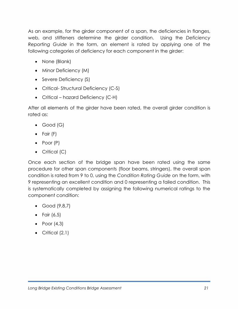
As an example, for the girder component of a span, the deficiencies in flanges,
web, and stiffeners determine the girder condition. Using the Deficiency
Reporting Guide in the form, an element is rated by applying one of the
following categories of deficiency for each component in the girder:
None (Blank)
Minor Deficiency (M)
Severe Deficiency (S)
Critical- Structural Deficiency (C-S)
Critical – hazard Deficiency (C-H)
After all elements of the girder have been rated, the overall girder condition is
rated as:
Good (G)
Fair (F)
Poor (P)
Critical (C)
Once each section of the bridge span have been rated using the same
procedure for other span components (floor beams, stringers), the overall span
condition is rated from 9 to 0, using the Condition Rating Guide on the form, with
9 representing an excellent condition and 0 representing a failed condition. This
is systematically completed by assigning the following numerical ratings to the
component condition:
Good (9,8,7)
Fair (6,5)
Poor (4,3)
Critical (2,1)

Page left blank intentionally.
Long Bridge Existing Conditions Bridge Assessment 22
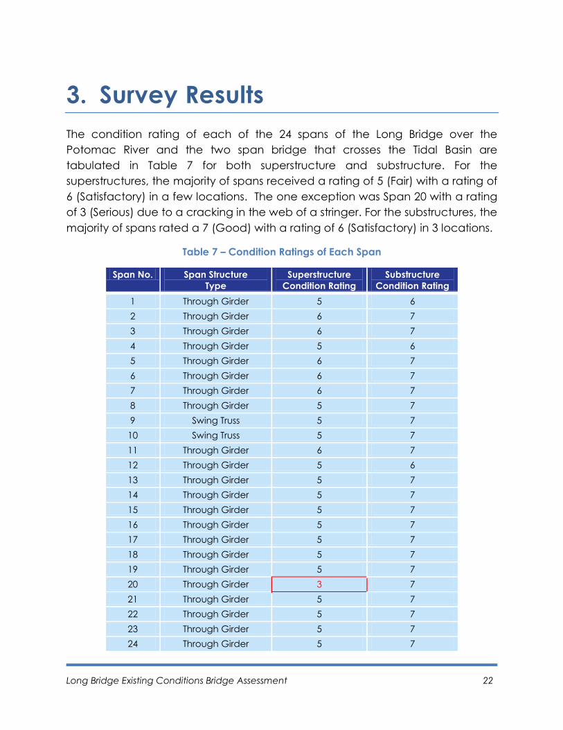
3. Survey Results
The condition rating of each of the 24 spans of the Long Bridge over the
Potomac River and the two span bridge that crosses the Tidal Basin are
tabulated in Table 7 for both superstructure and substructure. For the
superstructures, the majority of spans received a rating of 5 (Fair) with a rating of
6 (Satisfactory) in a few locations. The one exception was Span 20 with a rating
of 3 (Serious) due to a cracking in the web of a stringer. For the substructures, the
majority of spans rated a 7 (Good) with a rating of 6 (Satisfactory) in 3 locations.
Table 7 – Condition Ratings of Each Span
Span No. Span Structure
Type
Superstructure
Condition Rating
Substructure
Condition Rating
1 Through Girder 5 6
2 Through Girder 6 7
3 Through Girder 6 7
4 Through Girder 5 6
5 Through Girder 6 7
6 Through Girder 6 7
7 Through Girder 6 7
8 Through Girder 5 7
9 Swing Truss 5 7
10 Swing Truss 5 7
11 Through Girder 6 7
12 Through Girder 5 6
13 Through Girder 5 7
14 Through Girder 5 7
15 Through Girder 5 7
16 Through Girder 5 7
17 Through Girder 5 7
18 Through Girder 5 7
19 Through Girder 5 7
20 Through Girder 3 7
21 Through Girder 5 7
22 Through Girder 5 7
23 Through Girder 5 7
24 Through Girder 5 7
Long Bridge Existing Conditions Bridge Assessment 23
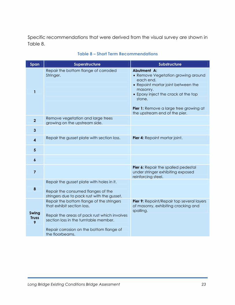
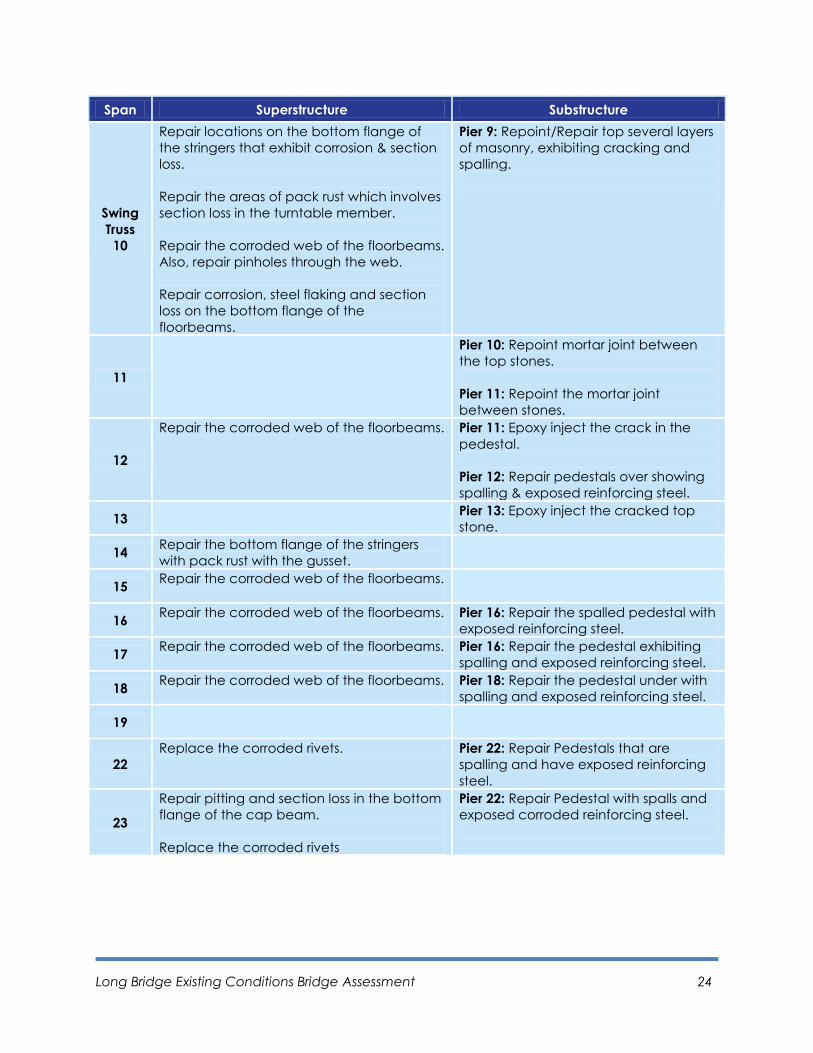
Specific recommendations that were derived from the visual survey are shown in
Table 8.
Table 8 – Short Term Recommendations
Span Superstructure Substructure
1
Repair the bottom flange of corroded
Stringer.
Abutment A:
Remove Vegetation growing around
each end.
Repoint mortar joint between the
masonry.
Epoxy inject the crack at the top
stone.
Pier 1: Remove a large tree growing at
the upstream end of the pier.
2 Remove vegetation and large trees
growing on the upstream side.
3
4 Repair the gusset plate with section loss.
Pier 4: Repoint mortar joint.
5
6
7
Pier 6: Repair the spalled pedestal
under stringer exhibiting exposed
reinforcing steel.
8
Repair the gusset plate with holes in it.
Repair the consumed flanges of the
stringers due to pack rust with the gusset.
Swing
Truss
9
Repair the bottom flange of the stringers
that exhibit section loss.
Repair the areas of pack rust which involves
section loss in the turntable member.
Repair corrosion on the bottom flange of
the floorbeams.
Pier 9: Repoint/Repair top several layers
of masonry, exhibiting cracking and
spalling.
Long Bridge Existing Conditions Bridge Assessment 24
Span Superstructure Substructure
Swing
Truss
10
Repair locations on the bottom flange of
the stringers that exhibit corrosion & section
loss.
Repair the areas of pack rust which involves
section loss in the turntable member.
Repair the corroded web of the floorbeams.
Also, repair pinholes through the web.
Repair corrosion, steel flaking and section
loss on the bottom flange of the
floorbeams.
Pier 9: Repoint/Repair top several layers
of masonry, exhibiting cracking and
spalling.
11
Pier 10: Repoint mortar joint between
the top stones.
Pier 11: Repoint the mortar joint
between stones.
12
Repair the corroded web of the floorbeams. Pier 11: Epoxy inject the crack in the
pedestal.
Pier 12: Repair pedestals over showing
spalling & exposed reinforcing steel.
13 Pier 13: Epoxy inject the cracked top
stone.
14 Repair the bottom flange of the stringers
with pack rust with the gusset.
15 Repair the corroded web of the floorbeams.
16 Repair the corroded web of the floorbeams.
Pier 16: Repair the spalled pedestal with
exposed reinforcing steel.
17 Repair the corroded web of the floorbeams. Pier 16: Repair the pedestal exhibiting
spalling and exposed reinforcing steel.
18 Repair the corroded web of the floorbeams.
Pier 18: Repair the pedestal under with
spalling and exposed reinforcing steel.
19
22
Replace the corroded rivets. Pier 22: Repair Pedestals that are
spalling and have exposed reinforcing
steel.
23
Repair pitting and section loss in the bottom
flange of the cap beam.
Replace the corroded rivets
Pier 22: Repair Pedestal with spalls and
exposed corroded reinforcing steel.
Long Bridge Existing Conditions Bridge Assessment 25
Span Superstructure Substructure
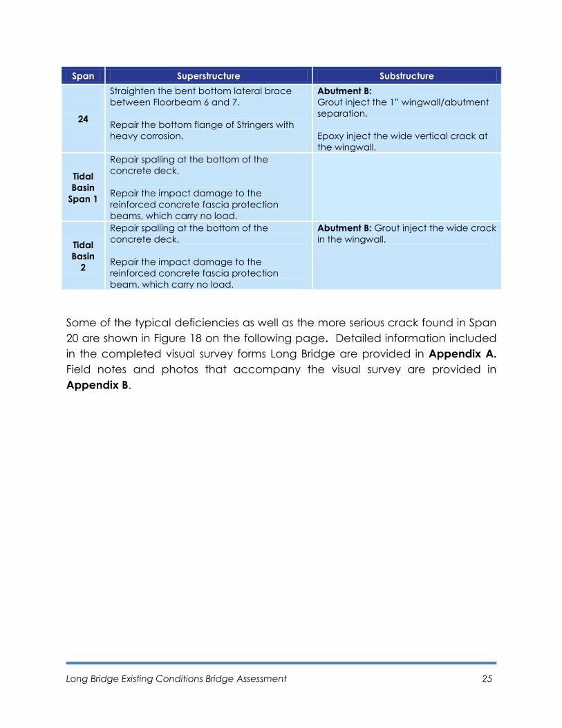
24
Straighten the bent bottom lateral brace
between Floorbeam 6 and 7.
Repair the bottom flange of Stringers with
heavy corrosion.
Abutment B:
Grout inject the 1” wingwall/abutment
separation.
Epoxy inject the wide vertical crack at
the wingwall.
Tidal
Basin
Span 1
Repair spalling at the bottom of the
concrete deck.
Repair the impact damage to the
reinforced concrete fascia protection
beams, which carry no load.
Tidal
Basin
2
Repair spalling at the bottom of the
concrete deck.
Repair the impact damage to the
reinforced concrete fascia protection
beam, which carry no load.
Abutment B: Grout inject the wide crack
in the wingwall.
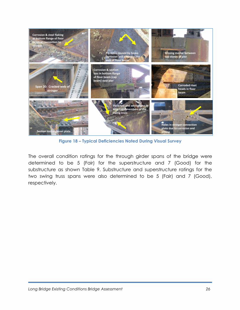
Some of the typical deficiencies as well as the more serious crack found in Span
20 are shown in Figure 18 on the following page. Detailed information included
in the completed visual survey forms Long Bridge are provided in Appendix A.
Field notes and photos that accompany the visual survey are provided in
Appendix B.
Long Bridge Existing Conditions Bridge Assessment 26
Figure 18 – Typical Deficiencies Noted During Visual Survey
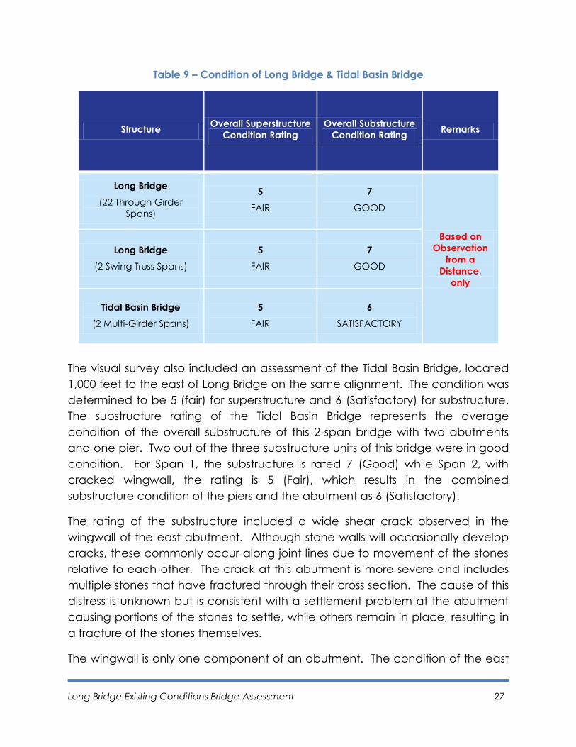
The overall condition ratings for the through girder spans of the bridge were
determined to be 5 (Fair) for the superstructure and 7 (Good) for the
substructure as shown Table 9. Substructure and superstructure ratings for the
two swing truss spans were also determined to be 5 (Fair) and 7 (Good),
respectively.
Tidal Basin Br.
Corrosion & steel flaking at bottom flange of floor beam at connection to stringer
Pin holes caused by heavy corrosion and pitting in the web of floor beam
Missing mortar between top stones of pier
Span 20: Cracked web of stringer
Corrosion & section loss in bottom flange of floor beam (cap beam) over pier
Corroded rivet heads in floor beam
Section loss in gusset plate
Pack rust and section loss in turn table members of the swing truss
Holes in stringer connection plate due to corrosion and pitting
Long Bridge Existing Conditions Bridge Assessment 27
Table 9 – Condition of Long Bridge & Tidal Basin Bridge
Structure Overall Superstructure
Condition Rating
Overall Substructure
Condition Rating Remarks
Long Bridge
(22 Through Girder
Spans)
5
FAIR
7
GOOD
Based on
Observation
from a
Distance,
only
Long Bridge
(2 Swing Truss Spans)
5
FAIR
7
GOOD
Tidal Basin Bridge
(2 Multi-Girder Spans)
5
FAIR
6
SATISFACTORY
The visual survey also included an assessment of the Tidal Basin Bridge, located
1,000 feet to the east of Long Bridge on the same alignment. The condition was
determined to be 5 (fair) for superstructure and 6 (Satisfactory) for substructure.
The substructure rating of the Tidal Basin Bridge represents the average
condition of the overall substructure of this 2-span bridge with two abutments
and one pier. Two out of the three substructure units of this bridge were in good
condition. For Span 1, the substructure is rated 7 (Good) while Span 2, with
cracked wingwall, the rating is 5 (Fair), which results in the combined
substructure condition of the piers and the abutment as 6 (Satisfactory).
The rating of the substructure included a wide shear crack observed in the
wingwall of the east abutment. Although stone walls will occasionally develop
cracks, these commonly occur along joint lines due to movement of the stones
relative to each other. The crack at this abutment is more severe and includes
multiple stones that have fractured through their cross section. The cause of this
distress is unknown but is consistent with a settlement problem at the abutment
causing portions of the stones to settle, while others remain in place, resulting in
a fracture of the stones themselves.
The wingwall is only one component of an abutment. The condition of the east
Long Bridge Existing Conditions Bridge Assessment 28
wingwall is reported as 4 (Poor) with a deficiency designated as 3 (Serious) due
to the cracking. The other components of the same abutment are in relatively
good condition. The backwall and stem breast wall are in 5 (Fair) condition and
the seats are in 7 (Good) condition.
The Tidal Basin Bridge includes a crash protection concrete façade on the
exterior of the bridge. The concrete façade is not in good condition with
noticeable cracking and exposed rebar. The concrete façade is not a structural
element of the bridge.
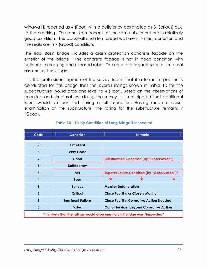
It is the professional opinion of the survey team, that if a formal inspection is
conducted for this bridge that the overall ratings shown in Table 10 for the
superstructure would drop one level to 4 (Poor). Based on the observations of
corrosion and structural loss during the survey, it is anticipated that additional
issues would be identified during a full inspection. Having made a closer
examination of the substructure, the rating for the substructure remains 7
(Good).
Table 10 – Likely Condition of Long Bridge if Inspected
Code Condition Remarks
9 Excellent
8 Very Good
7 Good Substructure Condition (by “Observation”)
6 Satisfactory
5 Fair Superstructure Condition (by “Observation”)*
4 Poor
3 Serious Monitor Deterioration
2 Critical Close Facility, or Closely Monitor
1 Imminent Failure Close Facility, Corrective Action Needed
0 Failed Out of Service, beyond Corrective Action
*It is likely that the ratings would drop one notch if bridge was “inspected”

Page left blank intentionally.
Long Bridge Existing Conditions Bridge Assessment 29
4. Recommendations
4.1 Short-Term Serviceability and Costs
Based on the results of the visual survey performed for this study, it is
recommended that the following short-term repairs for elements identified in
Chapter 3 will be needed:
Steel section loss due to corrosion
Steel cracking due to fatigue
The nature of these repairs can only be fully determined by a formal inspection,
which requires permission to access the bridge from the CSX Corporation. The
information obtained from a formal inspection would be sufficient for
preparation of plans, specifications and estimates (PS&E) documents for the
recommended repair work or recommendations for force account work should
CSX desire to perform the work in-house or with on-call contractors. Additional
information would be needed on the magnitude and exact location of the
deterioration that requires repair. Appendix C provides the detailed scope and
associated costs for performing a formal bridge inspection.
An additional option to extend the usable life of the bridge and provide
improve the aesthetic appearance would be to paint the bridge. This would
require surface preparation to remove mill scale, rust, and the existing paint that
may increase the chance of failure and peeling of the new coating.
Contaminant containment is needed to prevent both lead and other debris
generated during surface preparation activities from entering the environment.
Typically, up to three coatings of paint are applied to the structure.
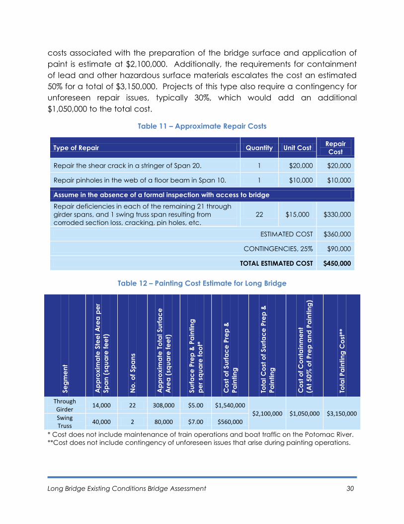
Based on the visual survey, it is estimated that the cost of bridge repair for short-
term serviceability will be approximately $450,000, as shown in Table 11. This
estimate includes a sizeable contingency that is typically set aside for
unforeseen issues that arise during repair. In this instance it represents an
estimated cost of repair for each of the 22 spans over the Potomac River and is
only an approximation.
The cost of painting the spans over the Potomac River is shown in Table 12. The
Long Bridge Existing Conditions Bridge Assessment 30
costs associated with the preparation of the bridge surface and application of
paint is estimate at $2,100,000. Additionally, the requirements for containment
of lead and other hazardous surface materials escalates the cost an estimated
50% for a total of $3,150,000. Projects of this type also require a contingency for
unforeseen repair issues, typically 30%, which would add an additional
$1,050,000 to the total cost.
Table 11 – Approximate Repair Costs
Type of Repair Quantity Unit Cost Repair
Cost
Repair the shear crack in a stringer of Span 20. 1 $20,000 $20,000
Repair pinholes in the web of a floor beam in Span 10. 1 $10,000 $10,000
Assume in the absence of a formal inspection with access to bridge
Repair deficiencies in each of the remaining 21 through
girder spans, and 1 swing truss span resulting from
corroded section loss, cracking, pin holes, etc.
22
$15,000 $330,000
ESTIMATED COST $360,000
CONTINGENCIES, 25% $90,000
TOTAL ESTIMATED COST $450,000
Table 12 – Painting Cost Estimate for Long Bridge
Se
gm
en
t
Ap
pro
xim
ate
Ste
el A
rea
pe
r
Sp
an
(sq
ua
re fe
et)
No
. o
f Sp
an
s
Ap
pro
xim
ate
To
tal Su
rfa
ce
Are
a (
squ
are
fe
et)
Su
rfa
ce
Pre
p &
Pa
intin
g
pe
r sq
ua
re fo
ot*
Co
st o
f Su
rfa
ce
Pre
p &
Pa
intin
g
Tota
l C
ost
of Su
rfa
ce
Pre
p &
Pa
intin
g
Co
st o
f C
on
tain
me
nt
(At
50
% o
f P
rep
an
d P
ain
tin
g)
Tota
l P
ain
tin
g C
ost
**
Through Girder
14,000 22 308,000 $5.00 $1,540,000
$2,100,000 $1,050,000 $3,150,000 Swing Truss
40,000 2 80,000 $7.00 $560,000
* Cost does not include maintenance of train operations and boat traffic on the Potomac River.
**Cost does not include contingency of unforeseen issues that arise during painting operations.
Long Bridge Existing Conditions Bridge Assessment 31
4.2 Load Capacity/Demand Analysis
The service life of the bridge can best be answered by determining the current
and future load capacities and load demands (this methodology assumes some
short-term repairs as described above). The load demand of a bridge refers to
the vehicle load that the structure will be subjected to while the bridge is in
service. The load capacity of a bridge is the overall ability of the bridge to carry
the imposed demand. For a satisfactory performance, the capacity must be
greater than the demand meaning that the capacity-to-demand ratio greater
than 1 (i.e. C/D > 1).
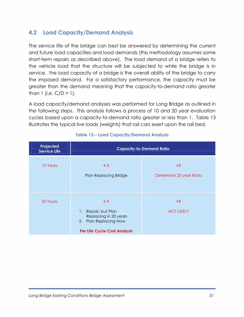
A load capacity/demand analyses was performed for Long Bridge as outlined in
the following steps. This analysis follows a process of 10 and 20 year evaluation
cycles based upon a capacity-to-demand ratio greater or less than 1. Table 13
illustrates the typical live loads (weights) that rail cars exert upon the rail bed.
Table 13 – Load Capacity/Demand Analysis
Projected
Service Life Capacity-to-Demand Ratio
10 Years
< 1
Plan Replacing Bridge
>1
Determine 20 year Ratio
20 Years
< 1
1. Repair, but Plan
Replacing in 20 years
2. Plan Replacing Now
Per Life Cycle Cost Analysis
>1
NOT LIKELY
Long Bridge Existing Conditions Bridge Assessment 32
Step 1: Determine Load Capacity
A. Determine original capacity using the sections and dimensions per the
original bridge plans.
B. Determine the current capacity due to corrosion and fatigue. Assume the
average overall steel section loss as 1/8” per current observation. Assume
higher and lower limits of section loss as 3/16” and 1/16” and evaluate the
sensitivity. Adjust the capacity for the average 1/8” section loss, if
needed, per sensitivity.
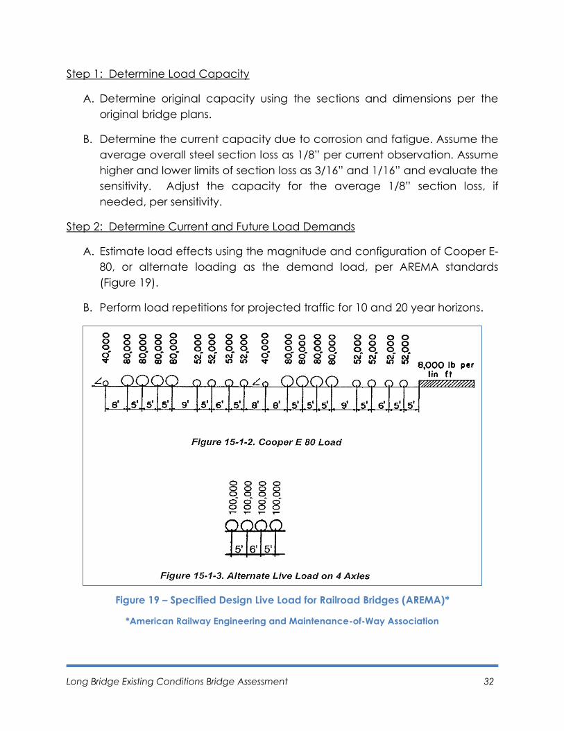
Step 2: Determine Current and Future Load Demands
A. Estimate load effects using the magnitude and configuration of Cooper E-
80, or alternate loading as the demand load, per AREMA standards
(Figure 19).
B. Perform load repetitions for projected traffic for 10 and 20 year horizons.
Figure 19 – Specified Design Live Load for Railroad Bridges (AREMA)*
*American Railway Engineering and Maintenance-of-Way Association

Long Bridge Existing Conditions Bridge Assessment 33
Step 3: Determine Capacity-to-Demand Ratio (C/D)
A. Estimate 10 year C/D ratio such that if C/D < 1, plan on replacing bridge
immediately or if C/D > 1 assess using 20 year C/D ratio.
B. Estimate 20 year C/D ratio such that if C/D < 1, perform a Life Cycle Cost
Analysis to determine the most cost-effective option of either replacing
the bridge immediately or replacing the bridge in another 10 years. For
the 20 year analysis, it is highly unlikely that the C/D ratio >1, because of
the increases load repetitions and age.
Depending upon the year and ratio, it can be determined if replacement of the
bridge is necessary. The actual load rating report is provided separately from
this document as it is a professional engineer sealed document.
4.3 Detailed Inspection Process
The execution of a detailed bridge inspection would include assessment of the
topside superstructure as well as an underwater inspection.
Topside Inspection
The topside inspection would employ visual, physical and advanced inspection
techniques to document deficiencies, identify critical deficiencies and
recommend repairs to maintain short-term serviceability. Techniques used to
perform the topside inspection include: barge with a lift, rail mounted under-
bridge inspection unit, rail mounted bucket truck and ladders or scaffolding for
bridge structure not over the Potomac River. The inspection will be primarily
visual in nature performed up-close for individual elements of the structure. In
some instances, more advanced methods may be used for inspection such as
(but not limited to) dye penetrant, magnetic particle and ultrasonic testing.
The inspection would pay specific attention to fracture critical members.
Fracture critical members are defined as steel members in tension or with a
tension element, whose failure would probably result in a portion or full bridge
collapse.
Overall management of the inspections will be the responsibility of an inspection
manager supported by a quality assurance/quality control manager, team
leaders and inspection team members. Personnel in the role of inspection
manager and team leader are required to meet the qualifications as listed in
Long Bridge Existing Conditions Bridge Assessment 34
the Code of Federal Regulations, Title 23 – Highways, Subpart G, Part 650 –
Bridges, Structures and Hydraulics.
The inspection is conducted so that at no time will inspection activities be
allowed to interrupt the flow of rail traffic. Scheduling of inspections must work
around the schedule of rail traffic operations. A flagman from CSX will be
required at all times during the inspection whether inspection activities will
directly affect rail traffic or not. Coordination with CSX will take place well in
advance of inspection activities so all parties are aware of the requirements and
needs of the inspection process. To maximize inspection time, all inspections will
be performed at night when rail operations are at a minimum. It is assumed to
expect a maximum of only four hours per night of uninterrupted inspection time.
The duration of the inspection is determined by estimating the hours needed to
inspect the truss and non-truss spans. For the two truss spans, the inspection of
the lower members, the truss and the portion at and above the ballast is
estimated at 20 hours. For the 22 non-truss spans, the inspection of the lower
members and the portion at and above the ballast is estimated at 55 hours.
Underwater Inspection
The underwater inspection is completed for all 23 submerged piers and one
submerged abutment. This is completed by a 3-person dive team consisting of a
supervising engineer and two divers. The inspection includes a Level 1 visual /
tactile inspection of the entire structure, combined with a Level II detailed
inspection with partial cleaning on 10% of the structural elements. Underwater
inspection data is collected in accordance with the National Bridge Inspection
Standards. All data is recorded by the supervising engineer and included in a
final inspection report. The duration of the underwater inspection is
approximately two weeks.
The Long Bridge detailed inspection will be a month long effort coordinated for
concurrent efforts of superstructure and underwater inspection as detailed in
Appendix C. This inspection would provide a comprehensive assessment of the
serviceable life of the Long Bridge and help shape the need for short- and long-
term recommendations for bridge enhancement or replacement.
Long Bridge Existing Conditions Bridge Assessment 35
5. Conclusions
A bridge assessment via boat access included a limited visual review of the
superstructure and substructure. It is the first step in determining the life and
serviceability of a bridge. The objective of the boat survey was to identify any
immediately observable critical issues but more so to plan a more complete
inspection. Many railroad bridges of this age (from 70 – 110 years in age)
continue to provide reliable service to their owners yet modern train weights
and the high numbers of cycles of loading have an increasing effect on their
deterioration and remaining life. This is due to a number of factors including the
conservative nature of railroad bridge design, the high loads they were
designed for when steam locomotives were common, and other factors that
allow older bridges to remain in service past their expected / projected service
life. The Long Bridge is no exception. It certainly has some short-term and long
term rehabilitation needs, some of which are defined herein and others of which
can only be determined following a more complete inspection. As to its long
term viability, that will be determined after load ratings and more detailed
inspections are complete.

Page left blank intentionally.