Embed Size (px)
Citation preview

1

3
Magnetic fieldsElectric fields
1 2
24r
Q Q
rF a
24
o RIdld
R
aB
.encQ D dS .encI H dl (V/m)
VE
(A/m)
IH
D E B H
1.
2EW D E
1.
2EW B H
Coulomb's law
Gauss’s law Ampere's law
Biot-Savart's law
4
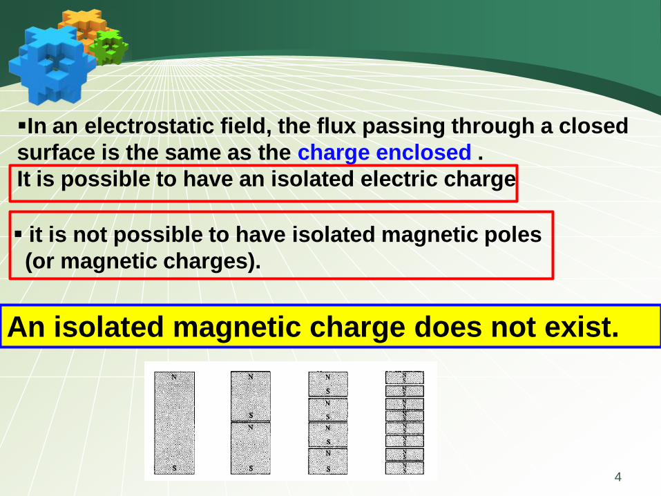
In an electrostatic field, the flux passing through a closed
surface is the same as the charge enclosed .
It is possible to have an isolated electric charge
it is not possible to have isolated magnetic poles
(or magnetic charges).
An isolated magnetic charge does not exist.

5
flux passing through a closed surface is the same as the
charge enclosed .
.D dS Q . 0B dS Gauss's law for electrostatic fields Gauss's law for magnetostatic fields
law of conservation of magnetic flux

Maxwell’s equations for static fields
enc
enc
D dS Q
B dS 0
E d L 0
H d L I
vD
B 0
E 0
H J
7
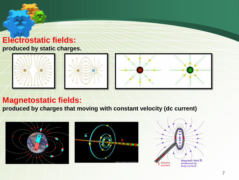
Electrostatic fields: produced by static charges.
Magnetostatic fields: produced by charges that moving with constant velocity (dc current)
8
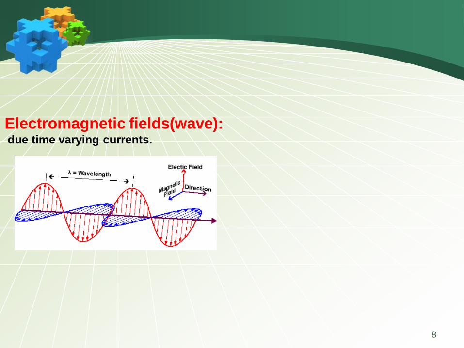
Electromagnetic fields(wave):due time varying currents.
9
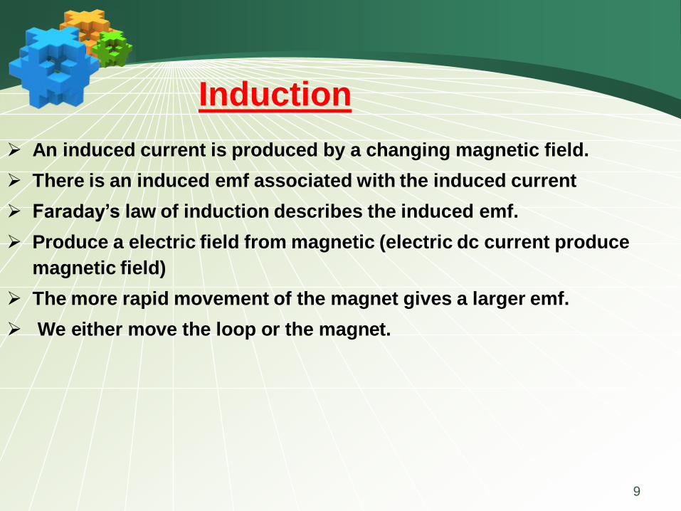
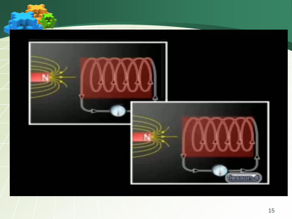
An induced current is produced by a changing magnetic field.
There is an induced emf associated with the induced current
Faraday’s law of induction describes the induced emf.
Produce a electric field from magnetic (electric dc current produce
magnetic field)
The more rapid movement of the magnet gives a larger emf.
We either move the loop or the magnet.
Induction

10
11

12
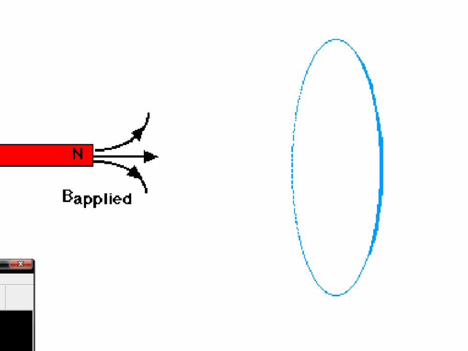
When the magnet is held stationary, there is no
deflection of the ammeter
Therefore, there is no induced current
Even though the magnet is in the loop
The magnet is moved toward or away from the loop
The ammeter deflects in the opposite direction

13
Faraday discovered that a time-varying magnetic field
would produce an electric current.
Faraday discovered that the induced emf, Vemf (in volts),
in any closed circuit is equal to the time rate of change
of the magnetic flux linkage by the circuit.
Faraday
emf
ΨV
d dN
dt dt
: linkage
- : len'z law
N:number of turn in the circuit
Ψ:flux through each turn= .
flux
B dS

14
15

16
The variation of flux with time may be caused in three ways:
1. By having a stationary loop in a time-varying B field
2. By having a time-varying loop area in a static B field
3. By having a time-varying loop area in a time-varying B field.
Ψd
dt
17
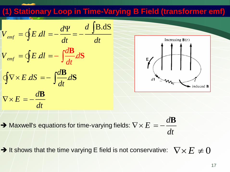
Maxwell's equations for time-varying fields:d
Edt
B
It shows that the time varying E field is not conservative: 0E
(1) Stationary Loop in Time-Varying B Field (transformer emf)
B.dSΨ.
.
. .
.
emf
emf
ddV E dl
dt dt
V E dl
dE dS d
d
dt
dE
d
ddt
t
S
B
B
S
B
18
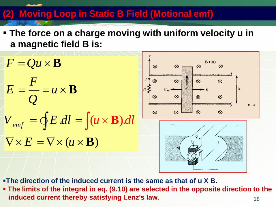
The force on a charge moving with uniform velocity u in
a magnetic field B is:
( )..
( )
emf
F Qu
FE u
Q
V E dl
E u
u dl
B
B
B
B
(2) Moving Loop in Static B Field (Motional emf)
The direction of the induced current is the same as that of u X B.
The limits of the integral in eq. (9.10) are selected in the opposite direction to the
induced current thereby satisfying Lenz's law.

19
. . ( ).emf
dV E dl d u dl
dt
BS B
Transformer motional
(3) Moving Loop in Time-Varying Field

20
Consider the loop of Figure. If B = 0.5az Wb/m2 , R = 20 Ω , l = 10 cm, and
the rod is moving with a constant velocity of 8ax m/s, find:
(a) The induced emf in the rod
(b) The current through the resistor
(c) The motional force on the rod
(d) The power dissipated by the resistor
0.1
0
2 2
(a) moving loop ,static B motional emf
( ). (8 0.5 )( ) 0.4V
0.4(b) I= 20
20
(c) F=Qu (0.1 )( 0.02) (0.5 ) 0.001 N
V (0.4)(d) P= 8
20
emf x z y
y z x
V u dl dy
mA
I
mWR
B a a a
B B a a a

21
B = 0.02t ax Wb/m2 that is, the magnetic field is time varying.
If side DC of the loop cuts the flux lines at the frequency of 50 Hz and the
loop lies in the yz-plane at time t = 0, find
(a) The induced emf at t = 1 ms
(b) The induced current at t = 3 ms
0.03 0.04
0 0
5
: varying & loop:moving
.
0.02 0.02 (cos sin )
0.02 ( sin ) 0.02 ( sin )
0.02 ( sin )(0.03)(0.04) 2.4 10 sin
emf
x
z
B time
dV
dt
B dS
dS d dz
B t t
t d dz t d dz
t t
a
a
Method( :
a
1)
a

22
5 5
5 5
5 5
t=0 , ( )2
( 0) 0 , 2 2
2.4 10 sin( ) 2.4 10 cos( )2
( 2.4 10 )cos( ) ( 2.4 10 )( )( sin )
= 2.4 10 cos( ) 2.4 10 si
dw wt A
dt
At yz plane
t A wt
t wt t wt
dwt t w wt
dt
wt tw
5
5
5
n( )
2.4 10 cos( ) sin( ) V
( 1 ) 2.4 10 cos(100 0.001) (100 0.001)sin(100 0.001) =20.49 V
( 3 ) 2.4 10 cos(100 0.003) (100 0.003)sin(100 0.003) = 4.19 V
emf
emf
emf
wt
dV wt tw wt
dt
V t ms
V t ms

23
0.03 0.04
0 0
5
5
. . ( ).
0.02 0.02 (cos sin )
0.02 0.02(cos sin )
. 0.02( sin )
0.02(sin )(0.03)(0.04) 2.4 10 sin
2.4 10
2
emf
x
x
z
dV E dl d u dl
dt
t t
d
dt
dS d dz
dd d dz
dt
BS B
B a a a
Ba a a
Method( )
S
:
a
B
5 sin( ) 2.4 10 cos( ) ..............(1)2
wt wt

24
0.03
,
0
. . ( ).
0.02 0.02 (cos sin )
0.02 (cos sin )
0.02 cos ( ) 0.02 cos
( ). ( 0.02 cos ).
emf
x
z z
emf motional z z
z
dV E dl d u dl
dt
t t
ddlu w
dt dt
u w t
w t tw
V u dl tw dz
BS B
B a a a
aa
B a a a
a a
B a a
5
5 5
5
5
( 0.02)(0.03)(0.04) cos =( 2.4 10 ) cos
( 2.4 10 ) cos ( 2.4 10 ) cos( )2
( 2.4 10 ) sin( ) .......................(2)
(1) (2)
2.4 10 cos( ) sin( ) Vemf
tw tw
tw tw wt
tw wt
V wt tw wt

25
A conducting circular loop of radius 20 cm lies in the z = 0 plane in a
magnetic field B = 10 cos 377t az mWb/m2.
Calculate the induced voltage in the loop.
3
2 0.2
0 0
2 0.2
0 0
; .
(10)(377)sin(377 ) 10
3.77sin(377 )
. 3.77sin(377 )
3.77sin(377 ) 0.473sin(377 ) V
emf
z
z
z
emf
dtransformer V d
dt
dt
dt
t
d d d
dV d t d d
dt
t d d t
BS
Ba
a
S a
BS

26
A rod of length L rotates about the z-axis with an angular velocity w. If
B = Bo az , calculate the voltage induced on the conductor.
0 0 2
( ), ( )
emf
( ).
( ). . .
in + direction intergration limits in
V2
emf
emf o z o
emf o o o
L L
B static rod moving
motional
V u dl
ddu
dt dt
V u dl B d B d
u
LV B d B d B
B
aa
B a a a a a
B a a
2
0
( ), ( ) emf
.
. 2
emf
L
o z z o o
z
B static rod moving motional
d dV N N B dS
dt dt
d d LN B d d B d B
dt dt
dS d d
a a
a
27
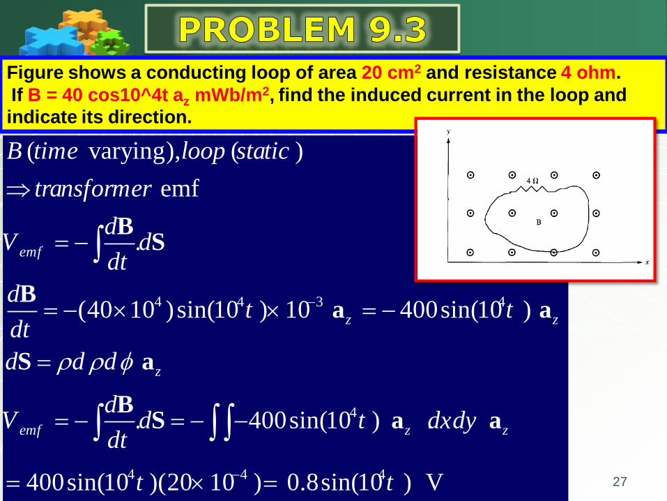
4 4 3 4
4
4 4 4
( varying), ( )
emf
.
(40 10 )sin(10 ) 10 400sin(10 )
. 400sin(10 ) .
400sin(10 )(20 10 ) 0.8sin(10 )
emf
z z
z
emf z z
B time loop static
transformer
dV d
dt
dt t
dt
d d d
dV d t dxdy
dt
t t
BS
Ba a
S a
BS a a
V
Figure shows a conducting loop of area 20 cm2 and resistance 4 ohm.
If B = 40 cos10^4t az mWb/m2, find the induced current in the loop and
indicate its direction.

28
4
1
2
( varying), ( )
emf
.
0.6
. 0.6 . 0.6 10 10 0.6 mV
0.6 (10)0.4 mV
10 5
0.6 (5)0.2 mV
10 5
emf
z
emf z z
B time loop static
transformer
dV d
dt
d
dt
dV d dxdy
dt
V
V
BS
Ba
BS a a
Figure shows a conducting loop of area 10 cm2 that lies in yz plane .
If B = -0.6t az Wb/m2, find V1 and V2
29
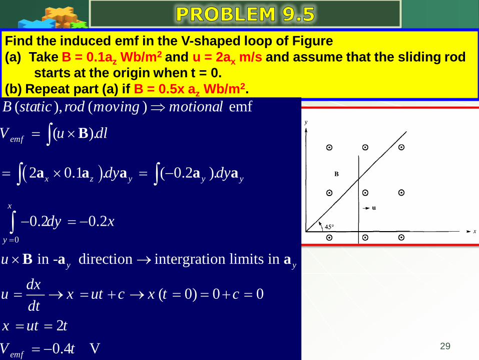
Find the induced emf in the V-shaped loop of Figure
(a) Take B = 0.1az Wb/m2 and u = 2ax m/s and assume that the sliding rod
starts at the origin when t = 0.
(b) Repeat part (a) if B = 0.5x az Wb/m2.
0
( ), ( ) emf
( ).
2 0.1 . ( 0.2 ).
0.2 0.2
in - direction intergration limits in
( 0) 0 0
2
0.4 V
emf
x z y y y
x
y
y y
emf
B static rod moving motional
V u dl
dy dy
dy x
u
dxu x ut c x t c
dt
x ut t
V t
B
a a a a a
B a a
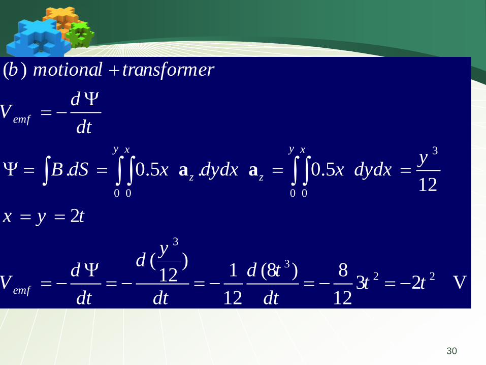
30
3
0 0 0 0
3
32 2
( )
. 0.5 . 0.5 12
2
( )1 (8 ) 812 3 2 V
12 12
emf
y yx x
z z
emf
b motional transformer
dV
dt
yB dS x dydx x dydx
x y t
yd
d d tV t t
dt dt dt
a a

31
A conducting rod moves with a constant velocity of 3az m/s parallel to a
long straight wire carrying current 15 A as in Figure . Calculate the emf
induced in the rod and state which end is at higher potential.
( ), ( ) emf
( ).
for an infinite line is:
B=2
3(3 ) ( ) ( )
2 2
3( ). ( ) .
2
in direction intergration limits in
emf
o
o oz
oemf
B static rod moving motional
V u dl
B
I
I Iu
IV u dl d
u
B
a
B a a a
B a a
B a
0.6 0.6
0.20.2
3 3 (15)ln | 9.9 V
2 2
o oemf
IV d
a