Embed Size (px)
Citation preview

Logic Manual
Standard Configuration
Configurable basic module
TALOS ®
TB - I14O3

H. ZANDER GmbH & Co. KG • Am Gut Wolf 15 • 52070 Aachen • Germany • phone +49 (0)241 9105010
Fax +49 (0)241 91050138 • [email protected] • www.zander-aachen.de 2
Logic manual TB-I14O3 - Standard Configurations
ZANDER GmbH & Co. KG
Am Gut Wolf 15
52070 Aachen, Germany
www.zander-aachen.de
Revision: F03
Engl. translation
Subject to technical modifications, no
responsibility is accepted for the accuracy of
this information.

H. ZANDER GmbH & Co. KG • Am Gut Wolf 15 • 52070 Aachen • Germany • Tel +49 (0)241 9105010
Fax +49 (0)241 91050138 • [email protected] • www.zander-aachen.de 3
Logic manual TB-I14O3 - Standard Configurations
Contents
1. About this document ...................................................................... 9
1.1. Scope ............................................................................................................ 9
1.2. Target group .................................................................................................... 9
1.3. Key to symbols ................................................................................................ 9
1.4. Additional documents ................................................................................... 10
1.5. Information about the machine manufacturer‘s documentation ................ 11
1.6. Safety function ............................................................................................. 12
2. Description of the input and output types and the logic functions ....15
2.1. Time behavior of inputs and outputs ........................................................... 15
2.1.1. Difference time ............................................................................................. 15
2.1.2. Switch-off delay ............................................................................................ 16
2.1.3. Switch-on delay ............................................................................................ 17
2.1.4. Clock signals at safety outputs O1 .. O3 ....................................................... 18
2.2. Safety inputs .................................................................................................. 19
2.2.1. Two-channel contacts with short circuit monitoring ....................................... 20
2.2.2. Two-channel contacts without short circuit monitoring .................................. 21
2.2.3. Two-channel contacts for non-contact safety switches with short circuit
monitoring , e.g. with ZANDER Safety-Switches ZCode ............................... 22
2.2.4. Two-channel contacts for non-contact safety switches without short circuit
monitoring, e.g. with ZANDER Safety-Switches ZCode ................................ 23
2.2.5. Two-channel safe input for antivalent contacts with additional test pulses .... 24
2.2.6. Two-channel safe input for antivalent contacts ............................................. 25
2.2.7. Two-channel OSSD safety input ................................................................... 26
2.2.8. One-channel contacts with short circuit monitoring ....................................... 27
2.2.9. One-channel contacts without short circuit monitoring .................................. 28
2.2.10. One-channel OSSD safety input ................................................................. 29
2.3. Group signal input ........................................................................................ 30
2.3.1. Two-channel group signal input to connect thwo TALOS TB-I14O3 ............. 30
2.4. Control inputs ................................................................................................ 31
2.4.1. Control input ................................................................................................. 31
2.4.2. Input feedback loop ...................................................................................... 32
2.4.3. Input for monitored start button ..................................................................... 33
2.5. Safety outputs ............................................................................................... 34
2.5.1. Safety outputs with pulsing ........................................................................... 34
2.5.2. Safety outputs without pulsing ...................................................................... 35

H. ZANDER GmbH & Co. KG • Am Gut Wolf 15 • 52070 Aachen • Germany • phone +49 (0)241 9105010
Fax +49 (0)241 91050138 • [email protected] • www.zander-aachen.de 4
Logic manual TB-I14O3 - Standard Configurations
2.6. Auxiliary outputs ........................................................................................... 36
2.6.1. Auxiliary outputs ........................................................................................... 36
2.6.2. Auxiliary output with increased output current .............................................. 37
2.6.3. Group signal output ...................................................................................... 37
2.7. Logic modules ............................................................................................... 38
2.7.1. AND-Link ...................................................................................................... 38
2.7.2. OR-Link ........................................................................................................ 38
2.7.3. Inverter ......................................................................................................... 38
2.7.4. Switch-on/Switch-off delay ........................................................................... 39
2.7.5. Start logic function ........................................................................................ 39
2.7.6. Flag .............................................................................................................. 39
3. Description of the Standard Configurations......................................... 40
3.1. Selection aid for Standard Configurations .................................................. 41
3.2. PR 00 (factory setting) .................................................................................. 44
3.3. Standard Configuration PR01 ...................................................................... 45
3.3.1. Function ....................................................................................................... 45
3.3.2. Overview ...................................................................................................... 45
3.3.3. Function plan ............................................................................................... 45
3.3.4. Safety inputs ................................................................................................ 46
3.3.5. Standard inputs ............................................................................................ 46
3.3.6. Safety outputs .............................................................................................. 47
3.3.7. Auxiliary outputs ........................................................................................... 50
3.3.8. Adjustable parameters ................................................................................. 51
3.4. Standard Configuration PR02 ...................................................................... 52
3.4.1. Function ....................................................................................................... 52
3.4.2. Overview ...................................................................................................... 52
3.4.3. Function plan ............................................................................................... 52
3.4.4. Safety inputs ................................................................................................ 53
3.4.5. Standard inputs ............................................................................................ 53
3.4.6. Safety outputs .............................................................................................. 54
3.4.7. Auxiliary outputs ........................................................................................... 57
3.4.8. Adjustable parameters ................................................................................. 58
3.5. Standard Configuration PR03 ...................................................................... 59
3.5.1. Function ....................................................................................................... 59
3.5.2. Overview ...................................................................................................... 59
3.5.3. Function plan ............................................................................................... 59
3.5.4. Safety inputs ................................................................................................ 60
3.5.5. Safety outputs .............................................................................................. 60
3.5.6. Auxiliary outputs ........................................................................................... 63
3.5.6. Adjustable parameters ................................................................................. 64

H. ZANDER GmbH & Co. KG • Am Gut Wolf 15 • 52070 Aachen • Germany • Tel +49 (0)241 9105010
Fax +49 (0)241 91050138 • [email protected] • www.zander-aachen.de 5
Logic manual TB-I14O3 - Standard Configurations
3.6. Standard Configuration PR04 ....................................................................... 65
3.6.1. Function ........................................................................................................ 65
3.6.2. Overview ....................................................................................................... 65
3.6.3. Function plan ................................................................................................ 65
3.6.4. Safety inputs ................................................................................................. 66
3.6.5. Standard inputs ............................................................................................. 66
3.6.6. Safety outputs ............................................................................................... 67
3.6.7. Auxiliary outputs ............................................................................................ 70
3.6.8. Adjustable parameters .................................................................................. 71
3.7. Standard Configuration PR05 ....................................................................... 72
3.7.1. Function ........................................................................................................ 72
3.7.2. Overview ....................................................................................................... 72
3.7.3. Function plan ................................................................................................ 72
3.7.4. Safety inputs ................................................................................................. 73
3.7.5. Standard inputs ............................................................................................. 73
3.7.6. Safety outputs ............................................................................................... 74
3.7.7. Auxiliary outputs ............................................................................................ 77
3.7.8. Adjustable parameters .................................................................................. 78
3.8. Standard Configuration PR06 ....................................................................... 79
3.8.1. Function ........................................................................................................ 79
3.8.2. Overview ....................................................................................................... 79
3.8.3. Function plan ................................................................................................ 79
3.8.4. Safety inputs ................................................................................................. 80
3.8.5. Safety outputs ............................................................................................... 81
3.8.6. Auxiliary outputs ............................................................................................ 84
3.8.7. Adjustable parameters .................................................................................. 85
3.9. Standard Configuration PR07 ....................................................................... 86
3.9.1. Function ........................................................................................................ 86
3.9.2. Overview ....................................................................................................... 86
3.9.3. Function plan ................................................................................................ 86
3.9.4. Safety inputs ................................................................................................. 87
3.9.5. Standard inputs ............................................................................................. 87
3.9.6. Safety outputs ............................................................................................... 88
3.9.7. Auxiliary outputs ............................................................................................ 91
3.9.8. Adjustable parameters .................................................................................. 92

H. ZANDER GmbH & Co. KG • Am Gut Wolf 15 • 52070 Aachen • Germany • phone +49 (0)241 9105010
Fax +49 (0)241 91050138 • [email protected] • www.zander-aachen.de 6
Logic manual TB-I14O3 - Standard Configurations
3.10. Standard Configuration PR08 ..................................................................... 93
3.10.1. Function ...................................................................................................... 93
3.10.2. Overview ..................................................................................................... 93
3.10.3. Function plan............................................................................................... 93
3.10.4. Safety inputs ............................................................................................... 94
3.10.5. Standard inputs ........................................................................................... 94
3.10.6. Safety outputs ............................................................................................. 95
3.10.7. Auxiliary outputs .......................................................................................... 98
3.10.8. Adjustable parameters ................................................................................ 99
3.11. Standard Configuration PR09 ................................................................... 100
3.11.1. Function .................................................................................................... 100
3.11.2. Overview ................................................................................................... 100
3.11.3. Function plan............................................................................................. 100
3.11.4. Safety inputs ............................................................................................. 101
3.11.5. Standard inputs ......................................................................................... 101
3.11.6. Safety outputs ........................................................................................... 102
3.11.7. Auxiliary outputs ........................................................................................ 105
3.11.8. Adjustable parameters .............................................................................. 106
3.12. Standard Configuration PR10 ................................................................... 107
3.12.1. Function .................................................................................................... 107
3.12.2. Overview ................................................................................................... 107
3.12.3. Function plan............................................................................................. 107
3.12.4. Safety inputs ............................................................................................. 108
3.12.5. Standard inputs ......................................................................................... 108
3.12.6. Safety outputs ........................................................................................... 109
3.12.7. Auxiliary outputs ........................................................................................ 112
3.12.8. Adjustable parameters .............................................................................. 113
3.13. Standard Configuration PR11 ................................................................... 114
3.13.1. Function .................................................................................................... 114
3.13.2. Overview ................................................................................................... 114
3.13.3. Function plan............................................................................................. 114
3.13.4. Safety inputs ............................................................................................. 115
3.13.5. Standard inputs ......................................................................................... 115
3.13.6. Safety outputs ........................................................................................... 116
3.13.7. Auxiliary outputs ........................................................................................ 119
3.13.8. Adjustable parameters .............................................................................. 120

H. ZANDER GmbH & Co. KG • Am Gut Wolf 15 • 52070 Aachen • Germany • Tel +49 (0)241 9105010
Fax +49 (0)241 91050138 • [email protected] • www.zander-aachen.de 7
Logic manual TB-I14O3 - Standard Configurations
3.14. Standard Configuration PR12 ................................................................... 121
3.14.1. Function .................................................................................................... 121
3.14.2. Overview ................................................................................................... 121
3.14.3. Function plan............................................................................................. 121
3.14.4. Safety inputs ............................................................................................. 122
3.14.5. Safety outputs ........................................................................................... 123
3.14.6. Auxiliary outputs ........................................................................................ 126
3.14.7. Adjustable parameters .............................................................................. 127
3.15. Standard Configuration PR13 ................................................................... 128
3.15.1. Function .................................................................................................... 128
3.15.2. Overview ................................................................................................... 128
3.15.3. Function plan............................................................................................. 128
3.15.4. Safety inputs ............................................................................................. 129
3.15.5. Standard inputs ......................................................................................... 129
3.15.6. Safety outputs ........................................................................................... 130
3.15.7. Auxiliary outputs ........................................................................................ 133
3.15.8. Adjustable parameters .............................................................................. 134
3.16. Standard Configuration PR14 ................................................................... 135
3.16.1. Function .................................................................................................... 135
3.16.2. Overview ................................................................................................... 135
3.16.3. Function plan............................................................................................. 135
3.16.4. Safety inputs ............................................................................................. 136
3.16.5. Standard inputs ......................................................................................... 136
3.16.6. Safety outputs ........................................................................................... 137
3.16.7. Auxiliary outputs ........................................................................................ 141
3.16.8. Adjustable parameters .............................................................................. 142
3.17. Standard Configuration PR15 ................................................................... 143
3.17.1. Function .................................................................................................... 143
3.17.2. Overview ................................................................................................... 143
3.17.3. Function plan............................................................................................. 143
3.17.4. Safety inputs ............................................................................................. 144
3.17.5. Standard inputs ......................................................................................... 144
3.17.6. Safety outputs ........................................................................................... 145
3.17.7. Auxiliary outputs ........................................................................................ 149
3.17.8. Adjustable parameters .............................................................................. 150

H. ZANDER GmbH & Co. KG • Am Gut Wolf 15 • 52070 Aachen • Germany • phone +49 (0)241 9105010
Fax +49 (0)241 91050138 • [email protected] • www.zander-aachen.de 8
Logic manual TB-I14O3 - Standard Configurations
3.18. Standard Configuration PR16 ................................................................... 151
3.18.1. Function .................................................................................................... 151
3.18.2. Overview ................................................................................................... 151
3.18.3. Function plan............................................................................................. 151
3.18.4. Safety inputs ............................................................................................. 152
3.18.5. Safety outputs ........................................................................................... 153
3.18.6. Auxiliary outputs ........................................................................................ 157
3.18.7. Adjustable parameters .............................................................................. 158
4. Service ................................................................................................... 159

H. ZANDER GmbH & Co. KG • Am Gut Wolf 15 • 52070 Aachen • Germany • Tel +49 (0)241 9105010
Fax +49 (0)241 91050138 • [email protected] • www.zander-aachen.de 9
Logic manual TB-I14O3 - Standard Configurations
1. About this document
1.1 Scope This document is valid for the configurable basic module TB-I14O3 (order no. 472600).
1.2 Target group
Design engineers and installation planners for safety equipment on machines, as well as
setup and service specialists possessing special knowledge in handling safety
components.
1.3 Key to symbols
Symbol / representation Significance
Document in printed form
Document is available for download at www.zander-aachen.de
Document on CD
This section is applicable only if the memory card is used
Danger, warning, caution
Safety notes Danger of death or severe injuries Warning about possible injuries Caution - device damage possible
Important information
TIP Tip/useful information
bAck, DIA, Pr05
etc. Display texts are depicted like this

H. ZANDER GmbH & Co. KG • Am Gut Wolf 15 • 52070 Aachen • Germany • phone +49 (0)241 9105010
Fax +49 (0)241 91050138 • [email protected] • www.zander-aachen.de 10
Logic manual TB-I14O3 - Standard Configurations
1.4 Additional documents
The overall documentation for this device consists of the following documents:
Document title Contents
Operating instructions • Functional description • Electrical connection and assembly • Operation • Menu structure • Technical data • Troubleshooting
Logic manual for standard configurations
(this document)
Optional: Logic manual for customer-specific configurations (individual)
Customer-specific documentation
Important! Always read all documents to obtain a complete overview of safe installation, setup and operation of the device. The documents can be downloaded from www.zander-aachen.de.

H. ZANDER GmbH & Co. KG • Am Gut Wolf 15 • 52070 Aachen • Germany • Tel +49 (0)241 9105010
Fax +49 (0)241 91050138 • [email protected] • www.zander-aachen.de 11
Logic manual TB-I14O3 - Standard Configurations
1.5. Information about the machine manufacturer‘s documentation
obliga tion
The following factors influence the safety function:
♦ selected configuration
♦ set parameters (e.g. time delays)
♦ Connected safety sensors
♦ Downstream devices
♦ possible others
For this reason, observe the following notes:
♦ The user is responsible for the integration of the device in a safe overall system. For
this purpose the overall system must be validated, e.g. in accordance with
EN ISO 13849-2. The selections about safety assessment in the individual
configuration descriptions serve as the basis here.
♦ In its operation instructions, the machine manufacturer must specifiy the designated
configuration and the measures required for safe setup.
♦ The safety functions must be described in detail and must be available to the
subsequent target group at any time.
♦ This logic manual on its own is not a complete item of user information as defined
above. Instead, it is intended to serve as a resource for creating the machine
documentation.

H. ZANDER GmbH & Co. KG • Am Gut Wolf 15 • 52070 Aachen • Germany • phone +49 (0)241 9105010
Fax +49 (0)241 91050138 • [email protected] • www.zander-aachen.de 12
Logic manual TB-I14O3 - Standard Configurations
1.6. Safety function
In the sense of EN ISO 13849-1, the configurable safety relay TB-I14O3 represents a logic
(L) subsystem withing the „intended architectures“ (e.g. as in Figure 1) which has a PL when
considered on ist own. This subsystem alone cannot fulfill a safety function, but is instead
only a part of it.
A complete safety function additionally consists of at least an input unit (I), e.g. a sensor,
and an output unit (O), e.g. a main contactor. In order to obtain the respective PL for a com-
plete safety function, it is necessary to consider the complete architecture comprising I, L
and O.
The logic function (L) in the device, i.e. the selected configuration, processes several safety
functions. Each safety function has its own PL. This value can be found in the respective
configuration description in the section „Safety assessment“. A table can be found there for
every shutdown path. The table ist structured like the example at the end of this chapter.
Example of safety door monitoring with a non contact safety switch (I1), two
switches (I2), an emergency stop chain (I3) and a feedback loop.
A typical application could look like this:
♦ Safety function 1: A non contact safety switch monitors safety door 1. Opening the door
switches off O1.
♦ Safety function 2: The two safety switches S1 and S2 jointly monitor safety door 2. O-
pening the door switches off FO1.
♦ Safety function 3: The complete installation can be switched off with the emergency
stop chain (S3 and S4).
The structure is to be considered in more detail using safety function 2 as an example.
When safety door 2 is opened, the two safety switches S1 and S2 are actuated and are to
switch off the contactors K1 and K2. The safety function is to have Category 4 and PL e
according to EN ISO 13849-1. The standard provides for the following architecture here (see
Figure 1).
Figure1: „Intended architecture“ for Category 4 and PL e according EN ISO 13849-1 for safety function 2.

H. ZANDER GmbH & Co. KG • Am Gut Wolf 15 • 52070 Aachen • Germany • Tel +49 (0)241 9105010
Fax +49 (0)241 91050138 • [email protected] • www.zander-aachen.de 13
Logic manual TB-I14O3 - Standard Configurations
The connection diagramm for the aforementioned safe function 1 to 3 looks like this.
Figure 2: Connection example for safety functions 1 to 3 on the TB-I14O3.
♦ A dual-channel safe input is used for connecting the non contact safety switch
♦ A dual-channel safe input is used for connecting the two safety switches S1 and S2
♦ A single-channel safety input is used for connecting the emergency stop chain
♦ The two contactors are connected to a safety output
♦ A feedback loop is formed from the auxiliary contacts to monitor contactors K1 and K2
It is routed to a control input
The following table is a compact description of the logic functions for safety output O1. This
table is available for every output used in a configuration. Each represents a safety function
that can achieve a certain PL.

H. ZANDER GmbH & Co. KG • Am Gut Wolf 15 • 52070 Aachen • Germany • phone +49 (0)241 9105010
Fax +49 (0)241 91050138 • [email protected] • www.zander-aachen.de 14
Logic manual TB-I14O3 - Standard Configurations
Safety characteristics for O1:
Input Description PL
Safety function 1 I1-1, I1-2 Non contact safety switch on safety door 1 e
Safety function 2 I2-1, I2-2 Two safety switches on safety door 2, secured on two channels with S1 and S2
e
Safety function 3 I3-2 Emergency stop chain with two emergency stops connected in series.
c

H. ZANDER GmbH & Co. KG • Am Gut Wolf 15 • 52070 Aachen • Germany • Tel +49 (0)241 9105010
Fax +49 (0)241 91050138 • [email protected] • www.zander-aachen.de 15
Logic manual TB-I14O3 - Standard Configurations
2. Description of the input and output types and the logic functions
2.1. Time behavior of inputs and outputs
2.1.1. Difference time With dual-channel input types, both channels must change their states nearly simultaneously. The device monitors this (simultaneity monitoring). A difference time occurs because the inputs almost never simultaneously receive a signal from the connected sensor. The difference time indicates the tolerance for simultaneity monitoring. The device tolerates a difference time of approx. 3 s. A fault is indicated if this value is exceeded.
1: Channel 1 safety contact 2: Channel 2 safety contact t1: Difference time between channels A and B
Fig. 3: Difference time for 2-channel inputs
Important! • The connection diagrams in this document are simplified. • It is essential to observe the notes about electrical connection in the operating instructions. • Pay attention to the correct potential references during connection.

H. ZANDER GmbH & Co. KG • Am Gut Wolf 15 • 52070 Aachen • Germany • phone +49 (0)241 9105010
Fax +49 (0)241 91050138 • [email protected] • www.zander-aachen.de 16
Logic manual TB-I14O3 - Standard Configurations
2.1.2. Switch-off delay Switch-off delays exist for outputs and inputs. Whether or not a time delay can be set for an output or input depends on the respective configuration. A time delay can be specified if an input/output must not switch off as soon as a switch-on condition no longer exists. The input/output switches off only after this time elapses. For outputs, the value can be set via the corresponding parameter on the device. Time delays for inputs are always permanently stored in the configuration and cannot be changed. Important: The actual time delay (t3) consists of the set time delay (t2) and the reaction time (t1); see figure below. Either a switch-on delay or a switch-off delay can be specified per input/output in a configuration. It is max. 60 ms for all other safety inputs and control inputs.
1: safety input 2: safety output t1: max. 60 ms t2: programmed time delay t3: actual time delay Figure 4: Switch-off delay

H. ZANDER GmbH & Co. KG • Am Gut Wolf 15 • 52070 Aachen • Germany • Tel +49 (0)241 9105010
Fax +49 (0)241 91050138 • [email protected] • www.zander-aachen.de 17
Logic manual TB-I14O3 - Standard Configurations
2.1.3. Switch-on delay Switch-on delays exist for outputs and inputs. Whether or not a time delay can be set for an output or input depends on the respective configuration. A time delay can be specified if an input/output must not switch on as soon as a switch-on condition is met. The input/output switches on only after this time elapses. For outputs, the value can be set via the corresponding parameter on the device. Time delays for inputs are always permanently stored in the configuration and cannot be changed. Important: The actual time delay (t3) consists of the specified time delay (t2) and the reaction time (t1). See figure below. Either a switch-on delay or a switch-off delay can be specified per input/output in a configuration. The reaction time for safety inputs is max. 800
ms.
1: safety input 2: safety output t1: max. 800 ms t2: time delay from configuration t3: actual time delay Figure 5: Switch-on delay

H. ZANDER GmbH & Co. KG • Am Gut Wolf 15 • 52070 Aachen • Germany • phone +49 (0)241 9105010
Fax +49 (0)241 91050138 • [email protected] • www.zander-aachen.de 18
Logic manual TB-I14O3 - Standard Configurations
2.1.4. Clock signals at safety outputs O1 … O3
The safety outputs are pulsed or not pulsed, depending on the output type. The output type
depends on the respective configuration. The clock signal serves to detect faults at the
output.
With reference to EN ISO 13849-2 Tables D.4 and D.5, this exclusion can be provided if
♦ the cables are inside an electrical cabinet an
♦ the enclosure meets certain requirements (see EN 60204-1 or IEC 60204-1).
1: switch-on condition met 2: safety output t1: max. 3 ms t2: min. 60 s t3: reaction time (no time delay programmed) Figure 6: Clock signals at the outputs
Important: If only one safety output of the device is to be used for control (e.g. of downstream contactors), failures involving a short circuit between the safety output and, for example, the power supply must be excluded.

H. ZANDER GmbH & Co. KG • Am Gut Wolf 15 • 52070 Aachen • Germany • Tel +49 (0)241 9105010
Fax +49 (0)241 91050138 • [email protected] • www.zander-aachen.de 19
Logic manual TB-I14O3 - Standard Configurations
2.2 Safety inputs
The device can evaluate different safe input types. The input types used are defined in the
respective configuration. The following input types can be evaluated:
♦ 2-channel contacts (NC contacts) with short circuit monitoring
♦ 2-channel contacts (NC contacts) without short circuit monitoring
♦ Antivalent contacts (NO/NC contacts) with additional test pulses
♦ Antivalent contacts (NO/NC contacts)
♦ 2-channel OSSD
♦ 1-channel contacts (NC contacts) with short circuit monitoring
♦ 1-channel contacts (NC contacts) without short circuit monitoring
♦ 1-channel OSSD
Group-Signal input
♦ 2-channel input for group signal from another TB-I14O3

H. ZANDER GmbH & Co. KG • Am Gut Wolf 15 • 52070 Aachen • Germany • phone +49 (0)241 9105010
Fax +49 (0)241 91050138 • [email protected] • www.zander-aachen.de 20
Logic manual TB-I14O3 - Standard Configurations
2.2.1 Two-channel contacts with short circuit monitoring
Function module 2-channel contacts (NC contacts) with short circuit monitoring
Description The input consists of an input pair Ix-1 and Ix-2. The two inputs must each be connected with a positively driven contact. The inputs are monitored for short circuits and ground faults. Pulsed outputs T1 and T2 must be connected for this purpose. The following allocation applies: Ix-1 => T2 Ix-2 => T1
Time behavior The following times are taken into account: ♦ Difference time ♦ Switch-on delay (value range: 0 … 990 s. The value is defined in the
respective configuration and cannot be changed.)
Suitable for Electromechanical contacts (emergency-stop devices, safety switches, gu-ard locking devices, …) ATTENTION: In case of mechanical safety door switches, two switches must be used. Otherwise a mechanical failure leads to loss of the safety function.
Connection T1 T2 Ix-1 Ix-2

H. ZANDER GmbH & Co. KG • Am Gut Wolf 15 • 52070 Aachen • Germany • Tel +49 (0)241 9105010
Fax +49 (0)241 91050138 • [email protected] • www.zander-aachen.de 21
Logic manual TB-I14O3 - Standard Configurations
2.2.2 Two-channel contacts without short circuit monitoring
Function module 2-channel contacts (NC contacts) without short circuit monitoring.
Description The input consists of an input pair Ix-1 and Ix-2 (x=1..7). The two inputs must each be connected with a positively driven contact. The inputs are NOT monitored for short circuits or ground faults. A clock signal is not permissible; the contacts must be connected to +24 V DC.
Time behavior The following times are taken into account: ♦ Difference time ♦ Switch-on delay (value range: 0 … 990 s. The value is defined in the
respective configuration and cannot be changed.)
Suitable for Electromechanical contacts (emergency-stop devices, safety switches, gu-ard locking devices, …) ATTENTION: In case of mechanical safety door switches, two switches must be used. Otherwise a mechanical failure leads to loss of the safety function.
Connection Ix-1 Ix-2
+24V

H. ZANDER GmbH & Co. KG • Am Gut Wolf 15 • 52070 Aachen • Germany • phone +49 (0)241 9105010
Fax +49 (0)241 91050138 • [email protected] • www.zander-aachen.de 22
Logic manual TB-I14O3 - Standard Configurations
Function module 2-channel safe input for non-contact safety switches with short circuit monitoring.
Description The input consists of an input pair Ix-1 and Ix-2 (x=1..7). The two inputs must each be connected with a PNP semiconductor output of the safety switch, e.g. the ZCode-Switch. The inputs are monitored for faults. Pulsed outputs T1 and T2 must be connected for this purpose. The following allocation applies: Ix-1 => T2 Ix-2 => T1
Time behavior The following times are taken into account: ♦ Difference time ♦ Switch-on delay (value range: 0 … 990 s. The value is defined in the
respective configuration and cannot be changed.)
Suitable for Safe non contacts switches - e.g. ZCode-Series.
Connection T1 T2 Ix-1 Ix-2
2.2.3 Two-channel contacts for non-contact safety switches with short
circuit monitoring, e.g. with ZANDER Safety-Switches ZCode

H. ZANDER GmbH & Co. KG • Am Gut Wolf 15 • 52070 Aachen • Germany • Tel +49 (0)241 9105010
Fax +49 (0)241 91050138 • [email protected] • www.zander-aachen.de 23
Logic manual TB-I14O3 - Standard Configurations
Function module 2-channel safe input for non-contact safety switches without short circuit monitoring.
Description The input consists of an input pair Ix-1 and Ix-2 (x=1..7). The two inputs must each be connected with a PNP semiconductor output of the safety switch, e.g. the ZCode-Switch. The inputs are NOT monitored for short circuits or ground faults. A clock signal is not permissible; the contacts must be connected to +24 V DC.
Time behavior The following times are taken into account: ♦ Difference time ♦ Switch-on delay (value range: 0 … 990 s. The value is defined in the
respective configuration and cannot be changed.)
Suitable for Safe non contacts switches - e.g. ZCode-Series.
Connection Ix-1 Ix-2
2.2.4 Two-channel contacts for non-contact safety switches without short
circuit monitoring, e.g. with ZANDER Safety-Switches ZCode
+24V

H. ZANDER GmbH & Co. KG • Am Gut Wolf 15 • 52070 Aachen • Germany • phone +49 (0)241 9105010
Fax +49 (0)241 91050138 • [email protected] • www.zander-aachen.de 24
Logic manual TB-I14O3 - Standard Configurations
2.2.5 Two-channel safe input for antivalent contacts with additional test
pulses
Function module 2-channel antivalent contacts (NO/NC contacts) with additional test pulses
Description The input consists of an input pair Ix-1 and Ix-2 (x=1..7). One input must be connected to an NO contact and the other input to a positively drive contact. The inputs are monitored for faults. Pulsed outputs T1 and T2 must be connected for this purpose. The following allocation applies: Ix-1 => T2 Ix-2 => T1
Time behavior The following times are taken into account: ♦ Difference time ♦ Switch-on delay (value range: 0 … 990 s. The value is defined in the
respective configuration and cannot be changed.)
Suitable for Electromechanical contacts (emergency-stop devices, safety switches, gu-ard locking devices, …) ATTENTION: In case of mechanical safety door switches, two switches must be used. Otherwise a mechanical failure leads to loss of the safety function.
Connection T1 T2 Ix-1 Ix-2

H. ZANDER GmbH & Co. KG • Am Gut Wolf 15 • 52070 Aachen • Germany • Tel +49 (0)241 9105010
Fax +49 (0)241 91050138 • [email protected] • www.zander-aachen.de 25
Logic manual TB-I14O3 - Standard Configurations
2.2.6 Two-channel safe input for antivalent contacts
Function module 2-channel antivalent contacts (NO/NC contacts)
Description The input consists of an input pair Ix-1 and Ix-2 (x=1..7). One input must be connected to an NO contact and the other input to a positively drive contact.The inputs are NOT monitored for short circuits or ground faults. A clock signal is not permissible; the contacts must be connected to +24 V DC.
Time behavior The following times are taken into account: ♦ Difference time ♦ Switch-on delay (value range: 0 … 990 s. The value is defined in the
respective configuration and cannot be changed.)
Suitable for Electromechanical contacts (emergency-stop devices, safety switches, gu-ard locking devices, …) ATTENTION: In case of mechanical safety door switches, two switches must be used. Otherwise a mechanical failure leads to loss of the safety function.
Connection Ix-1 Ix-2
+24V

H. ZANDER GmbH & Co. KG • Am Gut Wolf 15 • 52070 Aachen • Germany • phone +49 (0)241 9105010
Fax +49 (0)241 91050138 • [email protected] • www.zander-aachen.de 26
Logic manual TB-I14O3 - Standard Configurations
2.2.7 Two-channel OSSD safety input
Function module 2-channel OSSD
Description The input consists of an input pair Ix-1 and Ix-2 (x=1..7). One input must be connected to a NO contact and the other input to a positively drive contact.The inputs are NOT monitored for short circuits or ground faults. A clock signal is permissible up to 10 ms.
Time behavior The following times are taken into account: ♦ Difference time ♦ Switch-on delay (value range: 0 … 990 s. The value is defined in the
respective configuration and cannot be changed.)
Suitable for OSSD-semiconductor outputs such as light curtains, pulsing and non-pulsing semiconductor outputs (p-switching) of non-contact safety switches (not for ZCode, see chapter 2.2.3 and 2.2.4), ...
Connection
+24V
Ix-1 Ix-2 A2
0V

H. ZANDER GmbH & Co. KG • Am Gut Wolf 15 • 52070 Aachen • Germany • Tel +49 (0)241 9105010
Fax +49 (0)241 91050138 • [email protected] • www.zander-aachen.de 27
Logic manual TB-I14O3 - Standard Configurations
2.2.8 One-channel contacts with short circuit monitoring
Function module 1-channel contact (NC contacts) with short circuit monitoring
Description The input consists of a single input Ix-1 or Ix-2 (x=1..7). NC contacts must be used. The inputs are monitored for faults. Pulsed outputs T1 and T2 must be connected for this purpose. The following allocation applies: Ix-1 => T2 Ix-2 => T1
Time behavior The following times are taken into account: ♦ Switch-on or switch-off delay (value range: 0 … 990 s. The value is
defined in the respective configuration and cannot be changed.)
Suitable for Electromechanical contacts (emergency-stop devices, safety switches, gu-ard locking devices, …)
Connection T2 Ix-1
or
or
T1 Ix-2

H. ZANDER GmbH & Co. KG • Am Gut Wolf 15 • 52070 Aachen • Germany • phone +49 (0)241 9105010
Fax +49 (0)241 91050138 • [email protected] • www.zander-aachen.de 28
Logic manual TB-I14O3 - Standard Configurations
2.2.9 One-channel contacts without short circuit monitoring
Function module 1-channel contact (NC contacts) with short circuit monitoring
Description The input consists of a sinle input Ix-1 or Ix-2 (x=1..7). NC contacts must be used. The inputs are NOT monitored for short circuits or ground faults. A clock signal is not permissible; the contacts must be connected to +24 V DC.
Time behavior The following times are taken into account: ♦ Switch-on or switch-off delay (value range: 0 … 990 s. The value is
defined in the respective configuration and cannot be changed.)
Suitable for Electromechanical contacts (emergency-stop devices, safety switches, gu-ard locking devices, …)
Connection
Ix-1 od. Ix-2
+24V

H. ZANDER GmbH & Co. KG • Am Gut Wolf 15 • 52070 Aachen • Germany • Tel +49 (0)241 9105010
Fax +49 (0)241 91050138 • [email protected] • www.zander-aachen.de 29
Logic manual TB-I14O3 - Standard Configurations
Function module 1-channel OSSD
Description The input consist of a single input Ix-1 or Ix-2 (x=1..7). The input is NOT monitored for short circuits or ground faults. A clock signal is permissible; it is ignored for a duration of up to 10 ms and does not result in switch-off. A PNP output must be connected.
Time behavior The following times are taken into account: ♦ Switch-on or switch-off delay (value range: 0 … 990 s. The value is
defined in the respective configuration and cannot be changed.)
Suitable for OSSD semiconductor outputs such as light curtains, pulsing and non-pulsing semiconductor outputs (p-switching) of non-contacts safety switches ...
Connection
+24V
Ix-1/Ix-2 A2
0V
2.2.10 One-channel OSSD safety input

H. ZANDER GmbH & Co. KG • Am Gut Wolf 15 • 52070 Aachen • Germany • phone +49 (0)241 9105010
Fax +49 (0)241 91050138 • [email protected] • www.zander-aachen.de 30
Logic manual TB-I14O3 - Standard Configurations
Function module 2-channel group signal input to connect two TB-I14O3
Description The input consist of an input pair Ix-1 and Ix-2 (x=1..7). The two inputs must each be connected with the group signal output of the second TB-I14O3 (Auxiliary outputs C4 and C5; see chapter 2.6.3). The wiring ist monitored for short circuit and ground faults by test pulses. The following allocation applies: Ix-1 => C5 Ix-2 => C4
Time behavior The following times are taken into account: ♦ Difference time ♦ Switch-on delay (value range: 0 … 990 s. The value is defined in the
respective configuration and cannot be changed.)
Suitable for Connecting two TB-I14O3
Connection
2.3 Group signal input
2.3.1 Two-channel group signal input to connect two TB-I14O3
C4 C5 Ix-1 Ix-2
TALOS 1 TALOS 2

H. ZANDER GmbH & Co. KG • Am Gut Wolf 15 • 52070 Aachen • Germany • Tel +49 (0)241 9105010
Fax +49 (0)241 91050138 • [email protected] • www.zander-aachen.de 31
Logic manual TB-I14O3 - Standard Configurations
2.4 Control inputs
The device can evaluate different input types for control signals. The input types used are defined in
the respective program. The following input types can be evaluated:
♦ Simple control input
♦ Feedback loop for testing downstream devices with optional start button, not monitored
♦ Monitored start button with optional feedback loop
2.4.1 Control input
Function module Control input (NO)
Description The input is single channel on contacts X1, X2 or X3 and is not safety oriented. It can serve as a control signal to check outputs in the TB-I14O3.
Suitable for Electromechanical contacts, p-switching outputs (buttons, outputs of control systems, …)
Connection
+24V
X1, X2 or X3

H. ZANDER GmbH & Co. KG • Am Gut Wolf 15 • 52070 Aachen • Germany • phone +49 (0)241 9105010
Fax +49 (0)241 91050138 • [email protected] • www.zander-aachen.de 32
Logic manual TB-I14O3 - Standard Configurations
2.4.2 Input feedback loop
Function module Input for feedback loop to an output O1, O2 or O3 (additional, non-monitored start button possible)
Description The input is a single channel input on contacts X1, X2 or X3 and is used for testing downstream devices connected to the corresponding output Ox. Before output Ox is switched on, this input must be at HIGH level (24 V DC). The start module is reset if a LOW signal is present at the upper input. A start button can be integrated to switch on output Ox. This button is not monitored for faults.
Suitable for Electromechanical contacts, p-switching outputs (buttons, outputs of control systems, …)
Connection
+24V
X1, X2 or X3
K1 K2
X1, X2 or X3
+24V
K1 K2

H. ZANDER GmbH & Co. KG • Am Gut Wolf 15 • 52070 Aachen • Germany • Tel +49 (0)241 9105010
Fax +49 (0)241 91050138 • [email protected] • www.zander-aachen.de 33
Logic manual TB-I14O3 - Standard Configurations
2.4.3 Input for monitored start button
Function module Input for monitored start button (additional feedback loop possible)
Description The input is a single channel on contacts X1, X2 or X3 and is used for monitoring a start button. The start button is monitored for faults. The logic function switches as soon as the start button is released (falling edge). The start module is reset is a LOW signal is present at the upper input. Important: If the start button is pressed for longer than 3 s, the device enters fault mode. It is additionally possible to test downstream devices connected to the corresponding output Ox (feedback loop).
Suitable for Electromechanical contacts, p-switching outputs (buttons, outputs of control systems, …)
Connection
+24V
X1, X2 or X3 X1, X2 or X3
+24V
K1 K2

H. ZANDER GmbH & Co. KG • Am Gut Wolf 15 • 52070 Aachen • Germany • phone +49 (0)241 9105010
Fax +49 (0)241 91050138 • [email protected] • www.zander-aachen.de 34
Logic manual TB-I14O3 - Standard Configurations
2.5 Safety outputs
The device possesses three safety outputs (O1 … O3). The switching behavior is determined by the
loaded configuration.
The following output types are available:
♦ pulsed output
♦ non-pulsed output
2.5.1 Safety output with pulsing
Function module Safety output with pulsing
Description The output switches off if a switch-off signal was generated in the associated logic function. Clock signals at this output are used for internal testing of the device. The clock pulses must be accepted by the downstream actuator without this leading to switch-off or damage. Important: Observe the information in the operating instructions of the downstream device.
Suitable for Inductive loads with interference supression, resistive loads (contactors, valve, …)
Connection
O1
0V

H. ZANDER GmbH & Co. KG • Am Gut Wolf 15 • 52070 Aachen • Germany • Tel +49 (0)241 9105010
Fax +49 (0)241 91050138 • [email protected] • www.zander-aachen.de 35
Logic manual TB-I14O3 - Standard Configurations
2.5.2 Safety output without pulsing
Function module Safety output without pulsing
Description The output switches off if a switch-off signal was generated in the associated logic function. No clock signals are present at this output. Important: This decreases the Performance Level.
Suitable for Inductive loads with interference supression, resistive loads (contactors, valve, …)
Connection
O1
0V

H. ZANDER GmbH & Co. KG • Am Gut Wolf 15 • 52070 Aachen • Germany • phone +49 (0)241 9105010
Fax +49 (0)241 91050138 • [email protected] • www.zander-aachen.de 36
Logic manual TB-I14O3 - Standard Configurations
2.6 Auxiliary outputs
The device possesses six auxiliary outputs (C0 … C5). The switching behavior is determined by the
loaded configuration.
The following output types are available:
♦ Auxiliary output
♦ Auxiliary output with increased output current
♦ Group signal to connect two TB-I14O3
2.6.1 Auxiliary output
Function module Auxiliary output
Description Auxiliary output for status message (up to 50 mA output current)
Suitable for Control system inputs
Connection
C1
0V
WARNING: Loss of the safety function due to incorrect connection. • Auxiliary outputs must not be used as safety outputs • Group signals for connecting two TB-I14O3 must only be used for this purpose.

H. ZANDER GmbH & Co. KG • Am Gut Wolf 15 • 52070 Aachen • Germany • Tel +49 (0)241 9105010
Fax +49 (0)241 91050138 • [email protected] • www.zander-aachen.de 37
Logic manual TB-I14O3 - Standard Configurations
2.6.2 Auxiliary output with increased output current
Function module Auxiliary output with increased output current
Description Auxiliary output for controlling loads with a current draw up to 500 mA.
Suitable for Inductive loads with interference suppression, resistive loads and control system inputs
Connection
C0
0V
2.6.3 Group signal output
Function module 2-channel group signal output
Description The output consists of the output pair C4 and C5. The output is used for the safe connection of two TB-I14O3. The signal of this output indicates the safe state of the first device to the second device. Both outputs of the first device must be connected with a 2-channel group signal input of the second device (see chapter 2.3.1). The following allocation applies: Ix-1 => C5 Ix-2 => C4
Suitable for Connecting two TB-I14O3
Connection TALOS 1 TALOS 2
C5 C4 Ix-2 Ix-1

H. ZANDER GmbH & Co. KG • Am Gut Wolf 15 • 52070 Aachen • Germany • phone +49 (0)241 9105010
Fax +49 (0)241 91050138 • [email protected] • www.zander-aachen.de 38
Logic manual TB-I14O3 - Standard Configurations
2.7 Logic modules
A logic plan representing the logical links between the function modules of the individual input and
output types and is available for every configuration. The logic modules used there are introduced
below.
2.7.1 AND link
2.7.2 OR link
2.7.3 Inverter
Logik module AND link
Function Logical AND link of two or more signals
Logik module OR link
Function Logical OR link of two or more signals
Logik module Inverter
Function Inversion of the input signal
H. ZANDER GmbH & Co. KG • Am Gut Wolf 15 • 52070 Aachen • Germany • Tel +49 (0)241 9105010
Fax +49 (0)241 91050138 • [email protected] • www.zander-aachen.de 39
Logic manual TB-I14O3 - Standard Configurations
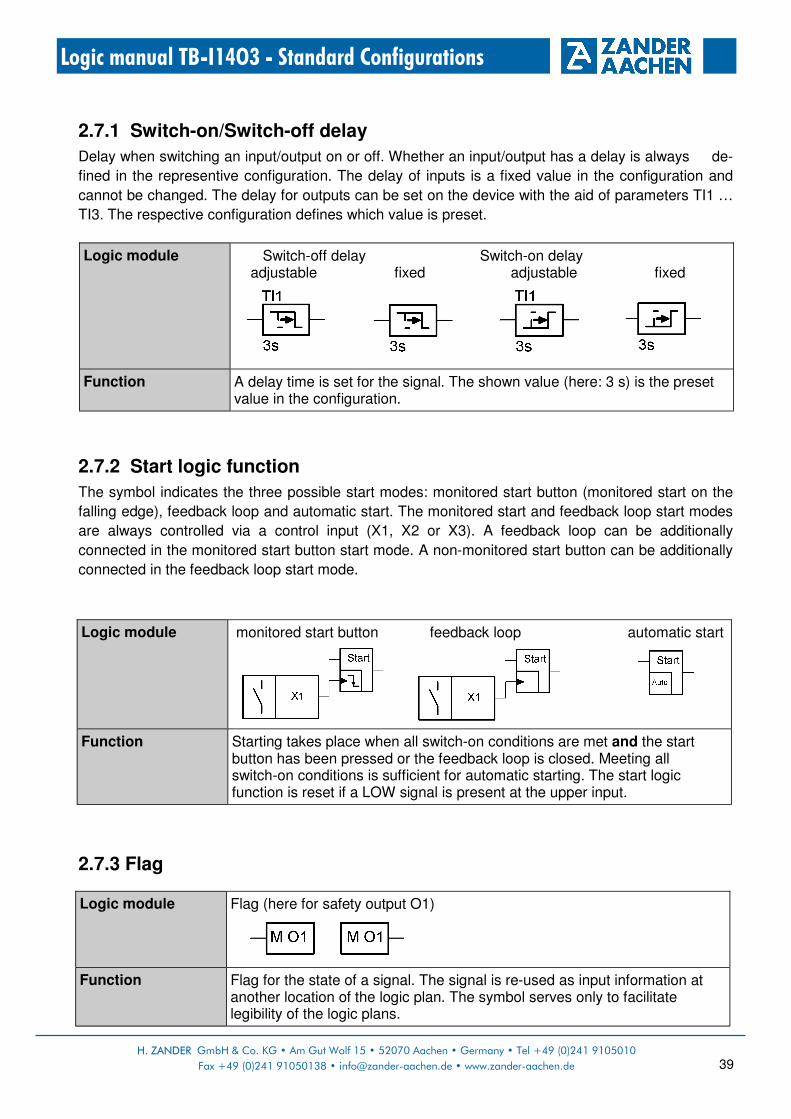
2.7.1 Switch-on/Switch-off delay
Delay when switching an input/output on or off. Whether an input/output has a delay is always de-
fined in the representive configuration. The delay of inputs is a fixed value in the configuration and
cannot be changed. The delay for outputs can be set on the device with the aid of parameters TI1 …
TI3. The respective configuration defines which value is preset.
2.7.2 Start logic function
The symbol indicates the three possible start modes: monitored start button (monitored start on the
falling edge), feedback loop and automatic start. The monitored start and feedback loop start modes
are always controlled via a control input (X1, X2 or X3). A feedback loop can be additionally
connected in the monitored start button start mode. A non-monitored start button can be additionally
connected in the feedback loop start mode.
2.7.3 Flag
Logic module Flag (here for safety output O1)
Function Flag for the state of a signal. The signal is re-used as input information at another location of the logic plan. The symbol serves only to facilitate legibility of the logic plans.
Logic module Switch-off delay Switch-on delay adjustable fixed adjustable fixed
Function A delay time is set for the signal. The shown value (here: 3 s) is the preset value in the configuration.
Logic module monitored start button feedback loop automatic start
Function Starting takes place when all switch-on conditions are met and the start button has been pressed or the feedback loop is closed. Meeting all switch-on conditions is sufficient for automatic starting. The start logic function is reset if a LOW signal is present at the upper input.

H. ZANDER GmbH & Co. KG • Am Gut Wolf 15 • 52070 Aachen • Germany • phone +49 (0)241 9105010
Fax +49 (0)241 91050138 • [email protected] • www.zander-aachen.de 40
Logic manual TB-I14O3 - Standard Configurations
3. Description of the standard configurations
The following chapters describe the standard configurations stored in every device. They
can be loaded into the device memory as active configuration. The logic function of some
configurations cannot be changed. Some configurations permit time parameters to be set on
the device.
Key:
Symbol/text Significance
Safety door, protected by a read head, a safety switch with switching contacts or a safety switch with semiconductor outputs (OSSD).
Emergeny stop circuit
Enabling switch
Operation mode switch
�/� Function intended / function possible
[0s] [3s] […]
without time delay (not adjustable) fixed time delay, here: 3 s (not adjustable) audjustable time delay (0..990 s)
Safety limit switch
Group-Signal

H. ZANDER GmbH & Co. KG • Am Gut Wolf 15 • 52070 Aachen • Germany • Tel +49 (0)241 9105010
Fax +49 (0)241 91050138 • [email protected] • www.zander-aachen.de 41
Logic manual TB-I14O3 - Standard Configurations
3.1 Selection aid for standard configurations
The shown Standard Configurations are merely a first overview. For more details see the
following chapters.
Safe inputs Start behavior / feedback loop
Time Application example
PR00
No function Default setting on delivery, switch device passive
PR01
O1
�
� […]
3 installation section with 2 safety doors each, joint emergency stop.
O2
�
� […]
O3
�
� […]
PR02
O1
�
� […]
3 installation section with 2 safety doors each, joint emergency stop.
O2
�
� […]
O3
�
� […]
PR03
O1
�
[…]
3 installation section with 2 safety doors each, joint emergency stop.
O2
�
[…]
O3
�
[…]
PR04
O1
�
[…]
O2
�
� […]
O3
�
� […]
3 installation sections. Section A: 2 safety doors (alternating operation with one closed safety door in each case), Section B and C: One safety door, joint emergency stop.
Co
nfig
ura
tion
/
ou
tpu
ts
I1-1
/ I1-2
I2-1
/ I2-2
I3-1
/ I3-2
I4-1
/ I4-2
I5-1
/ I5-2
I6-1
/ I6-2
I7-1
/ I7-2
Mo
nito
red
sta
rt
Ma
nu
al sta
rt
Au
tom
atic
sta
rt
Fe
ed
ba
ck loo
p
De
lay
tim
e

H. ZANDER GmbH & Co. KG • Am Gut Wolf 15 • 52070 Aachen • Germany • phone +49 (0)241 9105010
Fax +49 (0)241 91050138 • [email protected] • www.zander-aachen.de 42
Logic manual TB-I14O3 - Standard Configurations
Safe inputs Start behavior /
feedback loop Time Application example
PR05
O1
�
[…] 3 installation sections. Section A: 2 safety doors (alternating operation with one closed safety door in each case), Section B and C: One safety door, joint emergency stop.
O2
�
� […]
O3
�
� […]
PR06
O1
�
[…] 3 installation sections. Section A: 2 safety doors (alternating operation with one closed safety door in each case), Section B and C: One safety door, joint emergency stop.
O2
�
[…]
O3
�
[…]
PR07
O1
�
� […] 5 safety doors, independent emergency circuit, independent enabling circuit.
O2
�
� […]
O3
�
� […]
PR08
O1 �
� […]
5 safety doors, independent emergency circuit, independent enabling circuit.
O2 �
� […]
O3
�
� […]
PR09
O1
�
[…]
O2
�
[…]
O3
�
� […]
5 safety doors, independent emergency circuit, independent enabling circuit.
Co
nfig
ura
tion
/
ou
tpu
ts
I1-1
/ I1-2
I2-1
/ I2-2
I3-1
/ I3-2
I4-1
/ I4-2
I5-1
/ I5-2
I6-1
/ I6-2
I7-1
/ I7-2
Mo
nito
red
sta
rt
Ma
nu
al sta
rt
Au
tom
atic
sta
rt
Fe
ed
ba
ck loo
p
De
lay
tim
e

H. ZANDER GmbH & Co. KG • Am Gut Wolf 15 • 52070 Aachen • Germany • Tel +49 (0)241 9105010
Fax +49 (0)241 91050138 • [email protected] • www.zander-aachen.de 43
Logic manual TB-I14O3 - Standard Configurations
Safe inputs Start behavior /
feedback loop Time Application example
PR10
O1
�
� […] 2 installation sections with three safety doors each, independent emergency stop circuit.
O2
�
� […]
O3
�
� […]
PR11
O1
�
� […] 2 installation sections with three safety doors each, independent emergency stop circuit.
O2
�
� […]
O3
�
� […]
PR12
O1
�
[…] 2 installation sections with three safety doors each, independent emergency stop circuit.
O2
�
[…]
O3
�
[…]
PR13
O1
�
� [0s] 4 safety doors, 1 operation mode switch for mode selectoin, joint emergency stop, 1 safety door for manual mode.
O2
�
� […]
O3
�
� [0s]
PR14
O1
�
� [0s]
O2
�
� […]
O3
�
� […]
5 safety doors, emergency stop, possibility for connection a second TB-I14O3 via group signal.
Co
nfig
ura
tion
/
ou
tpu
ts
I1-1
/ I1-2
I2-1
/ I2-2
I3-1
/ I3-2
I4-1
/ I4-2
I5-1
/ I5-2
I6-1
/ I6-2
I7-1
/ I7-2
Mo
nito
red
sta
rt
Ma
nu
al sta
rt
Au
tom
atic
sta
rt
Fe
ed
ba
ck loo
p
De
lay
tim
e

H. ZANDER GmbH & Co. KG • Am Gut Wolf 15 • 52070 Aachen • Germany • phone +49 (0)241 9105010
Fax +49 (0)241 91050138 • [email protected] • www.zander-aachen.de 44
Logic manual TB-I14O3 - Standard Configurations
3.2 PR00 (factory setting)
In this configuration, no inputs are evaluated and the safety outputs are switched off. The
configuration has no function. However, the state of the inputs is registered and displayed in
the menu DIA.
Safe inputs Start behavior / feedback loop
Time Application example
PR15
O1
�
� [0s] 5 safety doors, emergency stop, possibility for connection a second TB-I14O3 via group signal. O2
�
� […]
O3
�
� […]
PR16
O1
�
[0s] 5 safety doors, emergency stop, possibility for connection a second TB-I14O3 via group signal.
O2
�
[…]
O3
�
[…]
Co
nfig
ura
tion
/
ou
tpu
ts
I1-1
/ I1-2
I2-1
/ I2-2
I3-1
/ I3-2
I4-1
/ I4-2
I5-1
/ I5-2
I6-1
/ I6-2
I7-1
/ I7-2
Mo
nito
red
sta
rt
Ma
nu
al sta
rt
Au
tom
atic
sta
rt
Fe
ed
ba
ck loo
p
De
lay
tim
e

H. ZANDER GmbH & Co. KG • Am Gut Wolf 15 • 52070 Aachen • Germany • Tel +49 (0)241 9105010
Fax +49 (0)241 91050138 • [email protected] • www.zander-aachen.de 45
Logic manual TB-I14O3 - Standard Configurations
3.3 Standard Configuration PR01
3.3.1 Function:
• 3 safety outputs (installation section A, installation section B, installation section C)
• 1 joint emergency stop
• 6 two-channel safe inputs, e.g. for safety doors (two for each section)
• 1 start input for section A
• 1 start input for section B
• 1 start input for section C
3.3.2 Overview:
3.3.3 Function plan:
Quantity Design Description
7 FS-I 2-channel safety inputs with short circuit monitoring and difference time monitoring (same logic state within 3 seconds)
3 Start Inputs for start (monitored) and feedback loop (possible)
3 FS-O Safety outputs, pulsed
6 Aux Auxiliary outputs

H. ZANDER GmbH & Co. KG • Am Gut Wolf 15 • 52070 Aachen • Germany • phone +49 (0)241 9105010
Fax +49 (0)241 91050138 • [email protected] • www.zander-aachen.de 46
Logic manual TB-I14O3 - Standard Configurations
3.3.4 Safety inputs
3.3.5 Standard inputs
Terminal(s) Type Example
I1-1, I1-2 Safety input for 2-channel contacts (NC) with short circuit monitoring
Input for emergency stop chain, 2-channel. Emergency stop actuation generally leads to switch-off of all safety outputs.
I2-1, I2-2 …
I7-1, I7,2
Safety input for 2-channel contacts (NC) with short circuit monitoring
Inputs for safety door circuit, 2-channel. Opening the safety door leads to switch-off of the respective safety output. Attention: If using mechanical safety switches, seperate switches per input must be used (see chapter 2.2.1).
Klemme(n) Typ Anwendungsbeispiel
X1 Monitored start button Start button for installation section A: Pressing and releasing the start button starts O1 if all switch-on conditions are met. Feedback loop: Can be integrated. The feedback loop for safety output O1 must be closed on starting.
X2 Monitored start button Start button for installation section B: Pressing and releasing the start button starts O2 if all switch-on conditions are met. Feedback loop: Can be integrated. The feedback loop for safety output O2 must be closed on starting.
X3 Monitored start button Start button for installation section C: Pressing and releasing the start button starts O3 if all switch-on conditions are met. Feedback loop: Can be integrated. The feedback loop for safety output O3 must be closed on starting.

H. ZANDER GmbH & Co. KG • Am Gut Wolf 15 • 52070 Aachen • Germany • Tel +49 (0)241 9105010
Fax +49 (0)241 91050138 • [email protected] • www.zander-aachen.de 47
Logic manual TB-I14O3 - Standard Configurations
3.3.6 Safety outputs Safety output O1:
Safety assessment of the logic function for O1:
*) The specified PL refers to the maximum achievable value of the respective logic function in
subsystem TB-I14O3.
Terminal(s) Type Example
O1 Safety output, pulsed, switch-off delay possible.
Output switches off as soon as the switch-on condition no longer exists. The time-delay can be adjusted via parameter TI1 in the CONF menu (factory setting is 0 second). Switch-on condition: • Emergency-stop not pressed • All safety doors section A are closed (I2-1,
I2-2 and I3-1, I3-2) • Press and release start button
Input Example TM
[Year]
I1-1, I1-2 Emergency stop chain 20
I2-1, I2-2 Safety door 1, installation section A 20
I3-1, I3-2 Safety door 2, installation section A 20
X1 Start button for installation section A 20
PFH [1/h]
7,19E-09
7,19E-09
7,19E-09
1,15E-06
Cat.
4
4
4
1
PL*
e
e
e
c

H. ZANDER GmbH & Co. KG • Am Gut Wolf 15 • 52070 Aachen • Germany • phone +49 (0)241 9105010
Fax +49 (0)241 91050138 • [email protected] • www.zander-aachen.de 48
Logic manual TB-I14O3 - Standard Configurations
Safety output O2:
Safety assessment of the logic function for O2:
*) The specified PL refers to the maximum achievable value of the respective logic function in subsystem TB-I14O3.
Terminal(s) Typs Example
O2 Safety output, pulsed, switch-off delay possible.
Output switches off as soon as the switch-on condition no longer exists. The time-delay can be adjusted via parameter TI2 in the CONF menu (factory setting is 0 second). Switch-on condition: • Emergency-stop not pressed • All safety doors section B are closed
(I4-1, I4-2 and I5-1, I5-2) • Press and release start button
Input Example PL*
I1-1, I1-2 Emergency stop chain e
I4-1, I4-2 Safety door 1, installation section A e
I5-1, I5-2 Safety door 2, installation section A e
X2 Start button for installation section A c
Cat.
4
4
4
1
PFH [1/h]
7,19E-09
7,19E-09
7,19E-09
1,15E-06
TM
[Year]
20
20
20
20

H. ZANDER GmbH & Co. KG • Am Gut Wolf 15 • 52070 Aachen • Germany • Tel +49 (0)241 9105010
Fax +49 (0)241 91050138 • [email protected] • www.zander-aachen.de 49
Logic manual TB-I14O3 - Standard Configurations
Safety output O3:
Safety assessment of the logic function for O3:
*) The specified PL refers to the maximum achievable value of the respective logic function in
subsystem TB-I14O3.
Terminal(s) Typs Example
O2 Safety output, pulsed, switch-off delay possible.
Output switches off as soon as the switch-on condition no longer exists. The time-delay can be adjusted via parameter TI3 in the CONF menu (factory setting is 0 second). Switch-on condition: • Emergency-stop not pressed • All safety doors section C are closed (I6-1, I6-2 und I7-1, I7-2) • Press and release start button
Input Example PL*
I1-1, I1-2 Emergency stop chain e
I6-1, I6-2 Safety door 1, installation section A e
I7-1, I7-2 Safety door 2, installation section A e
X3 Start button for installation section A c
Cat.
4
4
4
1
PFH [1/h]
7,19E-09
7,19E-09
7,19E-09
1,15E-06
TM
[Year]
20
20
20
20

H. ZANDER GmbH & Co. KG • Am Gut Wolf 15 • 52070 Aachen • Germany • phone +49 (0)241 9105010
Fax +49 (0)241 91050138 • [email protected] • www.zander-aachen.de 50
Logic manual TB-I14O3 - Standard Configurations
3.3.7 Auxiliary outputs Auxiliary outputs C0..C2:
Auxiliary outputs C3..C5:
Terminal(s) Type Example
C0 Auxiliary output C0 is active, if both safety doors of installation section A are closed (Safety door 1 at I2-1, I2-2 and safety door 2 at I3-1, I3-2).
C1 Auxiliary output C1 is active, if both safety doors of installation section B are closed (Safety door 3 at I4-1, I4-2 and safety door 4 at I5-1, I5-2).
C2 Auxiliary output C2 is active, if both safety doors of installation section C are closed (Safety door 5 at I6-1, I6-2 and safety door 6 at I7-1, I7-2).
Terminal(s) Type Example
C3 Auxiliary output Auxiliary output for O1. Switch-on and switch-off conditions like O1, but non-delayed.
C4 Auxiliary output Auxiliary output for O2. Switch-on and switch-off conditions like O2, but non-delayed.
C5 Auxiliary output Auxiliary output for O3. Switch-on and switch-off conditions like O3, but non-delayed.
H. ZANDER GmbH & Co. KG • Am Gut Wolf 15 • 52070 Aachen • Germany • Tel +49 (0)241 9105010
Fax +49 (0)241 91050138 • [email protected] • www.zander-aachen.de 51
Logic manual TB-I14O3 - Standard Configurations
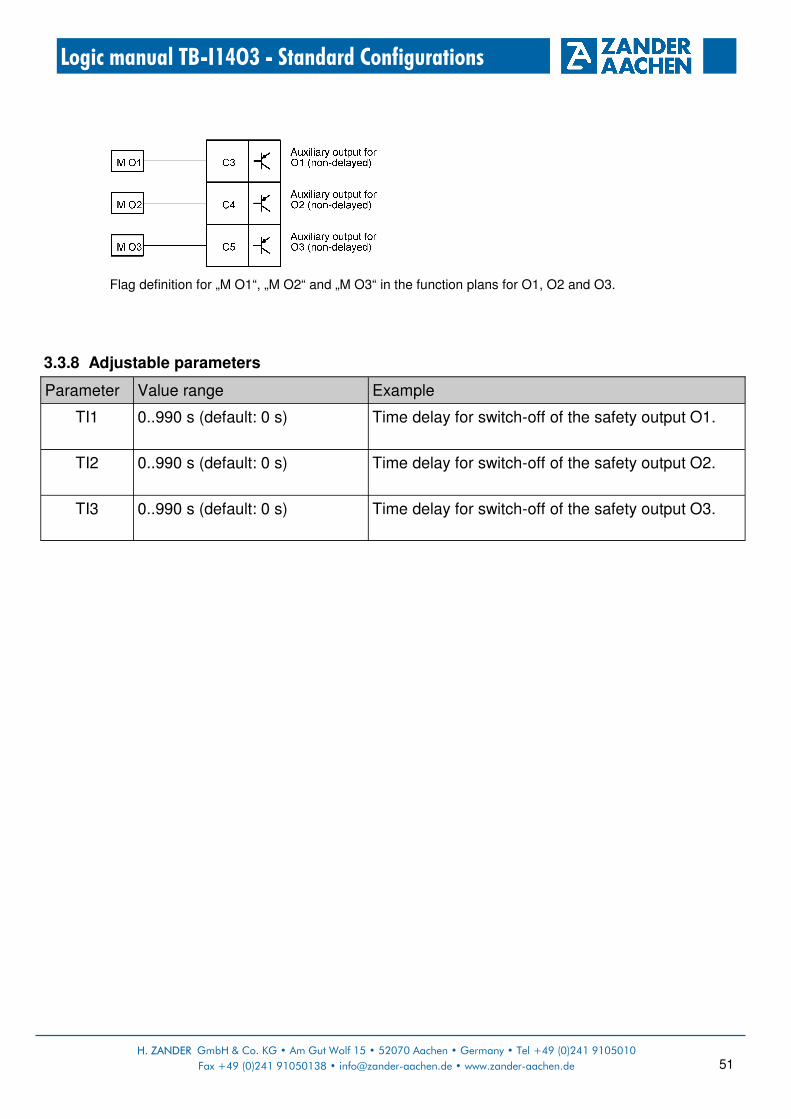
Flag definition for „M O1“, „M O2“ and „M O3“ in the function plans for O1, O2 and O3.
3.3.8 Adjustable parameters
Parameter Value range Example
TI1 0..990 s (default: 0 s) Time delay for switch-off of the safety output O1.
TI2 0..990 s (default: 0 s) Time delay for switch-off of the safety output O2.
TI3 0..990 s (default: 0 s) Time delay for switch-off of the safety output O3.

H. ZANDER GmbH & Co. KG • Am Gut Wolf 15 • 52070 Aachen • Germany • phone +49 (0)241 9105010
Fax +49 (0)241 91050138 • [email protected] • www.zander-aachen.de 52
Logic manual TB-I14O3 - Standard Configurations
3.4 Standard Configuration PR02
3.4.1 Function:
• 3 safety outputs (installation section A, installation section B, installation section C)
• 1 joint emergency stop
• 6 two-channel safe inputs, e.g. for safety doors (two for each section)
• 1 feedback loop for installation section A
• 1 feedback loop for installation section B
• 1 feedback loop for installation section C
3.4.2 Overview:
3.4.3 Function plan:
Quantity Design Description
7 FS-I 2-channel safety inputs with short circuit monitoring and difference time monitoring (same logic state within 2 seconds)
3 FL Feedback loop. With or without start button (non-monitored)
3 FS-O Safety outputs, pulsed
6 Aux Auxiliary outputs
H. ZANDER GmbH & Co. KG • Am Gut Wolf 15 • 52070 Aachen • Germany • Tel +49 (0)241 9105010
Fax +49 (0)241 91050138 • [email protected] • www.zander-aachen.de 53
Logic manual TB-I14O3 - Standard Configurations
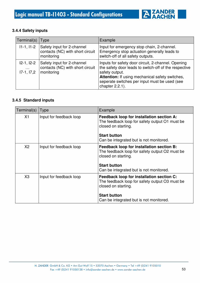
3.4.4 Safety inputs
3.4.5 Standard inputs
Terminal(s) Type Example
I1-1, I1-2 Safety input for 2-channel contacts (NC) with short circuit monitoring
Input for emergency stop chain, 2-channel. Emergency stop actuation generally leads to switch-off of all safety outputs.
I2-1, I2-2 …
I7-1, I7,2
Safety input for 2-channel contacts (NC) with short circuit monitoring
Inputs for safety door circuit, 2-channel. Opening the safety door leads to switch-off of the respective safety output. Attention: If using mechanical safety switches, seperate switches per input must be used (see chapter 2.2.1).
Terminal(s) Type Example
X1 Input for feedback loop Feedback loop for installation section A: The feedback loop for safety output O1 must be closed on starting. Start button Can be integrated but is not monitored.
X2 Input for feedback loop Feedback loop for installation section B: The feedback loop for safety output O2 must be closed on starting. Start button Can be integrated but is not monitored.
X3 Input for feedback loop Feedback loop for installation section C: The feedback loop for safety output O3 must be closed on starting. Start button Can be integrated but is not monitored.

H. ZANDER GmbH & Co. KG • Am Gut Wolf 15 • 52070 Aachen • Germany • phone +49 (0)241 9105010
Fax +49 (0)241 91050138 • [email protected] • www.zander-aachen.de 54
Logic manual TB-I14O3 - Standard Configurations
3.4.6 Safety outputs Safety output O1:
Safety assessment of the logic function for O1:
*) The specified PL refers to the maximum achievable value of the respective logic function in
subsystem TB-I14O3.
Terminal(s) Type Example
O1 Safety output, pulsed, switch-off delay possible
Output switches off as soon as the switch-on condition no longer exists. The time-delay can be adjusted via parameter TI1 in the CONF menu (factory setting is 0 second). Switch-on condition: • Emergency-stop not pressed • All safety doors section A are closed
(I2-1, I2-2 and I3-1, I3-2) • Feedback loop X1 is closed
Input Example PL*
I1-1, I1-2 Emergency stop chain e
I2-1, I2-2 Safety door 1, installation section A e
I3-1, I3-2 Safety door 2, installation section A e
X1 Start button for installation section A c
Cat.
4
4
4
1
PFH [1/h]
7,19E-09
7,19E-09
7,19E-09
1,15E-06
TM
[Year]
20
20
20
20

H. ZANDER GmbH & Co. KG • Am Gut Wolf 15 • 52070 Aachen • Germany • Tel +49 (0)241 9105010
Fax +49 (0)241 91050138 • [email protected] • www.zander-aachen.de 55
Logic manual TB-I14O3 - Standard Configurations
Safety output O2:
Safety assessment of the logic function for O2:
*) The specified PL refers to the maximum achievable value of the respective logic function in subsystem TB-I14O3.
Terminal(s) Typs Example
O2 Safety output, pulsed, switch-off delay possible.
Output switches off as soon as the switch-on condition no longer exists. The time-delay can be adjusted via parameter TI2 in the CONF menu (factory setting is 0 second). Switch-on condition: • Emergency-stop not pressed • All safety doors section B are closed
(I4-1, I4-2 and I5-1, I5-2) • Feedback loop X2 is closed
Input Example PL*
I1-1, I1-2 Emergency stop chain e
I4-1, I4-2 Safety door 1, installation section A e
I5-1, I5-2 Safety door 2, installation section A e
X2 Start button for installation section A c
Cat.
4
4
4
1
PFH [1/h]
7,19E-09
7,19E-09
7,19E-09
1,15E-06
TM
[Year]
20
20
20
20

H. ZANDER GmbH & Co. KG • Am Gut Wolf 15 • 52070 Aachen • Germany • phone +49 (0)241 9105010
Fax +49 (0)241 91050138 • [email protected] • www.zander-aachen.de 56
Logic manual TB-I14O3 - Standard Configurations
Safety output O3:
Safety assessment of the logic function for O3:
*) The specified PL refers to the maximum achievable value of the respective logic function in
subsystem TB-I14O3.
Terminal(s) Typs Example
O3 Safety output, pulsed, switch-off delay possible.
Output switches off as soon as the switch-on condition no longer exists. The time-delay can be adjusted via parameter TI3 in the CONF menu (factory setting is 0 second). Switch-on condition: • Emergency-stop not pressed • All safety doors section C are closed
(I6-1, I6-2 und I7-1, I7-2) • Feedback loop X3 is closed
Input Example PL*
I1-1, I1-2 Emergency stop chain e
I6-1, I6-2 Safety door 1, installation section A e
I7-1, I7-2 Safety door 2, installation section A e
X3 Start button for installation section A c
Cat.
4
4
4
1
PFH [1/h]
7,19E-09
7,19E-09
7,19E-09
1,15E-06
TM
[Year]
20
20
20
20

H. ZANDER GmbH & Co. KG • Am Gut Wolf 15 • 52070 Aachen • Germany • Tel +49 (0)241 9105010
Fax +49 (0)241 91050138 • [email protected] • www.zander-aachen.de 57
Logic manual TB-I14O3 - Standard Configurations
3.4.7 Auxiliary outputs Auxiliary outputs C0..C2:
Auxiliary outputs C3..C5:
Terminal(s) Type Example
C0 Auxiliary output C0 is active, if both safety doors of installation section A are closed (Safety door 1 at I2-1, I2-2 and safety door 2 at I3-1, I3-2).
C1 Auxiliary output C1 is active, if both safety doors of installation section B are closed (Safety door 3 at I4-1, I4-2 and safety door 4 at I5-1, I5-2).
C2 Auxiliary output C2 is active, if both safety doors of installation section C are closed (Safety door 5 at I6-1, I6-2 and safety door 6 at I7-1, I7-2).
Terminal(s) Type Example
C3 Auxiliary output Auxiliary output for O1. Switch-on and switch-off conditions like O1, but non-delayed.
C4 Auxiliary output Auxiliary output for O2. Switch-on and switch-off conditions like O2, but non-delayed.
C5 Auxiliary output Auxiliary output for O3. Switch-on and switch-off conditions like O3, but non-delayed.

H. ZANDER GmbH & Co. KG • Am Gut Wolf 15 • 52070 Aachen • Germany • phone +49 (0)241 9105010
Fax +49 (0)241 91050138 • [email protected] • www.zander-aachen.de 58
Logic manual TB-I14O3 - Standard Configurations
Flag definition for „M O1“, „M O2“ and „M O3“ in the function plans for O1, O2 and O3.
3.4.8 Adjustable parameters
Parameter Value range Example
TI1 0..990 s (default: 0 s) Time delay for switch-off of the safety output O1.
TI2 0..990 s (default: 0 s) Time delay for switch-off of the safety output O2.
TI3 0..990 s (default: 0 s) Time delay for switch-off of the safety output O3.

H. ZANDER GmbH & Co. KG • Am Gut Wolf 15 • 52070 Aachen • Germany • Tel +49 (0)241 9105010
Fax +49 (0)241 91050138 • [email protected] • www.zander-aachen.de 59
Logic manual TB-I14O3 - Standard Configurations
3.5 Standard Configuration PR03
3.5.1 Function:
• 3 safety outputs (installation section A, installation section B, installation section C)
• 1 joint emergency stop
• 6 two-channel safe inputs, e.g. for safety doors (two for each section)
• Automatic start for all safety outputs
3.5.2 Overview:
3.5.3 Function plan:
Quantity Design Description
7 FS-I 2-channel safety inputs with short circuit monitoring and difference time monitoring (same logic state within 3 seconds)
3 FS-O Safety outputs, pulsed
6 Aux Auxiliary outputs

H. ZANDER GmbH & Co. KG • Am Gut Wolf 15 • 52070 Aachen • Germany • phone +49 (0)241 9105010
Fax +49 (0)241 91050138 • [email protected] • www.zander-aachen.de 60
Logic manual TB-I14O3 - Standard Configurations
3.5.4 Safety inputs
Terminal(s) Type Example
I1-1, I1-2 Safety input for 2-channel contacts (NC) with short circuit monitoring
Input for emergency stop chain, 2-channel. Emergency stop actuation generally leads to switch-off of all safety outputs.
I2-1, I2-2 …
I7-1, I7,2
Safety input for 2-channel contacts (NC) with short circuit monitoring
Inputs for safety door circuit, 2-channel. Opening the safety door leads to switch-off of the respective safety output. Attention: If using mechanical safety switches, seperate switches per input must be used (see chapter 2.2.1).
3.5.5 Safety outputs Safety output O1:
Safety assessment of the logic function for O1:
*) The specified PL refers to the maximum achievable value of the respective logic function in subsystem TB-I14O3.
Terminal(s) Type Example
O1 Safety output, pulsed, switch-off delay possible
Output switches off as soon as the switch-on condition no longer exists. The time-delay can be adjusted via parameter TI1 in the CONF menu (factory setting is 0 second). Switch-on condition: • Emergency-stop not pressed • All safety doors section A are closed
(I2-1, I2-2 and I3-1, I3-2) • Automatic start
Input Example PL*
I1-1, I1-2 Emergency stop chain e
I2-1, I2-2 Safety door 1, installation section A e
I3-1, I3-2 Safety door 2, installation section A e
- Danger due to the safe output switching back on after a stop. No manual reset according to EN ISO 13849.
-
Cat.
4
4
4
-
PFH [1/h]
7,19E-09
7,19E-09
7,19E-09
-
TM
[Year]
20
20
20
-

H. ZANDER GmbH & Co. KG • Am Gut Wolf 15 • 52070 Aachen • Germany • Tel +49 (0)241 9105010
Fax +49 (0)241 91050138 • [email protected] • www.zander-aachen.de 61
Logic manual TB-I14O3 - Standard Configurations
Safety output O2:
Safety assessment of the logic function for O2:
*) The specified PL refers to the maximum achievable value of the respective logic function in subsystem TB-I14O3.
Terminal(s) Typs Example
O2 Safety output, pulsed, switch-off delay possible.
Output switches off as soon as the switch-on condition no longer exists. The time-delay can be adjusted via parameter TI2 in the CONF menu (factory setting is 0 second). Switch-on condition: • Emergency-stop not pressed • All safety doors section B are closed
(I4-1, I4-2 and I5-1, I5-2) • Automatic start
Input Example PL*
I1-1, I1-2 Emergency stop chain e
I4-1, I4-2 Safety door 1, installation section A e
I5-1, I5-2 Safety door 2, installation section A e
- Danger due to the safe output switching back on after a stop. No manual reset according to EN ISO 13849.
-
Cat.
4
4
4
-
PFH [1/h]
7,19E-09
7,19E-09
7,19E-09
-
TM
[Year]
20
20
20
-

H. ZANDER GmbH & Co. KG • Am Gut Wolf 15 • 52070 Aachen • Germany • phone +49 (0)241 9105010
Fax +49 (0)241 91050138 • [email protected] • www.zander-aachen.de 62
Logic manual TB-I14O3 - Standard Configurations
Safety output O3:
Safety assessment of the logic function for O3:
*) The specified PL refers to the maximum achievable value of the respective logic function in subsystem TB-I14O3.
Terminal(s) Typs Example
O2 Safety output, pulsed, switch-off delay possible.
Output switches off as soon as the switch-on condition no longer exists. The time-delay can be adjusted via parameter TI3 in the CONF menu (factory setting is 0 second). Switch-on condition: • Emergency-stop not pressed • All safety doors section C are closed
(I6-1, I6-2 und I7-1, I7-2) • Automatic start
Input Example PL*
I1-1, I1-2 Emergency stop chain e
I6-1, I6-2 Safety door 1, installation section A e
I7-1, I7-2 Safety door 2, installation section A e
- Danger due to the safe output switching back on after a stop. No manual reset according to EN ISO 13849.
-
Cat.
4
4
4
-
PFH [1/h]
7,19E-09
7,19E-09
7,19E-09
-
TM
[Year]
20
20
20
-

H. ZANDER GmbH & Co. KG • Am Gut Wolf 15 • 52070 Aachen • Germany • Tel +49 (0)241 9105010
Fax +49 (0)241 91050138 • [email protected] • www.zander-aachen.de 63
Logic manual TB-I14O3 - Standard Configurations
3.5.6 Auxiliary outputs Auxiliary outputs C0..C2:
Auxiliary outputs C3..C5:
Terminal(s) Type Example
C0 Auxiliary output C0 is active, if both safety doors of installation section A are closed (Safety door 1 at I2-1, I2-2 and safety door 2 at I3-1, I3-2).
C1 Auxiliary output C1 is active, if both safety doors of installation section B are closed (Safety door 3 at I4-1, I4-2 and safety door 4 at I5-1, I5-2).
C2 Auxiliary output C2 is active, if both safety doors of installation section C are closed (Safety door 5 at I6-1, I6-2 and safety door 6 at I7-1, I7-2).
Terminal(s) Type Example
C3 Auxiliary output Auxiliary output for O1. Switch-on and switch-off conditions like O1, but non-delayed.
C4 Auxiliary output Auxiliary output for O2. Switch-on and switch-off conditions like O2, but non-delayed.
C5 Auxiliary output Auxiliary output for O3. Switch-on and switch-off conditions like O3, but non-delayed.

H. ZANDER GmbH & Co. KG • Am Gut Wolf 15 • 52070 Aachen • Germany • phone +49 (0)241 9105010
Fax +49 (0)241 91050138 • [email protected] • www.zander-aachen.de 64
Logic manual TB-I14O3 - Standard Configurations
Flag definition for „M O1“, „M O2“ and „M O3“ in the function plans for O1, O2 and O3.
3.5.7 Adjustable parameters
Parameter Value range Example
TI1 0..990 s (default: 0 s) Time delay for switch-off of the safety output O1.
TI2 0..990 s (default: 0 s) Time delay for switch-off of the safety output O2.
TI3 0..990 s (default: 0 s) Time delay for switch-off of the safety output O3.

H. ZANDER GmbH & Co. KG • Am Gut Wolf 15 • 52070 Aachen • Germany • Tel +49 (0)241 9105010
Fax +49 (0)241 91050138 • [email protected] • www.zander-aachen.de 65
Logic manual TB-I14O3 - Standard Configurations
3.6 Standard Configuration PR04
3.6.1 Function:
• 3 safety outputs (installation section A, installation section B, installation section C)
• 1 joint emergency stop
• 6 two-channel safe inputs, 4 safety doors (two for installation section A, 1 for installation section B and C), 2 safety switches (e.g. ZCode) as position switch for alternating operation at installation section A
• 1 start, installation section B
• 1 start, installation section C
3.6.2 Overview:
3.6.3 Function plan:
Quantity Type Description
7 FS-I 2-channel safety inputs with short circuit monitoring and difference time monitoring (same logic state within 3 seconds)
2 Start Inputs for start button (monitored) and feedback loop (possible)
3 FS-O Safety outputs, pulsed
6 Aux Auxiliary outputs

H. ZANDER GmbH & Co. KG • Am Gut Wolf 15 • 52070 Aachen • Germany • phone +49 (0)241 9105010
Fax +49 (0)241 91050138 • [email protected] • www.zander-aachen.de 66
Logic manual TB-I14O3 - Standard Configurations
3.6.4 Safety inputs
3.6.5 Standard inputs
Terminal(s) Type Example
I1-1, I1-2 Safety input for 2-channel contacts (NC) with short circuit monitoring
Input for emergency stop chain, 2-channel. Emergency stop actuation generally leads to switch-off of all safety outputs.
I2-1, I2-2 I4-1, I4-2 I6-1, I6-2 I7-1, I7,2
Safety input for 2-channel contacts (NC) with short circuit monitoring
Inputs for safety door circuit, 2-channel. Opening the safety door leads to switch-off of the respective safety output. Attention: If using mechanical safety switches, seperate switches per input must be used (see chapter 2.2.1).
I3-1, I3-2 I5-1, I5-2
Safety input for non-contacts safety switches (e.g. ZCode), 2-channel with short circuit mo-nitoring
Inputs for position switch, 2-channel, e.g. for alternating operation to register in which section the danger movement takes place.
Terminal(s) Type Example
X2 Monitored start button Start button for installation section B: Pressing and releasing the start button starts O2 if all switch-on conditions are met. Feedback loop: Can be integrated. The feedback loop for safety output O2 must be closed on starting.
X3 Monitored start button Start button for installation section C: Pressing and releasing the start button starts O3 if all switch-on conditions are met. Feedback loop: Can be integrated. The feedback loop for safety output O3 must be closed on starting.

H. ZANDER GmbH & Co. KG • Am Gut Wolf 15 • 52070 Aachen • Germany • Tel +49 (0)241 9105010
Fax +49 (0)241 91050138 • [email protected] • www.zander-aachen.de 67
Logic manual TB-I14O3 - Standard Configurations
3.6.6 Safety outputs Safety output O1:
Safety assessment of the logic function for O1:
*) The specified PL refers to the maximum achievable value of the respective logic function in subsystem TB-I14O3.
Terminal(s) Type Example
O1 Safety output, pulsed, switch-off delay possible.
Output switches off as soon as the switch-on condition no longer exists. The time-delay can be adjusted via parameter TI1 in the CONF menu. Switch-on condition: • Emergency-stop not pressed • Safety door 1 AND safety door 2 are closed OR
safety door 1 AND positon switch 1 are closed OR safety door 2 AND position switch 2 are closed (safety doors and position swtiches belongs to installation section A)
(I2-1, I2-2 AND I4-1, I4-2 OR I2-1, I2-2 AND I3-1, I3-2 OR I4-1, I4-2 AND I5-1, I5-2).
Input Example PL*
I1-1, I1-2 Emergency stop chain e
I2-1, I2-2 Safety door 1, installation section A e
I4-1, I4-2 Safety door 2, installation section A e
- Danger due to the safe output switching back on after a stop. No manual reset according to EN ISO 13849
-
I3-1, I3-2 Position switch 1 e
I5-1, I5-2 Position switch 2 e
Cat.
4
4
4
4
4
-
PFH [1/h]
7,19E-09
7,19E-09
7,19E-09
7,19E-09
7,19E-09
-
TM
[Year]
20
20
20
20
20
-

H. ZANDER GmbH & Co. KG • Am Gut Wolf 15 • 52070 Aachen • Germany • phone +49 (0)241 9105010
Fax +49 (0)241 91050138 • [email protected] • www.zander-aachen.de 68
Logic manual TB-I14O3 - Standard Configurations
Safety output O2:
Safety assessment of the logic function for O2:
*) The specified PL refers to the maximum achievable value of the respective logic function in subsystem TB-I14O3.
Terminal(s) Type Example
O2 Safety output, pulsed, switch-off delay possible.
Output switches off as soon as the switch-on condition no longer exists. The time-delay can be adjusted via parameter TI2 in the CONF menu (factory setting is 0 second). Switch-on condition: • Emergency-stop not pressed • Safety door of installation section B is closed
(I6-1, I6-2). • Press and release start button at X2
Input Example PL*
I1-1, I1-2 Emergency stop chain e
I6-1, I6-2 Safety door 3, installation section B e
X2 Start button, installation section B c
Cat.
4
4
1
PFH [1/h]
7,19E-09
7,19E-09
1,15E-06
TM
[Year]
20
20
20

H. ZANDER GmbH & Co. KG • Am Gut Wolf 15 • 52070 Aachen • Germany • Tel +49 (0)241 9105010
Fax +49 (0)241 91050138 • [email protected] • www.zander-aachen.de 69
Logic manual TB-I14O3 - Standard Configurations
Safety output O3:
Safety assessment of the logic function for O3:
*) The specified PL refers to the maximum achievable value of the respective logic function in subsystem TB-I14O3.
Terminal(s) Type Example
O3 Safety output, pulsed, switch-off delay possible.
Output switches off as soon as the switch-on condition no longer exists. The time-delay can be adjusted via parameter TI3 in the CONF menu (factory setting is 0 second). Switch-on condition: • Emergency-stop not pressed • Safety door of installation section C is closed
(I7-1, I7-2) • Press and release start button at X2
Input Example PL*
I1-1, I1-2 Emergency stop chain e
I7-1, I7-2 Safety door 4, installation section C e
X3 Start button, installation section C c
Cat.
4
4
1
PFH [1/h]
7,19E-09
7,19E-09
1,15E-06
TM
[Year]
20
20
20
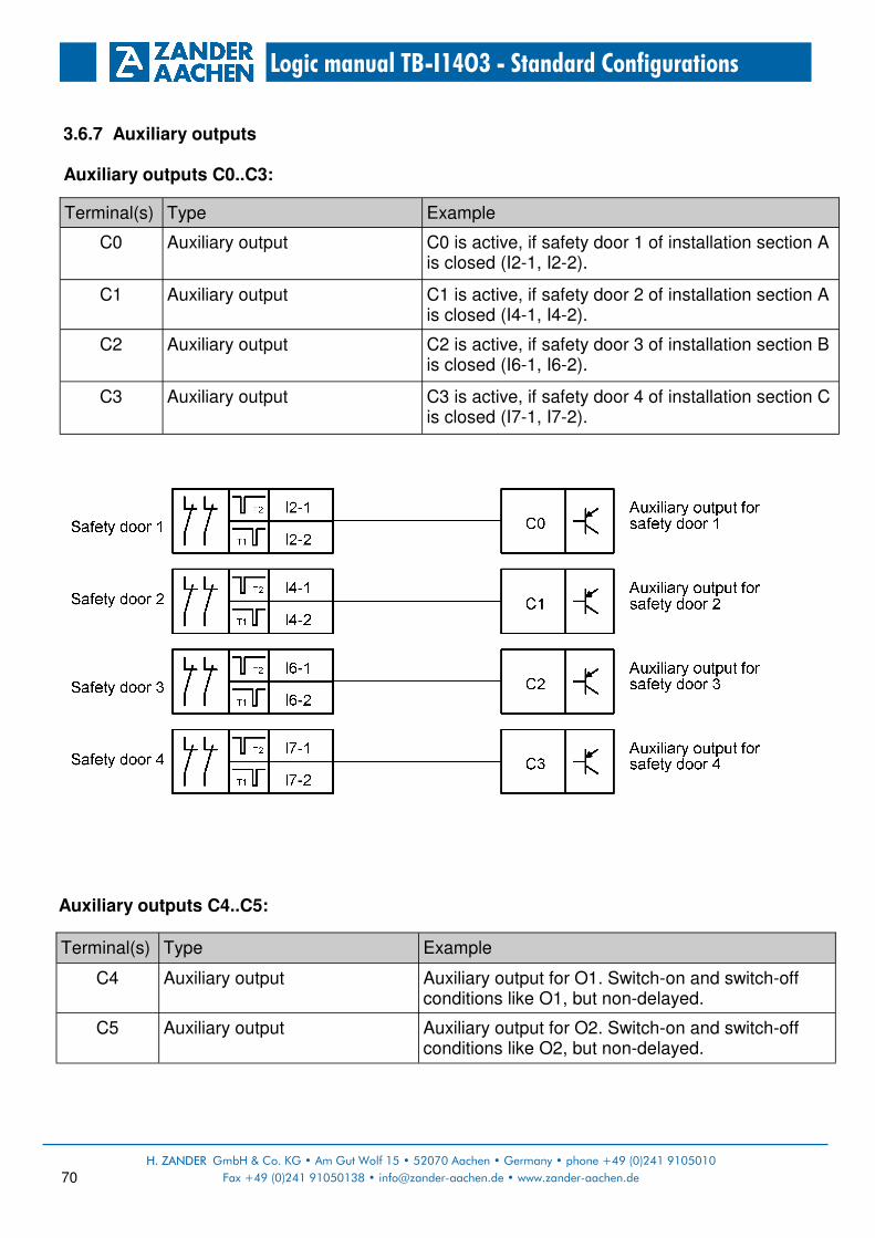
H. ZANDER GmbH & Co. KG • Am Gut Wolf 15 • 52070 Aachen • Germany • phone +49 (0)241 9105010
Fax +49 (0)241 91050138 • [email protected] • www.zander-aachen.de 70
Logic manual TB-I14O3 - Standard Configurations
3.6.7 Auxiliary outputs Auxiliary outputs C0..C3:
Auxiliary outputs C4..C5:
Terminal(s) Type Example
C0 Auxiliary output C0 is active, if safety door 1 of installation section A is closed (I2-1, I2-2).
C1 Auxiliary output C1 is active, if safety door 2 of installation section A is closed (I4-1, I4-2).
C2 Auxiliary output C2 is active, if safety door 3 of installation section B is closed (I6-1, I6-2).
C3 Auxiliary output C3 is active, if safety door 4 of installation section C is closed (I7-1, I7-2).
Terminal(s) Type Example
C4 Auxiliary output Auxiliary output for O1. Switch-on and switch-off conditions like O1, but non-delayed.
C5 Auxiliary output Auxiliary output for O2. Switch-on and switch-off conditions like O2, but non-delayed.

H. ZANDER GmbH & Co. KG • Am Gut Wolf 15 • 52070 Aachen • Germany • Tel +49 (0)241 9105010
Fax +49 (0)241 91050138 • [email protected] • www.zander-aachen.de 71
Logic manual TB-I14O3 - Standard Configurations
Flag definition for „M O1“ and „M O2“ in the function plans for O1 and O2.
3.6.8 Adjustable parameter
Parameter Value range Example
TI1 0..990 s (default: 0 s) Time delay for switch-off of the safety output O1.
TI2 0..990 s (default: 0 s) Time delay for switch-off of the safety output O2.
TI3 0..990 s (default: 0 s) Time delay for switch-off of the safety output O3.
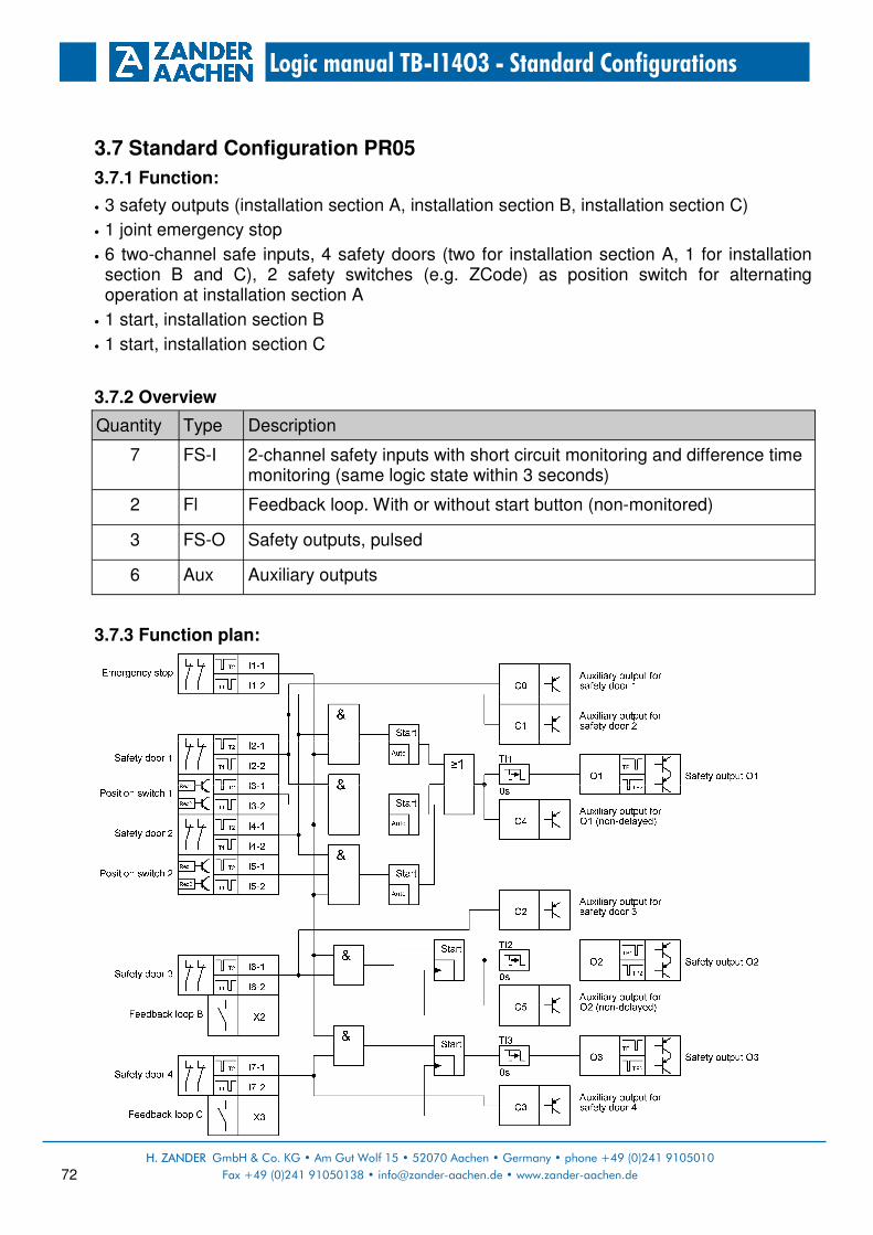
H. ZANDER GmbH & Co. KG • Am Gut Wolf 15 • 52070 Aachen • Germany • phone +49 (0)241 9105010
Fax +49 (0)241 91050138 • [email protected] • www.zander-aachen.de 72
Logic manual TB-I14O3 - Standard Configurations
3.7 Standard Configuration PR05
3.7.1 Function:
• 3 safety outputs (installation section A, installation section B, installation section C)
• 1 joint emergency stop
• 6 two-channel safe inputs, 4 safety doors (two for installation section A, 1 for installation section B and C), 2 safety switches (e.g. ZCode) as position switch for alternating operation at installation section A
• 1 start, installation section B
• 1 start, installation section C
3.7.2 Overview
3.7.3 Function plan:
Quantity Type Description
7 FS-I 2-channel safety inputs with short circuit monitoring and difference time monitoring (same logic state within 3 seconds)
2 Fl Feedback loop. With or without start button (non-monitored)
3 FS-O Safety outputs, pulsed
6 Aux Auxiliary outputs

H. ZANDER GmbH & Co. KG • Am Gut Wolf 15 • 52070 Aachen • Germany • Tel +49 (0)241 9105010
Fax +49 (0)241 91050138 • [email protected] • www.zander-aachen.de 73
Logic manual TB-I14O3 - Standard Configurations
3.7.4 Safety inputs
3.7.5 Standard inputs
Terminal(s) Type Example
I1-1, I1-2 Safety input for 2-channel contacts (NC) with short circuit monitoring
Input for emergency stop chain, 2-channel. Emergency stop actuation generally leads to switch-off of all safety outputs.
I2-1, I2-2 I4-1, I4-2 I6-1, I6-2 I7-1, I7-2
Safety input for 2-channel contacts (NC) with short circuit monitoring
Inputs for safety door circuit, 2-channel. Opening the safety door leads to switch-off of the respective safety output. Attention: If using mechanical safety switches, seperate switches per input must be used (see chapter 2.2.1).
I3-1, I3-2 I5-1, I5-2
Safety input for non-contact safety switches (e.g. ZCode), 2-channel with short circuit monitoring
Inputs for position switch, 2-channel, e.g. for alternating operation to register in which section the danger movement takes place.
Terminal(s) Type Example
X2 Feedback loop Feedback loop for installation section B: The feedback loop for safety output O2 must be closed on starting. Start button can be integrated but is not monitored.
X3 Feedback loop Feedback loop for installation section C: The feedback loop for safety output O3 must be closed on starting. Start button can be integrated but is not monitored.
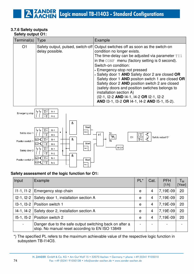
H. ZANDER GmbH & Co. KG • Am Gut Wolf 15 • 52070 Aachen • Germany • phone +49 (0)241 9105010
Fax +49 (0)241 91050138 • [email protected] • www.zander-aachen.de 74
Logic manual TB-I14O3 - Standard Configurations
3.7.6 Safety outputs Safety output O1:
Safety assessment of the logic function for O1:
*) The specified PL refers to the maximum achievable value of the respective logic function in subsystem TB-I14O3.
Terminal(s) Type Example
O1 Safety output, pulsed, switch-off delay possible.
Output switches off as soon as the switch-on condition no longer exists. The time-delay can be adjusted via parameter TI1 in the CONF menu (factory setting is 0 second). Switch-on condition: • Emergency-stop not pressed • Safety door 1 AND Safety door 2 are closed OR
Safety door 1 AND positon switch 1 are closed OR Safety door 2 AND position switch 2 are closed (safety doors and position swtiches belongs to installation section A)
(I2-1, I2-2 AND I4-1, I4-2 OR I2-1, I2-2 AND I3-1, I3-2 OR I4-1, I4-2 AND I5-1, I5-2).
Input Example PL*
I1-1, I1-2 Emergency stop chain e
I2-1, I2-2 Safety door 1, installation section A e
I4-1, I4-2 Safety door 2, installation section A e
- Danger due to the safe output switching back on after a stop. No manual reset according to EN ISO 13849
-
I3-1, I3-2 Position switch 1 e
I5-1, I5-2 Position switch 2 e
Cat.
4
4
4
4
4
-
PFH [1/h]
7,19E-09
7,19E-09
7,19E-09
7,19E-09
7,19E-09
-
TM
[Year]
20
20
20
20
20
-

H. ZANDER GmbH & Co. KG • Am Gut Wolf 15 • 52070 Aachen • Germany • Tel +49 (0)241 9105010
Fax +49 (0)241 91050138 • [email protected] • www.zander-aachen.de 75
Logic manual TB-I14O3 - Standard Configurations
Safety output O2:
Safety assessment of the logic function for O2:
*) The specified PL refers to the maximum achievable value of the respective logic function in subsystem TB-I14O3.
Terminal(s) Type Example
O2 Safety output, pulsed, switch-off delay possible.
Output switches off as soon as the switch-on condition no longer exists. The time-delay can be adjusted via parameter TI2 in the CONF menu (factory setting is 0 second). Switch-on condition: • Emergency-stop not pressed • Safety door of installation section B is closed
(I6-1, I6-2). • Feedback loop at X2 is closed
Input Example PL*
I1-1, I1-2 Emergency stop chain e
I6-1, I6-2 Safety door 3, installation section B e
X2 Feedback loop, installation section B c
Cat.
4
4
1
PFH [1/h]
7,19E-09
7,19E-09
1,15E-06
TM
[Year]
20
20
20

H. ZANDER GmbH & Co. KG • Am Gut Wolf 15 • 52070 Aachen • Germany • phone +49 (0)241 9105010
Fax +49 (0)241 91050138 • [email protected] • www.zander-aachen.de 76
Logic manual TB-I14O3 - Standard Configurations
Safety output O3:
Safety assessment of the logic function for O3:
*) The specified PL refers to the maximum achievable value of the respective logic function in subsystem TB-I14O3.
Terminal(s) Type Example
O3 Safety output, pulsed, switch-off delay possible.
Output switches off as soon as the switch-on condition no longer exists. The time-delay can be adjusted via parameter TI3 in the CONF menu (factory setting is 0 second). Switch-on condition: • Emergency-stop not pressed • Safety door of installation section C is closed
(I7-1, I7-2). • Feedback loop at X3 is closed
Input Example PL*
I1-1, I1-2 Emergency stop chain e
I7-1, I7-2 Safety door 4, installation section C e
X3 Feedback loop, installation section C c
Cat.
4
4
1
PFH [1/h]
7,19E-09
7,19E-09
1,15E-06
TM
[Year]
20
20
20

H. ZANDER GmbH & Co. KG • Am Gut Wolf 15 • 52070 Aachen • Germany • Tel +49 (0)241 9105010
Fax +49 (0)241 91050138 • [email protected] • www.zander-aachen.de 77
Logic manual TB-I14O3 - Standard Configurations
3.7.7 Auxiliary outputs Axiliary outputs C0..C3:
Auxiliary outputs C4..C5:
Terminal(s) Type Example
C0 Auxiliary output C0 is active, if safety door 1 of installation section A is closed (I2-1, I2-2).
C1 Auxiliary output C1 is active, if safety door 2 of installation section A is closed (I4-1, I4-2).
C2 Auxiliary output C2 is active, if safety door 3 of installation section B is closed (I6-1, I6-2).
C3 Auxiliary output C3 is active, if safety door 4 of installation section C is closed (I7-1, I7-2).
Terminal(s) Type Example
C4 Auxiliary output Auxiliary output for O1. Switch-on and switch-off conditions like O1, but non-delayed.
C5 Auxiliary output Auxiliary output for O2. Switch-on and switch-off conditions like O2, but non-delayed.

H. ZANDER GmbH & Co. KG • Am Gut Wolf 15 • 52070 Aachen • Germany • phone +49 (0)241 9105010
Fax +49 (0)241 91050138 • [email protected] • www.zander-aachen.de 78
Logic manual TB-I14O3 - Standard Configurations
Flag definition for „M O1“ and „M O2“ in the function plans for O1 and O2.
3.7.8 Adjustable parameter
Parameter Value range Example
TI1 0..990 s (default: 0 s) Time delay for switch-off of the safety output O1.
TI2 0..990 s (default: 0 s) Time delay for switch-off of the safety output O2.
TI3 0..990 s (default: 0 s) Time delay for switch-off of the safety output O3.

H. ZANDER GmbH & Co. KG • Am Gut Wolf 15 • 52070 Aachen • Germany • Tel +49 (0)241 9105010
Fax +49 (0)241 91050138 • [email protected] • www.zander-aachen.de 79
Logic manual TB-I14O3 - Standard Configurations
3.8 Standard Configuration PR06
3.8.1 Function:
• 3 safety outputs (installation section A, installation section B, installation section C)
• 1 joint emergency stop
• 6 two-channel safe inputs, 4 safety doors (two for installation section A, 1 for installation section B and C), 2 safety switches (e.g. ZCode) as position switch for alternating operation at installation section A
3.8.2 Overview:
3.8.3 Function plan:
Quantity Type Description
7 FS-I 2-channel safety inputs with short circuit monitoring and difference time monitoring (same logic state within 3 seconds)
3 FS-O Safety outputs, pulsed
6 Aux Auxiliary outputs

H. ZANDER GmbH & Co. KG • Am Gut Wolf 15 • 52070 Aachen • Germany • phone +49 (0)241 9105010
Fax +49 (0)241 91050138 • [email protected] • www.zander-aachen.de 80
Logic manual TB-I14O3 - Standard Configurations
3.8.4 Safety inputs
Terminal(s) Type Example
I1-1, I1-2 Safety input for 2-channel contacts (NC) with short circuit monitoring
Input for emergency stop chain, 2-channel. Emergency stop actuation generally leads to switch-off of all safety outputs.
I2-1, I2-2 I4-1, I4-2 I6-1, I6-2 I7-1, I7-2
Safety input for 2-channel contacts (NC) with short circuit monitoring
Inputs for safety door circuit, 2-channel. Opening the safety door leads to switch-off of the respective safety output. Attention: If using mechanical safety switches, seperate switches per input must be used (see chapter 2.2.1).
I3-1, I3-2 I5-1, I5-2
Safety input for nono-contact safety switches (e.g. ZCode), 2-channel with short circuit mo-nitoring
Inputs for position switch, 2-channel, e.g. for alternating operation to register in which section the danger movement takes place.

H. ZANDER GmbH & Co. KG • Am Gut Wolf 15 • 52070 Aachen • Germany • Tel +49 (0)241 9105010
Fax +49 (0)241 91050138 • [email protected] • www.zander-aachen.de 81
Logic manual TB-I14O3 - Standard Configurations
3.8.5 Safety outputs Safety output O1:
Safety assessment of the logic function for O1:
*) The specified PL refers to the maximum achievable value of the respective logic function in subsystem TB-I14O3.
Terminal(s) Type Example
O1 Safety output, pulsed, switch-off delay possible.
Output switches off as soon as the switch-on condition no longer exists. The time-delay can be adjusted via parameter TI1 in the CONF menu (factory setting is 0 second). Switch-on condition: • Emergency-stop not pressed • Safety door 1 AND Safety door 2 are closed OR
Safety door 1 AND positon switch 1 are closed OR Safety door 2 AND position switch 2 are closed (safety doors and position swtiches belongs to installation section A)
(I2-1, I2-2 AND I4-1, I4-2 OR I2-1, I2-2 AND I3-1, I3-2 OR I4-1, I4-2 AND I5-1, I5-2).
Input Example PL*
I1-1, I1-2 Emergency stop chain e
I2-1, I2-2 Safety door 1, installation section A e
I4-1, I4-2 Safety door 2, installation section A e
- Danger due to the safe output switching back on after a stop. No manual reset according to EN ISO 13849
-
I3-1, I3-2 Position switch 1 e
I5-1, I5-2 Position switch 2 e
Cat.
4
4
4
4
4
-
PFH [1/h]
7,19E-09
7,19E-09
7,19E-09
7,19E-09
7,19E-09
-
TM
[Year]
20
20
20
20
20
-

H. ZANDER GmbH & Co. KG • Am Gut Wolf 15 • 52070 Aachen • Germany • phone +49 (0)241 9105010
Fax +49 (0)241 91050138 • [email protected] • www.zander-aachen.de 82
Logic manual TB-I14O3 - Standard Configurations
Safety output O2:
Safety assessment of the logic function for O2:
*) The specified PL refers to the maximum achievable value of the respective logic function in subsystem TB-I14O3.
Terminal(s) Type Example
O2 Safety output, pulsed, switch-off delay possible.
Output switches off as soon as the switch-on condition no longer exists. The time-delay can be adjusted via parameter TI2 in the CONF menu (factory setting is 0 second). Switch-on condition: • Emergency-stop not pressed • Safety door of installation section B is closed
(I6-1, I6-2).
Input Example PL*
I1-1, I1-2 Emergency stop chain e
I6-1, I6-2 Safety door 3, installation section B e
- Danger due to the safe output switching back on after a stop. No manual reset according to EN ISO 13849
-
Cat.
4
4
-
PFH [1/h]
7,19E-09
7,19E-09
-
TM
[Year]
20
20
-
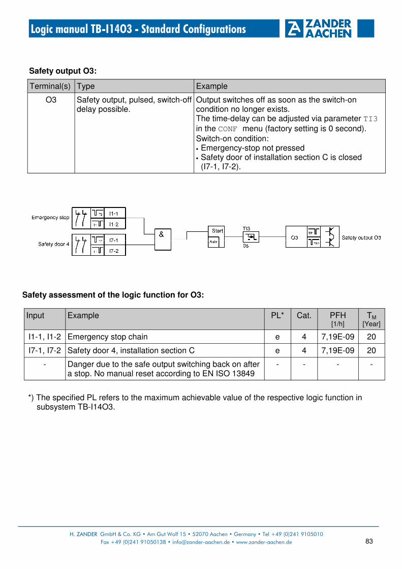
H. ZANDER GmbH & Co. KG • Am Gut Wolf 15 • 52070 Aachen • Germany • Tel +49 (0)241 9105010
Fax +49 (0)241 91050138 • [email protected] • www.zander-aachen.de 83
Logic manual TB-I14O3 - Standard Configurations
Safety output O3:
Safety assessment of the logic function for O3:
*) The specified PL refers to the maximum achievable value of the respective logic function in
subsystem TB-I14O3.
Terminal(s) Type Example
O3 Safety output, pulsed, switch-off delay possible.
Output switches off as soon as the switch-on condition no longer exists. The time-delay can be adjusted via parameter TI3 in the CONF menu (factory setting is 0 second). Switch-on condition: • Emergency-stop not pressed • Safety door of installation section C is closed
(I7-1, I7-2).
Input Example PL*
I1-1, I1-2 Emergency stop chain e
I7-1, I7-2 Safety door 4, installation section C e
- Danger due to the safe output switching back on after a stop. No manual reset according to EN ISO 13849
-
Cat.
4
4
-
PFH [1/h]
7,19E-09
7,19E-09
-
TM
[Year]
20
20
-

H. ZANDER GmbH & Co. KG • Am Gut Wolf 15 • 52070 Aachen • Germany • phone +49 (0)241 9105010
Fax +49 (0)241 91050138 • [email protected] • www.zander-aachen.de 84
Logic manual TB-I14O3 - Standard Configurations
3.8.6 Auxiliary outputs Auxiliary outputs C0..C3:
Auxiliary outputs C4..C5:
Terminal(s) Type Example
C0 Auxiliary output C0 is active, if safety door 1 of installation section A is closed (I2-1, I2-2).
C1 Auxiliary output C1 is active, if safety door 2 of installation section A is closed (I4-1, I4-2).
C2 Auxiliary output C2 is active, if safety door 3 of installation section B is closed (I6-1, I6-2).
C3 Auxiliary output C3 is active, if safety door 4 of installation section C is closed (I7-1, I7-2).
Terminal(s) Type Example
C4 Auxiliary output Auxiliary output for O1. Switch-on and switch-off conditions like O1, but non-delayed.
C5 Auxiliary output Auxiliary output for O2. Switch-on and switch-off conditions like O2, but non-delayed.

H. ZANDER GmbH & Co. KG • Am Gut Wolf 15 • 52070 Aachen • Germany • Tel +49 (0)241 9105010
Fax +49 (0)241 91050138 • [email protected] • www.zander-aachen.de 85
Logic manual TB-I14O3 - Standard Configurations
Flag definition for „M O1“ and „M O2“ in the function plans for O1 and O2.
3.8.7 Adjustable parameters
Parameter Value range Example
TI1 0..990 s (default: 0 s) Time delay for switch-off of the safety output O1.
TI2 0..990 s (default: 0 s) Time delay for switch-off of the safety output O2.
TI3 0..990 s (default: 0 s) Time delay for switch-off of the safety output O3.

H. ZANDER GmbH & Co. KG • Am Gut Wolf 15 • 52070 Aachen • Germany • phone +49 (0)241 9105010
Fax +49 (0)241 91050138 • [email protected] • www.zander-aachen.de 86
Logic manual TB-I14O3 - Standard Configurations
3.9 Standard Configuration PR07
3.9.1 Function:
• 3 independent safety outputs
• 5 non-contact safety switches (e.g. ZCode)
• 1 emergency stop
• 1 enable switch
• 1 start for the safety door circuit
• 1 start for the emergency stop circuit
• 1 start for the enable switch
3.9.2 Overview:
3.9.3 Function plan:
Quantity Type Description
7 FS-I 2-channel safety inputs with short circuit monitoring and difference time monitoring (same logic state within 3 seconds)
3 Start Inputs for start (monitored) and feedback loop (possible)
3 FS-O Safety outputs, pulsed
6 Aux Auxiliary outputs
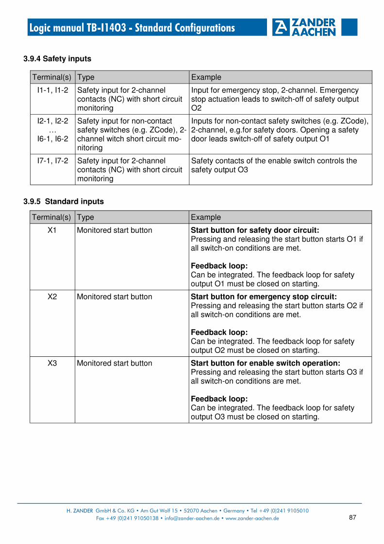
H. ZANDER GmbH & Co. KG • Am Gut Wolf 15 • 52070 Aachen • Germany • Tel +49 (0)241 9105010
Fax +49 (0)241 91050138 • [email protected] • www.zander-aachen.de 87
Logic manual TB-I14O3 - Standard Configurations
3.9.4 Safety inputs
3.9.5 Standard inputs
Terminal(s) Type Example
I1-1, I1-2 Safety input for 2-channel contacts (NC) with short circuit monitoring
Input for emergency stop, 2-channel. Emergency stop actuation leads to switch-off of safety output O2
I2-1, I2-2 …
I6-1, I6-2
Safety input for non-contact safety switches (e.g. ZCode), 2-channel witch short circuit mo-nitoring
Inputs for non-contact safety switches (e.g. ZCode), 2-channel, e.g.for safety doors. Opening a safety door leads switch-off of safety output O1
I7-1, I7-2 Safety input for 2-channel contacts (NC) with short circuit monitoring
Safety contacts of the enable switch controls the safety output O3
Terminal(s) Type Example
X1 Monitored start button Start button for safety door circuit: Pressing and releasing the start button starts O1 if all switch-on conditions are met. Feedback loop: Can be integrated. The feedback loop for safety output O1 must be closed on starting.
X2 Monitored start button Start button for emergency stop circuit: Pressing and releasing the start button starts O2 if all switch-on conditions are met. Feedback loop: Can be integrated. The feedback loop for safety output O2 must be closed on starting.
X3 Monitored start button Start button for enable switch operation: Pressing and releasing the start button starts O3 if all switch-on conditions are met. Feedback loop: Can be integrated. The feedback loop for safety output O3 must be closed on starting.

H. ZANDER GmbH & Co. KG • Am Gut Wolf 15 • 52070 Aachen • Germany • phone +49 (0)241 9105010
Fax +49 (0)241 91050138 • [email protected] • www.zander-aachen.de 88
Logic manual TB-I14O3 - Standard Configurations
3.9.6 Safety outputs Safety output O1:
Safety assessment of the logic function for O1:
*) The specified PL refers to the maximum achievable value of the respective logic function in subsystem TB-I14O3.
Terminal(s) Type Example
O1 Safety output, pulsed, switch-off delay possible.
Output switches off as soon as the switch-on condition no longer exists. The time-delay can be adjusted via parameter TI1 in the CONF menu (factory setting is 0 second). Switch-on condition: • All safety doors are closed (I2-1, I2-2 AND I3-1,
I3-2 AND I4-1, I4-2 AND I5-1, I5-2 AND I6-1, I6-2). • Press and release start button at X1
Input Example PL*
I2-1, I2-2 Safety door 1 e
I3-1, I3-2 Safety door 2 e
X1 Start button for safety door circuit c
I6-1, I6-2 Safety door 5 e
I5-1, I5-2 Safety door 4 e
I4-1, I4-2 Safety door 3 e
Cat.
4
4
4
4
4
1
PFH [1/h]
7,19E-09
7,19E-09
7,19E-09
7,19E-09
7,19E-09
1,15E-06
TM
[Year]
20
20
20
20
20
20

H. ZANDER GmbH & Co. KG • Am Gut Wolf 15 • 52070 Aachen • Germany • Tel +49 (0)241 9105010
Fax +49 (0)241 91050138 • [email protected] • www.zander-aachen.de 89
Logic manual TB-I14O3 - Standard Configurations
Safety output O2:
Safety assessment of the logic function for O2:
*) The specified PL refers to the maximum achievable value of the respective logic function in subsystem TB-I14O3.
Terminal(s) Type Example
O2 Safety output, pulsed, switch-off delay possible.
Output switches off as soon as the switch-on condition no longer exists. The time-delay can be adjusted via parameter TI2 in the CONF menu (factory setting is 0 second). Switch-on condition: • Emergency stop not pressed • Press and release start button at X2
Input Example PL*
I1-1, I1-2 Emergency stop chain e
X2 Start button for emergency stop chain c
Cat.
4
1
PFH [1/h]
7,19E-09
1,15E-06
TM
[Year]
20
20

H. ZANDER GmbH & Co. KG • Am Gut Wolf 15 • 52070 Aachen • Germany • phone +49 (0)241 9105010
Fax +49 (0)241 91050138 • [email protected] • www.zander-aachen.de 90
Logic manual TB-I14O3 - Standard Configurations
Safety output O3:
Safety assessment of the logic function for O3:
*) The specified PL refers to the maximum achievable value of the respective logic function in
subsystem TB-I14O3.
Terminal(s) Type Example
O3 Safety output, pulsed, switch-off delay possible.
Output switches off as soon as the switch-on condition no longer exists. The time-delay can be adjusted via parameter TI3 in the CONF menu (factory setting is 0 second). Switch-on condition: • Pressing enable switch • Press and release start button at X3
Input Example PL*
I7-1, I7-2 Enable switch e
X3 Start button for enable switch operation c
Cat.
4
1
PFH [1/h]
7,19E-09
1,15E-06
TM
[Year]
20
20

H. ZANDER GmbH & Co. KG • Am Gut Wolf 15 • 52070 Aachen • Germany • Tel +49 (0)241 9105010
Fax +49 (0)241 91050138 • [email protected] • www.zander-aachen.de 91
Logic manual TB-I14O3 - Standard Configurations
3.9.7 Auxiliary outputs Auxiliary output C0..C4:
Auxiliary output C5:
Flag definition for „M O1“ in the function plans for O1
Terminal(s) Type Example
C0 Auxiliary output C0 is active, if safety door 1 is closed (Safety door at I2-1, I2-2).
C1 Auxiliary output C1 is active, if safety door 2 is closed (Safety door at I3-1, I3-2).
C2 Auxiliary output C2 is active, if safety door 3 is closed (Safety door at I4-1, I4-2).
C3 Auxiliary output C3 is active, if safety door 4 is closed (Safety door at I5-1, I5-2).
C4 Auxiliary output C4 is active, if safety door 5 is closed (Safety door at I6-1, I6-2).
Terminal(s) Type Example
C5 Auxiliary output Auxiliary output for O1. Switch-on and switch-off conditions like O1, but non-delayed.

H. ZANDER GmbH & Co. KG • Am Gut Wolf 15 • 52070 Aachen • Germany • phone +49 (0)241 9105010
Fax +49 (0)241 91050138 • [email protected] • www.zander-aachen.de 92
Logic manual TB-I14O3 - Standard Configurations
3.9.8 Adjustable parameters
Parameter Value range Example
TI1 0..990 s (default: 0 s) Time delay for switch-off of the safety output O1.
TI2 0..990 s (default: 0 s) Time delay for switch-off of the safety output O2.
TI3 0..990 s (default: 0 s) Time delay for switch-off of the safety output O3.

H. ZANDER GmbH & Co. KG • Am Gut Wolf 15 • 52070 Aachen • Germany • Tel +49 (0)241 9105010
Fax +49 (0)241 91050138 • [email protected] • www.zander-aachen.de 93
Logic manual TB-I14O3 - Standard Configurations
3.10 Standard Configuration PR08
3.10.1 Function:
• 3 independent safety outputs
• 5 non-contact safety switches (e.g. ZCode)
• 1 emergency stop
• 1 enable switch
• 1 feedback loop for the safety door circuit
• 1 feedback loop for the emergency stop chain
• 1 start button for the enable switch
3.10.2 Overview:
3.10.3 Function plan:
Quantity Type Description
7 FS-I 2-channel safety inputs with short circuit monitoring and difference time monitoring (same logic state within 3 seconds)
2 Fl Feedback loop. With or without start button (non-monitored)
3 FS-O Safety outputs, pulsed
6 Aux Auxiliary outputs
1 Start Input for start (monitored) and feedback loop (possible)

H. ZANDER GmbH & Co. KG • Am Gut Wolf 15 • 52070 Aachen • Germany • phone +49 (0)241 9105010
Fax +49 (0)241 91050138 • [email protected] • www.zander-aachen.de 94
Logic manual TB-I14O3 - Standard Configurations
3.10.4 Safety inputs
3.10.5 Standard inputs
Terminal(s) Type Example
I1-1, I1-2 Safety input for 2-channel contacts (NC) with short circuit monitoring
Input for emergency stop, 2-channel. Emergency stop actuation leads to switch-off of safety output O2
I2-1, I2-2 …
I6-1, I6-2
Safety input for non-contact sa-fety swiches (e.g. ZCode), 2-channel witch short circuit mo-nitoring
Inputs for non-contact safety switches (e.g. ZCode), 2-channel, e.g.for safety doors. Opening a safety door leads switch-off of safety output O1
I7-1, I7-2 Safety input for 2-channel contacts (NC) with short circuit monitoring
Safety contacts of the enable switch controls the safety output O3
Terminal(s) Type Example
X1 Feedback loop Feedback loop for safety door circuit: The feedback loop for safety output O1 must be closed on starting. Start button can be integrated but is not monitored.
X2 Feedback loop Feedback loop for safety door circuit: The feedback loop for safety output O1 must be closed on starting. Start button can be integrated but is not monitored.
X3 Monitored start button Start button for enable switch operation: Pressing and releasing the start button starts O3 if all switch-on conditions are met. Feedback loop: Can be integrated. The feedback loop for safety output O3 must be closed on starting.

H. ZANDER GmbH & Co. KG • Am Gut Wolf 15 • 52070 Aachen • Germany • Tel +49 (0)241 9105010
Fax +49 (0)241 91050138 • [email protected] • www.zander-aachen.de 95
Logic manual TB-I14O3 - Standard Configurations
3.10.6 Safety outputs Safety output O1:
Safety assessment of the logic function for O1:
*) The specified PL refers to the maximum achievable value of the respective logic function in subsystem TB-I14O3.
Terminal(s) Type Example
O1 Safety output, pulsed, switch-off delay possible.
Output switches off as soon as the switch-on condition no longer exists. The time-delay can be adjusted via parameter TI1 in the CONF menu (factory setting is 0 second). Switch-on condition: • All safety doors are closed (I2-1, I2-2 AND I3-1,
I3-2 AND I4-1, I4-2 AND I5-1, I5-2 AND I6-1, I6-2). • Feedback loop at X1 is closed
Input Example PL*
I2-1, I2-2 Safety door 1 e
I3-1, I3-2 Safety door 2 e
X1 Feedback loop safety door c
I6-1, I6-2 Safety door 5 e
I5-1, I5-2 Safety door 4 e
I4-1, I4-2 Safety door 3 e
Cat.
4
4
4
4
4
1
PFH [1/h]
7,19E-09
7,19E-09
7,19E-09
7,19E-09
7,19E-09
1,15E-06
TM
[Year]
20
20
20
20
20
20

H. ZANDER GmbH & Co. KG • Am Gut Wolf 15 • 52070 Aachen • Germany • phone +49 (0)241 9105010
Fax +49 (0)241 91050138 • [email protected] • www.zander-aachen.de 96
Logic manual TB-I14O3 - Standard Configurations
Safety output O2:
Safety assessment of the logic function for O2: *) The specified PL refers to the maximum achievable value of the respective logic function in
subsystem TB-I14O3.
Terminal(s) Type Example
O2 Safety output, pulsed, switch-off delay possible.
Output switches off as soon as the switch-on condition no longer exists (factory setting is 0 se-cond). The time-delay can be adjusted via parameter TI2 in the CONF menu. Switch-on condition: • Emergency stop not pressed • Feedback loop at X2 is closed
Input Example PL*
I1-1, I1-2 Emergency stop chain e
X2 Feedback loop emergency stop c
Cat.
4
1
PFH [1/h]
7,19E-09
1,15E-06
TM
[Year]
20
20

H. ZANDER GmbH & Co. KG • Am Gut Wolf 15 • 52070 Aachen • Germany • Tel +49 (0)241 9105010
Fax +49 (0)241 91050138 • [email protected] • www.zander-aachen.de 97
Logic manual TB-I14O3 - Standard Configurations
Safety output O3:
Safety assessment of the logic function for O3: *) The specified PL refers to the maximum achievable value of the respective logic function in
subsystem TB-I14O3.
Terminal(s) Type Example
O3 Safety output, pulsed, switch-off delay possible.
Output switches off as soon as the switch-on condition no longer exists(factory setting is 0 se-cond). The time-delay can be adjusted via parameter TI3 in the CONF menu. Switch-on condition: • Pressing enable switch • Press and release start button at X3
Input Example PL*
I7-1, I7-2 Enable switch e
X3 Start button for enable switch operation c
Cat.
4
1
PFH [1/h]
7,19E-09
1,15E-06
TM
[Year]
20
20
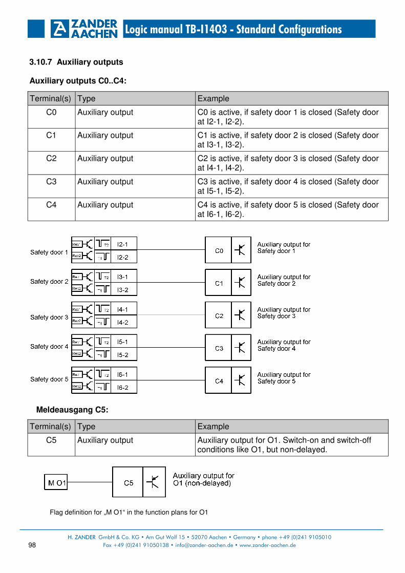
H. ZANDER GmbH & Co. KG • Am Gut Wolf 15 • 52070 Aachen • Germany • phone +49 (0)241 9105010
Fax +49 (0)241 91050138 • [email protected] • www.zander-aachen.de 98
Logic manual TB-I14O3 - Standard Configurations
3.10.7 Auxiliary outputs Auxiliary outputs C0..C4:
Meldeausgang C5:
Flag definition for „M O1“ in the function plans for O1
Terminal(s) Type Example
C0 Auxiliary output C0 is active, if safety door 1 is closed (Safety door at I2-1, I2-2).
C1 Auxiliary output C1 is active, if safety door 2 is closed (Safety door at I3-1, I3-2).
C2 Auxiliary output C2 is active, if safety door 3 is closed (Safety door at I4-1, I4-2).
C3 Auxiliary output C3 is active, if safety door 4 is closed (Safety door at I5-1, I5-2).
C4 Auxiliary output C4 is active, if safety door 5 is closed (Safety door at I6-1, I6-2).
Terminal(s) Type Example
C5 Auxiliary output Auxiliary output for O1. Switch-on and switch-off conditions like O1, but non-delayed.

H. ZANDER GmbH & Co. KG • Am Gut Wolf 15 • 52070 Aachen • Germany • Tel +49 (0)241 9105010
Fax +49 (0)241 91050138 • [email protected] • www.zander-aachen.de 99
Logic manual TB-I14O3 - Standard Configurations
3.10.8 Adjustable parameters
Parameter Value range Example
TI1 0..990 s (default: 0 s) Time delay for switch-off of the safety output O1.
TI2 0..990 s (default: 0 s) Time delay for switch-off of the safety output O2.
TI3 0..990 s (default: 0 s) Time delay for switch-off of the safety output O3.

H. ZANDER GmbH & Co. KG • Am Gut Wolf 15 • 52070 Aachen • Germany • phone +49 (0)241 9105010
Fax +49 (0)241 91050138 • [email protected] • www.zander-aachen.de 100
Logic manual TB-I14O3 - Standard Configurations
3.11 Standard Configuration PR09
3.11.1 Function:
• 3 independent safety outputs
• 5 non-contact safety switches (e.g. ZCode)
• 1 emergency stop
• 1 enable switch
• 1 start button for enable switch operation
3.11.2 Overview:
3.11.3 Function plan:
Quantity Type Description
7 FS-I 2-channel safety inputs with short circuit monitoring and difference time monitoring (same logic state within 3 seconds)
1 Start Inputs for start (monitored) and feedback loop (possible)
3 FS-O Safety outputs, pulsed
6 Aux Auxiliary outputs

H. ZANDER GmbH & Co. KG • Am Gut Wolf 15 • 52070 Aachen • Germany • Tel +49 (0)241 9105010
Fax +49 (0)241 91050138 • [email protected] • www.zander-aachen.de 101
Logic manual TB-I14O3 - Standard Configurations
3.11.4 Safety inputs
3.11.5 Standard inputs
Terminal(s) Type Example
I1-1, I1-2 Safety input for 2-channel contacts (NC) with short circuit monitoring
Input for emergency stop, 2-channel. Emergency stop actuation leads to switch-off of safety output O2
I2-1, I2-2 …
I6-1, I6-2
Safety input for non-contact safety switches (e.g. ZCode), 2-channel witch short circuit monitoring
Inputs for non-contact safety switches (e.g. ZCode), 2-channel, e.g. for safety doors. Opening a safety door leads switch-off of safety output O1
I7-1, I7-2 Safety input for 2-channel contacts (NC) with short circuit monitoring
Safety contacts of the enable switch controls the safety output O3
Terminal(s) Type Example
X3 Monitored start button Start button for enable switch operation Pressing and releasing the start button starts O3 if all switch-on conditions are met. Feedback loop: Can be integrated. The feedback loop for safety output O3 must be closed on starting.

H. ZANDER GmbH & Co. KG • Am Gut Wolf 15 • 52070 Aachen • Germany • phone +49 (0)241 9105010
Fax +49 (0)241 91050138 • [email protected] • www.zander-aachen.de 102
Logic manual TB-I14O3 - Standard Configurations
3.11.6 Safety outputs Safety output O1:
Safety assessment of the logic function for O1:
*) The specified PL refers to the maximum achievable value of the respective logic function in
subsystem TB-I14O3.
Terminal(s) Type Example
O1 Safety output, pulsed, switch-off delay possible.
Output switches off as soon as the switch-on condition no longer exists. The time-delay can be adjusted via parameter TI1 in the CONF menu (factory setting is 0 second). Switch-on condition: • All safety doors are closed (I2-1, I2-2 AND I3-1,
I3-2 AND I4-1, I4-2 AND I5-1, I5,2 AND I6-1, I6-2).
Input Example PL*
I2-1, I2-2 Safety door 1 e
I3-1, I3-2 Safety door 2 e
- Danger due to the safe output switching back on after a stop. No manual reset according to EN ISO 13849
-
I6-1, I6-2 Safety door 5 e
I5-1, I5-2 Safety door 4 e
I4-1, I4-2 Safety door 3 e
Cat.
4
4
4
4
4
-
PFH [1/h]
7,19E-09
7,19E-09
7,19E-09
7,19E-09
7,19E-09
-
TM
[Year]
20
20
20
20
20
-

H. ZANDER GmbH & Co. KG • Am Gut Wolf 15 • 52070 Aachen • Germany • Tel +49 (0)241 9105010
Fax +49 (0)241 91050138 • [email protected] • www.zander-aachen.de 103
Logic manual TB-I14O3 - Standard Configurations
Safety output O2:
Safety assessment of the logic function for O1:
*) The specified PL refers to the maximum achievable value of the respective logic function in subsystem TB-I14O3.
Terminal(s) Type Example
O2 Safety output, pulsed, switch-off delay possible.
Output switches off as soon as the switch-on condition no longer exists. The time-delay can be adjusted via parameter TI2 in the CONF menu (factory setting is 0 second). Switch-on condition: • Emergency stop not pressed
Input Example PL*
I1-1, I1-2 Emergency stop chain e
- Danger due to the safe output switching back on after a stop. No manual reset according to EN ISO 13849
-
Cat.
4
-
PFH [1/h]
7,19E-09
-
TM
[Year]
20
-

H. ZANDER GmbH & Co. KG • Am Gut Wolf 15 • 52070 Aachen • Germany • phone +49 (0)241 9105010
Fax +49 (0)241 91050138 • [email protected] • www.zander-aachen.de 104
Logic manual TB-I14O3 - Standard Configurations
Safety output O3:
Safety assessment of the logic function for O1:
*) The specified PL refers to the maximum achievable value of the respective logic function in
subsystem TB-I14O3.
Terminal(s) Type Example
O3 Safety output, pulsed, switch-off delay possible.
Output switches off as soon as the switch-on condition no longer exists. The time-delay can be adjusted via parameter TI3 in the CONF menu (factory setting is 0 second). Switch-on condition: • Pressing enable switch • Press and release start button at X3
Input Example PL*
I7-1, I7-2 Enable switch e
X3 Start button for enable switch operation c
Cat.
4
1
PFH [1/h]
7,19E-09
1,15E-06
TM
[Year]
20
20

H. ZANDER GmbH & Co. KG • Am Gut Wolf 15 • 52070 Aachen • Germany • Tel +49 (0)241 9105010
Fax +49 (0)241 91050138 • [email protected] • www.zander-aachen.de 105
Logic manual TB-I14O3 - Standard Configurations
3.11.7 Auxiliary outputs Auxiliary outputs C0..C4:
Auxiliary output C5:
Flag definition for „M O1“ in the function plans for O1
Terminal(s) Type Example
C0 Auxiliary output C0 is active, if safety door 1 is closed (Safety door at I2-1, I2-2).
C1 Auxiliary output C1 is active, if safety door 2 is closed (Safety door at I3-1, I3-2).
C2 Auxiliary output C2 is active, if safety door 3 is closed (Safety door at I4-1, I4-2).
C3 Auxiliary output C3 is active, if safety door 4 is closed (Safety door at I5-1, I5-2).
C4 Auxiliary output C4 is active, if safety door 5 is closed (Safety door at I6-1, I6-2).
Terminal(s) Type Example
C5 Auxiliary output Auxiliary output for O1. Switch-on and switch-off conditions like O1, but non-delayed.

H. ZANDER GmbH & Co. KG • Am Gut Wolf 15 • 52070 Aachen • Germany • phone +49 (0)241 9105010
Fax +49 (0)241 91050138 • [email protected] • www.zander-aachen.de 106
Logic manual TB-I14O3 - Standard Configurations
3.11.8 Adjustable parameters
Parameter Value range Example
TI1 0..990 s (default: 0 s) Time delay for switch-off of the safety output O1.
TI2 0..990 s (default: 0 s) Time delay for switch-off of the safety output O2.
TI3 0..990 s (default: 0 s) Time delay for switch-off of the safety output O3.
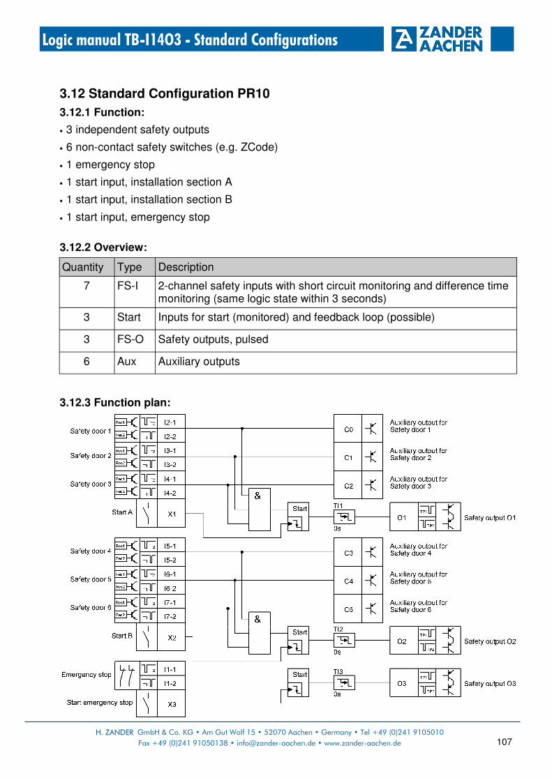
H. ZANDER GmbH & Co. KG • Am Gut Wolf 15 • 52070 Aachen • Germany • Tel +49 (0)241 9105010
Fax +49 (0)241 91050138 • [email protected] • www.zander-aachen.de 107
Logic manual TB-I14O3 - Standard Configurations
3.12 Standard Configuration PR10
3.12.1 Function:
• 3 independent safety outputs
• 6 non-contact safety switches (e.g. ZCode)
• 1 emergency stop
• 1 start input, installation section A
• 1 start input, installation section B
• 1 start input, emergency stop
3.12.2 Overview:
3.12.3 Function plan:
Quantity Type Description
7 FS-I 2-channel safety inputs with short circuit monitoring and difference time monitoring (same logic state within 3 seconds)
3 Start Inputs for start (monitored) and feedback loop (possible)
3 FS-O Safety outputs, pulsed
6 Aux Auxiliary outputs

H. ZANDER GmbH & Co. KG • Am Gut Wolf 15 • 52070 Aachen • Germany • phone +49 (0)241 9105010
Fax +49 (0)241 91050138 • [email protected] • www.zander-aachen.de 108
Logic manual TB-I14O3 - Standard Configurations
3.12.4 Safety inputs
3.12.5 Standard inputs
Terminal(s) Type Example
I1-1, I1-2 Safety input for 2-channel contacts (NC) with short circuit monitoring
Input for emergency stop, 2-channel. Emergency stop actuation leads to switch-off of safety output O3.
I2-1, I2-2 …
I4-1, I4-2
Safety input for non-contact safety switches (e.g. ZCode), 2-channel witch short circuit monitoring
Inputs for non-contact safety switches (e.g. ZCode), 2-channel, e.g.for safety doors. Opening a safety door leads switch-off of safety output O1.
I5-1, I5-2 …
I7-1, I7-2
Safety input for non-contact safety switches (e.g. ZCode), 2-channel witch short circuit monitoring
Inputs for non-contact safety switches (e.g. ZCode), 2-channel, e.g.for safety doors. Opening a safety door leads switch-off of safety output O2.
Terminal(s) Type Example
X1 Monitored start button Start button for installation section A: Pressing and releasing the start button starts O1 if all switch-on conditions are met. Feedback loop: Can be integrated. The feedback loop for safety output O1 must be closed on starting.
X2 Monitored start button Start button for installation section B: Pressing and releasing the start button starts O2 if all switch-on conditions are met. Feedback loop: Can be integrated. The feedback loop for safety output O2 must be closed on starting.
X3 Monitored start button Start button for emergency stop: Pressing and releasing the start button starts O3 if all switch-on conditions are met. Feedback loop: Can be integrated. The feedback loop for safety output O3 must be closed on starting.

H. ZANDER GmbH & Co. KG • Am Gut Wolf 15 • 52070 Aachen • Germany • Tel +49 (0)241 9105010
Fax +49 (0)241 91050138 • [email protected] • www.zander-aachen.de 109
Logic manual TB-I14O3 - Standard Configurations
3.12.6 Safety outputs Safety output O1:
Safety assessment of the logic function for O1:
*) The specified PL refers to the maximum achievable value of the respective logic function in subsystem TB-I14O3.
Terminal(s) Type Example
O1 Safety output, pulsed, switch-off delay possible.
Output switches off as soon as the switch-on condition no longer exists. The time-delay can be adjusted via parameter TI1 in the CONF menu (factory setting is 0 second). Switch-on condition: • Safety doors of installation section A are closed
(I2-1, I2-2 AND I3-1, I3-2 AND I4-1, I4-2). • Press and release start button at X1
Input Example PL*
I2-1, I2-2 Safety door 1 e
I3-1, I3-2 Safety door 2 e
I4-1, I4-2 Safety door 3 e
X1 Start button for installation section A c
Cat.
4
4
4
1
PFH [1/h]
7,19E-09
7,19E-09
7,19E-09
1,15E-06
TM
[Year]
20
20
20
20

H. ZANDER GmbH & Co. KG • Am Gut Wolf 15 • 52070 Aachen • Germany • phone +49 (0)241 9105010
Fax +49 (0)241 91050138 • [email protected] • www.zander-aachen.de 110
Logic manual TB-I14O3 - Standard Configurations
Safety output O2:
Safety assessment of the logic function for O2:
*) The specified PL refers to the maximum achievable value of the respective logic function in subsystem TB-I14O3.
Terminal(s) Type Example
O2 Safety output, pulsed, switch-off delay possible.
Output switches off as soon as the switch-on condition no longer exists. The time-delay can be adjusted via parameter TI2 in the CONF menu (factory setting is 0 second). Switch-on condition: • Safety doors of installation section B are closed
(I5-1, I5-2 AND I6-1, I6-2 AND I7-1, I7-2). • Press and release start button at X2
Input Example PL*
I5-1, I5-2 Safety door 4 e
I6-1, I6-2 Safety door 5 e
I7-1, I7-2 Safety door 6 e
X1 Start button for installation section B c
Cat.
4
4
4
1
PFH [1/h]
7,19E-09
7,19E-09
7,19E-09
1,15E-06
TM
[Year]
20
20
20
20

H. ZANDER GmbH & Co. KG • Am Gut Wolf 15 • 52070 Aachen • Germany • Tel +49 (0)241 9105010
Fax +49 (0)241 91050138 • [email protected] • www.zander-aachen.de 111
Logic manual TB-I14O3 - Standard Configurations
Safety output O3:
Safety assessment of the logic function for O3:
*) The specified PL refers to the maximum achievable value of the respective logic function in subsystem TB-I14O3.
Terminal(s) Type Example
O3 Safety output, pulsed, switch-off delay possible.
Output switches off as soon as the switch-on condition no longer exists. The time-delay can be adjusted via parameter TI3 in the CONF menu (factory setting is 0 second). Switch-on condition: • Emergency stop not pressed • Press and release start button at X3
Input Example PL*
I7-1, I7-2 Emergency stop e
X3 Start button for emergency stop c
Cat.
4
1
PFH [1/h]
7,19E-09
1,15E-06
TM
[Year]
20
20

H. ZANDER GmbH & Co. KG • Am Gut Wolf 15 • 52070 Aachen • Germany • phone +49 (0)241 9105010
Fax +49 (0)241 91050138 • [email protected] • www.zander-aachen.de 112
Logic manual TB-I14O3 - Standard Configurations
3.12.7 Auxiliary outputs Auxiliary outputs C0..C5:
Terminal(s) Type Example
C0 Auxiliary output C0 is active, if safety door 1 is closed (Safety door at I2-1, I2-2).
C1 Auxiliary output C1 is active, if safety door 2 is closed (Safety door at I3-1, I3-2).
C2 Auxiliary output C2 is active, if safety door 3 is closed (Safety door at I4-1, I4-2).
C3 Auxiliary output C3 is active, if safety door 4 is closed (Safety door at I5-1, I5-2).
C4 Auxiliary output C4 is active, if safety door 5 is closed (Safety door at I6-1, I6-2).
C5 Auxiliary output C5 is active, if safety door 6 is closed (Safety door at I7-1, I7-2).

H. ZANDER GmbH & Co. KG • Am Gut Wolf 15 • 52070 Aachen • Germany • Tel +49 (0)241 9105010
Fax +49 (0)241 91050138 • [email protected] • www.zander-aachen.de 113
Logic manual TB-I14O3 - Standard Configurations
3.12.8 Adjustable parameter
Parameter Value range Example
TI1 0..990 s (default: 0 s) Time delay for switch-off of the safety output O1.
TI2 0..990 s (default: 0 s) Time delay for switch-off of the safety output O2.
TI3 0..990 s (default: 0 s) Time delay for switch-off of the safety output O3.
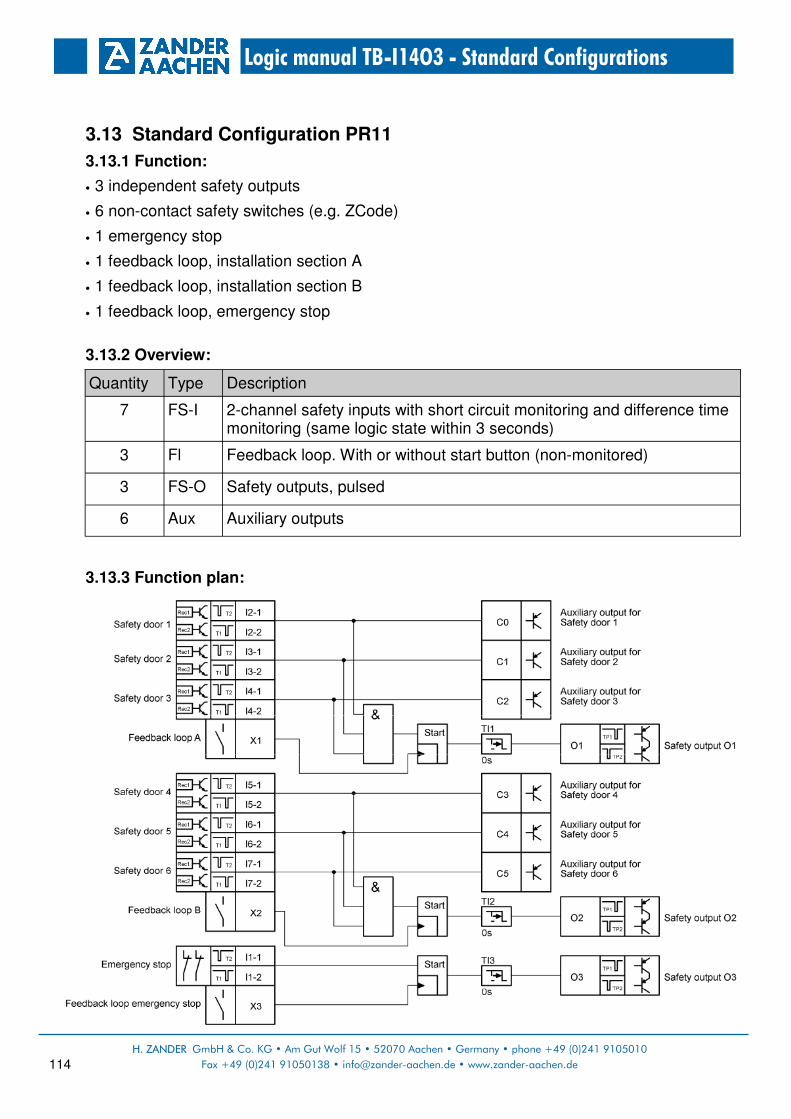
H. ZANDER GmbH & Co. KG • Am Gut Wolf 15 • 52070 Aachen • Germany • phone +49 (0)241 9105010
Fax +49 (0)241 91050138 • [email protected] • www.zander-aachen.de 114
Logic manual TB-I14O3 - Standard Configurations
3.13 Standard Configuration PR11
3.13.1 Function:
• 3 independent safety outputs
• 6 non-contact safety switches (e.g. ZCode)
• 1 emergency stop
• 1 feedback loop, installation section A
• 1 feedback loop, installation section B
• 1 feedback loop, emergency stop
3.13.2 Overview:
3.13.3 Function plan:
Quantity Type Description
7 FS-I 2-channel safety inputs with short circuit monitoring and difference time monitoring (same logic state within 3 seconds)
3 Fl Feedback loop. With or without start button (non-monitored)
3 FS-O Safety outputs, pulsed
6 Aux Auxiliary outputs
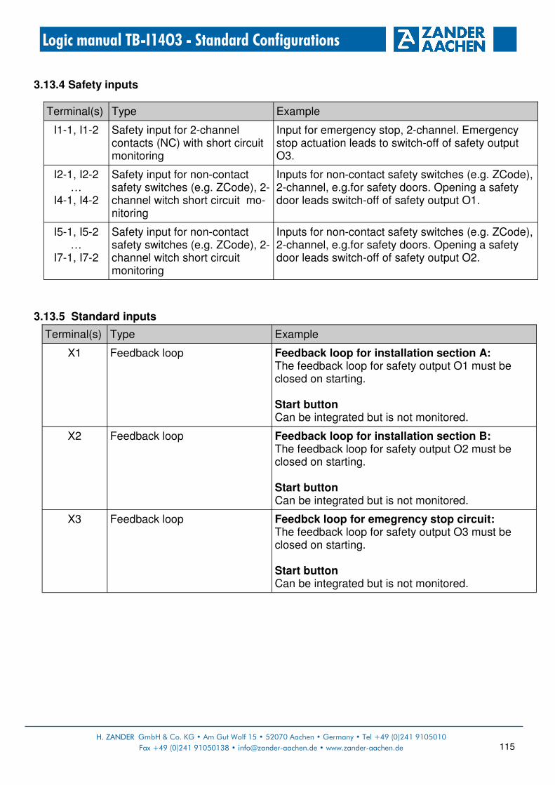
H. ZANDER GmbH & Co. KG • Am Gut Wolf 15 • 52070 Aachen • Germany • Tel +49 (0)241 9105010
Fax +49 (0)241 91050138 • [email protected] • www.zander-aachen.de 115
Logic manual TB-I14O3 - Standard Configurations
3.13.4 Safety inputs
3.13.5 Standard inputs
Terminal(s) Type Example
I1-1, I1-2 Safety input for 2-channel contacts (NC) with short circuit monitoring
Input for emergency stop, 2-channel. Emergency stop actuation leads to switch-off of safety output O3.
I2-1, I2-2 …
I4-1, I4-2
Safety input for non-contact safety switches (e.g. ZCode), 2-channel witch short circuit mo-nitoring
Inputs for non-contact safety switches (e.g. ZCode), 2-channel, e.g.for safety doors. Opening a safety door leads switch-off of safety output O1.
I5-1, I5-2 …
I7-1, I7-2
Safety input for non-contact safety switches (e.g. ZCode), 2-channel witch short circuit monitoring
Inputs for non-contact safety switches (e.g. ZCode), 2-channel, e.g.for safety doors. Opening a safety door leads switch-off of safety output O2.
Terminal(s) Type Example
X1 Feedback loop Feedback loop for installation section A: The feedback loop for safety output O1 must be closed on starting. Start button Can be integrated but is not monitored.
X2 Feedback loop Feedback loop for installation section B: The feedback loop for safety output O2 must be closed on starting. Start button Can be integrated but is not monitored.
X3 Feedback loop Feedbck loop for emegrency stop circuit: The feedback loop for safety output O3 must be closed on starting. Start button Can be integrated but is not monitored.

H. ZANDER GmbH & Co. KG • Am Gut Wolf 15 • 52070 Aachen • Germany • phone +49 (0)241 9105010
Fax +49 (0)241 91050138 • [email protected] • www.zander-aachen.de 116
Logic manual TB-I14O3 - Standard Configurations
3.13.6 Safety outputs Safety output O1:
Safety assessment of the logic function for O1:
*) The specified PL refers to the maximum achievable value of the respective logic function in
subsystem TB-I14O3.
Terminal(s) Type Example
O1 Safety output, pulsed, switch-off delay possible.
Output switches off as soon as the switch-on condition no longer exists. The time-delay can be adjusted via parameter TI1 in the CONF menu (factory setting is 0 second). Switch-on condition: • Safety doors for installation section A are closed
(I2-1, I2-2 AND I3-1, I3-2 AND I4-1, I4-2) • Feedback loop at X1 is closed
Input Example PL*
I2-1, I2-2 Safety door 1 e
I3-1, I3-2 Safety door 2 e
I4-1, I4-2 Safety door 3 e
X1 Feedback loop for installation section A c
Cat.
4
4
4
1
PFH [1/h]
7,19E-09
7,19E-09
7,19E-09
1,15E-06
TM
[Year]
20
20
20
20

H. ZANDER GmbH & Co. KG • Am Gut Wolf 15 • 52070 Aachen • Germany • Tel +49 (0)241 9105010
Fax +49 (0)241 91050138 • [email protected] • www.zander-aachen.de 117
Logic manual TB-I14O3 - Standard Configurations
Safety output O2:
Safety assessment of the logic function for O2:
*) The specified PL refers to the maximum achievable value of the respective logic function in subsystem TB-I14O3.
Terminal(s) Type Example
O2 Safety output, pulsed, switch-off delay possible.
Output switches off as soon as the switch-on condition no longer exists. The time-delay can be adjusted via parameter TI2 in the CONF menu (factory setting is 0 second). • Safety doors for installation section B are closed
(I5-1, I5-2 AND I6-1, I6-2 AND I7-1, I7-2) • Feedback loop at X2 is closed
Input Example PL*
I5-1, I5-2 Safety door 4 e
I6-1, I6-2 Safety door 5 e
I7-1, I7-2 Safety door 6 e
X2 Feedback loop for installation section B c
Cat.
4
4
4
1
PFH [1/h]
7,19E-09
7,19E-09
7,19E-09
1,15E-06
TM
[Year]
20
20
20
20

H. ZANDER GmbH & Co. KG • Am Gut Wolf 15 • 52070 Aachen • Germany • phone +49 (0)241 9105010
Fax +49 (0)241 91050138 • [email protected] • www.zander-aachen.de 118
Logic manual TB-I14O3 - Standard Configurations
Safety output O3:
Safety assessment of the logic function for O3:
*) The specified PL refers to the maximum achievable value of the respective logic function in subsystem TB-I14O3.
Terminal(s) Type Example
O3 Safety output, pulsed, switch-off delay possible.
Output switches off as soon as the switch-on condition no longer exists. The time-delay can be adjusted via parameter TI3 in the CONF menu (factory setting is 0 second). • Emergency stop not pressed • Feedback loop at X3 ist closed
Input Example PL*
I7-1, I7-2 Emergency stop e
X3 Feedback loop for emergency stop c
Cat.
4
1
PFH [1/h]
7,19E-09
1,15E-06
TM
[Year]
20
20

H. ZANDER GmbH & Co. KG • Am Gut Wolf 15 • 52070 Aachen • Germany • Tel +49 (0)241 9105010
Fax +49 (0)241 91050138 • [email protected] • www.zander-aachen.de 119
Logic manual TB-I14O3 - Standard Configurations
3.13.7 Auxiliary outputs Auxiliary outputs C0..C5:
Terminal(s) Type Example
C0 Auxiliary output C0 is active, if safety door 1 is closed (Safety door at I2-1, I2-2).
C1 Auxiliary output C1 is active, if safety door 2 is closed (Safety door at I3-1, I3-2).
C2 Auxiliary output C2 is active, if safety door 3 is closed (Safety door at I4-1, I4-2).
C3 Auxiliary output C3 is active, if safety door 4 is closed (Safety door at I5-1, I5-2).
C4 Auxiliary output C4 is active, if safety door 5 is closed (Safety door at I6-1, I6-2).
C5 Auxiliary output C5 is active, if safety door 6 is closed (Safety door at I7-1, I7-2).

H. ZANDER GmbH & Co. KG • Am Gut Wolf 15 • 52070 Aachen • Germany • phone +49 (0)241 9105010
Fax +49 (0)241 91050138 • [email protected] • www.zander-aachen.de 120
Logic manual TB-I14O3 - Standard Configurations
3.13.8 Adjustable parameters
Parameter Value range Example
TI1 0..990 s (default: 0 s) Time delay for switch-off of the safety output O1.
TI2 0..990 s (default: 0 s) Time delay for switch-off of the safety output O2.
TI3 0..990 s (default: 0 s) Time delay for switch-off of the safety output O3.

H. ZANDER GmbH & Co. KG • Am Gut Wolf 15 • 52070 Aachen • Germany • Tel +49 (0)241 9105010
Fax +49 (0)241 91050138 • [email protected] • www.zander-aachen.de 121
Logic manual TB-I14O3 - Standard Configurations
3.14 Standard Configuration PR12
3.14.1 Function:
• 3 independent safety outputs
• 6 non-contact safety switches (e.g. ZCode)
• 1 emergency stop
3.14.2 Overview:
3.14.3 Function plan:
Quantity Type Description
7 FS-I 2-channel safety inputs with short circuit monitoring and difference time monitoring (same logic state within 3 seconds)
3 FS-O Safety outputs, pulsed
6 Aux Auxiliary outputs

H. ZANDER GmbH & Co. KG • Am Gut Wolf 15 • 52070 Aachen • Germany • phone +49 (0)241 9105010
Fax +49 (0)241 91050138 • [email protected] • www.zander-aachen.de 122
Logic manual TB-I14O3 - Standard Configurations
3.14.4 Safety inputs
Terminal(s) Type Example
I1-1, I1-2 Safety input for 2-channel contacts (NC) with short circuit monitoring
Input for emergency stop, 2-channel. Emergency stop actuation leads to switch-off of safety output O3.
I2-1, I2-2 …
I4-1, I4-2
Safety input for non-contact safety switches (e.g. ZCode), 2-channel witch short circuit monitoring
Inputs for non-contact safety switches (e.g. ZCode), 2-channel, e.g.for safety doors. Opening a safety door leads switch-off of safety output O1.
I5-1, I5-2 …
I7-1, I7-2
Safety input for non-contact safety switches (e.g. ZCode), 2-channel witch short circuit monitoring
Inputs for non-contact safety switches (e.g. ZCode), 2-channel, e.g.for safety doors. Opening a safety door leads switch-off of safety output O2.

H. ZANDER GmbH & Co. KG • Am Gut Wolf 15 • 52070 Aachen • Germany • Tel +49 (0)241 9105010
Fax +49 (0)241 91050138 • [email protected] • www.zander-aachen.de 123
Logic manual TB-I14O3 - Standard Configurations
3.14.5 Safety outputs Safety output O1:
Safety assessment of the logic function for O1:
*) The specified PL refers to the maximum achievable value of the respective logic function in subsystem TB-I14O3.
Terminal(s) Type Example
O1 Safety output, pulsed, switch-off delay possible.
Output switches off as soon as the switch-on condition no longer exists. The time-delay can be adjusted via parameter TI1 in the CONF menu (factory setting is 0 second). Switch-on condition: • Safety door for installation section A are closed
(I2-1, I2-2 UND I3-1, I3-2 UND I4-1, I4-2).
Input Example PL*
I2-1, I2-2 Safety door 1 e
I3-1, I3-2 Safety door 2 e
I4-1, I4-2 Safety door 3 e
- Danger due to the safe output switching back on after a stop. No manual reset according to EN ISO 13849
-
Cat.
4
4
4
-
PFH [1/h]
7,19E-09
7,19E-09
7,19E-09
-
TM
[Year]
20
20
20
-

H. ZANDER GmbH & Co. KG • Am Gut Wolf 15 • 52070 Aachen • Germany • phone +49 (0)241 9105010
Fax +49 (0)241 91050138 • [email protected] • www.zander-aachen.de 124
Logic manual TB-I14O3 - Standard Configurations
Safety output O2:
Safety assessment of the logic function for O2:
*) The specified PL refers to the maximum achievable value of the respective logic function in subsystem TB-I14O3.
Terminal(s) Type Example
O2 Safety output, pulsed, switch-off delay possible.
Output switches off as soon as the switch-on condition no longer exists. The time-delay can be adjusted via parameter TI2 in the CONF menu (factory setting is 0 second). Switch-on condition: • Safety doors for installation section B are closed
(I5-1, I5-2 UND I6-1, I6-2 UND I7-1, I7-2).
Input Example PL*
I5-1, I5-2 Safety door 4 e
I6-1, I6-2 Safety door 5 e
I7-1, I7-2 Safety door 6 e
- Danger due to the safe output switching back on after a stop. No manual reset according to EN ISO 13849
-
Cat.
4
4
4
-
PFH [1/h]
7,19E-09
7,19E-09
7,19E-09
-
TM
[Year]
20
20
20
-

H. ZANDER GmbH & Co. KG • Am Gut Wolf 15 • 52070 Aachen • Germany • Tel +49 (0)241 9105010
Fax +49 (0)241 91050138 • [email protected] • www.zander-aachen.de 125
Logic manual TB-I14O3 - Standard Configurations
Safety output O3:
Safety assessment of the logic function for O3:
*) The specified PL refers to the maximum achievable value of the respective logic function in
subsystem TB-I14O3.
Terminal(s) Type Example
O3 Safety output, pulsed, switch-off delay possible.
Output switches off as soon as the switch-on condition no longer exists. The time-delay can be adjusted via parameter TI3 in the CONF menu (factory setting is 0 second). Switch-on condition: • Emergency stop not pressed
Input Example PL*
I7-1, I7-2 Emergency stop e
- Danger due to the safe output switching back on after a stop. No manual reset according to EN ISO 13849
-
Cat.
4
-
PFH [1/h]
7,19E-09
-
TM
[Year]
20
-

H. ZANDER GmbH & Co. KG • Am Gut Wolf 15 • 52070 Aachen • Germany • phone +49 (0)241 9105010
Fax +49 (0)241 91050138 • [email protected] • www.zander-aachen.de 126
Logic manual TB-I14O3 - Standard Configurations
3.14.6 Auxiliary outputs Auxiliary outputs C0..C5:
Terminal(s) Type Example
C0 Auxiliary output C0 is active, if safety door 1 is closed (Safety door at I2-1, I2-2).
C1 Auxiliary output C1 is active, if safety door 2 is closed (Safety door at I3-1, I3-2).
C2 Auxiliary output C2 is active, if safety door 3 is closed (Safety door at I4-1, I4-2).
C3 Auxiliary output C3 is active, if safety door 4 is closed (Safety door at I5-1, I5-2).
C4 Auxiliary output C4 is active, if safety door 5 is closed (Safety door at I6-1, I6-2).
C5 Auxiliary output C5 is active, if safety door 6 is closed (Safety door at I7-1, I7-2).
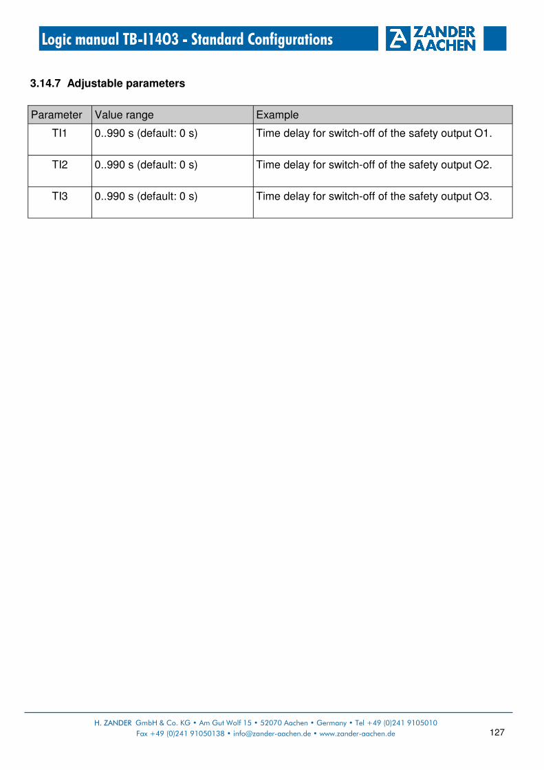
H. ZANDER GmbH & Co. KG • Am Gut Wolf 15 • 52070 Aachen • Germany • Tel +49 (0)241 9105010
Fax +49 (0)241 91050138 • [email protected] • www.zander-aachen.de 127
Logic manual TB-I14O3 - Standard Configurations
3.14.7 Adjustable parameters
Parameter Value range Example
TI1 0..990 s (default: 0 s) Time delay for switch-off of the safety output O1.
TI2 0..990 s (default: 0 s) Time delay for switch-off of the safety output O2.
TI3 0..990 s (default: 0 s) Time delay for switch-off of the safety output O3.

H. ZANDER GmbH & Co. KG • Am Gut Wolf 15 • 52070 Aachen • Germany • phone +49 (0)241 9105010
Fax +49 (0)241 91050138 • [email protected] • www.zander-aachen.de 128
Logic manual TB-I14O3 - Standard Configurations
3.15 Standard Configuration PR13
3.15.1 Function:
• 3 safety outputs (2 of them are dependent according delay time)
• 1 joint emergency stop
• 5 non-contact safety switches (e.g. ZCode), e.g. for safety doors
• 1 operation mode switch
• 1 start input automatic operation
• 1 start input manual operation
3.15.2 Overview:
3.15.3 Function plan:
Quantity Type Description
7 FS-I 2-channel safety inputs with short circuit monitoring and difference time monitoring (same logic state within 3 seconds)
2 Start Inputs for start (monitored) and feedback loop (possible)
2 FS-O Safety outputs, pulse, non-delayed
6 Aux Auxiliary outputs
1 FS-O Safety output, pulsed, delayed

H. ZANDER GmbH & Co. KG • Am Gut Wolf 15 • 52070 Aachen • Germany • Tel +49 (0)241 9105010
Fax +49 (0)241 91050138 • [email protected] • www.zander-aachen.de 129
Logic manual TB-I14O3 - Standard Configurations
3.15.4 Safety inputs
3.15.5 Standard inputs
Terminal(s) Type Example
I1-1, I1-2 Safety input for 2-channel contacts (NC) with short circuit monitoring
Input for emergency stop chain, 2-channel. Emergency stop actuation generally leads to switch-off of all safety outputs.
I2-1, I2-2 …
I5-1, I5-2
Safety input for non-contact safety switches (e.g. ZCode), 2-channel with short circuit monitoring
Inputs for non-contact safety switches (e.g. ZCode), 2-channel, e.g. for safety doors. Opening a safety door leads to switch-off of the safety output O1.
I6-1, I6-2 Safety input for non-contact safety switches (e.g. ZCode), 2-channel with short circuit monitoring
Separate safety door circuit to hedge maintanence.
I7-1, I7-2 Safety input for 2-channel contacts (NC) with short circuit monitoring
Input for safety switch, 2-channel (key switch) to release operation mode „manual“ Conditions: Contacts open: „automatic operation“ Contacts closed: „manual operation“
Terminal(s) Type Example
X1 Monitored start button Start button for „automatic operation“ Pressing and releasing the start button starts O1 and O2 if all switch-on conditions are met. Feedback loop: Can be integrated. The feedback loop for safety output O1/O2 must be closed on starting.
X2 Monitored start button Start button for „manual operation“: Pressing and releasing the start button starts O3 if all switch-on conditions are met. Feedback loop: Can be integrated. The feedback loop for safety output O3 must be closed on starting.

H. ZANDER GmbH & Co. KG • Am Gut Wolf 15 • 52070 Aachen • Germany • phone +49 (0)241 9105010
Fax +49 (0)241 91050138 • [email protected] • www.zander-aachen.de 130
Logic manual TB-I14O3 - Standard Configurations
3.15.6 Safety outputs Safety output O1:
Safety assessment of the logic function for O1:
*) The specified PL refers to the maximum achievable value of the respective logic function in subsystem TB-I14O3.
Terminal(s) Type Example
O1 Safety output, non-delayed, pulsed
Output switches off as soon as the switch-on condition no longer exists. Switch-on condition: • Emergency stop not pressed • Safety doors for „automatic operation“ are closed
(I2-1, I2-2 AND I3-1, I3-2 AND I4-1, I4-2 AND I5-1, I5-2).
• Operation mode switch set to „automatic operation“
• Press and release start button at X1
Input Example PL*
I1-1, I1-2 Emergency stop e
I2-1, I2-2 Safety door 1 e
I3-1, I3-2 Safety door 2 e
X1 Start button for „automatic operation“ c
I5-1, I5-2 Safety door 4 e
I4-1, I4-2 Safety door 3 e
I7-1, I7-2 Operation mode switch The main task of a operation mode switch is to en-sure that only one operation can be active. The selection of a particular mode of operation is not monitored. Pay attention to further demands on the operation mode switch according to the Machinery Directive 2006/42 / EC App. I, Sect. 1.2.5
e
Cat.
4
4
4
4
4
4
1
PFH [1/h]
7,19E-09
7,19E-09
7,19E-09
7,19E-09
7,19E-09
7,19E-09
1,15E-06
TM
[Year]
20
20
20
20
20
20
20

H. ZANDER GmbH & Co. KG • Am Gut Wolf 15 • 52070 Aachen • Germany • Tel +49 (0)241 9105010
Fax +49 (0)241 91050138 • [email protected] • www.zander-aachen.de 131
Logic manual TB-I14O3 - Standard Configurations
Safety output O2:
Safety assessment of the logic function for O2:
*) The specified PL refers to the maximum achievable value of the respective logic function in subsystem TB-I14O3.
Terminal(s) Type Example
O2 Safety output, delay, pulsed
Output switches off as soon as the switch-on condition no longer exists. The time-delay can be adjusted via parameter TI2 in the CONF menu (factory setting is 1 second). Switch-on condition: • Emergency stop not pressed • Safety doors for „automatic operatio“ are closed
(I2-1, I2-2 AND I3-1, I3-2 AND I4-1, I4-2 AND I5-1, I5-2).
• Operation mode switch set to „automatic operation“
• Press and release start button at X1
Input Example PL*
I1-1, I1-2 Emergency stop e
I2-1, I2-2 Safety door 1 e
I3-1, I3-2 Safety door 2 e
X1 Start button for „automatic operation“ c
I5-1, I5-2 Safety door 4 e
I4-1, I4-2 Safety door 3 e
I7-1, I7-2 Operation mode switch The main task of a operation mode switch is to ensure that only one operation can be active. The selection of a particular mode of operation is not monitored. Pay attention to further demands on the operation mode switch according to the Machinery Directive 2006/42 / EC App. I, Sect. 1.2.5
e
Cat.
4
4
4
4
4
4
1
PFH [1/h]
7,19E-09
7,19E-09
7,19E-09
7,19E-09
7,19E-09
7,19E-09
1,15E-06
TM
[Year]
20
20
20
20
20
20
20

H. ZANDER GmbH & Co. KG • Am Gut Wolf 15 • 52070 Aachen • Germany • phone +49 (0)241 9105010
Fax +49 (0)241 91050138 • [email protected] • www.zander-aachen.de 132
Logic manual TB-I14O3 - Standard Configurations
Safety output O3:
Safety assessment of the logic function for O3:
*) The specified PL refers to the maximum achievable value of the respective logic function in
subsystem TB-I14O3.
Terminal(s) Type Example
O3 Safety output, non-delayed, pulsed
Output switches off as soon as the switch-on condition no longer exists. Switch-on condition: • Emergency stop not pressed • Safety door 4 is closed (I5-1, I5-2) • Safety switch is closed (I6-1, I6-2) • Operation mode switch set to „manual operation“ • Press and release start button at X2
Input Example PL*
I1-1, I1-2 Emergency stop e
I5-1, I5-2 Safety door 4 e
I6-1, I6-2 Mech. safety switch e
I7-1, I7-2 Operation mode switch The main task of a operation mode switch is to en-sure that only one operation can be active. The selec-tion of a particular mode of operation is not monito-red. Pay attention to further demands on the operati-on mode switch according to the Machinery Directive 2006/42 / EC App. I, Sect. 1.2.5
e
X2 Start button for „manual operation“ c
Cat.
4
4
4
4
1
PFH [1/h]
7,19E-09
7,19E-09
7,19E-09
7,19E-09
1,15E-06
TM
[Year]
20
20
20
20
20

H. ZANDER GmbH & Co. KG • Am Gut Wolf 15 • 52070 Aachen • Germany • Tel +49 (0)241 9105010
Fax +49 (0)241 91050138 • [email protected] • www.zander-aachen.de 133
Logic manual TB-I14O3 - Standard Configurations
3.15.7 Auxiliary outputs Auxiliary outputs C0..C2:
Terminal(s) Type Example
C0 Auxiliary outputs C0 is active, if the emergency stop is not pressed.
C1 Auxiliary outputs C1 is active, if the emergency stop is not pressed AND safety door 1..4 are closed AND the operation mode switch is set to „automatic operation“.
C2 Auxiliary outputs C2 is active, if the emergency stop circuit is not pressed AND the safety door 4 is closed AND the mech. safety switch is closed AND the operation mode switch is set to „manual operation“.

H. ZANDER GmbH & Co. KG • Am Gut Wolf 15 • 52070 Aachen • Germany • phone +49 (0)241 9105010
Fax +49 (0)241 91050138 • [email protected] • www.zander-aachen.de 134
Logic manual TB-I14O3 - Standard Configurations
Flag definition for „M O1“, „M O2“ and „M O3“ in the function plans for O1, O2 and O3.
3.15.8 Adjustable parameters
Parameter Value range Example
TI2 0..990 s (default: 0 s) Time delay for switch-off of the safety output O2.
Terminal(s) Type Example
C3 Auxiliary output Auxiliary output for O1. Switch-on and switch-off conditions like O1, but non-delayed.
C4 Auxiliary output Auxiliary output for O2. Switch-on and switch-off conditions like O2, but non-delayed.
C5 Auxiliary output Auxiliary output for O3. Switch-on and switch-off conditions like O3, but non-delayed.
Auxiliary outputs C3..C5:

H. ZANDER GmbH & Co. KG • Am Gut Wolf 15 • 52070 Aachen • Germany • Tel +49 (0)241 9105010
Fax +49 (0)241 91050138 • [email protected] • www.zander-aachen.de 135
Logic manual TB-I14O3 - Standard Configurations
3.16 Standard Configuration PR14
3.16.1 Function:
• 3 safety outputs. Each has the same switch-on condition. For two of them, the switch-off
delay time can be parameterized.
• 1 safety output Group signal
• 5 non-contact safety switches (e.g. ZCode)
• 1 emergency stop
• 1 safety input Group signal
• 1 start for all safety outputs
3.16.2 Overview:
3.16.3 Function plan:
Quantity Type Description
6 FS-I 2-channel safety inputs with short circuit monitoring and difference time monitoring (same logic state within 3 seconds)
1 Grp-I Safety input, 2-channel for Group signal with short circuit monitoring and difference time monitoring (same logic state within 3 seconds“
3 FS-O Safety outputs, pulsed
4 Aux Auxiliary outputs
1 Grp-O Safety outputs, pulsed for Group signal
1 Start Input for start (monitored) and feedback loop (possible)

H. ZANDER GmbH & Co. KG • Am Gut Wolf 15 • 52070 Aachen • Germany • phone +49 (0)241 9105010
Fax +49 (0)241 91050138 • [email protected] • www.zander-aachen.de 136
Logic manual TB-I14O3 - Standard Configurations
3.16.4 Safety inputs
3.16.5 Standard inputs
Terminal(s) Type Example
I1-1, I1-2 Safety input for 2-channel contacts (NC) with short circuit monitoring
Input for emergency stop chain, 2-channel. Emergency stop actuation generally leads to switch-off of all safety outputs and the Group signal output.
I2-1, I2-2 …
I6-1, I6-2
Safety input for non-contact safety switches (e.g. ZCode), 2-channel witch short circuit monitoring
Inputs for non-contact safety switches (e.g. ZCode), 2-channel, e.g. for safety doors. Opening a safety door leads to switch-off of all safety outputs.
I7-1, I7-2 Safety input for Group signal, 2-channel (Group signal output from another TB-I14O3) with short circuit monitoring
Input to connect two TB-I14O3. A switch-off of the Group signal leads to switch-off of all safety outputs and the Group signal output.
Terminal(s) Type Example
X1 Monitored start button Start button safety door circuit Pressing and releasing the start button starts O1, O2 and O3 if all switch-on conditions are met. Feedback loop: Can be integrated. The feedback loop for safety output O1, O2 and O3 must be closed on starting.

H. ZANDER GmbH & Co. KG • Am Gut Wolf 15 • 52070 Aachen • Germany • Tel +49 (0)241 9105010
Fax +49 (0)241 91050138 • [email protected] • www.zander-aachen.de 137
Logic manual TB-I14O3 - Standard Configurations
3.16.6 Safety outputs Safety output O1:
Safety assessment of the logic function for O1:
*) The specified PL refers to the maximum achievable value of the respective logic function in subsystem TB-I14O3.
Terminal(s) Type Example
O1 Safety output, pulsed, non-delayed
Output switches off as soon as the switch-on condition no longer exists. Switch-on condition: • Emergency stop not pressed (I1-1, I1-2) • All safety doors are closed (I2-1, I2-2 AND I3-1,
I3-2 AND I4-1, I4-2 AND I5-1, I5-2 AND I6-1, I6-2). • Group signal is active (I7-1, I7-2) • Press and release start button at X1
Input Example PL*
I2-1, I2-2 Safety door 1 e
I3-1, I3-2 Safety door 2 e
X1 Start button c
I6-1, I6-2 Safety door 5 e
I5-1, I5-2 Safety door 4 e
I4-1, I4-2 Safety door 3 e
I1-1, I1-2 Emergency stop e
I7-1, I7-2 Group signal e
Cat.
4
4
4
4
4
4
4
1
PFH [1/h]
7,19E-09
7,19E-09
7,19E-09
7,19E-09
7,19E-09
7,19E-09
7,19E-09
1,15E-06
TM
[Year]
20
20
20
20
20
20
20
20
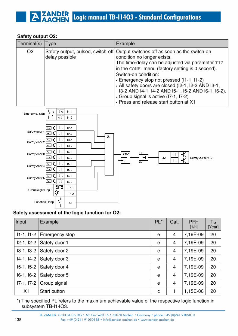
H. ZANDER GmbH & Co. KG • Am Gut Wolf 15 • 52070 Aachen • Germany • phone +49 (0)241 9105010
Fax +49 (0)241 91050138 • [email protected] • www.zander-aachen.de 138
Logic manual TB-I14O3 - Standard Configurations
Safety output O2:
Safety assessment of the logic function for O2:
*) The specified PL refers to the maximum achievable value of the respective logic function in subsystem TB-I14O3.
Terminal(s) Type Example
O2 Safety output, pulsed, switch-off delay possible
Output switches off as soon as the switch-on condition no longer exists. The time-delay can be adjusted via parameter TI2 in the CONF menu (factory setting is 0 second). Switch-on condition: • Emergency stop not pressed (I1-1, I1-2) • All safety doors are closed (I2-1, I2-2 AND I3-1,
I3-2 AND I4-1, I4-2 AND I5-1, I5-2 AND I6-1, I6-2). • Group signal is active (I7-1, I7-2) • Press and release start button at X1
Input Example PL*
I2-1, I2-2 Safety door 1 e
I3-1, I3-2 Safety door 2 e
X1 Start button c
I6-1, I6-2 Safety door 5 e
I5-1, I5-2 Safety door 4 e
I4-1, I4-2 Safety door 3 e
I1-1, I1-2 Emergency stop e
I7-1, I7-2 Group signal e
Cat.
4
4
4
4
4
4
4
1
PFH [1/h]
7,19E-09
7,19E-09
7,19E-09
7,19E-09
7,19E-09
7,19E-09
7,19E-09
1,15E-06
TM
[Year]
20
20
20
20
20
20
20
20

H. ZANDER GmbH & Co. KG • Am Gut Wolf 15 • 52070 Aachen • Germany • Tel +49 (0)241 9105010
Fax +49 (0)241 91050138 • [email protected] • www.zander-aachen.de 139
Logic manual TB-I14O3 - Standard Configurations
Safety output O3:
Safety assessment of the logic function for O3:
*) The specified PL refers to the maximum achievable value of the respective logic function in subsystem TB-I14O3.
Terminal(s) Type Example
O3 Safety output, pulsed, switch-off delay possible
Output switches off as soon as the switch-on condition no longer exists. The time-delay can be adjusted via parameter TI3 in the CONF menu (factory setting is 0 second). Switch-on condition: • Emergency stop not pressed (I1-1, I1-2) • All safety doors are closed (I2-1, I2-2 AND I3-1,
I3-2 AND I4-1, I4-2 AND I5-1, I5-2 AND I6-1, I6-2). • Group signal is active (I7-1, I7-2) • Press and release start button at X1
Input Example PL*
I2-1, I2-2 Safety door 1 e
I3-1, I3-2 Safety door 2 e
X1 Start button c
I6-1, I6-2 Safety door 5 e
I5-1, I5-2 Safety door 4 e
I4-1, I4-2 Safety door 3 e
I1-1, I1-2 Emergency stop e
I7-1, I7-2 Group signal e
Cat.
4
4
4
4
4
4
4
1
PFH [1/h]
7,19E-09
7,19E-09
7,19E-09
7,19E-09
7,19E-09
7,19E-09
7,19E-09
1,15E-06
TM
[Year]
20
20
20
20
20
20
20
20

H. ZANDER GmbH & Co. KG • Am Gut Wolf 15 • 52070 Aachen • Germany • phone +49 (0)241 9105010
Fax +49 (0)241 91050138 • [email protected] • www.zander-aachen.de 140
Logic manual TB-I14O3 - Standard Configurations
Group signal output C4/C5:
Safety assessment of the logic function for C4/C5:
*) The specified PL refers to the maximum achievable value of the respective logic function in subsystem TB-I14O3.
Terminal(s) Type Example
C4, C5 Safety output pair, only for connecting another TALOS TB-I14O3, pulsed, non-delayd
Output switches off as soon as the switch-on condition no longer exists. Switch-on condition: • Emergency stop not pressed (I1-1, I1-2) • Group signal is active (I7-1, I7-2)
Input Example PL*
I1-1, I1-2 Emergency stop e
I7-1, I7-2 Group signal input e
Cat.
4
4
PFH [1/h]
7,19E-09
7,19E-09
TM
[Year]
20
20

H. ZANDER GmbH & Co. KG • Am Gut Wolf 15 • 52070 Aachen • Germany • Tel +49 (0)241 9105010
Fax +49 (0)241 91050138 • [email protected] • www.zander-aachen.de 141
Logic manual TB-I14O3 - Standard Configurations
3.16.7 Auxiliary outputs Auxiliary outputs C0..C2:
Auxiliary output C3:
Flag definition for „M O1 in the function plan for O1.
Termina(s) Type Example
C0 Auxiliary output C0 is active, if the emergency stop is not pressed.
C1 Auxiliary output C1 is active, if all safety doors (1 .. 5) are closed.
C2 Auxiliary output C2 is active, if the Group signal is active.
Terminal(s) Type Example
C3 Auxliary output C3 is active, if the safety output O1 is active.

H. ZANDER GmbH & Co. KG • Am Gut Wolf 15 • 52070 Aachen • Germany • phone +49 (0)241 9105010
Fax +49 (0)241 91050138 • [email protected] • www.zander-aachen.de 142
Logic manual TB-I14O3 - Standard Configurations
3.16.8 Adjustable parameters
Parameter Value range Example
TI2 0..990 s (default: 0 s) Time delay for switch-off of the safety output O2.
TI3 0..990 s (default: 0 s) Time delay for switch-off of the safety output O3.

H. ZANDER GmbH & Co. KG • Am Gut Wolf 15 • 52070 Aachen • Germany • Tel +49 (0)241 9105010
Fax +49 (0)241 91050138 • [email protected] • www.zander-aachen.de 143
Logic manual TB-I14O3 - Standard Configurations
3.17 Standard Configuration PR15
3.17.1 Function:
• 3 safety outputs. Each has the same switch-on condition. For two of them, the switch-off
delay time can be parameterized.
• 1 safety output Group signal
• 5 non-contact safety switches (e.g. ZCode)
• 1 emergency stop
• 1 safety input Group signal
• 1 feedback loop for the safety outputs O1, O2 and O3
3.17.2 Overview:
3.17.3 Function plan:
Quantity Type Description
6 FS-I 2-channel safety inputs with short circuit monitoring and difference time monitoring (same logic state within 3 seconds)
1 Grp-I Safety input, 2-channel for Group signal with short circuit monitoring and difference time monitoring (same logic state within 3 seconds“
3 FS-O Safety outputs, pulsed
4 Aux Auxiliary outputs
1 Grp-O Safety outputs, pulsed for Group signal
1 Rfk Feedback loop. With or without start button (non-monitored)

H. ZANDER GmbH & Co. KG • Am Gut Wolf 15 • 52070 Aachen • Germany • phone +49 (0)241 9105010
Fax +49 (0)241 91050138 • [email protected] • www.zander-aachen.de 144
Logic manual TB-I14O3 - Standard Configurations
3.17.4 Safety inputs
3.17.5 Standard inputs
Terminal(s) Type Example
I1-1, I1-2 Safety input for 2-channel contacts (NC) with short circuit monitoring
Input for emergency stop chain, 2-channel. Emergency stop actuation generally leads to switch-off of all safety outputs and the Group signal output.
I2-1, I2-2 …
I6-1, I6-2
Safety input for non-contact safety switches (e.g. ZCode), 2-channel with short circuit monitoring
Inputs for non-contact safety switches (e.g. ZCode), 2-channel, e.g. for safety doors. Opening a safety door leads to switch-off of all safety outputs.
I7-1, I7-2 Safety input for Group signal, 2-channel (Group signal output from another TB-I14O3) with short circuit monitoring
Input to connect two TB-I14O3. A switch-off of the Group signal leads to switch-off of all safety outputs and the Group signal output.
Terminal(s) Type Example
X1 Feedback loop Feedback loop for safety outputs O1, O2 and O3: The feedback loop for safety outputs O1, O2 and O3 must be closed on starting. Start button Can be integrated but is not monitored.

H. ZANDER GmbH & Co. KG • Am Gut Wolf 15 • 52070 Aachen • Germany • Tel +49 (0)241 9105010
Fax +49 (0)241 91050138 • [email protected] • www.zander-aachen.de 145
Logic manual TB-I14O3 - Standard Configurations
3.17.6 Safety outputs Safety output O1:
Safety assessment of the logic function for O1:
*) The specified PL refers to the maximum achievable value of the respective logic function in subsystem TB-I14O3.
Terminal(s) Type Example
O1 Safety output, pulsed, non-delayed
Output switches off as soon as the switch-on condition no longer exists. Switch-on condition: • Emergency stop not pressed (I1-1, I1-2) • All safety doors are closed (I2-1, I2-2 AND I3-1,
I3-2 AND I4-1, I4-2 AND I5-1, I5-2 AND I6-1, I6-2). • Group signal is active (I7-1, I7-2) • Feedback loop at X1 is closed
Input Example PL*
I2-1, I2-2 Safety door 1 e
I3-1, I3-2 Safety door 2 e
X1 Feedback loop c
I6-1, I6-2 Safety door 5 e
I5-1, I5-2 Safety door 4 e
I4-1, I4-2 Safety door 3 e
I1-1, I1-2 Emergency stop e
I7-1, I7-2 Group signal e
Cat.
4
4
4
4
4
4
4
1
PFH [1/h]
7,19E-09
7,19E-09
7,19E-09
7,19E-09
7,19E-09
7,19E-09
7,19E-09
1,15E-06
TM
[Year]
20
20
20
20
20
20
20
20

H. ZANDER GmbH & Co. KG • Am Gut Wolf 15 • 52070 Aachen • Germany • phone +49 (0)241 9105010
Fax +49 (0)241 91050138 • [email protected] • www.zander-aachen.de 146
Logic manual TB-I14O3 - Standard Configurations
Safety output O2:
Safety assessment of the logic function for O2:
*) The specified PL refers to the maximum achievable value of the respective logic function in subsystem TB-I14O3.
Terminal(s) Type Example
O2 Safety output, pulsed, switch-off delay possible
Output switches off as soon as the switch-on condition no longer exists. The time-delay can be adjusted via parameter TI2 in the CONF menu (factory setting is 0 second). Switch-on condition: • Emergency stop not pressed (I1-1, I1-2) • All safety doors are closed (I2-1, I2-2 AND I3-1,
I3-2 AND I4-1, I4-2 AND I5-1, I5-2 AND I6-1, I6-2). • Group signal is active (I7-1, I7-2) • Feedback loop at X1 is closed
Input Example PL*
I2-1, I2-2 Safety door 1 e
I3-1, I3-2 Safety door 2 e
X1 Feedback loop c
I6-1, I6-2 Safety door 5 e
I5-1, I5-2 Safety door 4 e
I4-1, I4-2 Safety door 3 e
I1-1, I1-2 Emergency stop e
I7-1, I7-2 Group signal e
Cat.
4
4
4
4
4
4
4
1
PFH [1/h]
7,19E-09
7,19E-09
7,19E-09
7,19E-09
7,19E-09
7,19E-09
7,19E-09
1,15E-06
TM
[Year]
20
20
20
20
20
20
20
20

H. ZANDER GmbH & Co. KG • Am Gut Wolf 15 • 52070 Aachen • Germany • Tel +49 (0)241 9105010
Fax +49 (0)241 91050138 • [email protected] • www.zander-aachen.de 147
Logic manual TB-I14O3 - Standard Configurations
Safety output O3:
Safety assessment of the logic function for O3:
*) The specified PL refers to the maximum achievable value of the respective logic function in subsystem TB-I14O3.
Terminal(s) Type Example
O3 Safety output, pulsed, switch-off delay possible
Output switches off as soon as the switch-on condition no longer exists. The time-delay can be adjusted via parameter TI3 in the CONF menu (factory setting is 0 second). Switch-on condition: • Emergency stop not pressed (I1-1, I1-2) • All safety doors are closed (I2-1, I2-2 AND I3-1,
I3-2 AND I4-1, I4-2 AND I5-1, I5-2 AND I6-1, I6-2). • Group signal is active (I7-1, I7-2) • Feedback loop at X1 is closed
Input Example PL*
I2-1, I2-2 Safety door 1 e
I3-1, I3-2 Safety door 2 e
X1 Feedback loop c
I6-1, I6-2 Safety door 5 e
I5-1, I5-2 Safety door 4 e
I4-1, I4-2 Safety door 3 e
I1-1, I1-2 Emergency stop e
I7-1, I7-2 Group signal e
Cat.
4
4
4
4
4
4
4
1
PFH [1/h]
7,19E-09
7,19E-09
7,19E-09
7,19E-09
7,19E-09
7,19E-09
7,19E-09
1,15E-06
TM
[Year]
20
20
20
20
20
20
20
20

H. ZANDER GmbH & Co. KG • Am Gut Wolf 15 • 52070 Aachen • Germany • phone +49 (0)241 9105010
Fax +49 (0)241 91050138 • [email protected] • www.zander-aachen.de 148
Logic manual TB-I14O3 - Standard Configurations
Group signal output C4/C5:
Safety assessment of the logic function for C4/C5:
*) The specified PL refers to the maximum achievable value of the respective logic function in subsystem TB-I14O3.
Terminal(s) Type Example
C4, C5 Safety output pair, only for connecting another TALOS TB-I14O3, pulsed, non-delayd
Output switches off as soon as the switch-on condition no longer exists. Switch-on condition: • Emergency stop not pressed (I1-1, I1-2) • Group signal is active (I7-1, I7-2)
Input Example PL*
I1-1, I1-2 Emergency stop e
I7-1, I7-2 Group signal input e
Cat.
4
4
PFH [1/h]
7,19E-09
7,19E-09
TM
[Year]
20
20

H. ZANDER GmbH & Co. KG • Am Gut Wolf 15 • 52070 Aachen • Germany • Tel +49 (0)241 9105010
Fax +49 (0)241 91050138 • [email protected] • www.zander-aachen.de 149
Logic manual TB-I14O3 - Standard Configurations
3.17.7 Auxiliary outputs Auxiliary outputs C0..C2:
Auxiliary output C3:
Flag definition for „M O1 in the function plan for O1.
Termina(s) Type Example
C0 Auxiliary output C0 is active, if the emergency stop is not pressed.
C1 Auxiliary output C1 is active, if all safety doors (1 .. 5) are closed.
C2 Auxiliary output C2 is active, if the Group signal is active.
Terminal(s) Type Example
C3 Auxliary output C3 is active, if the safety output O1 is active.

H. ZANDER GmbH & Co. KG • Am Gut Wolf 15 • 52070 Aachen • Germany • phone +49 (0)241 9105010
Fax +49 (0)241 91050138 • [email protected] • www.zander-aachen.de 150
Logic manual TB-I14O3 - Standard Configurations
3.17.8 Adjustable parameters
Parameter Value range Example
TI2 0..990 s (default: 0 s) Time delay for switch-off of the safety output O2.
TI3 0..990 s (default: 0 s) Time delay for switch-off of the safety output O3.

H. ZANDER GmbH & Co. KG • Am Gut Wolf 15 • 52070 Aachen • Germany • Tel +49 (0)241 9105010
Fax +49 (0)241 91050138 • [email protected] • www.zander-aachen.de 151
Logic manual TB-I14O3 - Standard Configurations
3.18 Standard Configuration PR16
3.18.1 Function:
• 3 safety outputs. Each has the same switch-on condition. For two of them, the switch-off
delay time can be parameterized.
• 1 safety output Group signal
• 5 non-contact safety switches (e.g. ZCode)
• 1 emergency stop
• 1 safety input Group signal
3.18.2 Overview:
3.18.3 Function plan:
Quantity Type Description
6 FS-I 2-channel safety inputs with short circuit monitoring and difference time monitoring (same logic state within 3 seconds)
1 Grp-I Safety input, 2-channel for Group signal with short circuit monitoring and difference time monitoring (same logic state within 3 seconds“
3 FS-O Safety outputs, pulsed
1 Grp-O Safety outputs, pulsed for Group signal
4 Aux Auxiliary outputs

H. ZANDER GmbH & Co. KG • Am Gut Wolf 15 • 52070 Aachen • Germany • phone +49 (0)241 9105010
Fax +49 (0)241 91050138 • [email protected] • www.zander-aachen.de 152
Logic manual TB-I14O3 - Standard Configurations
3.18.4 Safety inputs
Terminal(s) Type Example
I1-1, I1-2 Safety input for 2-channel contacts (NC) with short circuit monitoring
Input for emergency stop chain, 2-channel. Emergency stop actuation generally leads to switch-off of all safety outputs and the Group signal output.
I2-1, I2-2 …
I6-1, I6-2
Safety input for non-contact safety switches (e.g. ZCode), 2-channel witch short circuit monitoring
Inputs for non-contact safety switches (e.g. ZCode), 2-channel, e.g. for safety doors. Opening a safety door leads to switch-off of all safety outputs.
I7-1, I7-2 Safety input for Group signal, 2-channel (Group signal output from another TB-I14O3) with short circuit monitoring
Input to connect two TB-I14O3. A switch-off of the Group signal leads to switch-off of all safety outputs and the Group signal output.

H. ZANDER GmbH & Co. KG • Am Gut Wolf 15 • 52070 Aachen • Germany • Tel +49 (0)241 9105010
Fax +49 (0)241 91050138 • [email protected] • www.zander-aachen.de 153
Logic manual TB-I14O3 - Standard Configurations
3.18.5 Safety outputs Safety output O1:
Safety assessment of the logic function for O1:
*) The specified PL refers to the maximum achievable value of the respective logic function in subsystem TB-I14O3.
Terminal(s) Type Example
O1 Safety output, pulsed, non-delayed
Output switches off as soon as the switch-on condition no longer exists. Switch-on condition: • Emergency stop not pressed (I1-1, I1-2) • All safety doors are closed (I2-1, I2-2 AND I3-1,
I3-2 AND I4-1, I4-2 AND I5-1, I5-2 AND I6-1, I6-2). • Group signal is active (I7-1, I7-2)
Input Example PL*
I2-1, I2-2 Safety door 1 e
I3-1, I3-2 Safety door 2 e
- Danger due to the safe output switching back on after a stop. No manual reset according to EN ISO 13849
-
I6-1, I6-2 Safety door 5 e
I5-1, I5-2 Safety door 4 e
I4-1, I4-2 Safety door 3 e
I1-1, I1-2 Emergency stop e
I7-1, I7-2 Group signal e
Cat.
4
4
4
4
4
4
4
-
PFH [1/h]
7,19E-09
7,19E-09
7,19E-09
7,19E-09
7,19E-09
7,19E-09
7,19E-09
-
TM
[Year]
20
20
20
20
20
20
20
-

H. ZANDER GmbH & Co. KG • Am Gut Wolf 15 • 52070 Aachen • Germany • phone +49 (0)241 9105010
Fax +49 (0)241 91050138 • [email protected] • www.zander-aachen.de 154
Logic manual TB-I14O3 - Standard Configurations
Safety output O2:
Safety assessment of the logic function for O2:
*) The specified PL refers to the maximum achievable value of the respective logic function in subsystem TB-I14O3.
Terminal(s) Type Example
O2 Safety output, pulsed, switch-off delay possible
Output switches off as soon as the switch-on condition no longer exists. The time-delay can be adjusted via parameter TI2 in the CONF menu (factory setting is 0 second). Switch-on condition: • Emergency stop not pressed (I1-1, I1-2) • All safety doors are closed (I2-1, I2-2 AND I3-1,
I3-2 AND I4-1, I4-2 AND I5-1, I5-2 AND I6-1, I6-2). • Group signal is active (I7-1, I7-2)
Input Example PL*
I2-1, I2-2 Safety door 1 e
I3-1, I3-2 Safety door 2 e
- Danger due to the safe output switching back on after a stop. No manual reset according to EN ISO 13849
-
I6-1, I6-2 Safety door 5 e
I5-1, I5-2 Safety door 4 e
I4-1, I4-2 Safety door 3 e
I1-1, I1-2 Emergency stop e
I7-1, I7-2 Group signal e
Cat.
4
4
4
4
4
4
4
-
PFH [1/h]
7,19E-09
7,19E-09
7,19E-09
7,19E-09
7,19E-09
7,19E-09
7,19E-09
-
TM
[Year]
20
20
20
20
20
20
20
-

H. ZANDER GmbH & Co. KG • Am Gut Wolf 15 • 52070 Aachen • Germany • Tel +49 (0)241 9105010
Fax +49 (0)241 91050138 • [email protected] • www.zander-aachen.de 155
Logic manual TB-I14O3 - Standard Configurations
Safety output O3:
Safety assessment of the logic function for O3:
*) The specified PL refers to the maximum achievable value of the respective logic function in subsystem TB-I14O3.
Terminal(s) Type Example
O3 Safety output, pulsed, switch-off delay possible
Output switches off as soon as the switch-on condition no longer exists. The time-delay can be adjusted via parameter TI3 in the CONF menu (factory setting is 0 second). Switch-on condition: • Emergency stop not pressed (I1-1, I1-2) • All safety doors are closed (I2-1, I2-2 AND I3-1,
I3-2 AND I4-1, I4-2 AND I5-1, I5-2 AND I6-1, I6-2). • Group signal is active (I7-1, I7-2)
Input Example PL*
I2-1, I2-2 Safety door 1 e
I3-1, I3-2 Safety door 2 e
- Danger due to the safe output switching back on after a stop. No manual reset according to EN ISO 13849
-
I6-1, I6-2 Safety door 5 e
I5-1, I5-2 Safety door 4 e
I4-1, I4-2 Safety door 3 e
I1-1, I1-2 Emergency stop e
I7-1, I7-2 Group signal e
Cat.
4
4
4
4
4
4
4
-
PFH [1/h]
7,19E-09
7,19E-09
7,19E-09
7,19E-09
7,19E-09
7,19E-09
7,19E-09
-
TM
[Year]
20
20
20
20
20
20
20
-

H. ZANDER GmbH & Co. KG • Am Gut Wolf 15 • 52070 Aachen • Germany • phone +49 (0)241 9105010
Fax +49 (0)241 91050138 • [email protected] • www.zander-aachen.de 156
Logic manual TB-I14O3 - Standard Configurations
Group signal output C4/C5:
Safety assessment of the logic function for C4/C5:
*) The specified PL refers to the maximum achievable value of the respective logic function in subsystem TB-I14O3.
Terminal(s) Type Example
C4, C5 Safety output pair, only for connecting another TALOS TB-I14O3, pulsed, non-delayd
Output switches off as soon as the switch-on condition no longer exists. Switch-on condition: • Emergency stop not pressed (I1-1, I1-2) • Group signal is active (I7-1, I7-2)
Input Example PL*
I1-1, I1-2 Emergency stop e
I7-1, I7-2 Group signal input e
Cat.
4
4
PFH [1/h]
7,19E-09
7,19E-09
TM
[Year]
20
20

H. ZANDER GmbH & Co. KG • Am Gut Wolf 15 • 52070 Aachen • Germany • Tel +49 (0)241 9105010
Fax +49 (0)241 91050138 • [email protected] • www.zander-aachen.de 157
Logic manual TB-I14O3 - Standard Configurations
3.18.6 Auxiliary outputs Auxiliary output C0..C2:
Auxiliary output C3:
Flag definition for „M O1 in the function plan for O1.
Termina(s) Type Example
C0 Auxiliary output C0 is active, if the emergency stop is not pressed.
C1 Auxiliary output C1 is active, if all Safety doors (1 .. 5) are closed.
C2 Auxiliary output C2 is active, if the Group signal is active.
Terminal(s) Type Example
C3 Auxliary output C3 is active, if the safety output O1 is active.

H. ZANDER GmbH & Co. KG • Am Gut Wolf 15 • 52070 Aachen • Germany • phone +49 (0)241 9105010
Fax +49 (0)241 91050138 • [email protected] • www.zander-aachen.de 158
Logic manual TB-I14O3 - Standard Configurations
3.18.7 Adjustable parameters
Parameter Value range Example
TI2 0..990 s (default: 0 s) Time delay for switch-off of the safety output O2.
TI3 0..990 s (default: 0 s) Time delay for switch-off of the safety output O3.

H. ZANDER GmbH & Co. KG • Am Gut Wolf 15 • 52070 Aachen • Germany • Tel +49 (0)241 9105010
Fax +49 (0)241 91050138 • [email protected] • www.zander-aachen.de 159
Logic manual TB-I14O3 - Standard Configurations
4. Service If service support is required, please contact H. ZANDER GmbH & Co. KG Am Gut Wolf 15 52070 Aachen Germany Service telephone Within Germany: (0241) 910501-16 From abroad: +49 241 910501-16
Internet
www.zander-aachen.de