Embed Size (px)
Citation preview

J. Mech. Phys. Solids, 1975, Vol. 23, pp. 421 to 441. Pergamon Press. Printed in Great Britain.
LOCALIZED NECKING IN THIN SHEETS
By S. ST~REN~ and J. R. RICE
Division of Engineering, Brown University, Providence, Rhode Island, U.S.A.
(Received 20th May 1975)
SIJMMARY BY USING a simplified constitutive model of a pointed vertex on subsequent yield loci, namely, such that the equations of deformation-theory of rigid-plastic solids apply for fully-active stress increments, the onset of localized necking under biaxial stretching has been predicted. The predictions agree reasonably well with reported experimental observations. Since localized necking under biaxial stretching of a uniform and homogeneous sheet is impossible when flow theories of plasticity with smooth yield-loci are used, this result supports the hypothesis of vertex-formation on the yield locus under continued plastic flow. The implications of this conclusion with respect to the study of the inception of ductile fracture in solids, viewed as a material instability, may be far-reaching. Still, explanations based on a smooth yield-locus but small initial inhomogeneities cannot be ruled out, and both initial imperfections and yield-vertex effects may contribute in general to localization instabilities.
1. INTRODUCTION
WHEN A DUCTILE sheet is deformed by biaxial tension so that both principal strain increments in the plane of the sheet are positive (i.e. deJd&, = p > 0), there is no line of zero extension in the plane, and the description of localized necking given by HILL (1952) does not predict the onset of localized necking.
Practical experience and experimental observations (KEELER and BACKOFEN, 1963),
on the other hand, clearly show that the sheet fails by a process of strain localization in a narrow neck, much in the same manner as for p < 0, where lines of zero extension exist.
MARCINIAK and KUCZYNSKI (1967) made an attempt to resolve this ‘paradox’ by assuming pre-existing inhomogeneities in the sheet. They were then able to calculate the development of a localized neck from such an inhomogeneity (imper- fection). As explained more fully by SOWERBY and DUNCAN (1971), the local deformation increments within an initially-thinned portion of the sheet, assumed to lie perpendicular to the major principal stress (cl) direction, approach those of plane strain (d&Jde, --f 0) while the remainder of the sheet deforms at constant p. Since e2 is continuous across the thinned region, this means that the ratio of local to overall increments d.cl approaches infinity, corresponding to terminal rupture.
i’ Permanent address: Department of Metallurgy and Metals Forming (Mek. tek.), University of Trondheim - Norwegian Institute of Technology, Trondheim, Norway.
421

427 S. STSREN and J. R. RICE
Carefulty performed experiments were carried out by AZRIN and BACKOFEN (1970) in order to test the Marciniak-Kuczynski, (M-K), model. The experiments indeed showed this gradual development of a neck, but the agreement with the predictions of the model was not satisfactory, in that the rnagllitLIde of the imper- fections which one had to assume in order to Fit the predictions to the experimental
results was unrealistic. The generally accepted flow-theory of plasticity with a smooth yield-surface and
normaIity of the plastic strain increments was assumed as a collstitutive model in the studies referred to. Certainly, the explanation of local necking for p > 0 on the basis of such a constitutive model and initial imperfections is not yet fully explored. For example, preliminary work by Professor A. Needleman (unpublished) for the case p = I suggests that sensitivity to small imperfections may be substun- tially greater when analyzed as a three-dimensional problem rather than the generalized plane stress problem of the M-K model. Our purpose here, hou<vcr.
is to examine a different possibility for the explanation of localized neck. when p > 0.
Recentiy, RICE (1973) and RUDNKKI and RICE (1975) have studied the problem of localization of flow into a planar band in rock- and soil-masses. Within the framework of the general theory of uniqueness and stability of elastic-plastic flow (HILL, 1958) and HILL’S (1962) study of so-called ‘stationary discontinuities’, they derive conditions for localization (bifurcation) of deformation into a shear band by considering the phenomena as an instability in the constitutive descripth of homogeneous deformation. BERG (1970) proposed this type of instabitity as responsible for the initiation of ductile fracture in materials with growing micro-
voids. As pointed out by RICE (1973) the predicted results are very much affected by
the constitutive description of the material. as for instance the development of a pointed vertex on the yield locus.
HILL (1967) has shown that vertex formation is a general feature of polycrystalline aggregates when localized slip in each grain is governed by the Schmid law. For a particular model of a polycrystal, HUT~HINSO~ (1970) demonstrates that a vertex does indeed develop on subsequent yield surfaces. He also observes that the plastic moduli predicted by the model, in the case of increments of shear stress in a predominantly-tensile loading program, are much closer to the predictions of deformation theory of plasticity than to those of a flow theory with a smooth yield- surface.
In the field of elastic-plastic buckling of structures in compression, it has for a long time been observed that the generally abandoned deformation theory predicts
the buckling loads better than the flow theory with a smooth yield-surface. BATDORI; (1949) showed that the existence of a vertex at the applied stress point may explain this behavior. So-called ‘slip-theories’ which predicted the development of vertices on subsequent yield surfaces were put forward by S. B. Batdorf and B. Budiansky in 1949 (BATDORF and BUDIANSKY, 1954) and by J. L. Sanders in 1952 (SANDERS, 1954) but these theories do not seem to have been given much attention in the last two decades. Quite recently, however, &WELL (1972, 1974) has taken up the subject and he shows (SEWELL, 1974) that the pIastic mod&i which govern fully-active loading at a vertex point can be fitted to those of the deformation theory.
Localized necking in thin sheets
The object of this paper is described as follows:
423
(i) To derive the conditions for strain localization into a neck as the result of an instability in the constitutive description of uniform deformation of sheets in plane stress (Section 2).
(ii) To show that the equations of deformation theory of plasticity may describe the ‘destabilizing’ effect of a pointed vertex on the yield locus, at least for ‘fully active’ loading (Section 3).
(iii) To use the equations from Sections 2 and 3 to examine the hypothesis that the development of a vertex on the yield locus is responsible for the onset of localized necking in thin sheets under biaxial stretching (Section 4).
2. CONDITIONS FOR THE ONSET OF LOCALIZED NECKING IN PLANE STRESS
Consider a uniform quasi-static deformation of a homogeneous plane sheet where the applied forces act in the plane of the sheet.
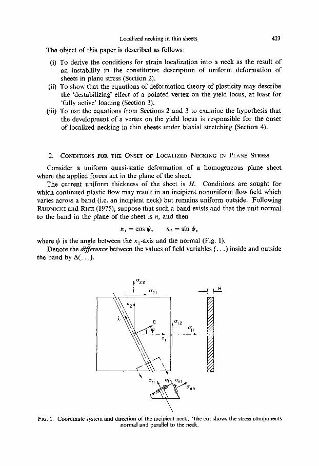
The current uniform thickness of the sheet is H. Conditions are sought for which continued plastic flow may result in an incipient nonuniform flow field which varies across a band (i.e. an incipient neck) but remains uniform outside. Following RIJDNICKI and RICE (1975), suppose that such a band exists and that the unit normal to the band in the plane of the sheet is n, and then
n, = cos I//, n2 = sin J/,
where $ is the angle between the x,-axis and the normal (Fig. 1). Denote the dQ.%rence between the values of field variables (. . .) inside and outside
the band by A(. . .).
FIG. 1. Coordinate system and direction of the incipient neck. The cut shows the stress components normal and parallel to the neck.

424 S. ST~REN and J. R. RICE
Since the flow field is restricted to vary across the band, the difference in velocity is
Avz = rz, insidcvL’a, outside =.fbL(xI cos $+x, sin $) =_fU(nsxa). (1)
where AvU (U = 1, 2) are the components in the plane of the sheet and c’,, ou,side is the linear continuation of the outside velocity field through the band.
The difference in rate of deformation is thus
A(~v,/~x,) = 07(Av,)/(?x,~ =f,‘(n;,x,,)np = ganP, (2) where
9, =_C(nflxp) (x, B, 1’ = 1, 2).
A further restriction on the incipient non-uniform flow field is that stress equilibrium continues to be satisfied.
The equations of equilibrium in the plane of the sheet are, for the stress resultants
Ho,,, a(Ha,p)/ax, = 0 (a, /I = 1, 2) (3)
(HILL, 1950, p. 300), and for the rate of change of the stress-resultants at a fixed point in space
L- (a/ax,)[a(Ha,,)jat] = @/r?X,){(HQJ - L$d(HQ)/(l?X,.]) = 0, (4)
where (?) denotes the instantaneous material derivative, and ax0 (n, ,G = 1, 2) are the true stress components in the plane of the sheet (ci3 = 0, i = 1, 2, 3). From the assumptions of uniform deformations and homogeneous material, it follows that (3) is identically satisfed everywhere and (4) reduces to
(W,)(A8-,, + o,~ AD,3 1 = 0, (5)
where Ac?=~ is the difference in stress-rate corresponding to the incipient flow field given by (2), and
AD,, = A.ljlH (6)
is the difference in thickness-strain rate inside and outside the band. Since AC?,, and AD,, correspond to the flow field given by (1) and (2) they
only vary across the band and vanish outside. Thus, equation (5) yields
n,A6,8+n,a,,,rAD,, = const. = 0. (7)
In order to relate the Ac?~~ and AD,, to the g,-functions, the constitutive equations must be specified. Assume for the time being that the following Zinear rate-relations are valid :
caS = Lq?,,(~~,l~%), D,, = M,,(u’c,.dx), (8)
where the ‘moduli’ LnPya and M.,d are some functions of the current stress-state and the constitutive parameters such as elastic moduli, rate of work-hardening, etc. Equations (8) are usually derived from the general three-dimensional equations by requiring oi3 = 0 (i = 1, 2, 3), i.e. plane stress, and solving for D,; in terms of D,,].
If L&a and MY8 remain the same inside and outside the neck at the point of inception, then the following differences may be formed :
A6n, = Law WQx-,) = &.+a nag,, AD,, = M,,A(&,/&,) = M.,,n,g,, t
(9)
where (2) has been used.

Localized necking in thin sheets 425
By substitution of (9) into (7), we obtain the following linear homogeneous equations in g 1, gz :
(norL.Bydnd+n.~aSMydn,)g, = 0. (10)
The condition for the onset of necking is met if (10) is satisfied for some non-zero g1 and/or g2, that is, if
det (n,Laaydnd+n.a,BM,,n,) = 0.
Discussion of the validity of (9) will be given subsequently.
(11)
3. CONSTITUTIVE RELATIONS
In this section we discuss the equations of deformation theory of plasticity as a model for flow-theory behavior under fully-active stress-increments at a yield vertex. We consider finite deformations of a rigid-plastic incompressible material.
3.1 Equations of deformation theory of plasticity
By assuming the Mises yield condition and material isotropy, the small-strain deformation theory (HILL, 1950, p. 45) is modified to the following relation between total plastic deformation-measure sij and some rotation-invariant stress-measure ~ij:
Eij = n7~j = ~(Tij-47kkSij). (12)
Many definitions of ei, are possible. When the material deforms such that the principal directions of Eij are fixed in the material, however, we require that the defined Eij gives the logarithmic or ‘natural’ strain. This is the strain-measure commonly used in the sheet-forming literature (KEELER and BACKOFEN, 1963) and is shown on Fig. 2. Some possible definitions which satisfy this requirement are discussed in
+I”(%) G,‘d”($) q= A($) FIG. 2. A sheet before and after non-rotational, uniform plastic defomlation.

426 S. ST~REN and J. R. RICE
Appendix I. AS stress measure zij it is convenient to choose the symmetric stress- tensor which is conjugate to cij, that is
zijgji = rate of stress-work per unit reference volume (13)
where 8ij = d&ij/dt (HILL, 1968).
By squaring and adding the equations (12) we obtain
where
-2 Y = 41222
y2 = 2s..&.. 1J Jl
and -2 7 = +r;jZ;j
are the equivalent strain and stress respectively. rij components. From (14), the scalar /1 is given by
1 = 1/2h, = q/2?,
(14)
(15)
(16)
is the deviatoric part of the stress
(17)
where h, = ?/v is the secant modulus on the stress-strain curve (Fig. 3).
FIG. 3. Stress-strain diagram showing tangent modulus h and secant modulus hl. N denotes the work-hardening index.
The rate-form of (12) is found by taking the time-rate on both sides of it, i.e.
iij = XZij + Mij,
where x = (z’/2T)(dv/dT-y/?) = (2’/2?)( l/h - lihl) (18)
and h = dz/dr (19)
is the tangent modulus on the stress-strain curve (Fig. 3). We thus have
2gij = (l/h,)2ij+(l/h- l/hl)(zfj~;,/2T’)z,,. (20)
If we choose Eij to be the ‘spinless’ deformation as defined in Appendix I, then (20) yields
where (21)
(22)

Localized necking in thin sheets 427
is the Jaumann rate of the true stress gij, and
Dij = 3(aUi/dXj + avj/aXi), Szij = t(aoi/aXj-aUj/aXi) (23)
are the instantaneous rate of deformation and the spin tensor respectively. The Jaumann rate of the true stress is the stress-rate observed if the observer
follows a system of reference that rotates with the spin tensor Qij of the particle. If the material work-hardens according to the power-law, i.e.
7 = ~l(r/rY, (24) then
h = d?/dr = N(z,/y)(y/y,)N = N(?/y) = N/I,
and (21) can be written
(25)
2hlDij = Zij+((l -N)/N)(o:ja;,/2z2)~,,. (26)
3.2 The equations of deformation theory as a model for a vertex on the yield 10~14s
According to the flow theory of plasticity, the plastic strain rates for an isotropic material, with Mises smooth yield-locus, are given by
205 = (l/h)(aljo;,/222)~,, if ~J;~Z,~ > 0,
0 if c&Z,, I 0, (27)
which can easily be given geometrical interpretation by observing that
Vii,. = ~~jIJ2? (mijmij = 1, mkk = 0)
are the components of the unit normal m to the yield locus in stress space (Fig. 4(a)). As a consequence of normality, the strain-rate vector Dp is always directed
parallel to m even if the stress-rate vector g’ has a component normal to m.t This restriction on the strain-rate stabilizes the flow, since sudden changes in the stress-rate do not change the flow pattern instantaneously.
Suppose now that we relax this restriction by allowing the component of the stress vector normal to m, where there are only small deviations from the direction m, to contribute to the plastic strain rate by (RUDNICKI and RICE, 1975)
D$ = (1/2h,)(g’- m(m : g))
where h, is the rate of work-hardening in that direction. Summing up the two contributions (Fig. 4(b)) we obtain
DP = Dp+D$ = (1/2h)m(m : :)+1/2h,(?-m(m : g))
or
and the rate-form of the equations of deformation theory are recovered, if h, is identified as the secant modulus. (Compare with (21).)
Now, consider a yield locus with a pointed vertex at the current stress-state. Guided by the model of multi-slip in a polycrystal, the vertex is imagined as the intersection of many smooth yield-surfaces (KOITER, 1953), and the plastic strain
t This component is given by 2 - m(m : z).
428 S. ST~REN and J. R. RICE
4
YIELD LOCUS
-YIELD LOCUS
YIELD LOCUS #’
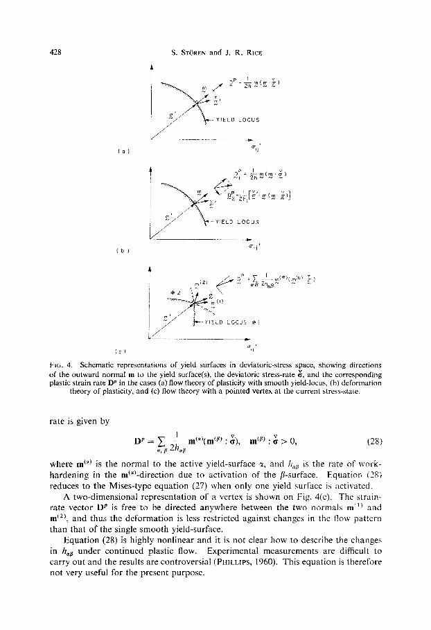
Ftc. 4. Schematic representations of yield surfaces in deviatoric-stress space, showing directions of the outward normal m to the yield surface(s), the deviatoric stress-rate & and the corresponding plastic strain rate D’ in the cases (a) flow theory of plasticity with smooth yield-locus, (b) deformation
theory of plasticity, and (c) flow theory with a pointed vertex at the current stress-state.
rate is given by
DP = c l’~_ m(‘+(m(~) : ;;), a, IJ 2b
mcP) : g > 0, (28)
where rnca) is the normal to the active yield-surface x, and II,, is the rate of work- hardening in the m ‘“‘-direction due to activation of the p-surface. Equation (28) reduces to the Mises-type equation (27) when only one yield surface is activated.
A two-dimensional representation of a vertex is shown on Fig. 4(c). The strain- rate vector DP is free to be directed anywhere between the two normals m” ’ and m(‘), and thus the deformation is less restricted against changes in the how pattern than that of the single smooth yield-surface.
Equation (28) is highly nonlinear and it is not clear how to describe the changes in h,, under continued plastic flow. Experimental measurements are difficult to carry out and the results are controversial (PHILLIPS, 1960). This equation is therefore not very useful for the present purpose.

Localized necking in thin sheets 429
HUTCHINSON’S (1970) calculations for a particular strain-path and small plastic strains have shown that for small changes in the directions of & the polycrystalline, multi-slip model predicts plastic moduli close to those given by (17).
Guided by this result and the need for a simple description of the destabilizing effect of a vertex (RUDNICKI and RICE, 1973, the following conjecture is made: Irl the case of continued plastic JEow with small deviations from proportional loading, so that all the yield surfaces which intersect at the vertex are activated (‘fully-active loading’), the rate-form of the equations of deformation theory (equation (21)) can be used as a model of a pointed vertex. This is consistent with a limited path-independence of E on all routes to the current z that are everywhere ‘fully active’.
4. ANALYSIS AND NUMERICAL RESULTS
In plane stress (i.e. ~i3 = 0) equation (26) reduces to
2D,, = ; {&r + ((1 - N)/N)(&/~%;s :,a)> (a, B = 1, 3, (29)
033 =-(D,,+D,A where
and ? = 3(a:1-~11a,,+o:,>+o:, = &J&$q.
From equation (29),
which, when substituted into (29), yields
:Ls = 2 ; {D,@ -(I - N)(o~~/~~~)(o,,D,,)},
and since Cl1 = 2a;,+o;,, o22 = 2o;2+o;l,
we obtain the inverted form of (29):
P cl1 =2~{(2-(1-N)&/2?2)D,,+(1-(1-N)~,,a22/2~2)D22
-(I-N)(o,, ~12/27~)2&2),
h gz2 = 2 - ((1 -(l-N)
N a11az2/252)D11+(2-(1-N)o~,/212)D2,
-(I -N)(a220,2/212)2D,2),
S 12 = 2; {-(1--N)(~,,~,2/2~2)D,,-(1-~)(~22~,2/2~Z)D22
+(-r-(1 --N)62P2P&2},
D33 =-(D,,+D22>,
(30)
(31)

430 S. ST~REN and J. R. RICE
where, according to (22) with ci3 = 0,
:rl = ir,, +2cr,,R,,,
$2 = fi22+2~2tQI*, (32)
012 = &12+-a, 1%2+~22%1, i aI2 = ~(~u,/ax,--i?u2/ax,) = -a,,,
D,, = _:(av,jax, $ &@x,) (x, /I = 1,2). (33)
By substituting (33), (32) into (30), (31), a particuiar form of the linear rate-relations (8) is obtained.
By assuming that the material outside the band continues to load plastically at the onset of necking, the differences given in (9) can be formed.
Without loss of generality we can align the reference axes x1, s1 (Fig. 1) along the directions of principal stresses, i.e.
6 II = @I, cJ.22 = fi2, (it2 - - 0.
Then, the condition for continued equilibrium (equation (7)) yields
nlA\ci,,+n2A&,, --)?I 0,(81 n, +92nz).= 0, n,A&,,+n,Ad-,2 -‘12LT&1n, +gzn;) = 0, 1
(34)
and the difference between the fields inside and outside the incipient neck (equa- tions (9), (30), (31) and (32)) is
A; , , = A&I1 = 2:: {(2-(1 -N)a:/2?2)g, ?I1 +(I -( 1 -N)a,o,/2i.2)g2/~2j,
A&, = ASZ2 = 2,;; {[l-(1 -N)cr,cizi2f)gIn,t(2-(1--)oI/2zZ)g,n,~, (35)
A: 1:! = A~,,-$(a,-a,)(g,tl,-(j,,i,) =;(gInZ+gZnJ.
By substituting (35) into (34) we obtain the following linear homogeneous equations
where
(r = $(a, +cr,), Z = +(cTi -fJ2)
and the relation
?I:$-12: = i
has been used. Non-zero functions g , , g2 can be found if the determinant of the coefficient-matrix

Localized necking in thin sheets 431
vanishes. By using this condition and after some algebraic manipulations, we obtain
’ [4-((1 -N)/12){(aln:+a,n2)2+4(a,-a,)2n:nl}]
- CJ; n: + a; nz”)/? + ((1 - N)/213)(q - cr,)(of n’: - c: ?$)I
- 9(u1- a2)(a1 n: - u2 n;yz2 = 0. (
By observing that
Cl n: +02 nf = a,,, a; n: + a; n; = CT;,,
-3(01 -o&al n: - 02 n;) = f2 - a;, CT,
3Y2 = o:-fs 1 c’z + 0; = 0;” - on” oft + 0; + 3a;t,
(37) can be written
($)2 {[4W+(l -N)3&]/?} - ({&) ([3f#+(l -N)(+-o;,o)a,“]/z)
37)
-(2”-f+)/? = 0, (38)
where c”,,, ant, (T,, are the stress components parallel and normal to the incipient neck (Fig. 1).
If (37) can be satisfied for some h > 0, then the condition for incipient neck formation in a power-law work-hardening material is met. Since h (and h, = h/N) is a uniformly decreasing function of the equivalent plastic strain 7, the maximum value of h which satisfies (37) gives the condition when the onset of necking is first possible.
By solving (37) with respect to h and finding the angle $ which optimizes h, we have solved the problem. This is not easy to do analytically, since it has not been possible to find simple expressions for the roots (eigenvalues) of the equation. It seems that a numerical procedure is necessary.
Now, before doing this it may be useful to study the experimental observations on sheet-metal ductility as reported by KEELER and BACKOFEN (1963), AZRIN and BACKOFEN (1970), GHOSH and HECKER (1974), and HECKER (1975). In their experi- ments, principal strains are imposed on the sheet in an approximately constant ratio
p=& ./e m,n max = El/E, = de2/del, (39) where &a are the logarithmic strains defined on Fig. 2. For an isotropic material, following the Mises yield condition, this means a stress ratio
a = aJa1 = (1+2p)/(2+p). (40) By carefully measuring the increments of principal strains on a grid deforming with the sheet, they were able to locate approximately the strain ET at which localized necking started. By varying the imposed strain-ratio p, a so-called ‘forming limit’ curve
ET = F(P) could be found.
By assuming an isotropic, power-law work-hardening material, it is observed that
or h, = ?/jj = aJ[2&,(2+p)]
ET = (a,NIC2(2 + ~Pcrl, (41)

432 S. ST~REN and J. R. RICE
where h,, is the maximum rate of work-hardening at possible. The limit-curve predicted by HILL (1952) for a isotropic, rigid-plastic, Mises material is
8; = N
I +p (- 1 < p I O),
which localized necking is power-law work-hardening,
(42)
where the angle $ between the maximuni principal strain direction and the normal
n is given by
$ = arctan (,I -p), \ or
11: = I Z -P ~~~ 1
(43)
I -p’ 1’2 = 1 -@I
This solution does not allow localized necking for biaxial stretching. i.e. p > 0. The angle $ = arctan (j-p) corresponds to the direction of zero extension along the neck, i.e. vanishing deviatoric normal stress in that direction (equation (27)),
fl;, = 0.
In the region where p > 0 and where no direction of zero extension exists in the plane of the sheet, it is observed that the neck forms normal to the largest principal strain, i.e. $ = 0, n, = 0. This is the neck orientation which corresponds to minimum
extension along the neck and where also a;, = a; has a minimum. Led by these observations and by the numerical solution of (37) in Appendix II,
we give analytical solutions for ET in two particular cases, as follows.
(i) a;, = 0, corresponding to :ero extension along the neck
The following solution .si, min is then found :
ET = [N/(1 +p)]{(l -N)/2+[(1 +N>2/4-pN/(l +p)2])}-1,
$=arctan(J-p) (-1 <p(O). 1 (44)
(ii) o;, = a;, corresponding to minimum extension along the neck
The solution which then gives C, minimum is (it can also be obtained directly
from (36))
F: = [3p’+N(2+p)‘]/[2(2+p)(l +p+-$)I,\
lj=o (-1 Ipl I). J (45)
The ‘forming limit’-curves for different values of the hardening-index N as predicted by (37) (see Appendix 11) are shown on Fig. 5.
For p 2 0 (Q 2 0) the curves agree precisely with (45), that is, the predicted neck forms along the direction of minimum principal strain. ‘Forming limit’- curves, found experimentally in plane biaxial stretching by AZRIN and BACK~FEN (1970) and GHOW and HECKER (1974) for different materials are also shown on Fig. 5.
It should be observed that these materials (except for A-K steel) do not follow the power-law work-hardening (24) very well, and the index n’ used on the Figure corresponds to
11’ = d(ln a)/cl(ln E) = (dc?jclF)/(a/c) = lljlr , = N
at the onset of tech-ing in pure tension. This means that the value /l/11, may vary with p and E’;, so that the limit-curves found experimentally need not to be curves

Localized necking in thin sheets 433
[u] Arrin S Backofen (1970)
[b] Ghosh 8 Hecker (1974)
[c] Ghosh (19741
o A-K steel (N=0.24) [c]
x Brass 70/30 (n’=0.47) [c]
‘Aluminium l/4 hard (n’=O.04) [c]
Ean\\
less steel (n’=0.55)[al
Brass (n’=0.47) [b] A=K steel (N=0.21) [b]
Aluminium (n = 0.04 1 [ b]
1 1 I I I I I I I I I I I I - -.8 -.7 -.6 -5 -.4 -.3 -.2 -.I 0 .I .2 .3 .4 .5 .6 .+
‘2
FIG. 5. Predicted and observed ‘forming limit’curves. The fully-drawn curves are the results from the numerical calculations (Appendix II). For 0 < p I 1, they agree precisely with equation (45). For -1 I p I 0, the results are compared with Hill’s prediction, equation (42), and the prediction of equation (44). Experimentally-observed limit-strains for different materials from different sources are shown. The n’-numbers correspond to N in uniaxial tension at the point of instability
for materials which do not closely obey power-law work-hardening.
of constant N. It further should be remarked that the materials tested are not isotropic. The normal anisotropy-index R varies between 1.54 (A-K steel) and
0.76 (aluminum). For p < 0 (Q < 0), the Hill solution (42) and the present solution for neck
inception along the direction of zero extension (equation (44)) are also shown. The numerically-found directions of neck inceptions for different N-values are shown on Fig. 6 and compared with the direction of zero extension. When -0.2 < p 2 0 or N 4 1 the predicted directions are very close to the zero-extension direction.
Some data from pure tension tests (GHOSH and HECKER, 1964) are also plotted on Fig. 5. For brass with IZ’ = 0.47 and R = 0.9, the present prediction seems to be favored; but for the other materials the results are more inconclusive.
4.1 Neck perpendicular to the major principal stress
Finally, it may be remarked that, when it is assumed apriori that the neck forms perpendicular to u1 (as observed in the experiments for p > 0), simple general expressions result for the necking condition. Using principal axes notation, the equilibrium requirement (7) becomes A61 +a, AD3 = 0 where, to meet the kine-

434 S. ST~REN and J. R. RICE
FIG. 6. The angle v between the direction for maximum principal strain and the normal to the direction of the incipient neck. The numerical rest&s for different values of N are compared with the direction of zero extension along the neck when p < 0. When p > 0, the predicted neck forms
at v = 0 for all values of N.
matical condition (2), AC?, and AD, are to be computed with AD, = 0. This can be re-interpreted as the condition for the nominal stress in the l-direction to be stationary with respect to variation of the imposed planar principal stretching rates in the l-direction only (i.e. AD, # 0, AD, = 0).
If one assumes incompressible deformation, so that AD, = -AD,, then the local necking condition is
crl = A&-,/AD,. (46)
This is not the same as the condition for attainment of a load maximum in the pre- bifurcation deformation (namely, g1 = Cl/D,), unless that pre-bifurcation state
corresponds to plane strain (D, = 0). Using the Rudnicki-Rice model of response at a yield vertex (equation (AI.4))
to compute A&,/AD,, the local necking condition given by (46) becomes
UI = [(2~2-~,)2111+3LT:h]i(OI-alaz+a:)
= [3p’h, +(2+p)2h]/(l +p+p2). (47)
In the latter version of the above formula, equation (40) is used, as would be appro- priate for proportional straining up to the necking point. For power-law work- hardening h is given by (AII.3) and using the deformation-theory model to choose
Localized necking in thin sheets 435
the vertex modulus h, as h/N, this reduces to the result given by (45). Alternatively, any experimentally determined work-hardening rule and choice for the vertex modulus can be inserted into (47) to obtain a more accurate prediction of necking conditions.
Equation (47) serves also as a basis to summarize, in a simple manner, the role of the yield vertex. For the rigid-plastic material with a smooth isotropically-expanding yield surface, h, = co and no local necking bifurcation can occur, except under plane-strain conditions (a, = 2a,, p = 0). Alternatively, the same constitutive law will apply for an incompressible elastic-plastic material with a smooth yield-surface, if h, is identified as the elastic shear modulus. Then, the predicted value of c1 at local necking is of the same order as the shear modulus, except at conditions near plane strain. By contrast, vertex models lead to a substantially smaller value of h,, typically only a few times h (e.g. h, = h/N for the model in the present paper). This results in proportionally smaller values of g, for local necking, and the results (reported in terms of &I in Fig. 5) seem to compare favorably with experimental measurements.
5. CONCLUSIONS
Due to the simplified constitutive model used in this investigation, there is no point in discussing details of the discrepancies between the predicted and the observed ‘forming limit’-curves presented in Fig. 5. Merely the existence and the trends of the prediction are sujkient to draw some important conclusions, stated as follows.
(i) The onset of localized necking in a sheet seems to be explainable as a bifur- cation from a state of uniform deformation, even when the pre-bifurcation defor- mations contain no direction of zero extension in the plane of the sheet. No assump- tions of abrupt changes in the stress-strain relation or of pre-existing macroscopic inhomogeneities seem to be necessary. Still, it is clear that suitable initial imperfec- tions will aid the development of a neck, and certainly when the problem is analyzed on the basis of the rigid-plastic isotropic-hardening material model, with a smooth yield-locus at the applied stress-point, no neck can be predicted for p > 0 without the assumption of imperfections (MARCINIAK and KUCZYNSKI, 1967). Both initial imperfections and the kind of constitutive features discussed here, allowing bifurcation instability, may contribute in general, although a tentative interpretation of the com- parison with experimental results is that it may be unnecessary to invoke the former.
(ii) This kind of instability is very sensitive to details in the stress-strain relations of the material. The destabilizing effect of a pointed vertex on the yield locus in a rigid-plastic incompressible material is demonstrated in the present paper. Other effects, such as anisotropy (BERT and SHAH, 1971), non-normality (RUDNICKI and RICE, 1975), elasticity (HUTCHINSON and MILES, 1974), and pre-fracture plastic dilatation (BERG, 1970), could possibly contribute and might also be considered.
(iii) More generally, it can be argued that the Prandtl-Reuss model of isotropic expansion of a smooth yield-surface is clearly too simple a description of the change in properties during plastic flow. In many circumstances this is inconsequential, but for problems of the type considered here, involving bifurcations, further efforts should be directed towards a more detailed description of work-hardening in solids, particularly with regard to clarifying the nature of the relation between stress incre- ments and strain increments over a wide range of directions for the latter.
29

436 S. ST&EN and J. R. RICE
ACKNOWLEDGMENT
This work was supported by the ARPA/NSF Materials Research Laboratory at Brown University and (additionally, for S. S.) by the Royal Norwegian Council for Scientific and Industrial Research (NTNF). The writers are grateful to Professor A. Needleman (Division of Engineering, Brown University) for helpful discussions.
REFERENCES
AZRIN, M. and BACKOFEN, W. A. 1970 BATDORF, S. B. 1949 BATDORF, S. B. and 1954
BUDIANSKY, B. BERG, C. A. 1970
BERT, C. W. and SHAH, J. J. 1971
BUDJANSKY, B. 1959 GHOSH, A. K. and HECKER, S. S. 1974 HECKER. S. S. 1975
HILL, R. 1950
HUTCHINSON, J. W. HUTCHINSON, J. W. and
MILES, J. P. KEELER, S. P. and
BACKOFEN, W. A. KOITER, W. T. MARCINIAK, Z. and
KUCZYNSK& K. PHILLIPS, A.
RICE, J. R.
1952 1958 1962 1967 1968 1970 1974
1963 Trans. Amer. Sot. Metals 56, 25.
1953 Quart. appi. Math. 11, 350. 1967 ht. J. Mech. Sci. 9, 609.
1960
1973
RUDNICKI, J. W. and RICE, J. R. 1975
Met. Trans. 1, 2857. J. Aeronaut. Sci. 16, 405. J. appl. Mech. 21, 323.
Inelastic Behavior of‘ Solids (edited by KANNINEN, M. F., ADLER, W. F., ROSEN- FIELD, A. R. and JAFFEE, R. I.). p. 171. McGraw-Hill, New York.
Deveiopments in Mechanics, Vol. 6 (Proceed- ings of the 12th Midwestern Mechanics Conference. (edited by LEE, L. H. N. and SZEWCZYK, A. A.), p. 531. University of Notre Dame Press, Notre Dame, JN., U.S.A.
J. appl. Mech. 26, 259. Met. Trans. 5, 2161. Trans. A.S.M.E. 97, Series H, J. Eng. Mut.
Tech. 66. The Mathematical Theory of Plasticity. Oxford
University Press. J. Mech. Phys. Solids 1, 19. Ibid. 6, 236. Ibid. 10, 1. Ibid. 15, 79. Ibid. 16, 229, 315. Proc. Roy. Sot. Lond. A319, 247. J. Mech. Phys. Solids 22, 61.
Plasticity (Proceedings of the Second Sympo- sium on Naval Structural Mechanics. Brown University. April 1960), (edited by LEE, E. H. and SYMONDS, P. S.), p. 202. Pergamon Press, Oxford.
Plasticity and Soil Mechanics (Proceedings of the Symposium on the Role of Plasticity in Soil Mechanics. Cambridge. Septem- ber 1973), (edited by PALMER, A. C.), p. 263. Cambridge University Engineering Department, Cambridge, England.
J. Mech. Phys. Solids 23, 371.

Localized necking in thin sheets 437
SANDERS, J. L. 1955 Proceedings of the Second U.S. National Congress of Applied Mechanics (Univer- sity of Michigan, Ann Arbor. June 1954), (edited by NAGHDI, P. M.), p. 455. Ameri- can Society of Mechanical Engineers, New York.
&WELL, M. J. 1972 Stability (edited by LEIPHOLZ, H. H. E.), p. 85. Study No. 6, Solid Mechanics Division, University of Waterloo, Waterloo, Ontario, Canada.
1974 J. Mech. Phys. Solids 22, 469. SOWERBY, R. and DUNCAN, J. L. 1971 ht. J. Mech. Sci. 13, 217.
APPENDIX I
AIternative formulations of deformation-theory models for yield surfaces with vertex at the current stress-point
Assume that the equations of deformation theory of plasticity in its simplest
isotropic form, E = (1/2h,)+, (AI.1)
and in their rate-form,
$, = (1/2/2,)?+((1/2h)-(1/2h,))(z’ : 212’ : T’)T’, (AI.2)
govern finite rigid-plastic deformation for a limited range of loading regimes that includes, but is not restricted to, proportional stress increase and fixed principal axes of E (BUDIANSKY, 1959).
We now look for rotation-invariant definitions of E and t that have the following
properties :
(i) E equals the logarithmic strain measure when the material deforms with principal axes that are fixed relative to the material (KEELER and BACKOFEN, 1963).
(ii) z is congugate to E (HILL, 1968). For incompressible materials this means
that the following equation has to be satisfied (equation (13)) :
z:E=o:D, (AI.3)
where (r is the true stress and D the instantaneous deformation-rate (equation (23,)). This requires that z = <r when the principal axes of stretching are fixed relative to
the material and to space.
The alternative formulations thus obtained are compared with the rate-equation proposed by RUDNICKI and RICE (1975) :
D = (1/2h,);‘+((1/2h)-(1/2h,))(o’ : +J’ : d)d, ; = k++Ta+aSL, (AI.4)
where R is the spin tensor (equation (23,)) and g the Jaumann rate of the true stress. For the sake of reference, some equations from the general analysis of defor-
mation are now written down. Let the Lagrangian description of the deformation process be represented by
dx(t) = F(t) dX, det (F(t)) > 0, (AI.5)

438 S. ST~REN and J. R. RICE
where X and x(t) denote the initial and current coordinates of material points. F(t) is the deformation gradient. According to the polar decomposition theorem,
F(t) = R(tjU(tj = RMAM“, (A1.6)
where U(t) = M(tjA(tjMT(tj = UT(t) is the pure deformation, A is the diagonal matrix of U, and M is the orthogonal matrix with the unit eigenvectors of U as columns, M-’ = MT, and R(t) is the rigid rotation, R- ’ = R’. det R = 1. det F = det U. If the material is incompressible, then
det U = I. (A1.7)
The logarithmic strain zL is defined by
zL = M In A MT = In U. (A1.8)
The Eulerian description of the process is given by
dv = elk = fi(t)F-‘(tj dx = (D-t-n) tix, k(O) = dX, (Ai.9)
where the instantaneous deformation-rate D is the symmetric part of I?F-’ and the spin tensor R is its antisymmetric part. By using (AI.5), D and R may be written as
D = +R(iTV1 +U-‘iljR=
= RM[liA-1 ++(AtiTMA-’ +A-‘M=l+lA)]M=R, (AI.10)
n = B~~+~~(ti~-*-u-~tijR~
= fiRT+RMIMTI\;I+_S(ARiITMA-‘-A-‘M=1\SIAj]M’R. (AI.1 1)
In view of these general equations and the imposed restrictions (ij and (ii) above, the following definitions (a), (bj, (cj of E are proposed.
(a) The ‘rotationless’ deformation Ed
The most natural choice of E is perhaps
ER=)j(ijU-l+U-liljd,, 0
where the integrand
(AI. 12)
k, =+(iJU-‘+U-‘ir) = R=DR (A1.13)
is the ‘rotationless’ part of the instantaneous deformation-rate D (equation (AI.10)). (ij When I$l = 0, i.e. fixed directions of principal axes of Ed, then
1, = MAA- ‘MT, E~=M [~~A-‘dtlMT=MlnAMT,
that is, it gives the logarithmic strain, equation (AI.8). (ii) From (AI.3),
zR : & = zR : (R=DR) = (RzR=) : D = c : D,
and we obtain the conjugate stress
t R = RTaR. (Al.14)
(iii) The time-rate of zR is
i, = R=(& + Rk=a + alkRTjR. (AI.151
Substitution of (AI.13)-(AI. 15) into (AI.2) then gives
R=DR = (1/2h,)R=(~+R~=~+alkR=)R+((1/2h)-(1/217~))(~;( : i, (rk : G)R’a’R

or
Localized necking in thin sheets 439
D = (1/2h,)&+((1/2h)-(1/2h,))(a’: i/a’ : a’)~‘, (AI.16) where
: = ++RR=o+aRR’. (AI.17)
Equation (AI.16) is the rate equation proposed by RUDNICKI and RICE (1975) but with the Jaumann stress-rate (equation (AI.4)) replaced by the rate given in (AI.17). It is observed from (AI.1 1) that these two rates coincide when A = I or when M = 0.
It should be noted that the integrand (AI.13) is not a total differential. This means that the aR is path-dependent and therefore does not possess the property of a strain- measure required by HILL (1968). Ed may thus be called a deformation-measure and not a strain-measure.
(b) The ‘spinless’ deformation Q
Another ‘candidate’ is the ‘spinless’ deformation
Q = 3 6 R*(t)(UU-’ + U- ‘U)R*T(t) dt (AI.18)
with the integrand
ts = 3R*(t)(UU-’ +U- ‘U)R*=(t) = R*RTDRR*T, (AI.19)
where R*(t) is a rotation chosen so that the deformation gradient F* = R*U is spinless, that is, from (AI.1 l),
(AI.20)
(AI.21)
or
$-&* = R*[R*=~*+t(OU-‘-U-‘O)IR*T = 0
R*%* = -+(UU-’ -U- ‘U) = R=(RR=-R)R.
(i) When &I = 0, then R* = I and as = In U. (ii) From (AI.3) and (AI.19),
zs : Gs = (RR*=rsR*RT) : D = (r : D,
and the conjugate stress is obtained,
zs = R*R=oRR*=.
(iii) By taking the time-rate of zs and making use of (AI.20), we have
zs = ; [R*RToR~*7 = R*RT;RR*T, (AI.22)
where g is the Jaumann rate (equation (AI.4)). Substitution of (AI.19), (AI.21), (AI.22) into the rate equation (AI.2) yields
R*R’DRR*= = (1/2hl)R*R=~fRR*T+((1/2h)-(1/2h,))(a’ : i?/tf : a’)R*R=a’RR**
or D = (1/2/&‘+((1/2h)-(1/2h,))(a’ : &f : d)d, (AI.23)
which is precisely the equation proposed by RUDNICKI and RICE (1975) as the rate equation of deformation theory.
aS is also a deformation measure, and not a true strain-measure, since ts is not a total differential.

440 S. ST~REN and J. R. RICE
Alternatively stated, both aR and Ed may be equated to an integral of the kind f Ddt computed for a deformation history that preserves the actual history of U, but that has appropriate spins superimposed upon it so that (i) for sR, I% = 0 and (ii) for Ed, R = 0 throughout the deformation. This is the origin of the names ‘rotationless’ and ‘spinless’, and the two rates 8 coincide exactly for infinitesimal strains (but arbitrarily large rotations) or for increments from special deformation- paths, such as those involving fixed principal directions relative to the material: these are cases for which R* = I.
(c) The ~o~a~~lhrnic strain zL
The logarithmic strain as defined by (AI.8),
eL = In U = M In A MT, (AI.24)
may also serve our purpose. It has the advantage of being a true strain-measure (HILL, 1968). The time-rate of cL is
2, = M~A-‘M~+~ In AMTtM In A&I’. (Al.25)
By comparing (A1.25) with (AJ.IO), however, it is observed that the general relation between kL and D is very complicated. In view of (AI.3), this implies that the expressions for the conjugate stress and its time-rate also become very complicated, and thus makes the strain-measure aL essentially intractable as a general measure in deformation-theory formulations.
From the above considerations we may conclude that both the ‘rotationless’ and the ‘spinless’ deformation measures may be used in formulating a theory that is at least tractable, but that the ‘spinless’ deformation Ed is to be preferred on these grounds since it gives a simple relation between the conjugate stress-rate and the Jaumann rate of the true stress. Of course, our tacit assumption is that there are no compelling physical grounds for preferring one of the above three measures as constituting the more fundamental measure for use in a constitutive law of the form (AI.]). In view of their common features as enumerated at the outset of this appendix, all are expected to give rather similar predictions, and our choice of Ed
is made on the basis of tractability and simpficity.
APPENDIX I I
Assume that the principal plastic strains E, and a2 in the plane of the sheet uniquely characterize the state of the sheet metal at the onset of necking. Denote the ratio between them by (equation (39))
p = E&I.
If the material is isotropic and the sheet is in a plane-stress condition, then. from (20) or (27),
1+2p

Localized necking in thin sheets 441
and the equivalent strain and stress may be written
7 = 2(E:+E1E2+E:)+ = 2s,(1+p+p2)$ (AII. 1)
f = (*(a:-a,o,+a;))+ = -+l+p+p2)f. 2+P
(AII.2)
Thus, the rate of work-hardening h for a power-law work-hardening material is given by
h = NT/r = Ncr1/2s,(2+p). (AII.3)
With substitution of (ATT.2) and (AII.3) into (37) and use of the relation
n; = l-n& (AII.4) we obtain
where F,(P, n,2, JW/~~-~~(P, $3 NWEJ-F~P, & N) = 0, (AILS)
F1 = 4N(l+p+p2)+3(1-N)(p+(1-p)n:)2,
F, = 6(1+p+p2)(p+(1-p)?z~)+(l-N)(2+p-(1-p)n:)(2+p-3(1+p)n:)(l-p),
F, = 2(1-p)(l+p+p2)(2+p-3(1+p)n;).
Within the actual range of the parameters, namely
-llPll, 0 I nf I 1, O<N<l,
it can be shown that the roots of (AII.5) are real (FZ+4F, F, 2 0) and at least one of the roots is positive (FJF, > 0 or FJFl I 0, F,/F, > 0).
For each incremental step of p, the algebraically largest value of I/L-~, within the range of ng and with N constant, is determined numerically. The inverse of this value, sf, is then the ‘limit-strain’. The result of this computation is plotted in Figs. 5 and 6 for different values of A?