Embed Size (px)
Citation preview

N A S A TECHNICAL NOTE - NASA 0-6721 ( 2 . 1
=-I
LOAN COPY: AFWL (
KIRTLAND
RETUR
AFB, N, DOUL)
APOLLO EXPERIENCE REPORT - WINDOW CONTAMINATION
by L. J. Leger dnd R. W. Bricker
Mdnned Spucecrczft Center H o ~ s t o n , Texm 77058
NATIONAL AERONAUTICS AND SPACE ADMINISTRATION WASHINGTON, D. C. -.. :..,.MkRCH' ,". 1972
https://ntrs.nasa.gov/search.jsp?R=19720012257 2019-02-03T18:46:31+00:00Z

TECH LIBRARY KAFB, NM
1. Report No. 2. Government Accession No. NASA TN D-6721
3. Recipient's Catalog No.
- _ ~ _ ~ ~~ ~ ~~
4. Title and Subtitle I 5. Report Date
APOLL.0 EXPERIENCE REPORT WINDOW CONTAMINATION F- 6. Performing Organization Code
7. Author(s) ~~~ . ~~
8. Performing Organization Report No.
L. J. Leger and R. W. Bricker, MSC 10. Work Unit No.
~ . ~ ~
MSC 5-284
9. Performing Organization Name and Address 914-13-20-21-72 Manned Spacecraft Center Houston, Texas 77058
11. Contract or Grant No.
~~ " . . . . 13. Type of Report and Period Covared 2. Sponsoring Agency Name and Address
National Aeronautics and Space Administration Washington, D. C. 20546
I Technical Note I 14. Sponsoring Agency Code
I ~~~~~ ~ _____
5. Suoolementarv Notes
The MSC Director waived the use of the International System of Units (SI) for this Apollo Experience Report, because, in his judgment, use of SI Units would impair the usefulness of the report or result in excessive cost.
6. Abstract
The problem of window contamination in the Apollo command module is reviewed. All five command module windows were contaminated while in earth orbit on the first three manned Apollo flights. The contamination, sources were identified and eliminated. Preflight testing of lunar module windows showed that no serious contamination should occur, and this conclu- sion was verified in subsequent manned flights. In this report, the command module window designs and materials are described, the window-contamination sources are identified, and the inflight and chemical analyses of the contamination are outlined. The corrective actions that were taken are reviewed. For the lunar module, the window design and materials and the preflight and flight evaluations are described. Window-design recommendations a re made.
7. Key Words (Suggested by Author(s1 1
' Spacecraft Windows ' Window Contamination ' Contamination
18. Distribution Statement
I
19. Security Classif. (of this report) ~~ ~
20. Security Classif. (of this page) 22. Rice' 21. NO. of Pages
None $3 00 17 None "~ .
For sale by the National Technical Information Service, Springfield, Virginia 22151

APOLLO EXPERIENCE REPORT
WINDOW CONTAMINATION By L. J. Leger and R. W. Bricker
Manned Spacecraft Center
SUMMARY
All five command module windows on each of the first three manned Apollo flights were contaminated while the spacecraft was in earth orbit. This contamination accu- mulated most often on the inner surface of the outer pane and on the outer surface of the middle pane of the three-pane window. By means of astronaut debriefing and post- flight examination of the recovered command module, three main sources of contamina- tion were identified: escape-tower-engine plumes, expulsion of waste water, and outgassing of elastomeric sealants.
Because contamination on the middle pane was a serious problem, a concentrated effort was made to eliminate the source of this contamination. The contamination was identified, by means of chemical analysis, as a silicone oil that resulted from outgas- sing of elastomeric window materials. By means of weight-loss experiments on these materials? it was demonstrated that a solution to the problem would be a 48-hour vacu- um bake of all appropriate sealants at 200" C before installation. Use of this technique reduced window contamination to an acceptable level.
As a result of the problems encountered with the Apollo command module win- dows, tests were conducted on a lunar module forward window before manned flight of a lunar module. The results of these tests indicated that no serious contamination would be encountered on the lunar module window. This conclusion was verified in subsequent manned flights.
INTRODUCTION
The first window used in the U. S. manned space flight program was on the Mer- cury spacecraft. In this case, only one window (consisting of four panes) was provided. Because of its size, the window provided only limited visibility, and it received only limited exposure to the space environment because of the relatively short flight dura- tions. Even for these conditions? window Contamination was noticed on some of the flights (refs. 1 and 2).
The Mercury window design influenced the Gemini and Apollo window designs. Major changes such as window size and number of assemblies were made; however,

the basic concept of a multipane assembly, wherein elastomeric sealants were used for a pressure seal, was retained. At the same time, other portions of the spacecraft underwent major redesign, but the resultant effects of these changes on the window assemblies were not considered. It is now known that these changes caused major problems in the maintenance of satisfactory windows in the Gemini and Apollo Programs. Window requirements became more stringent as space flights increased in complexity. Rather than simply providing a port for viewing and general photography, the windows became critical items in docking maneuvers, in scientific photography, and, eventually, in the lunar landings.
The first serious window-contamination problems were encountered in the early Gemini flights. It was determined by means of analysis that the majority of this con- tamination was a silicone oil that appeared on the outermost window surface as a highly viscous fluid. This contamination was produced by outgassing of the Gemini nose-cap heat shield. During launch, ascent heating of the spacecraft had caused the silicone oils in the ablator to vaporize and, subsequently, to redeposit on the cooler window surfaces. Also, very light deposits were located on the interior surfaces of the three panel windows, and the source of these deposits was identified as outgassing of window- sealant materials.
Because the contamination on the Gemini spacecraft windows was a clear oily fluid (during flight), it did not interfere severely with the functions of the spacecraft; therefore, immediate changes to the spacecraft were not considered necessary. Sev- e ra l window modifications were made for the later flights of the Gemini Program, however. One modification was a window cover for use during the ascent phase of flight; another modification was a vacuum bake for the window sealants in an effort to reduce the amount of outgassing (ref. 3). These changes reduced the contamination considerably; however, during the last Gemini flight, contamination could be detected on the windows.
Unfortunately, the analysis of the Gemini window-contamination results was not concluded early enough to be used in the Apollo Program, and contamination was a problem again on the command module (CM) windows. In an effort to provide clean windows for docking and other operations, the cause of this contamination was examined in detail. The physical characteristics of the contamination during flight were obtained through crew debriefings, and, in most cases, chemical analyses of the contamination could be made from samples collected postflight. From these data and from the out- gassing characteristics of the materials used in the window assemblies, it was possible to identify the major source of contamination: condensation of high-molecular-weight substances outgassed by sealant compounds. The results of the investigation that led to the identification of the contamination source as well as the approach that was taken to reduce the contamination are presented in this report. A similar program to evaluate the lunar module (LM) windows is reported also.
COMMAND MODULE WINDOWS
Window Design and Materials
Five multipane window assemblies are used on the Apollo CM. The standard win- dow designation used for the CM is shown in figure 1. Each assembly has three panes;
2

the two inner panes are part of the pressure-vessel structure, and the outer pane is part of the heat-shield structure. Cross-sectional views of these windows are shown in figures 2 to 4. The outer pane protects the inner panes during various phases of the
. mission, including entry of the spacecraft into the atmosphere. The rendezvous win- dows (numbered 2 and 4 in fig. l), as the name implies, were designed to provide a
' view of the LM during docking maneuvers. Most of the visual observations and photo- graphs were made using the other three windows because the surface area of these windows is larger.
Rendezvous wmdow Side window
Rendezvous window Hatch wlndow - 2
+ X
Af Hatch window Rendezvous wmdow
Rendezvous window
Side wmdow Side window
Figure 1. - Apollo CM window designation.
q K b l a t o r r o u t e r silica pane
,-Vacuum during orbit
\ Inner aluminosilicate panes
Figure 3. - Detail of CM rendezvous windows 2 and 4.
The panes of the window assemblies are constructed of two types of glass. Three different coatings are used in each assembly to improve the optical properties. The pressure-vessel panes are made of tempered aluminosilicate glass, and each surface (surfaces 3 to 6 in fig. 5) of the double-pane construction is coated with a proprietary,
Outer silica pane Vacuum during orbit
ner aluminosilicate panes
Figure 2. - Detail of CM side windows 1 and 5.
rAblator
aluminosilicate Danes L D r y Nz, 389 torr
during orbit
Figure 4. - Detail of CM hatch window 3.
3
I
antireflection agent. This coating increases @ M ~ F ~ coating
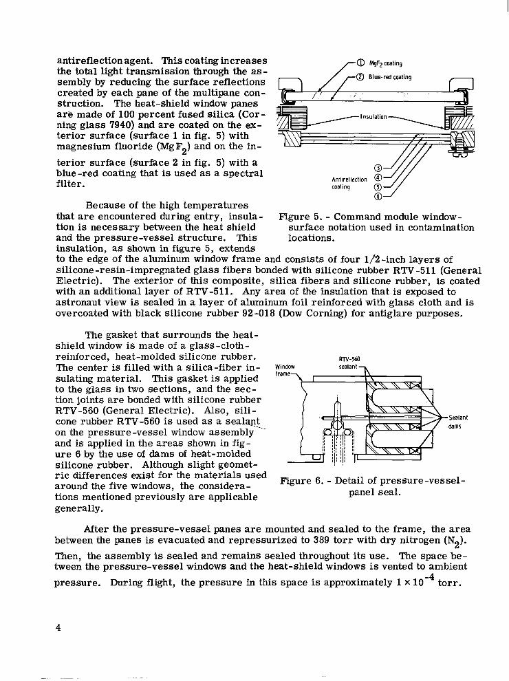
the total light transmission through the as- sembly by reducing the surface reflections created by each pane of the multipane con- struction. The heat-shield window panes are made of 100 percent fused silica (Cor- ning glass 7940) and are coated on the ex- -4 terior surface (surface 1 in fig. 5) with magnesium fluoride (MgF2) and on the in- terior surface (surface 2 in fig. 5) with a blue-red coating that is used as a spectral filter.
Insulation
Because of the high temperatures that are encountered during entry, insula- Figure 5. - Command module window- tion is necessary between the heat shield surface notation used in contamination and the pressure-vessel structure. This locations. insulation, as shown in figure 5, extends to the edge of the aluminum window frame and consists of four 1/2-inch layers of silicone-resin-impregnated glass fibers bonded with silicone rubber RTV-511 (General Electric). The exterior of this composite, silica fibers and silicone rubber, is coated with an additional layer of RTV-511. Any area of the insulation that is exposed to astronaut view is sealed in a layer of aluminum foil reinforced with glass cloth and is overcoated with black silicone rubber 92-018 (Dow Corning) for antiglare purposes.
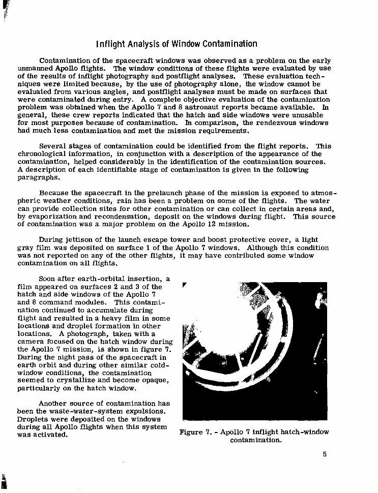
The gasket that surrounds the heat- shield window is made of a glass-cloth- reinforced, heat-molded silicone rubber. The center is filled with a silica-fiber in- sulating material. This gasket is applied to the glass in two sections, and the sec - tion joints are bonded with silicone rubber RTV-560 (General Electric). Also, sili- cone rubber RTV-560 is used as a seal* on the pressure-vessel window assembly and is applied in the areas shown in fig- u re 6 by the use of dams of heat-molded silicone rubber. Although slight geomet- ric differences exist for the materials used around the five windows, the considera- tions mentioned previously are applicable generally.
RN-560 Window
. .
-Sealant dams
Figure 6. - Detail of pressure-vessel- panel seal.
After the pressure-vessel panes are mounted and sealed to the frame, the area between the panes is evacuated and repressurized to 389 tor r with dry nitrogen (N2). Then, the assembly is sealed and remains sealed throughout its use. The space be- tween the pressure-vessel windows and the heat-shield windows is vented to ambient pressure. During flight, the pressure in this space is approximately 1 X 10 torr . -4
4
I nflight Analysis of Window Contamination
Contamination of the spacecraft windows was observed as a problem on the early unmanned Apollo flights. The window conditions of these flights were evaluated by use of the results of inflight photography and postflight analyses. These evaluation tech- niques were limited because, by the use of photography alone, the window cannot be evaluated from various angles, and postflight analyses must be made on surfaces that were contaminated during entry. A complete objective evaluation of the contamination problem was obtained when the: Apollo 7 and 8 astronaut reports became available. In general, these crew reports indicated that the hatch and side windows were unusable for most purposes because of contamination. In comparison, the rendezvous windows had much less contamination and met the mission requirements.
Several stages of contamination could be identified from the flight reports. This chronological information, in conjunction with a description of the appearance of the contamination, helped considerably in the identification of the contamination sources. A description of each identifiable stage of contamination is given in the following paragraphs.
Because the spacecraft in the prelaunch phase of the mission is exposed to atmos- pheric weather conditions, rain has been a problem on some of the flights. The water can provide collection sites for other contamination o r can collect in certain areas and, by evaporization and recondensation, deposit on the windows during flight. This source of contamination was a major problem on the Apollo 12 mission.
During jettison of the launch escape tower and boost protective cover, a light gray film was deposited on surface 1 of the Apollo 7 windows. Although this condition was not reported on any of the other flights, it may have contributed some window contamination on all flights.
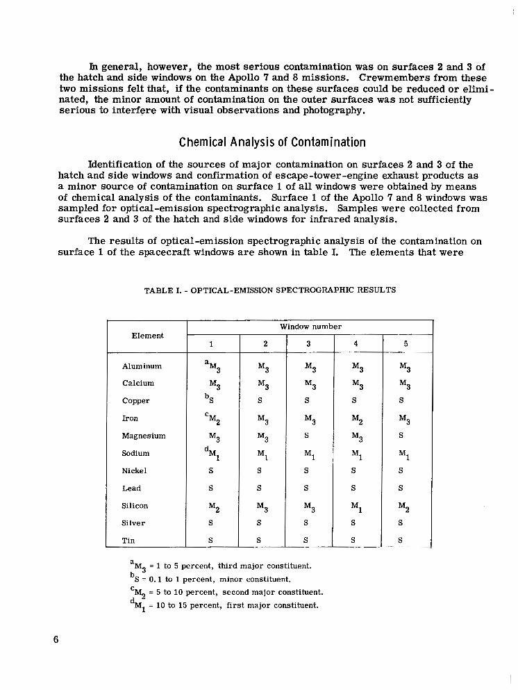
Soon after earth-orbital insertion, a film appeared on surfaces 2 and 3 of the hatch and side windows of the Apollo 7 and 8 command modules. This contami- nation continued to accumulate during flight and resulted in a heavy film in some locations and droplet formation in other locations. A photograph, taken with a camera focused on the hatch window during the Apollo 7 mission, is shown in figure 7. During the night pass of the spacecraft in earth orbit and during other similar cold- window conditions, the contamination seemed to crystallize and become opaque, particularly on the hatch window.
Another source of contamination has been the waste-water-system expulsions. Droplets were deposited on the windows during all Apollo flights when this system was activated. Figure 7. - Apollo 7 inflight hatch-window
contamination.
5
In general, however, the most serious contamination was on surfaces 2 and 3 of the hatch and side windows on the Apollo 7 and 8 missions. Crewmembers from these two missions felt that, if the contaminants on these surfaces could be reduced or elimi- nated, the minor amount of contamination on the outer surfaces was not sufficiently serious to interfere with visual observations and photography.
Chemical Analysis of Contamination
Identification of the sources of major contamination on surfaces 2 and 3 of the hatch and side windows and confirmation of escape-tower-engine exhaust products as a minor source of contamination on surface 1 of all windows were obtained by means of chemical analysis of the contaminants. Surface 1 of the Apollo 7 and 8 windows was sampled for optical-emission spectrographic analysis. Samples were collected from surfaces 2 and 3 of the hatch and side windows for infrared analysis.
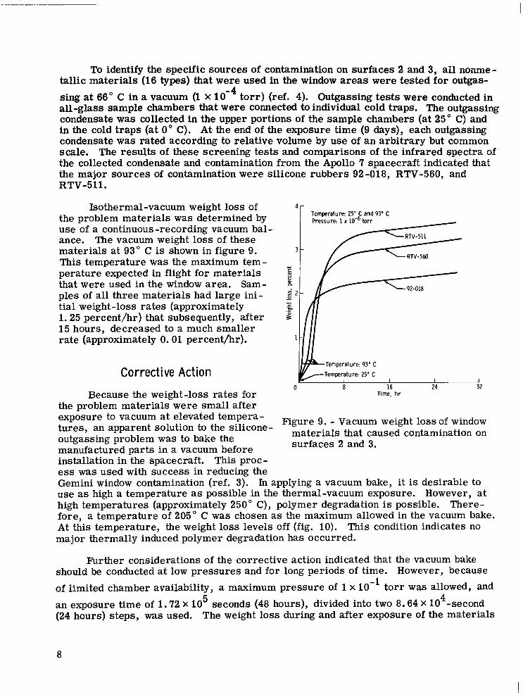
The results of optical-emission spectrographic analysis of the contamination on surface 1 of the spacecraft windows are shown in table I. The elements that were
TABLE I. - OPTICAL-EMISSION SPECTROGRAPHIC RESULTS
Element
Aluminum
Calcium
Copper
Iron
Magnesium
Sodium
Nickel
Lead
Silicon
Silver
Tin
1
a M3
M3 bS
M2
M3
C
dMl S
S
M2 S
S
2
M3
M3 S
M3
M3
M1 S
S
M3
S
S
Window number
3
M3
M3 S
M3 S
M1
S
S
M3 S
S
4
M3
M3
M2
M3
M1
S
S
S
M1 S
S
1 5
M3
M3 S
M3 S
M1 S
S
S
S
a
b~ = 0.1 to 1 percent, minor constituent. ‘M = 5 to 10 percent, second major constituent. dM = 10 to 15 percent, first major constituent.
M = 1 to 5 percent, third major constituent. 3
2 1
6

1; i present in large concentrations (such as calcium, magnesium, and sodium) are common ' to seawater, to which the window was exposed during recovery operations. Elements
(such as aluminum, iron, and lead) that were classed as the second and third major constituents of the contamination are not common to any source of Contamination that would result from recovery operations and special handling of the spacecraft. How- ever, these elements are common to the escape-tower-engine fuel. Therefore, this engine probably is a source of contamination.
Because of high entry temperatures and recovery conditions, no residue from the waste-water-dump system was expected to remain on the heat-shield windows. None of the elements found on the window by means of spectrographic analysis can be traced directly to the waste-water-dump system.
The infrared spectra of contamination collected from surfaces 2 and 3 on the windows of the Apollo 7 and 8 spacecraft were typical of organosilicon high-molecular- weight compounds. A representative spectrum of this contamination is shown in fig-
I ure 8; the spectrum contains absorption bands common to the methyl-phenyl silicone structure. The same type of contamination was identified on the window of an Apollo CM (2TV-1) that was used for thermal-vacuum testing at the NASA Manned Spacecraft Center.
I I 1 I I 1 I I I I I I I I 2 3 4 5 6 1 8 9 10 11 12 13 14 15 16
Wavelength. p L I I 1 1 - I I I L L I I I I J
Moo Moo m 1400 1m 1oW 800 650
Figure 8. - Typical infrared spectrum of contaminations from surfaces 2 and 3 on the Apollo 7 and 8 CM's.
7
To identify the specific sources of contamination on surfaces 2 and 3, all nonme- tallic materials (16 types) that were used in the window areas were tested for outgas-
sing at 66" C in a vacuum (1 X to r r ) (ref. 4). Outgassing tests were conducted in all-glass sample chambers that were connected to individual cold traps. The outgassing condensate was collected in the upper portions of the sample chambers (at 25" C) and in the cold traps (at 0" C). At. the end of the exposure time (9 days), each outgassing condensate was rated according to relative volume by use of an arbitrary but common scale. The results of these screening tests and comparisons of the infrared spectra of the collected condensate and contamination from the Apollo 7 spacecraft indicated that the major sources of contamination were silicone rubbers 92-018, RTV-560, and RTV-511.
Isothermal-vacuum weight loss of 1
the problem materials was determined by use of a continuous-recording vacuum bal- ance. The vacuum weight loss of these materials at 93" C is shown in figure 9. This temperature was the maximum tem- perature expected in flight for materials E that were used in the window area. Sam- ples of all three materials had large ini- E ;
tial weight-loss rates (approximately 1.25 percent/hr) that subsequently, after P 15 hours, decreased to a much smaller rate (approximately 0.01 percenthr). 1
- 0) a
- - f OI .-
Corrective Action
Because the weight-loss rates for the problem materials were small after
0
Temwrature: 25" C and 93" C
Temperature: 93' C -Temperature 25" C
I I I
Time. hr a 16 24
__I 32
- exposure to vacuum at tempera- Figure 9, - Vacuum weight loss of window tures, an apparent solution to the silicone- outgassing problem was to bake the manufactured Darts in a vacuum before
materials that caused contamination on surfaces 2 and 3.
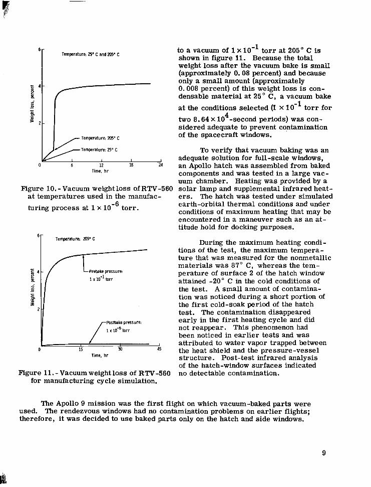
installation inthe spacecraft. This proc- e s s was used with success in reducing the Gemini window contamination (ref. 3). In applying a vacuum bake, it is desirable to use as high a temperature as possible in the thermal-vacuum exposure. However, at high temperatures (approximately 250" C), polymer degradation is possible. There- fore, a temperature of 205" C was chosen as the maximum allowed in the vacuum bake. At this temperature, the weight loss levels off (fig. 10). This condition indicates no major thermally induced polymer degradation has occurred.
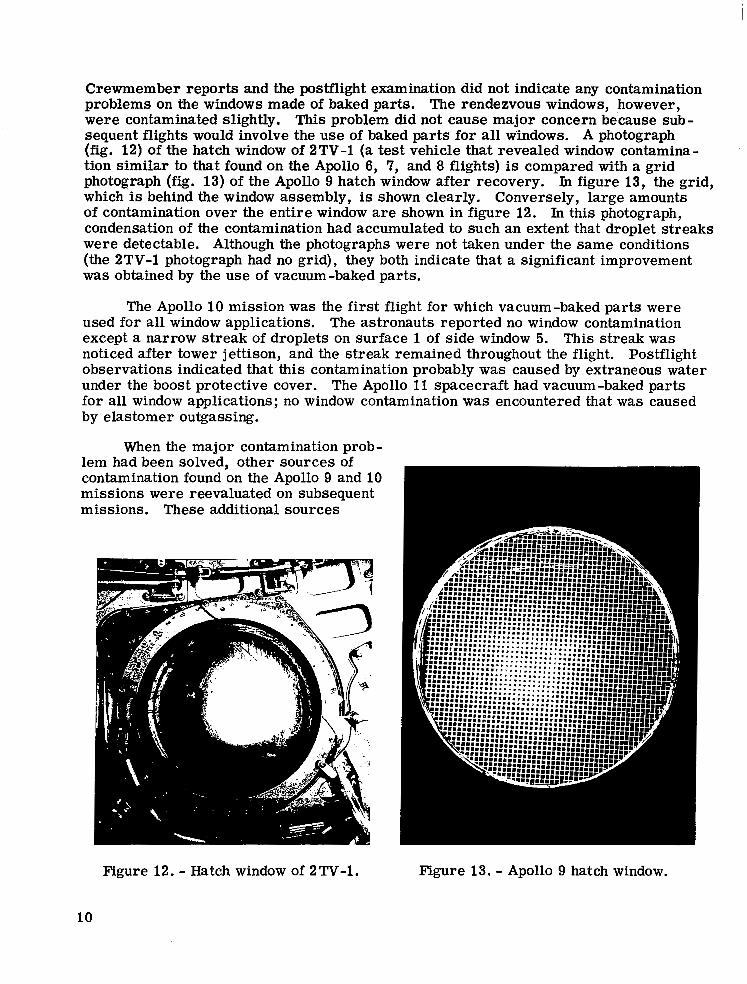
Further considerations of the corrective action indicated that the vacuum bake should be conducted at low pressures and for long periods of time. However, because of limited chamber availability, a maximum pressure of 1 x 10⁻¹ torr was allowed, and an exposure time of 1.72 X 10 seconds (48 hours), divided into two 8.64 X 10 -second (24 hours) steps, was used. The weight loss during and after exposure of the materials
5 4
8
Temperature: 25. C and 205. C
i 2l - Temperature 205" C
I I ~
0 6 12 18 24 Time, hr
Figure 10. - Vacuum weight loss of RTV-560 at temperatures used in the manufac- turing process at 1 x torr .
6r Temperature: 205' C
LPrebake pressure
1 x IO" torr
r h s t b a k e pressure
1 x torr
I 0 15 30 45
Time, hr
Figure 11. - Vacuum weight loss of RTV-560 for manufacturing cycle simulation.
to a vacuum of 1 x 10⁻¹ t o r r at 205" C is shown in figure 11. Because the total weight loss after the vacuum bake is small (approximately 0.08 percent) and because only a small amount (approximately 0.008 percent) of this weight loss is con- densable material at 25" Cy a vacuum bake at the conditions selected (1 X 10⁻¹ t o r r for two 8.64 x 10 -second periods) was con- sidered adequate to prevent contamination of the spacecraft windows.
4
To verify that vacuum baking was an adequate solution for full-scale windows, an Apollo hatch was assembled from baked components and was tested in a large vac- uum chamber. Heating was provided by a solar lamp and supplemental infrared heat- ers. The hatch was tested under simulated earth-orbital thermal conditions and under conditions of maximum heating that may be encountered in a maneuver such as an at- titude hold for docking purposes.
During the maximum heating condi- tions of the test, the maximum tempera- ture that was measured for the nonmetallic materials was 87" C , whereas the tem- perature of surface 2 of the hatch window attained -20" C in the cold conditions of the test. A small amount of contamina- tion was noticed during a short portion of the first cold-soak period of the hatch test. The contamination disappeared early in the first heating cycle and did not reappear. This phenomenon had been noticed in ear l ier tests and was attributed to water vapor trapped between the heat shield and the pressure-vessel structure. Post-test infrared analysis of the hatch-window surfaces indicated no detectable contamination.
The Apollo 9 mission was the first flight on which vacuum-baked parts were used. The rendezvous windows had no contamination problems on earlier flights; therefore, it was decided to use baked parts only on the hatch and side windows.
9
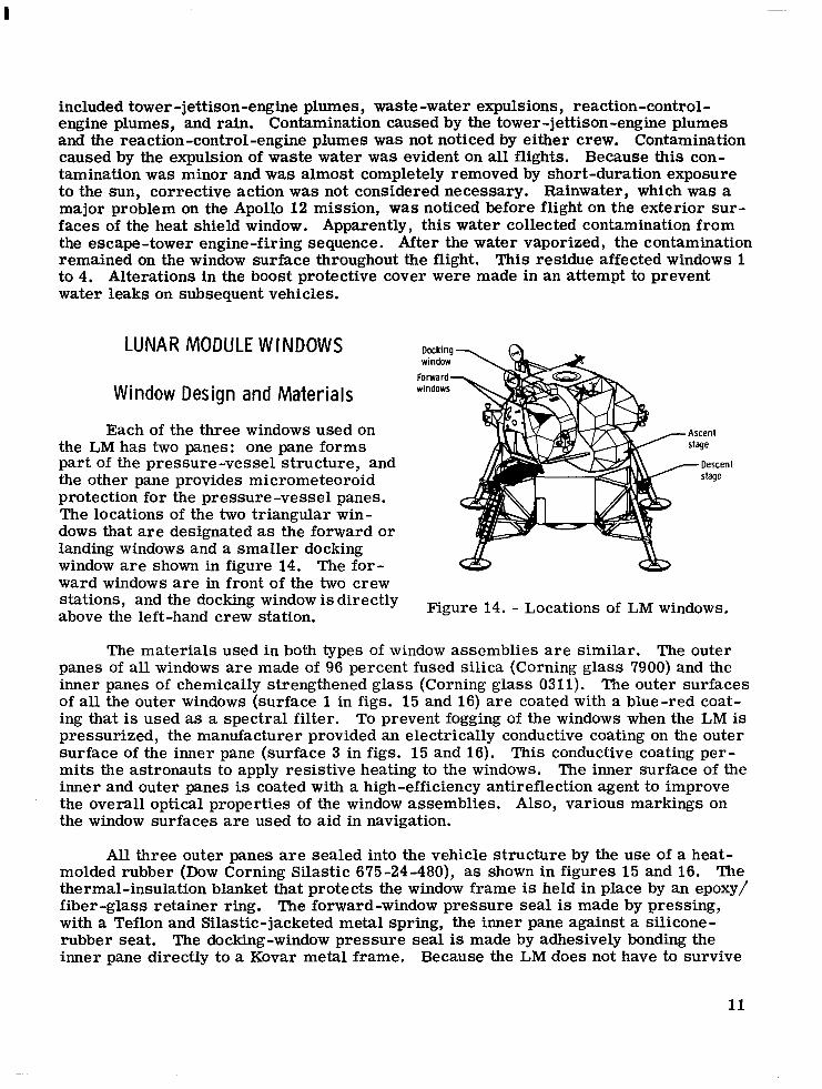
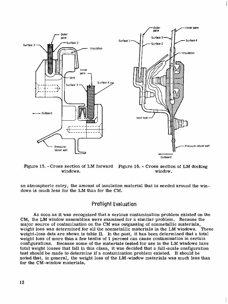
Crewmember reports and the postflight examination did not indicate any contamination problems on the windows made of baked parts. The rendezvous windows, however, were contaminated slightly. This problem did not cause major concern because sub- sequent flights would involve the use of baked parts for all Uiindows. A photograph (fig. 12) of the hatch window of 2TV-1 (a test vehicle that revealed window contamina- tion similar to that found on the Apollo 6, 7, and 8 flights) is compared with a grid photograph (fig. 13) of the Apollo 9 hatch window after recovery. In figure 13, the grid, which is behind the window assembly, is shown clearly. Conversely, large amounts of contamination over the entire window are shown in figure 12. In this photograph, condensation of the contamination had accumulated to such an extent that droplet streaks were detectable. Although the photographs were not taken under the same conditions (the 2TV-1 photograph had no grid), they both indicate that a significant improvement was obtained by the use of vacuum-baked parts.
The Apollo 10 mission was the first flight for which vacuum-baked parts were used for all window applications. The astronauts reported no window contamination except a narrow streak of droplets on surface 1 of side window 5. This streak was noticed after tower jettison, and the streak remained throughout the flight. Postflight observations indicated that this contamination probably was caused by extraneous water under the boost protective cover. The Apollo 11 spacecraft had vacuum-baked parts for all window applications; no window contamination was encountered that was caused by elastomer outgassing.
When the major contamination prob- lem had been solved, other sources of contamination found on the Apollo 9 and 10 missions were reevaluated on subsequent missions. These additional sources
Figure 12. - Hatch window of 2TV-1.
10
Figure 13. - Apollo 9 hatch window.
included tower -jettison-engine plumes, waste-water expulsions, reaction-control- engine plumes, and rain. Contamination caused by the tower-jettison-engine plumes and the reaction-control-engine plumes was not noticed by either crew. Contamination caused by the expulsion of waste water was evident on all flights. Because this con- tamination was minor and was almost completely removed by short-duration exposure to the sun, corrective action was not considered necessary. Rainwater, which was a major problem on the Apollo 12 mission, was noticed before flight on the exterior sur- faces of the heat shield window. Apparently, this water collected contamination from the escape-tower engine-firing sequence. After the water vaporized, the contamination remained on the window surface throughout the flight. This residue affected windows 1 to 4. Alterations in the boost protective cover were made in an attempt to prevent water leaks on subsequent vehicles.
LUNAR MODULE WINDOWS
Window Design and Materials
Each of the three windows used on the LM has two panes: one pane forms part of the pressure-vessel structure, and the other pane provides micrometeoroid protection for the pressure -vessel panes. The locations of the two triangular win- dows that are designated as the forward or landing windows and a smaller docking window a r e shown in figure 14. The for- ward windows are in front of the two crew stations, and the docking window is directly above the left-hand crew station.
Docking window
Forward- windows
Figure 14. - Locations of LM windows.
The materials used in both types of window assemblies are similar. The outer panes of all windows are made of 96 percent fused silica (Corning glass 7900) and the inner panes of chemically strengthened glass (Corning glass 0311). The outer surfaces of all the outer windows (surface 1 in figs. 15 and 16) are coated with a blue-red coat- ing that is used as a spectral filter. To prevent fogging of the windows when the LM is pressurized, the manufacturer provided an electrically conductive coating on the outer surface of the inner pane (surface 3 in figs. 15 and 16). This conductive coating per- mits the astronauts to apply resistive heating to the windows. The inner surface of the inner and outer panes is coated with a high-efficiency antireflection agent to improve the overall optical properties of the window assemblies. Also, various markings on the window surfaces are used to aid in navigation.
All three outer panes are sealed into the vehicle structure by the use of a heat- molded rubber (Dow Corning Silastic 675-24-480), as shown in figures 15 and 16. The thermal-insulation blanket that protects the window frame is held in place by an epoxy/ fiber-glass retainer ring. The forward-window pressure seal is made by pressing, with a Teflon and Silastic-jacketed metal spring, the inner pane against a silicone- rubber seat. The docking-window pressure seal is made by adhesively bonding the inner pane directly to a Kovar metal frame. Because the LM does not have to survive
11
f-
- Outboard
Figure 15. - Cross section of LM forward windows.
Surface 1
B- Pressure-vessel wall
Outboard
Figure 16. - Cross section of LM docking window.
an atmospheric entry, the amount of insulation material that is needed around the win- dows is much less for the LM than for the CM.
Preflight Evaluation
As soon as it was recognized that a serious contamination problem existed on the CM, the LM window assemblies were examined for a similar problem. Because the major source of contamination on the CM was outgassing of nonmetallic materials, weight loss was determined for all the nonmetallic materials in the LM windows. These weight-loss data are shown in table 11. In the past, it has been determined that a total weight loss of more than a few tenths of 1 percent can cause contamination in certain configurations. Because some of the materials tested for use in the LM windows have total weight losses that fall in this class, it was decided that a full-scale configuration test should be made to determine if a contamination problem existed. It should be noted that, in general, the weight loss of the LM-window materials was much less than for the CM-window materials.
12
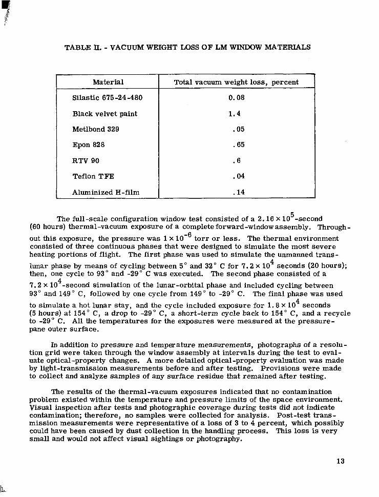
TABLE II. - VACUUM WEIGHT LOSS O F LM WINDOW MATERIALS
~
Material
Silastic 675 -24-480
Black velvet paint
Metlbond 329
Epon 828
RTV 90
Teflon TFE
Aluminized H-film
-~
Total vacuum weight loss, percent
0.08
1.4
.05
.65
.6
.04
-14
The full-scale configuration window test consisted of a 2.16 X 10 -second (60 hours) thermal-vacuum exposure of a complete forward-window assembly. Through- out this exposure, the pressure was 1 x lom6 t o r r o r less. The thermal environment consisted of three continuous phases that were designed to simulate the most severe heating portions of flight. The first phase was used to simulate the unmanned trans- lunar phase by means of cycling between 5" and 32" C for 7 .2 x 10 seconds (20 hours); then, one cycle to 93" and -29" C was executed. The second phase consisted of a 7.2 X 10 -second simulation of the lunar-orbital phase and included cycling between 93" and 149 " C, followed by one cycle from 149" to -29" C. The final phase was used to simulate a hot lunar stay, and the cycle included exposure for 1.8 X 10 seconds (5 hours) a t 154" C, a drop to -29" C, a short-term cycle back to 154" C, and a recycle to -29 " C. All the temperatures for the exposures were measured at the pressure- pane outer surface.
5
4
4
4
In addition to pressure and temperature measurements, photographs of a resolu- tion grid were taken through the window assembly at intervals during the test to eval- uate optical-property changes. A more detailed optical-property evaluation was made by light-transmission measurements before and after testing. Provisions were made to collect and analyze samples of any surface residue that remained after testing.
The results of the thermal-vacuum exposures indicated that no contamination problem existed within the temperature and pressure limits of the space envi,ronment. Visual inspection after tests and photographic coverage during tests did not indicate contamination; therefore, no samples were collected for analysis. Post-test trans- mission measurements were representative of a loss of 3 to 4 percent, which possibly could have been caused by dust collection in the handling process. This loss is very small and would not affect visual sightings o r photography.
13
I 111 I I I
I nflight Evaluation
I I I .I11 I I
An evaluation of the LM window performance was first obtained on the Apollo 9 mission. On this and all subsequent LM flights, the astronauts detected no unexpected contamination on the windows. As expected, upon pressurization of the LM, water condenses and collects on the inner surfaces of the inner panes. This condensate is removed by activation of the window heaters. In general, it can be concluded that the LM windows performed satisfactorily.
The relatively contamination-free condition of these windows might seem sur- prising because it was indicated earlier that the weight loss of the materials that were used in construction was rather large in some instances. However, if table It and figures 15 and 16 are examined, it is clear that the materials that sustain large weight losses are used in very limited amounts and, in general, are not exposed to the area between the panes. There is one exception: the fiber-glass retainer that involves an epoxy as the matrix material. The weight loss for this material was 0.65 percent. Because no contamination problem was encountered, the amount of condensable out- gassing products from the epoxy was assumed to be very low.
CONCLUDING REMARKS
All window assemblies in the Apollo spacecraft were examined for contamination problems. Primarily, reduction of the optical properties of the command module win- dows was caused by the contamination from outgassing of silicone sealants that were used in the vicinity of the windows. This contamination was reduced to an acceptable level, with respect to mission objectives, by means of vacuum baking the silicone sealants.
The lunar module windows also were examined for the contamination problems. A test program on the individual materials that were used in the window-assembly construction and a full-scale configuration test indicated that no significant contamina- tion problems existed on the lunar module window assemblies. The results of inflight evaluations substantiated this conclusion.
As far as contamination is concerned, the best spacecraft-window design should involve the use of a direct glass-to-metal seal. Currently, such a design is not prac- tical for windows larger than approximately 4 inches in diameter; nonmetallic seals must be used. Even for an application such as in the Apollo Program, the use of nonmetallic materials around optical surfaces must be controlled very closely. For these applica- tions, the first choice for a sealant material should be heat-molded elastomers that can be cured at elevated temperatures and low pressures. If a room-temperature- vulcanizing agent is required, new products have become available recently. These new products have superior outgassing properties, and weight-loss values (in a thermal- vacuum environment) for these products are quite low and are comparable to the weight loss of the vacuum-baked parts that are used on the Apollo spacecraft.
14
Window seals and sealants are indeed important when contamination problems are considered. However, as was evident on the Apollo command module, the overall win- dow design must be considered also. Materials that are used in the main or supporting structure, as well as in other applications near the window assembly, must be tested to ensure low outgassing rates. Such an approach was important during the Apollo Program and will be even more important in future programs.
Manned Spacecraft Center National Aeronautics and Space Administration
Houston, Texas, September 17, 1971 914-13-20-21-72
REFERENCES
1. Anon. : Mercury Project Summary Including Results of the Fourth Manned Orbital Flight May 15 and 16, 1963. NASA SP-45, 1963.
2. Anon. : Results of the Third United States Manned Orbital Space Flight, October 3, 1962. NASA SP-12, 1962.
3. Blome, James C. ; and Upton, Bruce E. : Gemini Window Contamination Due to Outgassing of Silicones. Proceedings of the 11th National Symposium and Ex- hibit of the Society of Aerospace Material and Process Engineers, Science of Advanced Materials and Process Engineering Series, vol. 11, 1967, pp. 217-225.
4. Kimball, L. G. : Postflight Investigation of Apollo Command Module 101 Windows. Rept. NA-68-922, Los Angeles Division, North American Rockwell, Dec. 1968.
NASA-Langley, 1912 - 31 S -2 84 15