Embed Size (px)
Citation preview
Loadbalancer.org
Loadbalancer.org appliance quick setup guide
v6.6
1

Confidentiality StatementAll information contained in this proposal is provided in confidence for the sole purpose of adjudication of the contents and shall not be published or disclosed wholly or in part to any other party without Loadbalancer.org's prior permission in writing, and shall be held in safe custody. These obligations shall not apply to information that is published or becomes known legitimately from some source other than Loadbalancer.org.
Copyright
Loadbalancer.org 2009
Registered office: 1 High Street, Knaphill, Woking, Surrey, GU21 2PG
2
Loadbalancer.org quick start guide v6.6
Loadbalancer.org terminology..............................................................................................................4What is a virtual IP address?.......................................................................................................4What is a floating IP address?.....................................................................................................4
What are your objectives?................................................................................................................5What is the difference between a one-arm and a two-arm configuration?......................................6What are the different load balancing methods supported?.............................................................7
Network diagram: one arm – DR Direct Routing (single unit) ..................................................9Network diagram: two arm - NAT Network Address Translation (single unit)........................10High-availability configuration of two Loadbalancer.org appliances.......................................11Network diagram: two arm - NAT Network Address Translation (clustered pair)...................11Network diagram: one arm – DR Direct Routing (clustered pair) ...........................................12
Setting up the Loadbalancer.org Virtual Appliance.......................................................................13Configuring the Loadbalancer.org appliance using the web based wizard....................................14
Network interface configuration...............................................................................................14Configuring the Loadbalancer.org appliance using the console wizard........................................15
Network interface configuration...............................................................................................15Flow diagram explanation of the wizards.................................................................................16Example answers using the wizard for a two-arm NAT configuration.....................................18
Additional Loadbalancer.org configuration (web interface)..........................................................19Additional real servers (web interface)..........................................................................................20Real server (back end) configuration for NAT mode.....................................................................21Real server (back end) configuration for DR mode (Linux).........................................................21Real server (back end) configuration for DR mode (Windows)....................................................22
Resolving ARP issues for Windows server 2000 & 2003 (DR mode only)..............................23Installing the Microsoft loopback adapter:...........................................................................23Configuring the loopback adapter........................................................................................24
Resolving ARP issues for Windows server 2008 (DR mode only)...........................................26Weak and strong host behavior in Windows .......................................................................26
Testing the load balancer configuration.........................................................................................28Connection error diagnosis ......................................................................................................28Health check diagnosis..............................................................................................................29Testing high-availability for a Loadbalancer.org HA-pair........................................................29
Does your application cluster correctly handle its own state?.......................................................30Replication solutions for shared data:.......................................................................................30Solutions for session data:.........................................................................................................30What do you do if your application is not stateless?.................................................................31Loadbalancer.org persistence methods......................................................................................31
Loadbalancer.org technical support...............................................................................................31Loadbalancer.org hardware support...............................................................................................31
3
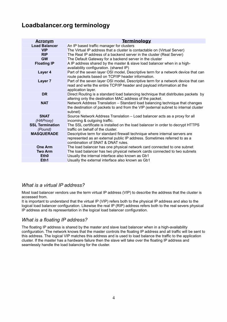
Loadbalancer.org terminology
Acronym TerminologyLoad Balancer An IP based traffic manager for clusters
VIP The Virtual IP address that a cluster is contactable on (Virtual Server)RIP The Real IP address of a backend server in the cluster (Real Server)GW The Default Gateway for a backend server in the cluster
Floating IP A IP address shared by the master & slave load balancer when in a high-availability configuration. (shared IP)
Layer 4 Part of the seven layer OSI model, Descriptive term for a network device that can route packets based on TCP/IP header information.
Layer 7 Part of the seven layer OSI model, Descriptive term for a network device that can read and write the entire TCP/IP header and payload information at the application layer.
DR Direct Routing is a standard load balancing technique that distributes packets by altering only the destination MAC address of the packet.
NAT Network Address Translation – Standard load balancing technique that changes the destination of packets to and from the VIP (external subnet to internal cluster subnet)
SNAT(HAProxy)
Source Network Address Translation – Load balancer acts as a proxy for all incoming & outgoing traffic.
SSL Termination(Pound)
The SSL certificate is installed on the load balancer in order to decrypt HTTPS traffic on behalf of the cluster.
MASQUERADE Descriptive term for standard firewall technique where internal servers are represented as an external public IP address. Sometimes referred to as a combination of SNAT & DNAT rules.
One Arm The load balancer has one physical network card connected to one subnetTwo Arm The load balancer has two physical network cards connected to two subnets
Eth0 Usually the internal interface also known as Gb1Eth1 Usually the external interface also known as Gb1
What is a virtual IP address?
Most load balancer vendors use the term virtual IP address (VIP) to describe the address that the cluster is accessed from.It is important to understand that the virtual IP (VIP) refers both to the physical IP address and also to the logical load balancer configuration. Likewise the real IP (RIP) address refers both to the real severs physical IP address and its representation in the logical load balancer configuration.
What is a floating IP address?
The floating IP address is shared by the master and slave load balancer when in a high-availability configuration. The network knows that the master controls the floating IP address and all traffic will be sent to this address. The logical VIP matches this address and is used to load balance the traffic to the application cluster. If the master has a hardware failure then the slave will take over the floating IP address and seamlessly handle the load balancing for the cluster.
4
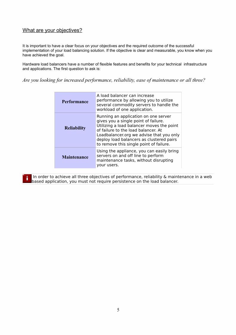
What are your objectives?
It is important to have a clear focus on your objectives and the required outcome of the successful implementation of your load balancing solution. If the objective is clear and measurable, you know when you have achieved the goal.
Hardware load balancers have a number of flexible features and benefits for your technical infrastructure and applications. The first question to ask is:
Are you looking for increased performance, reliability, ease of maintenance or all three?
PerformanceA load balancer can increase performance by allowing you to utilize several commodity servers to handle the workload of one application.
Reliability
Running an application on one server gives you a single point of failure. Utilizing a load balancer moves the point of failure to the load balancer. At Loadbalancer.org we advise that you only deploy load balancers as clustered pairs to remove this single point of failure.
MaintenanceUsing the appliance, you can easily bring servers on and off line to perform maintenance tasks, without disrupting your users.
In order to achieve all three objectives of performance, reliability & maintenance in a web based application, you must not require persistence on the load balancer.
5

What is the difference between a one-arm and a two-arm configuration?
The number of 'arms' is a descriptive term for how many physical connections (Ethernet ports or cables) are used to connect the load balancers to the network. It is very common for load balancers that use a routing method (NAT) to have a two arm configuration. Proxy based load balancers (SNAT) commonly use a one arm configuration.
NB. To add even more confusion, having a 'one arm' or 'two arm' solution may or may not imply the same number of network cards.
Loadbalancer.org topology definition:
One Arm The load balancer has one physical network card connected to one subnet.
Two Arm The load balancer has two physical network cards connected to two subnets.
6
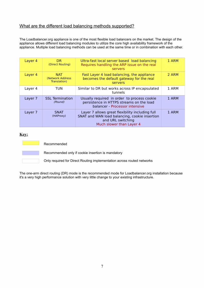
What are the different load balancing methods supported?
The Loadbalancer.org appliance is one of the most flexible load balancers on the market. The design of the appliance allows different load balancing modules to utilize the core high availability framework of the appliance. Multiple load balancing methods can be used at the same time or in combination with each other.
Layer 4 DR (Direct Routing)
Ultra-fast local server based load balancingRequires handling the ARP issue on the real
servers
1 ARM
Layer 4 NAT(Network Address
Translation)
Fast Layer 4 load balancing, the appliance becomes the default gateway for the real
servers
2 ARM
Layer 4 TUN Similar to DR but works across IP encapsulated tunnels
1 ARM
Layer 7 SSL Termination(Pound)
Usually required in order to process cookie persistence in HTTPS streams on the load
balancer - Processor intensive
1 ARM
Layer 7 SNAT(HAProxy)
Layer 7 allows great flexibility including full SNAT and WAN load balancing, cookie insertion
and URL switchingMuch slower than Layer 4
1 ARM
Key:
Recommended
Recommended only if cookie insertion is mandatory
Only required for Direct Routing implementation across routed networks
The one-arm direct routing (DR) mode is the recommended mode for Loadbalancer.org installation because it's a very high performance solution with very little change to your existing infrastructure.
7
Sometimes it is not possible to use DR mode. The two most common reasons being: if the application cannot bind to RIP & VIP at the same time; or if the host operating system
cannot be modified to handle the ARP issue (see real server configuration section).
The second choice is Network Address Translation (NAT) mode. This is also a fairly high performance solution but it requires the implementation of a two arm infrastructure with an internal and external subnet to carry out the translation (the same way a firewall works).
Network engineers with experience of hardware load balancers will have often used this method.
If your application requires that the load balancer handles cookie insertion then you need to use the SNAT configuration. This also has the advantage of a one arm configuration and does not require any changes to the application servers. However, as the load balancer is acting as a full proxy it doesn't have the same raw throughput as the routing based methods. Please refer to the administration manual for configuration of SSL termination or cookie insertion.
The following section describes the different network configuration possibilities for NAT & DR mode in more detail.
If your application doesn't maintain its own state information then you may need to use cookie insertion, please refer to the full administration manual for configuration details.
8
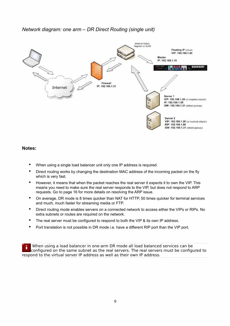
Network diagram: one arm – DR Direct Routing (single unit)
Notes:
• When using a single load balancer unit only one IP address is required.
• Direct routing works by changing the destination MAC address of the incoming packet on the fly which is very fast.
• However, it means that when the packet reaches the real server it expects it to own the VIP. This means you need to make sure the real server responds to the VIP, but does not respond to ARP requests. Go to page 16 for more details on resolving the ARP issue.
• On average, DR mode is 8 times quicker than NAT for HTTP, 50 times quicker for terminal services and much, much faster for streaming media or FTP.
• Direct routing mode enables servers on a connected network to access either the VIPs or RIPs. No extra subnets or routes are required on the network.
• The real server must be configured to respond to both the VIP & its own IP address.
• Port translation is not possible in DR mode i.e. have a different RIP port than the VIP port.
When using a load balancer in one-arm DR mode all load balanced services can be configured on the same subnet as the real servers. The real servers must be configured to
respond to the virtual server IP address as well as their own IP address.
9
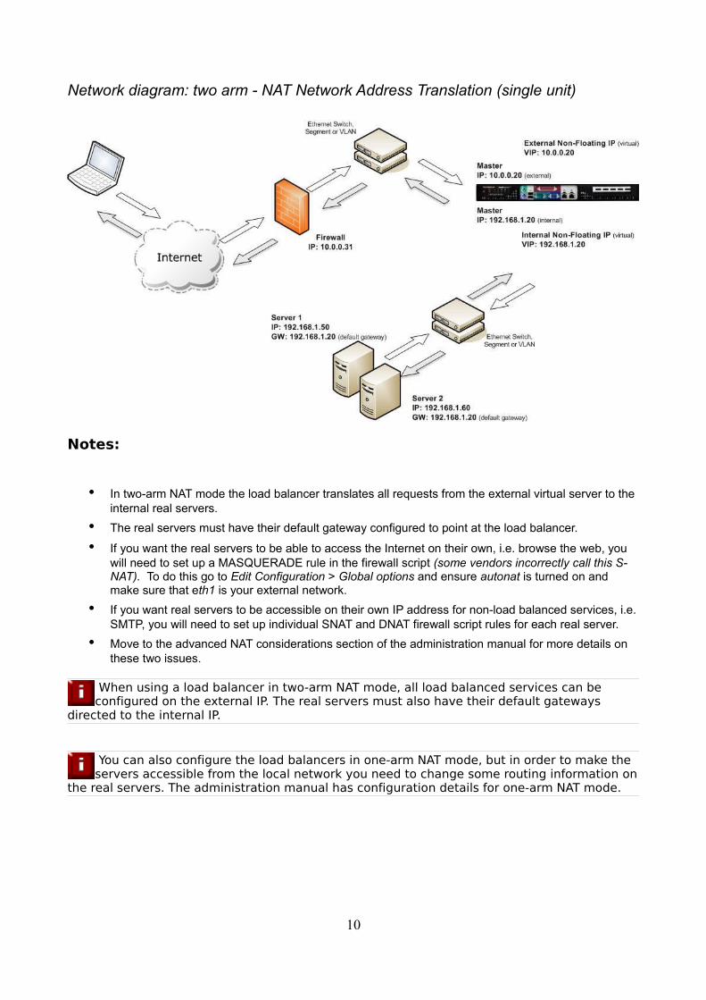
Network diagram: two arm - NAT Network Address Translation (single unit)
Notes:
• In two-arm NAT mode the load balancer translates all requests from the external virtual server to the internal real servers.
• The real servers must have their default gateway configured to point at the load balancer.
• If you want the real servers to be able to access the Internet on their own, i.e. browse the web, you will need to set up a MASQUERADE rule in the firewall script (some vendors incorrectly call this S-NAT). To do this go to Edit Configuration > Global options and ensure autonat is turned on and make sure that eth1 is your external network.
• If you want real servers to be accessible on their own IP address for non-load balanced services, i.e. SMTP, you will need to set up individual SNAT and DNAT firewall script rules for each real server.
• Move to the advanced NAT considerations section of the administration manual for more details on these two issues.
When using a load balancer in two-arm NAT mode, all load balanced services can be configured on the external IP. The real servers must also have their default gateways
directed to the internal IP.
You can also configure the load balancers in one-arm NAT mode, but in order to make the servers accessible from the local network you need to change some routing information on
the real servers. The administration manual has configuration details for one-arm NAT mode.
10
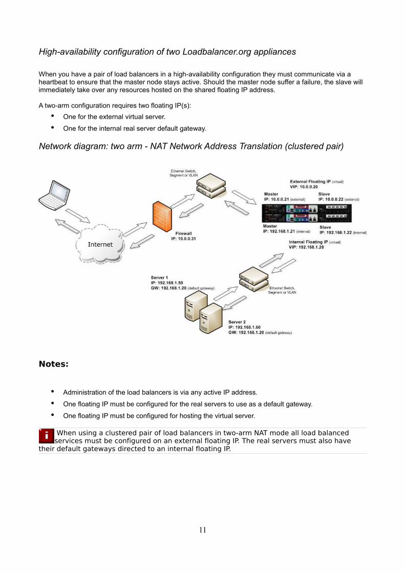
High-availability configuration of two Loadbalancer.org appliances
When you have a pair of load balancers in a high-availability configuration they must communicate via a heartbeat to ensure that the master node stays active. Should the master node suffer a failure, the slave will immediately take over any resources hosted on the shared floating IP address.
A two-arm configuration requires two floating IP(s):
• One for the external virtual server.
• One for the internal real server default gateway.
Network diagram: two arm - NAT Network Address Translation (clustered pair)
Notes:
• Administration of the load balancers is via any active IP address.
• One floating IP must be configured for the real servers to use as a default gateway.
• One floating IP must be configured for hosting the virtual server.
When using a clustered pair of load balancers in two-arm NAT mode all load balanced services must be configured on an external floating IP. The real servers must also have
their default gateways directed to an internal floating IP.
11
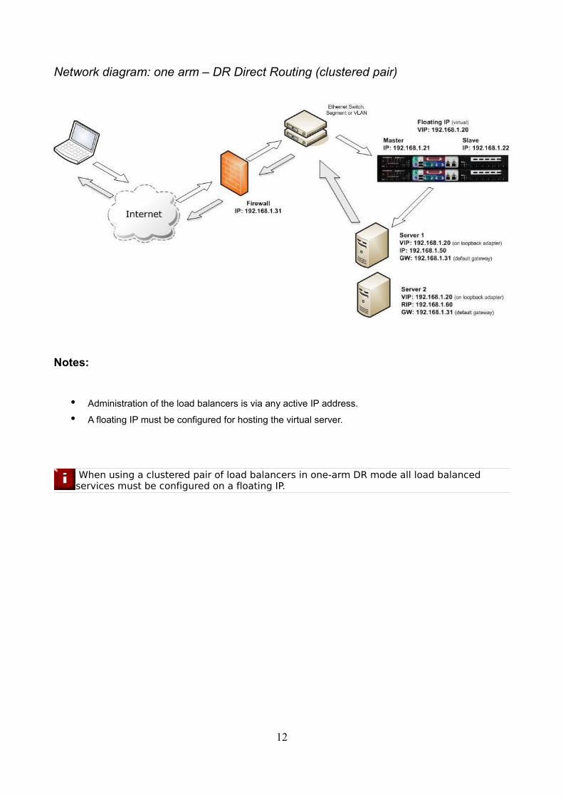
Network diagram: one arm – DR Direct Routing (clustered pair)
Notes:
• Administration of the load balancers is via any active IP address.
• A floating IP must be configured for hosting the virtual server.
When using a clustered pair of load balancers in one-arm DR mode all load balanced services must be configured on a floating IP.
12
Setting up the Loadbalancer.org Virtual Appliance
1. For VMware Server or player download the LBVM.zip file
2. Extract the file
3. Use either VMware Player, Server or ESX (either import or use our ESX only image)
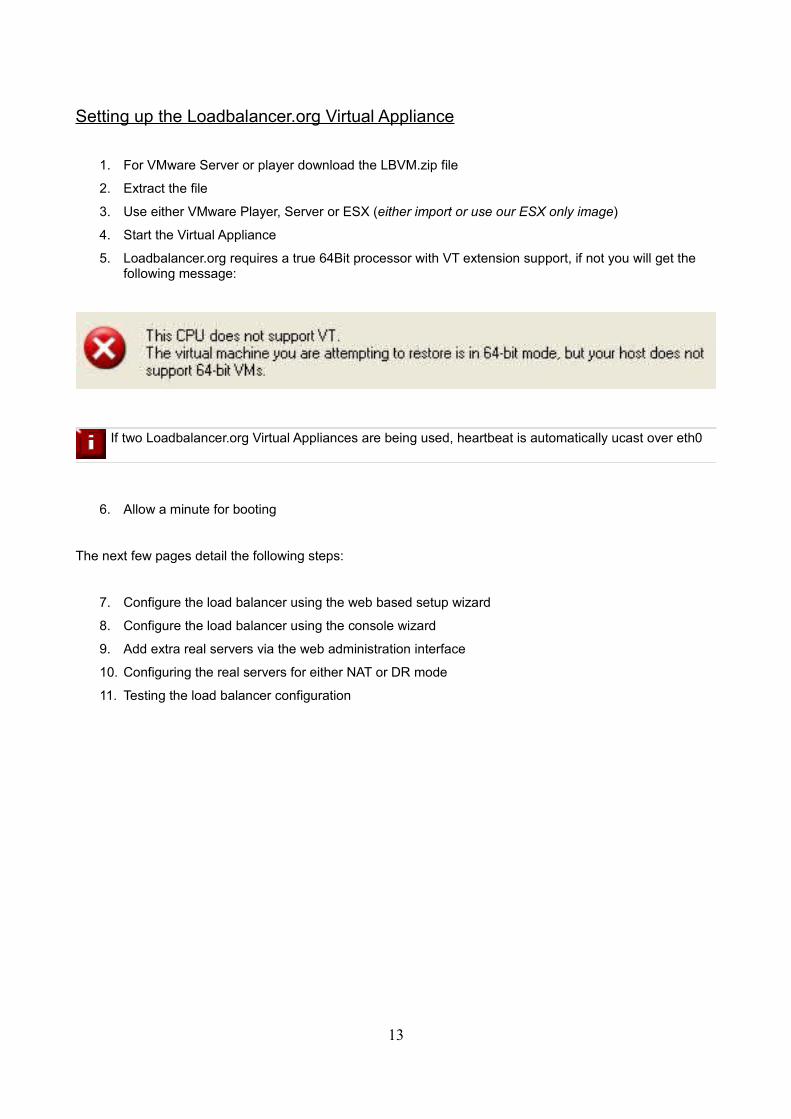
4. Start the Virtual Appliance
5. Loadbalancer.org requires a true 64Bit processor with VT extension support, if not you will get the following message:
If two Loadbalancer.org Virtual Appliances are being used, heartbeat is automatically ucast over eth0
6. Allow a minute for booting
The next few pages detail the following steps:
7. Configure the load balancer using the web based setup wizard
8. Configure the load balancer using the console wizard
9. Add extra real servers via the web administration interface
10. Configuring the real servers for either NAT or DR mode
11. Testing the load balancer configuration
13
Configuring the Loadbalancer.org appliance using the web based wizard
This section deals with the process of configuring a single load balancer appliance via the web based wizard. The web based wizard enables you to configure a complete working configuration with one virtual server and one real server. You can then continue in the web interface to make modifications to this basic configuration.
Network interface configuration
• Power up the load balancer
• Log in with:
• Username: root
• Password: loadbalancer
You can access the web interface (and subsequently the web based wizard) either via links at the console or from a web browser on a client connected to the same network (recommended).
With a web browser access the web interface i.e. http://192.168.2.21:9080/lbadmin/
(replace 192.168.2.21 with the correct address)
Log in to the web interface:
User: loadbalancerPassword: loadbalancer
NB. If you prefer you can use the HTTPS administration address : https://192.168.2.21:9443/lbadmin/
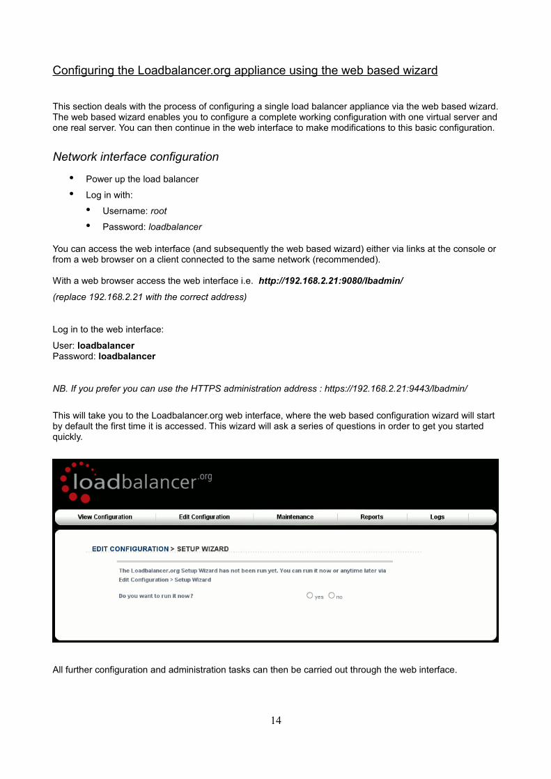
This will take you to the Loadbalancer.org web interface, where the web based configuration wizard will start by default the first time it is accessed. This wizard will ask a series of questions in order to get you started quickly.
All further configuration and administration tasks can then be carried out through the web interface.
14
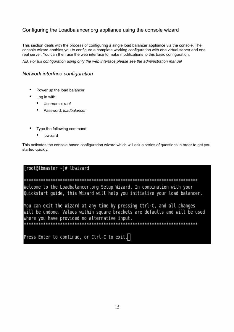
Configuring the Loadbalancer.org appliance using the console wizard
This section deals with the process of configuring a single load balancer appliance via the console. The console wizard enables you to configure a complete working configuration with one virtual server and one real server. You can then use the web interface to make modifications to this basic configuration.
NB. For full configuration using only the web interface please see the administration manual
Network interface configuration
• Power up the load balancer
• Log in with:
• Username: root
• Password: loadbalancer
• Type the following command:
• lbwizard
This activates the console based configuration wizard which will ask a series of questions in order to get you started quickly.
15
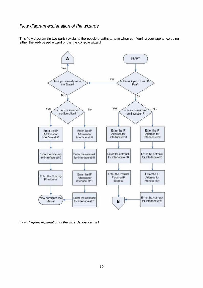
Flow diagram explanation of the wizards
This flow diagram (in two parts) explains the possible paths to take when configuring your appliance using either the web based wizard or the the console wizard:
Flow diagram explanation of the wizards, diagram #1
16
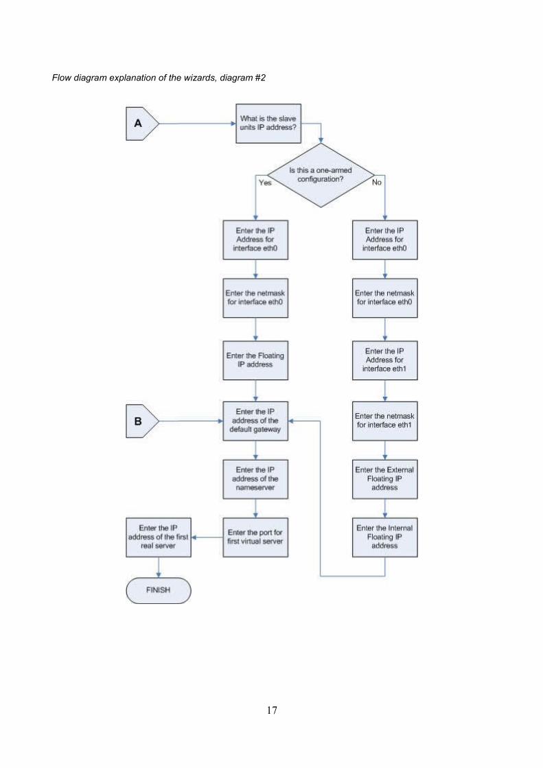
Flow diagram explanation of the wizards, diagram #2
17
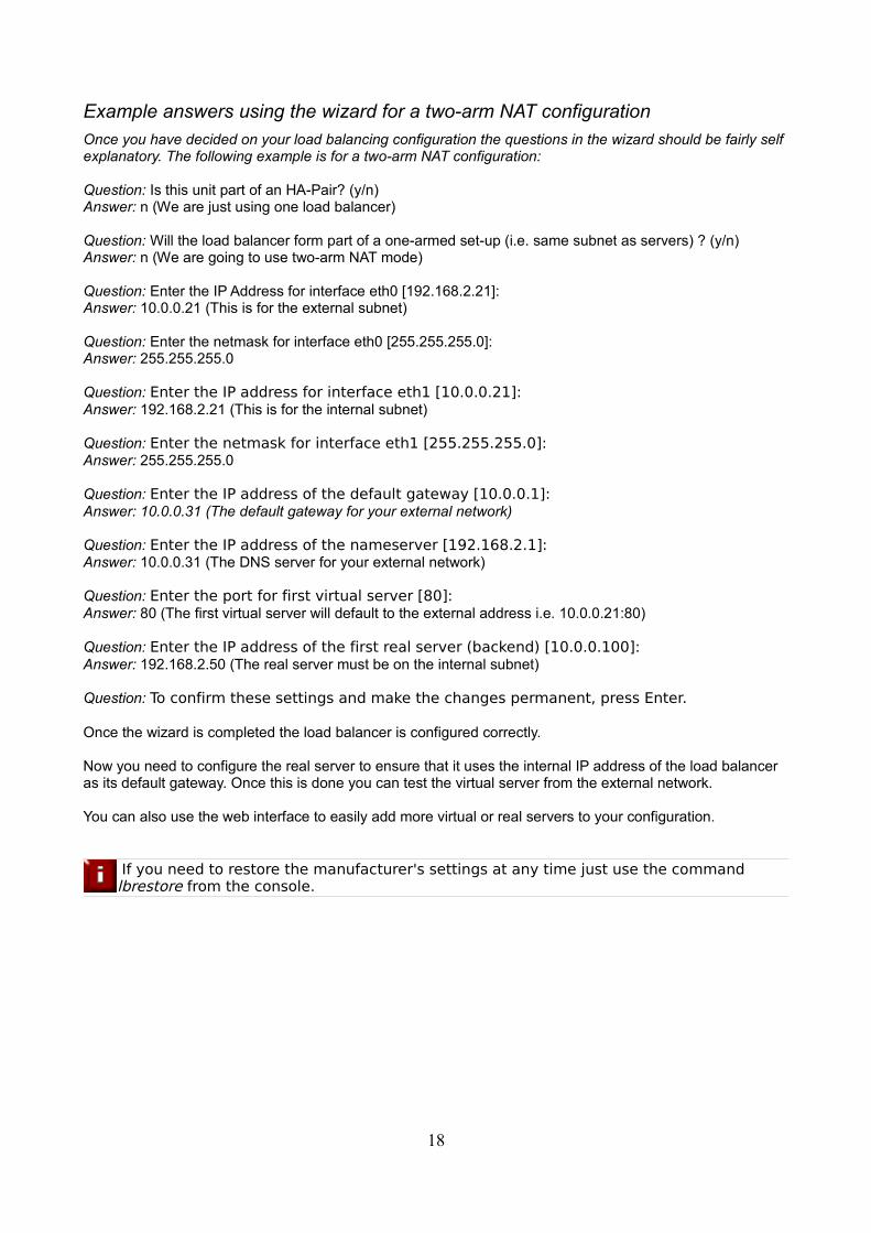
Example answers using the wizard for a two-arm NAT configuration
Once you have decided on your load balancing configuration the questions in the wizard should be fairly self explanatory. The following example is for a two-arm NAT configuration:
Question: Is this unit part of an HA-Pair? (y/n)Answer: n (We are just using one load balancer)
Question: Will the load balancer form part of a one-armed set-up (i.e. same subnet as servers) ? (y/n)Answer: n (We are going to use two-arm NAT mode)
Question: Enter the IP Address for interface eth0 [192.168.2.21]:Answer: 10.0.0.21 (This is for the external subnet)
Question: Enter the netmask for interface eth0 [255.255.255.0]:Answer: 255.255.255.0
Question: Enter the IP address for interface eth1 [10.0.0.21]: Answer: 192.168.2.21 (This is for the internal subnet)
Question: Enter the netmask for interface eth1 [255.255.255.0]: Answer: 255.255.255.0
Question: Enter the IP address of the default gateway [10.0.0.1]: Answer: 10.0.0.31 (The default gateway for your external network)
Question: Enter the IP address of the nameserver [192.168.2.1]: Answer: 10.0.0.31 (The DNS server for your external network)
Question: Enter the port for first virtual server [80]: Answer: 80 (The first virtual server will default to the external address i.e. 10.0.0.21:80)
Question: Enter the IP address of the first real server (backend) [10.0.0.100]: Answer: 192.168.2.50 (The real server must be on the internal subnet)
Question: To confirm these settings and make the changes permanent, press Enter.
Once the wizard is completed the load balancer is configured correctly.
Now you need to configure the real server to ensure that it uses the internal IP address of the load balancer as its default gateway. Once this is done you can test the virtual server from the external network.
You can also use the web interface to easily add more virtual or real servers to your configuration.
If you need to restore the manufacturer's settings at any time just use the command lbrestore from the console.
18
Additional Loadbalancer.org configuration (web interface)
This section deals with the configuration of the load balancers via the web interface. The wizard should enable you to have a working virtual server with a single configured real server (back end). You can use the web interface to add or modify existing virtual and real servers as required.
If you used the web based wizard then you will already be in the web interface. From here all administration tasks can be carried out.
If you chose to use the console wizard then you can now access the web interface either via links at the console or from a web browser on a client connected to the same network (recommended).
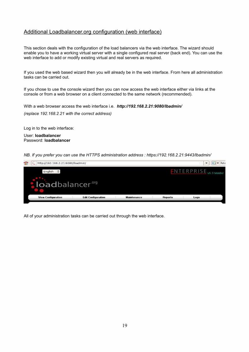
With a web browser access the web interface i.e. http://192.168.2.21:9080/lbadmin/
(replace 192.168.2.21 with the correct address)
Log in to the web interface:
User: loadbalancerPassword: loadbalancer
NB. If you prefer you can use the HTTPS administration address : https://192.168.2.21:9443/lbadmin/
All of your administration tasks can be carried out through the web interface.
19
Additional real servers (web interface)
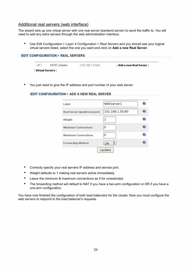
The wizard sets up one virtual server with one real server (backend server) to send the traffic to. You will need to add any extra servers through the web administration interface:
• Use Edit Configuration > Layer 4 Configuration > Real Servers and you should see your logical virtual servers listed, select the one you want and click on Add a new Real Server.
• You just need to give the IP address and port number of your web server.
• Correctly specify your real servers IP address and service port.
• Weight defaults to 1 making real servers active immediately.
• Leave the minimum & maximum connections as 0 for unrestricted.
• The forwarding method will default to NAT if you have a two-arm configuration or DR if you have a one-arm configuration.
You have now finished the configuration of both load balancers for the cluster. Now you must configure the web servers to respond to the load balancer's requests.
20
Real server (back end) configuration for NAT mode
If you are using a two-arm NAT load balancing method the real server configuration is a simple case of configuring the load balancer as the default gateway. The real server must also have a valid IP address in the internal subnet behind the load balancer.
Failure to correctly configure the real servers default gateway is the most common problem in NAT configurations. Please refer to: Advanced NAT considerations in the
administration manual.
Real server (back end) configuration for DR mode (Linux)
If you are using a one-arm DR load balancing method each web server requires the ARP problem to be handled. Every real server must be configured to respond to the VIP address as well as the RIP address. This is because in DR mode load balanced traffic arrives on the VIP address but the load balancer health checks are on the real server's IP address.
You can use iptables (netfilter) on the real server to re-direct incoming packets destined for the virtual server IP address. This is a simple case of adding the following command to your start up script (rc.local):
iptables -t nat -A PREROUTING -p tcp -d 10.0.0.21 -j REDIRECT
i.e. Redirect any incoming packets destined for 10.0.0.21 (virtual server) to my local address.
(Don't forget to change the IP address to be the same as your virtual server)
Failure to correctly configure the real servers to handle the ARP problem is the most common problem in DR configurations. Please refer to: Advanced DR considerations in the
administration manual.
21
Real server (back end) configuration for DR mode (Windows)
If you are using a one-arm DR load balancing method each web server requires the ARP problem to be handled:
• Each server must have the MS loopback adapter installed and configured.
• The MS loopback adapter must be configured to deal with the ARP problem.
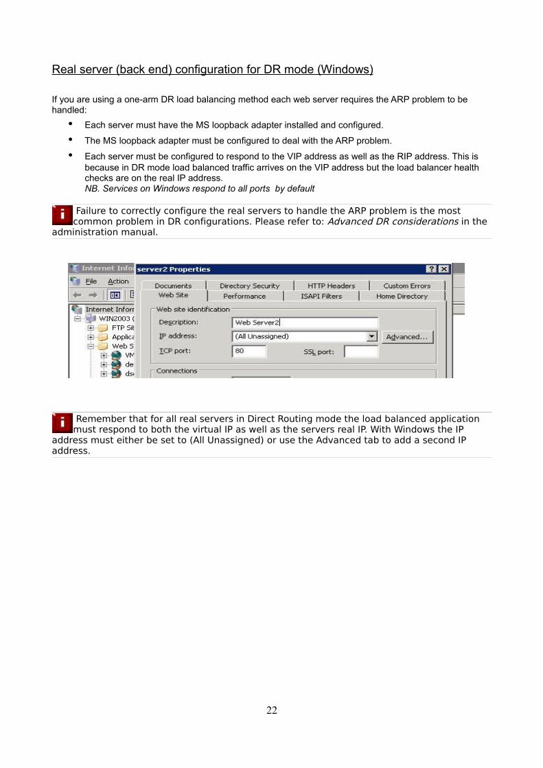
• Each server must be configured to respond to the VIP address as well as the RIP address. This is because in DR mode load balanced traffic arrives on the VIP address but the load balancer health checks are on the real IP address. NB. Services on Windows respond to all ports by default
Failure to correctly configure the real servers to handle the ARP problem is the most common problem in DR configurations. Please refer to: Advanced DR considerations in the
administration manual.
Remember that for all real servers in Direct Routing mode the load balanced application must respond to both the virtual IP as well as the servers real IP. With Windows the IP
address must either be set to (All Unassigned) or use the Advanced tab to add a second IP address.
22
Resolving ARP issues for Windows server 2000 & 2003 (DR mode only)
Windows server supports the direct routing method through the use of the MS loopback adapter to handle the traffic.
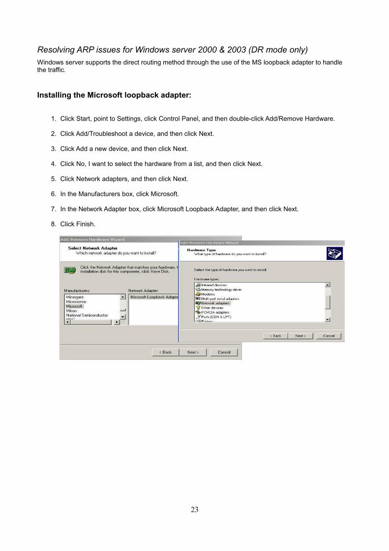
Installing the Microsoft loopback adapter:
1. Click Start, point to Settings, click Control Panel, and then double-click Add/Remove Hardware.
2. Click Add/Troubleshoot a device, and then click Next.
3. Click Add a new device, and then click Next.
4. Click No, I want to select the hardware from a list, and then click Next.
5. Click Network adapters, and then click Next.
6. In the Manufacturers box, click Microsoft.
7. In the Network Adapter box, click Microsoft Loopback Adapter, and then click Next.
8. Click Finish.
23
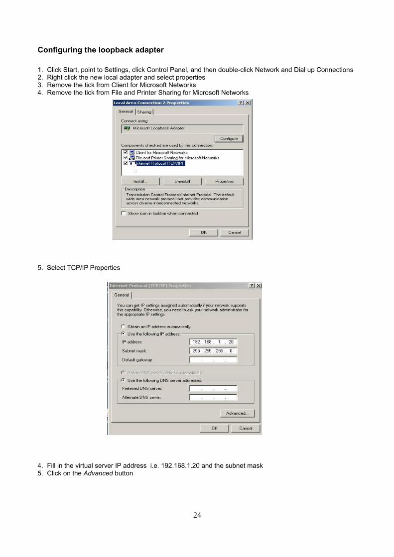
Configuring the loopback adapter
1. Click Start, point to Settings, click Control Panel, and then double-click Network and Dial up Connections2. Right click the new local adapter and select properties3. Remove the tick from Client for Microsoft Networks4. Remove the tick from File and Printer Sharing for Microsoft Networks
5. Select TCP/IP Properties
4. Fill in the virtual server IP address i.e. 192.168.1.20 and the subnet mask5. Click on the Advanced button
24
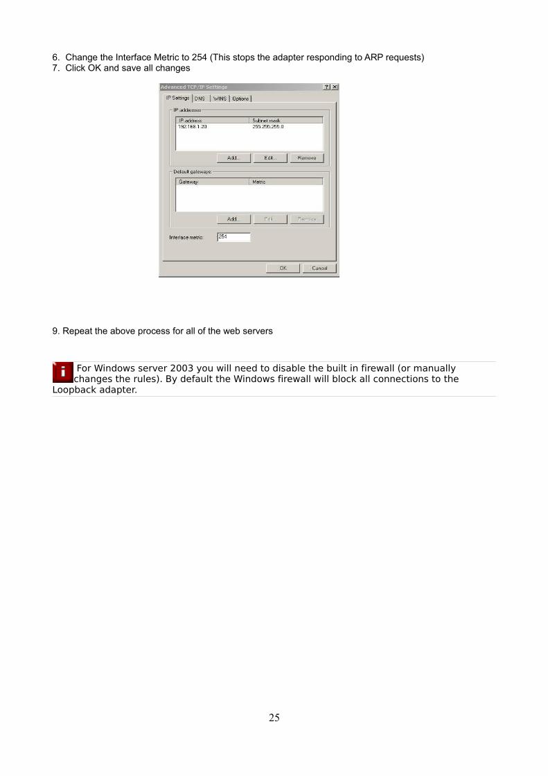
6. Change the Interface Metric to 254 (This stops the adapter responding to ARP requests)7. Click OK and save all changes
9. Repeat the above process for all of the web servers
For Windows server 2003 you will need to disable the built in firewall (or manually changes the rules). By default the Windows firewall will block all connections to the
Loopback adapter.
25
Resolving ARP issues for Windows server 2008 (DR mode only)
In Windows 2008 we have a whole new way of controlling networking. Microsoft finally have a sensible way of controlling network interfaces.
NB. Please read the previous section relating to MS loopback adapter installation.
For Windows Server 2008 you will need to disable the built in firewall (or manually change the rules). By default the Windows firewall will block all connections to the Loopback
adapter.
Weak and strong host behavior in Windows
Windows XP and Windows Server® 2003 use the weak host model for sending and receiving for all IPv4 interfaces and the strong host model for sending and receiving for all IPv6 interfaces. You cannot configure this behavior. The Next Generation TCP/IP stack in Windows Vista and Windows Server 2008 supports strong host sends and receives for both IPv4 and IPv6 by default.
• You still need to configure the loopback adapter with the VIP (but you don’t need to set the metric)
• You still need to disable the firewall (or enable traffic to and from the loopback)
• Then you need to use the following command line magic:
netsh interface ipv4 set interface "net" weakhostreceive=enabled netsh interface ipv4 set interface "Loopback" weakhostreceive=enabled netsh interface ipv4 set interface "Loopback" weakhostsend=enabled
26
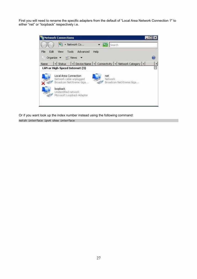
First you will need to rename the specific adapters from the default of “Local Area Network Connection 1″ to either “net” or “loopback” respectively i.e.
Or if you want look up the index number instead using the following command:
netsh interface ipv4 show interface
27
Testing the load balancer configuration
For testing add a page to each real web servers root directory i.e. test.html and put the server name on this page.
Now you need a couple of clients to do the testing. Open up a web browser on two different clients and enter the URL for the VIP i.e. http://192.168.1.20/
Each client should see a different server name because of the load balancing algorithm in use i.e. they are being load balanced across the cluster.
Why test two clients? If you use a single client it will most likely keep on hitting the same server for multiple requests. This is to do with the way that the load balancing algorithms are optimized.
When using a two-arm NAT load balancing method the test client must be in the external subnet.
Connection error diagnosis
If you get a connection error when trying to access the VIP then:
1. Check View Configuration > Network Configuration and make sure that the VIP is active on the load balancer, if not check Logs > Heartbeat for errors.
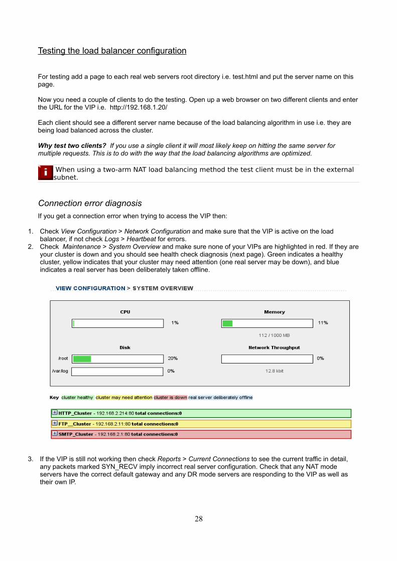
2. Check Maintenance > System Overview and make sure none of your VIPs are highlighted in red. If they are your cluster is down and you should see health check diagnosis (next page). Green indicates a healthy cluster, yellow indicates that your cluster may need attention (one real server may be down), and blue indicates a real server has been deliberately taken offline.
3. If the VIP is still not working then check Reports > Current Connections to see the current traffic in detail, any packets marked SYN_RECV imply incorrect real server configuration. Check that any NAT mode servers have the correct default gateway and any DR mode servers are responding to the VIP as well as their own IP.
28

Health check diagnosis
Go to the Maintenance > Take a real server offline or online section of the web interface and check that when you take servers offline the connections are redirected to the rest of the cluster as expected.
The example below shows that the requested status of WebServer1 is online but the actual status is non-active. This implies that the real server has failed a health check; you can investigate this using Logs > Ldirectord. If you know the real server should be active, you may need to increase the health check time-out Edit Configuration > Global Settings.
Pull the network cable out of one of the web servers, wait a few seconds (for the load balancer to detect the change) and then refresh the browsers on both clients. They should now both switch to the same server (as one has been removed from the load balancing list).
Put the network cable back in to the web server, wait a few seconds and then refresh the browsers again. They should now show different web servers again.
Testing high-availability for a Loadbalancer.org HA-pair
To test fail-over of a clustered pair of load balancers make sure that you power down the master and check that the slave unit takes over all the floating IP(s).
When testing load balancer fail-over, do not just pull the serial cable and network cable out. These will not cause a fail-over and will invalidate the cluster configuration (split
brain).You can configure fail-over on network failure but it is not enabled by default.
If fail-over does not occur correctly check Logs > Heartbeat on both nodes for any errors.
29
Does your application cluster correctly handle its own state?
Load balancers work most effectively if the application servers are completely stateless.This means that if a web server fails and is automatically taken out of the cluster; then all
the current user sessions will be transferred to other servers in the cluster without the users needing to re-login to the application again. If your application doesn't have a persistent data store then you can't have seamless fail over for your back end servers.
Web based applications are inherently stateless and an ideal candidate for load balancing:However, Do your web servers store persistent information on local drives?
• Images (jpeg, png, gif etc.)
• Files (html, php, asp etc.)If so these files either need to be on shared storage such as an NFS/CIFS mount, or they need to be replicated to all of the nodes in the cluster.
Replication solutions for shared data:
On UNIX you can use the RSYNC command to replicate files, on Windows Server you can use RSYNC as well but you may prefer ROBOCOPY from the Windows Server Resource Kit. Usually you will upload your content to one master server and then replicate it to the other servers in the cluster.
Solutions for session data:
Standard ASP and PHP session data is stored locally by default, leaving your session data in a local store will prevent you from implementing seamless application server fail over in your cluster. If an application server fails all of the local session data will be lost and your user will need to re-log in and possibly lose shopping baskets etc.
This problem is easily resolvable by implementing a shared persistent data store for the cluster. This is usually either done with a shared back end database or a shared memory solution.
30
What do you do if your application is not stateless?
Some applications require state to be maintained such as:
• Terminal Server
• SSH
• FTP (upload)
• SMTP (incoming)You may also find that you are unable to modify your HTTP/HTTPS based application to handle shared session data.
If this is the case you can use persistence by source IP address. You lose the ability to have transparent fail over, but you do still get increased capacity and manageability. This persistence problem occurs with all load balancers and all vendors use standard methods and technology to mitigate the issue.
Loadbalancer.org persistence methods
• Source IP (subnet)
• Cookie (Active or Passive)
The standard Layer 4 persistence method is source IP persistence, you can handle millions of persistent connections at Layer 4. Just modify your virtual server to be persistent if you require source IP persistence.
Cookies are a Layer 7 based persistence method that can offer more even traffic distribution and also handle any clients where the source IP address may change during the session (e.g. mega proxies).
NB. Cookies can only be used in HTTP/HTTPS based applications (see administration manual example 3).
Loadbalancer.org technical support
If you have any questions regarding the appliance don't hesitate to contact the support team [email protected] or your local reseller.
Loadbalancer.org hardware support
Hardware support can be arranged either direct with Loadbalancer.org or via your local reseller or through our support team.
For more detailed explanations and complex configurations please see our full administration manual:
http://www.loadbalancer.org/pdffiles/loadbalanceradministration.pdf
31
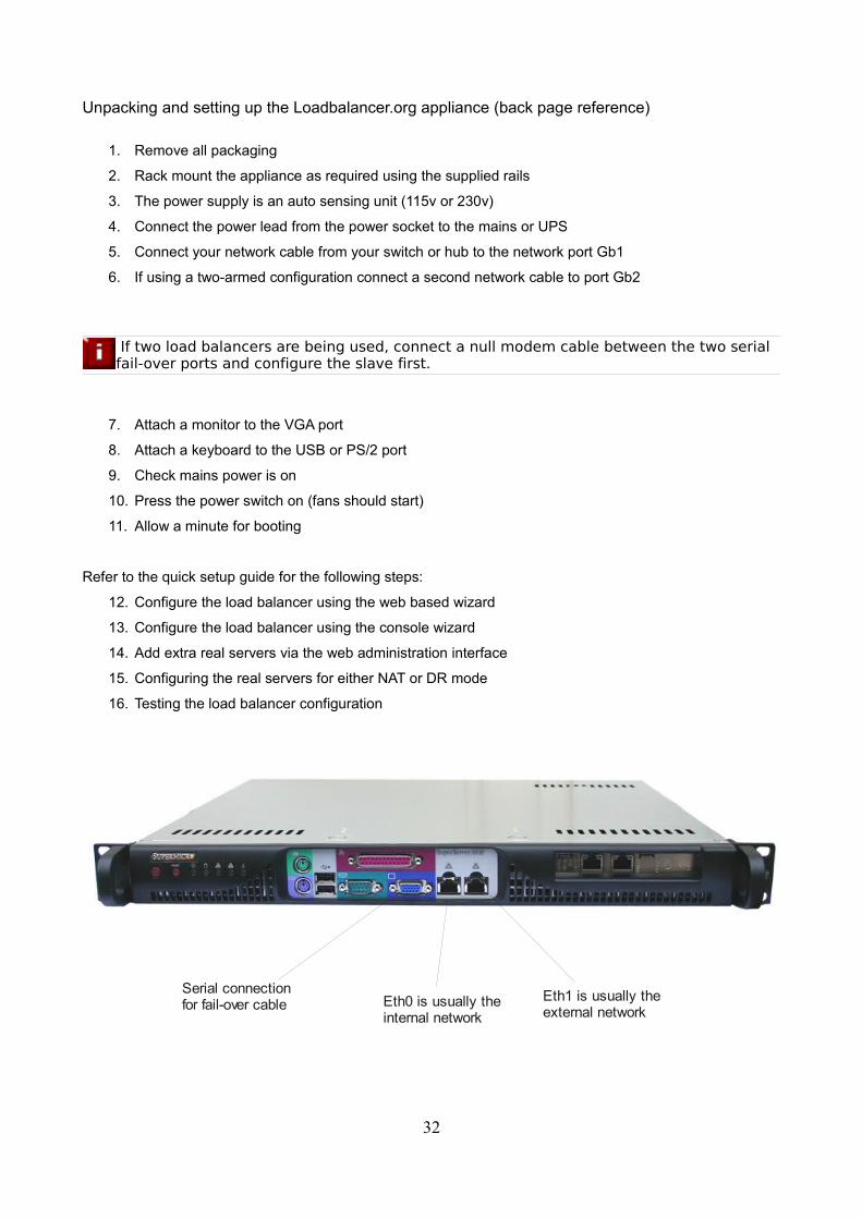
Unpacking and setting up the Loadbalancer.org appliance (back page reference)
1. Remove all packaging
2. Rack mount the appliance as required using the supplied rails
3. The power supply is an auto sensing unit (115v or 230v)
4. Connect the power lead from the power socket to the mains or UPS
5. Connect your network cable from your switch or hub to the network port Gb1
6. If using a two-armed configuration connect a second network cable to port Gb2
If two load balancers are being used, connect a null modem cable between the two serial fail-over ports and configure the slave first.
7. Attach a monitor to the VGA port
8. Attach a keyboard to the USB or PS/2 port
9. Check mains power is on
10. Press the power switch on (fans should start)
11. Allow a minute for booting
Refer to the quick setup guide for the following steps:
12. Configure the load balancer using the web based wizard
13. Configure the load balancer using the console wizard
14. Add extra real servers via the web administration interface
15. Configuring the real servers for either NAT or DR mode
16. Testing the load balancer configuration
32
Serial connection for fail-over cable Eth0 is usually the
internal network
Eth1 is usually the external network