Embed Size (px)
Citation preview

NetworX™ Series
NX-507E RELAY EXPANDER NX-508E OUTPUT EXPANDER
Installation and Startup

NX-507E / NX-508E AUXILIARY MODULES
3
TABLE OF CONTENTS
I. GENERAL DESCRIPTION ...............................................................................................4
II. WIRING INFORMATION ................................................................................................4
III. NX-507E TERMINAL DESCRIPTION .............................................................................5
IV. NX-507E DRAWING.......................................................................................................5
V. NX-508E TERMINAL DESCRIPTION .............................................................................6
VI. NX-508E DRAWING.......................................................................................................6
VII. INSTALLING THE MODULES.........................................................................................7
VIII. ENROLLING THE MODULES .........................................................................................7
IX. PROGRAMMING THE MODULES ..................................................................................7
X. PROGRAMMING LOCATIONS.......................................................................................8
XI. PROGRAMMING EXAMPLES .......................................................................................12
XII. PROGRAMMING WORKSHEETS .................................................................................13
XIII. ENCLOSURE DIAGRAM ...............................................................................................23
XIV. SPECIFICATIONS..........................................................................................................24
4 NX-507E / NX-508E AUXILIARY MODULES
I. GENERAL DESCRIPTION The NetworX NX-507E and NX-508E are auxiliary modules used to expand the capabilities of the NetworX control panels. While each unit has some unique features described in this section and also in the terminal descriptions, the basic installation and programming instructions are applicable to both modules. NX-507E SEVEN RELAY EXPANDER $ Microprocessor controlled 7-relay module $ Designed with 7 separate normally open and normally closed relay contacts for a variety of applications,
including access control, home control/automation, wireless interfaces, and security functions. Note: Access control and home automation have not been verified by UL testing.
$ Includes 1 low current trigger output (output 8) $ Up to 8 modules can be connected to the NetworX control panel $ Can be programmed to activate for an event in any or all partitions $ Each relay can be programmed to follow up to 8 different schedules to either activate the relay during the
“on” time, or used in conjunction with another programming option to create time zones $ Has an optional tamper switch and auxiliary power terminal (see terminal descriptions) making it ideal for
use in a remote location NX-508E EIGHT OUTPUT EXPANDER $ Microprocessor controlled 8-output module $ Equipped with 8 low current trigger outputs (see terminal drawing) $ Up to 8 modules can be added for a total output count of 64 $ Each output can be programmed to follow up to 8 different schedules to either activate the output during the
“on” time, or used in conjunction with another programming option to create time zones $ Has an optional tamper switch and auxiliary power terminal (refer to terminal descriptions on pages 5-6)
making it ideal for use in a remote location $ Has a built-in parallel interface for local printouts of all communicator activity $ THE NX-508E MODEL IS NOT LISTED FOR UL COMMERCIAL FIRE.
II. WIRING INFORMATION
For UL Commercial Fire systems, 18AWG wire shall be used. The NX-507E model shall be mounted in the control unit’s enclosure.
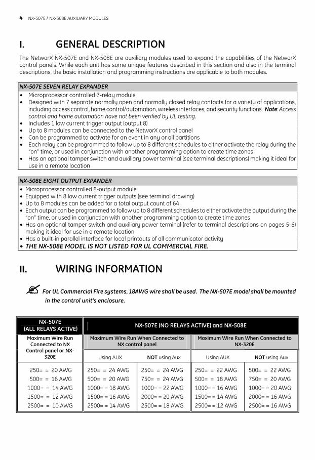
NX-507E
(ALL RELAYS ACTIVE) NX-507E (NO RELAYS ACTIVE) and NX-508E
Maximum Wire Run When Connected to NX control panel
Maximum Wire Run When Connected to NX-320E
Maximum Wire Run Connected to NX
Control panel or NX-320E
Using AUX
NOT using Aux
Using AUX
NOT using Aux
250= = 20 AWG 500= = 16 AWG 1000= = 14 AWG 1500= = 12 AWG 2500= = 10 AWG
250= = 24 AWG 500= = 20 AWG 1000= = 18 AWG 1500= = 16 AWG 2500= = 14 AWG
250= = 24 AWG 750= = 24 AWG 1000= = 22 AWG 2000= = 20 AWG 2500= = 18 AWG
250= = 22 AWG 500= = 18 AWG 1000= = 16 AWG 1500= = 14 AWG 2500= = 12 AWG
500= = 22 AWG 750= = 20 AWG 1000= = 20 AWG 2000= = 16 AWG 2500= = 16 AWG
NX-507E / NX-508E AUXILIARY MODULES
5
III. NX-507E TERMINAL DESCRIPTION DATA Connect to the control panel DATA terminal. This terminal is the data-signaling terminal to all the
devices on the buss.
COM Connect to the control panel COMMON terminal. This terminal supplies the common side of the power to the NX-507E board.
POS Connect to control panel AUX POWER + terminal. This terminal supplies power to the NX-507E board.
TAM This is an option tamper terminal. To use this feature, connect the normally closed tamper switch between this terminal and COM. If this feature is not used, a jumper must be connected between this terminal and common.
COM Connect to the tamper terminal through a normally closed contact. This terminal can supply up to 100 mA fused separate from the power in the control panel. AUX
Any power drain from this terminal should be included in total current draw from the NetworX control panel or NX-320E Power Supply as applicable. This allows an isolation of the power between the main control and remote devices. If a short is created past the AUX terminal, those devices will cease to function, but the other devices, including the NX-507E, will continue to operate. The NX-507E will report this problem to the control for display on the keypad as an expander power trouble.
7NC Normally closed dry contact rated 1 Amp at 30 Volts. 7COM Common dry contact rated 1 Amp at 30 VDC.
RELA
Y 7 7NO Normally open dry contact rated 1 Amp at 30 Volts.
RELAYS 1-6 Same as Relay 7 shown above.
OUTPUT 8 Open collector output that switches to GND when activated - capable of up to 100 mA. NOTE: If device is connected to output, it must see the transition from 13V to GND. Part # 8915 can be used to connect to Output 8.
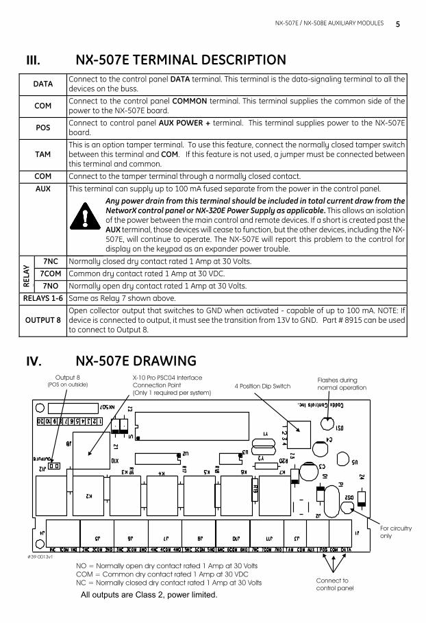
IV. NX-507E DRAWING
All outputs are Class 2, power limited.
6 NX-507E / NX-508E AUXILIARY MODULES
V. NX-508E TERMINAL DESCRIPTION DATA Connect to the control panel DATA terminal. This terminal is the data-signaling terminal to all the
devices on the buss.
COM Connect to the control panel COMMON terminal. This terminal supplies the common side of the power to the NX-508E board.
POS Connect to control panel AUX POWER + terminal. This terminal supplies power to the NX-508E board.
TAM This is an optional tamper terminal. To use this feature, connect the normally closed tamper switch between this terminal and COM. If this feature is not used, a jumper must be connected between this terminal and common.
COM Connect to the tamper terminal through a normally closed contact.
This terminal can supply up to 100 mA fused separate from the power in the control panel. AUX
Any power drain from this terminal should be included in total current draw from the NetworX control panel or NX-320E as applicable. This allows an isolation of the power between the main control and remote devices. If a short is created past the AUX terminal, those devices will cease to function, but the other devices, including the NX-508E, will continue to operate. The NX-508E will report this problem to the control for display on the keypad as an expander power trouble.
Out 1- 8 Open Collector outputs that switch to GND when activated -- capable of up to 100 mA. NOTE: If device is connected to outputs, it must see the transition from 13V to GND. The enclosed resistors must be used. Connect the resistor between AUX and the output being used.
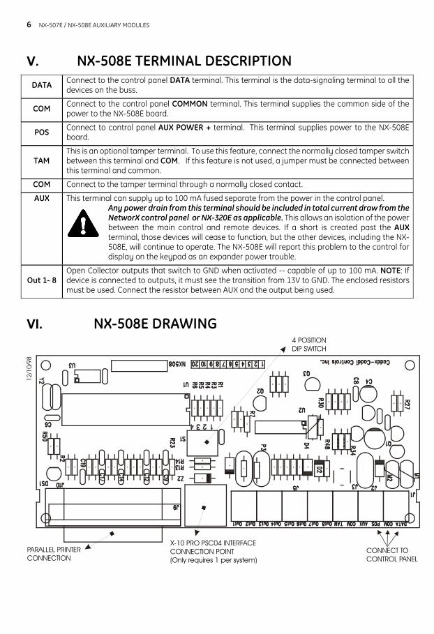
VI. NX-508E DRAWING 4 POSITIONDIP SWITCH
X-10 PRO PSC04 INTERFACECONNECTION POINT(Only requires 1 per system)
PARALLEL PRINTERCONNECTION
12/1
0/98
CONNECT TOCONTROL PANEL
NX-507E / NX-508E AUXILIARY MODULES
7
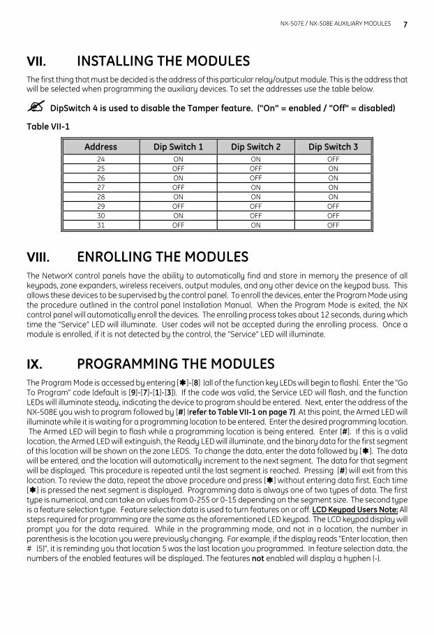
VII. INSTALLING THE MODULES The first thing that must be decided is the address of this particular relay/output module. This is the address that will be selected when programming the auxiliary devices. To set the addresses use the table below.
DipSwitch 4 is used to disable the Tamper feature. ("On" = enabled / "Off" = disabled)
Table VII-1
Address
Dip Switch 1
Dip Switch 2
Dip Switch 3 24 ON ON OFF 25 OFF OFF ON 26 ON OFF ON 27 OFF ON ON 28 ON ON ON 29 OFF OFF OFF 30 ON OFF OFF 31 OFF ON OFF
VIII. ENROLLING THE MODULES The NetworX control panels have the ability to automatically find and store in memory the presence of all keypads, zone expanders, wireless receivers, output modules, and any other device on the keypad buss. This allows these devices to be supervised by the control panel. To enroll the devices, enter the Program Mode using the procedure outlined in the control panel Installation Manual. When the Program Mode is exited, the NX control panel will automatically enroll the devices. The enrolling process takes about 12 seconds, during which time the “Service” LED will illuminate. User codes will not be accepted during the enrolling process. Once a module is enrolled, if it is not detected by the control, the “Service” LED will illuminate.
IX. PROGRAMMING THE MODULES The Program Mode is accessed by entering [ ]-[8] (all of the function key LEDs will begin to flash). Enter the "Go To Program" code (default is [9]-[7]-[1]-[3]). If the code was valid, the Service LED will flash, and the function LEDs will illuminate steady, indicating the device to program should be entered. Next, enter the address of the NX-508E you wish to program followed by [#] (refer to Table VII-1 on page 7). At this point, the Armed LED will illuminate while it is waiting for a programming location to be entered. Enter the desired programming location. The Armed LED will begin to flash while a programming location is being entered. Enter [#]. If this is a valid location, the Armed LED will extinguish, the Ready LED will illuminate, and the binary data for the first segment of this location will be shown on the zone LEDS. To change the data, enter the data followed by [ ]. The data will be entered, and the location will automatically increment to the next segment. The data for that segment will be displayed. This procedure is repeated until the last segment is reached. Pressing [#] will exit from this location. To review the data, repeat the above procedure and press [ ] without entering data first. Each time [ ] is pressed the next segment is displayed. Programming data is always one of two types of data. The first type is numerical, and can take on values from 0-255 or 0-15 depending on the segment size. The second type is a feature selection type. Feature selection data is used to turn features on or off. LCD Keypad Users Note: All steps required for programming are the same as the aforementioned LED keypad. The LCD keypad display will prompt you for the data required. While in the programming mode, and not in a location, the number in parenthesis is the location you were previously changing. For example, if the display reads "Enter location, then # (5)", it is reminding you that location 5 was the last location you programmed. In feature selection data, the numbers of the enabled features will be displayed. The features not enabled will display a hyphen (-).
8 NX-507E / NX-508E AUXILIARY MODULES
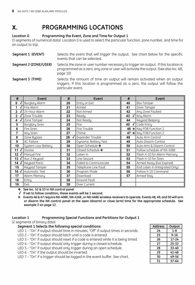
X. PROGRAMMING LOCATIONS Location 0 Programming the Event, Zone and Time for Output 1 (3 segments of numerical data) Location 0 is used to select the particular function, zone number, and time for an output to trip. Segment 1 (EVENT)
Selects the event that will trigger the output. See chart below for the specificevents that can be selected.
Segment 2 (ZONE/USER) Selects the zone or user number necessary to trigger an output. If this location isprogrammed as a zero, any zone or user will activate the output. (See also loc. 68,page 10)
Segment 3 (TIME) Selects the amount of time an output will remain activated when an outputtriggers. If this location is programmed as a zero, the output will follow theparticular event.
# Event # Event # Event 0 / Burglary Alarm 20 Entry or Exit 40 Box Tamper 1 / Fire Alarm 21 Armed 41 Siren Tamper 2 / 24 Hour Alarm 22 Not Armed 42 Any Zone Faulted 3 / Zone Trouble 23 Ready 43 / Any Alarm 4 / Zone Tamper 24 Not Ready 44 Keypad Beeping 5 Burglary Siren 25 Fire 45 / Code Entry 6 Fire Siren 26 Fire Trouble 46 : Key FOB Function 1 7 Any Siren 27 Chime 47 : Key FOB Function 2 8 Zone Bypass 28 / Expander Trouble 48 Auto Arm Control 9 AC Failure 29 Dynamic Battery Test 49 Auto Disarm Control
10 System Low Battery 30 Open Schedule ˜ 50 Auto Arm & Disarm Control 11 / Duress 31 Closed Schedule ˜ 51 Follow schedule of NX-508E 12 / Manual Fire 32 Listen In 52 Flash X-10 for Alarm Memory 13 / Aux 2 Keypad 33 Line Seizure 53 Flash X-10 for Siren 14 / Keypad Panic 34 Failed to Communicate 54 Armed Away (Exit Expired) 15 Keypad Tamper 35 Telephone Line Fault 55 End Listen In (Integrated Only) 16 / Automatic Test 36 Program Mode 56 Follow X-10 Command 17 Alarm Memory 37 Download 57 Armed Stay 18 Entry 38 Ground Fault 19 Exit 39 Over Current ˜ See loc. 52 & 53 in NX control panel / If set to follow condition, these events will be 1 second. : Events 46 & 47 require NX-408E, NX-416E, or NX-448E wireless receivers to operate. Events 48, 49, and 50 will arm
or disarm the NX control panel at the open (disarm) or close (arm) time for the appropriate schedule. See example 3 on page 12.
Location 1 Programming Special Functions and Partitions for Output 1 (2 segments of binary data)
Segment 1 Selects the following special conditions: LED 1 - "On" if output should time in minutes; "Off" if output times in seconds. LED 2 - "On" if output should latch until a code is entered. LED 3 - "On" if output should reset if a code is entered while it is being timed. LED 4 - "On" if output should only trigger during a closed schedule. LED 5 - "On" if output should only trigger during an open schedule. LED 6 - "On" if the output should be inverted. LED 7 - "On" if a trigger should be logged in the event buffer. See chart.
Address Output 24 1-8 25 9-16 26 17-24 27 25-32 28 33-40 29 41-48 30 49-56 31 57-64
NX-507E / NX-508E AUXILIARY MODULES
9
Segment 2 Selects the following partitions: LED 1 - "On" if the event should activate when it occurs in Partition 1. LED 2 - "On" if the event should activate when it occurs in Partition 2. LED 3 - "On" if the event should activate when it occurs in Partition 3. LED 4 - "On" if the event should activate when it occurs in Partition 4. LED 5 - "On" if the event should activate when it occurs in Partition 5. LED 6 - "On" if the event should activate when it occurs in Partition 6. LED 7 - "On" if the event should activate when it occurs in Partition 7. LED 8 - "On" if the event should activate when it occurs in Partition 8.
Location 2 Enabling the Schedules for Output 1 (1 segment of binary data) Location 2 is used to enable any or all of the eight (8) schedules. LED 1 corresponds to Schedule 1 (see locations 32-34, page 9) and LED 8 corresponds to Schedule 8 (see locations 53-55, page 10). This location can be used in conjunction with the Special Function location to create an output that will only activate during certain times and/or certain days.
LED 1 - "On" if the event should follow Schedule 1. LED 2 - "On" if the event should follow Schedule 2. LED 3 - "On" if the event should follow Schedule 3. LED 4 - "On" if the event should follow Schedule 4. LED 5 - "On" if the event should follow Schedule 5. LED 6 - "On" if the event should follow Schedule 6. LED 7 - "On" if the event should follow Schedule 7. LED 8 - "On" If the event should follow Schedule 8.
Location 3 Programming the X-10 Address for Output 1 (2 segments of numerical data)
Segment 1 Program a number from 0-15 to represent the corresponding X-10 Module Number from the following table.
Module
1
2
3
4
5
6
7
8
9
10
11
12
13
14
15
16
Seg 1
0
1
2
3
4
5
6
7
8
9
10
11
12
13
14
15
Segment 2 Program a number from 0-15 to represent the corresponding X-10 House code from the
following table.
X-10 ADDRESS CODES 0=A 4=E 8=I 12=M 1=B 5=F 9=J 13=N 2=C 6=G 10=K 14=O 3=D 7=H 11=L 15=P
Locations 4 - 31 Programming For Outputs 2- 8 Locations 4 - 31 are used to program the events, zones and times, as well as the special functions, partitions,
schedules and X-10 addresses for Outputs 2 - 8. Each output has four locations that are programmed with the same steps as Output 1 described previously. Refer to Output 1 for specific instructions (locations 0 - 3, pages 8-9). Also refer to the worksheets beginning on page 13.
Location 32 Programming the Opening Time for Schedule 1 (2 segments of numerical data)
Segment 1 Program the hour of the opening time in 24-hour format. (1:00 PM = 13) Segment 2 Program the minutes after the hour of the opening time for Schedule 1.
10 NX-507E / NX-508E AUXILIARY MODULES
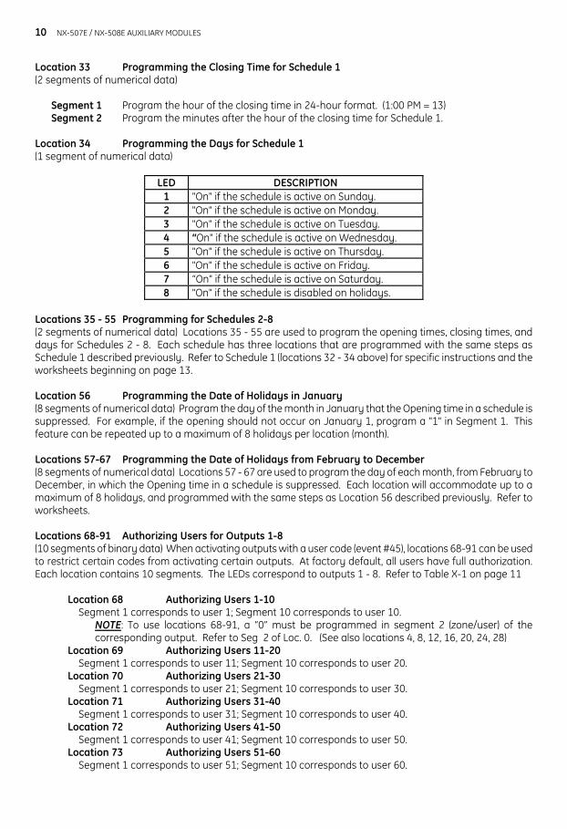
Location 33 Programming the Closing Time for Schedule 1 (2 segments of numerical data)
Segment 1 Program the hour of the closing time in 24-hour format. (1:00 PM = 13) Segment 2 Program the minutes after the hour of the closing time for Schedule 1.
Location 34 Programming the Days for Schedule 1 (1 segment of numerical data)
LED DESCRIPTION 1 "On" if the schedule is active on Sunday. 2 "On" if the schedule is active on Monday. 3 "On" if the schedule is active on Tuesday. 4 “On" if the schedule is active on Wednesday. 5 "On" if the schedule is active on Thursday. 6 "On" if the schedule is active on Friday. 7 “On" if the schedule is active on Saturday. 8 "On" if the schedule is disabled on holidays.
Locations 35 - 55 Programming for Schedules 2-8 (2 segments of numerical data) Locations 35 - 55 are used to program the opening times, closing times, and days for Schedules 2 - 8. Each schedule has three locations that are programmed with the same steps as Schedule 1 described previously. Refer to Schedule 1 (locations 32 - 34 above) for specific instructions and the worksheets beginning on page 13. Location 56 Programming the Date of Holidays in January (8 segments of numerical data) Program the day of the month in January that the Opening time in a schedule is suppressed. For example, if the opening should not occur on January 1, program a "1" in Segment 1. This feature can be repeated up to a maximum of 8 holidays per location (month). Locations 57-67 Programming the Date of Holidays from February to December (8 segments of numerical data) Locations 57 - 67 are used to program the day of each month, from February to December, in which the Opening time in a schedule is suppressed. Each location will accommodate up to a maximum of 8 holidays, and programmed with the same steps as Location 56 described previously. Refer to worksheets. Locations 68-91 Authorizing Users for Outputs 1-8 (10 segments of binary data) When activating outputs with a user code (event #45), locations 68-91 can be used to restrict certain codes from activating certain outputs. At factory default, all users have full authorization. Each location contains 10 segments. The LEDs correspond to outputs 1 - 8. Refer to Table X-1 on page 11
Location 68 Authorizing Users 1-10 Segment 1 corresponds to user 1; Segment 10 corresponds to user 10.
NOTE: To use locations 68-91, a “0” must be programmed in segment 2 (zone/user) of the corresponding output. Refer to Seg 2 of Loc. 0. (See also locations 4, 8, 12, 16, 20, 24, 28)
Location 69 Authorizing Users 11-20 Segment 1 corresponds to user 11; Segment 10 corresponds to user 20. Location 70 Authorizing Users 21-30 Segment 1 corresponds to user 21; Segment 10 corresponds to user 30. Location 71 Authorizing Users 31-40 Segment 1 corresponds to user 31; Segment 10 corresponds to user 40. Location 72 Authorizing Users 41-50 Segment 1 corresponds to user 41; Segment 10 corresponds to user 50. Location 73 Authorizing Users 51-60
Segment 1 corresponds to user 51; Segment 10 corresponds to user 60.
NX-507E / NX-508E AUXILIARY MODULES
11
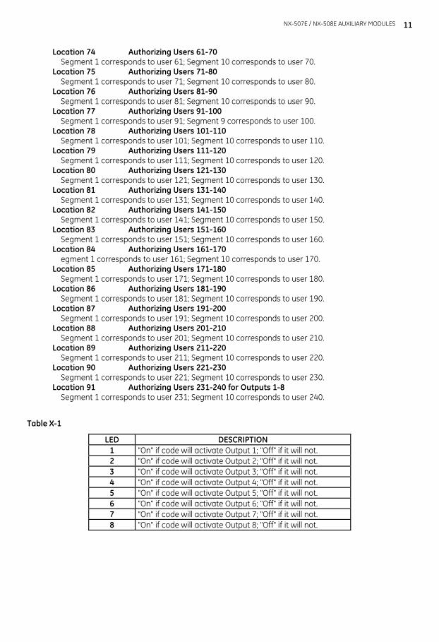
Location 74 Authorizing Users 61-70 Segment 1 corresponds to user 61; Segment 10 corresponds to user 70.
Location 75 Authorizing Users 71-80 Segment 1 corresponds to user 71; Segment 10 corresponds to user 80.
Location 76 Authorizing Users 81-90 Segment 1 corresponds to user 81; Segment 10 corresponds to user 90.
Location 77 Authorizing Users 91-100 Segment 1 corresponds to user 91; Segment 9 corresponds to user 100.
Location 78 Authorizing Users 101-110 Segment 1 corresponds to user 101; Segment 10 corresponds to user 110.
Location 79 Authorizing Users 111-120 Segment 1 corresponds to user 111; Segment 10 corresponds to user 120.
Location 80 Authorizing Users 121-130 Segment 1 corresponds to user 121; Segment 10 corresponds to user 130.
Location 81 Authorizing Users 131-140 Segment 1 corresponds to user 131; Segment 10 corresponds to user 140.
Location 82 Authorizing Users 141-150 Segment 1 corresponds to user 141; Segment 10 corresponds to user 150.
Location 83 Authorizing Users 151-160 Segment 1 corresponds to user 151; Segment 10 corresponds to user 160.
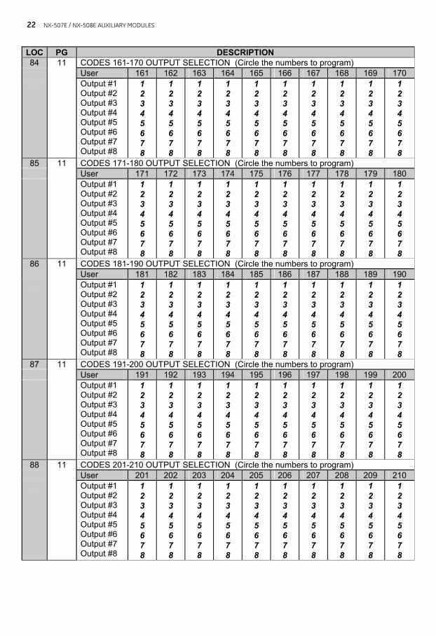
Location 84 Authorizing Users 161-170 egment 1 corresponds to user 161; Segment 10 corresponds to user 170.
Location 85 Authorizing Users 171-180 Segment 1 corresponds to user 171; Segment 10 corresponds to user 180.
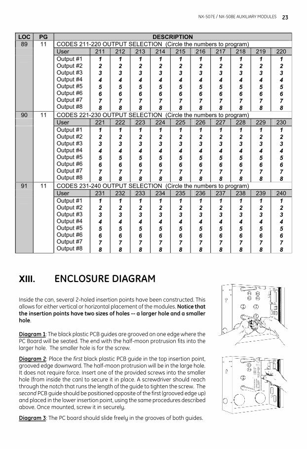
Location 86 Authorizing Users 181-190 Segment 1 corresponds to user 181; Segment 10 corresponds to user 190. Location 87 Authorizing Users 191-200 Segment 1 corresponds to user 191; Segment 10 corresponds to user 200. Location 88 Authorizing Users 201-210 Segment 1 corresponds to user 201; Segment 10 corresponds to user 210. Location 89 Authorizing Users 211-220 Segment 1 corresponds to user 211; Segment 10 corresponds to user 220. Location 90 Authorizing Users 221-230 Segment 1 corresponds to user 221; Segment 10 corresponds to user 230. Location 91 Authorizing Users 231-240 for Outputs 1-8 Segment 1 corresponds to user 231; Segment 10 corresponds to user 240.
Table X-1
LED DESCRIPTION 1 "On" if code will activate Output 1; "Off" if it will not. 2 "On" if code will activate Output 2; "Off" if it will not. 3 "On" if code will activate Output 3; "Off" if it will not. 4 "On" if code will activate Output 4; "Off" if it will not. 5 "On" if code will activate Output 5; "Off" if it will not. 6 "On" if code will activate Output 6; "Off" if it will not. 7 "On" if code will activate Output 7; "Off" if it will not. 8 "On" if code will activate Output 8; "Off" if it will not.
12 NX-507E / NX-508E AUXILIARY MODULES
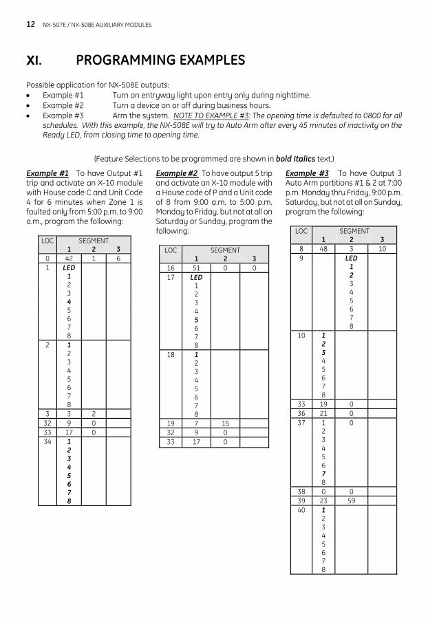
XI. PROGRAMMING EXAMPLES
Possible application for NX-508E outputs: • Example #1 Turn on entryway light upon entry only during nighttime. • Example #2 Turn a device on or off during business hours. • Example #3 Arm the system. NOTE TO EXAMPLE #3: The opening time is defaulted to 0800 for all
schedules. With this example, the NX-508E will try to Auto Arm after every 45 minutes of inactivity on the Ready LED, from closing time to opening time.
(Feature Selections to be programmed are shown in bold Italics text.)
Example #1 To have Output #1 trip and activate an X-10 module with House code C and Unit Code 4 for 6 minutes when Zone 1 is faulted only from 5:00 p.m. to 9:00 a.m., program the following:
SEGMENT LOC 1 2 3
0 42 1 6 1 LED
1 2 3 4 5 6 7 8
2 1 2 3 4 5 6 7 8
3 3 2 32 9 0 33 17 0 34 1
2 3 4 5 6 7 8
Example #2 To have output 5 trip and activate an X-10 module with a House code of P and a Unit code of 8 from 9:00 a.m. to 5:00 p.m. Monday to Friday, but not at all on Saturday or Sunday, program the following:
SEGMENT LOC 1 2 3
16 51 0 0 17 LED
1 2 3 4 5 6 7 8
18 1 2 3 4 5 6 7 8
19 7 15 32 9 0 33 17 0
Example #3 To have Output 3 Auto Arm partitions #1 & 2 at 7:00 p.m. Monday thru Friday, 9:00 p.m. Saturday, but not at all on Sunday, program the following:
SEGMENT LOC 1 2 3
8 48 3 10 9 LED
1 2 3 4 5 6 7 8
10 1 2 3 4 5 6 7 8
33 19 0 36 21 0 37 1
2 3 4 5 6 7 8
0
38 0 0 39 23 59 40 1
2 3 4 5 6 7 8
NX-507E / NX-508E AUXILIARY MODULES
13
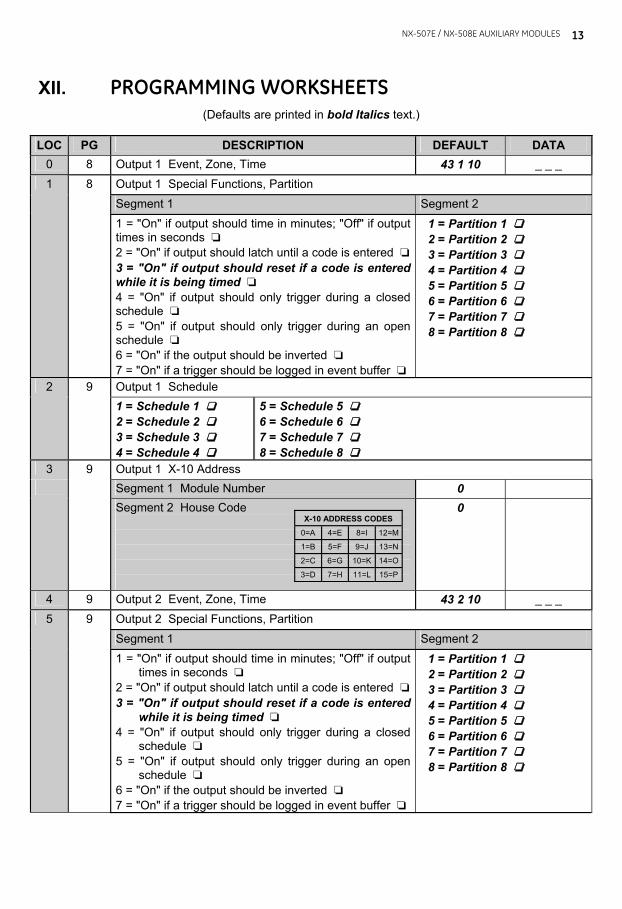
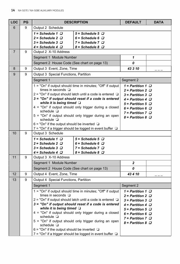
XII. PROGRAMMING WORKSHEETS (Defaults are printed in bold Italics text.)
LOC PG DESCRIPTION DEFAULT DATA
0 8 Output 1 Event, Zone, Time 43 1 10 _ _ _ Output 1 Special Functions, Partition Segment 1 Segment 2
1 8
1 = "On" if output should time in minutes; "Off" if output times in seconds ‘ 2 = "On" if output should latch until a code is entered ‘3 = "On" if output should reset if a code is entered while it is being timed ‘ 4 = "On" if output should only trigger during a closed schedule ‘ 5 = "On" if output should only trigger during an open schedule ‘ 6 = "On" if the output should be inverted ‘ 7 = "On" if a trigger should be logged in event buffer ‘
1 = Partition 1 ‘ 2 = Partition 2 ‘ 3 = Partition 3 ‘ 4 = Partition 4 ‘ 5 = Partition 5 ‘ 6 = Partition 6 ‘ 7 = Partition 7 ‘ 8 = Partition 8 ‘
Output 1 Schedule 2 9 1 = Schedule 1 ‘ 2 = Schedule 2 ‘ 3 = Schedule 3 ‘ 4 = Schedule 4 ‘
5 = Schedule 5 ‘ 6 = Schedule 6 ‘ 7 = Schedule 7 ‘ 8 = Schedule 8 ‘
3 Output 1 X-10 Address Segment 1 Module Number 0
9
Segment 2 House Code
0
4 9 Output 2 Event, Zone, Time 43 2 10 _ _ _ Output 2 Special Functions, Partition Segment 1 Segment 2
5 9
1 = "On" if output should time in minutes; "Off" if output times in seconds ‘
2 = "On" if output should latch until a code is entered ‘3 = "On" if output should reset if a code is entered
while it is being timed ‘ 4 = "On" if output should only trigger during a closed
schedule ‘ 5 = "On" if output should only trigger during an open
schedule ‘ 6 = "On" if the output should be inverted ‘ 7 = "On" if a trigger should be logged in event buffer ‘
1 = Partition 1 ‘ 2 = Partition 2 ‘ 3 = Partition 3 ‘ 4 = Partition 4 ‘ 5 = Partition 5 ‘ 6 = Partition 6 ‘ 7 = Partition 7 ‘ 8 = Partition 8 ‘
X-10 ADDRESS CODES 0=A
4=E
8=I
12=M
1=B
5=F
9=J
13=N
2=C
6=G
10=K
14=O
3=D
7=H
11=L
15=P
14 NX-507E / NX-508E AUXILIARY MODULES
LOC PG DESCRIPTION DEFAULT DATA Output 2 Schedule 6 9
1 = Schedule 1 ‘ 2 = Schedule 2 ‘ 3 = Schedule 3 ‘ 4 = Schedule 4 ‘
5 = Schedule 5 ‘ 6 = Schedule 6 ‘ 7 = Schedule 7 ‘ 8 = Schedule 8 ‘
Output 2 X-10 Address Segment 1 Module Number 1
7 9
Segment 2 House Code (See chart on page 13) 0 8 9 Output 3 Event, Zone, Time 43 3 10 _ _ _
Output 3 Special Functions, Partition Segment 1 Segment 2
9 9
1 = "On" if output should time in minutes; "Off" if output times in seconds ‘
2 = "On" if output should latch until a code is entered ‘3 = "On" if output should reset if a code is entered
while it is being timed ‘ 4 = "On" if output should only trigger during a closed
schedule ‘ 5 = "On" if output should only trigger during an open
schedule ‘ 6 = "On" if the output should be inverted ‘ 7 = "On" if a trigger should be logged in event buffer ‘
1 = Partition 1 ‘ 2 = Partition 2 ‘ 3 = Partition 3 ‘ 4 = Partition 4 ‘ 5 = Partition 5 ‘ 6 = Partition 6 ‘ 7 = Partition 7 ‘ 8 = Partition 8 ‘
Output 3 Schedule 10 9 1 = Schedule 1 ‘ 2 = Schedule 2 ‘ 3 = Schedule 3 ‘ 4 = Schedule 4 ‘
5 = Schedule 5 ‘ 6 = Schedule 6 ‘ 7 = Schedule 7 ‘ 8 = Schedule 8 ‘
Output 3 X-10 Address Segment 1 Module Number 2
11 9
Segment 2 House Code (See chart on page 13) 0 12 9 Output 4 Event, Zone, Time 43 4 10 _ _ _
Output 4 Special Functions, Partition Segment 1 Segment 2
13 9
1 = "On" if output should time in minutes; "Off" if output times in seconds ‘
2 = "On" if output should latch until a code is entered ‘3 = "On" if output should reset if a code is entered
while it is being timed ‘ 4 = "On" if output should only trigger during a closed
schedule ‘ 5 = "On" if output should only trigger during an open
schedule ‘ 6 = "On" if the output should be inverted ‘ 7 = "On" if a trigger should be logged in event buffer ‘
1 = Partition 1 ‘ 2 = Partition 2 ‘ 3 = Partition 3 ‘ 4 = Partition 4 ‘ 5 = Partition 5 ‘ 6 = Partition 6 ‘ 7 = Partition 7 ‘ 8 = Partition 8 ‘
NX-507E / NX-508E AUXILIARY MODULES
15
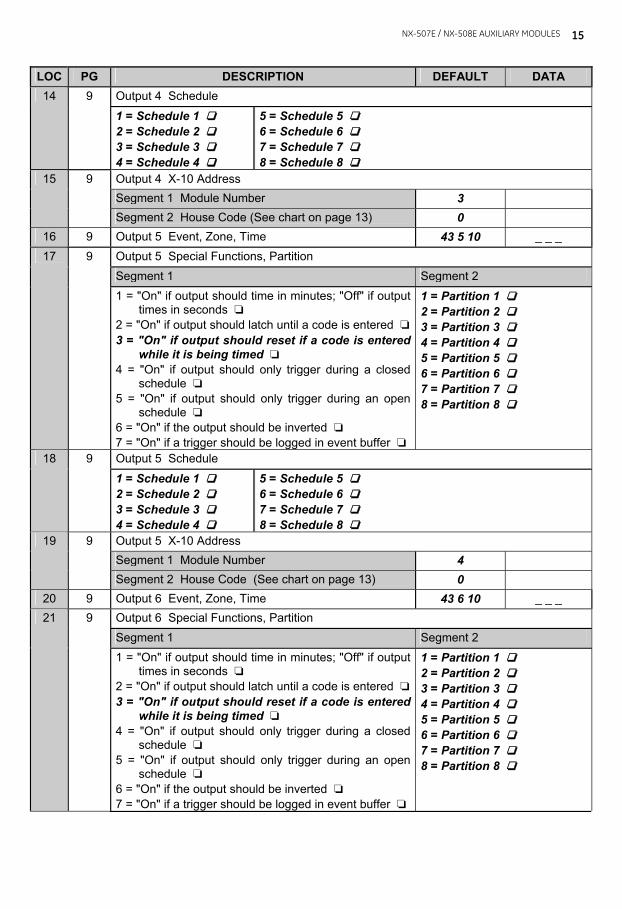
LOC PG DESCRIPTION DEFAULT DATA Output 4 Schedule 14 9 1 = Schedule 1 ‘ 2 = Schedule 2 ‘ 3 = Schedule 3 ‘ 4 = Schedule 4 ‘
5 = Schedule 5 ‘ 6 = Schedule 6 ‘ 7 = Schedule 7 ‘ 8 = Schedule 8 ‘
Output 4 X-10 Address Segment 1 Module Number 3
15 9
Segment 2 House Code (See chart on page 13) 0 16 9 Output 5 Event, Zone, Time 43 5 10 _ _ _
Output 5 Special Functions, Partition Segment 1 Segment 2
17 9
1 = "On" if output should time in minutes; "Off" if output times in seconds ‘
2 = "On" if output should latch until a code is entered ‘3 = "On" if output should reset if a code is entered
while it is being timed ‘ 4 = "On" if output should only trigger during a closed
schedule ‘ 5 = "On" if output should only trigger during an open
schedule ‘ 6 = "On" if the output should be inverted ‘ 7 = "On" if a trigger should be logged in event buffer ‘
1 = Partition 1 ‘ 2 = Partition 2 ‘ 3 = Partition 3 ‘ 4 = Partition 4 ‘ 5 = Partition 5 ‘ 6 = Partition 6 ‘ 7 = Partition 7 ‘ 8 = Partition 8 ‘
Output 5 Schedule 18 9 1 = Schedule 1 ‘ 2 = Schedule 2 ‘ 3 = Schedule 3 ‘ 4 = Schedule 4 ‘
5 = Schedule 5 ‘ 6 = Schedule 6 ‘ 7 = Schedule 7 ‘ 8 = Schedule 8 ‘
Output 5 X-10 Address Segment 1 Module Number 4
19 9
Segment 2 House Code (See chart on page 13) 0 20 9 Output 6 Event, Zone, Time 43 6 10 _ _ _
Output 6 Special Functions, Partition Segment 1 Segment 2
21 9
1 = "On" if output should time in minutes; "Off" if output times in seconds ‘
2 = "On" if output should latch until a code is entered ‘3 = "On" if output should reset if a code is entered
while it is being timed ‘ 4 = "On" if output should only trigger during a closed
schedule ‘ 5 = "On" if output should only trigger during an open
schedule ‘ 6 = "On" if the output should be inverted ‘ 7 = "On" if a trigger should be logged in event buffer ‘
1 = Partition 1 ‘ 2 = Partition 2 ‘ 3 = Partition 3 ‘ 4 = Partition 4 ‘ 5 = Partition 5 ‘ 6 = Partition 6 ‘ 7 = Partition 7 ‘ 8 = Partition 8 ‘
16 NX-507E / NX-508E AUXILIARY MODULES
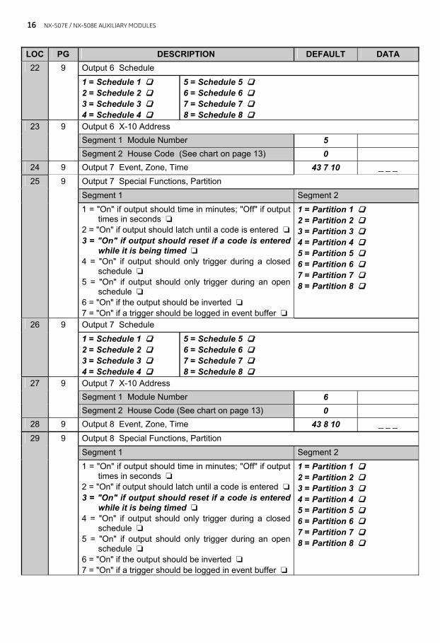
LOC PG DESCRIPTION DEFAULT DATA Output 6 Schedule 22 9 1 = Schedule 1 ‘ 2 = Schedule 2 ‘ 3 = Schedule 3 ‘ 4 = Schedule 4 ‘
5 = Schedule 5 ‘ 6 = Schedule 6 ‘ 7 = Schedule 7 ‘ 8 = Schedule 8 ‘
Output 6 X-10 Address Segment 1 Module Number 5
23 9
Segment 2 House Code (See chart on page 13) 0 24 9 Output 7 Event, Zone, Time 43 7 10 _ _ _
Output 7 Special Functions, Partition Segment 1 Segment 2
25 9
1 = "On" if output should time in minutes; "Off" if output times in seconds ‘
2 = "On" if output should latch until a code is entered ‘3 = "On" if output should reset if a code is entered
while it is being timed ‘ 4 = "On" if output should only trigger during a closed
schedule ‘ 5 = "On" if output should only trigger during an open
schedule ‘ 6 = "On" if the output should be inverted ‘ 7 = "On" if a trigger should be logged in event buffer ‘
1 = Partition 1 ‘ 2 = Partition 2 ‘ 3 = Partition 3 ‘ 4 = Partition 4 ‘ 5 = Partition 5 ‘ 6 = Partition 6 ‘ 7 = Partition 7 ‘ 8 = Partition 8 ‘
Output 7 Schedule 26 9 1 = Schedule 1 ‘ 2 = Schedule 2 ‘ 3 = Schedule 3 ‘ 4 = Schedule 4 ‘
5 = Schedule 5 ‘ 6 = Schedule 6 ‘ 7 = Schedule 7 ‘ 8 = Schedule 8 ‘
Output 7 X-10 Address Segment 1 Module Number 6
27 9
Segment 2 House Code (See chart on page 13) 0 28 9 Output 8 Event, Zone, Time 43 8 10 _ _ _
Output 8 Special Functions, Partition Segment 1 Segment 2
29 9
1 = "On" if output should time in minutes; "Off" if output times in seconds ‘
2 = "On" if output should latch until a code is entered ‘3 = "On" if output should reset if a code is entered
while it is being timed ‘ 4 = "On" if output should only trigger during a closed
schedule ‘ 5 = "On" if output should only trigger during an open
schedule ‘ 6 = "On" if the output should be inverted ‘ 7 = "On" if a trigger should be logged in event buffer ‘
1 = Partition 1 ‘ 2 = Partition 2 ‘ 3 = Partition 3 ‘ 4 = Partition 4 ‘ 5 = Partition 5 ‘ 6 = Partition 6 ‘ 7 = Partition 7 ‘ 8 = Partition 8 ‘
NX-507E / NX-508E AUXILIARY MODULES
17
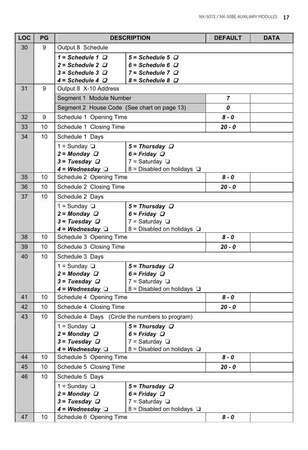
LOC PG DESCRIPTION DEFAULT DATA Output 8 Schedule 30 9 1 = Schedule 1 ‘ 2 = Schedule 2 ‘ 3 = Schedule 3 ‘ 4 = Schedule 4 ‘
5 = Schedule 5 ‘ 6 = Schedule 6 ‘ 7 = Schedule 7 ‘ 8 = Schedule 8 ‘
Output 8 X-10 Address Segment 1 Module Number 7
31 9
Segment 2 House Code (See chart on page 13) 0 32 9 Schedule 1 Opening Time 8 - 0 33 10 Schedule 1 Closing Time 20 - 0
10 Schedule 1 Days 34 1 = Sunday ‘
2 = Monday ‘ 3 = Tuesday ‘ 4 = Wednesday ‘
5 = Thursday ‘ 6 = Friday ‘ 7 = Saturday ‘ 8 = Disabled on holidays ‘
35 10 Schedule 2 Opening Time 8 - 0 36 10 Schedule 2 Closing Time 20 - 0
10 Schedule 2 Days 37 1 = Sunday ‘
2 = Monday ‘ 3 = Tuesday ‘ 4 = Wednesday ‘
5 = Thursday ‘ 6 = Friday ‘ 7 = Saturday ‘ 8 = Disabled on holidays ‘
38 10 Schedule 3 Opening Time 8 - 0 39 10 Schedule 3 Closing Time 20 - 0
Schedule 3 Days 40 10 1 = Sunday ‘ 2 = Monday ‘ 3 = Tuesday ‘ 4 = Wednesday ‘
5 = Thursday ‘ 6 = Friday ‘ 7 = Saturday ‘ 8 = Disabled on holidays ‘
41 10 Schedule 4 Opening Time 8 - 0 42 10 Schedule 4 Closing Time 20 - 0
Schedule 4 Days (Circle the numbers to program) 43 10 1 = Sunday ‘ 2 = Monday ‘ 3 = Tuesday ‘ 4 = Wednesday ‘
5 = Thursday ‘ 6 = Friday ‘ 7 = Saturday ‘ 8 = Disabled on holidays ‘
44 10 Schedule 5 Opening Time 8 - 0 45 10 Schedule 5 Closing Time 20 - 0
Schedule 5 Days 46 10 1 = Sunday ‘ 2 = Monday ‘ 3 = Tuesday ‘ 4 = Wednesday ‘
5 = Thursday ‘ 6 = Friday ‘ 7 = Saturday ‘ 8 = Disabled on holidays ‘
47 10 Schedule 6 Opening Time 8 - 0
18 NX-507E / NX-508E AUXILIARY MODULES
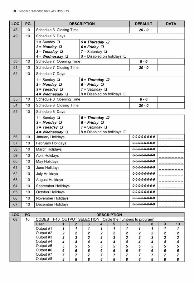
LOC PG DESCRIPTION DEFAULT DATA 48 10 Schedule 6 Closing Time 20 - 0
Schedule 6 Days 49 10 1 = Sunday ‘ 2 = Monday ‘ 3 = Tuesday ‘ 4 = Wednesday ‘
5 = Thursday ‘ 6 = Friday ‘ 7 = Saturday ‘ 8 = Disabled on holidays ‘
50 10 Schedule 7 Opening Time 8 - 0 51 10 Schedule 7 Closing Time 20 - 0
Schedule 7 Days 52 10 1 = Sunday ‘ 2 = Monday ‘ 3 = Tuesday ‘ 4 = Wednesday ‘
5 = Thursday ‘ 6 = Friday ‘ 7 = Saturday ‘ 8 = Disabled on holidays ‘
53 10 Schedule 8 Opening Time 8 - 0 54 10 Schedule 8 Closing Time 20 - 0
10 Schedule 8 Days 55
1 = Sunday ‘ 2 = Monday ‘ 3 = Tuesday ‘ 4 = Wednesday ‘
5 = Thursday ‘ 6 = Friday ‘ 7 = Saturday ‘ 8 = Disabled on holidays ‘
56 10 January Holidays 0-0-0-0-0-0-0-0 _ _ _ _ _ _ _ _ 57 10 February Holidays 0-0-0-0-0-0-0-0 _ _ _ _ _ _ _ _ 58 10 March Holidays 0-0-0-0-0-0-0-0 _ _ _ _ _ _ _ _ 59 10 April Holidays 0-0-0-0-0-0-0-0 _ _ _ _ _ _ _ _ 60 10 May Holidays 0-0-0-0-0-0-0-0 _ _ _ _ _ _ _ _ 61 10 June Holidays 0-0-0-0-0-0-0-0 _ _ _ _ _ _ _ _ 62 10 July Holidays 0-0-0-0-0-0-0-0 _ _ _ _ _ _ _ _ 63 10 August Holidays 0-0-0-0-0-0-0-0 _ _ _ _ _ _ _ _ 64 10 September Holidays 0-0-0-0-0-0-0-0 _ _ _ _ _ _ _ _ 65 10 October Holidays 0-0-0-0-0-0-0-0 _ _ _ _ _ _ _ _ 66 10 November Holidays 0-0-0-0-0-0-0-0 _ _ _ _ _ _ _ _ 67 10 December Holidays 0-0-0-0-0-0-0-0 _ _ _ _ _ _ _ _
LOC PG DESCRIPTION
CODES 1-10 OUTPUT SELECTION (Circle the numbers to program) User 1 2 3 4 5 6 7 8 9 10
68 10
Output #1 Output #2 Output #3 Output #4 Output #5 Output #6 Output #7 Output #8
1 2 3 4 5 6 7 8
1 2 3 4 5 6 7 8
1 2 3 4 5 6 7 8
1 2 3 4 5 6 7 8
1 2 3 4 5 6 7 8
1 2 3 4 5 6 7 8
1 2 3 4 5 6 7 8
1 2 3 4 5 6 7 8
1 2 3 4 5 6 7 8
1 2 3 4 5 6 7 8
NX-507E / NX-508E AUXILIARY MODULES
19
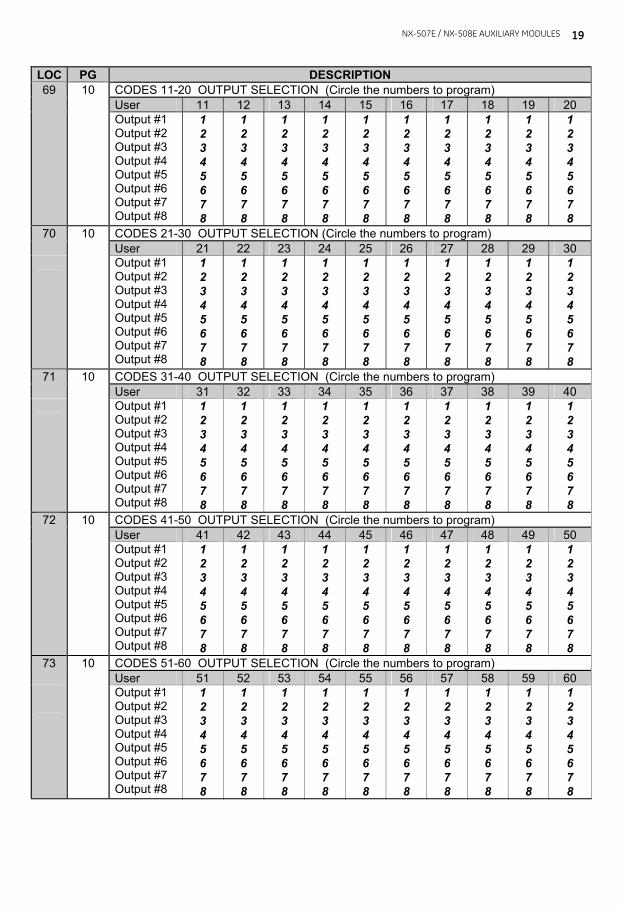
LOC PG DESCRIPTION CODES 11-20 OUTPUT SELECTION (Circle the numbers to program) 10 User 11 12 13 14 15 16 17 18 19 20
69
Output #1 Output #2 Output #3 Output #4 Output #5 Output #6 Output #7 Output #8
1 2 3 4 5 6 7 8
1 2 3 4 5 6 7 8
1 2 3 4 5 6 7 8
1 2 3 4 5 6 7 8
1 2 3 4 5 6 7 8
1 2 3 4 5 6 7 8
1 2 3 4 5 6 7 8
1 2 3 4 5 6 7 8
1 2 3 4 5 6 7 8
1 2 3 4 5 6 7 8
CODES 21-30 OUTPUT SELECTION (Circle the numbers to program) 70 10 User 21 22 23 24 25 26 27 28 29 30
Output #1 Output #2 Output #3 Output #4 Output #5 Output #6 Output #7 Output #8
1 2 3 4 5 6 7 8
1 2 3 4 5 6 7 8
1 2 3 4 5 6 7 8
1 2 3 4 5 6 7 8
1 2 3 4 5 6 7 8
1 2 3 4 5 6 7 8
1 2 3 4 5 6 7 8
1 2 3 4 5 6 7 8
1 2 3 4 5 6 7 8
1 2 3 4 5 6 7 8
CODES 31-40 OUTPUT SELECTION (Circle the numbers to program) 71 10 User 31 32 33 34 35 36 37 38 39 40
Output #1 Output #2 Output #3 Output #4 Output #5 Output #6 Output #7 Output #8
1 2 3 4 5 6 7 8
1 2 3 4 5 6 7 8
1 2 3 4 5 6 7 8
1 2 3 4 5 6 7 8
1 2 3 4 5 6 7 8
1 2 3 4 5 6 7 8
1 2 3 4 5 6 7 8
1 2 3 4 5 6 7 8
1 2 3 4 5 6 7 8
1 2 3 4 5 6 7 8
CODES 41-50 OUTPUT SELECTION (Circle the numbers to program) 10 User 41 42 43 44 45 46 47 48 49 50
72
Output #1 Output #2 Output #3 Output #4 Output #5 Output #6 Output #7 Output #8
1 2 3 4 5 6 7 8
1 2 3 4 5 6 7 8
1 2 3 4 5 6 7 8
1 2 3 4 5 6 7 8
1 2 3 4 5 6 7 8
1 2 3 4 5 6 7 8
1 2 3 4 5 6 7 8
1 2 3 4 5 6 7 8
1 2 3 4 5 6 7 8
1 2 3 4 5 6 7 8
CODES 51-60 OUTPUT SELECTION (Circle the numbers to program) 73 10 User 51 52 53 54 55 56 57 58 59 60
Output #1 Output #2 Output #3 Output #4 Output #5 Output #6 Output #7 Output #8
1 2 3 4 5 6 7 8
1 2 3 4 5 6 7 8
1 2 3 4 5 6 7 8
1 2 3 4 5 6 7 8
1 2 3 4 5 6 7 8
1 2 3 4 5 6 7 8
1 2 3 4 5 6 7 8
1 2 3 4 5 6 7 8
1 2 3 4 5 6 7 8
1 2 3 4 5 6 7 8
20 NX-507E / NX-508E AUXILIARY MODULES
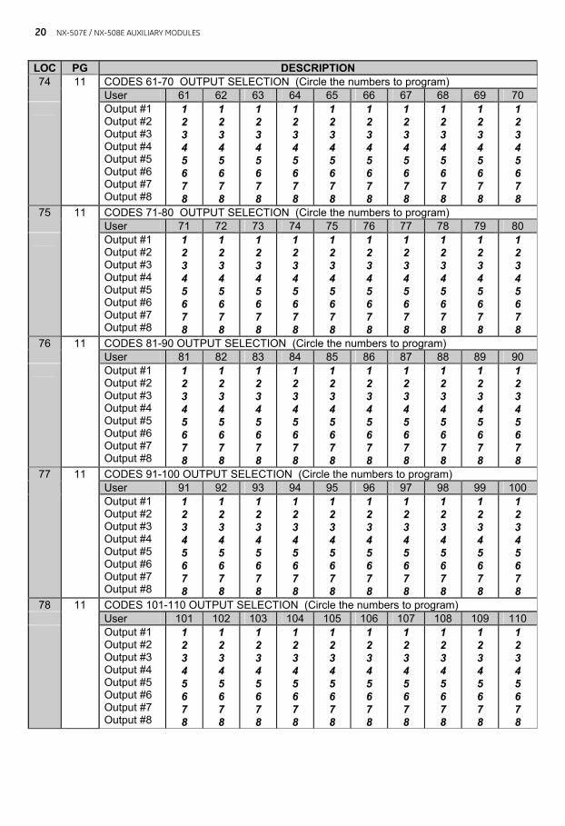
LOC PG DESCRIPTION CODES 61-70 OUTPUT SELECTION (Circle the numbers to program) 74 11 User 61 62 63 64 65 66 67 68 69 70
Output #1 Output #2 Output #3 Output #4 Output #5 Output #6 Output #7 Output #8
1 2 3 4 5 6 7 8
1 2 3 4 5 6 7 8
1 2 3 4 5 6 7 8
1 2 3 4 5 6 7 8
1 2 3 4 5 6 7 8
1 2 3 4 5 6 7 8
1 2 3 4 5 6 7 8
1 2 3 4 5 6 7 8
1 2 3 4 5 6 7 8
1 2 3 4 5 6 7 8
CODES 71-80 OUTPUT SELECTION (Circle the numbers to program) 75 11 User 71 72 73 74 75 76 77 78 79 80
Output #1 Output #2 Output #3 Output #4 Output #5 Output #6 Output #7 Output #8
1 2 3 4 5 6 7 8
1 2 3 4 5 6 7 8
1 2 3 4 5 6 7 8
1 2 3 4 5 6 7 8
1 2 3 4 5 6 7 8
1 2 3 4 5 6 7 8
1 2 3 4 5 6 7 8
1 2 3 4 5 6 7 8
1 2 3 4 5 6 7 8
1 2 3 4 5 6 7 8
CODES 81-90 OUTPUT SELECTION (Circle the numbers to program) 76 User 81 82 83 84 85 86 87 88 89 90
11
Output #1 Output #2 Output #3 Output #4 Output #5 Output #6 Output #7 Output #8
1 2 3 4 5 6 7 8
1 2 3 4 5 6 7 8
1 2 3 4 5 6 7 8
1 2 3 4 5 6 7 8
1 2 3 4 5 6 7 8
1 2 3 4 5 6 7 8
1 2 3 4 5 6 7 8
1 2 3 4 5 6 7 8
1 2 3 4 5 6 7 8
1 2 3 4 5 6 7 8
CODES 91-100 OUTPUT SELECTION (Circle the numbers to program) User 91 92 93 94 95 96 97 98 99 100
77 11
Output #1 Output #2 Output #3 Output #4 Output #5 Output #6 Output #7 Output #8
1 2 3 4 5 6 7 8
1 2 3 4 5 6 7 8
1 2 3 4 5 6 7 8
1 2 3 4 5 6 7 8
1 2 3 4 5 6 7 8
1 2 3 4 5 6 7 8
1 2 3 4 5 6 7 8
1 2 3 4 5 6 7 8
1 2 3 4 5 6 7 8
1 2 3 4 5 6 7 8
78 11 CODES 101-110 OUTPUT SELECTION (Circle the numbers to program) User 101 102 103 104 105 106 107 108 109 110 Output #1
Output #2 Output #3 Output #4 Output #5 Output #6 Output #7 Output #8
1 2 3 4 5 6 7 8
1 2 3 4 5 6 7 8
1 2 3 4 5 6 7 8
1 2 3 4 5 6 7 8
1 2 3 4 5 6 7 8
1 2 3 4 5 6 7 8
1 2 3 4 5 6 7 8
1 2 3 4 5 6 7 8
1 2 3 4 5 6 7 8
1 2 3 4 5 6 7 8
NX-507E / NX-508E AUXILIARY MODULES
21
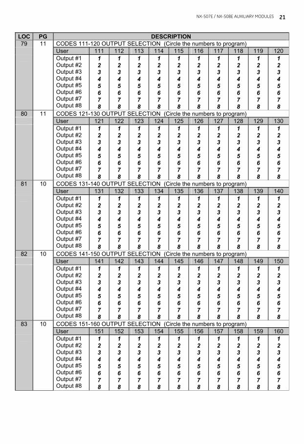
LOC PG DESCRIPTION 79 11 CODES 111-120 OUTPUT SELECTION (Circle the numbers to program) User 111 112 113 114 115 116 117 118 119 120 Output #1
Output #2 Output #3 Output #4 Output #5 Output #6 Output #7 Output #8
1 2 3 4 5 6 7 8
1 2 3 4 5 6 7 8
1 2 3 4 5 6 7 8
1 2 3 4 5 6 7 8
1 2 3 4 5 6 7 8
1 2 3 4 5 6 7 8
1 2 3 4 5 6 7 8
1 2 3 4 5 6 7 8
1 2 3 4 5 6 7 8
1 2 3 4 5 6 7 8
80 11 CODES 121-130 OUTPUT SELECTION (Circle the numbers to program) User 121 122 123 124 125 126 127 128 129 130 Output #1
Output #2 Output #3 Output #4 Output #5 Output #6 Output #7 Output #8
1 2 3 4 5 6 7 8
1 2 3 4 5 6 7 8
1 2 3 4 5 6 7 8
1 2 3 4 5 6 7 8
1 2 3 4 5 6 7 8
1 2 3 4 5 6 7 8
1 2 3 4 5 6 7 8
1 2 3 4 5 6 7 8
1 2 3 4 5 6 7 8
1 2 3 4 5 6 7 8
81 10 CODES 131-140 OUTPUT SELECTION (Circle the numbers to program) User 131 132 133 134 135 136 137 138 139 140 Output #1
Output #2 Output #3 Output #4 Output #5 Output #6 Output #7 Output #8
1 2 3 4 5 6 7 8
1 2 3 4 5 6 7 8
1 2 3 4 5 6 7 8
1 2 3 4 5 6 7 8
1 2 3 4 5 6 7 8
1 2 3 4 5 6 7 8
1 2 3 4 5 6 7 8
1 2 3 4 5 6 7 8
1 2 3 4 5 6 7 8
1 2 3 4 5 6 7 8
82 10 CODES 141-150 OUTPUT SELECTION (Circle the numbers to program) User 141 142 143 144 145 146 147 148 149 150 Output #1
Output #2 Output #3 Output #4 Output #5 Output #6 Output #7 Output #8
1 2 3 4 5 6 7 8
1 2 3 4 5 6 7 8
1 2 3 4 5 6 7 8
1 2 3 4 5 6 7 8
1 2 3 4 5 6 7 8
1 2 3 4 5 6 7 8
1 2 3 4 5 6 7 8
1 2 3 4 5 6 7 8
1 2 3 4 5 6 7 8
1 2 3 4 5 6 7 8
83 10 CODES 151-160 OUTPUT SELECTION (Circle the numbers to program) User 151 152 153 154 155 156 157 158 159 160 Output #1
Output #2 Output #3 Output #4 Output #5 Output #6 Output #7 Output #8
1 2 3 4 5 6 7 8
1 2 3 4 5 6 7 8
1 2 3 4 5 6 7 8
1 2 3 4 5 6 7 8
1 2 3 4 5 6 7 8
1 2 3 4 5 6 7 8
1 2 3 4 5 6 7 8
1 2 3 4 5 6 7 8
1 2 3 4 5 6 7 8
1 2 3 4 5 6 7 8
22 NX-507E / NX-508E AUXILIARY MODULES
LOC PG DESCRIPTION 84 11 CODES 161-170 OUTPUT SELECTION (Circle the numbers to program) User 161 162 163 164 165 166 167 168 169 170 Output #1
Output #2 Output #3 Output #4 Output #5 Output #6 Output #7 Output #8
1 2 3 4 5 6 7 8
1 2 3 4 5 6 7 8
1 2 3 4 5 6 7 8
1 2 3 4 5 6 7 8
1 2 3 4 5 6 7 8
1 2 3 4 5 6 7 8
1 2 3 4 5 6 7 8
1 2 3 4 5 6 7 8
1 2 3 4 5 6 7 8
1 2 3 4 5 6 7 8
85 11 CODES 171-180 OUTPUT SELECTION (Circle the numbers to program) User 171 172 173 174 175 176 177 178 179 180 Output #1
Output #2 Output #3 Output #4 Output #5 Output #6 Output #7 Output #8
1 2 3 4 5 6 7 8
1 2 3 4 5 6 7 8
1 2 3 4 5 6 7 8
1 2 3 4 5 6 7 8
1 2 3 4 5 6 7 8
1 2 3 4 5 6 7 8
1 2 3 4 5 6 7 8
1 2 3 4 5 6 7 8
1 2 3 4 5 6 7 8
1 2 3 4 5 6 7 8
86 11 CODES 181-190 OUTPUT SELECTION (Circle the numbers to program) User 181 182 183 184 185 186 187 188 189 190 Output #1
Output #2 Output #3 Output #4 Output #5 Output #6 Output #7 Output #8
1 2 3 4 5 6 7 8
1 2 3 4 5 6 7 8
1 2 3 4 5 6 7 8
1 2 3 4 5 6 7 8
1 2 3 4 5 6 7 8
1 2 3 4 5 6 7 8
1 2 3 4 5 6 7 8
1 2 3 4 5 6 7 8
1 2 3 4 5 6 7 8
1 2 3 4 5 6 7 8
87 11 CODES 191-200 OUTPUT SELECTION (Circle the numbers to program) User 191 192 193 194 195 196 197 198 199 200 Output #1
Output #2 Output #3 Output #4 Output #5 Output #6 Output #7 Output #8
1 2 3 4 5 6 7 8
1 2 3 4 5 6 7 8
1 2 3 4 5 6 7 8
1 2 3 4 5 6 7 8
1 2 3 4 5 6 7 8
1 2 3 4 5 6 7 8
1 2 3 4 5 6 7 8
1 2 3 4 5 6 7 8
1 2 3 4 5 6 7 8
1 2 3 4 5 6 7 8
88 11 CODES 201-210 OUTPUT SELECTION (Circle the numbers to program) User 201 202 203 204 205 206 207 208 209 210 Output #1
Output #2 Output #3 Output #4 Output #5 Output #6 Output #7 Output #8
1 2 3 4 5 6 7 8
1 2 3 4 5 6 7 8
1 2 3 4 5 6 7 8
1 2 3 4 5 6 7 8
1 2 3 4 5 6 7 8
1 2 3 4 5 6 7 8
1 2 3 4 5 6 7 8
1 2 3 4 5 6 7 8
1 2 3 4 5 6 7 8
1 2 3 4 5 6 7 8
NX-507E / NX-508E AUXILIARY MODULES
23
LOC PG DESCRIPTION 89 11 CODES 211-220 OUTPUT SELECTION (Circle the numbers to program) User 211 212 213 214 215 216 217 218 219 220 Output #1
Output #2 Output #3 Output #4 Output #5 Output #6 Output #7 Output #8
1 2 3 4 5 6 7 8
1 2 3 4 5 6 7 8
1 2 3 4 5 6 7 8
1 2 3 4 5 6 7 8
1 2 3 4 5 6 7 8
1 2 3 4 5 6 7 8
1 2 3 4 5 6 7 8
1 2 3 4 5 6 7 8
1 2 3 4 5 6 7 8
1 2 3 4 5 6 7 8
90 11 CODES 221-230 OUTPUT SELECTION (Circle the numbers to program) User 221 222 223 224 225 226 227 228 229 230 Output #1
Output #2 Output #3 Output #4 Output #5 Output #6 Output #7 Output #8
1 2 3 4 5 6 7 8
1 2 3 4 5 6 7 8
1 2 3 4 5 6 7 8
1 2 3 4 5 6 7 8
1 2 3 4 5 6 7 8
1 2 3 4 5 6 7 8
1 2 3 4 5 6 7 8
1 2 3 4 5 6 7 8
1 2 3 4 5 6 7 8
1 2 3 4 5 6 7 8
91 11 CODES 231-240 OUTPUT SELECTION (Circle the numbers to program) User 231 232 233 234 235 236 237 238 239 240 Output #1
Output #2 Output #3 Output #4 Output #5 Output #6 Output #7 Output #8
1 2 3 4 5 6 7 8
1 2 3 4 5 6 7 8
1 2 3 4 5 6 7 8
1 2 3 4 5 6 7 8
1 2 3 4 5 6 7 8
1 2 3 4 5 6 7 8
1 2 3 4 5 6 7 8
1 2 3 4 5 6 7 8
1 2 3 4 5 6 7 8
1 2 3 4 5 6 7 8
XIII. ENCLOSURE DIAGRAM Inside the can, several 2-holed insertion points have been constructed. This allows for either vertical or horizontal placement of the modules. Notice that the insertion points have two sizes of holes -- a larger hole and a smaller hole. Diagram 1: The black plastic PCB guides are grooved on one edge where the PC Board will be seated. The end with the half-moon protrusion fits into the larger hole. The smaller hole is for the screw.
Diagram 2: Place the first black plastic PCB guide in the top insertion point, grooved edge downward. The half-moon protrusion will be in the large hole. It does not require force. Insert one of the provided screws into the smaller hole (from inside the can) to secure it in place. A screwdriver should reach through the notch that runs the length of the guide to tighten the screw. The second PCB guide should be positioned opposite of the first (grooved edge up) and placed in the lower insertion point, using the same procedures described above. Once mounted, screw it in securely.
Diagram 3: The PC board should slide freely in the grooves of both guides.

24 NX-507E / NX-508E AUXILIARY MODULES
XIV. SPECIFICATIONS
DIMENSIONS 1 " Width x 6 " Length x 3 " Depth OPERATING POWER 12 VDC, Supplied from NX control panel or NX-320E AUXILIARY POWER Supplied by NX control panel or NX-320E Limited to 100 mA by NX-507E or NX-508E NX-507E CURRENT DRAW 10 mA with no relays active 310 mA with all relays active + current draw of any device attached NX-508E CURRENT DRAW 10 mA with no outputs active 25 mA with all outputs active + current draw of any device attached OPERATING TEMPERATURE 32 to 120 degrees F SHIPPING WEIGHT 1 lb.
COMPATIBLE NETWORX CONTROL PANELS:
NX-4 NX-6 NX-8 NX-8E NX-8-CF NX-8E-CF NX-4V2 NX-6V2 NX-8V2
UNDERWRITERS LABORATORIES LISTINGS: UL365 Police Station Connected Burglar Alarm Units & Systems NX-507E, NX-508E UL609 Local Burglar Alarm Units & Systems NX-507E, NX-508E UL864 Control Units for Fire-Protective Signaling Systems NX-507E only UL985 Household Fire Warning Systems NX-507E, NX-508E UL1023 Household Burglar Alarm Systems NX-507E, NX-508E UL1610 Central Station Burglar Alarm Units NX-507E, NX-508E UL1635 Digital Alarm Communication System Units NX-507E, NX-508E UL1637 Home Health Care Signaling Equipment NX-507E, NX-508E
Main 903-845-6941 Technical Support 888-437-3287 Main Fax 903-845-6811 Sales & Literature 800-547-2556 Web: www.gesecurity.com
NX507E-508EIH05 REV H (MAY 2005)


![NX post processor [NX CAM]](https://img.pdfslide.us/doc/110x75/588910c81a28ab4a5c8b59e9/nx-post-processor-nx-cam.jpg)