Embed Size (px)
Citation preview
Load Settlement System
Procedures and Methods
Effective January 2017
ATCO Electric i January 2017 Load Settlement System
TABLE OF CONTENTS
1. INTRODUCTION ....................................................................................................................... 1
2. SITE TO SETTLEMENT ZONE MAPPING .......................................................................... 2
3. LOAD PROFILING .................................................................................................................... 2
LOAD RESEARCH SAMPLES ............................................................................................................ 3 SAMPLING ACCURACY REQUIREMENTS ......................................................................................... 3 HISTORIC CLASS LOAD PROFILES .................................................................................................. 3 LOAD PROFILING METHOD ............................................................................................................ 4 MODELING ACCURACY REQUIREMENT .......................................................................................... 5 DEEMED LOAD PROFILES ............................................................................................................... 5 PROFILING CAP .............................................................................................................................. 6
4. DISTRIBUTION LOSSES AND UFE ....................................................................................... 7
HISTORIC LOSS STUDIES ................................................................................................................ 7 SERVICE LEVEL .............................................................................................................................. 7 CALCULATION OF TOTAL SYSTEM LOSSES..................................................................................... 8 ALLOCATION OF TOTAL SYSTEM LOSSES ....................................................................................... 9 UNACCOUNTED FOR ENERGY .......................................................................................................12
5. OTHER DISCRETIONARY MATTERS ................................................................................13
ESTIMATION OF CONSUMPTION AMOUNTS ....................................................................................13 DEEMED TIMES .............................................................................................................................13 IMPLEMENTATION ASSUMPTIONS ..................................................................................................13 POST FINAL ADJUSTMENT MECHANISM (PFAM) PROCESSING .....................................................13 CUMULATIVE METERING VALIDATION TEST PARAMETERS ..........................................................15
APPENDIX A – CALCULATION OF HOURLY ENERGY CONSUMPTION, LOSS AND UFE
.................................................................................................................................................16
CUMULATIVE METERED AND UNMETERED SITES .........................................................................16 INTERVAL METERED SITES ...........................................................................................................17
APPENDIX B – DEVELOPMENT OF THE SYSTEM LOSS EQUATION ..................................18

ATCO Electric 1 January 2017
Load Settlement System
1. INTRODUCTION
ATCO Electric’s Load Settlement System is designed to meet the 1
requirements of Alberta Utilities Commission (AUC) Rule 021 Settlement 2
System Code Rules (SSC). The SSC is a set of rules established by the AUC 3
under the authority of section 24.1(1) of the Electric Utilities Act. All Market 4
Participants as defined in the Electric Utilities Act are required to comply with 5
the SSC. 6
ATCO Electric has been allowed discretion in implementing some aspects of 7
the SSC. Under section 2.8 of the SSC, ATCO Electric, as Load Settlement 8
Agent (LSA), is responsible for making public on its website the procedures 9
and methods used to conduct settlement. The discretionary procedures and 10
methods implemented by ATCO Electric that impact load settlement 11
calculations are described in this document. 12
Two appendices are also included as part of this document. In Appendix A, a 13
method is provided for determining hourly customer site energy consumption, 14
loss and unaccounted for energy (UFE) from the SSC transaction set. 15
Appendix B provides background information with respect to the calculation of 16
the system loss equation parameters. 17
Questions with respect to ATCO Electric load settlement may be emailed to 18
ATCO Electric 2 January 2017
Load Settlement System
2. SITE TO SETTLEMENT ZONE MAPPING
Section 4.5 (2) of the SSC requires ATCO Electric as LSA to disclose 1
individual site to settlement zone mapping rules. ATCO Electric assigns 2
every site for which it is the LSA and all its service territory to a single 3
settlement zone. 4
3. LOAD PROFILING
Section 3.1 (1) of the SSC defines the acceptable methods for calculating 5
load profiles. 6
The ATCO Electric load settlement system uses only load research-based 7
profiles or deemed profiles. All customer sites which are not interval metered 8
are assigned a specific class load profile based on their distribution tariff rate 9
class. 10
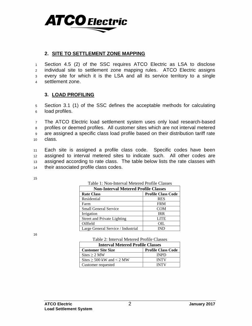
Each site is assigned a profile class code. Specific codes have been 11
assigned to interval metered sites to indicate such. All other codes are 12
assigned according to rate class. The table below lists the rate classes with 13
their associated profile class codes. 14
15
Table 1: Non-Interval Metered Profile Classes
Non-Interval Metered Profile Classes Rate Class Profile Class Code
Residential RES
Farm FRM
Small General Service COM
Irrigation IRR
Street and Private Lighting LITE
Oilfield OIL
Large General Service / Industrial IND
16
Table 2: Interval Metered Profile Classes
Interval Metered Profile Classes Customer Site Size Profile Class Code
Sites ≥ 2 MW INPD
Sites ≥ 500 kW and < 2 MW INTV
Customer requested INTV
ATCO Electric 3 January 2017
Load Settlement System
Section 3.2 (1) of the SSC requires ATCO Electric, as LSA, to state publicly 1
the existing rate classes for which separate load research-based profiles are 2
used in load settlement. The profiles for the residential, farm, small general 3
service and large general service/industrial rate classes are load research-4
based profiles. Deemed profiles are used for the oilfield, lighting and 5
irrigation classes. 6
The use of class specific load profiles for calculating monthly pool payments 7
ensures that the energy costs are allocated to each class as fairly as 8
possible. However, the cost of such an implementation needs to be balanced 9
against the degree for fairness achieved. The cost/benefit was maximized by 10
combining other load research needs with that of load settlement so as to 11
provide the same degree of fairness to the customer as they previously had. 12
Load Research Samples
Section 8 of the SSC defines the standards for load profiles based on load 13
research samples. For details on the requirements for estimation accuracy, 14
frame adequacy, and sample design and implementation please refer to 15
Section 8 of the SSC. 16
The class load profiles used by ATCO Electric for load settlement are based 17
on historic load surveys. ATCO Electric uses the method of stratified random 18
sampling for the selection of samples to represent each class. This method is 19
commonly used to ensure the most accurate results for a given sample size. 20
An annual load profile, for each class, is developed from the metered data 21
collected from the selected sample sites using the combined ratio estimation 22
technique. The value of the load profile, for each hour of the year, is the 23
energy (kW.h) used in that hour by the average customer site in the class. 24
Sampling Accuracy Requirements
Section 8.2.3 (2) of the SSC requires the design sampling variance Vcs to 25
meet the following criterion: 26
008.0 ccscs UVRSE 27
Historic Class Load Profiles
The historical profiles used in load settlement are posted on ATCO Electric’s 28
web site and can be accessed at 29
http://www.atcoelectric.com/B_retailers/resource_library.asp. 30

ATCO Electric 4 January 2017
Load Settlement System
Load Profiling Method
For load research-based profiles, ATCO Electric uses a profiling method 1
known as “proxy day” for estimating class load profiles. The proxy day 2
method compares the available characteristics of the settlement day to the 3
characteristics of historic days. The historic day that best matches the 4
settlement day is used as the proxy day. The historical class profile for that 5
day is then used as the class profile for the settlement day. This process is 6
repeated every day to produce a class load profile for the settlement period. 7
The proxy day method requires a library of class load profiles for historic days 8
as well as associated characteristics for selecting the proxy day. These 9
profiles are developed from the historic load studies described above. The 10
system load profile is a commonly used associated characteristic. The 11
system load profile (DSLS) is defined as the energy delivered to the 12
settlement zone less the energy delivered to all transmission-connected sites. 13
Other characteristics that may be used include day type, season, temperature 14
and time of the system peak. 15
The proxy day selection process used by ATCO Electric is provided by 16
ORACLE. ORACLE Utilities Load Profiling and Settlement (LPS) uses a two-17
step process to find a proxy day. The first step uses information about 18
settlement day to select a list of matching “eligible days”. The information 19
used to select the eligible days may include a combination of the following 20
characteristics: 21
Day type 22
Holiday 23
Season 24
System Peak Time 25
Ambient Temperature 26
These parameters may be varied for each profile class to ensure the eligible 27
days selected best represent the characteristics of the class. 28
Once a list of matching eligible days has been selected, the list is ranked by 29
comparing the system load profile for the settlement day to that of each 30
eligible day. Ranking may be done using a “magnitude” comparison or a 31
“shape” comparison. The two methods may also be combined by selecting a 32
weighting factor for each comparison and summing the weighted values. The 33
eligible day with the highest rank is then selected as the proxy day. 34
Once the proxy day selected, the date of the proxy day is used to select the 35
load profile for the class from the library of historic class load profiles. 36
ATCO Electric 5 January 2017
Load Settlement System
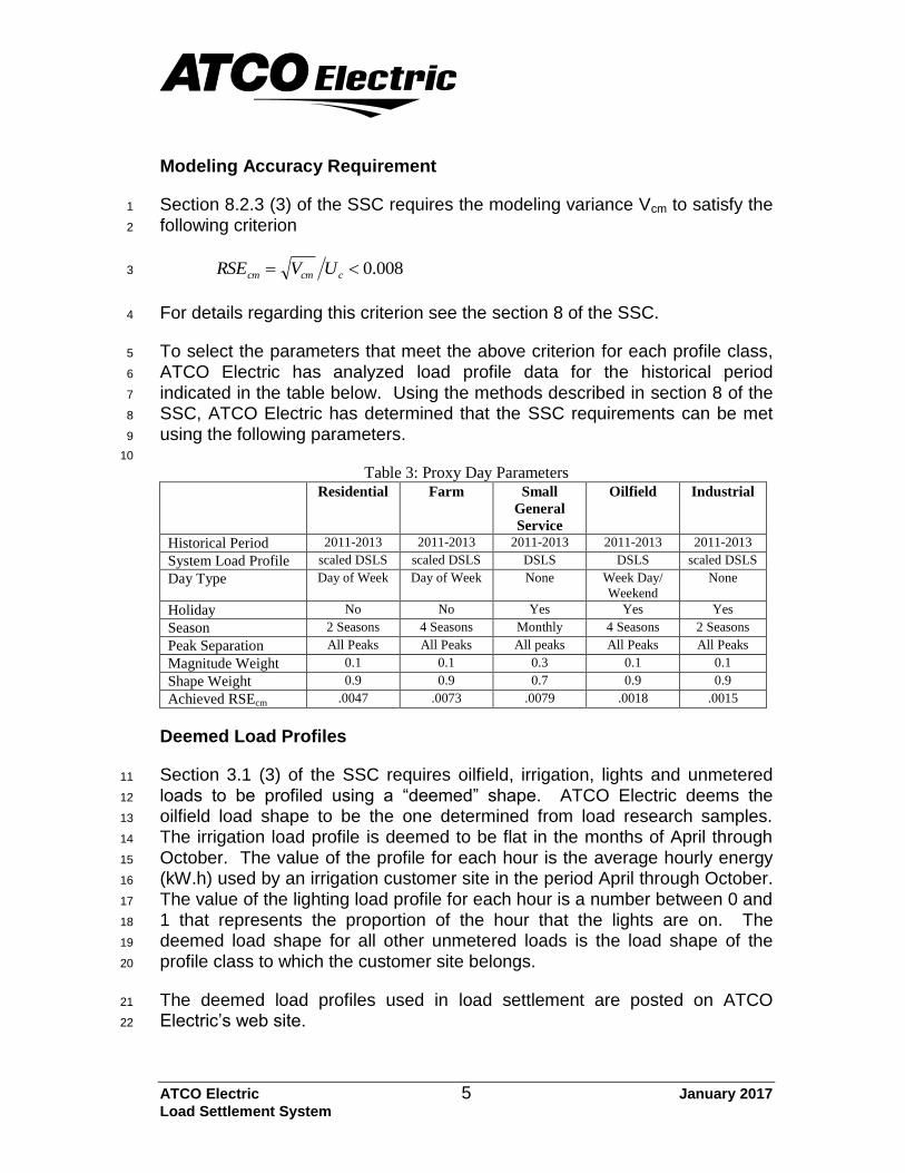
Modeling Accuracy Requirement
Section 8.2.3 (3) of the SSC requires the modeling variance Vcm to satisfy the 1
following criterion 2
008.0 ccmcm UVRSE 3
For details regarding this criterion see the section 8 of the SSC. 4
To select the parameters that meet the above criterion for each profile class, 5
ATCO Electric has analyzed load profile data for the historical period 6
indicated in the table below. Using the methods described in section 8 of the 7
SSC, ATCO Electric has determined that the SSC requirements can be met 8
using the following parameters. 9
10
Table 3: Proxy Day Parameters Residential Farm Small
General
Service
Oilfield Industrial
Historical Period 2011-2013 2011-2013 2011-2013 2011-2013 2011-2013
System Load Profile scaled DSLS scaled DSLS DSLS DSLS scaled DSLS
Day Type Day of Week Day of Week None Week Day/
Weekend
None
Holiday No No Yes Yes Yes
Season 2 Seasons 4 Seasons Monthly 4 Seasons 2 Seasons
Peak Separation All Peaks All Peaks All peaks All Peaks All Peaks
Magnitude Weight 0.1 0.1 0.3 0.1 0.1
Shape Weight 0.9 0.9 0.7 0.9 0.9
Achieved RSEcm .0047 .0073 .0079 .0018 .0015
Deemed Load Profiles
Section 3.1 (3) of the SSC requires oilfield, irrigation, lights and unmetered 11
loads to be profiled using a “deemed” shape. ATCO Electric deems the 12
oilfield load shape to be the one determined from load research samples. 13
The irrigation load profile is deemed to be flat in the months of April through 14
October. The value of the profile for each hour is the average hourly energy 15
(kW.h) used by an irrigation customer site in the period April through October. 16
The value of the lighting load profile for each hour is a number between 0 and 17
1 that represents the proportion of the hour that the lights are on. The 18
deemed load shape for all other unmetered loads is the load shape of the 19
profile class to which the customer site belongs. 20
The deemed load profiles used in load settlement are posted on ATCO 21
Electric’s web site. 22

ATCO Electric 6 January 2017
Load Settlement System
Profiling Cap
Section 3.3 (1) of the SSC requires a profiling cap of 2 MW or the WSP’s 1
current policy, whichever is lower. ATCO Electric’s profiling cap is 500 kW 2
consistent with currently approved rate schedules. Interval metered customer 3
sites that are below the profiling cap and are not a part of a profile class load 4
research sample will be settled according to their own interval data. 5

ATCO Electric 7 January 2017
Load Settlement System
4. DISTRIBUTION LOSSES AND UFE
Section 4.1 (2) of the SSC requires ATCO Electric, as a Wires Service 1
Provider (WSP), to provide 90 day notice prior to implementing changes to 2
load settlement loss calculations. This document describes the procedures 3
ATCO Electric will use to perform load settlement loss calculations on and 4
after the effective date of this document. Background information as to how 5
the parameters used in these procedures were derived is also provided. 6
Historic Loss Studies
Section 4.1 (1) of the SSC requires the WSPs that have been doing loss 7
calculations as part of cost-of-service studies to continue to use similar 8
methods to those they have been using. 9
The parameters used in the loss calculation procedures described below 10
come from two sources: previous load settlement calculations and distribution 11
loss studies of randomly selected distribution feeders. 12
Annual distribution losses were determined from total annual energy delivered 13
to the settlement zone less the total annual site energy consumption. The 14
source of this information is 2010 through 2014 load settlement results 15
adjusted for PFAMs applicable to the same period. The average annual 16
distribution system losses (4.75% of total annual site energy consumption) 17
calculated from these results form the basis for determining the required loss 18
calculation parameters. 19
The separation of total distribution losses into primary and secondary 20
distribution losses for each loss group is based on the results of studies 21
ATCO Electric conducted on randomly selected distribution feeder systems. 22
Information on feeder loading, configuration, physical characteristics and the 23
customer mix served from the feeders are used to determine the distribution 24
system losses for each loss group. 25
Service Level
For the purpose of performing loss calculations the ATCO Electric distribution 26
system has been separated into primary and secondary distribution systems. 27
Primary distribution consists of all 3-phase 25 kV lines. There are no 28
transformers in the primary distribution system. Secondary distribution 29
includes all elements of the distribution system that are not part of the primary 30
distribution system. 31
ATCO Electric 8 January 2017
Load Settlement System
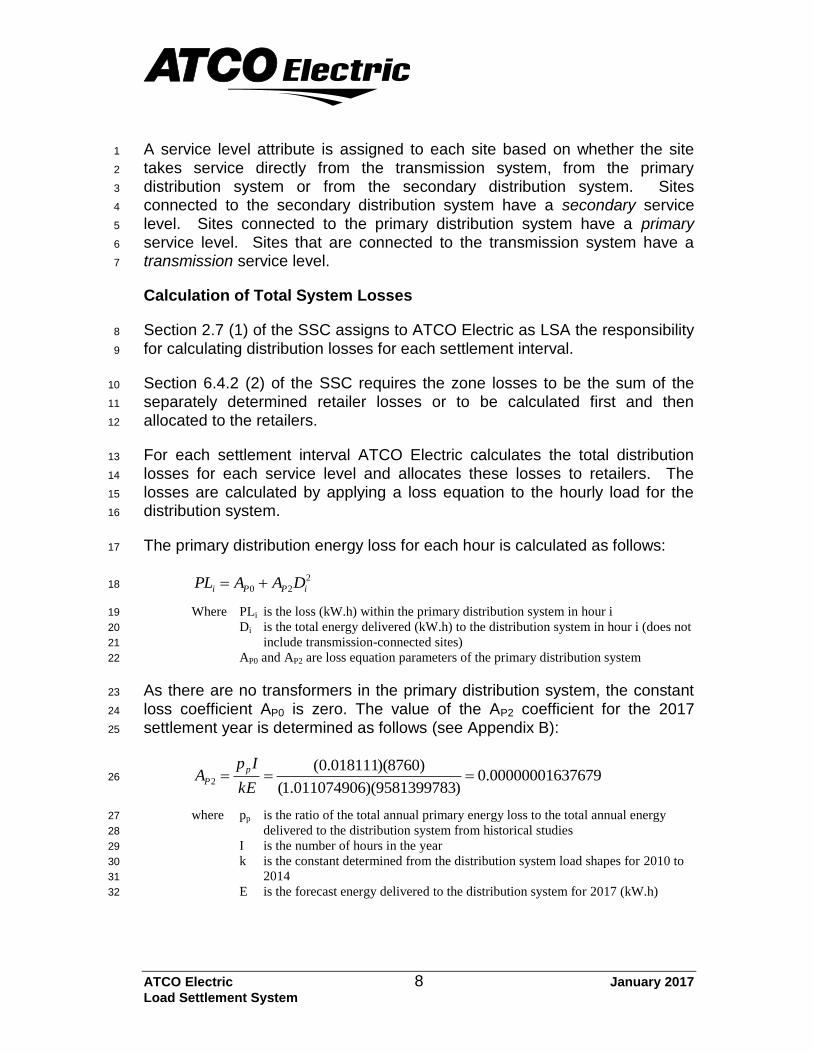
A service level attribute is assigned to each site based on whether the site 1
takes service directly from the transmission system, from the primary 2
distribution system or from the secondary distribution system. Sites 3
connected to the secondary distribution system have a secondary service 4
level. Sites connected to the primary distribution system have a primary 5
service level. Sites that are connected to the transmission system have a 6
transmission service level. 7
Calculation of Total System Losses
Section 2.7 (1) of the SSC assigns to ATCO Electric as LSA the responsibility 8
for calculating distribution losses for each settlement interval. 9
Section 6.4.2 (2) of the SSC requires the zone losses to be the sum of the 10
separately determined retailer losses or to be calculated first and then 11
allocated to the retailers. 12
For each settlement interval ATCO Electric calculates the total distribution 13
losses for each service level and allocates these losses to retailers. The 14
losses are calculated by applying a loss equation to the hourly load for the 15
distribution system. 16
The primary distribution energy loss for each hour is calculated as follows: 17
2
20 iPPi DAAPL 18
Where PLi is the loss (kW.h) within the primary distribution system in hour i 19
Di is the total energy delivered (kW.h) to the distribution system in hour i (does not 20
include transmission-connected sites) 21
AP0 and AP2 are loss equation parameters of the primary distribution system 22
As there are no transformers in the primary distribution system, the constant 23
loss coefficient AP0 is zero. The value of the AP2 coefficient for the 2017 24
settlement year is determined as follows (see Appendix B): 25
6376790.00000001)9581399783)(011074906.1(
)8760)(018111.0(2
kE
IpA
p
P 26
where pp is the ratio of the total annual primary energy loss to the total annual energy 27
delivered to the distribution system from historical studies 28
I is the number of hours in the year 29
k is the constant determined from the distribution system load shapes for 2010 to 30
2014 31
E is the forecast energy delivered to the distribution system for 2017 (kW.h) 32
ATCO Electric 9 January 2017
Load Settlement System
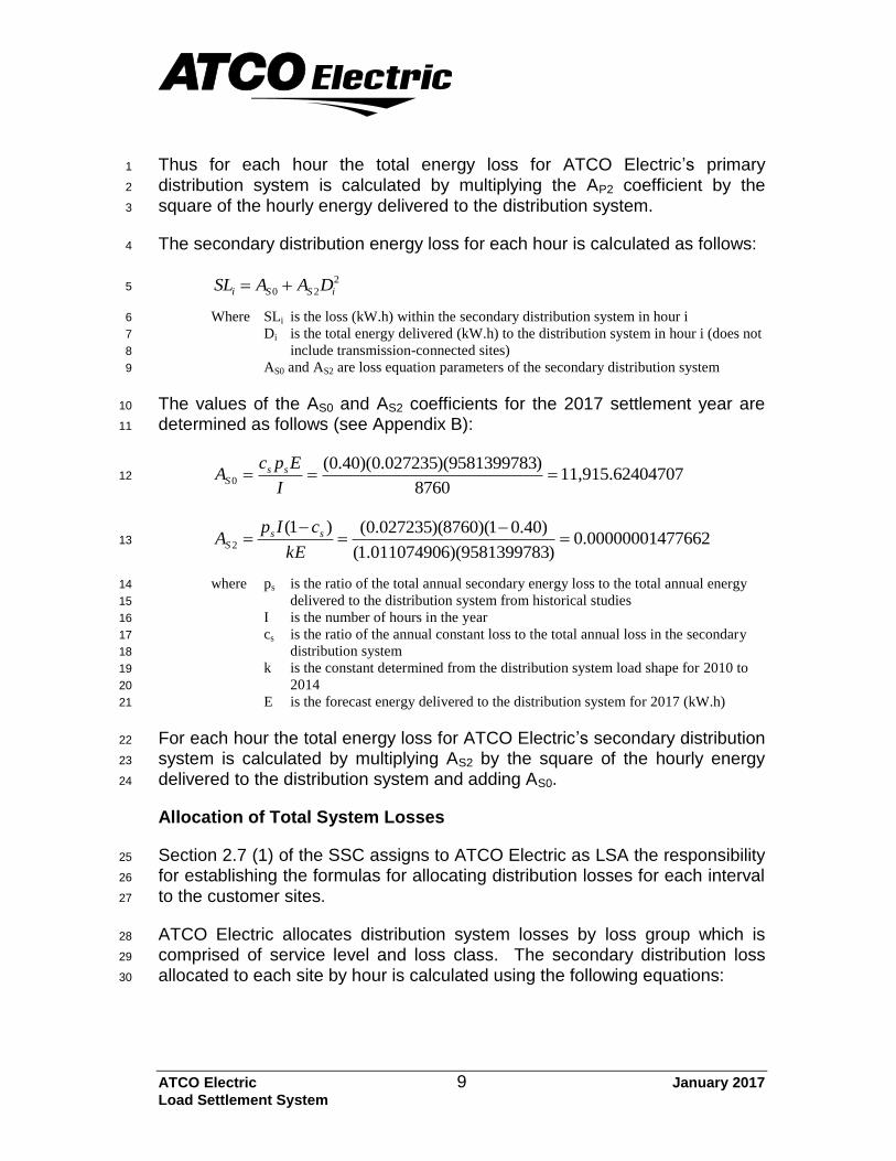
Thus for each hour the total energy loss for ATCO Electric’s primary 1
distribution system is calculated by multiplying the AP2 coefficient by the 2
square of the hourly energy delivered to the distribution system. 3
The secondary distribution energy loss for each hour is calculated as follows: 4
2
20 iSSi DAASL 5
Where SLi is the loss (kW.h) within the secondary distribution system in hour i 6
Di is the total energy delivered (kW.h) to the distribution system in hour i (does not 7
include transmission-connected sites) 8
AS0 and AS2 are loss equation parameters of the secondary distribution system 9
The values of the AS0 and AS2 coefficients for the 2017 settlement year are 10
determined as follows (see Appendix B): 11
0470711,915.6248760
)9581399783)(027235.0)(40.0(0
I
EpcA ss
S 12
4776620.00000001)9581399783)(61.01107490(
)40.01)(8760)(0.027235()1(2
kE
cIpA ss
S 13
where ps is the ratio of the total annual secondary energy loss to the total annual energy 14
delivered to the distribution system from historical studies 15
I is the number of hours in the year 16
cs is the ratio of the annual constant loss to the total annual loss in the secondary 17
distribution system 18
k is the constant determined from the distribution system load shape for 2010 to 19
2014 20
E is the forecast energy delivered to the distribution system for 2017 (kW.h) 21
For each hour the total energy loss for ATCO Electric’s secondary distribution 22
system is calculated by multiplying AS2 by the square of the hourly energy 23
delivered to the distribution system and adding AS0. 24
Allocation of Total System Losses
Section 2.7 (1) of the SSC assigns to ATCO Electric as LSA the responsibility 25
for establishing the formulas for allocating distribution losses for each interval 26
to the customer sites. 27
ATCO Electric allocates distribution system losses by loss group which is 28
comprised of service level and loss class. The secondary distribution loss 29
allocated to each site by hour is calculated using the following equations: 30
ATCO Electric 10 January 2017
Load Settlement System
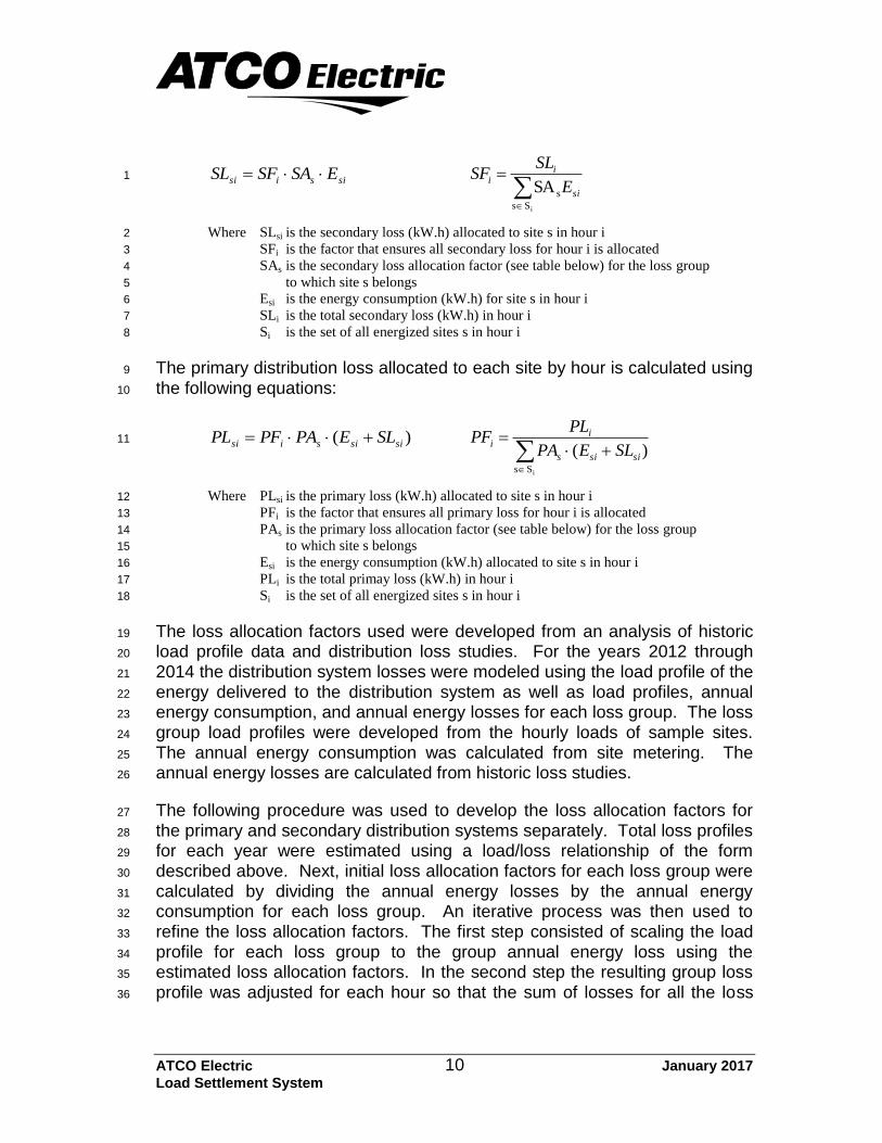
sisisi ESASFSL
iS s
sSA si
ii
E
SLSF 1
Where SLsi is the secondary loss (kW.h) allocated to site s in hour i 2
SFi is the factor that ensures all secondary loss for hour i is allocated 3
SAs is the secondary loss allocation factor (see table below) for the loss group 4
to which site s belongs 5
Esi is the energy consumption (kW.h) for site s in hour i 6
SLi is the total secondary loss (kW.h) in hour i 7
Si is the set of all energized sites s in hour i 8
The primary distribution loss allocated to each site by hour is calculated using 9
the following equations: 10
)( sisisisi SLEPAPFPL
iS s
)( sisis
ii
SLEPA
PLPF 11
Where PLsi is the primary loss (kW.h) allocated to site s in hour i 12
PFi is the factor that ensures all primary loss for hour i is allocated 13
PAs is the primary loss allocation factor (see table below) for the loss group 14
to which site s belongs 15
Esi is the energy consumption (kW.h) allocated to site s in hour i 16
PLi is the total primay loss (kW.h) in hour i 17
Si is the set of all energized sites s in hour i 18
The loss allocation factors used were developed from an analysis of historic 19
load profile data and distribution loss studies. For the years 2012 through 20
2014 the distribution system losses were modeled using the load profile of the 21
energy delivered to the distribution system as well as load profiles, annual 22
energy consumption, and annual energy losses for each loss group. The loss 23
group load profiles were developed from the hourly loads of sample sites. 24
The annual energy consumption was calculated from site metering. The 25
annual energy losses are calculated from historic loss studies. 26
The following procedure was used to develop the loss allocation factors for 27
the primary and secondary distribution systems separately. Total loss profiles 28
for each year were estimated using a load/loss relationship of the form 29
described above. Next, initial loss allocation factors for each loss group were 30
calculated by dividing the annual energy losses by the annual energy 31
consumption for each loss group. An iterative process was then used to 32
refine the loss allocation factors. The first step consisted of scaling the load 33
profile for each loss group to the group annual energy loss using the 34
estimated loss allocation factors. In the second step the resulting group loss 35
profile was adjusted for each hour so that the sum of losses for all the loss 36
ATCO Electric 11 January 2017
Load Settlement System
groups was equal to the total loss profile. Because this hourly adjustment 1
changed the shape of the group loss profiles the loss allocation factors were 2
readjusted. This iterative process was repeated and the loss allocation factors 3
refined until the difference between the total loss profile energy and the 4
annual energy loss for each loss group was less than 0.3%. 5
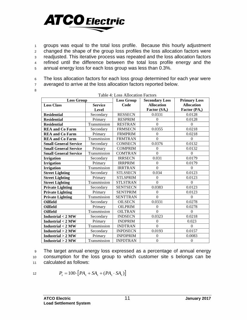
The loss allocation factors for each loss group determined for each year were 6
averaged to arrive at the loss allocation factors reported below. 7
8
Table 4: Loss Allocation Factors Loss Group Loss Group
Code
Secondary Loss
Allocation
Factor (SAs)
Primary Loss
Allocation
Factor (PAs) Loss Class Service
Level
Residential Secondary RESSECN 0.0331 0.0128
Residential Primary RESPRIM 0 0.0128
Residential Transmission RESTRAN 0 0
REA and Co Farm Secondary FRMSECN 0.0355 0.0218
REA and Co Farm Primary FRMPRIM 0 0.0218
REA and Co Farm Transmission FRMTRAN 0 0
Small General Service Secondary COMSECN 0.0376 0.0132
Small General Service Primary COMPRIM 0 0.0132
Small General Service Transmission COMTRAN 0 0
Irrigation Secondary IRRSECN 0.031 0.0179
Irrigation Primary IRRPRIM 0 0.0179
Irrigation Transmission IRRTRAN 0 0
Street Lighting Secondary STLSSECN 0.034 0.0123
Street Lighting Primary STLSPRIM 0 0.0123
Street Lighting Transmission STLSTRAN 0 0
Private Lighting Secondary SENTSECN 0.0383 0.0123
Private Lighting Primary SENTPRIM 0 0.0123
Private Lighting Transmission SENTTRAN 0 0
Oilfield Secondary OILSECN 0.0331 0.0278
Oilfield Primary OILPRIM 0 0.0278
Oilfield Transmission OILTRAN 0 0
Industrial < 2 MW Secondary INDSECN 0.0323 0.0218
Industrial < 2 MW Primary INDPRIM 0 0.023
Industrial < 2 MW Transmission INDTRAN 0 0
Industrial > 2 MW Secondary INPDSECN 0.0193 0.0157
Industrial > 2 MW Primary INPDPRIM 0 0.0083
Industrial > 2 MW Transmission INPDTRAN 0 0
The target annual energy loss expressed as a percentage of annual energy 9
consumption for the loss group to which customer site s belongs can be 10
calculated as follows: 11
)(100 sssss SAPASAPAP 12
ATCO Electric 12 January 2017
Load Settlement System
Where Ps is the percentage annual energy loss for the loss group to which site s belongs 1
PAs is the primary loss allocation factor for the loss group to which site s belongs 2
SAs is the secondary loss allocation factor for the loss group to which site s 3
belongs 4
Unaccounted For Energy
Section 4.2.1 of the SSC requires that the UFE calculated for each hour be 5
allocated to the customer sites of all retailers in proportion to their settled load 6
and allocated losses. Transmission-connected customer sites billed using the 7
same interval metered data as is used in the calculation of POD load are 8
exempt from this calculation. 9
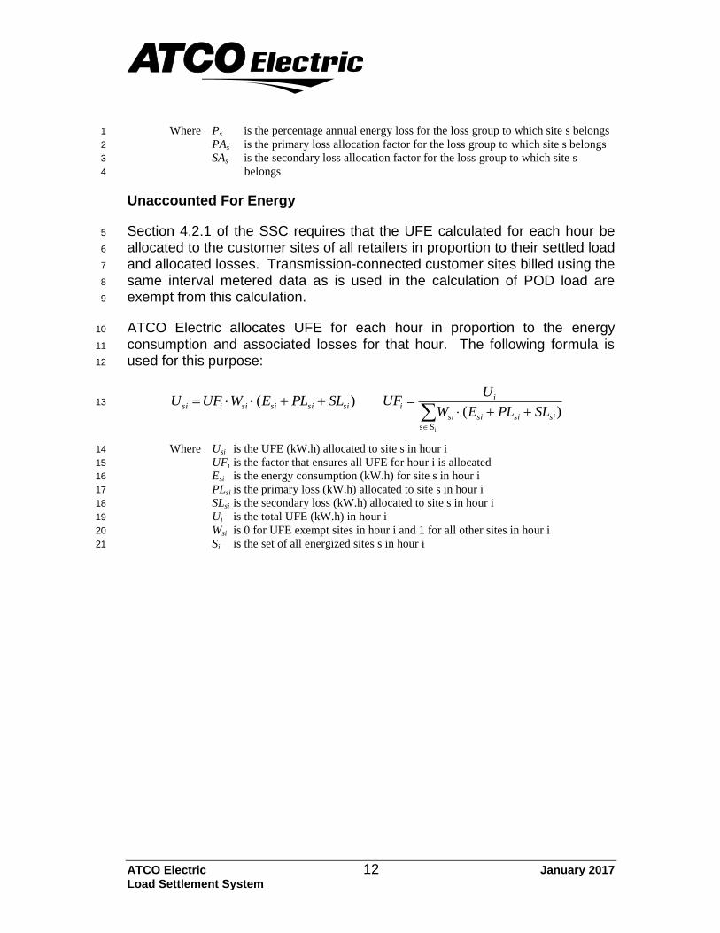
ATCO Electric allocates UFE for each hour in proportion to the energy 10
consumption and associated losses for that hour. The following formula is 11
used for this purpose: 12
)( sisisisiisi SLPLEWUFU
iS s
)( sisisisi
ii
SLPLEW
UUF 13
Where Usi is the UFE (kW.h) allocated to site s in hour i 14
UFi is the factor that ensures all UFE for hour i is allocated 15
Esi is the energy consumption (kW.h) for site s in hour i 16
PLsi is the primary loss (kW.h) allocated to site s in hour i 17
SLsi is the secondary loss (kW.h) allocated to site s in hour i 18
Ui is the total UFE (kW.h) in hour i 19
Wsi is 0 for UFE exempt sites in hour i and 1 for all other sites in hour i 20
Si is the set of all energized sites s in hour i 21
ATCO Electric 13 January 2017
Load Settlement System
5. OTHER DISCRETIONARY MATTERS
Estimation of Consumption Amounts
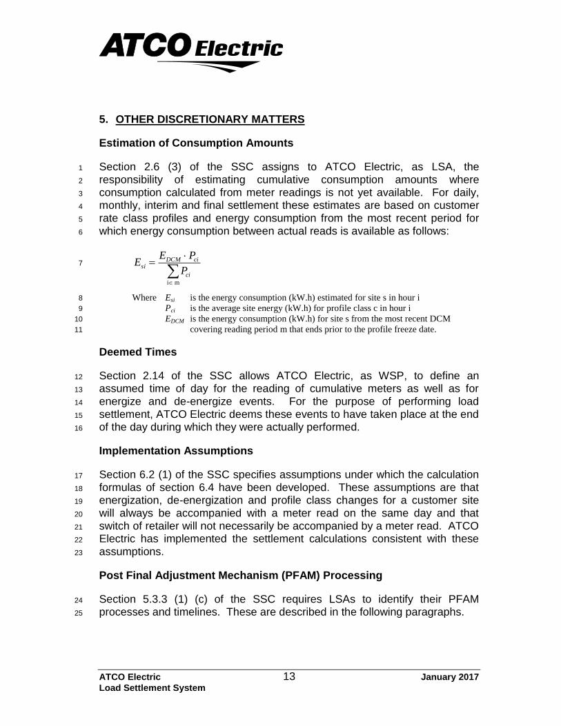
Section 2.6 (3) of the SSC assigns to ATCO Electric, as LSA, the 1
responsibility of estimating cumulative consumption amounts where 2
consumption calculated from meter readings is not yet available. For daily, 3
monthly, interim and final settlement these estimates are based on customer 4
rate class profiles and energy consumption from the most recent period for 5
which energy consumption between actual reads is available as follows: 6
m i
ci
ciDCMsi
P
PEE 7
Where Esi is the energy consumption (kW.h) estimated for site s in hour i 8
Pci is the average site energy (kW.h) for profile class c in hour i 9
EDCM is the energy consumption (kW.h) for site s from the most recent DCM 10
covering reading period m that ends prior to the profile freeze date. 11
Deemed Times
Section 2.14 of the SSC allows ATCO Electric, as WSP, to define an 12
assumed time of day for the reading of cumulative meters as well as for 13
energize and de-energize events. For the purpose of performing load 14
settlement, ATCO Electric deems these events to have taken place at the end 15
of the day during which they were actually performed. 16
Implementation Assumptions
Section 6.2 (1) of the SSC specifies assumptions under which the calculation 17
formulas of section 6.4 have been developed. These assumptions are that 18
energization, de-energization and profile class changes for a customer site 19
will always be accompanied with a meter read on the same day and that 20
switch of retailer will not necessarily be accompanied by a meter read. ATCO 21
Electric has implemented the settlement calculations consistent with these 22
assumptions. 23
Post Final Adjustment Mechanism (PFAM) Processing
Section 5.3.3 (1) (c) of the SSC requires LSAs to identify their PFAM 24
processes and timelines. These are described in the following paragraphs. 25
ATCO Electric 14 January 2017
Load Settlement System
Following the final settlement run each month, an automated process 1
identifies changes to cumulative consumption site data since the previous 2
final settlement run. If the affected periods are already final settled, the 3
process produces the required RSA transactions. These transactions are 4
reviewed and submitted by the end of the 7th business day of the following 5
month (see SSC Section 5.3.7 (1)). All other changes to data between the 6
same two final settlement runs affecting periods already final settled are 7
identified manually. The required RSA and/or TAA transactions are manually 8
prepared and submitted at the same time as the RSA transactions produced 9
by the automated process. 10
Daily profiles are used in producing the RSA transaction set only in the case 11
where final profiles are not available. The use of daily profiles in such cases 12
allows RSA transactions to be issued one month earlier with little impact on 13
the result. 14
Section 5.3.3 (1) (c) of the SSC requires parties to withhold submitting a 15
PFAM Application Form after identifying an error until the LSA is able to 16
process the RSA transaction set as per the LSA’s processes and timelines. 17
For ATCO Electric this withholding period is 45 calendar days. This allows for 18
the maximum number of days between final settlement runs and the 19
maximum number of days between the last final settlement run and date the 20
RSA and/or TAA transactions must be submitted. 21
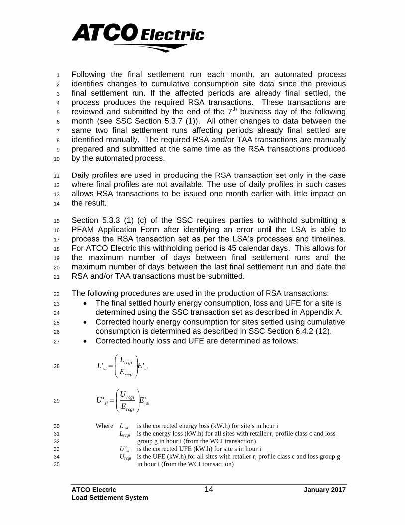
The following procedures are used in the production of RSA transactions: 22
The final settled hourly energy consumption, loss and UFE for a site is 23
determined using the SSC transaction set as described in Appendix A. 24
Corrected hourly energy consumption for sites settled using cumulative 25
consumption is determined as described in SSC Section 6.4.2 (12). 26
Corrected hourly loss and UFE are determined as follows: 27
si
rcgi
rcgi
si EE
LL ''
28
si
rcgi
rcgi
si EE
UU ''
29
Where L’si is the corrected energy loss (kW.h) for site s in hour i 30
Lrcgi is the energy loss (kW.h) for all sites with retailer r, profile class c and loss 31
group g in hour i (from the WCI transaction) 32
U’si is the corrected UFE (kW.h) for site s in hour i 33
Urcgi is the UFE (kW.h) for all sites with retailer r, profile class c and loss group g 34
in hour i (from the WCI transaction) 35

ATCO Electric 15 January 2017
Load Settlement System
E’si is the corrected energy consumption (kW.h) for site s in hour i 1
Ercgi is the energy consumption (kW.h) for all sites with retailer r, profile class c 2
and loss group g in hour i (from the WCI transaction) 3
Cumulative Metering Validation Test Parameters
Section 10.3.2.1 of the SSC requires MDMs to make available to the market 4
the high and low limits for usage and demand in their cumulative metering 5
validation tests. For this information please refer to the AUC Rule 004 Alberta 6
Tariff Billing Code Rules, section A1.2. 7

ATCO Electric 16 January 2017
Load Settlement System
APPENDIX A – CALCULATION OF HOURLY ENERGY CONSUMPTION, LOSS AND UFE
In this appendix, a method is provided for determining hourly customer site 1
energy consumption, loss and UFE from the SSC transaction set. 2
3
In the following: 4
The WCI, WSD and SPI transactions used must be from the same 5
settlement run. 6
Cumulative meter reads, energization, de-energization, profile class 7
changes and retailer switches are all deemed to occur on daily 8
boundaries. 9
Site s is a member of profile class c as well as loss group g and is enrolled 10
to retailer r on day d which is in meter reading period m. 11
Hour i is within day d. 12
Cumulative Metered and Unmetered Sites
Hourly energy consumption, loss and UFE for cumulative metered and 13
unmetered sites can be calculated as follows: 14
d i
rcgi
rcgisd
siE
EEE 15
d i
rcgi
rcgisd
siL
LLL 16
d i
rcgi
rcgisd
siU
UUU 17
Where Esi is the energy consumption (kW.h) for site s in hour i 18
Esd is the energy consumption (kW.h) for site s in day d (from the WSD 19
transaction) 20
Ercgi is the energy consumption (kW.h) for all sites with retailer r, profile class c 21
and loss group g in hour i (from the WCI transaction) 22
Lsi is the energy loss (kW.h) for site s in hour i 23
Lsd is the energy loss (kW.h) for site s in day d (from the WSD transaction) 24
Lrcgi is the energy loss (kW.h) for all sites with retailer r, profile class c and loss 25
group g in hour i (from the WCI transaction) 26
Usi is the UFE (kW.h) for site s in hour i 27
Usd is the UFE (kW.h) for site s in day d (from the WSD transaction) 28
ATCO Electric 17 January 2017
Load Settlement System
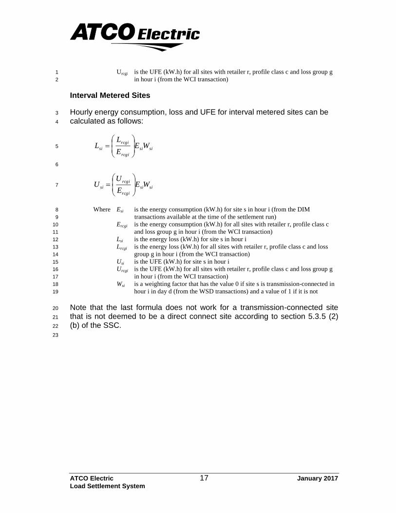
Urcgi is the UFE (kW.h) for all sites with retailer r, profile class c and loss group g 1
in hour i (from the WCI transaction) 2
Interval Metered Sites
Hourly energy consumption, loss and UFE for interval metered sites can be 3
calculated as follows: 4
sisi
rcgi
rcgi
si WEE
LL
5
6
sisi
rcgi
rcgi
si WEE
UU
7
Where Esi is the energy consumption (kW.h) for site s in hour i (from the DIM 8
transactions available at the time of the settlement run) 9
Ercgi is the energy consumption (kW.h) for all sites with retailer r, profile class c 10
and loss group g in hour i (from the WCI transaction) 11
Lsi is the energy loss (kW.h) for site s in hour i 12
Lrcgi is the energy loss (kW.h) for all sites with retailer r, profile class c and loss 13
group g in hour i (from the WCI transaction) 14
Usi is the UFE (kW.h) for site s in hour i 15
Urcgi is the UFE (kW.h) for all sites with retailer r, profile class c and loss group g 16
in hour i (from the WCI transaction) 17
Wsi is a weighting factor that has the value 0 if site s is transmission-connected in 18
hour i in day d (from the WSD transactions) and a value of 1 if it is not 19
Note that the last formula does not work for a transmission-connected site 20
that is not deemed to be a direct connect site according to section 5.3.5 (2) 21
(b) of the SSC. 22
23
ATCO Electric 18 January 2017
Load Settlement System
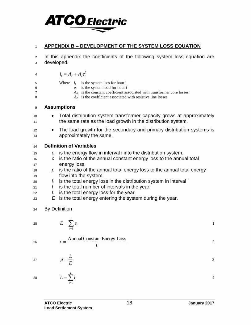
APPENDIX B – DEVELOPMENT OF THE SYSTEM LOSS EQUATION 1
In this appendix the coefficients of the following system loss equation are 2
developed. 3
2
20 ii eAAl 4
Where li is the system loss for hour i 5
ei is the system load for hour i 6
A0 is the constant coefficient associated with transformer core losses 7
A2 is the coefficient associated with resistive line losses 8
Assumptions 9
Total distribution system transformer capacity grows at approximately 10
the same rate as the load growth in the distribution system. 11
The load growth for the secondary and primary distribution systems is 12
approximately the same. 13
Definition of Variables 14
ei is the energy flow in interval i into the distribution system. 15
c is the ratio of the annual constant energy loss to the annual total 16
energy loss. 17
p is the ratio of the annual total energy loss to the annual total energy 18
flow into the system 19
li is the total energy loss in the distribution system in interval i 20
I is the total number of intervals in the year. 21
L is the total energy loss for the year 22
E is the total energy entering the system during the year. 23
By Definition 24
I
i
ieE1
1 25
Lc
LossEnergy Constant Annual 2 26
E
Lp 3 27
I
i
ilL1
4 28
ATCO Electric 19 January 2017
Load Settlement System
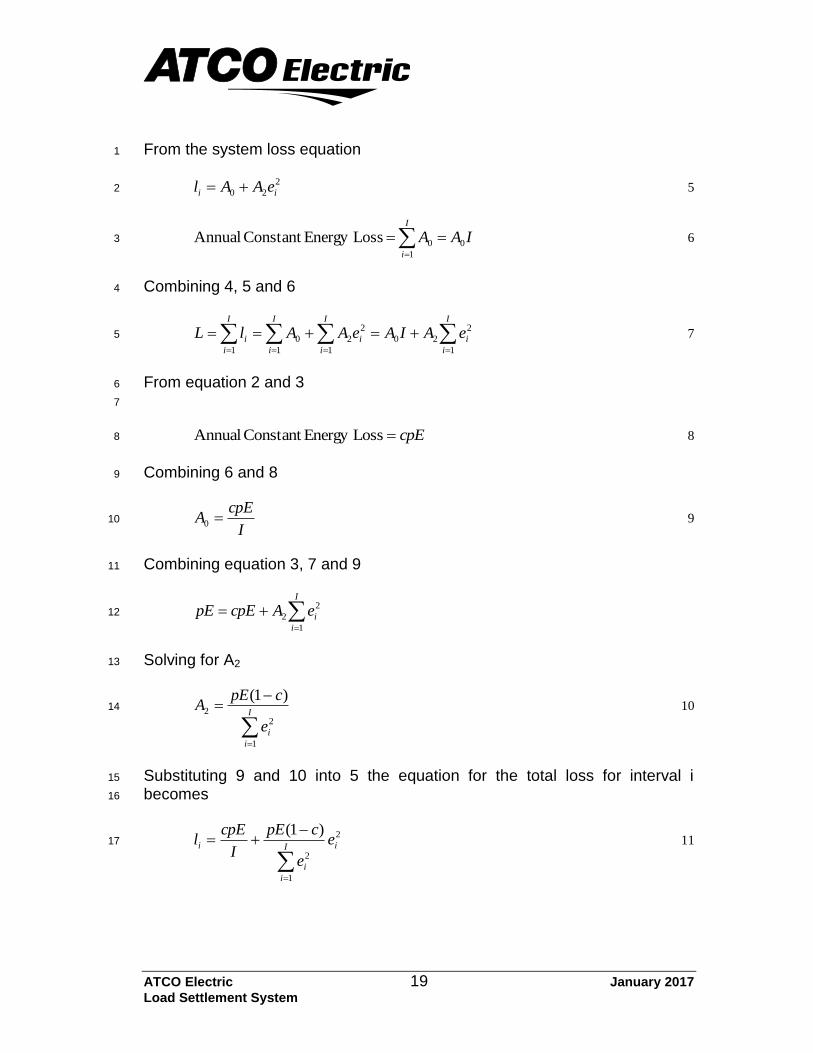
From the system loss equation 1
2
20 ii eAAl 5 2
IAAI
i
0
1
0LossEnergy Constant Annual
6 3
Combining 4, 5 and 6 4
I
i
i
I
i
i
I
i
I
i
i eAIAeAAlL1
2
20
1
2
2
1
0
1
7 5
From equation 2 and 3 6
7
cpELossEnergy Constant Annual 8 8
Combining 6 and 8 9
I
cpEA 0 9 10
Combining equation 3, 7 and 9 11
I
i
ieAcpEpE1
2
2 12
Solving for A2 13
I
i
ie
cpEA
1
22
)1( 10 14
Substituting 9 and 10 into 5 the equation for the total loss for interval i 15
becomes 16
2
1
2
)1(iI
i
i
i e
e
cpE
I
cpEl
11 17
ATCO Electric 20 January 2017
Load Settlement System
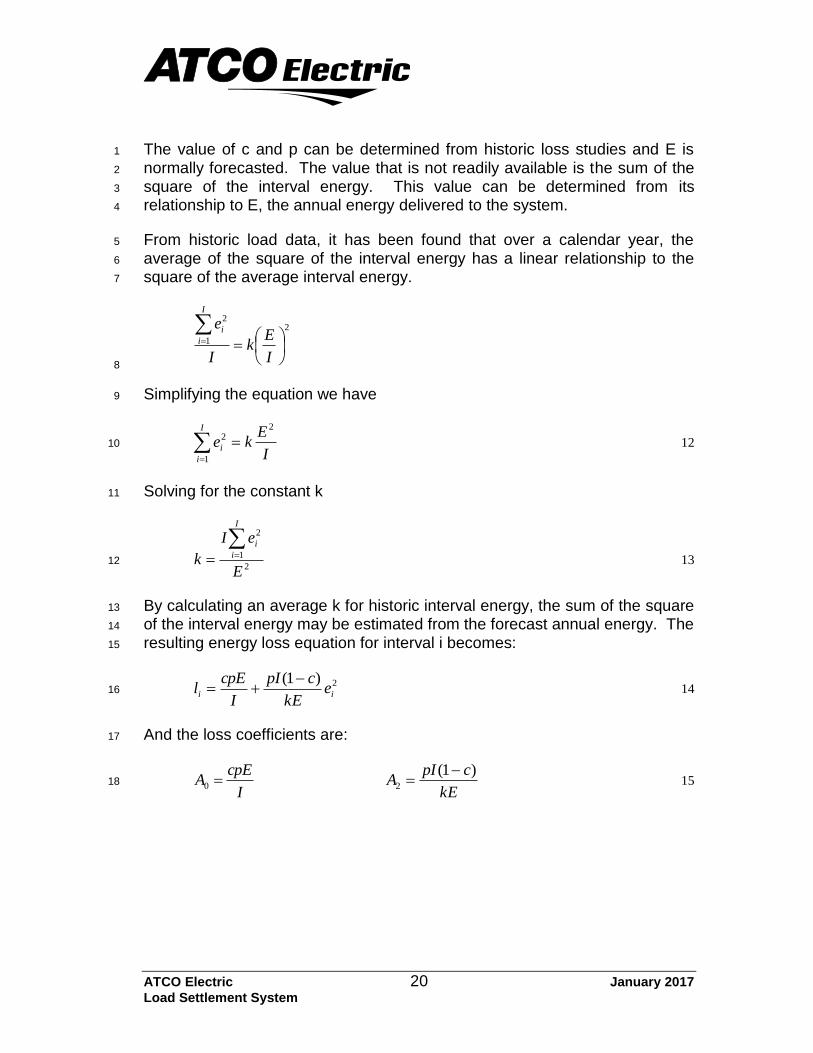
The value of c and p can be determined from historic loss studies and E is 1
normally forecasted. The value that is not readily available is the sum of the 2
square of the interval energy. This value can be determined from its 3
relationship to E, the annual energy delivered to the system. 4
From historic load data, it has been found that over a calendar year, the 5
average of the square of the interval energy has a linear relationship to the 6
square of the average interval energy. 7
2
1
2
I
Ek
I
eI
i
i
8
Simplifying the equation we have 9
I
Eke
I
i
i
2
1
2
12 10
Solving for the constant k 11
2
1
2
E
eI
k
I
i
i 13 12
By calculating an average k for historic interval energy, the sum of the square 13
of the interval energy may be estimated from the forecast annual energy. The 14
resulting energy loss equation for interval i becomes: 15
2)1(ii e
kE
cpI
I
cpEl
14 16
And the loss coefficients are: 17
I
cpEA 0
kE
cpIA
)1(2
15 18
ATCO Electric 21 January 2017
Load Settlement System
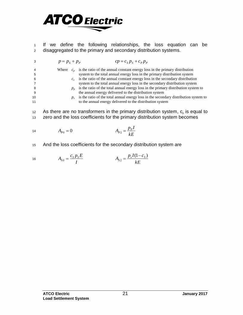
If we define the following relationships, the loss equation can be 1
disaggregated to the primary and secondary distribution systems. 2
PS ppp PPSS pcpccp 3
Where cp is the ratio of the annual constant energy loss in the primary distribution 4
system to the total annual energy loss in the primary distribution system 5
cs is the ratio of the annual constant energy loss in the secondary distribution 6
system to the total annual energy loss in the secondary distribution system 7
pp is the ratio of the total annual energy loss in the primary distribution system to 8
the annual energy delivered to the distribution system 9
ps is the ratio of the total annual energy loss in the secondary distribution system to 10
to the annual energy delivered to the distribution system 11
As there are no transformers in the primary distribution system, cp is equal to 12
zero and the loss coefficients for the primary distribution system becomes 13
00 PA kE
IpA P
P 2 14
And the loss coefficients for the secondary distribution system are 15
I
EpcA SS
S 0 kE
cIpA Ss
S
)1(2
16