Embed Size (px)
Citation preview
Air TrafficControl
Test Preparation
ATC_2008b:Layout 1 11/24/08 1:14 PM Page i

ATC_2008b:Layout 1 11/24/08 1:14 PM Page ii
Air TrafficControlTestPreparation
N E W Y O R K
®
ATC_2008b:Layout 1 11/24/08 1:14 PM Page iii

Copyright © 2009 LearningExpress, LLC
All rights reserved under International and Pan-American copyright conventions.
Published in the United States by LearningExpress, LLC, New York.
Library of Congress Control Number: 2008941611
A copy of this title is on file with the Library of Congress.
Printed in the United States of America
9 8 7 6 5 4 3 2 1
First Edition
ISBN: 978-1-57685-665-9
Regarding the Information in This Book
We attempt to verify the information presented in our books prior to publication. It is always a good idea,
however, to double-check such important information as qualifications, pre-employment testing, and
applications procedures with the Federal Aviation Administration, as such information can change from time
to time.
For more information or to place an order, contact LearningExpress at:
2 Rector Street
26th Floor
New York, NY 10006
Or visit us at:
www.learnatest.com
ATC_2008b:Layout 1 11/24/08 1:14 PM Page iv
v
List of Contributors vii
How to Use This Book xi
CHAPTER 1 Overview of Air Traffic Control 1
CHAPTER 2 The Air Traffic Control System 17
CHAPTER 3 Weather and Air Traffic Control 37
CHAPTER 4 Charting and Air Traffic Control 59
CHAPTER 5 Analogies 67
Practice Test 1—Analogy Test 75
CHAPTER 6 Angles and Applied Math 93
Practice Test 2—Angles Test 105
Practice Test 3—Applied Math Test 137
CHAPTER 7 Scan and Dial Reading 159
Practice Test 4—Scan Test 169
Practice Test 5—Dial Reading Test 195
CHAPTER 8 Letter Factory and Traffic Scenarios 219
Practice Test 6—Letter Factory Test 229
Practice Test 7—Air Traffic Scenarios Test (ATST) 255
Practice Test 8—Experience Questionnaire 285
Appendix 287
Glossary 305
Contents
ATC_2008b:Layout 1 11/24/08 1:14 PM Page v

ATC_2008b:Layout 1 11/24/08 1:14 PM Page vi

vii
List of Contributors
LindaM.Bracewell is an air traffic control instructor at Minneapolis College, Eden Prairie, Minneapolis, where
she has taught the basics of air traffic control to over 1,200 students, 90 percent of whom gained employment as
FAA en route controllers or are in successful training status. Bracewell previously taught air traffic control at Acad-
emy College in Bloomington,Minnesota, and worked for eight years as an en route controller at Minneapolis En
Route Center in Farmington,Minnesota.Her education includes a bachelor’s degree in psychology from St.Cloud
University, St. Cloud,Minnesota, and amaster’s degree in rehabilitation counseling and psychology from theUni-
versity of Minnesota,Minneapolis,Minnesota. She is currently pursuing a doctorate degree in education with an
emphasis on technology at St. Mary’s University, Minneapolis, Minnesota. She is a member of Women in Avia-
tion International and a private pilot. She resides in Apple Valley, Minnesota.
Greg Michael Thibeault is an assistant professor of air traffic control at Daniel Webster College, Nashua, New
Hampshire, and has over 19 years of experience as an air traffic control specialist (ATCS) for the FAA in Denver,
Colorado. He also serves as an air traffic control consultant for UFA, Inc., an industry leader in air traffic control
simulation and voice recognition and response (VRR). Thibeault is FAA certified as both an air traffic control
instructor and evaluator in a Level 11 TRACON. His education includes an MBA in aviation professionals from
Daniel Webster College, Nashua, New Hampshire, and a bachelor’s degree in business management from Park
University, Parkville, Missouri. Thibeault resides in Fitchburg, Massachusetts.
Mark J.Lewis is a freelance science writer and editor and a former algebra, physics, and biology teacher for Char-
lottesville City Schools in Virginia. Lewis holds a bachelor’s degree in biology and environmental studies from
Gettysburg College, Gettysburg, Pennsylvania, and amaster’s degree in applied ecology and conservative biology
from Frostburg State University, Frostburg,Maryland.He resides in Charlottesville,Virginia, and is a member of
the National Association of Science Writers.
ATC_2008b:Layout 1 11/24/08 1:14 PM Page vii
–CHAPTER TITLE–
viii
Timothy K. Trowbridge is a freelance mathematics writer and a software testing specialist and learning advisor
for MindLeaders, Columbus, Ohio. He holds a bachelor’s degree in mathematics from Hawaii Loa College,
Kaneohe, Hawaii. He resides in Gahanna, Ohio.
Northeast Editing, Inc., a full-service development house in Jenkins Township, Pennsylvania, has been creating
educational content for publishers since 1992. The company’s experienced authors, instructors, editors, and
designers produce print and online test-preparation products for students of all ages. Northeast Editing, Inc. is
a member of the American Book Producers’ Association (ABPA) and the Association of Educational Publishers
(AEP).
–LIST OF CONTRIBUTORS–
ATC_2008b:Layout 1 11/24/08 1:14 PM Page viii
Air TrafficControl
Test Preparation
ATC_2008b:Layout 1 11/24/08 1:14 PM Page ix

ATC_2008b:Layout 1 11/24/08 1:14 PM Page x
xi
Congratulations on deciding to become an air traffic controller! Air traffic control is a challenging,
exciting career with great pay and benefits.Most controllers work for the Federal AviationAdmin-
istration (FAA). To become a controller for the FAA, you must graduate from a college or univer-
sity offering the Air Traffic Collegiate Training Initiative (AT-CTI) program. This program is designed to provide
qualified applicants with the knowledge they need to begin working as air traffic controllers. A number of schools
across the country offer this program.Prior to graduation, youwill be required to take a pre-employment test called
the Air Traffic Selection and Training (AT-SAT). This is an eight-hour, computerized exam that tests your aptitude
to become a successful air traffic controller.Youmust score 70 percent or higher on theAT-SAT to be considered for
employment. This book will give you the knowledge and practice you need to score well on this test.
� Chapter 1—Overview of Air Traff ic Control
In this chapter, you will learn what it is like to be an air traffic controller and the types of air traffic control jobs.
You will learn the qualifications needed to become a controller and the parts of the AT-SAT.
� Chapter 2—The Air Traff ic Control System
The air traffic control system is a vast network of people and equipment working together to ensure the safety of
aircraft. In this chapter, you will learn the essentials of this system, including navigation, airways, and
communication.
How to Use This Book
ATC_2008b:Layout 1 11/24/08 1:14 PM Page xi
–CHAPTER TITLE–
xii
� Chapter 3—Weather and Air Traff ic Control
Weather conditions significantly impact the aviation industry. This chapter teaches you how to access weather
forecasts and how to read weather reports such as the Meteorological Aviation Report (METAR).
� Chapter 4—Chart ing and Air Traff ic Control
Both controllers and pilots use aeronautical charts for navigation.Aeronautical charts illustrate topography, such
as landmarks, and the location of navigational aids for pilots and controllers. In this chapter, you will learn how
airspace, navigation aids, airways, and airports appear on charts.You will learn about common visual flight rules
(VFR) and instrument flight rules (IFR) charts.
� Chapter 5—Analogies
The Analogy Test is a cognitive test on the AT-SAT. On this test, you will answer questions about word and visual
analogies. Each question has three boxes. The first box contains a complete analogy. The second box contains part
of an analogy and a question mark, and the third box contains four answer options. This chapter will teach you
how to determine the relationship expressed in an analogy. Following the chapter is Practice Test 1, in which you
will answer 100 analogy questions.
� Chapter 6—Angles and Appl ied Math
Controllers must be able to perform mathematical calculations, so two of the cognitive tests on the AT-SAT are
about math: the Angles Test and the Applied Math Test. On the Angles Test, you will have to estimate the meas-
urement of angles.On theAppliedMath Test, you will have to calculate distance problems. This chapter will show
you how to do this. Following the chapter are Practice Test 2, which has 100 practice questions for theAngles Test,
and Practice Test 3, which has 100 practice questions for the Applied Math Test.
� Chapter 7—Scan and Dial Reading
Controllers must correctly interpret visual information tomaintain separation between aircraft.On the Scan Test,
you will have to quickly view a computer screen and enter an identification number for each data block containing
a number outside a given range. On the Dial Reading Test, you will have to correctly read the kind of dials you
–HOW TO USE THIS BOOK–
ATC_2008b:Layout 1 11/24/08 1:14 PM Page xii
–CHAPTER TITLE–
xiii
might see on an aircraft’s instrument panel. Following the chapter are Practice Test 4,which has 100 practice ques-
tions for the Scan Test, and Practice Test 5, which has 100 practice questions for the Dial Reading Test.
� Chapter 8—Letter Factory and Air Traff ic Scenarios
The Letter Factory Test and the Air Traffic Scenario Test are cognitive tests on the AT-SAT. On the Letter Factory
Test, you will view four factory assembly lines, each with a conveyor belt and a loading area. You will use a com-
puter mouse to drag the letters that appear on the belt into the appropriate box in the loading area. On the Air
Traffic Scenario Test, you will view data blocks on a computer screen that represent aircraft. You will use a com-
puter mouse to issue commands to maintain separation between aircraft. Following the chapter are Practice Test
6, which has 100 practice questions for the Letter Factory Test, and Practice Test 7, which has 100 practice ques-
tions for the Air Traffic Scenario Test. Also following this chapter is Practice Test 8, an experience questionnaire.
This questionnaire is the only non-cognitive test on the AT-SAT.
–HOW TO USE THIS BOOK–
ATC_2008b:Layout 1 11/24/08 1:14 PM Page xiii

ATC_2008b:Layout 1 11/24/08 1:14 PM Page xiv
1CHAPTER SUMMARYMost air traffic controllers work for the Federal Aviation Administration
(FAA). Controllers must be good at multitasking and able to work in
stressful situations. Most graduate from an Air Traffic College Training
Initiative (AT-CTI) program at an FAA-approved college with a two- or
four-year degree. Candidates in this program must take and pass an
Air Traffic Selection and Training Test (AT-SAT) before graduating.
Overview of AirTraffic Control
C H A P T E R
Years ago, only a few planes flew across America’s skies, so air traffic controllers, people in towers
and on the ground who monitor and control the flow of aircraft into and out of airports, were
unnecessary. Times soon changed, however.Asmore andmore planes transported people and goods
from state to state and from country to country, it became apparent that rules were needed to avoid collisions.
On May 20, 1926, the United States passed the Air Commerce Act, which called upon the aviation indus-
try to improve and maintain safety standards. The act also put the secretary of commerce in charge of creating
and enforcing air traffic rules, licensing pilots, inspecting and certifying aircraft, and creating new navigation aids.
The first rules regarding aviation were extremely simplistic—perhaps even humorous—compared to today’s stan-
dards. One rule asked pilots to look around before taking off to avoid hitting other planes.
As air traffic increased, airport operators realized that they could not rely solely on pilots’ eyes to avoid col-
lisions. Using visual signals, they created an early form of air traffic control (ATC). They hired flagmen,men who
stood on the field waving flags, to communicate with pilots.
When aircraft began using radio communication, radio-equipped ATC towers replaced flagmen. In 1930,
the first radio-equipped control tower in the United States began operating at the Cleveland Municipal Airport.
1
ATC_2008b:Layout 1 11/24/08 1:14 PM Page 1
Soonmanymore airports across the country had built
control towers.
Today, the Federal Aviation Administration
(FAA) employs approximately 14,000 air traffic con-
trollers who are responsible for directing the flow of air
traffic and ensuring that aircraft fly at a safe distance
from one another.
� Nature of the Work
Being an air traffic controller is not easy, and the job is
not for everyone. Controllers are part of an air traffic
control system, a vast network of people and equip-
ment whose purpose is to ensure the safety of aircraft
and passengers. Controllers must work quickly and
efficiently—there is little or no margin for error. They
must concentrate fully on several planes simultane-
ously to ensure that pilots receive the correct instruc-
tions. During arrival and departure “rushes,” the job
can be stressful and exhausting.During nonpeak peri-
ods, however, controllers enjoy a relatively calm work
environment.
Controllers use radar, but they sometimes rely on
their own observations to guide pilots safely to and
from airports. For example, a controller in a control
tower might visually observe air traffic coming into
and going out of an airport.
Controllers work very hard, but they are well paid
and receive excellent benefits. Many control towers
operate 24–7, 365 days a year, so controllers have
opportunities to earn additional compensation. They
typically earn an additional 10 percent of their rate for
working evening shifts and 25 percent of their rate for
working on Sundays. Controllers who work on federal
holidays receive double-time pay, and those who work
overtime receive time-and-a-half.
The FAA employsmost controllers.Most work at
airports, but somework at air route traffic control cen-
ters (ARTCCs), which are located in various places.
Some controllers conduct research at the William J.
Hughes Technical Center (WJHTC) near Atlantic City,
New Jersey.A small number of controllers work for the
Department of Defense (DoD) and private ATC
companies.
–OVERVIEW OF AIR TRAFFIC CONTROL–
2
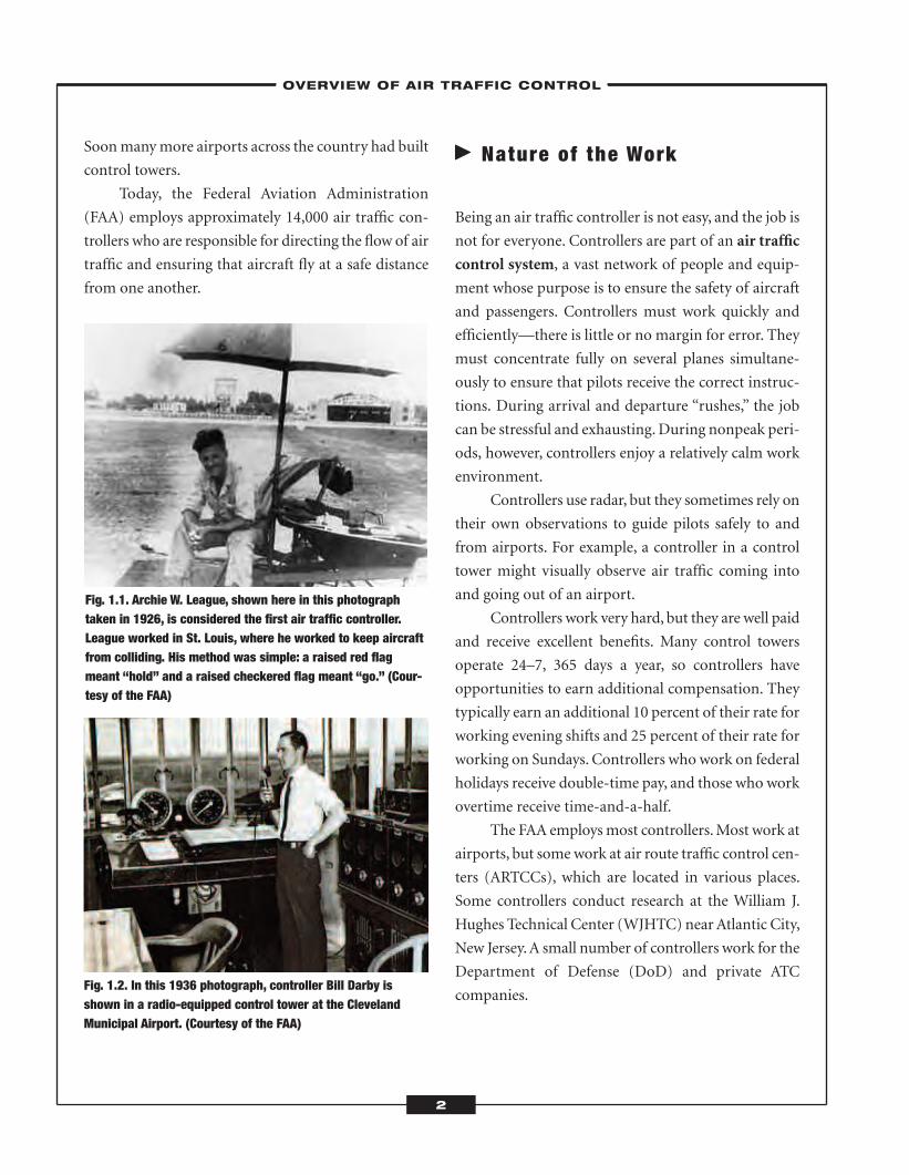
Fig. 1.1. Archie W. League, shown here in this photographtaken in 1926, is considered the first air traffic controller.League worked in St. Louis, where he worked to keep aircraftfrom colliding. His method was simple: a raised red flagmeant “hold” and a raised checkered flag meant “go.” (Cour-tesy of the FAA)
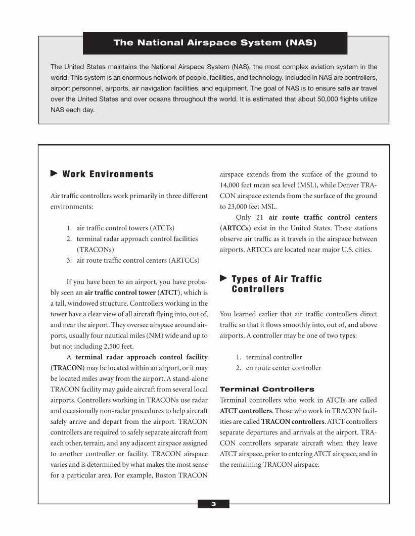
Fig. 1.2. In this 1936 photograph, controller Bill Darby isshown in a radio-equipped control tower at the ClevelandMunicipal Airport. (Courtesy of the FAA)
ATC_2008b:Layout 1 11/24/08 1:14 PM Page 2
� Work Environments
Air traffic controllers work primarily in three different
environments:
1. air traffic control towers (ATCTs)
2. terminal radar approach control facilities
(TRACONs)
3. air route traffic control centers (ARTCCs)
If you have been to an airport, you have proba-
bly seen an air traffic control tower (ATCT), which is
a tall, windowed structure. Controllers working in the
tower have a clear view of all aircraft flying into, out of,
and near the airport. They oversee airspace around air-
ports, usually four nautical miles (NM)wide and up to
but not including 2,500 feet.
A terminal radar approach control facility
(TRACON)may be located within an airport, or it may
be located miles away from the airport. A stand-alone
TRACON facility may guide aircraft from several local
airports. Controllers working in TRACONs use radar
and occasionally non-radar procedures to help aircraft
safely arrive and depart from the airport. TRACON
controllers are required to safely separate aircraft from
each other, terrain, and any adjacent airspace assigned
to another controller or facility. TRACON airspace
varies and is determined by whatmakes themost sense
for a particular area. For example, Boston TRACON
airspace extends from the surface of the ground to
14,000 feet mean sea level (MSL), while Denver TRA-
CON airspace extends from the surface of the ground
to 23,000 feet MSL.
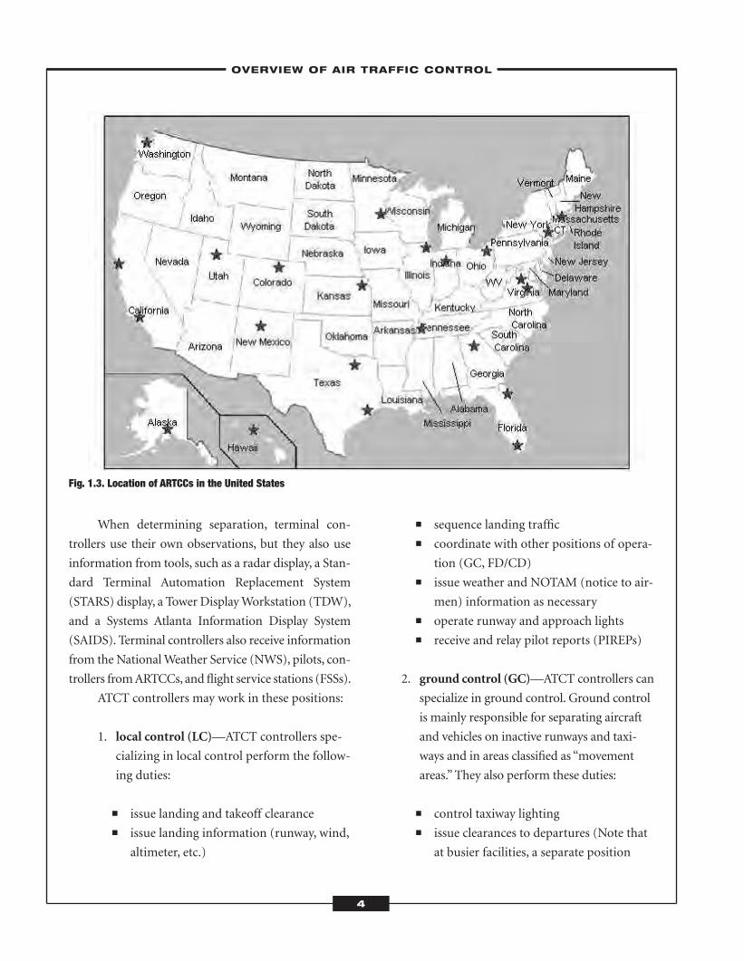
Only 21 air route traffic control centers
(ARTCCs) exist in the United States. These stations
observe air traffic as it travels in the airspace between
airports. ARTCCs are located near major U.S. cities.
� Types of Air Traff icControl lers
You learned earlier that air traffic controllers direct
traffic so that it flows smoothly into, out of, and above
airports. A controller may be one of two types:
1. terminal controller
2. en route center controller
Terminal Controllers
Terminal controllers who work in ATCTs are called
ATCTcontrollers. Those whowork in TRACON facil-
ities are calledTRACONcontrollers.ATCT controllers
separate departures and arrivals at the airport. TRA-
CON controllers separate aircraft when they leave
ATCT airspace, prior to enteringATCT airspace, and in
the remaining TRACON airspace.
3
The United States maintains the National Airspace System (NAS), the most complex aviation system in the
world. This system is an enormous network of people, facilities, and technology. Included in NAS are controllers,
airport personnel, airports, air navigation facilities, and equipment. The goal of NAS is to ensure safe air travel
over the United States and over oceans throughout the world. It is estimated that about 50,000 flights utilize
NAS each day.
The National Airspace System (NAS)
ATC_2008b:Layout 1 11/24/08 1:14 PM Page 3
When determining separation, terminal con-
trollers use their own observations, but they also use
information from tools, such as a radar display, a Stan-
dard Terminal Automation Replacement System
(STARS) display, a Tower DisplayWorkstation (TDW),
and a Systems Atlanta Information Display System
(SAIDS). Terminal controllers also receive information
from the NationalWeather Service (NWS), pilots, con-
trollers fromARTCCs, and flight service stations (FSSs).
ATCT controllers may work in these positions:
1. local control (LC)—ATCT controllers spe-
cializing in local control perform the follow-
ing duties:
� issue landing and takeoff clearance� issue landing information (runway, wind,
altimeter, etc.)
� sequence landing traffic� coordinate with other positions of opera-
tion (GC, FD/CD)� issue weather and NOTAM (notice to air-
men) information as necessary� operate runway and approach lights� receive and relay pilot reports (PIREPs)
2. ground control (GC)—ATCT controllers can
specialize in ground control. Ground control
is mainly responsible for separating aircraft
and vehicles on inactive runways and taxi-
ways and in areas classified as “movement
areas.” They also perform these duties:
� control taxiway lighting� issue clearances to departures (Note that
at busier facilities, a separate position
4
Fig. 1.3. Location of ARTCCs in the United States
–OVERVIEW OF AIR TRAFFIC CONTROL–
ATC_2008b:Layout 1 11/24/08 1:14 PM Page 4
known as clearance delivery issues IFR
clearances in order to reduce congestion
on the GC frequency.)� coordinate traffic movements affecting
LC� issue weather and NOTAM information
as appropriate� control vehicles on the airport movement
area (other than runways)� direct emergency equipment to necessary
locations� relay runway and taxiway condition
information to airport management
3. flight data (FD)—ATCT controllers special-
izing in flight data (FD) perform these
duties:
� receive and relay departures clearances
to GC� relay weather and NOTAM information
to other positions of operation� forward departure times to the ARTCC� aid control positions (LC and GC) by
relaying information as needed� collect, tabulate, and store daily records
TRACON controllers are responsible for a block
of airspace called a sector. TRACON controllers work
in teams to guide aircraft into and out of an area about
50 miles outside the airport and often up to about
10,000 feet. TRACON controllers can be divided into
two basic types:
1. departure controllers
2. arrival controllers
Departure ControllersTRACON departure controllerswork in a series using
radar tomonitor an aircraft as it ascends through their
sector. Once the aircraft leaves TRACON airspace, a
departure controller passes off responsibility for the
aircraft to a controller in the ARTCC. This is called a
hand-off.
Arrival ControllersArrival controllers monitor aircraft transitioning
from the en route phase to the approach phase. Once
the aircraft is within the airport’s airspace, a local con-
troller in the ATCT takes over, and TRACON con-
trollers no longer monitor the aircraft.
En Route Center Controllers
En route center controllers, often called center con-
trollers, monitor aircraft while they are in their
ARTCC’s airspace.At least two center controllersmon-
itor each aircraft: the radar associate controller and the
radar controller. The radar associate controller
receives flight-plan information before the aircraft
enters the airspace and assists the radar controller,
who is in charge of air-to-ground communication and
aircraft separation. A third controller, called the radar
hand-off controller, will assist the other two when
traffic is heavy. The radar hand-off controller closely
watches the radar screen. These controllers inform
pilots of speed and altitude and give them directions to
maintain safe separation.
� Qual i t ies of an Air Traff icControl ler
According to the FAA, air traffic controllers must be
motivated, decisive, committed, and self-confident.
Theymust be able to remain calmwhile working under
stressful conditions. Controllers must be experts at
–OVERVIEW OF AIR TRAFFIC CONTROL–
5
ATC_2008b:Layout 1 11/24/08 1:14 PM Page 5
multitasking, so they can clearly communicate the cor-
rect instructions to several pilots who are navigating
different routes. A controller may be helping a pilot
land a plane, helping another pilot take off, and
informing yet another of a changing weather pattern
monitored on the computer screen. Controllers must
be able to speak clearly and have a good command of
the English language. They are typically individuals
who enjoy the excitement of working in a fast-paced
environment.
� How to Become an Air Traff icControl ler
The steps to becoming an air traffic controller are very
specific. Most individuals the FAA considers hiring as
air traffic controllers have graduated from an approved
Air Traffic College Training Initiative (AT-CTI) pro-
gram with a two- or four-year degree.While complet-
ing the program, these individuals must take and pass
the Air Traffic Selection and Training Test (AT-SAT).
They must also receive a school recommendation and
pass a medical examination, drug screening, and secu-
rity clearance. Once they are selected for employment
as air traffic controllers, theymust attend the FAAAcad-
emy inOklahomaCity for training. Exceptions include
� controllers with former military controlling
experience� former controllers who were disqualified
(i.e., medical disqualification)� members of the general public who have
responded to an FAA advertisement
Qualifications
To become an air traffic controller, you must
� be a U.S. citizen� speak English clearly� complete an interview� have the proper training or experience� achieve a score of at least 70 on the AT-SAT� be hired by your 31st birthday� pass a medical examination� pass a security investigation
AT-CTI Programs
The FAA partners with several colleges to offer two-
and four-year degrees in basic ATC. This partnership,
called theAir Traffic Collegiate Training Initiative (AT-
CTI) program, helps candidates qualify to become air
traffic controllers.Graduates of the program bypass the
first five weeks of qualification training at the FAA
Academy in Oklahoma City. The first five weeks of
training are referred to as the Air Traffic Basics
6
To maintain safe separation, aircraft flying at altitudes below 29,000 feet must be separated by 1,000 feet, and
aircraft flying at altitudes higher than this must be separated by 2,000 feet.
Reduced vertical separation minimum (RVSM) is a procedure that will reduce the vertical space sep-
aration from 2,000 feet to 1,000 feet for aircraft flying at altitudes between 29,000 and 41,000 feet. This reduc-
tion will allow more planes to fly preferred routes. Having routes gives controllers greater flexibility, since this
makes it easier to route aircraft around storms.
Reduced Vertical Separation Minimum (RVSM)
ATC_2008b:Layout 1 11/24/08 1:14 PM Page 6

Course. Candidates who participate in theAT-CTI still
need to meet all other requirements of being an air
traffic controller. Participants in the AT-CTI take the
ATC pre-employment test, the AT-SAT.
Acceptance into an AT-CTI program is compet-
itive, but graduates from large, high-quality schools are
virtually guaranteed a job. The following schools cur-
rently offer AT-CTI programs:
Arizona State University
College of Technology and Innovation
Department of Aeronautical Management
Technology
7442 E. Tillman Ave.
Mesa, AZ 85212
POC: Verne Latham, lecturer
(480) 727-1652 (office)
(480) 727-1021 (department office)
The Community College of Baltimore County
Aviation Department AF-313
800 S. Rolling Rd.
Baltimore, MD 21228
POC: Douglas Williams, aviation program director
(410) 455-4157
Community College of Beaver County
Aviation Sciences Center
125 Cessna Dr.
Beaver Falls, PA 15010-1060
POC: James E. Scott
(724) 847-7000, ext. 209
DanielWebster College
20 University Dr.
Nashua, NH 03063-1300
POC: Peter Wyman, assistant professor (ATC)
(603) 577-6204
Dowling College
Dowling College–Brookhaven Campus
1300William Floyd Pkwy.
Shirley, NY 11967
POC: JohnWensveen, dean
(631) 244-1303
Embry-Riddle Aeronautical University–
Daytona Beach
Embry-Riddle Aeronautical University
600 S. Clyde Morris Blvd.
Daytona Beach, FL 32114-3900
POC: Sid McGuirk, associate professor and program
coordinator
(386) 226-7125
7
Flight service specialists use innovative technology to provide pilots with a range of services including the
interpretation of aeronautical, meteorological, and aviation information and emergency services. Flight service
specialists communicate with pilots who cannot communicate with a control tower. They can advise flying air-
craft when there is no active control tower, but they do not actively manage air traffic. In 2005, the FAA con-
tracted the management of flight service stations (FSSs) to the Lockheed-Martin Corporation, a technology
company.
Flight Service Specialists
ATC_2008b:Layout 1 11/24/08 1:14 PM Page 7

Florida Community College–Jacksonville
13450 Lake Fretwell St.
Jacksonville, FL 32221
POC: James B. Renninger, director of the Aviation
Center of Excellence
(904) 317-3801
Green River Community College–Main Campus
12401 SE 320th St.
Auburn,WA 98092-3622
POC: Curtis E. (Curt) Scott, aviation and
ATC instructor
(253) 833-9111, ext. 4335
Hampton University
Department of Aviation
Science & Technology Bldg., Rm. 269
Hampton, VA 23668
POC: Carey Freeman
(757) 727-5418
InterAmerican University of Puerto Rico–
Bayamon Campus
School of Aeronautics
PO Box 9066623
San Juan, PR 00906
POC: Mario Signoret, dean of the School of
Aeronautics
(787) 725-2062
Kent State University
PO Box 5190
Kent, OH 44242
POC: Isaac Richmond Nettey, associate dean of the
College of Technology and senior academic program
director of aeronautics
(330) 672-9476
Lewis University
One University Pkwy., Unit 282
Romeoville, IL 60446-2200
POC: Michael K. Streit, professor and assistant chair
(815) 836-5431
Metropolitan State College of Denver
Department of Aviation and Aerospace Science
Campus Box 30
PO Box 173362
Denver, CO 80217-3362
POC: James L. Simmons, PhD, JD, associate
professor of aviation and aerospace science
(303) 556-4452
Miami Dade College
500 College Terr.
Homestead, FL 33030
POC: Dionne Henry, program coordinator
(305) 237-5952
Middle Georgia College
Aviation Management
1100 Second St. SE
Cochran, GA 31014
POC: John Hunt, assistant professor of air traffic
control
(478) 448-4703
Middle Tennessee State University
1500 Greenland Dr., BAS S211
Murfreesboro, TN 37132
POC: Gail M. Zlotky, associate professor
(615) 898-2290
Minneapolis Community and Technical College
Air Traffic Control Training Program
10100 Flying Cloud Dr.
Eden Prairie, MN 55347
8
–OVERVIEW OF AIR TRAFFIC CONTROL–
ATC_2008b:Layout 1 11/24/08 1:14 PM Page 8
POC: Thomas Buzzard, manager
(952) 826-2406
(800) 475-2828
Mount San Antonio College
1100 N. Grand Ave.
Walnut, CA 91789-1399
POC: Robert Rogus, CTI coordinator
(909) 594-5611, ext. 3098
Purdue University
Department of Aviation Technology
Aviation Technology Bldg.
1401 Aviation Dr.
West Lafayette, IN 47907-2015
POC: Michael S. Nolan, professor of aviation
technology
(765) 494-9962
University of Alaska–Anchorage
Division of Aviation Technology
2811 Merrill Field Dr.
Anchorage, AK 99501
POC: Bill Butler
(907) 786-7212
University of North Dakota
3980 Campus Rd., Stop 9007
Grand Forks, ND 58202-9007
POC: Paul Drechsel, assistant professor and
codirector of ATC
(701) 777-4923
University of Oklahoma
1700 Lexington, Rm. 210
Norman, OK 73069
POC: Jim Hamm, director of the AT-CTI training
program
(405) 325-3586
Vaughn College of Aeronautics and Technology
86-01 Twenty-third Ave.
Flushing, NY 11369
POC: Domenic Proscia, associate professor and chair
(718) 429-6600, ext. 139
Formal Aviation Experience in
Place of Education
In some cases, those with significant aviation experi-
ence do not need formal education through anAT-CTI
program. This is often the case for veterans who had
military ATC experience, retired military controllers,
and current civilian air traffic controllers who have
been working in the field before the education require-
ment came into existence.
Controllers whowish to substitute experience for
education must have 52 consecutive weeks of ATC
experience and a working knowledge of the laws, rules,
and regulations applying to ATC.
Veterans with military ATC experience can be
hired through a Veteran’s Recruitment Appointment
(VRA). To be considered for a VRA, veterans must be
discharged from active duty or on terminal leave. They
may be
� disabled veterans� veterans separated from active duty within
three years� veterans who served on active duty in the
armed forces during a war� veterans who have received an armed forces
service medal
Open Advertisements
Occasionally, the FAA may advertise on its Web site
that it is taking applications for air traffic controllers
from the general public. The FAA reviews the applica-
tions it receives and chooses applicants to continue the
employment process.
9
–OVERVIEW OF AIR TRAFFIC CONTROL–
ATC_2008b:Layout 1 11/24/08 1:14 PM Page 9
The Air Traffic Selection and
Training Test (AT-SAT)
All applicants from AT-CTI programs and the general
public must take and pass the AT-SAT, a computerized
test consisting of eight sections and lasting about eight
hours. The sections of theAT-SAT are often referred to
as tests. The AT-SAT consists of seven cognitive tests
and one non-cognitive test. The non-cognitive test, the
Experience Questionnaire, is part of the AT-SAT but is
not counted as part of the total score. The following are
the eight sections, or tests, on the AT-SAT:
� Analogies� Angles� Applied Math� Scan� Dial Reading� Letter Factory� Air Traffic Scenarios� Experience Questionnaire
Analogies
The Analogy Test measures your ability to reason well,
an important trait for an air traffic controller.An anal-
ogy is a comparison of two things that are related in
some way. On the test, you will be shown an analogy,
such as hot :: cold. Then youwill be given part of a sec-
ond analogy, such as short :: ___. You will have to
choose the answer option that has the same relation-
ship as the words in the first analogy. In this case, you
would choose the answer option that means the oppo-
site of short—tall. About half the test contains visual
analogies, in which pictures are used instead of words.
You will learn about the Analogy Test in detail in
Chapter 5 of this book.
Angles
The Angles Test assesses your ability to recognize the
measurement of angles. Air traffic controllers need to
be able to do this to perform calculations on angles.
Two types of angle questions are on the AT-SAT. The
first type of question will show you an angle and ask
you to choose the answer option that best estimates its
measurement. The second type of question will give a
measurement and ask you to choose the angle that rep-
resents this measurement.
You will learn about the Angles Test in detail in
Chapter 6 of this book.
Applied Math
The Applied Math Test contains problems in which
youwill have to calculate time, distance, or speed based
on the information given in the problem.All questions
on this test will be about the movement of aircraft.
You will learn about the Applied Math Test in
detail in Chapter 6 of this book.
Scan
For the Scan Test, you will read a range of numbers
such as 102–560 that appear at the bottom of the
screen. Then youwill watch as blocks of data appear on
the screen,move in a straight line for a while, and then
disappear. These numbers will look like fractions:
above the line will be a letter and two numbers, as in
V36.Underneath the line will be a three-digit number,
such as 101. To pass the test, you will have to quickly
identify bottom numbers that fall outside the range
and type the top letter-number combination. You will
have 18 minutes to identify as many out-of-range
numbers as possible.
You will learn about the Scan Test in detail in
Chapter 7 of this book.
Dial Reading
TheDial Reading Test assesses your ability to read dials
quickly and correctly. You will be shown a panel of
seven dials in two rows and asked questions about
–OVERVIEW OF AIR TRAFFIC CONTROL–
10
ATC_2008b:Layout 1 11/24/08 1:14 PM Page 10
them. Typical dials might show air speed, altitude, or
fuel-air ratio.
You will learn about the Dial Reading Test in
detail in Chapter 7 of this book.
Letter Factory
The Letter Factory Test simulates four factory assem-
bly lines. The test measures your ability to (1) preplan
andmake decisions, (2) think ahead, and (3)maintain
situational awareness. Letters move down each con-
veyor belt, and youmust place the correctly colored let-
ter in the corresponding colored box at the bottom of
the screen using a computermouse. For example, a yel-
low letter must go into a yellow box. You will be asked
to perform other tasks as well, such as moving empty
boxes from the storage area to the loading area and
calling quality control if defective letters appear.
You will learn about the Letter Factory Test in
detail in Chapter 8 of this book.
Air Traffic Scenarios
The Air Traffic Scenarios Test simulates a radar screen
showing air traffic scenarios and tests your ability to
multitask.On this test, you will be asked to safely guide
aircraft on the screen to their destinations. You will be
scored on how quickly and accurately you do this. The
goal is to effectively move andmaintain space between
the aircraft, which are represented by data blocks. The
test rules are simple, however, and you do not need
knowledge of ATC to pass. The test stops periodically
to ask questions.
You will learn about theAir Traffic Scenarios Test
in detail in Chapter 8 of this book.
Experience Questionnaire
This part of the test simply asks you to respond to a
number of questions. Its goal is to assess your personal
attributes to see if you are well suited to work as an air
traffic controller.As you learned earlier in this section,
the results are not factored into your total AT-SAT
score. The test is similar to a psychological examination
and your results will be kept confidential.
You will be asked to respond to statements about
yourself using the following scale:
A. Definitely True
B. Somewhat True
C. Neither True nor False
D. Somewhat False
E. Definitely False
Sample statements:
1. pay attention to details
2. am friendly and easy to get to know
3. often get irritated and angry
4. forget things
5. leave a mess in my house
A School Recommendation
Before you can be awarded a job as an air traffic con-
troller, you need a school recommendation if you
attended a CTI school. An official school recom-
mendation shows that you have completed all aca-
demic requirements and should be considered for
employment.
Medical Exam
You must pass a medical examination before becom-
ing an air traffic controller.Most controllers must con-
tinue to take a medical exam every year. This medical
exam considers these aspects of a candidate’s physical
condition:
� vision, including color vision� hearing� cardiovascular fitness� neurological standards
11
–OVERVIEW OF AIR TRAFFIC CONTROL–
ATC_2008b:Layout 1 11/24/08 1:14 PM Page 11
� psychiatric standards� diabetes risk� substance abuse or dependency� psychological exams� general medical health
Drug Screening
You must also submit to a drug and alcohol screening
before becoming a controller. Most controllers must
continue to participate in drug screenings while they
are employed.
Security Clearance
Because air traffic controllers are responsible for the
lives of pilots and passengers, theymust obtain a secu-
rity clearance before obtaining employment. This
includes a background investigation. This investigation
looks into these issues:
� military discharge� statutory debarment� government loyalty� employment terminations� felony offenses� dishonesty in the application process� drug- or alcohol-related incidents� disregard of financial obligations� offenses involving firearms or explosives
The FAA Academy
After you meet all requirements and pass the AT-SAT,
you are eligible to work as an air traffic controller.Once
you reach this point in the process, your next step is to
attend the FAA Academy in Oklahoma City, Okla-
homa, for a 12- or 15-week training session, depend-
ing on whether you are hired for a terminal or an en
route position.
The session teaches future employees the funda-
mentals of the ATC system, FAA regulations, how to
use controller equipment, aircraft performance char-
acteristics, and specialized tasks. You will have to take
a qualifying test at the FAA Academy called the ATB
(Air Traffic Basic), which consists of questions relating
to ATC.
Graduates of the FAA Academy become devel-
opmental controllers and are assigned to an ATC
facility. Each ATC facility has its own requirements of
its employees, as does each ATC position. New con-
trollers usually take between two to four years to
become certified professional controllers. Controllers
with experience generally take less time to fulfill the
requirements of their position.
� Job Outlook, Salary, andBenef i ts
The U.S. Department of Labor projects the employ-
ment of air traffic controllers to grow by 10 percent
from 2006 to 2016. Most job opportunities are
expected to be the result of the retirement of existing
air traffic controllers, many of whom are expected to
retire over the next decade. Despite the increasing
number of job openings, however, the competition is
To become an air traffic controller, you must be 30 years old or younger. While this may seem unfair, most con-
trollers must retire by age 56. This is a short working career even for a young person. The age requirement helps
limit the pool of candidates to those who want to make air traffic control a career.
Air Traffic Controller Age Limitation
12
ATC_2008b:Layout 1 11/24/08 1:14 PM Page 12
still fierce. There may be more applicants for the AT-
CTI programs than there are job openings.
According to the U.S. Department of Labor, in
2006, the average annual salary of an air traffic con-
troller was $117,240. The middle 50 percent earned
between $86,860 and $142,210. The lowest 10 percent
earned less than $59,410, and the highest 10 percent
earned more than $145,600.Where you work and the
position you hold will determine your salary. An ATC
pay system classifies air traffic facilities into eight lev-
els with corresponding pay bands.
Controllers’ salaries are determined by the rating
of their facility. Higher ratings for a facility mean
higher salaries for its controllers.Air traffic controllers
get 13 to 26 days of paid vacation and 13 days of paid
sick time each year. They also receive medical benefits,
health insurance, and 401K retirement plans.
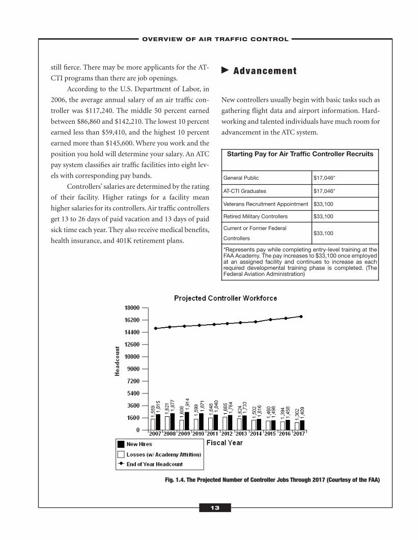
� Advancement
New controllers usually begin with basic tasks such as
gathering flight data and airport information. Hard-
working and talented individuals havemuch room for
advancement in the ATC system.
Fig. 1.4. The Projected Number of Controller Jobs Through 2017 (Courtesy of the FAA)
13
–OVERVIEW OF AIR TRAFFIC CONTROL–
Starting Pay for Air Traffic Controller Recruits
General Public $17,046*
AT-CTI Graduates $17,046*
Veterans Recruitment Appointment $33,100
Retired Military Controllers $33,100
Current or Former Federal
Controllers$33,100
*Represents pay while completing entry-level training at theFAA Academy. The pay increases to $33,100 once employedat an assigned facility and continues to increase as eachrequired developmental training phase is completed. (TheFederal Aviation Administration)
ATC_2008b:Layout 1 11/24/08 1:14 PM Page 13
–OVERVIEW OF AIR TRAFFIC CONTROL–
Chapter 1 Review Quiz
1–10: Circle the correct answer.
1. What act required the aviation industry toimprove and maintain safety standards for
aircraft?
a. Federal Aviation Act
b. Air Commerce Act
c. Air Traffic Control Act
d. National Airspace System Act
2. The United States maintains the most complexaviation system in the world, which includes an
enormous network of people, facilities, and tech-
nology, known as the
a. Air Traffic Collegiate Training Initiative (AT-
CTI).
b. William J. Hughes Technical Center
(WJHTC).
c. Federal Aviation Administration (FAA).
d. National Airspace System (NAS).
3. Which of the following represents one of the pri-mary work environments of air traffic
controllers?
a. air traffic control tower (ATCT)
b. air route traffic control center (ARTCC)
c. terminal radar approach control facility
(TRACON)
d. all of the above
4. When a TRACON departure controller passesthe responsibility of monitoring an aircraft to a
controller in an ARTCC, it is known as
a. a hand-off.
b. en route control.
c. a sector.
d. local control.
5. Which of the following is a responsibility of acontroller specializing in local control (LC)?
a. collecting, tabulating, and storing daily
records
b. controlling vehicles on the airport movement
area
c. receiving and relaying pilot reports (PIREPs)
d. forwarding departure times to air route traffic
control centers (ARTCCs)
6. Which part of the Air Traffic Selection andTraining Test (AT-SAT) assesses the personal
attributes of applicants?
a. Scan Test
b. Experience Questionnaire
c. Analogy Test
d. Medical Exam
7. Which part of the Air Traffic Selection andTraining Test (AT-SAT) simulates a radar screen
and tests an applicant’s ability to multitask?
a. Air Traffic Scenarios Test
b. Dial Reading Test
c. Letter Factory Test
d. Experience Questionnaire
8. Air traffic controllers who monitor aircraft in theairspace around an air route traffic control cen-
ter (ARTCC) are called
a. terminal controllers.
b. arrival controllers.
c. en route center controllers.
d. flight service specialists.
14
ATC_2008b:Layout 1 11/24/08 1:14 PM Page 14
9. The partnership between the Federal AviationAdministration (FAA) and colleges or universi-
ties that offer two- or four-year air traffic control
(ATC) programs is called the
a. Air Traffic Control Collegiate Training
Initiative (AT-CTI).
b. Air Traffic Selection and Training Test (AT-
SAT).
c. Air Traffic Basics (ATB) Course.
d. Federal Aviation Administration (FAA)
Academy.
10. At what age do most air traffic controllers facemandatory retirement?
a. 31
b. 40
c. 56
d. 65
Check your answers on page 287.
15
–OVERVIEW OF AIR TRAFFIC CONTROL–
ATC_2008b:Layout 1 11/24/08 1:14 PM Page 15

ATC_2008b:Layout 1 11/24/08 1:14 PM Page 16
You learned in Chapter 1 that controllers are part of an air traffic control (ATC) system, which is a
vast network of people and equipment whose purpose is to ensure the safety of aircraft and pas-
sengers. Airports and airspace are also part of this ATC system, and successful navigation and com-
munication are essential to its operation.
� Navigat ion
In the early days of flying, before navigation technologies were developed, pilots could only fly during the day
and in good weather. These pilots had to rely solely on their vision and constantly adjust their controls to ensure
a straight, safe flight.
Innovations in modern navigation have enabled many more planes to fly safely in the skies, even in low-
visibility conditions. Many navigation systems are available today to assist pilots. Controllers also use these sys-
tems to help pilots safely navigate their way to and from airports.
The Air TrafficControl System
CHAPTER SUMMARYPilots and controllers use modern navigational aids to maintain safe
separation between aircraft and to ensure that aircraft fly safely in and
out of airports. It is essential that pilots and controllers communicate
clearly to prevent misunderstandings that might lead to disaster.
2C H A P T E R
17
ATC_2008b:Layout 1 11/24/08 1:14 PM Page 17
Visual Flight Rules (VFR)
The phrase visual flight rules (VFR) refers to the reg-
ulations that tell pilots when they can conduct flights
using visual navigation (as opposed to using instru-
ments to navigate). An aircraft conducting flight
according to these rules is called aVFRaircraft. Recre-
ational pilots often flyVFR aircraft, as do pilots whose
electronic instruments have failed.VFR rules are based
on minimum cloud clearance and visibility require-
ments, since themain visual references forVFR are the
ground and the horizon. When pilots are following
VFR, they must use a combination of two navigation
techniques called “pilotage” and “dead reckoning.”
PilotageIn the early days of aviation, pilots used a visual navi-
gation technique called pilotage. They looked at amap
and then drew a line on themap from departure point
to destination point to chart their course, noting any
major landmarks along the way. If the pilot passed
these landmarks while flying, then he or she was on
course. If the pilot failed to pass these landmarks or
passed landmarks that were not factored into the orig-
inal plan, he or she was off course and possibly lost.
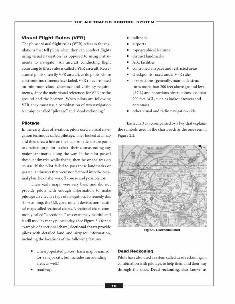
These early maps were very basic and did not
provide pilots with enough information to make
pilotage an effective type of navigation. To remedy this
shortcoming, the U.S. government devised aeronauti-
calmaps called sectional charts.A sectional chart, com-
monly called “a sectional,” was extremely helpful and
is still used bymany pilots today. (See Figure 2.1 for an
example of a sectional chart.) Sectional charts provide
pilots with detailed land and airspace information,
including the locations of the following features:
� cities/populated places (Each map is named
for a major city, but includes surrounding
areas as well.)� roadways
� railroads� airports� topographical features� distinct landmarks� ATC facilities� controlled airspace and restricted areas� checkpoints (used under VFR rules)� obstructions (generally, manmade struc-
tures more than 200 feet above ground level
[AGL] and hazardous obstructions less than
200 feet AGL, such as lookout towers and
antennas)� other visual and radio navigation aids
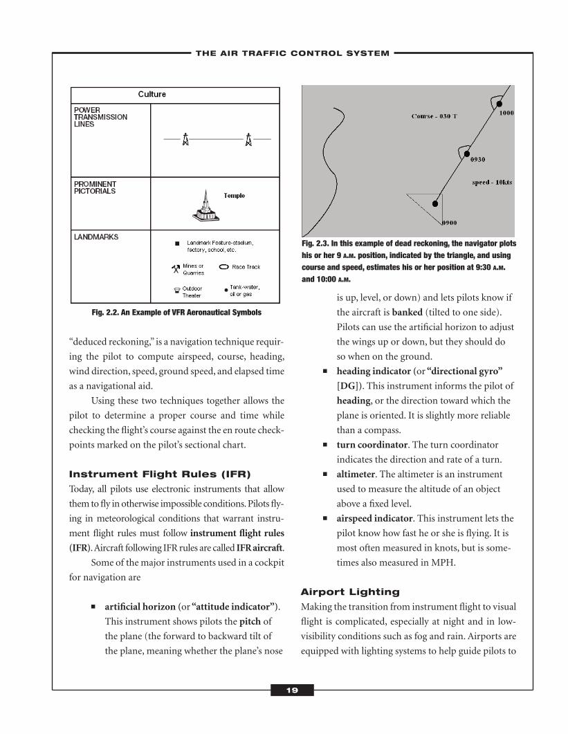
Each chart is accompanied by a key that explains
the symbols used in the chart, such as the one seen in
Figure 2.2.
Fig 2.1. A Sectional Chart
Dead ReckoningPilots have also used a system called dead reckoning, in
combination with pilotage, to help them find their way
through the skies. Dead reckoning, also known as
–THE AIR TRAFFIC CONTROL SYSTEM–
18
ATC_2008b:Layout 1 11/24/08 1:14 PM Page 18
“deduced reckoning,” is a navigation technique requir-
ing the pilot to compute airspeed, course, heading,
wind direction, speed, ground speed, and elapsed time
as a navigational aid.
Using these two techniques together allows the
pilot to determine a proper course and time while
checking the flight’s course against the en route check-
points marked on the pilot’s sectional chart.
Instrument Flight Rules (IFR)
Today, all pilots use electronic instruments that allow
them tofly in otherwise impossible conditions.Pilots fly-
ing in meteorological conditions that warrant instru-
ment flight rules must follow instrument flight rules
(IFR).Aircraft following IFR rules are called IFRaircraft.
Some of themajor instruments used in a cockpit
for navigation are
� artificial horizon (or“attitude indicator”).
This instrument shows pilots the pitch of
the plane (the forward to backward tilt of
the plane, meaning whether the plane’s nose
is up, level, or down) and lets pilots know if
the aircraft is banked (tilted to one side).
Pilots can use the artificial horizon to adjust
the wings up or down, but they should do
so when on the ground.� heading indicator (or“directional gyro”
[DG]). This instrument informs the pilot of
heading, or the direction toward which the
plane is oriented. It is slightly more reliable
than a compass.� turn coordinator. The turn coordinator
indicates the direction and rate of a turn.� altimeter. The altimeter is an instrument
used to measure the altitude of an object
above a fixed level.� airspeed indicator. This instrument lets the
pilot know how fast he or she is flying. It is
most often measured in knots, but is some-
times also measured in MPH.
Airport Lighting
Making the transition from instrument flight to visual
flight is complicated, especially at night and in low-
visibility conditions such as fog and rain. Airports are
equipped with lighting systems to help guide pilots to
Fig. 2.2. An Example of VFR Aeronautical Symbols
Fig. 2.3. In this example of dead reckoning, the navigator plotshis or her 9 A.M. position, indicated by the triangle, and usingcourse and speed, estimates his or her position at 9:30 A.M.and 10:00 A.M.
–THE AIR TRAFFIC CONTROL SYSTEM–
19
ATC_2008b:Layout 1 11/24/08 1:14 PM Page 19
the runway, so they can safely land their aircraft. The
type of lighting system used depends on the opera-
tional requirements of the airport and runway.
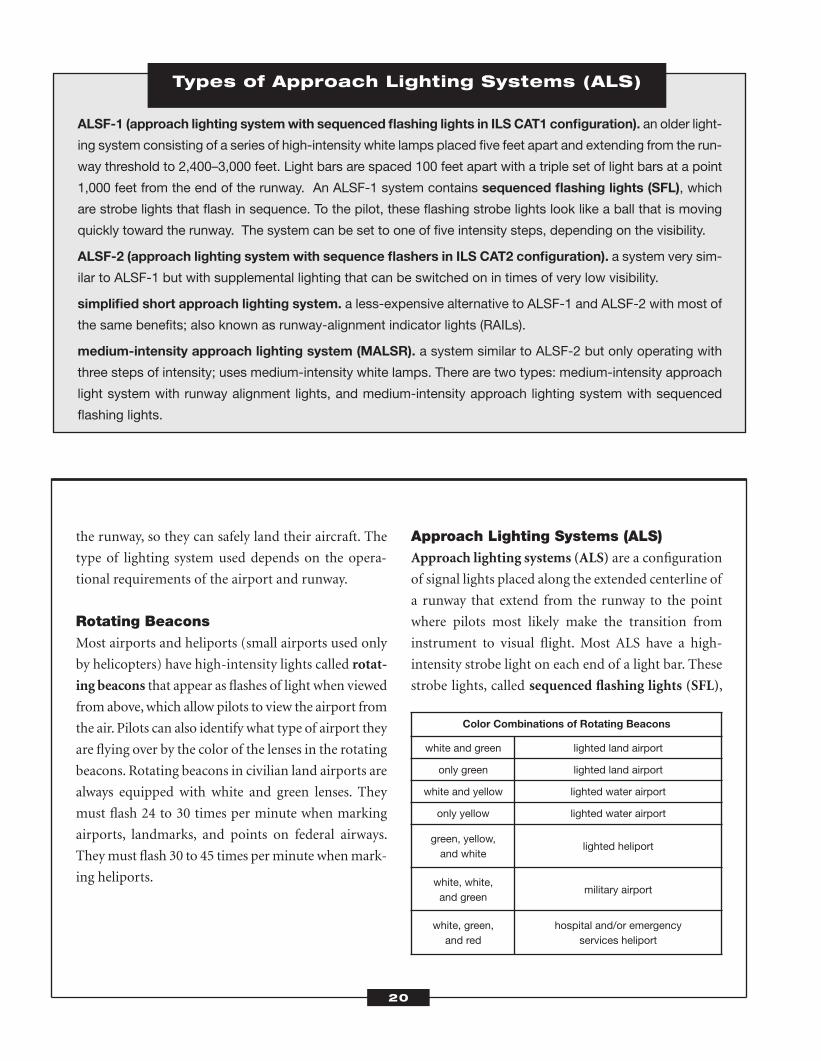
Rotating BeaconsMost airports and heliports (small airports used only
by helicopters) have high-intensity lights called rotat-
ing beacons that appear as flashes of light when viewed
from above,which allow pilots to view the airport from
the air. Pilots can also identify what type of airport they
are flying over by the color of the lenses in the rotating
beacons. Rotating beacons in civilian land airports are
always equipped with white and green lenses. They
must flash 24 to 30 times per minute when marking
airports, landmarks, and points on federal airways.
Theymust flash 30 to 45 times perminute whenmark-
ing heliports.
Approach Lighting Systems (ALS)Approach lighting systems (ALS) are a configuration
of signal lights placed along the extended centerline of
a runway that extend from the runway to the point
where pilots most likely make the transition from
instrument to visual flight. Most ALS have a high-
intensity strobe light on each end of a light bar. These
strobe lights, called sequenced flashing lights (SFL),
Types of Approach Lighting Systems (ALS)
ALSF-1 (approach lighting systemwith sequenced flashing lights in ILS CAT1 configuration). an older light-
ing system consisting of a series of high-intensity white lamps placed five feet apart and extending from the run-
way threshold to 2,400–3,000 feet. Light bars are spaced 100 feet apart with a triple set of light bars at a point
1,000 feet from the end of the runway. An ALSF-1 system contains sequenced flashing lights (SFL), which
are strobe lights that flash in sequence. To the pilot, these flashing strobe lights look like a ball that is moving
quickly toward the runway. The system can be set to one of five intensity steps, depending on the visibility.
ALSF-2 (approach lighting system with sequence flashers in ILS CAT2 configuration). a system very sim-
ilar to ALSF-1 but with supplemental lighting that can be switched on in times of very low visibility.
simplified short approach lighting system. a less-expensive alternative to ALSF-1 and ALSF-2 with most of
the same benefits; also known as runway-alignment indicator lights (RAILs).
medium-intensity approach lighting system (MALSR). a system similar to ALSF-2 but only operating with
three steps of intensity; uses medium-intensity white lamps. There are two types: medium-intensity approach
light system with runway alignment lights, and medium-intensity approach lighting system with sequenced
flashing lights.
20
Color Combinations of Rotating Beacons
white and green lighted land airport
only green lighted land airport
white and yellow lighted water airport
only yellow lighted water airport
green, yellow,and white
lighted heliport
white, white,and green
military airport
white, green,and red
hospital and/or emergencyservices heliport
ATC_2008b:Layout 1 11/24/08 1:14 PM Page 20
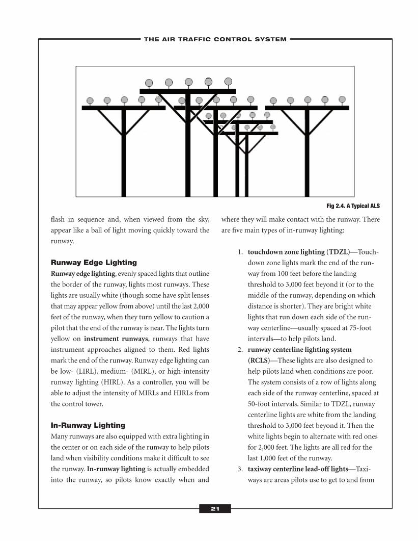
flash in sequence and, when viewed from the sky,
appear like a ball of light moving quickly toward the
runway.
Runway Edge LightingRunway edge lighting, evenly spaced lights that outline
the border of the runway, lights most runways. These
lights are usually white (though some have split lenses
thatmay appear yellow from above) until the last 2,000
feet of the runway, when they turn yellow to caution a
pilot that the end of the runway is near. The lights turn
yellow on instrument runways, runways that have
instrument approaches aligned to them. Red lights
mark the end of the runway. Runway edge lighting can
be low- (LIRL), medium- (MIRL), or high-intensity
runway lighting (HIRL). As a controller, you will be
able to adjust the intensity of MIRLs and HIRLs from
the control tower.
In-Runway LightingMany runways are also equipped with extra lighting in
the center or on each side of the runway to help pilots
land when visibility conditions make it difficult to see
the runway. In-runway lighting is actually embedded
into the runway, so pilots know exactly when and
where they will make contact with the runway. There
are five main types of in-runway lighting:
1. touchdown zone lighting (TDZL)—Touch-
down zone lights mark the end of the run-
way from 100 feet before the landing
threshold to 3,000 feet beyond it (or to the
middle of the runway, depending on which
distance is shorter). They are bright white
lights that run down each side of the run-
way centerline—usually spaced at 75-foot
intervals—to help pilots land.
2. runway centerline lighting system
(RCLS)—These lights are also designed to
help pilots land when conditions are poor.
The system consists of a row of lights along
each side of the runway centerline, spaced at
50-foot intervals. Similar to TDZL, runway
centerline lights are white from the landing
threshold to 3,000 feet beyond it. Then the
white lights begin to alternate with red ones
for 2,000 feet. The lights are all red for the
last 1,000 feet of the runway.
3. taxiway centerline lead-off lights—Taxi-
ways are areas pilots use to get to and from
–THE AIR TRAFFIC CONTROL SYSTEM–
21
Fig 2.4. A Typical ALS
ATC_2008b:Layout 1 11/24/08 1:14 PM Page 21
the runway. Lead-off lights help pilots see as
they leave the runway. They are usually
alternating green and yellow lights that let
pilots know when they are close to the run-
way or are approaching the components of
the instrument landing system/microwave
landing system (the ground-based radio sys-
tem involving the use of radio beams or
microwave beams to help guide pilots in for
landing during the final approach) critical
area.
4. taxiway centerline lead-on lights—These
lights guide pilots onto the runway. They are
also yellow and green to let pilots know that
they are close to the runway or are
approaching the components of the instru-
ment landing system/microwave landing
system critical area. They are actually the
same lights that are used as lead-off lights.
Each light is two-sided (“bidirectional”) and
emits a color in each direction.
5. land and hold short lights—Sometimes
when airports and runways are crowded,
pilots will not be able to taxi to their
intended destination right away.When
pilots must land and wait (“hold short”)
before entering an intersecting runway,
ATCs turn on the land and hold short lights,
which are a row of bright, pulsing, white
lights. Hold short lights, combined with
hold short instructions from a controller, let
the pilot know he or she will have to wait.
� Navigat ion Systems andFaci l i t ies
The Federal Aviation Administration (FAA) owns and
operates many navigation facilities, and it has the
authority to control how other navigation facilities are
established, operated, andmaintained.Non-FAA facil-
ities are owned by private organizations, the military,
state governments, and foreign governments. All nav-
igation facilities—as well as airports, heliports,weather
data sources, and other flying-related information—
are listed in the U.S.Airport/Facility Directory (A/FD).
Though the A/FD was traditionally only available in a
seven-volume book set, you can now find some of the
information online at the FAA Aviation System Stan-
dards (AVN)Web site (www.avn.faa.gov).
When low-visibility factors prevent a pilot from
seeing clearly, the potential for danger always exists.
Electronic navigation methods have been created to
help pilots find their way through unfriendly skies.
Four-Course Radio Range
The four-course radio range, which came into use in
1929, was the earliest navigation aid. It consisted of a
set of towers that transmitted a radio frequency along
federal airways. These signals guided pilots through
bad weather and to their destination by constantly
transmitting the Morse Code signals for the letters A
and N. The two looped transmissions overlapped at
certain points, which produced a clear signal. The sig-
nal, in turn, produced an on-course leg for pilots to fol-
low. The four-course radio system has some problems,
however. Radio transmissions sometimes bounced off
mountainsides, tricking pilots into thinking that they
were on course when they were not.
Marker Beacons
Marker beacons are low-powered radio beacons. Each
marker beacon has its own distinctive tone that a pilot
flying directly overhead can receive. By identifying the
beacon’s tone, the pilot can tell which beacon he or she
has just flown over, and then use this information to
determine the aircraft’s position. Marker beacons do
–THE AIR TRAFFIC CONTROL SYSTEM–
22
ATC_2008b:Layout 1 11/24/08 1:14 PM Page 22
not help pilots who have flown off course, however.
They are still in use in some locations.
Nondirectional Radio Beacon
(NDB)
A nondirectional radio beacon (NDB) is an older,
basic communication and navigation technology
that allows pilots to determine their position in rela-
tion to the “home” position of the NDB. It transmits
a low-frequency signal (190 to 1750 kHz) in every
direction, and the signal is picked up by the airplane’s
direction finder (DF). In the past, pilots had to rotate
the antenna by hand to pick up the signal. The pilot
would then use a magnetic compass and the NDB
receiver to figure out the plane’s bearing (the line of
direction along which the aircraft is traveling) from
the NDB. If the pilot could figure out the bearing
from two NDBs, then the pilot could plot the plane’s
precise location. Then, if the pilot wanted to head
toward the NDB, he or she could turn the aircraft so
that it directly faced the NDB, readjusting the head-
ing as necessary so that the NDB stayed right in front
of the aircraft (a technique called homing). While
NDBs are still in use, they are being phased out.
Automatic Direction Finders
(ADFs)
Automatic direction finders (ADFs) are also an older
type of navigation aid that is used today as a backup
system in VFR aircraft. ADFs automatically calculate
the aircraft’s bearing to the NDB. ADFs can produce
false information during storms or if there is static,
however, which is why it is important for pilots to con-
tinually monitor the NDB’s identification. A system
that combines a radio beacon and instrument landing
system (ILS) markers is called a compass locator.
VHF Omnidirectional Range (VOR)
The VHF omnidirectional range (VOR) is a great
improvement over previous systems. VORs are the
main components of the national airways structure
that exists today.VORs are ground-based systems that
operate in the 108.0 to 117.95 MHz frequency and are
omnidirectional, which means they transmit many
signals in all directions.VORs give pilotsmany courses,
called radials, from which to choose between ground
stations. VORs provide only bearing (or azimuth)
information, however, and do not provide distance
information.
Distance Measuring Equipment
(DME)
Distance measurement equipment (DME) measures
an aircraft’s location by measuring its distance to the
closest ground-based station. The aircraft sends out a
signal that is received by the nearest ground-based sta-
tion, which then returns the signal to the aircraft. The
time that it takes for the signal to return to the aircraft
is used to calculate the aircraft’s distance from the sta-
tion, and therefore, its location.
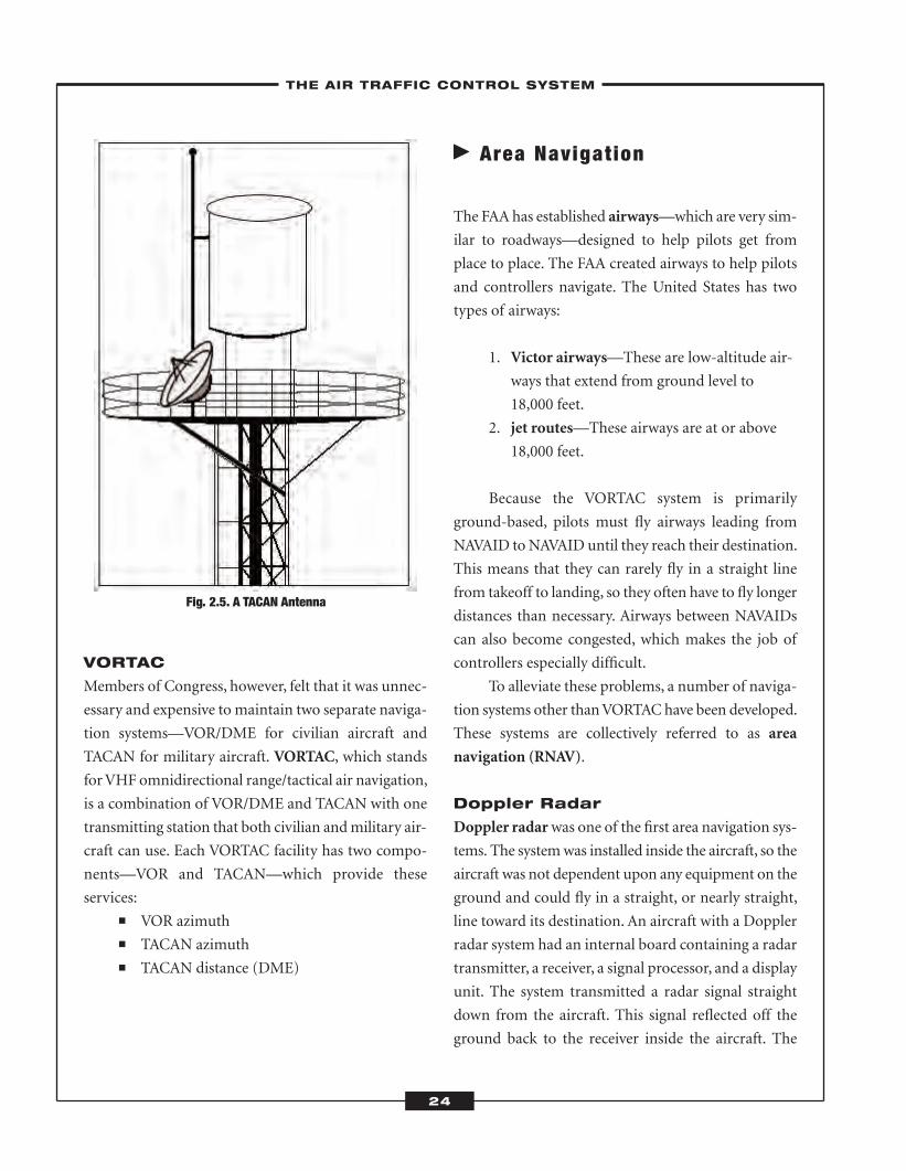
Tactical Air Navigation (TACAN)
TheDepartment of Defense considered theVOR/DME
(distance measuring equipment) systems unsuitable
for military and naval forces, so it created the tactical
air navigation (TACAN).A TACAN is smaller and eas-
ier to install than a VOR. During operation, the
TACAN equipment on the aircraft, called the inter-
rogator, transmits a coded signal to a TACAN station
on the ground, called the transponder. The transpon-
der replies in code and the interrogator decodes the
message. A TACAN can display bearing and distance
information to the pilot.
–THE AIR TRAFFIC CONTROL SYSTEM–
23
ATC_2008b:Layout 1 11/24/08 1:14 PM Page 23
VORTAC
Members of Congress, however, felt that it was unnec-
essary and expensive to maintain two separate naviga-
tion systems—VOR/DME for civilian aircraft and
TACAN for military aircraft. VORTAC, which stands
forVHF omnidirectional range/tactical air navigation,
is a combination of VOR/DME and TACAN with one
transmitting station that both civilian andmilitary air-
craft can use. Each VORTAC facility has two compo-
nents—VOR and TACAN—which provide these
services:� VOR azimuth� TACAN azimuth� TACAN distance (DME)
� Area Navigat ion
The FAA has established airways—which are very sim-
ilar to roadways—designed to help pilots get from
place to place. The FAA created airways to help pilots
and controllers navigate. The United States has two
types of airways:
1. Victor airways—These are low-altitude air-
ways that extend from ground level to
18,000 feet.
2. jet routes—These airways are at or above
18,000 feet.
Because the VORTAC system is primarily
ground-based, pilots must fly airways leading from
NAVAID toNAVAID until they reach their destination.
This means that they can rarely fly in a straight line
from takeoff to landing, so they often have to fly longer
distances than necessary. Airways between NAVAIDs
can also become congested, which makes the job of
controllers especially difficult.
To alleviate these problems, a number of naviga-
tion systems other thanVORTAChave been developed.
These systems are collectively referred to as area
navigation (RNAV).
Doppler Radar
Doppler radarwas one of the first area navigation sys-
tems. The systemwas installed inside the aircraft, so the
aircraft was not dependent upon any equipment on the
ground and could fly in a straight, or nearly straight,
line toward its destination. An aircraft with a Doppler
radar system had an internal board containing a radar
transmitter, a receiver, a signal processor, and a display
unit. The system transmitted a radar signal straight
down from the aircraft. This signal reflected off the
ground back to the receiver inside the aircraft. The
–THE AIR TRAFFIC CONTROL SYSTEM–
24
Fig. 2.5. A TACAN Antenna
ATC_2008b:Layout 1 11/24/08 1:14 PM Page 24
signal processor then compared the frequency of the
transmitted signal with the one returned to the aircraft.
This process repeated continually as long as the aircraft
remained in the air.
Pilots could use the information—the change in
signal—to guide them toward their destination.
Because the earth’s surface varies from place to place,
the frequency of the signal changed depending on the
earth under the aircraft. While Doppler radar helped
pilots determine their location, it did not give the exact
location. For this reason, it has been replaced by more
accurate types of area navigation.
Long-Range Navigation
(LORAN-C)
Long-range navigation (LORAN) was first developed
for maritime use. Because of this, its stations are
located primarily around the Great Lakes and along
U.S. coastlines and are controlled by the U.S. Coast
Guard. LORAN is a hyperbolic navigation system,
which differs from VORTAC (a rho-theta navigation
system). A hyperbolic navigation system produces
hyperbolic lines of position by measuring the differ-
ence in the reception time of radio signals emitted
from the aircraft. In a rho-theta navigation system, the
signals are emitted from a facility.
The current version of LORAN in use is LORAN-
C. With LORAN-C, a computer quickly plots the
hyperbolic lines to help pilots determine the position
of their aircraft. While LORAN-C is a fairly accurate
area navigation system, it often has technical problems,
which is one reason why it is quickly being replaced by
the global navigation satellite system (GNSS). LORAN-
C, however, is still used in many aircraft as a backup.
Global Navigation Satellite
System (GNSS)
Satellite-based navigation used throughout the world
is referred to as the global navigation satellite system
(GNSS). In the United States, this system is called the
global positioning system (GPS), and in Russia it is
called the Global Navigation Satellite System
(GLONASS).
GNSS is the newest and most accurate type of
area navigation. Like LORAN, it is a hyperbolic navi-
gation system that transmits hyperbolic lines.However,
GNSS uses transmitters that are on satellites, as
opposed to ground transmitters.
Global Positioning System (GPS)
The global positioning system (GPS) was created by
the U.S. Department of Defense (DoD) to provide
around-the-clock navigational services formilitary air,
ground, and sea forces. In the 1980s, however, the DoD
made the system available for civilian use. Since its
implementation, it has been widely used by civilian
aircraft.
GPS uses 24 satellites (21 active and 3 backups)
that circle the earth twice a day in a precise orbit and
transmit information to Earth. GPS receivers use this
information to determine an aircraft’s precise location.
Using GPS, controllers and pilots can also gather infor-
mation on an aircraft’s speed and course, the time it
will take for it to reach its destination, and how winds
are affecting the aircraft.
GPS has some drawbacks, however. It does not
provide guidance precise enough to replace ground-
based instrument landing systems (ILSs). In order to
remedy this, the FAA is experimenting with two sys-
tems to augment, or supplement,GPS, so that it can be
used as a primary means of navigation:
1. wide area augmentation system (WAAS)—
WAAS is an extremely accurate navigation
system that is able to offer vertically guided
landing approaches in all meteorological
conditions.
–THE AIR TRAFFIC CONTROL SYSTEM–
25
ATC_2008b:Layout 1 11/24/08 1:14 PM Page 25
2. local area augmentation system (LAAS)—
While still under development, LAAS
focuses on the airport area, so it can offer
aircraft precise approach and departure
information.
� Airspace Classif icat ions
The FAA categorizes the airspace above the United
States into six classes. Different categories, or classes,
are subject to different requirements and rules of oper-
ation. Airspace is first classified into one of three broad
categories:
1. uncontrolled airspace
2. controlled airspace
3. special-use airspace
Uncontrolled Airspace
When the first planes flew in the skies, all airspace was
uncontrolled. It was up to pilots to maintain separa-
tion with other aircraft. Since early planes did not have
the navigational tools to fly in clouds, pilots also had
to navigate around them. At this time, however, there
were only a few small planes in the sky and these planes
flew slowly, so separation and navigation were not
major concerns. The situation changed as planes
became a principal means of transportation and the
skies grew more crowded.
Once ATC was needed to keep planes from col-
liding, controlled airspace was created. This airspace
was designed primarily for pilots flying IFR aircraft.
Today, nearly all airspace is controlled. The remaining
uncontrolled airspace in the United States is in unpop-
ulated areas. Pilots flying in these areas do not receive
ATC separation service even in badweather conditions.
–THE AIR TRAFFIC CONTROL SYSTEM–
26
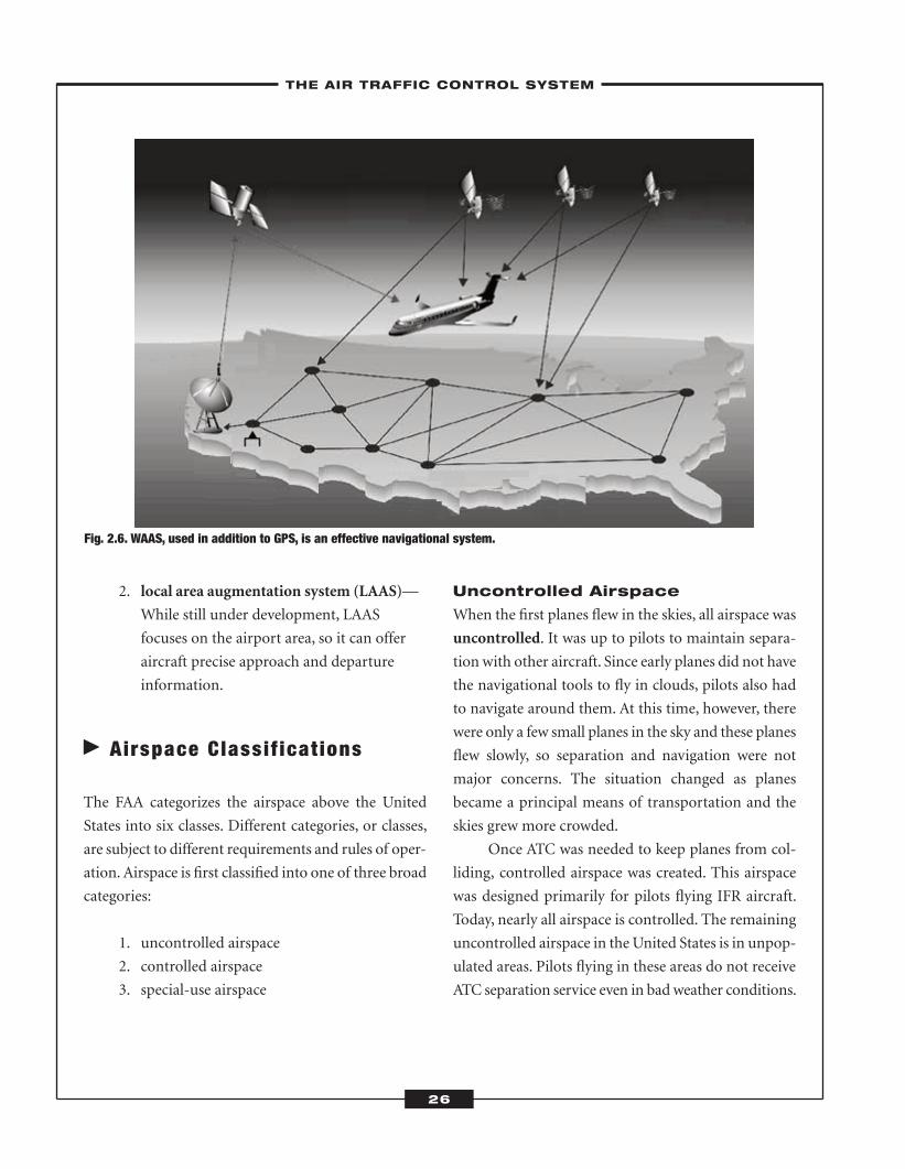
Fig. 2.6. WAAS, used in addition to GPS, is an effective navigational system.
ATC_2008b:Layout 1 11/24/08 1:14 PM Page 26
Controlled Airspace
Controlled airspace was created for pilots flying IFR
aircraft, but both pilots flying IFR and VFR aircraft in
controlled airspace receive ATC services. The level of
service, however, depends on the airspace classification.
In controlled airspace, pilots are subject to certain
qualifications, equipment requirements, and operating
procedures. Controlled airspace is divided into these
classes:
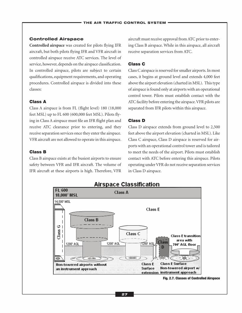
Class AClass A airspace is from FL (flight level) 180 (18,000
feet MSL) up to FL 600 (600,000 feet MSL). Pilots fly-
ing in Class A airspace must file an IFR flight plan and
receive ATC clearance prior to entering, and they
receive separation services once they enter the airspace.
VFR aircraft are not allowed to operate in this airspace.
Class BClass B airspace exists at the busiest airports to ensure
safety between VFR and IFR aircraft. The volume of
IFR aircraft at these airports is high. Therefore, VFR
aircraft must receive approval fromATCprior to enter-
ing Class B airspace.While in this airspace, all aircraft
receive separation services from ATC.
Class CClass C airspace is reserved for smaller airports. Inmost
cases, it begins at ground level and extends 4,000 feet
above the airport elevation (charted inMSL). This type
of airspace is found only at airports with an operational
control tower. Pilots must establish contact with the
ATC facility before entering the airspace.VFR pilots are
separated from IFR pilots within this airspace.
Class DClass D airspace extends from ground level to 2,500
feet above the airport elevation (charted inMSL). Like
Class C airspace, Class D airspace is reserved for air-
ports with an operational control tower and is tailored
to meet the needs of the airport. Pilots must establish
contact with ATC before entering this airspace. Pilots
operating underVFR do not receive separation services
in Class D airspace.
Fig. 2.7. Classes of Controlled Airspace
–THE AIR TRAFFIC CONTROL SYSTEM–
27
ATC_2008b:Layout 1 11/24/08 1:14 PM Page 27
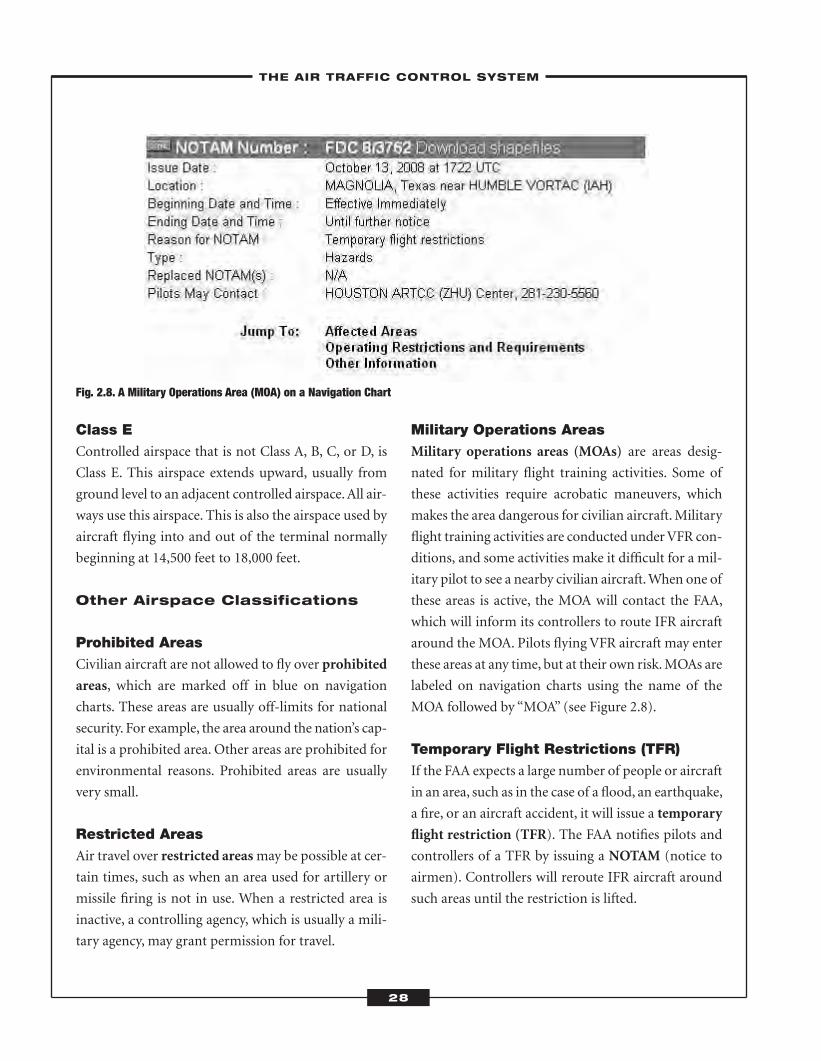
Class EControlled airspace that is not Class A, B, C, or D, is
Class E. This airspace extends upward, usually from
ground level to an adjacent controlled airspace.All air-
ways use this airspace. This is also the airspace used by
aircraft flying into and out of the terminal normally
beginning at 14,500 feet to 18,000 feet.
Other Airspace Classifications
Prohibited AreasCivilian aircraft are not allowed to fly over prohibited
areas, which are marked off in blue on navigation
charts. These areas are usually off-limits for national
security. For example, the area around the nation’s cap-
ital is a prohibited area. Other areas are prohibited for
environmental reasons. Prohibited areas are usually
very small.
Restricted AreasAir travel over restricted areasmay be possible at cer-
tain times, such as when an area used for artillery or
missile firing is not in use. When a restricted area is
inactive, a controlling agency, which is usually a mili-
tary agency, may grant permission for travel.
Military Operations AreasMilitary operations areas (MOAs) are areas desig-
nated for military flight training activities. Some of
these activities require acrobatic maneuvers, which
makes the area dangerous for civilian aircraft.Military
flight training activities are conducted underVFR con-
ditions, and some activities make it difficult for a mil-
itary pilot to see a nearby civilian aircraft.When one of
these areas is active, the MOA will contact the FAA,
which will inform its controllers to route IFR aircraft
around the MOA. Pilots flying VFR aircraft may enter
these areas at any time, but at their own risk.MOAs are
labeled on navigation charts using the name of the
MOA followed by “MOA” (see Figure 2.8).
Temporary Flight Restrictions (TFR)If the FAA expects a large number of people or aircraft
in an area, such as in the case of a flood, an earthquake,
a fire, or an aircraft accident, it will issue a temporary
flight restriction (TFR). The FAA notifies pilots and
controllers of a TFR by issuing a NOTAM (notice to
airmen). Controllers will reroute IFR aircraft around
such areas until the restriction is lifted.
Fig. 2.8. A Military Operations Area (MOA) on a Navigation Chart
–THE AIR TRAFFIC CONTROL SYSTEM–
28
ATC_2008b:Layout 1 11/24/08 1:14 PM Page 28
Warning AreaA warning area is similar to a restricted area except it
encompasses airspace over domestic or international
waters as opposed to land. A warning area extends
from 3 NM (nautical miles) beyond shore. Warning
areas are advisory areas—pilots do not have to stay out
of these areas but are alerted of possible danger. Both
IFR and VFR aircraft may fly into these areas at their
own risk. Warning areas are marked on navigational
charts with the word “WARNING.”
Alert AreasAlert areas are areas in which unusual activity, such as
pilot training, may be taking place. Both IFR andVFR
aircraft may fly into these areas without following any
special rules, but they should be alert to possible haz-
ards. Alert areas are marked on navigational charts
with the letter “A.”
� Radio Communicat ions
Controllers must communicate clearly with pilots so
that pilots have the information they need tomaintain
separation and safely operate aircraft. Any misunder-
standing between controller and pilot could result in
disaster. Controllers and pilots most often communi-
cate via two-way radio.
Frequencies
The FAA operates over 5,000 frequencies to avoid
potential conflicts and interference within radio bands.
Controllers normally use simplex communication,
which means they use a single frequency to transmit
and receive messages. This frequency might be in one
of three bands:
1. high frequency (HF)
2. very high frequency (VHF)
3. ultra-high frequency (UHF)
ATC centers most often use VHF and UHF for
routine communications with pilots of civilian aircraft.
Controllers most often useVHF to communicate with
civilian aircraft and UHF to communicate with mili-
tary aircraft. The Federal Communications Commis-
sion (FCC) carefully assigns frequencies to avoid
potential interference problems. Since there are not
enough frequencies available to give each ATC center
its own frequency, the FCC usually assigns the same
frequency to two or more ATC centers.
Operation
Within an ATC facility, each controller is assigned one
or more frequencies for communication with pilots.
Most controllers wear an assembly consisting of a
boom mike, a headset, and a push-to-talk amplifier
attached to a cord. This allows them to move around
while communicating with pilots. Controllers use the
telephone to communicate with other controllers.
They alternate between radio and telephone commu-
nication using a voice switching system.
Phraseology
Because controllers and pilots must be clear and con-
cise in their communication, they use phraseology, a
kind of jargon used by those in the aviation industry.
Controllers should use this format when communi-
cating with other controllers:
Fig. 2.9. A TFR NOTAM
–THE AIR TRAFFIC CONTROL SYSTEM–
29
ATC_2008b:Layout 1 11/24/08 1:14 PM Page 29
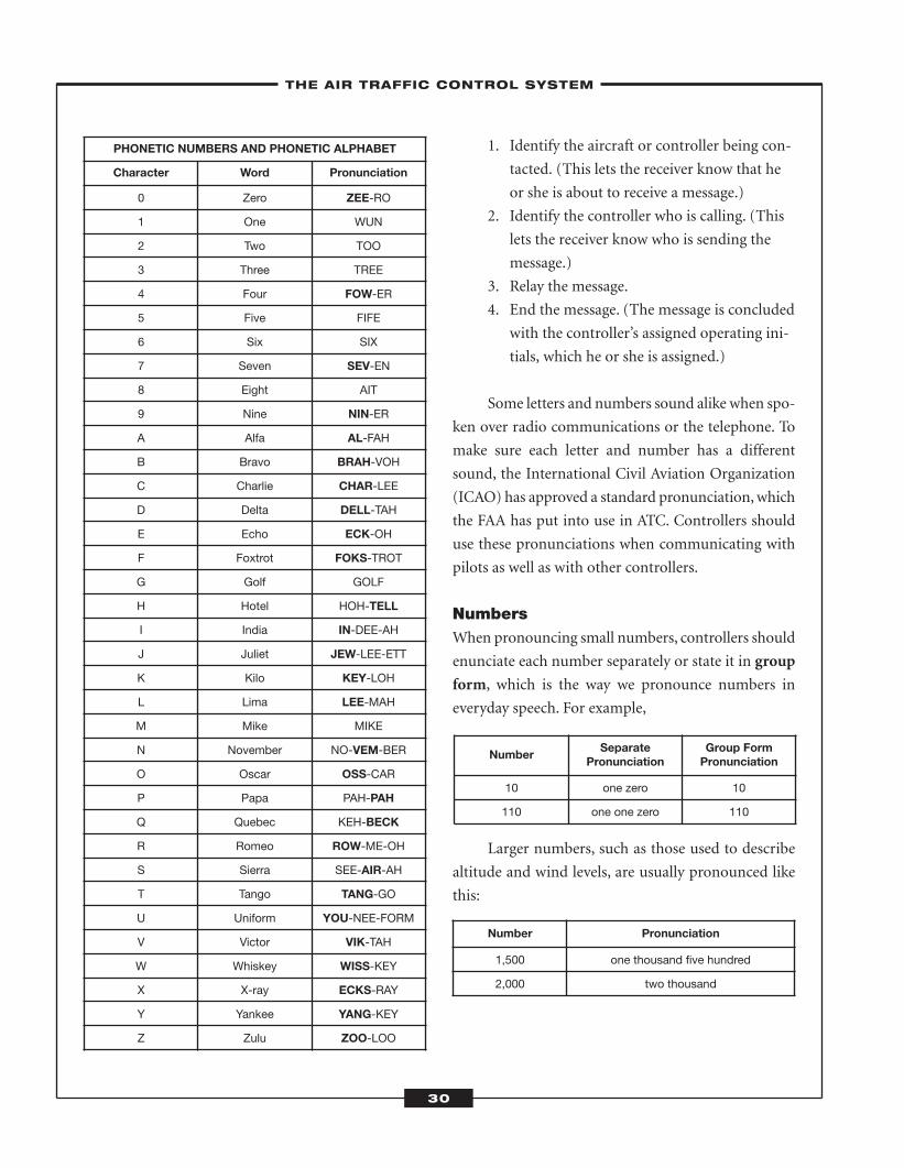
1. Identify the aircraft or controller being con-
tacted. (This lets the receiver know that he
or she is about to receive a message.)
2. Identify the controller who is calling. (This
lets the receiver know who is sending the
message.)
3. Relay the message.
4. End the message. (The message is concluded
with the controller’s assigned operating ini-
tials, which he or she is assigned.)
Some letters and numbers sound alike when spo-
ken over radio communications or the telephone. To
make sure each letter and number has a different
sound, the International Civil Aviation Organization
(ICAO) has approved a standard pronunciation,which
the FAA has put into use in ATC. Controllers should
use these pronunciations when communicating with
pilots as well as with other controllers.
NumbersWhen pronouncing small numbers, controllers should
enunciate each number separately or state it in group
form, which is the way we pronounce numbers in
everyday speech. For example,
Larger numbers, such as those used to describe
altitude and wind levels, are usually pronounced like
this:
NumberSeparate
PronunciationGroup FormPronunciation
10 one zero 10
110 one one zero 110
Number Pronunciation
1,500 one thousand five hundred
2,000 two thousand
–THE AIR TRAFFIC CONTROL SYSTEM–
30
PHONETIC NUMBERS AND PHONETIC ALPHABET
Character Word Pronunciation
0 Zero ZEE-RO
1 One WUN
2 Two TOO
3 Three TREE
4 Four FOW-ER
5 Five FIFE
6 Six SIX
7 Seven SEV-EN
8 Eight AIT
9 Nine NIN-ER
A Alfa AL-FAH
B Bravo BRAH-VOH
C Charlie CHAR-LEE
D Delta DELL-TAH
E Echo ECK-OH
F Foxtrot FOKS-TROT
G Golf GOLF
H Hotel HOH-TELL
I India IN-DEE-AH
J Juliet JEW-LEE-ETT
K Kilo KEY-LOH
L Lima LEE-MAH
M Mike MIKE
N November NO-VEM-BER
O Oscar OSS-CAR
P Papa PAH-PAH
Q Quebec KEH-BECK
R Romeo ROW-ME-OH
S Sierra SEE-AIR-AH
T Tango TANG-GO
U Uniform YOU-NEE-FORM
V Victor VIK-TAH
W Whiskey WISS-KEY
X X-ray ECKS-RAY
Y Yankee YANG-KEY
Z Zulu ZOO-LOO
ATC_2008b:Layout 1 11/24/08 1:14 PM Page 30
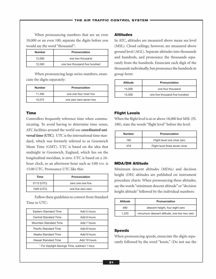
When pronouncing numbers that are an even
10,000 or an even 100, separate the digits before you
would say the word “thousand”:
When pronouncing large series numbers, enun-
ciate the digits separately:
TimeControllers frequently reference time when commu-
nicating. To avoid having to determine time zones,
ATC facilities around the world use coordinated uni-
versal time (UTC). UTC is the international time stan-
dard, which was formerly referred to as Greenwich
Mean Time (GMT). UTC is based on the idea that
midnight in Greenwich, England, which lies on the
longitudinal meridian, is zero. UTC is based on a 24-
hour clock, so an afternoon hour such as 3:00 P.M. is
15:00 UTC. Pronounce UTC like this:
Follow these guidelines to convert from Standard
Time to UTC:
AltitudesIn ATC, altitudes are measured above mean sea level
(MSL). Cloud ceilings, however, are measured above
ground level (AGL). Separate altitudes into thousands
and hundreds, and pronounce the thousands sepa-
rately from the hundreds. Enunciate each digit of the
thousands individually, but pronounce the hundreds in
group form:
Flight LevelsWhen the flight level is at or above 18,000 feetMSL (FL
180), state the words “flight level” before the level:
MDA/DH AltitudeMinimum descent altitudes (MDAs) and decision
height (DH) altitudes are published on instrument
procedure charts. When pronouncing these altitudes,
say the words“minimumdescent altitude”or“decision
height altitude” followed by the individual numbers:
SpeedsWhen pronouncing speeds, enunciate the digits sepa-
rately followed by the word “knots.” (Do not use the
Number Pronunciation
190 Flight level one niner zero
379 Flight level three seven niner
Time Pronunciation
0115 (UTC) zero one one five
1500 (UTC) one five zero zero
Eastern Standard Time Add 5 hours
Central Standard Time Add 6 hours
Mountain Standard Time Add 7 hours
Pacific Standard Time Add 8 hours
Alaska Standard Time Add 9 hours
Hawaii Standard Time Add 10 hours
* For Daylight Savings Time, subtract 1 hour.
Number Pronunciation
12,000 one two thousand
12,500 one two thousand five hundred
Number Pronunciation
11,495 one one four niner five
10,072 one zero zero seven two
Altitude Pronunciation
14,000 one four thousand
15,500 one five thousand five hundred
Altitude Pronunciation
480 descent height, four eight zero
1,220 minumum descent altitude, one two two zero
–THE AIR TRAFFIC CONTROL SYSTEM–
31
ATC_2008b:Layout 1 11/24/08 1:14 PM Page 31
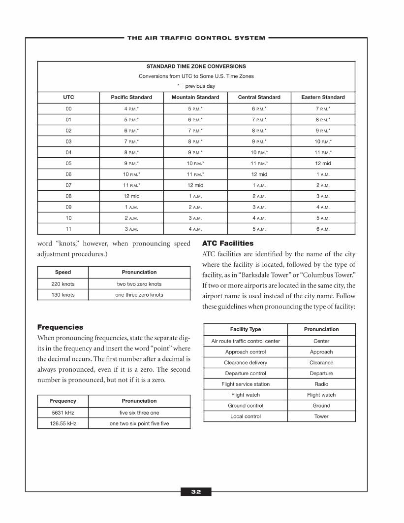
word “knots,” however, when pronouncing speed
adjustment procedures.)
FrequenciesWhen pronouncing frequencies, state the separate dig-
its in the frequency and insert the word “point”where
the decimal occurs. The first number after a decimal is
always pronounced, even if it is a zero. The second
number is pronounced, but not if it is a zero.
ATC FacilitiesATC facilities are identified by the name of the city
where the facility is located, followed by the type of
facility, as in “Barksdale Tower” or “Columbus Tower.”
If two ormore airports are located in the same city, the
airport name is used instead of the city name. Follow
these guidelines when pronouncing the type of facility:
Facility Type Pronunciation
Air route traffic control center Center
Approach control Approach
Clearance delivery Clearance
Departure control Departure
Flight service station Radio
Flight watch Flight watch
Ground control Ground
Local control Tower
–THE AIR TRAFFIC CONTROL SYSTEM–
Speed Pronunciation
220 knots two two zero knots
130 knots one three zero knots
STANDARD TIME ZONE CONVERSIONS
Conversions from UTC to Some U.S. Time Zones
* = previous day
UTC Pacific Standard Mountain Standard Central Standard Eastern Standard
00 4 P.M.* 5 P.M.* 6 P.M.* 7 P.M.*
01 5 P.M.* 6 P.M.* 7 P.M.* 8 P.M.*
02 6 P.M.* 7 P.M.* 8 P.M.* 9 P.M.*
03 7 P.M.* 8 P.M.* 9 P.M.* 10 P.M.*
04 8 P.M.* 9 P.M.* 10 P.M.* 11 P.M.*
05 9 P.M.* 10 P.M.* 11 P.M.* 12 mid
06 10 P.M.* 11 P.M.* 12 mid 1 A.M.
07 11 P.M.* 12 mid 1 A.M. 2 A.M.
08 12 mid 1 A.M. 2 A.M. 3 A.M.
09 1 A.M. 2 A.M. 3 A.M. 4 A.M.
10 2 A.M. 3 A.M. 4 A.M. 5 A.M.
11 3 A.M. 4 A.M. 5 A.M. 6 A.M.
Frequency Pronunciation
5631 kHz five six three one
126.55 kHz one two six point five five
32
ATC_2008b:Layout 1 11/24/08 1:14 PM Page 32
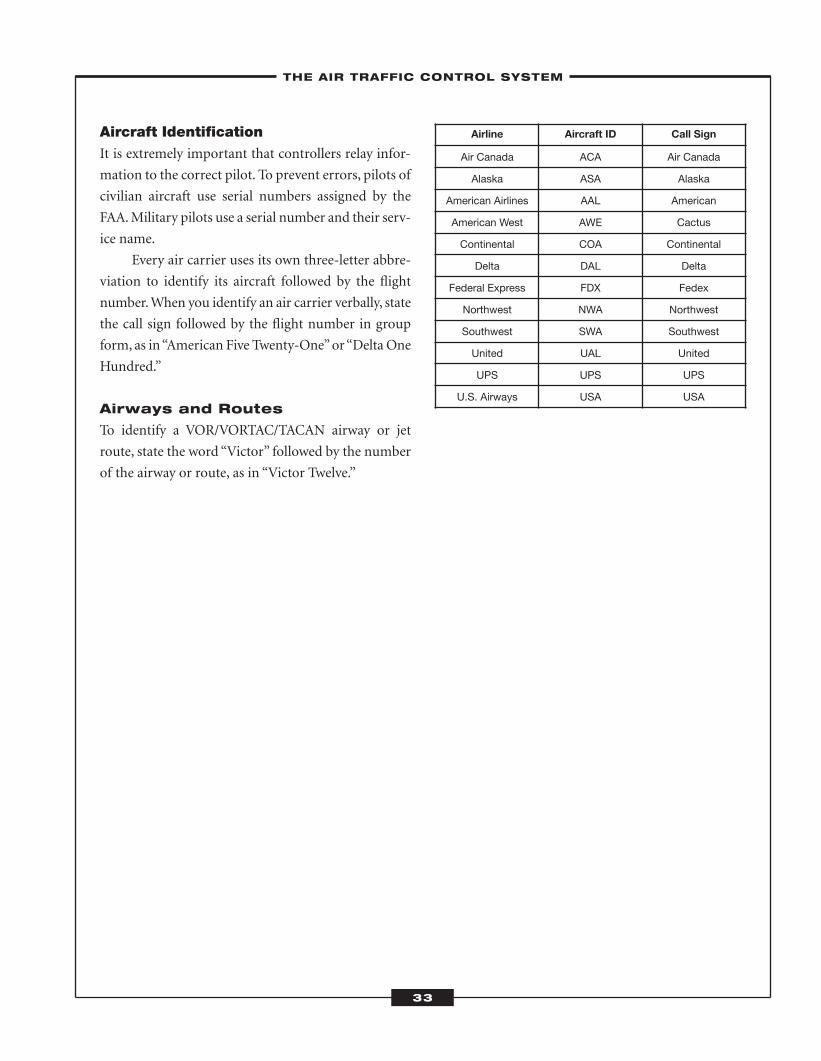
Aircraft IdentificationIt is extremely important that controllers relay infor-
mation to the correct pilot. To prevent errors, pilots of
civilian aircraft use serial numbers assigned by the
FAA.Military pilots use a serial number and their serv-
ice name.
Every air carrier uses its own three-letter abbre-
viation to identify its aircraft followed by the flight
number.When you identify an air carrier verbally, state
the call sign followed by the flight number in group
form, as in“American Five Twenty-One”or“Delta One
Hundred.”
Airways and Routes
To identify a VOR/VORTAC/TACAN airway or jet
route, state the word “Victor” followed by the number
of the airway or route, as in “Victor Twelve.”
–THE AIR TRAFFIC CONTROL SYSTEM–
Airline Aircraft ID Call Sign
Air Canada ACA Air Canada
Alaska ASA Alaska
American Airlines AAL American
American West AWE Cactus
Continental COA Continental
Delta DAL Delta
Federal Express FDX Fedex
Northwest NWA Northwest
Southwest SWA Southwest
United UAL United
UPS UPS UPS
U.S. Airways USA USA
33
ATC_2008b:Layout 1 11/24/08 1:14 PM Page 33
Chapter 2 Review Quiz
1–15: Write your answers on the lines below.
1. How should a controller pronounce the number12?
a. twelve
b. one two
c. one ten two
d. two one
2. If it is 5:00 P.M. Pacific Standard Time, what isthe UTC?
a. 00:00
b. 01:00
c. 02:00
d. 03:00
3. Which frequency do controllers use for routinecommunication with civilian aircraft?
a. UHF
b. LF
c. VHF
d. HF
4. What is the call sign for AmericanWest Airlines?a. AW
b. American
c. West
d. Cactus
5. What type of airport lighting usually has a high-intensity strobe light on a bar?
a. in-runway lighting
b. rotating beacons
c. approach lighting
d. runway edge lighting
6. Which airspace is reserved for smaller airports?a. Class C
b. Class D
c. Class E
d. Class G
7. How should a controller identify an ATC groundcontrol facility?
a. ground
b. control
c. GC
d. ground control
8. Airways above 18,000 feet are calleda. Victor airways.
b. long-range routes.
c. jet routes.
d. VORTAC airways.
9. How should a controller pronounce the number19,213?
a. one niner two one three
b. nineteen thousand two one three
c. nineteen thousand two hundred one three
d. nine thousand two hundred thirteen
10.Which airspace exists at the busiest airports?a. Class A
b. Class B
c. Class C
d. Class G
11. How should a controller pronounce a speed of230?
a. two three zero
b. two three zero knots
c. two three zero kilohertz
d. two thirty
–THE AIR TRAFFIC CONTROL SYSTEM–
34
ATC_2008b:Layout 1 11/24/08 1:14 PM Page 34
12. A pilot using electronic instruments must followa. VFR.
b. IFR.
c. pilotage.
d. dead reckoning.
13. A new civilian aircraft most likely has which nav-igation system?
a. ADF
b. TACAN
c. VOR
d. RNAV
14. A warning area is different from a restricted areabecause a warning area
a. allows air travel at certain times.
b. does not allow civilian aircraft.
c. is over water.
d. is for the military.
15. How should a controller pronounce flight level185?
a. Victor one eight five
b. flight level one eight five
c. one eight five
d. flight level one hundred eight five
Check your answers on page 287.
–THE AIR TRAFFIC CONTROL SYSTEM–
35
ATC_2008b:Layout 1 11/24/08 1:14 PM Page 35

ATC_2008b:Layout 1 11/24/08 1:14 PM Page 36
While controllers do not forecast the weather, weather conditions significantly affect aviation.
Controllers need to understand how theNationalWeather Service (NWS) communicates with
the FAA, and they need to knowwhat offices to contact and what services to access when they
need more information. Controllers must also be able to read weather reports, so they can successfully navigate
aircraft around areas with low visibility.
� Weather Forecast ing Services
The FAA and the NWS work together to detect and predict weather conditions that may interfere with avi-
ation. This partnership is necessary and important, since the FAA’s job is tomaintain safe skies and theNWS owns
most forecasting equipment, employs most meteorologists, and thus prepares the majority of official forecasts.
The NWS works with the FAA to disseminate this information to flight professionals.
Weather and AirTraffic Control
CHAPTER SUMMARYThe Storm Prediction Center (SPC), the Aviation Weather Center
(AWC), and Weather Forecasts Offices (WFOs) provide weather fore-
casts to the FAA. Controllers and pilots access these forecasts using
a Direct User Access Service (DUATS) and by contacting Flight Serv-
ice Stations (FSSs). Weather reports such as the Meteorological Avi-
ation Report (METAR) are used to create weather forecasts.
3C H A P T E R
37
ATC_2008b:Layout 1 11/24/08 1:14 PM Page 37
Three parts of the NWS work directly with
the FAA:
1. Storm Prediction Center (SPC)
2. AviationWeather Center (AWC)
3. Weather Forecast Offices (WFOs)
Storm Prediction Center (SPC)
Located in Norman, Oklahoma, the Storm Prediction
Center (SPC) is the part of the NWS that watches for
severe weather for the safety of the public. The SPC
does not target its forecasts toward aviation.
SPC forecasters are divided into three types: (1)
lead forecasters, who coordinate all efforts and issue
Tornado and Severe Thunderstorm Watches, (2)
mesoscale forecasters, who examine dangerous
weather that may occur within the next six hours over
an area of about 35,000 square miles (roughly half the
size of the state of Iowa), and (3) outlook forecasters,
who prepare forecasts of severe thunderstorm activity
that may occur within the next two days. Together
these forecasters issue storm watches, but not storm
warnings. They also issue the convective outlook, a
nationwide forecast of all convective activity and thun-
derstorms over a 24-hour period.
Aviation Weather Center (AWC)
Located in Kansas City, Missouri, Aviation Weather
Center (AWC) also issues severe weather warnings, but
unlike SPC, it focuses specifically on the interests of
aviation. In particular,AWC issues warnings, forecasts,
and analyses of hazardous weather thatmay occur over
the next two days. AWC warns in-flight aircraft and
controllers of severe weather conditions. AWC also
maintains the significant wind prognostic chart and
the tropopause wind and wind-shear charts, as well as
the volcanic ash transport and dispersion charts,which
portray the movement of volcanic ash through the
atmosphere as predicted by computer models.
Weather Forecast Offices (WFOs)
Weather Forecast Offices (WFOs) are separated into
six geographic regions: Eastern, Southern, Central,
Western, Alaskan, and Pacific. Within each region are
a number of offices located in major cities. EachWFO
office issues meteorological forecasts for the area for
Dangerous Volcanic Ash Clouds
Over the past 15 years, more than 80 aircraft have reported dangerous encounters with volcanic ash clouds,
which may cover more than 100,000 square miles downwind from an erupting volcano.
In seven of these encounters, the aircraft suffered severe power loss and nearly crashed. Volcanic ash
coats fuel nozzles, which creates sparks and causes a sudden loss of power. Sharp fragments within the clouds
also scratch forward-facing aircraft surfaces, such as the radar cone, and can even scratch the cockpit win-
dows badly enough to impair visibility. KLM Flight 867 encountered a cloud from the Redoubt Volcano in Alaska.
The aircraft lost power in all four engines and fell for five minutes—descending more than two miles—before
pilots were able to restart the engines and land safely. The plane required $80 million in repairs, including the
replacement of all four engines.
Volcanic ash transport and dispersion charts help pilots stay away from these harmful clouds, which are
difficult to distinguish from weather-related clouds.
38
ATC_2008b:Layout 1 11/24/08 1:14 PM Page 38
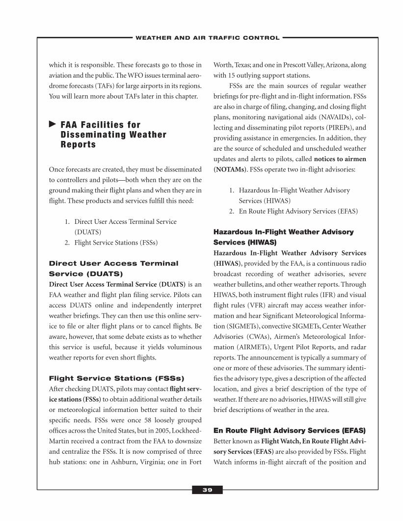
which it is responsible. These forecasts go to those in
aviation and the public. TheWFO issues terminal aero-
drome forecasts (TAFs) for large airports in its regions.
You will learn more about TAFs later in this chapter.
� FAA Faci l i t ies forDisseminat ing WeatherReports
Once forecasts are created, they must be disseminated
to controllers and pilots—both when they are on the
groundmaking their flight plans and when they are in
flight. These products and services fulfill this need:
1. Direct User Access Terminal Service
(DUATS)
2. Flight Service Stations (FSSs)
Direct User Access Terminal
Service (DUATS)
Direct User Access Terminal Service (DUATS) is an
FAA weather and flight plan filing service. Pilots can
access DUATS online and independently interpret
weather briefings. They can then use this online serv-
ice to file or alter flight plans or to cancel flights. Be
aware, however, that some debate exists as to whether
this service is useful, because it yields voluminous
weather reports for even short flights.
Flight Service Stations (FSSs)
After checking DUATS, pilots may contact flight serv-
ice stations (FSSs) to obtain additional weather details
or meteorological information better suited to their
specific needs. FSSs were once 58 loosely grouped
offices across the United States, but in 2005, Lockheed-
Martin received a contract from the FAA to downsize
and centralize the FSSs. It is now comprised of three
hub stations: one in Ashburn, Virginia; one in Fort
Worth, Texas; and one in PrescottValley,Arizona, along
with 15 outlying support stations.
FSSs are the main sources of regular weather
briefings for pre-flight and in-flight information. FSSs
are also in charge of filing, changing, and closing flight
plans, monitoring navigational aids (NAVAIDs), col-
lecting and disseminating pilot reports (PIREPs), and
providing assistance in emergencies. In addition, they
are the source of scheduled and unscheduled weather
updates and alerts to pilots, called notices to airmen
(NOTAMs). FSSs operate two in-flight advisories:
1. Hazardous In-Flight Weather Advisory
Services (HIWAS)
2. En Route Flight Advisory Services (EFAS)
Hazardous In-Flight Weather AdvisoryServices (HIWAS)Hazardous In-Flight Weather Advisory Services
(HIWAS), provided by the FAA, is a continuous radio
broadcast recording of weather advisories, severe
weather bulletins, and other weather reports. Through
HIWAS, both instrument flight rules (IFR) and visual
flight rules (VFR) aircraft may access weather infor-
mation and hear Significant Meteorological Informa-
tion (SIGMETs), convective SIGMETs,CenterWeather
Advisories (CWAs), Airmen’s Meteorological Infor-
mation (AIRMETs), Urgent Pilot Reports, and radar
reports. The announcement is typically a summary of
one or more of these advisories. The summary identi-
fies the advisory type, gives a description of the affected
location, and gives a brief description of the type of
weather. If there are no advisories,HIWASwill still give
brief descriptions of weather in the area.
En Route Flight Advisory Services (EFAS)Better known as FlightWatch, En Route Flight Advi-
sory Services (EFAS) are also provided by FSSs. Flight
Watch informs in-flight aircraft of the position and
–WEATHER AND AIR TRAFFIC CONTROL–
39
ATC_2008b:Layout 1 11/24/08 1:14 PM Page 39
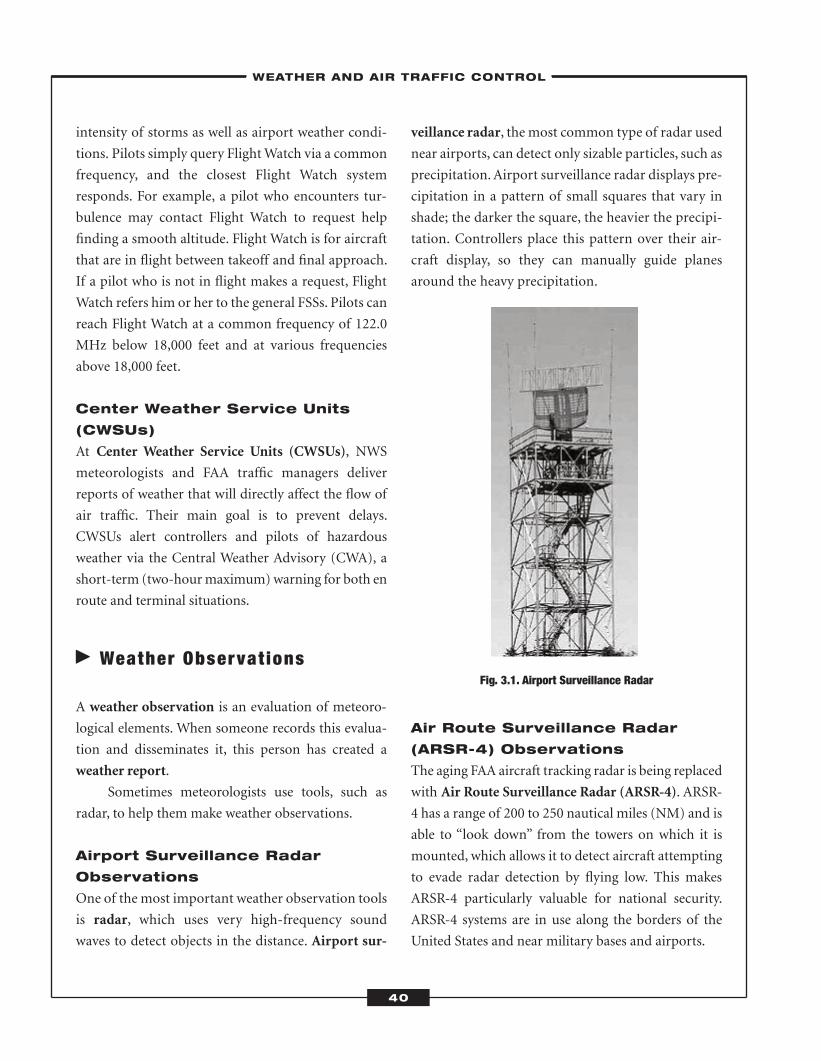
intensity of storms as well as airport weather condi-
tions. Pilots simply query FlightWatch via a common
frequency, and the closest Flight Watch system
responds. For example, a pilot who encounters tur-
bulence may contact Flight Watch to request help
finding a smooth altitude. Flight Watch is for aircraft
that are in flight between takeoff and final approach.
If a pilot who is not in flight makes a request, Flight
Watch refers him or her to the general FSSs. Pilots can
reach Flight Watch at a common frequency of 122.0
MHz below 18,000 feet and at various frequencies
above 18,000 feet.
Center Weather Service Units
(CWSUs)
At Center Weather Service Units (CWSUs), NWS
meteorologists and FAA traffic managers deliver
reports of weather that will directly affect the flow of
air traffic. Their main goal is to prevent delays.
CWSUs alert controllers and pilots of hazardous
weather via the Central Weather Advisory (CWA), a
short-term (two-hourmaximum)warning for both en
route and terminal situations.
� Weather Observat ions
A weather observation is an evaluation of meteoro-
logical elements. When someone records this evalua-
tion and disseminates it, this person has created a
weather report.
Sometimes meteorologists use tools, such as
radar, to help them make weather observations.
Airport Surveillance Radar
Observations
One of the most important weather observation tools
is radar, which uses very high-frequency sound
waves to detect objects in the distance. Airport sur-
veillance radar, the most common type of radar used
near airports, can detect only sizable particles, such as
precipitation.Airport surveillance radar displays pre-
cipitation in a pattern of small squares that vary in
shade; the darker the square, the heavier the precipi-
tation. Controllers place this pattern over their air-
craft display, so they can manually guide planes
around the heavy precipitation.
Fig. 3.1. Airport Surveillance Radar
Air Route Surveillance Radar
(ARSR-4) Observations
The aging FAA aircraft tracking radar is being replaced
with Air Route Surveillance Radar (ARSR-4). ARSR-
4 has a range of 200 to 250 nautical miles (NM) and is
able to “look down” from the towers on which it is
mounted, which allows it to detect aircraft attempting
to evade radar detection by flying low. This makes
ARSR-4 particularly valuable for national security.
ARSR-4 systems are in use along the borders of the
United States and near military bases and airports.
–WEATHER AND AIR TRAFFIC CONTROL–
40
ATC_2008b:Layout 1 11/24/08 1:14 PM Page 40
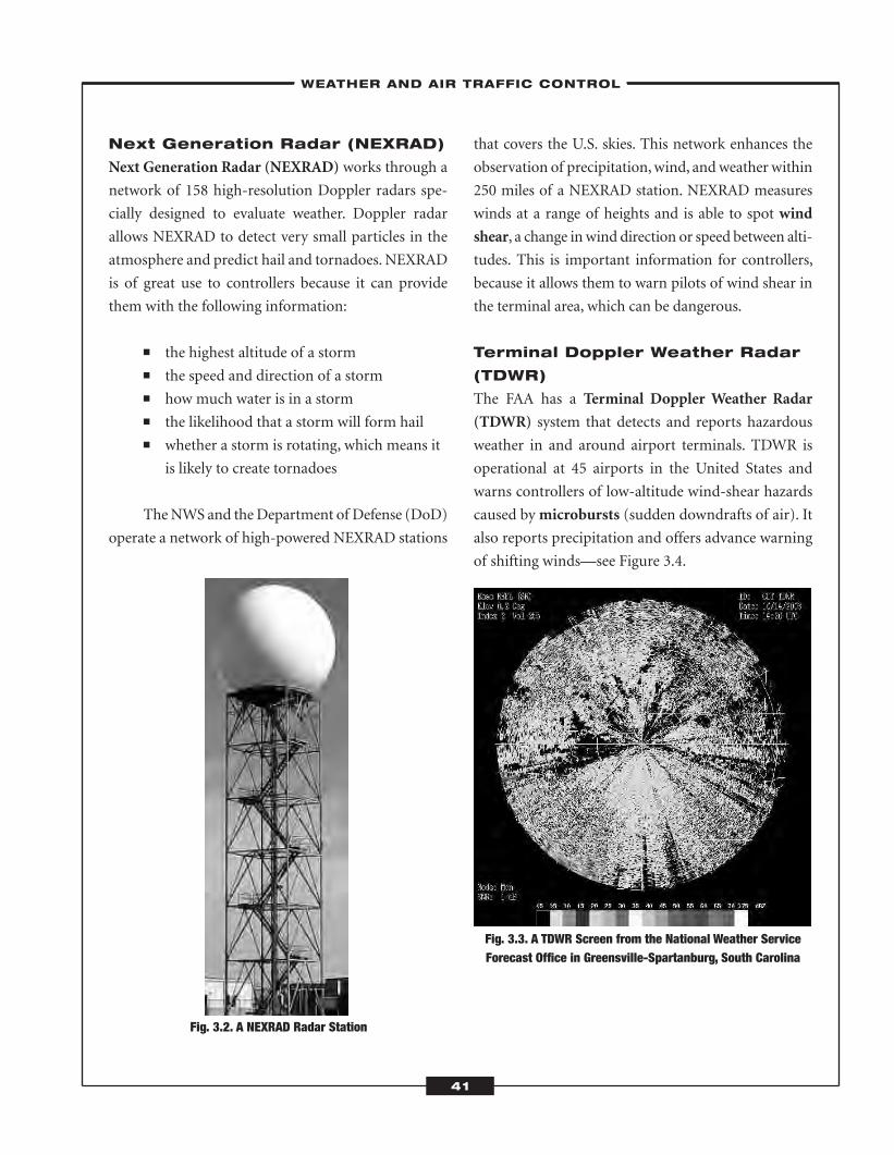
Next Generation Radar (NEXRAD)
Next Generation Radar (NEXRAD) works through a
network of 158 high-resolution Doppler radars spe-
cially designed to evaluate weather. Doppler radar
allows NEXRAD to detect very small particles in the
atmosphere and predict hail and tornadoes.NEXRAD
is of great use to controllers because it can provide
them with the following information:
� the highest altitude of a storm� the speed and direction of a storm� how much water is in a storm� the likelihood that a storm will form hail� whether a storm is rotating, which means it
is likely to create tornadoes
TheNWS and theDepartment of Defense (DoD)
operate a network of high-powered NEXRAD stations
that covers the U.S. skies. This network enhances the
observation of precipitation,wind, andweather within
250 miles of a NEXRAD station. NEXRAD measures
winds at a range of heights and is able to spot wind
shear, a change inwind direction or speed between alti-
tudes. This is important information for controllers,
because it allows them to warn pilots of wind shear in
the terminal area, which can be dangerous.
Terminal Doppler Weather Radar
(TDWR)
The FAA has a Terminal Doppler Weather Radar
(TDWR) system that detects and reports hazardous
weather in and around airport terminals. TDWR is
operational at 45 airports in the United States and
warns controllers of low-altitude wind-shear hazards
caused bymicrobursts (sudden downdrafts of air). It
also reports precipitation and offers advance warning
of shifting winds—see Figure 3.4.
Fig. 3.3. A TDWR Screen from the National Weather ServiceForecast Office in Greensville-Spartanburg, South Carolina
Fig. 3.2. A NEXRAD Radar Station
–WEATHER AND AIR TRAFFIC CONTROL–
41
ATC_2008b:Layout 1 11/24/08 1:14 PM Page 41
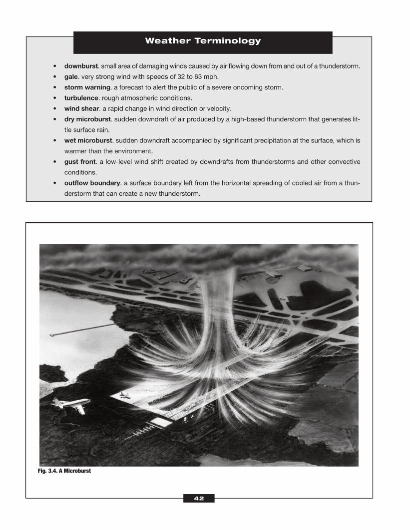
Weather Terminology
• downburst. small area of damaging winds caused by air flowing down from and out of a thunderstorm.
• gale. very strong wind with speeds of 32 to 63 mph.
• storm warning. a forecast to alert the public of a severe oncoming storm.
• turbulence. rough atmospheric conditions.
• wind shear. a rapid change in wind direction or velocity.
• dry microburst. sudden downdraft of air produced by a high-based thunderstorm that generates lit-
tle surface rain.
• wet microburst. sudden downdraft accompanied by significant precipitation at the surface, which is
warmer than the environment.
• gust front. a low-level wind shift created by downdrafts from thunderstorms and other convective
conditions.
• outflow boundary. a surface boundary left from the horizontal spreading of cooled air from a thun-
derstorm that can create a new thunderstorm.
Fig. 3.4. A Microburst
42
ATC_2008b:Layout 1 11/24/08 1:14 PM Page 42
Upper-Air Observations
The atmosphere has layers, which means the weather
on the ground may not be the same as the weather at
a higher altitude. This makes it necessary for meteo-
rologists to make observations of the weather up high,
called upper-air observations. Meteorologists make
these observations in two ways: (1) with a weather bal-
loon, a method referred to as radiosonde observa-
tions; or (2) by listening to pilots’ reports on
conditions from their positions. In both types of
upper-air observations, temperature, pressure, humid-
ity, wind speed, and wind direction are recorded.
Satellite Observations
One of the most accurate sources of weather observa-
tion are weather satellites. These satellites orbit the
earth in either a stationary orbit,which enables them to
observe the same area 24 hours a day, or a low, north-
to-south orbit that takes them over the poles to gather
higher resolution data.TheNWSuses orbiting satellites
belonging to the United States and partner nations.
These global observations come in near-real time.
� Weather Reports andForecasts
Weather forecasts are reports of likely weather condi-
tions based upon analyses of trends and meteorologi-
cal data. In the last section, you learned the different
methods used to make weather observations. You also
learned that controllers use weather reports and fore-
casts to navigate aircraft into and out of terminals. Each
of the weather reports and forecasts controllers use has
its own focus and range, although some may overlap.
The METAR
The Meteorological Aviation Report (METAR) is a
coded format for describing weather conditions at a
specific time and place. The one- or two-line report is
standardized internationally, though individual
nations are allowed to make small adjustments. The
United States, for example, uses miles instead of the
standard kilometers. Controllers, pilots, and meteo-
rologists use the METAR to create forecasts.
The METAR has 12 elements:
1. type of report—The report may be one of
two types: the METAR, which is issued
hourly, or the SPECI, which may be issued
Dangerous Thunderstorms
Weather is a primary factor in more than 35 percent of commercial aviation fatal accidents with thunderstorms
playing a major role. Flashes of lightning can temporarily blind pilots and cause them to lose control of their
aircraft. In a few instances, lighting strikes have caused cabin fires and even fuel-tank explosions. Hail from
thunderstorms can also damage aircraft. Large hail may crack an aircraft’s windshield or damage flaps and sur-
faces. The most dangerous aspect of a thunderstorm, however, is the powerful convective motion of the air:
within a storm cell, powerful updrafts and downdrafts may cause sudden changes in altitude of several thou-
sand feet, which may damage the aircraft. Controllers rate thunderstorms from 1 (weak) to 6 (extreme) and use
NEXRAD, a radar that can identify precipitation, to direct aircraft around thunderstorms.
43
ATC_2008b:Layout 1 11/24/08 1:14 PM Page 43
John Jeffries
On November 30, 1784, John Jeffries, along with balloonist John Pierre Blanchard, ascended to 9,309 feet over
London, England, and became the first scientist to use balloons to study the atmosphere. Jeffries took sam-
ples of the atmosphere’s temperature, pressure, and humidity from various altitudes. That flight brought the
reality of weather balloons to life. Measurements taken by Jeffries continue to hold up to modern scrutiny.
at any time if a change in conditions war-
rants it. Typically, a change fromVFR to IFR
will result in a SPECI issuance.
METAR KLAX 180752Z AUTO 27010KT 1SM
R35L/4500V6000FT –RA BR BKN030 10/80 A2990
RMK A02
2. International Civil Aviation Organization
(ICAO) station identifier—This is the four-
letter code that uses the three-letter terminal
stem preceded by the letter K. For example,
Los Angeles (LAX) has an ICAO of KLAX.
All Canadian ICAOs begin with CY fol-
lowed by a two-letter code identifying the
airport. For example, Toronto, has a ICAO
of CYYZ. Pacific U.S. locations prefix termi-
nal codes with P followed by A, H, or G,
depending on their location. For example,
Anchorage (ANC) becomes PANC and
Honolulu (HNL) becomes PHNL.
METAR KLAX 180752Z AUTO 27010KT 1SM
R35L/4500V6000FT –RA BR BKN030 10/80 A2990
RMK A02
3. date and time of report—The date and
time are reported as six digits: the first two
are the date, the next two are the hour, and
the final two are the minutes. Times are
given in coordinated universal time (UTC),
which is indicated with a Z at the end of the
date/time code. For example, the code
180752Z suggests that the report was issued
on the eighteenth day of the month at
7:52 UTC.
METAR KLAX 180752Z AUTO 27010KT 1SM
R35L/4500V6000FT –RA BR BKN030 10/80 A2990
RMK A02
4. modifier (if necessary)—The modifier dis-
closes whether the report was measured and
issued automatically or if it had human
input either in the observation or the inter-
pretation of the phenomena. If AUTO does
appear, the letters “A01” or “A02”will appear
in the remarks section at the end of the
report as an indication of the type of pre-
cipitation sensor used.
METAR KLAX 180752Z AUTO 27010KT 1SM
R35L/4500V6000FT –RA BR BKN030 10/80 A2990
RMK A02
5. wind speed—Wind speed is reported as a
five- or six-digit code. The first three digits
reflect the compass heading from which the
44
ATC_2008b:Layout 1 11/24/08 1:14 PM Page 44
wind is coming (i.e., 270 degrees), and the
next two or three digits reflect the speed in
knots (i.e., 10 knots) with KT as an abbrevi-
ation for knots. A wind of zero is reported
as 00000KT. If the direction of the wind is
changing rapidly by more than 60 degrees, it
is reported as variable and coded as “VRB”
(i.e., VRB10KT). Gusty winds with sudden
changes of more than 10 knots are coded as
“G” (i.e., 270G10KT). Remarks on wind will
appear in the “remarks” section regarding
peak winds (i.e., PKWND), sudden wind
shifts (i.e.,WSHFT), or the passage of a
front (i.e., FROPA).
METAR KLAX 180752Z AUTO 27010KT 1SM
R35L/4500V6000FT –RA BR BKN030 10/80 A2990
RMK A02
6. visibility—Visibility is noted in statute
miles (SM) in the United States. Other
nations use meters or kilometers. Prevailing
visibility is the greatest visibility throughout
at least half a horizon circle. If prevailing
visibility is less than seven miles, a restric-
tion of visibility is noted on the METAR,
unless this restriction is caused by volcanic
ash, dust, sand, or snow, which will be
reported regardless of visual restriction. In
this example, the visibility is 2 SM:
METAR KLAX 180752Z AUTO 27010KT 2SM
R35L/4500V6000FT –RA BR BKN030 10/80 A2990
RMK A02.
If tower visibility is different from surface
visibility, it will be noted in the remarks.
The lesser distance appears in the visibility
section of the METAR, and the greater dis-
tance appears in the remarks (i.e., TWRVIS
1 would appear in the visibility section
while SFC VIS 2 would appear in the
remarks).
7. runway visual range (RVR)—This is an
automated report of runway visibility in
hundreds of feet. RVR is only reported if
prevailing visibility is less than 1 SM or if
RVR is less than 6,000 feet. This example
shows that runway 35 Left has a varying vis-
ibility from 4,500 to 6,000 feet.
METAR KLAX 180752Z AUTO 27010KT 1SM
R35L/4500V6000FT –RA BR BKN030 10/80 A2990
RMK A02
8. weather phenomena—Weather phenomena
appear in the METAR as a set of “qualifiers”
or descriptors along with the codes for the
phenomena themselves. Some examples of
qualifiers are + or – for heavy and light,
showers (SH), blowing (BL), or freezing
(FZ).While there are numerous actual phe-
nomena, they fall into three groups: precipi-
tation (i.e., DZ for drizzle and RA for rain),
obscuration (i.e., FG for fog and HZ for
haze), and other (i.e., SQ for squalls and FC
for funnel cloud). This example advises of
“light rain and mist.”
METAR KLAX 180752Z AUTO 27010KT 1SM
R35L/4500V6000FT –RA BR BKN030 10/80 A2990
RMK A02
9. sky condition—Sky condition is the per-
centage of cloud cover and cloud height; it
may also describe cloud type. Clouds are
described as clear, few, scattered, broken, or
–WEATHER AND AIR TRAFFIC CONTROL–
45
12
ATC_2008b:Layout 1 11/24/08 1:14 PM Page 45
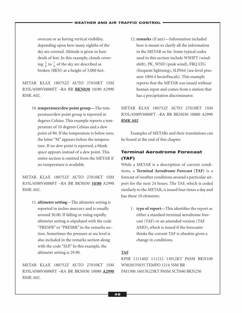
overcast or as having vertical visibility,
depending upon how many eighths of the
sky are covered. Altitude is given in hun-
dreds of feet. In this example, clouds cover-
ing to of the sky are described as
broken (BKN) at a height of 3,000 feet.
METAR KLAX 180752Z AUTO 27010KT 1SM
R35L/4500V6000FT –RA BR BKN030 10/80 A2990
RMK A02.
10. temperature/dew point group—The tem-
perature/dew point group is reported in
degrees Celsius. This example reports a tem-
perature of 10 degrees Celsius and a dew
point of 80. If the temperature is below zero,
the letter “M” appears before the tempera-
ture. If no dew point is reported, a blank
space appears instead of a dew point. This
entire section is omitted from the METAR if
no temperature is available.
METAR KLAX 180752Z AUTO 27010KT 1SM
R35L/4500V6000FT –RA BR BKN030 10/80 A2990
RMK A02.
11. altimeter setting—The altimeter setting is
reported in inches mercury and is usually
around 30.00. If falling or rising rapidly,
altimeter setting is stipulated with the code
“PRESFR” or “PRESRR” in the remarks sec-
tion. Sometimes the pressure at sea level is
also included in the remarks section along
with the code “SLP.” In this example, the
altimeter setting is 29.90.
METAR KLAX 180752Z AUTO 27010KT 1SM
R35L/4500V6000FT –RA BR BKN030 10080 A2990
RMK A02.
12. remarks (if any)—Information included
here is meant to clarify all the information
in the METAR so far. Some typical codes
used in this section includeWSHFT (wind-
shift), PK_WND (peak wind), FRQ LTG
(frequent lightning), SLP044 (sea-level pres-
sure 1004.4 hectoPascals). This example
reports that the METAR was issued without
human input and comes from a station that
has a precipitation discriminator.
METAR KLAX 180752Z AUTO 27010KT 1SM
R35L/4500V6000FT –RA BR BKN030 10080 A2990
RMKA02
Examples of METARs and their translations can
be found at the end of this chapter.
Terminal Aerodrome Forecast
(TAF)
While a METAR is a description of current condi-
tions, a Terminal Aerodrome Forecast (TAF) is a
forecast of weather conditions around a particular air-
port for the next 24 hours. The TAF, which is coded
similarly to theMETAR, is issued four times a day and
has these 10 elements:
1. type of report—This identifies the report as
either a standard terminal aerodrome fore-
cast (TAF) or an amended version (TAF
AMD), which is issued if the forecaster
thinks the current TAF is obsolete given a
change in conditions.
TAF
KPIR 111140Z 111212 13012KT P6SM BKN100
WS020/35035 TEMPO 1214 5SM BR
FM1500 16015G25KT P6SM SCT040 BKN250
–WEATHER AND AIR TRAFFIC CONTROL–
46
58
78
ATC_2008b:Layout 1 11/24/08 1:14 PM Page 46
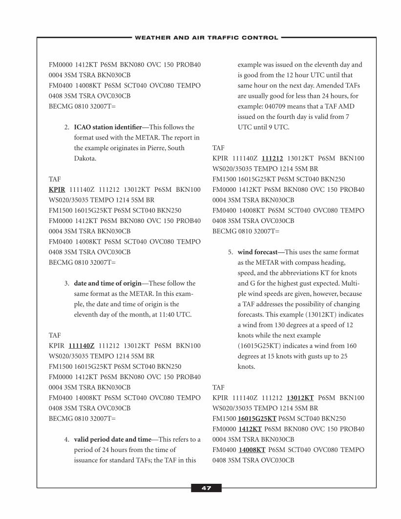
FM0000 1412KT P6SM BKN080 OVC 150 PROB40
0004 3SM TSRA BKN030CB
FM0400 14008KT P6SM SCT040 OVC080 TEMPO
0408 3SM TSRA OVC030CB
BECMG 0810 32007T=
2. ICAO station identifier—This follows the
format used with the METAR. The report in
the example originates in Pierre, South
Dakota.
TAF
KPIR 111140Z 111212 13012KT P6SM BKN100
WS020/35035 TEMPO 1214 5SM BR
FM1500 16015G25KT P6SM SCT040 BKN250
FM0000 1412KT P6SM BKN080 OVC 150 PROB40
0004 3SM TSRA BKN030CB
FM0400 14008KT P6SM SCT040 OVC080 TEMPO
0408 3SM TSRA OVC030CB
BECMG 0810 32007T=
3. date and time of origin—These follow the
same format as the METAR. In this exam-
ple, the date and time of origin is the
eleventh day of the month, at 11:40 UTC.
TAF
KPIR 111140Z 111212 13012KT P6SM BKN100
WS020/35035 TEMPO 1214 5SM BR
FM1500 16015G25KT P6SM SCT040 BKN250
FM0000 1412KT P6SM BKN080 OVC 150 PROB40
0004 3SM TSRA BKN030CB
FM0400 14008KT P6SM SCT040 OVC080 TEMPO
0408 3SM TSRA OVC030CB
BECMG 0810 32007T=
4. valid period date and time—This refers to a
period of 24 hours from the time of
issuance for standard TAFs; the TAF in this
example was issued on the eleventh day and
is good from the 12 hour UTC until that
same hour on the next day. Amended TAFs
are usually good for less than 24 hours, for
example: 040709 means that a TAF AMD
issued on the fourth day is valid from 7
UTC until 9 UTC.
TAF
KPIR 111140Z 111212 13012KT P6SM BKN100
WS020/35035 TEMPO 1214 5SM BR
FM1500 16015G25KT P6SM SCT040 BKN250
FM0000 1412KT P6SM BKN080 OVC 150 PROB40
0004 3SM TSRA BKN030CB
FM0400 14008KT P6SM SCT040 OVC080 TEMPO
0408 3SM TSRA OVC030CB
BECMG 0810 32007T=
5. wind forecast—This uses the same format
as the METAR with compass heading,
speed, and the abbreviations KT for knots
and G for the highest gust expected. Multi-
ple wind speeds are given, however, because
a TAF addresses the possibility of changing
forecasts. This example (13012KT) indicates
a wind from 130 degrees at a speed of 12
knots while the next example
(16015G25KT) indicates a wind from 160
degrees at 15 knots with gusts up to 25
knots.
TAF
KPIR 111140Z 111212 13012KT P6SM BKN100
WS020/35035 TEMPO 1214 5SM BR
FM1500 16015G25KT P6SM SCT040 BKN250
FM0000 1412KT P6SM BKN080 OVC 150 PROB40
0004 3SM TSRA BKN030CB
FM0400 14008KT P6SM SCT040 OVC080 TEMPO
0408 3SM TSRA OVC030CB
–WEATHER AND AIR TRAFFIC CONTROL–
47
ATC_2008b:Layout 1 11/24/08 1:14 PM Page 47
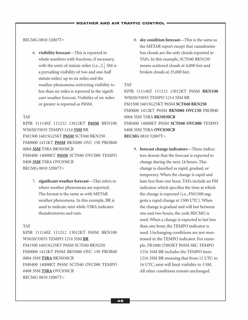
BECMG 0810 32007T=
6. visibility forecast—This is reported in
whole numbers with fractions, if necessary,
with the units of statute miles (i.e., 2 SM is
a prevailing visibility of two and one-half
statute miles) up to six miles and the
weather phenomena restricting visibility to
less than six miles is reported in the signifi-
cant weather forecast. Visibility of six miles
or greater is reported as P6SM.
TAF
KPIR 111140Z 111212 13012KT P6SM BKN100
WS020/35035 TEMPO 1214 5SM BR
FM1500 16015G25KT P6SM SCT040 BKN250
FM0000 1412KT P6SM BKN080 OVC 150 PROB40
0004 3SM TSRA BKN030CB
FM0400 14008KT P6SM SCT040 OVC080 TEMPO
0408 3SM TSRA OVC030CB
BECMG 0810 32007T=
7. significant weather forecast—This refers to
where weather phenomena are reported.
The format is the same as with METAR
weather phenomena. In this example, BR is
used to indicate mist while TSRA indicates
thunderstorms and rain.
TAF
KPIR 111140Z 111212 13012KT P6SM BKN100
WS020/35035 TEMPO 1214 5SM BR
FM1500 16015G25KT P6SM SCT040 BKN250
FM0000 1412KT P6SM BKN080 OVC 150 PROB40
0004 3SM TSRA BKN030CB
FM0400 14008KT P6SM SCT040 OVC080 TEMPO
0408 3SM TSRA OVC030CB
BECMG 0810 32007T=
8. sky condition forecast—This is the same as
the METAR report except that cumulonim-
bus clouds are the only clouds reported in
TAFs. In this example, SCT040 BKN250
means scattered clouds at 4,000 feet and
broken clouds at 25,000 feet.
TAF
KPIR 111140Z 111212 13012KT P6SM BKN100
WS020/35035 TEMPO 1214 5SM BR
FM1500 16015G25KT P6SM SCT040 BKN250
FM0000 1412KT P6SM BKN080 OVC150 PROB40
0004 3SM TSRA BKN030CB
FM0400 14008KT P6SM SCT040 OVC080 TEMPO
0408 3SM TSRA OVC030CB
BECMG 0810 32007T=
9. forecast change indicators—These indica-
tors denote that the forecast is expected to
change during the next 24 hours. This
change is classified as rapid, gradual, or
temporary.When the change is rapid and
lasts less than one hour, TAFs include an FM
indicator, which specifies the time at which
the change is expected (i.e., FM1500 sug-
gests a rapid change at 1500 UTC).When
the change is gradual and will last between
one and two hours, the code BECMG is
used.When a change is expected to last less
than one hour, the TEMPO indicator is
used. Unchanging conditions are not men-
tioned in the TEMPO indicator. For exam-
ple, FR1000 27005KT P6SM SKC TEMPO
1216 3SM BR includes the TEMPO item:
1216 3SM BR meaning that from 12 UTC to
16 UTC, mist will limit visibility to 3 SM.
All other conditions remain unchanged.
–WEATHER AND AIR TRAFFIC CONTROL–
48
12
ATC_2008b:Layout 1 11/24/08 1:14 PM Page 48
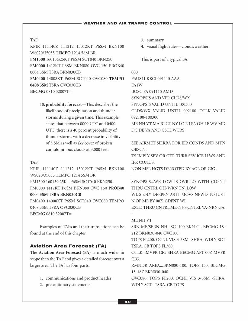
TAF
KPIR 111140Z 111212 13012KT P6SM BKN100
WS020/35035 TEMPO 1214 5SM BR
FM1500 16015G25KT P6SM SCT040 BKN250
FM0000 1412KT P6SM BKN080 OVC 150 PROB40
0004 3SM TSRA BKN030CB
FM0400 14008KT P6SM SCT040 OVC080 TEMPO
0408 3SM TSRA OVC030CB
BECMG 0810 32007T=
10. probability forecast—This describes the
likelihood of precipitation and thunder-
storms during a given time. This example
states that between 0000 UTC and 0400
UTC, there is a 40 percent probability of
thunderstorms with a decrease in visibility
of 3 SM as well as sky cover of broken
cumulonimbus clouds at 3,000 feet.
TAF
KPIR 111140Z 111212 13012KT P6SM BKN100
WS020/35035 TEMPO 1214 5SM BR
FM1500 16015G25KT P6SM SCT040 BKN250
FM0000 1412KT P6SM BKN080 OVC 150 PROB40
0004 3SM TSRA BKN030CB
FM0400 14008KT P6SM SCT040 OVC080 TEMPO
0408 3SM TSRA OVC030CB
BECMG 0810 32007T=
Examples of TAFs and their translations can be
found at the end of this chapter.
Aviation Area Forecast (FA)
The Aviation Area Forecast (FA) is much wider in
scope than the TAF and gives a detailed forecast over a
larger area. The FA has four parts:
1. communications and product header
2. precautionary statements
3. summary
4. visual flight rules—clouds/weather
This is part of a typical FA:
000
FAUS41 KKCI 091115 AAA
FA1W
BOSC FA 091115 AMD
SYNOPSIS ANDVFR CLDS/WX
SYNOPSIS VALID UNTIL 100300
CLDS/WX VALID UNTIL 092100...OTLK VALID
092100-100300
ME NHVTMA RI CT NY LONJ PA OH LEWVMD
DC DEVA AND CSTLWTRS
.
SEE AIRMET SIERRA FOR IFR CONDS AND MTN
OBSCN.
TS IMPLY SEV OR GTR TURB SEV ICE LLWS AND
IFR CONDS.
NONMSL HGTS DENOTED BY AGL OR CIG.
.
SYNOPSIS...WK LOW IS OVR LO WITH CDFNT
THRU CNTRL OH-WRN TN. LOW
WL SLOLY DEEPEN AS IT MOVS NEWD TO JUST
N OF ME BY 00Z. CDFNTWL
EXTDTHRUCNTRLME-NJ-S CNTRLVA-NRNGA.
.
ME NHVT
SRN ME/SERN NH...SCT100 BKN CI. BECMG 18-
21Z BKN030-040 OVC100.
TOPS FL200. OCNL VIS 3-5SM -SHRA. WDLY SCT
TSRA. CB TOPS FL380.
OTLK...MVFR CIG SHRA BECMG AFT 00Z MVFR
CIG.
RMNDR AREA...BKN080-100. TOPS 150. BECMG
15-18Z BKN030-040
OVC080. TOPS FL200. OCNL VIS 3-5SM -SHRA.
WDLY SCT -TSRA. CB TOPS
–WEATHER AND AIR TRAFFIC CONTROL–
49
ATC_2008b:Layout 1 11/24/08 1:14 PM Page 49
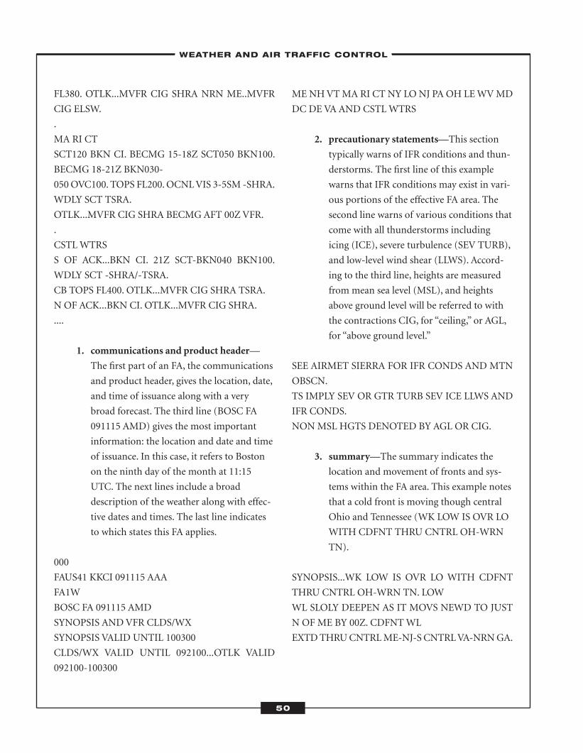
FL380. OTLK...MVFR CIG SHRA NRN ME..MVFR
CIG ELSW.
.
MA RI CT
SCT120 BKN CI. BECMG 15-18Z SCT050 BKN100.
BECMG 18-21Z BKN030-
050OVC100. TOPS FL200.OCNLVIS 3-5SM -SHRA.
WDLY SCT TSRA.
OTLK...MVFR CIG SHRA BECMG AFT 00Z VFR.
.
CSTLWTRS
S OF ACK...BKN CI. 21Z SCT-BKN040 BKN100.
WDLY SCT -SHRA/-TSRA.
CB TOPS FL400. OTLK...MVFR CIG SHRA TSRA.
N OF ACK...BKN CI. OTLK...MVFR CIG SHRA.
....
1. communications and product header—
The first part of an FA, the communications
and product header, gives the location, date,
and time of issuance along with a very
broad forecast. The third line (BOSC FA
091115 AMD) gives the most important
information: the location and date and time
of issuance. In this case, it refers to Boston
on the ninth day of the month at 11:15
UTC. The next lines include a broad
description of the weather along with effec-
tive dates and times. The last line indicates
to which states this FA applies.
000
FAUS41 KKCI 091115 AAA
FA1W
BOSC FA 091115 AMD
SYNOPSIS ANDVFR CLDS/WX
SYNOPSIS VALID UNTIL 100300
CLDS/WX VALID UNTIL 092100...OTLK VALID
092100-100300
ME NHVTMA RI CT NY LONJ PA OH LEWVMD
DC DEVA AND CSTLWTRS
2. precautionary statements—This section
typically warns of IFR conditions and thun-
derstorms. The first line of this example
warns that IFR conditions may exist in vari-
ous portions of the effective FA area. The
second line warns of various conditions that
come with all thunderstorms including
icing (ICE), severe turbulence (SEV TURB),
and low-level wind shear (LLWS). Accord-
ing to the third line, heights are measured
from mean sea level (MSL), and heights
above ground level will be referred to with
the contractions CIG, for “ceiling,” or AGL,
for “above ground level.”
SEE AIRMET SIERRA FOR IFR CONDS AND MTN
OBSCN.
TS IMPLY SEV OR GTR TURB SEV ICE LLWS AND
IFR CONDS.
NONMSL HGTS DENOTED BY AGL OR CIG.
3. summary—The summary indicates the
location and movement of fronts and sys-
tems within the FA area. This example notes
that a cold front is moving though central
Ohio and Tennessee (WK LOW IS OVR LO
WITH CDFNT THRU CNTRL OH-WRN
TN).
SYNOPSIS...WK LOW IS OVR LO WITH CDFNT
THRU CNTRL OH-WRN TN. LOW
WL SLOLY DEEPEN AS IT MOVS NEWD TO JUST
N OF ME BY 00Z. CDFNTWL
EXTDTHRUCNTRLME-NJ-S CNTRLVA-NRNGA.
–WEATHER AND AIR TRAFFIC CONTROL–
50
ATC_2008b:Layout 1 11/24/08 1:14 PM Page 50
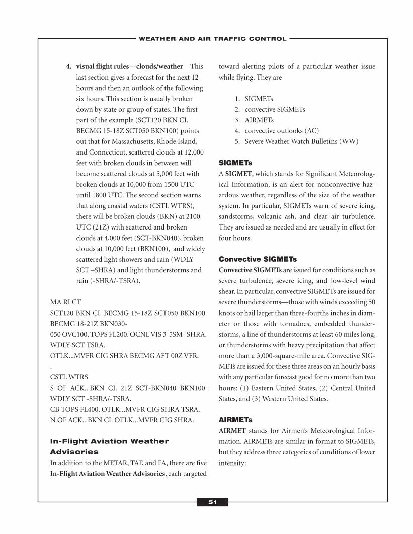
4. visual flight rules—clouds/weather—This
last section gives a forecast for the next 12
hours and then an outlook of the following
six hours. This section is usually broken
down by state or group of states. The first
part of the example (SCT120 BKN CI.
BECMG 15-18Z SCT050 BKN100) points
out that for Massachusetts, Rhode Island,
and Connecticut, scattered clouds at 12,000
feet with broken clouds in between will
become scattered clouds at 5,000 feet with
broken clouds at 10,000 from 1500 UTC
until 1800 UTC. The second section warns
that along coastal waters (CSTLWTRS),
there will be broken clouds (BKN) at 2100
UTC (21Z) with scattered and broken
clouds at 4,000 feet (SCT-BKN040), broken
clouds at 10,000 feet (BKN100), and widely
scattered light showers and rain (WDLY
SCT –SHRA) and light thunderstorms and
rain (-SHRA/-TSRA).
MA RI CT
SCT120 BKN CI. BECMG 15-18Z SCT050 BKN100.
BECMG 18-21Z BKN030-
050OVC100. TOPS FL200.OCNLVIS 3-5SM -SHRA.
WDLY SCT TSRA.
OTLK...MVFR CIG SHRA BECMG AFT 00Z VFR.
.
CSTLWTRS
S OF ACK...BKN CI. 21Z SCT-BKN040 BKN100.
WDLY SCT -SHRA/-TSRA.
CB TOPS FL400. OTLK...MVFR CIG SHRA TSRA.
N OF ACK...BKN CI. OTLK...MVFR CIG SHRA.
In-Flight Aviation Weather
Advisories
In addition to the METAR, TAF, and FA, there are five
In-Flight AviationWeatherAdvisories, each targeted
toward alerting pilots of a particular weather issue
while flying. They are
1. SIGMETs
2. convective SIGMETs
3. AIRMETs
4. convective outlooks (AC)
5. Severe Weather Watch Bulletins (WW)
SIGMETsA SIGMET, which stands for Significant Meteorolog-
ical Information, is an alert for nonconvective haz-
ardous weather, regardless of the size of the weather
system. In particular, SIGMETs warn of severe icing,
sandstorms, volcanic ash, and clear air turbulence.
They are issued as needed and are usually in effect for
four hours.
Convective SIGMETsConvective SIGMETs are issued for conditions such as
severe turbulence, severe icing, and low-level wind
shear. In particular, convective SIGMETs are issued for
severe thunderstorms—those with winds exceeding 50
knots or hail larger than three-fourths inches in diam-
eter or those with tornadoes, embedded thunder-
storms, a line of thunderstorms at least 60 miles long,
or thunderstorms with heavy precipitation that affect
more than a 3,000-square-mile area. Convective SIG-
METs are issued for these three areas on an hourly basis
with any particular forecast good for nomore than two
hours: (1) Eastern United States, (2) Central United
States, and (3) Western United States.
AIRMETsAIRMET stands for Airmen’s Meteorological Infor-
mation. AIRMETs are similar in format to SIGMETs,
but they address three categories of conditions of lower
intensity:
–WEATHER AND AIR TRAFFIC CONTROL–
51
ATC_2008b:Layout 1 11/24/08 1:14 PM Page 51
1. sierra category
2. tango category
3. zulu category
The sierra category describes IFR conditions and
mountain obscurations. The tango category includes
moderate turbulence, surface winds of 30+ knots, and
wind shear (non-convective). The zulu categorywarns
of moderate icing and freezing-level height informa-
tion. AIRMETs are issued every six hours and as
needed.
Convective OutlooksConvective outlooks (AC) are issued by Storm Pre-
diction Center (SPC) and aremeant to be used as flight
planning tools. They are a national forecast of thun-
derstorms and convective weather hazardsmade of two
forecasts: one of the first 24 hours and one of the sec-
ond 24 hours. Each forecast describes areas of slight,
moderate, and severe thunderstorms. Severe thunder-
storms are those with winds of 50 knots or more, hail
of three-fourths inches, or tornadoes.
Severe Weather Watch Bulletins (WW)SevereWeatherWatchBulletins (WW), also issued by
SPC, identify areas of severe thunderstorms or torna-
does. They are issued as needed and include tornado
watches (any area where conditions make a tornado a
possibility). Each bulletin has these parts: the type of
weather to watch for, the area, and the time; other
information linking it to previous watches; particular
phenomenon such as hail size, wind speed, cell direc-
tion, and speed; and the likely cause.
52
–WEATHER AND AIR TRAFFIC CONTROL–
ATC_2008b:Layout 1 11/24/08 1:14 PM Page 52
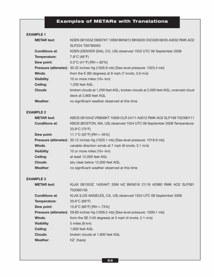
53
Examples of METARs with Translations
EXAMPLE 1
METAR text: KDEN 081553Z 09007KT 10SMBKN012 BKN020 OVC028 08/05 A3032 RMK AO2
SLP234 T00780050
Conditions at: KDEN (DENVER (DIA), CO, US) observed 1553 UTC 08 September 2008
Temperature: 7.8°C (46°F)
Dew point: 5.0°C (41°F) [RH = 82%]
Pressure (altimeter): 30.32 inches Hg (1026.8 mb) [Sea-level pressure: 1023.4 mb]
Winds: from the E (90 degrees) at 8 mph (7 knots; 3.6 m/s)
Visibility: 10 or more miles (16+ km)
Ceiling: 1,200 feet AGL
Clouds: broken clouds at 1,200 feet AGL; broken clouds at 2,000 feet AGL; overcast cloud
deck at 2,800 feet AGL
Weather: no significant weather observed at this time
EXAMPLE 2
METAR text: KBOS 081554Z VRB06KT 10SM CLR 24/11 A3012 RMK AO2 SLP199 T02390111
Conditions at: KBOS (BOSTON, MA, US) observed 1554 UTC 08 September 2008 Temperature:
23.9°C (75°F)
Dew point: 11.1°C (52°F) [RH = 45%]
Pressure (altimeter): 30.12 inches Hg (1020.1 mb) [Sea-level pressure: 1019.9 mb]
Winds: variable direction winds at 7 mph (6 knots; 3.1 m/s)
Visibility: 10 or more miles (16+ km)
Ceiling: at least 12,000 feet AGL
Clouds: sky clear below 12,000 feet AGL
Weather: no significant weather observed at this time
EXAMPLE 3
METAR text: KLAX 081553Z 14004KT 5SM HZ BKN016 21/16 A2980 RMK AO2 SLP091
T02060156
Conditions at: KLAX (LOS ANGELES, CA, US) observed 1553 UTC 08 September 2008
Temperature: 20.6°C (69°F)
Dew point: 15.6°C (60°F) [RH = 73%]
Pressure (altimeter): 29.80 inches Hg (1009.2 mb) [Sea-level pressure: 1009.1 mb]
Winds: from the SE (140 degrees) at 5 mph (4 knots; 2.1 m/s)
Visibility: 5 miles (8 km)
Ceiling: 1,600 feet AGL
Clouds: broken clouds at 1,600 feet AGL
Weather: HZ (haze)
ATC_2008b:Layout 1 11/24/08 1:14 PM Page 53
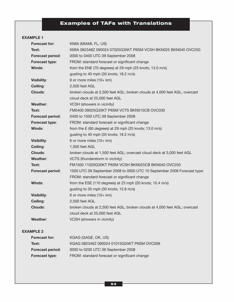
Examples of TAFs with Translations
EXAMPLE 1
Forecast for: KMIA (MIAMI, FL, US)
Text: KMIA 082348Z 090024 07025G35KT P6SM VCSH BKN025 BKN040 OVC250
Forecast period: 0000 to 0400 UTC 09 September 2008
Forecast type: FROM: standard forecast or significant change
Winds: from the ENE (70 degrees) at 29 mph (25 knots; 13.0 m/s)
gusting to 40 mph (35 knots; 18.2 m/s)
Visibility: 6 or more miles (10+ km)
Ceiling: 2,500 feet AGL
Clouds: broken clouds at 2,500 feet AGL; broken clouds at 4,000 feet AGL; overcast
cloud deck at 25,000 feet AGL
Weather: VCSH (showers in vicinity)
Text: FM0400 09025G35KT P6SM VCTS BKN015CB OVC030
Forecast period: 0400 to 1500 UTC 09 September 2008
Forecast type: FROM: standard forecast or significant change
Winds: from the E (90 degrees) at 29 mph (25 knots; 13.0 m/s)
gusting to 40 mph (35 knots; 18.2 m/s)
Visibility: 6 or more miles (10+ km)
Ceiling: 1,500 feet AGL
Clouds: broken clouds at 1,500 feet AGL; overcast cloud deck at 3,000 feet AGL
Weather: VCTS (thunderstorm in vicinity)
Text: FM1500 11020G30KT P6SM VCSH BKN025CB BKN040 OVC250
Forecast period: 1500 UTC 09 September 2008 to 0000 UTC 10 September 2008 Forecast type:
FROM: standard forecast or significant change
Winds: from the ESE (110 degrees) at 23 mph (20 knots; 10.4 m/s)
gusting to 35 mph (30 knots; 15.6 m/s)
Visibility: 6 or more miles (10+ km)
Ceiling: 2,500 feet AGL
Clouds: broken clouds at 2,500 feet AGL; broken clouds at 4,000 feet AGL; overcast
cloud deck at 25,000 feet AGL
Weather: VCSH (showers in vicinity)
EXAMPLE 2
Forecast for: KGAG (GAGE, OK, US)
Text: KGAG 082346Z 090024 01015G20KT P6SM OVC009
Forecast period: 0000 to 0200 UTC 09 September 2008
Forecast type: FROM: standard forecast or significant change
54
ATC_2008b:Layout 1 11/24/08 1:14 PM Page 54
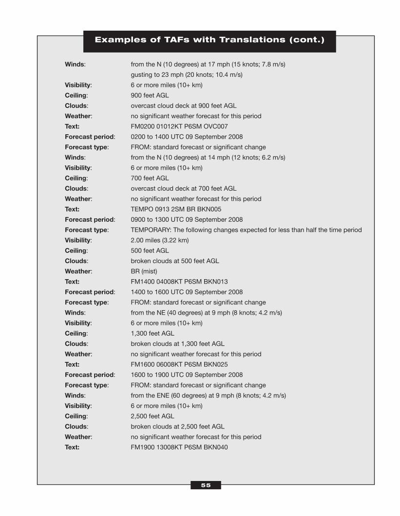
Examples of TAFs with Translations (cont.)
Winds: from the N (10 degrees) at 17 mph (15 knots; 7.8 m/s)
gusting to 23 mph (20 knots; 10.4 m/s)
Visibility: 6 or more miles (10+ km)
Ceiling: 900 feet AGL
Clouds: overcast cloud deck at 900 feet AGL
Weather: no significant weather forecast for this period
Text: FM0200 01012KT P6SM OVC007
Forecast period: 0200 to 1400 UTC 09 September 2008
Forecast type: FROM: standard forecast or significant change
Winds: from the N (10 degrees) at 14 mph (12 knots; 6.2 m/s)
Visibility: 6 or more miles (10+ km)
Ceiling: 700 feet AGL
Clouds: overcast cloud deck at 700 feet AGL
Weather: no significant weather forecast for this period
Text: TEMPO 0913 2SM BR BKN005
Forecast period: 0900 to 1300 UTC 09 September 2008
Forecast type: TEMPORARY: The following changes expected for less than half the time period
Visibility: 2.00 miles (3.22 km)
Ceiling: 500 feet AGL
Clouds: broken clouds at 500 feet AGL
Weather: BR (mist)
Text: FM1400 04008KT P6SM BKN013
Forecast period: 1400 to 1600 UTC 09 September 2008
Forecast type: FROM: standard forecast or significant change
Winds: from the NE (40 degrees) at 9 mph (8 knots; 4.2 m/s)
Visibility: 6 or more miles (10+ km)
Ceiling: 1,300 feet AGL
Clouds: broken clouds at 1,300 feet AGL
Weather: no significant weather forecast for this period
Text: FM1600 06008KT P6SM BKN025
Forecast period: 1600 to 1900 UTC 09 September 2008
Forecast type: FROM: standard forecast or significant change
Winds: from the ENE (60 degrees) at 9 mph (8 knots; 4.2 m/s)
Visibility: 6 or more miles (10+ km)
Ceiling: 2,500 feet AGL
Clouds: broken clouds at 2,500 feet AGL
Weather: no significant weather forecast for this period
Text: FM1900 13008KT P6SM BKN040
55
ATC_2008b:Layout 1 11/24/08 1:14 PM Page 55

56
Examples of TAFs with Translations (cont.)
Forecast period: 1900 UTC 09 September 2008 to 0000 UTC 10 September 2008 Forecast type:
FROM: standard forecast or significant change
Winds: from the SE (130 degrees) at 9 mph (8 knots; 4.2 m/s)
Visibility: 6 or more miles (10+ km)
Ceiling: 4,000 feet AGL
Clouds: broken clouds at 4,000 feet AGL
Weather: no significant weather forecast for this period
ATC_2008b:Layout 1 11/24/08 1:14 PM Page 56
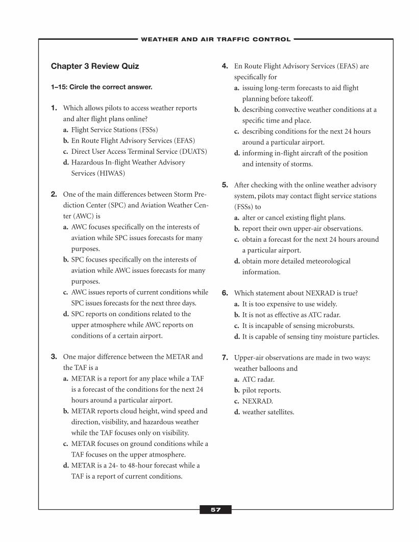
Chapter 3 Review Quiz
1–15: Circle the correct answer.
1. Which allows pilots to access weather reportsand alter flight plans online?
a. Flight Service Stations (FSSs)
b. En Route Flight Advisory Services (EFAS)
c. Direct User Access Terminal Service (DUATS)
d. Hazardous In-flight Weather Advisory
Services (HIWAS)
2. One of the main differences between Storm Pre-diction Center (SPC) and AviationWeather Cen-
ter (AWC) is
a. AWC focuses specifically on the interests of
aviation while SPC issues forecasts for many
purposes.
b. SPC focuses specifically on the interests of
aviation while AWC issues forecasts for many
purposes.
c. AWC issues reports of current conditions while
SPC issues forecasts for the next three days.
d. SPC reports on conditions related to the
upper atmosphere while AWC reports on
conditions of a certain airport.
3. One major difference between the METAR andthe TAF is a
a. METAR is a report for any place while a TAF
is a forecast of the conditions for the next 24
hours around a particular airport.
b. METAR reports cloud height, wind speed and
direction, visibility, and hazardous weather
while the TAF focuses only on visibility.
c. METAR focuses on ground conditions while a
TAF focuses on the upper atmosphere.
d. METAR is a 24- to 48-hour forecast while a
TAF is a report of current conditions.
4. En Route Flight Advisory Services (EFAS) arespecifically for
a. issuing long-term forecasts to aid flight
planning before takeoff.
b. describing convective weather conditions at a
specific time and place.
c. describing conditions for the next 24 hours
around a particular airport.
d. informing in-flight aircraft of the position
and intensity of storms.
5. After checking with the online weather advisorysystem, pilots may contact flight service stations
(FSSs) to
a. alter or cancel existing flight plans.
b. report their own upper-air observations.
c. obtain a forecast for the next 24 hours around
a particular airport.
d. obtain more detailed meteorological
information.
6. Which statement about NEXRAD is true?a. It is too expensive to use widely.
b. It is not as effective as ATC radar.
c. It is incapable of sensing microbursts.
d. It is capable of sensing tiny moisture particles.
7. Upper-air observations are made in two ways:weather balloons and
a. ATC radar.
b. pilot reports.
c. NEXRAD.
d. weather satellites.
–WEATHER AND AIR TRAFFIC CONTROL–
57
ATC_2008b:Layout 1 11/24/08 1:14 PM Page 57
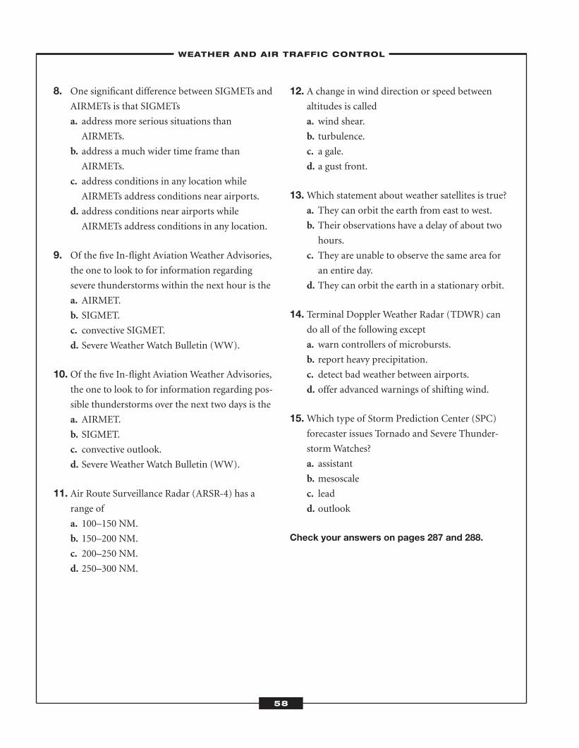
8. One significant difference between SIGMETs andAIRMETs is that SIGMETs
a. address more serious situations than
AIRMETs.
b. address a much wider time frame than
AIRMETs.
c. address conditions in any location while
AIRMETs address conditions near airports.
d. address conditions near airports while
AIRMETs address conditions in any location.
9. Of the five In-flight AviationWeather Advisories,the one to look to for information regarding
severe thunderstorms within the next hour is the
a. AIRMET.
b. SIGMET.
c. convective SIGMET.
d. Severe Weather Watch Bulletin (WW).
10. Of the five In-flight AviationWeather Advisories,the one to look to for information regarding pos-
sible thunderstorms over the next two days is the
a. AIRMET.
b. SIGMET.
c. convective outlook.
d. Severe Weather Watch Bulletin (WW).
11. Air Route Surveillance Radar (ARSR-4) has arange of
a. 100–150 NM.
b. 150–200 NM.
c. 200–250 NM.
d. 250–300 NM.
12. A change in wind direction or speed betweenaltitudes is called
a. wind shear.
b. turbulence.
c. a gale.
d. a gust front.
13.Which statement about weather satellites is true?a. They can orbit the earth from east to west.
b. Their observations have a delay of about two
hours.
c. They are unable to observe the same area for
an entire day.
d. They can orbit the earth in a stationary orbit.
14. Terminal Doppler Weather Radar (TDWR) cando all of the following except
a. warn controllers of microbursts.
b. report heavy precipitation.
c. detect bad weather between airports.
d. offer advanced warnings of shifting wind.
15.Which type of Storm Prediction Center (SPC)forecaster issues Tornado and Severe Thunder-
stormWatches?
a. assistant
b. mesoscale
c. lead
d. outlook
Check your answers on pages 287 and 288.
–WEATHER AND AIR TRAFFIC CONTROL–
58
ATC_2008b:Layout 1 11/24/08 1:14 PM Page 58
C H A P T E R
59
The Federal Aviation Administration (FAA) publishes aeronautical charts for both visual flight rules
(VFR) and instrument flight rules (IFR) aircraft. Aeronautical charts illustrate topography, such as
landmarks, and the location of navigational aids for controllers and pilots.
Pilots and controllers must take care to use the most current charts for navigation—using obsolete charts
is dangerous. Navigation information often changes, and pilots and controllers should check the effective dates
on a chart before using it. The next scheduled edition date of the chart appears on its cover. You can also consult
Aeronautical Chart Bulletins in the Airport/Facility Directory (A/FD) or the National Aeronautical Charting
Office (NACO) Web site (http://naco.faa.gov). Pay close attention to NOTAMs (notices to airmen) for changes
affecting flight that occur during a chart’s effective dates.
Charting andAir TrafficControl
CHAPTER SUMMARYAeronautical charts are available for both VFR and IFR flights. Con-
trollers use these charts for navigation. Sectional charts are the most
common charts used to navigate VFR flights. Controllers guiding pilots
flying IFR aircraft frequently reference several charts, including en route
low- and high-altitude charts.
4
ATC_2008b:Layout 1 11/24/08 1:14 PM Page 59
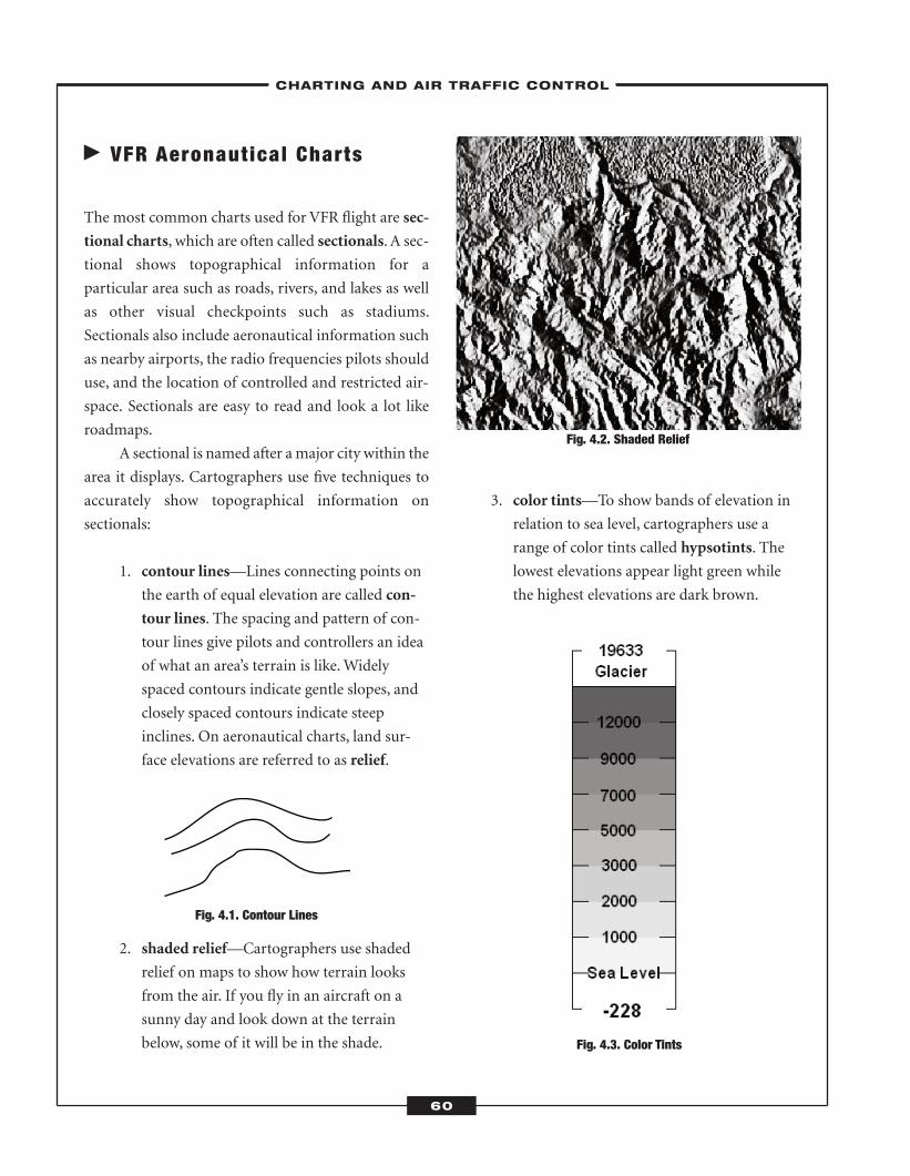
� VFR Aeronautical Charts
The most common charts used for VFR flight are sec-
tional charts, which are often called sectionals. A sec-
tional shows topographical information for a
particular area such as roads, rivers, and lakes as well
as other visual checkpoints such as stadiums.
Sectionals also include aeronautical information such
as nearby airports, the radio frequencies pilots should
use, and the location of controlled and restricted air-
space. Sectionals are easy to read and look a lot like
roadmaps.
A sectional is named after amajor city within the
area it displays. Cartographers use five techniques to
accurately show topographical information on
sectionals:
1. contour lines—Lines connecting points on
the earth of equal elevation are called con-
tour lines. The spacing and pattern of con-
tour lines give pilots and controllers an idea
of what an area’s terrain is like.Widely
spaced contours indicate gentle slopes, and
closely spaced contours indicate steep
inclines. On aeronautical charts, land sur-
face elevations are referred to as relief.
Fig. 4.1. Contour Lines
2. shaded relief—Cartographers use shaded
relief on maps to show how terrain looks
from the air. If you fly in an aircraft on a
sunny day and look down at the terrain
below, some of it will be in the shade.
3. color tints—To show bands of elevation in
relation to sea level, cartographers use a
range of color tints called hypsotints. The
lowest elevations appear light green while
the highest elevations are dark brown.
Fig. 4.3. Color Tints
Fig. 4.2. Shaded Relief
–CHARTING AND AIR TRAFFIC CONTROL–
60
ATC_2008b:Layout 1 11/24/08 1:14 PM Page 60
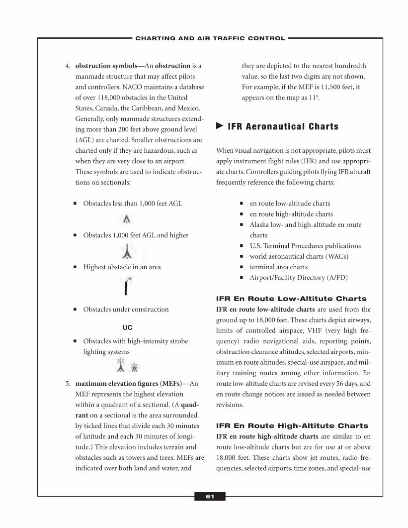
4. obstruction symbols—An obstruction is a
manmade structure that may affect pilots
and controllers. NACO maintains a database
of over 118,000 obstacles in the United
States, Canada, the Caribbean, and Mexico.
Generally, only manmade structures extend-
ing more than 200 feet above ground level
(AGL) are charted. Smaller obstructions are
charted only if they are hazardous, such as
when they are very close to an airport.
These symbols are used to indicate obstruc-
tions on sectionals:
� Obstacles less than 1,000 feet AGL
� Obstacles 1,000 feet AGL and higher
� Highest obstacle in an area
� Obstacles under construction
� Obstacles with high-intensity strobe
lighting systems
5. maximum elevation figures (MEFs)—An
MEF represents the highest elevation
within a quadrant of a sectional. (A quad-
rant on a sectional is the area surrounded
by ticked lines that divide each 30 minutes
of latitude and each 30 minutes of longi-
tude.) This elevation includes terrain and
obstacles such as towers and trees. MEFs are
indicated over both land and water, and
they are depicted to the nearest hundredth
value, so the last two digits are not shown.
For example, if the MEF is 11,500 feet, it
appears on the map as 115.
� IFR Aeronautical Charts
When visual navigation is not appropriate, pilots must
apply instrument flight rules (IFR) and use appropri-
ate charts. Controllers guiding pilots flying IFR aircraft
frequently reference the following charts:
� en route low-altitude charts� en route high-altitude charts� Alaska low- and high-altitude en route
charts� U.S. Terminal Procedures publications� world aeronautical charts (WACs)� terminal area charts� Airport/Facility Directory (A/FD)
IFR En Route Low-Altitute Charts
IFR en route low-altitude charts are used from the
ground up to 18,000 feet. These charts depict airways,
limits of controlled airspace, VHF (very high fre-
quency) radio navigational aids, reporting points,
obstruction clearance altitudes, selected airports,min-
imum en route altitudes, special-use airspace, andmil-
itary training routes among other information. En
route low-altitude charts are revised every 56 days, and
en route change notices are issued as needed between
revisions.
IFR En Route High-Altitute Charts
IFR en route high-altitude charts are similar to en
route low-altitude charts but are for use at or above
18,000 feet. These charts show jet routes, radio fre-
quencies, selected airports, time zones, and special-use
–CHARTING AND AIR TRAFFIC CONTROL–
61
UC
ATC_2008b:Layout 1 11/24/08 1:14 PM Page 61
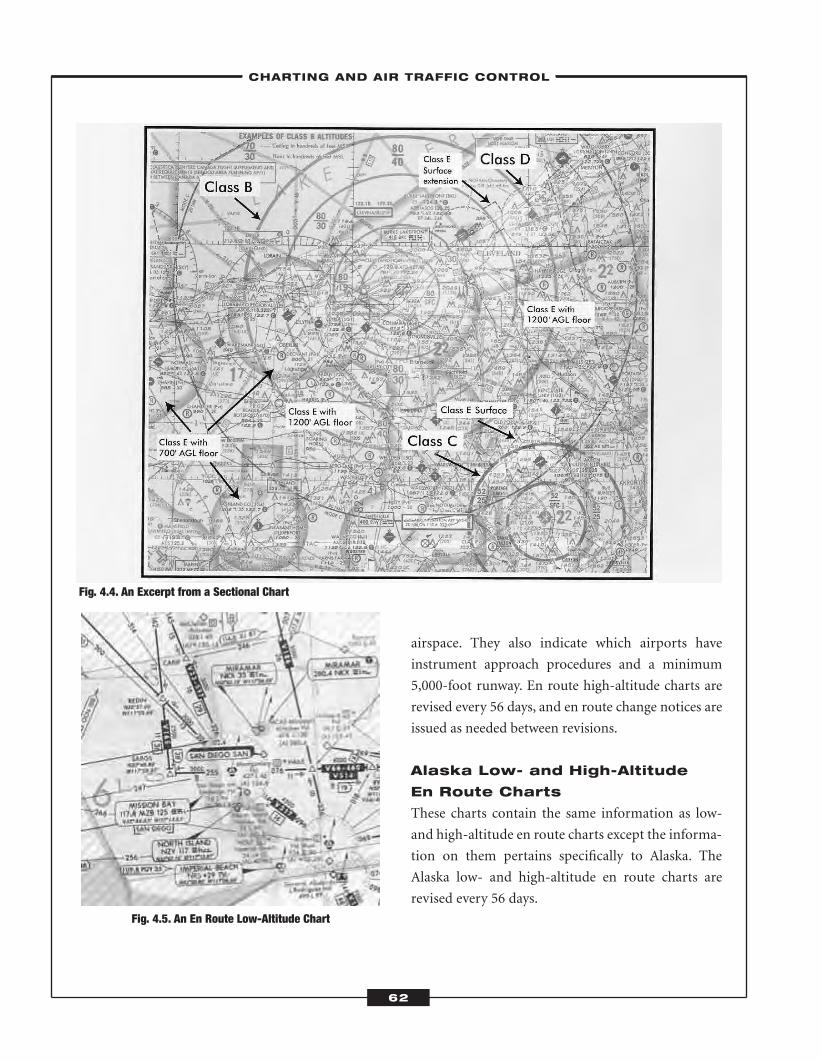
airspace. They also indicate which airports have
instrument approach procedures and a minimum
5,000-foot runway. En route high-altitude charts are
revised every 56 days, and en route change notices are
issued as needed between revisions.
Alaska Low- and High-Altitude
En Route Charts
These charts contain the same information as low-
and high-altitude en route charts except the informa-
tion on them pertains specifically to Alaska. The
Alaska low- and high-altitude en route charts are
revised every 56 days.
Fig. 4.4. An Excerpt from a Sectional Chart
Fig. 4.5. An En Route Low-Altitude Chart
–CHARTING AND AIR TRAFFIC CONTROL–
62
ATC_2008b:Layout 1 11/24/08 1:14 PM Page 62
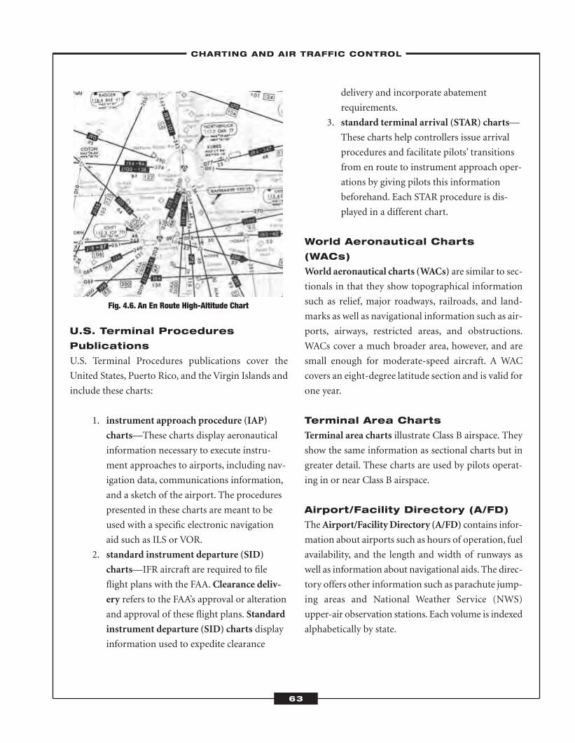
U.S. Terminal Procedures
Publications
U.S. Terminal Procedures publications cover the
United States, Puerto Rico, and the Virgin Islands and
include these charts:
1. instrument approach procedure (IAP)
charts—These charts display aeronautical
information necessary to execute instru-
ment approaches to airports, including nav-
igation data, communications information,
and a sketch of the airport. The procedures
presented in these charts are meant to be
used with a specific electronic navigation
aid such as ILS or VOR.
2. standard instrument departure (SID)
charts—IFR aircraft are required to file
flight plans with the FAA. Clearance deliv-
ery refers to the FAA’s approval or alteration
and approval of these flight plans. Standard
instrument departure (SID) charts display
information used to expedite clearance
delivery and incorporate abatement
requirements.
3. standard terminal arrival (STAR) charts—
These charts help controllers issue arrival
procedures and facilitate pilots’ transitions
from en route to instrument approach oper-
ations by giving pilots this information
beforehand. Each STAR procedure is dis-
played in a different chart.
World Aeronautical Charts
(WACs)
World aeronautical charts (WACs) are similar to sec-
tionals in that they show topographical information
such as relief, major roadways, railroads, and land-
marks as well as navigational information such as air-
ports, airways, restricted areas, and obstructions.
WACs cover a much broader area, however, and are
small enough for moderate-speed aircraft. A WAC
covers an eight-degree latitude section and is valid for
one year.
Terminal Area Charts
Terminal area charts illustrate Class B airspace. They
show the same information as sectional charts but in
greater detail. These charts are used by pilots operat-
ing in or near Class B airspace.
Airport/Facility Directory (A/FD)
TheAirport/FacilityDirectory (A/FD) contains infor-
mation about airports such as hours of operation, fuel
availability, and the length and width of runways as
well as information about navigational aids. The direc-
tory offers other information such as parachute jump-
ing areas and National Weather Service (NWS)
upper-air observation stations. Each volume is indexed
alphabetically by state.
Fig. 4.6. An En Route High-Altitude Chart
–CHARTING AND AIR TRAFFIC CONTROL–
63
ATC_2008b:Layout 1 11/24/08 1:14 PM Page 63
Information Found on Both Low- and High-Altitude En Route Charts
Routes or airways are formed in the shape of corridors and are marked with navigational aids such as VOR-
TACs. Low-altitude routes, those below 18,000 feet, are called Victor airways and are marked with the letter
V, as in V64 (pronounced Victor sixty-four). High-altitude routes, those at or above 18,000 feet, are called jet
routes and are marked with the letter J, as in J187.
Navigational aids mark the position of radio beacons and transmitters used for navigation, such as the Tac-
tical Air Navigation (TACAN), which provides bearing and distance information.
Minimum en route altitude (MEA) is the lowest altitude of a guaranteed navigational signal shown as a num-
ber along the airway.
Minimum crossing altitude (MCA) is the lowest altitude allowed because of obstacles or a possible loss of
navigational signal.
Minimum obstruction clearance altitude (MOCA) is the lowest altitude allowed between radio fixes on VOR
(VHF omnidirectional range) airways, off-airway routes, and route segments that meets obstacle clearance
requirements and assures navigational coverage within 22 NM of a VOR.
Minimum reception altitude (MRA) is the lowest altitude at which an airway intersection is identifiable by
reception of both navigational signals.
Changeover points (COPs) are points of handoff from the current navigational aid to the next navigational aid.
A COP is usually halfway between the two, but if it is not, this will be shown on the chart.
Maximum authorized altitude (MAA) is the highest altitude usable with adequate reception of navigational
signals. Above the MAA, there may be interference from other navigational aids.
64
ATC_2008b:Layout 1 11/24/08 1:14 PM Page 64
Chapter 4 Review Quiz
1–10: Circle the correct answer.
1. En route high-altitude charts are similar to enroute low-altitude charts but are for use at or
above
a. 10,000 feet.
b. 16,000 feet.
c. 18,000 feet.
d. 22,000 feet.
2. The chart commonly used for visual navigationis the
a. sectional chart.
b. world aeronautical chart (WAC).
c. standard terminal arrival (STAR) chart.
d. instrument approach procedure (IAP) chart.
3. The letter “V” in the route name V64 suggeststhat the route is
a. oriented east-west.
b. oriented north-south.
c. a low-altitude airway.
d. a high-altitude airway.
4. The lowest altitude allowed because of obstaclesis called the
a. minimum reception altitude (MRA).
b. maximum authorized altitude (MAA).
c. minimum crossing altitude (MCA).
d. minimum en route altitude (MEA).
5. Which statement about instrument approachprocedure (IAP) charts is true?
a. IAP charts show information that helps pilots
execute instrument approaches to airports.
b. IAP charts guide air traffic and show routes
for noise abatement.
c. IAP charts simplify clearance delivery
procedures and help pilots clear obstacles
safely.
d. IAP charts help pilots transition from an en
route instrument flying mode to instrument
approach operations.
6. What kind of chart shows roads, railroads, land-marks, and topography on a small scale that is
suitable for moderate-speed aircraft?
a. en route low-altitude chart
b. world aeronautical chart (WAC)
c. terminal area chart
d. instrument approach procedure (IAP) chart
7. Which of the following would most likely becharted as an obstruction on a sectional chart?
a. a skyscraper that is 300 feet AGL
b. a warehouse that is 600 feet long
c. a bridge that is 50 feet AGL
d. a mountain that is 250 feet AGL
8. A steep contour on a sectional chart would beindicated by lines that are
a. far apart.
b. light green.
c. close together.
d. shaded.
–CHARTING AND AIR TRAFFIC CONTROL–
65
ATC_2008b:Layout 1 11/24/08 1:14 PM Page 65
9. The maximum elevation figure (MEF) on a sec-tional is 9,200 feet. How would this number
appear on the chart?
a. 9.2
b. 92
c. 9200
d. 920
10.Which U.S. Terminal Procedures publication isused to expedite clearance delivery?
a. instrument approach procedure (IAP) chart
b. standard instrument departure (SID) chart
c. clearance delivery (CD) chart
d. standard terminal arrival (STAR) chart
Check your answers on page 288.
–CHARTING AND AIR TRAFFIC CONTROL–
66
ATC_2008b:Layout 1 11/24/08 1:14 PM Page 66
As you learned in Chapter 1, the Analogy Test measures your ability to reason well.As you can imag-
ine, air traffic controllers must be able to formulate scenarios and quickly draw conclusions based
on what they see. An analogy is a comparison of two words or pictures that somehow relate to
each other. The Analogy Test will present you with a complete analogy, and you need to determine the relation-
ship between the twowords or symbols in this analogy.Youwill then be presented with half an analogy that, when
completed, should have the same relationship as the first. You need to choose the answer choice that best com-
pletes the second analogy.
� The Analogy Test
The Analogy Test will present you with 30 word analogies and 27 visual analogies, for a total of 57 questions.
Though you will actually take this test on a computer, this chapter of the book will help prepare you for what
you will see on the screen.
Analogies
CHAPTER SUMMARYThe Analogy Test is one of seven cognitive tests on the AT-SAT. On
this test, you will answer questions about word and visual analogies.
Each question has three boxes. The first box contains a complete
analogy. The second box contains part of an analogy and a question
mark, and the third box contains four answer options.
5C H A P T E R
67
ATC_2008b:Layout 1 11/24/08 1:14 PM Page 67
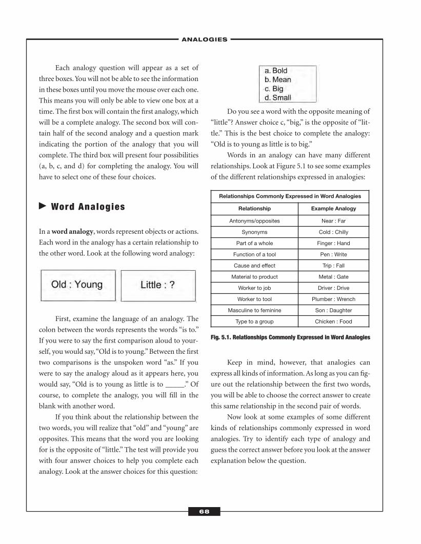
Each analogy question will appear as a set of
three boxes.You will not be able to see the information
in these boxes until youmove themouse over each one.
This means you will only be able to view one box at a
time. The first box will contain the first analogy,which
will be a complete analogy. The second box will con-
tain half of the second analogy and a question mark
indicating the portion of the analogy that you will
complete. The third box will present four possibilities
(a, b, c, and d) for completing the analogy. You will
have to select one of these four choices.
� Word Analogies
In aword analogy, words represent objects or actions.
Each word in the analogy has a certain relationship to
the other word. Look at the following word analogy:
First, examine the language of an analogy. The
colon between the words represents the words “is to.”
If you were to say the first comparison aloud to your-
self, you would say,“Old is to young.”Between the first
two comparisons is the unspoken word “as.” If you
were to say the analogy aloud as it appears here, you
would say, “Old is to young as little is to _____.” Of
course, to complete the analogy, you will fill in the
blank with another word.
If you think about the relationship between the
two words, you will realize that “old” and “young” are
opposites. This means that the word you are looking
for is the opposite of “little.” The test will provide you
with four answer choices to help you complete each
analogy. Look at the answer choices for this question:
Do you see a word with the opposite meaning of
“little”? Answer choice c, “big,” is the opposite of “lit-
tle.” This is the best choice to complete the analogy:
“Old is to young as little is to big.”
Words in an analogy can have many different
relationships. Look at Figure 5.1 to see some examples
of the different relationships expressed in analogies:
Fig. 5.1. Relationships Commonly Expressed in Word Analogies
Keep in mind, however, that analogies can
express all kinds of information.As long as you can fig-
ure out the relationship between the first two words,
you will be able to choose the correct answer to create
this same relationship in the second pair of words.
Now look at some examples of some different
kinds of relationships commonly expressed in word
analogies. Try to identify each type of analogy and
guess the correct answer before you look at the answer
explanation below the question.
Relationships Commonly Expressed in Word Analogies
Relationship Example Analogy
Antonyms/opposites Near : Far
Synonyms Cold : Chilly
Part of a whole Finger : Hand
Function of a tool Pen : Write
Cause and effect Trip : Fall
Material to product Metal : Gate
Worker to job Driver : Drive
Worker to tool Plumber : Wrench
Masculine to feminine Son : Daughter
Type to a group Chicken : Food
–ANALOGIES–
68
ATC_2008b:Layout 1 11/24/08 1:14 PM Page 68
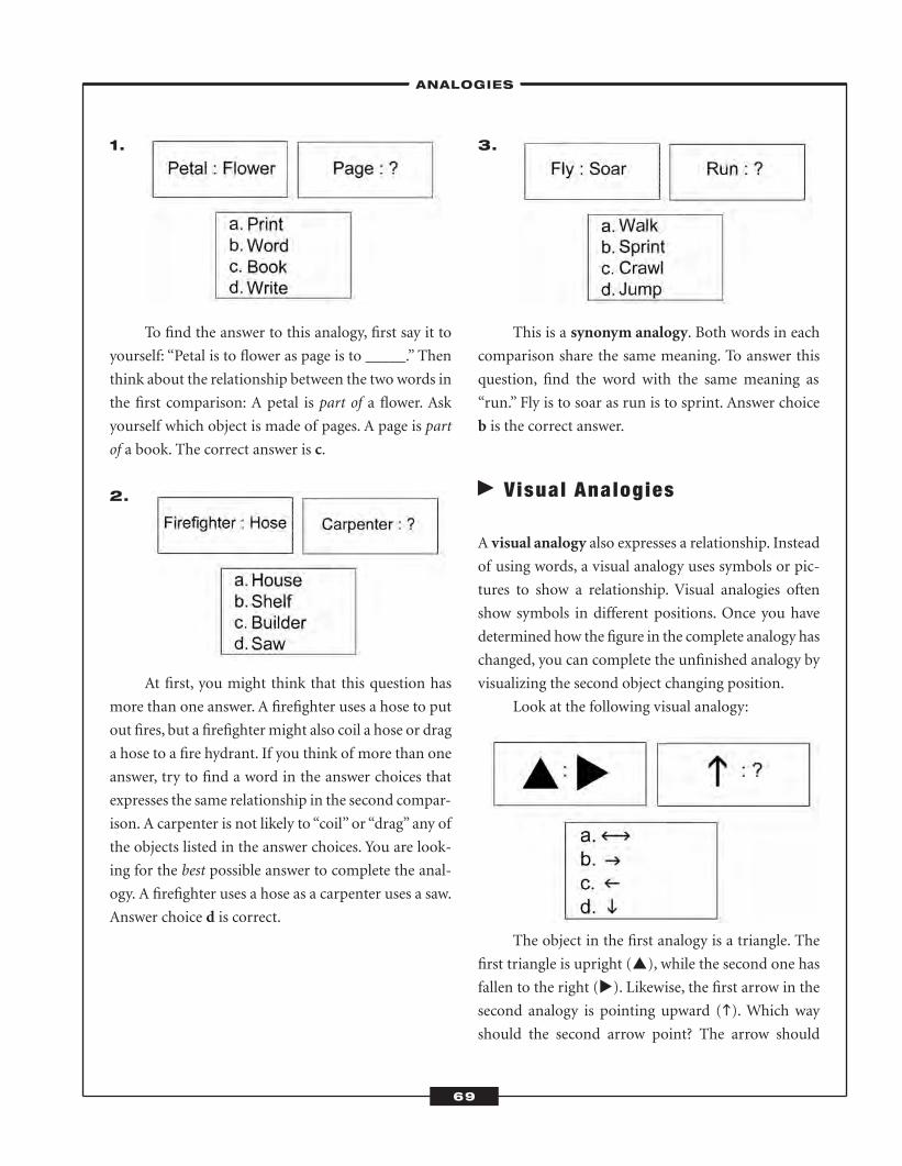
1.
To find the answer to this analogy, first say it to
yourself: “Petal is to flower as page is to _____.” Then
think about the relationship between the two words in
the first comparison: A petal is part of a flower. Ask
yourself which object is made of pages. A page is part
of a book. The correct answer is c.
2.
At first, you might think that this question has
more than one answer. A firefighter uses a hose to put
out fires, but a firefightermight also coil a hose or drag
a hose to a fire hydrant. If you think of more than one
answer, try to find a word in the answer choices that
expresses the same relationship in the second compar-
ison. A carpenter is not likely to “coil” or “drag” any of
the objects listed in the answer choices. You are look-
ing for the best possible answer to complete the anal-
ogy. A firefighter uses a hose as a carpenter uses a saw.
Answer choice d is correct.
3.
This is a synonym analogy. Both words in each
comparison share the same meaning. To answer this
question, find the word with the same meaning as
“run.” Fly is to soar as run is to sprint. Answer choice
b is the correct answer.
� Visual Analogies
A visual analogy also expresses a relationship. Instead
of using words, a visual analogy uses symbols or pic-
tures to show a relationship. Visual analogies often
show symbols in different positions. Once you have
determined how the figure in the complete analogy has
changed, you can complete the unfinished analogy by
visualizing the second object changing position.
Look at the following visual analogy:
The object in the first analogy is a triangle. The
first triangle is upright (�), while the second one has
fallen to the right (�). Likewise, the first arrow in the
second analogy is pointing upward (�). Which way
should the second arrow point? The arrow should
–ANALOGIES–
69
ATC_2008b:Layout 1 11/24/08 1:14 PM Page 69
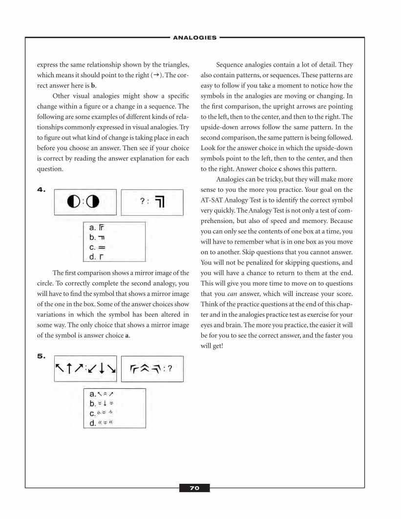
express the same relationship shown by the triangles,
whichmeans it should point to the right (�). The cor-
rect answer here is b.
Other visual analogies might show a specific
change within a figure or a change in a sequence. The
following are some examples of different kinds of rela-
tionships commonly expressed in visual analogies. Try
to figure out what kind of change is taking place in each
before you choose an answer. Then see if your choice
is correct by reading the answer explanation for each
question.
4.
The first comparison shows amirror image of the
circle. To correctly complete the second analogy, you
will have to find the symbol that shows amirror image
of the one in the box. Some of the answer choices show
variations in which the symbol has been altered in
some way. The only choice that shows a mirror image
of the symbol is answer choice a.
5.
Sequence analogies contain a lot of detail. They
also contain patterns, or sequences. These patterns are
easy to follow if you take a moment to notice how the
symbols in the analogies are moving or changing. In
the first comparison, the upright arrows are pointing
to the left, then to the center, and then to the right. The
upside-down arrows follow the same pattern. In the
second comparison, the same pattern is being followed.
Look for the answer choice in which the upside-down
symbols point to the left, then to the center, and then
to the right. Answer choice c shows this pattern.
Analogies can be tricky, but they will make more
sense to you the more you practice. Your goal on the
AT-SAT Analogy Test is to identify the correct symbol
very quickly. TheAnalogy Test is not only a test of com-
prehension, but also of speed and memory. Because
you can only see the contents of one box at a time, you
will have to remember what is in one box as you move
on to another. Skip questions that you cannot answer.
You will not be penalized for skipping questions, and
you will have a chance to return to them at the end.
This will give you more time to move on to questions
that you can answer, which will increase your score.
Think of the practice questions at the end of this chap-
ter and in the analogies practice test as exercise for your
eyes and brain. Themore you practice, the easier it will
be for you to see the correct answer, and the faster you
will get!
–ANALOGIES–
70
ATC_2008b:Layout 1 11/24/08 1:14 PM Page 70
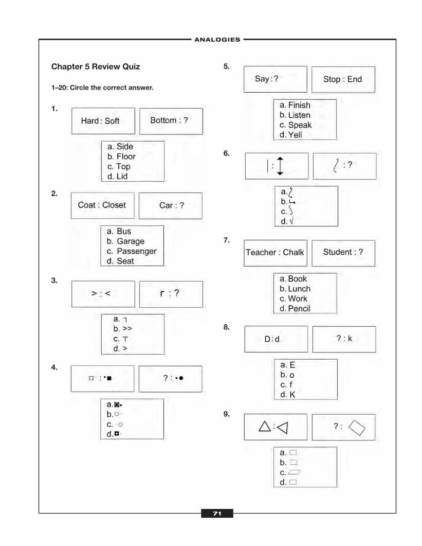
Chapter 5 Review Quiz
1–20: Circle the correct answer.
1.
2.
3.
4.
5.
6.
7.
8.
9.
–ANALOGIES–
71
ATC_2008b:Layout 1 11/24/08 1:14 PM Page 71
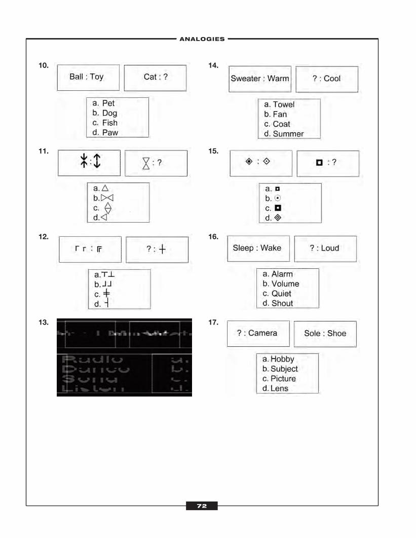
10.
11.
12.
13.
14.
15.
16.
17.
–ANALOGIES–
72
ATC_2008b:Layout 1 11/24/08 1:14 PM Page 72
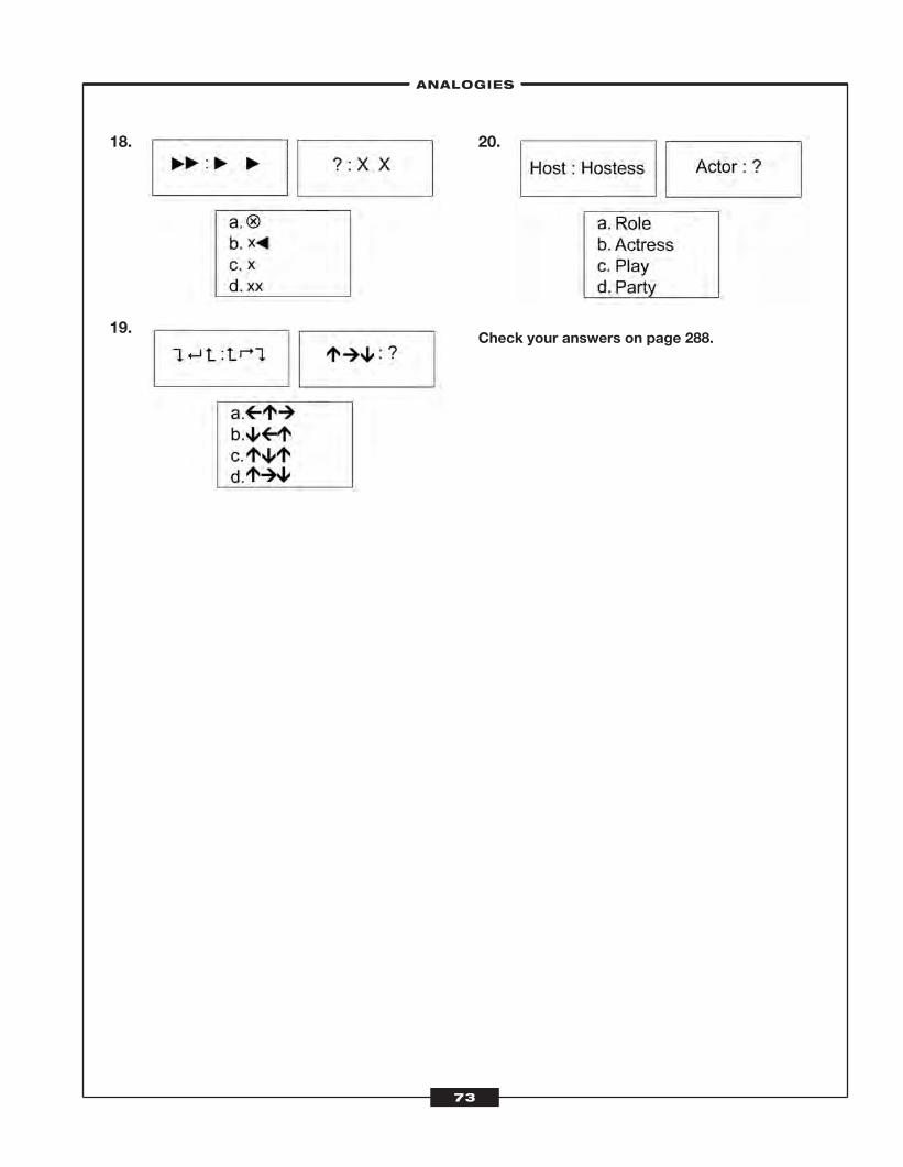
18.
19.
20.
Check your answers on page 288.
–ANALOGIES–
73
ATC_2008b:Layout 1 11/24/08 1:14 PM Page 73

ATC_2008b:Layout 1 11/24/08 1:14 PM Page 74
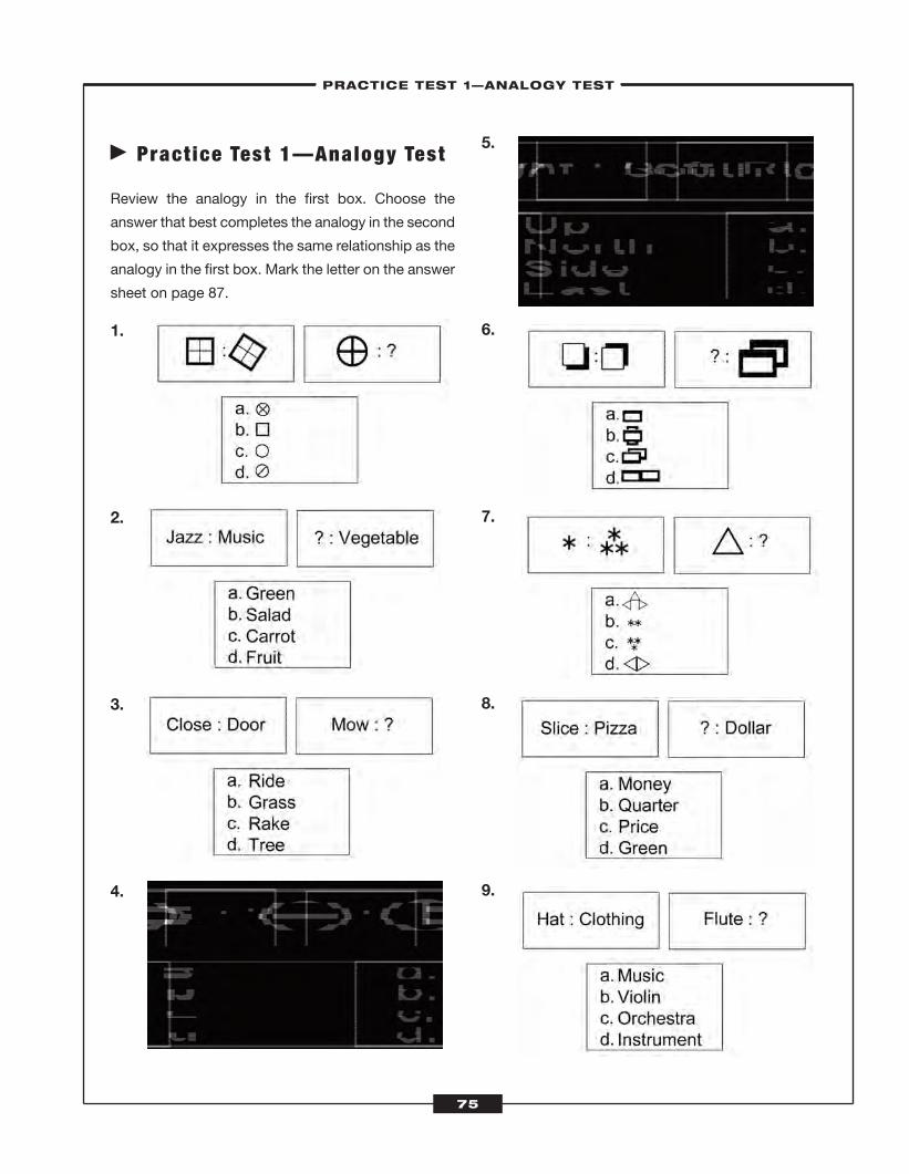
� Pract ice Test 1—Analogy Test
Review the analogy in the first box. Choose the
answer that best completes the analogy in the second
box, so that it expresses the same relationship as the
analogy in the first box. Mark the letter on the answer
sheet on page 87.
1.
2.
3.
4.
5.
6.
7.
8.
9.
–PRACTICE TEST 1—ANALOGY TEST–
75
ATC_2008b:Layout 1 11/24/08 1:14 PM Page 75
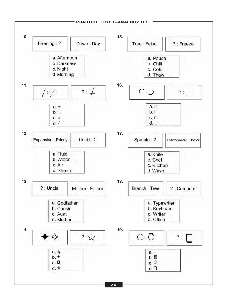
10.
11.
12.
13.
14.
15.
16.
17.
18.
19.
–PRACTICE TEST 1—ANALOGY TEST–
76
ATC_2008b:Layout 1 11/24/08 1:14 PM Page 76
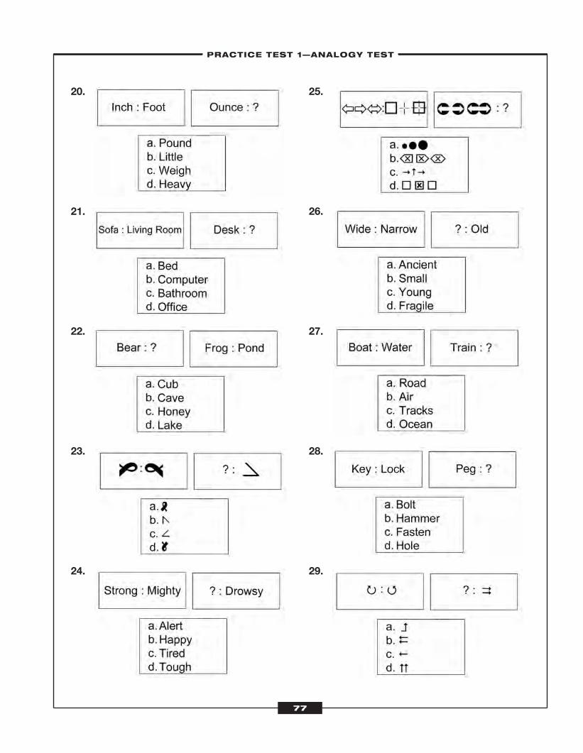
20.
21.
22.
23.
24.
25.
26.
27.
28.
29.
–PRACTICE TEST 1—ANALOGY TEST–
77
ATC_2008b:Layout 1 11/24/08 1:14 PM Page 77
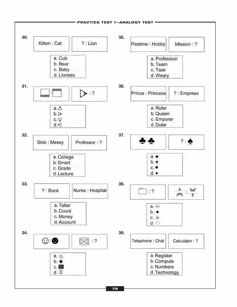
30.
31.
32.
33.
34.
35.
36.
37.
38.
39.
–PRACTICE TEST 1—ANALOGY TEST––PRACTICE TEST 1—ANALOGY TEST–
78
ATC_2008b:Layout 1 11/24/08 1:14 PM Page 78
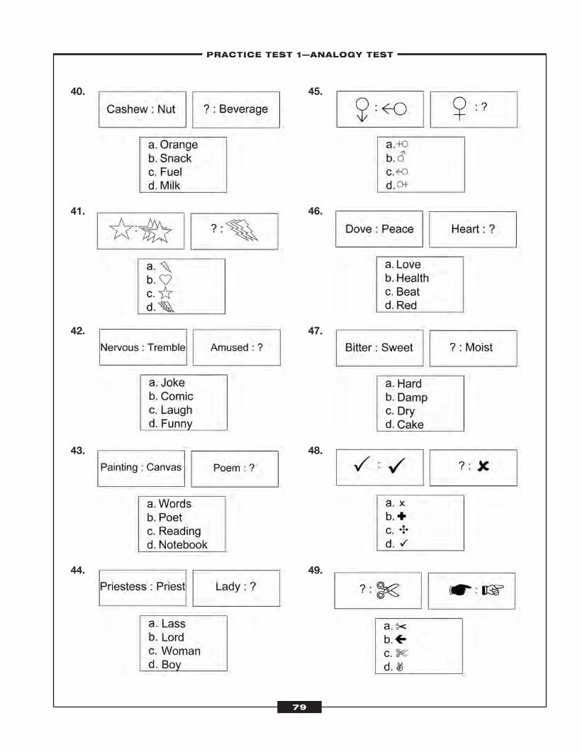
40.
41.
42.
43.
44.
45.
46.
47.
48.
49.
–PRACTICE TEST 1—ANALOGY TEST––PRACTICE TEST 1—ANALOGY TEST–
79
ATC_2008b:Layout 1 11/24/08 1:14 PM Page 79
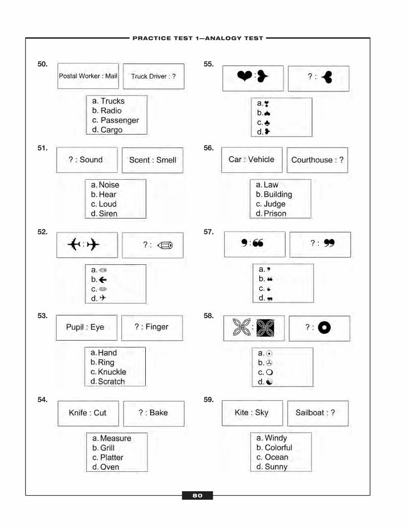
50.
51.
52.
53.
54.
55.
56.
57.
58.
59.
–PRACTICE TEST 1—ANALOGY TEST–
80
ATC_2008b:Layout 1 11/24/08 1:14 PM Page 80
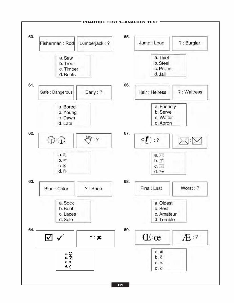
60.
61.
62.
63.
64.
65.
66.
67.
68.
69.
–PRACTICE TEST 1—ANALOGY TEST–
81
ATC_2008b:Layout 1 11/24/08 1:14 PM Page 81
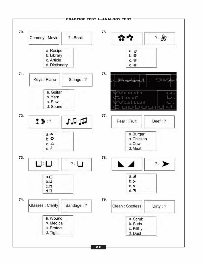
70.
71.
72.
73.
74.
75.
76.
77.
78.
79.
–PRACTICE TEST 1—ANALOGY TEST–
82
ATC_2008b:Layout 1 11/24/08 1:15 PM Page 82
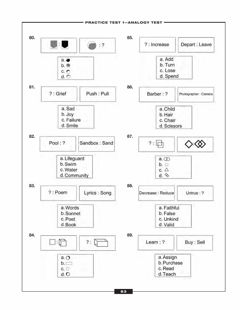
80.
81.
82.
83.
84.
85.
86.
87.
88.
89.
–PRACTICE TEST 1—ANALOGY TEST–
83
ATC_2008b:Layout 1 11/24/08 1:15 PM Page 83
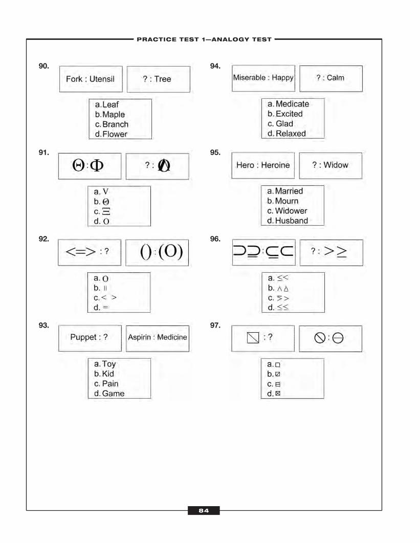
90.
91.
92.
93.
94.
95.
96.
97.
–PRACTICE TEST 1—ANALOGY TEST–
84
ATC_2008b:Layout 1 11/24/08 1:15 PM Page 84
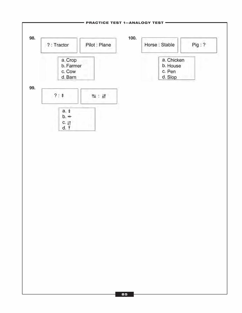
98.
99.
100.
–PRACTICE TEST 1—ANALOGY TEST–
85
ATC_2008b:Layout 1 11/24/08 1:15 PM Page 85

ATC_2008b:Layout 1 11/24/08 1:15 PM Page 86
Practice Test 1—Analogy Test
–LEARNINGEXPRESS ANSWER SHEET–
87
1. a b c d
2. a b c d
3. a b c d
4. a b c d
5. a b c d
6. a b c d
7. a b c d
8. a b c d
9. a b c d
10. a b c d
11. a b c d
12. a b c d
13. a b c d
14. a b c d
15. a b c d
16. a b c d
17. a b c d
18. a b c d
19. a b c d
20. a b c d
21. a b c d
22. a b c d
23. a b c d
24. a b c d
25. a b c d
26. a b c d
27. a b c d
28. a b c d
29. a b c d
30. a b c d
31. a b c d
32. a b c d
33. a b c d
34. a b c d
35. a b c d
36. a b c d
37. a b c d
38. a b c d
39. a b c d
40. a b c d
41. a b c d
42. a b c d
43. a b c d
44. a b c d
45. a b c d
46. a b c d
47. a b c d
48. a b c d
49. a b c d
50. a b c d
51. a b c d
52. a b c d
53. a b c d
54. a b c d
55. a b c d
56. a b c d
57. a b c d
58. a b c d
59. a b c d
60. a b c d
61. a b c d
62. a b c d
63. a b c d
64. a b c d
65. a b c d
66. a b c d
67. a b c d
68. a b c d
69. a b c d
70. a b c d
71. a b c d
72. a b c d
73. a b c d
74. a b c d
75. a b c d
76. a b c d
77. a b c d
78. a b c d
79. a b c d
80. a b c d
81. a b c d
82. a b c d
83. a b c d
84. a b c d
85. a b c d
86. a b c d
87. a b c d
88. a b c d
89. a b c d
90. a b c d
91. a b c d
92. a b c d
93. a b c d
94. a b c d
95. a b c d
96. a b c d
97. a b c d
98. a b c d
99. a b c d
100. a b c d
ATC_2008b:Layout 1 11/24/08 1:15 PM Page 87
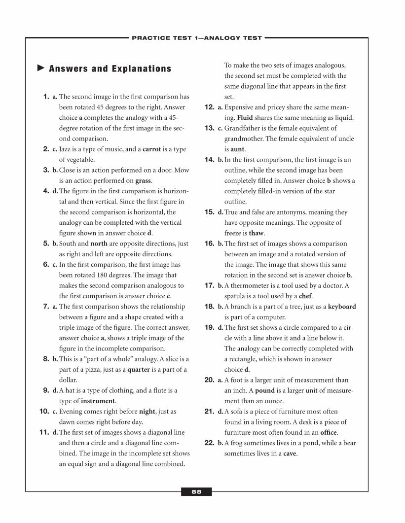
� Answers and Explanat ions
1. a. The second image in the first comparison hasbeen rotated 45 degrees to the right. Answer
choice a completes the analogy with a 45-
degree rotation of the first image in the sec-
ond comparison.
2. c. Jazz is a type of music, and a carrot is a typeof vegetable.
3. b.Close is an action performed on a door. Mowis an action performed on grass.
4. d.The figure in the first comparison is horizon-tal and then vertical. Since the first figure in
the second comparison is horizontal, the
analogy can be completed with the vertical
figure shown in answer choice d.
5. b. South and north are opposite directions, justas right and left are opposite directions.
6. c. In the first comparison, the first image hasbeen rotated 180 degrees. The image that
makes the second comparison analogous to
the first comparison is answer choice c.
7. a. The first comparison shows the relationshipbetween a figure and a shape created with a
triple image of the figure. The correct answer,
answer choice a, shows a triple image of the
figure in the incomplete comparison.
8. b.This is a “part of a whole” analogy. A slice is apart of a pizza, just as a quarter is a part of a
dollar.
9. d.A hat is a type of clothing, and a flute is atype of instrument.
10. c. Evening comes right before night, just asdawn comes right before day.
11. d.The first set of images shows a diagonal lineand then a circle and a diagonal line com-
bined. The image in the incomplete set shows
an equal sign and a diagonal line combined.
To make the two sets of images analogous,
the second set must be completed with the
same diagonal line that appears in the first
set.
12. a. Expensive and pricey share the same mean-ing. Fluid shares the same meaning as liquid.
13. c. Grandfather is the female equivalent ofgrandmother. The female equivalent of uncle
is aunt.
14. b. In the first comparison, the first image is anoutline, while the second image has been
completely filled in. Answer choice b shows a
completely filled-in version of the star
outline.
15. d.True and false are antonyms, meaning theyhave opposite meanings. The opposite of
freeze is thaw.
16. b.The first set of images shows a comparisonbetween an image and a rotated version of
the image. The image that shows this same
rotation in the second set is answer choice b.
17. b.A thermometer is a tool used by a doctor. Aspatula is a tool used by a chef.
18. b.A branch is a part of a tree, just as a keyboardis part of a computer.
19. d.The first set shows a circle compared to a cir-cle with a line above it and a line below it.
The analogy can be correctly completed with
a rectangle, which is shown in answer
choice d.
20. a. A foot is a larger unit of measurement thanan inch. A pound is a larger unit of measure-
ment than an ounce.
21. d.A sofa is a piece of furniture most oftenfound in a living room. A desk is a piece of
furniture most often found in an office.
22. b.A frog sometimes lives in a pond, while a bearsometimes lives in a cave.
–PRACTICE TEST 1—ANALOGY TEST–
88
ATC_2008b:Layout 1 11/24/08 1:15 PM Page 88
23. c. The first comparison shows a mirror imageof two figures. Answer choice c shows the
mirror image of the figure in the second
comparison.
24. c. Strong and mighty have the same meaning.The word with the same meaning as drowsy
is tired.
25. b.The two sets of figures in the first comparisoneach show two separate figures and then an
image of the combined figures, as does the
first set of figures in the incomplete compari-
son. To complete the analogy, answer choice
b shows two separate figures and then an
image of the combined figures.
26. c.Wide is the opposite of narrow, as young isthe opposite of old.
27. c. A boat travels on the water, and a train travelson tracks.
28. d.A key fits into a lock as a peg fits into a hole.29. b.The first comparison shows arrows pointing
in two different directions. The arrows that
point opposite the ones in the incomplete
comparison are shown in answer choice b.
30. a. A kitten matures to become a cat, while a cubmatures to become a lion.
31. d.The second image in the first comparison hasbeen rotated 180 degrees. Answer choice d
completes the analogy with a 180-degree
rotation of the first image in the second
comparison.
32. b.A slob is a person who is messy, while a pro-fessor is a person who is smart.
33. a. A teller works in a bank, and a nurse works
in a hospital.
34. c. The first comparison shows two identicalimages with opposite colors. Answer choice c
completes the analogy with an identical shape
with reverse colors of the first image in the
incomplete comparison.
35. c. These analogies show synonyms, or wordswith the same meaning. A pastime is a hobby,
and a mission is a task.
36. c. This is a “masculine to feminine” analogy. Aprince is to a princess as an emperor is to an
empress.
37. b.The images in the first comparison are identi-cal. Answer choice b completes the analogy
with a shape that is identical to the image in
the second comparison.
38. d.The second image in the second comparisonhas been turned 180 degrees. Answer choice d
completes the analogy with a 180-degree
rotation of the first image in the first
comparison.
39. b.A telephone is a device used to chat withsomeone. A calculator is a device used to
compute something.
40. d.This is a “type to a group” analogy. A cashewis a type of nut.Milk is a type of beverage.
41. a. The first comparison shows an image andthen a triple version of the image. Answer
choice a completes the analogy by showing
the single image that is tripled in the second
comparison.
42. c. This is a “cause and effect” analogy. Feelingnervous might cause a person to tremble,
while feeling amused might cause a person
to laugh.
43. d.A painting is often created on a canvas, whilea poem is often created in a notebook.
44. b.A priestess is the title for a female priest. Ladyis an English title of honor for a woman. The
male equivalent is lord.
45. a. The second image in the first comparison hasbeen rotated 90 degrees clockwise. Answer
choice a completes the analogy with a 90-
degree clockwise rotation of the first image in
the second comparison.
–PRACTICE TEST 1—ANALOGY TEST–
89
ATC_2008b:Layout 1 11/24/08 1:15 PM Page 89
46. a. The dove is a symbol that stands for peace,and a heart is a symbol that represents love.
47. c. Bitter and sweet are antonyms, or opposites.The word with the opposite meaning of
moist is dry.
48. a. The images in the first comparison show asymbol and then a thicker version of the
symbol. Answer choice a is a thinner version
of the symbol in the second comparison.
49. a. The images in the second comparison show adark image and a more detailed lighter image.
Answer choice a completes the analogy with a
dark version of the detailed image in the first
comparison.
50. d.A postal worker’s job is to deliver mail. Atruck driver’s job is to deliver cargo.
51. a. Scent is a synonym for smell.Noise is a syn-onym for sound.
52. c. The second image in the first comparison hasbeen rotated 180 degrees. Answer choice c
completes the analogy with a 180-degree
rotation of the second image in the second
comparison.
53. c. This is a “part of a whole” analogy. A pupil ispart of an eye, just as a knuckle is part of a
finger.
54. d.A knife is a tool used to cut, while an oven isa tool used to bake.
55. b.The second image in the first comparison hasbeen rotated 90 degrees counterclockwise.
Answer choice b completes the analogy with
a 90-degree rotation of the second image in
the second comparison.
56. b.A car is a type of vehicle. A courthouse is atype of building.
57. c. The second image in the first comparison hasbeen rotated 180 degrees and doubled.
Answer choice c completes the analogy with a
single version of the second image in the sec-
ond comparison. The image has also gone
through a 180-degree rotation.
58. a. The images in the first comparison are identi-cal except that their coloring is reversed.
Answer choice a completes the analogy with
an identical shape in which the color has
been reversed.
59. c. A kite can be found in the sky, just as a sail-boat can be found in the ocean.
60. a. A fisherman uses a rod to catch fish, while alumberjack uses a saw to cut down trees.
61. d.Safe and dangerous are antonyms. The oppo-site of early is late.
62. c. The images in the first comparison are identi-cal except that one image is flipped horizon-
tally. Answer choice d completes the analogy
with an identical shape to the first image in
the second comparison that is flipped
horizontally.
63. b.Blue is a type of color, and a boot is a type ofshoe.
64. b.The first symbol in the first comparison iscompared to a version of the symbol within a
box. Answer choice b completes the analogy
by showing the symbol in the first compari-
son within a box.
65. a. Jump and leap are synonyms. Thief and bur-glar also have the same meaning.
66. c. Heir is the masculine form of the wordheiress, just as waiter is the masculine form
of the word waitress.
67. b.The images in the second comparison areidentical. Answer choice b completes the
analogy with a shape that is identical to the
first image in the first comparison.
68. b.First and last have opposite meanings. Theword with the opposite meaning of worst is
best.
–PRACTICE TEST 1—ANALOGY TEST–
90
ATC_2008b:Layout 1 11/24/08 1:15 PM Page 90
69. a. The images in the first comparison show acapital symbol and a lowercase symbol.
Answer choice a completes the analogy with
the lowercase version of the symbol in the
second comparison.
70. d.A comedy is one type of movie, just as a dic-tionary is one type of book.
71. a. Keys are part of a piano just as strings arepart of a guitar.
72. a. The first two images in the second sequencehave been combined to create the third
image. The image that completes the
sequence correctly is answer choice a, the
clover with three petals.
73. b.The images in the first comparison are identi-cal. Answer choice b completes the analogy
with a shape that is identical to the second
image in the second comparison.
74. c. The purpose of glasses is to clarify vision. Thepurpose of a bandage is to protect a wound.
75. c. The first comparison shows a flower and anidentical flower with one petal removed. The
second image in the second comparison
shows a flower with one petal removed.
Answer choice c is correct because it shows
the entire flower.
76. b.An artist creates sketches, and a chef createsdishes.
77. d.A pear is one type of fruit. Beef is one type ofmeat.
78. b.The images in the first comparison are identi-cal except that one image is facing right and
one image is facing left. Answer choice b
completes the analogy with an identical shape
that is facing in the opposite direction of the
second image in the comparison.
79. c. Clean and spotless are synonyms. They sharethe same meaning. Filthy has the same
meaning as dirty.
80. a. The images in the first comparison are identi-cal, but the second image is darker than the
first. Answer choice a completes the second
comparison with an identical shape in which
the second image is darker than the first.
81. b. Joy and grief are opposite emotions, just aspush and pull are opposite actions.
82. c. A pool is filled with water, and a sandbox isfull of sand.
83. a. A poem is made up of words, as a song ismade up of lyrics.
84. b.The second image in the first comparison is athree-dimensional version of the first image.
Answer choice b completes the analogy with
a two-dimensional version of the second
image in the second comparison.
85. a. Add is a synonym of increase, just as depart isa synonym of leave.
86. d.A barber uses scissors as a photographer usesa camera.
87. b.The second comparison shows a vertical fig-ure compared to a horizontal image of the
figure overlapped with a second horizontal
image. The vertical rectangle seen in answer
choice b completes the analogy.
88. b.Decrease and reduce share the same meaning.Untrue and false also share the same
meaning.
89. d.Learn and teach are opposite actions, as arebuy and sell.
90. b.A fork is a type of utensil, as amaple is a type
of tree.
91. b.The first comparison shows a horizontalshape inside of an oval compared to a larger,
vertical version of the image on the outside of
the oval. Answer choice b shows a small, hori-
zontal version of the large shape on the out-
side of the oval in the incomplete
comparison.
–PRACTICE TEST 1—ANALOGY TEST–
91
ATC_2008b:Layout 1 11/24/08 1:15 PM Page 91
92. c. The second comparison shows two oppositeimages, and then the same images with a
shape between them. Answer choice c, which
shows two opposite images without a shape
between them, completes the analogy.
93. a. A puppet is a type of toy. Aspirin is a type ofmedicine.
94. b.Miserable and happy are opposite emotions,as are excited and calm.
95. c. Hero is the masculine form of heroine, just aswidower is the masculine form of widow.
96. a. The first comparison shows two versions ofan image and the same image with a line
underneath. Answer choice a completes the
second comparison to make the two sets
analogous.
97. c. The second comparison shows a circle with adiagonal line running through it compared to
a circle with a horizontal line running
through it. A square with a horizontal line
running through it will complete the analogy;
this image is presented in answer choice c.
98. b.A farmer drives a tractor just as a pilot flies a
plane.
99. b.The second image in the second comparisonhas been rotated 90 degrees. To make the first
comparison analogous, answer choice b is
correct.
100. c. A horse lives in a stable, and a pig lives in apen.
–PRACTICE TEST 1—ANALOGY TEST–
92
ATC_2008b:Layout 1 11/24/08 1:15 PM Page 92
Since controllers must be able to perform mathematical calculations, two tests on the AT-SAT are
about math: the Angles Test and the Applied Math Test. You will take these tests on a computer,
and you will not be able to use a pencil and paper to calculate your answers. For the Angles Test,
you will need to be able to recognize themeasurement of angles without using a protractor. The Angles Test con-
tains 30 multiple-choice questions. For the Applied Math Test, you will have to calculate distance problems as
quickly as you can.While this might seem difficult, it will be much easier if you practice, practice, practice! The
Applied Math Test contains 30 multiple-choice questions, but the first five are practice items and are not scored.
� Angles
You probably learned about angles back in elementary school and then again in high school.When two raysmeet
and share an endpoint, they form an angle.
Angles andApplied Math
CHAPTER SUMMARYThe Angles Test and the Applied Math Test are cognitive tests on the
AT-SAT. For some questions on the Angles Test, you will be shown an
angle and asked to choose the correct measurement. For other ques-
tions, you will have to click on the angle that is a given measurement.
On the Applied Math Test, you will be asked questions about the
movement of aircraft. You will have to calculate time, distance, and
speed.
6C H A P T E R
93
ATC_2008b:Layout 1 11/24/08 1:15 PM Page 93
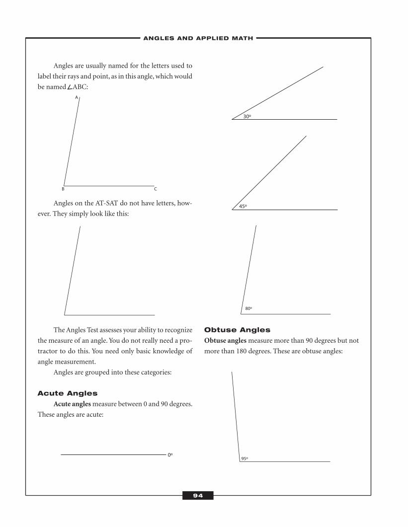
Angles are usually named for the letters used to
label their rays and point, as in this angle, which would
be named ABC:
Angles on the AT-SAT do not have letters, how-
ever. They simply look like this:
TheAngles Test assesses your ability to recognize
the measure of an angle. You do not really need a pro-
tractor to do this. You need only basic knowledge of
angle measurement.
Angles are grouped into these categories:
Acute Angles
Acute anglesmeasure between 0 and 90 degrees.
These angles are acute:
Obtuse Angles
Obtuse anglesmeasure more than 90 degrees but not
more than 180 degrees. These are obtuse angles:
A
B C
0º
30º
80º
95º
45º
–ANGLES AND APPLIED MATH–
94
ATC_2008b:Layout 1 11/24/08 1:15 PM Page 94
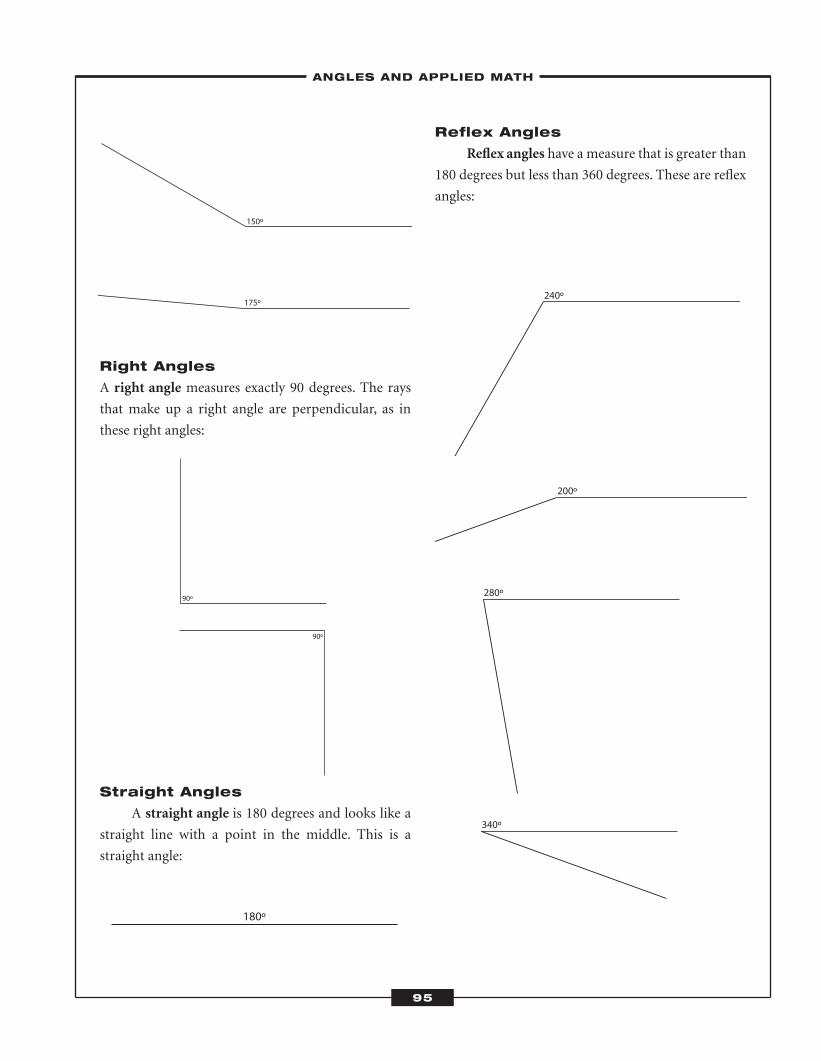
Right Angles
A right angle measures exactly 90 degrees. The rays
that make up a right angle are perpendicular, as in
these right angles:
Straight Angles
A straight angle is 180 degrees and looks like a
straight line with a point in the middle. This is a
straight angle:
Reflex Angles
Reflex angles have a measure that is greater than
180 degrees but less than 360 degrees. These are reflex
angles:
180º
240º
200º
280º
340º
150º
175º
90º
90º
–ANGLES AND APPLIED MATH–
95
ATC_2008b:Layout 1 11/24/08 1:15 PM Page 95
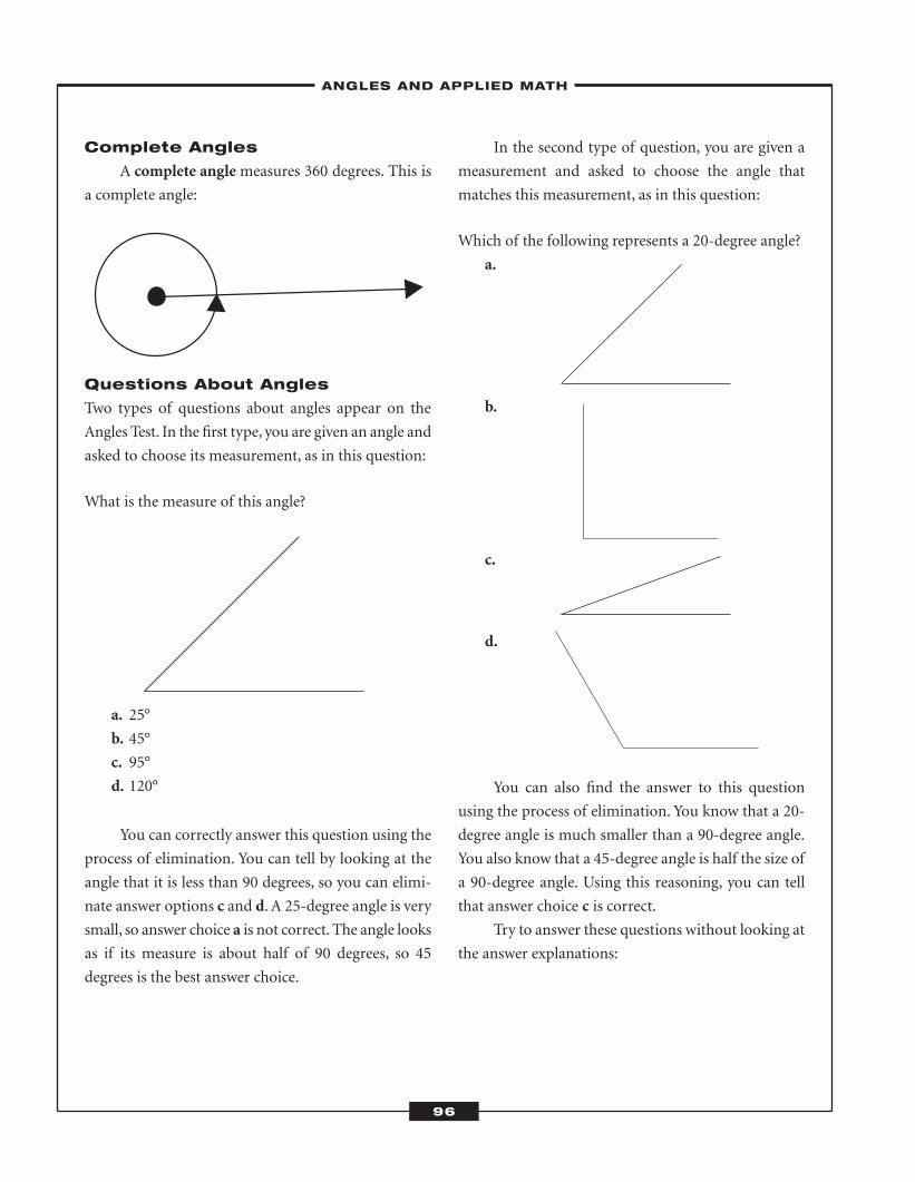
Complete Angles
A complete anglemeasures 360 degrees. This is
a complete angle:
Questions About Angles
Two types of questions about angles appear on the
Angles Test. In the first type, you are given an angle and
asked to choose its measurement, as in this question:
What is the measure of this angle?
a. 25°
b. 45°
c. 95°
d. 120°
You can correctly answer this question using the
process of elimination. You can tell by looking at the
angle that it is less than 90 degrees, so you can elimi-
nate answer options c and d. A 25-degree angle is very
small, so answer choice a is not correct. The angle looks
as if its measure is about half of 90 degrees, so 45
degrees is the best answer choice.
In the second type of question, you are given a
measurement and asked to choose the angle that
matches this measurement, as in this question:
Which of the following represents a 20-degree angle?
a.
b.
c.
d.
You can also find the answer to this question
using the process of elimination. You know that a 20-
degree angle is much smaller than a 90-degree angle.
You also know that a 45-degree angle is half the size of
a 90-degree angle. Using this reasoning, you can tell
that answer choice c is correct.
Try to answer these questions without looking at
the answer explanations:
–ANGLES AND APPLIED MATH–
96
ATC_2008b:Layout 1 11/24/08 1:15 PM Page 96
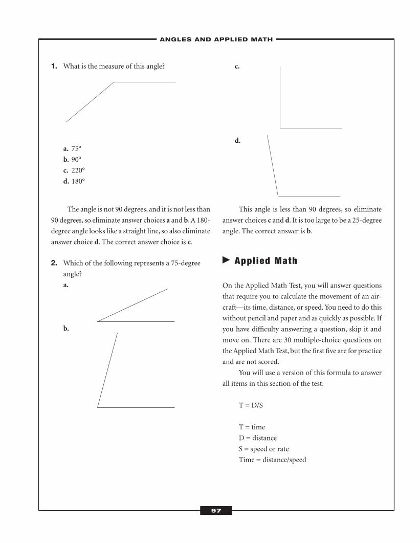
1. What is the measure of this angle?
a. 75°
b. 90°
c. 220°
d. 180°
The angle is not 90 degrees, and it is not less than
90 degrees, so eliminate answer choices a and b.A 180-
degree angle looks like a straight line, so also eliminate
answer choice d. The correct answer choice is c.
2. Which of the following represents a 75-degreeangle?
a.
b.
c.
d.
This angle is less than 90 degrees, so eliminate
answer choices c and d. It is too large to be a 25-degree
angle. The correct answer is b.
� Appl ied Math
On the Applied Math Test, you will answer questions
that require you to calculate the movement of an air-
craft—its time, distance, or speed. You need to do this
without pencil and paper and as quickly as possible. If
you have difficulty answering a question, skip it and
move on. There are 30 multiple-choice questions on
theAppliedMath Test, but the first five are for practice
and are not scored.
You will use a version of this formula to answer
all items in this section of the test:
T = D/S
T = time
D = distance
S = speed or rate
Time = distance/speed
–ANGLES AND APPLIED MATH–
97
ATC_2008b:Layout 1 11/24/08 1:15 PM Page 97
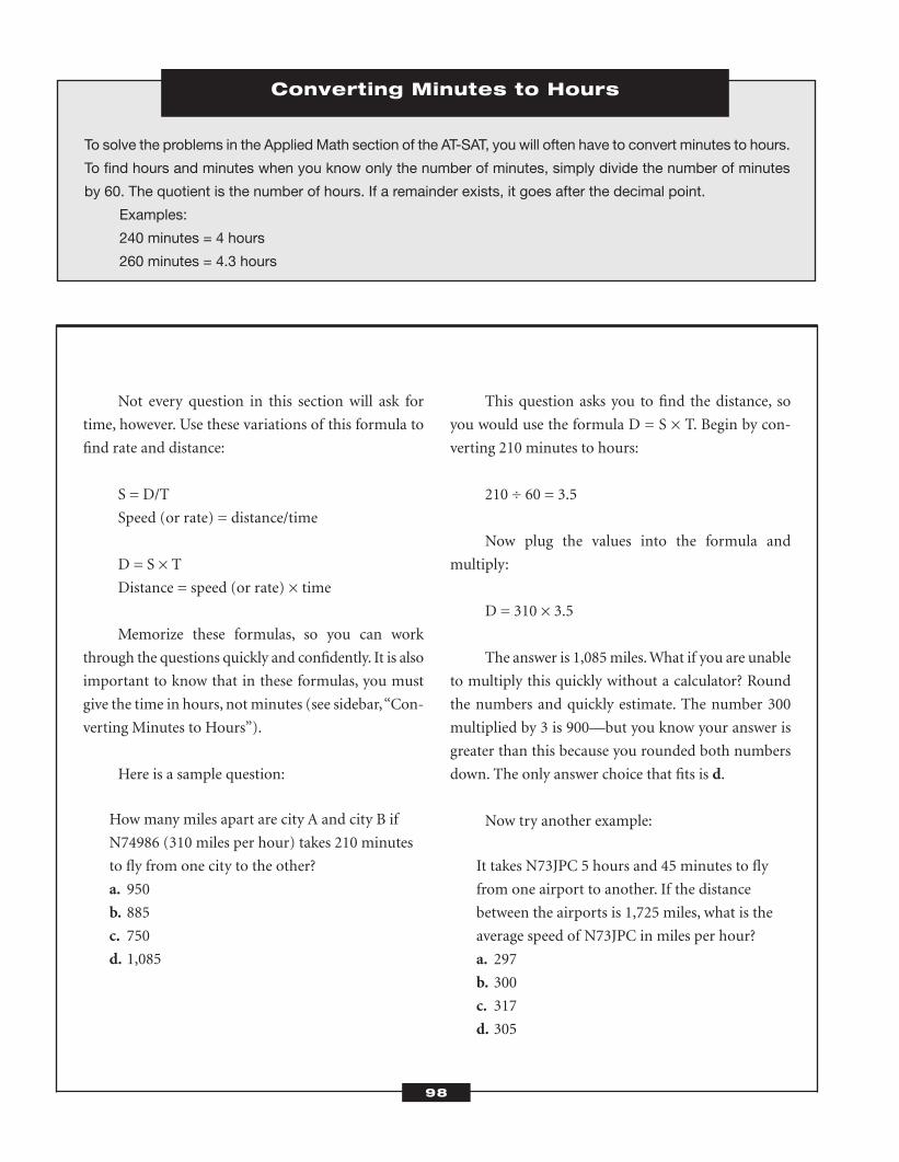
Not every question in this section will ask for
time, however. Use these variations of this formula to
find rate and distance:
S = D/T
Speed (or rate) = distance/time
D = S × T
Distance = speed (or rate) × time
Memorize these formulas, so you can work
through the questions quickly and confidently. It is also
important to know that in these formulas, you must
give the time in hours, not minutes (see sidebar,“Con-
verting Minutes to Hours”).
Here is a sample question:
How many miles apart are city A and city B if
N74986 (310 miles per hour) takes 210 minutes
to fly from one city to the other?
a. 950
b. 885
c. 750
d. 1,085
This question asks you to find the distance, so
you would use the formula D = S × T. Begin by con-
verting 210 minutes to hours:
210 ÷ 60 = 3.5
Now plug the values into the formula and
multiply:
D = 310 × 3.5
The answer is 1,085miles.What if you are unable
to multiply this quickly without a calculator? Round
the numbers and quickly estimate. The number 300
multiplied by 3 is 900—but you know your answer is
greater than this because you rounded both numbers
down. The only answer choice that fits is d.
Now try another example:
It takes N73JPC 5 hours and 45 minutes to fly
from one airport to another. If the distance
between the airports is 1,725 miles, what is the
average speed of N73JPC in miles per hour?
a. 297
b. 300
c. 317
d. 305
Converting Minutes to Hours
To solve the problems in the Applied Math section of the AT-SAT, you will often have to convert minutes to hours.
To find hours and minutes when you know only the number of minutes, simply divide the number of minutes
by 60. The quotient is the number of hours. If a remainder exists, it goes after the decimal point.
Examples:
240 minutes = 4 hours
260 minutes = 4.3 hours
98
ATC_2008b:Layout 1 11/24/08 1:15 PM Page 98
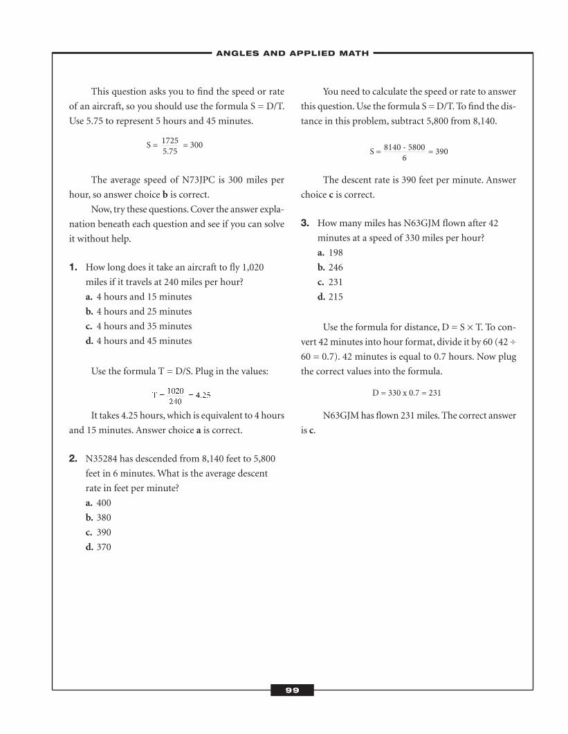
This question asks you to find the speed or rate
of an aircraft, so you should use the formula S = D/T.
Use 5.75 to represent 5 hours and 45 minutes.
The average speed of N73JPC is 300 miles per
hour, so answer choice b is correct.
Now, try these questions.Cover the answer expla-
nation beneath each question and see if you can solve
it without help.
1. How long does it take an aircraft to fly 1,020miles if it travels at 240 miles per hour?
a. 4 hours and 15 minutes
b. 4 hours and 25 minutes
c. 4 hours and 35 minutes
d. 4 hours and 45 minutes
Use the formula T = D/S. Plug in the values:
It takes 4.25 hours, which is equivalent to 4 hours
and 15 minutes. Answer choice a is correct.
2. N35284 has descended from 8,140 feet to 5,800feet in 6 minutes.What is the average descent
rate in feet per minute?
a. 400
b. 380
c. 390
d. 370
You need to calculate the speed or rate to answer
this question.Use the formula S =D/T. To find the dis-
tance in this problem, subtract 5,800 from 8,140.
The descent rate is 390 feet per minute. Answer
choice c is correct.
3. How many miles has N63GJM flown after 42
minutes at a speed of 330 miles per hour?
a. 198
b. 246
c. 231
d. 215
Use the formula for distance, D = S × T. To con-
vert 42minutes into hour format, divide it by 60 (42 ÷
60 = 0.7). 42 minutes is equal to 0.7 hours. Now plug
the correct values into the formula.
N63GJMhas flown 231miles. The correct answer
is c.
S = = 30017255.75
T = = 4.251020240
S = = 3908140 - 58006
D = 330 x 0.7 = 231
–ANGLES AND APPLIED MATH–
99
ATC_2008b:Layout 1 11/24/08 1:15 PM Page 99
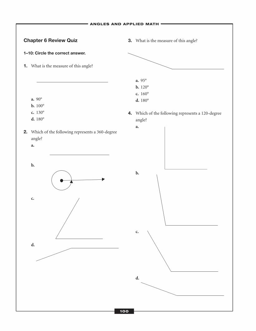
Chapter 6 Review Quiz
1–10: Circle the correct answer.
1. What is the measure of this angle?
a. 90°
b. 100°
c. 130°
d. 180°
2. Which of the following represents a 360-degreeangle?
a.
b.
c.
d.
3. What is the measure of this angle?
a. 95°
b. 120°
c. 160°
d. 180°
4. Which of the following represents a 120-degreeangle?
a.
b.
c.
d.
–ANGLES AND APPLIED MATH–
100
ATC_2008b:Layout 1 11/24/08 1:15 PM Page 100
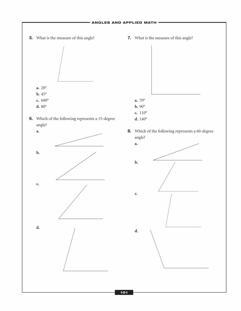
5. What is the measure of this angle?
a. 20°
b. 45°
c. 600°
d. 80°
6. Which of the following represents a 15-degreeangle?
a.
b.
c.
d.
7. What is the measure of this angle?
a. 70°
b. 90°
c. 110°
d. 140°
8. Which of the following represents a 60-degreeangle?
a.
b.
c.
d.
–ANGLES AND APPLIED MATH–
101
ATC_2008b:Layout 1 11/24/08 1:15 PM Page 101
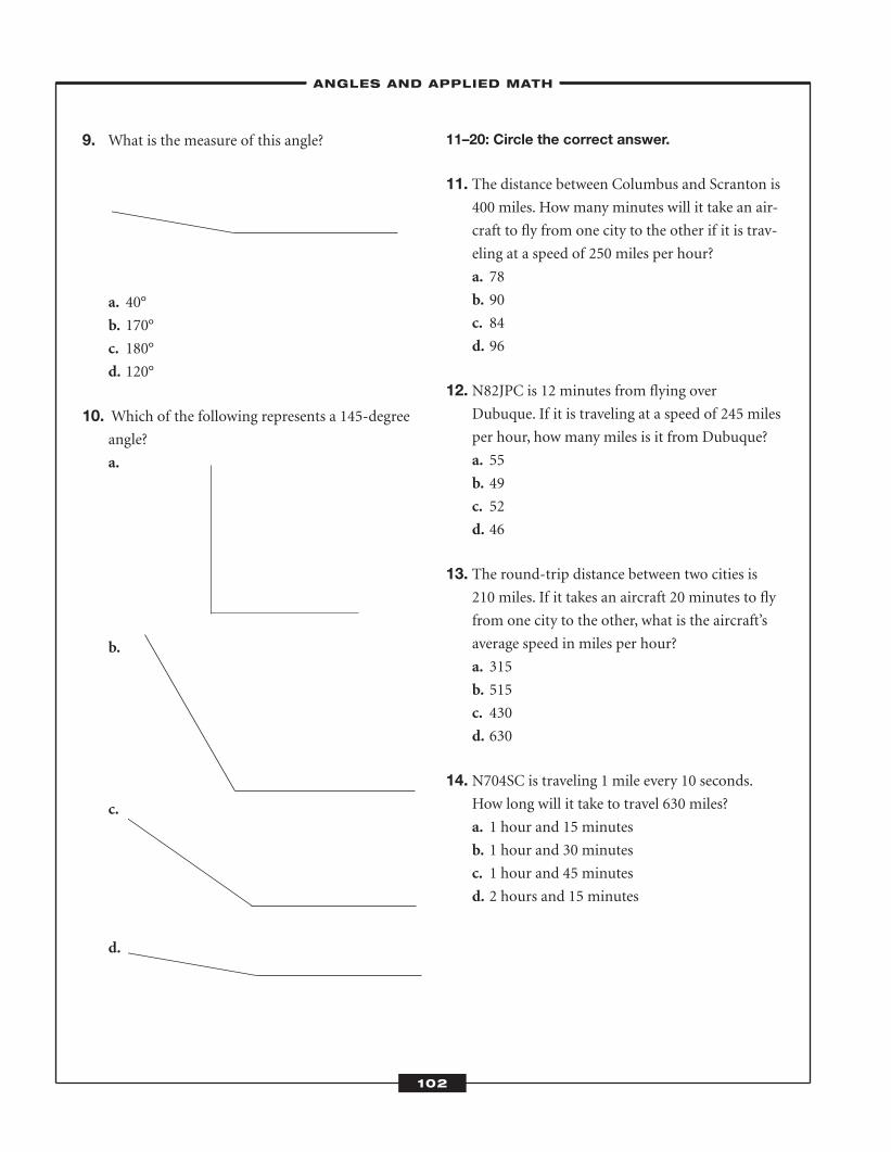
9. What is the measure of this angle?
a. 40°
b. 170°
c. 180°
d. 120°
10. Which of the following represents a 145-degreeangle?
a.
b.
c.
d.
11–20: Circle the correct answer.
11. The distance between Columbus and Scranton is400 miles. How many minutes will it take an air-
craft to fly from one city to the other if it is trav-
eling at a speed of 250 miles per hour?
a. 78
b. 90
c. 84
d. 96
12. N82JPC is 12 minutes from flying overDubuque. If it is traveling at a speed of 245 miles
per hour, how many miles is it from Dubuque?
a. 55
b. 49
c. 52
d. 46
13. The round-trip distance between two cities is210 miles. If it takes an aircraft 20 minutes to fly
from one city to the other, what is the aircraft’s
average speed in miles per hour?
a. 315
b. 515
c. 430
d. 630
14. N704SC is traveling 1 mile every 10 seconds.How long will it take to travel 630 miles?
a. 1 hour and 15 minutes
b. 1 hour and 30 minutes
c. 1 hour and 45 minutes
d. 2 hours and 15 minutes
–ANGLES AND APPLIED MATH–
102
ATC_2008b:Layout 1 11/24/08 1:15 PM Page 102
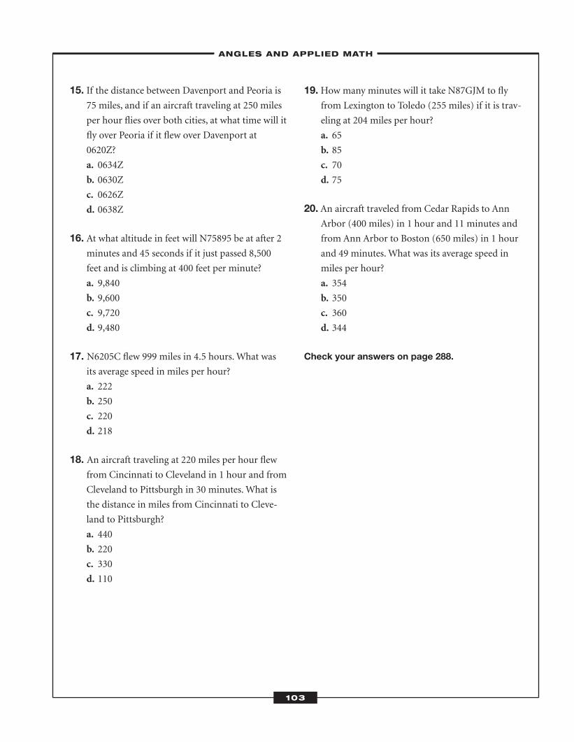
15. If the distance between Davenport and Peoria is75 miles, and if an aircraft traveling at 250 miles
per hour flies over both cities, at what time will it
fly over Peoria if it flew over Davenport at
0620Z?
a. 0634Z
b. 0630Z
c. 0626Z
d. 0638Z
16. At what altitude in feet will N75895 be at after 2minutes and 45 seconds if it just passed 8,500
feet and is climbing at 400 feet per minute?
a. 9,840
b. 9,600
c. 9,720
d. 9,480
17. N6205C flew 999 miles in 4.5 hours. What wasits average speed in miles per hour?
a. 222
b. 250
c. 220
d. 218
18. An aircraft traveling at 220 miles per hour flewfrom Cincinnati to Cleveland in 1 hour and from
Cleveland to Pittsburgh in 30 minutes. What is
the distance in miles from Cincinnati to Cleve-
land to Pittsburgh?
a. 440
b. 220
c. 330
d. 110
19.How many minutes will it take N87GJM to flyfrom Lexington to Toledo (255 miles) if it is trav-
eling at 204 miles per hour?
a. 65
b. 85
c. 70
d. 75
20. An aircraft traveled from Cedar Rapids to AnnArbor (400 miles) in 1 hour and 11 minutes and
from Ann Arbor to Boston (650 miles) in 1 hour
and 49 minutes. What was its average speed in
miles per hour?
a. 354
b. 350
c. 360
d. 344
Check your answers on page 288.
–ANGLES AND APPLIED MATH–
103
ATC_2008b:Layout 1 11/24/08 1:15 PM Page 103

ATC_2008b:Layout 1 11/24/08 1:15 PM Page 104
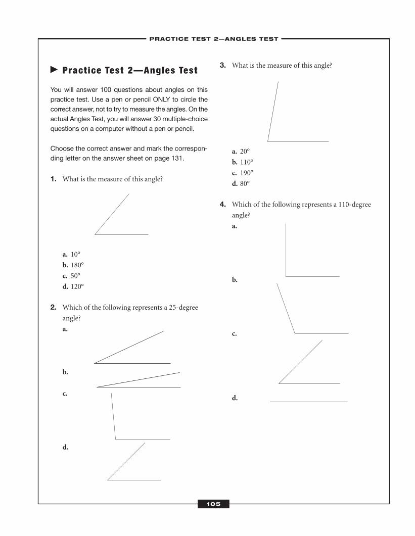
� Pract ice Test 2—Angles Test
You will answer 100 questions about angles on thispractice test. Use a pen or pencil ONLY to circle thecorrect answer, not to try to measure the angles. On theactual Angles Test, you will answer 30 multiple-choicequestions on a computer without a pen or pencil.
Choose the correct answer and mark the correspon-ding letter on the answer sheet on page 131.
1. What is the measure of this angle?
a. 10°
b. 180°
c. 50°
d. 120°
2. Which of the following represents a 25-degreeangle?
a.
b.
c.
d.
3. What is the measure of this angle?
a. 20°
b. 110°
c. 190°
d. 80°
4. Which of the following represents a 110-degreeangle?
a.
b.
c.
d.
–PRACTICE TEST 2—ANGLES TEST–
105
ATC_2008b:Layout 1 11/24/08 1:15 PM Page 105
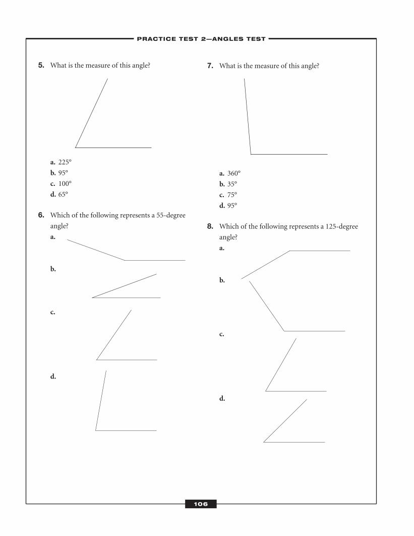
5. What is the measure of this angle?
a. 225°
b. 95°
c. 100°
d. 65°
6. Which of the following represents a 55-degreeangle?
a.
b.
c.
d.
7. What is the measure of this angle?
a. 360°
b. 35°
c. 75°
d. 95°
8. Which of the following represents a 125-degreeangle?
a.
b.
c.
d.
–PRACTICE TEST 2—ANGLES TEST–
106
ATC_2008b:Layout 1 11/24/08 1:15 PM Page 106
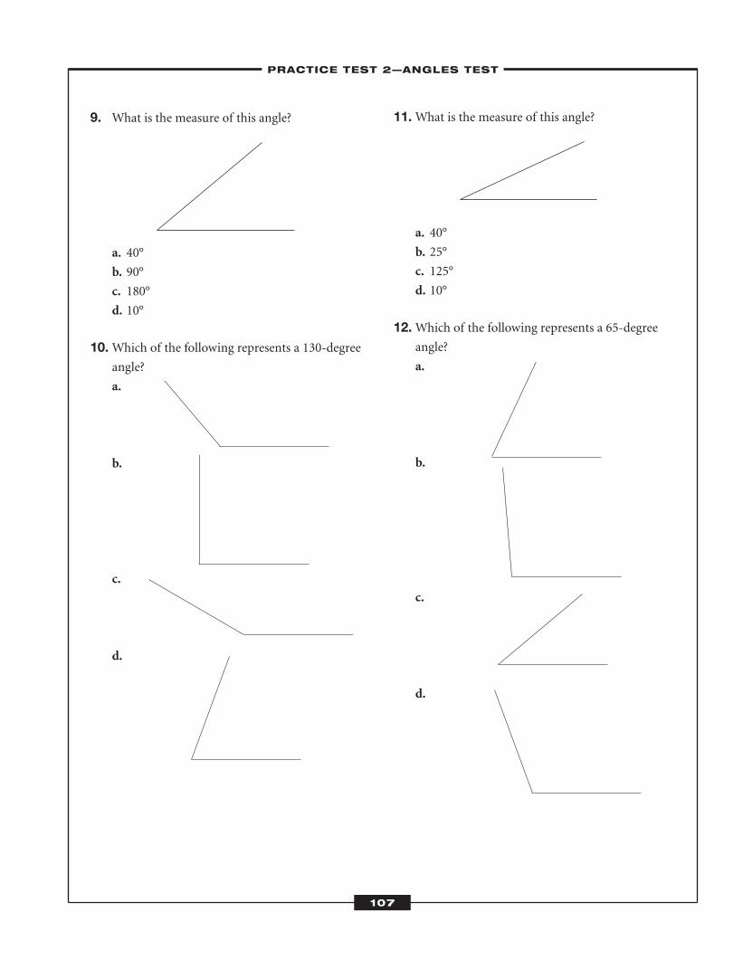
9. What is the measure of this angle?
a. 40°
b. 90°
c. 180°
d. 10°
10.Which of the following represents a 130-degreeangle?
a.
b.
c.
d.
11.What is the measure of this angle?
a. 40°
b. 25°
c. 125°
d. 10°
12.Which of the following represents a 65-degreeangle?
a.
b.
c.
d.
–PRACTICE TEST 2—ANGLES TEST–
107
ATC_2008b:Layout 1 11/24/08 1:15 PM Page 107
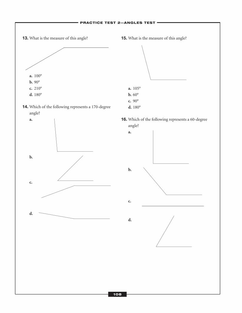
13.What is the measure of this angle?
a. 100°
b. 90°
c. 210°
d. 180°
14.Which of the following represents a 170-degreeangle?
a.
b.
c.
d.
15.What is the measure of this angle?
a. 105°
b. 60°
c. 90°
d. 180°
16.Which of the following represents a 60-degreeangle?
a.
b.
c.
d.
–PRACTICE TEST 2—ANGLES TEST–
108
ATC_2008b:Layout 1 11/24/08 1:15 PM Page 108
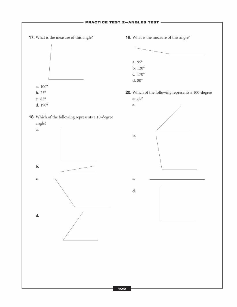
17.What is the measure of this angle?
a. 100°
b. 25°
c. 85°
d. 190°
18.Which of the following represents a 10-degreeangle?
a.
b.
c.
d.
19.What is the measure of this angle?
a. 95°
b. 120°
c. 170°
d. 80°
20.Which of the following represents a 100-degreeangle?
a.
b.
c.
d.
–PRACTICE TEST 2—ANGLES TEST–
109
ATC_2008b:Layout 1 11/24/08 1:15 PM Page 109
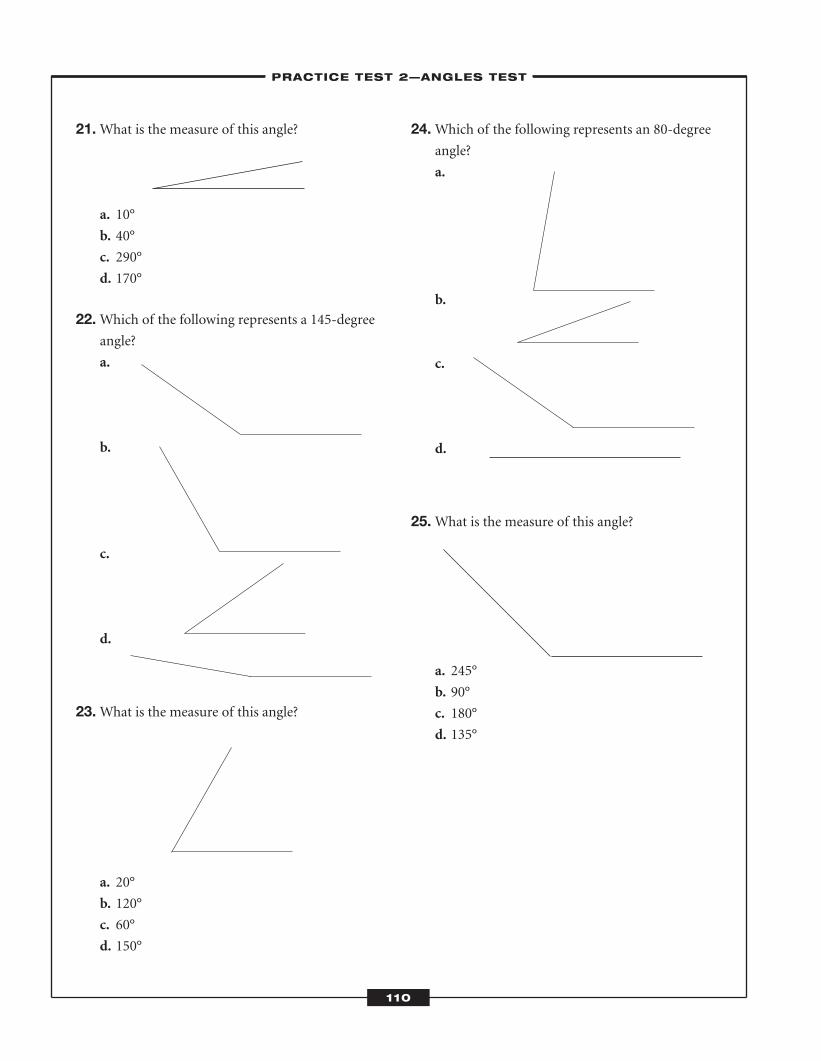
21.What is the measure of this angle?
a. 10°
b. 40°
c. 290°
d. 170°
22.Which of the following represents a 145-degreeangle?
a.
b.
c.
d.
23.What is the measure of this angle?
a. 20°
b. 120°
c. 60°
d. 150°
24.Which of the following represents an 80-degreeangle?
a.
b.
c.
d.
25.What is the measure of this angle?
a. 245°
b. 90°
c. 180°
d. 135°
–PRACTICE TEST 2—ANGLES TEST–
110
ATC_2008b:Layout 1 11/24/08 1:15 PM Page 110
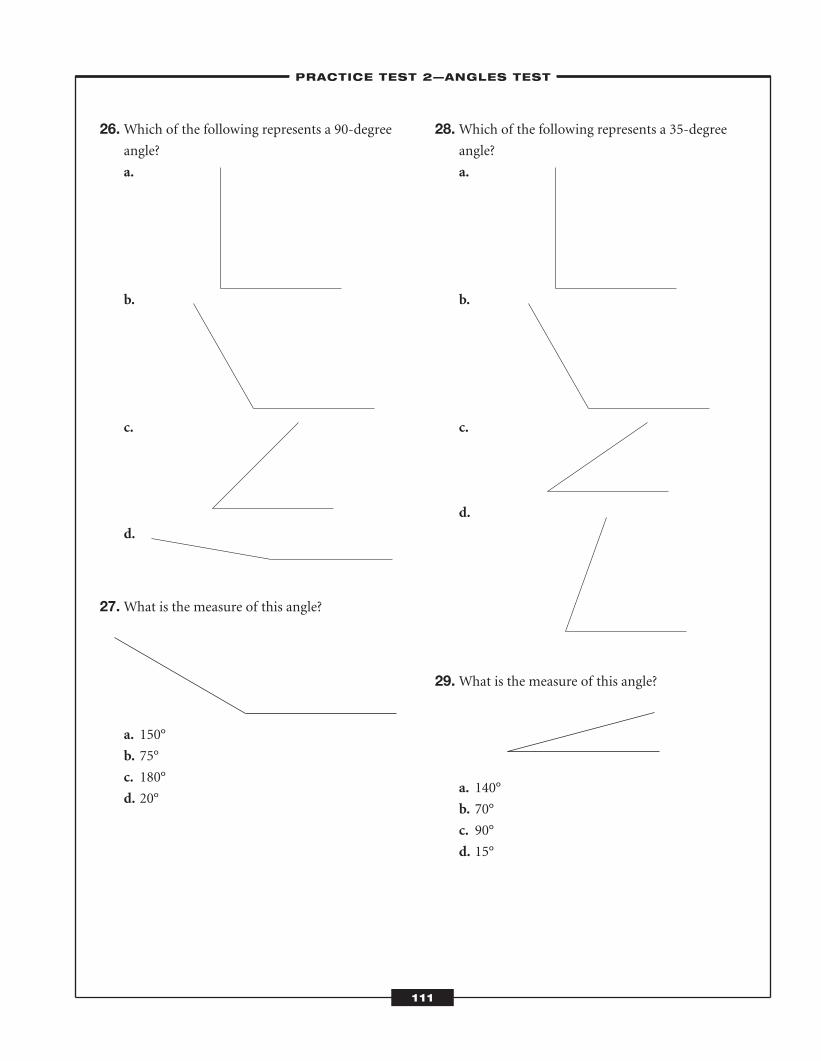
26.Which of the following represents a 90-degreeangle?
a.
b.
c.
d.
27.What is the measure of this angle?
a. 150°
b. 75°
c. 180°
d. 20°
28.Which of the following represents a 35-degreeangle?
a.
b.
c.
d.
29.What is the measure of this angle?
a. 140°
b. 70°
c. 90°
d. 15°
–PRACTICE TEST 2—ANGLES TEST–
111
ATC_2008b:Layout 1 11/24/08 1:15 PM Page 111
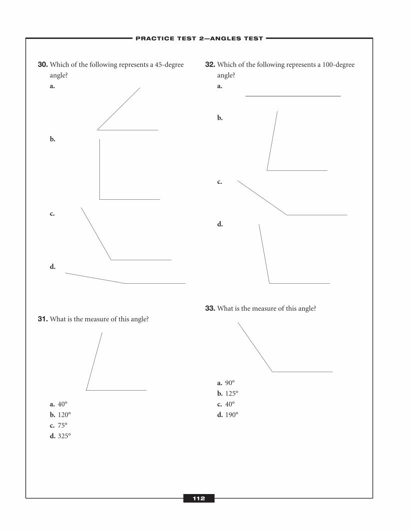
30.Which of the following represents a 45-degreeangle?
a.
b.
c.
d.
31.What is the measure of this angle?
a. 40°
b. 120°
c. 75°
d. 325°
32.Which of the following represents a 100-degreeangle?
a.
b.
c.
d.
33.What is the measure of this angle?
a. 90°
b. 125°
c. 40°
d. 190°
–PRACTICE TEST 2—ANGLES TEST–
112
ATC_2008b:Layout 1 11/24/08 1:15 PM Page 112
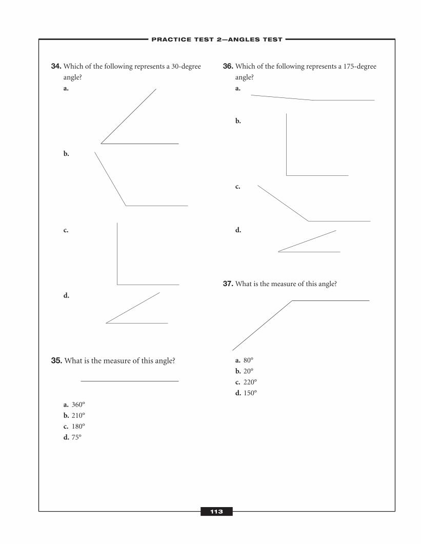
34.Which of the following represents a 30-degreeangle?
a.
b.
c.
d.
35. What is the measure of this angle?
a. 360°
b. 210°
c. 180°
d. 75°
36.Which of the following represents a 175-degreeangle?
a.
b.
c.
d.
37.What is the measure of this angle?
a. 80°
b. 20°
c. 220°
d. 150°
–PRACTICE TEST 2—ANGLES TEST–
113
ATC_2008b:Layout 1 11/24/08 1:15 PM Page 113
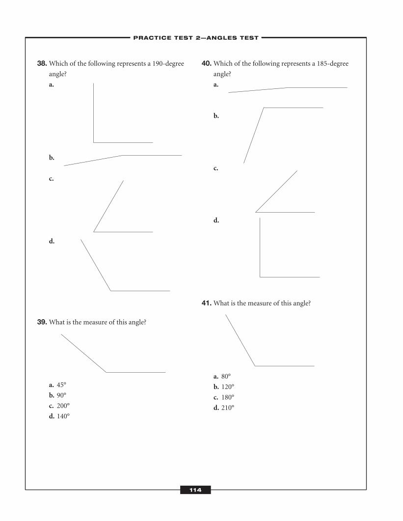
38.Which of the following represents a 190-degreeangle?
a.
b.
c.
d.
39.What is the measure of this angle?
a. 45°
b. 90°
c. 200°
d. 140°
40.Which of the following represents a 185-degreeangle?
a.
b.
c.
d.
41.What is the measure of this angle?
a. 80°
b. 120°
c. 180°
d. 210°
–PRACTICE TEST 2—ANGLES TEST–
114
ATC_2008b:Layout 1 11/24/08 1:15 PM Page 114
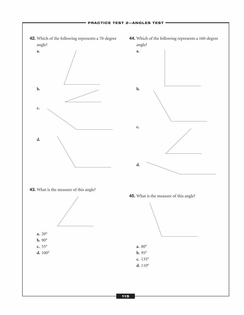
42.Which of the following represents a 70-degreeangle?
a.
b.
c.
d.
43.What is the measure of this angle?
a. 20°
b. 90°
c. 55°
d. 100°
44.Which of the following represents a 160-degreeangle?
a.
b.
c.
d.
45.What is the measure of this angle?
a. 80°
b. 95°
c. 135°
d. 110°
–PRACTICE TEST 2—ANGLES TEST–
115
ATC_2008b:Layout 1 11/24/08 1:15 PM Page 115
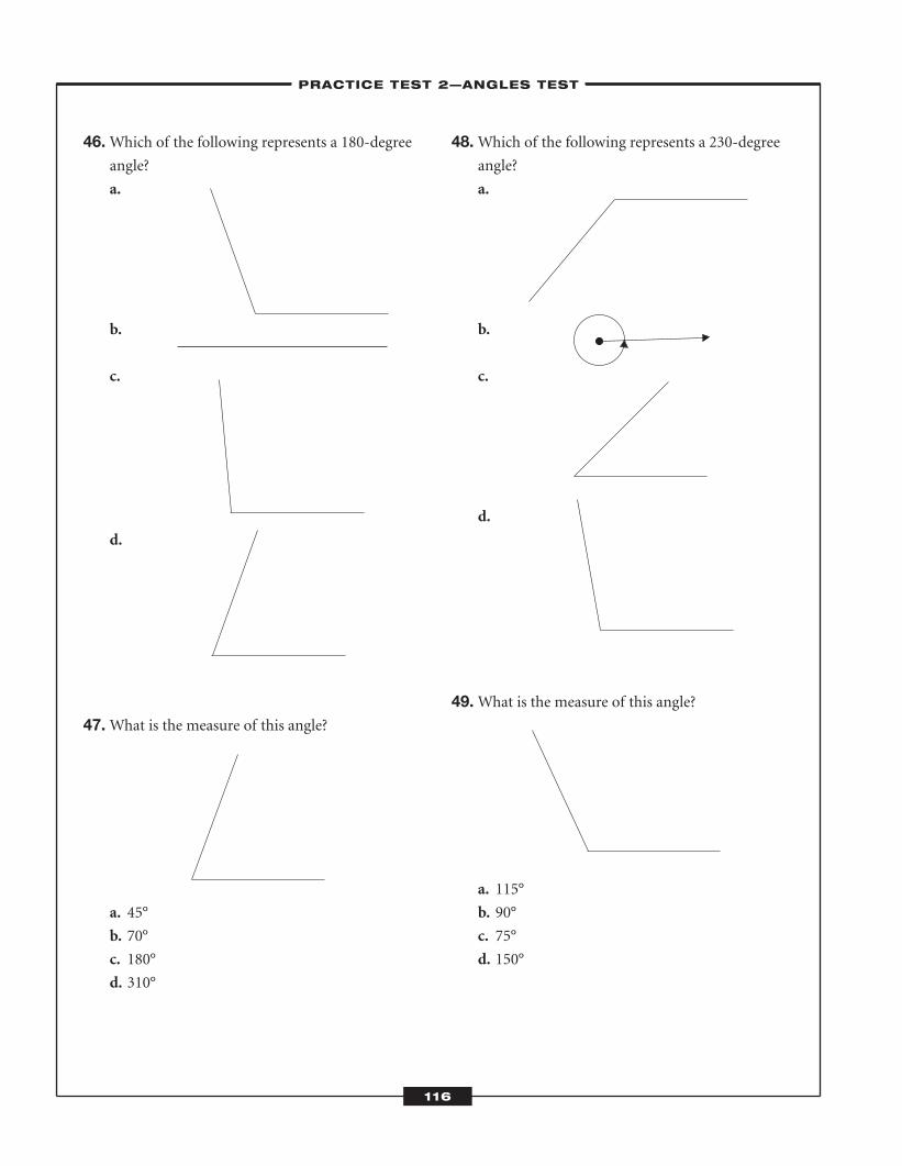
46.Which of the following represents a 180-degreeangle?
a.
b.
c.
d.
47.What is the measure of this angle?
a. 45°
b. 70°
c. 180°
d. 310°
48.Which of the following represents a 230-degreeangle?
a.
b.
c.
d.
49.What is the measure of this angle?
a. 115°
b. 90°
c. 75°
d. 150°
–PRACTICE TEST 2—ANGLES TEST–
116
ATC_2008b:Layout 1 11/24/08 1:16 PM Page 116
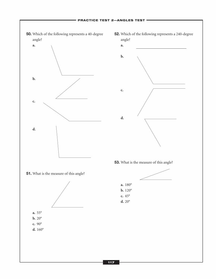
50.Which of the following represents a 40-degreeangle?
a.
b.
c.
d.
51.What is the measure of this angle?
a. 55°
b. 20°
c. 90°
d. 160°
52.Which of the following represents a 240-degreeangle?
a.
b.
c.
d.
53.What is the measure of this angle?
a. 180°
b. 120°
c. 45°
d. 20°
–PRACTICE TEST 2—ANGLES TEST–
117
ATC_2008b:Layout 1 11/24/08 1:16 PM Page 117
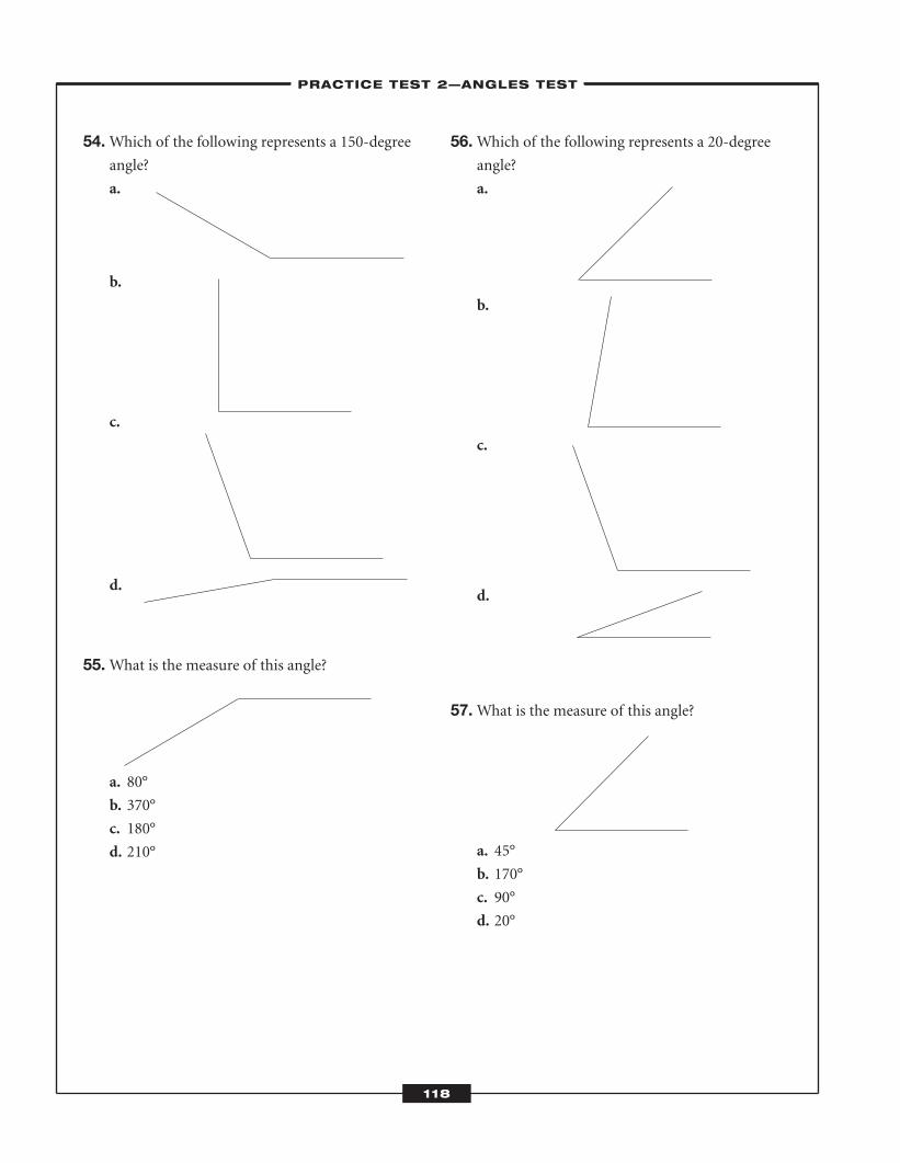
54.Which of the following represents a 150-degreeangle?
a.
b.
c.
d.
55.What is the measure of this angle?
a. 80°
b. 370°
c. 180°
d. 210°
56.Which of the following represents a 20-degreeangle?
a.
b.
c.
d.
57.What is the measure of this angle?
a. 45°
b. 170°
c. 90°
d. 20°
–PRACTICE TEST 2—ANGLES TEST–
118
ATC_2008b:Layout 1 11/24/08 1:16 PM Page 118
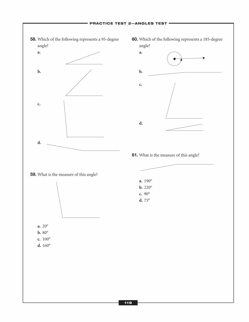
58.Which of the following represents a 95-degreeangle?
a.
b.
c.
d.
59.What is the measure of this angle?
a. 20°
b. 80°
c. 100°
d. 160°
60.Which of the following represents a 185-degreeangle?
a.
b.
c.
d.
61.What is the measure of this angle?
a. 190°
b. 220°
c. 90°
d. 75°
–PRACTICE TEST 2—ANGLES TEST–
119
ATC_2008b:Layout 1 11/24/08 1:16 PM Page 119
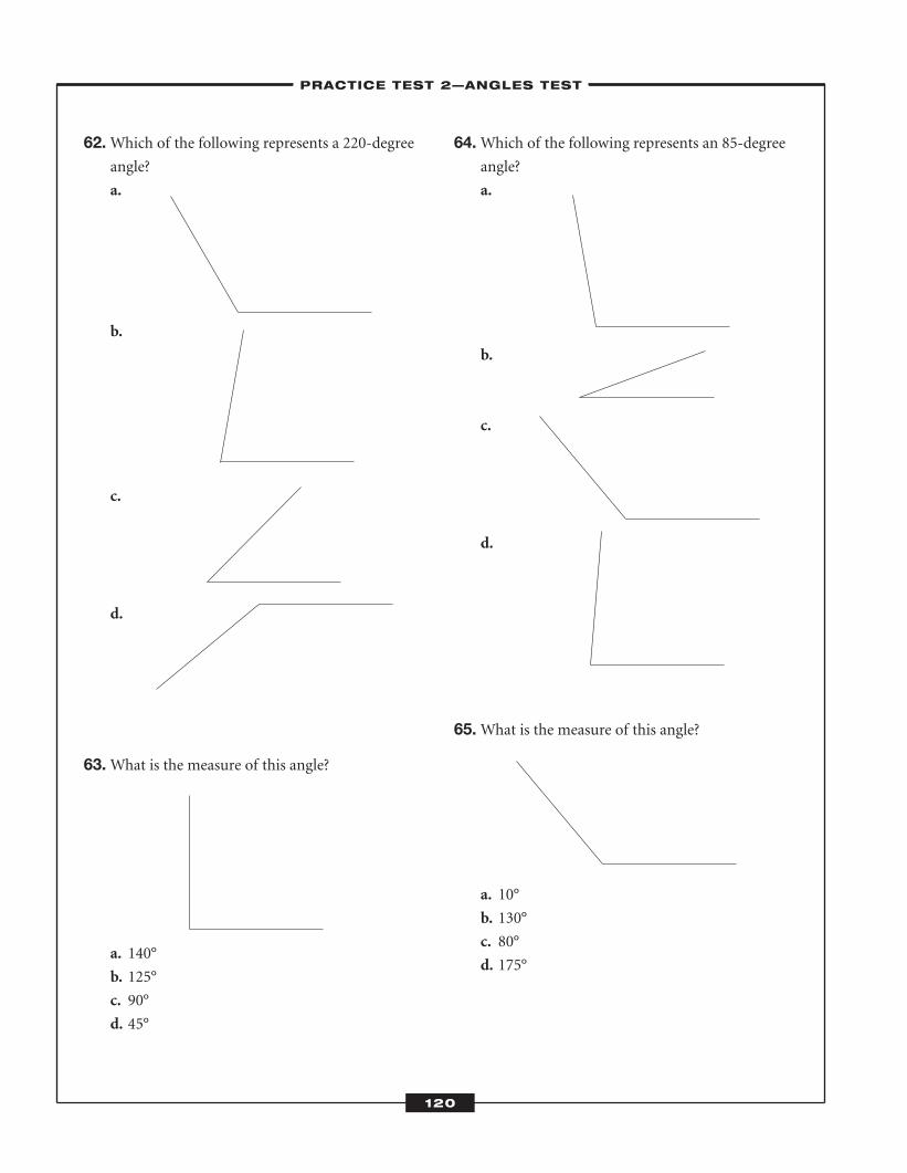
62.Which of the following represents a 220-degreeangle?
a.
b.
c.
d.
63.What is the measure of this angle?
a. 140°
b. 125°
c. 90°
d. 45°
64.Which of the following represents an 85-degreeangle?
a.
b.
c.
d.
65.What is the measure of this angle?
a. 10°
b. 130°
c. 80°
d. 175°
–PRACTICE TEST 2—ANGLES TEST–
120
ATC_2008b:Layout 1 11/24/08 1:16 PM Page 120
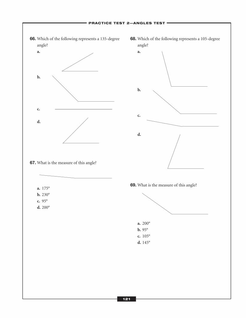
66.Which of the following represents a 135-degreeangle?
a.
b.
c.
d.
67.What is the measure of this angle?
a. 175°
b. 230°
c. 95°
d. 200°
68.Which of the following represents a 105-degreeangle?
a.
b.
c.
d.
69.What is the measure of this angle?
a. 200°
b. 95°
c. 105°
d. 145°
–PRACTICE TEST 2—ANGLES TEST–
121
ATC_2008b:Layout 1 11/24/08 1:16 PM Page 121
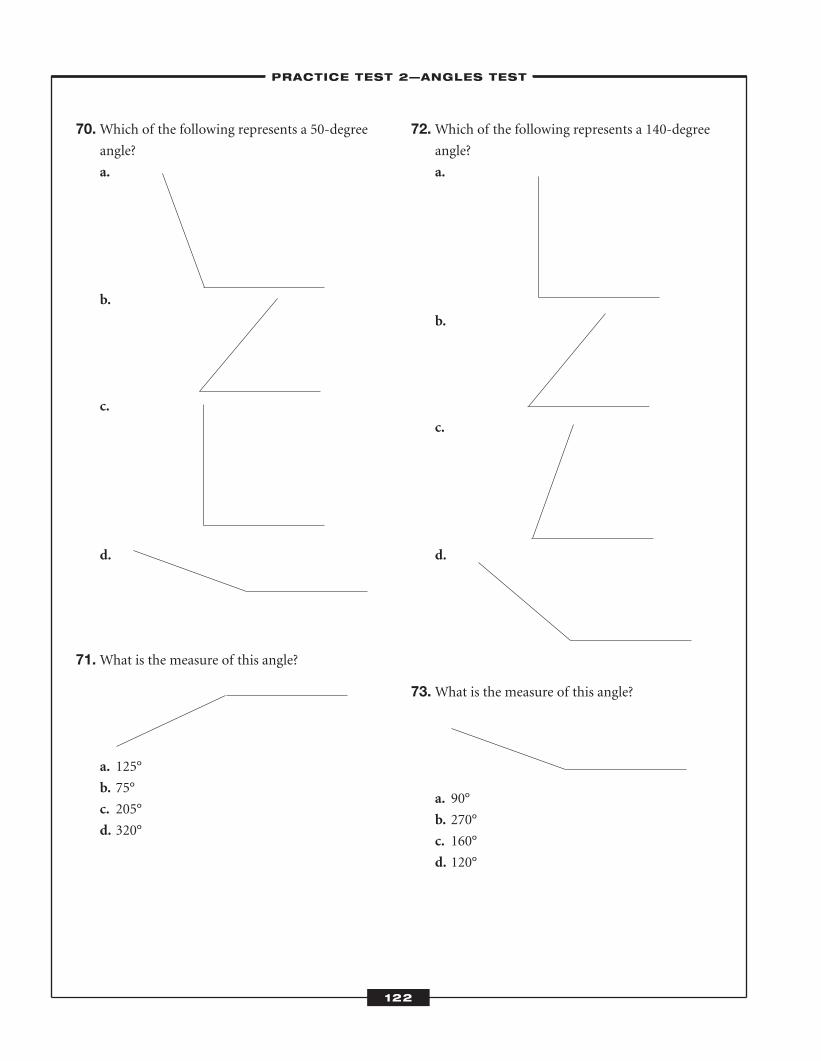
70.Which of the following represents a 50-degreeangle?
a.
b.
c.
d.
71.What is the measure of this angle?
a. 125°
b. 75°
c. 205°
d. 320°
72.Which of the following represents a 140-degreeangle?
a.
b.
c.
d.
73.What is the measure of this angle?
a. 90°
b. 270°
c. 160°
d. 120°
–PRACTICE TEST 2—ANGLES TEST–
122
ATC_2008b:Layout 1 11/24/08 1:16 PM Page 122
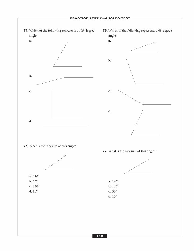
74.Which of the following represents a 195-degreeangle?
a.
b.
c.
d.
75.What is the measure of this angle?
a. 110°
b. 35°
c. 240°
d. 90°
76.Which of the following represents a 65-degreeangle?
a.
b.
c.
d.
77.What is the measure of this angle?
a. 140°
b. 120°
c. 30°
d. 10°
–PRACTICE TEST 2—ANGLES TEST–
123
ATC_2008b:Layout 1 11/24/08 1:16 PM Page 123
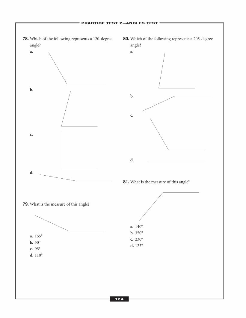
78.Which of the following represents a 120-degreeangle?
a.
b.
c.
d.
79.What is the measure of this angle?
a. 155°
b. 50°
c. 95°
d. 110°
80.Which of the following represents a 205-degreeangle?
a.
b.
c.
d.
81.What is the measure of this angle?
a. 140°
b. 350°
c. 230°
d. 125°
–PRACTICE TEST 2—ANGLES TEST–
124
ATC_2008b:Layout 1 11/24/08 1:16 PM Page 124
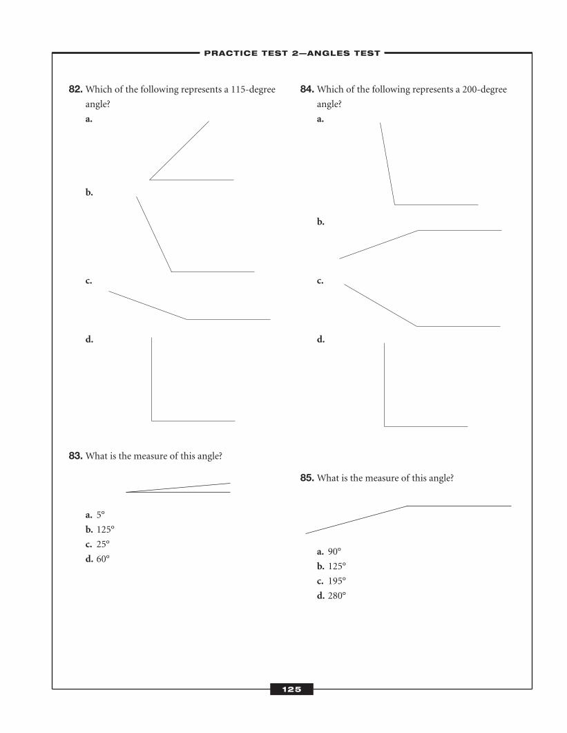
82.Which of the following represents a 115-degreeangle?
a.
b.
c.
d.
83.What is the measure of this angle?
a. 5°
b. 125°
c. 25°
d. 60°
84.Which of the following represents a 200-degreeangle?
a.
b.
c.
d.
85.What is the measure of this angle?
a. 90°
b. 125°
c. 195°
d. 280°
–PRACTICE TEST 2—ANGLES TEST–
125
ATC_2008b:Layout 1 11/24/08 1:16 PM Page 125
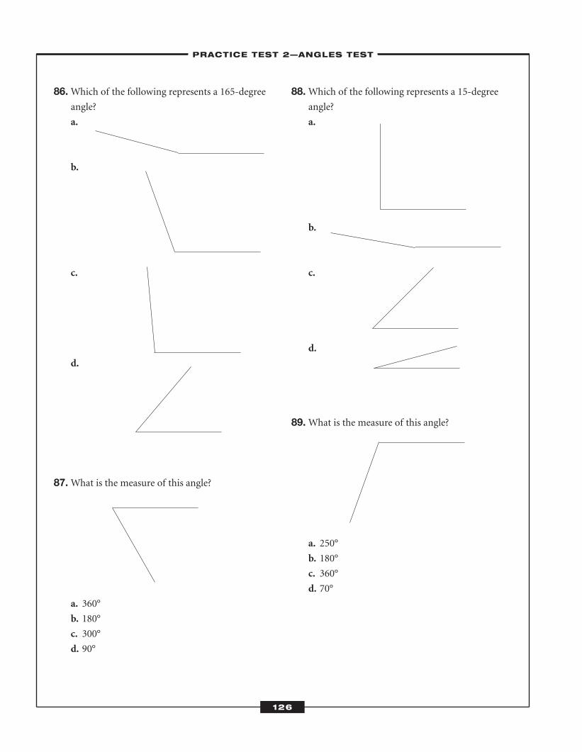
86.Which of the following represents a 165-degreeangle?
a.
b.
c.
d.
87.What is the measure of this angle?
a. 360°
b. 180°
c. 300°
d. 90°
88.Which of the following represents a 15-degreeangle?
a.
b.
c.
d.
89.What is the measure of this angle?
a. 250°
b. 180°
c. 360°
d. 70°
–PRACTICE TEST 2—ANGLES TEST–
126
ATC_2008b:Layout 1 11/24/08 1:16 PM Page 126
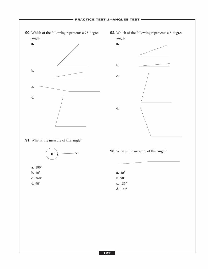
90.Which of the following represents a 75-degreeangle?
a.
b.
c.
d.
91.What is the measure of this angle?
a. 180°
b. 10°
c. 360°
d. 90°
92.Which of the following represents a 5-degreeangle?
a.
b.
c.
d.
93.What is the measure of this angle?
a. 30°
b. 90°
c. 185°
d. 120°
–PRACTICE TEST 2—ANGLES TEST–
127
ATC_2008b:Layout 1 11/24/08 1:16 PM Page 127
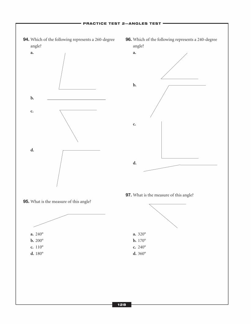
94.Which of the following represents a 260-degreeangle?
a.
b.
c.
d.
95.What is the measure of this angle?
a. 240°
b. 200°
c. 110°
d. 180°
96.Which of the following represents a 240-degreeangle?
a.
b.
c.
d.
97.What is the measure of this angle?
a. 320°
b. 170°
c. 240°
d. 360°
–PRACTICE TEST 2—ANGLES TEST–
128
ATC_2008b:Layout 1 11/24/08 1:16 PM Page 128
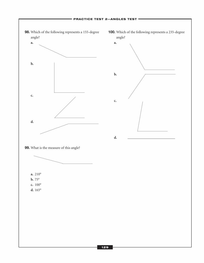
98.Which of the following represents a 155-degreeangle?
a.
b.
c.
d.
99.What is the measure of this angle?
a. 210°
b. 75°
c. 100°
d. 165°
100.Which of the following represents a 235-degreeangle?
a.
b.
c.
d.
–PRACTICE TEST 2—ANGLES TEST–
129
ATC_2008b:Layout 1 11/24/08 1:16 PM Page 129

ATC_2008b:Layout 1 11/24/08 1:16 PM Page 130

Practice Test 2—Angles Test
1. a b c d
2. a b c d
3. a b c d
4. a b c d
5. a b c d
6. a b c d
7. a b c d
8. a b c d
9. a b c d
10. a b c d
11. a b c d
12. a b c d
13. a b c d
14. a b c d
15. a b c d
16. a b c d
17. a b c d
18. a b c d
19. a b c d
20. a b c d
21. a b c d
22. a b c d
23. a b c d
24. a b c d
25. a b c d
26. a b c d
27. a b c d
28. a b c d
29. a b c d
30. a b c d
31. a b c d
32. a b c d
33. a b c d
34. a b c d
35. a b c d
36. a b c d
37. a b c d
38. a b c d
39. a b c d
40. a b c d
41. a b c d
42. a b c d
43. a b c d
44. a b c d
45. a b c d
46. a b c d
47. a b c d
48. a b c d
49. a b c d
50. a b c d
51. a b c d
52. a b c d
53. a b c d
54. a b c d
55. a b c d
56. a b c d
57. a b c d
58. a b c d
59. a b c d
60. a b c d
61. a b c d
62. a b c d
63. a b c d
64. a b c d
65. a b c d
66. a b c d
67. a b c d
68. a b c d
69. a b c d
70. a b c d
71. a b c d
72. a b c d
73. a b c d
74. a b c d
75. a b c d
76. a b c d
77. a b c d
78. a b c d
79. a b c d
80. a b c d
81. a b c d
82. a b c d
83. a b c d
84. a b c d
85. a b c d
86. a b c d
87. a b c d
88. a b c d
89. a b c d
90. a b c d
91. a b c d
92. a b c d
93. a b c d
94. a b c d
95. a b c d
96. a b c d
97. a b c d
98. a b c d
99. a b c d
100. a b c d
131
–LEARNINGEXPRESS ANSWER SHEET–
ATC_2008b:Layout 1 11/24/08 1:16 PM Page 131
� Answers and Explanat ions
1. c. This angle measures about 50 degrees. Theangle is an acute angle, so answer choices b
and d are not correct. An angle measuring 10
degrees is very small, so answer choice a is
not correct.
2. a. A 25-degree angle is a small angle, but not assmall as the angle in answer choice b, which is
about 10 degrees. The angles shown in
answer choices c and d are larger than 25
degrees.
3. d.This angle is an acute angle, which means itmeasures less than 90 degrees. The angle is
larger than a 20-degree angle, however.
4. b.A 100-degree angle is larger than 90 degreesand is an obtuse angle. You can therefore
eliminate answer choices a and c. A 180-
degree angle is a straight angle, which looks
like a straight line, so answer choice d is also
incorrect.
5. d.A 65-degree angle is less than 90 degrees andis an acute angle. The only angle that is acute
is the one shown in answer choice d.
6. c. A 55-degree angle is an acute angle, whichmeans its measure is less than 90 degrees.
Since answer choice a shows an obtuse angle,
it is not the correct answer. Answer choice d
shows an angle that is almost 90 degrees, so
this is not the correct answer. Answer choice
b shows an angle that is less than 55 degrees,
so this answer choice is not correct.
7. d.A 95-degree angle is an obtuse angle that isslightly larger than a 90-degree angle. Answer
choice d is correct.
8. b.An angle that is 125 degrees is obtuse, mean-ing its measure is more than 90 degrees. The
angles shown in answer choices c and d are
acute, so these answer choices are not correct.
The angle shown in answer choice a is much
larger than a 180-degree angle, which is a
straight angle, so this answer choice is not
correct.
9. a. A 40-degree angle is smaller than both a 90-degree angle and a 45-degree angle. Answer
choice a is correct.
10. a. A 130-degree angle is an obtuse angle that is50 degrees smaller than a 180-degree angle,
which is a straight angle. Answer choice a is
correct.
11. b.A 25-degree angle is small, but not as small asa 10-degree angle. Answer choice b is correct.
12. a. A 65-degree angle is larger than a 45-degreeangle, but not as large as a 95-degree angle. A
95-degree angle is shown in answer choice b,
so this answer choice is not correct. The angle
shown in answer choice d is obtuse, and the
angle shown in answer choice c is too small.
Answer choice a is correct.
13. c. This angle is a reflex angle, which means itsmeasure is greater than 180 degrees but not
more than 360 degrees. Answer choice c is
correct.
14. d.A 170-degree angle is almost a straight angle,which looks like a straight line. Answer choice
d is correct.
15. a. This angle is obtuse, which means its measureis greater than 90 degrees. Answer choice d is
a straight angle. Answer choice a is the cor-
rect answer; the angle shown is about 105
degrees.
16. d.A 60-degree angle is an acute angle, whichmeans its measure is less than 90 degrees. The
only answer choice showing an acute angle is
answer choice d.
–PRACTICE TEST 2—ANGLES TEST–
132
ATC_2008b:Layout 1 11/24/08 1:16 PM Page 132
17. c. An 85-degree angle looks almost like a rightangle, which is 90 degrees. Therefore, answer
choice c is correct.
18. b.A 10-degree angle is very small. Answerchoice b is correct.
19. c. A 180-degree angle is a straight angle. Thisangle is nearly straight, so it is about 170
degrees.
20. b.A 100-degree angle is slightly larger than a90-degree angle, which has perpendicular
rays. The angle shown in answer choice b is
about 100 degrees.
21. a. This angle is very small. It is only about 10degrees.
22. a. A 145-degree angle is an obtuse angle, whichmeans its measure is greater than 90 degrees.
A 180-degree angle is a straight angle, so a
145-degree angle has a measure between 90
and 180 degrees. The angle shown in answer
choice a is about 145 degrees.
23. c. This angle’s measure is less than 90 degreesbut greater than 20 degrees, so answer choice
a is not correct. Answer choices b and d show
obtuse angles, so these answer choices are
also not correct. Answer choice c is correct.
24. a. An 80-degree angle appears slightly smallerthan a right angle, which is 90 degrees. The
angle shown in answer choice a is about 80
degrees, so answer choice a is correct.
25. d.A 135-degree angle is an obtuse angle, whichmeans it is greater than 90 degrees. It is not as
large, however, as a 245- or 180-degree angle.
Answer choice d is correct.
26. a. The rays of a right angle are perpendicular.The angle in answer choice a is a 90-degree
angle, so answer choice a is correct.
27. a. The angle shown is about 150 degrees. Itsmeasure is greater than 90 degrees but less
than 180 degrees.
28. c. A 35-degree angle is a small angle that is lessthan 90 degrees. The angle in answer choice c
is about 35 degrees.
29. d.A 15-degree angle is very small. Answerchoices a, b, and c show angles larger than 15
degrees.
30. a. A 45-degree angle is half the size of a 90-degree angle. Answer choice a is a 45-degree
angle.
31. c. This angle is less than 90 degrees, but it is notas small as the angle shown in answer choice
a. The angle is about 75 degrees.
32. d.A 100-degree angle is slightly larger than aright angle. The angle shown in answer
choice d is about 100 degrees.
33. b.The angle shown is larger than a 90-degreeangle but much smaller than a 180-degree
angle. It is about 125 degrees.
34. d.A 30-degree angle is smaller than a 45-degreeangle, which is half the size of a 90-degree
angle. The angle shown in answer choice d is
30 degrees.
35. c. A straight angle looks like a straight line andis 180 degrees.
36. a. A 175-degree angle looks as if it is almost astraight line. Answer choice a is correct.
37. c. This angle is a reflex angle, which measuresmore than 180 degrees. This angle is about
220 degrees.
38. b.A 190-degree angle is slightly larger than a180-degree angle. Answer choice b shows a
190-degree angle.
39. d.This angle is obtuse, which means it is greaterthan 90 degrees, so answer choices a and b are
not correct. It is not as large as a 200-degree
angle, however, which is a reflex angle. It is
about 140 degrees.
40. a. A 185-degree angle is slightly larger than astraight angle. Answer choice a is correct.
–PRACTICE TEST 2—ANGLES TEST–
133
ATC_2008b:Layout 1 11/24/08 1:16 PM Page 133
41. b.The angle shown is about 120 degrees. It is anobtuse angle, an angle larger than 90 degrees,
but less than 180 degrees.
42. a. A 70-degree angle is an acute angle, whichmeans it measures less than 90 degrees. It is
larger than the angle shown in answer choice
b, however. The angle shown in answer choice
a is about 70 degrees.
43. c. The angle is acute, which means it is less than90 degrees. It is larger than a 20-degree angle,
however. The angle is about 55 degrees.
44. d.A 160-degree angle is an obtuse angle, whichmeans it measures more than 90 degrees but
less than 180 degrees. The angle in answer
choice b is only about 120 degrees, however.
45. d.The measure of this angle is slightly greaterthan 90 degrees; it is about 110 degrees.
46. b.A 180-degree angle is a straight angle. Answerchoice b is correct.
47. b.This angle is smaller than 90 degrees, but itsmeasure is greater than 45 degrees. It is about
70 degrees.
48. a. A 230-degree angle is a reflex angle, whichmeans it measures more than 180 degrees but
less than 360 degrees. The angle in answer
choice a is about 230 degrees.
49. a. This angle is obtuse, which means it is greaterthan 90 degrees. It is not as large as a 150-
degree angle, however. The angle is about 115
degrees.
50. b.A 40-degree angle is smaller than a 90-degreeangle. The only angle that is acute is the angle
in answer choice b.
51. a. This angle is less than 90 degrees, but itsmeasure is greater than 20 degrees. It is about
55 degrees.
52. c. A 240-degree angle is very large, but not aslarge as a 300-degree angle, which is shown in
answer choice d. The angle in answer choice c
is about 240 degrees.
53. d.This angle is very small, smaller than a 45-degree angle. It is about 20 degrees.
54. a. A 150-degree angle is larger than a 90-degreeangle, but its measure is less than 190 degrees.
The angle in answer choice a is about 150
degrees.
55. d.This angle is very large. Its measure is greaterthan 180 degrees. A 360-degree angle, how-
ever, is a circle. This angle is about 210
degrees.
56. d.A 20-degree angle is very small. The angle inanswer choice d is about 20 degrees.
57. a. A 45-degree angle is half the size of a 90-degree angle. Answer choice a is correct.
58. c. An angle that measures 95 degrees is slightlylarger than a 90-degree angle. The angle in
answer choice c is about 95 degrees.
59. c. A 100-degree angle is slightly larger than aright angle, which measures 90 degrees.
Answer choice c is correct.
60. b.A 185-degree angle is slightly larger than a180-degree angle, which looks like a straight
line. The angle in answer choice b is about
185 degrees.
61. a. A 190-degree angle has a measure that is 10degrees greater than a 180-degree angle,
which looks like a straight line. This angle is
about 190 degrees.
62. d.A 220-degree angle is a reflex angle that ismuch larger than the angle in answer choice
a, which is about 120 degrees. The angle in
answer choice d is about 220 degrees.
63. c. The angle shown has perpendicular rays. It isa right angle, which means it is 90 degrees.
64. d.An 85-degree angle is slightly smaller than a90-degree angle. The angle in answer choice d
is about 85 degrees.
–PRACTICE TEST 2—ANGLES TEST–
134
ATC_2008b:Layout 1 11/24/08 1:16 PM Page 134
65. b.The angle shown is obtuse, which means itmeasures more than 90 degrees. It does not
measure 175 degrees, however. It is a 130-
degree angle.
66. b.A 135-degree angle looks as if its measure isalmost halfway between 90 and 180 degrees.
The angle in answer choice b is about 135
degrees.
67. a. This angle looks as if it is nearly a straightline, which is 180 degrees. This angle is about
175 degrees.
68. a. A 105-degree angle is larger than a 90-degreeangle, but only by 15 degrees. The angle in
answer choice a is about 105 degrees.
69. d.This angle measures more than 90 degreesbut less than 180 degrees. It is about 145
degrees.
70. b.A 50-degree angle is less than 90 degrees. Theangle in answer choice b is about 50 degrees.
71. c. This angle is very large. It is greater than 180degrees. Its measure is less than 320 degrees,
however. It is a 205-degree angle.
72. d.A 140-degree angle has a measure greaterthan 90 degrees but less than 180 degrees.
The angle in answer choice d is about 140
degrees.
73. c. This angle measures more than 120 degreesbut less than 180 degrees. Its measure is about
160 degrees.
74. b.A 195-degree angle is larger than the angle inanswer choice d, which is about 180 degrees.
The angle in answer choice b is about 195
degrees.
75. b.This angle measures less than 90 degrees. Itmeasures about 35 degrees.
76. d.A 65-degree angle is smaller than a 90-degreeangle, but not as small as the angle in answer
choice a. The angle in answer choice d is
about 65 degrees.
77. c. This angle is very small, but its measure isgreater than 10 degrees. It is a 30-degree
angle.
78. a. A 120-degree angle is obtuse, which means itsmeasure is greater than 90 degrees. It is not as
large as the angle shown in answer choice d,
however, which has a measure of 170 degrees.
The angle in answer choice a is about 120
degrees.
79. a. This angle is greater than 90 degrees but lessthan 180 degrees—but its measure is closer to
180 degrees. The angle measures about 155
degrees.
80. b.A 205-degree angle is greater than a 180-degree angle, which is a straight angle. The
angle in answer choice b is about 205 degrees.
81. c. This angle measures more than 180 degrees,but the angle measures less than 350 degrees.
It is a 230-degree angle.
82. b.A 115-degree angle is an obtuse angle, whichmeans its measure is greater than 90 degrees.
Its measure is not as great as 160 degrees,
however. A 160-degree angle looks as if it is
nearly a straight line. The angle in answer
choice b is 115 degrees.
83. a. The measure of this angle is very small. It isonly about 5 degrees.
84. b.A 200-degree angle is a little larger than a180-degree angle, which looks like a straight
line. The angle in answer choice bmeasures
about 200 degrees.
85. c. This angle measures a little more than 180degrees. It is a 195-degree angle.
86. a. A 165-degree angle looks as if it is almost astraight line. The angle in answer choice a
measures 165 degrees.
87. c. This angle is not a complete angle, so answerchoice a is not correct. It is very large, how-
–PRACTICE TEST 2—ANGLES TEST–
135
ATC_2008b:Layout 1 11/24/08 1:16 PM Page 135
ever, much larger than 180 degrees. The angle
is about 300 degrees.
88. d.A 15-degree angle is very small. The angle inanswer choice dmeasures 15 degrees.
89. a. This is a very large angle, much larger than180 degrees. An angle that measures 360
degrees, however, is a complete angle, which
looks like a circle. The angle is about 250
degrees.
90. d.A 75-degree angle is slightly less than 90degrees. The angle in answer choice d is
about 75 degrees.
91. c. This angle is a complete angle, so its measureis 360 degrees.
92. b.A 5-degree angle is very small. The angle inanswer choice bmeasures about 5 degrees.
93. c. This angle is a little larger than a 180-degreeangle, which looks like a straight line. This
angle is about 185 degrees.
94. d.A 260-degree angle is very large, but not aslarge as a 300-degree angle, which looks like a
circle. The angle in answer choice d is about
260 degrees.
95. b.This angle looks a little larger than a 180-degree angle, which is a straight line. This
angle is about 200 degrees.
96. b.A 240-degree angle is very large, much largerthan a 180-degree angle. The angle in answer
choice b is 240 degrees.
97. a. This angle is not a complete circle, so answerchoice d is not correct. The angle is very
large, however. It is about 320 degrees.
98. a. A 155-degree angle is an obtuse angle, whichmeans it is larger than 90 degrees. It is smaller
than a 180-degree angle, which looks like a
straight line. The angle in answer choice a is
about 155 degrees.
99. d.This angle looks as if it is nearly a straightline. It is about 165 degrees.
100. b.An angle that measures 235 degrees is largerthan a 180-degree angle, which is in answer
choice d. The angle in answer choice b is
about 235 degrees.
–PRACTICE TEST 2—ANGLES TEST–
136
ATC_2008b:Layout 1 11/24/08 1:16 PM Page 136
� Pract ice Test 3—Applied MathTest
You will answer 100 applied math questions on thispractice test. Read and answer these questions asquickly as you can. If you are unsure of an answer,skip it and come back to it when you have finishedanswering the other questions. Memorize the formu-las in Chapter 6 before you take this test. Use yourpen or pencil ONLY to circle your answers. You willtake the actual test on a computer, and you will nothave a pencil and paper to calculate your answers.Perform the calculations in your head. The actualApplied Math Test contains 30 multiple-choice ques-tions, but the first five are not scored.
Choose the correct answer and mark the correspon-ding letter on the answer sheet on page 151.
This practice test can also be taken online. Turn to thescratch card in the back of this book for informationon accessing this practice test online with immediatescoring.
1. N83894 travels 28 miles every 8 minutes. Howmany miles does it travel in 5 hours and 36
minutes?
a. 1,196
b. 1,176
c. 1,156
d. 1,136
2. An aircraft traveling at 170 miles per hour flewover one airport at 0811Z and another airport at
1005Z. What is the distance between the two air-
ports in miles?
a. 319
b. 323
c. 327
d. 331
3. The distance from Flagstaff to Oklahoma City is800 miles. If N23GJM travels at 320 miles per
hour, how many hours will it take for it to make
the round trip between the two cities?
a. 2.5
b. 3
c. 5
d. 6
4. What is an aircraft’s average speed in miles perhour if it travels 984 miles in 288 minutes?
a. 195
b. 205
c. 215
d. 225
5. N89891 is at an altitude of 17,000 feet and isdescending at a rate of 420 feet per minute. What
will be its altitude in feet after 5 minutes and 6
seconds?
a. 14,816
b. 14,858
c. 14,900
d. 14,942
6. The distance between Las Vegas and Reno is 350miles. If N32692 leaves Las Vegas at 0757Z and
arrives in Reno at 0912Z, what is its average
speed in miles per hour?
a. 270
b. 285
c. 280
d. 290
–PRACTICE TEST 3—APPLIED MATH TEST–
137
ATC_2008b:Layout 1 11/24/08 1:16 PM Page 137
7. Two aircraft going in opposite directions passeach other at 0620Z. If one of the aircraft is trav-
eling at 190 miles per hour and the other aircraft
is traveling at 230 miles per hour, how many
miles will be between them at 0644Z?
a. 76
b. 92
c. 148
d. 168
8. N73961 has to make a 500-mile trip in less than1 hour and 42 minutes. How many miles per
hour minimum must it travel on average to
make this trip on time?
a. 293
b. 294
c. 295
d. 296
9. An aircraft took off in Eugene and landed inSeattle, 250 miles away. If, on average, it traveled
10 miles every 3 minutes, what time did it land
in Seattle if it took off from Eugene at 1033Z?
a. 1128Z
b. 1138Z
c. 1148Z
d. 1158Z
10. If an aircraft has been ascending at an averagerate of 900 feet per minute for the last 78 sec-
onds, how many feet has it ascended during that
time?
a. 1,160
b. 1,170
c. 1,180
d. 1,190
11. An aircraft has flown 525 miles in 105 minutes.What is the aircraft’s average ground speed in
knots?
a. 275
b. 300
c. 325
d. 350
12. Two aircraft are flying in the same direction. Oneaircraft passes the other at 0746Z. If one of the
aircraft is traveling at 205 miles per hour and the
other aircraft is traveling at 245 miles per hour,
what will be the distance between them in miles
at 0840Z?
a. 36
b. 34
c. 32
d. 30
13. How long would it take an aircraft traveling at190 miles per hour to make a round trip of 703
miles?
a. 3 hours and 30 minutes
b. 3 hours and 36 minutes
c. 3 hours and 42 minutes
d. 3 hours and 48 minutes
14. The distance between Indianapolis and Madisonis 270 miles. If N22371 took off from Indianapo-
lis and is halfway to Madison, how long has it
been traveling if it is flying at 200 miles per
hour?
a. 38 minutes and 30 seconds
b. 39 minutes and 30 seconds
c. 40 minutes and 30 seconds
d. 42 minutes and 30 seconds
–PRACTICE TEST 3—APPLIED MATH TEST–
138
ATC_2008b:Layout 1 11/24/08 1:16 PM Page 138
15. N44770 traveled 231 miles in 66 minutes,N13121 traveled 220 miles in 1 hour, N79928
traveled 152 miles in 48 minutes, and N81276
traveled 115 miles in 30 minutes. Which aircraft
had the highest average speed?
a. N13121
b. N44770
c. N79928
d. N81276
16. If an aircraft travels at 170 miles per hour, howmany miles does it travel in 21 minutes?
a. 58
b. 59.5
c. 60
d. 61.5
17. N65969 flew from Tucson to Phoenix in 33 min-utes, while N44439 made the same trip in 40
minutes. If the distance between Tucson and
Phoenix is 110 miles, how many miles per hour
faster on average did N65969 travel than
N44439?
a. 33
b. 35
c. 39
d. 37
18. An aircraft traveled the first 80 miles of a 320-mile flight in 20 minutes, and it traveled the
remainder of the flight in 1 hour. What was the
average speed of the aircraft in miles per hour?
a. 230
b. 240
c. 250
d. 260
19. An aircraft is descending 1,275 feet every 3 sec-onds. How many feet will it descend in 8
seconds?
a. 3,400
b. 3,475
c. 3,500
d. 3,575
20. N59423 is traveling at 160 miles per hour andflew over Flint 45 minutes ago. How many miles
outside Flint is the aircraft?
a. 100
b. 120
c. 140
d. 160
21. An aircraft made the 120-mile trip from TampaBay to Gainesville, flying at 250 miles per hour.
How long did the trip take?
a. 28 minutes and 42 seconds
b. 28 minutes and 48 seconds
c. 28 minutes and 54 seconds
d. 29 minutes and 6 seconds
22. N52GJM took off from El Paso 2 hours and 6minutes ago and has been traveling at an average
speed of 260 miles per hour. If it flew over ABC
airport 18 minutes ago, how many miles is it
from El Paso to ABC airport?
a. 468
b. 520
c. 598
d. 572
–PRACTICE TEST 3—APPLIED MATH TEST–
139
ATC_2008b:Layout 1 11/24/08 1:16 PM Page 139
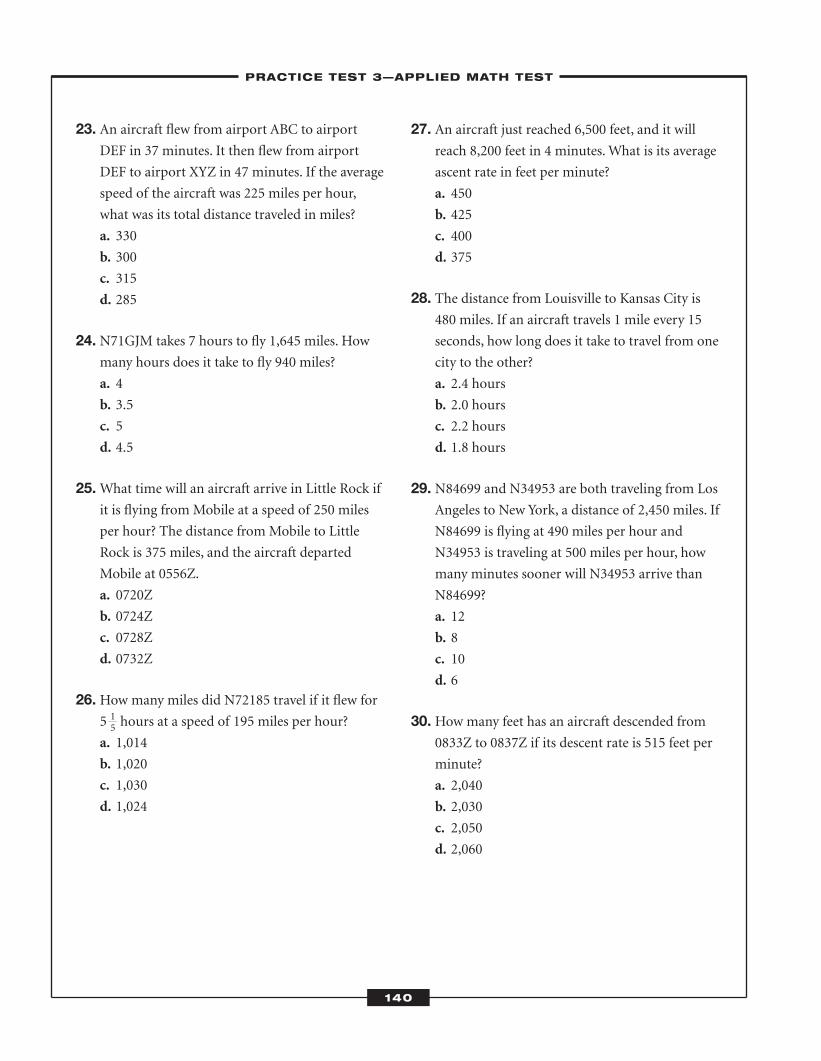
23. An aircraft flew from airport ABC to airportDEF in 37 minutes. It then flew from airport
DEF to airport XYZ in 47 minutes. If the average
speed of the aircraft was 225 miles per hour,
what was its total distance traveled in miles?
a. 330
b. 300
c. 315
d. 285
24. N71GJM takes 7 hours to fly 1,645 miles. Howmany hours does it take to fly 940 miles?
a. 4
b. 3.5
c. 5
d. 4.5
25.What time will an aircraft arrive in Little Rock ifit is flying from Mobile at a speed of 250 miles
per hour? The distance from Mobile to Little
Rock is 375 miles, and the aircraft departed
Mobile at 0556Z.
a. 0720Z
b. 0724Z
c. 0728Z
d. 0732Z
26. How many miles did N72185 travel if it flew for5 hours at a speed of 195 miles per hour?
a. 1,014
b. 1,020
c. 1,030
d. 1,024
27. An aircraft just reached 6,500 feet, and it willreach 8,200 feet in 4 minutes. What is its average
ascent rate in feet per minute?
a. 450
b. 425
c. 400
d. 375
28. The distance from Louisville to Kansas City is480 miles. If an aircraft travels 1 mile every 15
seconds, how long does it take to travel from one
city to the other?
a. 2.4 hours
b. 2.0 hours
c. 2.2 hours
d. 1.8 hours
29. N84699 and N34953 are both traveling from LosAngeles to New York, a distance of 2,450 miles. If
N84699 is flying at 490 miles per hour and
N34953 is traveling at 500 miles per hour, how
many minutes sooner will N34953 arrive than
N84699?
a. 12
b. 8
c. 10
d. 6
30. How many feet has an aircraft descended from0833Z to 0837Z if its descent rate is 515 feet per
minute?
a. 2,040
b. 2,030
c. 2,050
d. 2,060
–PRACTICE TEST 3—APPLIED MATH TEST–
140
15
ATC_2008b:Layout 1 11/24/08 1:16 PM Page 140
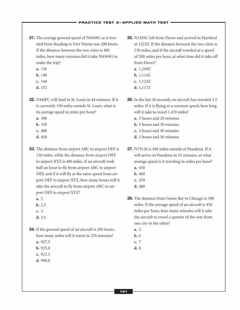
31. The average ground speed of N4569G as it trav-eled from Reading to Fort Wayne was 200 knots.
If the distance between the two cities is 480
miles, how many minutes did it take N4569G to
make the trip?
a. 136
b. 140
c. 144
d. 152
32. N44JPC will land in St. Louis in 44 minutes. If itis currently 330 miles outside St. Louis, what is
its average speed in miles per hour?
a. 300
b. 350
c. 400
d. 450
33. The distance from airport ABC to airport DEF is120 miles, while the distance from airport DEF
to airport XYZ is 480 miles. If an aircraft took
half an hour to fly from airport ABC to airport
DEF, and if it will fly at the same speed from air-
port DEF to airport XYZ, how many hours will it
take the aircraft to fly from airport ABC to air-
port DEF to airport XYZ?
a. 2
b. 2.5
c. 3
d. 3.5
34. If the ground speed of an aircraft is 205 knots,how many miles will it travel in 270 minutes?
a. 927.5
b. 925.0
c. 922.5
d. 900.0
35. N3285C left from Dover and arrived in Hartfordat 1223Z. If the distance between the two cities is
230 miles, and if the aircraft traveled at a speed
of 200 miles per hour, at what time did it take off
from Dover?
a. 1,109Z
b. 1,114Z
c. 1,123Z
d. 1,117Z
36. In the last 30 seconds, an aircraft has traveled 3.5miles. If it is flying at a constant speed, how long
will it take to travel 1,470 miles?
a. 3 hours and 20 minutes
b. 3 hours and 30 minutes
c. 3 hours and 40 minutes
d. 3 hours and 50 minutes
37. N79126 is 440 miles outside of Pasadena. If itwill arrive in Pasadena in 55 minutes, at what
average speed is it traveling in miles per hour?
a. 450
b. 460
c. 470
d. 480
38. The distance from Green Bay to Chicago is 180miles. If the average speed of an aircraft is 450
miles per hour, how many minutes will it take
the aircraft to travel a quarter of the way from
one city to the other?
a. 5
b. 6
c. 7
d. 8
–PRACTICE TEST 3—APPLIED MATH TEST–
141
ATC_2008b:Layout 1 11/24/08 1:16 PM Page 141
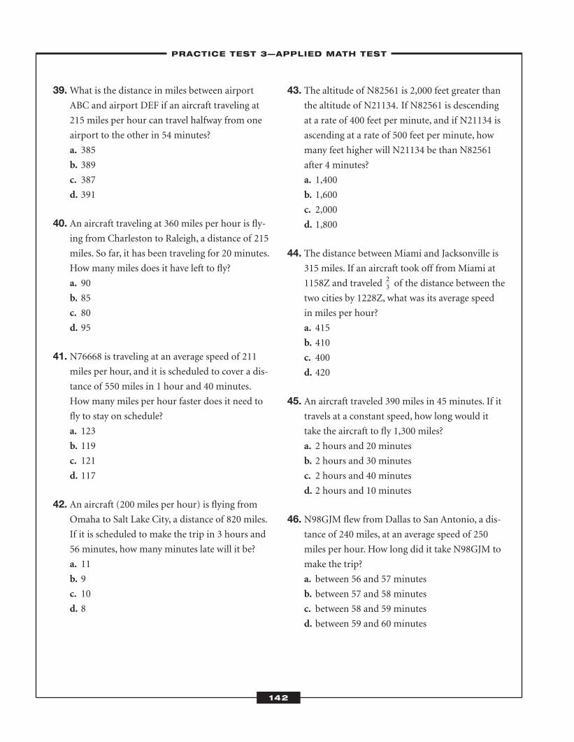
39.What is the distance in miles between airportABC and airport DEF if an aircraft traveling at
215 miles per hour can travel halfway from one
airport to the other in 54 minutes?
a. 385
b. 389
c. 387
d. 391
40. An aircraft traveling at 360 miles per hour is fly-ing from Charleston to Raleigh, a distance of 215
miles. So far, it has been traveling for 20 minutes.
How many miles does it have left to fly?
a. 90
b. 85
c. 80
d. 95
41. N76668 is traveling at an average speed of 211miles per hour, and it is scheduled to cover a dis-
tance of 550 miles in 1 hour and 40 minutes.
How many miles per hour faster does it need to
fly to stay on schedule?
a. 123
b. 119
c. 121
d. 117
42. An aircraft (200 miles per hour) is flying fromOmaha to Salt Lake City, a distance of 820 miles.
If it is scheduled to make the trip in 3 hours and
56 minutes, how many minutes late will it be?
a. 11
b. 9
c. 10
d. 8
43. The altitude of N82561 is 2,000 feet greater thanthe altitude of N21134. If N82561 is descending
at a rate of 400 feet per minute, and if N21134 is
ascending at a rate of 500 feet per minute, how
many feet higher will N21134 be than N82561
after 4 minutes?
a. 1,400
b. 1,600
c. 2,000
d. 1,800
44. The distance between Miami and Jacksonville is315 miles. If an aircraft took off from Miami at
1158Z and traveled of the distance between the
two cities by 1228Z, what was its average speed
in miles per hour?
a. 415
b. 410
c. 400
d. 420
45. An aircraft traveled 390 miles in 45 minutes. If ittravels at a constant speed, how long would it
take the aircraft to fly 1,300 miles?
a. 2 hours and 20 minutes
b. 2 hours and 30 minutes
c. 2 hours and 40 minutes
d. 2 hours and 10 minutes
46. N98GJM flew from Dallas to San Antonio, a dis-tance of 240 miles, at an average speed of 250
miles per hour. How long did it take N98GJM to
make the trip?
a. between 56 and 57 minutes
b. between 57 and 58 minutes
c. between 58 and 59 minutes
d. between 59 and 60 minutes
–PRACTICE TEST 3—APPLIED MATH TEST–
142
23
ATC_2008b:Layout 1 11/24/08 1:16 PM Page 142
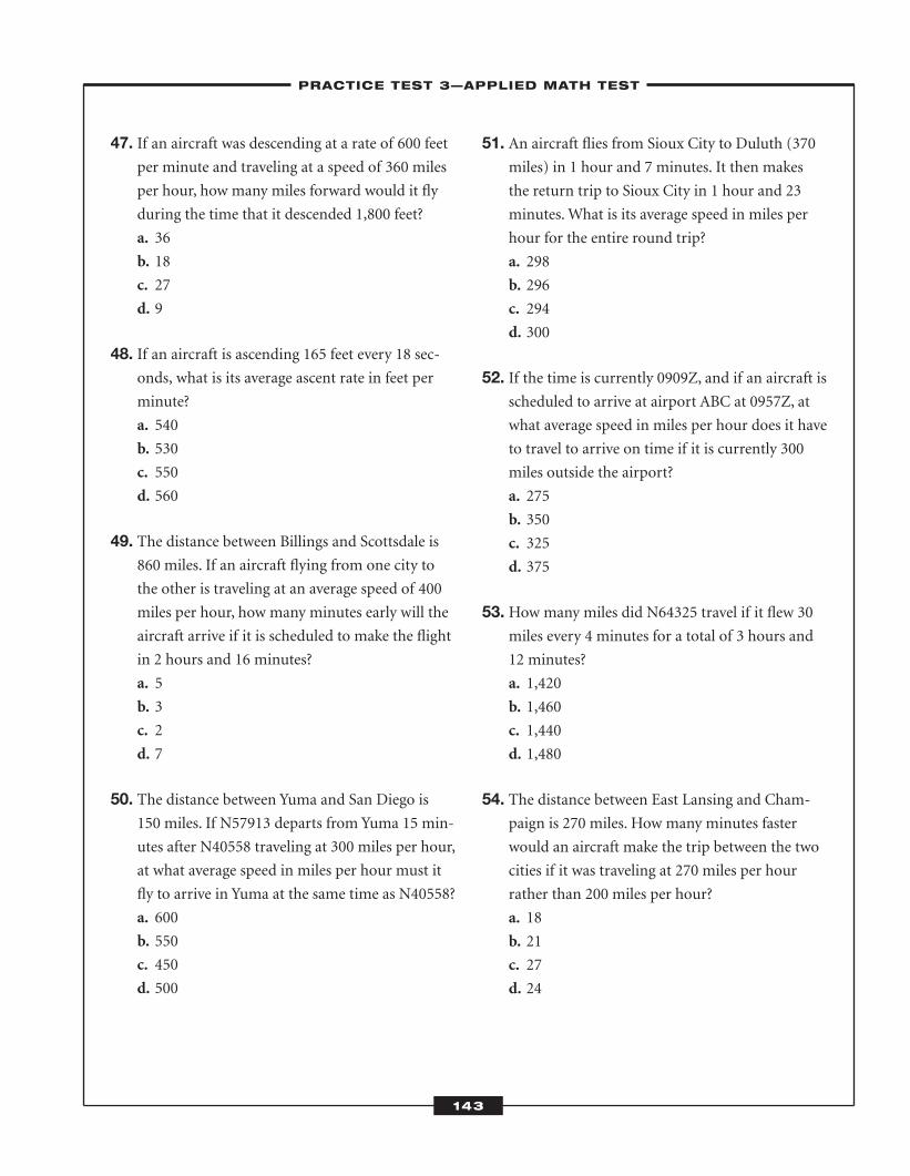
47. If an aircraft was descending at a rate of 600 feetper minute and traveling at a speed of 360 miles
per hour, how many miles forward would it fly
during the time that it descended 1,800 feet?
a. 36
b. 18
c. 27
d. 9
48. If an aircraft is ascending 165 feet every 18 sec-onds, what is its average ascent rate in feet per
minute?
a. 540
b. 530
c. 550
d. 560
49. The distance between Billings and Scottsdale is860 miles. If an aircraft flying from one city to
the other is traveling at an average speed of 400
miles per hour, how many minutes early will the
aircraft arrive if it is scheduled to make the flight
in 2 hours and 16 minutes?
a. 5
b. 3
c. 2
d. 7
50. The distance between Yuma and San Diego is150 miles. If N57913 departs from Yuma 15 min-
utes after N40558 traveling at 300 miles per hour,
at what average speed in miles per hour must it
fly to arrive in Yuma at the same time as N40558?
a. 600
b. 550
c. 450
d. 500
51. An aircraft flies from Sioux City to Duluth (370miles) in 1 hour and 7 minutes. It then makes
the return trip to Sioux City in 1 hour and 23
minutes. What is its average speed in miles per
hour for the entire round trip?
a. 298
b. 296
c. 294
d. 300
52. If the time is currently 0909Z, and if an aircraft isscheduled to arrive at airport ABC at 0957Z, at
what average speed in miles per hour does it have
to travel to arrive on time if it is currently 300
miles outside the airport?
a. 275
b. 350
c. 325
d. 375
53. How many miles did N64325 travel if it flew 30miles every 4 minutes for a total of 3 hours and
12 minutes?
a. 1,420
b. 1,460
c. 1,440
d. 1,480
54. The distance between East Lansing and Cham-paign is 270 miles. How many minutes faster
would an aircraft make the trip between the two
cities if it was traveling at 270 miles per hour
rather than 200 miles per hour?
a. 18
b. 21
c. 27
d. 24
–PRACTICE TEST 3—APPLIED MATH TEST–
143
ATC_2008b:Layout 1 11/24/08 1:16 PM Page 143
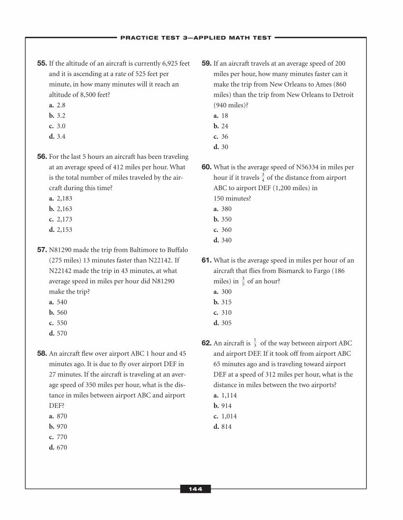
55. If the altitude of an aircraft is currently 6,925 feetand it is ascending at a rate of 525 feet per
minute, in how many minutes will it reach an
altitude of 8,500 feet?
a. 2.8
b. 3.2
c. 3.0
d. 3.4
56. For the last 5 hours an aircraft has been travelingat an average speed of 412 miles per hour. What
is the total number of miles traveled by the air-
craft during this time?
a. 2,183
b. 2,163
c. 2,173
d. 2,153
57. N81290 made the trip from Baltimore to Buffalo(275 miles) 13 minutes faster than N22142. If
N22142 made the trip in 43 minutes, at what
average speed in miles per hour did N81290
make the trip?
a. 540
b. 560
c. 550
d. 570
58. An aircraft flew over airport ABC 1 hour and 45minutes ago. It is due to fly over airport DEF in
27 minutes. If the aircraft is traveling at an aver-
age speed of 350 miles per hour, what is the dis-
tance in miles between airport ABC and airport
DEF?
a. 870
b. 970
c. 770
d. 670
59. If an aircraft travels at an average speed of 200miles per hour, how many minutes faster can it
make the trip from New Orleans to Ames (860
miles) than the trip from New Orleans to Detroit
(940 miles)?
a. 18
b. 24
c. 36
d. 30
60.What is the average speed of N56334 in miles perhour if it travels of the distance from airport
ABC to airport DEF (1,200 miles) in
150 minutes?
a. 380
b. 350
c. 360
d. 340
61.What is the average speed in miles per hour of anaircraft that flies from Bismarck to Fargo (186
miles) in of an hour?
a. 300
b. 315
c. 310
d. 305
62. An aircraft is of the way between airport ABCand airport DEF. If it took off from airport ABC
65 minutes ago and is traveling toward airport
DEF at a speed of 312 miles per hour, what is the
distance in miles between the two airports?
a. 1,114
b. 914
c. 1,014
d. 814
–PRACTICE TEST 3—APPLIED MATH TEST–
144
34
35
13
ATC_2008b:Layout 1 11/24/08 1:16 PM Page 144
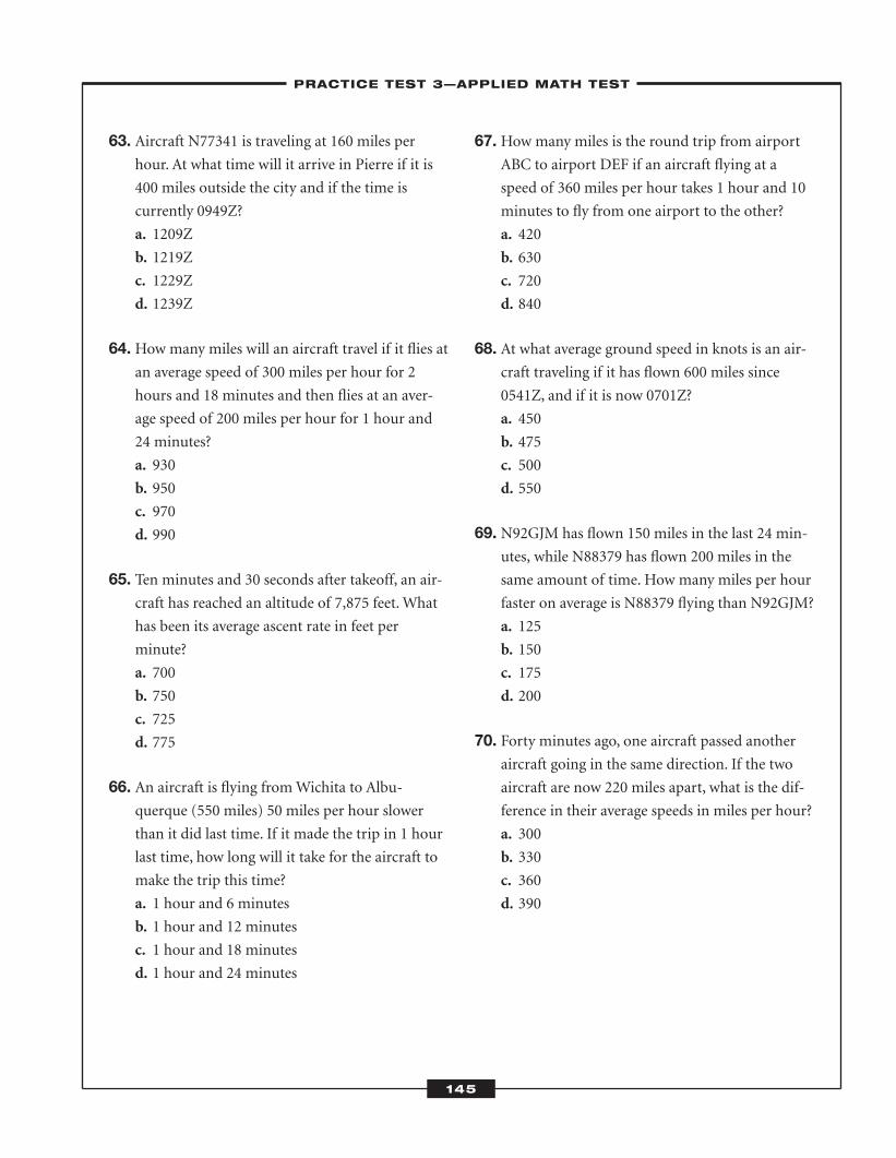
63. Aircraft N77341 is traveling at 160 miles perhour. At what time will it arrive in Pierre if it is
400 miles outside the city and if the time is
currently 0949Z?
a. 1209Z
b. 1219Z
c. 1229Z
d. 1239Z
64. How many miles will an aircraft travel if it flies atan average speed of 300 miles per hour for 2
hours and 18 minutes and then flies at an aver-
age speed of 200 miles per hour for 1 hour and
24 minutes?
a. 930
b. 950
c. 970
d. 990
65. Ten minutes and 30 seconds after takeoff, an air-craft has reached an altitude of 7,875 feet. What
has been its average ascent rate in feet per
minute?
a. 700
b. 750
c. 725
d. 775
66. An aircraft is flying from Wichita to Albu-querque (550 miles) 50 miles per hour slower
than it did last time. If it made the trip in 1 hour
last time, how long will it take for the aircraft to
make the trip this time?
a. 1 hour and 6 minutes
b. 1 hour and 12 minutes
c. 1 hour and 18 minutes
d. 1 hour and 24 minutes
67. How many miles is the round trip from airportABC to airport DEF if an aircraft flying at a
speed of 360 miles per hour takes 1 hour and 10
minutes to fly from one airport to the other?
a. 420
b. 630
c. 720
d. 840
68. At what average ground speed in knots is an air-craft traveling if it has flown 600 miles since
0541Z, and if it is now 0701Z?
a. 450
b. 475
c. 500
d. 550
69. N92GJM has flown 150 miles in the last 24 min-utes, while N88379 has flown 200 miles in the
same amount of time. How many miles per hour
faster on average is N88379 flying than N92GJM?
a. 125
b. 150
c. 175
d. 200
70. Forty minutes ago, one aircraft passed anotheraircraft going in the same direction. If the two
aircraft are now 220 miles apart, what is the dif-
ference in their average speeds in miles per hour?
a. 300
b. 330
c. 360
d. 390
–PRACTICE TEST 3—APPLIED MATH TEST–
145
ATC_2008b:Layout 1 11/24/08 1:16 PM Page 145
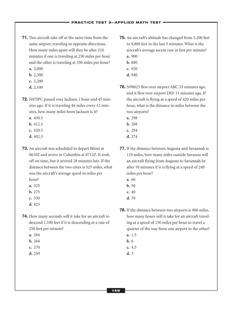
71. Two aircraft take off at the same time from thesame airport, traveling in opposite directions.
How many miles apart will they be after 210
minutes if one is traveling at 250 miles per hour
and the other is traveling at 350 miles per hour?
a. 2,000
b. 2,300
c. 2,200
d. 2,100
72. N87JPC passed over Jackson 1 hour and 45 min-utes ago. If it is traveling 46 miles every 12 min-
utes, how many miles from Jackson is it?
a. 430.5
b. 412.5
c. 420.5
d. 402.5
73. An aircraft was scheduled to depart Biloxi at0610Z and arrive in Columbia at 0712Z. It took
off on time, but it arrived 28 minutes late. If the
distance between the two cities is 525 miles, what
was the aircraft’s average speed in miles per
hour?
a. 325
b. 275
c. 350
d. 425
74. How many seconds will it take for an aircraft todescend 1,100 feet if it is descending at a rate of
250 feet per minute?
a. 284
b. 264
c. 270
d. 250
75. An aircraft’s altitude has changed from 5,200 feetto 9,800 feet in the last 5 minutes. What is the
aircraft’s average ascent rate in feet per minute?
a. 900
b. 880
c. 920
d. 940
76. N90023 flew over airport ABC 53 minutes ago,and it flew over airport DEF 11 minutes ago. If
the aircraft is flying at a speed of 420 miles per
hour, what is the distance in miles between the
two airports?
a. 298
b. 288
c. 294
d. 274
77. If the distance between Augusta and Savannah is110 miles, how many miles outside Savanna will
an aircraft flying from Augusta to Savannah be
after 10 minutes if it is flying at a speed of 240
miles per hour?
a. 60
b. 50
c. 40
d. 70
78. If the distance between two airports is 900 miles,how many hours will it take for an aircraft travel-
ing at a speed of 150 miles per hour to travel a
quarter of the way from one airport to the other?
a. 1.5
b. 6
c. 4.5
d. 3
–PRACTICE TEST 3—APPLIED MATH TEST–
146
ATC_2008b:Layout 1 11/24/08 1:16 PM Page 146
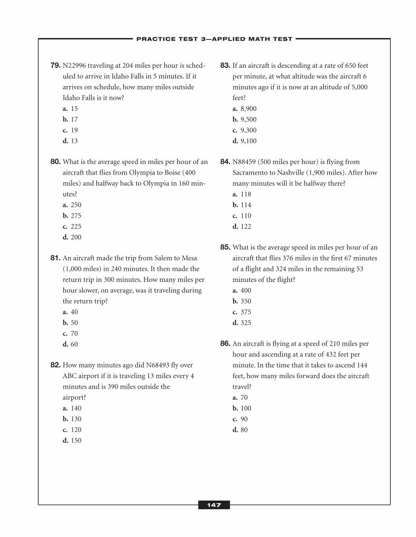
79. N22996 traveling at 204 miles per hour is sched-uled to arrive in Idaho Falls in 5 minutes. If it
arrives on schedule, how many miles outside
Idaho Falls is it now?
a. 15
b. 17
c. 19
d. 13
80.What is the average speed in miles per hour of anaircraft that flies from Olympia to Boise (400
miles) and halfway back to Olympia in 160 min-
utes?
a. 250
b. 275
c. 225
d. 200
81. An aircraft made the trip from Salem to Mesa(1,000 miles) in 240 minutes. It then made the
return trip in 300 minutes. How many miles per
hour slower, on average, was it traveling during
the return trip?
a. 40
b. 50
c. 70
d. 60
82. How many minutes ago did N68493 fly overABC airport if it is traveling 13 miles every 4
minutes and is 390 miles outside the
airport?
a. 140
b. 130
c. 120
d. 150
83. If an aircraft is descending at a rate of 650 feetper minute, at what altitude was the aircraft 6
minutes ago if it is now at an altitude of 5,000
feet?
a. 8,900
b. 9,500
c. 9,300
d. 9,100
84. N88459 (500 miles per hour) is flying fromSacramento to Nashville (1,900 miles). After how
many minutes will it be halfway there?
a. 118
b. 114
c. 110
d. 122
85.What is the average speed in miles per hour of anaircraft that flies 376 miles in the first 67 minutes
of a flight and 324 miles in the remaining 53
minutes of the flight?
a. 400
b. 350
c. 375
d. 325
86. An aircraft is flying at a speed of 210 miles perhour and ascending at a rate of 432 feet per
minute. In the time that it takes to ascend 144
feet, how many miles forward does the aircraft
travel?
a. 70
b. 100
c. 90
d. 80
–PRACTICE TEST 3—APPLIED MATH TEST–
147
ATC_2008b:Layout 1 11/24/08 1:16 PM Page 147
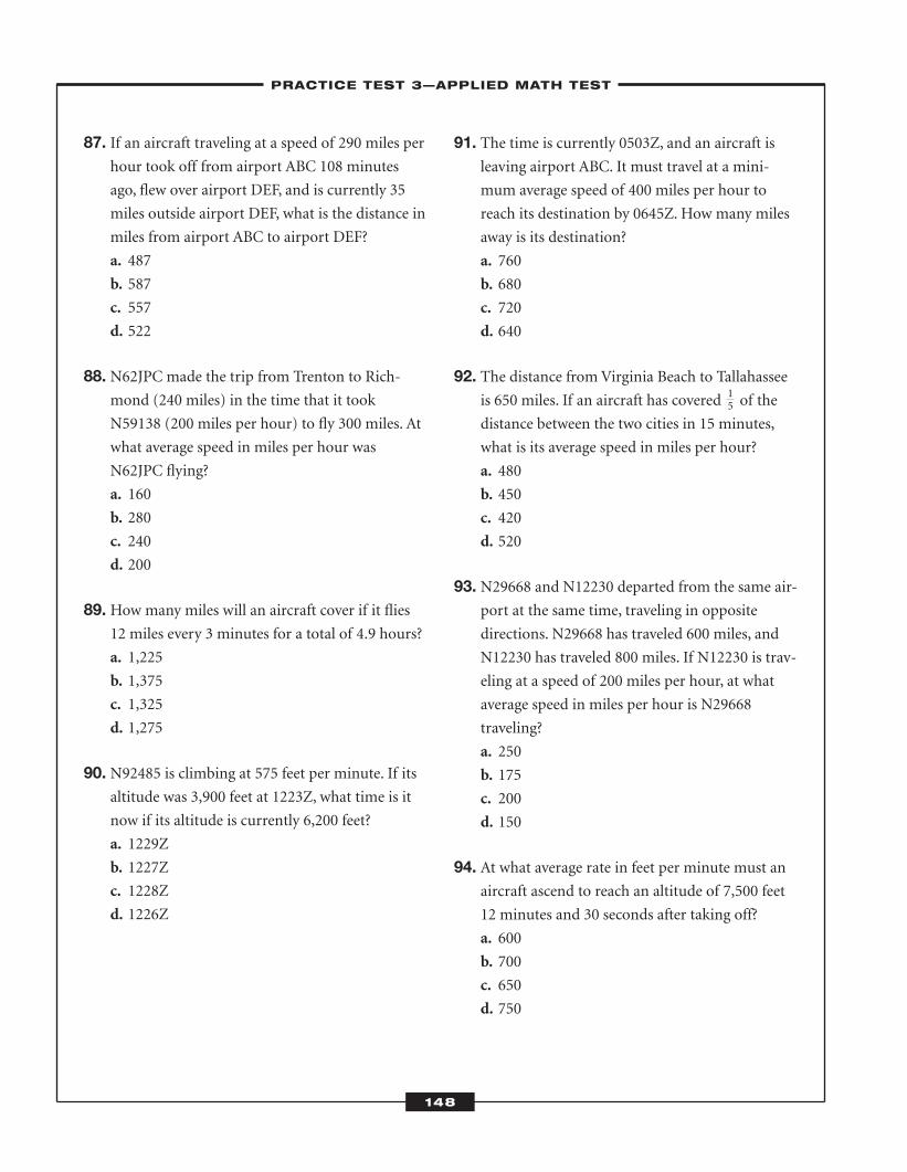
87. If an aircraft traveling at a speed of 290 miles perhour took off from airport ABC 108 minutes
ago, flew over airport DEF, and is currently 35
miles outside airport DEF, what is the distance in
miles from airport ABC to airport DEF?
a. 487
b. 587
c. 557
d. 522
88. N62JPC made the trip from Trenton to Rich-mond (240 miles) in the time that it took
N59138 (200 miles per hour) to fly 300 miles. At
what average speed in miles per hour was
N62JPC flying?
a. 160
b. 280
c. 240
d. 200
89. How many miles will an aircraft cover if it flies12 miles every 3 minutes for a total of 4.9 hours?
a. 1,225
b. 1,375
c. 1,325
d. 1,275
90. N92485 is climbing at 575 feet per minute. If itsaltitude was 3,900 feet at 1223Z, what time is it
now if its altitude is currently 6,200 feet?
a. 1229Z
b. 1227Z
c. 1228Z
d. 1226Z
91. The time is currently 0503Z, and an aircraft isleaving airport ABC. It must travel at a mini-
mum average speed of 400 miles per hour to
reach its destination by 0645Z. How many miles
away is its destination?
a. 760
b. 680
c. 720
d. 640
92. The distance from Virginia Beach to Tallahasseeis 650 miles. If an aircraft has covered of the
distance between the two cities in 15 minutes,
what is its average speed in miles per hour?
a. 480
b. 450
c. 420
d. 520
93. N29668 and N12230 departed from the same air-port at the same time, traveling in opposite
directions. N29668 has traveled 600 miles, and
N12230 has traveled 800 miles. If N12230 is trav-
eling at a speed of 200 miles per hour, at what
average speed in miles per hour is N29668
traveling?
a. 250
b. 175
c. 200
d. 150
94. At what average rate in feet per minute must anaircraft ascend to reach an altitude of 7,500 feet
12 minutes and 30 seconds after taking off?
a. 600
b. 700
c. 650
d. 750
–PRACTICE TEST 3—APPLIED MATH TEST–
148
15
ATC_2008b:Layout 1 11/24/08 1:16 PM Page 148
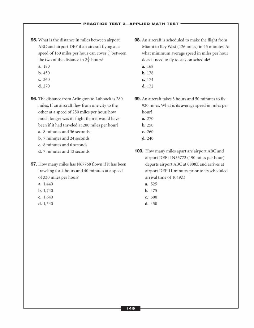
95.What is the distance in miles between airportABC and airport DEF if an aircraft flying at a
speed of 160 miles per hour can cover between
the two of the distance in 2 hours?
a. 180
b. 450
c. 360
d. 270
96. The distance from Arlington to Lubbock is 280miles. If an aircraft flew from one city to the
other at a speed of 250 miles per hour, how
much longer was its flight than it would have
been if it had traveled at 280 miles per hour?
a. 8 minutes and 36 seconds
b. 7 minutes and 24 seconds
c. 8 minutes and 6 seconds
d. 7 minutes and 12 seconds
97. How many miles has N67768 flown if it has beentraveling for 4 hours and 40 minutes at a speed
of 330 miles per hour?
a. 1,440
b. 1,740
c. 1,640
d. 1,540
98. An aircraft is scheduled to make the flight fromMiami to Key West (126 miles) in 45 minutes. At
what minimum average speed in miles per hour
does it need to fly to stay on schedule?
a. 168
b. 178
c. 174
d. 172
99. An aircraft takes 3 hours and 50 minutes to fly920 miles. What is its average speed in miles per
hour?
a. 270
b. 250
c. 260
d. 240
100. How many miles apart are airport ABC andairport DEF if N55772 (190 miles per hour)
departs airport ABC at 0808Z and arrives at
airport DEF 11 minutes prior to its scheduled
arrival time of 1049Z?
a. 525
b. 475
c. 500
d. 450
–PRACTICE TEST 3—APPLIED MATH TEST–
149
34
14
ATC_2008b:Layout 1 11/24/08 1:16 PM Page 149

ATC_2008b:Layout 1 11/24/08 1:16 PM Page 150

Practice Test 3—Applied Math Test
–LEARNINGEXPRESS ANSWER SHEET–
151
1. a b c d
2. a b c d
3. a b c d
4. a b c d
5. a b c d
6. a b c d
7. a b c d
8. a b c d
9. a b c d
10. a b c d
11. a b c d
12. a b c d
13. a b c d
14. a b c d
15. a b c d
16. a b c d
17. a b c d
18. a b c d
19. a b c d
20. a b c d
21. a b c d
22. a b c d
23. a b c d
24. a b c d
25. a b c d
26. a b c d
27. a b c d
28. a b c d
29. a b c d
30. a b c d
31. a b c d
32. a b c d
33. a b c d
34. a b c d
35. a b c d
36. a b c d
37. a b c d
38. a b c d
39. a b c d
40. a b c d
41. a b c d
42. a b c d
43. a b c d
44. a b c d
45. a b c d
46. a b c d
47. a b c d
48. a b c d
49. a b c d
50. a b c d
51. a b c d
52. a b c d
53. a b c d
54. a b c d
55. a b c d
56. a b c d
57. a b c d
58. a b c d
59. a b c d
60. a b c d
61. a b c d
62. a b c d
63. a b c d
64. a b c d
65. a b c d
66. a b c d
67. a b c d
68. a b c d
69. a b c d
70. a b c d
71. a b c d
72. a b c d
73. a b c d
74. a b c d
75. a b c d
76. a b c d
77. a b c d
78. a b c d
79. a b c d
80. a b c d
81. a b c d
82. a b c d
83. a b c d
84. a b c d
85. a b c d
86. a b c d
87. a b c d
88. a b c d
89. a b c d
90. a b c d
91. a b c d
92. a b c d
93. a b c d
94. a b c d
95. a b c d
96. a b c d
97. a b c d
98. a b c d
99. a b c d
100. a b c d
ATC_2008b:Layout 1 11/24/08 1:17 PM Page 151
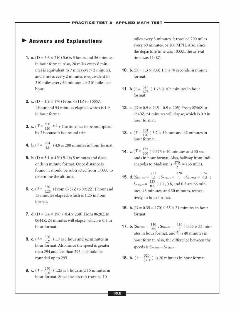
� Answers and Explanat ions
1. a. (D = 5.6 × 210) 5.6 is 5 hours and 36 minutesin hour format. Also, 28 miles every 8 min-
utes is equivalent to 7 miles every 2 minutes,
and 7 miles every 2 minutes is equivalent to
210 miles every 60 minutes, or 210 miles per
hour.
2. c. (D = 1.9 × 170) From 0811Z to 1005Z, 1 hour and 54 minutes elapsed, which is 1.9
in hour format.
3. c. ( ) The time has to be multipliedby 2 because it is a round trip.
4. b. ( ) 4.8 is 288 minutes in hour format.
5. b. (D = 5.1 × 420) 5.1 is 5 minutes and 6 sec-onds in minute format. Once distance is
found, it should be subtracted from 17,000 to
determine the altitude.
6. c. ( ) From 0757Z to 0912Z, 1 hour and15 minutes elapsed, which is 1.25 in hour
format.
7. d. (D = 0.4 × 190 + 0.4 × 230) From 0620Z to0644Z, 24 minutes will elapse, which is 0.4 in
hour format.
8. c. ( ) 1.7 is 1 hour and 42 minutes inhour format. Also, since the speed is greater
than 294 and less than 295, it should be
rounded up to 295.
9. c. ( ) 1.25 is 1 hour and 15 minutes inhour format. Since the aircraft traveled 10
miles every 3 minutes, it traveled 200 miles
every 60 minutes, or 200 MPH. Also, since
the departure time was 1033Z, the arrival
time was 1148Z.
10. b. (D = 1.3 × 900) 1.3 is 78 seconds in minuteformat.
11. b. ( ) 1.75 is 105 minutes in hour format.
12. a. (D = 0.9 × 245 – 0.9 × 205) From 0746Z to0840Z, 54 minutes will elapse, which is 0.9 in
hour format.
13. c. ( ) 3.7 is 3 hours and 42 minutes inhour format.
14. c. ( ) 0.675 is 40 minutes and 30 sec-onds in hour format. Also, halfway from Indi-
anapolis to Madison is = 135 miles.
15. d. (SN44770 = ; SN13121 = ; SN79928 = ;
SN81276 = ) 1.1, 0.8, and 0.5 are 66 min-
utes, 48 minutes, and 30 minutes, respec-
tively, in hour format.
16. b. (D = 0.35 × 170) 0.35 is 21 minutes in hourformat.
17. b. (SN65969 = ; SN44439 = ) 0.55 is 33 min-
utes in hour format, and is 40 minutes in
hour format. Also, the difference between the
speeds is SN65969 – SN44439.
18. b. ( ) is 20 minutes in hour format.
–PRACTICE TEST 3—APPLIED MATH TEST–
152
T = x 2800320
S = 5251.75
T = 703190
T = 135200
S = 320 + 113
2702
110.55
2311.11150.5
2201
1520.8
11023
S = 9844.8
S = 3501.25
S = 5001.7
T = 250200
23
ATC_2008b:Layout 1 11/24/08 1:17 PM Page 152
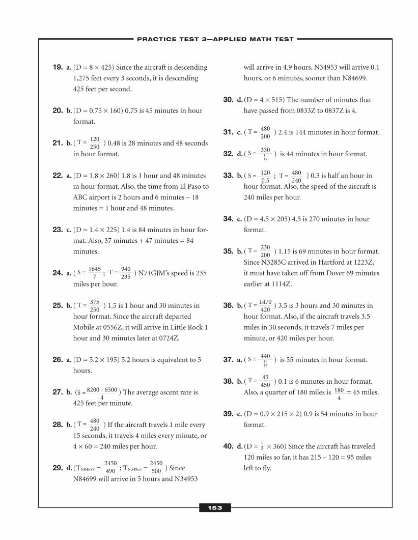
19. a. (D = 8 × 425) Since the aircraft is descending1,275 feet every 3 seconds, it is descending
425 feet per second.
20. b. (D = 0.75 × 160) 0.75 is 45 minutes in hourformat.
21. b. ( ) 0.48 is 28 minutes and 48 secondsin hour format.
22. a. (D = 1.8 × 260) 1.8 is 1 hour and 48 minutesin hour format. Also, the time from El Paso to
ABC airport is 2 hours and 6 minutes – 18
minutes = 1 hour and 48 minutes.
23. c. (D = 1.4 × 225) 1.4 is 84 minutes in hour for-mat. Also, 37 minutes + 47 minutes = 84
minutes.
24. a. ( ; ) N71GJM’s speed is 235miles per hour.
25. b. ( ) 1.5 is 1 hour and 30 minutes inhour format. Since the aircraft departed
Mobile at 0556Z, it will arrive in Little Rock 1
hour and 30 minutes later at 0724Z.
26. a. (D = 5.2 × 195) 5.2 hours is equivalent to 5hours.
27. b. ( ) The average ascent rate is425 feet per minute.
28. b. ( ) If the aircraft travels 1 mile every15 seconds, it travels 4 miles every minute, or
4 × 60 = 240 miles per hour.
29. d. (TN84699 = ; TN34953 = ) SinceN84699 will arrive in 5 hours and N34953
will arrive in 4.9 hours, N34953 will arrive 0.1
hours, or 6 minutes, sooner than N84699.
30. d. (D = 4 × 515) The number of minutes thathave passed from 0833Z to 0837Z is 4.
31. c. ( ) 2.4 is 144 minutes in hour format.
32. d. ( ) is 44 minutes in hour format.
33. b. ( ; ) 0.5 is half an hour inhour format. Also, the speed of the aircraft is
240 miles per hour.
34. c. (D = 4.5 × 205) 4.5 is 270 minutes in hourformat.
35. b. ( ) 1.15 is 69 minutes in hour format.Since N3285C arrived in Hartford at 1223Z,
it must have taken off from Dover 69 minutes
earlier at 1114Z.
36. b. ( ) 3.5 is 3 hours and 30 minutes inhour format. Also, if the aircraft travels 3.5
miles in 30 seconds, it travels 7 miles per
minute, or 420 miles per hour.
37. a. ( ) is 55 minutes in hour format.
38. b. ( ) 0.1 is 6 minutes in hour format.Also, a quarter of 180 miles is = 45 miles.
39. c. (D = 0.9 × 215 × 2) 0.9 is 54 minutes in hourformat.
40. d. (D = × 360) Since the aircraft has traveled120 miles so far, it has 215 – 120 = 95 miles
left to fly.
–PRACTICE TEST 3—APPLIED MATH TEST–
153
T = 120250
S = 16457
T = 375250
S = 8200 - 65004
T = 480240
2450490
2450500
T = 940235
S = 1200.5
T = 230200
T = 1470420
S = 4401112
T = 45450
1804
S = 3301115
T = 480200
T = 480240
13
ATC_2008b:Layout 1 11/24/08 1:17 PM Page 153
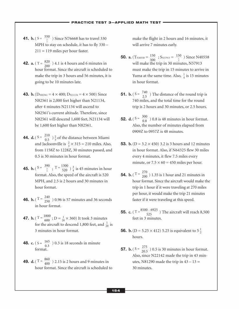
41. b. ( ) Since N76668 has to travel 330MPH to stay on schedule, it has to fly 330 –
211 = 119 miles per hour faster.
42. a. ( ) 4.1 is 4 hours and 6 minutes inhour format. Since the aircraft is scheduled to
make the trip in 3 hours and 56 minutes, it is
going to be 10 minutes late.
43. b. (DN82561 = 4 × 400; DN21134 = 4 × 500) Since
N82561 is 2,000 feet higher than N21134,
after 4 minutes N21134 will ascend to
N82561’s current altitude. Therefore, since
N82561 will descend 1,600 feet, N21134 will
be 1,600 feet higher than N82561.
44. d. ( ) of the distance between Miamiand Jacksonville is × 315 = 210 miles. Also,
from 1158Z to 1228Z, 30 minutes passed, and
0.5 is 30 minutes in hour format.
45. b. ( ; ) is 45 minutes in hourformat. Also, the speed of the aircraft is 520
MPH, and 2.5 is 2 hours and 30 minutes in
hour format.
46. b. ( ) 0.96 is 57 minutes and 36 secondsin hour format.
47. b. ( ; D = × 360) It took 3 minutes
for the aircraft to descend 1,800 feet, and is
3 minutes in hour format.
48. c. ( ) 0.3 is 18 seconds in minute format.
49. d. ( ) 2.15 is 2 hours and 9 minutes inhour format. Since the aircraft is scheduled to
make the flight in 2 hours and 16 minutes, it
will arrive 7 minutes early.
50. a. (TN40558 = ; SN57913 = ) Since N40558will make the trip in 30 minutes, N57913
must make the trip in 15 minutes to arrive in
Yuma at the same time. Also, is 15 minutes
in hour format.
51. b. ( ) The distance of the round trip is740 miles, and the total time for the round
trip is 2 hours and 30 minutes, or 2.5 hours.
52. d. ( ) 0.8 is 48 minutes in hour format.Also, the number of minutes elapsed from
0909Z to 0957Z is 48 minutes.
53. b. (D = 3.2 × 450) 3.2 is 3 hours and 12 minutesin hour format. Also, if N64325 flew 30 miles
every 4 minutes, it flew 7.5 miles every
minute, or 7.5 × 60 = 450 miles per hour.
54. b. ( ) 1.35 is 1 hour and 21 minutes inhour format. Since the aircraft would make the
trip in 1 hour if it were traveling at 270 miles
per hour, it would make the trip 21 minutes
faster if it were traveling at this speed.
55. c. ( ) The aircraft will reach 8,500feet in 3 minutes.
56. b. (D = 5.25 × 412) 5.25 is equivalent to 5hours.
57. b. ( ) 0.5 is 30 minutes in hour format.Also, since N22142 made the trip in 43 min-
utes, N81290 made the trip in 43 – 13 =
30 minutes.
–PRACTICE TEST 3—APPLIED MATH TEST–
154
S = 55053
T = 820200
S = 7402.5
S = 3000.8
T = 270200
S = 27520.5
T =8500 - 6925525
150300
15014
S = 2100.5
S = 39034
T = 240250
T = 1800600
S = 1650.3
T = 860400
T = 1300520
23
14
23
34
120
120
12
ATC_2008b:Layout 1 11/24/08 1:17 PM Page 154
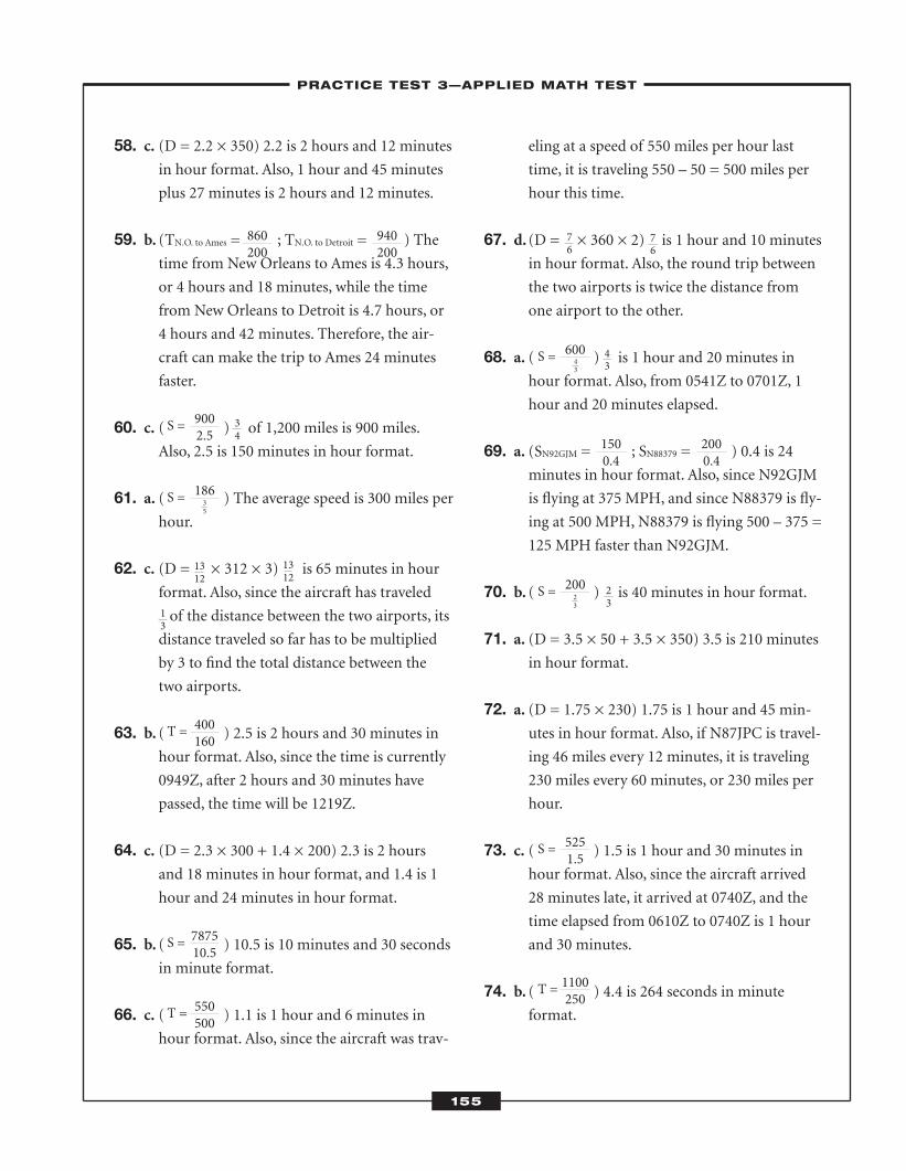
58. c. (D = 2.2 × 350) 2.2 is 2 hours and 12 minutesin hour format. Also, 1 hour and 45 minutes
plus 27 minutes is 2 hours and 12 minutes.
59. b. (TN.O. to Ames = ; TN.O. to Detroit = ) Thetime from New Orleans to Ames is 4.3 hours,
or 4 hours and 18 minutes, while the time
from New Orleans to Detroit is 4.7 hours, or
4 hours and 42 minutes. Therefore, the air-
craft can make the trip to Ames 24 minutes
faster.
60. c. ( ) of 1,200 miles is 900 miles.Also, 2.5 is 150 minutes in hour format.
61. a. ( ) The average speed is 300 miles perhour.
62. c. (D = × 312 × 3) is 65 minutes in hour
format. Also, since the aircraft has traveled
of the distance between the two airports, its
distance traveled so far has to be multiplied
by 3 to find the total distance between the
two airports.
63. b. ( ) 2.5 is 2 hours and 30 minutes inhour format. Also, since the time is currently
0949Z, after 2 hours and 30 minutes have
passed, the time will be 1219Z.
64. c. (D = 2.3 × 300 + 1.4 × 200) 2.3 is 2 hoursand 18 minutes in hour format, and 1.4 is 1
hour and 24 minutes in hour format.
65. b. ( ) 10.5 is 10 minutes and 30 secondsin minute format.
66. c. ( ) 1.1 is 1 hour and 6 minutes inhour format. Also, since the aircraft was trav-
eling at a speed of 550 miles per hour last
time, it is traveling 550 – 50 = 500 miles per
hour this time.
67. d. (D = × 360 × 2) is 1 hour and 10 minutesin hour format. Also, the round trip between
the two airports is twice the distance from
one airport to the other.
68. a. ( ) is 1 hour and 20 minutes inhour format. Also, from 0541Z to 0701Z, 1
hour and 20 minutes elapsed.
69. a. (SN92GJM = ; SN88379 = ) 0.4 is 24minutes in hour format. Also, since N92GJM
is flying at 375 MPH, and since N88379 is fly-
ing at 500 MPH, N88379 is flying 500 – 375 =
125 MPH faster than N92GJM.
70. b. ( ) is 40 minutes in hour format.
71. a. (D = 3.5 × 50 + 3.5 × 350) 3.5 is 210 minutesin hour format.
72. a. (D = 1.75 × 230) 1.75 is 1 hour and 45 min-utes in hour format. Also, if N87JPC is travel-
ing 46 miles every 12 minutes, it is traveling
230 miles every 60 minutes, or 230 miles per
hour.
73. c. ( ) 1.5 is 1 hour and 30 minutes inhour format. Also, since the aircraft arrived
28 minutes late, it arrived at 0740Z, and the
time elapsed from 0610Z to 0740Z is 1 hour
and 30 minutes.
74. b. ( ) 4.4 is 264 seconds in minute format.
–PRACTICE TEST 3—APPLIED MATH TEST–
155
860200
S = 9002.5
S = 60043
S = 20023
S = 5251.5
T = 1100250
S = 18635
T = 400160
S = 787510.5
T = 550500
940200
1500.4
2000.4
34
76
43
23
76
13
1312
1312
ATC_2008b:Layout 1 11/24/08 1:17 PM Page 155
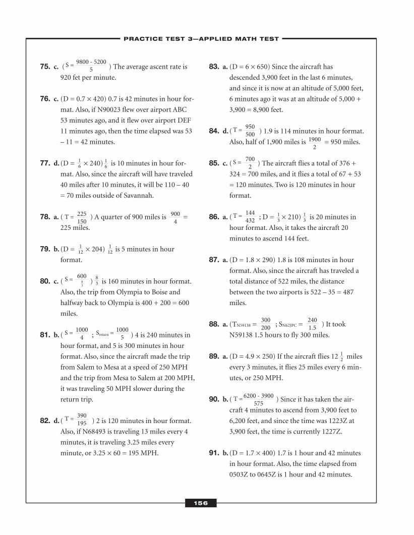
75. c. ( ) The average ascent rate is920 fet per minute.
76. c. (D = 0.7 × 420) 0.7 is 42 minutes in hour for-mat. Also, if N90023 flew over airport ABC
53 minutes ago, and it flew over airport DEF
11 minutes ago, then the time elapsed was 53
– 11 = 42 minutes.
77. d. (D = × 240) is 10 minutes in hour for-
mat. Also, since the aircraft will have traveled
40 miles after 10 minutes, it will be 110 – 40
= 70 miles outside of Savannah.
78. a. ( ) A quarter of 900 miles is =225 miles.
79. b. (D = × 204) is 5 minutes in hour
format.
80. c. ( ) is 160 minutes in hour format.
Also, the trip from Olympia to Boise and
halfway back to Olympia is 400 + 200 = 600
miles.
81. b. ( ; ) 4 is 240 minutes in
hour format, and 5 is 300 minutes in hour
format. Also, since the aircraft made the trip
from Salem to Mesa at a speed of 250 MPH
and the trip from Mesa to Salem at 200 MPH,
it was traveling 50 MPH slower during the
return trip.
82. d. ( ) 2 is 120 minutes in hour format.Also, if N68493 is traveling 13 miles every 4
minutes, it is traveling 3.25 miles every
minute, or 3.25 × 60 = 195 MPH.
83. a. (D = 6 × 650) Since the aircraft hasdescended 3,900 feet in the last 6 minutes,
and since it is now at an altitude of 5,000 feet,
6 minutes ago it was at an altitude of 5,000 +
3,900 = 8,900 feet.
84. d. ( ) 1.9 is 114 minutes in hour format.Also, half of 1,900 miles is = 950 miles.
85. c. ( ) The aircraft flies a total of 376 +324 = 700 miles, and it flies a total of 67 + 53
= 120 minutes. Two is 120 minutes in hour
format.
86. a. ( ; D = × 210) is 20 minutes inhour format. Also, it takes the aircraft 20
minutes to ascend 144 feet.
87. a. (D = 1.8 × 290) 1.8 is 108 minutes in hourformat. Also, since the aircraft has traveled a
total distance of 522 miles, the distance
between the two airports is 522 – 35 = 487
miles.
88. a. (TN59138 = ; SN62JPC = ) It tookN59138 1.5 hours to fly 300 miles.
89. a. (D = 4.9 × 250) If the aircraft flies 12 milesevery 3 minutes, it flies 25 miles every 6 min-
utes, or 250 MPH.
90. b. ( ) Since it has taken the air-craft 4 minutes to ascend from 3,900 feet to
6,200 feet, and since the time was 1223Z at
3,900 feet, the time is currently 1227Z.
91. b. (D = 1.7 × 400) 1.7 is 1 hour and 42 minutesin hour format. Also, the time elapsed from
0503Z to 0645Z is 1 hour and 42 minutes.
–PRACTICE TEST 3—APPLIED MATH TEST–
156
T = 225150
T = 950500
S = 7002
T = 144432
300200
T = 6200 - 3900575
2401.5
19002
S = 60083
S = 10004
T = 390195
Sreturn = 10005
9004
16
16
112
83
12
13
13
112
S = 9800 - 52005
ATC_2008b:Layout 1 11/24/08 1:17 PM Page 156
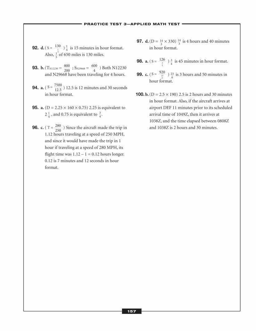
92. d. ( ) is 15 minutes in hour format.Also, of 650 miles is 130 miles.
93. b. (TN12230 = ; SN29668 = ) Both N12230and N29668 have been traveling for 4 hours.
94. a. ( ) 12.5 is 12 minutes and 30 secondsin hour format.
95. a. (D = 2.25 × 160 × 0.75) 2.25 is equivalent to2 , and 0.75 is equivalent to .
96. c. ( ) Since the aircraft made the trip in1.12 hours traveling at a speed of 250 MPH,
and since it would have made the trip in 1
hour if traveling at a speed of 280 MPH, its
flight time was 1.12 – 1 = 0.12 hours longer.
0.12 is 7 minutes and 12 seconds in hour
format.
97. d. (D = × 330) is 4 hours and 40 minutes
in hour format.
98. a. ( ) is 45 minutes in hour format.
99. c. ( ) is 3 hours and 50 minutes inhour format.
100.b. (D = 2.5 × 190) 2.5 is 2 hours and 30 minutesin hour format. Also, if the aircraft arrives at
airport DEF 11 minutes prior to its scheduled
arrival time of 1049Z, then it arrives at
1038Z, and the time elapsed between 0808Z
and 1038Z is 2 hours and 30 minutes.
–PRACTICE TEST 3—APPLIED MATH TEST–
157
800200
S = 750012.5
T = 280250
S = 12634
S = 920236
6004
S = 13014
14
15
14
34
143
143
34
236
ATC_2008b:Layout 1 11/24/08 1:17 PM Page 157

ATC_2008b:Layout 1 11/24/08 1:17 PM Page 158
Controllers must be able to interpret visual information and make good decisions based on this
information—and they must be able to do this very quickly. The Scan Test and the Dial Read-
ing Test assess your ability to interpret bits of information similar to the kind you will see on the
job. Keep in mind that both tests are administered on a computer and are speed tests, so you should work as
quickly as you can without sacrificing accuracy. You will answer 20 multiple-choice questions on the Dial Test.
For the Scan Test, you will have to use numbers on the keypad of a computer keyboard to enter as many answers
as you can. If you practice using a keypad, it will help your performance on the test.
� Scan
Controllers sometimes work very quickly. They might look at a radar screen and decide to reroute a plane because
of traffic or an oncoming storm. The Scan Test assesses your ability to process small chunks of information quickly
and accurately. To do well on this test, you need to be alert and enter numbers quickly using a keypad. The test
Scan and DialReading
CHAPTER SUMMARYThe Scan Test and the Dial Reading Test are cognitive tests on the AT-
SAT. On the Scan Test, you will watch data blocks on a computer
screen. Each data block has an identification number on the top and
a number on the bottom. On the bottom of your screen will be a num-
ber range. You will key in the identification number for any data block
with a number on the bottom that is outside this range. On the Dial
Reading Test, you will read dials similar to those you might see on the
instrument panel in the cockpit of an aircraft.
7C H A P T E R
159
ATC_2008b:Layout 1 11/24/08 1:17 PM Page 159
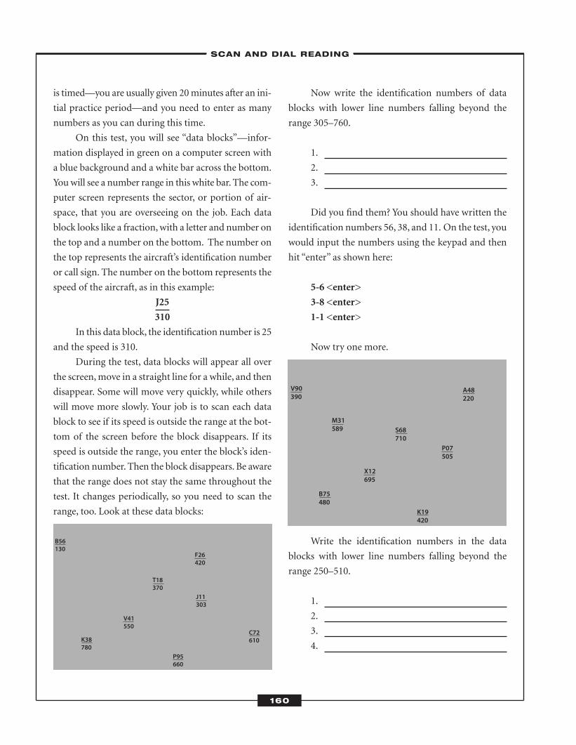
is timed—you are usually given 20 minutes after an ini-
tial practice period—and you need to enter as many
numbers as you can during this time.
On this test, you will see “data blocks”—infor-
mation displayed in green on a computer screen with
a blue background and a white bar across the bottom.
You will see a number range in this white bar. The com-
puter screen represents the sector, or portion of air-
space, that you are overseeing on the job. Each data
block looks like a fraction, with a letter and number on
the top and a number on the bottom. The number on
the top represents the aircraft’s identification number
or call sign. The number on the bottom represents the
speed of the aircraft, as in this example:
J25
310
In this data block, the identification number is 25
and the speed is 310.
During the test, data blocks will appear all over
the screen, move in a straight line for a while, and then
disappear. Some will move very quickly, while others
will move more slowly. Your job is to scan each data
block to see if its speed is outside the range at the bot-
tom of the screen before the block disappears. If its
speed is outside the range, you enter the block’s iden-
tification number. Then the block disappears. Be aware
that the range does not stay the same throughout the
test. It changes periodically, so you need to scan the
range, too. Look at these data blocks:
Now write the identification numbers of data
blocks with lower line numbers falling beyond the
range 305–760.
1.
2.
3.
Did you find them? You should have written the
identification numbers 56, 38, and 11. On the test, you
would input the numbers using the keypad and then
hit “enter” as shown here:
5-6 <enter>
3-8 <enter>
1-1 <enter>
Now try one more.
Write the identification numbers in the data
blocks with lower line numbers falling beyond the
range 250–510.
1.
2.
3.
4.
V90390
A48220
B75480
X12695
S68710
P07505
K19420
M31589
B56130
F26420
K38780
V41550
T18370
J11303
P95660
C72610
–SCAN AND DIAL READING–
160
ATC_2008b:Layout 1 11/24/08 1:17 PM Page 160
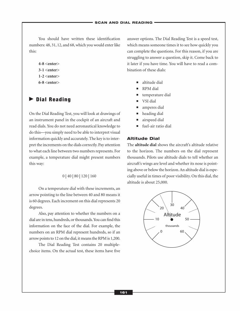
You should have written these identification
numbers: 48, 31, 12, and 68, which you would enter like
this:
4-8 <enter>
3-1 <enter>
1-2 <enter>
6-8 <enter>
� Dial Reading
On the Dial Reading Test, you will look at drawings of
an instrument panel in the cockpit of an aircraft and
read dials. You do not need aeronautical knowledge to
do this—you simply need to be able to interpret visual
information quickly and accurately. The key is to inter-
pret the increments on the dials correctly. Pay attention
to what each line between two numbers represents. For
example, a temperature dial might present numbers
this way:
0 | 40�| 80 | 120 | 160
On a temperature dial with these increments, an
arrow pointing to the line between 40 and 80 means it
is 60 degrees. Each increment on this dial represents 20
degrees.
Also, pay attention to whether the numbers on a
dial are in tens, hundreds, or thousands. You can find this
information on the face of the dial. For example, the
numbers on an RPM dial represent hundreds, so if an
arrow points to 12 on the dial, it means the RPM is 1,200.
The Dial Reading Test contains 20 multiple-
choice items. On the actual test, these items have five
answer options. The Dial Reading Test is a speed test,
which means someone times it to see how quickly you
can complete the questions. For this reason, if you are
struggling to answer a question, skip it. Come back to
it later if you have time. You will have to read a com-
bination of these dials:
� altitude dial � RPM dial � temperature dial � VSI dial � amperes dial � heading dial � airspeed dial � fuel-air ratio dial
Altitude Dial
The altitude dial shows the aircraft’s altitude relative
to the horizon. The numbers on the dial represent
thousands. Pilots use altitude dials to tell whether an
aircraft’s wings are level and whether its nose is point-
ing above or below the horizon. An altitude dial is espe-
cially useful in times of poor visibility. On this dial, the
altitude is about 25,000.
–SCAN AND DIAL READING–
161
0
10 50
20
60
4030
Altitude
thousands
ATC_2008b:Layout 1 11/24/08 1:17 PM Page 161
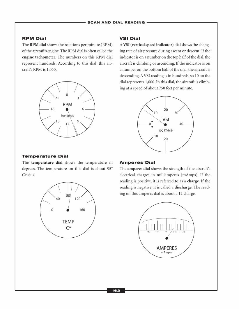
RPM Dial
The RPM dial shows the rotations per minute (RPM)
of the aircraft’s engine. The RPM dial is often called the
engine tachometer. The numbers on this RPM dial
represent hundreds. According to this dial, this air-
craft’s RPM is 1,050.
Temperature Dial
The temperature dial shows the temperature in
degrees. The temperature on this dial is about 95°
Celsius.
VSI Dial
A VSI (vertical speed indicator) dial shows the chang-
ing rate of air pressure during ascent or descent. If the
indicator is on a number on the top half of the dial, the
aircraft is climbing or ascending. If the indicator is on
a number on the bottom half of the dial, the aircraft is
descending. A VSI reading is in hundreds, so 10 on the
dial represents 1,000. In this dial, the aircraft is climb-
ing at a speed of about 750 feet per minute.
Amperes Dial
The amperes dial shows the strength of the aircraft’s
electrical charges in milliamperes (mAmps). If the
reading is positive, it is referred to as a charge. If the
reading is negative, it is called a discharge. The read-
ing on this amperes dial is about a 12 charge.
10
0 40
10 3020
20
VSI
100 FT/MIN
-30 -15 0 +15 +30
AMPERESmAmpes
15
18 6
21
9
30
12
RPM
hundreds
0 160
40 12080
TEMPCº
–SCAN AND DIAL READING–
162
ATC_2008b:Layout 1 11/24/08 1:17 PM Page 162
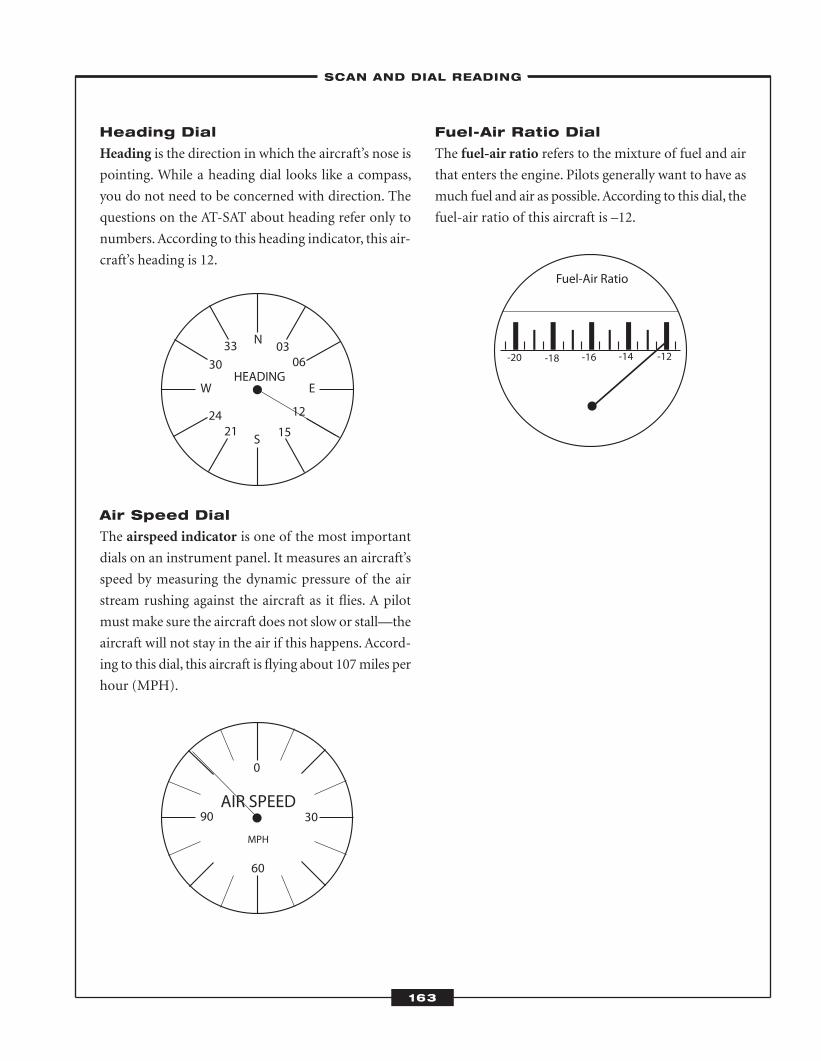
Heading Dial
Heading is the direction in which the aircraft’s nose is
pointing. While a heading dial looks like a compass,
you do not need to be concerned with direction. The
questions on the AT-SAT about heading refer only to
numbers. According to this heading indicator, this air-
craft’s heading is 12.
Air Speed Dial
The airspeed indicator is one of the most important
dials on an instrument panel. It measures an aircraft’s
speed by measuring the dynamic pressure of the air
stream rushing against the aircraft as it flies. A pilot
must make sure the aircraft does not slow or stall—the
aircraft will not stay in the air if this happens. Accord-
ing to this dial, this aircraft is flying about 107 miles per
hour (MPH).
Fuel-Air Ratio Dial
The fuel-air ratio refers to the mixture of fuel and air
that enters the engine. Pilots generally want to have as
much fuel and air as possible. According to this dial, the
fuel-air ratio of this aircraft is –12.
90 30
0
60
AIR SPEED
MPH
-12-14-16-18-20
Fuel-Air Ratio
W E
N
S
HEADING
3330
2421 15
12
0603
–SCAN AND DIAL READING–
163
ATC_2008b:Layout 1 11/24/08 1:17 PM Page 163
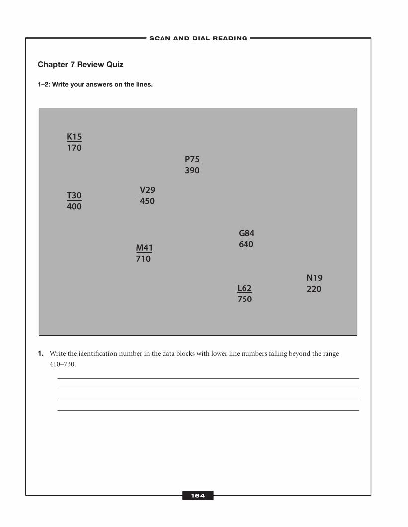
164
Chapter 7 Review Quiz
1–2: Write your answers on the lines.
1. Write the identification number in the data blocks with lower line numbers falling beyond the range 410–730.
K15170
T30400
G84640
P75390
N19220L62
750
V29450
M41710
–SCAN AND DIAL READING–
ATC_2008b:Layout 1 11/24/08 1:17 PM Page 164
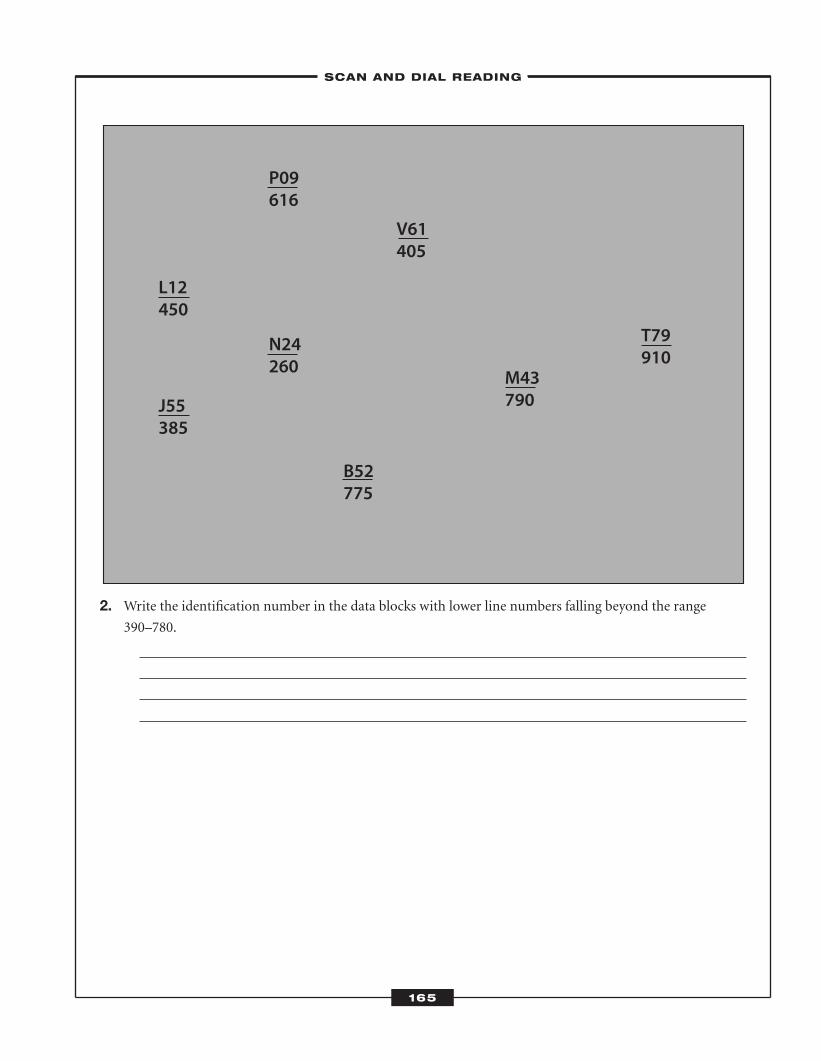
165
2. Write the identification number in the data blocks with lower line numbers falling beyond the range 390–780.
L12450
J55385
M43790
V61405
T79910
B52775
N24260
P09616
–SCAN AND DIAL READING–
ATC_2008b:Layout 1 11/24/08 1:17 PM Page 165
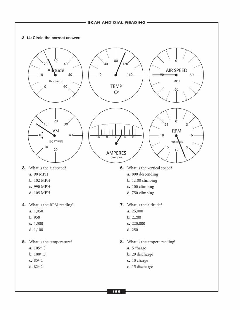
3–14: Circle the correct answer.
3. What is the air speed?a. 90 MPH
b. 102 MPH
c. 990 MPH
d. 105 MPH
4. What is the RPM reading?a. 1,050
b. 950
c. 1,500
d. 1,100
5. What is the temperature? a. 105º C
b. 100º C
c. 85º C
d. 82º C
6. What is the vertical speed?a. 800 descending
b. 1,100 climbing
c. 100 climbing
d. 750 climbing
7. What is the altitude? a. 25,000
b. 2,200
c. 220,000
d. 250
8. What is the ampere reading? a. 5 charge
b. 20 discharge
c. 10 charge
d. 15 discharge
10
0 40
10 3020
20
VSI
100 FT/MIN
0
10 50
20
60
4030
Altitude
thousands
0 160
40 12080
TEMPCº
-30 -15 0 +15 +30
AMPERESmAmpes
15
18 6
21
9
30
12
RPM
hundreds
90 30
0
60
AIR SPEED
MPH
–SCAN AND DIAL READING–
166
ATC_2008b:Layout 1 11/24/08 1:17 PM Page 166
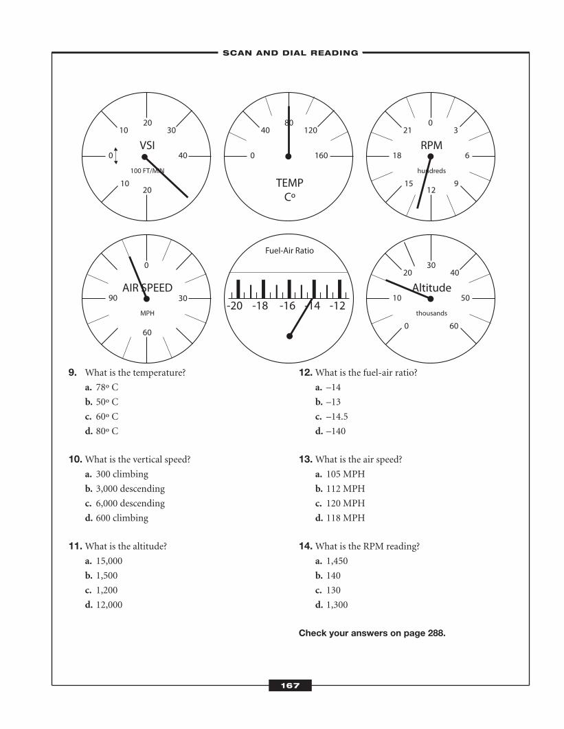
9. What is the temperature?a. 78º C
b. 50º C
c. 60º C
d. 80º C
10.What is the vertical speed?a. 300 climbing
b. 3,000 descending
c. 6,000 descending
d. 600 climbing
11.What is the altitude?a. 15,000
b. 1,500
c. 1,200
d. 12,000
12.What is the fuel-air ratio?a. –14
b. –13
c. –14.5
d. –140
13.What is the air speed?a. 105 MPH
b. 112 MPH
c. 120 MPH
d. 118 MPH
14.What is the RPM reading?a. 1,450
b. 140
c. 130
d. 1,300
Check your answers on page 288.
10
0 40
10 3020
20
VSI
100 FT/MIN
0
10 50
20
60
4030
Altitude
thousands
0 160
40 12080
TEMPCº
15
18 6
21
9
30
12
RPM
hundreds
90 30
0
60
AIR SPEED
MPH-12-14-16-18-20
Fuel-Air Ratio
–SCAN AND DIAL READING–
167
ATC_2008b:Layout 1 11/24/08 1:17 PM Page 167

ATC_2008b:Layout 1 11/24/08 1:17 PM Page 168
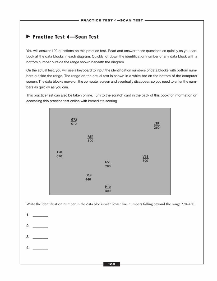
� Pract ice Test 4—Scan Test
You will answer 100 questions on this practice test. Read and answer these questions as quickly as you can.
Look at the data blocks in each diagram. Quickly jot down the identification number of any data block with a
bottom number outside the range shown beneath the diagram.
On the actual test, you will use a keyboard to input the identification numbers of data blocks with bottom num-
bers outside the range. The range on the actual test is shown in a white bar on the bottom of the computer
screen. The data blocks move on the computer screen and eventually disappear, so you need to enter the num-
bers as quickly as you can.
This practice test can also be taken online. Turn to the scratch card in the back of this book for information on
accessing this practice test online with immediate scoring.
Write the identification number in the data blocks with lower line numbers falling beyond the range 270–430.
1. ________
2. ________
3. ________
4. ________
T50670
D19440
I22280
P10400
V63390
J39260
A81300
G72510
–PRACTICE TEST 4—SCAN TEST–
169
ATC_2008b:Layout 1 11/24/08 1:17 PM Page 169
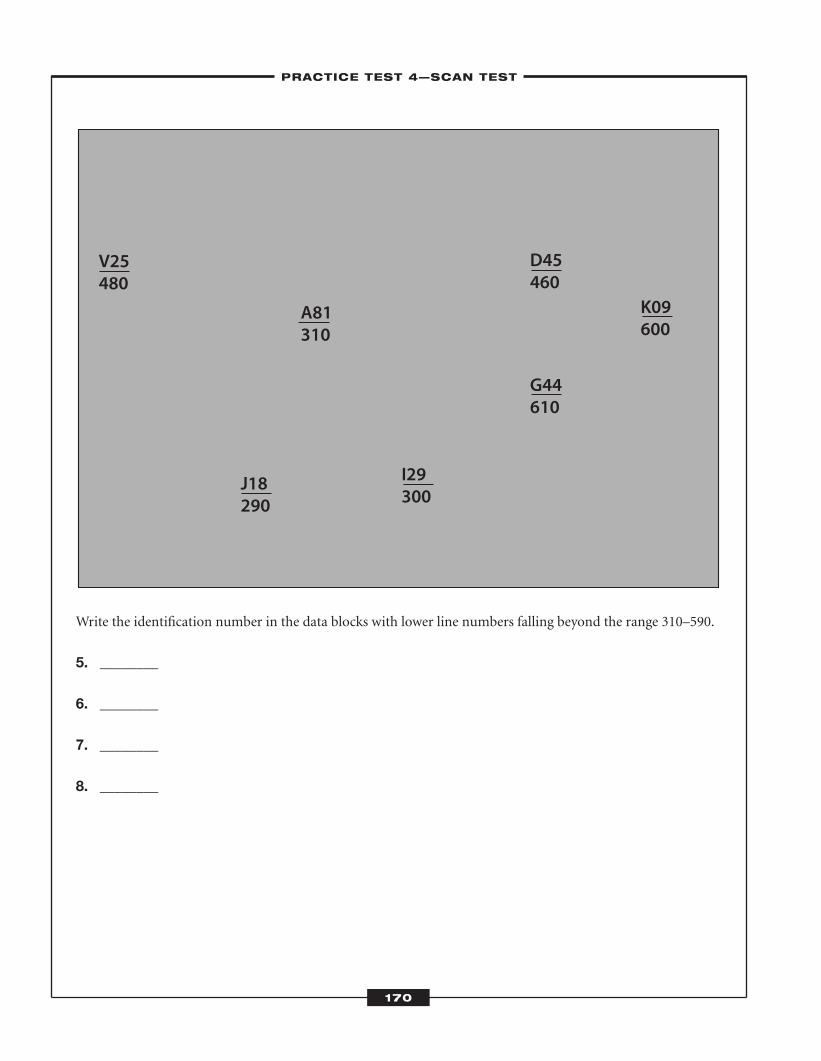
Write the identification number in the data blocks with lower line numbers falling beyond the range 310–590.
5. ________
6. ________
7. ________
8. ________
V25480
J18290
I29300
G44610
D45460
K09600
A81310
–PRACTICE TEST 4—SCAN TEST–
170
ATC_2008b:Layout 1 11/24/08 1:17 PM Page 170
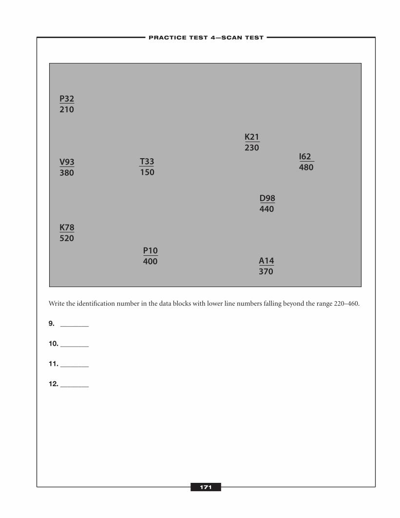
Write the identification number in the data blocks with lower line numbers falling beyond the range 220–460.
9. ________
10. ________
11. ________
12. ________
P32210
V93380
K78520
P10400 A14
370
D98440
K21230
I62480
T33150
–PRACTICE TEST 4—SCAN TEST–
171
ATC_2008b:Layout 1 11/24/08 1:17 PM Page 171
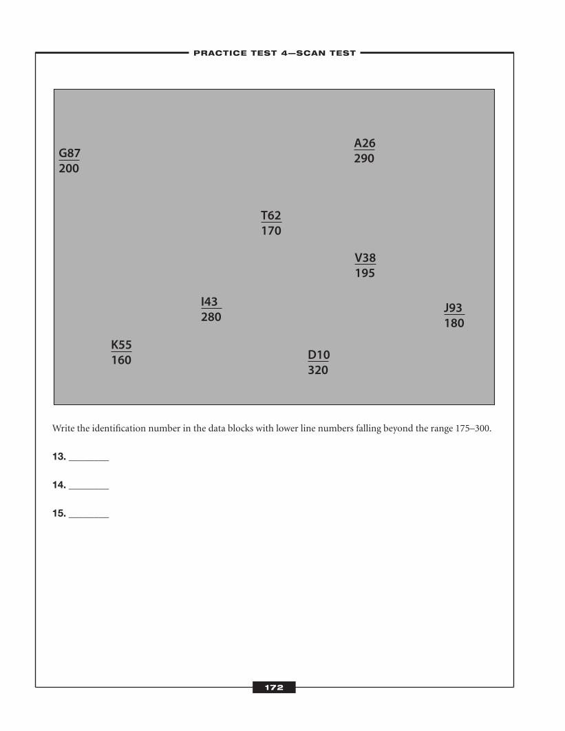
Write the identification number in the data blocks with lower line numbers falling beyond the range 175–300.
13. ________
14. ________
15. ________
G87200
K55160
I43280
D10320
T62170
A26290
V38195
J93180
172
–PRACTICE TEST 4—SCAN TEST–
ATC_2008b:Layout 1 11/24/08 1:17 PM Page 172
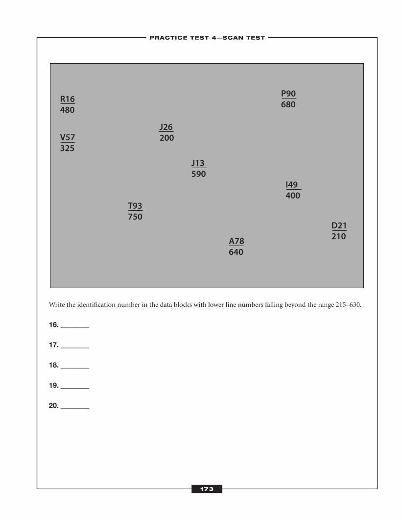
Write the identification number in the data blocks with lower line numbers falling beyond the range 215–630.
16. ________
17. ________
18. ________
19. ________
20. ________
R16480
V57325
T93750
A78640
D21210
I49400
J13590
P90680
J26200
173
–PRACTICE TEST 4—SCAN TEST–
ATC_2008b:Layout 1 11/24/08 1:17 PM Page 173
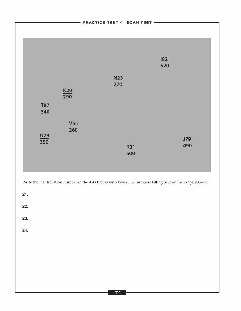
Write the identification number in the data blocks with lower line numbers falling beyond the range 280–492.
21. ________
22. ________
23. ________
24. ________
T87340
K20290
N23270
U29350
V65260
R31500
I82520
J79490
–PRACTICE TEST 4—SCAN TEST–
174
ATC_2008b:Layout 1 11/24/08 1:17 PM Page 174
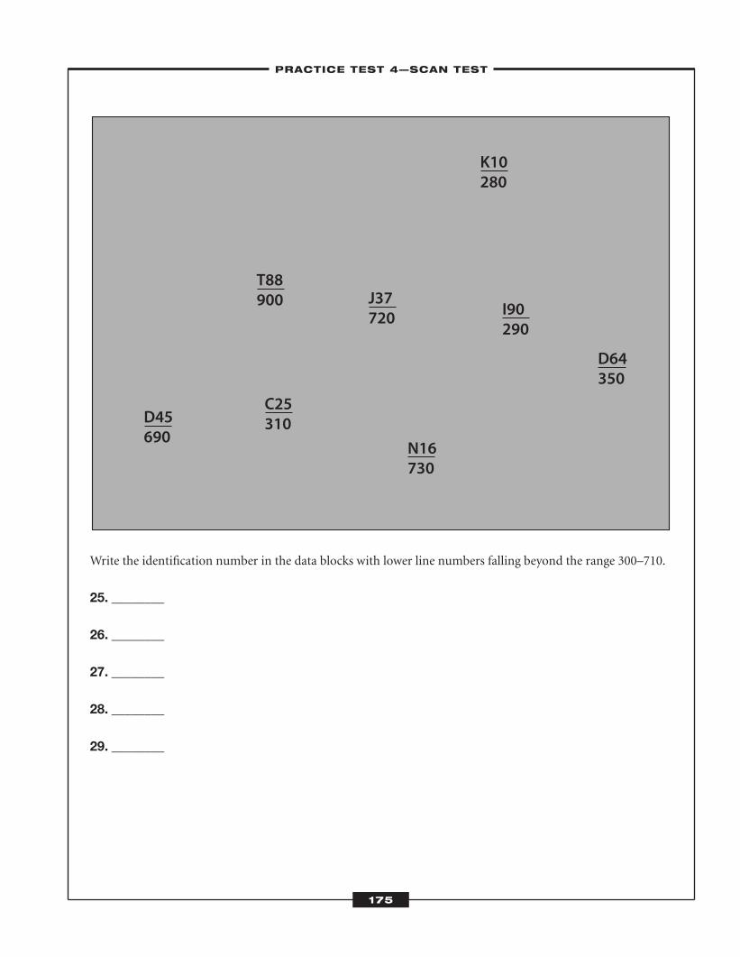
Write the identification number in the data blocks with lower line numbers falling beyond the range 300–710.
25. ________
26. ________
27. ________
28. ________
29. ________
D45690
C25310
J37720
K10280
I90290
D64350
N16730
T88900
–PRACTICE TEST 4—SCAN TEST–
175
ATC_2008b:Layout 1 11/24/08 1:17 PM Page 175
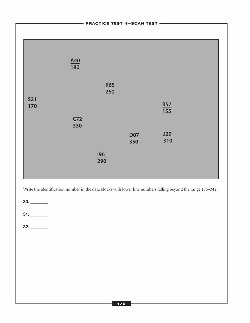
Write the identification number in the data blocks with lower line numbers falling beyond the range 175–342.
30. ________
31. ________
32. ________
C72330
I96290
R65260
A40180
B57155
J29310
D07350
S21170
176
–PRACTICE TEST 4—SCAN TEST–
ATC_2008b:Layout 1 11/24/08 1:17 PM Page 176
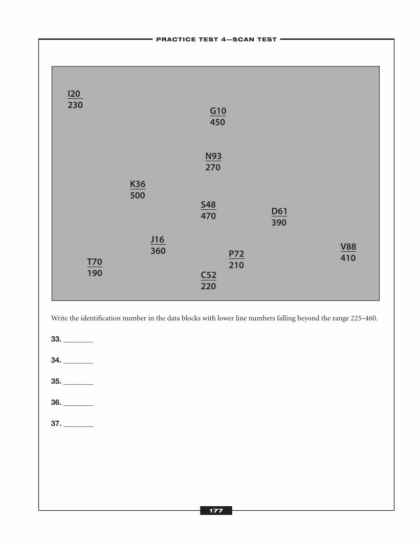
Write the identification number in the data blocks with lower line numbers falling beyond the range 225–460.
33. ________
34. ________
35. ________
36. ________
37. ________
I20230
T70190
K36500
J16360
C52220
S48470
G10450
N93270
P72210
D61390
V88410
–PRACTICE TEST 4—SCAN TEST–
177
ATC_2008b:Layout 1 11/24/08 1:17 PM Page 177

Write the identification number in the data blocks with lower line numbers falling beyond the range 290–450.
38. ________
39. ________
40. ________
41. ________
T34300
L22440 P98
490
I75410
K55290 K81
500 D10320
B27220
C53350
J46280
–PRACTICE TEST 4—SCAN TEST–
178
ATC_2008b:Layout 1 11/24/08 1:17 PM Page 178
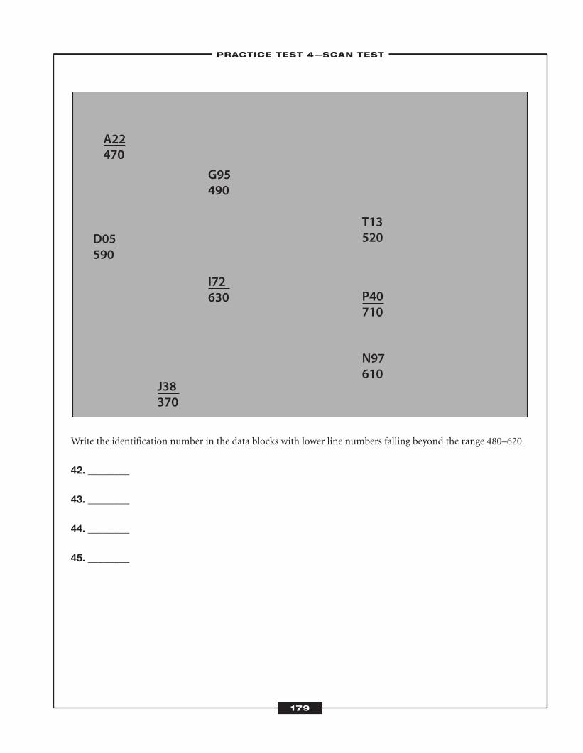
Write the identification number in the data blocks with lower line numbers falling beyond the range 480–620.
42. ________
43. ________
44. ________
45. ________
A22470
G95490
I72630
J38370
T13520
P40710
N97610
D05590
–PRACTICE TEST 4—SCAN TEST–
179
ATC_2008b:Layout 1 11/24/08 1:17 PM Page 179
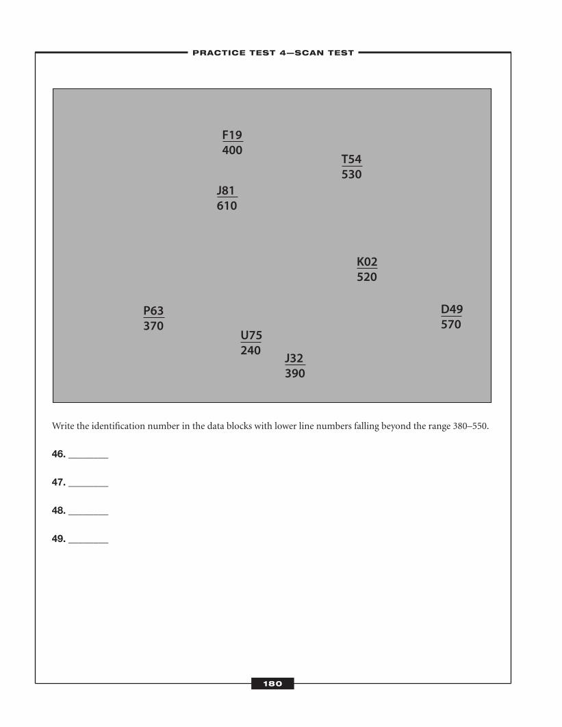
Write the identification number in the data blocks with lower line numbers falling beyond the range 380–550.
46. ________
47. ________
48. ________
49. ________
P63370
F19400
J81610
U75240
J32390
T54530
K02520
D49570
–PRACTICE TEST 4—SCAN TEST–
180
ATC_2008b:Layout 1 11/24/08 1:17 PM Page 180
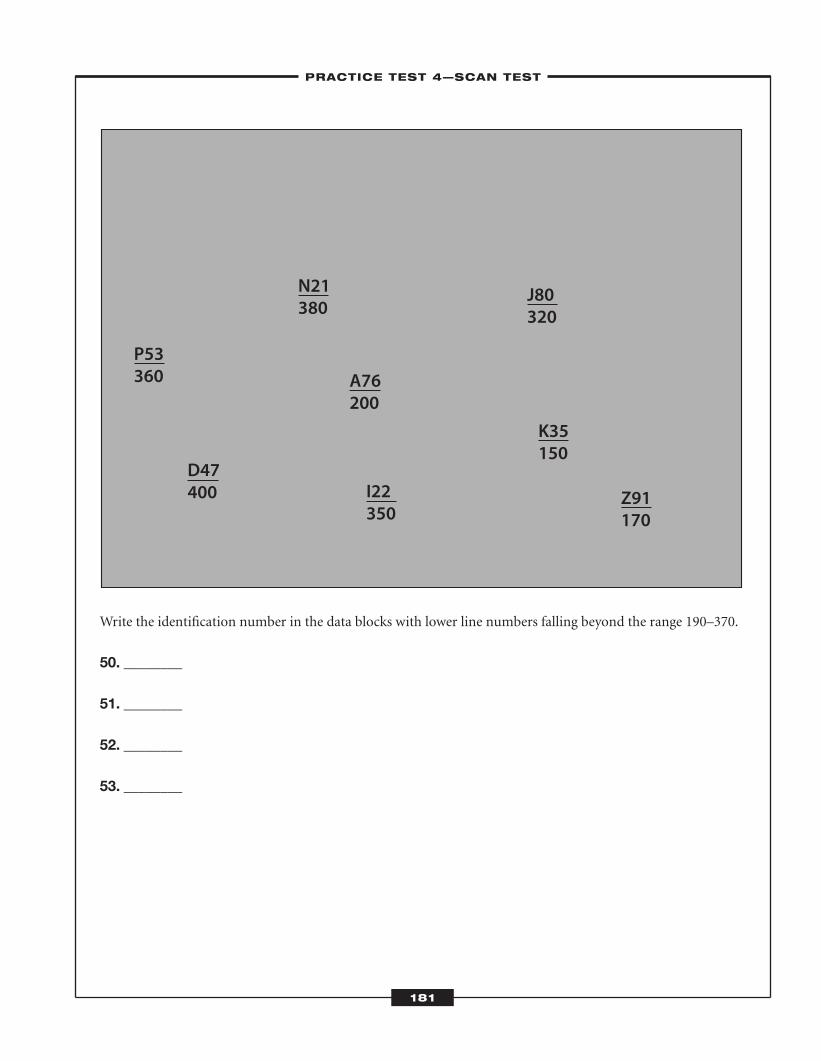
Write the identification number in the data blocks with lower line numbers falling beyond the range 190–370.
50. ________
51. ________
52. ________
53. ________
P53360
D47400
N21380
A76200
I22350
J80320
K35150
Z91170
–PRACTICE TEST 4—SCAN TEST–
181
ATC_2008b:Layout 1 11/24/08 1:17 PM Page 181
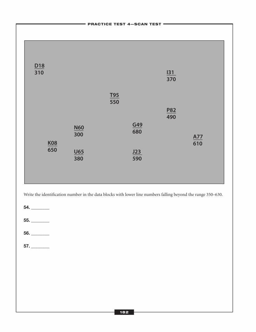
Write the identification number in the data blocks with lower line numbers falling beyond the range 350–630.
54. ________
55. ________
56. ________
57. ________
D18310
K08650
N60300
U65380
T95550
G49680
J23590
I31370
P82490
A77610
–PRACTICE TEST 4—SCAN TEST–
182
ATC_2008b:Layout 1 11/24/08 1:17 PM Page 182
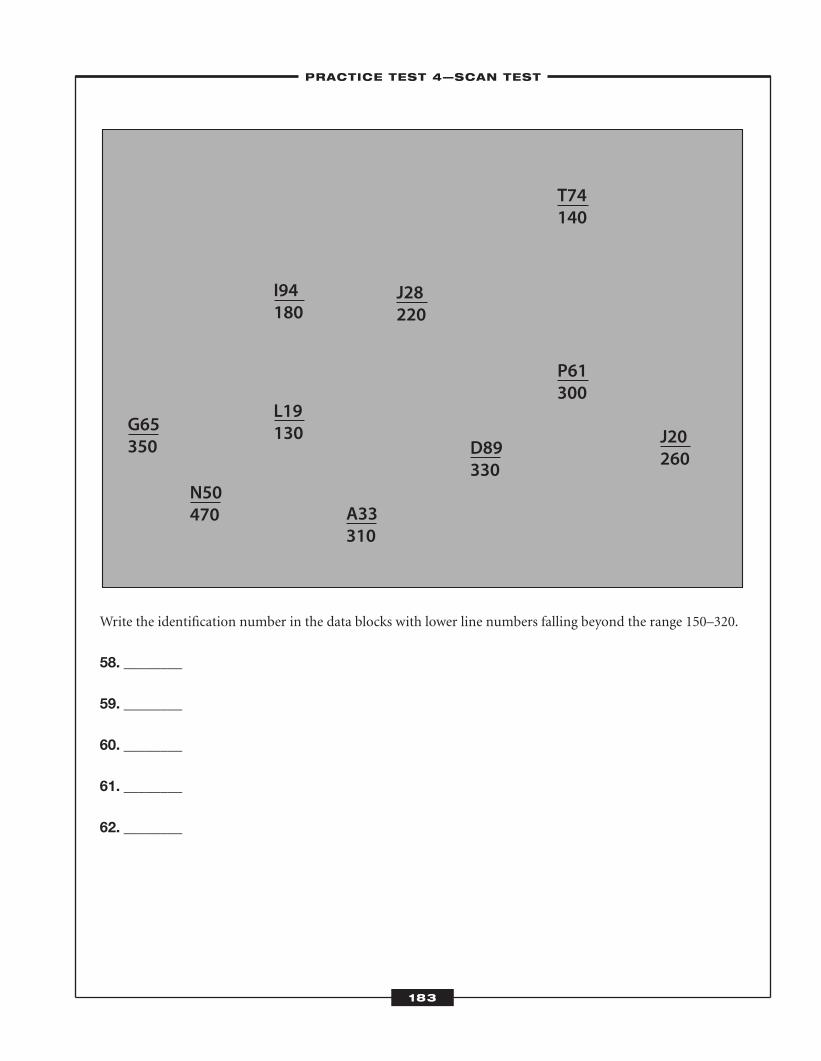
Write the identification number in the data blocks with lower line numbers falling beyond the range 150–320.
58. ________
59. ________
60. ________
61. ________
62. ________
G65350
N50470
I94180
L19130
A33310
J28220
D89330
T74140
P61300
J20260
–PRACTICE TEST 4—SCAN TEST–
183
ATC_2008b:Layout 1 11/24/08 1:17 PM Page 183
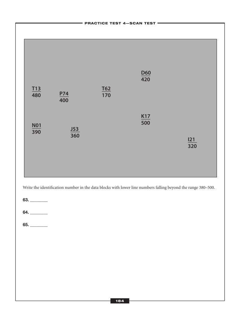
Write the identification number in the data blocks with lower line numbers falling beyond the range 380–500.
63. ________
64. ________
65. ________
T13480
N01390
P74400
J53360
T62170
D60420
K17500
I21320
–PRACTICE TEST 4—SCAN TEST–
184
ATC_2008b:Layout 1 11/24/08 1:17 PM Page 184
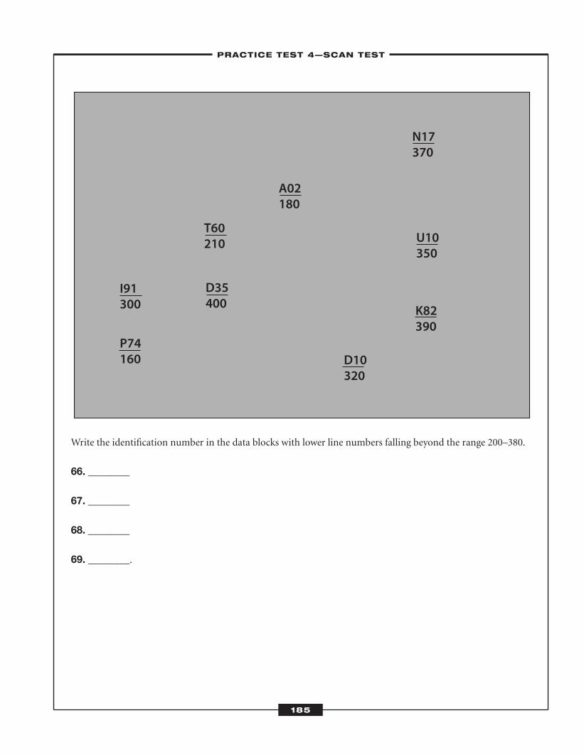
Write the identification number in the data blocks with lower line numbers falling beyond the range 200–380.
66. ________
67. ________
68. ________
69. ________.
I91300
N17370
P74160 D10
320
A02180
D35400
T60210
K82390
U10350
–PRACTICE TEST 4—SCAN TEST–
185
ATC_2008b:Layout 1 11/24/08 1:17 PM Page 185
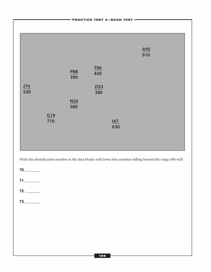
Write the identification number in the data blocks with lower line numbers falling beyond the range 400–620.
70. ________
71. ________
72. ________
73. ________
J74520
A95610
G19710
D53380
T06430
N26580
P88390
I47630
–PRACTICE TEST 4—SCAN TEST–
186
ATC_2008b:Layout 1 11/24/08 1:17 PM Page 186
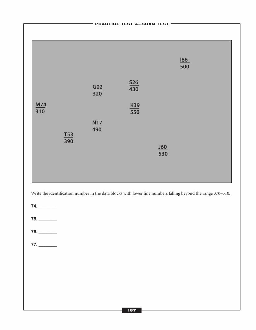
Write the identification number in the data blocks with lower line numbers falling beyond the range 370–510.
74. ________
75. ________
76. ________
77. ________
M74310
I86500
T53390
K39550
S26430
N17490
G02320
J60530
–PRACTICE TEST 4—SCAN TEST–
187
ATC_2008b:Layout 1 11/24/08 1:17 PM Page 187
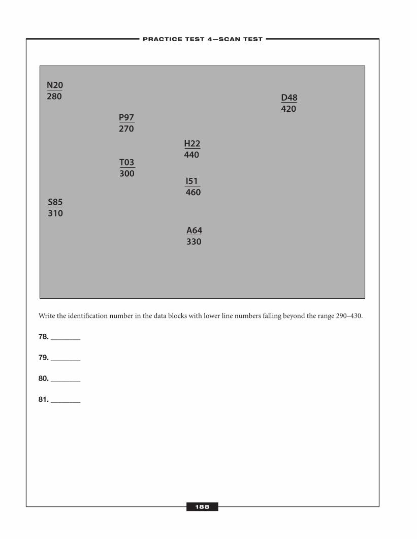
Write the identification number in the data blocks with lower line numbers falling beyond the range 290–430.
78. ________
79. ________
80. ________
81. ________
N20280 D48
420
S85310
I51460
H22440
P97270
T03300
A64330
–PRACTICE TEST 4—SCAN TEST–
188
ATC_2008b:Layout 1 11/24/08 1:17 PM Page 188
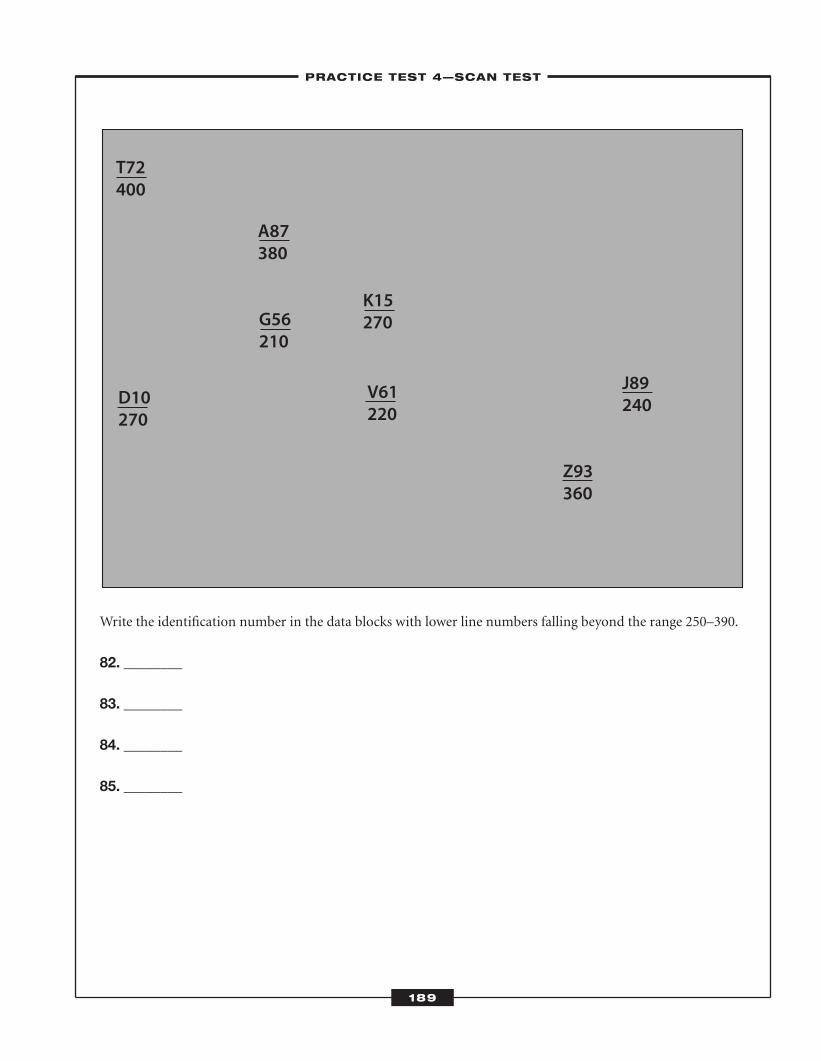
Write the identification number in the data blocks with lower line numbers falling beyond the range 250–390.
82. ________
83. ________
84. ________
85. ________
T72400
J89240D10
270V61220
K15270
A87380
G56210
Z93360
–PRACTICE TEST 4—SCAN TEST–
189
ATC_2008b:Layout 1 11/24/08 1:17 PM Page 189
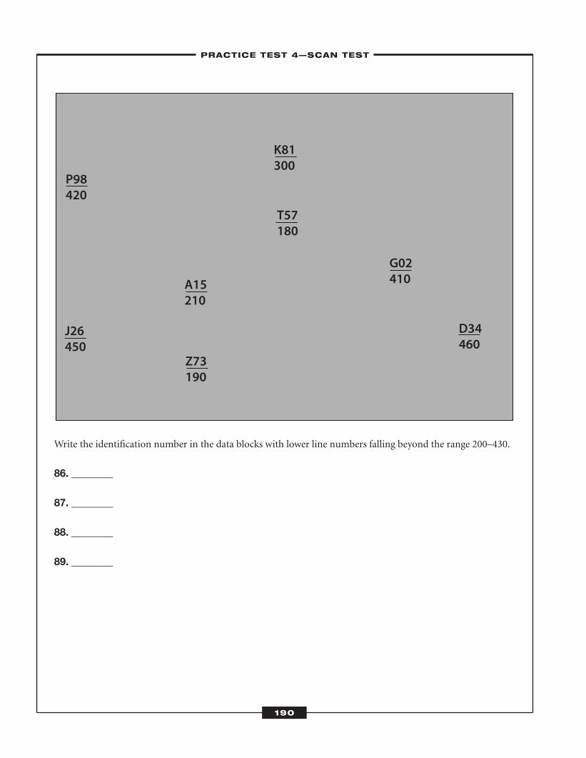
Write the identification number in the data blocks with lower line numbers falling beyond the range 200–430.
86. ________
87. ________
88. ________
89. ________
P98420
G02410
J26450
T57180
K81300
Z73190
A15210
D34460
–PRACTICE TEST 4—SCAN TEST–
190
ATC_2008b:Layout 1 11/24/08 1:17 PM Page 190
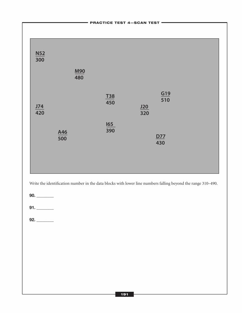
Write the identification number in the data blocks with lower line numbers falling beyond the range 310–490.
90. ________
91. ________
92. ________
N52300
G19510
J74420
T38450
M90480
J20320
I65390A46
500 D77430
–PRACTICE TEST 4—SCAN TEST–
191
ATC_2008b:Layout 1 11/24/08 1:17 PM Page 191
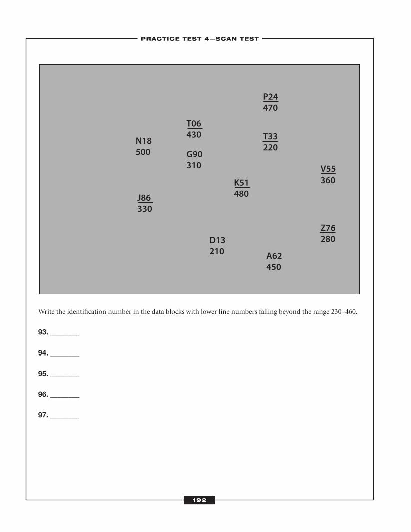
Write the identification number in the data blocks with lower line numbers falling beyond the range 230–460.
93. ________
94. ________
95. ________
96. ________
97. ________
N18500
P24470
J86330
G90310
T06430 T33
220
Z76280
V55360K51
480
D13210 A62
450
–PRACTICE TEST 4—SCAN TEST–
192
ATC_2008b:Layout 1 11/24/08 1:17 PM Page 192
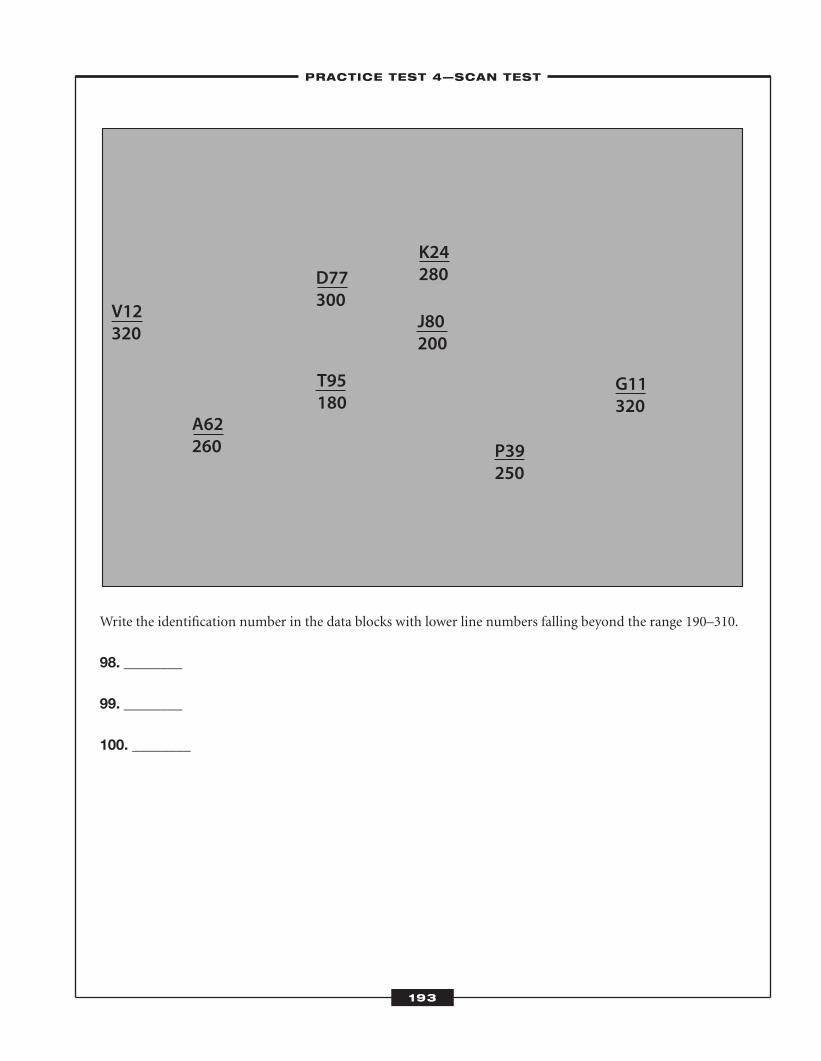
Write the identification number in the data blocks with lower line numbers falling beyond the range 190–310.
98. ________
99. ________
100. ________
V12320
K24280
A62260
T95180
D77300
J80200
P39250
G11320
–PRACTICE TEST 4—SCAN TEST–
193
ATC_2008b:Layout 1 11/24/08 1:17 PM Page 193
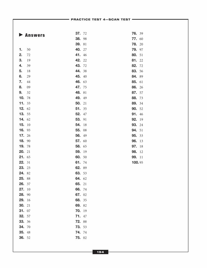
� Answers
1. 50
2. 72
3. 19
4. 39
5. 18
6. 29
7. 44
8. 09
9. 32
10. 7811. 3312. 6213. 5514. 6215. 1016. 9317. 26 18. 9019. 7820. 2121. 6522. 3123. 2324. 8225. 8826. 3727. 1028. 9029. 1630. 2131. 0732. 5733. 3634. 7035. 4836. 52
37. 7238. 9839. 8140. 2741. 4642. 2243. 7244. 3845. 4046. 6347. 7548. 8149. 4950. 2151. 3552. 4753. 9154. 1855. 0856. 4957. 6058. 6559. 1960. 5061. 7462. 8963. 5364. 6265. 2166. 7467. 0268. 3569. 8270. 1971. 4772. 8873. 5374. 7475. 02
76. 3977. 6078. 2079. 9780. 5181. 2282. 7283. 5684. 8985. 6186. 2687. 5788. 7389. 3490. 5291. 4692. 1993. 2494. 5195. 3396. 1397. 1898. 1299. 11100. 95
–PRACTICE TEST 4—SCAN TEST–
194
ATC_2008b:Layout 1 11/24/08 1:17 PM Page 194
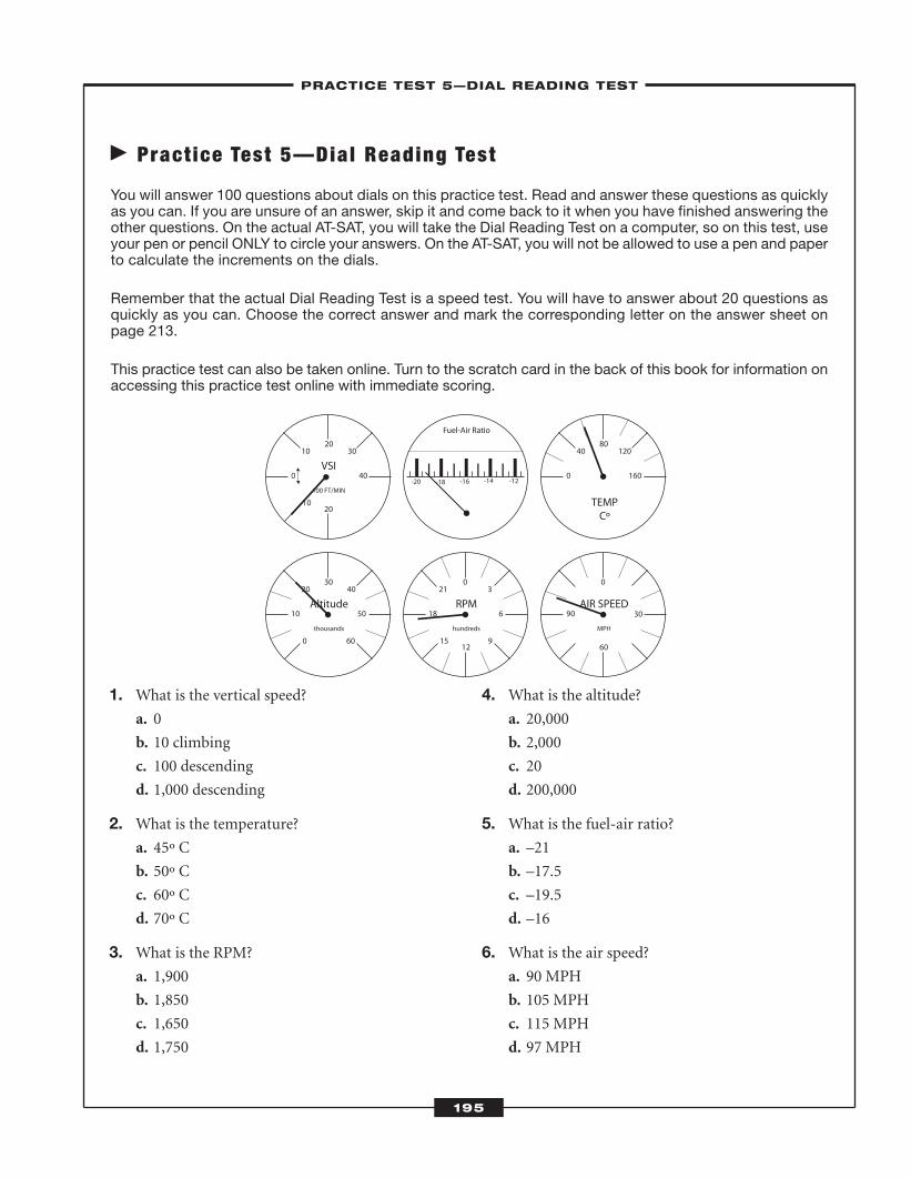
� Pract ice Test 5—Dial Reading Test
You will answer 100 questions about dials on this practice test. Read and answer these questions as quicklyas you can. If you are unsure of an answer, skip it and come back to it when you have finished answering theother questions. On the actual AT-SAT, you will take the Dial Reading Test on a computer, so on this test, useyour pen or pencil ONLY to circle your answers. On the AT-SAT, you will not be allowed to use a pen and paperto calculate the increments on the dials.
Remember that the actual Dial Reading Test is a speed test. You will have to answer about 20 questions asquickly as you can. Choose the correct answer and mark the corresponding letter on the answer sheet onpage 213.
This practice test can also be taken online. Turn to the scratch card in the back of this book for information onaccessing this practice test online with immediate scoring.
10
0 40
10 3020
20
VSI
100 FT/MIN
0
10 50
20
60
4030
Altitude
thousands
0 160
40 12080
TEMPCº
15
18 6
21
9
30
12
RPM
hundreds
90 30
0
60
AIR SPEED
MPH
-12-14-16-18-20
Fuel-Air Ratio
–PRACTICE TEST 5—DIAL READING TEST–
195
1. What is the vertical speed?a. 0
b. 10 climbing
c. 100 descending
d. 1,000 descending
2. What is the temperature?a. 45º C
b. 50º C
c. 60º C
d. 70º C
3. What is the RPM?a. 1,900
b. 1,850
c. 1,650
d. 1,750
4. What is the altitude?a. 20,000
b. 2,000
c. 20
d. 200,000
5. What is the fuel-air ratio?a. –21
b. –17.5
c. –19.5
d. –16
6. What is the air speed?a. 90 MPH
b. 105 MPH
c. 115 MPH
d. 97 MPH
ATC_2008b:Layout 1 11/24/08 1:17 PM Page 195
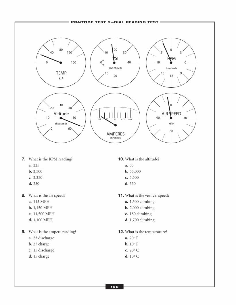
7. What is the RPM reading?a. 225
b. 2,500
c. 2,250
d. 250
8. What is the air speed?a. 115 MPH
b. 1,150 MPH
c. 11,500 MPH
d. 1,100 MPH
9. What is the ampere reading?a. 25 discharge
b. 25 charge
c. 15 discharge
d. 15 charge
10.What is the altitude?a. 55
b. 55,000
c. 5,500
d. 550
11.What is the vertical speed?a. 1,500 climbing
b. 2,000 climbing
c. 180 climbing
d. 1,700 climbing
12.What is the temperature?a. 20º F
b. 10º F
c. 20º C
d. 10º C
10
0 40
10 3020
20
VSI
100 FT/MIN
0
10 50
20
60
4030
Altitude
thousands
0 160
40 12080
TEMPCº
15
18 6
21
9
30
12
RPM
hundreds
90 30
0
60
AIR SPEED
MPH
-30 -15 0 +15 +30
AMPERESmAmpes
–PRACTICE TEST 5—DIAL READING TEST–
196
ATC_2008b:Layout 1 11/24/08 1:17 PM Page 196
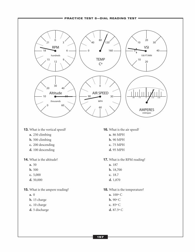
13.What is the vertical speed?a. 250 climbing
b. 500 climbing
c. 200 descending
d. 100 descending
14.What is the altitude?a. 50
b. 500
c. 5,000
d. 50,000
15.What is the ampere reading?a. 0
b. 15 charge
c. 10 charge
d. 5 discharge
16.What is the air speed?a. 86 MPH
b. 90 MPH
c. 75 MPH
d. 95 MPH
17.What is the RPM reading?a. 187
b. 18,700
c. 18.7
d. 1,870
18.What is the temperature?a. 100º C
b. 90º C
c. 85º C
d. 87.5º C
10
0 40
10 3020
20
VSI
100 FT/MIN
0
10 50
20
60
4030
Altitude
thousands
0 160
40 12080
TEMPCº
15
18 6
21
9
30
12
RPM
hundreds
90 30
0
60
AIR SPEED
MPH
-30 -15 0 +15 +30
AMPERESmAmpes
–PRACTICE TEST 5—DIAL READING TEST–
197
ATC_2008b:Layout 1 11/24/08 1:17 PM Page 197
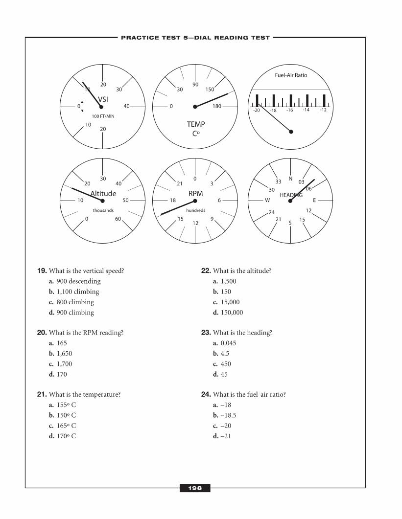
19.What is the vertical speed?a. 900 descending
b. 1,100 climbing
c. 800 climbing
d. 900 climbing
20.What is the RPM reading?a. 165
b. 1,650
c. 1,700
d. 170
21.What is the temperature?a. 155º C
b. 150º C
c. 165º C
d. 170º C
22.What is the altitude?a. 1,500
b. 150
c. 15,000
d. 150,000
23.What is the heading?a. 0.045
b. 4.5
c. 450
d. 45
24.What is the fuel-air ratio?a. –18
b. –18.5
c. –20
d. –21
10
0 40
10 3020
20
VSI
100 FT/MIN
0
10 50
20
60
4030
Altitude
thousands
0 180
30 15090
TEMPCº
15
18 6
21
9
30
12
RPM
hundreds
W E
N
S
HEADING
3330
2421 15
12
0603
-12-14-16-18-20
Fuel-Air Ratio
–PRACTICE TEST 5—DIAL READING TEST–
198
ATC_2008b:Layout 1 11/24/08 1:17 PM Page 198
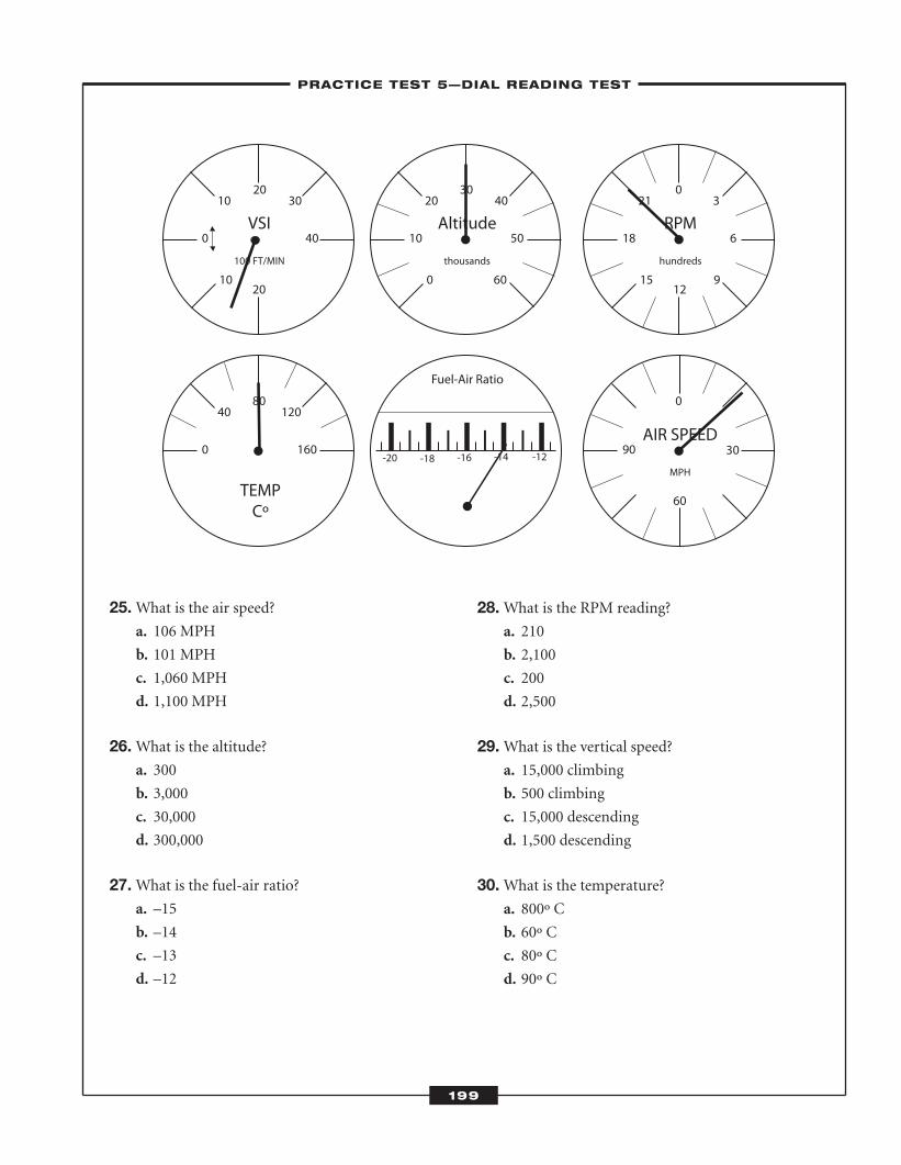
25.What is the air speed?a. 106 MPH
b. 101 MPH
c. 1,060 MPH
d. 1,100 MPH
26.What is the altitude?a. 300
b. 3,000
c. 30,000
d. 300,000
27.What is the fuel-air ratio?a. –15
b. –14
c. –13
d. –12
28.What is the RPM reading?a. 210
b. 2,100
c. 200
d. 2,500
29.What is the vertical speed?a. 15,000 climbing
b. 500 climbing
c. 15,000 descending
d. 1,500 descending
30.What is the temperature?a. 800º C
b. 60º C
c. 80º C
d. 90º C
10
0 40
10 3020
20
VSI
100 FT/MIN
0
10 50
20
60
4030
Altitude
thousands
0 160
40 12080
TEMPCº
15
18 6
21
9
30
12
RPM
hundreds
-12-14-16-18-20
Fuel-Air Ratio
90 30
0
60
AIR SPEED
MPH
–PRACTICE TEST 5—DIAL READING TEST–
199
ATC_2008b:Layout 1 11/24/08 1:17 PM Page 199
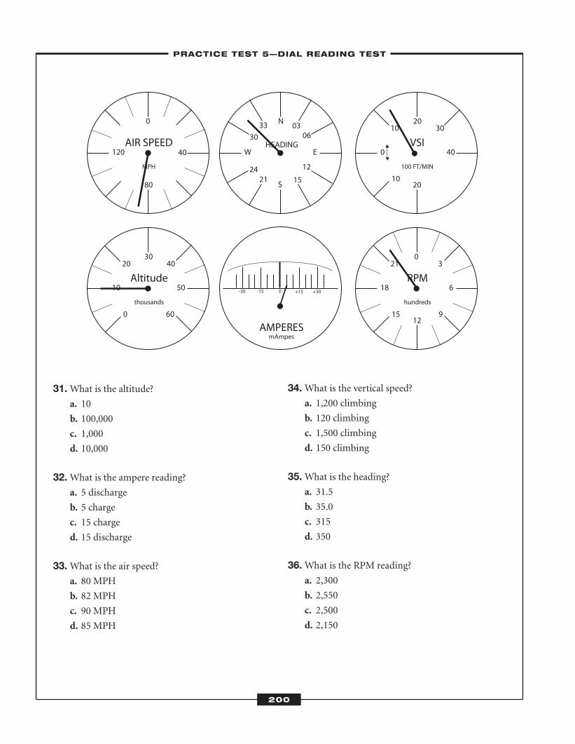
31.What is the altitude?a. 10
b. 100,000
c. 1,000
d. 10,000
32.What is the ampere reading?a. 5 discharge
b. 5 charge
c. 15 charge
d. 15 discharge
33.What is the air speed?a. 80 MPH
b. 82 MPH
c. 90 MPH
d. 85 MPH
34.What is the vertical speed?a. 1,200 climbing
b. 120 climbing
c. 1,500 climbing
d. 150 climbing
35.What is the heading?a. 31.5
b. 35.0
c. 315
d. 350
36.What is the RPM reading?a. 2,300
b. 2,550
c. 2,500
d. 2,150
10
0 40
10 3020
20
VSI
100 FT/MIN
0
10 50
20
60
4030
Altitude
thousands
15
18 6
21
9
30
12
RPM
hundreds
W E
N
S
HEADING
3330
2421 15
12
0603
-30 -15 0 +15 +30
AMPERESmAmpes
120 40
0
80
AIR SPEED
MPH
–PRACTICE TEST 5—DIAL READING TEST–
200
ATC_2008b:Layout 1 11/24/08 1:17 PM Page 200
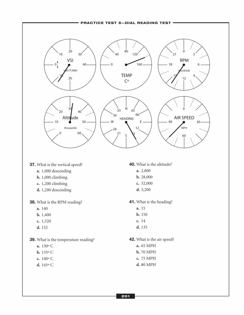
37.What is the vertical speed?a. 1,000 descending
b. 1,000 climbing
c. 1,200 climbing
d. 1,200 descending
38.What is the RPM reading?a. 140
b. 1,400
c. 1,520
d. 152
39.What is the temperature reading?a. 130º C
b. 135º C
c. 140º C
d. 145º C
40.What is the altitude?a. 2,800
b. 28,000
c. 32,000
d. 3,200
41.What is the heading?a. 15
b. 150
c. 14
d. 135
42.What is the air speed?a. 65 MPH
b. 70 MPH
c. 75 MPH
d. 80 MPH
10
0 40
10 3020
20
VSI
100 FT/MIN
0
10 50
20
60
4030
Altitude
thousands
15
18 6
21
9
30
12
RPM
hundreds
W E
N
S
HEADING
3330
2421 15
12
0603
90 30
0
60
AIR SPEED
MPH
0 160
40 12080
TEMPCº
–PRACTICE TEST 5—DIAL READING TEST–
201
ATC_2008b:Layout 1 11/24/08 1:17 PM Page 201
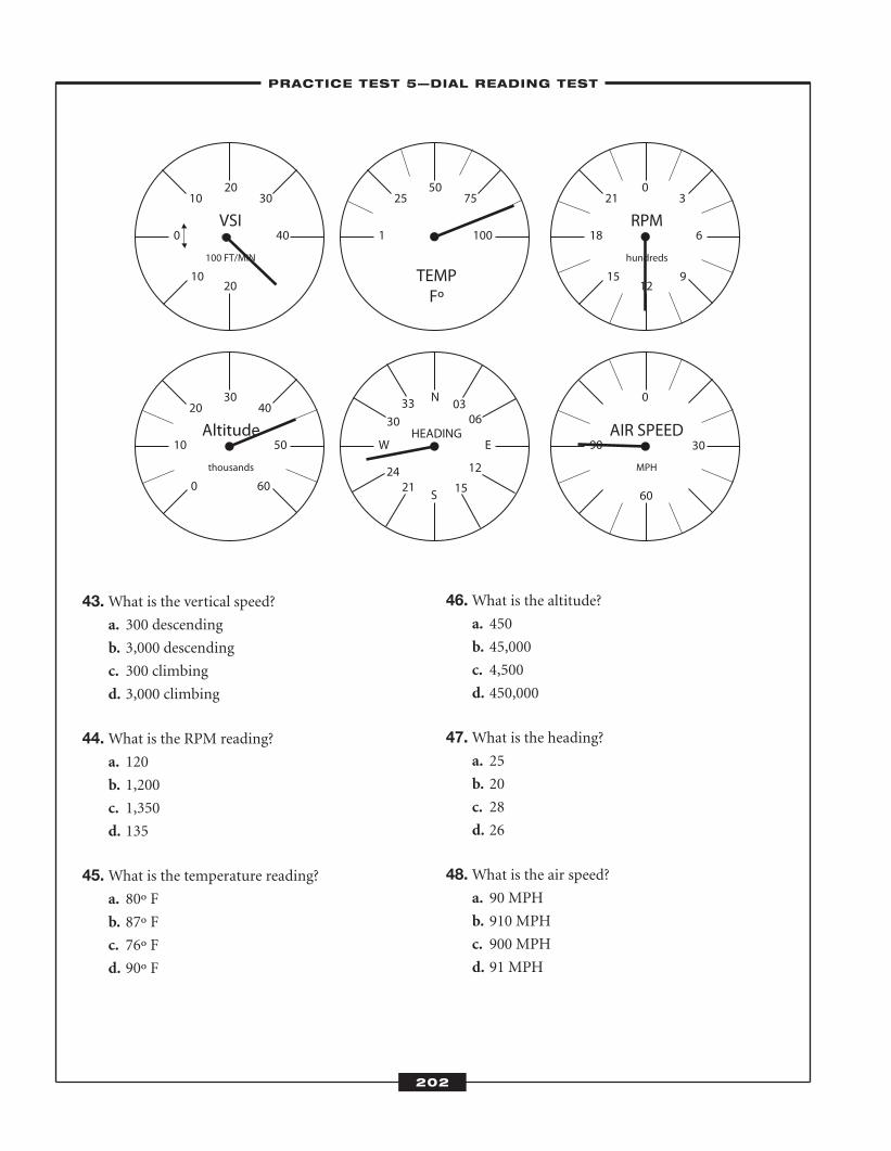
43.What is the vertical speed?a. 300 descending
b. 3,000 descending
c. 300 climbing
d. 3,000 climbing
44.What is the RPM reading?a. 120
b. 1,200
c. 1,350
d. 135
45.What is the temperature reading?a. 80º F
b. 87º F
c. 76º F
d. 90º F
46.What is the altitude?a. 450
b. 45,000
c. 4,500
d. 450,000
47.What is the heading?a. 25
b. 20
c. 28
d. 26
48.What is the air speed?a. 90 MPH
b. 910 MPH
c. 900 MPH
d. 91 MPH
10
0 40
10 3020
20
VSI
100 FT/MIN
0
10 50
20
60
4030
Altitude
thousands
W E
N
S
HEADING
3330
2421 15
12
0603
90 30
0
60
AIR SPEED
MPH
15
18 6
21
9
30
12
RPM
hundreds
1 100
25 7550
TEMPFº
–PRACTICE TEST 5—DIAL READING TEST–
202
ATC_2008b:Layout 1 11/24/08 1:17 PM Page 202
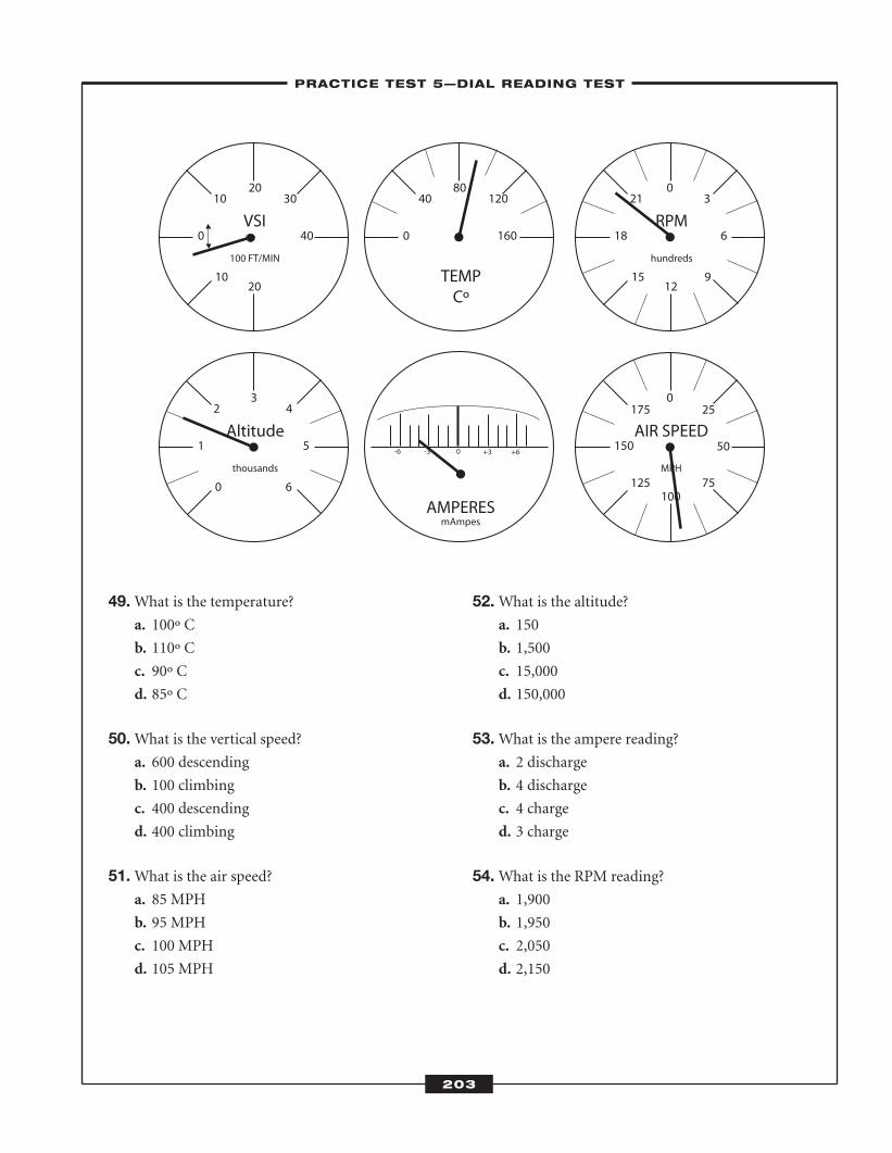
49.What is the temperature?a. 100º C
b. 110º C
c. 90º C
d. 85º C
50.What is the vertical speed?a. 600 descending
b. 100 climbing
c. 400 descending
d. 400 climbing
51.What is the air speed?a. 85 MPH
b. 95 MPH
c. 100 MPH
d. 105 MPH
52.What is the altitude?a. 150
b. 1,500
c. 15,000
d. 150,000
53.What is the ampere reading?a. 2 discharge
b. 4 discharge
c. 4 charge
d. 3 charge
54.What is the RPM reading?a. 1,900
b. 1,950
c. 2,050
d. 2,150
10
0 40
10 3020
20
VSI
100 FT/MIN
0
1 5
2
6
43
Altitude
thousands
15
18 6
21
9
30
12
RPM
hundreds
150 50
0175 25
125 75100
AIR SPEED
MPH
0 160
40 12080
TEMPCº
-6 -3 0 +3 +6
AMPERESmAmpes
–PRACTICE TEST 5—DIAL READING TEST–
203
ATC_2008b:Layout 1 11/24/08 1:17 PM Page 203
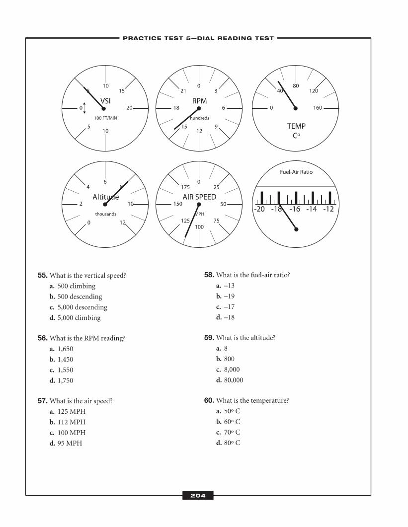
55.What is the vertical speed?a. 500 climbing
b. 500 descending
c. 5,000 descending
d. 5,000 climbing
56.What is the RPM reading?a. 1,650
b. 1,450
c. 1,550
d. 1,750
57.What is the air speed?a. 125 MPH
b. 112 MPH
c. 100 MPH
d. 95 MPH
58.What is the fuel-air ratio?a. –13
b. –19
c. –17
d. –18
59.What is the altitude?a. 8
b. 800
c. 8,000
d. 80,000
60.What is the temperature?a. 50º C
b. 60º C
c. 70º C
d. 80º C
5
0 20
5 1510
10
VSI
100 FT/MIN
0
2 10
4
12
86
Altitude
thousands
15
18 6
21
9
30
12
RPM
hundreds
150 50
0175 25
125 75100
AIR SPEED
MPH
0 160
40 12080
TEMPCº
-12-14-16-18-20
Fuel-Air Ratio
–PRACTICE TEST 5—DIAL READING TEST–
204
ATC_2008b:Layout 1 11/24/08 1:17 PM Page 204
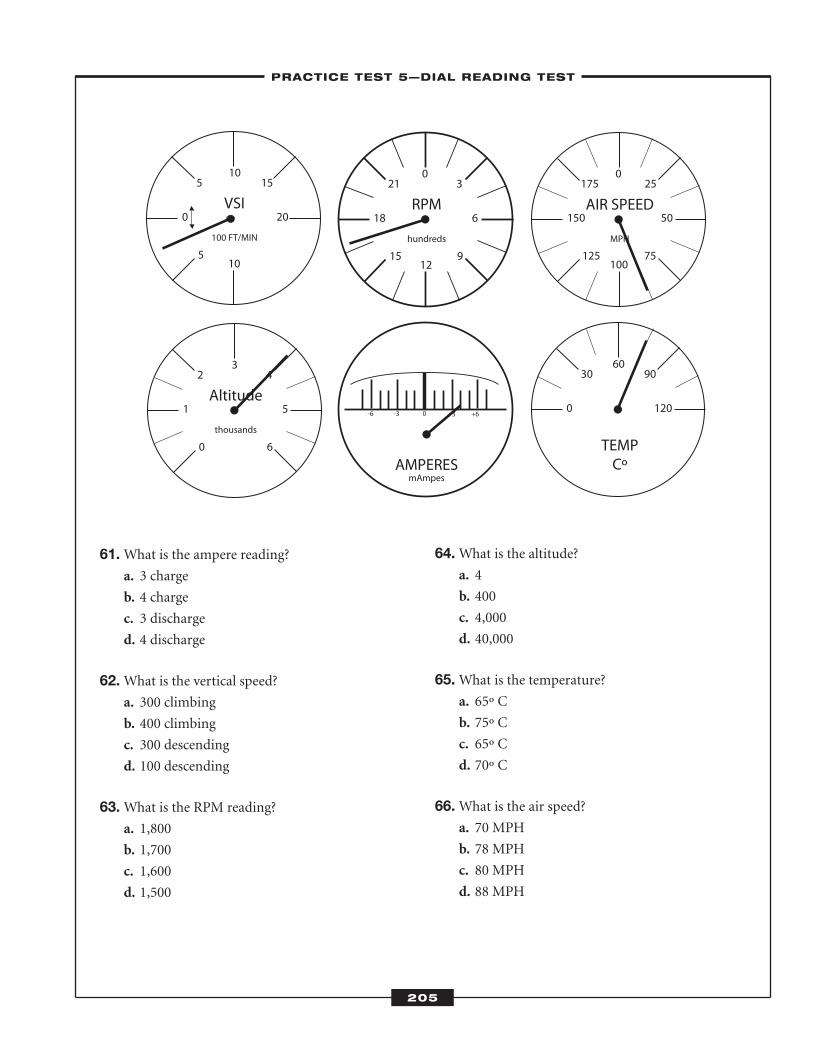
61.What is the ampere reading?a. 3 charge
b. 4 charge
c. 3 discharge
d. 4 discharge
62.What is the vertical speed?a. 300 climbing
b. 400 climbing
c. 300 descending
d. 100 descending
63.What is the RPM reading?a. 1,800
b. 1,700
c. 1,600
d. 1,500
64.What is the altitude?a. 4
b. 400
c. 4,000
d. 40,000
65.What is the temperature?a. 65º C
b. 75º C
c. 65º C
d. 70º C
66.What is the air speed?a. 70 MPH
b. 78 MPH
c. 80 MPH
d. 88 MPH
5
0 20
5 1510
10
VSI
100 FT/MIN
15
18 6
21
9
30
12
RPM
hundreds
0
1 5
2
6
43
Altitude
thousands
-6 -3 0 +3 +6
AMPERESmAmpes
0 120
30 9060
TEMPCº
AIR SPEED
MPH
125
175
75
25
150 50
0
100
–PRACTICE TEST 5—DIAL READING TEST–
205
ATC_2008b:Layout 1 11/24/08 1:17 PM Page 205
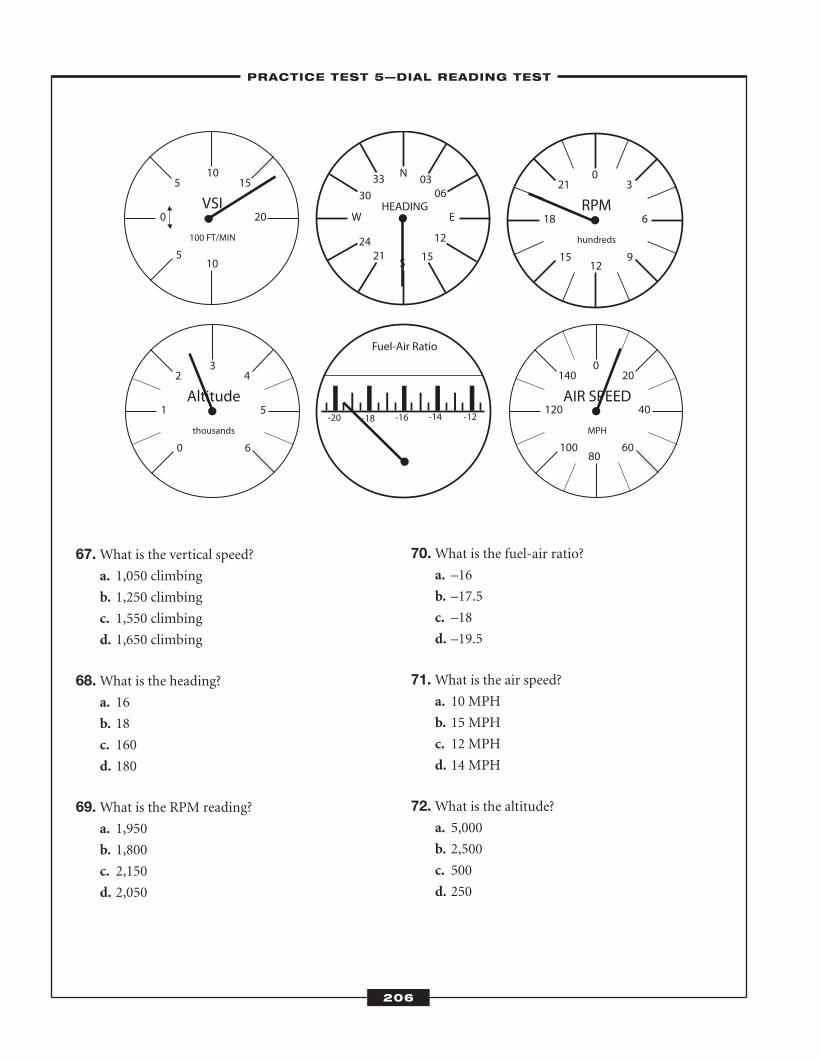
67.What is the vertical speed?a. 1,050 climbing
b. 1,250 climbing
c. 1,550 climbing
d. 1,650 climbing
68.What is the heading?a. 16
b. 18
c. 160
d. 180
69.What is the RPM reading?a. 1,950
b. 1,800
c. 2,150
d. 2,050
70.What is the fuel-air ratio?a. –16
b. –17.5
c. –18
d. –19.5
71.What is the air speed?a. 10 MPH
b. 15 MPH
c. 12 MPH
d. 14 MPH
72.What is the altitude?a. 5,000
b. 2,500
c. 500
d. 250
5
0 20
5 1510
10
VSI
100 FT/MIN
15
18 6
21
9
30
12
RPM
hundreds
AIR SPEED
MPH
100
140
60
20
120 40
0
80
-12-14-16-18-20
Fuel-Air Ratio
0
1 5
2
6
43
Altitude
thousands
W E
N
S
HEADING
3330
2421 15
12
0603
–PRACTICE TEST 5—DIAL READING TEST–
206
ATC_2008b:Layout 1 11/24/08 1:17 PM Page 206
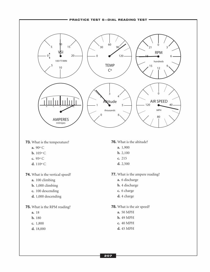
73.What is the temperature?a. 90º C
b. 105º C
c. 95º C
d. 110º C
74.What is the vertical speed?a. 100 climbing
b. 1,000 climbing
c. 100 descending
d. 1,000 descending
75.What is the RPM reading?a. 18
b. 180
c. 1,800
d. 18,000
76.What is the altitude?a. 1,900
b. 2,100
c. 215
d. 2,500
77.What is the ampere reading?a. 6 discharge
b. 4 discharge
c. 6 charge
d. 4 charge
78.What is the air speed?a. 50 MPH
b. 49 MPH
c. 40 MPH
d. 45 MPH
5
0 20
5 1510
10
VSI
100 FT/MIN
0
1 5
2
6
43
Altitude
thousands
0 120
30 9060
TEMPCº
AIR SPEED
MPH
120 40
0
80
15
18 6
21
9
30
12
RPM
hundreds
-6 -3 0 +3 +6
AMPERESmAmpes
–PRACTICE TEST 5—DIAL READING TEST–
207
ATC_2008b:Layout 1 11/24/08 1:17 PM Page 207
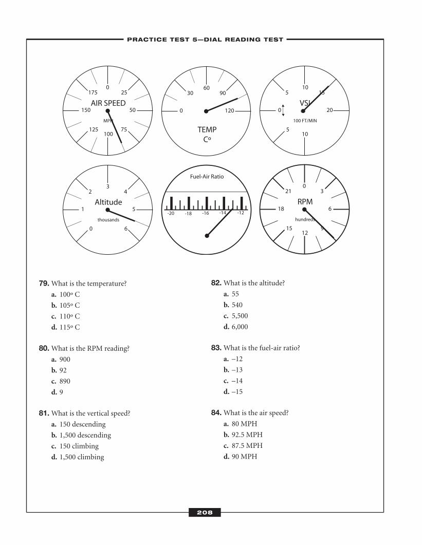
79.What is the temperature?a. 100º C
b. 105º C
c. 110º C
d. 115º C
80.What is the RPM reading?a. 900
b. 92
c. 890
d. 9
81.What is the vertical speed?a. 150 descending
b. 1,500 descending
c. 150 climbing
d. 1,500 climbing
82.What is the altitude?a. 55
b. 540
c. 5,500
d. 6,000
83.What is the fuel-air ratio?a. –12
b. –13
c. –14
d. –15
84.What is the air speed?a. 80 MPH
b. 92.5 MPH
c. 87.5 MPH
d. 90 MPH
5
0 20
5 1510
10
VSI
100 FT/MIN
0
1 5
2
6
43
Altitude
thousands
0 120
30 9060
TEMPCº
AIR SPEED
MPH
125
175
75
25
150 50
0
100
-12-14-16-18-20
Fuel-Air Ratio
15
18 6
21
9
30
12
RPM
hundreds
–PRACTICE TEST 5—DIAL READING TEST–
208
ATC_2008b:Layout 1 11/24/08 1:17 PM Page 208
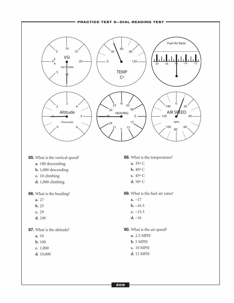
85.What is the vertical speed?a. 100 descending
b. 1,000 descending
c. 10 climbing
d. 1,000 climbing
86.What is the heading?a. 27
b. 25
c. 29
d. 240
87.What is the altitude?a. 10
b. 100
c. 1,000
d. 10,000
88.What is the temperature?a. 35º C
b. 40º C
c. 45º C
d. 50º C
89.What is the fuel-air ratio?a. –17
b. –16.5
c. –15.5
d. –16
90.What is the air speed?a. 2.5 MPH
b. 5 MPH
c. 10 MPH
d. 15 MPH
5
0 20
5 1510
10
VSI
100 FT/MIN
0
1 5
2
6
43
Altitude
thousands
0 120
30 9060
TEMPCº
AIR SPEED
MPH
100
140
60
20
120 40
0
80
-12-14-16-18-20
Fuel-Air Ratio
W E
N
S
HEADING
3330
2421 15
12
0603
–PRACTICE TEST 5—DIAL READING TEST–
209
ATC_2008b:Layout 1 11/24/08 1:17 PM Page 209
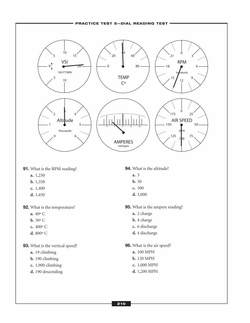
91.What is the RPM reading?a. 1,250
b. 1,350
c. 1,400
d. 1,450
92.What is the temperature?a. 40º C
b. 30º C
c. 400º C
d. 800º C
93.What is the vertical speed?a. 19 climbing
b. 190 climbing
c. 1,900 climbing
d. 190 descending
94.What is the altitude?a. 3
b. 30
c. 300
d. 3,000
95.What is the ampere reading?a. 2 charge
b. 4 charge
c. 6 discharge
d. 4 discharge
96.What is the air speed?a. 100 MPH
b. 120 MPH
c. 1,000 MPH
d. 1,200 MPH
5
0 20
5 1510
10
VSI
100 FT/MIN
0
1 5
2
6
43
Altitude
thousands
0 80
20 6040
TEMPCº
-6 -3 0 +3 +6
AMPERESmAmpes
15
18 6
21
9
30
12
RPM
hundreds
AIR SPEED
MPH
125
175
75
25
150 50
0
100
–PRACTICE TEST 5—DIAL READING TEST–
210
ATC_2008b:Layout 1 11/24/08 1:17 PM Page 210
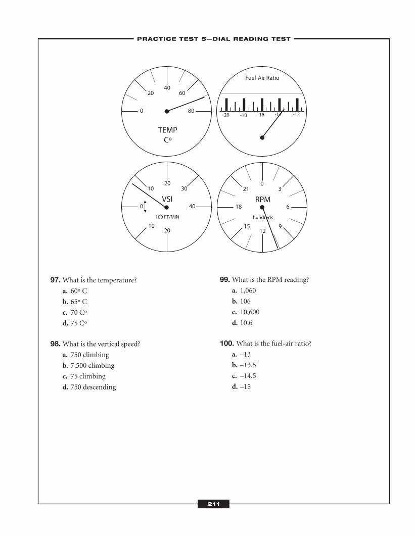
97.What is the temperature?a. 60º C
b. 65º C
c. 70 Cº
d. 75 Cº
98.What is the vertical speed?a. 750 climbing
b. 7,500 climbing
c. 75 climbing
d. 750 descending
99.What is the RPM reading?a. 1,060
b. 106
c. 10,600
d. 10.6
100. What is the fuel-air ratio?a. –13
b. –13.5
c. –14.5
d. –15
15
18 6
21
9
30
12
RPM
hundreds
10
0 40
10 3020
20
VSI
100 FT/MIN
0 80
20 6040
TEMPCº
-12-14-16-18-20
Fuel-Air Ratio
–PRACTICE TEST 5—DIAL READING TEST–
211
ATC_2008b:Layout 1 11/24/08 1:17 PM Page 211

ATC_2008b:Layout 1 11/24/08 1:17 PM Page 212

Practice Test 5—Dial Reading Test
–LEARNINGEXPRESS ANSWER SHEET–
213
1. a b c d
2. a b c d
3. a b c d
4. a b c d
5. a b c d
6. a b c d
7. a b c d
8. a b c d
9. a b c d
10. a b c d
11. a b c d
12. a b c d
13. a b c d
14. a b c d
15. a b c d
16. a b c d
17. a b c d
18. a b c d
19. a b c d
20. a b c d
21. a b c d
22. a b c d
23. a b c d
24. a b c d
25. a b c d
26. a b c d
27. a b c d
28. a b c d
29. a b c d
30. a b c d
31. a b c d
32. a b c d
33. a b c d
34. a b c d
35. a b c d
36. a b c d
37. a b c d
38. a b c d
39. a b c d
40. a b c d
41. a b c d
42. a b c d
43. a b c d
44. a b c d
45. a b c d
46. a b c d
47. a b c d
48. a b c d
49. a b c d
50. a b c d
51. a b c d
52. a b c d
53. a b c d
54. a b c d
55. a b c d
56. a b c d
57. a b c d
58. a b c d
59. a b c d
60. a b c d
61. a b c d
62. a b c d
63. a b c d
64. a b c d
65. a b c d
66. a b c d
67. a b c d
68. a b c d
69. a b c d
70. a b c d
71. a b c d
72. a b c d
73. a b c d
74. a b c d
75. a b c d
76. a b c d
77. a b c d
78. a b c d
79. a b c d
80. a b c d
81. a b c d
82. a b c d
83. a b c d
84. a b c d
85. a b c d
86. a b c d
87. a b c d
88. a b c d
89. a b c d
90. a b c d
91. a b c d
92. a b c d
93. a b c d
94. a b c d
95. a b c d
96. a b c d
97. a b c d
98. a b c d
99. a b c d
100. a b c d
ATC_2008b:Layout 1 11/24/08 1:18 PM Page 213
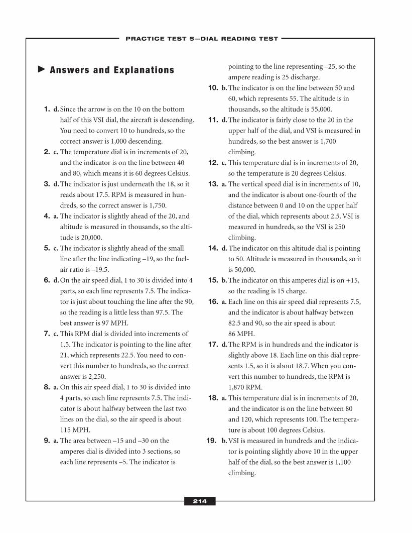
� Answers and Explanat ions
1. d.Since the arrow is on the 10 on the bottomhalf of this VSI dial, the aircraft is descending.
You need to convert 10 to hundreds, so the
correct answer is 1,000 descending.
2. c. The temperature dial is in increments of 20,and the indicator is on the line between 40
and 80, which means it is 60 degrees Celsius.
3. d.The indicator is just underneath the 18, so itreads about 17.5. RPM is measured in hun-
dreds, so the correct answer is 1,750.
4. a. The indicator is slightly ahead of the 20, andaltitude is measured in thousands, so the alti-
tude is 20,000.
5. c. The indicator is slightly ahead of the smallline after the line indicating –19, so the fuel-
air ratio is –19.5.
6. d.On the air speed dial, 1 to 30 is divided into 4parts, so each line represents 7.5. The indica-
tor is just about touching the line after the 90,
so the reading is a little less than 97.5. The
best answer is 97 MPH.
7. c. This RPM dial is divided into increments of1.5. The indicator is pointing to the line after
21, which represents 22.5. You need to con-
vert this number to hundreds, so the correct
answer is 2,250.
8. a.On this air speed dial, 1 to 30 is divided into4 parts, so each line represents 7.5. The indi-
cator is about halfway between the last two
lines on the dial, so the air speed is about
115 MPH.
9. a. The area between –15 and –30 on theamperes dial is divided into 3 sections, so
each line represents –5. The indicator is
pointing to the line representing –25, so the
ampere reading is 25 discharge.
10. b.The indicator is on the line between 50 and60, which represents 55. The altitude is in
thousands, so the altitude is 55,000.
11. d.The indicator is fairly close to the 20 in theupper half of the dial, and VSI is measured in
hundreds, so the best answer is 1,700
climbing.
12. c. This temperature dial is in increments of 20,so the temperature is 20 degrees Celsius.
13. a. The vertical speed dial is in increments of 10,and the indicator is about one-fourth of the
distance between 0 and 10 on the upper half
of the dial, which represents about 2.5. VSI is
measured in hundreds, so the VSI is 250
climbing.
14. d. The indicator on this altitude dial is pointingto 50. Altitude is measured in thousands, so it
is 50,000.
15. b.The indicator on this amperes dial is on +15,so the reading is 15 charge.
16. a. Each line on this air speed dial represents 7.5,and the indicator is about halfway between
82.5 and 90, so the air speed is about
86 MPH.
17. d.The RPM is in hundreds and the indicator isslightly above 18. Each line on this dial repre-
sents 1.5, so it is about 18.7. When you con-
vert this number to hundreds, the RPM is
1,870 RPM.
18. a. This temperature dial is in increments of 20,and the indicator is on the line between 80
and 120, which represents 100. The tempera-
ture is about 100 degrees Celsius.
19. b.VSI is measured in hundreds and the indica-tor is pointing slightly above 10 in the upper
half of the dial, so the best answer is 1,100
climbing.
-–PRACTICE TEST 5—DIAL READING TEST–
214
ATC_2008b:Layout 1 11/24/08 1:18 PM Page 214
20. b.RPM is measured in hundreds and each lineon this dial represents 1.5. The indicator is
pointing to the line between 15 and 18, so the
answer is 16.5. When you convert this num-
ber to hundreds, the answer is 1,650.
21. c. This temperature dial is in increments of 15.The indicator is pointing to the line between
150 and 180, so the temperature is 165
degrees Celsius.
22. c. Altitude is measured in thousands and theindicator is pointing to 15, so the correct
answer is 15,000.
23. b.Each line on the heading dial represents 3,and the indicator is pointing to an area
between 3 and 6, so the correct answer is 4.5.
24. c. Each line on this fuel-air ratio dial represents–0.5. The indicator is pointing to –20, which
is the fuel-air ratio for this aircraft.
25. a. Each line on the air speed dial represents 7.5,and the indicator is pointing slightly ahead of
the line representing 105, so the best answer
is 106 MPH.
26. c. Altitude is measured in thousands, and theindicator is pointing to 30, so the correct
answer is 30,000.
27. b.Each line on this fuel-air ratio represents –0.5, and the indicator is pointing to –14, so
this is the fuel-air ratio.
28. b.RPM is measured in hundreds and the indi-cator is pointing to 21, so the correct answer
is 2,100.
29. d.VSI is measured in hundreds and the indica-tor is pointing to 15 on the bottom half of the
dial, so the answer is 1,500 descending.
30. c. This temperature dial is in increments of 20.The indicator is pointing to 80, so the tem-
perature is 80 degrees Celsius.
31. d.Altitude is measured in thousands and theindicator on this dial is pointing to 10, so the
correct answer is 10,000.
32. b.This amperes dial is in increments of 5. Thisindicator is pointing to +5, which is 5 charge.
33. d.This air speed dial is in increments of 10. Theindicator is between the lines for 80 and 90,
so the air speed is 85 MPH.
34. a. VSI is measured in 100 feet per minute. Onthis dial, the indicator is on 12 on the upper
half of the dial, so the answer is 1,200
climbing.
35. a. The indicator on this heading dial is abouthalfway between 30 and 33, so the best
answer is 31.5.
36. a. RPM is measured in hundreds, and the indi-cator on this dial is on 23, so the correct
answer is 2,300.
37. d.The upper half of a VSI dial indicates that theaircraft is climbing, and the lower half indi-
cates that it is descending. On this dial, the
indicator is on 12 on the lower half. VSI is
measured in hundreds, so the correct answer
is 1,200 descending.
38. b.RPM is measured in hundreds, and the indi-cator on this dial is on 14, so the best answer
is 1,400.
39. c. This temperature dial is in increments of 20.The indicator is pointing to 140, so the tem-
perature is 140 degrees Celsius.
40. c. On this dial, the indicator is pointing toabout 32. Since altitude is measured in thou-
sands, the answer is 32,000.
41. a. The indicator on this dial is on 15, whichmeans the heading is 15.
42. c. Each line on this air speed dial represents 7.5,and the indictor is on the second line after
the 60, so the correct answer is 75 MPH.
–PRACTICE TEST 5—DIAL READING TEST–
215
ATC_2008b:Layout 1 11/24/08 1:18 PM Page 215
43. b.The indicator on this VSI dial is on 30 on thebottom of the dial, which means the aircraft
is descending. Since VSI is measured in hun-
dreds, the answer is 3,000 descending.
44. b. RPM is measured in hundreds, and the indi-
cator on this dial is on 12, so the correct
answer is 1,200.
45. b.This temperature dial is in increments of12.5. The indicator is on the line between 75
and 100, which represents 87.5. The tempera-
ture is about 87 degrees Fahrenheit.
46. b.The indicator on this dial is on 45. Altitude ismeasured in thousands, so the answer is
45,000.
47. d.The indicator on this heading dial is on 26, sothe heading is 26.
48. d.To find the air speed on this dial, note thatthe indicator is on 91. The correct answer is
91 MPH.
49. c. The temperature on this dial is about 10degrees below the line that indicates 100
degrees, so it is 90 degrees Celsius.
50. c. Because the indicator is on the bottom half ofthis dial, the aircraft is descending. The indi-
cator points to 4 and VSI is measured in 100
feet/minute, so the correct answer is 400
descending.
51. b.Each line on the air speed indicator repre-sents 12.5. The line before 100 represents
87.5. The indicator is closer to the number
100 than the line, however. The air speed is
about 95 MPH.
52. b.The indicator on the altitude dial is on 1.5.Each number represents thousands, however,
so the correct answer is 1,500.
53. b.This amperes dial is in increments of 1, andthe indicator is pointing to –4, so the reading
is 4 discharge.
54. c. The indicator is very close to 21, and theRPM is in hundreds, so the best answer is
2,050.
55. a. The indicator is pointing to the 5 on theupper half of this VSI dial, which means the
aircraft is climbing. The reading is in hun-
dreds, so the correct answer is 500 climbing.
56. c. The indicator on this RPM dial is slightlyabove the 15 and the reading is in hundreds,
so the best answer is 1,550.
57. b.Each line on this air speed dial represents12.5 and the indicator is about halfway
between 100 and 125, so the best answer is
112 MPH.
58. d.Each line on this fuel-air ratio represents –0.5. The indicator is on –18, which is the
fuel-air ratio.
59. c. The indicator on this altitude dial is pointingto 8. The reading is in thousands, so the alti-
tude is 8,000.
60. a. Each line on this temperature dial represents20, and the indicator is about halfway
between 40 and the line after it, so the tem-
perature is about 50 degrees.
61. b.Each line on this amperes dial represents 1,and the indicator is on +4, so the answer is 4
charge.
62. c. The indicator is pointing to 3, which is morethan halfway between 0 and 5. It is on the
bottom half of the dial, so the aircraft is
descending. The reading is 100 feet/minute,
so the correct answer is 300 descending.
63. b.Each line between the numbers on this RPMdial represents 1.5, so the line between the 15
and 18 represents 16.5. The indicator is
pointing past this line and the reading is in
hundreds, so the best answer is 1,700.
–PRACTICE TEST 5—DIAL READING TEST–
216
ATC_2008b:Layout 1 11/24/08 1:18 PM Page 216
64. c. The indicator on this altitude dial is pointingto the 4 and the reading is in thousands, so
the correct answer is 4,000.
65. b.Each line on this temperature dial represents15 degrees, so the line between 60 and 90 is
75 degrees.
66. d.Each line on this air speed dial represents12.5. The indicator is pointing to the line
between 75 and 100, so the air speed is about
88 MPH.
67. d.The indicator on this VSI dial is pointing toan area at least one number ahead of 15 on
the top half of the dial, so the aircraft is
climbing. The reading is in hundreds, so the
best answer is 1,650 climbing.
68. b.Each line on this heading dial represents 3.The indicator is on the line between 15 and
21, so the heading is 18.
69. a. Each line on this RPM dial represents 1.5.The indicator is on the line between 18 and
20, so the reading is 19.5. This reading needs
to be converted to hundreds, however, so the
correct answer is 1,950.
70. d.The indicator on this fuel-air ratio dial is onthe line right before 20, and each line repre-
sents –0.5. The correct answer is –19.5.
71. a. This air speed dial is in increments of 10, andthe indicator is on 10, so the correct answer is
10 MPH.
72. b.The indicator on this dial is between 2 and 3,and the reading is in thousands, so the
answer is 2,500.
73. c. This temperature dial is divided into incre-ments of 15. The indicator is slightly ahead of
90, so the best answer is 95 degrees Celsius.
74. b.The indicator on this vertical speed dial ispointing to 10 on the upper half of the dial,
which indicates that the aircraft is climbing.
Ten needs to be converted to hundreds, how-
ever, so the correct answer is 1,000 climbing.
75. c. This RPM dial is divided into increments of1.5. The indicator is on 18, which when con-
verted to hundreds is 1,800.
76. b.This altitude dial is divided into incrementsof 0.5. The indicator is pointing to an area
slightly ahead of 2. After converting this
number to thousands, the best answer is
2,100.
77. c. Each line on this amperes dial represents 1,and the indicator is pointing to +6, which
means its reading is 6 charge.
78. d.This air speed dial is divided into incrementsof 10. The indicator is between 40 and 50, so
the best answer is 45 MPH.
79. b.This temperature dial is divided into incre-ments of 15. The indicator is on the line
between 90 and 120, which represents 105.
The temperature is 105 degrees Celsius.
80. a. The indicator is on 9. Since RPM is in hun-dreds, the correct answer is 900.
81. d.The indicator on this VSI dial is on 15 on thetop half of the dial, which means the aircraft
is climbing. When you convert 15 to hun-
dreds, the answer is 1,500 climbing.
82. c. This altitude indicator is in increments of 0.5,and the indicator is pointing to 5.5. The read-
ing is in thousands, however, so the correct
answer is 5,500.
83. b.The indicator on this fuel-ratio dial is point-ing to the line between –14 and –12. The cor-
rect answer is –13.
84. c. The indicator is on the 87.5 line, so the cor-rect answer is 87.5 MPH.
85. b.This VSI dial is divided into increments of 5.The indicator is on the 10 on the bottom of
the dial, which means the aircraft is descend-
–PRACTICE TEST 5—DIAL READING TEST–
217
ATC_2008b:Layout 1 11/24/08 1:18 PM Page 217
ing. VSI is indicated in hundreds, so the cor-
rect answer is 1,000 descending.
86. a.On this dial, heading is shown in incrementsof 3. The indicator is on the line between 24
and 30, so the heading is 27.
87. c. Altitude is measured in thousands, and theindicator on this dial is pointing to 1, so the
correct answer is 1,000.
88. c. This temperature dial is in increments of 15.The indicator is on a line between 30 and 60,
so the temperature is 45 degrees Celsius.
89. d.Every line on this fuel-air ratio dial represents–0.5. The indicator is pointing to –16, which
is the fuel-air ratio.
90. c. This air speed dial is in increments of 10, andthe indicator is pointing to the line between 0
and 20, so the air speed is 10 MPH.
91. b.This RPM dial is in increments of 1.5. Theindicator is on the line between 12 and 15,
which is 13.5. RPM is measured in hundreds,
so the answer is 1,350.
92. a. This temperature dial is in increments of 10.The indicator is on 40, so the temperature is
40 degrees Celsius.
93. c. The indicator on this vertical speed dial is on19, which is on the top half of the dial. This
means that the aircraft is climbing. Since VSI
is measured in hundreds, the vertical speed is
1,900 climbing.
94. d.The indicator on this altitude dial is pointingto 3. Since altitude is measured in thousands,
the answer is 3,000.
95. d.Each line on this amperes dial represents 1.This indicator is pointing to –4, which is a
4 discharge.
96. a. The indicator on this air speed dial is point-ing to 100, so the air speed is 100 MPH.
97. c. This temperature dial is in increments of 10.The indicator is on the line between 60 and
80, so the temperature is 70 degrees Celsius.
98. a. The indicator on this vertical speed dial is inthe middle of 5 and 10. This indicates 7.5.
The indicator is pointing to an area on the
upper half of the dial, so the aircraft is climb-
ing. When you convert 7.5 to hundreds, the
answer is 750.
99. a. The indicator is between 9 and 12, so thereading is about 10.6. When you convert this
number to hundreds, the answer is 1,060.
100. b.The indicator on this fuel-air ratio dial is onthe line between –14 and –13, so the fuel-air
ratio is –13.5.
–PRACTICE TEST 5—DIAL READING TEST–
218
ATC_2008b:Layout 1 11/24/08 1:18 PM Page 218
C H A P T E R
219
Controllers must assess information, such as that on a radar screen, and make good decisions based
on what they see. Both the Letter Factory (LF) Test and the Air Traffic Scenario Test (ATST) assess
your situational awareness and require you to react quickly to what you see on a computer screen.
Both tests require the use of a computer mouse.
� Letter Factory
On the Letter Factory (LF) Test, you will have to assess situations and plan and think ahead. This test is a lot like a
computer or video game—you use a mouse to perform tasks. At the beginning of the test, four factory assembly
lines appear on the screen. Each assembly line has a conveyor belt with a loading area in front of it and manufac-
tures four letters (A, B, C, or D) that may be in one of three colors (orange, purple, or green). Your job is to find a
box that is the same color as a letter coming down the conveyor belt and drag the box so that it is underneath the
conveyor belt (i.e., an orange box for an orange A). Letters move down the conveyor belt one after another, and the
Letter Factoryand Air TrafficScenarios
CHAPTER SUMMARYThe Letter Factory Test and the Air Traffic Scenario Test are cognitive
tests on the AT-SAT. On the Letter Factory Test, you will view four fac-
tory assembly lines, each with a conveyor belt and a loading area. You
will use a computer mouse to drag the letters that appear on the belt
into the appropriate box in the loading area. The Air Traffic Scenario
Test is a simulation of a radar screen. You will use a computer mouse
to issue commands to maintain separation between aircraft.
8
ATC_2008b:Layout 1 11/24/08 1:18 PM Page 219
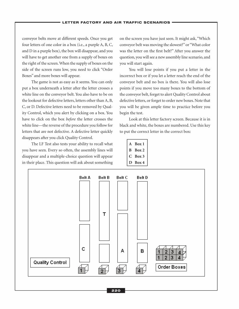
conveyor belts move at different speeds. Once you get
four letters of one color in a box (i.e., a purple A, B, C,
and D in a purple box), the box will disappear, and you
will have to get another one from a supply of boxes on
the right of the screen. When the supply of boxes on the
side of the screen runs low, you need to click “Order
Boxes” and more boxes will appear.
The game is not as easy as it seems. You can only
put a box underneath a letter after the letter crosses a
white line on the conveyor belt. You also have to be on
the lookout for defective letters, letters other than A, B,
C, or D. Defective letters need to be removed by Qual-
ity Control, which you alert by clicking on a box. You
have to click on the box before the letter crosses the
white line—the reverse of the procedure you follow for
letters that are not defective. A defective letter quickly
disappears after you click Quality Control.
The LF Test also tests your ability to recall what
you have seen. Every so often, the assembly lines will
disappear and a multiple-choice question will appear
in their place. This question will ask about something
on the screen you have just seen. It might ask, “Which
conveyor belt was moving the slowest?” or “What color
was the letter on the first belt?” After you answer the
question, you will see a new assembly line scenario, and
you will start again.
You will lose points if you put a letter in the
incorrect box or if you let a letter reach the end of the
conveyor belt and no box is there. You will also lose
points if you move too many boxes to the bottom of
the conveyor belt, forget to alert Quality Control about
defective letters, or forget to order new boxes. Note that
you will be given ample time to practice before you
begin the test.
Look at this letter factory screen. Because it is in
black and white, the boxes are numbered. Use this key
to put the correct letter in the correct box:
A Box 1
B Box 2
C Box 3
D Box 4
220
–LETTER FACTORY AND AIR TRAFFIC SCENARIOS–
ATC_2008b:Layout 1 11/24/08 1:18 PM Page 220
Note that the letter must be below the white line
before you can put it in a box. If it is above the white
line, you take no action. On the actual test, you will
wait until the letter crosses the white line before put-
ting it in a box.
1–3: Answer these questions based on the dia-
gram on the previous page.
1. The letter on Belt A should go in the box at theend of
a. Belt A.
b. Belt B.
c. Belt C.
d. Belt D.
The letter on Belt A is C. According to the key, it should
go in Box 3, and this box is at the end of Belt C, so the
correct answer choice is c.
2. What should you do about the letter on Belt B? a. Take no action.
b. Put it in Box 4.
c. Alert Quality Control.
d. Put it in Box 1.
The letter on Belt B is T, which is defective. It has not
crossed the white line, so you should alert Quality Con-
trol. The correct answer choice is c.
3. The letter on Belt D should go in the box at theend of
a. Belt A.
b. Belt B.
c. Belt C.
d. Belt D.
The letter on Belt D is B. According to the key, it should
go in Box 2, which is at the end of Belt B. The correct
answer choice is b.
4–5: Now, cover the diagram with a piece of paper
and answer these questions.
4. What letter was on Belt A? a. A
b. B
c. C
d. D
5. What was the defective letter? a. J
b. T
c. F
d. L
The answer to question 4 is c. The letter C was on Belt
A. The defective letter was T.
� Air Traff ic Scenarios
The Air Traffic Scenarios Test (ATST) is a simulation
of an ATC radar screen that updates every seven sec-
onds. Your job is to maintain separation between air-
craft represented by data blocks and direct these
aircraft to avoid errors.
The main section of the screen has four exits: A,
B, C, and D. It also has two airports: e and f. Aircraft
can fly at three speeds:
S Slow
M Medium
F Fast
221
–LETTER FACTORY AND AIR TRAFFIC SCENARIOS–
ATC_2008b:Layout 1 11/24/08 1:18 PM Page 221
Aircraft can fly at four altitudes:
1 Low
2 Low to Medium
3 Medium to Fast
4 Fast
Aircraft can fly toward one of four exits or toward
one of two airports. Each aircraft is identified by a data
block consisting of the aircraft’s speed, altitude, and
exit or airport. For example, look at this data block:
F4B
This aircraft is flying fast, at a high altitude, and
toward exit B.
Now try another:
S1e
This aircraft is flying at a slow speed, at a low
altitude, and toward airport e.
Each aircraft also has an arrow indicating the
direction, or heading, in which it is flying.
Your goal is to identify and correct these errors:
� Aircraft flying either too fast or too slow.
Aircraft flying toward an exit should fly at a
fast speed, while aircraft flying toward an
airport should fly at a slow speed.� Aircraft flying at an incorrect altitude. Air-
craft flying toward an exit should fly at a
high altitude, while aircraft flying toward an
airport should fly at a low altitude. � Aircraft flying toward the wrong exit or
airport. If an aircraft is identified as F3A,
the arrow after it should point to exit A, not
to another exit or an airport. If the aircraft
is flying toward an incorrect exit, you need
to change its heading. � Aircraft flying too close together. Aircraft
are required to maintain a separation of five
miles laterally or 1,000 feet vertically. If air-
craft are too close together, you need to sep-
arate them—sometimes quickly, so they do
not collide. � Aircraft flying too close to a boundary. On
this test, the boundary is the line around the
top, bottom, and sides of the screen.
On the actual test, you will use a computer mouse
to make changes. You simply click on the data block
representing an aircraft, and then click on the correct
change on the right of the screen. For example, if you
would like to change an aircraft’s heading, you would
click on the data block for that aircraft and then click
on the correct heading on the right of the screen.
You will also need to scan the Pilot Readback box
on the right of the screen. Sometimes pilots will mis-
interpret your commands. When this happens, you
need to reissue the command by clicking on the aircraft
and then the change.
Keep an eye on the destination of each aircraft on
the screen. Occasionally, an aircraft flying toward an
exit will change its destination and fly toward an air-
port and vice versa.
Points are both awarded and deducted on this
test. You will be awarded points for maintaining cor-
rect separation and making necessary changes in speed
and altitude. You will lose points if you direct an air-
craft to an incorrect destination, do not maintain sep-
aration between aircraft, or do not catch an error in
speed or altitude.
222
–LETTER FACTORY AND AIR TRAFFIC SCENARIOS–
ATC_2008b:Layout 1 11/24/08 1:18 PM Page 222
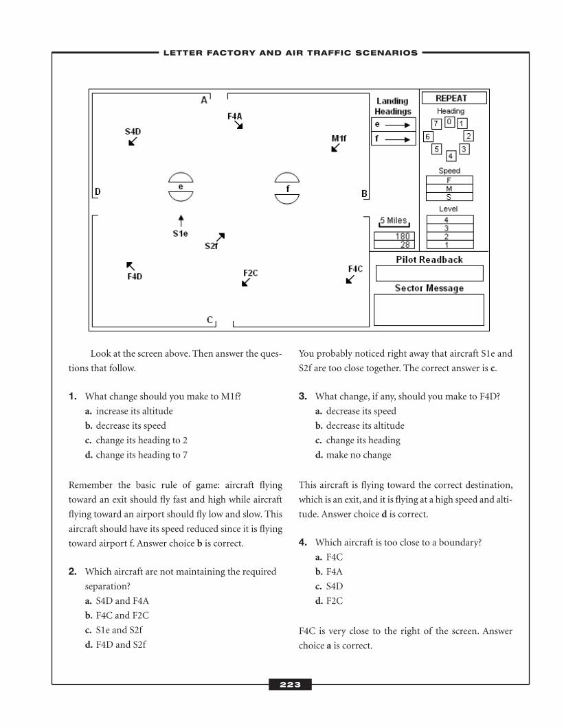
Look at the screen above. Then answer the ques-
tions that follow.
1. What change should you make to M1f? a. increase its altitude
b. decrease its speed
c. change its heading to 2
d. change its heading to 7
Remember the basic rule of game: aircraft flying
toward an exit should fly fast and high while aircraft
flying toward an airport should fly low and slow. This
aircraft should have its speed reduced since it is flying
toward airport f. Answer choice b is correct.
2. Which aircraft are not maintaining the requiredseparation?
a. S4D and F4A
b. F4C and F2C
c. S1e and S2f
d. F4D and S2f
You probably noticed right away that aircraft S1e and
S2f are too close together. The correct answer is c.
3. What change, if any, should you make to F4D? a. decrease its speed
b. decrease its altitude
c. change its heading
d. make no change
This aircraft is flying toward the correct destination,
which is an exit, and it is flying at a high speed and alti-
tude. Answer choice d is correct.
4. Which aircraft is too close to a boundary? a. F4C
b. F4A
c. S4D
d. F2C
F4C is very close to the right of the screen. Answer
choice a is correct.
223
–LETTER FACTORY AND AIR TRAFFIC SCENARIOS–
ATC_2008b:Layout 1 11/24/08 1:18 PM Page 223
5. Which aircraft is flying toward the wrong exit? a. F4C
b. F4D
c. F4A
d. S4D
F4A is flying toward airport f when it should be flying
toward exit A. If you were taking the actual test, you
would change its heading. Answer choice c is correct.
6. What change, if any, should you make to S4D?a. increase its speed
b. reduce its altitude
c. change its heading
d. make no change
This aircraft is flying toward an exit, so it should be fly-
ing at a high speed. You would need to change the S to
F. Answer choice a is correct.
224
–LETTER FACTORY AND AIR TRAFFIC SCENARIOS–
ATC_2008b:Layout 1 11/24/08 1:18 PM Page 224
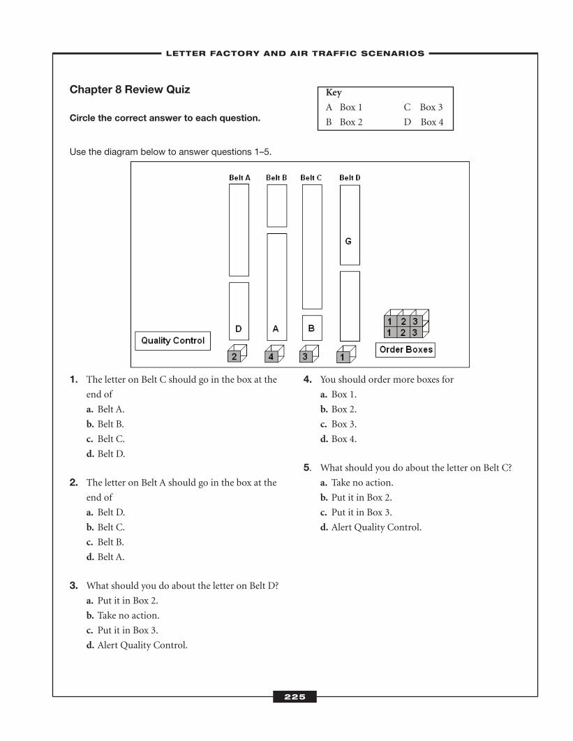
1. The letter on Belt C should go in the box at the
end of
a. Belt A.
b. Belt B.
c. Belt C.
d. Belt D.
2. The letter on Belt A should go in the box at theend of
a. Belt D.
b. Belt C.
c. Belt B.
d. Belt A.
3. What should you do about the letter on Belt D?a. Put it in Box 2.
b. Take no action.
c. Put it in Box 3.
d. Alert Quality Control.
4. You should order more boxes for a. Box 1.
b. Box 2.
c. Box 3.
d. Box 4.
5. What should you do about the letter on Belt C? a. Take no action.
b. Put it in Box 2.
c. Put it in Box 3.
d. Alert Quality Control.
225
Chapter 8 Review Quiz
Circle the correct answer to each question.
Use the diagram below to answer questions 1–5.
Key
A Box 1 C Box 3
B Box 2 D Box 4
–LETTER FACTORY AND AIR TRAFFIC SCENARIOS–
ATC_2008b:Layout 1 11/24/08 1:18 PM Page 225
226
Answer questions 6–10 from memory.
6. What was the defective letter? a. C
b. G
c. D
d. B
7. The defective letter was on a. Belt A.
b. Belt B.
c. Belt C.
d. Belt D.
8. What letter was on Belt C? a. A
b. B
c. C
d. D
9. What letter was on Belt A?a. A
b. B
c. C
d. D
10.What letter was on Belt B?a. A
b. B
c. C
d. D
–LETTER FACTORY AND AIR TRAFFIC SCENARIOS–
ATC_2008b:Layout 1 11/24/08 1:18 PM Page 226
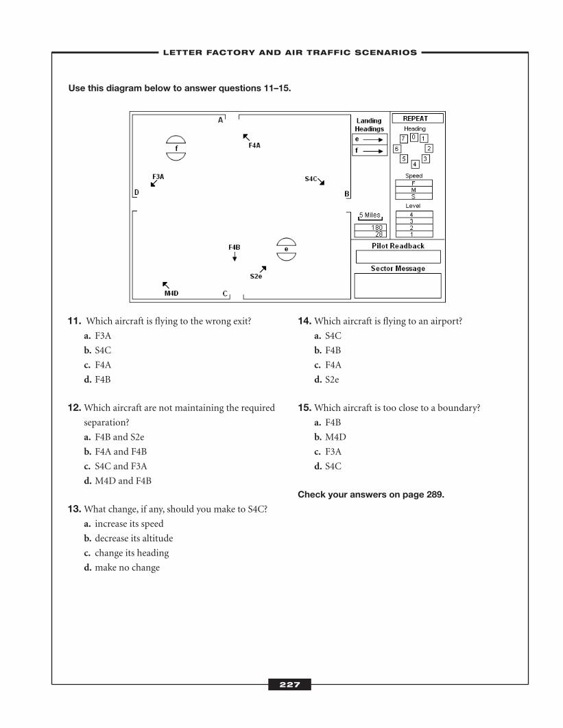
227
Use this diagram below to answer questions 11–15.
11. Which aircraft is flying to the wrong exit? a. F3A
b. S4C
c. F4A
d. F4B
12.Which aircraft are not maintaining the requiredseparation?
a. F4B and S2e
b. F4A and F4B
c. S4C and F3A
d. M4D and F4B
13.What change, if any, should you make to S4C? a. increase its speed
b. decrease its altitude
c. change its heading
d. make no change
14.Which aircraft is flying to an airport? a. S4C
b. F4B
c. F4A
d. S2e
15.Which aircraft is too close to a boundary? a. F4B
b. M4D
c. F3A
d. S4C
Check your answers on page 289.
–LETTER FACTORY AND AIR TRAFFIC SCENARIOS–
ATC_2008b:Layout 1 11/24/08 1:18 PM Page 227

ATC_2008b:Layout 1 11/24/08 1:18 PM Page 228
� Pract ice Test 6—LetterFactory Test
You will answer 100 letter factory questions on this
practice test. You will take the actual Letter Factory
(LF) Test on a computer, and you will use a mouse to
perform tasks. This practice test is similar to the
actual test, and it will help you hone your situational-
awareness skills. You will need a pen or pencil to cir-
cle your answers and a sheet of paper to cover the
diagram to test your ability to recall information.
Follow these rules when taking this practice test:
1. Use this key to place the correct letters in
the correct boxes:
A Box 1
B Box 2
C Box 3
D Box 4
Note that you can only put a letter in a box
if it is below the white line. If it is not, you
should choose the answer choice that says
“take no action.”
2. When a letter other than A, B, C, or D appears on
a conveyor belt, the letter is defective and you
need to alert Quality Control—but only if the
letter is above the white line. If the letter is below
this line, it is too late for Quality Control. In this
case, you cannot do anything about the defective
letter.
3. Boxes are located at the right side of the diagram.
You need to order more when you are out of Box
1, Box 2, Box 3, or Box 4.
4. You need to cover the diagram before answering
some questions. This is to test your ability to
remember what you have seen. Follow the direc-
tions as you answer questions on this
practice test.
Choose the correct answer, and mark the correspon-
ding letter on the answer sheet on page 251.
229
–PRACTICE TEST 6—LETTER FACTORY TEST–
ATC_2008b:Layout 1 11/24/08 1:18 PM Page 229
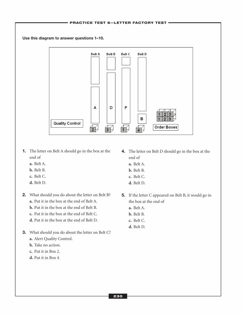
Use this diagram to answer questions 1–10.
1. The letter on Belt A should go in the box at theend of
a. Belt A.
b. Belt B.
c. Belt C.
d. Belt D.
2. What should you do about the letter on Belt B? a. Put it in the box at the end of Belt A.
b. Put it in the box at the end of Belt B.
c. Put it in the box at the end of Belt C.
d. Put it in the box at the end of Belt D.
3. What should you do about the letter on Belt C? a. Alert Quality Control.
b. Take no action.
c. Put it in Box 2.
d. Put it in Box 4.
4. The letter on Belt D should go in the box at theend of
a. Belt A.
b. Belt B.
c. Belt C.
d. Belt D.
5. If the letter C appeared on Belt B, it would go inthe box at the end of
a. Belt A.
b. Belt B.
c. Belt C.
d. Belt D.
230
–PRACTICE TEST 6—LETTER FACTORY TEST–
ATC_2008b:Layout 1 11/24/08 1:18 PM Page 230
231
Now, cover the diagram with a piece of paper.
Answer questions 6–10 from memory.
6. What letter was on Belt A? a. A
b. B
c. C
d. D
7. What letter was on Belt D?a. A
b. B
c. C
d. D
8. There was NOT an extra box on the right side ofthe diagram for number
a. 1.
b. 2.
c. 3.
d. 4.
9. What was the defective letter? a. R
b. P
c. K
d. G
10. The defective letter was on a. Belt A.
b. Belt B.
c. Belt C.
d. Belt D.
–PRACTICE TEST 6—LETTER FACTORY TEST–
ATC_2008b:Layout 1 11/24/08 1:18 PM Page 231
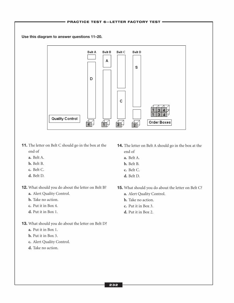
Use this diagram to answer questions 11–20.
11. The letter on Belt C should go in the box at theend of
a. Belt A.
b. Belt B.
c. Belt C.
d. Belt D.
12.What should you do about the letter on Belt B?a. Alert Quality Control.
b. Take no action.
c. Put it in Box 4.
d. Put it in Box 1.
13.What should you do about the letter on Belt D?a. Put it in Box 1.
b. Put it in Box 3.
c. Alert Quality Control.
d. Take no action.
14. The letter on Belt A should go in the box at theend of
a. Belt A.
b. Belt B.
c. Belt C.
d. Belt D.
15.What should you do about the letter on Belt C?a. Alert Quality Control.
b. Take no action.
c. Put it in Box 3.
d. Put it in Box 2.
232
–PRACTICE TEST 6—LETTER FACTORY TEST–
ATC_2008b:Layout 1 11/24/08 1:18 PM Page 232
233
Now, cover the diagram with a piece of paper.
Answer questions 16–20 from memory.
16.What letter was on Belt C?a. A
b. B
c. C
d. D
17.What was the defective letter? a. K
b. R
c. P
d. S
18. The defective letter was on Belt a. A.
b. B.
c. C.
d. D.
19. There was NOT an extra box on the right side ofthe diagram for number
a. 1.
b. 2.
c. 3.
d. 4.
20.What letter was on Belt B?a. A
b. B
c. C
d. D
–PRACTICE TEST 6—LETTER FACTORY TEST–
ATC_2008b:Layout 1 11/24/08 1:18 PM Page 233
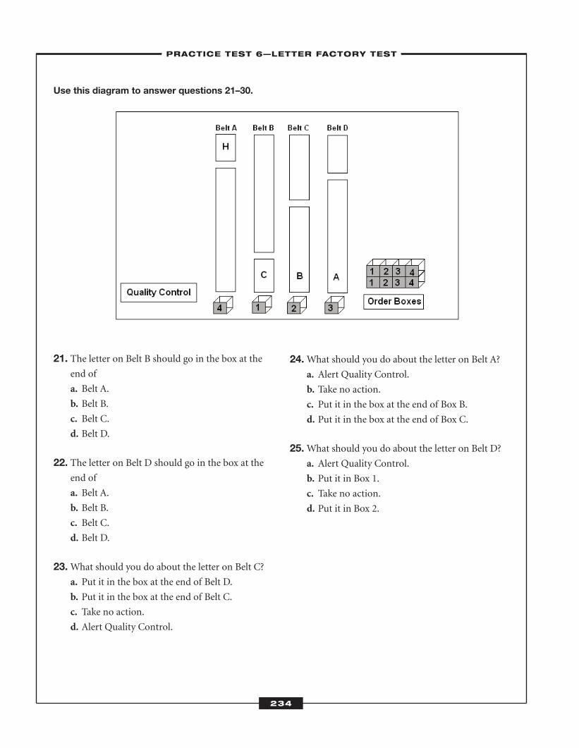
Use this diagram to answer questions 21–30.
21. The letter on Belt B should go in the box at theend of
a. Belt A.
b. Belt B.
c. Belt C.
d. Belt D.
22. The letter on Belt D should go in the box at theend of
a. Belt A.
b. Belt B.
c. Belt C.
d. Belt D.
23.What should you do about the letter on Belt C? a. Put it in the box at the end of Belt D.
b. Put it in the box at the end of Belt C.
c. Take no action.
d. Alert Quality Control.
24.What should you do about the letter on Belt A?a. Alert Quality Control.
b. Take no action.
c. Put it in the box at the end of Box B.
d. Put it in the box at the end of Box C.
25.What should you do about the letter on Belt D? a. Alert Quality Control.
b. Put it in Box 1.
c. Take no action.
d. Put it in Box 2.
234
–PRACTICE TEST 6—LETTER FACTORY TEST–
ATC_2008b:Layout 1 11/24/08 1:18 PM Page 234
235
Now, cover the diagram with a piece of paper.
Answer questions 26–30 from memory.
26.What letter was on Belt C?a. A
b. B
c. C
d. D
27.What was the defective letter?a. R
b. H
c. K
d. B
28. The defective letter was on a. Belt A.
b. Belt B.
c. Belt C.
d. Belt D.
29.What letter was on Belt D?a. D
b. C
c. B
d. A
30. Extra boxes were available to a. 1 only.
b. 1 and 2 only.
c. 1, 2, and 3 only.
d. 1, 2, 3, and 4.
–PRACTICE TEST 6—LETTER FACTORY TEST–
ATC_2008b:Layout 1 11/24/08 1:18 PM Page 235
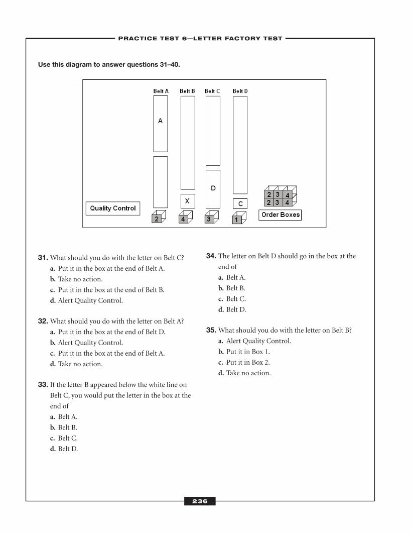
Use this diagram to answer questions 31–40.
31.What should you do with the letter on Belt C?a. Put it in the box at the end of Belt A.
b. Take no action.
c. Put it in the box at the end of Belt B.
d. Alert Quality Control.
32.What should you do with the letter on Belt A? a. Put it in the box at the end of Belt D.
b. Alert Quality Control.
c. Put it in the box at the end of Belt A.
d. Take no action.
33. If the letter B appeared below the white line onBelt C, you would put the letter in the box at the
end of
a. Belt A.
b. Belt B.
c. Belt C.
d. Belt D.
34. The letter on Belt D should go in the box at theend of
a. Belt A.
b. Belt B.
c. Belt C.
d. Belt D.
35.What should you do with the letter on Belt B?a. Alert Quality Control.
b. Put it in Box 1.
c. Put it in Box 2.
d. Take no action.
236
–PRACTICE TEST 6—LETTER FACTORY TEST–
ATC_2008b:Layout 1 11/24/08 1:18 PM Page 236
237
Now, cover the diagram with a piece of paper.
Answer questions 36–40 from memory.
36.What was the defective letter? a. N
b. X
c. Y
d. V
37. The defective letter was on a. Belt A.
b. Belt B.
c. Belt C.
d. Belt D.
38.What letter was on Belt A?a. A
b. B
c. C
d. D
39.What letter was on Belt C?a. A
b. B
c. C
d. D
40.Which letter was above the white line? a. A
b. B
c. C
d. D
–PRACTICE TEST 6—LETTER FACTORY TEST–
ATC_2008b:Layout 1 11/24/08 1:18 PM Page 237
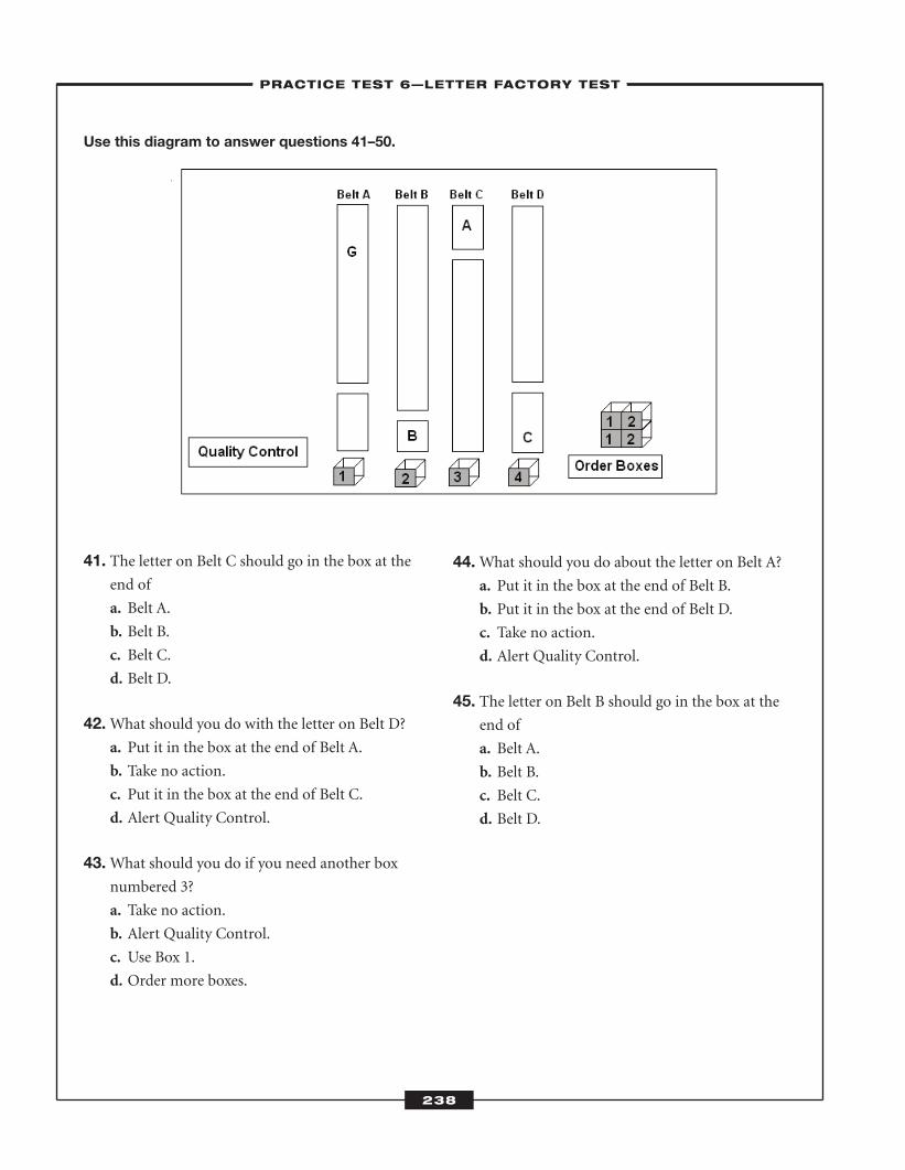
Use this diagram to answer questions 41–50.
41. The letter on Belt C should go in the box at theend of
a. Belt A.
b. Belt B.
c. Belt C.
d. Belt D.
42.What should you do with the letter on Belt D?a. Put it in the box at the end of Belt A.
b. Take no action.
c. Put it in the box at the end of Belt C.
d. Alert Quality Control.
43.What should you do if you need another boxnumbered 3?
a. Take no action.
b. Alert Quality Control.
c. Use Box 1.
d. Order more boxes.
44.What should you do about the letter on Belt A?a. Put it in the box at the end of Belt B.
b. Put it in the box at the end of Belt D.
c. Take no action.
d. Alert Quality Control.
45. The letter on Belt B should go in the box at theend of
a. Belt A.
b. Belt B.
c. Belt C.
d. Belt D.
238
–PRACTICE TEST 6—LETTER FACTORY TEST–
ATC_2008b:Layout 1 11/24/08 1:18 PM Page 238
239
Now, cover the diagram with a piece of paper.
Answer questions 46–50 from memory.
46.What letter was on Belt D?a. A
b. B
c. C
d. D
47.What letter was on Belt C?a. A
b. B
c. C
d. D
48.What was the defective letter? a. O
b. G
c. C
d. Q
49. The defective letter was on Belt a. A.
b. B.
c. C.
d. D.
50. The letter on Belt B was a. D.
b. C.
c. B.
d. A.
–PRACTICE TEST 6—LETTER FACTORY TEST–
ATC_2008b:Layout 1 11/24/08 1:18 PM Page 239
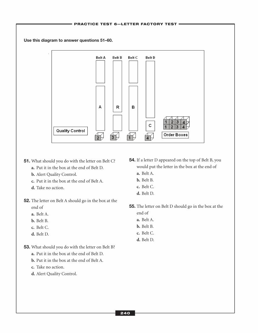
Use this diagram to answer questions 51–60.
51.What should you do with the letter on Belt C?a. Put it in the box at the end of Belt D.
b. Alert Quality Control.
c. Put it in the box at the end of Belt A.
d. Take no action.
52. The letter on Belt A should go in the box at theend of
a. Belt A.
b. Belt B.
c. Belt C.
d. Belt D.
53.What should you do with the letter on Belt B? a. Put it in the box at the end of Belt D.
b. Put it in the box at the end of Belt A.
c. Take no action.
d. Alert Quality Control.
54. If a letter D appeared on the top of Belt B, youwould put the letter in the box at the end of
a. Belt A.
b. Belt B.
c. Belt C.
d. Belt D.
55. The letter on Belt D should go in the box at theend of
a. Belt A.
b. Belt B.
c. Belt C.
d. Belt D.
240
–PRACTICE TEST 6—LETTER FACTORY TEST–
ATC_2008b:Layout 1 11/24/08 1:18 PM Page 240
241
Now, cover the diagram with a piece of paper.
Answer questions 56–60 from memory.
56. The letter on Belt C was a. D.
b. C.
c. B.
d. A.
57. The letter on Belt A was a. A.
b. B.
c. C.
d. D.
58.Which belt had a letter above the white line? a. A
b. B
c. C
d. D
59.What was the defective letter? a. R
b. B
c. D
d. P
60.Which belt had Box 1 at the end of it? a. A
b. B
c. C
d. D
–PRACTICE TEST 6—LETTER FACTORY TEST–
ATC_2008b:Layout 1 11/24/08 1:18 PM Page 241
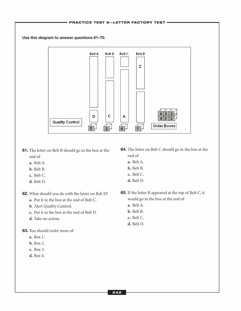
Use this diagram to answer questions 61–70.
61. The letter on Belt B should go in the box at theend of
a. Belt A.
b. Belt B.
c. Belt C.
d. Belt D.
62.What should you do with the letter on Belt D?a. Put it in the box at the end of Belt C.
b. Alert Quality Control.
c. Put it in the box at the end of Belt D.
d. Take no action.
63. You should order more of a. Box 1.
b. Box 2.
c. Box 3.
d. Box 4.
64. The letter on Belt C should go in the box at theend of
a. Belt A.
b. Belt B.
c. Belt C.
d. Belt D.
65. If the letter B appeared at the top of Belt C, itwould go in the box at the end of
a. Belt A.
b. Belt B.
c. Belt C.
d. Belt D.
242
–PRACTICE TEST 6—LETTER FACTORY TEST–
ATC_2008b:Layout 1 11/24/08 1:18 PM Page 242
243
Now, cover the diagram with a piece of paper.
Answer questions 66–70 from memory.
66.What letter was on Belt A?a. D
b. C
c. B
d. A
67.What letter was on Belt C?a. A
b. B
c. C
d. D
68.What was the defective letter?a. X
b. W
c. Z
d. V
69. The defective letter was on a. Belt A.
b. Belt B.
c. Belt C.
d. Belt D.
70.What letter was on Belt B?a. A
b. B
c. C
d. D
–PRACTICE TEST 6—LETTER FACTORY TEST–
ATC_2008b:Layout 1 11/24/08 1:18 PM Page 243
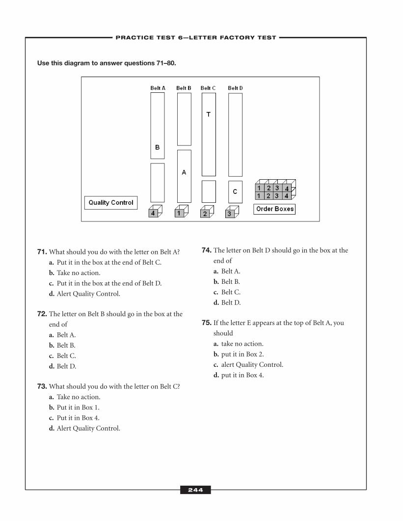
Use this diagram to answer questions 71–80.
71.What should you do with the letter on Belt A?a. Put it in the box at the end of Belt C.
b. Take no action.
c. Put it in the box at the end of Belt D.
d. Alert Quality Control.
72. The letter on Belt B should go in the box at theend of
a. Belt A.
b. Belt B.
c. Belt C.
d. Belt D.
73.What should you do with the letter on Belt C? a. Take no action.
b. Put it in Box 1.
c. Put it in Box 4.
d. Alert Quality Control.
74. The letter on Belt D should go in the box at theend of
a. Belt A.
b. Belt B.
c. Belt C.
d. Belt D.
75. If the letter E appears at the top of Belt A, youshould
a. take no action.
b. put it in Box 2.
c. alert Quality Control.
d. put it in Box 4.
244
–PRACTICE TEST 6—LETTER FACTORY TEST–
ATC_2008b:Layout 1 11/24/08 1:18 PM Page 244
245
Now, cover the diagram with a piece of paper.
Answer questions 76–80 from memory.
76.What letter was above the white line? a. D
b. C
c. B
d. A
77.What letter was on Belt B?a. A
b. B
c. C
d. D
78.What letter was on Belt D? a. D
b. C
c. B
d. A
79. Extra boxes were available for a. Box 1 only.
b. Box 1 and Box 2.
c. Boxes 1, 2, and 3.
d. Boxes 1, 2, 3, and 4.
80.What was the defective letter? a. I
b. L
c. T
d. J
–PRACTICE TEST 6—LETTER FACTORY TEST–
ATC_2008b:Layout 1 11/24/08 1:18 PM Page 245
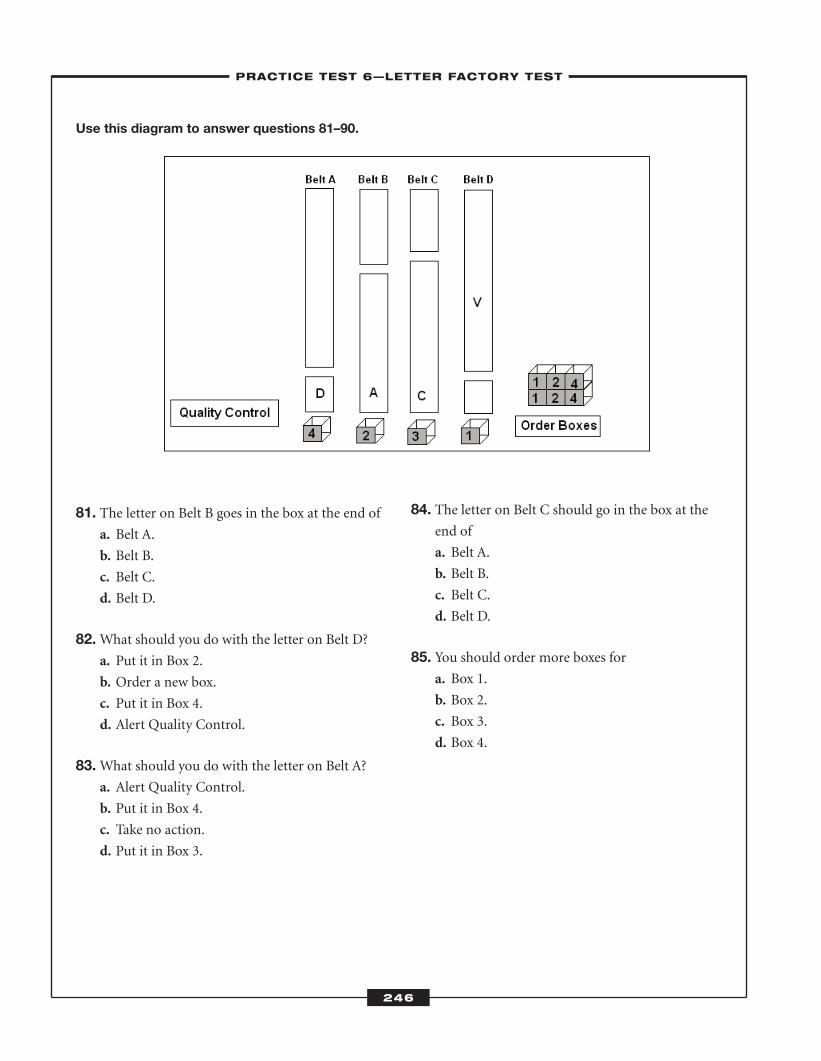
Use this diagram to answer questions 81–90.
81. The letter on Belt B goes in the box at the end of a. Belt A.
b. Belt B.
c. Belt C.
d. Belt D.
82.What should you do with the letter on Belt D?a. Put it in Box 2.
b. Order a new box.
c. Put it in Box 4.
d. Alert Quality Control.
83.What should you do with the letter on Belt A?a. Alert Quality Control.
b. Put it in Box 4.
c. Take no action.
d. Put it in Box 3.
84. The letter on Belt C should go in the box at theend of
a. Belt A.
b. Belt B.
c. Belt C.
d. Belt D.
85. You should order more boxes for a. Box 1.
b. Box 2.
c. Box 3.
d. Box 4.
246
–PRACTICE TEST 6—LETTER FACTORY TEST–
ATC_2008b:Layout 1 11/24/08 1:18 PM Page 246
247
Now, cover the diagram with a piece of paper.
Answer questions 86–90 from memory.
86.What was the defective letter? a. V
b. U
c. W
d. O
87. The defective letter was on a. Belt A.
b. Belt B.
c. Belt C.
d. Belt D.
88.What letter was on Belt B?a. A
b. B
c. C
d. D
89.What letter was on Belt A?a. D
b. C
c. B
d. A
90. Box 1 was at the end of a. Belt A.
b. Belt B.
c. Belt C.
d. Belt D.
–PRACTICE TEST 6—LETTER FACTORY TEST–
ATC_2008b:Layout 1 11/24/08 1:18 PM Page 247
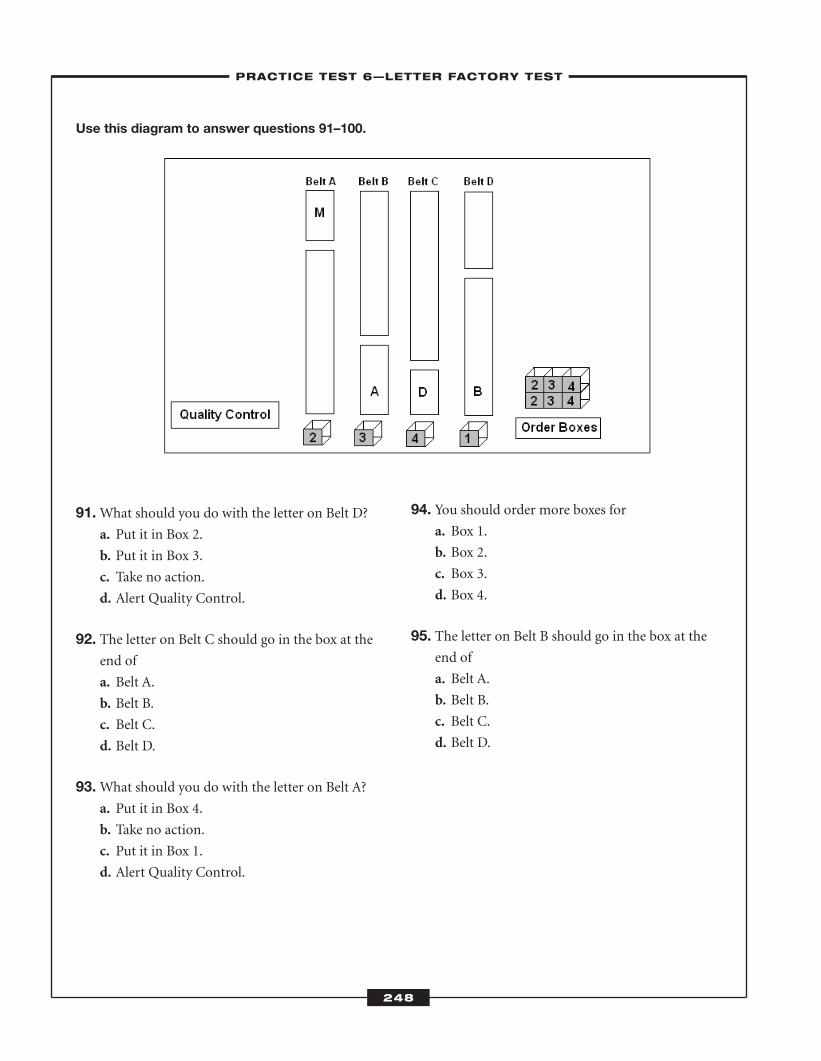
Use this diagram to answer questions 91–100.
91.What should you do with the letter on Belt D?a. Put it in Box 2.
b. Put it in Box 3.
c. Take no action.
d. Alert Quality Control.
92. The letter on Belt C should go in the box at theend of
a. Belt A.
b. Belt B.
c. Belt C.
d. Belt D.
93.What should you do with the letter on Belt A?a. Put it in Box 4.
b. Take no action.
c. Put it in Box 1.
d. Alert Quality Control.
94. You should order more boxes for a. Box 1.
b. Box 2.
c. Box 3.
d. Box 4.
95. The letter on Belt B should go in the box at theend of
a. Belt A.
b. Belt B.
c. Belt C.
d. Belt D.
248
–PRACTICE TEST 6—LETTER FACTORY TEST–
ATC_2008b:Layout 1 11/24/08 1:18 PM Page 248

249
Now, cover the diagram with a piece of paper.
Answer questions 96–100 from memory.
96.What was the defective letter? a. N
b. M
c. V
d. W
97. The defective letter was on a. Belt A.
b. Belt B.
c. Belt C.
d. Belt D.
98.What letter was on Belt B?a. A
b. B
c. C
d. D
99.What letter was on Belt D?a. A
b. B
c. C
d. D
100. What letter was on Belt C?a. A
b. B
c. C
d. D
–PRACTICE TEST 6—LETTER FACTORY TEST–
ATC_2008b:Layout 1 11/24/08 1:18 PM Page 249

ATC_2008b:Layout 1 11/24/08 1:18 PM Page 250
Practice Test 6—Letter Factory Test
–LEARNINGEXPRESS ANSWER SHEET–
251
1. a b c d
2. a b c d
3. a b c d
4. a b c d
5. a b c d
6. a b c d
7. a b c d
8. a b c d
9. a b c d
10. a b c d
11. a b c d
12. a b c d
13. a b c d
14. a b c d
15. a b c d
16. a b c d
17. a b c d
18. a b c d
19. a b c d
20. a b c d
21. a b c d
22. a b c d
23. a b c d
24. a b c d
25. a b c d
26. a b c d
27. a b c d
28. a b c d
29. a b c d
30. a b c d
31. a b c d
32. a b c d
33. a b c d
34. a b c d
35. a b c d
36. a b c d
37. a b c d
38. a b c d
39. a b c d
40. a b c d
41. a b c d
42. a b c d
43. a b c d
44. a b c d
45. a b c d
46. a b c d
47. a b c d
48. a b c d
49. a b c d
50. a b c d
51. a b c d
52. a b c d
53. a b c d
54. a b c d
55. a b c d
56. a b c d
57. a b c d
58. a b c d
59. a b c d
60. a b c d
61. a b c d
62. a b c d
63. a b c d
64. a b c d
65. a b c d
66. a b c d
67. a b c d
68. a b c d
69. a b c d
70. a b c d
71. a b c d
72. a b c d
73. a b c d
74. a b c d
75. a b c d
76. a b c d
77. a b c d
78. a b c d
79. a b c d
80. a b c d
81. a b c d
82. a b c d
83. a b c d
84. a b c d
85. a b c d
86. a b c d
87. a b c d
88. a b c d
89. a b c d
90. a b c d
91. a b c d
92. a b c d
93. a b c d
94. a b c d
95. a b c d
96. a b c d
97. a b c d
98. a b c d
99. a b c d
100. a b c d
ATC_2008b:Layout 1 11/24/08 1:18 PM Page 251
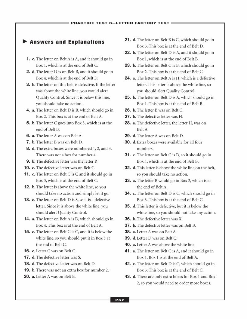
� Answers and Explanat ions
1. c. The letter on Belt A is A, and it should go inBox 1, which is at the end of Belt C.
2. d.The letter D is on Belt B, and it should go inBox 4, which is at the end of Belt D.
3. b.The letter on this belt is defective. If the letterwas above the white line, you would alert
Quality Control. Since it is below this line,
you should take no action.
4. a. The letter on Belt D is B, which should go inBox 2. This box is at the end of Belt A.
5. b.The letter C goes into Box 3, which is at theend of Belt B.
6. a. The letter A was on Belt A. 7. b.The letter B was on Belt D. 8. d.The extra boxes were numbered 1, 2, and 3.
There was not a box for number 4.
9. b.The defective letter was the letter P. 10. c. The defective letter was on Belt C. 11. c. The letter on Belt C is C and it should go in
Box 3, which is at the end of Belt C.
12. b.The letter is above the white line, so youshould take no action and simply let it go.
13. c. The letter on Belt D is S, so it is a defectiveletter. Since it is above the white line, you
should alert Quality Control.
14. a. The letter on Belt A is D, which should go inBox 4. This box is at the end of Belt A.
15. c. The letter on Belt C is C, and it is below thewhite line, so you should put it in Box 3 at
the end of Belt C.
16. c. Letter C was on Belt C. 17. d.The defective letter was S. 18. d.The defective letter was on Belt D. 19. b.There was not an extra box for number 2.20. a. Letter A was on Belt B.
21. d.The letter on Belt B is C, which should go inBox 3. This box is at the end of Belt D.
22. b.The letter on Belt D is A, and it should go inBox 1, which is at the end of Belt B.
23. b.The letter on Belt C is B, which should go inBox 2. This box is at the end of Belt C.
24. a. The letter on Belt A is H, which is a defectiveletter. This letter is above the white line, so
you should alert Quality Control.
25. b.The letter on Belt D is A, which should go inBox 1. This box is at the end of Belt B.
26. b.The letter B was on Belt C.27. b.The defective letter was H. 28. a. The defective letter, the letter H, was on
Belt A.
29. d.The letter A was on Belt D. 30. d.Extra boxes were available for all four
numbers.
31. c. The letter on Belt C is D, so it should go inBox 4, which is at the end of Belt B.
32. d.This letter is above the white line on the belt,so you should take no action.
33. a. The letter B would go in Box 2, which is atthe end of Belt A.
34. c. The letter on Belt D is C, which should go inBox 3. This box is at the end of Belt C.
35. d.This letter is defective, but it is below thewhite line, so you should not take any action.
36. b.The defective letter was X. 37. b.The defective letter was on Belt B. 38. a. Letter A was on Belt A. 39. d.Letter D was on Belt C. 40. a. Letter A was above the white line. 41. a. The letter on Belt C is A, and it should go in
Box 1. Box 1 is at the end of Belt A.
42. c. The letter on Belt D is C, which should go inBox 3. This box is at the end of Belt C.
43. d.There are only extra boxes for Box 1 and Box2, so you would need to order more boxes.
252
–PRACTICE TEST 6—LETTER FACTORY TEST–
ATC_2008b:Layout 1 11/24/08 1:18 PM Page 252
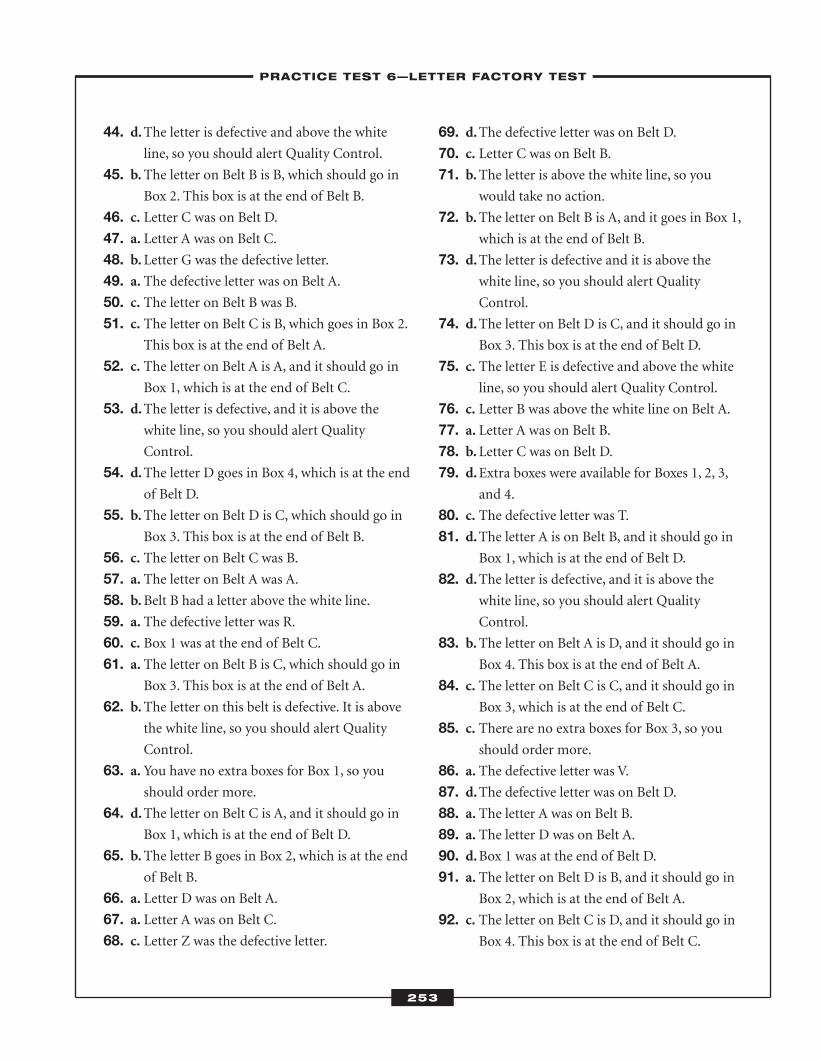
44. d.The letter is defective and above the whiteline, so you should alert Quality Control.
45. b.The letter on Belt B is B, which should go inBox 2. This box is at the end of Belt B.
46. c. Letter C was on Belt D. 47. a. Letter A was on Belt C. 48. b.Letter G was the defective letter. 49. a. The defective letter was on Belt A. 50. c. The letter on Belt B was B. 51. c. The letter on Belt C is B, which goes in Box 2.
This box is at the end of Belt A.
52. c. The letter on Belt A is A, and it should go inBox 1, which is at the end of Belt C.
53. d.The letter is defective, and it is above thewhite line, so you should alert Quality
Control.
54. d.The letter D goes in Box 4, which is at the endof Belt D.
55. b.The letter on Belt D is C, which should go inBox 3. This box is at the end of Belt B.
56. c. The letter on Belt C was B. 57. a. The letter on Belt A was A. 58. b.Belt B had a letter above the white line. 59. a. The defective letter was R. 60. c. Box 1 was at the end of Belt C.61. a. The letter on Belt B is C, which should go in
Box 3. This box is at the end of Belt A.
62. b.The letter on this belt is defective. It is abovethe white line, so you should alert Quality
Control.
63. a. You have no extra boxes for Box 1, so youshould order more.
64. d.The letter on Belt C is A, and it should go inBox 1, which is at the end of Belt D.
65. b.The letter B goes in Box 2, which is at the endof Belt B.
66. a. Letter D was on Belt A. 67. a. Letter A was on Belt C. 68. c. Letter Z was the defective letter.
69. d.The defective letter was on Belt D. 70. c. Letter C was on Belt B. 71. b.The letter is above the white line, so you
would take no action.
72. b.The letter on Belt B is A, and it goes in Box 1,which is at the end of Belt B.
73. d.The letter is defective and it is above thewhite line, so you should alert Quality
Control.
74. d.The letter on Belt D is C, and it should go inBox 3. This box is at the end of Belt D.
75. c. The letter E is defective and above the whiteline, so you should alert Quality Control.
76. c. Letter B was above the white line on Belt A. 77. a. Letter A was on Belt B. 78. b.Letter C was on Belt D. 79. d.Extra boxes were available for Boxes 1, 2, 3,
and 4.
80. c. The defective letter was T. 81. d.The letter A is on Belt B, and it should go in
Box 1, which is at the end of Belt D.
82. d.The letter is defective, and it is above thewhite line, so you should alert Quality
Control.
83. b.The letter on Belt A is D, and it should go inBox 4. This box is at the end of Belt A.
84. c. The letter on Belt C is C, and it should go inBox 3, which is at the end of Belt C.
85. c. There are no extra boxes for Box 3, so youshould order more.
86. a. The defective letter was V. 87. d.The defective letter was on Belt D. 88. a. The letter A was on Belt B. 89. a. The letter D was on Belt A. 90. d.Box 1 was at the end of Belt D. 91. a. The letter on Belt D is B, and it should go in
Box 2, which is at the end of Belt A.
92. c. The letter on Belt C is D, and it should go inBox 4. This box is at the end of Belt C.
253
–PRACTICE TEST 6—LETTER FACTORY TEST–
ATC_2008b:Layout 1 11/24/08 1:18 PM Page 253
93. d.The letter is defective and above the whiteline, so you should alert Quality Control.
94. a. You should order more boxes for Box 1.There are extra boxes for Box 2, Box 3, and
Box 4.
95. d.The letter A is on Belt B. It should go in Box1, which is at the end of Belt D.
96. b.The defective letter was M. 97. a. The defective letter was on Belt A. 98. a. The letter A was on Belt B. 99. b.The letter B was on Belt D. 100.d.The letter D was on Belt C.
254
–PRACTICE TEST 6—LETTER FACTORY TEST–
ATC_2008b:Layout 1 11/24/08 1:18 PM Page 254
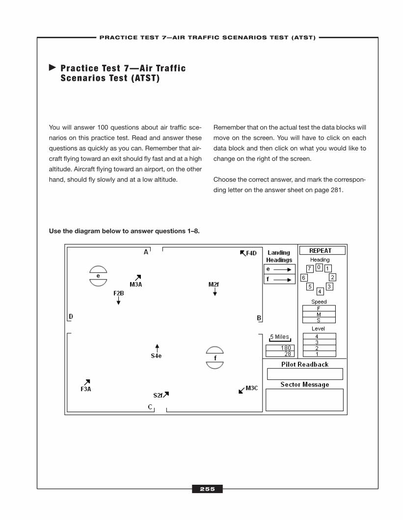
� Pract ice Test 7—Air Traff icScenarios Test (ATST)
You will answer 100 questions about air traffic sce-
narios on this practice test. Read and answer these
questions as quickly as you can. Remember that air-
craft flying toward an exit should fly fast and at a high
altitude. Aircraft flying toward an airport, on the other
hand, should fly slowly and at a low altitude.
Use the diagram below to answer questions 1–8.
Remember that on the actual test the data blocks will
move on the screen. You will have to click on each
data block and then click on what you would like to
change on the right of the screen.
Choose the correct answer, and mark the correspon-
ding letter on the answer sheet on page 281.
255
–PRACTICE TEST 7—AIR TRAFFIC SCENARIOS TEST (ATST)–
ATC_2008b:Layout 1 11/24/08 1:18 PM Page 255
256
1. Which aircraft should have its heading changedto about 5?
a. M2f
b. S2f
c. F4D
d. S4e
2. What change should you make to S4e? a. lower the altitude
b. raise the speed
c. change the heading to 2
d. change the heading to 6
3. Which aircraft are in danger of colliding? a. M2f and F2B
b. F4D and M2f
c. F3A and F2B
d. S2f and S4e
4. What change, if any, should you make to S2f? a. increase its speed
b. change its heading
c. increase its altitude
d. no change is needed
5. What change, if any, should you make to S4e? a. increase its speed
b. lower its altitude
c. change its heading to 2
d. no change is needed
6. You should increase the altitude for a. F2B.
b. S2f.
c. M2f.
d. S4e.
7. The aircraft M3C is in danger of colliding with a. S2f.
b. F4D.
c. F3A.
d. S4e.
8. Which aircraft are most likely less than 5 milesapart?
a. F3A and F2B
b. M3C and S4e
c. F2B and M3A
d. S4e and M2f
–PRACTICE TEST 7—AIR TRAFFIC SCENARIOS TEST (ATST)–
ATC_2008b:Layout 1 11/24/08 1:18 PM Page 256
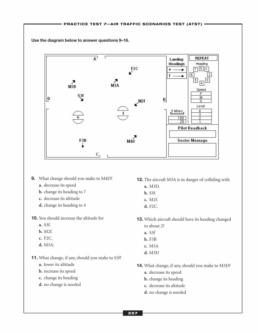
257
Use the diagram below to answer questions 9–16.
9. What change should you make to M4D? a. decrease its speed
b. change its heading to 7
c. decrease its altitude
d. change its heading to 4
10. You should increase the altitude for a. S3f.
b. M2f.
c. F2C.
d. M3A.
11.What change, if any, should you make to S3f? a. lower its altitude
b. increase its speed
c. change its heading
d. no change is needed
12. The aircraft M3A is in danger of colliding with a. M3D.
b. S3f.
c. M2f.
d. F2C.
13.Which aircraft should have its heading changedto about 2?
a. S3f
b. F3B
c. M3A
d. M3D
14.What change, if any, should you make to M3D? a. decrease its speed
b. change its heading
c. decrease its altitude
d. no change is needed
–PRACTICE TEST 7—AIR TRAFFIC SCENARIOS TEST (ATST)–
ATC_2008b:Layout 1 11/24/08 1:18 PM Page 257
258
15.Which aircraft need immediate separation? a. F2C and M3A
b. M3A and M3D
c. F3B and M4D
d. F2C and M2f
16. You should decrease the altitude for a. F2C.
b. M3D.
c. S3f.
d. M4D.
–PRACTICE TEST 7—AIR TRAFFIC SCENARIOS TEST (ATST)–
ATC_2008b:Layout 1 11/24/08 1:18 PM Page 258
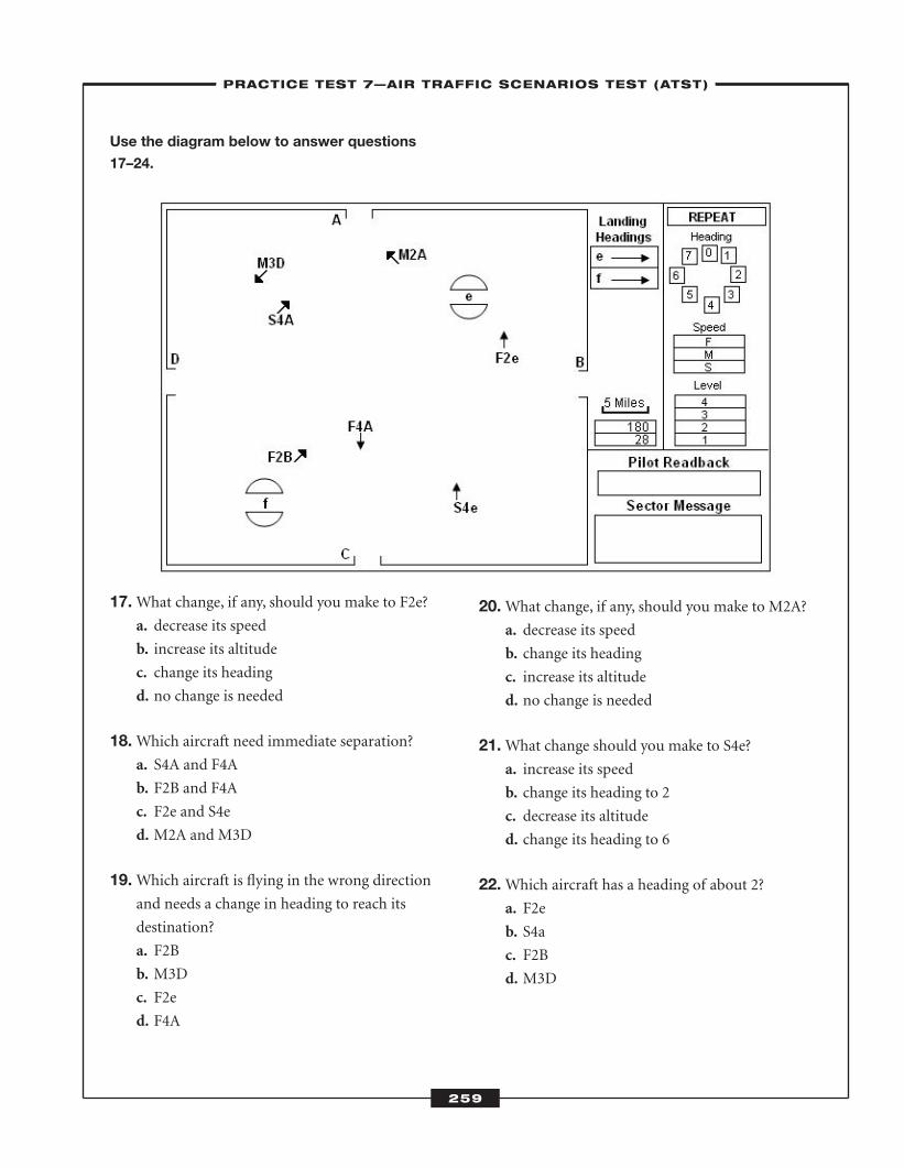
259
Use the diagram below to answer questions
17–24.
17.What change, if any, should you make to F2e? a. decrease its speed
b. increase its altitude
c. change its heading
d. no change is needed
18.Which aircraft need immediate separation? a. S4A and F4A
b. F2B and F4A
c. F2e and S4e
d. M2A and M3D
19.Which aircraft is flying in the wrong directionand needs a change in heading to reach its
destination?
a. F2B
b. M3D
c. F2e
d. F4A
20.What change, if any, should you make to M2A?a. decrease its speed
b. change its heading
c. increase its altitude
d. no change is needed
21.What change should you make to S4e? a. increase its speed
b. change its heading to 2
c. decrease its altitude
d. change its heading to 6
22.Which aircraft has a heading of about 2? a. F2e
b. S4a
c. F2B
d. M3D
–PRACTICE TEST 7—AIR TRAFFIC SCENARIOS TEST (ATST)–
ATC_2008b:Layout 1 11/24/08 1:18 PM Page 259
260
23.What change, if any, should you make to S4A? a. increase its speed
b. decrease its altitude
c. change its heading
d. no change is needed
24.Which aircraft have about the same heading? a. M2A and M3D
b. F2B and F2e
c. S4a and M3D
d. S4e and F2e
–PRACTICE TEST 7—AIR TRAFFIC SCENARIOS TEST (ATST)–
ATC_2008b:Layout 1 11/24/08 1:18 PM Page 260
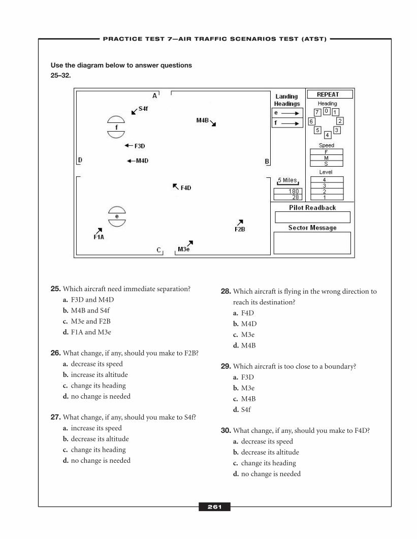
261
Use the diagram below to answer questions
25–32.
25.Which aircraft need immediate separation? a. F3D and M4D
b. M4B and S4f
c. M3e and F2B
d. F1A and M3e
26.What change, if any, should you make to F2B? a. decrease its speed
b. increase its altitude
c. change its heading
d. no change is needed
27.What change, if any, should you make to S4f? a. increase its speed
b. decrease its altitude
c. change its heading
d. no change is needed
28.Which aircraft is flying in the wrong direction toreach its destination?
a. F4D
b. M4D
c. M3e
d. M4B
29.Which aircraft is too close to a boundary? a. F3D
b. M3e
c. M4B
d. S4f
30.What change, if any, should you make to F4D?a. decrease its speed
b. decrease its altitude
c. change its heading
d. no change is needed
–PRACTICE TEST 7—AIR TRAFFIC SCENARIOS TEST (ATST)–
ATC_2008b:Layout 1 11/24/08 1:18 PM Page 261
262
31.Which aircraft have about the same heading? a. F2B and M4B
b. S4f and F1A
c. F4D and M4B
d. M3e and F2B
32.What change should you make to F1A?a. increase its altitude
b. decrease its speed
c. change its heading to 0
d. change its heading to 6
–PRACTICE TEST 7—AIR TRAFFIC SCENARIOS TEST (ATST)–
ATC_2008b:Layout 1 11/24/08 1:18 PM Page 262
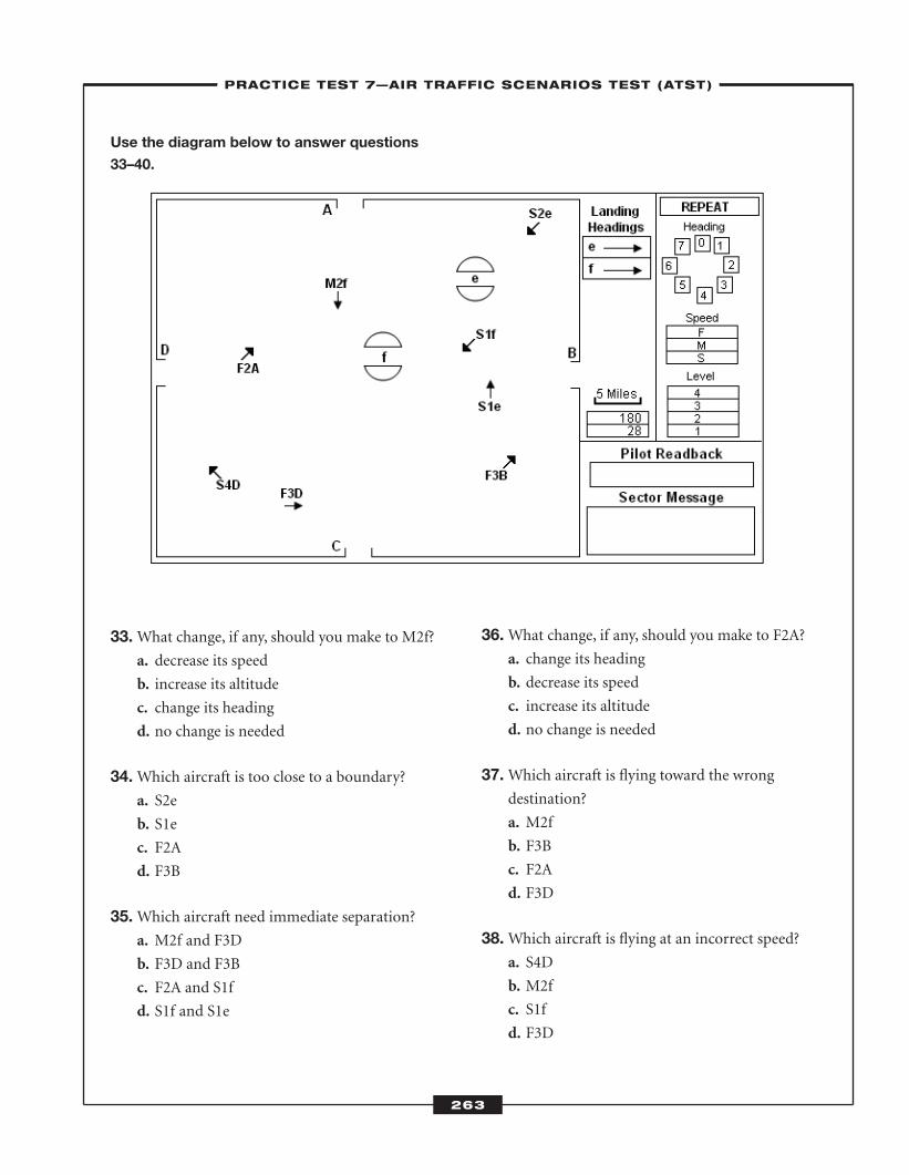
263
Use the diagram below to answer questions
33–40.
33.What change, if any, should you make to M2f? a. decrease its speed
b. increase its altitude
c. change its heading
d. no change is needed
34.Which aircraft is too close to a boundary? a. S2e
b. S1e
c. F2A
d. F3B
35.Which aircraft need immediate separation? a. M2f and F3D
b. F3D and F3B
c. F2A and S1f
d. S1f and S1e
36.What change, if any, should you make to F2A?a. change its heading
b. decrease its speed
c. increase its altitude
d. no change is needed
37.Which aircraft is flying toward the wrong destination?
a. M2f
b. F3B
c. F2A
d. F3D
38.Which aircraft is flying at an incorrect speed? a. S4D
b. M2f
c. S1f
d. F3D
–PRACTICE TEST 7—AIR TRAFFIC SCENARIOS TEST (ATST)–
ATC_2008b:Layout 1 11/24/08 1:18 PM Page 263
264
39.What change, if any, should you make to S1f? a. increase its speed
b. increase its altitude
c. change its heading
d. no change is needed
40.What change should you make to F3D? a. decrease its speed
b. decrease its altitude
c. change its heading
d. no change is needed
–PRACTICE TEST 7—AIR TRAFFIC SCENARIOS TEST (ATST)–
ATC_2008b:Layout 1 11/24/08 1:18 PM Page 264
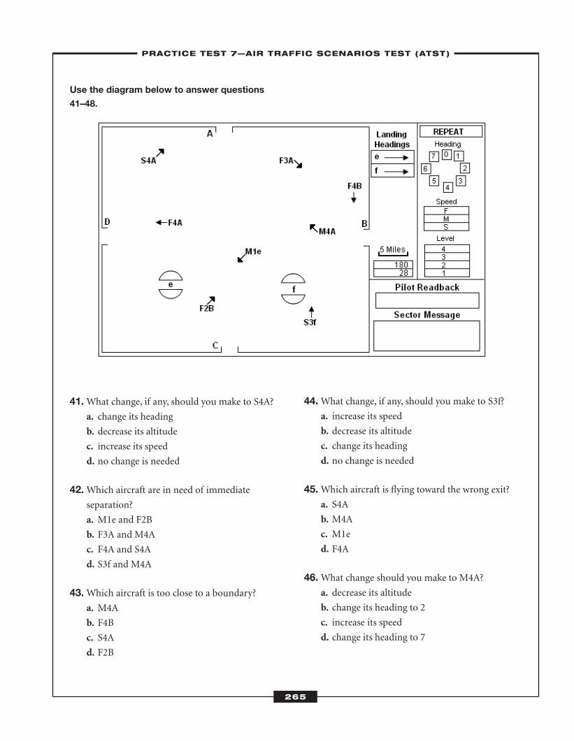
265
Use the diagram below to answer questions
41–48.
41.What change, if any, should you make to S4A?a. change its heading
b. decrease its altitude
c. increase its speed
d. no change is needed
42.Which aircraft are in need of immediate separation?
a. M1e and F2B
b. F3A and M4A
c. F4A and S4A
d. S3f and M4A
43.Which aircraft is too close to a boundary? a. M4A
b. F4B
c. S4A
d. F2B
44.What change, if any, should you make to S3f? a. increase its speed
b. decrease its altitude
c. change its heading
d. no change is needed
45.Which aircraft is flying toward the wrong exit? a. S4A
b. M4A
c. M1e
d. F4A
46.What change should you make to M4A?a. decrease its altitude
b. change its heading to 2
c. increase its speed
d. change its heading to 7
–PRACTICE TEST 7—AIR TRAFFIC SCENARIOS TEST (ATST)–
ATC_2008b:Layout 1 11/24/08 1:18 PM Page 265
266
47.Which aircraft is flying toward the wrong exit? a. M1e
b. F4B
c. F3A
d. F2B
48.What change, if any, should you make to M1e?a. increase its altitude
b. change its heading
c. decrease its speed
d. no change is needed
–PRACTICE TEST 7—AIR TRAFFIC SCENARIOS TEST (ATST)–
ATC_2008b:Layout 1 11/24/08 1:18 PM Page 266
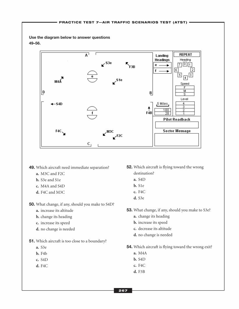
267
Use the diagram below to answer questions
49–56.
49.Which aircraft need immediate separation? a. M3C and F2C
b. S3e and S1e
c. M4A and S4D
d. F4C and M3C
50.What change, if any, should you make to S4D? a. increase its altitude
b. change its heading
c. increase its speed
d. no change is needed
51.Which aircraft is too close to a boundary? a. S3e
b. F4b
c. S4D
d. F4C
52.Which aircraft is flying toward the wrong destination?
a. S4D
b. S1e
c. F4C
d. S3e
53.What change, if any, should you make to S3e? a. change its heading
b. increase its speed
c. decrease its altitude
d. no change is needed
54.Which aircraft is flying toward the wrong exit?a. M4A
b. S4D
c. F4C
d. F3B
–PRACTICE TEST 7—AIR TRAFFIC SCENARIOS TEST (ATST)–
ATC_2008b:Layout 1 11/24/08 1:18 PM Page 267
268
55. You should increase the altitude for a. F2C.
b. S3e.
c. S1e.
d. M4A.
56.Which aircraft have about the same heading? a. S3e and F3B
b. M3C and F2C
c. F4C and S4D
d. F3B and F4B
–PRACTICE TEST 7—AIR TRAFFIC SCENARIOS TEST (ATST)–
268
ATC_2008b:Layout 1 11/24/08 1:18 PM Page 268
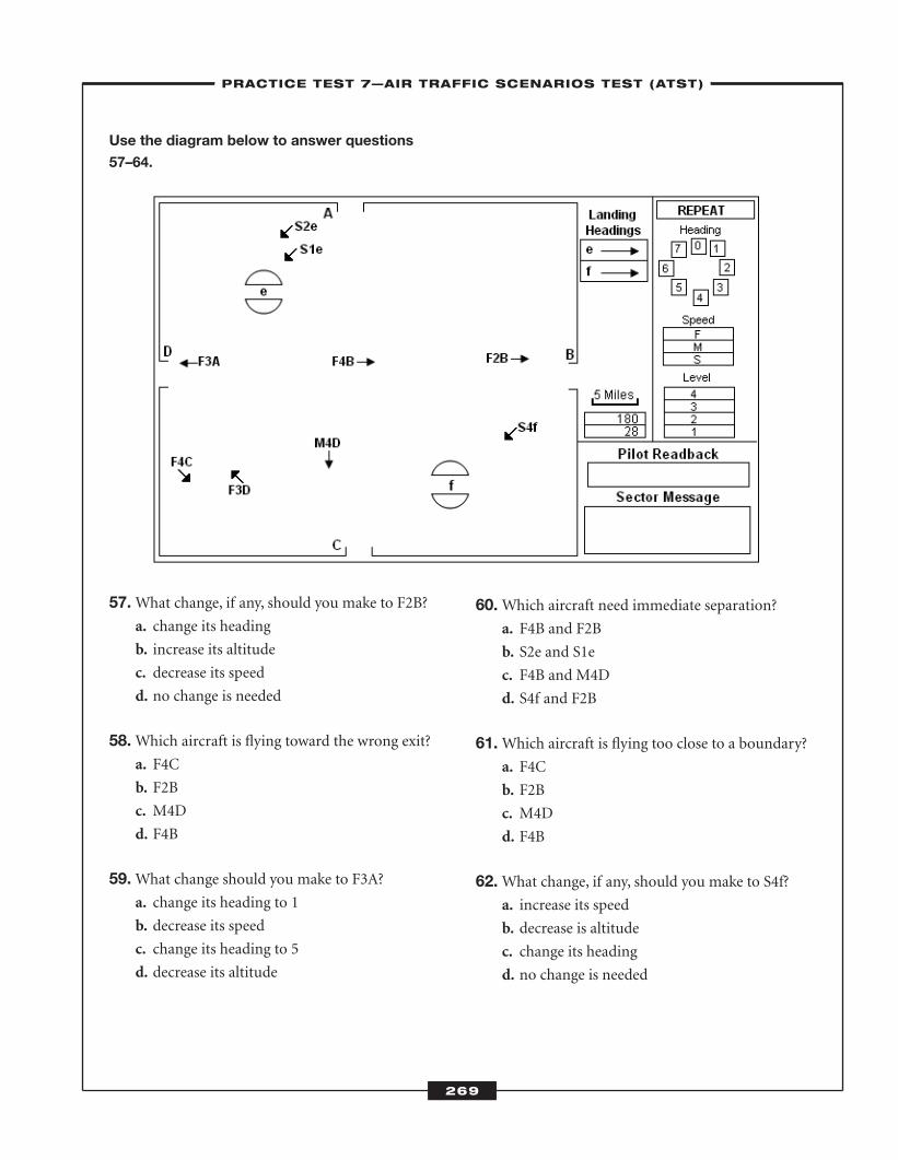
269
Use the diagram below to answer questions
57–64.
57.What change, if any, should you make to F2B? a. change its heading
b. increase its altitude
c. decrease its speed
d. no change is needed
58.Which aircraft is flying toward the wrong exit? a. F4C
b. F2B
c. M4D
d. F4B
59.What change should you make to F3A?a. change its heading to 1
b. decrease its speed
c. change its heading to 5
d. decrease its altitude
60.Which aircraft need immediate separation? a. F4B and F2B
b. S2e and S1e
c. F4B and M4D
d. S4f and F2B
61.Which aircraft is flying too close to a boundary?a. F4C
b. F2B
c. M4D
d. F4B
62.What change, if any, should you make to S4f?a. increase its speed
b. decrease is altitude
c. change its heading
d. no change is needed
–PRACTICE TEST 7—AIR TRAFFIC SCENARIOS TEST (ATST)–
269
ATC_2008b:Layout 1 11/24/08 1:18 PM Page 269
270
63.Which aircraft is headed in the wrong directionto reach its destination?
a. F3A
b. S4f
c. S1e
d. F3D
64.What change, if any, should you make to F4B?a. change its heading
b. decrease its altitude
c. decrease its speed
d. no change is needed
–PRACTICE TEST 7—AIR TRAFFIC SCENARIOS TEST (ATST)–
ATC_2008b:Layout 1 11/24/08 1:18 PM Page 270
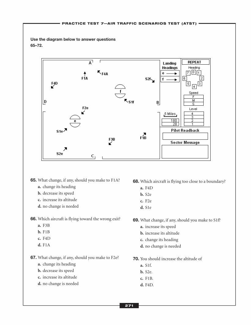
271
Use the diagram below to answer questions
65–72.
65.What change, if any, should you make to F1A?a. change its heading
b. decrease its speed
c. increase its altitude
d. no change is needed
66.Which aircraft is flying toward the wrong exit?a. F3B
b. F1B
c. F4D
d. F1A
67.What change, if any, should you make to F2e?a. change its heading
b. decrease its speed
c. increase its altitude
d. no change is needed
68.Which aircraft is flying too close to a boundary? a. F4D
b. S2e
c. F2e
d. S1e
69.What change, if any, should you make to S1f? a. increase its speed
b. increase its altitude
c. change its heading
d. no change is needed
70. You should increase the altitude of a. S1f.
b. S2e.
c. F1B.
d. F4D.
–PRACTICE TEST 7—AIR TRAFFIC SCENARIOS TEST (ATST)–
ATC_2008b:Layout 1 11/24/08 1:18 PM Page 271
272
71.What change, if any, should you make to S2f? a. change its heading
b. increase its speed
c. increase its altitude
d. no change is needed
72.Which aircraft are in need of immediate separation?
a. F1A and F4A
b. S1f and F2e
c. F3B and F1B
d. F2e and S1e
–PRACTICE TEST 7—AIR TRAFFIC SCENARIOS TEST (ATST)–
ATC_2008b:Layout 1 11/24/08 1:18 PM Page 272
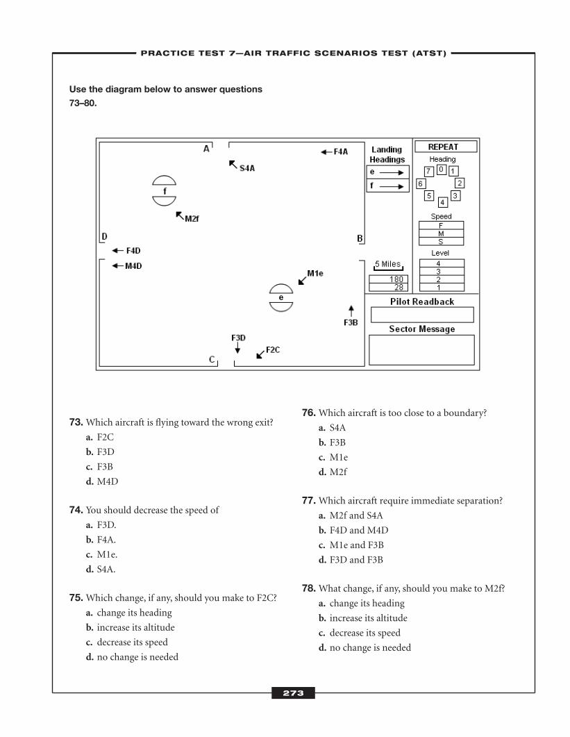
273
Use the diagram below to answer questions
73–80.
73.Which aircraft is flying toward the wrong exit?a. F2C
b. F3D
c. F3B
d. M4D
74. You should decrease the speed of a. F3D.
b. F4A.
c. M1e.
d. S4A.
75.Which change, if any, should you make to F2C?a. change its heading
b. increase its altitude
c. decrease its speed
d. no change is needed
76.Which aircraft is too close to a boundary?a. S4A
b. F3B
c. M1e
d. M2f
77.Which aircraft require immediate separation?a. M2f and S4A
b. F4D and M4D
c. M1e and F3B
d. F3D and F3B
78.What change, if any, should you make to M2f?a. change its heading
b. increase its altitude
c. decrease its speed
d. no change is needed
–PRACTICE TEST 7—AIR TRAFFIC SCENARIOS TEST (ATST)–
ATC_2008b:Layout 1 11/24/08 1:18 PM Page 273
274
79.Which aircraft is too close to a boundary? a. F4A
b. F2C
c. M4D
d. F4D
80. You should decrease the altitude for a. F4A.
b. F3D.
c. M3f.
d. M1e.
–PRACTICE TEST 7—AIR TRAFFIC SCENARIOS TEST (ATST)–
ATC_2008b:Layout 1 11/24/08 1:18 PM Page 274
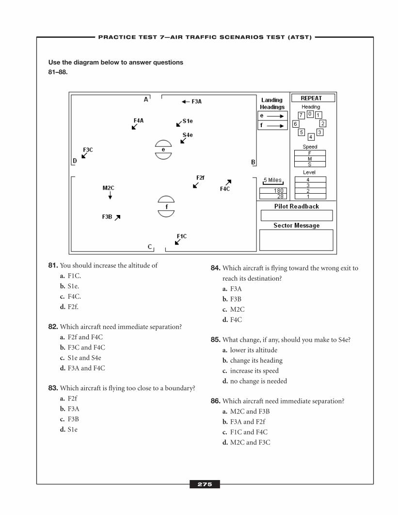
275
Use the diagram below to answer questions
81–88.
81. You should increase the altitude of a. F1C.
b. S1e.
c. F4C.
d. F2f.
82.Which aircraft need immediate separation? a. F2f and F4C
b. F3C and F4C
c. S1e and S4e
d. F3A and F4C
83.Which aircraft is flying too close to a boundary?a. F2f
b. F3A
c. F3B
d. S1e
84.Which aircraft is flying toward the wrong exit toreach its destination?
a. F3A
b. F3B
c. M2C
d. F4C
85.What change, if any, should you make to S4e?a. lower its altitude
b. change its heading
c. increase its speed
d. no change is needed
86.Which aircraft need immediate separation? a. M2C and F3B
b. F3A and F2f
c. F1C and F4C
d. M2C and F3C
–PRACTICE TEST 7—AIR TRAFFIC SCENARIOS TEST (ATST)–
ATC_2008b:Layout 1 11/24/08 1:18 PM Page 275
276
87.What change, if any, should you make to F2f?a. change its heading
b. decrease its speed
c. increase its altitude
d. no change is needed
88.Which aircraft is flying toward the wrong destination?
a. F2f
b. F1C
c. F4A
d. S4e
–PRACTICE TEST 7—AIR TRAFFIC SCENARIOS TEST (ATST)–
ATC_2008b:Layout 1 11/24/08 1:18 PM Page 276
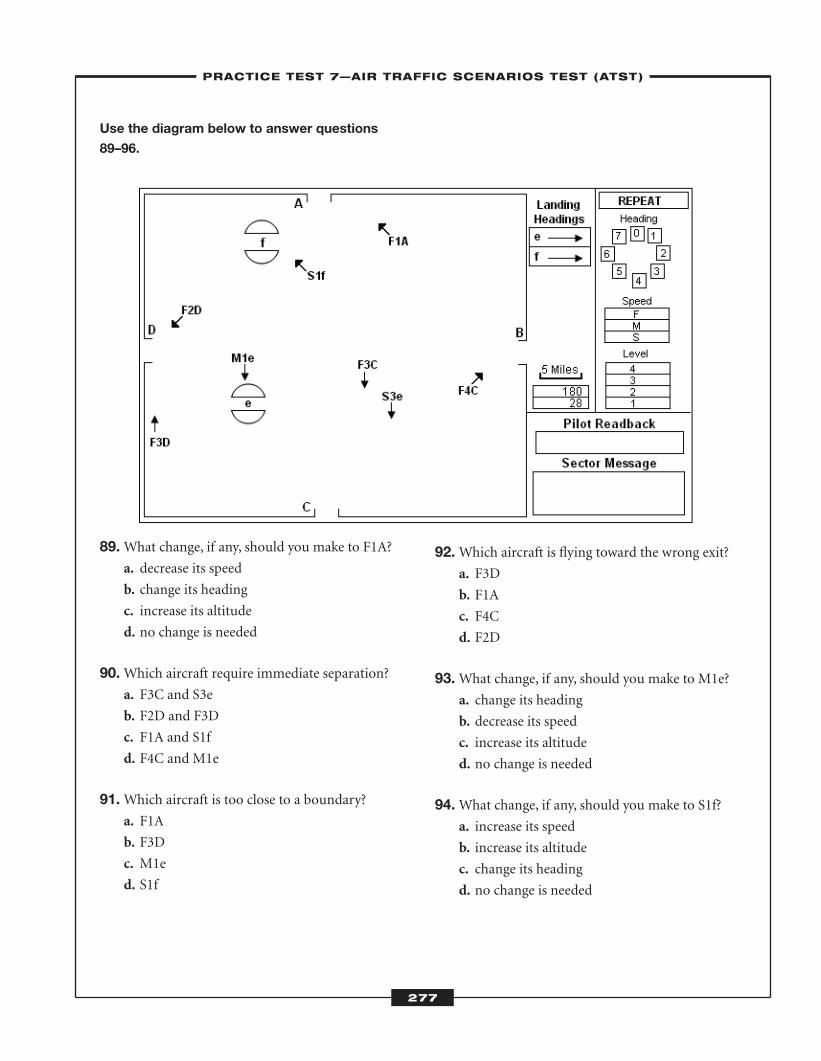
277
Use the diagram below to answer questions
89–96.
89.What change, if any, should you make to F1A?a. decrease its speed
b. change its heading
c. increase its altitude
d. no change is needed
90.Which aircraft require immediate separation?a. F3C and S3e
b. F2D and F3D
c. F1A and S1f
d. F4C and M1e
91.Which aircraft is too close to a boundary? a. F1A
b. F3D
c. M1e
d. S1f
92.Which aircraft is flying toward the wrong exit?a. F3D
b. F1A
c. F4C
d. F2D
93.What change, if any, should you make to M1e? a. change its heading
b. decrease its speed
c. increase its altitude
d. no change is needed
94.What change, if any, should you make to S1f?a. increase its speed
b. increase its altitude
c. change its heading
d. no change is needed
–PRACTICE TEST 7—AIR TRAFFIC SCENARIOS TEST (ATST)–
ATC_2008b:Layout 1 11/24/08 1:18 PM Page 277
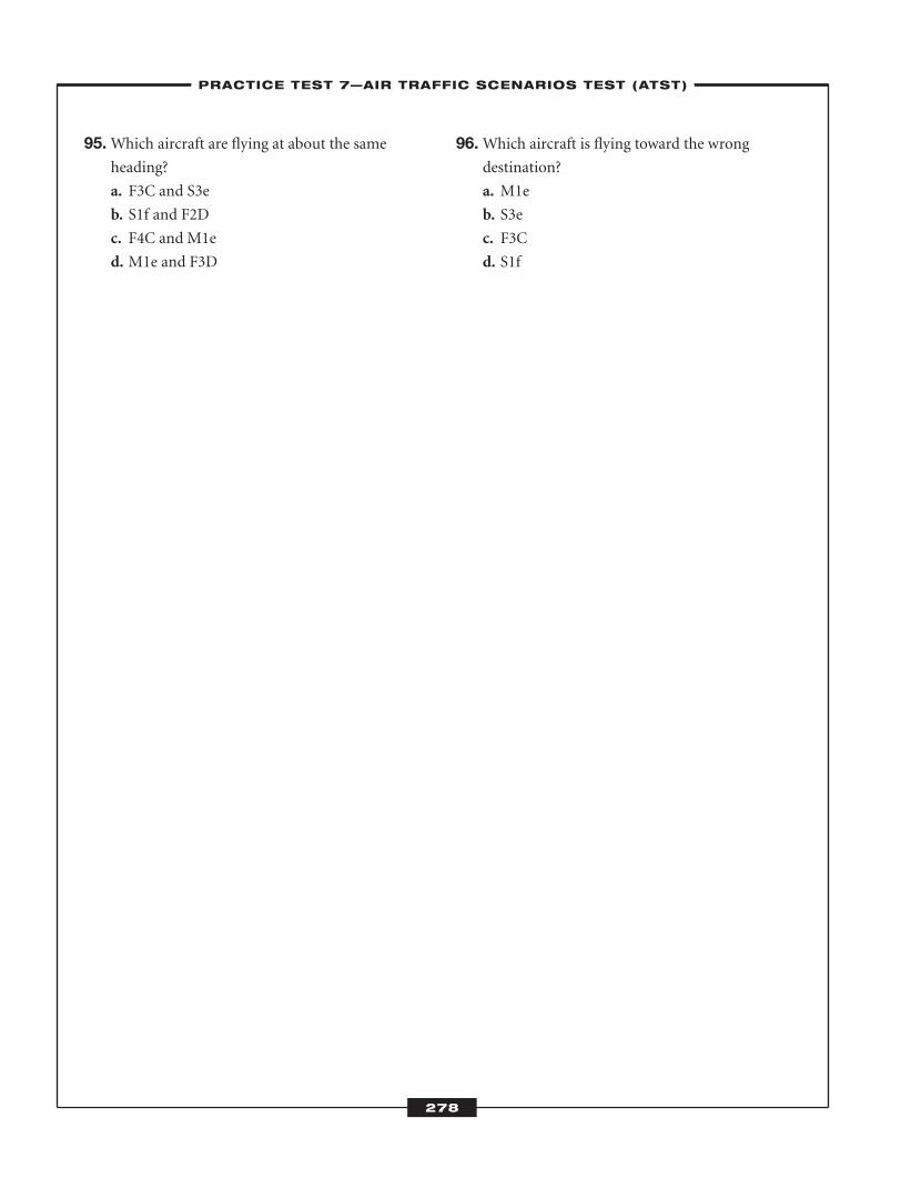
278
95.Which aircraft are flying at about the same heading?
a. F3C and S3e
b. S1f and F2D
c. F4C and M1e
d. M1e and F3D
96.Which aircraft is flying toward the wrong destination?
a. M1e
b. S3e
c. F3C
d. S1f
–PRACTICE TEST 7—AIR TRAFFIC SCENARIOS TEST (ATST)–
ATC_2008b:Layout 1 11/24/08 1:18 PM Page 278
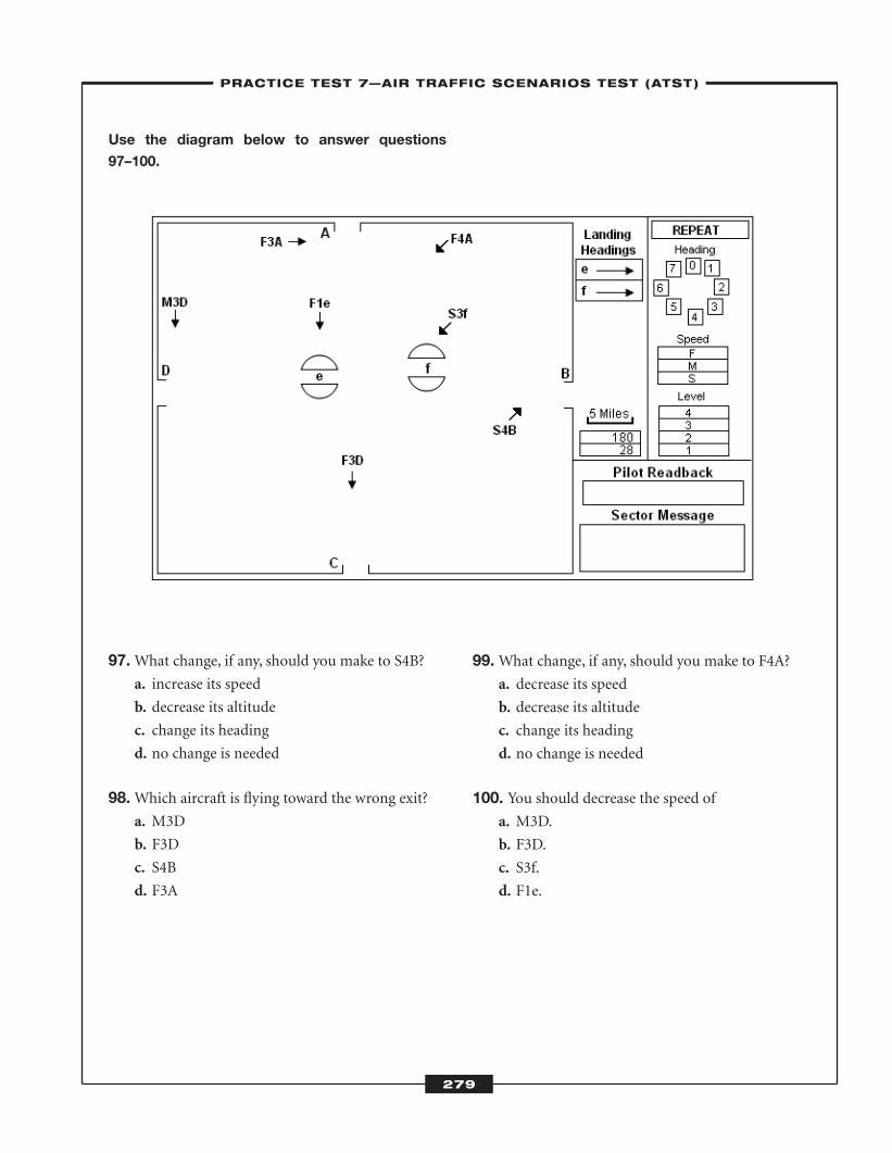
279
Use the diagram below to answer questions
97–100.
97.What change, if any, should you make to S4B?a. increase its speed
b. decrease its altitude
c. change its heading
d. no change is needed
98.Which aircraft is flying toward the wrong exit?a. M3D
b. F3D
c. S4B
d. F3A
99.What change, if any, should you make to F4A?a. decrease its speed
b. decrease its altitude
c. change its heading
d. no change is needed
100. You should decrease the speed of a. M3D.
b. F3D.
c. S3f.
d. F1e.
–PRACTICE TEST 7—AIR TRAFFIC SCENARIOS TEST (ATST)–
ATC_2008b:Layout 1 11/24/08 1:18 PM Page 279

ATC_2008b:Layout 1 11/24/08 1:18 PM Page 280
Practice Test 7—Air Traffic Scenarios Test (ATST)
–LEARNINGEXPRESS ANSWER SHEET–
281
1. a b c d
2. a b c d
3. a b c d
4. a b c d
5. a b c d
6. a b c d
7. a b c d
8. a b c d
9. a b c d
10. a b c d
11. a b c d
12. a b c d
13. a b c d
14. a b c d
15. a b c d
16. a b c d
17. a b c d
18. a b c d
19. a b c d
20. a b c d
21. a b c d
22. a b c d
23. a b c d
24. a b c d
25. a b c d
26. a b c d
27. a b c d
28. a b c d
29. a b c d
30. a b c d
31. a b c d
32. a b c d
33. a b c d
34. a b c d
35. a b c d
36. a b c d
37. a b c d
38. a b c d
39. a b c d
40. a b c d
41. a b c d
42. a b c d
43. a b c d
44. a b c d
45. a b c d
46. a b c d
47. a b c d
48. a b c d
49. a b c d
50. a b c d
51. a b c d
52. a b c d
53. a b c d
54. a b c d
55. a b c d
56. a b c d
57. a b c d
58. a b c d
59. a b c d
60. a b c d
61. a b c d
62. a b c d
63. a b c d
64. a b c d
65. a b c d
66. a b c d
67. a b c d
68. a b c d
69. a b c d
70. a b c d
71. a b c d
72. a b c d
73. a b c d
74. a b c d
75. a b c d
76. a b c d
77. a b c d
78. a b c d
79. a b c d
80. a b c d
81. a b c d
82. a b c d
83. a b c d
84. a b c d
85. a b c d
86. a b c d
87. a b c d
88. a b c d
89. a b c d
90. a b c d
91. a b c d
92. a b c d
93. a b c d
94. a b c d
95. a b c d
96. a b c d
97. a b c d
98. a b c d
99. a b c d
100. a b c d
ATC_2008b:Layout 1 11/24/08 1:19 PM Page 281
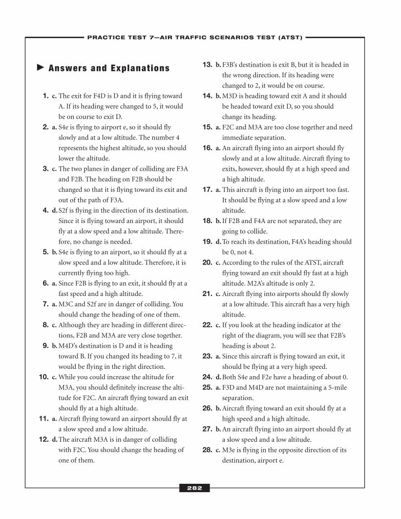
� Answers and Explanat ions
1. c. The exit for F4D is D and it is flying towardA. If its heading were changed to 5, it would
be on course to exit D.
2. a. S4e is flying to airport e, so it should flyslowly and at a low altitude. The number 4
represents the highest altitude, so you should
lower the altitude.
3. c. The two planes in danger of colliding are F3Aand F2B. The heading on F2B should be
changed so that it is flying toward its exit and
out of the path of F3A.
4. d.S2f is flying in the direction of its destination.Since it is flying toward an airport, it should
fly at a slow speed and a low altitude. There-
fore, no change is needed.
5. b. S4e is flying to an airport, so it should fly at aslow speed and a low altitude. Therefore, it is
currently flying too high.
6. a. Since F2B is flying to an exit, it should fly at afast speed and a high altitude.
7. a.M3C and S2f are in danger of colliding. Youshould change the heading of one of them.
8. c. Although they are heading in different direc-tions, F2B and M3A are very close together.
9. b.M4D’s destination is D and it is headingtoward B. If you changed its heading to 7, it
would be flying in the right direction.
10. c.While you could increase the altitude forM3A, you should definitely increase the alti-
tude for F2C. An aircraft flying toward an exit
should fly at a high altitude.
11. a. Aircraft flying toward an airport should fly ata slow speed and a low altitude.
12. d.The aircraft M3A is in danger of collidingwith F2C. You should change the heading of
one of them.
13. b.F3B’s destination is exit B, but it is headed inthe wrong direction. If its heading were
changed to 2, it would be on course.
14. b.M3D is heading toward exit A and it shouldbe headed toward exit D, so you should
change its heading.
15. a. F2C and M3A are too close together and needimmediate separation.
16. a. An aircraft flying into an airport should flyslowly and at a low altitude. Aircraft flying to
exits, however, should fly at a high speed and
a high altitude.
17. a. This aircraft is flying into an airport too fast.It should be flying at a slow speed and a low
altitude.
18. b. If F2B and F4A are not separated, they aregoing to collide.
19. d.To reach its destination, F4A’s heading shouldbe 0, not 4.
20. c. According to the rules of the ATST, aircraftflying toward an exit should fly fast at a high
altitude. M2A’s altitude is only 2.
21. c. Aircraft flying into airports should fly slowlyat a low altitude. This aircraft has a very high
altitude.
22. c. If you look at the heading indicator at theright of the diagram, you will see that F2B’s
heading is about 2.
23. a. Since this aircraft is flying toward an exit, itshould be flying at a very high speed.
24. d.Both S4e and F2e have a heading of about 0.25. a. F3D and M4D are not maintaining a 5-mile
separation.
26. b.Aircraft flying toward an exit should fly at ahigh speed and a high altitude.
27. b.An aircraft flying into an airport should fly ata slow speed and a low altitude.
28. c.M3e is flying in the opposite direction of itsdestination, airport e.
282
–PRACTICE TEST 7—AIR TRAFFIC SCENARIOS TEST (ATST)–
ATC_2008b:Layout 1 11/24/08 1:19 PM Page 282
29. b.M3e is too close to the bottom of the dia-gram, which is a boundary.
30. d.F4D is flying at a high speed and a high alti-tude, which is correct for an aircraft flying
toward an exit. It is also flying at the correct
heading, so no change is needed.
31. d.M3e and F2B both have a heading of about 2.32. a. Aircraft flying to exits should fly high and
fast.
33. a. Since this aircraft is flying to an airport, youshould decrease its speed.
34. a. S2e is too close to the edge of the diagram,which is a boundary.
35. d.S1f and S1e may collide if they are not separated.
36. c. F2A is flying toward an exit, so it should havea high speed and a high altitude. An altitude
of 2 is low.
37. d.F3D is flying away from its destination, so itsheading should be changed.
38. a. An aircraft flying toward an exit should havea fast speed.
39. d.Since S1f is flying to an airport, the speed andaltitude should be low. Its heading is also fine,
so no change is needed.
40. c. F3D is flying away from exit D, so its headingshould be changed.
41. c. Since S4A is flying toward an exit, it shouldbe flying at a higher speed.
42. a.M1e and F2B are heading toward oneanother, so you need to separate them
immediately.
43. b.F4B is too close to the side of the diagram,which is a boundary.
44. b.Aircraft flying to airports should fly at a lowaltitude and a slow speed.
45. d.F4A is flying toward exit D instead of exit A. 46. c. Since M4A is flying toward an exit, it should
be flying at a high speed.
47. c. F3A is flying toward exit B instead of exit A. 48. c. Since M1e is flying to an airport, it should fly
at a slow speed.
49. a.M3C and F2C are not 5 miles apart, so theyneed immediate separation.
50. c. Since S4D is flying to an exit, it should be fly-ing at a high speed.
51. b.F4B is very close to the side of the diagram,which is a boundary.
52. b. S1e should be flying toward airport e, but it isflying toward airport f.
53. c. S3e is flying toward an airport, so it should beflying at a slow speed and a low altitude.
54. d.F3B should be flying toward exit B, but it isheaded toward exit A.
55. a. F2C is flying to an exit, so it should fly at ahigh altitude.
56. b.Both M3C and F2C have a heading that isabout 5.
57. b.F2B is flying toward an exit, so it should havea high altitude.
58. c.M4D should be flying toward exit D, but it isheaded toward exit C.
59. a. F3A is flying toward exit D, and it should beflying toward exit A. Its heading should be
changed to 1.
60. b. S2e and S1e are flying too close together.They are closer than 5 miles apart.
61. a. F4C is too close to the side of the diagram,which is a boundary.
62. b. S4f is heading toward an airport, so its alti-tude should be low.
63. a. F3A should be headed toward exit A, but it isflying toward exit D.
64. d.F4B’s heading, altitude, and speed are fine.65. c. F1A is flying to an exit, so it should be flying
at a higher altitude.
66. a. F3B should be flying toward exit B, but it isheaded toward exit C.
283
–PRACTICE TEST 7—AIR TRAFFIC SCENARIOS TEST (ATST)–
ATC_2008b:Layout 1 11/24/08 1:19 PM Page 283
67. b.F1A is flying toward an airport, so you shoulddecrease its speed.
68. b. S2e is too close to the bottom of the diagram,which is a boundary.
69. d.S1f is flying in the right direction and at a lowspeed and altitude, which is correct for an air-
craft flying to an airport.
70. c. You should increase the altitude of F1Bbecause it is flying toward an exit.
71. a. S2f is not flying toward airport f, so its head-ing should be changed.
72. a. If you look at the mile indicator to the rightof the diagram, you will see that F1A and F4A
are not the required 5 miles apart.
73. b.F3D should be flying toward exit D, but it isflying toward exit C.
74. c.M1e is flying toward an airport, so it shouldfly at a low speed.
75. b.F2C is flying to an exit, so it should fly at ahigh altitude.
76. b.F3B is too close to the right side of the dia-gram, which is a boundary.
77. b.F4D and M4D are not 5 miles apart, so theyneed to be separated immediately.
78. c.M2f is flying toward an airport, so it shouldfly at a slow speed.
79. a. F4A is flying too close to the top of the dia-gram, which is a boundary.
80. c.M3f is flying toward an airport, so it shouldfly at a low altitude.
81. a. F1C is flying toward an exit, so it should havea high altitude.
82. c. S1e and S4e are not flying 5 miles apart, therequired distance.
83. b.F3A is flying too close to the top of the dia-gram, which is a boundary.
84. d.F4C should be flying toward exit C, but it isflying toward exit B.
85. a. S4e should be flying at a low altitude, since itis flying toward an airport.
86. a.M2C and F3B are close together and about tocollide. They need immediate separation.
87. b.F2f is flying to an airport, so its speed shouldbe much lower.
88. c. F4A should be flying toward exit A, but it isflying toward exit D.
89. c. F1A is flying to an exit, so it should fly at ahigher altitude.
90. a. F3C and S3e are very close. They are requiredto be at least 5 miles apart.
91. b.F3D is too close to the side of the diagram,which is a boundary.
92. c. F4C is flying toward exit B when it should beheaded toward exit C.
93. b.M1e is flying toward an airport, so it shouldbe flying at a slow speed.
94. d.S1f is flying at an appropriate speed and alti-tude and is headed in the correct direction.
95. a. F3C and S3e are both flying at the same head-ing, which is about 3.
96. b. S3e should be flying toward airport e, but it isflying toward exit C.
97. a. S4B is flying to an exit, so its speed should behigh.
98. b.F3D is flying to exit C when it should flytoward exit D.
99. c. F4A is not flying in the direction of its exit, soits heading should be changed.
100.d.F1e is flying toward an airport, so it should beflying at a low speed.
284
–PRACTICE TEST 7—AIR TRAFFIC SCENARIOS TEST (ATST)–
ATC_2008b:Layout 1 11/24/08 1:19 PM Page 284
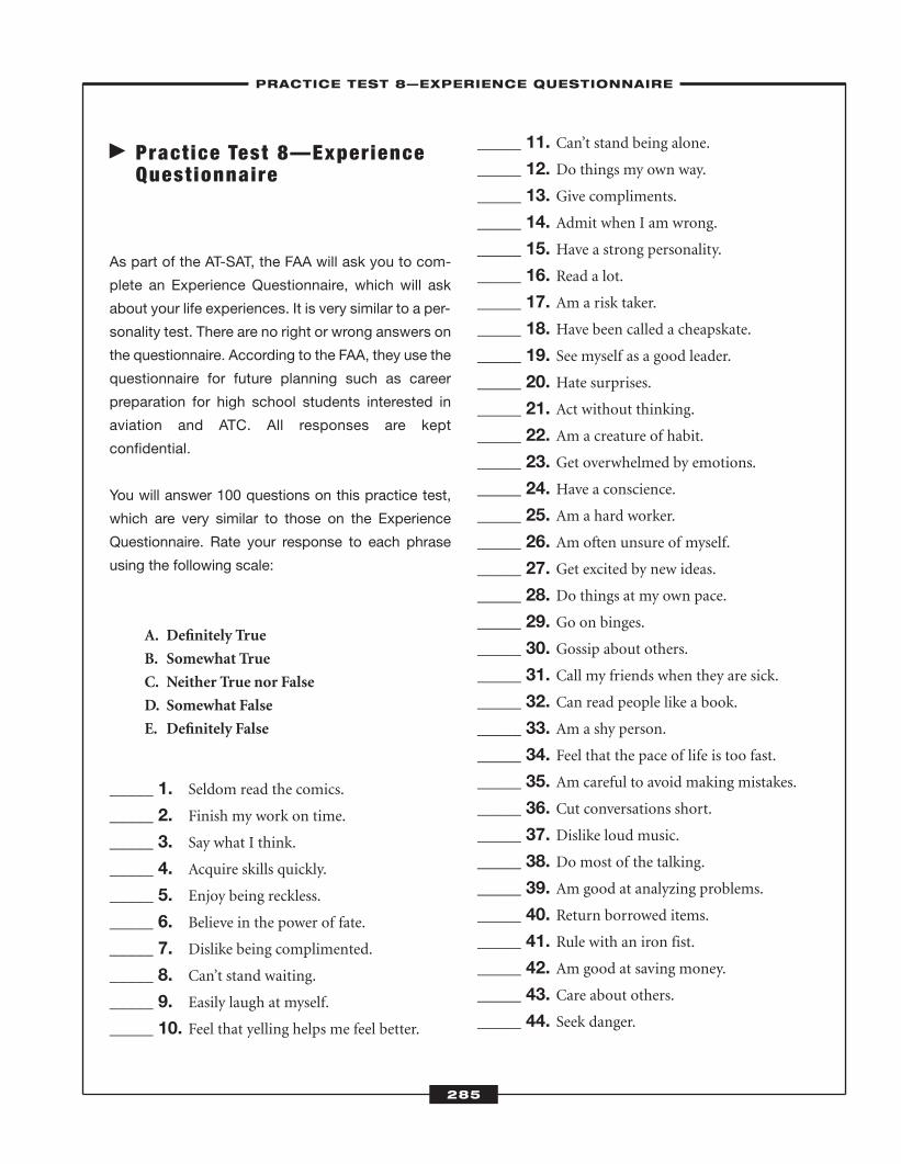
� Pract ice Test 8—ExperienceQuest ionnaire
As part of the AT-SAT, the FAA will ask you to com-
plete an Experience Questionnaire, which will ask
about your life experiences. It is very similar to a per-
sonality test. There are no right or wrong answers on
the questionnaire. According to the FAA, they use the
questionnaire for future planning such as career
preparation for high school students interested in
aviation and ATC. All responses are kept
confidential.
You will answer 100 questions on this practice test,
which are very similar to those on the Experience
Questionnaire. Rate your response to each phrase
using the following scale:
A. Definitely True
B. Somewhat True
C. Neither True nor False
D. Somewhat False
E. Definitely False
_____ 1. Seldom read the comics.
_____ 2. Finish my work on time.
_____ 3. Say what I think.
_____ 4. Acquire skills quickly.
_____ 5. Enjoy being reckless.
_____ 6. Believe in the power of fate.
_____ 7. Dislike being complimented.
_____ 8. Can’t stand waiting.
_____ 9. Easily laugh at myself.
_____ 10. Feel that yelling helps me feel better.
_____ 11. Can’t stand being alone.
_____ 12. Do things my own way.
_____ 13. Give compliments.
_____ 14. Admit when I am wrong.
_____ 15. Have a strong personality.
_____ 16. Read a lot.
_____ 17. Am a risk taker.
_____ 18. Have been called a cheapskate.
_____ 19. See myself as a good leader.
_____ 20. Hate surprises.
_____ 21. Act without thinking.
_____ 22. Am a creature of habit.
_____ 23. Get overwhelmed by emotions.
_____ 24. Have a conscience.
_____ 25. Am a hard worker.
_____ 26. Am often unsure of myself.
_____ 27. Get excited by new ideas.
_____ 28. Do things at my own pace.
_____ 29. Go on binges.
_____ 30. Gossip about others.
_____ 31. Call my friends when they are sick.
_____ 32. Can read people like a book.
_____ 33. Am a shy person.
_____ 34. Feel that the pace of life is too fast.
_____ 35. Am careful to avoid making mistakes.
_____ 36. Cut conversations short.
_____ 37. Dislike loud music.
_____ 38. Do most of the talking.
_____ 39. Am good at analyzing problems.
_____ 40. Return borrowed items.
_____ 41. Rule with an iron fist.
_____ 42. Am good at saving money.
_____ 43. Care about others.
_____ 44. Seek danger.
285
–PRACTICE TEST 8—EXPERIENCE QUESTIONNAIRE–
ATC_2008b:Layout 1 11/24/08 1:19 PM Page 285
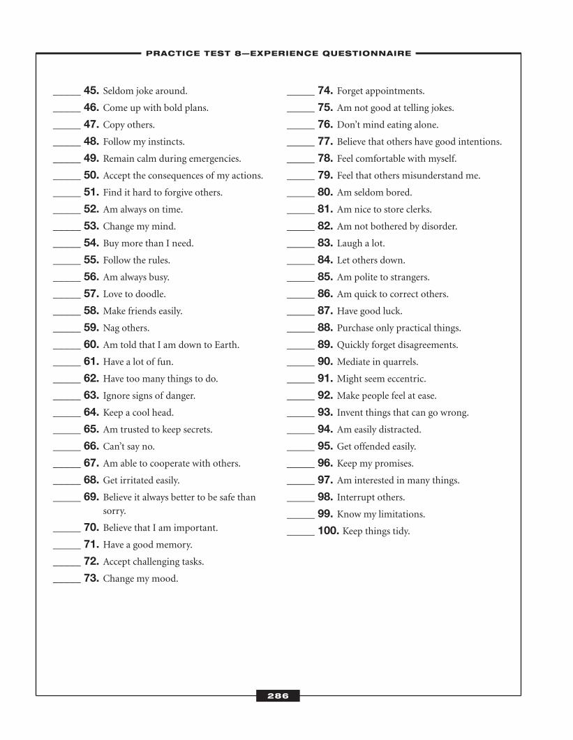
_____ 45. Seldom joke around.
_____ 46. Come up with bold plans.
_____ 47. Copy others.
_____ 48. Follow my instincts.
_____ 49. Remain calm during emergencies.
_____ 50. Accept the consequences of my actions.
_____ 51. Find it hard to forgive others.
_____ 52. Am always on time.
_____ 53. Change my mind.
_____ 54. Buy more than I need.
_____ 55. Follow the rules.
_____ 56. Am always busy.
_____ 57. Love to doodle.
_____ 58. Make friends easily.
_____ 59. Nag others.
_____ 60. Am told that I am down to Earth.
_____ 61. Have a lot of fun.
_____ 62. Have too many things to do.
_____ 63. Ignore signs of danger.
_____ 64. Keep a cool head.
_____ 65. Am trusted to keep secrets.
_____ 66. Can’t say no.
_____ 67. Am able to cooperate with others.
_____ 68. Get irritated easily.
_____ 69. Believe it always better to be safe thansorry.
_____ 70. Believe that I am important.
_____ 71. Have a good memory.
_____ 72. Accept challenging tasks.
_____ 73. Change my mood.
_____ 74. Forget appointments.
_____ 75. Am not good at telling jokes.
_____ 76. Don’t mind eating alone.
_____ 77. Believe that others have good intentions.
_____ 78. Feel comfortable with myself.
_____ 79. Feel that others misunderstand me.
_____ 80. Am seldom bored.
_____ 81. Am nice to store clerks.
_____ 82. Am not bothered by disorder.
_____ 83. Laugh a lot.
_____ 84. Let others down.
_____ 85. Am polite to strangers.
_____ 86. Am quick to correct others.
_____ 87. Have good luck.
_____ 88. Purchase only practical things.
_____ 89. Quickly forget disagreements.
_____ 90. Mediate in quarrels.
_____ 91. Might seem eccentric.
_____ 92. Make people feel at ease.
_____ 93. Invent things that can go wrong.
_____ 94. Am easily distracted.
_____ 95. Get offended easily.
_____ 96. Keep my promises.
_____ 97. Am interested in many things.
_____ 98. Interrupt others.
_____ 99. Know my limitations.
_____ 100. Keep things tidy.
286
–PRACTICE TEST 8—EXPERIENCE QUESTIONNAIRE–
ATC_2008b:Layout 1 11/24/08 1:19 PM Page 286
287
� Chapter Review Answers
Chapter 1
1. b.
2. d.
3. d.
4. a.
5. c.
6. b.
7. a.
8. c.
9. a.
10. c.
Chapter 2
1. b.
2. b.
3. c.
4. d.
5. c.
6. a.
7. a.
8. c.
9. a.
10. b.11. b.12. b.13. d.14. c.15. b.
Chapter 3
1. c.
2. a.
3. a.
4. d.
5. d.
6. d.
7. b.
8. a.
9. c.
10. c.11. c.12. a.13. d.
Appendix
ATC_2008b:Layout 1 11/24/08 1:19 PM Page 287
–APPENDIX–
288
14. c.15. c.
Chapter 4
1. c.
2. a.
3. c.
4. c.
5. a.
6. b.
7. a.
8. c.
9. b.
10. b.
Chapter 5
1. c.
2. b.
3. a.
4. b.
5. c.
6. a.
7. d.
8. d.
9. a.
10. a.11. c.12. a.13. a.14. b.15. c.16. c.17. d.18. d.19. b.20. b.
Chapter 6
1. d.
2. b.
3. c.
4. c.
5. b.
6. a.
7. b.
8. b.
9. b.
10. c.11. d.12. b.13. a.14. c.15. d.16. b.17. a.18. c.19. d.20. b.
Chapter 7
1. 30, 75, 62, and 152. 24, 79, 43, and 553. a.
4. a.
5. b.
6. d.
7. a.
8. c.
9. d.
10. b.11. a.12. a.13. b.14. d.
ATC_2008b:Layout 1 11/24/08 1:19 PM Page 288
–APPENDIX–
289
Chapter 8
1. a.
2. c.3. d.4. d.5. b.
6. b.7. d.8. b.9. d.10. a.11. a.12. a.13. a.14. d.15. b.
ATC_2008b:Layout 1 11/24/08 1:19 PM Page 289
–APPENDIX–
290
� Key Contacts for Air Traff ic Control
Federal Aviation Administration
800 Independence Ave., SW
Washington, DC 20591
866-835-5322
www.faa.gov
Air Traffic Control Association
1101 King St., Ste. 300
Alexandria, VA 22313
703-299-2430
www.atca.org
National Air Traffic Controllers Association
1325 Massachusetts Ave., NW
Washington, DC 20005
202-628-5451
www.natca.org
� Common Acronyms
AAF airway facilities service
AAITVL arrival aircraft interval
AC, A/C, or ACFT aircraft
ACC area control center
ACDO Air Carrier District Office
ACFT aircraft
ACID aircraft identification
ACLT actual calculated landing time
ADF automatic direction finder
ADIZ air defense identification zone
ADR airport departure rate
ADS automatic dependent surveillance
AF airways facilities
AFC area forecast center
AFD airport/facility directory
ATC_2008b:Layout 1 11/24/08 1:19 PM Page 290
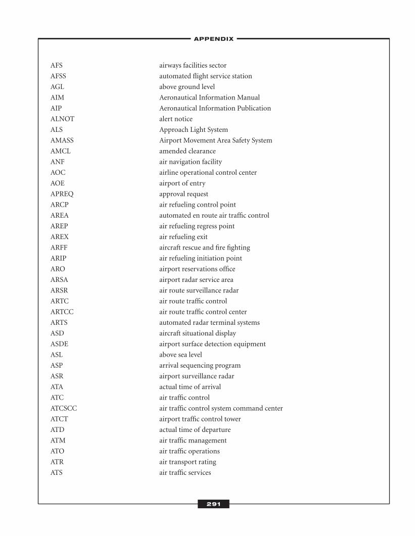
–APPENDIX–
291
AFS airways facilities sector
AFSS automated flight service station
AGL above ground level
AIM Aeronautical Information Manual
AIP Aeronautical Information Publication
ALNOT alert notice
ALS Approach Light System
AMASS Airport Movement Area Safety System
AMCL amended clearance
ANF air navigation facility
AOC airline operational control center
AOE airport of entry
APREQ approval request
ARCP air refueling control point
AREA automated en route air traffic control
AREP air refueling regress point
AREX air refueling exit
ARFF aircraft rescue and fire fighting
ARIP air refueling initiation point
ARO airport reservations office
ARSA airport radar service area
ARSR air route surveillance radar
ARTC air route traffic control
ARTCC air route traffic control center
ARTS automated radar terminal systems
ASD aircraft situational display
ASDE airport surface detection equipment
ASL above sea level
ASP arrival sequencing program
ASR airport surveillance radar
ATA actual time of arrival
ATC air traffic control
ATCSCC air traffic control system command center
ATCT airport traffic control tower
ATD actual time of departure
ATM air traffic management
ATO air traffic operations
ATR air transport rating
ATS air traffic services
ATC_2008b:Layout 1 11/24/08 1:19 PM Page 291
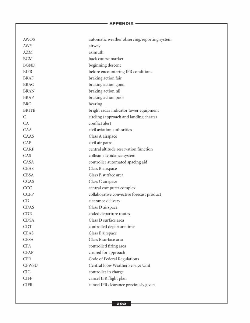
–APPENDIX–
292
AWOS automatic weather observing/reporting system
AWY airway
AZM azimuth
BCM back course marker
BGND beginning descent
BIFR before encountering IFR conditions
BRAF braking action fair
BRAG braking action good
BRAN braking action nil
BRAP braking action poor
BRG bearing
BRITE bright radar indicator tower equipment
C circling (approach and landing charts)
CA conflict alert
CAA civil aviation authorities
CAAS Class A airspace
CAP civil air patrol
CARF central altitude reservation function
CAS collision avoidance system
CASA controller automated spacing aid
CBAS Class B airspace
CBSA Class B surface area
CCAS Class C airspace
CCC central computer complex
CCFP collaborative convective forecast product
CD clearance delivery
CDAS Class D airspace
CDR coded departure routes
CDSA Class D surface area
CDT controlled departure time
CEAS Class E airspace
CESA Class E surface area
CFA controlled firing area
CFAP cleared for approach
CFR Code of Federal Regulations
CFWSU Central Flow Weather Service Unit
CIC controller in charge
CIFP cancel IFR flight plan
CIFR cancel IFR clearance previously given
ATC_2008b:Layout 1 11/24/08 1:19 PM Page 292
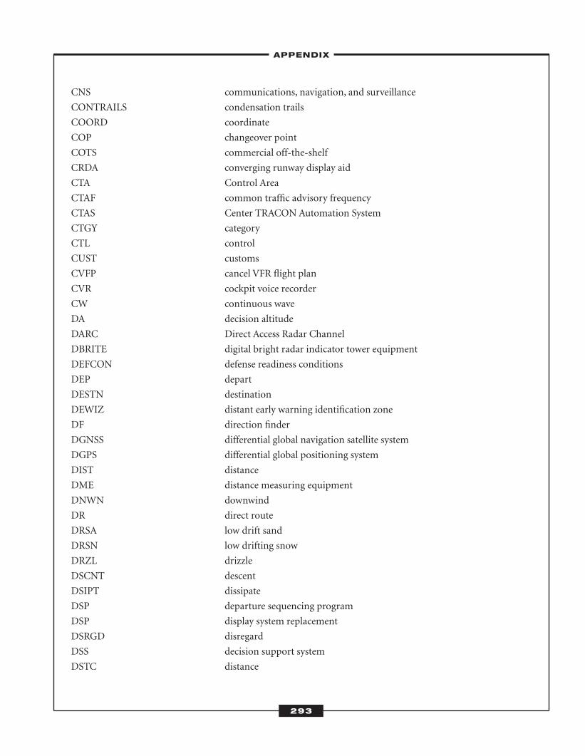
–APPENDIX–
293
CNS communications, navigation, and surveillance
CONTRAILS condensation trails
COORD coordinate
COP changeover point
COTS commercial off-the-shelf
CRDA converging runway display aid
CTA Control Area
CTAF common traffic advisory frequency
CTAS Center TRACON Automation System
CTGY category
CTL control
CUST customs
CVFP cancel VFR flight plan
CVR cockpit voice recorder
CW continuous wave
DA decision altitude
DARC Direct Access Radar Channel
DBRITE digital bright radar indicator tower equipment
DEFCON defense readiness conditions
DEP depart
DESTN destination
DEWIZ distant early warning identification zone
DF direction finder
DGNSS differential global navigation satellite system
DGPS differential global positioning system
DIST distance
DME distance measuring equipment
DNWN downwind
DR direct route
DRSA low drift sand
DRSN low drifting snow
DRZL drizzle
DSCNT descent
DSIPT dissipate
DSP departure sequencing program
DSP display system replacement
DSRGD disregard
DSS decision support system
DSTC distance
ATC_2008b:Layout 1 11/24/08 1:19 PM Page 293
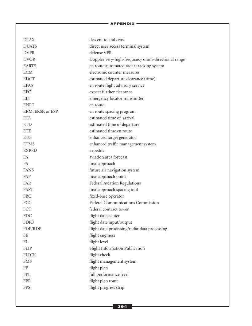
–APPENDIX–
294
DTAX descent to and cross
DUATS direct user access terminal system
DVFR defense VFR
DVOR Doppler very-high-frequency omni-directional range
EARTS en route automated radar tracking system
ECM electronic counter measures
EDCT estimated departure clearance (time)
EFAS en route flight advisory service
EFC expect further clearance
ELT emergency locator transmitter
ENRT en route
ERM, ERSP, or ESP en route spacing program
ETA estimated time of arrival
ETD estimated time of departure
ETE estimated time en route
ETG enhanced target generator
ETMS enhanced traffic management system
EXPED expedite
FA aviation area forecast
FA final approach
FANS future air navigation system
FAP final approach point
FAR Federal Aviation Regulations
FAST final approach spacing tool
FBO fixed-base operator
FCC Federal Communications Commission
FCT federal contract tower
FDC flight data center
FDIO flight date input/output
FDP/RDP flight data processing/radar data processing
FE flight engineer
FL flight level
FLIP Flight Information Publication
FLTCK flight check
FMS flight management system
FP flight plan
FPL full performance level
FPR flight plan route
FPS flight progress strip
ATC_2008b:Layout 1 11/24/08 1:19 PM Page 294
–APPENDIX–
295
FRC full route clearance
FRH fly runway heading
FROPA frontal passage
FSL full stop landing
FSS flight service station
FZ super cooled/freezing
FZRANO freezing rain sensor not available
G/A ground to air
G/A/G ground to air and air to ground
GA general aviation
GC ground control
GCA ground control approach
GCI ground control intercept
GDP ground delay program
GENOT General Notices Issued by Washington Headquarters
GLONASS global orbiting navigational satellite system
GNSS Global Navigation Satellite System
GPS Global Positioning System
GRDL gradual
GWT gross weight
HAA height above airport
HAT height above touchdown
HCS host computer system
HDG heading
HDTA high-density traffic airport
HF high frequency
HFR hold for release
HIRL high-intensity runway lights
HIWA Hazardous In-flight Weather Advisory Service
HP holding pattern
HUD heads-up display
IAF initial approach fix
IAP instrument approach procedure
IAS indicated air speed
IATA International Air Transport Association
IBND inbound
ICAO International Civil Aviation Organization
IF intermediate fix
IFIM International Flight Information Manual
ATC_2008b:Layout 1 11/24/08 1:19 PM Page 295
–APPENDIX–
296
IFR Instrument Flight Rules
IFSS International Flight Service Station
ILS Instrument Landing System
IM inner marker
IMC instrument meteorological conditions
INBD inbound
INS Inertial Navigation System
INSTBY instability
INT intersection
INTCP intercept
INTXN intersection
INVOF in the vicinity of
IP initial point
IPT integrated product team
IR IFR Military Training Route
ITC in-trail climb
ITD in-trail descent
JATO jet-assisted take-off
J-BAR jet runway barrier
JPDO Joint Programs and Development Office
JSS Joint Surveillance System
LA low approach
LAAS Local-Area Augmentation System
LAB laboratory
LAHSO land and old short operations
LAN local area network
LAT latitude
LAWRS limited aviation weather reporting station
LC local control
LDA localizer-type directional aid
LDG landing
LDIN lead-in lighting system
LIRL low-intensity runway edge lights
LLWAS Low-level Wind Shear Alert System
LLWS low-level wind shear
LMM compass locator at ILS middle marker
LO CIGS low ceilings
LOM compass locator at ILS outer marker
LOP line-of-position
ATC_2008b:Layout 1 11/24/08 1:19 PM Page 296
–APPENDIX–
297
LORAN long-range navigation
LP linear polarization
LRR long-range radar
LT turn left after take-off
M Match number (speed ratio to speed of sound)
MAA maximum authorized (IFR) altitude
MALS Medium-intensity Approach Lighting System
MALSF Medium-intensity Approach Lighting System with sequenced flashers
MALSR Medium-intensity Approach Lighting System with runway alignment
indicator lights
MB marker beacon
MCA minimum crossing altitude
MDA minimum descent altitude
MEA minimum en route altitude
METAR aviation routine weather report
MFOB minimum fuel on board
MHA minimum holding alcohol
MHDF medium-and high-frequency direction-finding station (same location)
MIRL medium-intensity runway edge lights
MNPS minimum navigation performance specification
MNPSA minimum navigation performance specification airspace
MOCA minimum obstruction clearance altitude
MODE C altitude-reporting mode of secondary radar
MRA minimum reception altitude
MSA minimum safe altitude
MSAW minimum safe altitude warning
MSL mean sea level
MT mountain
MTCA minimum terrain clearance altitude
MTD moving target detection
MTI moving target indicator
MTR Military Training Route
MULTI-TAX many aircraft trying to taxi at once, creating congestion
MVFR maintain VFR
NAATS National Association of Air Traffic Control Specialists
NAFEC National Aviation Facilities Experimental Center
NAR North American route
NASP national airport system plan
NAT North Atlantic track
ATC_2008b:Layout 1 11/24/08 1:19 PM Page 297
–APPENDIX–
298
NATCA National Traffic Controllers Association
NATS National Air Traffic Service
NAVAID navigational aid
NDB non-directional radio beacon
NEXRAD Next-Generation Weather Radar
NFDC National Flight Data Center
NM nautical miles
NMC National Meteorological Center
NOPT no procedure turn required
NOTAM notice to airmen
NRP North American Route Program
NTAP Notices To Airmen publication
NTZ no transgression zone
NWS National Weather Service
OA overhead approach
OBND outbound
OBST obstacle
OBSTN obstruction
OC on course
OCA obstacle clearance altitude
ODALS Omni-directional Approach Lighting System
OAPS oceanic display and planning system
OFSHR offshore
OG on ground
OHD overhead
OJT on-the-job training
OM outer marker
OMB U.S. Office of Management and Budget
ORD Operational Readiness Demonstration
OSHA Occupational Safety and Health Administration
OT on time
OTLK outlook
OTP VFR conditions-on-top
P/CG Pilot Controller Glossary
P6SM visibility greater than 6 statue miles (TAF only)
PAPI precision approach path indicator
PAR precision approach radar
PCL pilot-controlled lighting
PCS permanent change of station
ATC_2008b:Layout 1 11/24/08 1:19 PM Page 298
–APPENDIX–
299
PDAR preferential arrival/departure route (Stage A)
PDC pre-departure clearance
PDR preferential departure route (Stage A)
PIC pilot in command
PIREP pilot weather report
PLASI pulsating visual approach slope indicators
PPI plan position indicator
PPINA radar weather report not available (or omitted for a reason different than
those otherwise stated.)
PPINE radar weather report no echoes observed.
PPINO radar weather report equipment inoperative due to breakdown
PPIOK radar weather report equipment operation resumed
PPIOM radar weather report equipment operation resumed
PPR prior permission required
PRBLTY probability
PRES pressure
PRESFR pressure falling rapidly
PREV previous
PRM precision runway monitor
PSR primary surveillance radar
PT procedure turn
PTCHY patchy
PUBL publish
PVD plan view display
PWI proximity warning indicator
PWINO precipitation identifier information not available (weather reports only)
QFE atmospheric pressure at airport elevation
QFLOW quota flow control procedures
QNH altimeter subscale setting to obtain elevation when on the ground
RAGF remote air-ground facility
RAIM receiver autonomous integrity monitoring
RAPCON radar approach control
RAR runway acceptance rate
RBDE radar bright display equipment
RBN radio beacon
RCC rescue coordination center
RCK radio check
RCL runway centerline
RCLL runway centerline lights
ATC_2008b:Layout 1 11/24/08 1:19 PM Page 299
–APPENDIX–
300
RCO remote communication outlet
RCR runway condition reading
RCVNO receiving capability out
RDL radial
REIL runway end identifier lights
RENOT Regional Notices Issued by Washington Headquarters
RF radio frequency
RFI radio frequency interference
RHI range height indicator
RHINO radar echo height information not available
RIF reduction in force
RITC request in trail climb
RITD request in trail descent
RL report immediately upon leaving
RMM remote maintenance monitoring
RNAV Required Navigation Performance
ROC rate of climb
ROD rate of descent
ROTG rotating
RPM rotation per minute
RPV remotely piloted vehicle
RT right turn after take-off
RTE route
RTR remote transmitter/receiver
RVR runway visual range
RVRNO RVR not available
RVSM Reduced Vertical Separation Minimum
RVV runway visibility value
RVVNO RVV not available
RWY or RY runway
SALS Short Approach Lighting System
SALSF Short Approach Lighting System with sequenced flashing lights
SCATANA security control of air traffic and air navigation aids
SCT scattered
SCTR sector
SCTY security
SDBY standby
SDF simplified directional facility
SECT sector
ATC_2008b:Layout 1 11/24/08 1:19 PM Page 300
–APPENDIX–
301
SEPN separation
SFL sequence flashing lights
SHF super-high frequency
SI straight-in approach
SIAP standard instrument approach procedure
SID Standard Instrument Departures
SIGMET significant meteorological information
SIGWX significant weather
SIMUL simultaneous
SKC sky clear
SKED schedule
SM statute mile
SMA surface movement advisor
SOP standard operating practice
SPD speed
SPEC specification
SPECI non-routine aviation selected special weather report
SPO strategic plan of operation
SQDN squadron
SRND surround
SRY secondary
SSALF Simplified Short Approach Lighting System with sequenced flashers
SSALS Simplified Short Approach Lighting System
SSB single sideband
SSNO request no SIDS or STARS
SSR secondary surveillance radar
ST straight in approach
STAR standard terminal arrival route
STARS standard terminal automation replacement system
STMP special traffic management program
STOL short take-off landing
STWY stopway
SUA special-use airspace
SUB substitute
SUSP suspend
SVC service
SVFR special VFR
SVRWX severe weather
SWAP severe weather avoidance plan
ATC_2008b:Layout 1 11/24/08 1:19 PM Page 301
–APPENDIX–
302
SWAP severe weather avoidance procedures
SYNS synopsis
TACAN Tactical Air Navigation
TAF terminal aerodrome forecast
TAS true air speed
TCAS Traffic Alert and Collision Avoidance System
TCCC tower control computer complex
TCH threshold crossing height
TCP transfer of control point
TCVR transceiver
TDWR terminal Doppler weather radar
TDY temporary duty
TEC tower en route control
TERPS terminal instrument approach procedure
TFC traffic
TFM traffic flow management
TFR temporary flight restriction
THLD threshold
TMA traffic management advisor
TMC traffic management coordinator
TMI traffic management initiatives
TMS traffic management system
TMU traffic management unit
TOG take-off gross weight
TR VFR low-altitude training routes
TRACON terminal radar approach control
TS thunderstorm
TSA Transportation Security Administration
TSD traffic situation display
TSFR transfer
TSGR thunderstorm with hail
TSGS thunderstorm with small hail
TSO technical standard order
TSPL thunderstorm with ice pellets
TSRA thunderstorm with rain
TSSA thunderstorm with dust storm or sandstorm
TSSN thunderstorm with snow
TSTM thunderstorm
TSTMS thunderstorms
ATC_2008b:Layout 1 11/24/08 1:19 PM Page 302
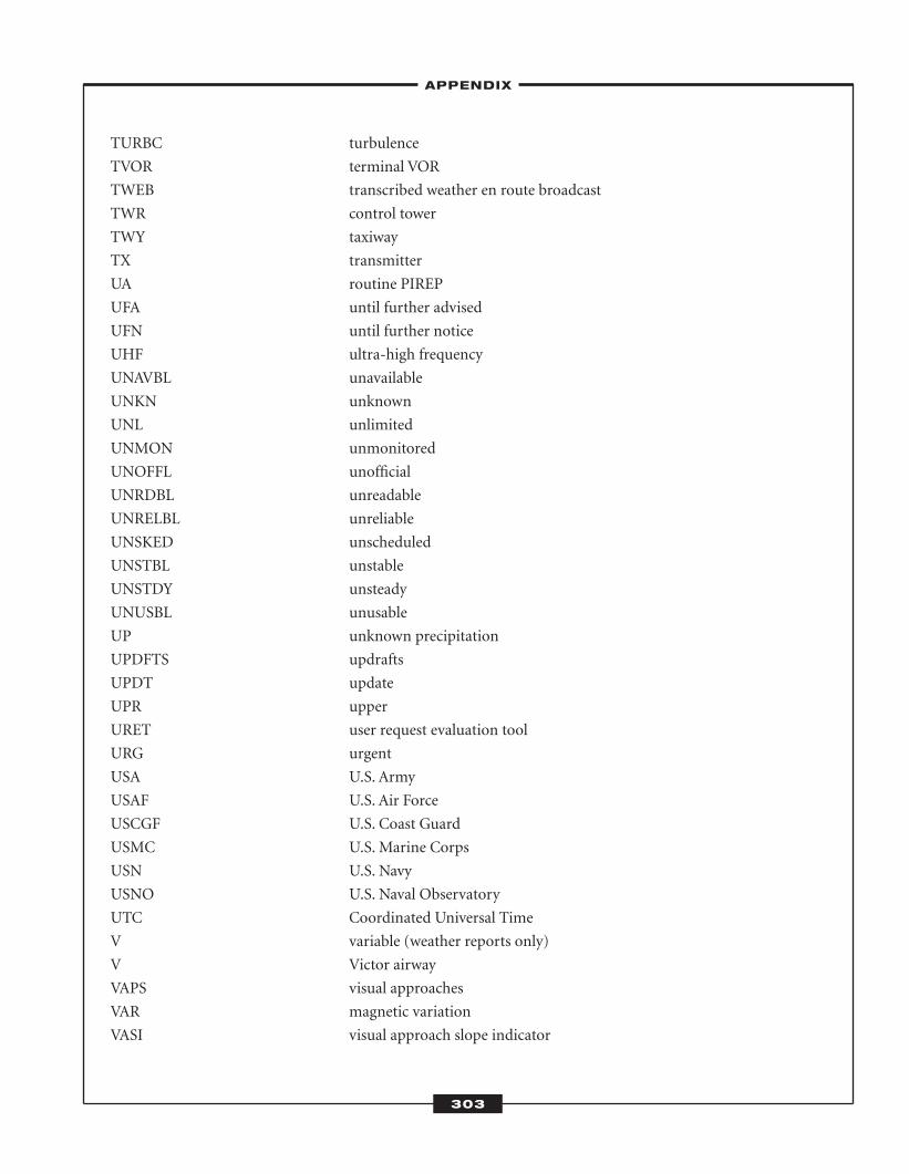
–APPENDIX–
303
TURBC turbulence
TVOR terminal VOR
TWEB transcribed weather en route broadcast
TWR control tower
TWY taxiway
TX transmitter
UA routine PIREP
UFA until further advised
UFN until further notice
UHF ultra-high frequency
UNAVBL unavailable
UNKN unknown
UNL unlimited
UNMON unmonitored
UNOFFL unofficial
UNRDBL unreadable
UNRELBL unreliable
UNSKED unscheduled
UNSTBL unstable
UNSTDY unsteady
UNUSBL unusable
UP unknown precipitation
UPDFTS updrafts
UPDT update
UPR upper
URET user request evaluation tool
URG urgent
USA U.S. Army
USAF U.S. Air Force
USCGF U.S. Coast Guard
USMC U.S. Marine Corps
USN U.S. Navy
USNO U.S. Naval Observatory
UTC Coordinated Universal Time
V variable (weather reports only)
V Victor airway
VAPS visual approaches
VAR magnetic variation
VASI visual approach slope indicator
ATC_2008b:Layout 1 11/24/08 1:19 PM Page 303
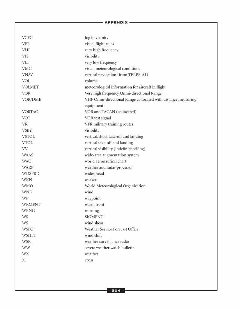
–APPENDIX–
304
VCFG fog in vicinity
VFR visual flight rules
VHF very high frequency
VIS visibility
VLF very low frequency
VMC visual meteorological conditions
VNAV vertical navigation (from TERPS-A1)
VOL volume
VOLMET meteorological information for aircraft in flight
VOR Very high frequency Omni-directional Range
VOR/DME VHF Omni-directional Range collocated with distance measuring
equipment
VORTAC VOR and TACAN (collocated)
VOT VOR test signal
VR VFR military training routes
VSBY visibility
VSTOL vertical/short take-off and landing
VTOL vertical take-off and landing
VV vertical visibility (indefinite ceiling)
WAAS wide-area augmentation system
WAC world aeronautical chart
WARP weather and radar processor
WDSPRD widespread
WKN weaken
WMO World Meteorological Organization
WND wind
WP waypoint
WRMFNT warm front
WRNG warning
WS SIGMENT
WS wind shear
WSFO Weather Service Forecast Office
WSHFT wind shift
WSR weather surveillance radar
WW severe weather watch bulletin
WX weather
X cross
ATC_2008b:Layout 1 11/24/08 1:19 PM Page 304
305
abbreviated IFR flight plans. an authorization by ATC requiring pilots to submit only that information needed
for the purpose of ATC. It includes only a small portion of the usual IFR flight plan information. In certain
instances, this may be only aircraft identification, location, and pilot request. Other information may be requested
if needed by ATC for separation/control purposes. Abbreviated IFR flight plans are frequently used by aircraft
that are airborne and desire an instrument approach or by aircraft that are on the ground and desire a climb to
VFR-on-top.
abeam. an aircraft is “abeam” a point or an object when that point or object is about 90 degrees to the right or
left of the aircraft track. Abeam indicates a general position rather than a precise point.
accelerate-stop distance available. the length of the takeoff run available plus the length of the stopway if
provided.
acrobatic flight. an intentional maneuver involving an abrupt change in an aircraft’s attitude, an abnormal atti-
tude, or abnormal acceleration not necessary for normal flight.
additional services. advisory information provided by ATC that includes, but is not limited to, the following:
� traffic advisories
� vectors, when requested by the pilot, to assist aircraft receiving traffic advisories to avoid observed
traffic
� altitude deviation information of 300 feet or more from an assigned altitude as observed on a veri-
fied (reading correctly) automatic altitude readout (Mode C)
� advisories that traffic is no longer a factor
� weather and chaff information
� weather assistance
Glossary
ATC_2008b:Layout 1 11/24/08 1:19 PM Page 305
–GLOSSARY–
306
� bird activity information
� holding pattern surveillance
administrator. FAA administrator or any person to whom he or she has delegated authority to in the matter
concerned.
advisory. advice and information provided to assist pilots in the safe conduct of flight and aircraft movement.
advisory service. advice and information provided by a facility to assist pilots in the safe conduct of flight and
aircraft movement.
aeronautical chart. a map used in air navigation displaying part or all of the following: topographic features, haz-
ards and obstructions, navigation aids, navigation routes, designated airspace, and airports. Commonly used aero-
nautical charts include (1) sectional charts; (2) VFR terminal area charts; (3) world aeronautical charts (WACs);
(4) en route low altitude charts; (5) en route high altitude charts; (6) instrument approach procedures (IAP) charts;
(7) instrument departure procedure (DP) charts; (8) standard terminal arrival (STAR) charts; (9) airport taxi
charts.
Aeronautical Information Manual (AIM). a primary FAA publication designed to instruct pilots and controllers
about operation in the NAS. It provides basic flight information, ATC procedures, and general instructional infor-
mation concerning health, medical facts, factors affecting flight safety, accident and hazard reporting, and types
of aeronautical charts and their use.
Aeronautical Information Publication (AIP). a publication issued by or with the authority of a state and con-
taining aeronautical information of a lasting character essential to air navigation.
air carrier district office. an FAA field office serving an assigned geographical area, staffed with flight standards
personnel serving the aviation industry and the general public on matters related to the certification and opera-
tion of scheduled air carriers and other large aircraft operations.
aircraft attitude. a term used to describe the orientation of an aircraft with respect to the horizon.
air defense identification zone (ADIZ). the area of airspace over land or water, extending upward from the sur-
face, within which the ready identification, location, and control of aircraft are required in the interest of national
security. This includes
� Domestic Air Defense Identification Zone—an ADIZ within the United States and along an inter-
national boundary.
� Coastal Air Defense Identification Zone—an ADIZ over the coastal waters of the United States.
� Distant Early Warning Identification Zone (DEWIZ)—an ADIZ over the coastal waters of Alaska.
� Land-Based Air Defense Identification Zone—an ADIZ over U.S. metropolitan areas, which is acti-
vated and deactivated as needed, with dimensions, activation dates, and other relevant information
disseminated via NOTAM.
air navigation facility. any facility used, available for use, or designed for use in air navigation, including land-
ing areas, lights, any apparatus or equipment for disseminating weather information, for signaling, for radio-direc-
ATC_2008b:Layout 1 11/24/08 1:19 PM Page 306
–GLOSSARY–
307
tional finding, or for radio or other electrical communication, and any other structure or mechanism having a
similar purpose for guiding or controlling flight in the air or the landing and takeoff of aircraft.
air route surveillance radar (ARSR). ARTCC radar used primarily to detect and display an aircraft’s position while
en route between terminal areas. The ARSR enables controllers to provide radar ATC service when aircraft are
within the ARSR coverage. In some instances, ARSR may enable an ARTCC to provide terminal radar services
similar to but usually more limited than those provided by a radar approach control.
air route traffic control center (ARTCC). a facility established to provide ATC service to aircraft operating on
IFR flight plans within controlled airspace and principally during the en route phase of flight. When equipment
capabilities and controller workload permit, certain advisory/assistance services may be provided to VFR aircraft.
air traffic. aircraft operating in the air or on an airport surface, exclusive of loading ramps and parking areas.
air traffic clearance. an authorization by ATC for an aircraft to proceed under specified traffic conditions within
controlled airspace. The pilot in command of an aircraft may not deviate from the provisions of a VFR or IFR
air traffic clearance except in an emergency or unless an amended clearance has been obtained. Additionally, the
pilot may request a different clearance from that issued by ATC if information available to the pilot makes another
course of action more practical or if aircraft equipment limitations or company procedures forbid compliance
with the clearance issued. Pilots may also request clarification or amendment, as appropriate, any time a clear-
ance is not fully understood, or considered unacceptable because of safety of flight. Controllers should, in such
instances and to the extent of operational practicality and safety, honor the pilot’s request.
air traffic control (ATC). a service operated by appropriate authority to promote the safe, orderly, and expedi-
tious flow of air traffic.
air traffic control (ATC) clearance. authorization of an aircraft to proceed under conditions specified by an ATC
unit. For convenience, ATC clearance is frequently abbreviated as “clearance,” and the abbreviated term “
clearance” may be prefixed by the words taxi, takeoff, departure, en route, approach, or landing to indicate the par-
ticular portion of flight to which the ATC clearance relates.
air traffic control system command center (ATCSCC). air traffic tactical operations facility responsible for mon-
itoring and managing the flow of air traffic throughout the NAS; the goal is to direct air traffic in a safe and orderly
way and to minimize delays. The following functions are located at the ATCSCC:
� Central Altitude Reservation Function (CARF)—responsible for coordinating, planning, and
approving special user requirements under the Altitude Reservation (ALTRV) concept.
� Airport Reservation Office (ARO)—responsible for approving IFR flights at designated high-den-
sity traffic airports (John F. Kennedy, LaGuardia, and Ronald Reagan Washington National) during
specified hours.
� U.S. Notice to Airmen (NOTAM) Office—responsible for collecting, maintaining, and distributing
NOTAMs for the U.S. civilian and military, as well as international, aviation communities.
� Weather Unit—monitors all aspects of weather for the United States that might affect aviation
including cloud cover, visibility, winds, precipitation, thunderstorms, icing, and turbulence. Pro-
ATC_2008b:Layout 1 11/24/08 1:19 PM Page 307
–GLOSSARY–
308
vides forecasts based on observations and discussions with meteorologists from various National
Weather Service (NWS) offices, FAA facilities, airlines, and private weather services.
air traffic service. a generic term referring to flight information service, alerting service, air traffic advisory serv-
ice, and ATC service including area control service, approach control service, and airport control service.
air traffic service (ATS) routes. a generic term that includes “VOR federal airways,” “colored federal airways,” “jet
routes,” and “RNAV routes.” The term “ATS route” does not replace these more familiar route names, but serves
only as an overall title when listing the types of routes that comprise the U.S. route structure.
aircraft approach category. a grouping of aircraft based on a speed of 1.3 times the stall speed in the landing con-
figuration at maximum gross landing weight. An aircraft must fit in only one category. If it is necessary to maneu-
ver at speeds in excess of the upper limit of a speed range for a category, the minimums for the category for that
speed must be used. For example, an aircraft that falls into Category A, but is circling to land at a speed in excess
of 91 knots, must use the approach Category B minimums when circling to land. The categories are as follows:
Category A (speed less than 91 knots); Category B (speed 91 knots or more but less than 121 knots); Category C
(speed 121 knots or more but less than 141 knots); Category D (speed 141 knots or more but less than 166 knots);
and Category E (speed 166 knots or more).
aircraft classes. for the purposes of wake turbulence separation minima (minimum), ATC classifies aircraft as:
� heavy—aircraft capable of takeoff weights of more than 255,000 pounds whether or not they are
operating at this weight during a particular phase of flight
� large—aircraft of more than 41,000 pounds, maximum certificated takeoff weight, up to 255,000
pounds
� small—aircraft of 41,000 pounds or less maximum certificated takeoff weight
aircraft conflict. predicted conflict, within URET, of two aircraft, or between aircraft and airspace. A red alert is
used for conflicts when the predicted minimum separation is 5 NM or less. A yellow alert is used when the pre-
dicted minimum separation is between 5 and approximately 12 NM. A blue alert is used for conflicts between an
aircraft and predefined airspace.
AIRMET. in-flight weather advisories issued only to amend the area forecast concerning weather phenomena that
are of operational interest to all aircraft and potentially hazardous to aircraft having limited capability because
of lack of equipment, instrumentation, or pilot qualifications. AIRMETs concern weather of less severity than that
covered by SIGMETs or Convective SIGMETs. AIRMETs cover moderate icing, moderate turbulence, sustained
winds of 30 knots or more at the surface, widespread areas of ceilings less than 1,000 feet and/or visibility less
than 3 miles, and extensive mountain obscurement.
airport. an area on land or water that is used or intended to be used for the landing and takeoff of aircraft and
includes its buildings and facilities.
airport advisory area. the area within 10 miles of an airport without a control tower or where the tower is not
in operation and on which a FSS is located.
ATC_2008b:Layout 1 11/24/08 1:19 PM Page 308
–GLOSSARY–
309
airport arrival rate (AAR). a dynamic input parameter specifying the number of arriving aircraft that an airport
or airspace can accept from the ARTCC per hour. AAR is used to calculate the desired interval between succes-
sive arrival aircraft.
airport departure rate (ADR). a dynamic parameter specifying the number of aircraft that can depart an airport
and the airspace can accept per hour.
airport elevation. the highest point of an airport’s usable runways measured in feet from MSL.
Airport Facility/Directory. a publication designed primarily as a pilot’s operational manual containing all air-
ports, seaplane bases, and heliports open to the public including communications data, navigational facilities, and
certain special notices and procedures. This publication is issued in seven volumes according to geographical area.
airport lighting. various lighting aids that may be installed on an airport, including
� Approach Light System (ALS)—an airport lighting facility that provides visual guidance to landing
aircraft by radiating light beams in a directional pattern by which the pilot aligns the aircraft with
the extended centerline of the runway on his or her final approach for landing. Condenser-dis-
charge sequential flashing lights/sequenced flashing lights may be installed in conjunction with the
ALS at some airports. Types of ALS include
1. ALSF-1—ALS with sequenced flashing lights in ILS Cat-I configuration.
2. ALSF-2—ALS with sequenced flashing lights in ILS Cat-II configuration. The ALSF-2 may
operate as an SSALR when weather conditions permit.
3. SSALF—simplified short ALS with sequenced flashing lights.
4. SSALR—simplified short ALS with runway-alignment indicator lights.
5. MALSF—medium-intensity ALS with sequenced flashing lights.
6. MALSR—medium-intensity ALS system with runway-alignment indicator lights.
7. LDIN—lead-in-light system; consists of one or more series of flashing lights installed at or near
ground level that provides positive visual guidance along an approach path, either curved or
straight, where special problems exist with hazardous terrain, obstructions, or noise abatement
procedures.
8. RAIL—runway-alignment indicator lights; sequenced flashing lights installed only in combina-
tion with other light systems.
9. ODALS—omnidirectional ALS consisting of seven omnidirectional flashing lights located in
the approach area of a nonprecision runway. Five lights are located on the runway centerline
extended with the first light located 300 feet from the threshold and extending at equal inter-
vals up to 1,500 feet from the threshold. The other two lights are located, one on each side of
the runway threshold, at a lateral distance of 40 feet from the runway edge, or 75 feet from the
runway edge when installed on a runway equipped with a visual approach slope indicator
(VASI).
ATC_2008b:Layout 1 11/24/08 1:19 PM Page 309
–GLOSSARY–
310
� runway lights/runway-edge lights—lights having a prescribed angle of emission used to define the
lateral limits of a runway. Runway lights are uniformly spaced at intervals of approximately 200
feet, and the intensity may be controlled or preset.
� touchdown zone lighting—two rows of transverse light bars located symmetrically about the run-
way centerline normally at 100-foot intervals. The basic system extends 3,000 feet along the run-
way.
� runway centerline lighting—flush centerline lights spaced at 50-foot intervals beginning 75 feet
from the landing threshold and extending to within 75 feet of the opposite end of the runway.
� threshold lights—fixed green lights arranged symmetrically left and right of the runway centerline,
identifying the runway threshold.
� runway-end identifier lights (REIL)—two synchronized flashing lights, one on each side of the
runway threshold, that provide rapid and positive identification of the approach end of a particular
runway.
� visual approach slope indicator (VASI)—an airport lighting facility providing vertical visual
approach slope guidance to aircraft during approach to landing by radiating a directional pattern
of high-intensity red and white focused light beams, which indicate to the pilot that he or she is “on
path.” If the pilot sees white/white flashing lights, he or she is “above path,” and if the pilot sees
red/red flashing lights, the pilot is “below path.” Some airports serving large aircraft have three-bar
VASIs that provide two visual guide paths to the same runway.
� precision approach path indicator (PAPI)—an airport lighting facility, similar to VASI, providing
vertical approach slope guidance to aircraft during approach to landing. PAPIs consist of a single
row of either two or four lights, normally installed on the left side of the runway, and have an effec-
tive visual range of about 5 miles during the day and up to 20 miles at night. PAPIs radiate a direc-
tional pattern of high-intensity red and white focused light beams, which indicate that the pilot is
“on path” if the pilot sees an equal number of white lights and red lights, with white to the left of
the red; “above path” if the pilot sees more white lights than red lights; and “below path” if the pilot
sees more red lights than white lights.
� boundary lights—lights defining the perimeter of an airport or a landing area.
airport marking aids. markings used on runway and taxiway surfaces to identify a specific runway, runway thresh-
old, centerline, or hold line. A runway should be marked in accordance with its present usage such visual, non-
precision instrument, or precision instrument.
airport reference point (ARP). the approximate geometric center of all usable runway surfaces.
airport reservation office. the office responsible for monitoring the operation of the high-density rule. Receives
and processes requests for IFR-operations at high-density traffic airports.
ATC_2008b:Layout 1 11/24/08 1:19 PM Page 310
–GLOSSARY–
311
airport rotating beacon. a NAVAID in operation at many airports. At civil airports, alternating white and green
flashes indicate the location of the airport. At military airports, the beacons flash alternately white and green, but
are differentiated from civil beacons by dual-peaked (two quick) white flashes between the green flashes.
airport surveillance radar (ASR). approach control radar used to detect and display an aircraft’s position in the
terminal area. ASR provides range and azimuth information but does not provide elevation data. Coverage of ASR
can extend up to 60 miles.
airport traffic control (ATC) service. a service provided by a control tower for aircraft operating on the move-
ment area and in the vicinity of an airport.
airspace hierarchy.within the airspace classes, there is a hierarchy and, in the event of an overlap of airspace: Class
A preempts Class B, Class B preempts Class C, Class C preempts Class D, Class D preempts Class E, and Class E
preempts Class G.
airspeed. the speed of an aircraft relative to its surrounding air mass. The unqualified term “airspeed” means one
of the following:
� indicated airspeed—the speed shown on the aircraft airspeed indicator. This is the speed used in
pilot/controller communications under the general term “airspeed.”
� true airspeed—the airspeed of an aircraft relative to undisturbed air. Used primarily in flight plan-
ning and en route portion of flight. When used in pilot/controller communications, it is referred to
as “true airspeed” and not shortened to “airspeed.”
airstart. the starting of an aircraft engine while the aircraft is airborne, preceded by engine shutdown during train-
ing flights or by actual engine failure.
airway. a control area or portion thereof established in the form of corridor equipped with radio navigational
aids.
airway beacon. used to mark airway segments in remote mountain areas. The light flashes Morse Code to iden-
tify the beacon site.
alternate airport. an airport at which an aircraft may land if a landing at the intended airport becomes
inadvisable.
altitude. the vertical distance of a level, a point, or an object considered as a point, measured from MSL.
altitude readout. An aircraft’s altitude, transmitted via the Mode C transponder feature, that is visually displayed
in 100-foot increments on a radar scope having readout capability.
altitude reservation (ALTRV). airspace utilization under prescribed conditions normally employed for the mass
movement of aircraft or other special user requirements that cannot otherwise be accomplished. ALTRVs are
approved by the appropriate FAA facility.
altitude restriction. an altitude or altitudes, stated in the order flown, that are to be maintained until reaching a
specific point or time. Altitude restrictions may be issued by ATC due to traffic, terrain, or other airspace con-
siderations.
approach control facility. a terminal ATC facility that provides approach control service in a terminal area.
ATC_2008b:Layout 1 11/24/08 1:19 PM Page 311
–GLOSSARY–
312
approach control service. ATC service provided by an approach control facility for arriving and departing
VFR/IFR aircraft and, on occasion, en route aircraft. At some airports not served by an approach control facility,
the ARTCC provides limited approach control service.
approach gate. an imaginary point used within ATC as a basis for vectoring aircraft to the final approach course.
The gate will be established along the final approach course 1 mile from the final approach fix on the side away
from the airport and will be no closer than 5 miles from the landing threshold.
approach sequence. the order in which aircraft are positioned while on approach or awaiting approach clearance.
approach speed. the recommended speed contained in aircraft manuals used by pilots when making an approach
to landing. This speed varies for different segments of an approach as well as for aircraft weight and configura-
tion.
appropriate ATS authority. the relevant authority designated by the state responsible for providing air traffic serv-
ices in an airspace. In the United States, the “appropriate ATS authority” is the program director for air traffic plan-
ning and procedures, ATP-1.
apron. a defined area on an airport, a heliport, or an aerodome intended to accommodate aircraft for purposes
of loading or unloading passengers or cargo, refueling, parking, or maintenance. With regard to seaplanes, a ramp
is used for access to the apron from the water.
area navigation (RNAV). provides enhanced navigational capability to the pilot. RNAV equipment can compute
the airplane position, actual track, and ground speed and then provide meaningful information relative to a route
of flight selected by the pilot. Typical equipment will provide the pilot with distance, time, bearing, and crosstrack
error relative to the selected “TO” or “active” waypoint and the selected route. RNAV systems include Doppler
radar, LORAN, LORAN-C, Global Positioning Systems (GPS), and Inertial Navigation Systems (INS).
Army Aviation Flight Information Bulletin. a bulletin that provides air operation data covering U.S. Army,
National Guard, and Army Reserve aviation activities.
arrival aircraft interval (AAI). an internally generated program in hundredths of minutes based upon the air-
port arrival rate (AAR). AAI is the desired optimum interval between successive arrival aircraft over the vertex.
arrival center. the ARTCC having jurisdiction for the impacted airport.
arrival delay. a parameter that specifies a period of time in which no aircraft will be metered for arrival at the
specified airport.
arrival sector. an operational control sector containing one or more meter fixes.
arrival sequencing program. the automated program designed to assist in sequencing aircraft destined for the
same airport.
arrival time. the time an aircraft touches down on arrival.
ATC assigned airspace. airspace of defined vertical/lateral limits, assigned by ATC, for the purpose of providing
air traffic segregation between the specified activities being conducted within the assigned airspace and other IFR
air traffic.
ATC_2008b:Layout 1 11/24/08 1:19 PM Page 312
–GLOSSARY–
313
ATC instructions. directives issued by ATC requiring a pilot to take a specific action such as “Turn left heading
two five zero,” “Go around,” “Clear the runway.”
ATC preferred route notification. URET notification to the appropriate controller of the need to determine if
an ATC preferred route needs to be applied, based on destination airport.
ATS route. a specified route designed for channeling the flow of traffic as necessary for the provision of air traf-
fic services. Note: The term “ATS route” is used to mean airway, advisory route, controlled or uncontrolled route,
and arrival or departure route.
Automated Radar Terminal Systems (ARTS). a generic term for several tracking systems included in the Termi-
nal Automation Systems (TAS). ARTS plus a Roman-numeral suffix denotes a specific system. A letter following
the Roman numeral indicates a major modification to that system.
� ARTS IIIA—the radar tracking and beacon tracking level (RT&BTL) of the modular, programma-
ble automated radar terminal system. ARTS IIIA detects, tracks, and predicts primary and second-
ary radar-derived aircraft targets. This more sophisticated computer-driven system upgrades the
existing ARTS III system by providing improved tracking, continuous data recording, and fail-soft
capabilities.
� common ARTS—includes ARTS IIE, ARTS IIIE; and ARTS IIIE with ACD (see DTAS), which com-
bines functionalities of the previous ARTS systems.
� programmable indicator data processor (PIDP)—the PIDP is a modification to the AN/TPX-42
interrogator system currently installed in fixed RAPCONs. The PIDP detects, tracks, and predicts
secondary radar aircraft targets. These are displayed by means of computer-generated symbols and
alphanumeric characters depicting flight identification, aircraft altitude, ground speed, and flight
plan data. Although primary radar targets are not tracked, they are displayed coincident with the
secondary radar targets as well as with the other symbols and alphanumerics. The system has the
capability of interfacing with ARTCCs.
automated weather system. any of the automated weather sensor platforms that collect weather data at airports
and disseminate the weather information via radio and/or landline. The systems currently consist of the Auto-
mated Surface Observing System (ASOS), Automated Weather Sensor System (AWSS), and Automated Weather
Observation System (AWOS).
automated UNICOM. provides completely automated weather, radio-check capability, and airport advisory infor-
mation on an automated UNICOM system. These systems offer a variety of features, typically selectable by micro-
phone clicks on the UNICOM frequency. Availability will be published in the Airport/Facility Directory and
approach charts.
automatic altitude reporting. that function of a transponder that responds to Mode C interrogations by trans-
mitting the aircraft’s altitude in 100-foot increments.
automatic dependent surveillance (ADS). a surveillance technique in which aircraft automatically provide, via
a data link, data derived from onboard navigation and position-fixing systems, including aircraft identification,
four-dimensional position, and additional data as appropriate.
ATC_2008b:Layout 1 11/24/08 1:19 PM Page 313
–GLOSSARY–
314
automatic dependent surveillance-broadcast (ADS-B). a surveillance system in which an aircraft or vehicle to
be detected is fitted with cooperative equipment in the form of a data-link transmitter. The aircraft or vehicle peri-
odically broadcasts its GPS-derived position and other information such as velocity over the data link, which is
received by a ground-based transmitter/receiver (transceiver) for processing and display at an ATC facility.
automatic dependent surveillance-contract (ADS-C). a data-link position reporting system, controlled by a
ground station, that establishes contracts with an aircraft’s avionics that occur automatically whenever specific
events occur or specific time intervals are reached.
automatic direction finder (ADF). an aircraft radio navigation system that senses and indicates the direction to
a L/MF nondirectional radio beacon (NDB) ground transmitter. Direction is indicated to the pilot as a magnetic
bearing or as a relative bearing to the longitudinal axis of the aircraft depending on the type of indicator installed
in the aircraft. In certain applications, such as military, ADF operations may be based on airborne and ground
transmitters in the VHF/UHF frequency spectrum.
automatic terminal information service. the continuous broadcast of recorded noncontrol information in
selected terminal areas. Its purpose is to improve controller effectiveness and to relieve frequency congestion by
automating the repetitive transmission of essential but routine information such as “Los Angeles information Alfa.
One three zero zero Coordinated Universal Time. Weather, measured ceiling two thousand overcast, visibility three,
haze, smoke, temperature seven one, dew point five seven, wind two five zero at five, altimeter two niner niner
six. I-L-S Runway Two Five Left approach in use, Runway Two Five Right closed, advise you have Alfa.”
automatic terminal information service. the provision of current, routine information to arriving and depart-
ing aircraft by means of continuous and repetitive broadcasts throughout the day or a specified portion of the
day.
available landing distance (ALD). the portion of a runway available for landing and roll-out for aircraft cleared
for land and hold short operations (LAHSO.) This distance is measured from the landing threshold to the hold
short point.
Aviation Weather Service. a service provided by the National Weather Service (NWS) and FAA that collects and
disseminates pertinent weather information for pilots, aircraft operators, and controllers. Available aviation
weather reports and forecasts are displayed at each NWS office and FSS.
azimuth (MLS). a magnetic bearing extending from an MLS navigation facility. Note: Azimuth bearings are
described as magnetic and are referred to as “azimuth” in radio-telephone communications.
back-taxi. a term used by controllers to taxi an aircraft on the runway opposite to the traffic flow. The aircraft
may be instructed to back-taxi to the beginning of the runway or at some point before reaching the runway end
to depart or exit the runway.
bearing. the horizontal direction to or from any point, usually measured clockwise from true north, magnetic
north, or some other reference point through 360 degrees.
blind speed. the rate of departure or closing of a target relative to the radar antenna at which cancellation of the
primary radar target by moving target indicator (MTI) circuits in the radar equipment causes a reduction or com-
plete loss of signal.
ATC_2008b:Layout 1 11/24/08 1:19 PM Page 314
–GLOSSARY–
315
blind spot. an area from which radio transmissions and/or radar echoes cannot be received. The term is also used
to describe portions of the airport not visible from the control tower.
braking action advisories. when tower controllers have received runway braking action reports that include the
terms “poor” or “nil,” or whenever weather conditions are conducive to deteriorating or rapidly changing run-
way braking conditions, the tower will include on the ATIS broadcast the statement, “BRAKING ACTION ADVI-
SORIES ARE IN EFFECT.” During the time braking action advisories are in effect, ATC will issue the latest braking
action report for the runway in use to each arriving and departing aircraft. Pilots should be prepared for deteri-
orating braking conditions and should request current runway condition information if not volunteered by con-
trollers. Pilots should also be prepared to provide a descriptive runway condition report to controllers after
landing.
breakout. a technique to direct aircraft out of the approach stream. In the context of close parallel operations, a
breakout is used to direct threatened aircraft away from a deviating aircraft.
call for release. wherein the overlying ARTCC requires a terminal facility to initiate verbal coordination to secure
ARTCC approval for release of a departure into the en route environment.
call up. initial voice contact between a facility and an aircraft, using the identification of the unit being called and
the unit initiating the call.
cardinal altitudes. Odd or even thousand-foot altitudes or odd or even flight levels; e.g., 5,000; 6,000; 7,000; FL
250; FL 260; FL 270.
ceiling. the height above the earth’s surface of the lowest layer of clouds or obscuring phenomena that is reported
as “broken,” “overcast,” or “obscuration” and not classified as “thin” or “partial.”
center’s area. the specified airspace within which an ARTCC provides ATC control and advisory service.
center radar ARTS presentation/processing. a computer program developed to provide a backup system for air-
port surveillance ARTCC radar in the event of a failure or malfunction. The program uses ARTCC radar for the
processing and presentation of data on the ARTS IIA or IIIA displays.
center radar ARTS presentation/processing-plus. a computer program developed to provide a backup system
for airport surveillance radar in the event of a terminal secondary radar system failure. The program uses a com-
bination of ARTCC radar and terminal airport surveillance radar primary targets displayed simultaneously for
the processing and presentation of data on the ARTS IIA or IIIA displays.
center TRACON automation system (CTAS). a computerized set of programs designed to aid ARTCC and TRA-
CONs in the management and control of air traffic.
center weather advisory. an unscheduled weather advisory issued by Center Weather Service Unit meteorolo-
gists for ATC use to alert pilots of existing or anticipated adverse weather conditions within the next 2 hours. A
CWA may modify or redefine a SIGMET.
charted VFR flyways. flight paths recommended for use to bypass areas heavily traversed by large turbine-pow-
ered aircraft. Pilot compliance with recommended flyways and associated altitudes is strictly voluntary. VFR Fly-
way Planning Charts are published on the back of existing VFR Terminal Area Charts.
ATC_2008b:Layout 1 11/24/08 1:19 PM Page 315
–GLOSSARY–
316
charted visual flight procedure approach. an approach conducted while operating on an IFR flight plan that
authorizes the pilot of an aircraft to proceed visually and clear of clouds to the airport via visual landmarks and
other information depicted on a charted visual flight procedure. This approach must be authorized and under
the control of the appropriate ATC facility. Weather minimums required are depicted on the chart.
circle-to-land maneuver. a maneuver initiated by the pilot to align the aircraft with a runway for landing when
a straight-in landing from an instrument approach is not possible or is not desirable. At tower-controlled airports,
this maneuver is made only after ATC authorization has been obtained, and the pilot has established required
visual reference to the airport.
clear air turbulence (CAT). turbulence encountered in air where no clouds are present. This term is commonly
applied to high-level turbulence associated with wind shear. CAT is often encountered in the vicinity of the jet
stream.
clear of the runway.
� Taxiing aircraft approaching a runway is clear of the runway when all parts of the aircraft are held
short of the applicable runway-holding position marking.
� A pilot or controller may consider an aircraft exiting or crossing a runway clear of the runway
when all parts of the aircraft are beyond the runway edge and there are no restrictions to its contin-
ued movement beyond the applicable runway-holding position marking.
� Pilots and controllers must exercise good judgment to ensure that adequate separation exists
between all aircraft on runways and taxiways at airports with inadequate runway edge lines or
holding-position markings.
clearway. an area beyond the takeoff runway under the control of airport authorities within which terrain or fixed
obstacles may not extend above specified limits. These areas may be required for certain turbine-powered oper-
ations and the size and upward slope of the clearway will differ depending on when the aircraft was certificated.
clutter. in radar operations, clutter refers to the reception and visual display of radar returns caused by precipi-
tation, chaff, terrain, numerous aircraft targets, or other phenomena. Such returns may limit or preclude ATC
from providing services based on radar.
combined center-RAPCON. an ATC that combines the functions of an ARTCC and a radar approach control
facility.
common point. a significant point over which two or more aircraft will report passing or have reported passing
before proceeding on the same or diverging tracks. To establish/maintain longitudinal separation, a controller may
determine a common point not originally in the aircraft’s flight plan and then clear the aircraft to fly over the
point.
common traffic advisory frequency (CTAF). a frequency designed to carry out airport advisory practices while
operating to or from an airport without an operating control tower. The CTAF may be a UNICOM, Multicom,
FSS, or tower frequency and is identified in appropriate aeronautical publications.
ATC_2008b:Layout 1 11/24/08 1:19 PM Page 316
–GLOSSARY–
317
compass locator. a low-power, low- or medium-frequency (L/MF) radio beacon installed at the site of the outer
or middle marker of an ILS. It can be used for navigation at distances of approximately 15 miles or as authorized
in the approach procedure.
composite separation. a method of separating aircraft in a composite route system where, by management of
route and altitude assignments, a combination of half the lateral minimum specified for the area concerned and
half the vertical minimum is applied.
conflict alert. a function of certain ATC automated systems designed to alert radar controllers to existing or pend-
ing situations between tracked targets (known IFR or VFR aircraft) that require immediate attention/action.
conflict resolution. the resolution of potential conflicts between aircraft that are radar identified and in com-
munication with ATC by ensuring that radar targets do not touch. Pertinent traffic advisories will be issued when
this procedure is applied.
controlled airspace. an airspace of defined dimensions within which ATC service is provided to IFR flights and
to VFR flights in accordance with the airspace classification.
� “controlled airspace” is a generic term that covers Class A, Class B, Class C, Class D, and Class E air-
space.
� controlled airspace is also that airspace within which all aircraft operators are subject to certain
pilot qualifications, operating rules, and equipment requirements in 14 CFR Part 91. For IFR oper-
ations in any class of controlled airspace, a pilot must file an IFR flight plan and receive an appro-
priate ATC clearance. Each Class B, Class C, and Class D airspace area designated for an airport
contains at least one primary airport around which the airspace is designated.
� controlled airspace in the United States is designated as follows:
1. Class A—generally, that airspace from 18,000 feet MSL up to and including FL 600, including
the airspace overlying the waters within 12 NM of the coast of the 48 contiguous states and
Alaska. Unless otherwise authorized, all persons must operate their aircraft under IFR.
2. Class B—generally, that airspace from the surface to 10,000 feet MSL surrounding the nation’s
busiest airports in terms of airport operations. The configuration of each Class B airspace area
is individually tailored and consists of a surface area and two or more layers (some Class B air-
spaces areas resemble upside-down wedding cakes) and is designed to contain all published
instrument procedures once an aircraft enters the airspace. An ATC clearance is required for all
aircraft to operate in the area, and cleared aircraft receive separation services within the air-
space. The cloud clearance requirement for VFR operations is “clear of clouds.”
3. Class C—generally, that airspace from the surface to 4,000 feet above the airport elevation
(charted in MSL) surrounding those airports that have an operational control tower, are serv-
iced by a radar approach control, and have a certain number of IFR operations. Although the
configuration of each Class C area is individually tailored, the airspace usually consists of a sur-
face area with a 5-NM radius, a circle with a 10-NM radius that extends no lower than 1,200
feet up to 4,000 feet above the airport elevation and an outer area that is not charted. Each pilot
ATC_2008b:Layout 1 11/24/08 1:19 PM Page 317
–GLOSSARY–
318
flying in this airspace must establish two-way radio communications with the ATC facility pro-
viding air traffic services prior to entering the airspace and then maintain those communica-
tions while within the airspace. VFR aircraft receive separation services from IFR aircraft within
the airspace.
4. Class D—generally, that airspace from the surface to 2,500 feet above the airport elevation
(charted in MSL) surrounding those airports that have an operational control tower. The con-
figuration of each Class D airspace area is individually tailored and when instrument proce-
dures are published, the airspace will normally be designed to contain the procedures. Arrival
extensions for instrument approach procedures may be Class D or Class E airspace. Unless oth-
erwise authorized, each pilot must establish two-way radio communications with the ATC
facility providing air traffic services prior to entering the airspace and then maintain those
communications while in the airspace. No separation services are provided to VFR aircraft.
5. Class E—generally, if the airspace is not Class A, Class B, Class C, or Class D, and it is controlled
airspace, it is Class E airspace. Class E airspace extends upward from either the surface or a des-
ignated altitude to the overlying or adjacent controlled airspace. When designated as a surface
area, the airspace will be configured to contain all instrument procedures. Also in this class are
federal airways, airspace beginning at either 700 or 1,200 feet AGL used to transition to/from
the terminal or en route environment, en route domestic, and offshore airspace areas desig-
nated below 18,000 feet MSL. Unless designated at a lower altitude, Class E airspace begins at
14,500 MSL over the United States, including that airspace overlying the waters within 12 NM
of the coast of the 48 contiguous states and Alaska, up to, but not including 18,000 feet MSL,
and the airspace above FL 600.
convective SIGMET. a weather advisory concerning convective weather significant to the safety of all aircraft. Con-
vective SIGMETs are issued for tornadoes, lines of thunderstorms, embedded thunderstorms of any intensity level,
areas of thunderstorms greater than or equal to video integrator processor (VIP) level 4 with an area coverage of
(40%) or more, and hail inch or greater.
cruise. used in an ATC clearance to authorize a pilot to conduct flight at any altitude from the minimum IFR alti-
tude up to and including the altitude specified in the clearance. The pilot may level off at any intermediate alti-
tude within this block of airspace. Climb/descent within the block is to be made at the discretion of the pilot.
However, once the pilot starts descent and verbally reports leaving an altitude in the block, he or she may not return
to that altitude without additional ATC clearance. Further, it is approval for the pilot to proceed to and make an
approach at destination airport and can be used in conjunction with:
� an airport clearance limit at locations with a standard/special instrument approach procedure. The
CFRs require that if an instrument letdown to an airport is necessary, the pilot shall make the let-
down in accordance with a standard/special instrument approach procedure for that airport, or
� an airport clearance limit at locations that are within/below/outside controlled airspace and with-
out a standard/special instrument approach procedure. Such a clearance is NOT AUTHORIZA-
TION for the pilot to descend under IFR conditions below the applicable minimum IFR altitude
34
410
ATC_2008b:Layout 1 11/24/08 1:19 PM Page 318
–GLOSSARY–
319
nor does it imply that ATC is exercising control over aircraft in Class G airspace; however, it pro-
vides a means for the aircraft to proceed to destination airport, descend, and land in accordance
with applicable CFRs governing VFR flight operations. Also, this provides search and rescue pro-
tection until such time as the IFR flight plan is closed.
cruise climb. a climb technique employed by aircraft, usually at a constant power setting, resulting in an increase
of altitude as the aircraft weight decreases.
cruising altitude. an altitude or flight level maintained during en route level flight. This is a constant altitude and
should not be confused with a cruise clearance.
cruising level. a level maintained during a significant portion of a flight.
CT message. an expected departure clearance time (EDCT) generated by the ATCSCC to regulate traffic at arrival
airports. Normally, a CT message is automatically transferred from the Traffic Management System computer to
the NAS en route computer and appears as an EDCT. In the event of a communication failure between the traf-
fic management system (TMS) and the NAS, the CT message can be manually entered by the traffic management
controller (TMC) at the en route facility.
current flight plan. the flight plan, including changes, if any, brought about by subsequent clearances.
current plan. the ATC clearance the aircraft has received and is expected to fly.
dead reckoning. dead reckoning, as applied to flying, is the navigation of an airplane solely by means of com-
putations based on airspeed, course, heading, wind direction, speed, groundspeed, and elapsed time.
decision height. with respect to the operation of aircraft, means the height at which a decision must be made dur-
ing an ILS, MLS, or PAR instrument approach to either continue the approach or to execute a missed approach.
decoder. the device used to decipher signals received from air traffic control radar beacon system (ATCRBS)
transponders to effect their display as select codes.
departure control. a function of an approach control facility providing ATC service for departing IFR and, under
certain conditions, VFR aircraft.
departure sequencing program. a program designed to assist in achieving a specified interval over a common
point for departures.
digital-automatic terminal information service (D-ATIS). the service provides text messages to aircraft, airlines,
and other users outside the standard reception range of conventional ATIS via landline and data link communi-
cations to the cockpit.
digital target. a computer-generated symbol representing an aircraft’s position, based on a primary return or radar
beacon reply, shown on a digital display.
Digital Terminal Automation System (DTAS). a system where digital radar and beacon data is presented on dig-
ital displays and the operational program monitors the system performance on a real-time basis.
direction finder. a radio receiver equipped with a directional sensing antenna used to take bearings on a radio
transmitter. Specialized radio direction finders are used in aircraft as air navigation aids. Others are ground-based
and are used primarily to obtain a “fix” on a pilot requesting orientation assistance or to locate downed aircraft.
ATC_2008b:Layout 1 11/24/08 1:19 PM Page 319
–GLOSSARY–
320
directly behind. an aircraft is considered to be operating directly behind when it is following the actual flight path
of the lead aircraft over the surface of the earth except when applying wake turbulence separation criteria.
discrete frequency. a separate radio frequency for use in direct pilot-controller communications in ATC that
reduces frequency congestion by controlling the number of aircraft operating on a particular frequency at one
time. Discrete frequencies are normally designated for each control sector in en route/terminal ATC facilities. Dis-
crete frequencies are listed in the Airport/Facility Directory.
distance measuring equipment (DME). equipment (airborne and ground) used to measure, in NM, the slant
range distance of an aircraft from the DME navigational aid.
diverse vector area. in a radar environment, that area in which a prescribed departure route is not required as
the only suitable route to avoid obstacles.
diversion (DVRSN). flights that are required to land at other than their original destination for reasons beyond
the control of the pilot/company, e.g. periods of significant weather.
DME fix. a geographical position determined by reference to a navigational aid that provides distance and azimuth
information. It is defined by a specific distance in NM and a radial, azimuth, or course (i.e., localizer) in degrees
magnetic from that aid.
DME separation. spacing of aircraft in terms of distances (NM) determined by reference to distance measuring
equipment (DME).
downburst. a strong downdraft that induces an outburst of damaging winds on or near the ground. Damaging
winds, either straight or curved, are highly divergent. The sizes of downbursts vary from 1/2 mile or less to more
than 10 miles. An intense downburst often causes widespread damage. Damaging winds, lasting 5 to 30 minutes,
could reach speeds as high as 120 knots.
en route air traffic control services. ATC service provided aircraft on IFR flight plans, generally by centers, when
these aircraft are operating between departure and destination terminal areas. When equipment, capabilities, and
controller workload permit, certain advisory/assistance services may be provided to VFR aircraft.
en route automation system (EAS). the complex integrated environment consisting of situation display systems,
surveillance systems and flight data processing, remote devices, decision support tools, and the related commu-
nications equipment that form the heart of the automated IFR ATC system. It interfaces with automated termi-
nal systems and is used in the control of en route IFR aircraft.
en route flight advisory service. a service specifically designed to provide, upon pilot request, timely weather infor-
mation pertinent to his or her type of flight, intended route of flight, and altitude. The FSSs providing this serv-
ice are listed in the Airport/Facility Directory.
estimated time of arrival (ETA). the time the flight is estimated to arrive at the gate (scheduled operators) or the
actual runway on times for nonscheduled operators.
estimated time en route. the estimated flying time from departure point to destination (lift-off to touchdown).
feeder fix. the fix depicted on Instrument Approach Procedure Charts that establishes the starting point of the
feeder route.
ATC_2008b:Layout 1 11/24/08 1:19 PM Page 320
–GLOSSARY–
321
feeder route. a route depicted on Instrument Approach Procedure Charts to designate routes for aircraft to pro-
ceed from the en route structure to the initial approach fix (IAF).
filed flight plan. the flight plan as filed with an air traffic service (ATS) unit by the pilot or his or her designated
representative without any subsequent changes or clearances.
final approach. that part of an instrument approach procedure that commences at the specified final approach
fix or point, or where such a fix or point is not specified.
� at the end of the last procedure turn, base turn or inbound turn of a racetrack procedure, if
specified; or
� at the point of interception of the last track specified in the approach procedure; and ends at a
point in the vicinity of an aerodrome from which
oach procedure is initiated.
final approach course. a bearing/radial/track of an instrument approach leading to a runway or an extended run-
way centerline all without regard to distance.
final approach fix (FAF). the fix from which the final approach (IFR) to an airport is executed and which iden-
tifies the beginning of the final approach segment. It is designated on Government charts by the Maltese Cross
symbol for nonprecision approaches and the lightning bolt symbol for precision approaches; or when ATC directs
a lower-than-published glideslope/path intercept altitude, it is the resultant actual point of the glideslope/path
intercept.
final approach-IFR. the flight path of an aircraft that is inbound to an airport on a final instrument approach
course, beginning at the final approach fix or point and extending to the airport or the point where a circle-to-
land maneuver or a missed approach is executed.
final approach point (FAP). the point, applicable only to a nonprecision approach with no depicted FAF (such
as an on airport VOR), where the aircraft is established inbound on the final approach course from the proce-
dure turn and where the final approach descent may be commenced. The FAP serves as the FAF and identifies
the beginning of the final approach segment.
final controller. the controller providing information and final approach guidance during PAR and ASR
approaches utilizing radar equipment.
final monitor aid. a high-resolution color display that is equipped with the controller alert system hardware/soft-
ware that is used in the precision runway monitor (PRM) system. The display includes alert algorithms provid-
ing the target predictors, a color change alert when a target penetrates or is predicted to penetrate the no
transgression zone (NTZ), a color change alert if the aircraft transponder becomes inoperative, synthesized voice
alerts, digital mapping, and like features contained in the PRM system.
final monitor controller. ATC specialist assigned to radar monitor the flight path of aircraft during simultane-
ous parallel and simultaneous close parallel ILS approach operations. Each runway is assigned a final monitor
controller during simultaneous parallel and simultaneous close parallel ILS approaches. Final monitor controllers
shall utilize the precision runway monitor (PRM) system during simultaneous close parallel ILS approaches.
ATC_2008b:Layout 1 11/24/08 1:19 PM Page 321
–GLOSSARY–
322
fix. a geographical position determined by visual reference to the surface, by reference to one or more radio
NAVAIDs, by celestial plotting, or by another navigational device.
flight level (FL). a level of constant atmospheric pressure related to a reference datum of 29.92 inches of mer-
cury. Each is stated in three digits that represent hundreds of feet. For example, flight level (FL) 250 represents a
barometric altimeter indication of 25,000 feet; FL 255, an indication of 25,500 feet.
flight service station (FSS). air traffic facilities that provide pilot briefing, en route communications, and VFR
search-and-rescue services, assist lost aircraft and aircraft in emergency situations, relay ATC clearances, origi-
nate NOTAMs, broadcast aviation weather and NAS information, and receive and process IFR flight plans. At
selected locations, FSSs also provide En Route Flight Advisory Service (Flight Watch), issue airport advisories,
and advise Customs and Immigration of transborder flights. Selected FSSs in Alaska also provide TWEB record-
ings and take weather observations.
fly heading (degrees). informs the pilot of the heading he or she should fly. The pilot may have to turn to, or con-
tinue on, a specific compass direction in order to comply with the instructions. The pilot is expected to turn in
the shorter direction to the heading unless otherwise instructed by ATC.
fly-by waypoint. a fly-by waypoint requires the use of turn anticipation to avoid overshoot of the next flight seg-
ment.
fly-over waypoint. a fly-over waypoint precludes any turn until the waypoint is overflown and is followed by an
intercept maneuver of the next flight segment.
gate hold procedures. procedures at selected airports to hold aircraft at the gate or other ground location when-
ever departure delays exceed or are anticipated to exceed 15 minutes. The sequence for departure will be main-
tained in accordance with initial call-up unless modified by flow control restrictions. Pilots should monitor the
ground control/clearance delivery frequency for engine start/taxi advisories or new proposed start/taxi time if
the delay changes.
general aviation. that portion of civil aviation that encompasses all facets of aviation except air carriers holding
a certificate of public convenience and necessity from the Civil Aeronautics Board and large aircraft commercial
operators.
glideslope. provides vertical guidance for aircraft during approach and landing. The glideslope/glidepath is based
on the following:
� electronic components emitting signals that provide vertical guidance by reference to airborne
instruments during instrument approaches such as ILS/MLS, or
� visual ground aids, such as VASI, that provide vertical guidance for a VFR approach or for the
visual portion of an instrument approach and landing.
� PAR. Used by ATC to inform an aircraft making a PAR approach of its vertical position (elevation)
relative to the descent profile.
Global Positioning System (GPS). a space-based radio positioning, navigation, and time-transfer system. The sys-
tem provides highly accurate position and velocity information, and precise time, on a continuous global basis,
ATC_2008b:Layout 1 11/24/08 1:19 PM Page 322
–GLOSSARY–
323
to an unlimited number of properly equipped users. The system is unaffected by weather, and provides a world-
wide common grid reference system. The GPS concept is predicated upon accurate and continuous knowledge
of the spatial position of each satellite in the system with respect to time and distance from a transmitting satel-
lite to the user. The GPS receiver automatically selects appropriate signals from the satellites in view and trans-
lates these into three-dimensional position, velocity, and time. System accuracy for civil users is normally 100
meters horizontally.
ground-based transceiver (GBT). the ground-based transmitter/receiver (transceiver) receives automatic depend-
ent surveillance-broadcast messages, which are forwarded to an ATC facility for processing and display with other
radar targets on the plan position indicator (radar display).
ground clutter. a pattern produced on the radar scope by ground returns that may degrade other radar returns
in the affected area. The effect of ground clutter is minimized by the use of moving target indicator (MTI) cir-
cuits in the radar equipment resulting in a radar presentation that displays only targets that are in motion.
ground controlled approach. a radar approach system operated from the ground by ATC personnel transmit-
ting instructions to the pilot by radio. The approach may be conducted with surveillance radar (ASR) only or with
both surveillance and PAR. Usage of the term “GCA” by pilots is discouraged except when referring to a GCA facil-
ity. Pilots should specifically request a PAR approach when a precision radar approach is desired or request an
ASR or surveillance approach when a nonprecision radar approach is desired.
ground delay program (GDP). a traffic management process administered by the ATCSCC when aircraft are held
on the ground. The purpose of the program is to support the TM mission and limit airborne holding. It is a flex-
ible program and may be implemented in various forms depending upon the needs of the AT system. Ground
delay programs provide for equitable assignment of delays to all system users.
ground speed. the speed of an aircraft relative to the surface of the earth.
ground stop (GS). the GS is a process that requires aircraft that meet a specific criteria to remain on the ground.
The criteria may be airport specific, airspace specific, or equipment specific; for example, all departures to San
Francisco, or all departures entering Yorktown sector, or all Category I and II aircraft going to Charlotte. GSs nor-
mally occur with little or no warning.
handoff. an action taken to transfer the radar identification of an aircraft from one controller to another if the
aircraft will enter the receiving controller’s airspace and radio communications with the aircraft will be
transferred.
Hazardous In-Flight Weather Advisory Service. continuous recorded hazardous in-flight weather forecasts
broadcasted to airborne pilots over selected VOR outlets defined as an HIWAS BROADCAST AREA.
high altitude redesign (HAR). a level of nonrestrictive routing (NRR) service for aircraft that have all waypoints
associated with the HAR program in their flight management systems or RNAV equipage.
hold for release. used by ATC to delay an aircraft for traffic management reasons; i.e., weather, traffic volume,
etc. Hold for release instructions (including departure delay information) are used to inform a pilot or a con-
troller (either directly or through an authorized relay) that an IFR departure clearance is not valid until a release
time or additional instructions have been received.
ATC_2008b:Layout 1 11/24/08 1:19 PM Page 323
–GLOSSARY–
324
hold procedure. a predetermined maneuver that keeps aircraft within a specified airspace while awaiting further
clearance from ATC. Also used during ground operations to keep aircraft within a specified area or at a specified
point while awaiting further clearance from ATC.
holding fix. a specified fix identifiable to a pilot by NAVAIDs or visual reference to the ground used as a refer-
ence point in establishing and maintaining the position of an aircraft while holding.
holding point. a specified location, identified by visual or other means, in the vicinity of which the position of
an aircraft in flight is maintained in accordance with ATC clearances.
IFR aircraft. an aircraft conducting flight in accordance with instrument flight rules.
ILS categories. ILS Category I is an ILS approach procedure that provides for approach to a height above touch-
down of not less than 200 feet and with runway visual range of not less than 1,800 feet. ILS Category II is an ILS
approach procedure that provides for approach to a height above touchdown of not less than 100 feet and with
runway visual range of not less than 1,200 feet. ILS Category III is divided into these categories:
� IIIA—an ILS approach procedure that provides for approach without a decision height minimum
and with runway visual range of not less than 700 feet.
� IIIB—an ILS approach procedure that provides for approach without a decision height minimum
and with runway visual range of not less than 150 feet.
� IIIC—an ILS approach procedure that provides for approach without a decision height minimum
and without runway visual range minimum.
inertial navigation system (INS). an RNAV system that is a form of self-contained navigation.
instrument approach procedure (IAP). a series of predetermined maneuvers for the orderly transfer of an air-
craft under instrument flight conditions from the beginning of the initial approach to a landing or to a point from
which a landing may be made visually. It is prescribed and approved for a specific airport by competent
authority.
instrument departure procedure (DP). a preplanned IFR departure procedure published for pilot use, in graphic
or textual format, that provides obstruction clearance from the terminal area to the appropriate en route struc-
ture. There are two types of DP:
� Obstacle Departure Procedure (ODP), may be printed either textually or graphically
� Standard Instrument Departure (SID), always printed graphically
instrument flight rules (IFR). rules governing the procedures for conducting instrument flight. Also a term used
by pilots and controllers to indicate type of flight plan.
instrument landing system (ILS). a precision instrument approach system that normally consists of the follow-
ing electronic components and visual aids:
� localizer
� glideslope
� outer marker
ATC_2008b:Layout 1 11/24/08 1:19 PM Page 324
–GLOSSARY–
325
� middle marker
� approach lights
instrument meteorological conditions. meteorological conditions expressed in terms of visibility, distance from
cloud, and ceiling less than the minima specified for visual meteorological conditions.
instrument runway. a runway equipped with electronic and visual navigation aids for which a precision or non-
precision approach procedure having straight-in landing minimums has been approved.
intermediate fix (IF). the fix that identifies the beginning of the intermediate approach segment of an instru-
ment approach procedure. The fix is not normally identified on the instrument approach chart as an IF.
International Civil Aviation Organization (ICAO). a specialized agency of the United Nations whose objective
is to develop the principles and techniques of international air navigation and to foster planning and develop-
ment of international civil air transport. ICAO is divided into these regions: African-Indian Ocean Region,
Caribbean Region, European Region, Middle East/Asia Region, North American Region, North Atlantic Region,
Pacific Region, and South American Region.
International Flight Information Manual. a publication designed primarily as a pilot’s preflight planning guide
for flights into foreign airspace and for flights returning to the United States from foreign locations.
interrogator. the ground-based surveillance radar beacon transmitter-receiver, which normally scans in syn-
chronism with a primary radar, transmitting discrete radio signals that repetitiously request all transponders on
the mode being used to reply. The replies received are mixed with the primary radar returns and displayed on the
same plan position indicator (radar scope).
intersecting runways. two or more runways that cross or meet within their lengths. Intersecting runways may be
� a point defined by any combination of courses, radials, or bearings of two or more navigational
aids.
� used to describe the point where two runways, a runway and a taxiway, or two taxiways cross or
meet.
intersection departure. a departure from any runway intersection except the end of the runway.
jamming. electronic or mechanical interference that may disrupt the display of aircraft on radar or the trans-
mission/reception of radio communications/navigation.
jet blast. jet engine exhaust (thrust stream turbulence).
land and hold short operations. operations that include simultaneous takeoffs and landings and/or simultane-
ous landings when a landing aircraft is able and is instructed by the controller to hold short of the intersecting
runway/taxiway or designated hold short point. Pilots are expected to promptly inform the controller if the hold
short clearance cannot be accepted.
landing area. any locality either on land, water, or structures, including airports/heliports and intermediate land-
ing fields, that is used, or intended to be used, for the landing and takeoff of aircraft whether or not facilities are
provided for the shelter, servicing, receiving, or discharging passengers or cargo.
ATC_2008b:Layout 1 11/24/08 1:19 PM Page 325
–GLOSSARY–
326
landing minimums. the minimum visibility prescribed for landing a civil aircraft while using an instrument
approach procedure. The minimum applies with other limitations set forth in 14 CFR Part 91 with respect to the
Minimum Descent Altitude (MDA) or Decision Height (DH) prescribed in the instrument approach procedures
as follows:
� straight-in landing minimums—a statement of MDA and visibility, or DH and visibility, required
for a straight-in landing on a specified runway, or
� circling minimums—a statement of MDA and visibility required for the circle-to-land maneuver.
lateral navigation (LNAV). a function of RNAV equipment that calculates, displays, and provides lateral guid-
ance to a profile or path.
lateral separation. the lateral spacing of aircraft at the same altitude by requiring operation on different routes
or in different geographical locations.
local traffic. aircraft operating in the traffic pattern or within sight of the tower, aircraft known to be departing
or arriving from flight in local practice areas, or aircraft executing practice instrument approaches at the airport.
localizer. the component of an ILS that provides course guidance to the runway.
localizer usable distance. the maximum distance from the localizer transmitter at a specified altitude, as verified
by flight inspection, at which reliable course information is continuously received.
longitudinal separation. the longitudinal spacing of aircraft at the same altitude by a minimum distance expressed
in units of time or miles.
low-altitude airway structure. the network of airways serving aircraft operations up to but not including 18,000
feet MSL.
low approach. an approach over an airport or runway following an instrument approach or a VFR approach
including the go-around maneuver where the pilot intentionally does not make contact with the runway.
LPV. a type of approach with vertical guidance (APV) based on WAAS, published on RNAV GPS approach charts.
This procedure takes advantage of the precise lateral guidance available from WAAS. The minima (smallest value)
is published as a decision altitude (DA).
mach number. the ratio of true airspeed to the speed of sound; e.g., Mach .82, Mach 1.6.
marker beacon. an electronic navigation facility transmitting a 75 MHz vertical fan or bone-shaped radiation
pattern. Marker beacons are identified by their modulation frequency and keying code, and when received by com-
patible airborne equipment, indicate to the pilot, both aurally and visually, that he or she is passing over the
facility.
maximum authorized altitude. a published altitude representing the maximum usable altitude or flight level for
an airspace structure or route segment. It is the highest altitude on a federal airway, jet route, area navigation low
or high route, or other direct route for which an MEA is designated in 14 CFR Part 95 at which adequate recep-
tion of navigation aid signals is assured.
metering. a method of time-regulating arrival traffic flow into a terminal area so as not to exceed a predetermined
terminal acceptance rate.
ATC_2008b:Layout 1 11/24/08 1:19 PM Page 326
–GLOSSARY–
327
metering airports. airports adapted for metering and for which optimum flight paths are defined. A maximum
of 15 airports may be adapted.
metering fix. a fix along an established route from over which aircraft will be metered prior to entering terminal
airspace. Normally, this fix should be established at a distance from the airport that will facilitate a profile descent
10,000 feet or more above airport elevation (AAE).
metering position(s). adapted PVDs/MDMs and associated “D” positions eligible for display of a metering posi-
tion list. A maximum of four PVDs/MDMs may be adapted.
metering position list. an ordered list of data on arrivals for a selected metering airport displayed on a metering
position PVD/MDM.
microburst. a small downburst with outbursts of damaging winds extending 2.5 miles or less. In spite of its small
horizontal scale, an intense microburst could induce wind speeds as high as 150 knots.
middle marker. a marker beacon that defines a point along the glideslope of an ILS normally located at or near
the point of decision height (ILS Category I). It is keyed to transmit alternate dots and dashes, with the alternate
dots and dashes keyed at the rate of 95 dot/dash combinations per minute on a 1300 Hz tone, which is received
aurally and visually by compatible airborne equipment.
minimum crossing altitude (MCA). the lowest altitude at certain fixes at which an aircraft must cross when pro-
ceeding in the direction of a higher minimum en route IFR altitude (MEA).
minimum descent altitude (MDA). the lowest altitude, expressed in feet above MSL, to which descent is author-
ized on final approach or during circle-to-land maneuvering in execution of a standard instrument approach pro-
cedure where no electronic glideslope is provided.
minimum en route altitude (MEA). the lowest published altitude between radio fixes that assures acceptable nav-
igational signal coverage and meets obstacle clearance requirements between those fixes. The MEA prescribed for
a federal airway or segment thereof, area navigation low or high route, or other direct route applies to the entire
width of the airway, segment, or route between the radio fixes defining the airway, segment, or route.
minimum IFR altitudes (MIA). minimum altitudes for IFR operations as prescribed in 14 CFR Part 91. These
altitudes are published on aeronautical charts and prescribed in 14 CFR Part 95 for airways and routes, and in
14 CFR Part 97 for standard instrument approach procedures. If no applicable minimum altitude is prescribed
in 14 CFR Part 95 or 14 CFR Part 97, the following minimum IFR altitude applies:
� in designated mountainous areas, 2,000 feet above the highest obstacle within a horizontal distance
of 4 NM from the course to be flown; or
� other than mountainous areas, 1,000 feet above the highest obstacle within a horizontal distance of
4 NM from the course to be flown; or
� as otherwise authorized by the administrator or assigned by ATC.
minimum obstruction clearance altitude (MOCA). the lowest published altitude in effect between radio fixes
on VOR airways, off-airway routes, or route segments that meets obstacle clearance requirements for the entire
ATC_2008b:Layout 1 11/24/08 1:19 PM Page 327
–GLOSSARY–
328
route segment and that assures acceptable navigational signal coverage only within 25 statute (22 nautical) miles
of a VOR.
minimum reception altitude (MRA). the lowest altitude at which an intersection can be determined.
minimum safe altitude.
� The minimum altitude specified in 14 CFR Part 91 for various aircraft operations.
� Altitudes depicted on approach charts that provide at least 1,000 feet of obstacle clearance for
emergency use within a specified distance from the navigation facility upon which a procedure is
predicated. These altitudes will be identified as Minimum Sector Altitudes or Emergency Safe Alti-
tudes and are established as follows:
1. minimum sector altitudes–altitudes depicted on approach charts that provide at least 1,000 feet
of obstacle clearance within a 25-mile radius of the navigation facility upon which the proce-
dure is predicated. Sectors depicted on approach charts must be at least 90 degrees in scope.
These altitudes are for emergency use only and do not necessarily assure acceptable naviga-
tional signal coverage.
2. emergency safe altitudes—altitudes depicted on approach charts that provide at least 1,000 feet
of obstacle clearance in nonmountainous areas and 2,000 feet of obstacle clearance in desig-
nated mountainous areas within a 100-mile radius of the navigation facility upon which the
procedure is predicated and normally used only in military procedures. These altitudes are
identified on published procedures as “Emergency Safe Altitudes.”
minimum vectoring altitude (MVA). the lowest MSL altitude at which an IFR aircraft will be vectored by a radar
controller, except as otherwise authorized for radar approaches, departures, and missed approaches. The altitude
meets IFR obstacle clearance criteria. It may be lower than the published MEA along an airway or J-route seg-
ment. It may be utilized for radar vectoring only on the controller’s determination that an adequate radar return
is being received from the aircraft being controlled. Charts depicting minimum vectoring altitudes are normally
available only to controllers and not to pilots.
missed approach point (MAP). a point prescribed in each instrument approach procedure at which a missed
approach procedure will be executed if the required visual reference does not exist.
mode. The letter or number assigned to a specific pulse spacing of radio signals transmitted or received by ground
interrogator or airborne transponder components of the Air Traffic Control Radar Beacon System (ATCRBS).
Mode A (military Mode 3) and Mode C (altitude reporting) are used in ATC.
movement area. the runways, taxiways, and other areas of an airport/heliport that are utilized for taxiing/hover
taxiing, air taxiing, takeoff, and landing of aircraft, exclusive of loading ramps and parking areas. At those air-
ports/heliports with a tower, specific approval for entry onto the movement area must be obtained from ATC.
moving target indicator. an electronic device that will permit radar scope presentation only from targets that are
in motion. A partial remedy for ground clutter.
ATC_2008b:Layout 1 11/24/08 1:19 PM Page 328
–GLOSSARY–
329
National Airspace System (NAS). the common network of U.S. airspace; air navigation facilities, equipment and
services, airports, or landing areas; aeronautical charts, information ,and services; rules, regulations, and proce-
dures, technical information, and manpower and material. Included are system components shared jointly with
the military.
navigable airspace. airspace at and above the minimum flight altitudes prescribed in the CFRs including airspace
needed for safe takeoff and landing.
navigation reference system (NRS). the NRS is a system of waypoints developed for use within the United States
for flight planning and navigation without reference to ground-based navigational aids. The NRS waypoints are
located in a grid pattern along defined latitude and longitude lines. The initial use of the NRS will be in the high-
altitude environment in conjunction with the High-Altitude Redesign initiative. The NRS waypoints are intended
for use by aircraft capable of point-to-point navigation.
navigational aid (NAVAID). any visual or electronic device airborne or on the surface that provides point-to-
point guidance information or position data to aircraft in flight.
nonapproach control tower. authorizes aircraft to land or takeoff at the airport controlled by the tower or to tran-
sit the Class D airspace. The primary function of a nonapproach control tower is the sequencing of aircraft in the
traffic pattern and on the landing area. Nonapproach control towers also separate aircraft operating under IFR
clearances from approach controls and centers. They provide ground-control services to aircraft, vehicles, per-
sonnel, and equipment on the airport movement area.
nondirectional beacon. an L/MF or UHF radio beacon transmitting nondirectional signals whereby the pilot of
an aircraft equipped with direction finding equipment can determine his or her bearing to or from the radio bea-
con and “home” on or track to or from the station. When the radio beacon is installed in conjunction with the
instrument landing system marker, it is normally called a compass locator.
nonprecision approach procedure. a standard instrument approach procedure in which no electronic glideslope
is provided; e.g., VOR, TACAN, NDB, LOC, ASR, LDA, or SDF approaches.
nonradar. precedes other terms and generally means without the use of radar, such as
� nonradar approach—used to describe instrument approaches for which course guidance on final
approach is not provided by ground-based precision or surveillance radar. Radar vectors to the
final approach course may or may not be provided by ATC. Examples of nonradar approaches are
VOR, NDB, TACAN, and ILS/MLS approaches.
� nonradar approach control—an ATC facility providing approach control service without the use of
radar.
� nonradar arrival—an aircraft arriving at an airport without radar service or at an airport served by
a radar facility and radar contact has not been established or has been terminated due to a lack of
radar service to the airport.
ATC_2008b:Layout 1 11/24/08 1:19 PM Page 329
–GLOSSARY–
330
� nonradar route—a flight path or route over which the pilot is performing his or her own naviga-
tion. The pilot may be receiving radar separation, radar monitoring, or other ATC services while
on a nonradar route.
� nonradar separation—the spacing of aircraft in accordance with established minima without the
use of radar; e.g., vertical, lateral, or longitudinal separation.
notice to airmen. a notice containing information (not known sufficiently in advance to publicize by other means)
concerning the establishment, condition, or change in any component, (facility, service, or procedure of, or haz-
ard in the NAS) the timely knowledge of which is essential to personnel concerned with flight operations.
� NOTAM(D)—a NOTAM given (in addition to local dissemination) distant dissemination beyond
the area of responsibility of the FSS. These NOTAMs will be stored and available until canceled.
� NOTAM(L)—a NOTAM given local dissemination by voice and other means, such as telautograph
and telephone, to satisfy local user requirements.
� FDC NOTAM—a NOTAM regulatory in nature, transmitted by U.S. NOTAM Office and given sys-
tem-wide dissemination.
obstacle departure procedure (ODP). a preplanned IFR departure procedure printed for pilot use in textual or
graphic form to provide obstruction clearance via the least onerous route from the terminal area to the appro-
priate en route structure. ODPs are recommended for obstruction clearance and may be flown without ATC clear-
ance unless an alternate departure procedure (SID or radar vector) has been specifically assigned by ATC.
obstruction light. a light or one of a group of lights, usually red or white, frequently mounted on a surface struc-
ture or natural terrain to warn pilots of the presence of an obstruction.
parallel ILS approaches. approaches to parallel runways by IFR aircraft that, when established inbound toward
the airport on the adjacent final approach courses, are radar-separated by at least 2 miles.
parallel offset route. a parallel track to the left or right of the designated or established airway/route. Normally
associated with RNAV operations.
parallel runways. two or more runways at the same airport whose centerlines are parallel. In addition to runway
number, parallel runways are designated as L (left) and R (right) or, if three parallel runways exist, L (left), C (cen-
ter), and R (right).
precision approach radar (PAR). radar equipment in some ATC facilities operated by the FAA and/or the mili-
tary services at joint-use civil/military locations and separate military installations to detect and display azimuth,
elevation, and range of aircraft on the final approach course to a runway. This equipment may be used to mon-
itor certain nonradar approaches, but is primarily used to conduct a PAR wherein the controller issues guidance
instructions to the pilot based on the aircraft’s position in relation to the final approach course (azimuth), the
glidepath (elevation), and the distance (range) from the touchdown point on the runway as displayed on the radar
scope.
preferential routes. preferential routes (PDRs, PARs, and PDARs) are adapted in ARTCC computers to accom-
plish inter/intrafacility controller coordination and to assure that flight data is posted at the proper control posi-
ATC_2008b:Layout 1 11/24/08 1:19 PM Page 330
–GLOSSARY–
331
tions. Locations having a need for these specific inbound and outbound routes normally publish such routes in
local facility bulletins, and their use by pilots minimizes flight plan route amendments. When the workload or
traffic situation permits, controllers normally provide radar vectors or assign requested routes to minimize cir-
cuitous routing. Preferential routes are usually confined to one ARTCC’s area and are referred to by the follow-
ing names or acronyms:
� preferential departurer route (PDR)—a specific departure route from an airport or terminal area
to an en route point where there is no further need for flow control. It may be included in an
Instrument Departure Procedure (DP) or a Preferred IFR Route.
� preferential arrival route (PAR)—a specific arrival route from an appropriate en route point to an
airport or terminal area. It may be included in a Standard Terminal Arrival (STAR) or a Preferred
IFR Route. The abbreviation “PAR” is used primarily within the ARTCC and should not be con-
fused with the abbreviation for precision approach radar.
� preferential departure and arrival route (PDAR)—a route between two terminals that are within or
immediately adjacent to one ARTCC’s area. PDARs are not synonymous with Preferred IFR Routes
but may be listed as such as they do accomplish essentially the same purpose.
preferred IFR routes. routes established between busier airports to increase system efficiency and capacity. They
normally extend through one or more ARTCC areas and are designed to achieve balanced traffic flows among
high-density terminals. IFR clearances are issued on the basis of these routes except when severe weather avoid-
ance procedures or other factors dictate otherwise. Preferred IFR Routes are listed in the Airport/Facility Direc-
tory. If a flight is planned to or from an area having such routes but the departure or arrival point is not listed in
the Airport/Facility Directory, pilots may use that part of a preferred IFR route that is appropriate for the depar-
ture or arrival point that is listed. Preferred IFR Routes are correlated with DPs and STARs and may be defined
by airways, jet routes, direct routes between NAVAIDs, Waypoints, NAVAID radials/DME, or any combinations
thereof.
procedure turn. the maneuver prescribed when it is necessary to reverse direction to establish an aircraft on the
intermediate approach segment or final approach course. The outbound course, direction of turn, distance within
which the turn must be completed, and minimum altitude are specified in the procedure. However, unless oth-
erwise restricted, the point at which the turn may be commenced and the type and rate of turn are left to the dis-
cretion of the pilot.
protected airspace. the airspace on either side of an oceanic route/track that is equal to one-half the lateral sep-
aration minimum except where reduction of protected airspace has been authorized.
radar. a device that, by measuring the time interval between transmission and reception of radio pulses and cor-
relating the angular orientation of the radiated antenna beam or beams in azimuth and/or elevation, provides
information on range, azimuth, and/or elevation of objects in the path of the transmitted pulses.
� primary radar—a radar system in which a minute portion of a radio pulse transmitted from a site
is reflected by an object and then received back at that site for processing and display at an ATC
facility.
ATC_2008b:Layout 1 11/24/08 1:19 PM Page 331
–GLOSSARY–
332
� secondary radar/radar beacon (ATCRBS)—a radar system in which the object to be detected is fit-
ted with cooperative equipment in the form of a radio receiver/transmitter (transponder). Radar
pulses transmitted from the searching transmitter/receiver (interrogator) site are received in the
cooperative equipment and used to trigger a distinctive transmission from the transponder. This
reply transmission, rather than a reflected signal, is then received back at the transmitter/receiver
site for processing and display at an ATC facility.
radar approach. an instrument approach procedure that utilizes Precision Approach Radar (PAR) or Airport Sur-
veillance Radar (ASR).
radar approach control facility. a terminal ATC facility that uses radar and nonradar capabilities to provide
approach control services to aircraft arriving, departing, or transiting airspace controlled by the facility.
� provides radar ATC services to aircraft operating in the vicinity of one or more civil and/or mili-
tary airports in a terminal area. The facility may provide services of a ground-controlled approach
(GCA); i.e., ASR and PAR approaches. A radar approach control facility may be operated by the
FAA, U.S. Air Force, U.S. Army, U.S. Navy, U.S. Marine Corps, or jointly by FAA and a military
service. Specific facility nomenclatures are used only for administrative purposes and are related to
the physical location of the facility and the operating service generally as follows:
1. Army Radar Approach Control (ARAC) (Army).
2. Radar Air Traffic Control Facility (RATCF) (Navy/FAA).
3. Radar Approach Control (RAPCON) (Air Force/FAA).
4. Terminal Radar Approach Control (TRACON) (FAA).
5. Air Traffic Control Tower (ATCT) (FAA). (Only those towers delegated
approach control authority.)
radar arrival. an aircraft arriving at an airport served by a radar facility and in radar contact with the facility.
radar required. a term displayed on charts and approach plates and included in FDC NOTAMs to alert pilots that
segments of either an instrument approach procedure or a route are not navigable because of either the absence
or unusability of a NAVAID. The pilot can expect to be provided radar navigational guidance while transiting seg-
ments labeled with this term.
radar route. a flight path or route over which an aircraft is vectored. Navigational guidance and altitude assign-
ments are provided by ATC.
remote airport information service (RAIS). a temporary service provided by facilities that are not located on
the landing airport but have communication capability and automated weather reporting available to the pilot
at the landing airport.
RNAV approach. an instrument approach procedure that relies on aircraft area navigation equipment for navi-
gational guidance.
route. a defined path, consisting of one or more courses in a horizontal plane, that aircraft traverse over the sur-
face of the earth.
ATC_2008b:Layout 1 11/24/08 1:19 PM Page 332
–GLOSSARY–
333
runway. a defined rectangular area on a land airport prepared for the landing and takeoff run of aircraft along
its length. Runways are normally numbered in relation to their magnetic direction rounded off to the nearest 10
degrees; e.g., Runway 1, Runway 25.
runway gradient. the average slope, measured in percent, between two ends or points on a runway. Runway gra-
dient is depicted on government aerodrome sketches when total runway gradient exceeds 0.3%.
runway heading. the magnetic direction that corresponds with the runway centerline extended, not the painted
runway number. When cleared to “fly or maintain runway heading,” pilots are expected to fly or maintain the head-
ing that corresponds with the extended centerline of the departure runway. Drift correction will not be applied;
e.g., Runway 4, actual magnetic heading of the runway centerline 044, fly 044.
runway in use/active runway/duty runway. any runway or runways currently being used for takeoff or landing.
When multiple runways are used, they are all considered active runways. In the metering sense, a selectable adapted
item that specifies the landing runway configuration or direction of traffic flow. The adapted optimum flight plan
from each transition fix to the vertex is determined by the runway configuration for arrival metering processing
purposes.
see and avoid. when weather conditions permit, pilots operating IFR or VFR are required to observe and maneu-
ver to avoid other aircraft. Right-of-way rules are contained in 14 CFR Part 91.
segments of an instrument approach procedure. an instrument approach procedure may have as many as four
separate segments depending on how the approach procedure is structured.
� initial approach—the segment between the initial approach fix and the intermediate fix or the
point where the aircraft is established on the intermediate course or final approach course.
� intermediate approach—the segment between the intermediate fix or point and the final approach
fix.
� final approach—the segment between the final approach fix or point and the runway, airport, or
missed approach point.
� missed approach—the segment between the missed approach point or the point of arrival at deci-
sion height and the missed approach fix at the prescribed altitude.
separation. in ATC, the spacing of aircraft to achieve their safe and orderly movement in flight and while land-
ing and taking off.
separation minima. the minimum longitudinal, lateral, or vertical distances by which aircraft are spaced through
the application of ATC procedures.
severe weather avoidance plan (SWAP). an approved plan to minimize the affect of severe weather on traffic flows
in impacted terminal and/or ARTCC areas. SWAP is normally implemented to provide the least disruption to the
ATC system when flight through portions of airspace is difficult or impossible due to severe weather.
severe weather forecast alerts. preliminary messages issued in order to alert users that a Severe Weather Watch
Bulletin (WW) is being issued. These messages define areas of possible severe thunderstorms or tornado activ-
ATC_2008b:Layout 1 11/24/08 1:19 PM Page 333
–GLOSSARY–
334
ity. The messages are unscheduled and issued as required by the Storm Prediction Center (SPC) at Norman,
Oklahoma.
short range clearance. a clearance issued to a departing IFR flight that authorizes IFR flight to a specific fix short
of the destination while ATC facilities are coordinating and obtaining the complete clearance.
SIGMET. a weather advisory issued concerning weather significant to the safety of all aircraft. SIGMET advisories
cover severe and extreme turbulence, severe icing, and widespread dust or sandstorms that reduce visibility to
less than 3 miles.
special VFR conditions. meteorological conditions that are less than those required for basic VFR flight in Class
B, C, D, or E surface areas and in which some aircraft are permitted flight under VFR.
special VFR operations. aircraft operating in accordance with clearances within Class B, C, D, and E surface areas
in weather conditions less than the basic VFR weather minima. Such operations must be requested by the pilot
and approved by ATC.
standard instrument departure (SID). a preplanned IFR ATC departure procedure printed for pilot/controller
use in graphic form to provide obstacle clearance and a transition from the terminal area to the appropriate en
route structure. SIDs are primarily designed for system enhancement to expedite traffic flow and to reduce
pilot/controller workload. ATC clearance must always be received prior to flying a SID.
standard rate turn. a turn of three degrees per second.
standard terminal arrival. a preplanned IFR ATC arrival procedure published for pilot use in graphic and/or tex-
tual form. STARs provide transition from the en route structure to an outer fix or an instrument approach
fix/arrival waypoint in the terminal area.
TACTICAL air navigation (TACAN). an ultrahigh frequency electronic rho-theta air navigation aid that provides
suitably equipped aircraft a continuous indication of bearing and distance to the TACAN station.
terminal area facility. a facility providing ATC service for arriving and departing IFR, VFR, Special VFR, and on
occasion en route aircraft.
terminal radar service area (TRSA).Airspace surrounding designated airports wherein ATC provides radar vec-
toring, sequencing, and separation on a full-time basis for all IFR and participating VFR aircraft. The AIM con-
tains an explanation of TRSA. TRSAs are depicted on VFR aeronautical charts. Pilot participation is urged but is
not mandatory.
terminal VFR radar service. a national program instituted to extend the terminal radar services provided IFR
aircraft to VFR aircraft. The program is divided into four types service.
The type of service provided at a particular location is contained in the Airport/Facility Directory.
� basic radar service—These services are provided for VFR aircraft by all commissioned terminal
radar facilities. Basic radar service includes safety alerts, traffic advisories, limited radar vectoring
when requested by the pilot, and sequencing at locations where procedures have been established
for this purpose and/or when covered by a letter of agreement. The purpose of this service is to
adjust the flow of arriving IFR and VFR aircraft into the traffic pattern in a safe and orderly man-
ATC_2008b:Layout 1 11/24/08 1:19 PM Page 334
–GLOSSARY–
335
ner and to provide traffic advisories to departing VFR aircraft.
� TRSA service—This service provides, in addition to basic radar service, sequencing of all IFR and
participating VFR aircraft to the primary airport and separation between all participating VFR air-
craft. The purpose of this service is to provide separation between all participating VFR aircraft
and all IFR aircraft operating within the area defined as a TRSA.
� Class C service—This service provides, in addition to basic radar service, approved separation
between IFR and VFR aircraft, and sequencing of VFR aircraft, and sequencing of VFR arrivals to
the primary airport.
� Class B service—This service provides, in addition to basic radar service, approved separation of
aircraft based on IFR, VFR, and/or weight, and sequencing of VFR arrivals to the primary
airport(s).
tower. a terminal facility that uses air-ground communications, visual signaling, and other devices to provide ATC
services to aircraft operating in the vicinity of an airport or on the movement area. Authorizes aircraft to land or
takeoff at the airport controlled by the tower or to transit the Class D airspace area regardless of flight plan (IFR
or VFR) or weather conditions. A tower may also provide approach control services (radar or nonradar).
tower en route control service. the control of IFR en route traffic within delegated airspace between two or more
adjacent approach control facilities. This service is designed to expedite traffic and reduce control and pilot com-
munication requirements.
transponder. the airborne radar beacon receiver/transmitter portion of the Air Traffic Control Radar Beacon Sys-
tem (ATCRBS) that automatically receives radio signals from interrogators on the ground, and selectively replies
with a specific reply pulse or pulse group only to those interrogations being received on the mode to which it is
set to respond.
user request evaluation tool (URET). an automated tool provided at each radar associate position in selected en
route facilities. This tool utilizes flight and radar data to determine present and future trajectories for all active
and proposal aircraft and provides enhanced, automated flight data management.
VFR aircraft. an aircraft conducting flight in accordance with visual flight rules.
VFR conditions. weather conditions equal to or better than the minimum for flight under visual flight rules. The
term may be used as an ATC clearance/instruction only when:
� an IFR aircraft requests a climb/descent in VFR conditions.
� the clearance will result in noise abatement benefits where part of the IFR departure route does not
conform to an FAA approved noise abatement route or altitude.
� a pilot has requested a practice instrument approach and is not on an IFR flight plan.
Note: all pilots receiving this authorization must comply with the VFR visibility and distance from cloud crite-
ria in 14 CFR Part 91. Use of the term does not relieve controllers of their responsibility to separate aircraft in
Class B and Class C airspace or TRSAs as required by FAAO JO 7110.65. When used as an ATC clearance/instruc-
tion, the term may be abbreviated “VFR,” as in “maintain VFR,” and “climb/descend VFR.”
ATC_2008b:Layout 1 11/24/08 1:19 PM Page 335
–GLOSSARY–
336
visual approach. an approach conducted on an IFR flight plan that authorizes the pilot to proceed visually and
clear of clouds to the airport. The pilot must, at all times, have either the airport or the preceding aircraft in sight.
This approach must be authorized and under the control of the appropriate ATC facility. Reported weather at
the airport must be ceiling at or above 1,000 feet and visibility of 3 miles or greater.
visual flight rules (VFR). rules that govern the procedures for conducting flight under visual conditions. The term
“VFR” is also used in the United States to indicate weather conditions that are equal to or greater than minimum
VFR requirements. In addition, it is used by pilots and controllers to indicate type of flight plan.
visual meteorological conditions. Meteorological conditions expressed in terms of visibility, distance from cloud,
and ceiling equal to or better than specified minima.
visual separation. a means employed by ATC to separate aircraft in terminal areas and en route airspace in the
NAS. There are two ways to effect this separation:
� The tower controller sees the aircraft involved and issues instructions, as necessary, to ensure that
the aircraft avoid each other.
� A pilot sees the other aircraft involved and upon instructions from the controller provides his or
her own separation by maneuvering his or her aircraft as necessary to avoid it. This may involve
following another aircraft or keeping it in sight until it is no longer a factor.
voice switching and control system (VSCS). the VSCS is a computer-controlled switching system that provides
controllers with all voice circuits (air-to-ground and ground-to-ground) necessary for ATC.
VOR. a ground-based electronic navigation aid transmitting very high-frequency navigation signals, 360 degrees
in azimuth, oriented from magnetic north. Used as the basis for navigation in the NAS. The VOR periodically
identifies itself by Morse Code and may have an additional voice identification feature. Voice features may be used
by ATC or FSS for transmitting instructions/information to pilots.
VORTAC. a navigation aid providing VOR azimuth, TACAN azimuth, and TACAN distance measuring equip-
ment (DME) at one site.
wide-area augmentation system (WAAS). the WAAS is a satellite navigation system consisting of the equipment
and software that augments the GPS Standard Positioning Service (SPS). The WAAS provides enhanced integrity,
accuracy, availability, and continuity over and above GPS SPS. The differential correction function provides
improved accuracy required for precision approach.
ATC_2008b:Layout 1 11/24/08 1:19 PM Page 336

–NOTES–
ATC_2008b:Layout 1 11/24/08 1:19 PM Page 337

–NOTES–
ATC_2008b:Layout 1 11/24/08 1:19 PM Page 338