Embed Size (px)
Citation preview
Model DFG-RSA Configurable Load Cell Adapter

Model DFG-RSA Configurable Load Cell Adapter User’s Guide
1
Model DFG-RSA Configurable Load Cell Adapter User’s Guide
2
Thank you… Thank you for purchasing an Omega Model DFG-RSA adapter and software, used to connect common strain gage-based load cells, force sensors, and torque sensors to Omega models DFG-RS5 and DFG-RS3 indicators. With proper usage, we are confident that you will get many years of great service with this product. Omega instruments are ruggedly built for many years of service in laboratory and industrial environments. This User’s Guide provides setup, safety, and operation instructions. For additional information or answers to your questions, please do not hesitate to contact us. Our technical support and engineering teams are eager to assist you. Before use, each person who is to use this product should be fully trained in appropriate operation and safety procedures.
TABLE OF CONTENTS OVERVIEW .........................................................3
MECHANICAL SETUP .......................................3
SOFTWARE INSTALLATION ............................5
USING THE SOFTWARE ...................................6
CAPACITIES & RESOLUTIONS ........................9

Model DFG-RSA Configurable Load Cell Adapter User’s Guide
3
1 OVERVIEW 1.1 List of included items
Qty. Item 1 DFG-RSA adapter 1 Strain relief 1 Resource CD (Adapter Configuration software, USB driver, user’s guides)
1.2 General Overview The DFG-RSA adapter is designed to interface a user-supplied load cell, force sensor, or torque sensor with Omega indicators. The adapter may be programmed to the appropriate load capacity with a software utility through USB or RS-232 connection to the indicator. All configuration and calibration information is saved within the adapter, allowing for interchangeability between multiple sensors (including certain standard Omega sensors). 1.3 Compatible Equipment The DFG-RSA adapter is compatible with load cells and sensors meeting the following specifications:
Type: Full bridge Resistance: 300 – 1000 ohms Sensitivity: 1 – 3 mV/V full scale
2 MECHANICAL SETUP Sensors meeting the above specifications are supplied with a cable with four leads, for the following functions:
EXCITATION + EXCITATION – SIGNAL + SIGNAL –
These leads are typically color coded. Refer to the sensor’s data sheet for details. Note: Ensure that the signal leads have been installed into the appropriate terminal blocks. Some sensor manufacturers consider SIGNAL + to be a compression value, while others consider it to be a tension value. If these leads are installed incorrectly, the indicator will display the opposite tension/compression indicator, and calibration cannot take place. Switching the leads will fix the issue. Refer to the indicators’ user’s guides for details. The DFG-RSA adapter contains a circuit board with a screw terminal block to allow for the connection of these leads. Refer to the following procedure for setup instructions:
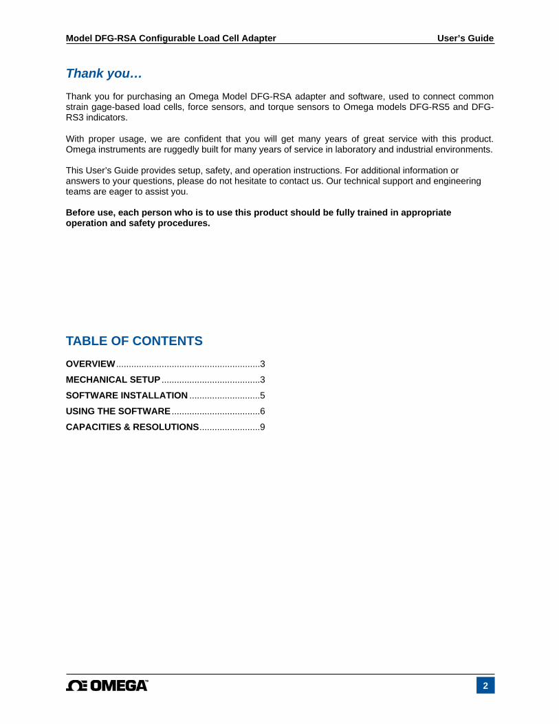
1. Access the circuit board inside the DFG-RSA adapter by loosening two Phillips head screws and removing the cover, as shown in the image below:
Model DFG-RSA Configurable Load Cell Adapter User’s Guide
4
The screw terminal block will be visible, along with labels referencing the functions listed above:
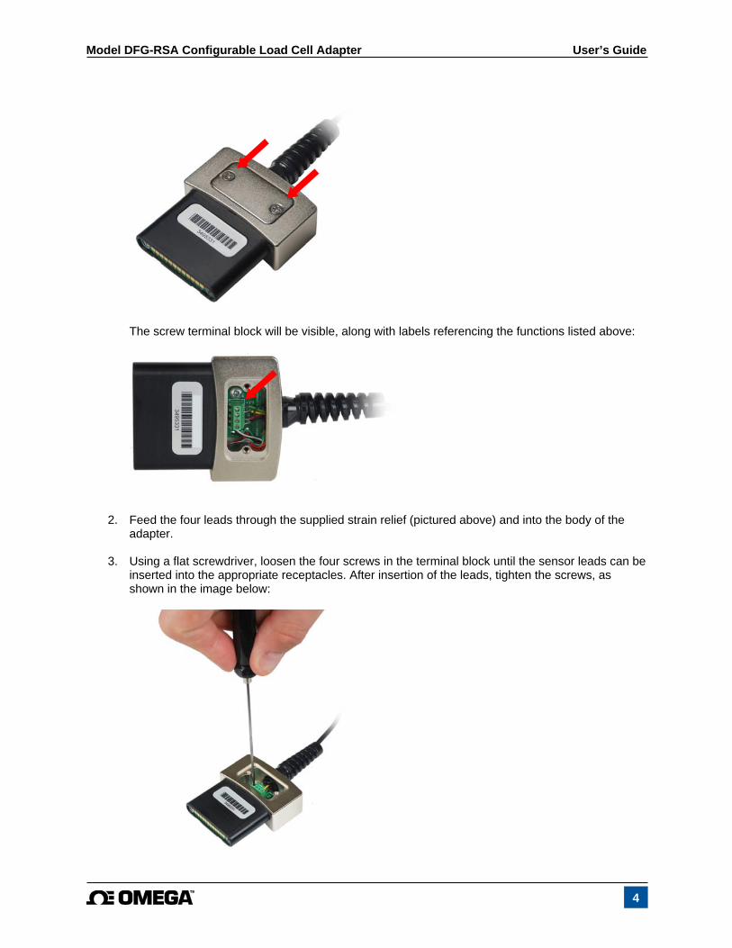
2. Feed the four leads through the supplied strain relief (pictured above) and into the body of the adapter.
3. Using a flat screwdriver, loosen the four screws in the terminal block until the sensor leads can be inserted into the appropriate receptacles. After insertion of the leads, tighten the screws, as shown in the image below:
Model DFG-RSA Configurable Load Cell Adapter User’s Guide
5
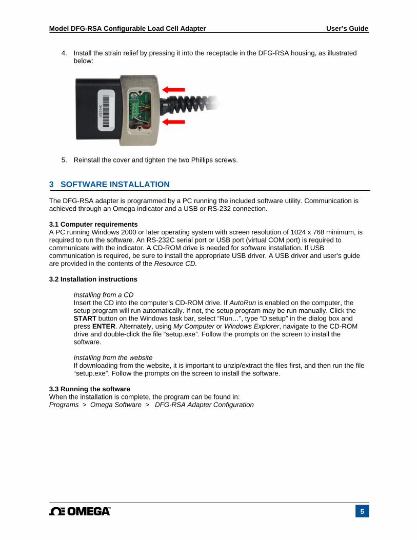
4. Install the strain relief by pressing it into the receptacle in the DFG-RSA housing, as illustrated below:
5. Reinstall the cover and tighten the two Phillips screws.
3 SOFTWARE INSTALLATION The DFG-RSA adapter is programmed by a PC running the included software utility. Communication is achieved through an Omega indicator and a USB or RS-232 connection. 3.1 Computer requirements A PC running Windows 2000 or later operating system with screen resolution of 1024 x 768 minimum, is required to run the software. An RS-232C serial port or USB port (virtual COM port) is required to communicate with the indicator. A CD-ROM drive is needed for software installation. If USB communication is required, be sure to install the appropriate USB driver. A USB driver and user’s guide are provided in the contents of the Resource CD. 3.2 Installation instructions
Installing from a CD Insert the CD into the computer’s CD-ROM drive. If AutoRun is enabled on the computer, the setup program will run automatically. If not, the setup program may be run manually. Click the START button on the Windows task bar, select “Run…”, type “D:setup” in the dialog box and press ENTER. Alternately, using My Computer or Windows Explorer, navigate to the CD-ROM drive and double-click the file “setup.exe”. Follow the prompts on the screen to install the software.
Installing from the website If downloading from the website, it is important to unzip/extract the files first, and then run the file “setup.exe”. Follow the prompts on the screen to install the software.
3.3 Running the software When the installation is complete, the program can be found in: Programs > Omega Software > DFG-RSA Adapter Configuration
Model DFG-RSA Configurable Load Cell Adapter User’s Guide
6
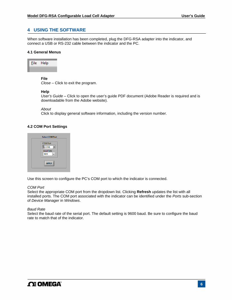
4 USING THE SOFTWARE When software installation has been completed, plug the DFG-RSA adapter into the indicator, and connect a USB or RS-232 cable between the indicator and the PC. 4.1 General Menus
File Close – Click to exit the program.
Help User’s Guide – Click to open the user’s guide PDF document (Adobe Reader is required and is downloadable from the Adobe website). About Click to display general software information, including the version number.
4.2 COM Port Settings
Use this screen to configure the PC’s COM port to which the indicator is connected. COM Port Select the appropriate COM port from the dropdown list. Clicking Refresh updates the list with all installed ports. The COM port associated with the indicator can be identified under the Ports sub-section of Device Manager in Windows. Baud Rate Select the baud rate of the serial port. The default setting is 9600 baud. Be sure to configure the baud rate to match that of the indicator.
Model DFG-RSA Configurable Load Cell Adapter User’s Guide
7
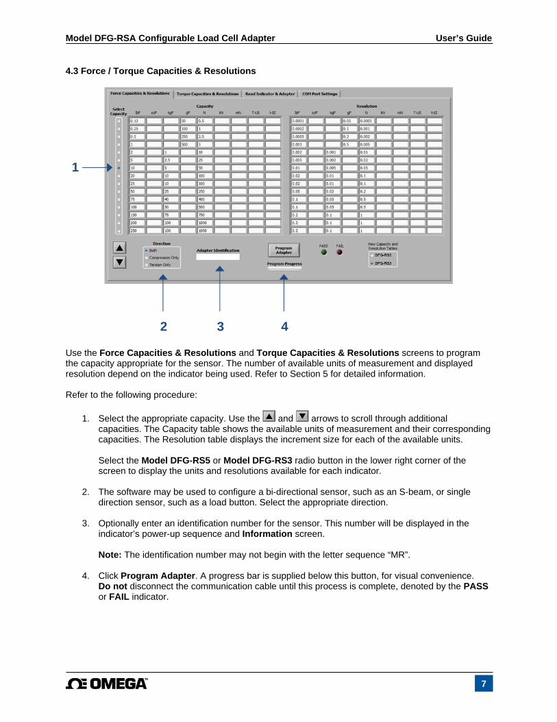
4.3 Force / Torque Capacities & Resolutions
Use the Force Capacities & Resolutions and Torque Capacities & Resolutions screens to program the capacity appropriate for the sensor. The number of available units of measurement and displayed resolution depend on the indicator being used. Refer to Section 5 for detailed information. Refer to the following procedure:
1. Select the appropriate capacity. Use the and arrows to scroll through additional capacities. The Capacity table shows the available units of measurement and their corresponding capacities. The Resolution table displays the increment size for each of the available units. Select the Model DFG-RS5 or Model DFG-RS3 radio button in the lower right corner of the screen to display the units and resolutions available for each indicator.
2. The software may be used to configure a bi-directional sensor, such as an S-beam, or single direction sensor, such as a load button. Select the appropriate direction.
3. Optionally enter an identification number for the sensor. This number will be displayed in the
indicator’s power-up sequence and Information screen. Note: The identification number may not begin with the letter sequence “MR”.
4. Click Program Adapter. A progress bar is supplied below this button, for visual convenience.
Do not disconnect the communication cable until this process is complete, denoted by the PASS or FAIL indicator.
3
1
4 2

Model DFG-RSA Configurable Load Cell Adapter User’s Guide
8
4.4 Read Indicator & Adapter
Use this screen to view information about the sensor and indicator. Click Read to view the indicator model number, serial number, and firmware version. The sensor’s identification number, serial number, direction(s), capacities, and resolutions are also visible. Note: The adapter’s serial number is programmed at the factory and cannot be modified.

Model DFG-RSA Configurable Load Cell Adapter User’s Guide
9
5 CAPACITIES & RESOLUTIONS 5.1 Force Capacities & Resolutions – with Model DFG-RS5
Capacity Resolution
lbF
ozF
kgF
gF
N
kN
mN
T-U
S*
t-S
I*
lbF
ozF
kgF
gF
N
kN
mN
T-U
S*
t-S
I*
0.12 2 - 50 0.5 - 500 - - 0.00005 0.001 - 0.02 0.0002 - 0.2 - - 0.25 4 - 100 1 - 1000 - - 0.0001 0.002 - 0.05 0.0005 - 0.5 - - 0.5 8 - 250 2.5 - 2500 - - 0.0002 0.005 - 0.1 0.001 - 1 - - 1 16 - 500 5 - 5000 - - 0.0005 0.01 - 0.2 0.002 - 2 - - 2 32 1 1000 10 - - - - 0.001 0.02 0.0005 0.5 0.005 - - - - 5 80 2.5 2500 25 - - - - 0.002 0.05 0.001 1 0.01 - - - - 10 160 5 5000 50 - - - - 0.005 0.1 0.002 2 0.02 - - - - 20 320 10 10000 100 - - - - 0.01 0.2 0.005 5 0.05 - - - - 25 400 10 10000 100 - - - - 0.01 0.2 0.005 5 0.05 - - - - 50 800 25 25000 250 - - - - 0.02 0.5 0.01 10 0.1 - - - - 75 1200 40 40000 400 - - - - 0.05 0.5 0.02 20 0.2 - - - - 100 1600 50 50000 500 - - - - 0.05 1 0.02 20 0.2 - - - - 150 2400 75 75000 750 - - - - 0.1 2 0.05 50 0.5 - - - - 200 3200 100 100000 1000 - - - - 0.1 2 0.05 50 0.5 - - - - 250 4000 100 - 1000 1 - - - 0.1 2 0.05 - 0.5 0.0005 - - - 300 4800 150 - 1500 1.5 - - - 0.2 5 0.1 - 1 0.001 - - - 500 8000 250 - 2500 2.5 - - - 0.2 5 0.1 - 1 0.001 - - - 750 12000 400 - 4000 4 - - - 0.5 10 0.2 - 2 0.002 - - -
1000 16000 500 - 5000 5 - - - 0.5 10 0.2 - 2 0.002 - - - 1500 24000 750 - 7500 7.5 - - - 1 20 0.5 - 5 0.005 - - - 2000 - 1000 - - 10 - 1 1 1 - 0.5 - - 0.005 - 0.0005 0.0005 2500 - 1000 - - 10 - 1 1 1 - 0.5 - - 0.005 - 0.0005 0.0005 3000 - 1500 - - 15 - 1.5 1.5 2 - 1 - - 0.01 - 0.001 0.001 5000 - 2500 - - 25 - 2.5 2.5 2 - 1 - - 0.01 - 0.001 0.001 7500 - 4000 - - 40 - 4 4 5 - 2 - - 0.02 - 0.002 0.002 10000 - 5000 - - 50 - 5 5 5 - 2 - - 0.02 - 0.002 0.002 15000 - 7500 - - 75 - 7.5 7.5 10 - 5 - - 0.05 - 0.005 0.005 20000 - 10000 - - 100 - 10 10 10 - 5 - - 0.05 - 0.005 0.005 25000 - 10000 - - 100 - 10 10 10 - 5 - - 0.05 - 0.005 0.005 30000 - 15000 - - 150 - 15 15 20 - 10 - - 0.1 - 0.01 0.01 50000 - 25000 - - 250 - 25 25 20 - 10 - - 0.1 - 0.01 0.01 75000 - 40000 - - 400 - 40 40 50 - 20 - - 0.2 - 0.02 0.02 100000 - 50000 - - 500 - 50 50 50 - 20 - - 0.2 - 0.02 0.02 150000 - 75000 - - 750 - 75 75 100 - 50 - - 0.5 - 0.05 0.05 200000 - 100000 - - 1000 - 100 100 100 - 50 - - 0.5 - 0.05 0.05 250000 - 100000 - - 1000 - 100 100 100 - 50 - - 0.5 - 0.05 0.05 300000 - 150000 - - 1500 - 150 150 200 - 100 - - 1 - 0.1 0.1 500000 - 250000 - - 2500 - 250 250 200 - 100 - - 1 - 0.1 0.1 750000 - 400000 - - 4000 - 400 400 500 - 200 - - 2 - 0.2 0.2
* T-US = US ton t-SI = metric ton
Model DFG-RSA Configurable Load Cell Adapter User’s Guide
10
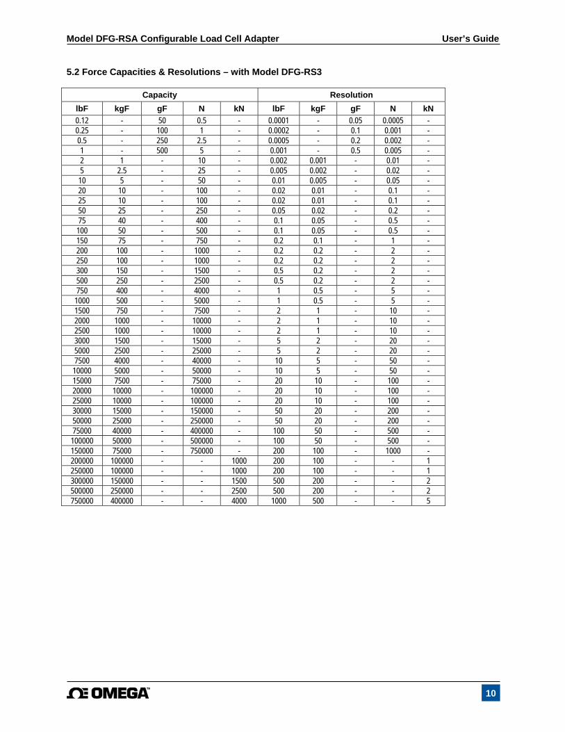
5.2 Force Capacities & Resolutions – with Model DFG-RS3
Capacity Resolution
lbF kgF gF N kN lbF kgF gF N kN
0.12 - 50 0.5 - 0.0001 - 0.05 0.0005 - 0.25 - 100 1 - 0.0002 - 0.1 0.001 - 0.5 - 250 2.5 - 0.0005 - 0.2 0.002 - 1 - 500 5 - 0.001 - 0.5 0.005 - 2 1 - 10 - 0.002 0.001 - 0.01 - 5 2.5 - 25 - 0.005 0.002 - 0.02 - 10 5 - 50 - 0.01 0.005 - 0.05 - 20 10 - 100 - 0.02 0.01 - 0.1 - 25 10 - 100 - 0.02 0.01 - 0.1 - 50 25 - 250 - 0.05 0.02 - 0.2 - 75 40 - 400 - 0.1 0.05 - 0.5 - 100 50 - 500 - 0.1 0.05 - 0.5 - 150 75 - 750 - 0.2 0.1 - 1 - 200 100 - 1000 - 0.2 0.2 - 2 - 250 100 - 1000 - 0.2 0.2 - 2 - 300 150 - 1500 - 0.5 0.2 - 2 - 500 250 - 2500 - 0.5 0.2 - 2 - 750 400 - 4000 - 1 0.5 - 5 -
1000 500 - 5000 - 1 0.5 - 5 - 1500 750 - 7500 - 2 1 - 10 - 2000 1000 - 10000 - 2 1 - 10 - 2500 1000 - 10000 - 2 1 - 10 - 3000 1500 - 15000 - 5 2 - 20 - 5000 2500 - 25000 - 5 2 - 20 - 7500 4000 - 40000 - 10 5 - 50 - 10000 5000 - 50000 - 10 5 - 50 - 15000 7500 - 75000 - 20 10 - 100 - 20000 10000 - 100000 - 20 10 - 100 - 25000 10000 - 100000 - 20 10 - 100 - 30000 15000 - 150000 - 50 20 - 200 - 50000 25000 - 250000 - 50 20 - 200 - 75000 40000 - 400000 - 100 50 - 500 - 100000 50000 - 500000 - 100 50 - 500 - 150000 75000 - 750000 - 200 100 - 1000 - 200000 100000 - - 1000 200 100 - - 1 250000 100000 - - 1000 200 100 - - 1 300000 150000 - - 1500 500 200 - - 2 500000 250000 - - 2500 500 200 - - 2 750000 400000 - - 4000 1000 500 - - 5
Model DFG-RSA Configurable Load Cell Adapter User’s Guide
11
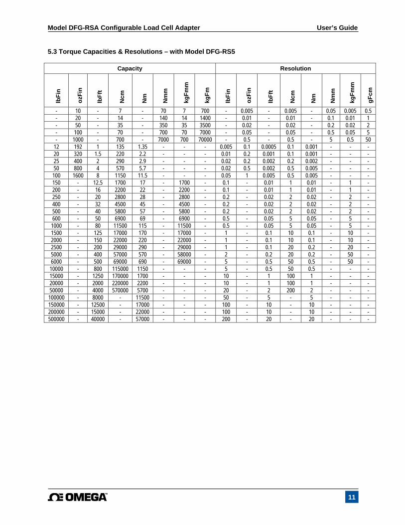
5.3 Torque Capacities & Resolutions – with Model DFG-RS5
Capacity Resolution
lbF
in
ozF
in
lbF
ft
Ncm
Nm
Nm
m
kgF
mm
kgF
m
lbF
in
ozF
in
lbF
ft
Ncm
Nm
Nm
m
kgF
mm
gF
cm
- 10 - 7 - 70 7 700 - 0.005 - 0.005 - 0.05 0.005 0.5 - 20 - 14 - 140 14 1400 - 0.01 - 0.01 - 0.1 0.01 1 - 50 - 35 - 350 35 3500 - 0.02 - 0.02 - 0.2 0.02 2 - 100 - 70 - 700 70 7000 - 0.05 - 0.05 - 0.5 0.05 5 - 1000 - 700 - 7000 700 70000 - 0.5 - 0.5 - 5 0.5 50
12 192 1 135 1.35 - - - 0.005 0.1 0.0005 0.1 0.001 - - - 20 320 1.5 220 2.2 - - - 0.01 0.2 0.001 0.1 0.001 - - - 25 400 2 290 2.9 - - - 0.02 0.2 0.002 0.2 0.002 - - - 50 800 4 570 5.7 - - - 0.02 0.5 0.002 0.5 0.005 - - - 100 1600 8 1150 11.5 - - - 0.05 1 0.005 0.5 0.005 - - - 150 - 12.5 1700 17 - 1700 - 0.1 - 0.01 1 0.01 - 1 - 200 - 16 2200 22 - 2200 - 0.1 - 0.01 1 0.01 - 1 - 250 - 20 2800 28 - 2800 - 0.2 - 0.02 2 0.02 - 2 - 400 - 32 4500 45 - 4500 - 0.2 - 0.02 2 0.02 - 2 - 500 - 40 5800 57 - 5800 - 0.2 - 0.02 2 0.02 - 2 - 600 - 50 6900 69 - 6900 - 0.5 - 0.05 5 0.05 - 5 -
1000 - 80 11500 115 - 11500 - 0.5 - 0.05 5 0.05 - 5 - 1500 - 125 17000 170 - 17000 - 1 - 0.1 10 0.1 - 10 - 2000 - 150 22000 220 - 22000 - 1 - 0.1 10 0.1 - 10 - 2500 - 200 29000 290 - 29000 - 1 - 0.1 20 0.2 - 20 - 5000 - 400 57000 570 - 58000 - 2 - 0.2 20 0.2 - 50 - 6000 - 500 69000 690 - 69000 - 5 - 0.5 50 0.5 - 50 - 10000 - 800 115000 1150 - - - 5 - 0.5 50 0.5 - - - 15000 - 1250 170000 1700 - - - 10 - 1 100 1 - - - 20000 - 2000 220000 2200 - - - 10 - 1 100 1 - - - 50000 - 4000 570000 5700 - - - 20 - 2 200 2 - - - 100000 - 8000 - 11500 - - - 50 - 5 - 5 - - - 150000 - 12500 - 17000 - - - 100 - 10 - 10 - - - 200000 - 15000 - 22000 - - - 100 - 10 - 10 - - - 500000 - 40000 - 57000 - - - 200 - 20 - 20 - - -
Model DFG-RSA Configurable Load Cell Adapter User’s Guide
12
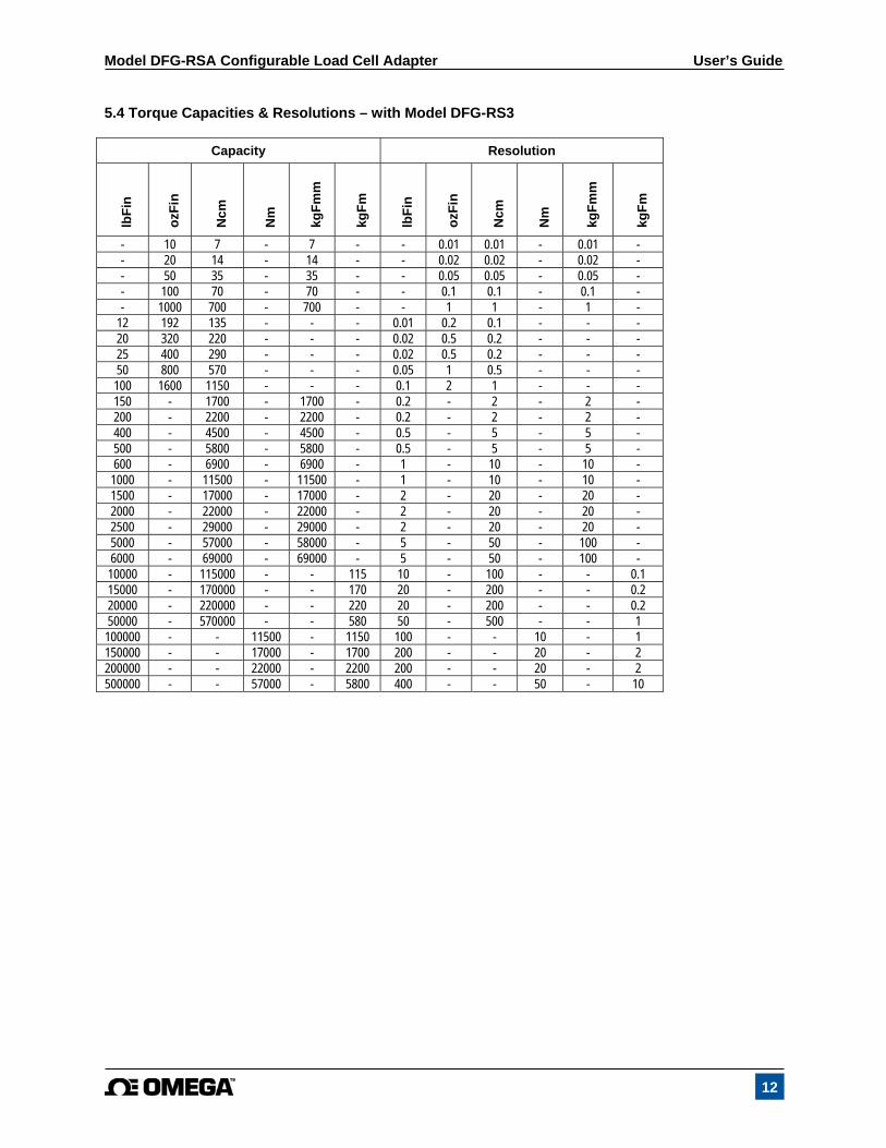
5.4 Torque Capacities & Resolutions – with Model DFG-RS3
Capacity Resolution
lbF
in
ozF
in
Ncm
Nm
kgF
mm
kgF
m
lbF
in
ozF
in
Ncm
Nm
kgF
mm
kgF
m
- 10 7 - 7 - - 0.01 0.01 - 0.01 - - 20 14 - 14 - - 0.02 0.02 - 0.02 - - 50 35 - 35 - - 0.05 0.05 - 0.05 - - 100 70 - 70 - - 0.1 0.1 - 0.1 - - 1000 700 - 700 - - 1 1 - 1 -
12 192 135 - - - 0.01 0.2 0.1 - - - 20 320 220 - - - 0.02 0.5 0.2 - - - 25 400 290 - - - 0.02 0.5 0.2 - - - 50 800 570 - - - 0.05 1 0.5 - - - 100 1600 1150 - - - 0.1 2 1 - - - 150 - 1700 - 1700 - 0.2 - 2 - 2 - 200 - 2200 - 2200 - 0.2 - 2 - 2 - 400 - 4500 - 4500 - 0.5 - 5 - 5 - 500 - 5800 - 5800 - 0.5 - 5 - 5 - 600 - 6900 - 6900 - 1 - 10 - 10 -
1000 - 11500 - 11500 - 1 - 10 - 10 - 1500 - 17000 - 17000 - 2 - 20 - 20 - 2000 - 22000 - 22000 - 2 - 20 - 20 - 2500 - 29000 - 29000 - 2 - 20 - 20 - 5000 - 57000 - 58000 - 5 - 50 - 100 - 6000 - 69000 - 69000 - 5 - 50 - 100 - 10000 - 115000 - - 115 10 - 100 - - 0.1 15000 - 170000 - - 170 20 - 200 - - 0.2 20000 - 220000 - - 220 20 - 200 - - 0.2 50000 - 570000 - - 580 50 - 500 - - 1 100000 - - 11500 - 1150 100 - - 10 - 1 150000 - - 17000 - 1700 200 - - 20 - 2 200000 - - 22000 - 2200 200 - - 20 - 2 500000 - - 57000 - 5800 400 - - 50 - 10
Model DFG-RSA Configurable Load Cell Adapter User’s Guide
13
NOTES:
Model DFG-RSA Configurable Load Cell Adapter User’s Guide
14
Model DFG-RSA Configurable Load Cell Adapter User’s Guide
15
M5252/0518