Embed Size (px)
Citation preview
© Raymond Walley 2012 – All rights reserved
LNER Sandringam Class B17 4-6-0 Phoenix Precision Paints, Orwell Court,Wickford, SS11 8YJ Tel: 01268 730549
E-mail: [email protected] Web: https://www.phoenix-paints.co.uk/
Introduction.
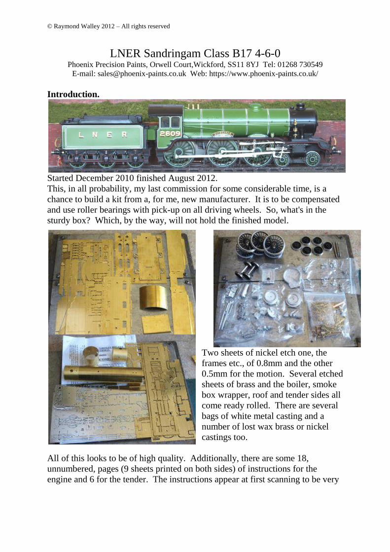
Started December 2010 finished August 2012.
This, in all probability, my last commission for some considerable time, is a
chance to build a kit from a, for me, new manufacturer. It is to be compensated
and use roller bearings with pick-up on all driving wheels. So, what's in the
sturdy box? Which, by the way, will not hold the finished model.
Two sheets of nickel etch one, the
frames etc., of 0.8mm and the other
0.5mm for the motion. Several etched
sheets of brass and the boiler, smoke
box wrapper, roof and tender sides all
come ready rolled. There are several
bags of white metal casting and a
number of lost wax brass or nickel
castings too.
All of this looks to be of high quality. Additionally, there are some 18,
unnumbered, pages (9 sheets printed on both sides) of instructions for the
engine and 6 for the tender. The instructions appear at first scanning to be very

© Raymond Walley 2012 – All rights reserved
comprehensive but, there is an almost complete lack of paragraphing, resulting
in pages of dense text, which makes it difficult, and tedious, to follow.
Though there are useful illustrations there are no exploded diagrams at all save
for one for the motion, but that has errors in it of which, more later. There are
three pages illustrating where various parts fit, line drawings - not to scale - of
either side of the engine, the front and cab end.
However, for the engine all the parts can easily be identified by representations
of the frets and a numbering system referring back to lists. But, the numbering
is not sequential, resulting in, for instance, 2 parts No: 50, depending upon
which etched sheet one is using. That makes it a little confusing.
However, it is clear that the designer has researched his subject and he provides
some useful prototype references.
The first thing I did was unpack the wheels, (obtained from DMR) clean them
up and do my usual modifications of altering the crank pin bolts for 10BA steel,
then I settled down to read all through the instructions, carefully making notes
as I went because, I almost never follow exactly what the designer intended.
Pity about the lack of diagrams, they could probably have saved half a dozen
pages of text and some hours of time. One man's deathless prose is another
man's road to confusion and irritation.
The Frames & Chassis.
It pays to number
the parts and
read through the
instructions to
see where each
goes. They fit
well, mostly, and
one must file off the
cusps to obtain
good mating
surfaces. So,
having worked out what goes where the next job was to fit the various fixing
nuts and bolts and open the rear axle bearing holes to force fit the roller
bearings, which I later changed for a pair with flanges, much easier to ensure
they are at 90° to the frames and the flange also acts as a useful spacer to help
prevent side play.
© Raymond Walley 2012 – All rights reserved
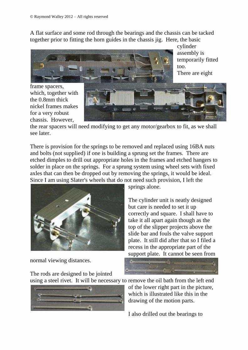
A flat surface and some rod through the bearings and the chassis can be tacked
together prior to fitting the horn guides in the chassis jig. Here, the basic
cylinder
assembly is
temporarily fitted
too.
There are eight
frame spacers,
which, together with
the 0.8mm thick
nickel frames makes
for a very robust
chassis. However,
the rear spacers will need modifying to get any motor/gearbox to fit, as we shall
see later.
There is provision for the springs to be removed and replaced using 16BA nuts
and bolts (not supplied) if one is building a sprung set the frames. There are
etched dimples to drill out appropriate holes in the frames and etched hangers to
solder in place on the springs. For a sprung system using wheel sets with fixed
axles that can then be dropped out by removing the springs, it would be ideal.
Since I am using Slater's wheels that do not need such provision, I left the
springs alone.
The cylinder unit is neatly designed
but care is needed to set it up
correctly and square. I shall have to
take it all apart again though as the
top of the slipper projects above the
slide bar and fouls the valve support
plate. It still did after that so I filed a
recess in the appropriate part of the
support plate. It cannot be seen from
normal viewing distances.
The rods are designed to be jointed
using a steel rivet. It will be necessary to remove the oil bath from the left end
of the lower right part in the picture,
which is illustrated like this in the
drawing of the motion parts.
I also drilled out the bearings to

© Raymond Walley 2012 – All rights reserved
2.4mm - for the Slater's bushes tapped 10BA for the crank pins - and made the
mistake of drilling out this one too, which of course, needs to take a rivet and
not a crank pin. Since Eileen's were out of stock of 'putting on' tools, I sliced a
piece off some 2.4mm rod, soldered it in place, filed it flat on both sides and
drilled it 1mm; here is the completed set of rods.
The connecting rods come as a three piece etch, the rear one is half etched
leaving the bosses at full thickness. They are arranged on the fret and shewn in
the illustration to suggest the half etched side goes inside. Clearly wrong so the
rear elements were swapped over.
The motion for one side laid out prior
to fitting many of the parts together.
The instructions suggest 14BA brass
nuts and bolts and a number are supplied in the kit. Brass nuts would look
terrible so most of it is fitted with soldered nickel pivots with some fixings in
14BA steel. However, the rear crank pins nuts will be modified cast nickel
from CPL, not right for the engine but better by far than the 12BA nuts
suggested.
The ABC motor/gearbox duly arrived and so work started on fitting it to the
frames. There is no mention whatever in the instructions about motors - which
rather surprised me - and no guidance on where one might be fitted. However,
the designer intended for the motor/gearbox to fit on the centre axle.
If one fits all the various spacers in the frames, there is nowhere a motor can be
easily fitted other than the centre axle. I wanted the drive on the rear wheels so,
after some careful measurement I removed the large base-rear spacer, part 12,
and modified it to take the gearbox.
It was necessary also to modify the
rear spacer to allow for the gear
wheels. When it goes back in, part
13, needs to be dispensed with or the
motor will not fit. I could just as
easily have simply cut off a chunk of
part 12 without endangering the
integrity of the frames but this was
more satisfyingly elegant.
The crankpin nuts I use come from CPL and were originally designed by
Malcolm Mitchell. There are two types available, one set for use with AGH
wheels and the other with Slater's wheels.

© Raymond Walley 2012 – All rights reserved
They come ready with cast in 12BA threads, which of course is of no use to me
now as I have altered the crankpin bolts to 10BA. So they need to be drilled out
1.4mm and tapped 10BA, not easy
with such a
tiny nickel
casting.
The large
round brass
tool you can
see is a
crankpin nut
spinner.
Each end
has a hole
drilled in it large enough to take one
of the two sizes of nut and then a slot
is cut across it for the cast gudgeon pin to fit into. This does well for fitting and
tightening the nuts in practice but is also invaluable when it come to altering the
thread.
By clamping the nut spinner in a vice it is possible, with care, both to drill out
the hole using a Dremel drill and re-thread the nuts with a tap held in a pin vice.
Here then, is the
chassis running
(very, very,
slowly), which it
did with very
little fettling.
The only
problem was an
odd knocking that turned out to be the back of the rivet holding the rods
together catching on the wheel bosses.
Some gentle filing down and the
addition of a thin 10BA washer
behind the crankpin bush cured it.
The compensating beam was made
from some strip brass and set high,
using a hole perhaps intended for
plunger pick-ups, so that it is invisible from the side view through the holes in
the frames.

© Raymond Walley 2012 – All rights reserved
The ends bear on some brass tube slid onto the axles to reduce friction. There is
a spacer to go at the top of the frames on the left; it will be left unsoldered and
simply clipped into its locating slots so that the axle tube can be refitted during
future maintenance.
The Bogie.
The bogie is relatively simple but requires careful work to edge solder the
mudguards so they are lined up. Once put together I added a few ounces of lead
strip either side of the pivot slot. The slot was opened out to fit a bearing from
the spares box that fit the securing bolt well. Even so, the bolt is too short and
will have to be replaced but it is possible that I lost the correct one.
The chassis is gradually getting to a stage where the motion can all be set up
and tested before I strip it all apart, clean and chemically blacken it.
The brake gear
goes together
relatively easily.
I added some
brass rod with a
couple of pieces
of tube soldered
in place to
represent the pull
rod and its
tensioner
because they are
visible through the wheels. The support brackets for the motion are cleverly
designed and line up easily using the rod through the frames. I had to cut a
small chunk out of the pivot beam because it fouled the rod.
The Body.
The footplate is a very tricky item and I have not been looking forward to it at
all. There are two etched parts for the valances and one for the footplate. One

© Raymond Walley 2012 – All rights reserved
is forced to use the flimsy valances as a jig along with several parts that edge
solder to the cab
end. It takes a
good deal of time
and much care
but is doable.
Here is the partially
completed job in need
of a good clean-up. It
looks a little hump-
backed at present and
it is quite fragile but,
once more parts have been fitted it should firm up.
When I tried it against the frames the rear fixing holes for each part do not come
close to lining up while the projections on the motion bracket (which can be
seen in the pictures above) need removing or the footplate will not seat.
In addition the rear frame spacer has no rectangular hole in it to match that in
the drag beam so if looks like there are more modifications to be made, we shall
see.
Having now
added the
dummy front
frames, buffer
plank, buffer
housings and
drag beam it is
time to check that the basic parts fit with the cab and frames. That may be the
most difficult part over, now to continue with the upper works before returning
to the motion.
The boiler did
not prove too
difficult, despite
it came rolled
slightly on the
skew but the
handrails may
prove troublesome.

© Raymond Walley 2012 – All rights reserved
There is no central knob on the smoke box door and, since the rails go all the
way round, there is nowhere to hide any joint so it is necessary to produce the
handrails as one item. The manufacturer provides a length long enough for the
job but I suspect that many, like me, will not realize this and merrily cut it up
for other jobs.
The footplate is
now much nearer
to completion.
Exactly how the
front cylinder
covers are fitted
will need to be
worked out since there are no parts identified for that area in the instructions,
which get worse the more I read them. Twice so far, large chunks of text have
been repeated, one of them twice.
Another mock-up
to see how it is
coming along. In
attempting to fit
the boiler to the
footplate I
discovered that I
had not
assembled the cab to the footplate at a right angle and so it had all to be
removed, cleaned
up and re-fitted.
The smoke box
saddle also
needed to be
modified by
opening out the
hole for the chassis fixing bolt and moving the whole thing back a couple of
millimetres.
Once happy with it I Araldited it in place and then followed this by permanently
fitting the boiler/smoke box. It is Araldited to the smoke box saddle and
soldered to the footplate.
To ensure that there is a strong joint at the rear I added some 1x2mm brass
square section, suitable bent to shape, inside the boiler abutting the cab and

© Raymond Walley 2012 – All rights reserved
soldered it all solid. An edge solder here, in my opinion, would be very
unsatisfactory and easily liable to fracture over time.
A good deal of fettling was required to achieve a close fit of the boiler in the
footplate, though even now there are gaps that will have to be filled later. Here
then is the build so far:
The dome casting
had its feed on
the base where it
fits the boiler
making for a
difficult clean up,
why not on the
centre spindle?
The chimney is
useless, poorly
cast - which no
doubt could
easily be changed
- but the curve of the base does not match that of the boiler so we decided on a
Laurie Griffin replacement.
The other side of the boiler: the Westinghouse gear comes as a very nice lost
wax casting, two of the pipes need cutting off at the joint, drilling 0.8mm and
wire soldered in. One to go the full length of the boiler and here I drilled a hole
in the cab to give me another point to anchor the whole unit. The other winds
around the back of the unit and disappears between the frames.
The vacuum pipe provided is far too short to fit across the depth of buffer beam
and then vanish under it and I had to cut it short at the bracket fixing to the
beam, drill it out and fit a suitable length of wire; poor choice of castings.
Having
blackened the
chassis and bogie
the time has
come to mock it
up and get some
idea of how the
build is
progressing.
© Raymond Walley 2012 – All rights reserved
The steps on the footplate beside the cab were a bit of a trial. One side fits
reasonably well, the other side does not because the pairs do not appear to have
been drawn as mirror images, result, much fettling to force them to fit. There
are still some parts to be fitted to the body.
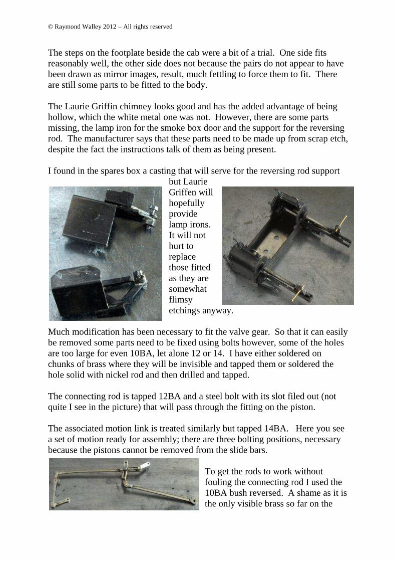
The Laurie Griffin chimney looks good and has the added advantage of being
hollow, which the white metal one was not. However, there are some parts
missing, the lamp iron for the smoke box door and the support for the reversing
rod. The manufacturer says that these parts need to be made up from scrap etch,
despite the fact the instructions talk of them as being present.
I found in the spares box a casting that will serve for the reversing rod support
but Laurie
Griffen will
hopefully
provide
lamp irons.
It will not
hurt to
replace
those fitted
as they are
somewhat
flimsy
etchings anyway.
Much modification has been necessary to fit the valve gear. So that it can easily
be removed some parts need to be fixed using bolts however, some of the holes
are too large for even 10BA, let alone 12 or 14. I have either soldered on
chunks of brass where they will be invisible and tapped them or soldered the
hole solid with nickel rod and then drilled and tapped.
The connecting rod is tapped 12BA and a steel bolt with its slot filed out (not
quite I see in the picture) that will pass through the fitting on the piston.
The associated motion link is treated similarly but tapped 14BA. Here you see
a set of motion ready for assembly; there are three bolting positions, necessary
because the pistons cannot be removed from the slide bars.
To get the rods to work without
fouling the connecting rod I used the
10BA bush reversed. A shame as it is
the only visible brass so far on the

© Raymond Walley 2012 – All rights reserved
motion.
In order for the connecting rod to
clear, it was also necessary originally
to fit 2mm of bushing between the connecting rod big end and the side rod. I
was not happy about that at all and altered the connecting rods slightly to get rid
of it.
Finally the side
and connecting
rods and pistons
are all set-up,
proved and then
tested on the
rolling road. The
piston rods needed shortening to prevent them trying to knock the cylinder
covers off; I had forgotten to check this earlier.
The valve gear promises to be a great deal more difficult. The pick-ups needed
fitting and the
client did not
want the
'American'
method I favour.
The kit comes
with some pieces
of copper clad to
manufacture
pick-ups to rub on the rims or backs of the wheels.
There was no way that these would work fitted with the pick-up running on top
of the wheels, my preferred method for scratchers and fitting underneath would
have produced a lot of extra stuff to spoil the view between the spokes, and
been prone to damage.
I decided to fit plungers instead so, off with the wheels and drill the side frames
out for the plunger fittings, (there are holes already in the frames for these but I
had used some of them for other things) the front and centre drivers at the top
and the rear behind the brake block. I also took the opportunity to fit the
balance weights and blacken the wheels.
The wires could now be nicely hidden away under the footplate. Setting them
up was easy but required washers to extend them out due to the frames being
somewhat narrow. A check on the rolling road confirmed that there was no
excessive drag causing higher than normal current draw.

© Raymond Walley 2012 – All rights reserved
The back-head, reversing lever and handrails and sundry other pipes are about
all that's left to do I think. Though, in my experience, the final picture often
reveals something that has been missed!
Modifications to the cab floor were
needed I think or it would never have
got round tight curves. I cut down the
footplate in the cab, fitted the fall
plate and then extended the footplate
for the tender so that the fall plate
would reach it by using the piece I
had removed from the cab thus:
That also gave me the chance to
reduce the size and placing of the cut-
outs for the brake and water scoop
standards. Those on the original piece
were too large and did not line up
properly.
The handrail is 'interesting' as noted
earlier; it needs a single length of wire
effectively to get it right; I had ‘used’ the one provided but fortunately I had
some long lengths of nickel silver in stock.
It is now virtually complete requiring only the valve gear's final fitting, which
will be done after it gets back from the painter, along with the back-head. The
latter will have to wait a while as Laurie Griffin cannot supply for a couple of
months. However, since I never fix them permanently anyway, this is not a
problem.
The cab doors had to be made from scratch. Those provided were to scale and
so would never have covered the out of scale gap between engine and tender
necessary for it to go round sub 6' radius curves.
The Tender.
My original instructions for the tender were incomplete but an e-mail to DMR
brought a new set very quickly. There are nine pages and, like the engine
instructions, the text is rather dense. There are lists of parts but no picture of
any of the etched sheets to match them against, which in some cases make it
difficult to identify which part goes where.
© Raymond Walley 2012 – All rights reserved
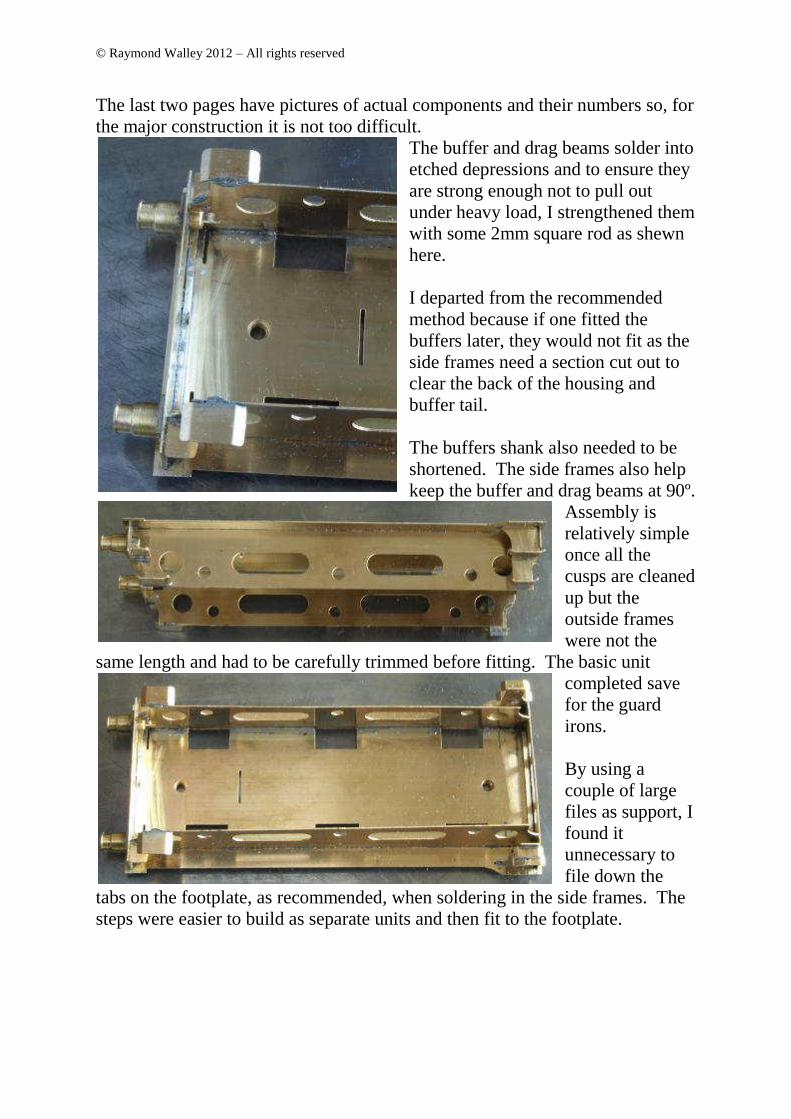
The last two pages have pictures of actual components and their numbers so, for
the major construction it is not too difficult.
The buffer and drag beams solder into
etched depressions and to ensure they
are strong enough not to pull out
under heavy load, I strengthened them
with some 2mm square rod as shewn
here.
I departed from the recommended
method because if one fitted the
buffers later, they would not fit as the
side frames need a section cut out to
clear the back of the housing and
buffer tail.
The buffers shank also needed to be
shortened. The side frames also help
keep the buffer and drag beams at 90º.
Assembly is
relatively simple
once all the
cusps are cleaned
up but the
outside frames
were not the
same length and had to be carefully trimmed before fitting. The basic unit
completed save
for the guard
irons.
By using a
couple of large
files as support, I
found it
unnecessary to
file down the
tabs on the footplate, as recommended, when soldering in the side frames. The
steps were easier to build as separate units and then fit to the footplate.

© Raymond Walley 2012 – All rights reserved
The brakes are
simple, though
the shoes are
much too thin
and could have
been improved
with an extra
layer or two to
thicken them.
There is no
provision for
compensation
and no space to
fit it either, not
even room to
open out the centre holes in the centre wheel set to allow some up and down
movement without some significant modification but, it ran well enough.
Brake set-up is
very simple but
the pull rods
when I first put
them on were
very close to the
wheels. I
thought they
would need
careful packing to ensure they stay on course or; to use longer cross shafts
linking the bottom of the hangers. A further look at the Isinglass drawing
however shews
that the pull rods
go inside the
wheels so, take it
all off again
(morale? dry
run!) and correct
it thus:
There is ample room here to fit pick-ups to rub on the back of the wheels if
required.

© Raymond Walley 2012 – All rights reserved
The sides come ready formed for the flare and side plates. Unfortunately, the
pre-formed flare does not match the curve necessary to fit the rear coal plate so
it was necessary to anneal and reform.
Consequently,
the sides became
a little distorted
and would not fit
the base easily as
shewn here:
Under normal
circumstances
this would be a
simple edge
solder and
therefore I think not necessarily
very robust. I got round this
by soldering in some square
brass tube, which required less
heat, along each edge of the
base.
Here you can see how I set up
the temporary jig to ensure it all
went in square. Now the sides
and back are soldered in place
square however, it is clear that
the flare does not meet at the
rear corners and needed filling.
For small gaps Milliput will do
fine but for the large gap I
had to solder in some wire
first, in-fill with solder and
then file to shape. Not
ideal.
The beading is provided as
an etched item to solder in
place, not a particularly
easy job on the tender sides

© Raymond Walley 2012 – All rights reserved
but somewhat easier than using wire, which is suggested as an alternative.
The top of the tender is
partially located by the rear
coal plate, which is slotted
through it and into the base.
However, there is nothing
to support the front making
it difficult to fit and solder
up. I soldered some 2mm
brass bar behind the tender
front just below where the
shovel plate fits such that
the front of the top sits on it
at the right level.
The tender footplate is
inaccurate in that when
offered up after fitting the
brake and water scoop
controls, does not fit to
accommodate their centres.
It needed the half-round
indents to be opened out
sideways and deepened
considerably so that the
part would fit correctly.
The coal plates that locate
on the top of the tender
require some careful fitting
especially that on the left
(viewed from the rear) and
both parts are entirely edge
soldered. In fact there is a
great deal of edge soldering
required in this kit, often
with little or no anchoring
point as a starting position.
There are four lamp irons to be fitted to the tender top but the holes for them are
woefully undersize and the wrong shape. They were a pain to correct and
should have been properly etched at the outset.
© Raymond Walley 2012 – All rights reserved
The last job to do for the tender is fitting all the white metal castings. There are
a good many that obviously come from good masters, unfortunately it seems the
moulds for some were badly worn and there is as a consequence a good deal of
flash to clean off, some of it very difficult because it is not easily accessible or
obliterates some detail.
There is a pair of nice castings for the sand boxes with brass rod pipes already
fitted. Unfortunately they will not fit in the space intended for them. Since they
cannot be seen in normal service I simply soldered some appropriately bent
1mm rod in place for the pipes.
The buffers had to be modified by shortening the shank to the minimum
possible in order that the tail will fit in the slot I cut in the frames.
The tool box needed a piece of brass soldering in behind the tender front to act
as a platform to hold it in place. The instructions refer to this specifically as the
tool boxes were moved around a good deal.
The short pipes on the top exiting the filler covers, if used as supplied, lie at an
angle instead of flat because of the elbow in the pipe. I cut slivers from some
brass tube to put over the other end so that the pipe lay horizontally.
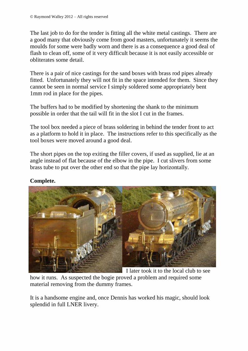
Complete.
I later took it to the local club to see
how it runs. As suspected the bogie proved a problem and required some
material removing from the dummy frames.
It is a handsome engine and, once Dennis has worked his magic, should look
splendid in full LNER livery.
© Raymond Walley 2012 – All rights reserved
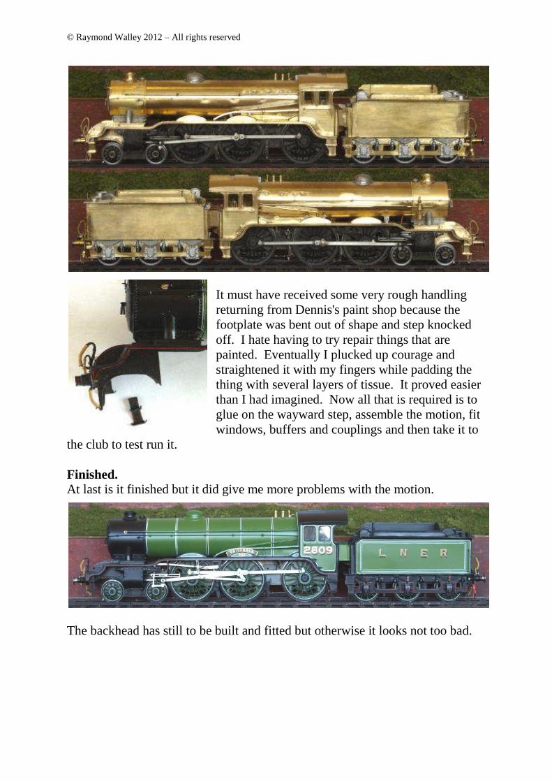
It must have received some very rough handling
returning from Dennis's paint shop because the
footplate was bent out of shape and step knocked
off. I hate having to try repair things that are
painted. Eventually I plucked up courage and
straightened it with my fingers while padding the
thing with several layers of tissue. It proved easier
than I had imagined. Now all that is required is to
glue on the wayward step, assemble the motion, fit
windows, buffers and couplings and then take it to
the club to test run it.
Finished.
At last is it finished but it did give me more problems with the motion.
The backhead has still to be built and fitted but otherwise it looks not too bad.
© Raymond Walley 2012 – All rights reserved
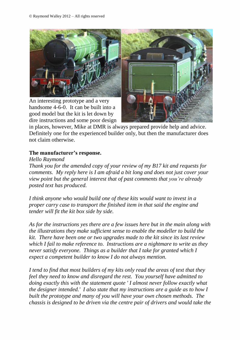
An interesting prototype and a very
handsome 4-6-0. It can be built into a
good model but the kit is let down by
dire instructions and some poor design
in places, however, Mike at DMR is always prepared provide help and advice.
Definitely one for the experienced builder only, but then the manufacturer does
not claim otherwise.
The manufacturer’s response.
Hello Raymond
Thank you for the amended copy of your review of my B17 kit and requests for
comments. My reply here is I am afraid a bit long and does not just cover your
view point but the general interest that of past comments that you’re already
posted text has produced.
I think anyone who would build one of these kits would want to invest in a
proper carry case to transport the finished item in that said the engine and
tender will fit the kit box side by side.
As for the instructions yes there are a few issues here but in the main along with
the illustrations they make sufficient sense to enable the modeller to build the
kit. There have been one or two upgrades made to the kit since its last review
which I fail to make reference to. Instructions are a nightmare to write as they
never satisfy everyone. Things as a builder that I take for granted which I
expect a competent builder to know I do not always mention.
I tend to find that most builders of my kits only read the areas of text that they
feel they need to know and disregard the rest. You yourself have admitted to
doing exactly this with the statement quote ' I almost never follow exactly what
the designer intended.' I also state that my instructions are a guide as to how I
built the prototype and many of you will have your own chosen methods. The
chassis is designed to be driven via the centre pair of drivers and would take the

© Raymond Walley 2012 – All rights reserved
Slater's GB01 motor gearbox units without any modifications. As this is quite a
large unit most other manufactured drive units will also fit. If asked at point of
sale I freely give this information and am able to show them a completed kit
with this in.
This is only a guide as many modellers have their own preference so sorry for
not stating this in the instructions. Your chosen method of drive being the rear
wheels in this case gave you a lot of extra work along with the fitting of beam
suspension. The chassis although designed to take horn blocks was never
designed with beam type suspension in mind in doing so you used the centre
driving wheel plunger pick up points. The chassis has pilot plunger pick up
hole pre-drilled for all drivers.
The brake gear I am at a bit of a loss here you state that you had to use brass
rod and tube to represent the pull rods and tensioners. The illustrations clearly
show that you have used the nickel silver pull rods and assembled the rigging as
per the intended instructions.
I have just noticed that I have failed to mention the top slipper on the piston.
This has already been removed from all recent kits so this problem no longer
exists; you will still need to check on the length and cut accordingly. The bogie
fixing bolt too short NO as I clearly showed you at Telford the bolt I use on the
made up model is exactly the same as supplied in the kit along with the spring
and bearing. I think you used this bolt elsewhere. The folding of the footplate
should pose no problem to the experienced builders. The secret here is to form
the folds a little bit at a time on each side this will ensure that the length of the
running plate will be the same down both sides. The alternative is to make a jig
up as John Cockcroft did when he was commissioned to build his first batch of
four. You also then have a readymade jig for any further builds you may make.
John has used his jig on several more builds with his last being on show at
Telford last week. John has certainly mastered this kit now and I like to think
that he learned from his mistake of trying to be too clever when he made his one
(Review BRM) a process he did not apply to his further three builds or
subsequent builds since.
Raymond sorry for the diversion from your build, However I will elaborate on
my last comment later at the end. The footplate at this stage is quite flimsy as
stated and you did the right thing in offering it up against the chassis to check
the hole alignment. However you found that your chassis and footplate holes
did not line up they should have done. It is easy to get the folds slightly wrong,
this will either increase or decrease the distances between the front and rear
fixing points. This will show up later as more body parts are fitted. As you
state that you had to remove the cab later and reposition when you came to
© Raymond Walley 2012 – All rights reserved
fitting the boiler I suspect that was where the problem lay. The body all makes
up to a very solid mass. As to your handrail wire problem, it is important to
keep back a length for the boiler section as it is best fitted in one section. All
too often we are inclined to pick up the wire and cut off a bit here and here and
before long have not saved a long length for the boiler. There is plenty of wire
supplied in the kit so this should not have been a problem.
I note from your text that you prefer to use araldite to fix the saddle to the boiler
and then solder this to the footplate, as you felt that a solder joint of the boiler
to the saddle would not be strong enough and could crack later. If you are
happy with that method fine however I would like to point out the following
points here. If the parts are suitably fluxed and held together tightly then when
heat is applied to the joint the flux when activated will draw the solder into the
joints. As a plumber by trade this is the exact principle applied when soldering
copper pipe joints. By using resin glues such as araldite if you require to solder
further parts around the area you may encounter a problem with your fluxes not
working properly and subsequent failed solder joint due to oil residues from the
resin. Similarly if superglue is used not only will the joint not be successful but
you risk damage to your health by the cyanide mustard type gas given off.
Raymond I have added this section as a warning and not as a reflection of your
work. All too often I am asked to repair/restore items that have put together
with these mediums and well concealed with paint. As to the white metal
castings I use an experienced outside caster to make my moulds and do the
casting. He casts the dome in the way he does to make sure that you end up
with a round dome and not an oval dome as would probably be the case if it
were cast on its side. The chimney I know may look untidy but I have always
managed to use it. I am aware of Laurie Giffin's chimney and know a few
others that have done the same. It is also very unusual for there to be any
excess flash on the castings. The fact that you were able to use all the castings
with the exception of the chimney I find reassuring.
As to the valve gear yes I supply nuts and bolts but I also supply Nickel Silver
rivets as well I also prefer to use the rivets. As for the valve gear holes being
too big I have never encountered that in fact I find that I have to ease the fixing
holes. Shortening the cab floor and adding the cut off piece to the tender to
ease it better round curves, I found this strange especially as you left the cab
floor support alone. You gained nothing here other than to give yourself
additional work. The problem area is surely the swing of the bogie in relation
to the brake gear, cylinders and cylinder drain cock pipes. By choosing to
model the engine with the short lived original drain cock this allowed you to
create more front end swing, which would not have been possible.
© Raymond Walley 2012 – All rights reserved
I note that you later had to ease the front dummy inside frames also as a result
of the extra movement. The tender chassis as you rightly state does not have
suspension points built in. However my later J17 kit does in the form of beam
type I say this as the B17 tender could be adapted for this. As to the difference
in the lengths of the frame sides I will look into this as this should not be.
As to you having to reshape the tender flairs my mistake. I accept that the coal
plates on top of the tender require careful fitting but again should not be a
problem to a competent builder as with all edge soldering work patients and
skill is all that is required. The finished model looks good and I am glad your
customer is pleased with the results of your work the kit is clearly buildable but
is not for the beginner. That said I have never nor would I sell this kit or for
that matter any of my kits to customers who I felt were not able to complete the
task. This brings me back to John Cockcroft and the article review he did for
BRM several years ago. This article still rears its head on the guild forum site
and indeed has had links to your site. It has I feel lead to a lot of invalid
criticism of this kit and other kits in my range. As a result of the latest
comments aired on these sites I have decided to withdraw all my 7mm kits from
public sale after the Guilford 'O' Gauge at Reading in December.
My product from that date will only be available as ready to run custom or
commission builds. This hopefully will stop most of the criticism being labelled
at my product. I will still provide a back up and advise service to all my
customers past and present who have bought my products. I will continue to
attend shows as a trader and continue to do my kit building and soldering
demonstrations that I presently have bookings for.
Regards
Mike Russell.
Raymond Walley
Bexhill on Sea, December 2012