Embed Size (px)
Citation preview

Litter $aver LS5 & LS7 Models
LS5 Model Shown
OP_Man-LS_LitterSaver_v2-0611
Operator’s Manual Safety related warnings and instructions follow this Alert Symbol and are used to get your attention so you may avoid serious
injury or death to you and others. Read the Operator’s Manual in its entirety!

2
DEALER PREPARATION CHECK LIST
Litter Saver The following checklist should be completed using this Operator Manual for reference. _____ Check Fluid levels in Gearbox.
_____ All fittings are lubricated.
_____ All shields are secured and in good condition.
_____ All fasteners are secured.
_____ Litter Saver condition should be new (i.e. paint, welds)
_____ Operator Manual has been delivered to Owner
_____ Provided instructions on safe and proper use of the implement.
_____ Modification Notice — unauthorized alteration voids the warranty.
WARNING OSHA, ASABE, SAE and ANSI standards require the use of protective guards at all times for non-agricultural use. To minimize risk of property damage, serious bodily injury or even death from thrown object hazards or by contacting rotating parts, i.e. driveline, implement hammers, etc., Priefert Manufacturing strongly recommends that such guards should be used for Agricultural uses as well.
Dealer’s Signature ______________________________________________ Purchaser’s Signature ______________________________________________ Model Number: ______________________________________________ Serial Number: ______________________________________________ (Serial Number Plate location is shown on page 8)
Do not remove this checklist from the Operator’s Manual. It is the responsibility of the dealer to complete the procedures listed above
before delivery of this implement to the buyer.
Table of Contents
Dealer Checklist 2
Welcome 4
Getting Started ...................................................................................4
Terminology .......................................................................................4
Owner Assistance ..............................................................................4
Customer Service ..............................................................................4
Safety 5
Safety .................................................................................................5
Signal Words .....................................................................................5
Personal Protective Equipment .........................................................6
Emergency Preparedness .................................................................6
No Passengers Allowed .....................................................................6
Shutdown & Storage ..........................................................................6
Equipment Safety Guidelines ............................................................6
Transportation ....................................................................................7
Maintenance and Your Safety ...........................................................7
Safety Labels .....................................................................................8
Replacing Labels ...............................................................................8
Section 1: Set-Up Requirements 9
Tractor Requirements ........................................................................9
Three-Point Hitch ...............................................................................9
Hitch Specifications ...........................................................................9
Tractor Hook-Up ................................................................................9
Driveline Installation .........................................................................10
PTO Driveline ..................................................................................10
Driveline Adjustments .....................................................................11
Section 2: Operating Instructions 12
Operating Check List .......................................................................12
Inspection Procedures .....................................................................12
Transporting .....................................................................................12
Un-hooking the Litter Saver .............................................................12
Operational Safeguards...................................................................13 Respiratory Hazard ..................................................................13 Ocular Hazard ..........................................................................13
Before Reconditioning .....................................................................13
General Operating Instructions ........................................................14 Route for Poultry House Renovation .......................................14
Section 3: Maintenance 15
Service ............................................................................................ 15
Lubrication Intervals & Maintenance............................................... 15 Lubricating ............................................................................... 15 Preventative Maintenance ...................................................... 15
Repair and Replacement ................................................................ 16 Outboard Drum Bearing .......................................................... 16 Hub and Drum ......................................................................... 16 Gearbox .................................................................................. 16 Hammers ................................................................................. 16
Section 4: Specifications 17
LS5 ................................................................................................. 17
LS7 .................................................................................................. 17
Maintenance Record 17
Section 5: Parts List 18
Decals ............................................................................................. 18
Components & Diagram ................................................................. 19
Section 6: Appendix 20
Troubleshooting Drivelines ............................................................. 20
Troubleshooting Gearboxes ............................................................ 20
Troubleshooting Litter Saver ........................................................... 20
Guide to Litter Management 21
Warranty 22
References 23
3

Welcome
"Thank you for purchasing a Priefert Litter $aver™. This is a
highly useful & beneficial product for the poultry grower and the
poultry industry. It has been designed, engineered and tested to
meet your needs and provide years of satisfactory service. "
— Bill Priefert, President
Priefert Manufacturing maintains an ongoing program of continuous
product improvement. Therefore, Priefert reserves the right to make
improvements in design or specification changes without incurring any
obligation to replace said items on units previously sold.
There is a possibility that some illustrations in our manuals were of
prototype models, design of production models may vary in detail from
those shown in our manuals.
IMPORTANT: Some photographs or illustrations may show safety
shields removed for purposes of clarity. DO NOT OPERATE THIS
LITTER SAVER WITHOUT ALL SAFETY SHIELDS IN PLACE!
REMEMBER SAFETY FIRST!
Be Alert - Eliminate unsafe habits and risky behavior, recognize
hazards as they exist and read and follow the Operator’s Manual
for your Priefert Litter Saver and your tractor!
Getting Started
This manual provides information necessary to effectively and safely
operate your Litter Saver. This manual also provides manufacturer's
recommendation of proper use and maintenance of the implement.
The information presented in this operator’s manual is applicable only to
the make and model of the Litter Saver at time of purchase. Contact
your authorized dealer or manufacturer for any needed additional
information.
Terminology
“Right” or “Left” as used in this manual is determined by facing forward
in the direction the machine will operate while in use unless otherwise
stated.
“NOTE:” provides the operator a brief summary of information that will
assist in operating the implement.
“IMPORTANT:” denotes that the following content has significance in
the operation or maintenance of the implement.
Owner Assistance
Please contact your Priefert Ranch Equipment Dealer if you have any
questions regarding your Priefert Litter Saver, need repairs, or to order
replacement parts.
The parts on your Litter Saver have been specifically designed and
should only be replaced with approved Priefert Manufacturing parts.
Customer Service
Contact your Priefert Ranch Equipment dealer to discuss any problems
that you may be experiencing. Allow them the opportunity to assist in
correcting any problems, or answer questions that you may have.
For further assistance, contact:
Priefert Manufacturing
Attention: Customer Service
2630 South Jefferson
P.O. Box 1540
Mount Pleasant, Texas 75456-1540
1-800-527-8616
www.priefert.com
sales.priefert.com
4

For the Safe Operation of Your Priefert Litter Saver:
Owner and operator’s responsibilities are to read and understand the Operator’s Manual before operating the Litter
Saver! This alert symbol found throughout this manual is to call your attention to the extra safety precautions within the
instruction. All safety symbols are designed to ensure safe operation of your Litter Saver. Your safety and the safety of
others depends upon your being alert, informed and properly trained while operating, transporting, storing and
performing maintenance. Failure to understand and follow the instructions included in the Operator’s Manual may result
in serious injury or death.
Be aware of the importance of the “Safety Label” decals that have been installed on your Litter Saver to warn you of certain potential
hazards that exist. These safety decals are not substitutes for reading and understanding this Operator’s Manual.
Do not allow anyone to operate this equipment who has not fully read and comprehended this manual and who has not been properly
trained in the safe operation of the equipment.
Operator should understand all functions of the tractor and implement.
Do not attempt to operate implement from the ground or from the back of the tractor; operate implement from the driver’s seat only.
Inspect all guards and shields to ensure that these are in place, in good condition, and secured before operating the implement.
DO NOT OPERATE if these are missing or not in operating condition.
Always follow the proper shut down procedure for both the implement and the tractor any time you have to leave them unattended.
Dismounting while a tractor is moving could cause serious injury or death.
Never allow anyone to stand between the tractor and implement while an operator is backing up to the implement as this may cause serious
injury or death. It is very easy for an operator’s foot to slip from the clutch or the brake setting tractor into motion.
Keep hands, feet, hair, jewelry, and clothing away from equipment to avoid entanglement with power-driven parts.
Clear the work area of all bystanders, children, pets, livestock during operation, to avoid possible injury from flying debris.
Avoid turning during operation as this may cause implement to bind which may result in serious injury and damage your equipment.
This implement is designed to operate in a straight line only.
Your implement is not designed to carry passengers - No Riders!
Safety
SIGNAL WORDS:
The appropriate signal word for each identified hazard has been
selected using the following guidelines: 1
DANGER Indicates an imminently hazardous situation, which, if not
avoided, will result in death or serious injury. This signal word is
limited to the most extreme situations: typically for machine
components that, for functional purposes cannot be guarded. 1
CAUTION Indicates an imminently hazardous situation, which, if not
avoided, may result in minor or moderate injury. It may also be used to
alert against unsafe practices. 1
WARNING Indicates a potentially hazardous situation which, if not
avoided, could result in death or serious injury, and includes hazards
that are exposed when guards are removed. It may also be used to
alert against unsafe practices.1
5

6
Personal Protective Equipment
Do not wear loose fitting clothing or dangling jewelry. Long hair should be tied back to avoid entanglement.
Wear steel-toe boots or other appropriate footwear. Soft cloth shoes or sandals are not safe around any
type of equipment.
Wear hearing protection such as earplugs or other devices that will minimize sounds, but will not interfere
with your ability to hear traffic or other noises that may alert you to potential hazards.
Wear an appropriate respirator to prevent inhalation of toxic fumes that may be released during operation.
Eye protection is essential to prevent foreign particles from entering eyes. Always wear protective goggles
Do not operate any machinery while talking on a cell phone or using other portable devices such as MP3 players, as
these are considered distractions. Operating any farm equipment requires the operator’s full attention.
Safety
Equipment Safety Guidelines
Review safety instructions for both the tractor and this implement annually.
Never exceed the limits of the tractor or the implement.
If the ability to accomplish the job or to operate safely is in question, DO NOT TRY IT!
This equipment is dangerous to children and those unfamiliar with it’s operation. DO NOT ALLOW children
to operate or play on the equipment.
Operator should be an adult who is familiar with operating the tractor and the implement.
Operator should be physically and mentally fit before operating machinery. Fatigue, stress, medications,
alcohol and drugs may impair the ability to focus on safe farm machinery operation.
Check all equipment before operating this implement.
Refer to the tractor’s operator manual for additional safety information pertaining to the use of any
implements or attachments.
Check all safety decals and/or signs - if any of these have been damaged, removed, are illegible, or parts
have been replaced without these decals, new decals must be reapplied. Contact your local Priefert Dealer or the manufacturer to order replacements.
Shutdown and Storage
Disengage PTO driveline before inspecting or working around the driveline.
Lower machine to ground, put tractor in park, turn off engine, and remove the key.
Detach and store implements in an area where children normally do not play.
Secure implement by using blocks and/or supports.
No Passengers Allowed!
Passengers may obstruct the operator’s view that may result in an accident.
This implement is not designed to carry passengers, doing so may cause failure in the PTO driveline or
other malfunctions that may result in serious injury or death.
Emergency Preparedness
Keep a fire extinguisher on your tractor and check the expiration date periodically!
Keep a well stocked first aid kit on your tractor.
Save In Case of Emergency ( I.C.E ) numbers on your cell phone (including doctors, hospital and
911 services).
Keep I.C.E. numbers next to a home or office phone.
7
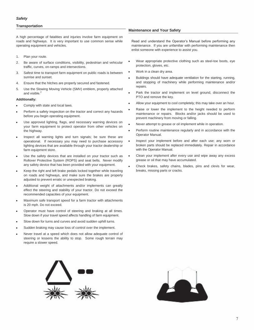
Transportation
A high percentage of fatalities and injuries involve farm equipment on
roads and highways. It is very important to use common sense while
operating equipment and vehicles.
1. Plan your route.
2. Be aware of surface conditions, visibility, pedestrian and vehicular
traffic, curves, on-ramps and intersections.
3. Safest time to transport farm equipment on public roads is between
sunrise and sunset.
4. Ensure that the hitches are properly secured and fastened.
5. Use the Slowing Moving Vehicle (SMV) emblem, properly attached
and visible.2
Additionally:
Comply with state and local laws.
Perform a safety inspection on the tractor and correct any hazards
before you begin operating equipment.
Use approved lighting, flags, and necessary warning devices on
your farm equipment to protect operator from other vehicles on
the highway.
Inspect all warning lights and turn signals; be sure these are
operational. If necessary you may need to purchase accessory
lighting devices that are available through your tractor dealership or
farm equipment store.
Use the safety devices that are installed on your tractor such as
Rollover Protective System (ROPS) and seat belts. Never modify
any safety device that has been provided with your equipment.
Keep the right and left brake pedals locked together while traveling
on roads and highways, and make sure the brakes are properly
adjusted to prevent erratic or unexpected braking.
Additional weight of attachments and/or implements can greatly
effect the steering and stability of your tractor. Do not exceed the
recommended capacities of your equipment.
Maximum safe transport speed for a farm tractor with attachments
is 20 mph. Do not exceed.
Operator must have control of steering and braking at all times.
Slow down if your travel speed affects handling of farm equipment.
Slow down for turns and curves and avoid sudden uphill turns.
Sudden braking may cause loss of control over the implement.
Never travel at a speed which does not allow adequate control of
steering or lessens the ability to stop. Some rough terrain may
require a slower speed.
Maintenance and Your Safety
Read and understand the Operator’s Manual before performing any
maintenance. If you are unfamiliar with performing maintenance then
enlist someone with experience to assist you.
Wear appropriate protective clothing such as steel-toe boots, eye
protection, gloves, etc.
Work in a clean dry area.
Buildings should have adequate ventilation for the starting, running,
and stopping of machinery while performing maintenance and/or
repairs.
Park the tractor and implement on level ground, disconnect the
PTO and remove the key.
Allow your equipment to cool completely; this may take over an hour.
Raise or lower the implement to the height needed to perform
maintenance or repairs. Blocks and/or jacks should be used to
prevent machinery from moving or falling.
Never attempt to grease or oil implement while in operation.
Perform routine maintenance regularly and in accordance with the
Operator Manual.
Inspect your implement before and after each use; any worn or
broken parts should be replaced immediately. Repair in accordance
with the Operator Manual.
Clean your implement after every use and wipe away any excess
grease or oil that may have accumulated.
Check brakes, safety chains, blades, pins and clevis for wear,
breaks, missing parts or cracks.
Safety

Safety Labels
Your Litter Saver comes equipped with all safety labels in place.
Their placement is designed to help you safely operate your Litter
Saver. These safety decals are not substitutes for reading and under-
standing this Operator’s Manual.
1. Read and follow their directions.
2. Keep all safety labels clean and legible.
3. Replace all damaged or missing labels. To order new labels go
to your nearest Priefert Ranch Equipment dealer.
4. Some new equipment installed during repair requires safety
labels to be affixed to the replaced component as specified by
Priefert. When ordering new components make sure the correct
safety labels are included in the request.
5. Refer to diagram below for proper label placement.
Replacing Labels
To install new labels:
1. Clean the area the label is to be placed.
2. Spray soapy water on the surface where the label is to be placed.
3. Wipe the surface dry.
4. Peel backing from label.
5. Press firmly onto the surface.
Use a small straight edge plastic (credit card) to squeeze out air bub-
bles working from the center out towards the sides.
Safety
8

Section 1: Set-Up Requirements
This unit is shipped completely assembled. Carefully follow instructions
for Hook-up and Driveline installation. Hitch clevises and lock pins are
sold separately.
Tractor Requirements
This implement is designed with a 3-Point category I and II hitch.
Horse power rating of the tractor should not exceed the PTO rating of
the gearbox.
Three-Point Hitch
See Chart below for Tractor Categories and Three-Point Standards
The lower link arms are the 2-steel or cast arms that extend rearward
and provide the lift and are the pull-point for the implement. The Upper
Link is the 3rd mounting point and extends from a top middle position at
the rear of the tractor. Comparatively little rearward force is applied
from the top link. Adjust the tractor’s top link to place the upper hitch
vertically above the lower lifting arms.
Tractor Hook-Up
1. If your tractor has a multi-speed PTO, be certain that the PTO is
set for 540 RPM.
2. Back tractor up to implement until lower 3-point links are aligned
with the hitch clevises on your implement. Always stop the tractor,
set the brake, shut off engine and remove the key before
dismounting from tractor.
3. As you hook the Litter Saver to the tractor, be sure to secure two
stabilizer bars in conjunction with lift arms to machine. Stabilizer
bars must be used to prevent damage to the machine, and to
maintain the proper positioning of the Litter Saver. Side to side
oscillation of about 2 inches is recommended.
4. Secure the tractor’s top link to the implement’s top hitch using a
3/4” hitch pin (supplied by customer). Adjust the tractor top link in
order to level the implement.
5. Install the driveline to determine if this needs to be adjusted. Page
11 covers driveline adjustments.
Leveling Implement
1. After attaching the Litter Saver to tractor, start tractor. Locate level
area to lower machine flat, with skids level. Adjust top link of three-
point hookup to attain snug adjustment to maintain level machine.
Occasionally, more adjustment may be needed on top link to
create an angle for skid to dig into hard cake.
2. The hammers must be the same height from the ground on both
sides of the implement for optimal performance.
3. Carefully raise and lower the implement to ensure that tractor's
tires, drawbars, and other equipment on the tractor do not come
into contact with the implement's frame or PTO Driveline.
4. Use the lift control limiting stop on the tractor control lever to
limit the upward travel of the lever so the lift cannot be raised
high enough to cause contact between the drive shaft shield
and front shielding.
Model
Width
Gear Box HP Rating
Tractor HP Rating
LS5 5’ 75 HP 40-75 HP
LS7 7’ 75 HP 60-75 HP
3Tractor Categories and Three-Point Hitch Specifications
Category
Hitch Pin Size Lower Hitch Spacing (Spread)
Horsepower Rating
Lower Link Upper Link
Inches Metric Inches Metric Inches Metric HP kW
I
3/4”
19mm
7/8”
22.4mm
26”
718mm
Up to 45
Up to 35
II
1”
25.5mm
1-1/8”
28.7mm
32”
870mm
Up to 100
Up to 75
III
1-1/4”
31.75mm
1-7/16”
37.4mm
38”
1010mm
Up to 225
Up to 168
9

Driveline Installation
Refer to Figure 1-1 Coupling
Your Litter Saver driveline is connected with a push pin coupling to the
tractor and a pull collar attached to the gearbox on the implement. To
minimize torque on the driveline when starting up, remember to always
engage the PTO at a low engine RPM.
CAUTION
Tractor PTO shield and all implement guards must be in place
at all times during operation!
DANGER
Priefert advises against the use of PTO adapters as these
may defeat the purpose of the master shield on your tractor.
PTO adapters create an unguarded shaft area between the tractor
and the driveline guards that may cause entanglement that may
result in serious injury or death.
DANGER
Do not attempt to operate your PTO driveline while it is
unguarded as this may cause entanglement that can result in
serious injury or death.
IMPORTANT: If you are switching tractors or going to use a quick
connect hitch then you will need to check the driveline maximum and
minimum lengths to ensure the safe operation of your equipment. You
may find it necessary to use different drivelines.
NOTE: Before connecting the PTO Drivelines, clean and lubricate
driveline connection points. When checking PTO driveline minimum
length, it is important to have the tractor’s PTO driveline level with the
implement’s gearbox shaft. Engage the tractor’s hydraulic 3-point to
raise or lower the lower arms until the implement’s gearbox shaft is level
with the tractor’s PTO Shaft.
IMPORTANT: Before you begin the driveline adjustments, Priefert
strongly recommends that you request your dealer to fit your driveline to
your equipment. Priefert does not recommend modifications to our
products. If it is necessary to shorten the driveshaft, we recommend
that you contact your implement dealer for service.
PTO Driveline:
Refer to Figures 1-2 to determine minimum and maximum
operating lengths on page 11.
The PTO driveline minimum and maximum lengths must be checked
prior to initial use or when using a different tractor or adding a quick
connect hitch as well as to ensure that the driveline is compatible with all
work conditions required by your Priefert implement.
When fully extended the driveline must have a minimum overlap of the
inner and outer shafts of not less than 1/3 the free length with both inner
and outer shafts being of equal length or not less than a 6” (76mm)
overlap.
Telescoping drivelines will have a variant in lengths due to changes in
the vertical angle of +20o due to uneven terrain or raising implement for
transport. It is very important not to operate your driveline with less than
the 1/3 free length or 6” (76mm) overlap as this may cause your
driveline to detach while in operation and pose a safety hazard to the
operator and possible damage to the tractor and implement.
1. Attach implement to your tractor.
2. Adjust tractor top link until the implement gearbox input shaft is
level with tractor input shaft.
3. Place tractor gear selector into park, turn engine off, set park brake
and remove key.
4. Securely block implement in this position.
5. Attach the PTO driveline to the implement’s shaft by sliding the
Push-Pin coupling of driveline over the splined input shaft of the
gearbox. Secure with driveline yoke locking device.
6. Slide the opposite driveline yoke end over the tractor’s splined
driveline shaft. Secure with driveline yoke locking device. The
driveline will require shortening if it is too long to fit between the
tractor and implement. Contact your Dealer to have the proper
adjustments made.
Determine your operating lengths:
1. Pull drive halves apart until fully extended, just before coming
apart. Record this measurement as A and subtract 6” (76mm) and
record as C measurement in your operator’s manual.
2. Push the driveline halves together. Record this measurement as B
and add 1” (25.4 mm) and record as D measurement in your
operator’s manual.
IMPORTANT: Never operate equipment with driveline extended
beyond measurement C. Never operate equipment with driveline
collapsed to less than measurement D.
Section 1: Set-Up Requirements
10
A. Push Pin Coupling
B. Pull Collar Coupling and shear bolt protection
Fig 1-1 PTO Coupling (Safety chains not shown for clarity)
B
A

Dealer Instructions for Driveline Adjustment
Refer to Figures 1-2 for minimum and maximum lengths.
IMPORTANT: Adjusting the PTO Driveline requires that all cuts be
made equally to the inner/outer guards and the inner/outer shafts.
1. Remove the PTO driveline from the tractor’s splined output shaft
and the implement’s splined gearbox.
2. Pull the inner and outer shafts apart.
3. Remove the PTO shields (guarding).
4. Attach the implement’s inner cylinder to the implement’s gearbox
shaft.
5. Pull on the implement’s PTO driveline to ensure that it is securely
attached.
6. Attach the tractor’s output shaft to the tractor’s gearbox shaft.
7. Pull on the tractor’s PTO driveline to ensure that it is securely
attached.
8. Raise and lower implement to find the shortest operating distance
between the gearbox input shaft and tractor’s output shaft.
9. Hold both halves parallel to each other in the shortest operating
distance and mark them.
10. Measure the marks made in Step 9 and record them to shorten the
outer and inner guards equally.
11. Raise and lower implement to find the maximum operating distance
between the gearbox input shaft and tractor’s output shaft.
12. Hold both halves parallel to each other in the maximum operating
distance and mark them.
13. Check that the driveline has a minimum of 6” (152.4mm) overlap or
1/3 the total length of the driveline.
14. Measure the marks made in Step 13 and record them.
15. Disconnect the implement inner cylinder from the implement’s
gearbox shaft.
16. Disconnect the tractor’s output shaft from the tractor’s gearbox shaft.
17. Securely clamp the implement driveline guard shield section in a
vise and cut off the guard at mark. File off any burrs. Repeat this
step for the tractor driveline guard shield. Use one of these
sections to create a cutting guide for the shaft and cylinder.
18. Use a padded vise to securely clamp the implement cylinder.
Do not over-tighten or damage the cylinder may occur.
19. Using the guard guide, mark the cylinder and cut. File any burrs and
clean off filings. Do not round the ends of the cylinder when filing.
20. Repeat steps 12 and 13 to shorten the tractor driveline shaft.
21. Apply grease to the inner shaft.
22. Reassemble the driveshaft, and securely attach the driveline guard
and reattach the PTO driveline to the tractor and implement. Make
sure that these are securely attached before attempting to engage
the PTO driveline.
23. The driveline should now be moved back and forth to insure that
both ends are secured to the tractor and implement. Reattach any
end that is loose.
24. Hook driveline safety chain in the hole in the inner driveline guard.
Attach the other end to the implement’s main frame.
25. Hook driveline safety chain in the hole in the outer driveline guard
and attach the other end to the tractor main frame.
26. Start tractor and raise implement just enough to remove blocks
used to support the implement frame.
27. Slowly engage tractor’s hydraulic 3-point to lower the implement.
Check for sufficient drawbar clearance. Move drawbar ahead,
aside or remove if required to eliminate binding.
28. Check to make certain that the driveline overall length does not
extend beyond the maximum recorded length as in Step 14.
CAUTION
Incorrectly fitted safety chains will result in excessive tension
causing the safety hook to open on the protection side. If this
occurs it is necessary to replace damaged hook with an original one.
This chain must be attached to the inner driveline shield and to the
implement to restrict shield rotation.
Measurements:
11
Section 1: Set-Up Requirements
Fig 1-2 Checking Minimum and Maximum Lengths

12
Section 2: Operating Instructions
Operating Check List
Hazard control and accident prevention are dependent upon the
awareness, concern, and proper training involved in the operation,
transport, maintenance and storage of the Litter Saver. Therefore, it is
absolutely essential that no one operates the Litter Saver without first having
read, fully understood and become totally familiar with the Operator’s
manual. Make sure the operator has paid particular attention to:
Safety, pages 5-8
Section 1: Set-Up Requirements, pages 9-11
Section 2: Operating instructions, pages 12-14
Also make sure the operator has completed the Operating Checklist
below before using the Litter Saver:
Read and follow the “Safety” section starting on page 5 carefully.
Read all of the “Operating Instructions” section on pages 14 - 18.
Review your tractor’s operating instructions.
Check the Litter Saver initially and periodically for loose bolts &
pins & chains (where applicable).
Make sure all guards and shields are in place.
Know your controls and how to stop tractor, engine and PTO
quickly in an emergency.
Inspection Procedures
Make the following inspections with Litter Saver attached to a
tractor with PTO disengaged and completely stopped:
1. Inspect tractor safety equipment to make sure it is in good working
condition.
2. Carefully raise and lower implement to ensure that drawbar, tires,
and other equipment on the tractor do not contact implement frame
or PTO driveline.
3. Check that all hardware is properly installed.
4. With implement resting on solid supports, PTO completely stopped
and disengaged, check that the hammers are intact, secure and
properly positioned.
5. Check PTO guards to make certain they are in good working
condition and in place.
6. Remove solid supports and verify implement’s front and top link
alignments,
7. Lubricate all grease fitting locations. Make sure PTO shaft slip joint
is lubricated.
8. Remove threaded plugs on gearbox to be sure gear lube runs out the
small check plug on side of the gearbox. Replace and secure plugs.
9. Reconnect tractor driveline to implement. Make sure that the
driveline operates freely and is seated firmly in the tractor PTO
shaft’s spline groove.
10. Set tractor PTO shaft and transmission into neutral before
starting engine.
11. Gradually, set tractor throttle select lever to 540 RPM.
The remaining inspections are made by engaging the PTO to check
for vibrations.
IMPORTANT: Stop PTO immediately if vibration continues after a few
revolutions during start-up and anytime it occurs thereafter. Wait for
PTO to come to a complete stop before dismounting from tractor. Make
necessary repairs and adjustments before continuing on.
Start tractor, set throttle to idle or slightly above idle and slowly
engage PTO. Initial start-up vibration is normal and should stop
after a few revolutions. Stop PTO rotation immediately if vibration
continues.
Once the implement is running smoothly, increase tractor throttle to
540 RPM. Stop PTO immediately if vibration occurs.
IMPORTANT: Do not exceed RPM rating. Excessive engine speed
will cause damage to the power train components.
Transporting
CAUTION When travelling on public roads at night or during the day, use
accessory lights and devices for adequate warning to operators or other
vehicles. Comply with federal, state, and local laws.
1. Make sure driveline does not contact tractor or Litter Saver when
raising Litter Saver to transport position. If it is necessary to lift Litter
Saver above 14”, always disconnect the tractor PTO driveline first.
Always disengage the tractor’s PTO before raising the Litter Saver
to transport position.
2. Reduce tractor ground speed when turning, lift Litter Saver and
allow enough clearance so Litter Saver does not contact obstacles
such as buildings, trees or fences.
3. Limit transport speed to 20 mph. Transport only with a farm tractor
of sufficient size and horse power.
4. Shift tractor to a lower gear and use extra care when traveling over
rough terrain.
5. When traveling on roadways, transport in such a way that faster
moving vehicles may pass you safely.
6. Sudden braking can cause equipment to swerve and upset. Keep
right and left brake pedals locked together while traveling on road
surfaces to prevent misdirected braking.
Un-hooking the Litter Saver
Unhook Litter Saver from the tractor as follows:
1. Park Litter Saver on a level solid hard surface.
2. Lower Litter Saver to level ground or onto stable support blocks.
3. Disengage power to the driveline.
4. Engage tractor park brake, shut down, and remove key before
dismounting from tractor.
5. Disconnect driveline from tractor PTO shaft.
6. Un-hook 3-point connectors from tractor.
7. Reinstall hitch pins, lynch pins and hairpin cotters in Litter Saver
hitch for storage.
8. Connect driveline safety chains together. .

13
Section 2: Operating Instructions
Operational Safeguards
IMPORTANT: Children SHOULD NOT be allowed to operate the
Litter Saver.
DANGER
Do not engage tractor PTO while hooking-up and unhooking the
driveline or while someone is standing near the driveline. A person’s
body and/or clothing can become entangled in the driveline resulting
in serious injury or dearth.
Tractor PTO shield, gearbox shield, and driveline shield must be
secured in place while operating the Litter Saver to avoid injury or
death from entanglement in rotating drivelines.
Damaged drivelines can break apart while rotating at high speeds
causing serious injury or death. Always remove Litter Saver from
service until damaged drivelines are repaired or replaced.
Never carry a passenger on the Litter Saver. A rider can fall, causing
serious injury or death.
Do not use Litter Saver to lift or carry objects. Lifting and/or carrying
objects can result in damage to the Litter Saver.
Never operate the Litter Saver while in the raised position. The Litter
Saver can discharge objects at high speeds resulting in serious injury
or death.
Do not use the housing as a working platform. The housing is not
properly designed or guarded for this use. Using housing as a
working platform can cause serious injury or death.
Do not reverse while Litter Saver is engaged. If it is necessary,
disengage the PTO drive, lift the Litter Saver from the cake or litter
and make sure that the area to the rear is clear before backing.
Never lift the Litter Saver more than 14 inches from the ground
with the PTO engaged or the driveline could break and cause
injury or death.
Rotary hammers are capable of throwing debris and objects for great
distances and inflicting serious injury. Bystanders should be made
aware of dangers. No operation of equipment should occur in
bystander's presence.
The rotating parts of this machine have been designed and tested for
rugged use. However, they could fail upon impact with heavy solid
objects such as steel guardrails, concrete footings in broiler houses,
etc, causing foreign material to be thrown at very high velocities.
Never allow the cutting hammers to contact such obstacles.
Watch for hanging obstacles such as wiring, beams, equipment, etc.,
that are normally in poultry houses. Never allow the rotating
hammers to contact such items.
WARNING
Always disengage PTO, set parking brake, shut tractor engine off,
remove switch key and wait for hammers to come to a complete stop
before dismounting from tractor.
CAUTION - Respiratory Hazard 5
When operating the Litter Saver, a respirator is REQUIRED.
An ammonia methylamine respirator is necessary. One respirator with pre-
filters accompanied your machine. These should be inspected and parts
replaced as needed. There is the possibility of lung problems as a result of
the inhalation of manure dust. A type of pneumonia can result and/or allergy
related problems. Being careful as to exposure and wearing the appropriate
mask is of utmost importance. Even with the best mask, there is no ultimate
guarantee that you will not contract diseases or illnesses associated with
inhalation of manure excrement. Operators should plan on exposure to such
organisms. Serious infections and even death can result from such
exposure. Please consult with a physician about all such medical hazards.
CAUTION - Ocular Hazard
When operating the Litter Saver, safety goggles are REQUIRED
and should be sufficient and appropriate for the job undertaken.
They should; in fact, be capable of shielding the eyes from dust, flying
particles, and some thrown objects of low impact. During operation, always
use the safety goggles which accompanied your machine, or appropriate
eye protection.
WARNING
Prior to reconditioning, inspect the floor for objects such as wire,
cable, rope, chains, etc., which can become entangled in the rotating
parts of the drum. These items could then swing outside the housing at
greater velocities than the rotating hammers, creating an extremely
dangerous condition.
Before Reconditioning:
1. Thoroughly inspect and clear the area to be pulverized for debris
and unforeseen objects. Remove any potential hazards.
2. Check that no one enters the area of operation.
3. Check all Litter Saver hammers, bolts and nuts are tight.
4. Ensure all guards and shields are in place and secure.
5. Operate with 540 RPM PTO tractor.

14
General Operating Instructions
Litter Savers are designed to pulverize cake and lift litter in poultry
houses & broilers, allowing ammonia to escape. Generally suitable for
standard bedding materials, the Litter Saver levels with each pass,
without digging into the hardpan.
With proper care, including cleaning, maintenance and adequate
storage, the Litter Saver will provide maximum use and operation.
The following pages contain information to obtain the best operational
results from your Priefert Litter Saver.
It is important that you understand the Operator’s manual, completed
the Operator’s Checklist, properly attached Litter Saver to your tractor,
made leveling adjustments, and preset your angle and height before
beginning a running operational safety check on your Litter Saver.
Before starting the tractor ensure the park brake is engaged, the PTO is
disengaged, and the Litter Saver is resting on the ground.
WARNING
Prior to machine operation, the operator needs to be equipped
with respirator, safety glasses, and hard hat.
Locate level area to lower machine flat, with skids level. Adjust top link
of three-point hookup to attain snug adjustment to maintain level
machine. Occasionally, more adjustment may be needed on top link to
create an angle for skid to dig into hard cake.
NOTE: Do not allow the Litter Saver to drop violently on the ground.
Lower it slowly to allow the hammers to gradually begin to recondition
the cake. Violent impacts would strongly stress all machine components
and could cause serious damage to the Litter Saver.
Drive into house and position tractor and machine in right-hand
corner to start.
Idle tractor at 540 RPM. Engage PTO. When ready to begin
reconditioning of the cake, operate at 1600 - 1800 RPM on tractor
tachometer.
Start in low gear mainly to check operation. Then run at adjusted speed
and gear to keep machine approximately half full of litter. Path of travel
should be along outside walls, reconditioning toward center of house,
with each pass becoming smaller than previous. Refer to illustration for
proper direction of travel and route for effective renovation.
Hinged rear door should be adjusted to adequately discharge litter. This
depends mostly on the wetness or thickness of the cake. If litter is 3"- 8"
thick, rear door should be open at maximum chain linkage during entire
operation. After first flock and/or entirely cleaned outhouse, door should
be closed to no more than 2" opening with chain.
WARNING
Never operate with hinged rear door opened back against main
frame and not chained. Disastrous injuries or death could result from
improper operation.
Wetness of the litter, temperature, wind condition, and humidity will
cause a variation in the number of applications (runs). In most cases,
3-4 runs with 8 hour intervals, should be adequate.
During and after using the machine, the drum should be inspected for
foreign debris such as used cable, wire, rope, etc., that may have
accumulated. Remove all such debris after disengaging the PTO.
DANGER
DO NOT clean machine unless PTO is disengaged, tractor is
turned off and key is removed from ignition.
In the event you do strike a foreign object, disengage the PTO, stop the
Litter Saver and tractor immediately to inspect and make necessary
repairs to the Litter Saver before resuming operation.
Route for Poultry House Renovation
Refer to Figure 2-2
Before backing into corners for renovation, raise machine out of litter.
Renovation should only be done while traveling forward in a straight line.
The rotation, design, and position of the hammers plus the direction of
travel is important in the successful operation of the Litter Saver.
Remember to look back often.
Section 2: Operating Instructions
Fig 2-1 Route for Renovation

15
Service
Proper servicing and adjustment is the key to the long life of any Litter
Saver. With careful inspection and routine maintenance, you can avoid
costly down time and repair. Do not get under the machine to make
measurements or adjustments without securely blocking Litter Saver first.
DANGER
Always disengage main driveline from tractor PTO before servicing
the underside of the Litter Saver. Litter Saver can be engaged if tractor is
started resulting in damage to the equipment and serious injury and/or
death.
1. Check all bolts after each use.
2. Replace any worn, damaged or illegible safety labels by obtaining
new labels from your Priefert Dealer.
3. Before you add oil to the gearbox, it is important that the fill plug area
be wiped clean before removing plugs. Debris mixed into the
lubricants will rapidly wear the parts and destroy bearings and gears.
Oil levels must be checked when Litter Saver is on a level surface.
If your Litter Saver is operating in a heavy duty working capacity then
maintenance operations may need to be performed more frequently.
WARNING
Always secure Litter Saver deck in the up position with solid
supports before servicing the underside of the Litter Saver. Never work
under equipment supported by hydraulics; fluid pressure can equalize
allowing supported attachments to fall. Hydraulics can drop equipment if
controls are actuated or if hydraulic lines burst. These conditions exist
even when power to the hydraulics is shut off.
Lubrication Intervals and Maintenance
1. Outboard drum bearing assembly - Refer to Figure 3-1:
There is one grease zert on the bearing assembly which is located
on the right outer-side of the Litter Saver. This fitting should be
greased with multipurpose grease on a daily basis.
2. Gear Box:
Remove the two threaded plugs and fill top opening with 90-weight
gear oil. When oil begins to run out of the lower opening, fluid level
is full. Replace plugs and secure them. Under normal use, this
should be done 2 to 3 times annually. With extreme use, it should
be done weekly.
3. Driveshaft - Refer to Figure 3-2:
After periods of inactivity, grease the drive shaft before putting into
operation. Lube intervals include the cross, bearing tractor end,
bearing implement end, shear pin, CV joint, and yoke joints.
Lubricating
Lubricate all fittings with a good quality lithium soap compatible with E.P.
Grease meeting the N.L.G.I. #2 Specifications and containing no more
than 1% Molybdenum Disulfide.
While greasing any internal greasing system, use the special zert nipple.
Grease slowly, giving time for the grease to flow along the tubes.
Internal rotating guard bushings should be lubricated upon replacement.
Continued and Preventative Maintenance
The life of the machine depends on the care taken. When machine is to
be stored, and after each operation, certain things should be done. The
machine should be washed, the driveline should be greased, and the
outboard drum bearing should be greased (located on outside, right side
of machine). For proper care, the machine should rest on blocks while
being stored for any length of time.
Oil to be used in gearbox is 90wt. The drive shaft needs greasing
approximately every 8 hours of operation.
The drive shaft is equipped with a shear bolt torque limiter. This is on
the gearbox end of the drive shaft. (Fig 1-1) To prevent major damage
to the drive shaft, a bolt will shear itself, permitting shaft to turn, but not
permitting gear or drum to turn nor become damaged.
If this machine is used for anything other than its intended use, only as
described in Priefert's published brochures and advertisements, all
warranties are voided. Gearbox and drive shaft are warranted separate
and apart from Priefert's warranty and the user is referred to the
provisions of the gearbox and drive shaft manufactures warranty.
See page 22 for specific warranty coverage.
Section 3: Maintenance
Components
Hourly Usage
U-Joints (B)
Multi-purpose grease 4 to 6 lever pumps
8 Hours
Cross (aka Spider) (B)
8 Hours
Guard Bearings /Bushings (B)
8 Hours
Telescoping Profile Tubes (D)
Multi-purpose grease 8 to 10 lever pumps
20 Hours
Outer Tube Coupler (A)
Before
Each Use
Multi-purpose grease
Inner Tube Coupler (C)
Fig 3-2 Driveline Lubrication
A A
B C
D
Fig 3-1 Outboard Drum Bearing Lubrication
Reminder:
Grease Daily
Grease Zert

16
Section 3: Maintenance
Repair and Replacement
For most part replacements and/or repairs, the· job is made easier by
rolling the main frame so it will rest on its backside. This provides easier
access to each part. All service and/or repair should only be handled by
a skilled individual with prior mechanical training. No alterations should
be made and all replacement parts should be ordered from Priefert
Manufacturing, or authorized distributors. Alterations or substandard
parts may void the warranty.
Outside Flange Bearing - Refer to Figure 3-2.
1. Using two wrenches,
one for backup holding,
take four bolts and lock
nuts out of bearing
assembly that holds it
to main frame.
2. Loosen the two set
screws on bearing with
an appropriate size
allen wrench. Pull
entire bearing assembly
off drum shaft, keeping
in mind to support drum
assembly while doing this
procedure. After bearing
is off, let drum rest in the
hole where positioned.
If pry device or pull
dev ice i s needed
to remove bearing assembly from drum shaft, do so with care.
Hub and Drum - Refer to Figure 3-3.
1. Using two wrenches, one for backup holding, loosen and take out
bolts and lock nuts that hold drum and hub together. Due to the
tight working space, loosen bolts and nuts holding gearbox to main
frame. Do not take bolts and nuts completely out at this point.
This will provide support to gearbox, yet permit freedom of
movement to remove drum. This procedure will produce additional
space to maneuver drum past hub for removal.
2. With assistance and care, slide drum past hub end and slide out of
main frame. Carefully lay drum down on chosen work surface,
remembering that hammers can make resting position awkward.
3. Now remove cotter pin which secures castle nut. Using a suitable
wrench on drive shaft side of gearbox to prevent turning, loosen
and remove castle nut. Also, remove flat lock washer. With
appropriate pulling or pry device, remove hub from gearbox shaft.
Carefully place aside.
Gearbox - Refer to Figure 3-4 below.
1. Once drum and hub have been removed (previous procedure),
finish removing bolts and nuts holding gearbox to main frame.
During this procedure, be prepared to support gearbox for removal
due to weight. Carefully set gearbox aside.
Hammers - Refer to Figure 3-5.
1. Using two wrenches, one for backup holding, loosen and remove
bolts and lock nuts from assembly position, and slip nylon bushing
out of the enclosure of hammer.
2. It is important to note that upon reinstallation of hammers, they
be positioned so as to have a forward action. Since the drum
rotates toward the tractor in clockwise direction, the cutting or
pulverizing end of the hammer, when on the tractor side of
drum, will be curved toward the ground. A simple way to help in
this procedure will be to remember how and at what position
they were removed. Do not over-tighten. Hammers should
swing freely. Refer to Parts List on page 19 for an exploded view
showing hammer direction and drum rotation.
Fig 3-2 Outboard Drum Bearing
Set Screws
Fig 3-3 Hub and Drum
Fig 3-4 Gearbox Removal
Fig 3-5 Hammer Replacement

17
LS5 LS7
Overall Width 78" 106"
Working Width 60" (5 ft.) 84" (7 ft.)
Overall Depth 44" 44"
Weight 595 lbs 876 lbs
Number of Hammers 26 38
Gearbox 75 HP ; 1: 1.46 ratio
Side Gearbox
Lubrication EP 00 or 000 Flowable Grease; Capacity 63 oz.
Rotor Shaft Speed 788 RPM Hub @ 540 RPM PTO
Recommended
Maximum PTO HP 40 HP-75 HP 60 HP - 75HP
Driveline Shielded Series 5 PTO
Driveline Safety
Protection Shear Bolt
Hitch Type Designed for Category I hookup. Can fit Category II with tractor adjustment.
Respirator Type NIOSH approved against ammonia, methylamine or formaldehyde (3M #5206, supplied)
Goggles Direct-Vent Cover Goggle w/polycarbonate lens (Sellstrom Model #88010, supplied)
SPECIFICATIONS SUBJECT TO CHANGE WITHOUT NOTICE
Maintenance Record
Section 4: Specifications

18
Section 5: Parts List
Decals
Part Number Description Quantity
D120 DECAL WHITE OVAL PRIEFERT 1
D125 DECAL NOTICE ALTERATION/MODIFICATION 1
D133 DECAL DANGER ROTATING DRIVELINE 1
D135 DECAL MADE USA/GOD TRUST W/FLG 1
D225 DECAL WARNING NO RIDERS 4
D240 DECAL DANGER ROTATING BLADE HAZARD 1
D310 DECAL WARNING STAY CLEAR OF ROTATING PARTS 3
D950 DECAL ALUMINUM LS SERIAL TAG (Not Shown/ Not Replaceable) 1
DLARGE DECAL LARGE PRIEFERT 2000 (Not Shown) 21
D120 D125 D133
D135 D225 D240 D310

19
Ref Part # Description Qty
NS FM032 COTTER KEY 3/16 X 2 ZP 1
NS FM04LP LYNCH PIN 1/4 ZP 1.25 EFFECT 1
NS FM07LP LYNCH PIN 7/16 ZP 1.5 EFFECT 2
1 HUBASLYM HUB ASSEMBLY ONLY 1
2 IP200 IMPLEMENT PIN 7/8 WITH NUT 2
3 LS5W LS 5' SKIN ASSEMBLY 1
3 LS7W LS 7' SKIN ASSEMBLY 1
4 LSB LS BUSHING FOR HAMMER (5' / 7') 26/38
5 LSDRIVE-32 PTO DRIVE SHAFT 32" 1
6 LSDRUM5 5' DRUM FOR LITTER SAVER 1
6 LSDRUM7 7' DRUM FOR LITTER SAVER 1
7 LSGEAR GEARBOX 75 HP 1:1.46 RATIO 1
8 LSHAMMER HAMMERS FOR ROTATING DRUM (5' / 7') 26/38
9 UCF20824 BEARING 1-1/2 FLANGE BLOCK, UC 1
Section 5: Parts List
Part # Description Qty
FB081.50BKG5 BOLT 1/2 X 1-1/2 G5 BK REP 4
FB083.00BKG5 BOLT 1/2 X 3 G5 BK (5' / 7') 26/38
FB091.25BKG5 BOLT 9/16 X 1-1/4 G5 BK 6
FB101.50ZPG5 BOLT 5/8 X 1-1/2 GS ZP 4
FB122.50ZPG5 BOLT 3/4 X 2-1/2 G5 ZP 4
FN09NYLN NUT 9/16 NYLOCK ZP 6
FN10ASLN NUT 5/8 ALL STLLOCK NUT ZP 4
FN12NYLN NUT 3/4 NYLOCK ZP 4
FR02 POP-RIVET 1/8 X 1/8 ALUMINUM 2
NS LSGOGGLE GOGGLES 1
NS LSRESP RESPIRATOR AMMONIA/METHYLAMINE 1
NS 501 RETAINER FOR PRE-FILTER 1
NS 5N11 DUST/MIST, PRE-FILTER 1
NS - ITEM NOT SHOWN IN THIS ILLUSTRATION
9
8
6
4
2
3
7
1
5

Section 7: Appendix
20
Troubleshooting Drivelines
Troubleshooting Gearbox
Troubleshooting Litter Saver
Problem Common Cause(s) Remedy
Wear of universal joint connection points
Excessive Working Angle Reduce working angle.
Do not attempt turns - disengage PTO and raise Litter Saver when executing
turns or backing.
Bent/Twisted universal joint connection points
Excessive Torque Peak or Shock Load Avoid overloading and engaging drive under load
Check PTO clearances with Tractor drawbar, etc.
Separated Telescoping Tubes Excessive Extension of Driveline Avoid excessive extension of driveline.
Check extension of drawbar hitch according to this manual.
Deformation of Telescoping Tubes
Excessive Torque Peak or Shock Load Avoid overloading and engaging drive under load.
Check that driveline does not come into contact with tractor or implement
during operation.
Accelerated Wear of Telescoping Tubes or Shield Bearing
Insufficient Lubrication Follow maintenance instructions on page 15.
Insufficient Tube Overlap - Refer to Driveline Installation, pages 10-11.
PTO Vibrates
Worn Universal Joint.
PTO Driveline Bent.
PTO driveline hitting front of tiller or swinging drawbar.
Replace Universal Joint.
Replace PTO Driveline.
Adjust machine lift height and/or remove drawbar.
Problem Common Cause(s) Remedy
Gearbox Overheating Low on lubricant.
Improper type of lubricant.
Excessive debris build-up around gearbox.
Fill to proper level.
Replace with proper lubricant.
Remove debris.
Gearbox Noisy Rough Gears.
Worn Bearings.
Low oil in gearbox.
Run in or change gears.
Replace bearing.
Check level and add oil.
Gearbox Leaking Damaged oil seal.
Bent shaft.
Shaft rough in oil seal area.
Oil level too high.
Hole in gearbox.
Gasket damaged.
Bolts loose.
Improper type of lubricant.
Replace seal.
Replace oil seal and shaft.
Replace or repair shaft.
Drain oil to proper level.
Replace gearbox
Replace gasket.
Tighten bolts.
Replace with proper lubricant.
Gearbox Clicking Gearbox gear tooth damaged. Replace damaged gear.
Problem Common Cause(s) Remedy
Excessive Vibration Improper or misaligned connection to tractor.
Damaged or missing Hammers.
Excessive debris around Drum or Hub assembly.
Check connections - Refer to Tractor Hook-Up, page 9.
Repair or replace Hammers.
Remove debris.
Poor reconditioning results of cake Insufficient RPM of Drum.
Worn, damaged or missing Hammers.
Hanging rear door closed
Insufficient number of passes.
Increase RPM to proper operation speed - Refer to page 14.
Repair or replace Hammers.
Open door to allow increased discharge of litter
Repeat process - Refer to page 14.
Implement Noisy Excessive debris around Drum or Hub assembly.
Damaged or missing Hammers.
Attempting turns or backing without lifting implement.
Remove debris.
Repair or replace Hammers.
Do not attempt turns - disengage PTO and raise Litter Saver
when executing turns or backing

Guide to Litter Management Utilizing the Priefert Litter Saver
The key to reducing ammonia is dry litter. In addition, dry litter
saves fuel cost and provides a soft, comfortable bed for new chicks.
Pathogens are greatly reduced by removing the dampness that allows
them to thrive.
In order to prepare for the best possible performance, it is
recommended that houses be partially cleaned to the floor each spring;
usually from feed line to feed line, depending upon your configuration.
This procedure removes excessive heat for summer flocks and, by
reducing depth, allows for quick dry outs. By late fall, litter depths will
have increased to the point of providing additional heat that can reduce
winter fuel costs. With regular use of the Priefert Litter Saver, hard pan
is eliminated and fast, thorough clean outs are made easier.
Each pass in the broiler house improves the litter condition up to a
point of least return. Therefore, the number of passes required
depends upon the moisture level of the litter, amount of lay-out time,
temperature and humidity. Under average conditions, up to 3 passes
on 8 hour intervals may be suitable. If quick turnarounds are expected,
every day counts. Therefore, it may be recommended that the operator
begin the conditioning process as soon as possible; even while the
additional houses are being caught.
Summer Guidelines
Summertime management is tempted to forego the intensive follow
through necessitated by cold weather. Nevertheless, it is incumbent
that management take advantage of warm days and use the
opportunity to more easily occupy the top percentile of settlements.
Begin the first pass by placing the adjustment chain in the last rung and
lowering the bottom skids to the dirt. Run your tractor to achieve 540
PTO RPM, using low range and first gear depending upon your
tractor’s horsepower and gear ratio. Drive as close to the wall as
possible. If time allows during the first pass, don’t be afraid to overlap
each round. You will have time later to adjust the litter ridges so that
they fall between the feed and water lines. Now is a good time to use
the garden rake to pull the cake (or cookies) about 18 in. from the wall
toward the center. If time is on your side, allow an entire day for the
first round of fan drying. In the typical 40’ x 500’ house, 2 or 3 large
fans are sufficient. Close all vents and doors and open the pad end to
accommodate air flow. If the nights are extremely high in humidity, you
should consider turning off the fans from sunset to sunrise.
On the second and all additional passes, the Litter Saver skids should
bottom out on the dirt pad. You might consider moving approximately
6” away from the wall and moving up another gear level.
Before beginning the remaining passes, shorten the chain to
approximately 9 links. This will allow the remaining semi-dried cake to
be pulverized 1 to 3 times as the litter is now forced to circle in the tank
multiple times. In the interest of time, cost, and providing a smooth
surface, it would be wise to adjust each pass by locating a wire, pipe,
or whatever you can use to maintain a straight line and allow the outer
ridge of litter to fall between the water and feed lines. The size of your
Litter Saver (5’ or 7’) and the width of the house will determine the
number of rounds needed to complete one pass. With a little
experience, you will learn how long is needed before each succeeding
pass. Initially, allow 8-24 hours until you learn what is right for various
environmental conditions and litter depth. (Note: Oftentimes when
encountering deep litter (5-10”), you will notice a stress on the Litter
Saver brought about by overload. When this occurs, slowly raise the 3
pt. hitch until it runs smoothly, and then slowly lower the 3 pt. hitch
back to your original setting.)
Winter Guideline
Winter management is often the greatest challenge. Cold, damp
weather is not conducive to drying, and these conditions often produce
excessive cake and wetness. Most days provide above freezing
temperature, and it is incumbent upon management to be especially
alert to take full advantage of low humidity days; utilize fans in a similar
way you would in the summer months. When this becomes impossible,
you must rely on side vents, especially in the brood section, to create
high static pressure (say 10) and set the temperature to approximately
45 degrees. This should cause a downward flow of air and aid in
producing the best possible job of drying the center brood. Attempt to
obtain an equal flow of air out of both ends of the broiler house; this will
allow equal drying of the entire house. By setting temperatures to
approximately 45 degrees, you can provide a means of at least
removing ammonia at night.
The procedure for using the Priefert Litter Saver is identical to the
summer routine with the exception of possibly doubling the time
between passes.
The Priefert Litter Saver is a management machine used to condition
litter. Remember, manufacturing recommends a minimum of
3 passes through the house. Depending upon your litter moisture,
more passes could be required. NEVER use a litter saver a day or
two before getting new chicks. There WILL NOT be adequate time to
ventilate the ammonia.
As with all equipment, proper management is the key to success!
21

22
Limited Warranties: Priefert Manufacturing Company, Inc., (“Priefert”) 2630 South Jefferson, P.O. Box 1540, Mount Pleasant, TX 75456-1540, warrants for one (1) year from the purchase date to the original non-commercial, governmental, or municipal purchaser (“Purchaser”) and warrants for six (6) months to the original commercial or industrial purchaser (“Purchaser”) that the product purchased are free from defects in material or workmanship. Priefert will replace or repair, free of charge to the original purchaser any part(s) found, upon examination at our factory, to be defective under normal use and service due to defects in material or workmanship, provided that the original purchaser: a. Notifies Priefert in writing of any defect in material or workmanship within the above specified warranty period. b. Returns must be routed through an authorized Priefert dealer or distributor from whom the purchase was made. c. Purchaser is responsible for cost of shipping. In no event will Priefert be held liable under this warranty unless written notice is received and failure must have occurred within the warranty period. Genuine Priefert replacement parts and components will be warranted for 90 days from date of purchase, or the remainder of the original equipment warranty period, whichever is longer. This limited warranty does not apply to any part of the product which has been subjected to improper or misintended use, negligence, alteration, modification, or accident, damaged due to lack of maintenance or use of wrong oil or lubricants, or repairs that have been made with parts other than those obtainable through Priefert, or which has served its usual life. This limited warranty does not apply to any expendable item such as blades, shields, guards, or pneumatic tires, or other trade accessories since these items are warranted separately by their respective manufacturers, except as specifically noted in your Operator’s Manual. Except as provided herein, no employee, agent, Dealer, or other person is authorized to give any warranties of any nature on behalf of Priefert. Only Priefert is authorized to make any representation to the purchaser concerning “normal” use and service for its product as described in the Operator’s Manual, or in authorized printed materials or stickers affixed to the product. If after examination of the product and/or part(s) in question; Priefert finds them to be defective under normal use and service due to defects in material or workmanship,
Priefert will:
1. Repair or replace the defective product or part(s); if Priefert has made several reasonable number of attempts in repairing the
product and/or part(s) to conform to the warranty; then 2. Priefert will replace part(s) or product. 3. Purchaser is responsible for any labor charges exceeding a reasonable amount as determined by Priefert and for returning
product and/or part(s) to the Dealer, whether or not the claim is approved. Purchaser is responsible for the transportation cost for the product or part(s) from the Dealer to the factory.
The choice of remedy shall belong to Priefert. Repair or replacement are the only remedies against Priefert under this limited warranty.
Limitation of Liability: 1. Priefert disclaims any express (except as set forth herein) and implied warranties with respect to the product including, but not
limited to, merchantability and fitness for a particular purpose. 2. Priefert makes no warranty as to the design, capability, capacity, or suitability for use of the product. 3. This warranty shall not be interpreted to render us liable for injury or damages of any kind or nature to person or property.
Priefert will not be liable for any special, incidental or consequential damages based upon breach of warranty, breach of contract, negligence, strict tort liability, or any other legal theory. Such damages include but are not limited to loss of crops, loss of savings or revenue, cost of capital, loss of use of equipment, facilities or services, down time, expense or loss incurred for labor, supplies, substitute machinery, rental, and claims of third parties including customers, and injury to property.
Supplementary: 1. Proper venue for any lawsuits arising from or related to this limited warranty shall be only in Titus County, Texas. 2. Priefert may waive compliance with any of the terms of this limited warranty, but no waiver of any terms shall be deemed to be
a waiver of any other term. 3. If any provision of this limited warranty violates any applicable law and is held unenforceable, then the invalidity of such
provision shall not invalidate any other provisions. 4. Applicable law may provide rights and benefits to purchaser in addition to those herein.

References
1. Sentry Insurance, FEMA, Owner’s and Operators Manuals for Farm Equipment, Sentry Insurance, Stevens Point, WI, revised Management
Bulletin No. 112, 90-42; March 2007, pp S-2.
2. Sentry Insurance, FEMA, Safety Signs for Farm Equipment, Sentry Insurance, Stevens Point, WI, 90-34, October 2006, pps 1-20.
3. American Society of Agricultural and Biological Engineers, ASABE, Three-Point Free-Link Attachment for Hitching Tillers, ASAE S217.12
DEC2001 (ISO 730-1:1994) (R2007), Printed ASABE, St. Joseph, MO. pps 1-10.
4. Occupational Safety and Health Administration (OSHA), Safety for Agricultural Equipment, 29 CFR 1928.57, http://www.osha.gov/pls/oshaweb/
owadisp.show_document?p_table=STANDARDS&p_id=10958.
5. Occupational Safety and Health Administration (OSHA), Respiratory Protection, 29 CFR 1910.134, http://www.osha.gov/pls/oshaweb/
owadisp.show_document?p_table=STANDARDS&p_id=12716.
Suggested References
Priefert assumes no liability for the use or misuse of information provided in the following references:
National AG Safety Database, NASD: 04/2002
http://www.nasdonline.org/document/905/d000745/power-take-off-pto-safety.html
Agricultural Driveline Manufacturers Association, ADMA, 2006 ADMA,
http://www.admausa.com/ptoGuardDamage6.asp
FEMA, Farm Equipment Manufacturers Association, Safety 4 Just Kids, 2008,
http://www/farmequip.org/safety
Includes AG Safety Links for additional information and materials.
Farm Safety Association, Guelph, Ontario, The Safe Movement of Agricultural Equipment on the Roadway,
http://www.farmsafety.ca/pages/manuals-dwnld.html
Farm Safety Association, Guelph, Ontario, Preventing Farm Incidents Caused by Moving Parts,
http://www.farmsafety.ca/pages/pages/manuals-dwnld.html
Occupational Safety and Health Administration (OSHA), General Respiratory Protection, OSHA Bulletin 2011,
http://www.osha.gov/dts/shib/respiratory_protection_bulletin_2011.html