Embed Size (px)
Citation preview
Available online at www.sciencedirect.com
+ MODEL
ScienceDirect
Green Energy & Environment xxx (xxxx) xxxwww.keaipublishing.com/gee
Research paper
Lithium-conductive LiNbO3 coated high-voltage LiNi0.5Co0.2Mn0.3O2
cathode with enhanced rate and cyclability
Haifeng Yu a,1, Shouliang Wang a,1, Yanjie Hu a, Guanjie He b, Le Quoc Bao c, Ivan P. Parkin b,Hao Jiang a,*
a Key Laboratory for Ultrafine Materials of Ministry of Education, Shanghai Engineering Research Center of Hierarchical Nanomaterials, School of Materials
Science and Engineering, East China University of Science and Technology, Shanghai 200237, Chinab Christopher Ingold Laboratory, Department of Chemistry, University College London, 20 Gordon Street, London, WC1H 0AJ, UK
c Faculty of Applied Sciences, Ton Duc Thang University, 19 Nguyen Huu Tho, District 7, Ho Chi Minh City, Viet Nam
Received 9 July 2020; revised 19 August 2020; accepted 20 September 2020
Available online ▪ ▪ ▪
Abstract
LiNi0.5Co0.2Mn0.3O2 (NCM523) cathode materials can operate at extremely high voltages and have exceptional energy density. However,their use is limited by inherent structure instability during charge/discharge and exceptionally oxidizing Ni4þ at the surface. Herein, we havedeveloped a citrate-assisted deposition concept to achieve a uniform lithium-conductive LiNbO3 coating layer on the NCM523 surface thatavoids self-nucleation of Nb-contained compounds in solution reaction. The electrode–electrolyte interface is therefore stabilized by physicallyblocking the detrimental parasitic reactions and Ni4þ dissolution whilst still maintaining high Liþ conductivity. Consequently, the modifiedNCM523 exhibits an encouraging Li-storage specific capacity of 207.4 mAh g�1 at 0.2C and 128.9 mAh g�1 at 10C over the range 3.0–4.5 V.Additionally, a 92% capacity retention was obtained after 100 cycles at 1C, much higher than that of the pristine NCM523 (73%). This surfaceengineering strategy can be extended to modify other Ni-rich cathode materials with durable electrochemical performances.© 2020, Institute of Process Engineering, Chinese Academy of Sciences. Publishing services by Elsevier B.V. on behalf of KeAi Communi-cations Co., Ltd. This is an open access article under the CC BY-NC-ND license (http://creativecommons.org/licenses/by-nc-nd/4.0/).
Keywords: NCM523; Surface coating; Confined synthesis; Cycling stability; Li-ion batteries
1. Introduction
The even-increasing requirement for driving range andservice life of electric vehicles has stimulated the exploitationof high-performance Li-ion batteries (LIBs) [1,2]. Because oflow specific capacity and inferior durability, the cathode ma-terials are considered to be the decisive factor that governs theperformance of LIBs [3,4]. Benefiting from the synergisticeffect of three elements, the LiNi0.5Co0.2Mn0.3O2 (NCM523)layered ternary oxides display comprehensive superiorities in
* Corresponding author.
E-mail address: [email protected] (H. Jiang).1 These authors contributed equally to this work.
https://doi.org/10.1016/j.gee.2020.09.011
2468-0257/© 2020, Institute of Process Engineering, Chinese Academy of Sciences
Ltd. This is an open access article under the CC BY-NC-ND license (http://creativ
Please cite this article as: H. Yu, S. Wang, Y. Hu et al., Lithium-conductive LiNb
cyclability, Green Energy & Environment, https://doi.org/10.1016/j.gee.2020.09.0
terms of theoretical capacity, cost and cycle stability [5–8].Driving the NCM cathodes to work at higher voltage (�4.5 V)is an efficacious protocol to further enhance the energy densityof LIBs [9]. Regrettably, more Liþ extracted from the layeredstructure at high voltage will aggravate the cation disorder anddetrimental phase transition, further causing structural insta-bility [10]. Furthermore, the enrichment of highly oxidizingNi4þ will exacerbate the parasitic effect at the cathode-electrolyte interface, hence expediting the nickel ions disso-lution and handicapping the transport of electrons and Liþ
[11,12]. Although the overall properties of the NCM cathodeshave been improved due to some rational structure engineering[13–15], the inferior endurance of NCM523 at high chargingvoltage is still difficult to satisfy improved performancedemand.
. Publishing services by Elsevier B.V. on behalf of KeAi Communications Co.,
ecommons.org/licenses/by-nc-nd/4.0/).
O3 coated high-voltage LiNi0.5Co0.2Mn0.3O2 cathode with enhanced rate and
11
H. Yu, S. Wang, Y. Hu et al. Green Energy & Environment xxx (xxxx) xxx
+ MODEL
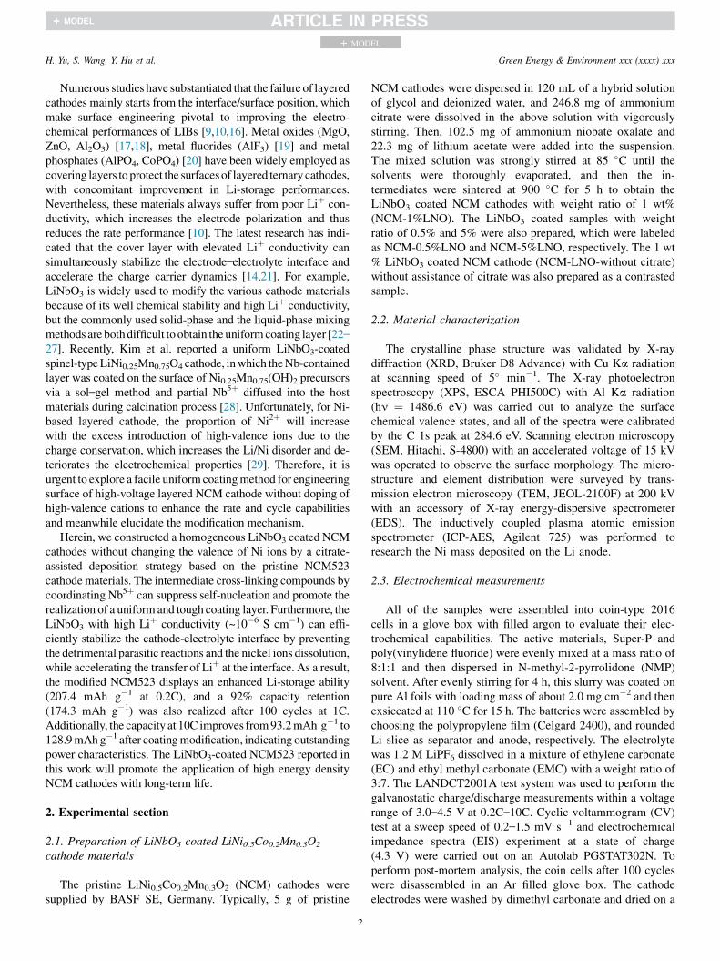
Numerous studies have substantiated that the failure of layeredcathodes mainly starts from the interface/surface position, whichmake surface engineering pivotal to improving the electro-chemical performances of LIBs [9,10,16]. Metal oxides (MgO,ZnO, Al2O3) [17,18], metal fluorides (AlF3) [19] and metalphosphates (AlPO4, CoPO4) [20] have been widely employed ascovering layers to protect the surfacesof layered ternary cathodes,with concomitant improvement in Li-storage performances.Nevertheless, these materials always suffer from poor Liþ con-ductivity, which increases the electrode polarization and thusreduces the rate performance [10]. The latest research has indi-cated that the cover layer with elevated Liþ conductivity cansimultaneously stabilize the electrode–electrolyte interface andaccelerate the charge carrier dynamics [14,21]. For example,LiNbO3 is widely used to modify the various cathode materialsbecause of its well chemical stability and high Liþ conductivity,but the commonly used solid-phase and the liquid-phase mixingmethods are bothdifficult to obtain the uniformcoating layer [22–
27]. Recently, Kim et al. reported a uniform LiNbO3-coatedspinel-typeLiNi0.25Mn0.75O4 cathode, inwhich theNb-containedlayer was coated on the surface of Ni0.25Mn0.75(OH)2 precursorsvia a sol–gel method and partial Nb5þ diffused into the hostmaterials during calcination process [28]. Unfortunately, for Ni-based layered cathode, the proportion of Ni2þ will increasewith the excess introduction of high-valence ions due to thecharge conservation, which increases the Li/Ni disorder and de-teriorates the electrochemical properties [29]. Therefore, it isurgent to explore a facile uniform coatingmethod for engineeringsurface of high-voltage layered NCM cathode without doping ofhigh-valence cations to enhance the rate and cycle capabilitiesand meanwhile elucidate the modification mechanism.
Herein, we constructed a homogeneous LiNbO3 coated NCMcathodes without changing the valence of Ni ions by a citrate-assisted deposition strategy based on the pristine NCM523cathodematerials. The intermediate cross-linking compounds bycoordinating Nb5þ can suppress self-nucleation and promote therealization of a uniform and tough coating layer. Furthermore, theLiNbO3 with high Liþ conductivity (~10�6 S cm�1) can effi-ciently stabilize the cathode-electrolyte interface by preventingthe detrimental parasitic reactions and the nickel ions dissolution,while accelerating the transfer of Liþ at the interface. As a result,the modified NCM523 displays an enhanced Li-storage ability(207.4 mAh g�1 at 0.2C), and a 92% capacity retention(174.3 mAh g�1) was also realized after 100 cycles at 1C.Additionally, the capacity at 10C improves from93.2mAh g�1 to128.9mAhg�1 after coatingmodification, indicating outstandingpower characteristics. The LiNbO3-coated NCM523 reported inthis work will promote the application of high energy densityNCM cathodes with long-term life.
2. Experimental section
2.1. Preparation of LiNbO3 coated LiNi0.5Co0.2Mn0.3O2
cathode materials
The pristine LiNi0.5Co0.2Mn0.3O2 (NCM) cathodes weresupplied by BASF SE, Germany. Typically, 5 g of pristine
2
NCM cathodes were dispersed in 120 mL of a hybrid solutionof glycol and deionized water, and 246.8 mg of ammoniumcitrate were dissolved in the above solution with vigorouslystirring. Then, 102.5 mg of ammonium niobate oxalate and22.3 mg of lithium acetate were added into the suspension.The mixed solution was strongly stirred at 85 �C until thesolvents were thoroughly evaporated, and then the in-termediates were sintered at 900 �C for 5 h to obtain theLiNbO3 coated NCM cathodes with weight ratio of 1 wt%(NCM-1%LNO). The LiNbO3 coated samples with weightratio of 0.5% and 5% were also prepared, which were labeledas NCM-0.5%LNO and NCM-5%LNO, respectively. The 1 wt% LiNbO3 coated NCM cathode (NCM-LNO-without citrate)without assistance of citrate was also prepared as a contrastedsample.
2.2. Material characterization
The crystalline phase structure was validated by X-raydiffraction (XRD, Bruker D8 Advance) with Cu Ka radiationat scanning speed of 5� min�1. The X-ray photoelectronspectroscopy (XPS, ESCA PHI500C) with Al Ka radiation(hn ¼ 1486.6 eV) was carried out to analyze the surfacechemical valence states, and all of the spectra were calibratedby the C 1s peak at 284.6 eV. Scanning electron microscopy(SEM, Hitachi, S-4800) with an accelerated voltage of 15 kVwas operated to observe the surface morphology. The micro-structure and element distribution were surveyed by trans-mission electron microscopy (TEM, JEOL-2100F) at 200 kVwith an accessory of X-ray energy-dispersive spectrometer(EDS). The inductively coupled plasma atomic emissionspectrometer (ICP-AES, Agilent 725) was performed toresearch the Ni mass deposited on the Li anode.
2.3. Electrochemical measurements
All of the samples were assembled into coin-type 2016cells in a glove box with filled argon to evaluate their elec-trochemical capabilities. The active materials, Super-P andpoly(vinylidene fluoride) were evenly mixed at a mass ratio of8:1:1 and then dispersed in N-methyl-2-pyrrolidone (NMP)solvent. After evenly stirring for 4 h, this slurry was coated onpure Al foils with loading mass of about 2.0 mg cm�2 and thenexsiccated at 110 �C for 15 h. The batteries were assembled bychoosing the polypropylene film (Celgard 2400), and roundedLi slice as separator and anode, respectively. The electrolytewas 1.2 M LiPF6 dissolved in a mixture of ethylene carbonate(EC) and ethyl methyl carbonate (EMC) with a weight ratio of3:7. The LANDCT2001A test system was used to perform thegalvanostatic charge/discharge measurements within a voltagerange of 3.0–4.5 V at 0.2C–10C. Cyclic voltammogram (CV)test at a sweep speed of 0.2–1.5 mV s�1 and electrochemicalimpedance spectra (EIS) experiment at a state of charge(4.3 V) were carried out on an Autolab PGSTAT302N. Toperform post-mortem analysis, the coin cells after 100 cycleswere disassembled in an Ar filled glove box. The cathodeelectrodes were washed by dimethyl carbonate and dried on a
H. Yu, S. Wang, Y. Hu et al. Green Energy & Environment xxx (xxxx) xxx
+ MODEL
heating plate of 60 �C. The Li anodes were dissolved in nitricacid and diluted by deionized water to a constant volume.
3. Results and discussion
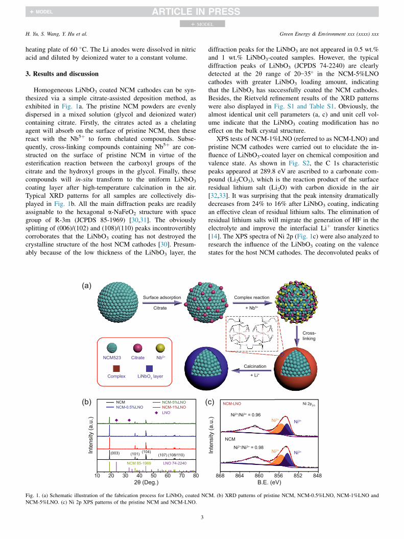
Homogeneous LiNbO3 coated NCM cathodes can be syn-thesized via a simple citrate-assisted deposition method, asexhibited in Fig. 1a. The pristine NCM powders are evenlydispersed in a mixed solution (glycol and deionized water)containing citrate. Firstly, the citrates acted as a chelatingagent will absorb on the surface of pristine NCM, then thesereact with the Nb5þ to form chelated compounds. Subse-quently, cross-linking compounds containing Nb5þ are con-structed on the surface of pristine NCM in virtue of theesterification reaction between the carboxyl groups of thecitrate and the hydroxyl groups in the glycol. Finally, thesecompounds will in-situ transform to the uniform LiNbO3
coating layer after high-temperature calcination in the air.Typical XRD patterns for all samples are collectively dis-played in Fig. 1b. All the main diffraction peaks are readilyassignable to the hexagonal a-NaFeO2 structure with spacegroup of R-3m (JCPDS 85-1969) [30,31]. The obviouslysplitting of (006)/(102) and (108)/(110) peaks incontrovertiblycorroborates that the LiNbO3 coating has not destroyed thecrystalline structure of the host NCM cathodes [30]. Presum-ably because of the low thickness of the LiNbO3 layer, the
Surface adsorption
Citrate
NCM523 Citrate Nb5+
Complex LiNbO3 layer
NCMNCM-0.5%LNO
NCM-5%LNONCM-1%LNOLNO
(003) (101) (104)(107) (108/110)
NCM 85-1969 LNO 74-2240
10 20 30 40 50 60 70 802θ (Deg.)
Inte
nsity
(a.u
.)
(a)
(b) (
Fig. 1. (a) Schematic illustration of the fabrication process for LiNbO3 coated NC
NCM-5%LNO. (c) Ni 2p XPS patterns of the pristine NCM and NCM-LNO.
3
diffraction peaks for the LiNbO3 are not appeared in 0.5 wt.%and 1 wt.% LiNbO3-coated samples. However, the typicaldiffraction peaks of LiNbO3 (JCPDS 74-2240) are clearlydetected at the 2q range of 20–35� in the NCM-5%LNOcathodes with greater LiNbO3 loading amount, indicatingthat the LiNbO3 has successfully coated the NCM cathodes.Besides, the Rietveld refinement results of the XRD patternswere also displayed in Fig. S1 and Table S1. Obviously, thealmost identical unit cell parameters (a, c) and unit cell vol-ume indicate that the LiNbO3 coating modification has noeffect on the bulk crystal structure.
XPS tests of NCM-1%LNO (referred to as NCM-LNO) andpristine NCM cathodes were carried out to elucidate the in-fluence of LiNbO3-coated layer on chemical composition andvalence state. As shown in Fig. S2, the C 1s characteristicpeaks appeared at 289.8 eV are ascribed to a carbonate com-pound (Li2CO3), which is the reaction product of the surfaceresidual lithium salt (Li2O) with carbon dioxide in the air[32,33]. It was surprising that the peak intensity dramaticallydecreases from 24% to 16% after LiNbO3 coating, indicatingan effective clean of residual lithium salts. The elimination ofresidual lithium salts will migrate the generation of HF in theelectrolyte and improve the interfacial Liþ transfer kinetics[14]. The XPS spectra of Ni 2p (Fig. 1c) were also analyzed toresearch the influence of the LiNbO3 coating on the valencestates for the host NCM cathodes. The deconvoluted peaks of
Complex reaction
+ Nb5+
Cross-linking
Calcination
+ Li+
NCM-LNO Ni 2p2/3
Ni2+/Ni3+ = 0.96Ni2+ Ni3+
NCM
Ni2+/Ni3+ = 0.98Ni2+ Ni3+
848852856860864868B.E. (eV)
O
OO
OO
OO
O
OO
O
O
ONb5+
OO O
O
O
O
O
OO
OO
O
ONb5+
OOO
O
c)
Inte
nsity
(a.u
.)
M. (b) XRD patterns of pristine NCM, NCM-0.5%LNO, NCM-1%LNO and
H. Yu, S. Wang, Y. Hu et al. Green Energy & Environment xxx (xxxx) xxx
+ MODEL
the Ni 2p3/2 spectra located at 855.9 and 854.6 eV suggest thecoexistence of Ni3þ and Ni2þ on the surface [33,34]. Theintensity ratios of Ni2þ/Ni3þ before and after coating modifi-cation are almost identical, indicating that the coating layerhas no effect on the valence states of the host materials. Onaccount of their similar ionic radius, the Ni2þ has a tendencyto form antisite defects in layered structure by exchanging sitewith Liþ, so the maintenance of valence states is beneficial topreserve the crystal structure. There is no visible skewing inthe XPS spectra of Co 2p and Mn 2p (Fig. S3), implying thattheir valence states are also not changed after coating modi-fication. Moreover, the resolved XPS peaks at 209.3 and206.6 eV (Fig. S4) forcefully demonstrates that niobium ionsoccur on the surface of the NCM-LNO cathodes [35].
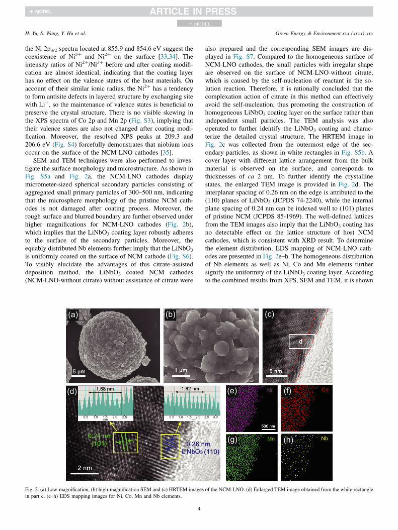
SEM and TEM techniques were also performed to inves-tigate the surface morphology and microstructure. As shown inFig. S5a and Fig. 2a, the NCM-LNO cathodes displaymicrometer-sized spherical secondary particles consisting ofaggregated small primary particles of 300–500 nm, indicatingthat the microsphere morphology of the pristine NCM cath-odes is not damaged after coating process. Moreover, therough surface and blurred boundary are further observed underhigher magnifications for NCM-LNO cathodes (Fig. 2b),which implies that the LiNbO3 coating layer robustly adheresto the surface of the secondary particles. Moreover, theequably distributed Nb elements further imply that the LiNbO3
is uniformly coated on the surface of NCM cathode (Fig. S6).To visibly elucidate the advantages of this citrate-assisteddeposition method, the LiNbO3 coated NCM cathodes(NCM-LNO-without citrate) without assistance of citrate were
0.5 1.0 2.52.01.5nm
0.5 1.0 2.01.5nm
(a) (b)
(d)
Fig. 2. (a) Low-magnification, (b) high-magnification SEM and (c) HRTEM images
in part c. (e–h) EDS mapping images for Ni, Co, Mn and Nb elements.
4
also prepared and the corresponding SEM images are dis-played in Fig. S7. Compared to the homogeneous surface ofNCM-LNO cathodes, the small particles with irregular shapeare observed on the surface of NCM-LNO-without citrate,which is caused by the self-nucleation of reactant in the so-lution reaction. Therefore, it is rationally concluded that thecomplexation action of citrate in this method can effectivelyavoid the self-nucleation, thus promoting the construction ofhomogeneous LiNbO3 coating layer on the surface rather thanindependent small particles. The TEM analysis was alsooperated to further identify the LiNbO3 coating and charac-terize the detailed crystal structure. The HRTEM image inFig. 2c was collected from the outermost edge of the sec-ondary particles, as shown in white rectangles in Fig. S5b. Acover layer with different lattice arrangement from the bulkmaterial is observed on the surface, and corresponds tothicknesses of ca 2 nm. To further identify the crystallinestates, the enlarged TEM image is provided in Fig. 2d. Theinterplanar spacing of 0.26 nm on the edge is attributed to the(110) planes of LiNbO3 (JCPDS 74-2240), while the internalplane spacing of 0.24 nm can be indexed well to (101) planesof pristine NCM (JCPDS 85-1969). The well-defined latticesfrom the TEM images also imply that the LiNbO3 coating hasno detectable effect on the lattice structure of host NCMcathodes, which is consistent with XRD result. To determinethe element distribution, EDS mapping of NCM-LNO cath-odes are presented in Fig. 2e–h. The homogeneous distributionof Nb elements as well as Ni, Co and Mn elements furthersignify the uniformity of the LiNbO3 coating layer. Accordingto the combined results from XPS, SEM and TEM, it is shown
2.5 3.0
Ni Co
Mn Nb
(c)
(e) (f)
(g) (h)
of the NCM-LNO. (d) Enlarged TEM image obtained from the white rectangle
H. Yu, S. Wang, Y. Hu et al. Green Energy & Environment xxx (xxxx) xxx
+ MODEL
that a uniform LiNbO3 layer has successfully realized on thesurface of secondary particles in NCM cathodes.
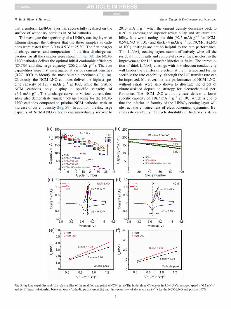
To investigate the superiority of a LiNbO3 coating layer forlithium storage, the batteries that use these samples as cath-odes were tested from 3.0 to 4.5 V at 25 �C. The first charge/discharge curves and comparation of the first discharge ca-pacities for all the samples were shown in Fig. S8. The NCM-LNO cathodes deliver the optimal initial coulombic efficiency(85.7%) and discharge capacity (206.2 mAh g�1). The ratecapabilities were first investigated at various current densities(0.2C–10C) to identfy the most suitable specimen (Fig. 3a).Obviously, the NCM-LNO cathodes deliver the highest spe-cific capacity of 128.9 mAh g�1 at 10C, while the pristineNCM cathodes only display a specific capacity of93.2 mAh g�1. The discharge curves at various current den-sities also demonstrate smaller voltage fading for the NCM-LNO cathodes compared to pristine NCM cathodes with anincrease of current density (Fig. S9). In addition, the dischargecapacity of NCM-LNO cathodes can immediately recover to
0.2C 0.5C 1C 2C 3C5C
10C
0.2C
NCM
NCM-1%LNONCM-0.5%LNO
NCM-5%LNONCM-LNO-without citrate
∆E = 0.17 V
NCM-LNO1st2nd3rd
∆E = 0.10 V
NCMNCM-LNO
Slope = 4.36
Slope = 3.16
Anodic peak
3.0-4.5 V
0
50
100
150
200
250
Cap
acity
(mAh
g-1)
0 6 12 18 24 30 36 42Cycle number
1.5
1.0
0.5
0
-0.5
-1.0
Cur
rent
(mA)
2.8 3.2 3.6 4.0 4.4 4.8Potential (V)
(a) (b
(d(c)
0
1.0
6.0
5.0
4.0
3.0
2.0
I P (m
A)
(f(e)
0.6 0.8 1.0 1.2V1/2 (mV S-1)1/2
Fig. 3. (a) Rate capability and (b) cycle stability of the modified and pristine NCM.
and (e, f) linear relationship between anodic/cathodic peak current (ip) and the sq
5
201.4 mA h g�1 when the current density decreases back to0.2C, suggesting the superior reversibility and structure sta-bility. It is worth noting that thin (92.5 mAh g�1 for NCM-0.5%LNO at 10C) and thick (4 mAh g�1 for NCM-5%LNOat 10C) coatings are not so helpful to the rate performance.Thin LiNbO3 coating layers cannot effectively wipe off theresidual lithium salts and completely cover the particles, so theimprovement for Liþ transfer kinetics is finite. The introduc-tion of thick LiNbO3 coatings with low electron conductivitywill hinder the transfer of electron at the interface and furthersacrifice the rate capability, although the Liþ transfer rate canbe improved. Moreover, the rate performance of NCM-LNO-without citrate were also shown to illustrate the effect ofcitrate-assisted deposition strategy for electrochemical per-formance. The NCM-LNO-without citrate deliver a lowerspecific capacity of 118.7 mA h g�1 at 10C, which is due tothat the inferior uniformity of the LiNbO3 coating layer willobstruct the enhancement of electrochemical dynamics. Be-sides rate capability, the cycle durability of batteries is also a
NCMNCM-LNONCM-LNO-without citrate
1C wihin 3.0-4.5V92%
83%
73%
1st2nd3rd ∆E = 0.23 V
NCM
∆E = 0.15 V
NCMNCM-LNO
Slope = 2.36
Slope = 1.93
Cathodic peak
0 20 40 60 80 100Cycle number
1.5
1.0
0.5
0
-0.5
-1.0
Cur
rent
(mA)
2.8 3.2 3.6 4.0 4.4 4.8Potential (V)
0
50
100
150
200
250
Cap
acity
(mAh
g-1)
)
)
0
1.0
4.0
3.0
2.0
I P (m
A)
)
0.6 0.8 1.0 1.2V1/2 (mV S-1)1/2
(c, d) The initial three CV curves in 3.0–4.5 V at a sweep speed of 0.2 mV s�1
uare root of the scan rate (n1/2) for the NCM-LNO and pristine NCM.
H. Yu, S. Wang, Y. Hu et al. Green Energy & Environment xxx (xxxx) xxx
+ MODEL
key parameter affecting their practical availability. As dis-played in Fig. 3b, a high reversible capacity (174.3 mA h g�1)is still maintained (capacity retention ratio of 92%) for NCM-LNO cathodes even after 100 cycles at 1C. In comparison, adramatic capacity fade is observed for the pristine NCMcathodes, which only retain 73% capacity after 100 cycles(from 174.6 mAh g�1 to 127.0 mAh g�1). Due to theincomplete and uneven coating layer, the capacity retentionratio of NCM-LNO-without citrate only improves to 83%. Thevariation trend of capacity and voltage platform during 100cycles were observed in homologous charge/discharge curves(Fig. S10). Clearly, the NCM-LNO cathodes show inappre-ciable voltage decline and less capacity loss, which matcheswell with the superior cycle stability. In contrast, the pristineNCM cathodes display dramatic capacity fading and moreapparent decay with voltage, implying the serious degradationof crystal structure and aggravating parasitic reaction at theinterface.
To explore the lithiation/delithiation performance, the firstthree cyclic voltammetry (CV) was performed at 0.2 mV s�1
over the voltage range of 3.0–4.5 V (Fig. 3c and d). All of thecurves display an analogous shape and a pair of oxidation/reduction peaks appeared at around 3.7 V are attributed to theNi2þ/Ni3þ redox, suggesting that the LiNbO3 coating does notin principle influence the charge/discharge. The parasitic re-action between the cathode and the electrolyte will form apassivation layer with low electron/Liþ kinetics at the inter-face and further increase the degree of polarization, which canbe evaluated by the potential separation (DE) between anodicand cathodic peaks in the CV curves [36,37]. It is clearlymeasured that the DE of NCM-LNO cathodes are 0.17 and0.10 V in the first two cycles, that are all lower than these ofpristine NCM cathodes (0.23 and 0.15 V). The smaller po-larization in NCM-LNO cathodes benefits from the effectivemitigation of interface parasitic reaction after coating modi-fication. Furthermore, the better coincidence of NCM-LNOcathodes in the subsequent secondary lithiation processfurther demonstrates a preferable reversibility during thelithiation-delithiation process. The CV tests at diverse sweeprates from 0.4 to 1.5 mV s�1 were further carried out toresearch the Liþ diffusion dynamics, as displayed in Fig. S11.The fine linear relationship between the peak current (ip) andthe square root of the scanning rate (v1/2) indicates the Liþ
transfer in NCM cathodes exhibits a diffusion-controlledprocess (Fig. 3e and f) [38,39], and that the diffusion co-efficients can be obtained according to the classical Randles–
Sevcik equation (the details of calculation is shown inSupporting Information). Impressively, the Liþ diffusion co-efficients of the NCM-LNO cathodes during the extraction/insertion process are 2.63 � 10�10 cm2 s�1 and7.70 � 10�11 cm2 s�1), which are all superior to the pristineNCM cathodes (1.38 � 10�10 cm2 s�1/5.15 � 10�11 cm2 s�1).The enhancement of Liþ transfer kinetics is attributed to theconstruction of a homogeneous LiNbO3 coating, which re-duces the generation of the electrochemical passivation layerby assuaging the surface parasitic reaction. Indeed, theLiNbO3 with high ionic conductivity (~10�6 S cm�1) can
6
further boost the Liþ transfer rate at the cathode-electrolyteinterface.
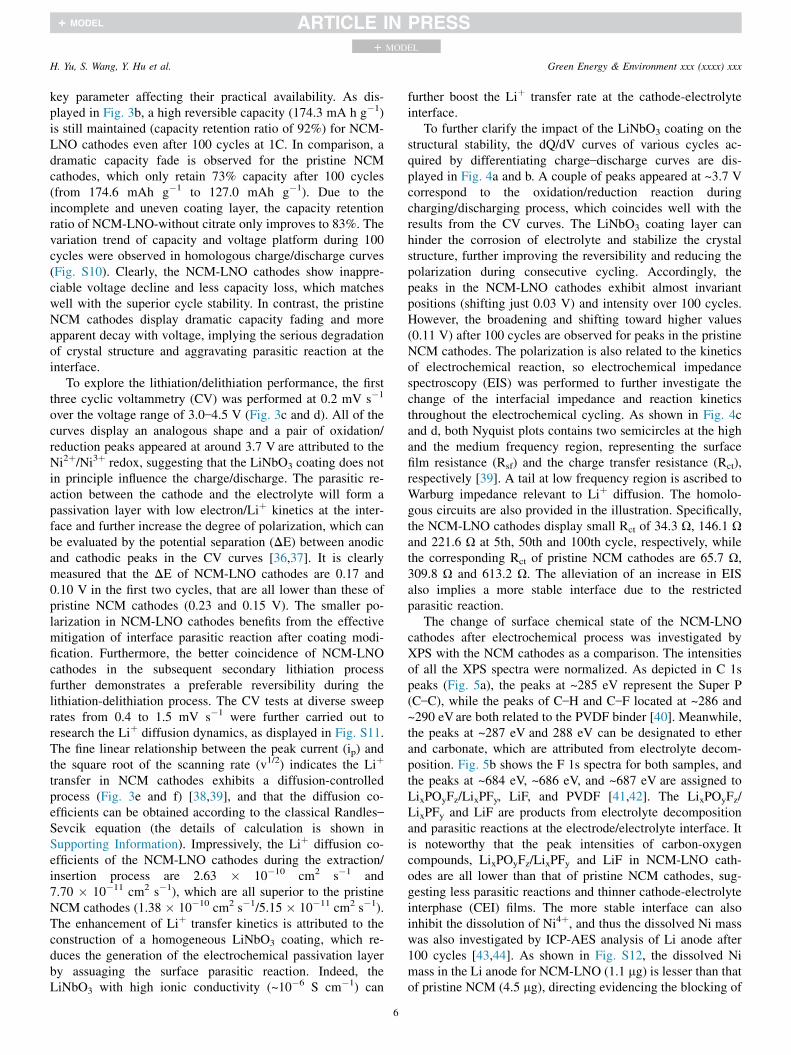
To further clarify the impact of the LiNbO3 coating on thestructural stability, the dQ/dV curves of various cycles ac-quired by differentiating charge–discharge curves are dis-played in Fig. 4a and b. A couple of peaks appeared at ~3.7 Vcorrespond to the oxidation/reduction reaction duringcharging/discharging process, which coincides well with theresults from the CV curves. The LiNbO3 coating layer canhinder the corrosion of electrolyte and stabilize the crystalstructure, further improving the reversibility and reducing thepolarization during consecutive cycling. Accordingly, thepeaks in the NCM-LNO cathodes exhibit almost invariantpositions (shifting just 0.03 V) and intensity over 100 cycles.However, the broadening and shifting toward higher values(0.11 V) after 100 cycles are observed for peaks in the pristineNCM cathodes. The polarization is also related to the kineticsof electrochemical reaction, so electrochemical impedancespectroscopy (EIS) was performed to further investigate thechange of the interfacial impedance and reaction kineticsthroughout the electrochemical cycling. As shown in Fig. 4cand d, both Nyquist plots contains two semicircles at the highand the medium frequency region, representing the surfacefilm resistance (Rsf) and the charge transfer resistance (Rct),respectively [39]. A tail at low frequency region is ascribed toWarburg impedance relevant to Liþ diffusion. The homolo-gous circuits are also provided in the illustration. Specifically,the NCM-LNO cathodes display small Rct of 34.3 U, 146.1 Uand 221.6 U at 5th, 50th and 100th cycle, respectively, whilethe corresponding Rct of pristine NCM cathodes are 65.7 U,309.8 U and 613.2 U. The alleviation of an increase in EISalso implies a more stable interface due to the restrictedparasitic reaction.
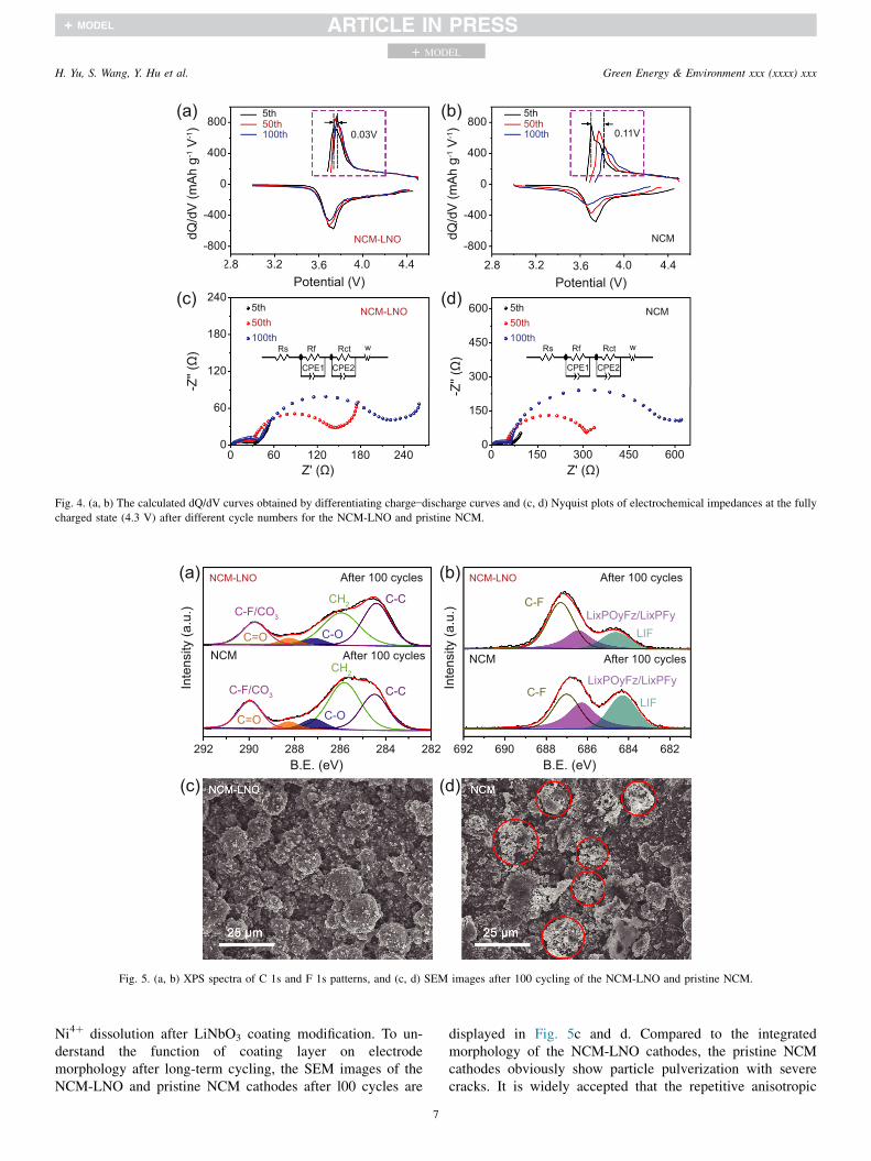
The change of surface chemical state of the NCM-LNOcathodes after electrochemical process was investigated byXPS with the NCM cathodes as a comparison. The intensitiesof all the XPS spectra were normalized. As depicted in C 1speaks (Fig. 5a), the peaks at ~285 eV represent the Super P(C–C), while the peaks of C–H and C–F located at ~286 and~290 eVare both related to the PVDF binder [40]. Meanwhile,the peaks at ~287 eV and 288 eV can be designated to etherand carbonate, which are attributed from electrolyte decom-position. Fig. 5b shows the F 1s spectra for both samples, andthe peaks at ~684 eV, ~686 eV, and ~687 eV are assigned toLixPOyFz/LixPFy, LiF, and PVDF [41,42]. The LixPOyFz/LixPFy and LiF are products from electrolyte decompositionand parasitic reactions at the electrode/electrolyte interface. Itis noteworthy that the peak intensities of carbon-oxygencompounds, LixPOyFz/LixPFy and LiF in NCM-LNO cath-odes are all lower than that of pristine NCM cathodes, sug-gesting less parasitic reactions and thinner cathode-electrolyteinterphase (CEI) films. The more stable interface can alsoinhibit the dissolution of Ni4þ, and thus the dissolved Ni masswas also investigated by ICP-AES analysis of Li anode after100 cycles [43,44]. As shown in Fig. S12, the dissolved Nimass in the Li anode for NCM-LNO (1.1 mg) is lesser than thatof pristine NCM (4.5 mg), directing evidencing the blocking of
NCM-LNO After 100 cycles
C-F/CO3
CH2 C-C
C-OC=O
NCM-LNO After 100 cycles
C-FLixPOyFz/LixPFy
LIF
NCM After 100 cycles
C-F/CO3
CH2
C-C
C-OC=O
After 100 cycles
C-FLixPOyFz/LixPFy
LIF
NCM
292 282284286288290B.E. (eV)
692 682684686688690B.E. (eV)
(a) (b)
Inte
nsity
(a.u
.)
Inte
nsity
(a.u
.)
(d)(c)
Fig. 5. (a, b) XPS spectra of C 1s and F 1s patterns, and (c, d) SEM images after 100 cycling of the NCM-LNO and pristine NCM.
5th50th100th 0.03V
NCM-LNO
5th50th100th 0.11V
NCM
2.8 3.2 3.6 4.0 4.4Potential (V)
2.8 3.2 3.6 4.0 4.4Potential (V)
800
400
0
-400
-800
dQ/d
V (m
Ah g
-1 V
-1) 800
400
0
-400
-800
dQ/d
V (m
Ah g
-1 V
-1)
NCM-LNO5th50th100th
5th50th100th
NCM
Rs Rf Rct w
CPE1 CPE2
0
60
120
180
240
0
150
300
450
600
-Z'' (
Ω)
-Z'' (
Ω)
Rs Rf Rct w
CPE1 CPE2
0 60 120 180 240 0 150 300 450 600Z' (Ω) Z' (Ω)
(a) (b)
(c) (d)
Fig. 4. (a, b) The calculated dQ/dV curves obtained by differentiating charge–discharge curves and (c, d) Nyquist plots of electrochemical impedances at the fully
charged state (4.3 V) after different cycle numbers for the NCM-LNO and pristine NCM.
H. Yu, S. Wang, Y. Hu et al. Green Energy & Environment xxx (xxxx) xxx
+ MODEL
Ni4þ dissolution after LiNbO3 coating modification. To un-derstand the function of coating layer on electrodemorphology after long-term cycling, the SEM images of theNCM-LNO and pristine NCM cathodes after l00 cycles are
7
displayed in Fig. 5c and d. Compared to the integratedmorphology of the NCM-LNO cathodes, the pristine NCMcathodes obviously show particle pulverization with severecracks. It is widely accepted that the repetitive anisotropic
H. Yu, S. Wang, Y. Hu et al. Green Energy & Environment xxx (xxxx) xxx
+ MODEL
volume change of the primary particles during the delithiation/lithiation process will cause the intergranular crack, which canserve as fresh reaction sites to generate more destructiveparasitic reactions with the electrolyte. The cumulative detri-mental reactions will drastically undermine the surface struc-ture and morphology of the pristine NCM cathode [36].Therefore, the integrated morphology of the NCM-LNOcathodes proves that the LiNbO3 coating layer significantlyreduces the penetration of the electrolyte and parasitic re-actions at the interface, further stabilizing the morphology andslowing the reduction in capacity. Additionally, the particlepulverization can also destroy the electron/Liþ transfer insidethe active materials to reduce the rate capability, so the com-plete morphology can also improve the rate performance. Inconclusion, the tough and uniform LiNbO3 coating layer isadvantageous for enhancing surface and consequently bulkstructural stability and acts a critical role in high energy-powerdensity NCM cathodes with enhanced life.
4. Conclusions
In summary, we developed a citrate-assisted depositionconcept to achieve a homogeneous LiNbO3 coating layer on aNCM523 surface that avoided self-nucleation and showedlithium conductivity. The LiNbO3 coating layer acted as aphysical barrier can suppress electrolyte attack and thedissolution of metal ions, hence stabilizing the electrode–
electrolyte interface. Moreover, the high Liþ conductivity ofLiNbO3 can also significantly improve the Liþ diffusion ki-netics and reduce electrode polarization during charging–
discharging processes. As anticipated, the NCM-LNO cath-odes exhibit outstanding Li-storage behavior including highcapacity, enhanced rate capability and better cycling stabilitywithin the range 3.0–4.5 V. Specifically, the as-obtained NCM-LNO cathodes exhibit a specific capacity of 207.4 mAh g�1 at0.2C and 128.9 mAh g�1 at 10C. Meanwhile, a 92% retentionin capacity was realized after 100 cycles at 1C with smallerdecline of voltage platform. The decreased side reaction andwell-preserved morphology after 100 cycles further confirmthe superior surface chemical stability and structure integrityof NCM-LNO cathodes. The surface engineering strategyproposed in this paper can also extended to various cathodematerials that suffer from performance degradation propa-gating from the surface.
Conflict of interest
There are no conflicts of interest.
Acknowledgments
This work was supported by the National Natural ScienceFoundation of China (21975074, 91534202, and 91834301),the Shanghai Scientific and Technological Innovation Project(18JC1410500), and the Fundamental Research Funds for theCentral Universities (222201718002).
8
Appendix A. Supplementary data
Supplementary data to this article can be found online athttps://doi.org/10.1016/j.gee.2020.09.011.
References
[1] J.M. Tarascon, M. Armand, Nature 414 (2011) 359–367.
[2] R. Weber, M. Genovese, A. Louli, S. Hames, C. Martin, I. Hill, J. Dahn,
Nat. Energy 4 (2019) 683–689.
[3] H. Zhao, B. Qiu, H.C. Guo, K. Jia, Z.P. Liu, Y.G. Xia, Green Energy
Environ. 2 (2017) 174–185.
[4] W. Li, E. Erickson, A. Manthiram, Nat. Energy 5 (2020) 26–34.
[5] J. Kim, H. Lee, H. Cha, M. Yoon, M. Park, J. Cho, Adv. Energy Mater. 8
(2018) 1702028.
[6] J.A. Gilbert, J. Bareno, D.P. Abraham, J. Electrochem. Soc. 164 (2017)
A6054–A6065.
[7] W. Li, B. Song, A. Manthiram, Chem. Soc. Rev. 46 (2017) 3006–3059.
[8] J. Shi, D. Xiao, M. Ge, X. Yu, Y. Chu, X. Huang, X. Zhang, Y. Yin,
X. Yang, Y. Guo, L. Gu, L. Wan, Adv. Mater. 9 (2018) 1705575.
[9] S. Jung, H. Gwon, J. Hong, K. Park, D. Seo, H. Kim, J. Hyun, W. Yang,
K. Kang, Adv. Energy Mater. 4 (2014) 1300787.
[10] Y. Ruan, X. Song, Y. Fu, C. Song, V. Battaglia, J. Power Sources 400
(2018) 539–548.
[11] H. Kim, M.G. Kim, H.Y. Jeong, H. Nam, J. Cho, Nano Lett. 15 (2015)
2111–2119.
[12] S. Li, X. Fu, J. Zhou, Y. Han, P. Qi, G. Xing, F. Xiao, W. Bo, J. Mater.
Chem. 4 (2016) 5823–5827.
[13] H. Kim, S. Lee, H. Cho, J. Kim, J. Lee, S. Park, S. Joo, S. Kim, Y. Cho,
H. Song, S. Kwak, J. Cho, Adv. Mater. 28 (2016) 4705–4712.
[14] H.F. Yu, Y.G. Li, Y.J. Hu, H. Jiang, C.Z. Li, Ind. Eng. Chem. Res. 58
(2019) 4108–4115.
[15] H.W. Zhu, H.F. Yu, H. Jiang, Y.J. Hu, H.B. Jiang, C.Z. Li, Chem. Eng.
Sci. 217 (2020) 115518.
[16] H. Jiang, Y.S. Han, Q. Zhang, J.X. Wang, Y. Fan, C.Z. Li, Rev. Chem.
Eng. 35 (2019) 917–927.
[17] Y. Su, S. Cui, Z. Zhuo, W. Yang, X. Wang, F. Pan, ACS Appl. Mater.
Interfaces 7 (2015), 25205-25112.
[18] Y. Cho, Y. Lee, S. Park, Y. Lee, J. Cho, Electrochim. Acta 1 (2010) 333–
339.
[19] S. Lee, C. Yoon, K. Amine, Y. Sun, J. Power Sources 234 (2013) 201–207.
[20] R. Qi, J. Shi, X. Zhang, X. Zeng, Y. Yin, J. Xu, L. Chen, W. Fu, Y. Guo,
L. Wan, Sci. China Chem. 60 (2017) 1230–1235.
[21] H.G. Song, J.Y. Kim, K.T. Kim, Y.J. Park, J. Power Sources 196 (2011)
6847–6855.
[22] N. Ohta, K. Takada, I. Sakaguchi, L.Q. Zhang, R.Z. Ma, K. Fukuda,
M. Osada, T. Sasaki, Electrochem. Commun. 9 (2007) 1486–1490.
[23] W. Sun,M.Xie,X.X. Shi, L.Q. Zhang,Mater. Res. Bull. 61 (2015) 287–291.
[24] Z.J. Zhang, S.L. Chou, Q.F. Gu, H.K. Liu, H.J. Li, K. Ozawa, J.Z. Wang,
ACS Appl. Mater. Interfaces 6 (2014) 22155–22165.
[25] M. Gellert, K.I. Gries, J. Sann, E. Pfeifer, K. Volz, B. Roling, Solid State
Ionics 287 (2016) 8–12.
[26] X.L. Li, L.B. Jin, D.W. Song, H.Z. Zhang, X.X. Shi, Z.Y. Wang,
L.Q. Zhang, L.Y. Zhu, J. Energy Chem. 40 (2020) 39–45.
[27] Y.J. Kim, R. Rajagopal, S. Kang, K.S. Ryu, Chem. Eng. J. 386 (2020)
123975.
[28] H. Kim, D. Byun, W. Chang, H.G. Jung, W.C. Choi, J. Mater. Chem. 5
(2017) 25077–25089.
[29] G.Z. Shang, Y.W. Tang, Y.Q. Lai, J. Wu, X. Yang, H.X. Li, C. Peng,
J.F. Zheng, Z.A. Zhang, J. Power Sources 423 (2019) 246–254.
[30] S. Kang, J. Kim, M. Stoll, D. Abraham, Y. Sun, K. Amine, J. Power
Sources 112 (2002) 41–48.
[31] R. Zheng, W. Wang, Y. Dai, Q. Ma, Y. Liu, D. Mu, R. Li, J. Ren, C. Dai,
Green Energy Environ. 2 (2017) 42–50.
[32] Y. Chen, S. Tang, S. Deng, T. Lei, Y. Li, W. Li, G. Cao, J. Zhu, J. Zhang,
J. Power Sources 431 (2019) 8–16.

H. Yu, S. Wang, Y. Hu et al. Green Energy & Environment xxx (xxxx) xxx
+ MODEL
[33] X. Zheng, X. Li, Z. Wang, H. Guo, Z. Huang, G. Yan, D. Wang, Elec-
trochim. Acta 191 (2016) 832–840.
[34] H. Liu, Y. Yang, J. Zhang, J. Power Sources 162 (2006) 644–650.
[35] S. Liu, X. Chen, J. Zhao, J. Su, C. Zhang, T. Huang, J. Wu, A. Yua,
J. Power Sources 374 (2018) 149–157.
[36] Y. Wu, H. Ming, M. Li, J. Zhang, W. Wahyudi, L. Xie, X. He, J. Wang,
Y. Wu, J. Ming, ACS Energy Lett. 4 (2019) 656–665.
[37] Q.Q. Jiang, H.F. Yu, Y.J. Hu, H. Jiang, C.Z. Li, Ind. Eng. Chem. Res. 58
(2019) 23099–23105.
[38] L. Chen, H. Jiang, Y. Hu, H.Wang, C. Li, Sci. ChinaMater. 61 (2018) 1049–
1056.
9
[39] Y. Li, H. Yu, Y. Hu, H. Jiang, C. Li, J. Energy Chem. 2 (2018) 559–564.
[40] Y. Li, S. Wan, G.M. Veith, R.R. Unocic, M.P. Paranthaman, S. Dai,
X.G. Sun, Adv. Energy Mater. 7 (2017) 1601397.
[41] M. Xu, L. Zhou, Y. Dong, Y. Chen, J. Demeaux, A.D. MacIntosh,
A. Garsuch, B.L. Lucht, Energy Environ. Sci. 9 (2016) 1308–1319.
[42] Y. Che, X. Lin L. Xing, X. Guan, R. Guo, G. Lan, Q. Zheng, W. Zhang,
W. Li, J. Energy Chem. 52 (2021) 361–371.
[43] J.Y. Li, W.D. Li, Y. You, A. Manthiram, Adv. Energy Mater. 8 (2018)
1801957.
[44] W. Liu, J. Li, W. Li, H.Y. Xu, C. Zhang, X.P. Qiu, Nat. Commun. 11
(2020) 3629.