Embed Size (px)
Citation preview

OWNER’S MANUAL
3B3-F8199-11
XF50XLIT-11626-21-55
3B3-F8199-11_Cv.pmd 2007/07/30, 16:382

1
2
3
4
5
6
7
8
9
EAU10041
3B3-F8199-11_ch0.pmd 2007/07/30, 16:331

1
2
3
4
5
6
7
8
9
EAU10050
INTRODUCTIONEAU10090
Congratulations on your purchase of the Yamaha XF50X. This model is the result of Yamaha’s vast experience in theproduction of fine sporting, touring, and pacesetting racing machines. It represents the high degree of craftsmanship andreliability that have made Yamaha a leader in these fields.
This manual will give you an understanding of the operation, inspection, and basic maintenance of this scooter. If you haveany questions concerning the operation or maintenance of your scooter, please consult a Yamaha dealer.
The design and manufacture of this Yamaha scooter fully comply with the emissions standards for clean air applicable at thedate of manufacture. Yamaha has met these standards without reducing the performance or economy of operation of thescooter. To maintain these high standards, it is important that you and your Yamaha dealer pay close attention to therecommended maintenance schedules and operating instructions contained within this manual.
3B3-F8199-11_ch0.pmd 2007/07/30, 16:332
1
2
3
4
5
6
7
8
9
EAU10122
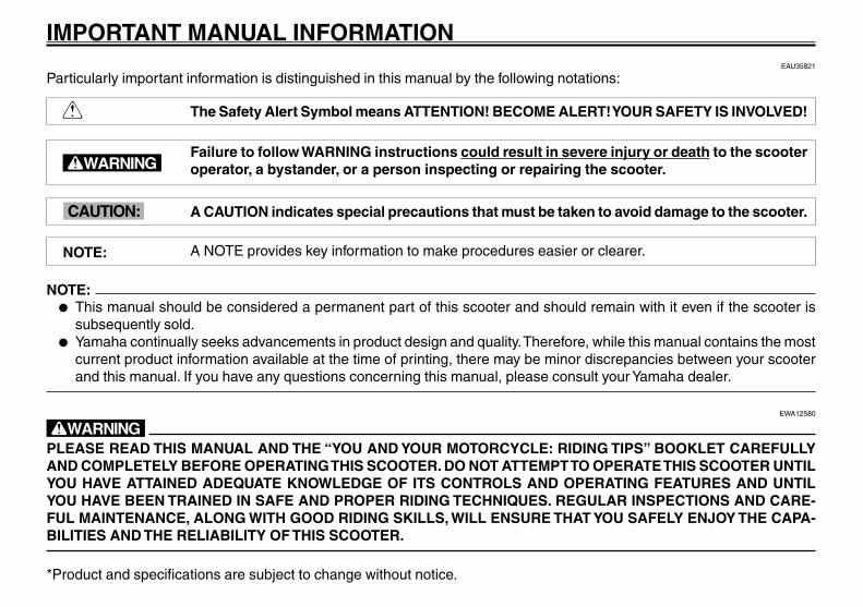
IMPORTANT MANUAL INFORMATIONEAU35821
Particularly important information is distinguished in this manual by the following notations:
The Safety Alert Symbol means ATTENTION! BECOME ALERT! YOUR SAFETY IS INVOLVED!
Failure to follow WARNING instructions could result in severe injury or death to the scooteroperator, a bystander, or a person inspecting or repairing the scooter.
A CAUTION indicates special precautions that must be taken to avoid damage to the scooter.
A NOTE provides key information to make procedures easier or clearer.
NOTE:● This manual should be considered a permanent part of this scooter and should remain with it even if the scooter is
subsequently sold.● Yamaha continually seeks advancements in product design and quality. Therefore, while this manual contains the most
current product information available at the time of printing, there may be minor discrepancies between your scooterand this manual. If you have any questions concerning this manual, please consult your Yamaha dealer.
EWA12580
wPLEASE READ THIS MANUAL AND THE “YOU AND YOUR MOTORCYCLE: RIDING TIPS” BOOKLET CAREFULLYAND COMPLETELY BEFORE OPERATING THIS SCOOTER. DO NOT ATTEMPT TO OPERATE THIS SCOOTER UNTILYOU HAVE ATTAINED ADEQUATE KNOWLEDGE OF ITS CONTROLS AND OPERATING FEATURES AND UNTILYOU HAVE BEEN TRAINED IN SAFE AND PROPER RIDING TECHNIQUES. REGULAR INSPECTIONS AND CARE-FUL MAINTENANCE, ALONG WITH GOOD RIDING SKILLS, WILL ENSURE THAT YOU SAFELY ENJOY THE CAPA-BILITIES AND THE RELIABILITY OF THIS SCOOTER.
*Product and specifications are subject to change without notice.
w
cC
NOTE:
Q
3B3-F8199-11_ch0.pmd 2007/07/30, 16:333
1
2
3
4
5
6
7
8
9
EAU10122
IMPORTANT MANUAL INFORMATION
EAUT2190
XF50XOWNER’S MANUAL
©2007 by Yamaha Motor Corporation, U.S.A.1st edition, September 2007
All rights reserved.Any reprinting or unauthorized usewithout the written permission ofYamaha Motor Corporation, U.S.A.
is expressly prohibited.Printed in Taiwan.
P/N LIT-11626-21-55
AFFIX DEALER
LABEL HERE
3B3-F8199-11_ch0.pmd 2007/07/30, 16:334

1
2
3
4
5
6
7
8
9
EAU10210
TABLE OF CONTENTSSAFETY INFORMATION ................... 1-1
Further safe-riding points ............... 1-4Location of important labels ........... 1-5
DESCRIPTION................................... 2-1Left view ......................................... 2-1Right view ....................................... 2-2Controls and instruments ............... 2-3
INSTRUMENT AND CONTROL FUNC-TIONS ................................................ 3-1
Main switch/steering lock ............... 3-1Keyhole cover ................................. 3-2Indicator and warning lights ........... 3-2Speedometer unit ........................... 3-3Fuel gauge ...................................... 3-3Handlebar switches ........................ 3-4Front brake lever ............................. 3-5Rear brake lever ............................. 3-5Fuel tank cap .................................. 3-5Fuel ................................................. 3-6Catalytic converters ........................ 3-7Kickstarter ....................................... 3-7Seat ................................................ 3-8Luggage hook ................................. 3-8Helmet holder ................................. 3-8Storage compartment ..................... 3-9
PRE-OPERATION CHECKS ............. 4-1Pre-operation check list .................. 4-2
OPERATION AND IMPORTANT RIDINGPOINTS .............................................. 5-1
Starting a cold engine .................... 5-1Starting off ...................................... 5-2Acceleration and deceleration ........ 5-2Braking ........................................... 5-2Engine break-in .............................. 5-3Parking ........................................... 5-3
PERIODIC MAINTENANCE AND MINORREPAIR .............................................. 6-1
PERIODIC MAINTENANCE ........... 6-1Periodic maintenance chart for the
emission control system .............. 6-2General maintenance and lubrication
chart ............................................ 6-3Removing and installing panels ..... 6-6Checking the spark plug ................. 6-7Engine oil and oil strainer ............... 6-8Final transmission oil .................... 6-10Coolant ......................................... 6-11Replacing the air filter element ..... 6-13Checking the throttle cable free
play ............................................ 6-13Valve clearance ............................ 6-13Tires .............................................. 6-14Cast wheels .................................. 6-15Adjusting the brake lever free play 6-15Adjusting the rear brake lever free
play ............................................ 6-16
Checking the front and rear brakeshoes ......................................... 6-17
Checking and lubricating the throttlegrip and cable ............................ 6-17
Lubricating the front and rear brakelevers ......................................... 6-18
Checking and lubricating thecenterstand ............................... 6-18
Checking the front fork ................. 6-18Checking the steering ................... 6-19Checking the wheel bearings ....... 6-20Battery .......................................... 6-20Replacing the fuse ........................ 6-21Replacing the headlight bulb ........ 6-22Replacing the tail/brake light bulb 6-23Replacing a turn signal light bulb .6-24Troubleshooting ............................ 6-25Troubleshooting charts ................. 6-26
SCOOTER CARE AND STORAGE ... 7-1Care ................................................ 7-1Storage ........................................... 7-3
SPECIFICATIONS ............................. 8-1
CONSUMER INFORMATION ............ 9-1Identification numbers .................... 9-1Reporting safety defects ................. 9-3Motorcycle noise regulation ............ 9-4Maintenance record ........................ 9-5
3B3-F8199-11_ch0.pmd 2007/08/01, 10:575
1
2
3
4
5
6
7
8
9
EAU10210
TABLE OF CONTENTSYAMAHA MOTOR CORPORATION,
U.S.A. RIVA LIMITEDWARRANTY ................................ 9-7
YAMAHA EXTENDED SERVICE(Y.E.S.) ........................................ 9-9
3B3-F8199-11_ch0.pmd 2007/07/30, 16:336

1-1
1
2
3
4
5
6
7
8
9
QQQQQ SAFETY INFORMATIONEAU10220
QQQQQ SAFETY INFORMATIONSafety information<IXE>
EAU10240
SCOOTERS ARE SINGLE TRACKVEHICLES. THEIR SAFE USE ANDOPERATION ARE DEPENDENTUPON THE USE OF PROPER RIDINGTECHNIQUES AS WELL AS THE EX-PERTISE OF THE OPERATOR. EV-ERY OPERATOR SHOULD KNOWTHE FOLLOWING REQUIREMENTSBEFORE RIDING THIS SCOOTER.HE OR SHE SHOULD:
● OBTAIN THOROUGH INSTRUC-TIONS FROM A COMPETENTSOURCE ON ALL ASPECTS OFSCOOTER OPERATION.
● OBSERVE THE WARNINGS ANDMAINTENANCE REQUIRE-MENTS IN THE OWNER’SMANUAL.
● OBTAIN QUALIFIED TRAINING INSAFE AND PROPER RIDINGTECHNIQUES.
● OBTAIN PROFESSIONAL TECH-NICAL SERVICE AS INDICATEDBY THE OWNER’S MANUALAND/OR WHEN MADE NECES-SARY BY MECHANICAL CONDI-TIONS.
Safe riding● Always make pre-operation
checks. Careful checks may helpprevent an accident.
● This scooter is designed to carrythe operator only. No passengers.
● The failure of motorists to detectand recognize scooters in traffic isthe predominating cause of auto-mobile/scooter accidents. Manyaccidents have been caused by anautomobile driver who did not seethe scooter. Making yourself con-spicuous appears to be very effec-tive in reducing the chance of thistype of accident.
Therefore:• Wear a brightly colored jacket.• Use extra caution when
approaching and passingthrough intersections, sinceintersections are the most likelyplaces for scooter accidents tooccur.
• Ride where other motorists cansee you. Avoid riding in anothermotorist’s blind spot.
● Many accidents involve inexperi-enced operators. In fact, many op-erators who have been involved inaccidents do not even have a cur-rent driver’s license.• Make sure that you are quali-
fied and that you only lend yourscooter to other qualifiedoperators.
• Know your skills and limits.Staying within your limits mayhelp you to avoid an accident.
• We recommend that youpractice riding your scooterwhere there is no traffic untilyou have become thoroughlyfamiliar with the scooter and allof its controls.
● Many accidents have been causedby error of the scooter operator. Atypical error made by the operatoris veering wide on a turn due toEXCESSIVE SPEED orundercornering (insufficient leanangle for the speed).• Always obey the speed limit
and never travel faster thanwarranted by road and trafficconditions.
3B3-F8199-11_ch1.pmd 2007/07/30, 16:341

1-2
1
2
3
4
5
6
7
8
9
QQQQQ SAFETY INFORMATION• Always signal before turning or
changing lanes. Make sure thatother motorists can see you.
● The posture of the operator is im-portant for proper control. The op-erator should keep both hands onthe handlebar and both feet on thefootboard during operation to main-tain control of the scooter.
● Never ride under the influence ofalcohol or other drugs.
● This scooter is designed for on-road use only. It is not suitable foroff-road use.
Protective apparelThe majority of fatalities from scooteraccidents are the result of head inju-ries. The use of a safety helmet is thesingle most critical factor in the preven-tion or reduction of head injuries.
● Always wear an approved helmet.● Wear a face shield or goggles. Wind
in your unprotected eyes couldcontribute to an impairment of vi-sion that could delay seeing a haz-ard.
● The use of a jacket, substantial
shoes, trousers, gloves, etc., is ef-fective in preventing or reducingabrasions or lacerations.
● Never wear loose-fitting clothes,otherwise they could catch on thecontrol levers or wheels and causeinjury or an accident.
● Never touch the engine or exhaustsystem during or after operation.They become very hot and cancause burns. Always wear protec-tive clothing that covers your legs,ankles, and feet.
ModificationsModifications made to this scooter notapproved by Yamaha, or the removal oforiginal equipment, may render thescooter unsafe for use and may causesevere personal injury. Modificationsmay also make your scooter illegal touse.
Loading and accessoriesAdding accessories or cargo to yourscooter can adversely affect stabilityand handling if the weight distributionof the scooter is changed. To avoid the
possibility of an accident, use extremecaution when adding cargo or acces-sories to your scooter. Use extra carewhen riding a scooter that has addedcargo or accessories. Here are somegeneral guidelines to follow if loadingcargo or adding accessories to yourscooter:
LoadingThe total weight of the operator, acces-sories and cargo must not exceed themaximum load limit of 85 kg (187 lb).When loading within this weight limit,keep the following in mind:
● Cargo and accessory weightshould be kept as low and close tothe scooter as possible. Make sureto distribute the weight as evenlyas possible on both sides of thescooter to minimize imbalance orinstability.
● Shifting weights can create a sud-den imbalance. Make sure that ac-cessories and cargo are securelyattached to the scooter beforeriding. Check accessory mountsand cargo restraints frequently.
3B3-F8199-11_ch1.pmd 2007/07/30, 16:342

1-3
1
2
3
4
5
6
7
8
9
QQQQQ SAFETY INFORMATION● Never attach any large or heavy
items to the handlebar, front fork,or front fender. Such items can cre-ate unstable handling or a slowsteering response.
AccessoriesGenuine Yamaha accessories havebeen specifically designed for use onthis scooter. Since Yamaha cannot testall other accessories that may be avail-able, you must personally be respon-sible for the proper selection, installa-tion and use of non-Yamaha accesso-ries. Use extreme caution when select-ing and installing any accessories.Keep the following guidelines in mind,as well as those provided under “Load-ing” when mounting accessories.
● Never install accessories or carrycargo that would impair the perfor-mance of your scooter. Carefullyinspect the accessory before us-ing it to make sure that it does notin any way reduce ground clear-ance or cornering clearance, limitsuspension travel, steering travelor control operation, or obscure
lights or reflectors.• Accessories fitted to the
handlebar or the front fork areacan create instability due toimproper weight distribution oraerodynamic changes. Ifaccessories are added to thehandlebar or front fork area,they must be as lightweight aspossible and should be kept toa minimum.
• Bulky or large accessories mayseriously affect the stability ofthe scooter due to aerody-namic effects. Wind mayattempt to lift the scooter, orthe scooter may becomeunstable in cross winds. Theseaccessories may also causeinstability when passing orbeing passed by large vehicles.
• Certain accessories candisplace the operator from hisor her normal riding position.This improper position limitsthe freedom of movement ofthe operator and may limitcontrol ability, therefore, such
accessories are not recom-mended.
● Use caution when adding electri-cal accessories. If electrical acces-sories exceed the capacity of thescooter’s electrical system an elec-tric failure could result, which couldcause a dangerous loss of lightsor engine power.
Gasoline and exhaust gas● GASOLINE IS HIGHLY FLAM-
MABLE:• Always turn the engine off
when refueling.• Take care not to spill any
gasoline on the engine orexhaust system when refuel-ing.
• Never refuel while smoking orin the vicinity of an open flame.
● Never start the engine or let it runfor any length of time in a closedarea. The exhaust fumes are poi-sonous and may cause loss of con-sciousness and death within ashort time. Always operate yourscooter in an area that has ad-
3B3-F8199-11_ch1.pmd 2007/07/30, 16:343

1-4
1
2
3
4
5
6
7
8
9
QQQQQ SAFETY INFORMATIONSafe-riding points<IXE>
equate ventilation.● Always turn the engine off before
leaving the scooter unattended andremove the key from the mainswitch. When parking the scooter,note the following:• The engine and exhaust
system may be hot, therefore,park the scooter in a placewhere pedestrians or childrenare not likely to touch these hotareas.
• Do not park the scooter on aslope or soft ground, otherwiseit may fall over.
• Do not park the scooter near aflammable source (e.g., akerosene heater, or near anopen flame), otherwise it couldcatch fire.
● If you should swallow any gasoline,inhale a lot of gasoline vapor, orallow gasoline to get in your eyes,see your doctor immediately. If anygasoline spills on your skin or cloth-ing, immediately wash the affectedarea with soap and water andchange your clothes.
EAUT2030
Further safe-riding points● Make sure to signal clearly when
making turns.● Braking can be extremely difficult
on a wet road. Avoid hard braking,because the scooter could slide.Apply the brakes slowly when stop-ping on a wet surface.
● Slow down as you approach a cor-ner or turn. Once you have com-pleted a turn, accelerate slowly.
● Be careful when passing parkedcars. A driver might not see you andopen a door in your path.
● Railroad crossings, streetcar rails,iron plates on road constructionsites, and manhole covers becomeextremely slippery when wet. Slowdown and cross them with caution.Keep the scooter upright, otherwiseit could slide out from under you.
● The brake lining could get wetwhen you wash the scooter. Afterwashing the scooter, check thebrakes before riding.
● Always wear a helmet, gloves, trou-sers (tapered around the cuff andankle so they do not flap), and a
bright colored jacket.● Do not carry too much luggage on
the scooter. An overloaded scooteris unstable.
3B3-F8199-11_ch1.pmd 2007/07/30, 16:344

1-5
1
2
3
4
5
6
7
8
9
QQQQQ SAFETY INFORMATIONEAU10381
Location of important labelsPlease read the following important labels carefully before operating this vehicle.
Labels, location of<IXE>
1 2,3 4
3B3-F8199-11_ch1.pmd 2007/07/30, 16:345

1-6
1
2
3
4
5
6
7
8
9
QQQQQ SAFETY INFORMATION
1
2
3
4
3B3-F8199-11_ch1.pmd 2007/07/30, 16:346

2-1
1
2
3
4
5
6
7
8
9
DESCRIPTIONEAU10400
DESCRIPTIONPart locations<IXE>
EAU10410
Left view
1. Front turn signal light (page 6-24)2. Fuel tank cap (page 3-5)3. Luggage hook (page 3-8)4. Helmet holder (page 3-8)5. Battery (page 6-20)6. Storage compartment (page 3-9)7. Air filter (page 6-13)8. Rear turn signal light (page 6-24)
1 2 3, 4, 5 6 87
3B3-F8199-11_ch2.pmd 2007/07/30, 16:341

2-2
1
2
3
4
5
6
7
8
9
DESCRIPTIONEAU10420
Right view
1. Tail/brake light (page 6-23)2. Seat (page 3-8)3. Coolant reservoir (page 6-11)4. Headlight (page 6-22)5. Spark plug (page 6-7)6. Centerstand (page 6-18)7. Muffler (page 3-7)
2 31 4
567
3B3-F8199-11_ch2.pmd 2007/07/30, 16:342

2-3
1
2
3
4
5
6
7
8
9
DESCRIPTIONEAU10430
Controls and instruments
1. Rear brake lever (page 3-5)2. Left handlebar switches (page 3-4)3. Speedometer unit (page 3-3)4. Fuel gauge (page 3-3)5. Right handlebar switches (page 3-4)6. Front brake lever (page 3-5)7. Throttle grip (page 6-17)8. Main switch/steering lock (page 3-1)
1 2 3 4 5 6 7
8
3B3-F8199-11_ch2.pmd 2007/07/30, 16:343

3-1
1
2
3
4
5
6
7
8
9
INSTRUMENT AND CONTROL FUNCTIONSEAU1044D
INSTRUMENT AND CONTROL FUNCTIONSEAU10460
Main switch/steering lock
ZAUM00**
The main switch/steering lock controlsthe ignition and lighting systems, and isused to lock the steering. The variouspositions are described below.
Main switch/steering lock<IXE>
EAUT2060
ONAll electrical circuits are supplied withpower, and the meter lighting, taillight,and license plate light come on, and theengine can be started. The key cannotbe removed.
NOTE:The headlight comes on automaticallywhen the engine is started and stayson until the key is turned to “OFF”, evenif the engine stalls.
EAU10660
OFFAll electrical systems are off. The keycan be removed.
EAU10680
LOCKThe steering is locked, and all electri-cal systems are off. The key can be re-moved.
To lock the steering
ZAUM00**
1
1. Push.
1. Turn the handlebars all the way tothe left.
2. Push the key in from the “OFF” po-sition, and then turn it to “LOCK”while still pushing it.
3. Remove the key.
To unlock the steering
1 2
ZAUM00**
1. Turn.2. Release.
Push the key in, and then turn it to “OFF”while still pushing it.
EWA10060
wNever turn the key to “OFF” or“LOCK” while the vehicle is moving,otherwise the electrical systems willbe switched off, which may result inloss of control or an accident. Makesure that the vehicle is stopped be-fore turning the key to “OFF” or“LOCK”.
3B3-F8199-11_ch3.pmd 2007/07/30, 16:351

3-2
1
2
3
4
5
6
7
8
9
INSTRUMENT AND CONTROL FUNCTIONSEAUT2120
Keyhole cover
ZAUM00**
To open the keyhole coverInsert the key bow into the keyholecover receptacle as shown, and thenturn the key to “OPEN” to open thecover.
To close the keyhole coverInsert the key bow into the keyholecover receptacle as shown, and thenturn the key to “SHUT” to close thecover.
Keyhole cover<IXE>
Indicator and warning lights<IXE>
Turn signal indicator light<IXE>
High beam indicator light<IXE>
Coolant temperature warning light<IXE>
EAU11003
Indicator and warning lights
ZAUM00**
0
10
20 30 40
50
60
32 41
1. Turn signal indicator light "5"2. High beam indicator light "&"3. Engine trouble warning light " "4. Coolant temperature warning light " "
EAU11020
Turn signal indicator light “55555”This indicator light flashes when the turnsignal switch is pushed to the left orright.
EAU11080
High beam indicator light “&&&&&”This indicator light comes on when thehigh beam of the headlight is switchedon.
EAU11440
Coolant temperature warning light“ ”This warning light comes on when theengine overheats. When this occurs,stop the engine immediately and allowthe engine to cool.The electrical circuit of the warning lightcan be checked by turning the key to“ON”.If the warning light does not come onfor a few seconds, then go off, have aYamaha dealer check the electrical cir-cuit.
ECA10020
cCDo not operate the engine if it is over-heated.
3B3-F8199-11_ch3.pmd 2007/07/30, 16:352

3-3
1
2
3
4
5
6
7
8
9
INSTRUMENT AND CONTROL FUNCTIONS
Engine trouble warning light<IXE>
Speedometer unit<IXE>
Fuel gauge<IXE>
EAUT1820
Speedometer unit
ZAUM00**
2
0
10
20 30 40
50
60
1
1. Speedometer2. Odometer
The speedometer unit is equipped witha speedometer and an odometer. Thespeedometer shows the riding speed.The odometer shows the total distancetraveled.
EAU12150
Fuel gauge
ZAUM00**
1
0
10
20 30 40
50
60
1. Fuel gauge
The fuel gauge indicates the amount offuel in the fuel tank. The needle movestowards “E” (Empty) as the fuel leveldecreases. When the needle reachesthe red line, refuel as soon as possible.
NOTE:Do not allow the fuel tank to empty it-self completely.
EAUT1931
Engine trouble warning light “ ”This warning light flashes or stays onwhen an electrical circuit monitoring theengine is defective. When this occurs,have a Yamaha dealer check the self-diagnosis system.The electrical circuit of the warning lightcan be checked by turning the key to“ON”. If the warning light does not comeon for a few seconds, then go off, havea Yamaha dealer check the electricalcircuit.
3B3-F8199-11_ch3.pmd 2007/07/30, 16:353

3-4
1
2
3
4
5
6
7
8
9
INSTRUMENT AND CONTROL FUNCTIONSEAU12347
Handlebar switches
ZAUM00**
1
2 3
1. Dimmer switch "%/&"2. Turn signal switch "4/6"3. Horn switch "*"
ZAUM00**
1
2
1. Engine stop switch "#/$"2. Start switch ","
Handlebar switches<IXE>
Dimmer switch<IXE>
Turn signal switch<IXE>
Horn switch<IXE>
Engine stop switch<IXE>
Start switch<IXE>
EAU12400
Dimmer switch “%%%%%/&&&&&”Set this switch to “&” for the high beamand to “%” for the low beam.
EAU12460
Turn signal switch “44444/66666”To signal a right-hand turn, push thisswitch to “6”. To signal a left-hand turn,push this switch to “4”. When re-leased, the switch returns to the centerposition. To cancel the turn signal lights,push the switch in after it has returnedto the center position.
EAU12500
Horn switch “*****”Press this switch to sound the horn.
EAU12660
Engine stop switch “#####/$$$$$”Set this switch to “#” before starting theengine. Set this switch to “$” to stopthe engine in case of an emergency,such as when the motorcycle overturnsor when the throttle cable is stuck.
EAUM1131
Start switch “,,,,,”Push this switch while applying the frontor rear brake to crank the engine withthe starter.
ECA10050
cCSee page 5-1 for starting instructionsprior to starting the engine.
3B3-F8199-11_ch3.pmd 2007/07/30, 16:354

3-5
1
2
3
4
5
6
7
8
9
INSTRUMENT AND CONTROL FUNCTIONSEAU12900
Front brake lever
1
ZAUM00**
1. Front brake lever
The front brake lever is located on theright handlebar grip. To apply the frontbrake, pull this lever toward the handle-bar grip.
Brake lever, front<IXE>
Brake lever, rear<IXE>
Fuel tank cap<IXE>
EAU12950
Rear brake lever
1
ZAUM00**
1. Rear brake lever
The rear brake lever is located on theleft handlebar grip. To apply the rearbrake, pull this lever toward the handle-bar grip.
EAUT2010
Fuel tank cap
ZAUM00**
LOCK
31
2
1. Fuel tank cap lid2. Fuel tank cap3. Match marks
To remove the fuel tank capOpen the lid, insert the key into the lock,and then turn it 1/4 turn clockwise. Thelock will be released and the fuel tankcap can be removed.
To install the fuel tank cap1. Insert the fuel tank cap into the tank
opening with the key inserted in thelock and with the marks on the capand tank aligned.
2. Turn the key counterclockwise to
3B3-F8199-11_ch3.pmd 2007/07/30, 16:355

3-6
1
2
3
4
5
6
7
8
9
INSTRUMENT AND CONTROL FUNCTIONSthe original position, remove it, andthen close the lid.
NOTE:The fuel tank cap cannot be installedunless the key is in the lock. In addition,the key cannot be removed if the cap isnot properly installed and locked.
EWA10130
wMake sure that the fuel tank cap isproperly installed before riding.
EAU13211
Fuel
ZAUM00**
1
1. Fuel tank filler tube
Make sure that there is sufficient fuel inthe tank. Fill the fuel tank to the bottomof the filler tube as shown.
EWA10880
w●●●●● Do not overfill the fuel tank, oth-
erwise it may overflow when thefuel warms up and expands.
●●●●● Avoid spilling fuel on the hotengine.
Fuel<IXE>
ECA10070
cCImmediately wipe off spilled fuel witha clean, dry, soft cloth, since fuel maydeteriorate painted surfaces or plas-tic parts.
EAU36080
Recommended fuel:UNLEADED GASOLINE ONLY
Fuel tank capacity:4.5 L (1.19 US gal) (0.99 Imp.gal)
ECA11400
cCUse only unleaded gasoline. The useof leaded gasoline will cause severedamage to internal engine parts,such as the valves and piston rings,as well as to the exhaust system.
Your Yamaha engine has been designedto use regular unleaded gasoline with apump octane number [(R+M)/2] of 86or higher, or a research octane numberof 91 or higher. If knocking (or pinging)occurs, use a gasoline of a differentbrand or premium unleaded fuel. Useof unleaded fuel will extend spark pluglife and reduce maintenance costs.
3B3-F8199-11_ch3.pmd 2007/07/30, 16:356

3-7
1
2
3
4
5
6
7
8
9
INSTRUMENT AND CONTROL FUNCTIONSGasoholThere are two types of gasohol: gaso-hol containing ethanol and that contain-ing methanol. Gasohol containing etha-nol can be used if the ethanol contentdoes not exceed 10%. Gasohol contain-ing methanol is not recommended byYamaha because it can cause damageto the fuel system or vehicle perfor-mance problems.
Catalytic converters<IXE>
Kickstarter<IXE>
EAU13680
Kickstarter
ZAUM00**
1
1. Kickstarter
To start the engine, fold out thekickstarter lever, move it down lightlywith your foot until the gears engage,and then push it down smoothly butforcefully.
EAU13442
Catalytic convertersThis vehicle is equipped with catalyticconverters in the exhaust system.
EWA10860
wThe exhaust system is hot after op-eration. Make sure that the exhaustsystem has cooled down before do-ing any maintenance work.
ECA10700
cCThe following precautions must beobserved to prevent a fire hazard orother damages.
●●●●● Use only unleaded gasoline. Theuse of leaded gasoline will causeunrepairable damage to thecatalytic converter.
●●●●● Never park the vehicle near pos-sible fire hazards such as grassor other materials that easilyburn.
●●●●● Do not allow the engine to idletoo long.
3B3-F8199-11_ch3.pmd 2007/07/30, 16:357

3-8
1
2
3
4
5
6
7
8
9
INSTRUMENT AND CONTROL FUNCTIONSEAU13891
Seat
ZAUM00**
To open the seat1. Insert the key in the lock, and then
turn it as shown.2. Fold the seat up.
To close the seat1. Fold the seat down, and then push
it down to lock it in place.2. Remove the key.
NOTE:Make sure that the seat is properly se-cured before riding.
Seat<IXE>
Luggage hook<IXE>
Helmet holder<IXE>
EAUT2050
Luggage hook
ZAUM00**
1
1. Luggage hook
The luggage hook is located under theseat. (see page 3-8)
EWAT1030
w●●●●● Do not exceed the load limit of
1.0 kg (2.2 lb) for the luggagehook.
●●●●● Do not exceed the maximumload of 85 kg (187 lb) for the ve-hicle.
EAUT2040
Helmet holder
ZAUM00**
1
1. Helmet holder
The helmet holder is located under theseat.
To secure a helmet to the helmetholder
1. Open the seat. (See page 3-8.)2. Pull the helmet holder up.3. Attach the helmet to the helmet
holder and then push the helmetholder down.
4. Securely close the seat.EWA10160
wNever ride with a helmet attached tothe helmet holder, since the helmet
3B3-F8199-11_ch3.pmd 2007/07/30, 16:358

3-9
1
2
3
4
5
6
7
8
9
INSTRUMENT AND CONTROL FUNCTIONSpartment, be sure to wrap them in aplastic bag so that they will not get wet.When washing the vehicle, be carefulnot to let any water enter the storagecompartment.
EAU14451
Storage compartment
ZAUM00**
1
1. Storage compartment
The storage compartment is locatedunder the seat. (See page 3-8.)
EWA10961
w●●●●● Do not exceed the load limit of 5
kg (11 lb) for the storage com-partment.
●●●●● Do not exceed the maximumload of 85 kg (187 lb) for the ve-hicle.
When storing the owner’s manual orother documents in the storage com-
may hit objects, causing loss of con-trol and possibly an accident.
To release the helmet from the hel-met holder
1. Open the seat, pull the helmetholder up and remove the helmetfrom the helmet holder, and thenpush the helmet holder down.
2. Securely close the seat.
Storage compartment<IXE>
3B3-F8199-11_ch3.pmd 2007/07/30, 16:359

4-1
1
2
3
4
5
6
7
8
9
PRE-OPERATION CHECKSEAU15580
PRE-OPERATION CHECKSEAU15593
The condition of a vehicle is the owner’s responsibility. Vital components can start to deteriorate quickly and unexpectedly,even if the vehicle remains unused (for example, as a result of exposure to the elements). Any damage, fluid leakage or lossof tire air pressure could have serious consequences. Therefore, it is very important, in addition to a thorough visualinspection, to check the following points before each ride.
NOTE:Pre-operation checks should be made each time the vehicle is used. Such an inspection can be accomplished in a veryshort time; and the added safety it assures is more than worth the time involved.
EWA11150
wIf any item in the Pre-operation check list is not working properly, have it inspected and repaired before operatingthe vehicle.
3B3-F8199-11_ch4.pmd 2007/07/30, 16:351

4-2
1
2
3
4
5
6
7
8
9
PRE-OPERATION CHECKSEAU15605
Pre-operation check list
Pre-operation check list<IXE>
ITEM CHECKS PAGE
Fuel• Check fuel level in fuel tank.• Refuel if necessary.• Check fuel line for leakage.
3-6
Engine oil• Check oil level in engine.• If necessary, add recommended oil to specified level.• Check vehicle for oil leakage.
6-8
Final transmission oil • Check vehicle for oil leakage. 6-10
Coolant• Check coolant level in reservoir• If necessary, add recommended coolant to specified level.• Check cooling system for leakage.
6-11
Front brake
• Check operation.• Lubricate cable if necessary.• Check lever free play.• Adjust if necessary.
6-15,6-17
Rear brake
• Check operation.• Lubricate cable if necessary.• Check lever free play.• Adjust if necessary.
6-16~6-17
Throttle grip
• Make sure that operation is smooth.• Check cable free play.• If necessary, have Yamaha dealer adjust cable free play and lubricate cable and
grip housing.
6-17
Wheels and tires
• Check for damage.• Check tire condition and tread depth.• Check air pressure.• Correct if necessary.
6-14~6-15
Brake levers• Make sure that operation is smooth.• Lubricate lever pivoting points if necessary. 6-18
3B3-F8199-11_ch4.pmd 2007/07/30, 16:352
4-3
1
2
3
4
5
6
7
8
9
PRE-OPERATION CHECKS
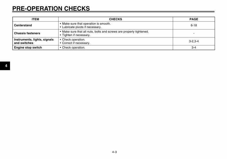
Centerstand• Make sure that operation is smooth.• Lubricate pivots if necessary. 6-18
Chassis fasteners• Make sure that all nuts, bolts and screws are properly tightened.• Tighten if necessary. -
Instruments, lights, signals and switches
• Check operation. • Correct if necessary. 3-2,3-4
Engine stop switch • Check operation. 3-4
ITEM CHECKS PAGE
3B3-F8199-11_ch4.pmd 2007/07/30, 16:353

5-1
1
2
3
4
5
6
7
8
9
OPERATION AND IMPORTANT RIDING POINTSEAU15942
OPERATION AND IMPORTANT RIDING POINTSEAU15980EWA10870
w●●●●● Become thoroughly familiar with
all operating controls and theirfunctions before riding. Consulta Yamaha dealer regarding anycontrol or function that you donot thoroughly understand.
●●●●● Never start the engine or oper-ate it in a closed area for anylength of time. Exhaust fumesare poisonous, and inhalingthem can cause loss of con-sciousness and death within ashort time. Always make surethat there is adequate ventila-tion.
●●●●● For safety, always start the en-gine with the centerstand down.
EAUT2080
Starting a cold engineECA10250
cCSee page 5-3 for engine break-in in-structions prior to operating the ve-hicle for the first time.
1. Turn the key to “ON” and make surethat the engine stop switch is setto “#”.
ECAT1070
cCThe engine trouble warning light andcoolant temperature warning lightshould come on for a few seconds,then go off. If these warning lightsdo not go off, have a Yamaha dealercheck their electrical circuits.
2. Close the throttle completely.3. Start the engine by pushing the
start switch while applying the frontor rear brake.
NOTE:If the engine does not start, release thestart switch, wait a few seconds, andthen try again. Each starting attempt
Starting a cold engine<IXE>
should be as short as possible to pre-serve the battery. Do not crank the en-gine more than 5 seconds on any oneattempt. If the engine does not start withthe star ter motor, try using thekickstarter.
ECA11130
cCFor maximum engine life, alwayswarm the engine up before startingoff. Never accelerate hard when theengine is cold!
3B3-F8199-11_ch5.pmd 2007/07/30, 16:361

5-2
1
2
3
4
5
6
7
8
9
OPERATION AND IMPORTANT RIDING POINTSEAU16760
Starting offNOTE:Before starting off, allow the engine towarm up.
1. While pulling the rear brake leverwith your left hand and holding thegrab bar with your right hand, pushthe scooter off the centerstand.
2. Sit astride the seat, and then ad-just the rear view mirrors.
3. Switch the turn signal on.4. Check for oncoming traffic, and
then slowly turn the throttle grip (onthe right) in order to take off.
5. Switch the turn signal off.
Starting off<IXE>
Braking<IXE>
Acceleration and deceleration<IXE>
EAU16780
Acceleration and deceleration
ZAUM00**
(a)
(b)
The speed can be adjusted by openingand closing the throttle. To increase thespeed, turn the throttle grip in direction(a). To reduce the speed, turn the throttlegrip in direction (b).
EAU16792
Braking1. Close the throttle completely.2. Apply both front and rear brakes
simultaneously while gradually in-creasing the pressure.
EWA10300
w●●●●● Avoid braking hard or suddenly
(especially when leaning over toone side), otherwise the scootermay skid or overturn.
●●●●● Railroad crossings, streetcarrails, iron plates on road con-struction sites, and manholecovers become extremely slip-pery when wet. Therefore, slowdown when approaching suchareas and cross them with cau-tion.
●●●●● Keep in mind that braking on awet road is much more difficult.
●●●●● Ride slowly down a hill, as brak-ing downhill can be very diffi-cult.
3B3-F8199-11_ch5.pmd 2007/07/30, 16:362

5-3
1
2
3
4
5
6
7
8
9
OPERATION AND IMPORTANT RIDING POINTSEAU17212
ParkingWhen parking, stop the engine, andthen remove the key from the mainswitch.
ZAUM00**
Engine break-in<IXE>
Parking<IXE>
EWA10310
w●●●●● Since the engine and exhaust
system can become very hot,park in a place where pedestri-ans or children are not likely totouch them.
●●●●● Do not park on a slope or on softground, otherwise the vehiclemay overturn.
ECA10380
cCNever park in an area where there arefire hazards such as grass or otherflammable materials.
EAU16830
Engine break-inThere is never a more important periodin the life of your engine than the periodbetween 0 and 1000 km (600 mi). Forthis reason, you should read the follow-ing material carefully.
Since the engine is brand new, do notput an excessive load on it for the first1000 km (600 mi). The various parts inthe engine wear and polish themselvesto the correct operating clearances.During this period, prolonged full-throttleoperation or any condition that mightresult in engine overheating must beavoided.
3B3-F8199-11_ch5.pmd 2007/07/30, 16:363
6-1
1
2
3
4
5
6
7
8
9
EAU17226
PERIODIC MAINTENANCE AND MINOR REPAIREAU17226
PERIODIC MAINTENANCE AND MINOR REPAIREAU17301
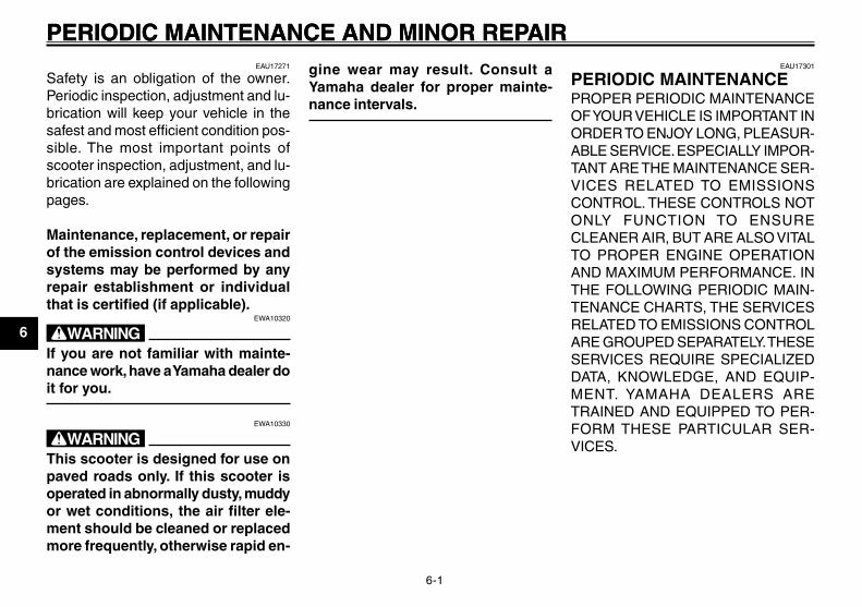
PERIODIC MAINTENANCEPROPER PERIODIC MAINTENANCEOF YOUR VEHICLE IS IMPORTANT INORDER TO ENJOY LONG, PLEASUR-ABLE SERVICE. ESPECIALLY IMPOR-TANT ARE THE MAINTENANCE SER-VICES RELATED TO EMISSIONSCONTROL. THESE CONTROLS NOTONLY FUNCTION TO ENSURECLEANER AIR, BUT ARE ALSO VITALTO PROPER ENGINE OPERATIONAND MAXIMUM PERFORMANCE. INTHE FOLLOWING PERIODIC MAIN-TENANCE CHARTS, THE SERVICESRELATED TO EMISSIONS CONTROLARE GROUPED SEPARATELY. THESESERVICES REQUIRE SPECIALIZEDDATA, KNOWLEDGE, AND EQUIP-MENT. YAMAHA DEALERS ARETRAINED AND EQUIPPED TO PER-FORM THESE PARTICULAR SER-VICES.
Maintenance, periodic<IXE>
EAU17271
Safety is an obligation of the owner.Periodic inspection, adjustment and lu-brication will keep your vehicle in thesafest and most efficient condition pos-sible. The most important points ofscooter inspection, adjustment, and lu-brication are explained on the followingpages.
Maintenance, replacement, or repairof the emission control devices andsystems may be performed by anyrepair establishment or individualthat is certified (if applicable).
EWA10320
wIf you are not familiar with mainte-nance work, have a Yamaha dealer doit for you.
EWA10330
wThis scooter is designed for use onpaved roads only. If this scooter isoperated in abnormally dusty, muddyor wet conditions, the air filter ele-ment should be cleaned or replacedmore frequently, otherwise rapid en-
gine wear may result. Consult aYamaha dealer for proper mainte-nance intervals.
3B3-F8199-11_ch6.pmd 2007/07/30, 16:361

6-2
1
2
3
4
5
6
7
8
9
EAU17226
PERIODIC MAINTENANCE AND MINOR REPAIREAU17560
Periodic maintenance chart for the emission control system
Maintenance, emission control system<IXE>
NO. ITEM ROUTINE
INITIAL ODOMETER READING
600 mi (1,000 km)
or1
month
2,000 mi (4,000 km)
or6
months
4,000 mi (7,000 km)
or12
months
6,000 mi (10,000 km)
or18
months
8,000 mi (13,000 km)
or24
months
10,000 mi (16,000 km)
or30
months
1 * Fuel line• Check fuel and vacuum hoses for
cracks or damage.• Replace if necessary.
2 Spark plug
• Check condition.• Adjust gap and clean.• Replace at 4000 mi (7000 km) or
12 months and thereafter every 4000 mi (6000 km) or 12 months.
Replace. Replace.
3 * Valve clearance • Check and adjust valve clearance when engine is cold. Every 6000 mi (10000 km)
4 *Crankcase breather system
• Check breather hose for cracks or damage.
• Replace if necessary.
5 * Fuel injection • Check engine idle speed.
6 * Exhaust system• Check for leakage.• Tighten if necessary.• Replace gasket(s) if necessary.
7 * Air induction system• Check the air cut-off valve, reed
valve, and hose for damage.• Replace any damaged parts.
* Since these items require special tools, data and technical skills, have a Yamaha dealer perform the service.
3B3-F8199-11_ch6.pmd 2007/07/30, 16:362

6-3
1
2
3
4
5
6
7
8
9
EAU17226
PERIODIC MAINTENANCE AND MINOR REPAIREAU32125
General maintenance and lubrication chart
Maintenance and lubrication, periodic<IXE>
NO. ITEM ROUTINE
INITIAL ODOMETER READING
600 mi(1,000 km)
or1
month
2,000 mi(4,000 km)
or6
months
4,000 mi(7,000 km)
or12
months
6,000 mi(10,000 km)
or18
months
8,000 mi(13,000 km)
or24
months
10,000 mi(16,000 km)
or30
months
1 * Air filter element • Replace.
2 * Front brake• Check operation.• Adjust cable and replace brake
shoes if necessary.
3 * Rear brake• Check operation.• Adjust cable and replace brake
shoes if necessary.
4 * Wheels • Check runout and for damage.• Replace if necessary.
5 * Tires
• Check tread depth and for damage.• Replace if necessary.• Check air pressure.• Correct if necessary.
6 * Wheel bearings• Check bearings for smooth
operation.• Replace if necessary.
7 * Steering bearings
• Check bearing assemblies for looseness.
• Moderately repack with lithium-soap-based grease every 8000 mi (13000 km) or 24 months.
Repack.
8 * Chassis fasteners• Check all chassis fitting and
fasteners.• Correct if necessary.
3B3-F8199-11_ch6.pmd 2007/07/30, 16:363

6-4
1
2
3
4
5
6
7
8
9
EAU17226
PERIODIC MAINTENANCE AND MINOR REPAIR
9 Front brake lever pivot shaft
• Apply lithium-soap-based grease (all-purpose grease) lightly.
10 Rear brake lever pivot shaft
• Apply lithium-soap-based grease (all-purpose grease) lightly.
11 Centerstand • Check operation.• Lubricate.
12 * Front fork• Check operation and for oil
leakage.• Replace if necessary.
13 *Shock absorber assembly
• Check operation and for oil leakage.
• Replace if necessary.
14 Engine oil
• Change (warm engine before draining).
• Check oil level and vehicle for oil leakage.
15 Engine oil strainer • Clean.
16 * Cooling system• Check coolant level and vehicle for
coolant leakage.
• Change. Every 3 years
17 Final transmission oil
• Check vehicle for oil leakage.• Change.
18 * V-belt • Replace. Every 6250 mi (10000 km)
19 *Front and rear brake switches • Check operation.
NO. ITEM ROUTINE
INITIAL ODOMETER READING
600 mi(1,000 km)
or1
month
2,000 mi(4,000 km)
or6
months
4,000 mi(7,000 km)
or12
months
6,000 mi(10,000 km)
or18
months
8,000 mi(13,000 km)
or24
months
10,000 mi(16,000 km)
or30
months
3B3-F8199-11_ch6.pmd 2007/07/30, 16:364

6-5
1
2
3
4
5
6
7
8
9
EAU17226
PERIODIC MAINTENANCE AND MINOR REPAIR
* Since these items require special tools, data and technical skills, have a Yamaha dealer perform the service.
NOTE:From 12000 mi ( 19000 km) or 36 months, repeat the maintenance intervals starting from 4000 mi (7000 km) or 12 months.
20 *Control and meter cables
• Apply Yamaha chain and cable lube or engine oil 10W-30 thoroughly.
21 *Throttle grip housing and cable
• Check operation and free play.• Adjust the throttle cable free play if
necessary.• Lubricate the throttle grip housing
and cable.
22 *Lights, signals and switches
• Check operation.• Adjust headlight beam.
NO. ITEM ROUTINE
INITIAL ODOMETER READING
600 mi(1,000 km)
or1
month
2,000 mi(4,000 km)
or6
months
4,000 mi(7,000 km)
or12
months
6,000 mi(10,000 km)
or18
months
8,000 mi(13,000 km)
or24
months
10,000 mi(16,000 km)
or30
months
3B3-F8199-11_ch6.pmd 2007/07/30, 16:365
6-6
1
2
3
4
5
6
7
8
9
EAU17226
PERIODIC MAINTENANCE AND MINOR REPAIREAU18771
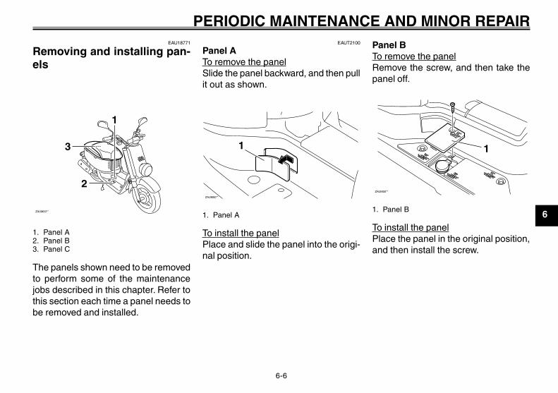
Removing and installing pan-els
ZAUM00**
3
1
2
1. Panel A2. Panel B3. Panel C
The panels shown need to be removedto perform some of the maintenancejobs described in this chapter. Refer tothis section each time a panel needs tobe removed and installed.
Panels, removing and installing<IXE>
EAUT2100
Panel ATo remove the panelSlide the panel backward, and then pullit out as shown.
ZAUM00**
1
1. Panel A
To install the panelPlace and slide the panel into the origi-nal position.
Panel BTo remove the panelRemove the screw, and then take thepanel off.
ZAUM00**
1
1. Panel B
To install the panelPlace the panel in the original position,and then install the screw.
3B3-F8199-11_ch6.pmd 2007/07/30, 16:366

6-7
1
2
3
4
5
6
7
8
9
EAU17226
PERIODIC MAINTENANCE AND MINOR REPAIRPanel CTo remove the panel
ZAUM00**
1
1. Panel C
1. Open the seat. (See page 3-8.)2. Remove the screws, and then take
the panel off.
To install the panelPlace the panel in the original position,and then install the screws.
EAUT2070
Checking the spark plugThe spark plug is an important enginecomponent, which is easy to check.Since heat and deposits will cause anyspark plug to slowly erode, the sparkplug should be removed and checkedin accordance with the periodic main-tenance and lubrication chart. In addi-tion, the condition of the spark plug canreveal the condition of the engine.
To remove the spark plug1. Remove panel A. (See page 6-6.)2. Remove the spark plug cap.
ZAUM00**
1
1. Spark plug wrench
Spark plug, checking<IXE>
3. Remove the spark plug as shown,with a spark plug wrench availableat a Yamaha dealer.
To check the spark plug1. Check that the porcelain insulator
around the center electrode of thespark plug is a medium-to-light tan(the ideal color when the vehicle isridden normally).
NOTE:If the spark plug shows a distinctly dif-ferent color, the engine could be oper-ating improperly. Do not attempt to di-agnose such problems yourself. In-stead, have a Yamaha dealer check thevehicle.
2. Check the spark plug for electrodeerosion and excessive carbon orother deposits, and replace it ifnecessary.
Specified spark plug:CR7E (NGK)
3B3-F8199-11_ch6.pmd 2007/07/30, 16:367

6-8
1
2
3
4
5
6
7
8
9
EAU17226
PERIODIC MAINTENANCE AND MINOR REPAIRTo install the spark plug
1. Measure the spark plug gap with awire thickness gauge and, if nec-essary, adjust the gap to specifi-cation.
Spark plug gap:0.7 ~ 0.8 mm (0.028 ~ 0.031 in)
2. Clean the surface of the spark pluggasket and its mating surface, andthen wipe off any grime from thespark plug threads.
3. Install the spark plug with the sparkplug wrench, and then tighten it tothe specified torque.
Tightening torque:Spark plug:
13 Nm (1.3 m • kgf, 9.4ft • lbf)
NOTE:If a torque wrench is not available wheninstalling a spark plug, a good estimateof the correct torque is 1/4~1/2 turn pastfinger tight. However, the spark plugshould be tightened to the specifiedtorque as soon as possible.
4. Install the spark plug cap.5. Install the panel.
EAUT1460
Engine oil and oil strainerThe engine oil level should be checkedbefore each ride. In addition, the oil mustbe changed and the oil strainer cleanedat the intervals specified in the periodicmaintenance and lubrication chart.
To check the engine oil level1. Place the vehicle on the
centerstand.
NOTE:Make sure that the vehicle is positionedstraight up when checking the oil level.A slight tilt to the side can result in afalse reading.
2. Start the engine, warm it up for sev-eral minutes, and then turn it off.
Engine oil<IXE>
3B3-F8199-11_ch6.pmd 2007/07/30, 16:368

6-9
1
2
3
4
5
6
7
8
9
EAU17226
PERIODIC MAINTENANCE AND MINOR REPAIR
ZAUM00**
1
23
1. Engine oil filler cap2. Maximum level mark3. Minimum level mark
3. Wait a few minutes until the oilsettles, remove the oil filler cap,wipe the dipstick clean, insert itback into the oil filler hole (withoutscrewing it in), and then remove itagain to check the oil level.
NOTE:The engine oil should be between theminimum and maximum level marks.
4. If the engine oil is below the mini-mum level mark, add sufficient oilof the recommended type to raiseit to the correct level.
5. Insert the dipstick into the oil fillerhole, and then tighten the oil fillercap.
To change the engine oil and cleanthe oil strainer
1. Start the engine, warm it up for sev-eral minutes, and then turn it off.
2. Place an oil pan under the engineto collect the used oil.
3. Remove the engine oil filler cap andthe engine oil drain bolts A and Bto drain the oil from the crankcase.
ZAUM00**1
1. Engine oil drain bolt A
ZAUM00**
1
1. Engine oil drain bolt BECAT1020
cCWhen removing the engine oil drainbolt B, the O-ring, compressionspring, and oil strainer will fall out.Take care not to lose these parts.
4. Clean the oil strainer with solvent,and then check it for damage andreplace it if necessary.
5. Check the O-ring for damage andreplace it if necessary.
6. Install the oil strainer, compressionspring, O-ring and engine oil drainbolt B.
3B3-F8199-11_ch6.pmd 2007/07/30, 16:369

6-10
1
2
3
4
5
6
7
8
9
EAU17226
PERIODIC MAINTENANCE AND MINOR REPAIR
NOTE:Make sure that the O-ring is properlyseated.
7. Install engine oil drain bolt A, andthen tighten both drain bolts to theirspecified torques.
Tightening torque:Engine oil drain bolt A:
23 Nm (2.3 m • kgf, 16.6 ft • lbf)Engine oil drain bolt B:
32 Nm (3.2 m • kgf, 23.1 ft • lbt)
ZAUM00**
1
1. Oil filler hole
8. Add the specified amount of therecommended engine oil, and theninstall and tighten the oil filler cap.
Recommended engine oil:See page 8-1.
Oil change quantity:0.78 L (0.82 US qt) (0.69 Imp.qt)
ECA11670
cC●●●●● Do not use oils with a diesel
specification of “CD” or oils of ahigher quality than specified. Inaddition, do not use oils labeled“ENERGY CONSERVING II” orhigher.
●●●●● Be sure no foreign material en-ters the crankcase.
9. Start the engine, and then let it idlefor several minutes while checkingit for oil leakage. If oil is leaking,immediately turn the engine off andcheck for the cause.
10. Turn the engine off, and then checkthe oil level and correct it if neces-sary.
EAUT1560
Final transmission oilThe final transmission case must bechecked for oil leakage before each ride.If any leakage is found, have a Yamahadealer check and repair the scooter. Inaddition, the final transmission oil mustbe changed as follows at the intervalsspecified in the periodic maintenanceand lubrication chart.
1. Start the engine, warm it up byriding the scooter for several min-utes, and then stop the engine.
2. Place the scooter on thecenterstand.
3. Place an oil pan under the finaltransmission case to collect theused oil.
Final transmission oil<IXE>
3B3-F8199-11_ch6.pmd 2007/07/30, 16:3610

6-11
1
2
3
4
5
6
7
8
9
EAU17226
PERIODIC MAINTENANCE AND MINOR REPAIR
ZAUM00**
1
2
1. Final transmission oil filler bolt2. Final transmission oil drain bolt
4. Remove the oil filler bolt and drainbolt to drain the oil from the finaltransmission case.
5. Install the final transmission oildrain bolt, and then tighten it to thespecified torque.
Tightening torque:Final transmission oil drain bolt:
13 Nm (1.3 m • kgf, 9.4 ft • lbf)
6. Add the specified amount of therecommended final transmissionoil, and then install the oil filler boltand tighten it to the specifiedtorque.
Tightening torque:Final transmission oil filler bolt:
23 Nm (2.3 m • kgf, 16.6 ft • lbf)
Recommended final transmissionoil:
See page 8-1.Oil quantity:
0.10 L (0.11 US qt) (0.09 Imp.qt)
EWA11310
w●●●●● Make sure that no foreign mate-
rial enters the final transmissioncase.
●●●●● Make sure that no oil gets on thetire or wheel.
7. Check the final transmission casefor oil leakage. If oil is leaking,check for the cause.
EAU20070
CoolantThe coolant level should be checkedbefore each ride. In addition, the cool-ant must be changed at the intervalsspecified in the periodic maintenanceand lubrication chart.
Coolant<IXE>
EAUT1521
To check the coolant levelThe coolant level should be checked asfollows before each ride. In addition, thecoolant must be changed at the inter-vals specified in the periodic mainte-nance and lubrication chart.
1. Place the vehicle on thecenterstand.
NOTE:● The coolant level must be checked
on a cold engine since the levelvaries with engine temperature.
● Make sure that the vehicle is posi-tioned straight up when checkingthe coolant level. A slight tilt to theside can result in a false reading.
2. Check the coolant level in the cool-ant reservoir.
3B3-F8199-11_ch6.pmd 2007/07/30, 16:3611

6-12
1
2
3
4
5
6
7
8
9
EAU17226
PERIODIC MAINTENANCE AND MINOR REPAIR
NOTE:The coolant should be between theminimum and maximum level marks.
ZAUM00**
12
1. Maximum level mark2. Minimum level mark
ZAUM00**
1
1. Coolant reservoir cap
3. If the coolant is at or below the mini-mum level mark, remove panel Band the reservoir cap. (See page6-6.)
4. Add coolant or distilled water toraise the coolant to the maximumlevel mark, and install the coolantreservoir cap and the panel.
Coolant reservoir capacity (up to themaximum level mark):
0.26 L (0.27 US qt) (0.23 Imp.qt)
ECA10470
cC●●●●● If coolant is not available, use
distilled water or soft tap waterinstead. Do not use hard wateror salt water since it is harmfulto the engine.
●●●●● If water has been used insteadof coolant, replace it with cool-ant as soon as possible, other-wise the engine may not be suf-ficiently cooled and the coolingsystem will not be protectedagainst frost and corrosion.
●●●●● If water has been added to thecoolant, have a Yamaha dealer
check the antifreeze content ofthe coolant as soon as possible,otherwise the effectiveness ofthe coolant will be reduced.
EWA10380
wNever attempt to remove the radia-tor cap when the engine is hot.
NOTE:If the engine overheats, see page 6-27for further instructions.
3B3-F8199-11_ch6.pmd 2007/07/30, 16:3612

6-13
1
2
3
4
5
6
7
8
9
EAU17226
PERIODIC MAINTENANCE AND MINOR REPAIREAUT1990
Replacing the air filter elementThe air filter element must be replacedand the check hoses must be cleanedat the intervals specified in the periodicmaintenance and lubrication chart.Have a Yamaha dealer replace the airfilter element.
Air filter element, replacing<IXE>
Throttle cable free play, checking<IXE>
Valve clearance<IXE>
EAU21401
Valve clearanceThe valve clearance changes with use,resulting in improper air-fuel mixtureand/or engine noise. To prevent this fromoccurring, the valve clearance must beadjusted by a Yamaha dealer at the in-tervals specified in the periodic mainte-nance and lubrication chart.
EAU21382
Checking the throttle cablefree playThe throttle cable free play should mea-sure 1.5 ~ 3.5 mm (0.06 ~ 0.14 in) atthe throttle grip. Periodically check thethrottle cable free play and, if necessary,have a Yamaha dealer adjust it.
3B3-F8199-11_ch6.pmd 2007/07/30, 16:3613

6-14
1
2
3
4
5
6
7
8
9
EAU17226
PERIODIC MAINTENANCE AND MINOR REPAIRTires<IXE>
EAUT2150
TiresTo maximize the performance, durabil-ity, and safe operation of your scooter,note the following points regarding thespecified tires.
Tire air pressureThe tire air pressure should be checkedand, if necessary, adjusted before eachride.
EWA10540
wBecause loading has an enormousimpact on the handling, braking, per-formance and safety characteristicsof your scooter, you should keep thefollowing precautions in mind.
●●●●● NEVER OVERLOAD THESCOOTER! Operation of an over-loaded scooter may result in tiredamage, loss of control, or se-vere injury. Make sure that thetotal weight of rider, cargo, andaccessories does not exceed thespecified maximum load for thevehicle.
●●●●● Improper tire air pressure greatlyaffects tire life and handling.
If the tire air pressure is too high,shocks from the road will not bedampened but instead be trans-mitted to the frame and handle-bars, which impairs riding com-fort. In addition, the scooter willbe unstable in curves.If the tire air pressure is too low,the tires will be damaged and thetire life shortened. In addition,the tires could slip off the wheelrims during braking, whichcould result in tube damage. Thescooter could also easily turnover in a curve.
Tire air pressure* (measured on coldtires):
Front:175 kPa (25 psi) (1.75 kgf/cm2)
Rear:175 kPa (25 psi) (1.75 kgf/cm2)
Tire inspection
ZAUM00**
1
2
1. Tire tread depth2. Tire sidewall
Always check the tires before operat-ing the scooter. If a tire tread showscrosswise lines (minimum tread depth),if the tire has a nail or glass fragmentsin it, or if the sidewall is cracked, con-tact a Yamaha dealer immediately andhave the tire replaced.
Minimum tire tread depth (front andrear):
0.8 mm (0.03 in)
Tire informationThis scooter is equipped with castwheels and tubeless tires.
3B3-F8199-11_ch6.pmd 2007/07/30, 16:3614

6-15
1
2
3
4
5
6
7
8
9
EAU17226
PERIODIC MAINTENANCE AND MINOR REPAIREAU21960
Cast wheelsTo maximize the performance, durabil-ity, and safe operation of your motor-cycle, note the following points regard-ing the specified wheels.
● The wheel rims should be checkedfor cracks, bends or warpage be-fore each ride. If any damage isfound, have a Yamaha dealer re-place the wheel. Do not attempteven the smallest repair to thewheel. A deformed or crackedwheel must be replaced.
● The wheel should be balancedwhenever either the tire or wheelhas been changed or replaced. Anunbalanced wheel can result inpoor performance, adverse han-dling characteristics, and a short-ened tire life.
● Ride at moderate speeds afterchanging a tire since the tire sur-face must first be “broken in” for itto develop its optimal characteris-tics.
Wheels<IXE>
Brake lever free play, adjusting<IXE>
EAU22130
Adjusting the brake lever freeplay
1
ZAUM00**
1. Front brake lever free play
The brake lever free play should mea-sure 10 ~ 20 mm (0.4 ~ 0.8 in) as shown.Periodically check the brake lever freeplay and, if necessary, adjust it as fol-lows.To increase the brake lever free play,turn the adjusting nut at the brake shoeplate in direction (a). To decrease thebrake lever free play, turn the adjustingnut in direction (b).
Front tire:Size:
120/90-10 57JManufacturer/model:
CHENG SHIN / C-6022Rear tire:
Size:120/90-10 57J
Manufacturer/model:CHENG SHIN / C-6022
EWA10580
w●●●●● It is dangerous to ride with a
worn-out tire. When a tire treadbegins to show crosswise lines,have a Yamaha dealer replacethe tire immediately.
●●●●● The replacement of all wheel-and brake-related parts, includ-ing the tires, should be left to aYamaha dealer, who has the nec-essary professional knowledgeand experience.
3B3-F8199-11_ch6.pmd 2007/07/30, 16:3615

6-16
1
2
3
4
5
6
7
8
9
EAU17226
PERIODIC MAINTENANCE AND MINOR REPAIR
ZAUM00**
1
(a) (b)
1. Adjusting nutEWA10650
wIf proper adjustment cannot be ob-tained as described, have a Yamahadealer make this adjustment.
EAU22170
Adjusting the rear brake leverfree play
1
ZAUM00**
1. Rear brake lever free play
The brake lever free play should mea-sure 10 ~ 20 mm (0.4 ~ 0.8 in) as shown.Periodically check the brake lever freeplay and, if necessary, adjust it as fol-lows.To increase the brake lever free play,turn the adjusting nut at the brake shoeplate in direction (a). To decrease thebrake lever free play, turn the adjustingnut in direction (b).
ZAUM00** 1
(b)
(a)
1. Adjusting nutEWA10650
wIf proper adjustment cannot be ob-tained as described, have a Yamahadealer make this adjustment.
Rear brake lever free play, adjusting<IXE>
3B3-F8199-11_ch6.pmd 2007/07/30, 16:3616

6-17
1
2
3
4
5
6
7
8
9
EAU17226
PERIODIC MAINTENANCE AND MINOR REPAIR
Brake shoes, checking<IXE>
Throttle grip and cable, checking and lubricating<IXE>
EAU22361
Checking the front and rearbrake shoes
ZAUM00**
21
1. Wear indicator2. Wear limit line
ZAUM00**
1
2
1. Wear indicator2. Wear limit line
The front and rear brake shoes mustbe checked for wear at the intervalsspecified in the periodic maintenanceand lubrication chart. Each brake is pro-vided with a wear indicator, which al-lows you to check the brake shoe wearwithout having to disassemble thebrake. To check the brake shoe wear,check the position of the wear indicatorwhile applying the brake. If a brake shoehas worn to the point that the wear indi-cator reaches the wear limit line, havea Yamaha dealer replace the brakeshoes as a set.
EAU23111
Checking and lubricating thethrottle grip and cableThe operation of the throttle grip shouldbe checked before each ride. In addi-tion, the cable should be lubricated atthe intervals specified in the periodicmaintenance chart.
3B3-F8199-11_ch6.pmd 2007/07/30, 16:3617

6-18
1
2
3
4
5
6
7
8
9
EAU17226
PERIODIC MAINTENANCE AND MINOR REPAIR
Brake levers, lubricating<IXE>
Centerstand, checking and lubricating<IXE>
Front fork, checking<IXE>
EAU23191
Checking and lubricating thecenterstandThe operation of the centerstand shouldbe checked before each ride, and thepivots and metal-to-metal contact sur-faces should be lubricated if necessary.
EWA11300
wIf the centerstand does not move upand down smoothly, have a Yamahadealer check or repair it.
Recommended lubricant:Lithium-soap-based grease (all-pur-
pose grease)
EAU23271
Checking the front forkThe condition and operation of the frontfork must be checked as follows at theintervals specified in the periodic main-tenance and lubrication chart.
To check the conditionEWA10750
wSecurely support the motorcycle sothat there is no danger of it fallingover.
Check the inner tubes for scratches,damage and excessive oil leakage.
To check the operation1. Place the motorcycle on a level sur-
face and hold it in an upright posi-tion.
2. While applying the front brake,push down hard on the handlebarsseveral times to check if the frontfork compresses and reboundssmoothly.
EAU43630
Lubricating the front and rearbrake leversThe pivoting points of the front and rearbrake levers must be lubricated at theintervals specified in the periodic main-tenance and lubrication chart.
Recommended lubricant:Lithium-soap-based grease (all-pur-pose grease)
3B3-F8199-11_ch6.pmd 2007/07/30, 16:3618

6-19
1
2
3
4
5
6
7
8
9
EAU17226
PERIODIC MAINTENANCE AND MINOR REPAIR
ZAUM00**
ECA10590
cCIf any damage is found or the frontfork does not operate smoothly, havea Yamaha dealer check or repair it.
EAU23280
Checking the steeringWorn or loose steering bearings maycause danger. Therefore, the operationof the steering must be checked as fol-lows at the intervals specified in theperiodic maintenance and lubricationchart.
1. Place a stand under the engine toraise the front wheel off the ground.
EWA10750
wSecurely support the motorcycle sothat there is no danger of it fallingover.
2. Hold the lower ends of the front forklegs and try to move them forwardand backward. If any free play canbe felt, have a Yamaha dealercheck or repair the steering.
Steering, checking<IXE>
ZAUM00**
3B3-F8199-11_ch6.pmd 2007/07/30, 16:3619

6-20
1
2
3
4
5
6
7
8
9
EAU17226
PERIODIC MAINTENANCE AND MINOR REPAIR
Wheel bearings, checking<IXE>
Battery<IXE>
EAU23290
Checking the wheel bearingsThe front and rear wheel bearings mustbe checked at the intervals specified inthe periodic maintenance and lubrica-tion chart. If there is play in the wheelhub or if the wheel does not turnsmoothly, have a Yamaha dealer checkthe wheel bearings.
EAUT2001
Battery
ZAUM00**
1
1. Battery
This model is equipped with a sealed-type (MF) battery, which does not re-quire any maintenance. There is noneed to check the electrolyte or to adddistilled water.
ECA10620
cCNever attempt to remove the batterycell seals, as this would permanentlydamage the battery.
EWA10760
w●●●●● Electrolyte is poisonous and
dangerous since it contains sul-
furic acid, which causes severeburns. Avoid any contact withskin, eyes or clothing and alwaysshield your eyes when workingnear batteries. In case of contact,administer the following FIRSTAID.• EXTERNAL: Flush with
plenty of water.• INTERNAL: Drink large
quantities of water or milkand immediately call aphysician.
• EYES: Flush with water for15 minutes and seek promptmedical attention.
●●●●● Batteries produce explosive hy-drogen gas. Therefore, keepsparks, flames, cigarettes, etc.,away from the battery and pro-vide sufficient ventilation whencharging it in an enclosed space.
●●●●● KEEP THIS AND ALL BATTER-IES OUT OF THE REACH OFCHILDREN.
The battery is located under the seat.
3B3-F8199-11_ch6.pmd 2007/07/30, 16:3620

6-21
1
2
3
4
5
6
7
8
9
EAU17226
PERIODIC MAINTENANCE AND MINOR REPAIRRemove panel C to access the battery.(See page 6-6.)
To charge the batteryHave a Yamaha dealer charge the bat-tery as soon as possible if it seems tohave discharged. Keep in mind that thebattery tends to discharge more quicklyif the vehicle is equipped with optionalelectrical accessories.
To store the battery1. If the vehicle will not be used for
more than one month, remove thebattery, fully charge it, and thenplace it in a cool, dry place.
2. If the battery will be stored for morethan two months, check it at leastonce a month and fully charge it ifnecessary.
3. Fully charge the battery before in-stallation.
4. After installation, make sure thatthe battery leads are properly con-nected to the battery terminals.
ECAT1051
cC●●●●● Always keep the battery
charged. Storing a dischargedbattery can cause permanentbattery damage.
●●●●● To charge a sealed-type (MF)battery, a special (constant-volt-age) battery charger is required.Using a conventional batterycharger will damage the battery.If you do not have access to asealed-type (MF) batterycharger, have a Yamaha dealercharge your battery.
●●●●● After installing the battery, besure to turn the main switchfrom “ON” to “OFF” three timesin 3 seconds intervals to initial-ize the idle speed control sys-tem.
EAUT2021
Replacing the fuse
ZAUM00**
1
1. Fuse
The fuse holder is located beside thebattery. Remove panel C to access thefuse. (See page 6-6.)If the fuse is blown, replace it as follows.
1. Turn the key to “OFF” and turn offall electrical circuits.
2. Remove the blown fuse, and theninstall a new fuse of the specifiedamperage.
Specified fuse:15 A
Fuse, replacing<IXE>
3B3-F8199-11_ch6.pmd 2007/07/30, 16:3621

6-22
1
2
3
4
5
6
7
8
9
EAU17226
PERIODIC MAINTENANCE AND MINOR REPAIRECAT1061
cC●●●●● Do not use a fuse of a higher
amperage rating than recom-mended to avoid causing exten-sive damage to the electricalsystem and possibly a fire.
●●●●● After removing and installing themain fuse, be sure to turn themain switch from “ON” to “OFF”three times in 3 seconds inter-vals to initialize the idle speedcontrol system.
3. Turn the key to “ON” and turn onthe electrical circuits to check if thedevices operate.
4. If the fuse immediately blows again,have a Yamaha dealer check theelectrical system.
EAU23780
Replacing the headlight bulbThis model is equipped with a quartzbulb headlight. If the headlight bulbburns out, replace it as follows.
1. Remove the headlight unit by re-moving the screws.
ZAUM00**
1 2(✕2)
1. Headlight unit2. Screw
2. Disconnect the headlight coupler,and then remove the bulb cover.
Headlight bulb, replacing<IXE>
ZAUM00**
2
1
1. Headlight coupler2. Bulb cover
3. Remove the headlight bulb holderby turning it counterclockwise, andthen remove the defective bulb.
3B3-F8199-11_ch6.pmd 2007/07/30, 16:3622

6-23
1
2
3
4
5
6
7
8
9
EAU17226
PERIODIC MAINTENANCE AND MINOR REPAIR
ZAUM00**
1
1. Headlight bulb holderEWA10790
wHeadlight bulbs get very hot. There-fore, keep flammable products awayfrom a lit headlight bulb, and do nottouch the bulb until it has cooleddown.
4. Place a new headlight bulb into po-sition, and then secure it with thebulb holder.
ECA10660
cCDo not touch the glass part of theheadlight bulb to keep it free fromoil, otherwise the transparency of theglass, the luminosity of the bulb, andthe bulb life will be adversely af-
fected. Thoroughly clean off any dirtand fingerprints on the headlightbulb using a cloth moistened withalcohol or thinner.
5. Install the headlight bulb cover, andthen connect the coupler.
6. Install the headlight unit by install-ing the screws.
7. Have a Yamaha dealer adjust theheadlight beam if necessary.
EAU24131
Replacing the tail/brake lightbulb
1. Remove the tail/brake light lens byremoving the screws.
ZAUM00**
12
1. Tail/brake light lens2. Bulb
2. Remove the defective bulb bypushing it in and turning it counter-clockwise.
3. Insert a new bulb into the socket,push it in, and then turn it clock-wise until it stops.
4. Install the lens by installing thescrews.
ECA10680
cCDo not overtighten the screws, oth-
Tail/brake light bulb, replacing<IXE>
3B3-F8199-11_ch6.pmd 2007/07/30, 16:3623

6-24
1
2
3
4
5
6
7
8
9
EAU17226
PERIODIC MAINTENANCE AND MINOR REPAIRerwise the lens may break. EAU24202
Replacing a turn signal lightbulb
1. Remove the turn signal light lensby removing the screw.
ZAUM00**
21
1. Turn signal light lens2. Bulb
ZAUM00**
1
2
1. Turn signal light lens2. Bulb
2. Remove the defective bulb bypushing it in and turning it counter-clockwise.
3. Insert a new bulb into the socket,push it in, and then turn it clock-wise until it stops.
4. Install the lens by installing thescrew.
ECA11190
cCDo not overtighten the screw, other-wise the lens may break.
Turn signal light bulb, replacing<IXE>
3B3-F8199-11_ch6.pmd 2007/07/30, 16:3624

6-25
1
2
3
4
5
6
7
8
9
EAU17226
PERIODIC MAINTENANCE AND MINOR REPAIRTroubleshooting<IXE>
EAU25880
TroubleshootingAlthough Yamaha scooters receive athorough inspection before shipmentfrom the factory, trouble may occur dur-ing operation. Any problem in the fuel,compression, or ignition systems, forexample, can cause poor starting andloss of power.
The following troubleshooting chartsrepresent quick and easy proceduresfor checking these vital systems your-self. However, should your scooter re-quire any repair, take it to a Yamahadealer, whose skilled technicians havethe necessary tools, experience, andknow-how to service the scooter prop-erly.
Use only genuine Yamaha replacementparts. Imitation parts may look likeYamaha parts, but they are often infe-rior, have a shorter service life and canlead to expensive repair bills.
3B3-F8199-11_ch6.pmd 2007/07/30, 16:3625

6-26
1
2
3
4
5
6
7
8
9
EAU17226
PERIODIC MAINTENANCE AND MINOR REPAIRTroubleshooting charts<IXE>
EAU42700
Troubleshooting chartsStarting problems or poor engine performance
EWA10840
wKeep away open flames and do not smoke while checking or working on the fuel system.
Check the fuel level inthe fuel tank.
1. FuelThere is enough fuel.
There is no fuel.
Check the compression.
Supply fuel. The engine does not start. Check the compression.
Operate the electric starter.
2. CompressionThere is compression.
There is no compression.
Check the ignition.
Have a Yamaha dealercheck the vehicle.
3. Ignition Wipe off with a dry cloth and correct thespark plug gaps, or replace the spark plug.
Have a Yamaha dealer check the vehicle.
The engine does not start.Have a Yamaha dealercheck the vehicle.
The engine does not start.Check the battery.
Operate the electric starter.
4. BatteryThe engine turns over quickly.
The engine turns over slowly.
The battery is good.
Check the battery lead connections,and charge the battery if necessary.
Dry
WetOperate the electric starter.
Remove the spark plug and check the electrodes.
3B3-F8199-11_ch6.pmd 2007/07/30, 16:3626

6-27
1
2
3
4
5
6
7
8
9
EAU17226
PERIODIC MAINTENANCE AND MINOR REPAIREngine overheating
EWAT1040
w●●●●● Do not remove the radiator cap when the engine and radiator are hot. Scalding hot fluid and steam may be
blown out under pressure, which could cause serious injury. Be sure to wait until the engine has cooled.●●●●● Place a thick rag, like a towel, over the radiator cap, and then slowly rotate the cap counterclockwise to the
detent to allow any residual pressure to escape. When the hissing sound has stopped, press down on the capwhile turning it counterclockwise, and then remove the cap.
NOTE:If coolant is not available, tap water can be temporarily used instead, provided that it is changed to the recommendedcoolant as soon as possible.
Wait until the engine has cooled.
Check the coolant level in the reservoir and radiator.
The coolant level is OK.
The coolant level is low.Check the cooling systemfor leakage.
Have a Yamaha dealer checkand repair the cooling system.
Add coolant. (See NOTE.)
Start the engine. If the engine overheats again, have a Yamaha dealer check and repair the cooling system.
There isleakage.
There is no leakage.
3B3-F8199-11_ch6.pmd 2007/07/30, 16:3627
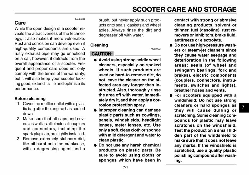
7-1
1
2
3
4
5
6
7
8
9
SCOOTER CARE AND STORAGECare<IXE>
EAU25991
SCOOTER CARE AND STORAGEEAU26091
CareWhile the open design of a scooter re-veals the attractiveness of the technol-ogy, it also makes it more vulnerable.Rust and corrosion can develop even ifhigh-quality components are used. Arusty exhaust pipe may go unnoticedon a car, however, it detracts from theoverall appearance of a scooter. Fre-quent and proper care does not onlycomply with the terms of the warranty,but it will also keep your scooter look-ing good, extend its life and optimize itsperformance.
Before cleaning1. Cover the muffler outlet with a plas-
tic bag after the engine has cooleddown.
2. Make sure that all caps and cov-ers as well as all electrical couplersand connectors, including thespark plug cap, are tightly installed.
3. Remove extremely stubborn dirt,like oil burnt onto the crankcase,with a degreasing agent and a
brush, but never apply such prod-ucts onto seals, gaskets and wheelaxles. Always rinse the dirt anddegreaser off with water.
CleaningECA10781
cC●●●●● Avoid using strong acidic wheel
cleaners, especially on spokedwheels. If such products areused on hard-to-remove dirt, donot leave the cleaner on the af-fected area any longer than in-structed. Also, thoroughly rinsethe area off with water, immedi-ately dry it, and then apply a cor-rosion protection spray.
●●●●● Improper cleaning can damageplastic parts such as cowlings,panels, windshields, headlightlenses, meter lenses, etc. Useonly a soft, clean cloth or spongewith mild detergent and water toclean plastic.
●●●●● Do not use any harsh chemicalproducts on plastic parts. Besure to avoid using cloths orsponges which have been in
contact with strong or abrasivecleaning products, solvent orthinner, fuel (gasoline), rust re-movers or inhibitors, brake fluid,antifreeze or electrolyte.
●●●●● Do not use high-pressure wash-ers or steam-jet cleaners sincethey cause water seepage anddeterioration in the followingareas: seals (of wheel andswingarm bearings, fork andbrakes), electric components(couplers, connectors, instru-ments, switches and lights),breather hoses and vents.
●●●●● For scooters equipped with awindshield: Do not use strongcleaners or hard sponges asthey will cause dulling orscratching. Some cleaning com-pounds for plastic may leavescratches on the windshield.Test the product on a small hid-den part of the windshield tomake sure that it does not leaveany marks. If the windshield isscratched, use a quality plasticpolishing compound after wash-ing.
3B3-F8199-11_ch7.pmd 2007/07/30, 16:371

7-2
1
2
3
4
5
6
7
8
9
SCOOTER CARE AND STORAGEAfter normal useRemove dirt with warm water, a milddetergent, and a soft, clean sponge, andthen rinse thoroughly with clean water.Use a toothbrush or bottlebrush forhard-to-reach areas. Stubborn dirt andinsects will come off more easily if thearea is covered with a wet cloth for afew minutes before cleaning.
After riding in the rain, near the sea oron salt-sprayed roadsSince sea salt or salt sprayed on theroads during winter are extremely cor-rosive in combination with water, carryout the following steps after each ridein the rain, near the sea or on salt-sprayed roads.
NOTE:Salt sprayed on roads in the winter mayremain well into spring.
1. Clean the scooter with cold waterand a mild detergent after the en-gine has cooled down.
ECA10790
cCDo not use warm water since it in-creases the corrosive action of thesalt.
2. Apply a corrosion protection sprayon all metal, including chrome- andnickel-plated, surfaces to preventcorrosion.
After cleaning1. Dry the scooter with a chamois or
an absorbing cloth.2. Use a chrome polish to shine
chrome, aluminum and stainless-steel parts, including the exhaustsystem. (Even the thermally in-duced discoloring of stainless-steelexhaust systems can be removedthrough polishing.)
3. To prevent corrosion, it is recom-mended to apply a corrosion pro-tection spray on all metal, includ-ing chrome- and nickel-plated, sur-faces.
4. Use spray oil as a universal cleanerto remove any remaining dirt.
5. Touch up minor paint damagecaused by stones, etc.
6. Wax all painted surfaces.7. Let the scooter dry completely be-
fore storing or covering it.EWA10940
w●●●●● Make sure that there is no oil or
wax on the brakes or tires. If nec-essary, clean the brake discsand brake linings with a regularbrake disc cleaner or acetone,and wash the tires with warmwater and a mild detergent.
●●●●● Before operating the scootertest its braking performance andcornering behavior.
ECA10800
cC●●●●● Apply spray oil and wax spar-
ingly and make sure to wipe offany excess.
●●●●● Never apply oil or wax to anyrubber and plastic parts, buttreat them with a suitable careproduct.
●●●●● Avoid using abrasive polishingcompounds as they will wear
3B3-F8199-11_ch7.pmd 2007/07/30, 16:372

7-3
1
2
3
4
5
6
7
8
9
SCOOTER CARE AND STORAGEEAU36560
StorageShort-termAlways store your scooter in a cool, dryplace and, if necessary, protect itagainst dust with a porous cover.
ECA10820
cC●●●●● Storing the scooter in a poorly
ventilated room or covering itwith a tarp, while it is still wet,will allow water and humidity toseep in and cause rust.
●●●●● To prevent corrosion, avoiddamp cellars, stables (becauseof the presence of ammonia) andareas where strong chemicalsare stored.
Long-termBefore storing your scooter for severalmonths:
1. Follow all the instructions in the“Care” section of this chapter.
2. Fill up the fuel tank and add fuelstabilizer (if available) to prevent thefuel tank from rusting and the fuelfrom deteriorating.
Storage<IXE>
3. Perform the following steps to pro-tect the cylinder, piston rings, etc.from corrosion.a. Remove the spark plug cap and
spark plug.b. Pour a teaspoonful of engine oil
into the spark plug bore.c. Install the spark plug cap onto
the spark plug, and then placethe spark plug on the cylinderhead so that the electrodes aregrounded. (This will limit spark-ing during the next step.)
d. Turn the engine over severaltimes with the starter. (This willcoat the cylinder wall with oil.)
e. Remove the spark plug cap fromthe spark plug, and then installthe spark plug and the spark plugcap.
EWA10950
wTo prevent damage or injury fromsparking, make sure to ground thespark plug electrodes while turningthe engine over.
away the paint.
NOTE:Consult a Yamaha dealer for advice onwhat products to use.
3B3-F8199-11_ch7.pmd 2007/07/30, 16:373

7-4
1
2
3
4
5
6
7
8
9
SCOOTER CARE AND STORAGE4. Lubricate all control cables and the
pivoting points of all levers andpedals as well as of the sidestand/centerstand.
5. Check and, if necessary, correctthe tire air pressure, and then liftthe scooter so that both of itswheels are off the ground. Alterna-tively, turn the wheels a little everymonth in order to prevent the tiresfrom becoming degraded in onespot.
6. Cover the muffler outlet with a plas-tic bag to prevent moisture from en-tering it.
7. Remove the battery and fullycharge it. Store it in a cool, dryplace and charge it once a month.Do not store the battery in an ex-cessively cold or warm place [lessthan 0 °C (30 °F) or more than 30°C (90 °F)]. For more informationon storing the battery, see page 6-21.
NOTE:Make any necessary repairs beforestoring the scooter.
3B3-F8199-11_ch7.pmd 2007/07/30, 16:374

8-1
1
2
3
4
5
6
7
8
9
SPECIFICATIONSSpecifications<IXE>
EAU26320
SPECIFICATIONSDimensions
Overall length1905 mm (75.0 in)
Overall width685 mm (27.0 in)
Overall height1045 mm (41.1 in)
Seat height735 mm (28.9 in)
Wheelbase1280 mm (50.4 in)
Ground clearance115 mm (4.53 in)
Minimum turning radius2000 mm (78.7 in)
WeightWith oil and fuel
90.0 kg (198 lb)Engine
Engine typeLiquid cooled 4-stroke, SOHC
Cylinder arrangementForward-inclined single cylinder
Displacement49.0 cm3
Bore x stroke38.0 x 43.5 mm (1.50 x 1.71 in)
Compression ratio12.00 :1
Starting systemElectric starter and kickstarter
Lubrication systemWet sump
Engine oilType
SAE10W30 or SAE10W40
10 30 50 70 90 1100 130 ˚F
-10 0 10 20 30 40-20 50 ˚C
or SAE 10W-30YAMALUBE 4 (10W-30)
YAMALUBE 4 (20W-40)or SAE 20W-40
Recommended engine oil gradeAPI service SG type or higher, JASOstandard MA
Periodic oil change0.78 L (0.82 US qt) (0.69 Imp.qt)
Final transmission oilType
SAE10W30 type SE motor oilQuantity
0.10 L (0.11 US qt) (0.09 Imp.qt)Cooling system
Coolant reservoir capacity (up to the maxi-mum level mark)
0.26 L (0.27 US qt) (0.23 Imp.qt)Radiator capacity (including all routes)
0.50 L (0.53 US qt) (0.44 Imp.qt)Air filter
Air filter elementWet element
FuelRecommended fuel
Unleaded gasoline only
Fuel tank capacity4.5 L (1.19 US gal) (0.99 Imp.gal)
Fuel injectorManufacturer
AISAN INDUSTRYModel/quantity
3B3 / 1Spark plug (s)
Manufacturer/modelNGK/CR7E
Spark plug gap0.7-0.8 mm (0.028-0.031 in)
ClutchClutch type
Dry, centrifugal automaticTransmission
Primary reduction systemHelical gear
Primary reduction ratio50/13 (3.846)
Secondary reduction systemHelical gear
Secondary reduction ratio43/12 (3.583)
Transmission typeV-belt automatic
OperationCentrifugal automatic type
ChassisFrame type
Steel tube backboneCaster angle
26.00 degree
3B3-F8199-11_ch8.pmd 2007/07/30, 16:371

8-2
1
2
3
4
5
6
7
8
9
SPECIFICATIONSTrail
84.0 mm (3.31 in)Front tire
TypeTubeless
Size120/90-10 57J
Manufacturer/modelCHENG SHIN / C-6022
Rear tireType
TubelessSize
120/90-10 57JManufacturer/model
CHENG SHIN / C-6022Maximum load
85 kg (187 lb)Tire air pressure (measured on coldtires)
Loading condition0-85 kg (0-187 lb)
Front175 kPa (25 psi) (1.75 kgf/cm2) (1.75 bar)
Rear175 kPa (25 psi) (1.75 kgf/cm2) (1.75 bar)
Front wheelWheel type
Cast wheelRim size
10 x MT 3.00Rear wheel
Wheel typeCast wheel
Rim size10 x MT 3.00
Front brakeType
Drum brakeOperation
Right hand operationRear brake
TypeDrum brake
OperationLeft hand operation
Front suspensionType
Telescopic forkSpring/shock absorber type
Coil springWheel travel
58.0 mm (2.28 in)Rear suspension
TypeUnit swing
Spring/shock absorber typeCoil spring
Wheel travel56.0 mm (2.20 in)
Electrical systemIgnition system
Transistorized coil ignitionCharging system
AC magnetoBattery
ModelGTX5L-BS
Voltage, capacity12 V, 4.0 Ah
HeadlightBulb type
Halogen bulbBulb voltage, wattage x quantity
Headlight12 V, 35 W/35.0 W x 1
Tail/brake light12 V, 5.0 W/21.0 W x 1
Front turn signal light12 V, 10.0 W x 2
Rear turn signal light12 V, 10.0 W x 2
License plate light12 V, 5.0 W x 1
Meter lighting12 V, 1.7 W x 1
High beam indicator light12 V, 1.7 W x 1
Turn signal indicator light14 V, 3.0 W x 1
Coolant temperature warning light12 V, 1.7 W x 1
Engine trouble warning light12 V, 1.7 W x 1
FusesMain fuse
15.0 A
3B3-F8199-11_ch8.pmd 2007/07/30, 16:372
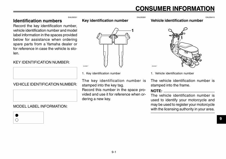
9-1
1
2
3
4
5
6
7
8
9
CONSUMER INFORMATIONEAU26351
Identification numbersRecord the key identification number,vehicle identification number and modellabel information in the spaces providedbelow for assistance when orderingspare parts from a Yamaha dealer orfor reference in case the vehicle is sto-len.
KEY IDENTIFICATION NUMBER:
VEHICLE IDENTIFICATION NUMBER:
MODEL LABEL INFORMATION:
Identification numbers<IXE>
Key identification number<IXE>
Vehicle identification number<IXE>
EAU26381
Key identification number
ZAUM00**
1
1. Key identification number
The key identification number isstamped into the key tag.Record this number in the space pro-vided and use it for reference when or-dering a new key.
EAU26342
CONSUMER INFORMATIONEAU26410
Vehicle identification number
ZAUM00**
1
1. Vehicle identification number
The vehicle identification number isstamped into the frame.
NOTE:The vehicle identification number isused to identify your motorcycle andmay be used to register your motorcyclewith the licensing authority in your area.
3B3-F8199-11_ch9ind.pmd 2007/07/30, 16:371
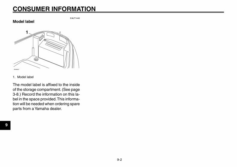
9-2
1
2
3
4
5
6
7
8
9
CONSUMER INFORMATIONEAUT1440
Model label
ZAUM00**
1
1. Model label
The model label is affixed to the insideof the storage compartment. (See page3-8.) Record the information on this la-bel in the space provided. This informa-tion will be needed when ordering spareparts from a Yamaha dealer.
Model label<IXE>
3B3-F8199-11_ch9ind.pmd 2007/07/30, 16:372

9-3
1
2
3
4
5
6
7
8
9
CONSUMER INFORMATIONSafety defects, reporting<IXE>
EAU26551
Reporting safety defectsIf you believe that your vehicle has a defect which could cause a crash or could cause injury or death, you should immedi-ately inform the National Highway Traffic Safety Administration (NHTSA) in addition to notifying Yamaha Motor Corporation,U.S.A. If NHTSA receives similar complaints, it may open an investigation, and if it finds that a safety defect exists in a groupof vehicles, it may order a recall and remedy campaign. However, NHTSA cannot become involved in individual problemsbetween you, your dealer, or Yamaha Motor Corporation, U.S.A.
To contact NHTSA, you may call the Vehicle Safety Hotline toll-free at 1-888-327-4236 (TTY: 1-800-424-9153); go to http://www.safercar.gov; or write to: Administrator, NHTSA, 400 Seventh Street, SW., Washington, DC 20590. You can also obtainother information about motor vehicle safety from http://www.safercar.gov.
3B3-F8199-11_ch9ind.pmd 2007/07/30, 16:373
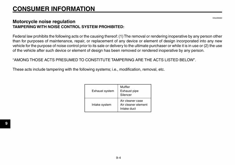
9-4
1
2
3
4
5
6
7
8
9
CONSUMER INFORMATIONEAU26560
Motorcycle noise regulationTAMPERING WITH NOISE CONTROL SYSTEM PROHIBITED:
Federal law prohibits the following acts or the causing thereof: (1) The removal or rendering inoperative by any person otherthan for purposes of maintenance, repair, or replacement of any device or element of design incorporated into any newvehicle for the purpose of noise control prior to its sale or delivery to the ultimate purchaser or while it is in use or (2) the useof the vehicle after such device or element of design has been removed or rendered inoperative by any person.
“AMONG THOSE ACTS PRESUMED TO CONSTITUTE TAMPERING ARE THE ACTS LISTED BELOW”.
These acts include tampering with the following systems; i.e., modification, removal, etc.
Noise regulation<IXE>
Exhaust systemMufflerExhaust pipeSilencer
Intake systemAir cleaner caseAir cleaner elementIntake duct
3B3-F8199-11_ch9ind.pmd 2007/07/30, 16:374

9-5
1
2
3
4
5
6
7
8
9
CONSUMER INFORMATIONEAU26600
Maintenance recordCopies of work orders and/or receipts for parts purchased and installed on your motorcycle will be required to documentthat maintenance has been completed in accordance with the emissions warranty. The chart below is printed only as areminder that maintenance work is required. It is not acceptable proof of maintenance work.
Maintenance record<IXE>
Maintenanceinterval
Date ofservice
MileageServicing dealer
name and addressRemarks
600 mi(1000 km) or
1 month
2000 mi(4000 km) or
6 months
4000 mi(7000 km) or12 months
6000 mi(10000 km) or
18 months
8000 mi(13000 km) or
24 months
10000 mi(16000 km) or
30 months
12000 mi(19000 km) or
36 months
14000 mi(22000 km) or
42 months
3B3-F8199-11_ch9ind.pmd 2007/07/30, 16:375
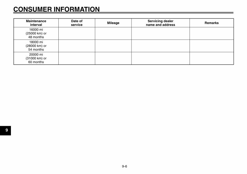
9-6
1
2
3
4
5
6
7
8
9
CONSUMER INFORMATION
16000 mi(25000 km) or
48 months
18000 mi(28000 km) or
54 months
20000 mi(31000 km) or
60 months
Maintenanceinterval
Date ofservice
MileageServicing dealer
name and addressRemarks
3B3-F8199-11_ch9ind.pmd 2007/07/30, 16:376

9-7
1
2
3
4
5
6
7
8
9
CONSUMER INFORMATIONEAU26681
YAMAHA MOTOR CORPORATION, U.S.A.RIVA LIMITED WARRANTY
Warranty, limited<IXE>
3B3-F8199-11_ch9ind.pmd 2007/07/30, 16:377

9-8
1
2
3
4
5
6
7
8
9
CONSUMER INFORMATION
3B3-F8199-11_ch9ind.pmd 2007/07/30, 16:378

9-9
1
2
3
4
5
6
7
8
9
CONSUMER INFORMATIONEAU26750
YAMAHA EXTENDED SERVICE (Y.E.S.)
Warranty, extended<IXE>
Keep your Yamaha protected even after your warranty expires with genuine Yamaha Extended Service (Y.E.S.).
Y.E.S. is designed and administered by Yamaha Motor Corporation to provide maximum owner satisfaction. You get uninterrupted factory-backed coverage for extra peace of mind.
Y.E.S. is flexible. You choose the plan that’s right foryou: 12 months, 24 months, 36 months or, on certain models, even 48 months beyond your warranty period.
Y.E.S. is designed and administered by the same Yamaha people who handle your warranty – and itshows in the comprehensive coverage benefits. There are no mileage limitations. Coverage isn’t limited to “moving parts” or the “drive train” like many other plans. And Y.E.S. covers manufacturing defects just like the warranty. See the sample contract at your Yamahadealer to see how comforting uninterrupted factory-backed protection can be.
You don’t have to pay anything for covered repairs. There’s no deductible to pay, and repairs aren’t“pro-rated.” You don’t have any “out-of-pocket” expenses for covered repairs.
In addition, Travel and Recreation Interruption Protection (TRIP) is included at no extra cost. TRIP gives you up to $150 reimbursement per occurrence for any reasonable expenses you incur because your Yamaha needs covered service: replacement vehicle rental, emergency towing, phone calls, even food and lodging when you are away from home. This superb coverage goes into effect when you purchase Y.E.S., so it applies to any warranty repairs as well as covered repairs during your entire Y.E.S. plan period.
Y.E.S. coverage is honored at any authorized Yamaha dealer nationwide.
Y.E.S. coverage is transferable to a new owner if yousell or trade-in. That can make your Yamaha much more valuable!
This excellent Y.E.S. plan coverage is only available to Yamaha owners like you, and only while your Yamaha is still within the Yamaha Limited Warranty period. So visit your authorized Yamaha dealer to get all the facts. He can show you how easy it is to protect your investment with Yamaha Extended Service.
3B3-F8199-11_ch9ind.pmd 2007/07/30, 16:379

9-10
1
2
3
4
5
6
7
8
9
CONSUMER INFORMATION
We urge you to act now. You’ll get the excellent benefits of TRIP coverage right away, and you’ll rest easy knowing you’ll have strong factory-backed protection even after your Yamaha Limited Warranty expires.
A special note:If visiting your dealer isn’t convenient, contact Yamaha with your Primary ID number (your frame number). We’ll be happy to help you get the Y.E.S. coverage you need.
Yamaha Service MarketingP.O. Box 6555Cypress, CA 906301-(866)-YES-EXTD (1-866-937-3983)
3B3-F8199-11_ch9ind.pmd 2007/07/30, 16:3710

INDEXA
Acceleration and deceleration ................. 5-2Air filter element, replacing .................... 6-13
BBattery .................................................... 6-20Brake lever free play, adjusting .............. 6-15Brake lever, front ...................................... 3-5Brake lever, rear ....................................... 3-5Brake levers, lubricating ......................... 6-18Brake shoes, checking ........................... 6-17Braking ..................................................... 5-2
CCare .......................................................... 7-1Catalytic converters ................................. 3-7Centerstand, checking and lubricating .. 6-18Coolant ................................................... 6-11Coolant temperature warning light ........... 3-2
DDimmer switch .......................................... 3-4
EEngine break-in ........................................ 5-3Engine oil ................................................. 6-8Engine stop switch ................................... 3-4Engine trouble warning light .................... 3-3
FFinal transmission oil ............................. 6-10Front fork, checking ............................... 6-18Fuel .......................................................... 3-6Fuel gauge ............................................... 3-3Fuel tank cap ........................................... 3-5Fuse, replacing ...................................... 6-21
HHandlebar switches .................................. 3-4Headlight bulb, replacing ....................... 6-22
Helmet holder ........................................... 3-8High beam indicator light ......................... 3-2Horn switch .............................................. 3-4
IIdentification numbers .............................. 9-1Indicator and warning lights ..................... 3-2
KKey identification number ......................... 9-1Keyhole cover ........................................... 3-2Kickstarter ................................................ 3-7
LLabels, location of .................................... 1-5Luggage hook .......................................... 3-8
MMain switch/steering lock ......................... 3-1Maintenance and lubrication, periodic ..... 6-3Maintenance record ................................. 9-5Maintenance, emission control system ... 6-2Maintenance, periodic .............................. 6-1Model label ............................................... 9-2
NNoise regulation ....................................... 9-4
PPanels, removing and installing ............... 6-6Parking ..................................................... 5-3Part locations ........................................... 2-1Pre-operation check list ........................... 4-2
RRear brake lever free play, adjusting ..... 6-16
SSafe-riding points ..................................... 1-4Safety defects, reporting .......................... 9-3Seat .......................................................... 3-8Spark plug, checking ............................... 6-7
Specifications ........................................... 8-1Speedometer unit ..................................... 3-3Start switch .............................................. 3-4Starting a cold engine .............................. 5-1Starting off ................................................ 5-2Steering, checking ................................. 6-19Storage ..................................................... 7-3Storage compartment .............................. 3-9
TTail/brake light bulb, replacing ................ 6-23Throttle cable free play, checking .......... 6-13Throttle grip and cable, checking and lubricat-
ing ........................................................ 6-17Tires ....................................................... 6-14Troubleshooting ...................................... 6-25Troubleshooting charts ........................... 6-26Turn signal indicator light ......................... 3-2Turn signal light bulb, replacing ............. 6-24Turn signal switch ..................................... 3-4
VValve clearance ...................................... 6-13Vehicle identification number ................... 9-1
WWarranty, extended .................................. 9-9Warranty, limited ....................................... 9-7Wheel bearings, checking ...................... 6-20Wheels ................................................... 6-15
3B3-F8199-11_ch9ind.pmd 2007/08/01, 10:5711

INDEX
3B3-F8199-11_ch9ind.pmd 2007/07/30, 16:3712

1
2
3
4
5
6
7
8
9
3B3-F8199-11_ch9ind.pmd 2007/07/30, 16:3713

1
2
3
4
5
6
7
8
9
3B3-F8199-11_ch9ind.pmd 2007/07/30, 16:3714

1
2
3
4
5
6
7
8
9
3B3-F8199-11_ch9ind.pmd 2007/07/30, 16:3715

YAMAHA MOTOR TAIWAN CO., LTD
PRINTED IN TAIWAN2007.09-0.8×××××1!
(E)
3B3-F8199-11_Cv.pmd 2007/07/30, 16:381