Embed Size (px)
Citation preview
Products Solutions ServicesBA00200C/07/EN/14.1371212639
valid as of:software version 2.42
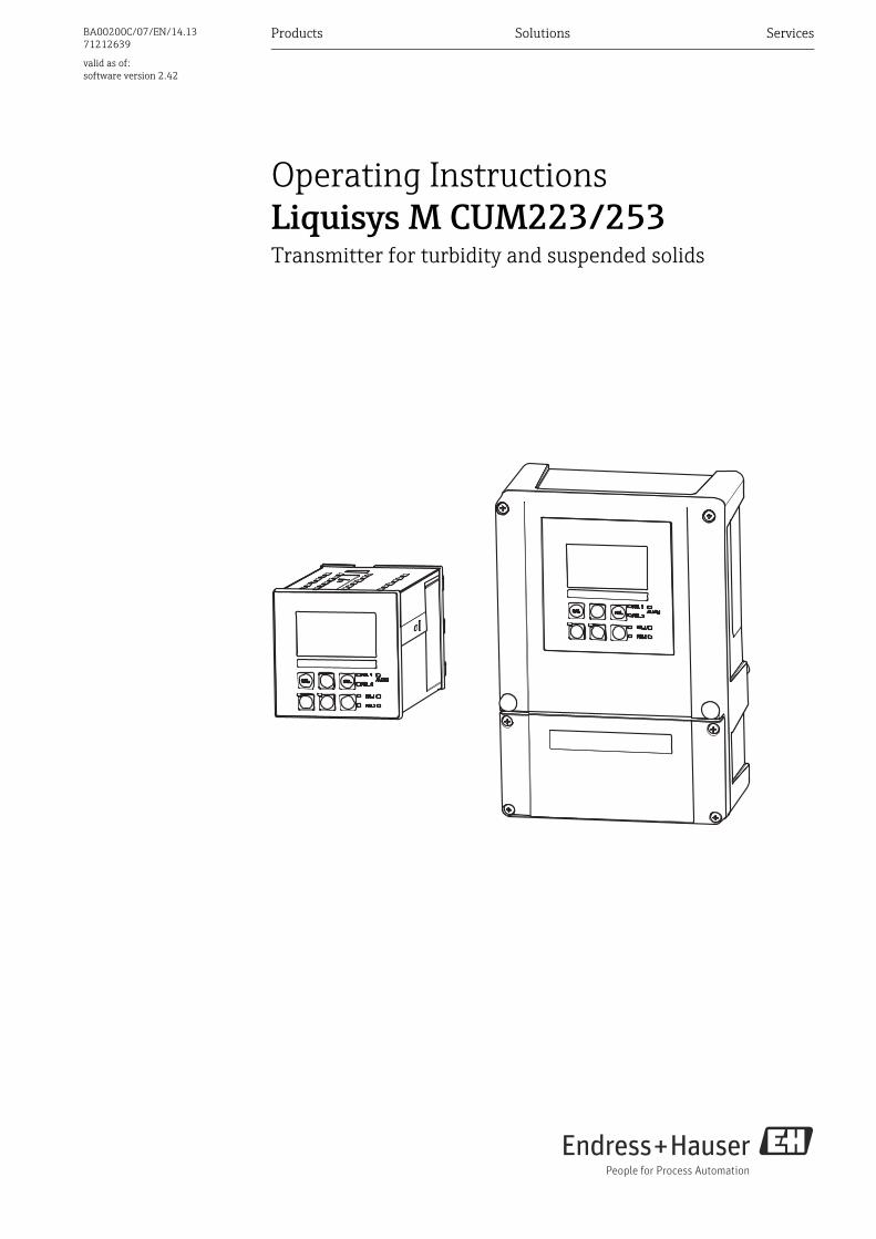
Operating InstructionsLiquisys M CUM223/253Transmitter for turbidity and suspended solids
Endress+Hauser
About this document
Safety messagesThe structure, signal words and safety colors of the signs comply with the specifications of ANSI Z535.6 ("Product safety information in product manuals, instructions and other collateral materials").
Symbols
Safety message structure Meaning
DANGER!
Cause (/consequences)Consequences if safety message is not heeded‣ Corrective action
This symbol alerts you to a dangerous situation.Failure to avoid the situation will result in a fatal or serious injury.
WARNING!
Cause (/consequences)Consequences if safety message is not heeded‣ Corrective action
This symbol alerts you to a dangerous situation.Failure to avoid the situation can result in a fatal or serious injury.
CAUTION!
Cause (/consequences)Consequences if safety message is not heeded‣ Corrective action
This symbol alerts you to a dangerous situation.Failure to avoid this situation can result in minor or medium injury.
NOTICECause/situationConsequences if safety message is not heeded‣ Action/note
This symbol alerts you to situations that can result in damage to property and equipment.
Additional information, tips
Permitted or recommended
Forbidden or not recommended
Liquisys M CUM223/253
Endress+Hauser 3
Table of contents
1 Basic safety instructions . . . . . . . . . . . . . 51.1 Requirements for the personnel . . . . . . . . . . . . . . . 51.2 Designated use . . . . . . . . . . . . . . . . . . . . . . . . . . . . . 51.3 Workplace safety . . . . . . . . . . . . . . . . . . . . . . . . . . . 51.4 Operational safety . . . . . . . . . . . . . . . . . . . . . . . . . . . 51.5 Product safety . . . . . . . . . . . . . . . . . . . . . . . . . . . . . . 61.6 Electrical symbols . . . . . . . . . . . . . . . . . . . . . . . . . . . 6
2 Incoming acceptance and product identification . . . . . . . . . . . . . . . . . . . . . . 7
2.1 Incoming acceptance . . . . . . . . . . . . . . . . . . . . . . . . 72.2 Scope of delivery . . . . . . . . . . . . . . . . . . . . . . . . . . . . 72.3 Product identification . . . . . . . . . . . . . . . . . . . . . . . . 8
2.3.1 Nameplate . . . . . . . . . . . . . . . . . . . . . . . . . . . 82.3.2 Identifying the product . . . . . . . . . . . . . . . . 8
2.4 Certificates and approvals . . . . . . . . . . . . . . . . . . . . 82.4.1 CE mark . . . . . . . . . . . . . . . . . . . . . . . . . . . . . 82.4.2 CSA general purpose . . . . . . . . . . . . . . . . . . 8
3 Installation . . . . . . . . . . . . . . . . . . . . . . . . 93.1 Quick installation guide . . . . . . . . . . . . . . . . . . . . . . 9
3.1.1 Measuring system . . . . . . . . . . . . . . . . . . . . 93.2 Installation conditions . . . . . . . . . . . . . . . . . . . . . 10
3.2.1 Field instrument . . . . . . . . . . . . . . . . . . . . 103.2.2 Panel-mounted instrument . . . . . . . . . . . 11
3.3 Installation instructions . . . . . . . . . . . . . . . . . . . . 123.3.1 Field instrument . . . . . . . . . . . . . . . . . . . . 123.3.2 Panel-mounted instrument . . . . . . . . . . . 15
3.4 Post-installation check . . . . . . . . . . . . . . . . . . . . . 15
4 Electrical connection . . . . . . . . . . . . . . . 164.1 Wiring . . . . . . . . . . . . . . . . . . . . . . . . . . . . . . . . . . 16
4.1.1 Electrical connection . . . . . . . . . . . . . . . . 174.1.2 Measuring cable and sensor connection 194.1.3 Alarm contact . . . . . . . . . . . . . . . . . . . . . . 21
4.2 Post-connection check . . . . . . . . . . . . . . . . . . . . . 21
5 Operability. . . . . . . . . . . . . . . . . . . . . . . . 225.1 Quick operation guide . . . . . . . . . . . . . . . . . . . . . 225.2 Display and operating elements . . . . . . . . . . . . . 22
5.2.1 Display . . . . . . . . . . . . . . . . . . . . . . . . . . . . 225.2.2 Operating elements . . . . . . . . . . . . . . . . . 235.2.3 Key assignment . . . . . . . . . . . . . . . . . . . . 24
5.3 Local Operation . . . . . . . . . . . . . . . . . . . . . . . . . . . 265.3.1 Automatic/manual mode . . . . . . . . . . . . 265.3.2 Operating concept . . . . . . . . . . . . . . . . . . 27
6 Commissioning . . . . . . . . . . . . . . . . . . . 296.1 Function check . . . . . . . . . . . . . . . . . . . . . . . . . . . . 296.2 Switching on . . . . . . . . . . . . . . . . . . . . . . . . . . . . . . 296.3 Quick start-up . . . . . . . . . . . . . . . . . . . . . . . . . . . . . 316.4 System configuration . . . . . . . . . . . . . . . . . . . . . . . 34
6.4.1 Setup 1 (Turbidity) . . . . . . . . . . . . . . . . . . 346.4.2 Setup 2 (Temperature) . . . . . . . . . . . . . . . 356.4.3 Current input . . . . . . . . . . . . . . . . . . . . . . . 376.4.4 Current outputs . . . . . . . . . . . . . . . . . . . . . 406.4.5 Monitoring functions . . . . . . . . . . . . . . . . 446.4.6 Relay contact configuration . . . . . . . . . . . 486.4.7 Concentration measurement . . . . . . . . . . 596.4.8 Service . . . . . . . . . . . . . . . . . . . . . . . . . . . . . 616.4.9 E+H Service . . . . . . . . . . . . . . . . . . . . . . . . . 626.4.10 Interfaces . . . . . . . . . . . . . . . . . . . . . . . . . . 63
6.5 Communication . . . . . . . . . . . . . . . . . . . . . . . . . . . . 636.6 Calibration . . . . . . . . . . . . . . . . . . . . . . . . . . . . . . . . 646.7 Offset . . . . . . . . . . . . . . . . . . . . . . . . . . . . . . . . . . . . 736.8 Slope . . . . . . . . . . . . . . . . . . . . . . . . . . . . . . . . . . . . . 74
7 Diagnostics and troubleshooting . . . . 757.1 Troubleshooting instructions . . . . . . . . . . . . . . . . 757.2 System error messages . . . . . . . . . . . . . . . . . . . . . 757.3 Process specific errors . . . . . . . . . . . . . . . . . . . . . . 787.4 Instrument specific errors . . . . . . . . . . . . . . . . . . . 81
8 Maintenance . . . . . . . . . . . . . . . . . . . . . 838.1 Maintenance of the entire measuring point . . . . 83
8.1.1 Cleaning the transmitter . . . . . . . . . . . . . . 838.1.2 Checking the measuring point . . . . . . . . . 848.1.3 Replacing the sensor . . . . . . . . . . . . . . . . . 848.1.4 Maintenance assembly . . . . . . . . . . . . . . . 84
9 Repair . . . . . . . . . . . . . . . . . . . . . . . . . . . 859.1 Dismantling the panel-mounted instrument . . . 859.2 Dismantling the field instrument . . . . . . . . . . . . . 889.3 Replacing the central module . . . . . . . . . . . . . . . . 919.4 Return . . . . . . . . . . . . . . . . . . . . . . . . . . . . . . . . . . . 929.5 Disposal . . . . . . . . . . . . . . . . . . . . . . . . . . . . . . . . . . 92
10 Accessories. . . . . . . . . . . . . . . . . . . . . . . 9310.1 Sensors . . . . . . . . . . . . . . . . . . . . . . . . . . . . . . . . . . . 9310.2 Connection accessories . . . . . . . . . . . . . . . . . . . . . 9310.3 Mounting accessories . . . . . . . . . . . . . . . . . . . . . . . 9410.4 Measuring system . . . . . . . . . . . . . . . . . . . . . . . . . 9510.5 Software and hardware add-ons . . . . . . . . . . . . . . 95

Liquisys M CUM223/253
4 Endress+Hauser
11 Technical data. . . . . . . . . . . . . . . . . . . . .9611.1 Input . . . . . . . . . . . . . . . . . . . . . . . . . . . . . . . . . . . . . 9611.2 Output . . . . . . . . . . . . . . . . . . . . . . . . . . . . . . . . . . . 9711.3 Power supply . . . . . . . . . . . . . . . . . . . . . . . . . . . . . . 9911.4 Performance characteristics . . . . . . . . . . . . . . . . 10011.5 Environment . . . . . . . . . . . . . . . . . . . . . . . . . . . . . 10011.6 Mechanical construction . . . . . . . . . . . . . . . . . . . 101
12 Appendix . . . . . . . . . . . . . . . . . . . . . . . .102
Index. . . . . . . . . . . . . . . . . . . . . . . . . . . .109

Liquisys M CUM223/253 Basic safety instructions
Endress+Hauser 5
1 Basic safety instructions
1.1 Requirements for the personnel‣ Installation, commissioning, operation and maintenance of the measuring system must
only be carried out by trained technical personnel.‣ The technical personnel must be authorized by the plant operator to carry out the
specified activities.‣ The electrical connection may only be performed by an electrical technician.‣ The technical personnel must have read and understood these Operating Instructions
and must follow the instructions they contain.‣ Measuring point faults may only be rectified by authorized and specially trained
personnel.
Repairs not described in the enclosed Operating Instructions may only be carried out directly at the manufacturer's or by the service organization.
1.2 Designated useLiquisys M is a transmitter for determining the turbidity and the solids content of a liquid medium.
The transmitter is particularly suited for use in the following areas:• Drinking water treatment • Water treatment• Condensate treatment• Sewage treatment plant• Chemical industry• Pharmaceutical industry
Any other use than the one described here compromises the safety of persons and the entire measuring system and is, therefore, not permitted.The manufacturer is not liable for damage caused by improper or non-designated use.
1.3 Workplace safetyAs the user, you are responsible for complying with the following safety conditions:• Regulations for explosion protection• Installation instructions• Local standards and regulations
Electromagnetic compatibilityWith regard to electromagnetic compatibility, this device has been tested in accordance with the applicable European standards for industrial applications.The electromagnetic compatibility indicated only applies to a device that has been connected in accordance with the instructions in these Operating Instructions.
1.4 Operational safety‣ Before commissioning the entire measuring point, make sure all the connections are
correct. Ensure that electrical cables and hose connections are not damaged.‣ Do not operate damaged products, and safeguard them to ensure that they are not
operated inadvertently. Mark the damaged product as defective.‣ If faults cannot be rectified, the products must be taken out of service and secured against
unintentional commissioning.
Basic safety instructions Liquisys M CUM223/253
6 Endress+Hauser
1.5 Product safetyThe product is designed to meet state-of-the-art safety requirements, has been tested and left the factory in a condition in which it is safe to operate. Relevant regulations and European standards have been observed.
1.6 Electrical symbols
%Direct Current (DC)A terminal at which DC is applied or through which DC flows.
&Alternating Current (AC)A terminal at which (sine-form) AC is applied or through which AC flows.
)Ground connectingA terminal which, from the user’s point of view, is already grounded using a grounding system.
*Protective ground terminalA terminal which must be grounded before other connections may be set up.
Class II (isolated ) deviceDouble insulation
bAlarm relay
Input
Output
DC voltage source
Temperature sensor
Liquisys M CUM223/253 Incoming acceptance and product identification
Endress+Hauser 7
2 Incoming acceptance and product identification
2.1 Incoming acceptance‣ Make sure the packaging is undamaged!‣ Inform the supplier about any damage to the packaging.
Keep the damaged packaging until the matter has been settled.‣ Make sure the contents are undamaged!‣ Inform the supplier about damage to the contents. Keep the damaged products until the
matter has been settled.‣ Check that the order is complete and agrees with your shipping documents.‣ The packaging material used to store or to transport the product must provide shock
protection and humidity protection. The original packaging offers the best protection. Also, keep to the approved ambient conditions (see "Technical data").
‣ If you have any questions, please contact your supplier or your local sales center.
2.2 Scope of deliveryThe delivery of the field instrument includes:• 1 transmitter CUM253• 1 plug-in screw terminal• 1 cable gland Pg 7• 1 cable gland Pg 16 reduced• 2 cable glands Pg 13.5 • 1 Operating Instructions• 1 Operating Instructions BA00200C/07/EN• versions with HART communication:
1 Operating Instructions Field Communication with HART, BA00208C/07/EN• versions with PROFIBUS communication:
1 Operating Instructions Field Communication with PROFIBUS PA/DP, BA00209C/07/EN
The delivery of the panel-mounted instrument includes:• 1 transmitter CUM223• 1 set of plug-in screw terminals• 2 tensioning screws• 1 Operating Instructions• 1 Operating Instructions BA00200C/07/EN• versions with HART communication:
1 Operating Instructions Field Communication with HART, BA00208C/07/EN• versions with PROFIBUS communication:
1 Operating Instructions Field Communication with PROFIBUS PA/DP, BA00209C/07/EN
If you have any questions, please contact your supplier or your local sales center.
Incoming acceptance and product identification Liquisys M CUM223/253
8 Endress+Hauser
2.3 Product identification
2.3.1 NameplateThe nameplate contains the following information:• Manufacturer data• Order code• Extended order code• Serial number• Operating conditions• Safety icons
Compare the order code on the nameplate with your order.
2.3.2 Identifying the productThe order code and serial number of your device can be found in the following locations:• On the nameplate• In the delivery papers
To find out the version of your device, enter the order code indicated on the nameplate in the search screen at the following address: www.products.endress.com/order-ident
2.4 Certificates and approvals
2.4.1 CE markDeclaration of conformityThe product meets the requirements of the harmonized European standards. It thus complies with the legal requirements of the EC directives.The manufacturer confirms successful testing of the product by affixing the 4 symbol.
2.4.2 CSA general purposeCSA General PurposeThe products listed below are eligible to bear the CSA Mark shown with adjacent indicators "C" and "US":
Version Approval
CUM253-..2...CUM253-..3...CUM253-..7...
CSA Mark for Canada and USA
CUM223-..2...CUM223-..3...CUM223-..7...
CSA Mark for Canada and USA
Liquisys M CUM223/253 Installation
Endress+Hauser 9
3 Installation
3.1 Quick installation guideProceed as follows to completely install the measuring point:
• Install the transmitter (see "Installation instructions" section).• If the sensor is not yet installed in the measuring point, install it (see Technical
Information of the sensor).• Connect the sensor to the transmitter as illustrated in the "Electrical connection" section.• Connect the transmitter as illustrated in the "Electrical connection" section.• Commission the transmitter as explained in the "Commissioning" section.
3.1.1 Measuring systemA complete measuring systems comprises:• The transmitter Liquisys M CUM223 or CUM253• A sensor with or without an integrated temperature sensor• An immersion, flow or retractable assembly
Options: extension cable CYK81, junction box VBM or RM
a0003125
123
Immersion assembly CYA611Retractable assembly CUA451Assembly with gas bubble trap
45
Liquisys CUM253Liquisys CUM223
CAL REL
REL1
REL1
ALARMREL2
REL2E
CAL REL
REL1
REL1
ALARMREL2
REL2E
1
2
3
4
5
Installation Liquisys M CUM223/253
10 Endress+Hauser
3.2 Installation conditions
3.2.1 Field instrument
a0005733
Fig. 1: Field instrument
There is a hole in the punching for the cable entry (connection of supply voltage). It serves as a pressure balance during air freight dispatching. Make sure no moisture penetrates the inside of the housing before the cable installation. The housing is completely air-tight after the cable installation.
CAL REL
REL1
REL1
ALARMREL2
REL2E
Pg 7
Pg 16
M5
11/0.43
Ø6
/Ø
0.2
4
115 / 4.53
157
/6.1
8
247
/9.7
2
70
/2.7
6
70 / 2.76
154 / 6.06
170 / 6.69
mm / inch
Pg 13.5
a0005734
Fig. 2: View into the field housing
1234
Removable electronics boxPartition plateTerminalsFuse
1
2
3
4
Liquisys M CUM223/253 Installation
Endress+Hauser 11
3.2.2 Panel-mounted instrument
a0005735
Fig. 3: Panel-mounted instrument
90 / 3.54
13
9/
5.4
7
96
/3
.78
6 /0.24
mm / inch
92 / 3.62
14
9.5
/5
.89
Installation Liquisys M CUM223/253
12 Endress+Hauser
3.3 Installation instructions
3.3.1 Field instrumentThere are several ways of securing the field housing:
• Wall mounting with fixing screws• Post mounting to cylindrical pipes• Post mounting to square securing masts
NOTICEEffect of climate conditions (rain, snow, direct sun etc.)Impaired operation to complete transmitter failure‣ When installing outside, always use the weather protection cover (accessory).
Transmitter wall mounting
a0005736
Fig. 4: Wall mounting field device
For wall mounting the transmitter, proceed as follows:
1. Drill the bores as shown in å 4.
2. Drive the two fixing screws through the securing bores (1) from the front.
3. Mount the transmitter on the wall as shown.
4. Cover the bores with plastic caps (2).
1
2
154 / 6.06
mm / inch
Ø6
/Ø
0.2
4
Liquisys M CUM223/253 Installation
Endress+Hauser 13
Transmitter post mounting
You require a post mounting kit to secure the field device to horizontal and vertical posts or pipes (max. Ø 60 mm (2.36")). The kit can be acquired as an accessory (see "Accessories" section).
a0005737
Fig. 5: Post mounting field device to cylindrical pipes
For post mounting the transmitter, proceed as follows:
1. Guide the two securing screws (1) of the mounting kit through the openings of the securing plate (3).
2. Screw the securing plate onto the transmitter using the four fixing screws (2).
3. Secure the retainer with the field device on the post or pipe using the clip.
1
2
3
1
1
3
Øm
ax.60
/2.3
6
mm / inch
Installation Liquisys M CUM223/253
14 Endress+Hauser
You can also secure the field device to a square universal post in conjunction with the weather protection cover. These can be acquired as accessories, see "Accessories" section.
a0005738
Fig. 6: Mounting field device with universal posts and weather protection cover
For mounting the weather protection cover, proceed as follows:
1. Screw the weather protection cover with 2 screws (bores 1) to the upright post (bores 2).
2. Secure the field device to the weather protection cover. To do so, use the bores (3).
3
1
2
3
Liquisys M CUM223/253 Installation
Endress+Hauser 15
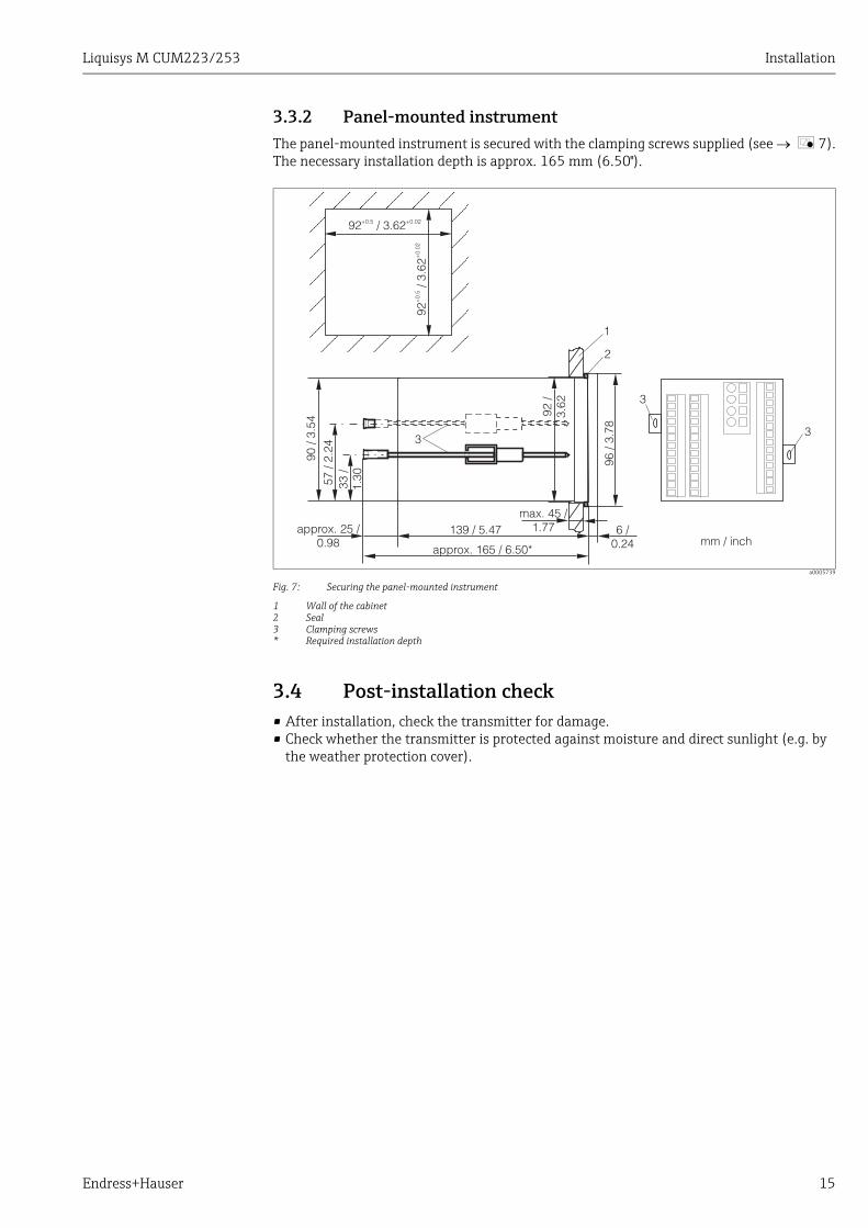
3.3.2 Panel-mounted instrumentThe panel-mounted instrument is secured with the clamping screws supplied (see å 7).The necessary installation depth is approx. 165 mm (6.50").
a0005739
Fig. 7: Securing the panel-mounted instrument
1 Wall of the cabinet2 Seal3 Clamping screws* Required installation depth
3.4 Post-installation check• After installation, check the transmitter for damage.• Check whether the transmitter is protected against moisture and direct sunlight (e.g. by
the weather protection cover).
1
2
3
3
3
92 / 3.62+0.5 +0.02
92/ 3
.62
+0.
5+
0.02
90 /
3.54
57 /
2.24
33 /
1.30
approx. 25 /0.98
139 / 5.47max. 45 /
1.77 6 /0.24
96 /
3.78
92 /
3.62
approx. 165 / 6.50*mm / inch

Electrical connection Liquisys M CUM223/253
16 Endress+Hauser
4 Electrical connectionWARNING!
Device is energizedImproper connection can cause injury or death.‣ The electrical connection must only be carried out by a certified electrician.‣ Technical personnel must have read and understood the instructions in this manual and
must adhere to them.‣ Prior to beginning any wiring work, make sure voltage is not applied to any of the cables.
4.1 Wiring NOTICE
The device does not have a power switch‣ You must provide a protected circuit breaker in the vicinity of the device.‣ This must be a switch or a power-circuit breaker and you must label it as the circuit
breaker for the device.‣ At the supply point, the power supply for the 24 V versions must be isolated from
dangerous live cables by double or reinforced insulation.
Liquisys M CUM223/253 Electrical connection
Endress+Hauser 17
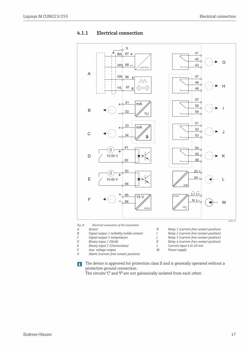
4.1.1 Electrical connection
The device is approved for protection class II and is generally operated without a protective ground connection.The circuits "C" and "F" are not galvanically isolated from each other.
a0003126
Fig. 8: Electrical connection of the transmitterABCDEFG
SensorSignal output 1 turbidity/solids contentSignal output 2 temperatureBinary input 1 (Hold)Binary input 2 (Chemoclean)Aux. voltage outputAlarm (current-free contact position)
HIJKLM
Relay 1 (current-free contact position)Relay 2 (current-free contact position)Relay 3 (current-free contact position)Relay 4 (current-free contact position)Current input 4 to 20 mAPower supply
47
48
49
57
58
59
41
42
43
15 V85
86
10-50 V
81
93
82
94
10-50 V
TU
mA31
32
mA33
34
51
52
53
54
55
56
97
88
87
96
S
GN
WH
BN
YE
23 +
24 -
mA
L+
L–N
L1~ =
A
B
C
D
E
F
G
H
I
J
K
L
M
A
B
Electrical connection Liquisys M CUM223/253
18 Endress+Hauser
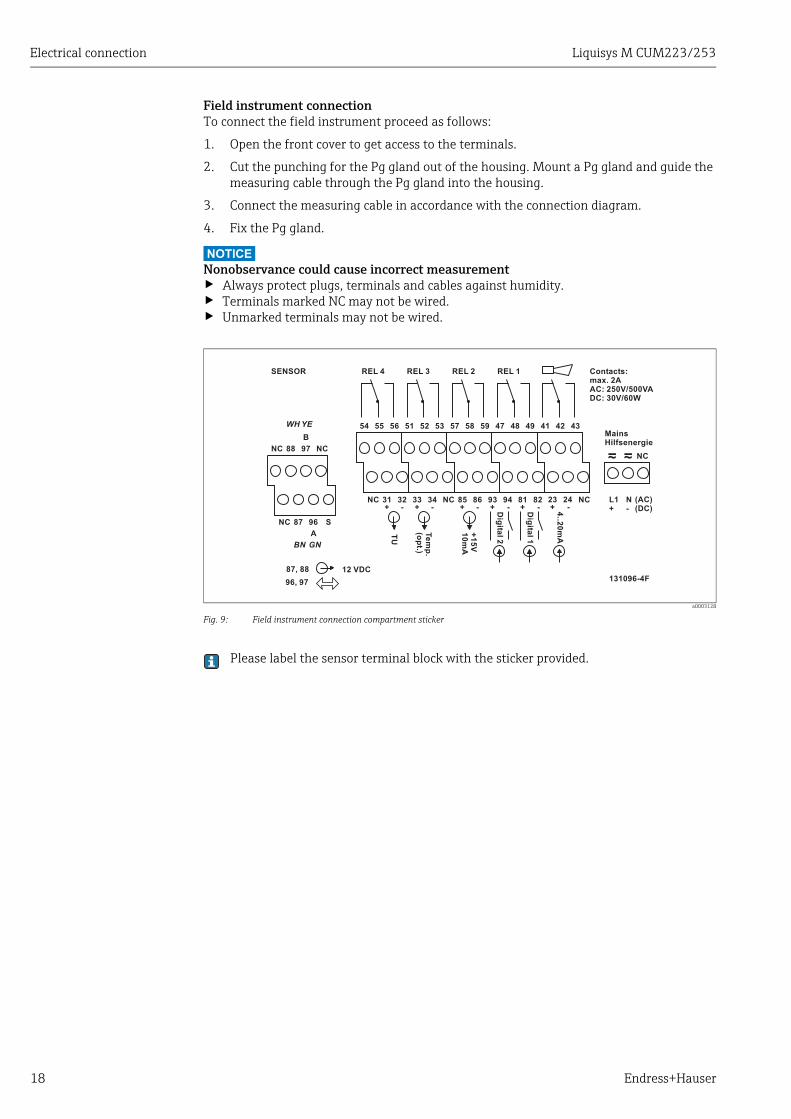
Field instrument connectionTo connect the field instrument proceed as follows:
1. Open the front cover to get access to the terminals.
2. Cut the punching for the Pg gland out of the housing. Mount a Pg gland and guide the measuring cable through the Pg gland into the housing.
3. Connect the measuring cable in accordance with the connection diagram.
4. Fix the Pg gland.
NOTICENonobservance could cause incorrect measurement‣ Always protect plugs, terminals and cables against humidity.‣ Terminals marked NC may not be wired.‣ Unmarked terminals may not be wired.
a0003128
Fig. 9: Field instrument connection compartment sticker
Please label the sensor terminal block with the sticker provided.
42
+++++ -----
434154 55 56
NC
96
88
87
31
NC 97 NC
32
NC
3433
S
B
NC 938685 94 81 82 NC
51 52 53 57 58 59 47 48 49
TU
Te
mp
.(o
pt.)
+1
5V
10
mAGNBN
YEWH
A
REL 4SENSOR REL 3 REL 2 REL 1
131096-4F
Dig
ital2
Dig
ital1
87, 88 12 VDC
96, 97
NC
MainsHilfsenergie
L1+
N-
(AC)(DC)
Contacts:max. 2AAC: 250V/500VADC: 30V/60W
+ -23 24
4..2
0m
A
Liquisys M CUM223/253 Electrical connection
Endress+Hauser 19
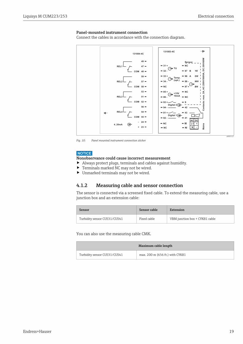
Panel-mounted instrument connectionConnect the cables in accordance with the connection diagram.
a0003127
Fig. 10: Panel mounted instrument connection sticker
NOTICENonobservance could cause incorrect measurement‣ Always protect plugs, terminals and cables against humidity.‣ Terminals marked NC may not be wired.‣ Unmarked terminals may not be wired.
4.1.2 Measuring cable and sensor connectionThe sensor is connected via a screened fixed cable. To extend the measuring cable, use a junction box and an extension cable:
You can also use the measuring cable CMK.
31 +
32 -
33 +
97
NC
Sensor
NC
NC
NC
B
A
YE
GN
WH
BN
34 -
85 +
86 -
93 + S
94 - 42
81 + 43
82 - 41
TU
Temp.(opt.)
+15V10mA
Digital 2
Digital 1
96
88 -
87 +
NC
NC
131083-4C
Ma
ins
Co
nta
cts
:m
ax
.2
A,A
C:2
50
V/5
00
VA
,D
C:3
0V
/60
W
L1 +
AC DC
N -
REL1
REL2
REL3
REL4
4..20mA
24
23
49
COM
COM
COM
COM
-
+
59
54
55
56
52
51
53
58
57
48
47
131084-4C
Sensor Sensor cable Extension
Turbidity sensor CUS31/CUS41 Fixed cable VBM junction box + CYK81 cable
Maximum cable length
Turbidity sensor CUS31/CUS41 max. 200 m (656 ft.) with CYK81
Electrical connection Liquisys M CUM223/253
20 Endress+Hauser
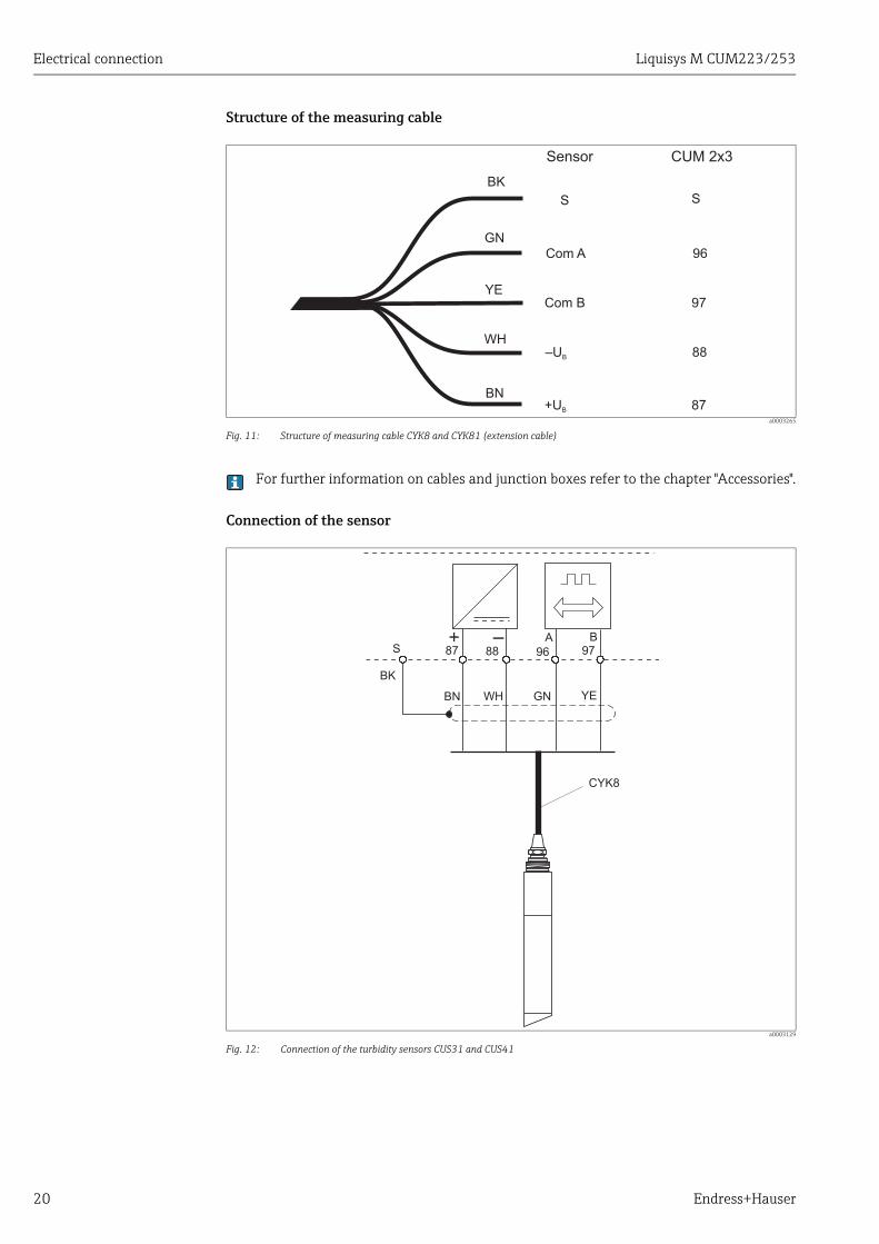
Structure of the measuring cable
a0003265
Fig. 11: Structure of measuring cable CYK8 and CYK81 (extension cable)
For further information on cables and junction boxes refer to the chapter "Accessories".
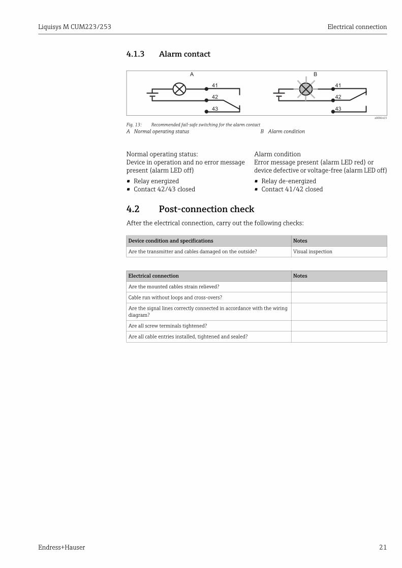
Connection of the sensor
a0003129
Fig. 12: Connection of the turbidity sensors CUS31 and CUS41
GN
YE
WH
BN
Com A
Com B
–UB
+UB
Sensor CUM 2x3
S
96
97
88
87
S
BK
CYK8
S 87 88 96 97
BN WH GN YE
A B
BK
Liquisys M CUM223/253 Electrical connection
Endress+Hauser 21
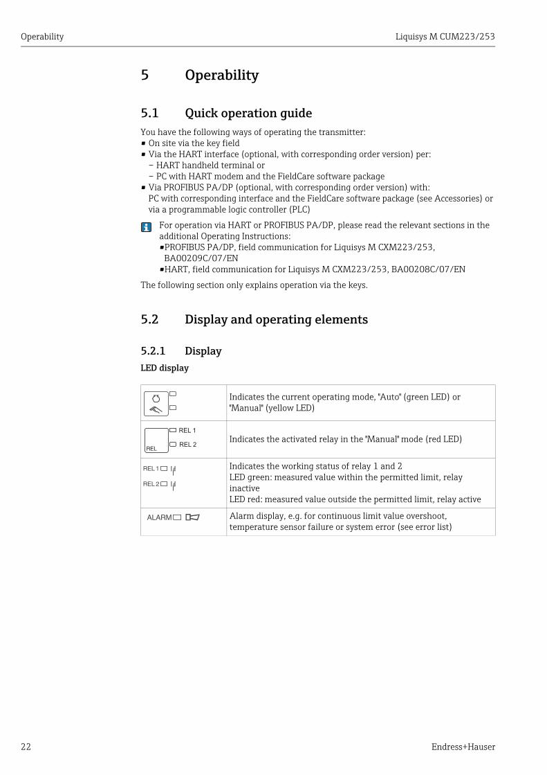
4.1.3 Alarm contact
4.2 Post-connection checkAfter the electrical connection, carry out the following checks:
a0006415
Fig. 13: Recommended fail-safe switching for the alarm contactA Normal operating status B Alarm condition
Normal operating status:Device in operation and no error message present (alarm LED off)
• Relay energized• Contact 42/43 closed
Alarm conditionError message present (alarm LED red) or device defective or voltage-free (alarm LED off)
• Relay de-energized• Contact 41/42 closed
Device condition and specifications Notes
Are the transmitter and cables damaged on the outside? Visual inspection
Electrical connection Notes
Are the mounted cables strain relieved?
Cable run without loops and cross-overs?
Are the signal lines correctly connected in accordance with the wiring diagram?
Are all screw terminals tightened?
Are all cable entries installed, tightened and sealed?
41
42
43
41
42
43
A B
Operability Liquisys M CUM223/253
22 Endress+Hauser
5 Operability
5.1 Quick operation guideYou have the following ways of operating the transmitter:• On site via the key field• Via the HART interface (optional, with corresponding order version) per:
– HART handheld terminal or– PC with HART modem and the FieldCare software package
• Via PROFIBUS PA/DP (optional, with corresponding order version) with:PC with corresponding interface and the FieldCare software package (see Accessories) or via a programmable logic controller (PLC)
For operation via HART or PROFIBUS PA/DP, please read the relevant sections in the additional Operating Instructions:•PROFIBUS PA/DP, field communication for Liquisys M CXM223/253,
BA00209C/07/EN•HART, field communication for Liquisys M CXM223/253, BA00208C/07/EN
The following section only explains operation via the keys.
5.2 Display and operating elements
5.2.1 DisplayLED display
Indicates the current operating mode, "Auto" (green LED) or "Manual" (yellow LED)
Indicates the activated relay in the "Manual" mode (red LED)
Indicates the working status of relay 1 and 2LED green: measured value within the permitted limit, relay inactiveLED red: measured value outside the permitted limit, relay active
Alarm display, e.g. for continuous limit value overshoot, temperature sensor failure or system error (see error list)
REL 1
REL 2
Liquisys M CUM223/253 Operability
Endress+Hauser 23
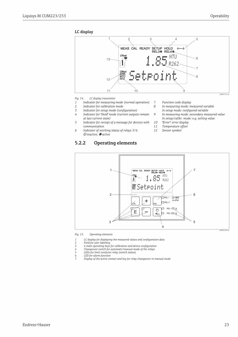
LC display
5.2.2 Operating elements
a0003130-en
Fig. 15: Operating elements
1 LC display for displaying the measured values and configuration data2 Field for user labelling3 4 main operating keys for calibration and device configuration4 Changeover switch for automatic/manual mode of the relays5 LEDs for limit contactor relay (switch status)6 LED for alarm function7 Display of the active contact and key for relay changeover in manual mode
a0003172-en
Fig. 14: LC display transmitter1234
5
6
Indicator for measuring mode (normal operation)Indicator for calibration modeIndicator for setup mode (configuration)Indicator for "Hold" mode (current outputs remain at last current state)Indicator for receipt of a message for devices with communicationIndicator of working status of relays 3/4: d inactive, c active
78
9
101112
Function code displayIn measuring mode: measured variableIn setup mode: configured variableIn measuring mode: secondary measured valueIn setup/calibr. mode: e.g. setting value"Error": error displayTemperature offsetSensor symbol
85NTU
R262
1 2 3 4 5
6
7
8
91011
12
13
1
Setpoint
1.85NTU
R262
1
2
3
4
5
6
7
Setpoint
Operability Liquisys M CUM223/253
24 Endress+Hauser
5.2.3 Key assignment
CAL keyWhen you press the CAL key, the device first prompts you for the calibration access code:
• Code 22 for calibration• Code 0 or any other code for reading the last calibration data
Use the CAL key to accept the calibration data or to switch from field to field within the calibration menu.
ENTER keyWhen you press the ENTER key, the device first prompts you for the setup mode access code:
• Code 22 for setup and configuration• Code 0 or any other code for reading all configuration data.
The ENTER key has several functions:
• Calls up the Setup menu from the measuring mode.• Saves (confirms) data entered in the setup mode.• Moves on within function groups.
PLUS key and MINUS keyIn the setup mode, the PLUS and MINUS keys have the following functions:
• Selection of function groups.Press the MINUS key to select the function groups in the order given in the "System configuration" section.
• Configuration of parameters and numerical values• Operation of the relay in manual mode
In the measuring mode, you get the following sequence of functions by repeatedly pressing the PLUS key:
1. Temperature display in F
2. Temperature display hidden
3. Current input signal in %
4. Current input signal in mA
5. Measured value display in FNU or NTU (uncompensated value without reflection compensation offset and slope, referred to data set 1)
In the measuring mode, the following is displayed in sequence by repeatedly pressing the MINUS key:
1. Current errors are displayed in rotation (max. 10).
2. Once all the errors have been displayed, the standard measurement display appears. In the function group F, an alarm can be defined separately for each error code.
REL keyIn the manual mode, you can use the REL key to switch between the relay and the manual start of cleaning. In the automatic mode, you can use the REL key to read out the switch-on points (for limit contactor) or set points (for PID controller) assigned to the relay in question.Press the PLUS key to jump to the settings of the next relay. Use the REL key to get back to the display mode (automatic return after 30 s).
REL 1
REL 2
Liquisys M CUM223/253 Operability
Endress+Hauser 25
AUTO keyYou can use the AUTO key to switch between automatic mode and manual mode.
Escape functionIf you press the PLUS and MINUS key simultaneously, you return to the main menu or are taken to the end of calibration if calibrating. If you press the PLUS and MINUS key again, you return to the measuring mode.
Locking the keyboardPress the PLUS and ENTER key for at least 3 s to lock the keyboard against any unauthorized data entry. All the settings can continue to be read. The code prompt displays the code 9999.
Unlocking the keyboardPress the CAL and MINUS key for at least 3 s to unlock the keyboard.The code prompt displays the code 0.
Operability Liquisys M CUM223/253
26 Endress+Hauser
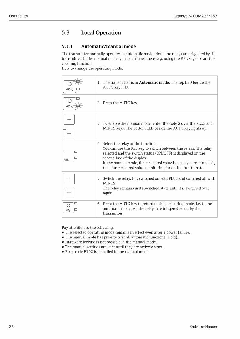
5.3 Local Operation
5.3.1 Automatic/manual modeThe transmitter normally operates in automatic mode. Here, the relays are triggered by the transmitter. In the manual mode, you can trigger the relays using the REL key or start the cleaning function. How to change the operating mode:
Pay attention to the following:• The selected operating mode remains in effect even after a power failure.• The manual mode has priority over all automatic functions (Hold).• Hardware locking is not possible in the manual mode.• The manual settings are kept until they are actively reset.• Error code E102 is signalled in the manual mode.
1. The transmitter is in Automatic mode. The top LED beside the AUTO key is lit.
2. Press the AUTO key.
3. To enable the manual mode, enter the code 22 via the PLUS and MINUS keys. The bottom LED beside the AUTO key lights up.
4. Select the relay or the function. You can use the REL key to switch between the relays. The relay selected and the switch status (ON/OFF) is displayed on the second line of the display.In the manual mode, the measured value is displayed continuously (e.g. for measured value monitoring for dosing functions).
5. Switch the relay. It is switched on with PLUS and switched off with MINUS.The relay remains in its switched state until it is switched over again.
6. Press the AUTO key to return to the measuring mode, i.e. to the automatic mode. All the relays are triggered again by the transmitter.
Liquisys M CUM223/253 Operability
Endress+Hauser 27
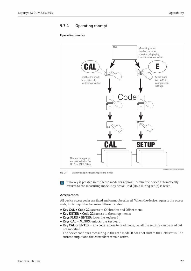
5.3.2 Operating concept
Operating modes
C07-CxM2x3xx-19-06-00-en-001.eps
Fig. 16: Description of the possible operating modes
If no key is pressed in the setup mode for approx. 15 min, the device automatically returns to the measuring mode. Any active Hold (Hold during setup) is reset.
Access codes
All device access codes are fixed and cannot be altered. When the device requests the access code, it distinguishes between different codes.
• Key CAL + Code 22: access to Calibration and Offset menu• Key ENTER + Code 22: access to the setup menus • Keys PLUS + ENTER: locks the keyboard• Keys CAL + MINUS: unlocks the keyboard• Key CAL or ENTER + any code: access to read mode, i.e. all the settings can be read but
not modified.The device continues measuring in the read mode. It does not shift to the Hold status. The current output and the controllers remain active.
Code
Measuring mode:standard mode ofoperation, displayingcurrent measured values
Setup modeaccess to allconfigurationsettings
Calibration mode:execution ofcalibration routine
The function groupsare selected with thePLUS or MINUS key.
Operability Liquisys M CUM223/253
28 Endress+Hauser
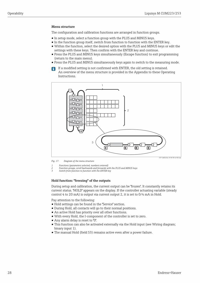
Menu structure
The configuration and calibration functions are arranged in function groups.
• In setup mode, select a function group with the PLUS and MINUS keys.• In the function group itself, switch from function to function with the ENTER key.• Within the function, select the desired option with the PLUS and MINUS keys or edit the
settings with these keys. Then confirm with the ENTER key and continue. • Press the PLUS and MINUS keys simultaneously (Escape function) to exit programming
(return to the main menu).• Press the PLUS and MINUS simultaneously keys again to switch to the measuring mode.
If a modified setting is not confirmed with ENTER, the old setting is retained.An overview of the menu structure is provided in the Appendix to these Operating Instructions.
C07-CxM2x3xx-19-06-00-xx-002.eps
Fig. 17: Diagram of the menu structure
1 Functions (parameters selected, numbers entered)2 Function groups, scroll backwards and forwards with the PLUS and MINUS keys3 Switch from function to function with the ENTER key
Hold function: "freezing" of the outputs
During setup and calibration, the current output can be "frozen". It constantly retains its current status. "HOLD" appears on the display. If the controller actuating variable (steady control 4 to 20 mA) is output via current output 2, it is set to 0/4 mA in Hold.
Pay attention to the following:• Hold settings can be found in the "Service" section.• During Hold, all contacts will go to their normal positions.• An active Hold has priority over all other functions.• With every Hold, the I-component of the controller is set to zero.• Any alarm delay is reset to "0".• This function can also be activated externally via the Hold input (see Wiring diagram;
binary input 1).• The manual Hold (field S3) remains active even after a power failure.
EE E E
-
1
2
3
E EE EEE EEE
Liquisys M CUM223/253 Commissioning
Endress+Hauser 29
6 Commissioning
6.1 Function checkWARNING!
Incorrect connection, incorrect supply voltageSafety risks for staff and incorrect operation of the device‣ Check that all connections have been established correctly in accordance with the wiring
diagram.‣ Make sure that the supply voltage matches the voltage indicated on the nameplate.
6.2 Switching onFamiliarize yourself with the operation of the transmitter before it is first switched on. Please refer in particular to the "Safety instructions" and "Operation" sections.After power-up, the device performs a self-test and then goes to the measuring mode.Now calibrate the sensor in accordance with the instructions in the "Calibration" section.Then perform the first configuration in accordance with the instructions in the "Quick start-up" section. The values set by the user are kept even in the event of a power failure.The following function groups are available in the transmitter (the groups only available in the Plus Package are marked accordingly in the functional description):
Setup mode• SETUP 1 (A)• SETUP 2 (B)• CURRENT INPUT (Z)• CURRENT OUTPUT (O)• ALARM (F)• CHECK (P)• RELAY (R)• CONCENTRATION MEASUREMENT (K)• SERVICE (S)• E+H SERVICE (E)• INTERFACE (I)
Calibration and offset mode• CALIBRATION (C)• OFFSET (V)• SLOPE (N)
A detailed explanation of the function groups available in the transmitter can be found in the "System configuration" section.
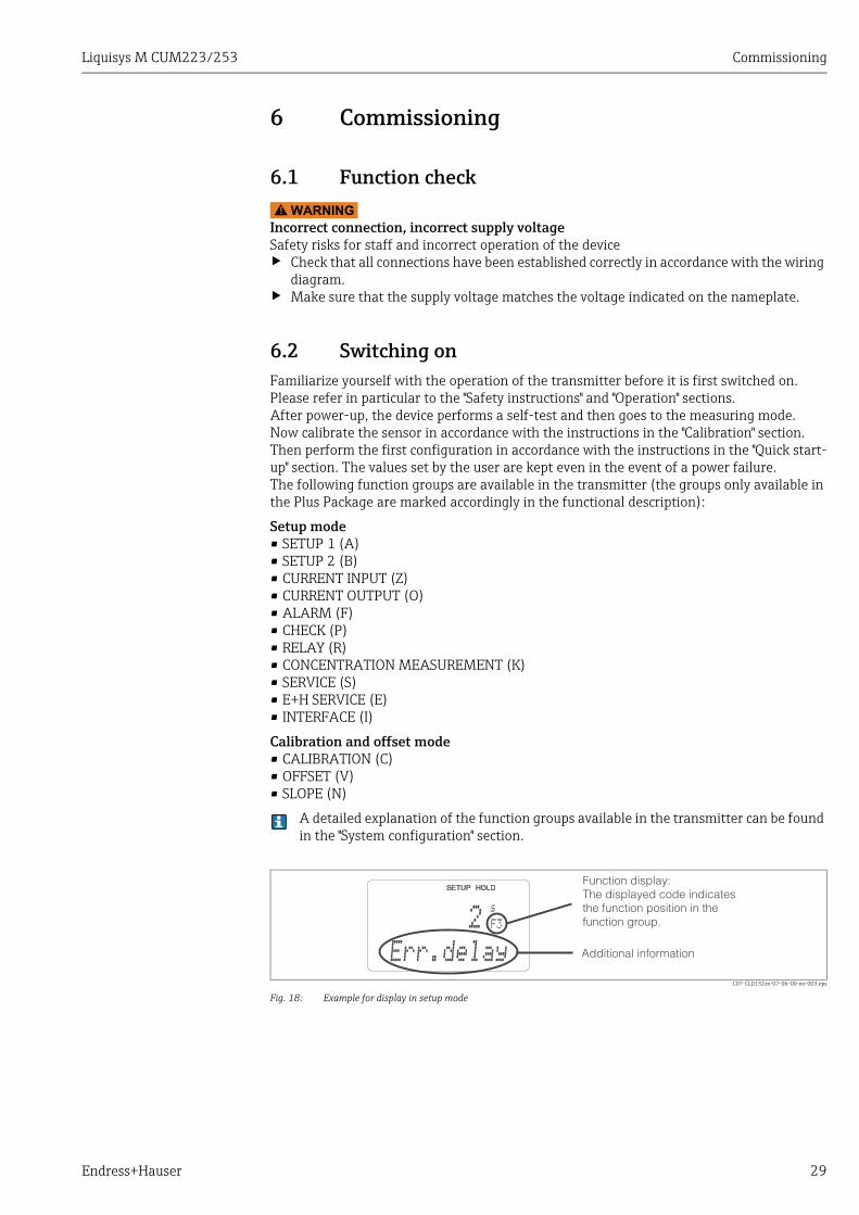
C07-CLD132xx-07-06-00-en-003.eps
Fig. 18: Example for display in setup mode
s
F3
Err.delay
Function display:The displayed code indicatesthe function position in thefunction group.
Additional information
2
Commissioning Liquisys M CUM223/253
30 Endress+Hauser
Factory settings
The first time it is switched on, the device has the factory setting for all functions. The table below provides an overview of the most important settings.All other factory settings can be found in the description of the individual function groups in the "System configuration" section (the factory setting is highlighted in bold).
* For corresponding version
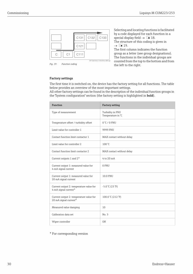
C07-CLD132xx-13-06-00-xx-005.eps
Fig. 19: Function coding
Selecting and locating functions is facilitated by a code displayed for each function in a special display field å 18. The structure of this coding is given in å 19.The first column indicates the function group as a letter (see group designations). The functions in the individual groups are counted from the top to the bottom and from the left to the right.
Function Factory setting
Type of measurement Turbidity in FNUTemperature in °C
Temperature offset / turbidity offset 0 °C / 0 FNU
Limit value for controller 1 9999 FNU
Contact function limit contactor 1 MAX contact without delay
Limit value for controller 2 100 °C
Contact function limit contactor 2 MAX contact without delay
Current outputs 1 and 2* 4 to 20 mA
Current output 1: measured value for 4 mA signal current
0 FNU
Current output 1: measured value for 20 mA signal current
10.0 FNU
Current output 2: temperature value for4 mA signal current*
-5.0 °C (23 °F)
Current output 2: temperature value for 20 mA signal current*
100.0 °C (212 °F)
Measured value damping 10
Calibration data set No. 3
Wiper controller Off
C C1 C111
C121
C131 C132 C133
Liquisys M CUM223/253 Commissioning
Endress+Hauser 31
6.3 Quick start-upAfter power-up, you must make some settings to configure the most important functions of the transmitter which are required for correct measurement. The following section gives an example of this.
User input Setting range(Factory settings, bold)
Display
1. Press the ENTER key.
2. Enter the code 22 to edit the setup. Press ENTER.
3. Press MINUS until you get to the "Service" function group.
4. Press ENTER to be able to make your settings.
5. In S1, select your language, e.g. "ENG" for English.Press ENTER to confirm.
ENG = EnglishGER = GermanFRA = FrenchITA = ItalianNEL = DutchESP = Spanish
6. Press PLUS and MINUS simultaneously to exit the "Service" function group.
7. Press MINUS until you get to the "Setup 1" function group.
8. Press ENTER to be able to make your settings for "Setup 1".
9. In A1, select the desired mode of operation, e.g. "FNU".Press ENTER to confirm.
FNUNTU ppm mg/lg/l%spec.
10. A4 displays the sensor type.Press ENTER.
CUS31CUS41
11. In A5, enter measured value damping. Measured value damping causes averaging over the specified number of individual measured values. This is used for example, to stabilize the display if the measurement is unstable. Enter "1" if no damping is required.Press ENTER to confirm.The display returns to "Setup 1"
101 to 60
12. Press MINUS to go to the "Setup 2" function group.
13. Press ENTER to edit "Setup 2".
S
SERVICE
S1
Language
ENG
A
SETUP 1
A1FNU
Oper.Mode
A4CUS31
sensor
A5
Damping
1
B
SETUP 2
Commissioning Liquisys M CUM223/253
32 Endress+Hauser
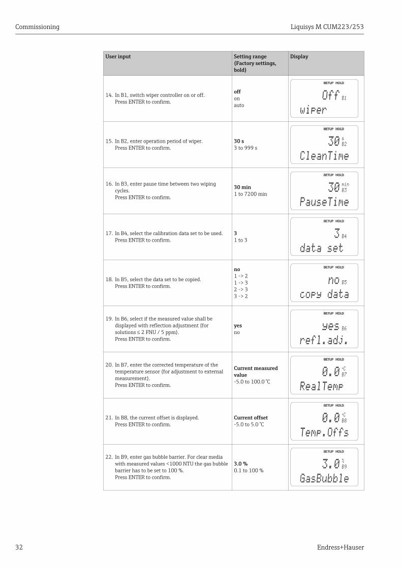
14. In B1, switch wiper controller on or off.Press ENTER to confirm.
offonauto
15. In B2, enter operation period of wiper.Press ENTER to confirm.
30 s3 to 999 s
16. In B3, enter pause time between two wiping cycles.Press ENTER to confirm.
30 min1 to 7200 min
17. In B4, select the calibration data set to be used.Press ENTER to confirm.
31 to 3
18. In B5, select the data set to be copied.Press ENTER to confirm.
no1 -> 21 -> 32 -> 33 -> 2
19. In B6, select if the measured value shall be displayed with reflection adjustment (for solutions 2 FNU / 5 ppm).Press ENTER to confirm.
yesno
20. In B7, enter the corrected temperature of the temperature sensor (for adjustment to external measurement).Press ENTER to confirm.
Current measured value-5.0 to 100.0 °C
21. In B8, the current offset is displayed.Press ENTER to confirm.
Current offset-5.0 to 5.0 °C
22. In B9, enter gas bubble barrier. For clear media with measured values <1000 NTU the gas bubble barrier has to be set to 100 %.Press ENTER to confirm.
3.0 %0.1 to 100 %
User input Setting range(Factory settings, bold)
Display
B1Off
wiper
B2
s
30
CleanTime
B3
min
30
PauseTime
B43
data set
B5no
copy data
B6yes
refl.adj.
B7
°C
0.0
RealTemp
B8
°C
0.0
Temp.Offs
B9
%
3.0
GasBubble
Liquisys M CUM223/253 Commissioning
Endress+Hauser 33
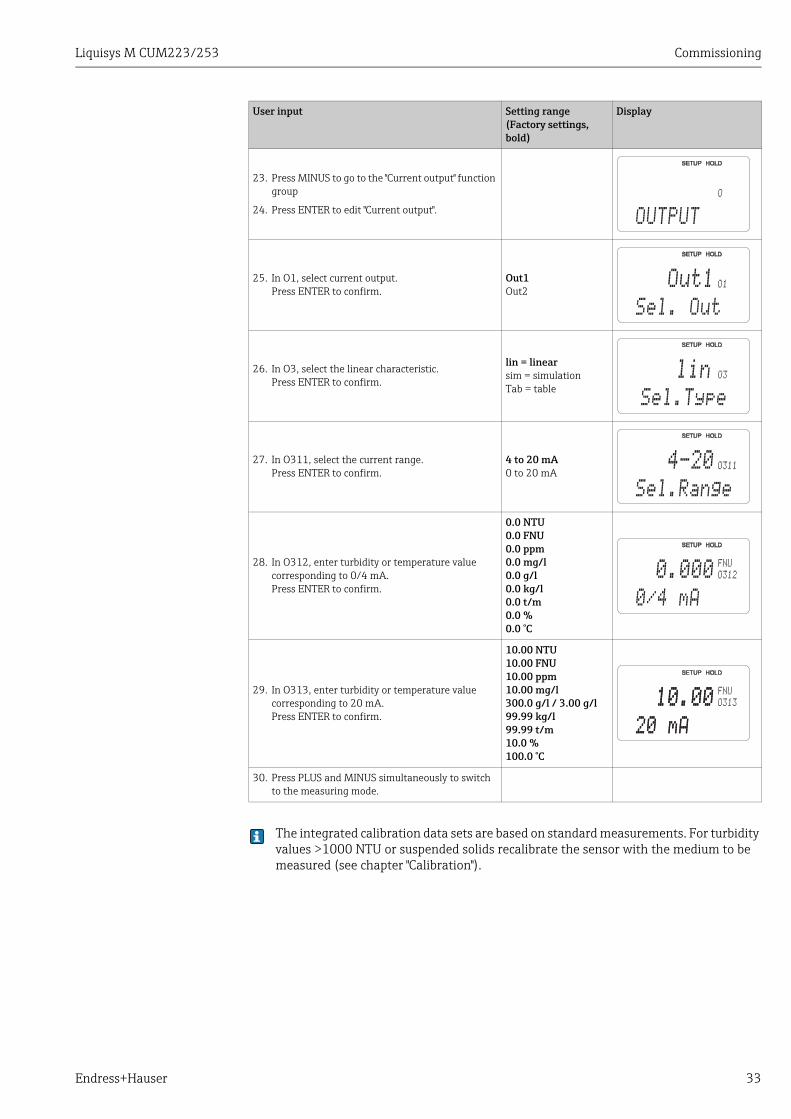
The integrated calibration data sets are based on standard measurements. For turbidity values >1000 NTU or suspended solids recalibrate the sensor with the medium to be measured (see chapter "Calibration").
23. Press MINUS to go to the "Current output" function group
24. Press ENTER to edit "Current output".
25. In O1, select current output.Press ENTER to confirm.
Out1Out2
26. In O3, select the linear characteristic.Press ENTER to confirm.
lin = linearsim = simulationTab = table
27. In O311, select the current range.Press ENTER to confirm.
4 to 20 mA0 to 20 mA
28. In O312, enter turbidity or temperature value corresponding to 0/4 mA.Press ENTER to confirm.
0.0 NTU0.0 FNU0.0 ppm0.0 mg/l0.0 g/l0.0 kg/l0.0 t/m0.0 %0.0 °C
29. In O313, enter turbidity or temperature value corresponding to 20 mA.Press ENTER to confirm.
10.00 NTU10.00 FNU10.00 ppm10.00 mg/l300.0 g/l / 3.00 g/l99.99 kg/l99.99 t/m10.0 %100.0 °C
30. Press PLUS and MINUS simultaneously to switch to the measuring mode.
User input Setting range(Factory settings, bold)
Display
O
OUTPUT
O1
Sel. Out
Out1
lin O3
Sel.Type
O311
Sel.Range
4-20
O312
FNU
0/4 mA
0.000
O313
20 mA
10.00FNU
20 mA
10.00
Commissioning Liquisys M CUM223/253
34 Endress+Hauser
6.4 System configuration
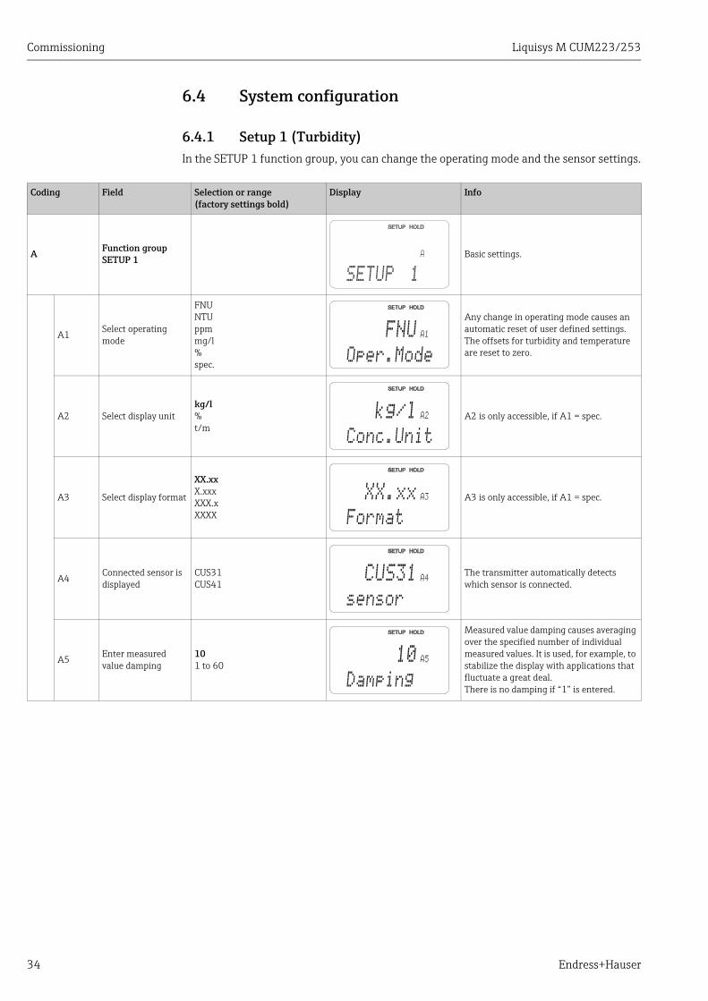
6.4.1 Setup 1 (Turbidity)In the SETUP 1 function group, you can change the operating mode and the sensor settings.
Coding Field Selection or range(factory settings bold)
Display Info
A Function group SETUP 1 Basic settings.
A1 Select operating mode
FNUNTUppmmg/l%spec.
Any change in operating mode causes an automatic reset of user defined settings. The offsets for turbidity and temperature are reset to zero.
A2 Select display unitkg/l%t/m
A2 is only accessible, if A1 = spec.
A3 Select display format
XX.xxX.xxxXXX.xXXXX
A3 is only accessible, if A1 = spec.
A4Connected sensor is displayed
CUS31CUS41
The transmitter automatically detects which sensor is connected.
A5 Enter measured value damping
101 to 60
Measured value damping causes averaging over the specified number of individual measured values. It is used, for example, to stabilize the display with applications that fluctuate a great deal.There is no damping if “1” is entered.
A
SETUP 1
A1FNU
Oper.Mode
A2kg/l
Conc.Unit
A3XX.xx
Format
A4CUS31
sensor
A510
Damping
Liquisys M CUM223/253 Commissioning
Endress+Hauser 35
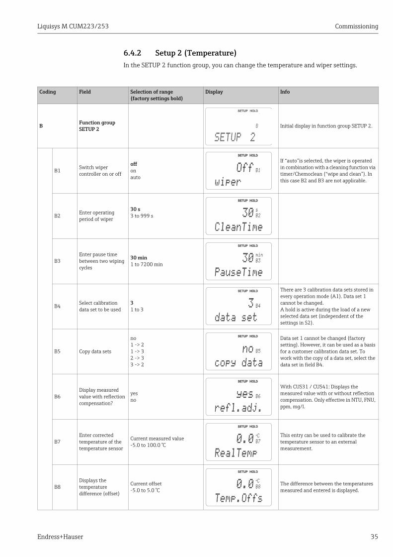
6.4.2 Setup 2 (Temperature)In the SETUP 2 function group, you can change the temperature and wiper settings.
Coding Field Selection of range(factory settings bold)
Display Info
B Function group SETUP 2 Initial display in function group SETUP 2.
B1 Switch wiper controller on or off
offonauto
If “auto”is selected, the wiper is operated in combination with a cleaning function via timer/Chemoclean (“wipe and clean”). In this case B2 and B3 are not applicable.
B2 Enter operating period of wiper
30 s3 to 999 s
B3Enter pause time between two wiping cycles
30 min1 to 7200 min
B4 Select calibration data set to be used
31 to 3
There are 3 calibration data sets stored in every operation mode (A1). Data set 1 cannot be changed.A hold is active during the load of a new selected data set (independent of the settings in S2).
B5 Copy data sets
no1 -> 21 -> 32 -> 33 -> 2
Data set 1 cannot be changed (factory setting). However, it can be used as a basis for a customer calibration data set. To work with the copy of a data set, select the data set in field B4.
B6Display measured value with reflection compensation?
yesno
With CUS31 / CUS41: Displays the measured value with or without reflection compensation. Only effective in NTU, FNU, ppm, mg/l.
B7Enter corrected temperature of the temperature sensor
Current measured value-5.0 to 100.0 °C
This entry can be used to calibrate the temperature sensor to an external measurement.
B8Displays the temperature difference (offset)
Current offset-5.0 to 5.0 °C
The difference between the temperatures measured and entered is displayed.
B
SETUP 2
B1Off
wiper
B2
s
30
CleanTime
B3
min
30
PauseTime
B43
data set
B5no
copy data
B6yes
refl.adj.
B7
°C
0.0
RealTemp
B8
°C
0.0
Temp.Offs

Commissioning Liquisys M CUM223/253
36 Endress+Hauser
B9 Enter gas bubble barrier
0.1 %0.1 to 100 °C
Compensates gas bubble formation, which may arise from small amounts of dissolved gas in the medium.0.1 % = no formation of gas bubbles.100 % = strong gas bubble formation.For clear media (measured value below 1000 NTU) always set the gas bubble barrier to 100 %.
Coding Field Selection of range(factory settings bold)
Display Info
B9
%
3.0
GasBubble
Liquisys M CUM223/253 Commissioning
Endress+Hauser 37
6.4.3 Current inputTo use the "Current input" function group, you need a relay board with current input which is not part of the basic version. With this function group you can monitor process parameters and use these for feedforward control. For this purpose, you must connect the current output of an external measured variable (e.g. flowmeter) to the 4 to 20 mA input of the transmitter. The following assignment applies:
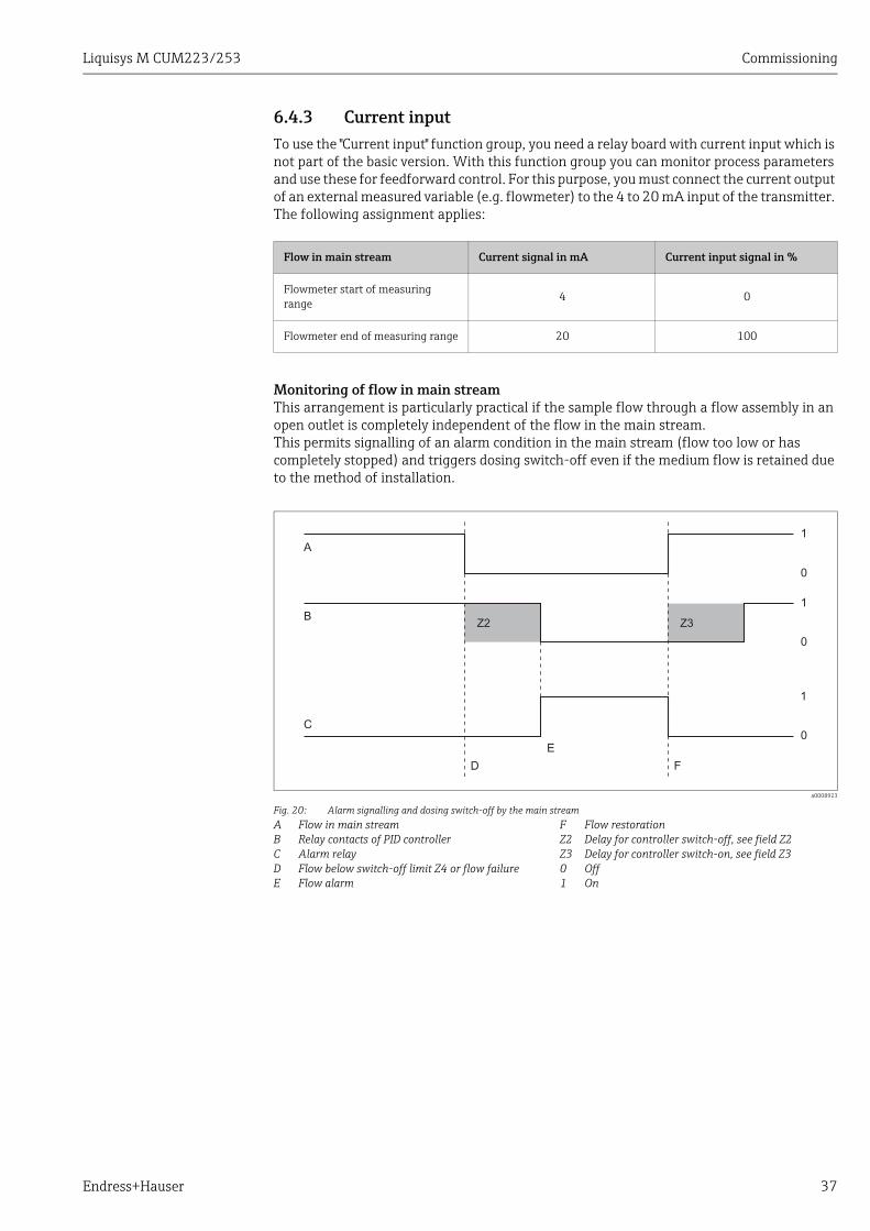
Monitoring of flow in main streamThis arrangement is particularly practical if the sample flow through a flow assembly in an open outlet is completely independent of the flow in the main stream.This permits signalling of an alarm condition in the main stream (flow too low or has completely stopped) and triggers dosing switch-off even if the medium flow is retained due to the method of installation.
Flow in main stream Current signal in mA Current input signal in %
Flowmeter start of measuring range 4 0
Flowmeter end of measuring range 20 100
a0008923
Fig. 20: Alarm signalling and dosing switch-off by the main streamABCDE
Flow in main streamRelay contacts of PID controllerAlarm relayFlow below switch-off limit Z4 or flow failureFlow alarm
FZ2Z301
Flow restorationDelay for controller switch-off, see field Z2Delay for controller switch-on, see field Z3OffOn
A
E
D F
C
B
1
0
0
0
1
1
Z2 Z3
Commissioning Liquisys M CUM223/253
38 Endress+Hauser
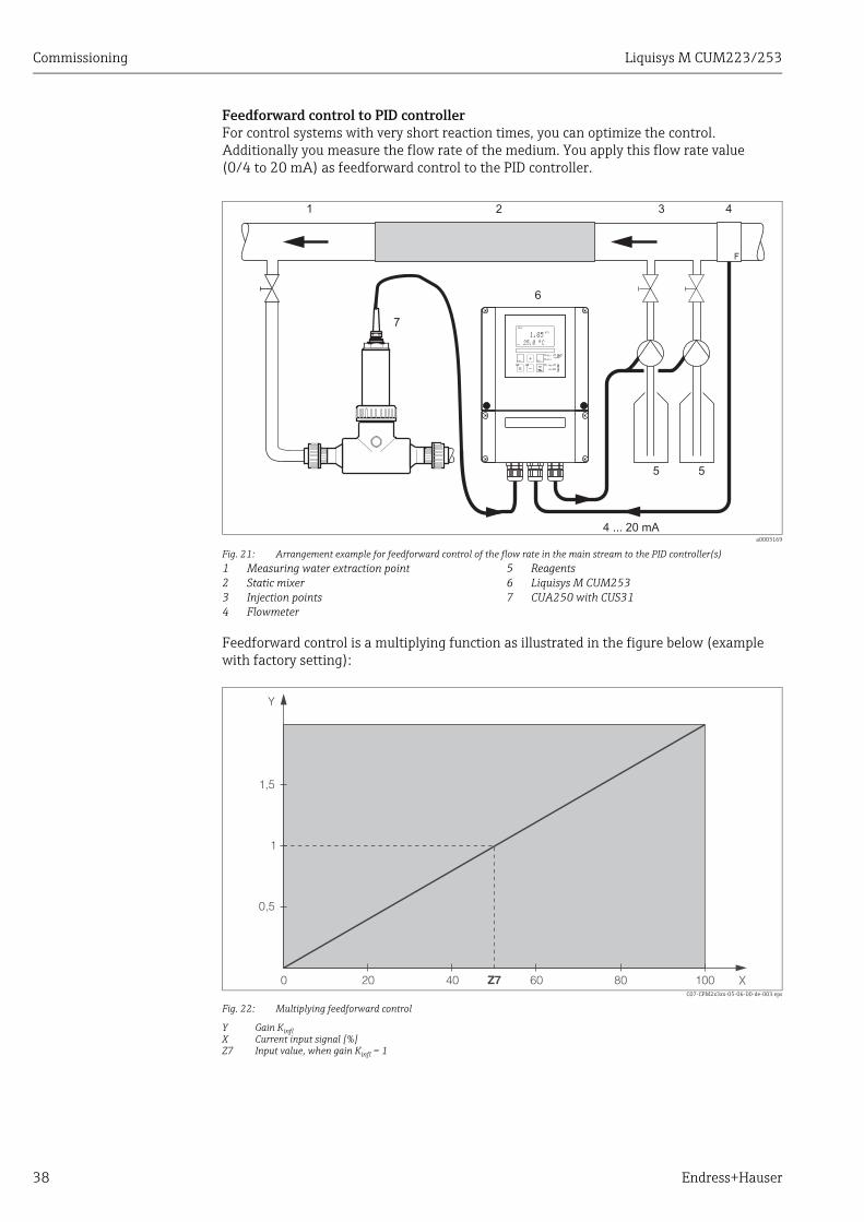
Feedforward control to PID controllerFor control systems with very short reaction times, you can optimize the control. Additionally you measure the flow rate of the medium. You apply this flow rate value (0/4 to 20 mA) as feedforward control to the PID controller.
Feedforward control is a multiplying function as illustrated in the figure below (example with factory setting):
C07-CPM2x3xx-05-06-00-de-003.eps
Fig. 22: Multiplying feedforward control
Y Gain KinflX Current input signal [%]Z7 Input value, when gain Kinfl = 1
a0003169
Fig. 21: Arrangement example for feedforward control of the flow rate in the main stream to the PID controller(s)1234
Measuring water extraction pointStatic mixerInjection pointsFlowmeter
567
ReagentsLiquisys M CUM253CUA250 with CUS31
CAL REL
REL1
REL1
ALARMREL2
REL2E
NTU
25.0 ¡C
1.85
F
4 ... 20 mA
1 2 3 4
55
6
7
1
0 20 40 60 80 100Z7
1,5
0,5
Y
X
Liquisys M CUM223/253 Commissioning
Endress+Hauser 39
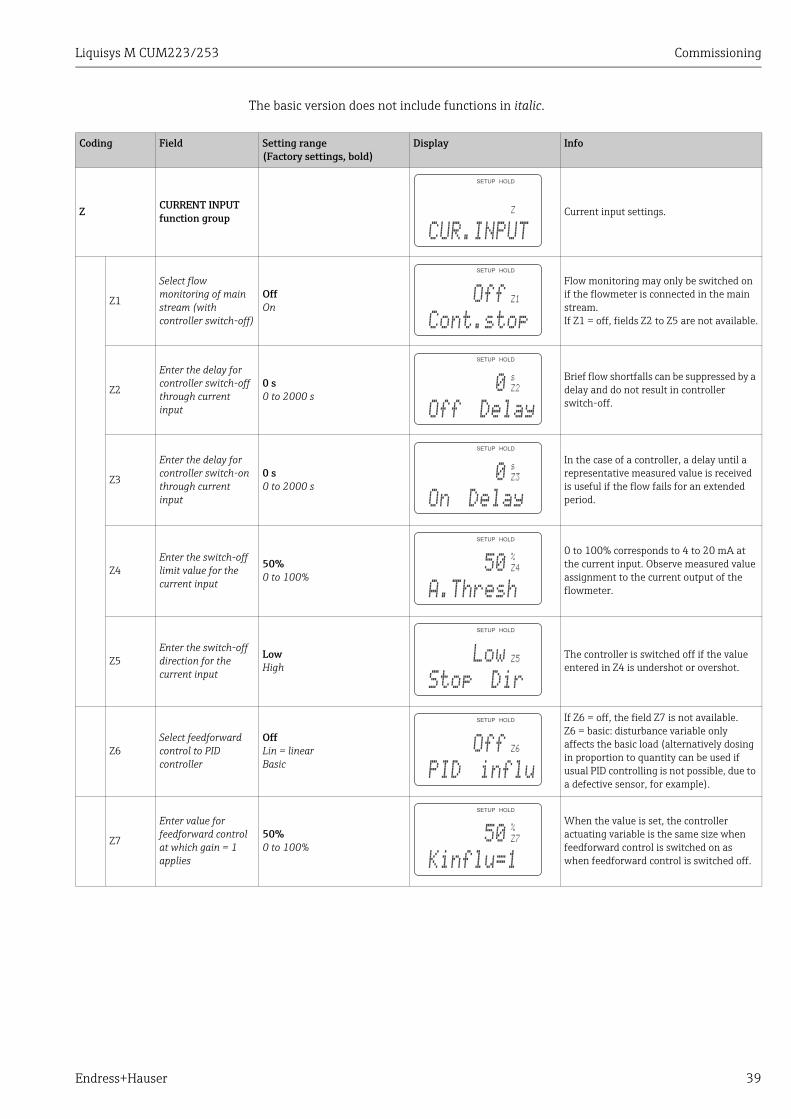
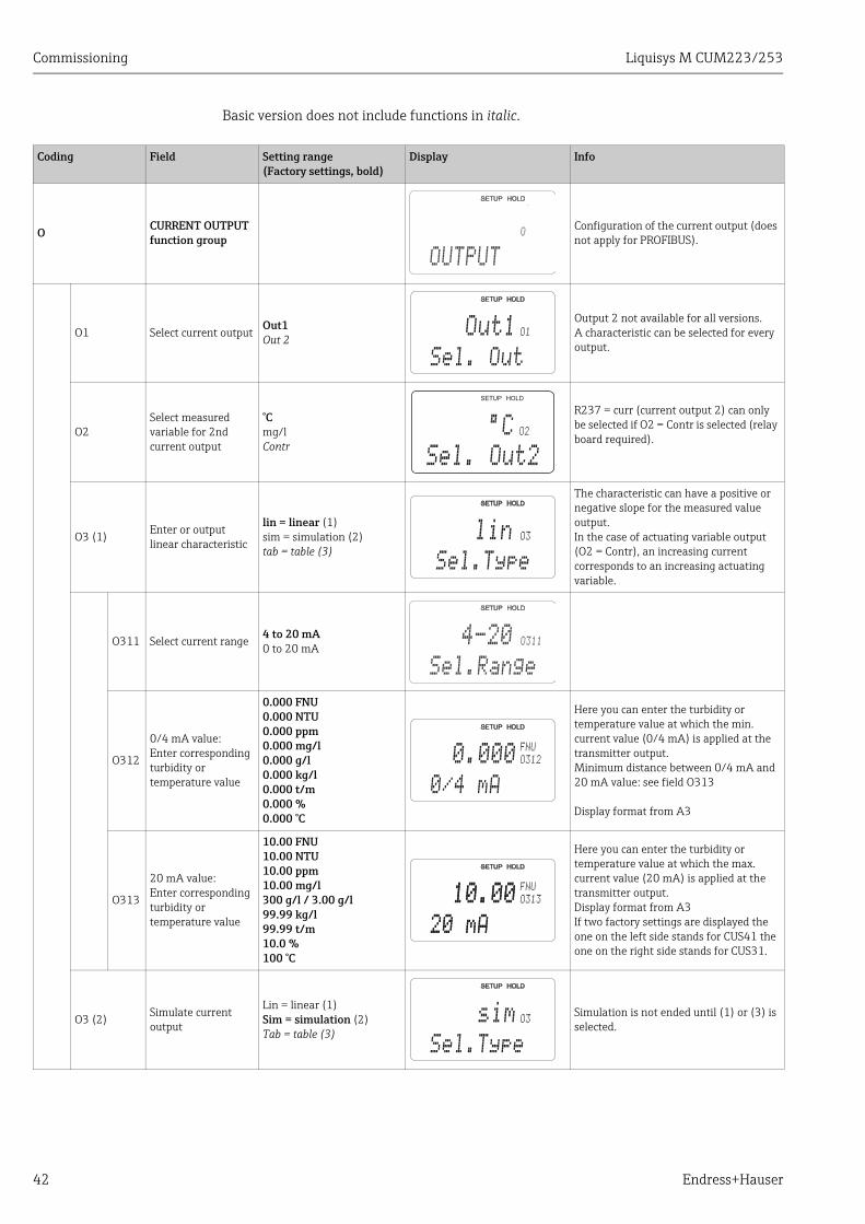
The basic version does not include functions in italic.
Coding Field Setting range(Factory settings, bold)
Display Info
Z CURRENT INPUT function group
Current input settings.
Z1
Select flow monitoring of main stream (with controller switch-off)
OffOn
Flow monitoring may only be switched on if the flowmeter is connected in the main stream.If Z1 = off, fields Z2 to Z5 are not available.
Z2
Enter the delay for controller switch-off through current input
0 s0 to 2000 s
Brief flow shortfalls can be suppressed by a delay and do not result in controller switch-off.
Z3
Enter the delay for controller switch-on through current input
0 s0 to 2000 s
In the case of a controller, a delay until a representative measured value is received is useful if the flow fails for an extended period.
Z4Enter the switch-off limit value for the current input
50%0 to 100%
0 to 100% corresponds to 4 to 20 mA at the current input. Observe measured value assignment to the current output of the flowmeter.
Z5Enter the switch-off direction for the current input
LowHigh
The controller is switched off if the value entered in Z4 is undershot or overshot.
Z6Select feedforward control to PID controller
OffLin = linearBasic
If Z6 = off, the field Z7 is not available.Z6 = basic: disturbance variable only affects the basic load (alternatively dosing in proportion to quantity can be used if usual PID controlling is not possible, due to a defective sensor, for example).
Z7
Enter value for feedforward control at which gain = 1 applies
50%0 to 100%
When the value is set, the controller actuating variable is the same size when feedforward control is switched on as when feedforward control is switched off.
Z
CUR.INPUT
Z1
Cont.stop
Off
Z2
s
Off Delay
0
Z3
s
On Delay
0
Z4
%
A.Thresh
50
Z5
Stop Dir
Low
Z6
PID influ
Off
Z7
%
Kinflu=1
50
Commissioning Liquisys M CUM223/253
40 Endress+Hauser
6.4.4 Current outputsUse the "Current output" function group to configure the individual outputs. You can enter either a linear characteristic (O3 (1)) or a user-defined current output characteristic in conjunction with the Plus Package (O3 (3)). Exception: if you have chosen a "continuous controller" for current output 2, you cannot enter a user-defined current output characteristic for this current output.In addition, you can simulate a current output value (O3 (2)) to check the current outputs.If a second current output is present, you can output the controller actuating variable in accordance with field R 237 via the current output.
a0003170
Fig. 23: User defined current output characteristic
The current output characteristic must be strictly monotonously increasing or strictly monotonously decreasing.The distance per mA between two table value pairs must be greater than:
• 0.005 FNU / NTU / ppm mg/l / %• 0.05 g/l• Temperature: 0.25 °C
The values for the sample characteristic ( å 23) are entered in the following table. The distance per mA can be calculated from signal / mA.
6000
3000
9000
0
0 4 8 12 16 20
DI [mA]I [mA]
DS
igna
l
FNU
Current output 1 Current output 2
Value pair Tu / °C Current[mA]
Distance per mA
Tu / °C Current[mA]
Distance per mA
1 0 4
2 3000 16 250
3 9000 20 1500
Liquisys M CUM223/253 Commissioning
Endress+Hauser 41
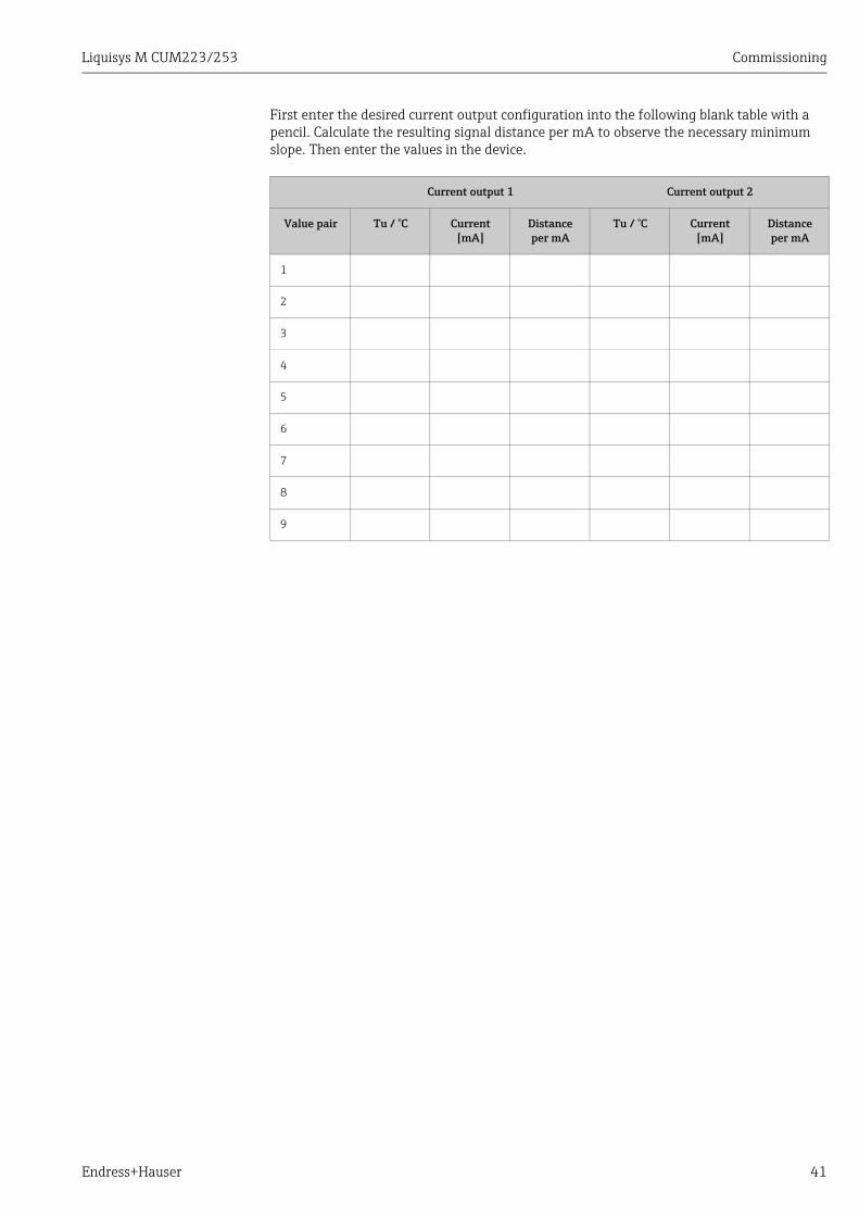
First enter the desired current output configuration into the following blank table with a pencil. Calculate the resulting signal distance per mA to observe the necessary minimum slope. Then enter the values in the device.
Current output 1 Current output 2
Value pair Tu / °C Current[mA]
Distance per mA
Tu / °C Current[mA]
Distance per mA
1
2
3
4
5
6
7
8
9
Commissioning Liquisys M CUM223/253
42 Endress+Hauser
Basic version does not include functions in italic.
Coding Field Setting range(Factory settings, bold)
Display Info
O CURRENT OUTPUT function group
Configuration of the current output (does not apply for PROFIBUS).
O1 Select current outputOut1Out 2
Output 2 not available for all versions.A characteristic can be selected for every output.
O2Select measured variable for 2nd current output
°Cmg/lContr
R237 = curr (current output 2) can only be selected if O2 = Contr is selected (relay board required).
O3 (1)Enter or output linear characteristic
lin = linear (1)sim = simulation (2)tab = table (3)
The characteristic can have a positive or negative slope for the measured value output.In the case of actuating variable output (O2 = Contr), an increasing current corresponds to an increasing actuating variable.
O311 Select current range 4 to 20 mA0 to 20 mA
O312
0/4 mA value:Enter corresponding turbidity or temperature value
0.000 FNU0.000 NTU0.000 ppm0.000 mg/l0.000 g/l0.000 kg/l0.000 t/m0.000 %0.000 °C
Here you can enter the turbidity or temperature value at which the min. current value (0/4 mA) is applied at the transmitter output.Minimum distance between 0/4 mA and 20 mA value: see field O313
Display format from A3
O313
20 mA value:Enter corresponding turbidity or temperature value
10.00 FNU10.00 NTU10.00 ppm10.00 mg/l300 g/l / 3.00 g/l99.99 kg/l99.99 t/m10.0 %100 °C
Here you can enter the turbidity or temperature value at which the max. current value (20 mA) is applied at the transmitter output.Display format from A3If two factory settings are displayed the one on the left side stands for CUS41 the one on the right side stands for CUS31.
O3 (2) Simulate current output
Lin = linear (1)Sim = simulation (2)Tab = table (3)
Simulation is not ended until (1) or (3) is selected.
O
OUTPUT
O1
Sel. Out
Out1
O2
Sel. Out2
¡C
lin O3
Sel.Type
O311
Sel.Range
4-20
O312
FNU
0/4 mA
0.000
O313
20 mA
10.00FNU
20 mA
10.00
O3sim
Sel.Type
Liquisys M CUM223/253 Commissioning
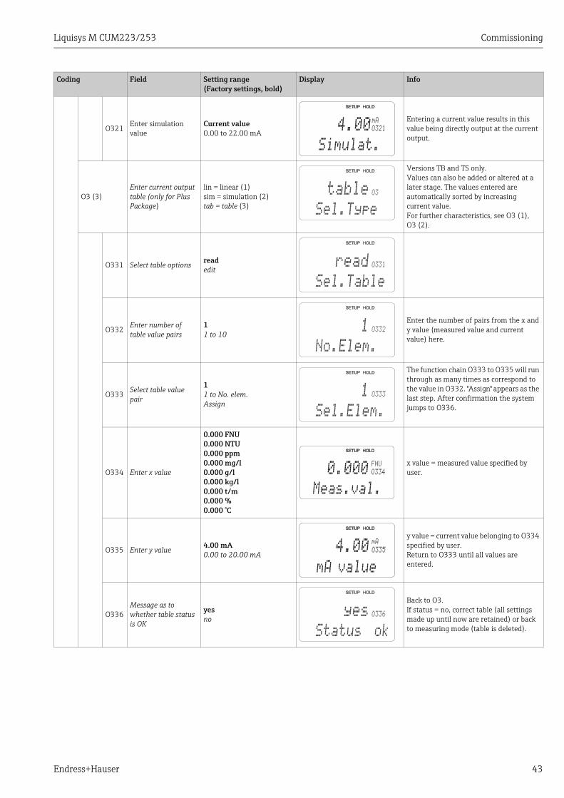
Endress+Hauser 43
O321Enter simulation value
Current value0.00 to 22.00 mA
Entering a current value results in this value being directly output at the current output.
O3 (3)Enter current output table (only for Plus Package)
lin = linear (1)sim = simulation (2)tab = table (3)
Versions TB and TS only.Values can also be added or altered at a later stage. The values entered are automatically sorted by increasing current value.For further characteristics, see O3 (1), O3 (2).
O331 Select table options readedit
O332Enter number of table value pairs
11 to 10
Enter the number of pairs from the x and y value (measured value and current value) here.
O333 Select table value pair
11 to No. elem.Assign
The function chain O333 to O335 will run through as many times as correspond to the value in O332. "Assign" appears as the last step. After confirmation the system jumps to O336.
O334 Enter x value
0.000 FNU0.000 NTU0.000 ppm0.000 mg/l0.000 g/l0.000 kg/l0.000 t/m0.000 %0.000 °C
x value = measured value specified by user.
O335 Enter y value 4.00 mA0.00 to 20.00 mA
y value = current value belonging to O334 specified by user.Return to O333 until all values are entered.
O336Message as to whether table status is OK
yesno
Back to O3.If status = no, correct table (all settings made up until now are retained) or back to measuring mode (table is deleted).
Coding Field Setting range(Factory settings, bold)
Display Info
O321
mA
Simulat.
4.00
O3
Sel.Type
table
O331
Sel.Table
read
O332
No.Elem.
1
O333
Sel.Elem.
1
O334
FNU
Meas.val.
0.000
O335
mA
mA value
4.00
O336
Status ok
yes
Commissioning Liquisys M CUM223/253
44 Endress+Hauser
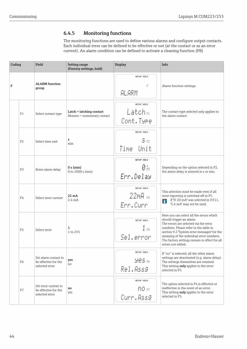
6.4.5 Monitoring functionsThe monitoring functions are used to define various alarms and configure output contacts. Each individual error can be defined to be effective or not (at the contact or as an error current). An alarm condition can be defined to activate a cleaning function (F8)
Coding Field Setting range(Factory settings, bold)
Display Info
F ALARM function group
Alarm function settings.
F1 Select contact typeLatch = latching contactMomen = momentary contact
The contact type selected only applies to the alarm contact.
F2 Select time unitsmin
F3 Enter alarm delay0 s (min)0 to 2000 s (min)
Depending on the option selected in F2, the alarm delay is entered in s or min.
F4 Select error current22 mA2.4 mA
This selection must be made even if all error reporting is switched off in F5.
If "0-20 mA" was selected in O311, "2.4 mA" may not be used.
F5 Select error 11 to 255
Here you can select all the errors which should trigger an alarm.The errors are selected via the error numbers. Please refer to the table in section 9.2 "System error messages" for the meaning of the individual error numbers. The factory settings remain in effect for all errors not edited.
F6Set alarm contact to be effective for the selected error
yesno
If “no” is selected, all the other alarm settings are deactivated (e.g. alarm delay). The settings themselves are retained.This setting only applies to the error selected in F5.
F7Set error current to be effective for the selected error
noyes
The option selected in F4 is effective or ineffective in the event of an error.This setting only applies to the error selected in F5.
F
ALARM
F1
Cont.Type
Latch
F2
Time Unit
s
F3
s
Err.Delay
0
F4
Err.Curr
22mA
F5
Sel.error
1
F6
Rel.Assg
yes
F7
Curr.Assg
no
Liquisys M CUM223/253 Commissioning
Endress+Hauser 45
Check
The CHECK function group is only available for devices with a Plus Package.In the CHECK function group, you can select different monitoring functions for the measurement.All monitoring functions are off by default. To adapt the Sensor Check System to the current application conditions, add and set the suitable functions.
Alarm threshold monitoring (fields P1 to P4)You can use this function to monitor the measured value for permissible upper and lower limits and trigger an alarm (E154, E155).
PCS alarm (Process Check System), (fields P5 to P8)AC (Alternating Check): The function AC (field P5) is used to check measuring signals for deviations. If the measuring signal does not change within an hour an alarm (E152) is triggered. The reason for such sensor behavior can be contamination, cable rupture or similar.CC (Controller Check): You can monitor the controller activity with the function CC. This function is mainly used for batch processes and single-sided limit switches. A malfunction of the controller is detected and reported thanks to freely adjustable monitoring times (E156 - E157).
a0006744
Fig. 24: PCS alarm (live check)
A Constant measuring signal = alarm triggered after PCS alarm time has elapsed
Any PCS alarm pending is automatically deleted as soon as the sensor signal changes.
F8 Automatic cleaning function start
noyes
This field is not available for certain errors, see "Trouble-shooting and fault elimination" section.
F9 Select return to menu or next error
next = next errorR
If R is selected, you return to F, if next is selected, you go to F5.
Coding Field Setting range(Factory settings, bold)
Display Info
F8
CleanTrig
no
F9
Select
next
A
t
Commissioning Liquisys M CUM223/253
46 Endress+Hauser
Monitoring functions at a glance
The function group "Check" is used to monitor the lower und upper limits of the measured value and to initiate alarms.
Functional description
Possible settings
Alarm event Application
Alarm threshold monitoring (P1 to P4)
– Freely adjustable lower alarm threshold (AT)
– Freely adjustable upper alarm threshold (AT)
off —
Applications with or without dosage control of chemicals
only lower AT Lower AT reached or dropped below
only upper AT Upper AT reached or exceeded
lower and upper AT
Lower AT reached or dropped below or upper AT reached or exceeded
Controller monitoring (CC: Controller Check, P5 to P8)
– Switch-on period monitoring
– Switch-off period monitoring
off — Applications with dosage control of chemicalson Set maximum period for
permanent switch-on or switch-off exceeded
Sensor activity monitoring (AC: Alternation Check, P5 to P8)
Monitoring for signal change
off — Applications with or without dosage control of chemicals
on No change within 1 hour
Liquisys M CUM223/253 Commissioning
Endress+Hauser 47
Basic version does not include functions in italic.
Coding Field Setting range(Factory settings, bold)
Display Info
P CHECK function group
Settings for sensor and process monitoring
P1 Select alarm threshold monitoring
OffLowHighLo+HiLow!High!Lo+Hi!
Alarm signalling optionally with or without simultaneous controller switch-off.XXXX = without controller switch-offXXXX! = with controller switch-off(Errors: E154, E155)
P2 Enter alarm delay 0 s (min)0 to 2000 s (min)
Depending on your selection in F2, you can enter the error delay in min or s. Only after this delay, a high or low limit violation causes an alarm as per field P3/P4.
P3 Enter lower alarm threshold
0.000 FNU0 to 9999 FNU
P4Enter upper alarm threshold
10.00 FNU0 to 9999 FNU
P5Select process monitoring(PCS alarm)
OffACCCAC+CCAC!CC!AC+CC!
AC = sensor activity check (E152)CC = controller check (E156, E157)XXXX = without controller switch-offXXXX! = with controller switch-off
P6
Enter maximum permissible duration for lower CC setpoint limit violation (field P8)
60 min0 to 2000 min Only when P5 = CC or AC+CC
P7
Enter maximum permissible duration for upper CC setpoint limit violation (field P8)
120 min0 to 2000 min Only when P5 = CC or AC+CC
P8Enter CC setpoint (for P6/P7)
1.000 FNU0 to 9999 FNU
Selected value is an absolute value. This function is mainly used for batch processes and single-sided limit switches.
P
CHECK
P1
A.Thresh
off
P2
min
Err.Delay
0
P3
FNU
LowAlarm
0.000
P4
FNU
HighAlarm
10.00
P5
ProcMonit
Off
P6
min
Tmax Low
60
P7
min
Tmax High
120
P8
FNU
Setpoint
1.000
Commissioning Liquisys M CUM223/253
48 Endress+Hauser
6.4.6 Relay contact configurationTo use the RELAY function group, you need a relay board which is not part of the basic version.
The following relay contacts can be selected and configured as desired (max. four contacts, depending on options installed):• Limit contactor for measured turbidity value: R2 (1)• Limit contactor for temperature: R2 (2)• PID controller: R2 (3)• Timer for cleaning function: R2 (4)• Chemoclean function: R2 (5)
Limit contactor for measured turbidity value and temperature
The transmitter has different ways of assigning a relay contact.Switch-on and switch-off points and pick-up and drop-out delays can be assigned to the limit contactor. In addition, you can configure an alarm threshold to output an error message and to start a cleaning function in conjunction with this.These functions can be used both for turbidity measurement and for temperature measurement.
Please refer to Fig. 25 for a clear illustration of the relay contact states.• When the measured values increase (maximum function), the relay contact is closed as of
t2 after the switch-on point (t1) has been overshot and the pick-up delay has elapsed (t2 - t1). The alarm contact switches if the alarm threshold (t3) is reached and the alarm delay (t4 - t3) has also elapsed.
• When the measured values decrease, the alarm contact is reset when the alarm threshold (t5) is undershot as is the relay contact (t7) after the drop-out delay (t7 - t6).
• If the pick-up and drop-out delays are set to 0 s, the switch-on and switch-off points are also switch points of the contacts.
Settings can also be made for a minimum function in the same way as for a maximum function.
C07-CxM2x3xx-05-06-00-xx-003.eps
Fig. 25: Illustration of the alarm and limit value functionsAB
Switch-on point > switch-off point: Max. functionSwitch-on point < switch-off point: Min. function
1234
Alarm thresholdSwitch-on pointSwitch-off pointContact ON
567
Alarm ONAlarm OFFContact OFF
t1
t1
t2
t2
t3
t3
t4
t4
t5
t5
t6
t6
t7
t7
t
t
B
1
23
32
1
4
56
7
4
56
7
A
Liquisys M CUM223/253 Commissioning
Endress+Hauser 49
P(ID) controller
You can define various controller functions for the transmitter. On the basis of the PID controller, P, PI, PD and PID controllers can be implemented. For an optimum control system, use the controller that best suits your application. Depending on the option selected in the R 237/R 266 field, the actuating signal can be output via relays or via current output 2 (if available).
• P controllerUsed for simple linear control purposes with small system deviations. Where major changes are to be controlled, overshooting may occur. In addition, a lasting control deviation is to be expected.
• PI controllerIs used for control systems where overshooting is to be avoided and no lasting control deviation should occur.
• PD controllerIs used for processes that require quick changes and where peaks are to be corrected.
• PID controllerIs used for processes where a P, PI or PD controller does not control sufficiently.
Configuration options of the PID controllerThe following configuration options are available for a PID controller:
• Change control gain Kp (P influence)• Set integral action time Tn (I influence)• Set derivative action time Tv (D influence)
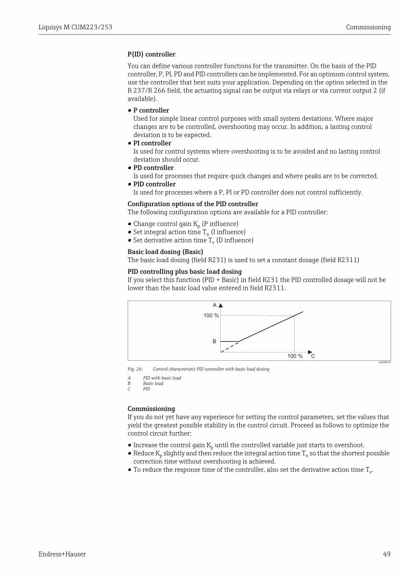
Basic load dosing (Basic)The basic load dosing (field R231) is used to set a constant dosage (field R2311)
PID controlling plus basic load dosingIf you select this function (PID + Basic) in field R231 the PID controlled dosage will not be lower than the basic load value entered in field R2311.
a0008940
Fig. 26: Control characteristic PID controller with basic load dosing
A PID with basic loadB Basic loadC PID
CommissioningIf you do not yet have any experience for setting the control parameters, set the values that yield the greatest possible stability in the control circuit. Proceed as follows to optimize the control circuit further:
• Increase the control gain Kp until the controlled variable just starts to overshoot.• Reduce Kp slightly and then reduce the integral action time Tn so that the shortest possible
correction time without overshooting is achieved.• To reduce the response time of the controller, also set the derivative action time Tv.
100 %
100 %
A
B
C
Commissioning Liquisys M CUM223/253
50 Endress+Hauser
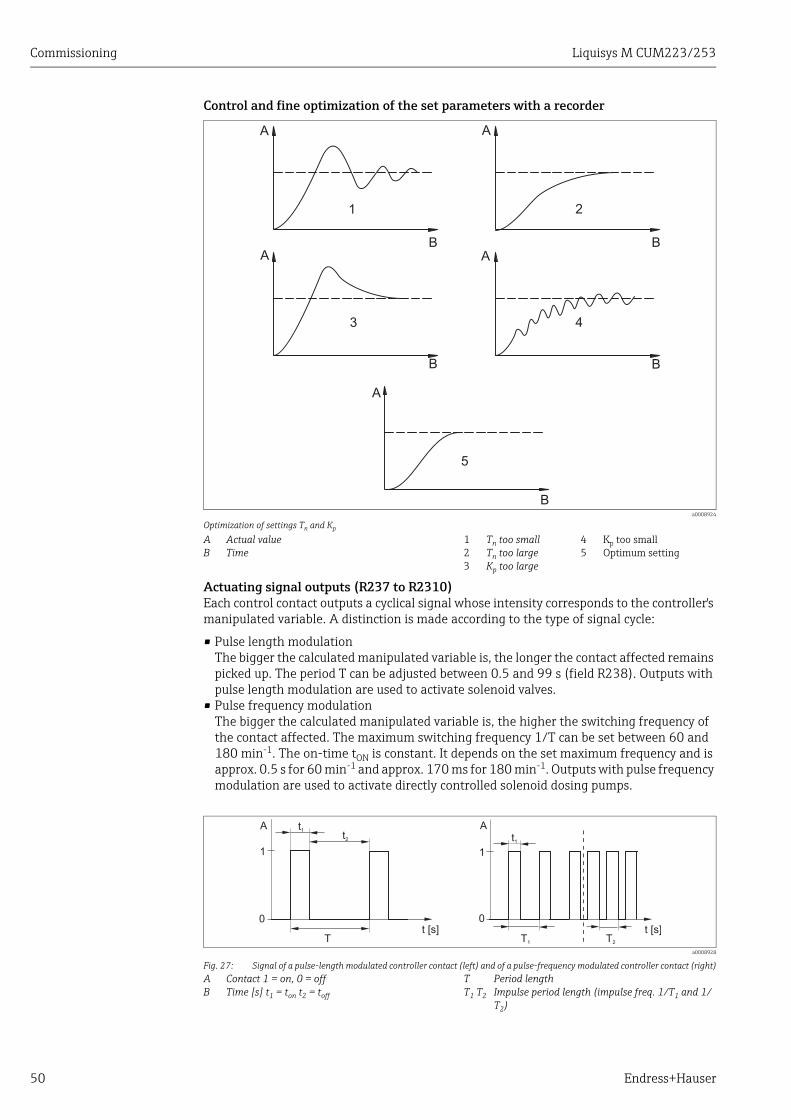
Control and fine optimization of the set parameters with a recorder
Actuating signal outputs (R237 to R2310)Each control contact outputs a cyclical signal whose intensity corresponds to the controller's manipulated variable. A distinction is made according to the type of signal cycle:
• Pulse length modulation The bigger the calculated manipulated variable is, the longer the contact affected remains picked up. The period T can be adjusted between 0.5 and 99 s (field R238). Outputs with pulse length modulation are used to activate solenoid valves.
• Pulse frequency modulationThe bigger the calculated manipulated variable is, the higher the switching frequency of the contact affected. The maximum switching frequency 1/T can be set between 60 and 180 min-1. The on-time tON is constant. It depends on the set maximum frequency and is approx. 0.5 s for 60 min-1 and approx. 170 ms for 180 min-1. Outputs with pulse frequency modulation are used to activate directly controlled solenoid dosing pumps.
a0008924
Optimization of settings Tn and Kp
AB
Actual valueTime
123
Tn too smallTn too largeKp too large
45
Kp too smallOptimum setting
a0008928
Fig. 27: Signal of a pulse-length modulated controller contact (left) and of a pulse-frequency modulated controller contact (right)AB
Contact 1 = on, 0 = offTime [s] t1 = ton t2 = toff
TT1 T2
Period lengthImpulse period length (impulse freq. 1/T1 and 1/T2)
A
B
A
BA
B
A
B
A
B
1 2
3 4
5
A
1
0
Tt [s]
A
t [s]
t1
t2 t1
1
0
T1 T2
Liquisys M CUM223/253 Commissioning
Endress+Hauser 51
Constant controllerVia the current output 2, the minimum actuating variable (0 %) of the controller is output with 0/4 mA and the maximum actuating variable (100%) of the controller is output with 20 mA.
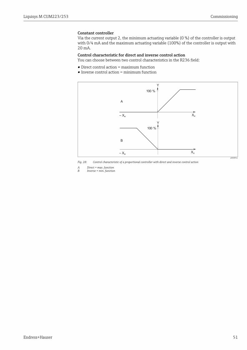
Control characteristic for direct and inverse control actionYou can choose between two control characteristics in the R236 field:
• Direct control action = maximum function• Inverse control action = minimum function
a0008941
Fig. 28: Control characteristic of a proportional controller with direct and inverse control action
A Direct = max. functionB Inverse = min. function
XW
XW
– XW
– XW
100 %
100 %
Y
Y
A
B
Commissioning Liquisys M CUM223/253
52 Endress+Hauser
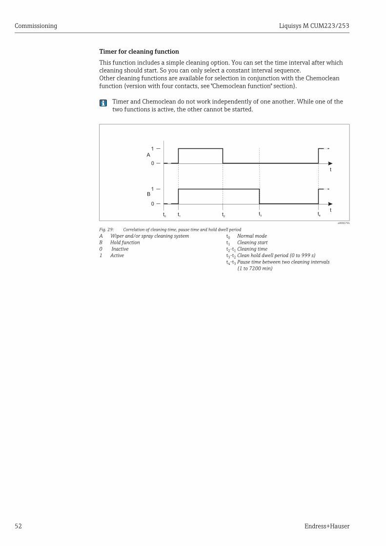
Timer for cleaning function
This function includes a simple cleaning option. You can set the time interval after which cleaning should start. So you can only select a constant interval sequence.Other cleaning functions are available for selection in conjunction with the Chemoclean function (version with four contacts, see "Chemoclean function" section).
Timer and Chemoclean do not work independently of one another. While one of the two functions is active, the other cannot be started.
a0006794
Fig. 29: Correlation of cleaning time, pause time and hold dwell periodAB01
Wiper and/or spray cleaning systemHold function InactiveActive
t0t1t2-t1t3-t2t4-t3
Normal modeCleaning startCleaning time Clean hold dwell period (0 to 999 s)Pause time between two cleaning intervals(1 to 7200 min)
A
B
1
0
t1 t2
1
0
t3
t
t
t4t0
Liquisys M CUM223/253 Commissioning
Endress+Hauser 53
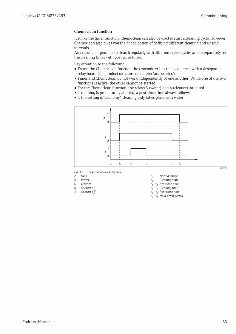
Chemoclean function
Just like the timer function, Chemoclean can also be used to start a cleaning cycle. However, Chemoclean also gives you the added option of defining different cleaning and rinsing intervals.As a result, it is possible to clean irregularly with different repeat cycles and to separately set the cleaning times with post rinse times.
Pay attention to the following:• To use the Chemoclean function the transmitter has to be equipped with a designated
relay board (see product structure or chapter "accessories").• Timer and Chemoclean do not work independently of one another. While one of the two
functions is active, the other cannot be started.• For the Chemoclean function, the relays 3 (water) and 4 (cleaner) are used.• If cleaning is prematurely aborted, a post rinse time always follows.• If the setting is "Economy", cleaning only takes place with water.
a0006793
Fig. 30: Sequence of a cleaning cycleABC01
HoldWaterCleanerContact onContact off
t0t1t2 - t1t3 - t2t4 - t3t5 - t4
Normal modeCleaning startPre-rinse timeCleaning timePost rinse timeHold dwell period
A
B
C
t0 t1 t2 t3 t4 t5
0
0
0
1
1
1
Commissioning Liquisys M CUM223/253
54 Endress+Hauser
Basic version does not include functions in italic.
Coding Field Setting range(Factory settings, bold)
Display Info
RRELAY function group
Relay contact settings.
R1Select contact to be configured
Rel1Rel2Rel3Rel4
Rel3 (water) and Rel4 (cleaner) are only available with the relevant version of the transmitter.If Chemoclean is used as the cleaning method, Rel4 is not available.
R2 (1)
Configure limit contactor for turbidity measurement
LC PV = limit contactor TU (1)LC °C = limit contactor T (2)PID controller (3)Timer (4)Clean = Chemoclean (5)
PV = process valueIf Rel4 is selected in the R1 field, Clean = Chemoclean cannot be selected.By confirming with ENTER, another relay function already switched on is switched off and its settings are reset to the factory settings.
R211 Switch function of R2 (1) off or on
OffOn All the settings are retained.
R212 Enter the switch-on point of the contact
9999 FNU9999 NTU9999 ppm / 3000 ppm9999 mg/l / 3000 mg/l300.0 g/l / 3 g/l99.99 kg/l99.99 t/m200.0 %
Never set the switch-on point and the switch-off point to the same value!(Only the operating mode selected in A1 is displayed.)If two factory settings are displayed the one on the left side stands for CUS41 the one on the right side stands for CUS31.
R213 Enter the switch-off point of the contact
9999 FNU9999 NTU9999 ppm / 3000 ppm9999 mg/l / 3000 mg/l300.0 g/l / 3 g/l99.99 kg/l99.99 t/m200.0 %
Entering a switch-off point selects either a Max contact (switch-off point < switch-on point) or a Min contact (switch-off point > switch-on point), thereby implementing a hysteresis that is constantly required (see "Illustration of the alarm and limit functions" figure).If two factory settings are displayed the one on the left side stands for CUS41 the one on the right side stands for CUS31.
R214 Enter pick-up delay0 s0 to 2000 s
R215 Enter drop-out delay 0 s0 to 2000 s
R
RELAIS
R1
Sel.Relay
Rel1
R2
Sel.Type
LC PV
R211
Function
off
FNU
R2129999
On value
FNU
R2139999
Off value
s
R214
On Delay
0
s
R215
Off Delay
0
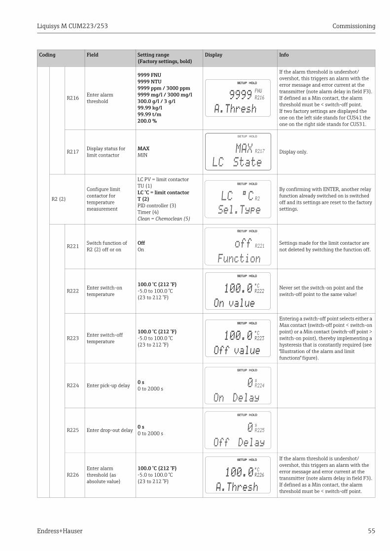
Liquisys M CUM223/253 Commissioning
Endress+Hauser 55
R216 Enter alarm threshold
9999 FNU9999 NTU9999 ppm / 3000 ppm9999 mg/l / 3000 mg/l300.0 g/l / 3 g/l99.99 kg/l99.99 t/m200.0 %
If the alarm threshold is undershot/overshot, this triggers an alarm with the error message and error current at the transmitter (note alarm delay in field F3).If defined as a Min contact, the alarm threshold must be < switch-off point.If two factory settings are displayed the one on the left side stands for CUS41 the one on the right side stands for CUS31.
R217 Display status for limit contactor
MAXMIN
Display only.
R2 (2)
Configure limit contactor for temperature measurement
LC PV = limit contactor TU (1)LC °C = limit contactor T (2)PID controller (3)Timer (4)Clean = Chemoclean (5)
By confirming with ENTER, another relay function already switched on is switched off and its settings are reset to the factory settings.
R221Switch function of R2 (2) off or on
OffOn
Settings made for the limit contactor are not deleted by switching the function off.
R222Enter switch-on temperature
100.0 °C (212 °F)-5.0 to 100.0 °C(23 to 212 °F)
Never set the switch-on point and the switch-off point to the same value!
R223Enter switch-off temperature
100.0 °C (212 °F)-5.0 to 100.0 °C(23 to 212 °F)
Entering a switch-off point selects either a Max contact (switch-off point < switch-on point) or a Min contact (switch-off point > switch-on point), thereby implementing a hysteresis that is constantly required (see "Illustration of the alarm and limit functions" figure).
R224 Enter pick-up delay 0 s0 to 2000 s
R225 Enter drop-out delay0 s0 to 2000 s
R226Enter alarm threshold (as absolute value)
100.0 °C (212 °F)-5.0 to 100.0 °C(23 to 212 °F)
If the alarm threshold is undershot/overshot, this triggers an alarm with the error message and error current at the transmitter (note alarm delay in field F3).If defined as a Min contact, the alarm threshold must be < switch-off point.
Coding Field Setting range(Factory settings, bold)
Display Info
FNU
R2169999
A.Thresh
R217
LC State
MAX
R2
Sel.Type
LC °C
R221
Function
off
R222
¡C
100.0
On value
R223
¡C
100.0
Off value
R224
s
On Delay
0
R225
s
Off Delay
0
R226
¡C
100.0
A.Thresh
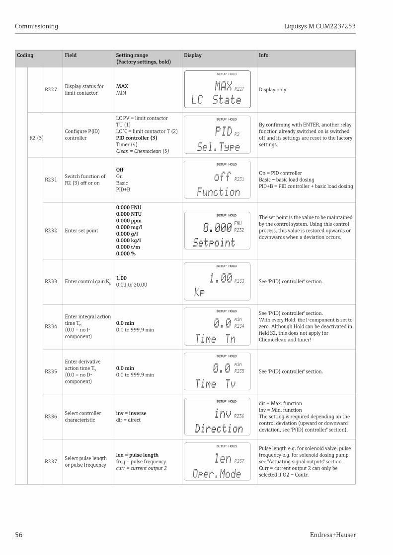
Commissioning Liquisys M CUM223/253
56 Endress+Hauser
R227 Display status for limit contactor
MAXMIN
Display only.
R2 (3)Configure P(ID) controller
LC PV = limit contactor TU (1)LC °C = limit contactor T (2)PID controller (3)Timer (4)Clean = Chemoclean (5)
By confirming with ENTER, another relay function already switched on is switched off and its settings are reset to the factory settings.
R231Switch function of R2 (3) off or on
OffOnBasicPID+B
On = PID controllerBasic = basic load dosingPID+B = PID controller + basic load dosing
R232 Enter set point
0.000 FNU0.000 NTU0.000 ppm 0.000 mg/l 0.000 g/l 0.000 kg/l0.000 t/m0.000 %
The set point is the value to be maintained by the control system. Using this control process, this value is restored upwards or downwards when a deviation occurs.
R233 Enter control gain Kp 1.000.01 to 20.00 See "P(ID) controller" section.
R234
Enter integral action time Tn(0.0 = no I-component)
0.0 min0.0 to 999.9 min
See "P(ID) controller" section.With every Hold, the I-component is set to zero. Although Hold can be deactivated in field S2, this does not apply for Chemoclean and timer!
R235
Enter derivative action time Tv (0.0 = no D-component)
0.0 min0.0 to 999.9 min
See "P(ID) controller" section.
R236 Select controller characteristic
inv = inversedir = direct
dir = Max. functioninv = Min. functionThe setting is required depending on the control deviation (upward or downward deviation, see "P(ID) controller" section).
R237 Select pulse length or pulse frequency
len = pulse lengthfreq = pulse frequencycurr = current output 2
Pulse length e.g. for solenoid valve, pulse frequency e.g. for solenoid dosing pump, see "Actuating signal outputs" section.Curr = current output 2 can only be selected if O2 = Contr.
Coding Field Setting range(Factory settings, bold)
Display Info
R227
LC State
MAX
R2
Sel.Type
PID
R231
Function
off
FNU
R2320.000
Setpoint
R233
Kp
1.00
R234
min
Time Tn
0.0
R235
min
Time Tv
0.0
R236inv
Direction
R237
Oper.Mode
len
Liquisys M CUM223/253 Commissioning
Endress+Hauser 57
R238 Enter pulse interval 10.0 s0.5 to 999.9 s
This field only appears if pulse length is selected in R237.If pulse frequency is selected, R238 is skipped and entries continue with R239.
R239Enter maximum pulse frequency of the adjuster
120 min-1
60 to 180 min-1
This field only appears if pulse frequency is selected in R237. If pulse length is selected, R239 is skipped and entries continue with R2310.
R2310Enter minimum switch-on time tON
0.3 s0.1 to 5.0 s
This field only appears if pulse length is selected in R237.
R2311 Enter basic load 0 %0 to 40 %
When you select the basic load, you enter the desired dosing quantity.
100% basic load would correspond to:– Constantly on for R237 = len– Fmax at R237 = freq (field R239)– 20 mA at R237 = curr
R2 (4) Configure cleaning function (timer)
LC PV = limit contactor TU (1)LC °C = limit contactor T (2)PID controller (3)Timer (4)Clean = Chemoclean (5)
Cleaning only takes place with one cleaning agent (usually water).By confirming with ENTER, another relay function already switched on is switched off and its settings are reset to the factory settings.
R241 Switch function of R2 (4) off or on
OffOn
Settings made for the timer are not deleted by switching the function off.
R242Enter rinsing/cleaning time
30 s0 to 999 s
Settings for Hold and relay are active for this time.
R243 Enter pause time 360 min1 to 7200 min
The pause time is the time between two cleaning cycles (see "Timer for cleaning function" section).
R244 Enter minimum pause time
120 min1 to R243 min
The minimum pause time prevents constant cleaning if a cleaning trigger is present.
Coding Field Setting range(Factory settings, bold)
Display Info
R238
s
PulsePer.
10.0
R239
1/min
Max.PFreq
120
R2310
s
Min.PTime
0.3
R2311
%
BasicLoad
0
R2
Sel.Type
Timer
R241
Function
off
R242
s
RinseTime
30
R243
min
PauseTime
360
R244
min
Min.Pause
120
Commissioning Liquisys M CUM223/253
58 Endress+Hauser
R2 (5)
Configure cleaning with Chemoclean (for version with four contacts , Chemoclean option and contacts 3 and 4 assigned)
LC PV = limit contactor TU(1)LC °C = limit contactor T (2)PID controller (3)Timer (4)Clean = Chemoclean (5)
See "Chemoclean function" section.By confirming with ENTER, another relay function already switched on is switched off and its settings are reset to the factory settings.
R251 Switch function of R2 (5) off or on
OffOn
R252 Select type of start pulse
Int = internal (time-controlled)Ext = external (digital input 2)I+ext = internal + externalI+stp = internal, suppressed by external
The cycle for the "int" function is started by the end of the pause time (R257).No real time clock is available.External suppression is required for irregular time intervals (e.g. weekends).
R253 Enter pre-rinse time 20 s0 to 999 s
Rinsing with water takes place.
R254 Enter cleaning time 10 s0 to 999 s
Cleaning with cleaning agent and water takes place.
R255 Enter post rinse time 20 s0 to 999 s Rinsing with water takes place.
R256Enter number of repeat cycles
00 to 5 R253 to R255 is repeated.
R257 Enter pause time 360 min1 to 7200 min
The pause time is the time between two cleaning cycles (see "Timer function" section).
R258 Enter minimum pause time
120 min1 to R257 min
The minimum pause time prevents constant cleaning if an external cleaning start is present.
Coding Field Setting range(Factory settings, bold)
Display Info
R2
Sel.Type
Clean
R251
Function
off
R252
CleanTrig
int
R253
s
PreRinse
20
R254
s
CleanTime
10
R255
s
PostRinse
20
R256
Rep.Rate
0
R257
min
PauseTime
360
R258
min
Min.Pause
120
Liquisys M CUM223/253 Commissioning
Endress+Hauser 59
6.4.7 Concentration measurementThe basic version does not include functions in italic.
R259
Enter number of cleaning cycles without cleaning agent (economy function)
00 to 9
After cleaning with cleaner, up to 9 cleaning sessions can be carried out with water only until the next cleaning session with cleaner takes place.
Coding Field Setting range(Factory settings, bold)
Display Info
R259
EconomyCl
0
Coding Field Selection or range(factory settings bold)
Display Info
K Function group CONCENTRATION
Four different concentration curves can be entered in this function group.
K1
Selection of concentration curve, to be used to calculate the display value
11 to 4
The curves are independent of each other. Therefore, four different curves can be defined.
K2 Selection of table to be edited
21 to 4
The modification of a table (curve) is independent from the selected curve in K1.The selected table (curve) will not be overwritten until the input of all table values is complete.
K3 Select table optionreadedit
This selection applies to the concentration curve selected in K2.
K4Enter number of reference elements
11 to 10
Each element consists of two numeric values.
K5 Select element11 to number of element in K4assign
Any element can be edited.
K6 Enter turbidity value 0.00 %entire measuring range
The function chain K5 to K7 will be repeated automatically as many times as corresponds to the value in K4. Then the system jumps to K8.
K
CONCENTRA
K1
act.curve
1
K22
editCurve
K3
Table
read
K4
No. Elem.
1
K5
Sel.Elem.
1
K6
%
MeasValue
%
0.00

Commissioning Liquisys M CUM223/253
60 Endress+Hauser
K7 Enter concentration value
entire measuring range Measuring unit as selected in A2.
K8Message whether or not the table status is ok
yesno
Only displayIf not, then set table correctly (all previous settings are kept) or back to measurement mode (this makes the table invalid).
Coding Field Selection or range(factory settings bold)
Display Info
0.00kg/l
K7
concentr.
K8
Status ok
yes
Liquisys M CUM223/253 Commissioning
Endress+Hauser 61
6.4.8 Service
Coding Field Setting range(Factory settings, bold)
Display Info
SSERVICE function group Service function settings.
S1 Select language
ENG = EnglishGER = GermanFRA = FrenchITA = ItalianNL = DutchESP = Spanish
S2 Configure Hold
S+C = Hold during configuration and calibrationCal = Hold during calibrationSetup = Hold during configurationNone = no Hold
S = setupC = calibration
S3 Manual Hold offon
The setting is retained even in the event of a power failure.
S4Enter Hold dwell period
10 s0 to 999 s
S5Enter SW upgrade release code (Plus Package)
00000 to 9999
You can find the code on the nameplate.If an incorrect code is entered, you are taken back to the measurement menu.The number is edited with the PLUS or MINUS key and confirmed with the ENTER key."1" is displayed if the code is active.
S6Enter SW upgrade release code Chemoclean
00000 to 9999
You can find the code on the nameplate.If an incorrect code is entered, you are taken back to the measurement menu.The number is edited with the PLUS or MINUS key and confirmed with the ENTER key."1" is displayed if the code is active.
S7 Order number is displayed
CUM253-T If the device is upgraded, the order code is not automatically adjusted.
S8 Serial number is displayed
880CB405G
S
SERVICE
S1
Language
ENG
S2
Auto HOLD
S+C
S3
Man. HOLD
off
S4
s
Cont.Time
10
S50
PlusCode
S60
CleanCode
S7order
CUM253-T
S8SerNo
880CB405G
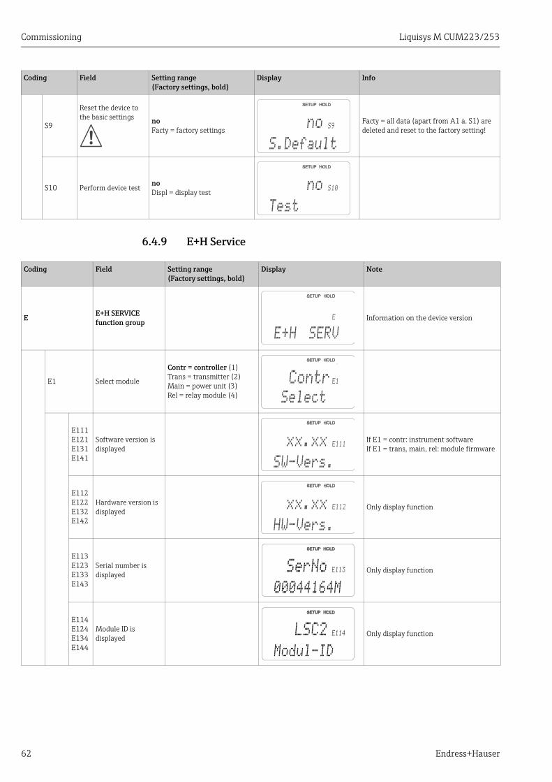
Commissioning Liquisys M CUM223/253
62 Endress+Hauser
6.4.9 E+H Service
S9
Reset the device to the basic settings no
Facty = factory settingsFacty = all data (apart from A1 a. S1) are deleted and reset to the factory setting!
S10 Perform device testnoDispl = display test
Coding Field Setting range(Factory settings, bold)
Display Info
S9
S.Default
no
S10
Test
no
Coding Field Setting range(Factory settings, bold)
Display Note
E E+H SERVICE function group
Information on the device version
E1 Select module
Contr = controller (1)Trans = transmitter (2)Main = power unit (3)Rel = relay module (4)
E111E121E131E141
Software version is displayed
If E1 = contr: instrument softwareIf E1 = trans, main, rel: module firmware
E112E122E132E142
Hardware version is displayed
Only display function
E113E123E133E143
Serial number is displayed Only display function
E114E124E134E144
Module ID is displayed Only display function
E
E+H SERV
E1
Select
Contr
E111
SW-Vers.
xx.xx
E112
HW-Vers.
xx.xx
E113SerNo
00044164M
E114LSC2
Modul-ID
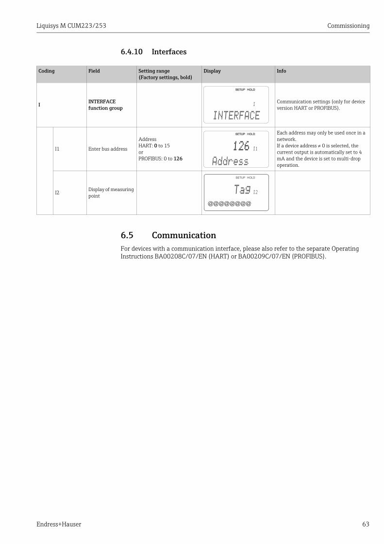
Liquisys M CUM223/253 Commissioning
Endress+Hauser 63
6.4.10 Interfaces
6.5 CommunicationFor devices with a communication interface, please also refer to the separate Operating Instructions BA00208C/07/EN (HART) or BA00209C/07/EN (PROFIBUS).
Coding Field Setting range(Factory settings, bold)
Display Info
I INTERFACE function group
Communication settings (only for device version HART or PROFIBUS).
I1 Enter bus address
AddressHART: 0 to 15orPROFIBUS: 0 to 126
Each address may only be used once in a network.If a device address 0 is selected, the current output is automatically set to 4 mA and the device is set to multi-drop operation.
I2Display of measuring point
I
INTERFACE
I1
Address
126126
I2
@@@@@@@@
Tag
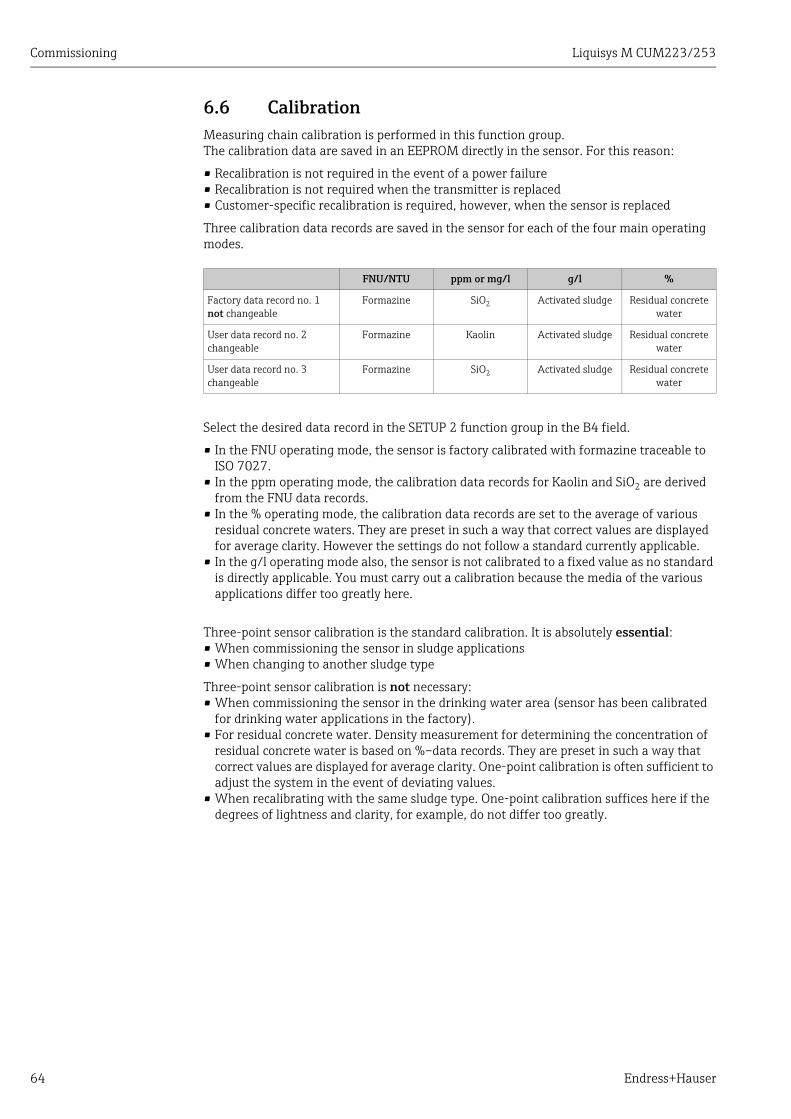
Commissioning Liquisys M CUM223/253
64 Endress+Hauser
6.6 CalibrationMeasuring chain calibration is performed in this function group. The calibration data are saved in an EEPROM directly in the sensor. For this reason:
• Recalibration is not required in the event of a power failure• Recalibration is not required when the transmitter is replaced• Customer-specific recalibration is required, however, when the sensor is replaced
Three calibration data records are saved in the sensor for each of the four main operating modes.
Select the desired data record in the SETUP 2 function group in the B4 field.
• In the FNU operating mode, the sensor is factory calibrated with formazine traceable to ISO 7027.
• In the ppm operating mode, the calibration data records for Kaolin and SiO2 are derived from the FNU data records.
• In the % operating mode, the calibration data records are set to the average of various residual concrete waters. They are preset in such a way that correct values are displayed for average clarity. However the settings do not follow a standard currently applicable.
• In the g/l operating mode also, the sensor is not calibrated to a fixed value as no standard is directly applicable. You must carry out a calibration because the media of the various applications differ too greatly here.
Three-point sensor calibration is the standard calibration. It is absolutely essential:• When commissioning the sensor in sludge applications• When changing to another sludge type
Three-point sensor calibration is not necessary: • When commissioning the sensor in the drinking water area (sensor has been calibrated
for drinking water applications in the factory).• For residual concrete water. Density measurement for determining the concentration of
residual concrete water is based on %–data records. They are preset in such a way that correct values are displayed for average clarity. One-point calibration is often sufficient to adjust the system in the event of deviating values.
• When recalibrating with the same sludge type. One-point calibration suffices here if the degrees of lightness and clarity, for example, do not differ too greatly.
FNU/NTU ppm or mg/l g/l %
Factory data record no. 1not changeable
Formazine SiO2 Activated sludge Residual concrete water
User data record no. 2changeable
Formazine Kaolin Activated sludge Residual concrete water
User data record no. 3changeable
Formazine SiO2 Activated sludge Residual concrete water
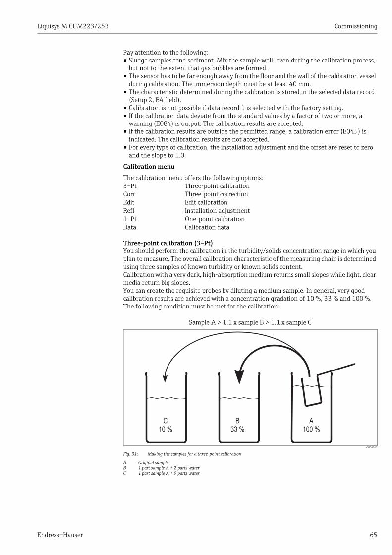
Liquisys M CUM223/253 Commissioning
Endress+Hauser 65
Pay attention to the following:• Sludge samples tend sediment. Mix the sample well, even during the calibration process,
but not to the extent that gas bubbles are formed.• The sensor has to be far enough away from the floor and the wall of the calibration vessel
during calibration. The immersion depth must be at least 40 mm.• The characteristic determined during the calibration is stored in the selected data record
(Setup 2, B4 field).• Calibration is not possible if data record 1 is selected with the factory setting.• If the calibration data deviate from the standard values by a factor of two or more, a
warning (E084) is output. The calibration results are accepted.• If the calibration results are outside the permitted range, a calibration error (E045) is
indicated. The calibration results are not accepted.• For every type of calibration, the installation adjustment and the offset are reset to zero
and the slope to 1.0.
Calibration menu
The calibration menu offers the following options:
Three-point calibration (3–Pt)You should perform the calibration in the turbidity/solids concentration range in which you plan to measure. The overall calibration characteristic of the measuring chain is determined using three samples of known turbidity or known solids content.Calibration with a very dark, high-absorption medium returns small slopes while light, clear media return big slopes.You can create the requisite probes by diluting a medium sample. In general, very good calibration results are achieved with a concentration gradation of 10 %, 33 % and 100 %. The following condition must be met for the calibration:
a0006961
Fig. 31: Making the samples for a three-point calibration
A Original sampleB 1 part sample A + 2 parts waterC 1 part sample A + 9 parts water
3–Pt Three-point calibrationCorr Three-point correctionEdit Edit calibrationRefl Installation adjustment1–Pt One-point calibrationData Calibration data
Sample A > 1.1 x sample B > 1.1 x sample C
Commissioning Liquisys M CUM223/253
66 Endress+Hauser
A different dilution ratio should be selected for very high-absorption media to achieve accurate calibration results. Instead of 100 % – 33 % – 10 %, you can use dilution ratios of 100 % – 20 % – 5 % or 100% – 10 % – 3.3 %.If the scattered light of a light sample hits a sensor that is calibrated for a dark medium, it can happen that the signal value is so high that it is above the calibration curve.
Three-point correction (Corr)If the calibration was performed with an unknown sample concentration but with a defined dilution, the correct value determined afterwards in the laboratory is entered here.
Edit calibration (Edit)If each of the samples has been determined afterwards in the laboratory, the correction for the calibration is entered here.
Installation adjustment (Refl)In installation adjustment, backscatter from the immediate sensor environment is compensated. Installation adjustment must be performed with a medium whose turbidity is lower than 2 FNU or 5 ppm.
One-point calibration (1–Pt)In the area of TS/concentration measurement, one-point calibration is used to change the conversion factor (field C166). The slopes are not changed. In the FNU range, the two slope values are adjusted by a one-point calibration. This is possible because the conversion factor in the FNU range is always 1 and the editing range is limited to 4000 FNU. In this way, the two curves are always increasing and the calibration remains clear.In the ppm range, the slope values are adjusted up to 500 ppm. For higher values, the conversion factor is changed.
Calibration data (Data)Here, you can display the calibration points 1 to 3, slope 1 and 2 and the conversion factor.With three-point calibration, the curves used in the algorithm are adjusted as precisely as possible using the data points acquired. The difference between the ideal curve of the algorithm and the three actual calibration points can be found as a correction factor in the C161, C162 and C163 fields of the data function. The correction values are indicated in %. The values should be as close to 100 % as possible. Values from 70 to 80 % are acceptable. 50 % in one or two calibration points clearly indicates a problematic calibration. A warning (E084) is output here for this reason. This can mean that significant deviations can occur between the calibration points. The calibration points themselves are always retrieved correctly.
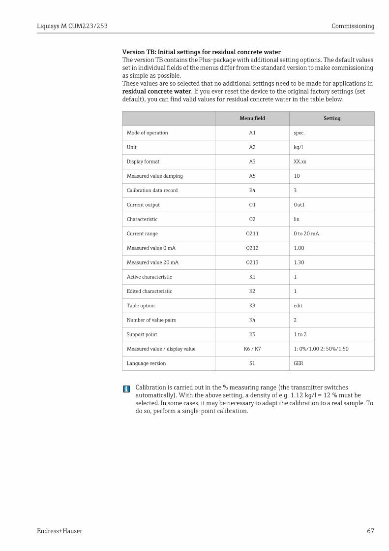
Liquisys M CUM223/253 Commissioning
Endress+Hauser 67
Version TB: Initial settings for residual concrete waterThe version TB contains the Plus-package with additional setting options. The default values set in individual fields of the menus differ from the standard version to make commissioning as simple as possible.These values are so selected that no additional settings need to be made for applications in residual concrete water. If you ever reset the device to the original factory settings (set default), you can find valid values for residual concrete water in the table below.
Calibration is carried out in the % measuring range (the transmitter switches automatically). With the above setting, a density of e.g. 1.12 kg/l = 12 % must be selected. In some cases, it may be necessary to adapt the calibration to a real sample. To do so, perform a single-point calibration.
Menu field Setting
Mode of operation A1 spec.
Unit A2 kg/l
Display format A3 XX.xx
Measured value damping A5 10
Calibration data record B4 3
Current output O1 Out1
Characteristic O2 lin
Current range O211 0 to 20 mA
Measured value 0 mA O212 1.00
Measured value 20 mA O213 1.30
Active characteristic K1 1
Edited characteristic K2 1
Table option K3 edit
Number of value pairs K4 2
Support point K5 1 to 2
Measured value / display value K6 / K7 1: 0%/1.00 2: 50%/1.50
Language version S1 GER
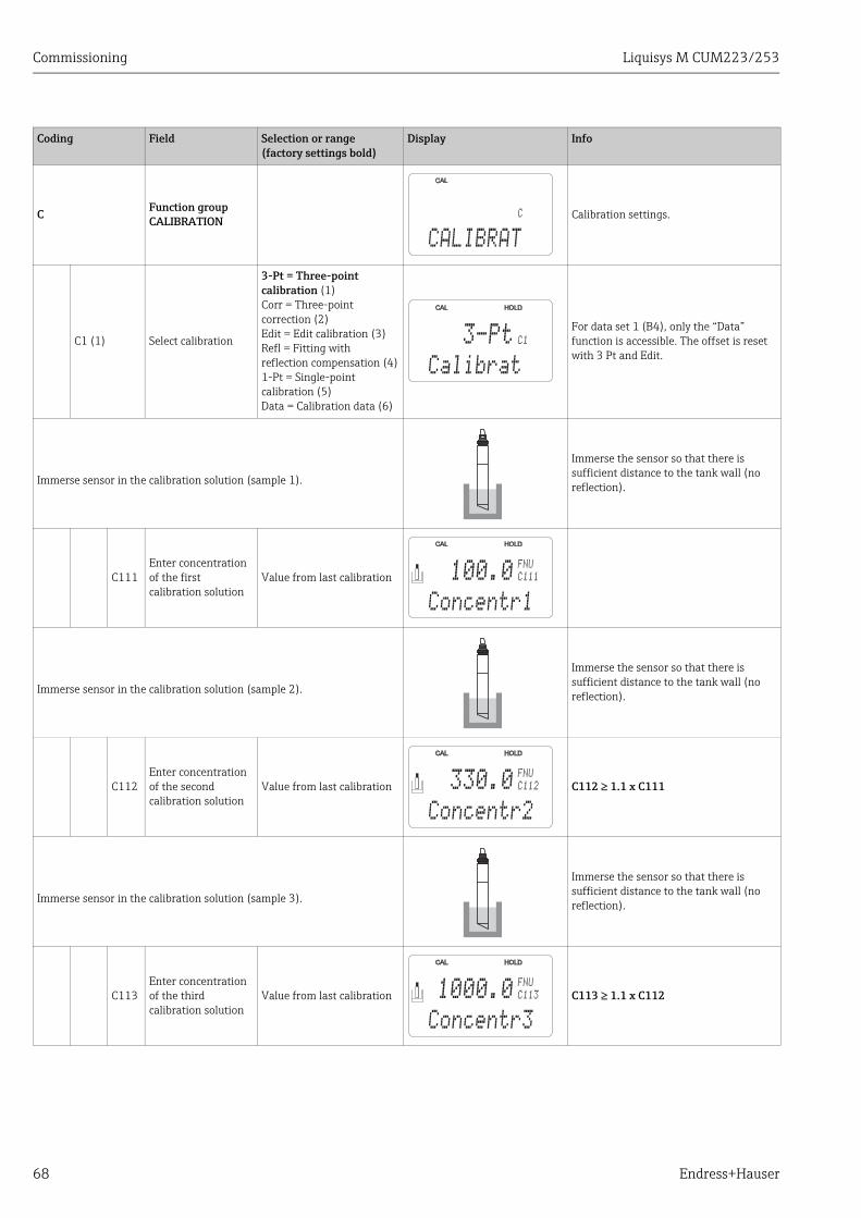
Commissioning Liquisys M CUM223/253
68 Endress+Hauser
Coding Field Selection or range(factory settings bold)
Display Info
C Function group CALIBRATION Calibration settings.
C1 (1) Select calibration
3-Pt = Three-point calibration (1)Corr = Three-point correction (2)Edit = Edit calibration (3)Refl = Fitting with reflection compensation (4)1-Pt = Single-point calibration (5)Data = Calibration data (6)
For data set 1 (B4), only the “Data” function is accessible. The offset is reset with 3 Pt and Edit.
Immerse sensor in the calibration solution (sample 1).
Immerse the sensor so that there is sufficient distance to the tank wall (no reflection).
C111Enter concentration of the first calibration solution
Value from last calibration
Immerse sensor in the calibration solution (sample 2).
Immerse the sensor so that there is sufficient distance to the tank wall (no reflection).
C112Enter concentration of the second calibration solution
Value from last calibration C112 1.1 x C111
Immerse sensor in the calibration solution (sample 3).
Immerse the sensor so that there is sufficient distance to the tank wall (no reflection).
C113Enter concentration of the third calibration solution
Value from last calibration C113 1.1 x C112
C
CALIBRAT
C13-Pt
Calibrat
C111
FNU
100.0
Concentr1
C112
FNU
330.0
Concentr2
C113
FNU
1000.0
Concentr3
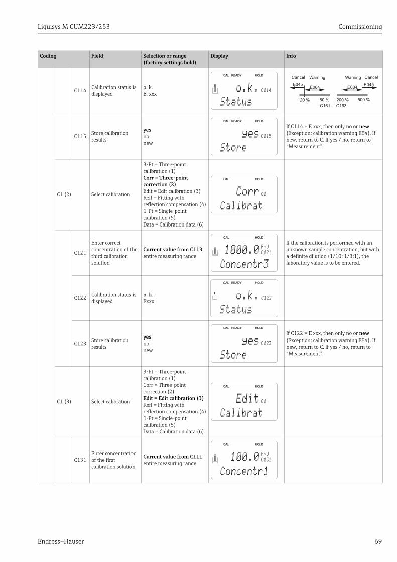
Liquisys M CUM223/253 Commissioning
Endress+Hauser 69
C114 Calibration status is displayed
o. k.E. xxx
C115 Store calibration results
yesnonew
If C114 = E xxx, then only no or new (Exception: calibration warning E84). If new, return to C. If yes / no, return to “Measurement”.
C1 (2) Select calibration
3-Pt = Three-point calibration (1)Corr = Three-point correction (2)Edit = Edit calibration (3)Refl = Fitting with reflection compensation (4)1-Pt = Single-point calibration (5)Data = Calibration data (6)
C121
Enter correct concentration of the third calibration solution
Current value from C113entire measuring range
If the calibration is performed with an unknown sample concentration, but with a definite dilution (1/10; 1/3;1), the laboratory value is to be entered.
C122 Calibration status is displayed
o. k.Exxx
C123 Store calibration results
yesnonew
If C122 = E xxx, then only no or new (Exception: calibration warning E84). If new, return to C. If yes / no, return to “Measurement”.
C1 (3) Select calibration
3-Pt = Three-point calibration (1)Corr = Three-point correction (2)Edit = Edit calibration (3)Refl = Fitting with reflection compensation (4)1-Pt = Single-point calibration (5)Data = Calibration data (6)
C131Enter concentration of the first calibration solution
Current value from C111 entire measuring range
Coding Field Selection or range(factory settings bold)
Display Info
C114o.k.
Status
E045E084 E084
E045
20 % 50 % 200 % 500 %
C161 ... C163
Cancel Warning CancelWarning
C115yes
Store
C1Corr
Calibrat
C121
FNU
1000.0
Concentr3
C122
Status
o.k.
C123yes
Store
C1Edit
Calibrat
C131
FNU
100.0
Concentr1
Commissioning Liquisys M CUM223/253
70 Endress+Hauser
C132Enter concentration of the second calibration solution
Current value from C112 C132 1.1 x C131
C133Enter concentration of the third calibration solution
Current value from C113 C133 1.1 x C132
C134Calibration status is displayed
o.k.Exxx
C135Store calibration results?
yesnonew
If C134 = E xxx, then only no or new (Exception: calibration warning E84). If new, return to C. If yes / no, return to “Measurement”.
C1 (4) Select calibration
3-Pt = Three-point calibration (1)Corr = Three-point correction (2)Edit = Edit calibration (3)Refl = Fitting with reflection compensation (4)1-Pt = Single-point calibration (5)Data = Calibration data (6)
Only for solutions = 2 FNU / 5 ppm! Backscatter from the immediate sensor environment is compensated for clear media.
C141Enter correct measured value
0.0 NTU0.0 to 2.0 NTU0.0 FNU0.0 to 2.0 FNU0.0 ppm0.0 to 5.0 ppm0.0 mg/l0.0 to 5.0 mg/l
Only for the ranges NTU, FNU, ppm, mg/l
C142 Calibration status is displayed
o.k.Exxx
C143 Store calibration results?
yesnonew
If C142 = E xxx, then only no or new (Exception: calibration warning E84). If new, return to C. If yes / no, return to “Measurement”.
Coding Field Selection or range(factory settings bold)
Display Info
C132
FNU
330.0
Concentr2
C133
FNU
1000.0
Concentr3
C134o.k.
Status
C135yes
Store
Refl
Calibrat
C1
C141
FNU
0.0
Real PV
C142o.k.
Status
C143yes
Store
Liquisys M CUM223/253 Commissioning
Endress+Hauser 71
C1 (5) Select calibration
3-Pt = Three-point calibration (1)Corr = Three-point correction (2)Edit = Edit calibration (3)Refl = Fitting with reflection compensation (4)1-Pt = Single-point calibration (5)Data = Calibration data (6)
For FNU:Adaption C164, C165
For ppm, mg/l: up to 500 - adaption C164, C165above 500 - adaption C166
For g/l, %:Adaption C166. An existing basic calibration (three-point) is corrected by the single-point calibration.
C151Enter current calibration value
Current measured valueEntire measuring range
C152 Calibration status is displayed
o.k.Exxx
C153 Store calibration results?
yesnonew
If C152 = E xxx, then only no or new (Exception: calibration warning E84). If new, return to C. If yes / no, return to “Measurement”.
C1 (6) Select calibration
3-Pt = Three-point calibration (1)Corr = Three-point correction (2)Edit = Edit calibration (3)Refl = Fitting with reflection compensation (4)1-Pt = Single-point calibration (5)Data = Calibration data (6)
C161 Calibration point 1 is displayed
Comparison value Deviation relative to standard sensor (= 100 %)
C162 Calibration point 2 is displayed Comparison value Deviation relative to standard sensor
(= 100 %)
C163 Calibration point 3 is displayed Comparison value Deviation relative to standard sensor
(= 100 %)
Coding Field Selection or range(factory settings bold)
Display Info
C11-Pt
Calibrat
C151
FNUFNU
Real PV
C152o.k.
Status
C153yes
Store
C1Data
Calibrat
C161
%
101.4
Concentr1
C162
%
99.3
Concentr2
C163
%
98.7
Concentr3
Commissioning Liquisys M CUM223/253
72 Endress+Hauser
C164 Slope 1 is displayed Current value Slope of characteristic 1 of the sensor
C165 Slope 2 is displayed Current value Slope of characteristic 2 of the sensor
C166Conversion factor is displayed Current value
Conversion factor of internal turbidity units into displayed unit
Coding Field Selection or range(factory settings bold)
Display Info
C164230
Slope 1
C165375
Slope 2
C1661
ConvFact
Liquisys M CUM223/253 Commissioning
Endress+Hauser 73
6.7 OffsetThe settings in the OFFSET function group can be used to calibrate the measurement to a reference measurement. This requires a linear shift of all the measured values, i.e. the adjustment is determined for one measured value, and all others are calculated using the same adjustment.
C07-CPM2x3xx-05-06-00-xx-005.eps
Fig. 32: Offset
X TimeY Measured valueA Calibrated valueB Current measured value
Following a calibration, the offset is automatically set to zero.
Y
X
A
B
Coding Field Setting range(Factory settings, bold)
Display Info
V Function group OFFSET
V1 Enter absolute value Current measured value
V2 Enter offset Current offset
V3 Calibration status is displayed
o.k.E xxx
V4Store calibration result?
yesnonew
If V3 = E xxx, then only no or new.If new, return to V.If yes/no, return to "Measurement".
V
OFFSET
V1
FNU
Real PV
0.0
V2
FNU
PV Offset
0.0
V3
Status
o.k.
V4
Store
yes
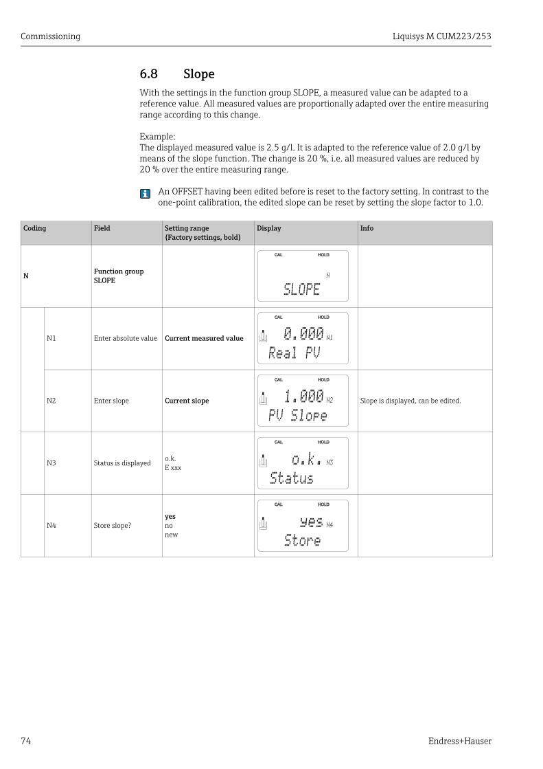
Commissioning Liquisys M CUM223/253
74 Endress+Hauser
6.8 SlopeWith the settings in the function group SLOPE, a measured value can be adapted to a reference value. All measured values are proportionally adapted over the entire measuring range according to this change.
Example:The displayed measured value is 2.5 g/l. It is adapted to the reference value of 2.0 g/l by means of the slope function. The change is 20 %, i.e. all measured values are reduced by 20 % over the entire measuring range.
An OFFSET having been edited before is reset to the factory setting. In contrast to the one-point calibration, the edited slope can be reset by setting the slope factor to 1.0.
Coding Field Setting range(Factory settings, bold)
Display Info
N Function group SLOPE
N1 Enter absolute value Current measured value
N2 Enter slope Current slope Slope is displayed, can be edited.
N3 Status is displayed o.k.E xxx
N4 Store slope?yesnonew
N
SLOPE
N10.000
Real PV
N21.000
PV Slope
N3o.k.
Status
N4yes
Store
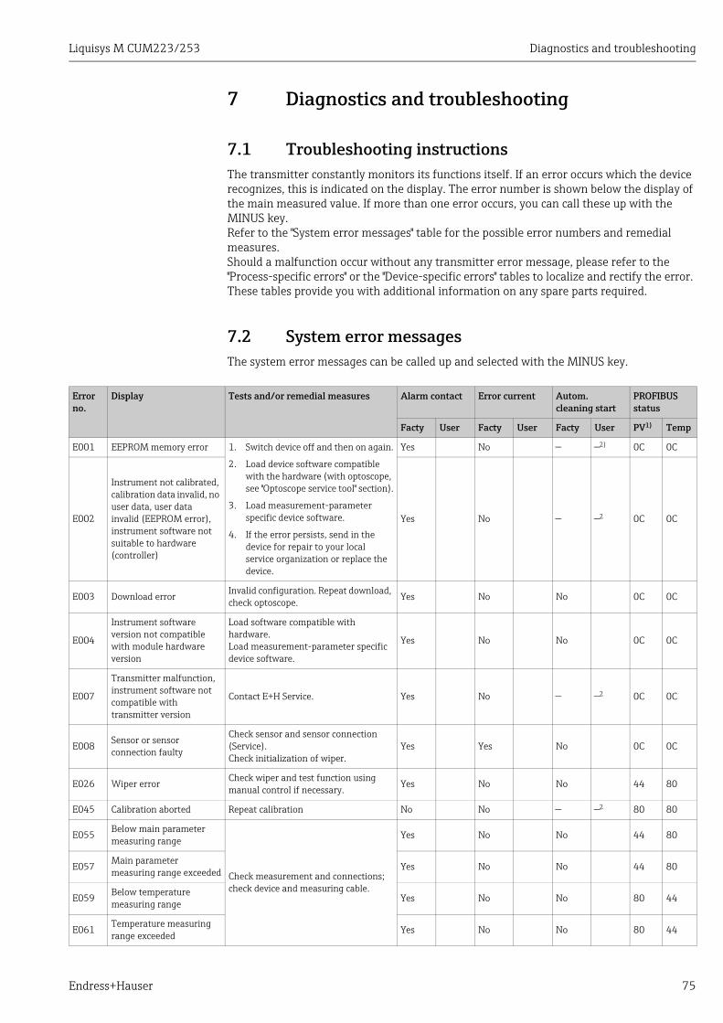
Liquisys M CUM223/253 Diagnostics and troubleshooting
Endress+Hauser 75
7 Diagnostics and troubleshooting
7.1 Troubleshooting instructionsThe transmitter constantly monitors its functions itself. If an error occurs which the device recognizes, this is indicated on the display. The error number is shown below the display of the main measured value. If more than one error occurs, you can call these up with the MINUS key.Refer to the "System error messages" table for the possible error numbers and remedial measures.Should a malfunction occur without any transmitter error message, please refer to the "Process-specific errors" or the "Device-specific errors" tables to localize and rectify the error. These tables provide you with additional information on any spare parts required.
7.2 System error messagesThe system error messages can be called up and selected with the MINUS key.
Error no.
Display Tests and/or remedial measures Alarm contact Error current Autom. cleaning start
PROFIBUS status
Facty User Facty User Facty User PV1) Temp
E001 EEPROM memory error 1. Switch device off and then on again.
2. Load device software compatible with the hardware (with optoscope, see "Optoscope service tool" section).
3. Load measurement-parameter specific device software.
4. If the error persists, send in the device for repair to your local service organization or replace the device.
Yes No — —2) 0C 0C
E002
Instrument not calibrated, calibration data invalid, no user data, user data invalid (EEPROM error), instrument software not suitable to hardware (controller)
Yes No — —2 0C 0C
E003 Download error Invalid configuration. Repeat download, check optoscope. Yes No No 0C 0C
E004
Instrument software version not compatible with module hardware version
Load software compatible with hardware.Load measurement-parameter specific device software.
Yes No No 0C 0C
E007
Transmitter malfunction, instrument software not compatible with transmitter version
Contact E+H Service. Yes No — —2 0C 0C
E008 Sensor or sensor connection faulty
Check sensor and sensor connection (Service).Check initialization of wiper.
Yes Yes No 0C 0C
E026 Wiper errorCheck wiper and test function using manual control if necessary. Yes No No 44 80
E045 Calibration aborted Repeat calibration No No — —2 80 80
E055Below main parameter measuring range
Check measurement and connections; check device and measuring cable.
Yes No No 44 80
E057 Main parameter measuring range exceeded Yes No No 44 80
E059 Below temperature measuring range
Yes No No 80 44
E061Temperature measuring range exceeded Yes No No 80 44
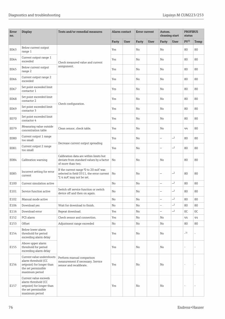
Diagnostics and troubleshooting Liquisys M CUM223/253
76 Endress+Hauser
E063Below current output range 1
Check measured value and current assignment.
Yes No No 80 80
E064 Current output range 1 exceeded Yes No No 80 80
E065 Below current output range 2
Yes No No 80 80
E066Current output range 2 exceeded Yes No No 80 80
E067 Set point exceeded limit contactor 1
Check configuration.
Yes No No 80 80
E068 Set point exceeded limit contactor 2
Yes No No 80 80
E069Set point exceeded limit contactor 3 Yes No No 80 80
E070 Set point exceeded limit contactor 4 Yes No No 80 80
E079Measuring value outside concentration table Clean sensor, check table. Yes No No 44 80
E080 Current output 1 range too small
Decrease current output spreading
Yes No — —2 80 80
E081 Current output 2 range too small
Yes No — —2 80 80
E084 Calibration warningCalibration data are within limits but deviate from standard values by a factor of more than two.
No No No 80 80
E085 Incorrect setting for error current
If the current range "0 to 20 mA" was selected in field O311, the error current "2.4 mA" may not be set.
No No — —2 80 80
E100 Current simulation active No No — —2 80 80
E101 Service function active Switch off service function or switch device off and then on again.
No No — —2 80 80
E102 Manual mode active No No — —2 80 80
E106 Download yes Wait for download to finish. No No — —2 80 80
E116 Download error Repeat download. Yes No — —2 0C 0C
E152 PCS alarm Check sensor and connection. Yes No No 44 44
E153 Offset Adjustment range exceeded No No No 80 80
E154Below lower alarm threshold for period exceeding alarm delay
Perform manual comparison measurement if necessary. Service sensor and recalibrate.
Yes No No -3) -
E155Above upper alarm threshold for period exceeding alarm delay
Yes No No - -
E156
Current value undershoots alarm threshold (CC setpoint) for longer than the set permissible maximum period
Yes No No - -
E157
Current value exceeds alarm threshold (CC setpoint) for longer than the set permissible maximum period
Yes No No - -
Error no.
Display Tests and/or remedial measures Alarm contact Error current Autom. cleaning start
PROFIBUS status
Facty User Facty User Facty User PV1) Temp
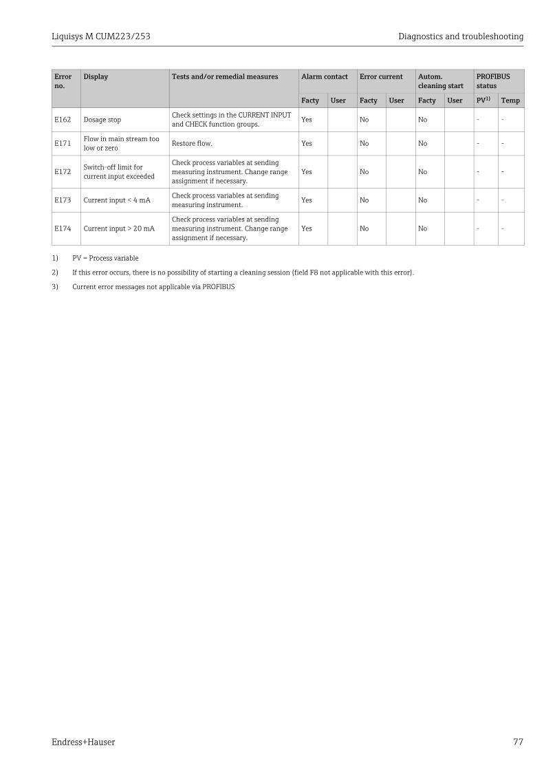
Liquisys M CUM223/253 Diagnostics and troubleshooting
Endress+Hauser 77
E162 Dosage stopCheck settings in the CURRENT INPUT and CHECK function groups. Yes No No - -
E171 Flow in main stream too low or zero Restore flow. Yes No No - -
E172Switch-off limit for current input exceeded
Check process variables at sending measuring instrument. Change range assignment if necessary.
Yes No No - -
E173 Current input < 4 mA Check process variables at sending measuring instrument.
Yes No No - -
E174 Current input > 20 mACheck process variables at sending measuring instrument. Change range assignment if necessary.
Yes No No - -
1) PV = Process variable
2) If this error occurs, there is no possibility of starting a cleaning session (field F8 not applicable with this error).
3) Current error messages not applicable via PROFIBUS
Error no.
Display Tests and/or remedial measures Alarm contact Error current Autom. cleaning start
PROFIBUS status
Facty User Facty User Facty User PV1) Temp
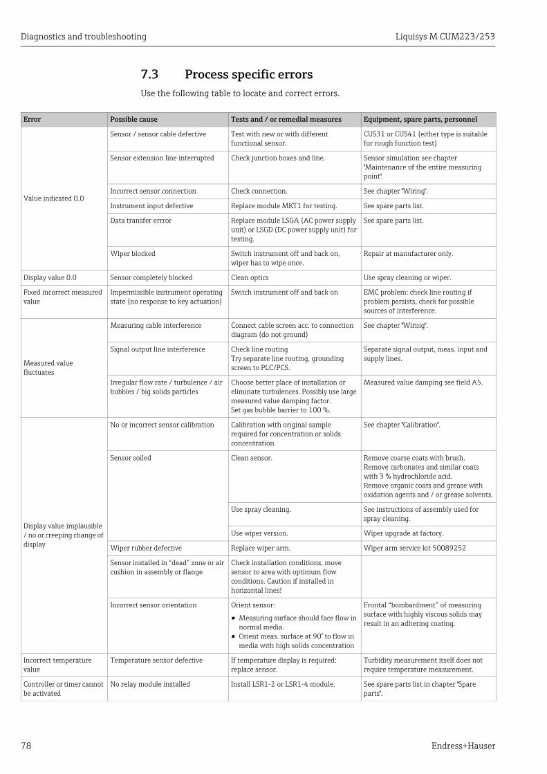
Diagnostics and troubleshooting Liquisys M CUM223/253
78 Endress+Hauser
7.3 Process specific errorsUse the following table to locate and correct errors.
Error Possible cause Tests and / or remedial measures Equipment, spare parts, personnel
Value indicated 0.0
Sensor / sensor cable defective Test with new or with different functional sensor.
CUS31 or CUS41 (either type is suitable for rough function test)
Sensor extension line interrupted Check junction boxes and line. Sensor simulation see chapter "Maintenance of the entire measuring point".
Incorrect sensor connection Check connection. See chapter "Wiring".
Instrument input defective Replace module MKT1 for testing. See spare parts list.
Data transfer errror Replace module LSGA (AC power supply unit) or LSGD (DC power supply unit) for testing.
See spare parts list.
Wiper blocked Switch instrument off and back on, wiper has to wipe once.
Repair at manufacturer only.
Display value 0.0 Sensor completely blocked Clean optics Use spray cleaning or wiper.
Fixed incorrect measured value
Impermissible instrument operating state (no response to key actuation)
Switch instrument off and back on EMC problem: check line routing if problem persists, check for possible sources of interference.
Measured value fluctuates
Measuring cable interference Connect cable screen acc. to connection diagram (do not ground)
See chapter "Wiring".
Signal output line interference Check line routingTry separate line routing, grounding screen to PLC/PCS.
Separate signal output, meas. input and supply lines.
Irregular flow rate / turbulence / air bubbles / big solids particles
Choose better place of installation or eliminate turbulences. Possibly use large measured value damping factor.Set gas bubble barrier to 100 %.
Measured value damping see field A5.
Display value implausible / no or creeping change of display
No or incorrect sensor calibration Calibration with original sample required for concentration or solids concentration
See chapter "Calibration".
Sensor soiled Clean sensor. Remove coarse coats with brush.Remove carbonates and similar coats with 3 % hydrochloride acid.Remove organic coats and grease with oxidation agents and / or grease solvents.
Use spray cleaning. See instructions of assembly used for spray cleaning.
Use wiper version. Wiper upgrade at factory.
Wiper rubber defective Replace wiper arm. Wiper arm service kit 50089252
Sensor installed in “dead” zone or air cushion in assembly or flange
Check installation conditions, move sensor to area with optimum flow conditions. Caution if installed in horizontal lines!
Incorrect sensor orientation Orient sensor:
• Measuring surface should face flow in normal media.
• Orient meas. surface at 90° to flow in media with high solids concentration
Frontal “bombardment” of measuring surface with highly viscous solids may result in an adhering coating.
Incorrect temperature value
Temperature sensor defective If temperature display is required: replace sensor.
Turbidity measurement itself does not require temperature measurement.
Controller or timer cannot be activated
No relay module installed Install LSR1-2 or LSR1-4 module. See spare parts list in chapter "Spare parts".
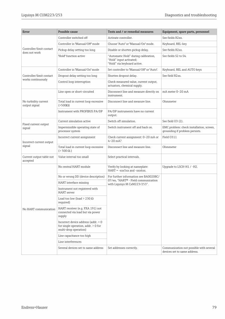
Liquisys M CUM223/253 Diagnostics and troubleshooting
Endress+Hauser 79
Controller/limit contact does not work
Controller switched off Activate controller. See fields R2xx.
Controller in "Manual/Off" mode Choose "Auto" or "Manual/On" mode. Keyboard, REL-key
Pickup delay setting too long Disable or shorten pickup delay. See fields R2xx.
"Hold" function active “Automatic Hold” during calibration,“Hold” input activated;“Hold” via keyboard active.
See fields S2 to S4.
Controller/limit contact works continuously
Controller in "Manual/On" mode Set controller to "Manual/Off" or "Auto". Keyboard, REL and AUTO keys
Dropout delay setting too long Shorten dropout delay. See field R2xx.
Control loop interruption Check measured value, current output, actuators, chemical supply.
No turbidity current output signal
Line open or short-circuited Disconnect line and measure directly on instrument.
mA meter 0–20 mA
Total load in current loop excessive (>500)
Disconnect line and measure line. Ohmmeter
Instrument with PROFIBUS PA/DP PA/DP instruments have no current output.
Fixed current output signal
Current simulation active Switch off simulation. See field O3 (2).
Impermissible operating state of processor system
Switch instrument off and back on. EMC problem: check installation, screen, grounding if problem persists.
Incorrect current output signal
Incorrect current assignment Check current assignment: 0–20 mA or 4–20 mA?
Field O311
Total load in current loop excessive (> 500 .)
Disconnect line and measure line. Ohmmeter
Current output table not accepted
Value interval too small Select practical intervals.
No HART communication
No central HART module Verify by looking at nameplate:HART = -xxx5xx and -xxx6xx.
Upgrade to LSCH-H1 / -H2.
No or wrong DD (device description) For further information see BA00208C/07/en, “HART® - Field communication with Liquisys M CxM223/253”.HART interface missing
Instrument not registered with HART server
Load too low (load > 230 required)
HART receiver (e.g. FXA 191) not connected via load but via power supply
Incorrect device address (addr. = 0 for single operation, addr. > 0 for multi-drop operation)
Line capacitance too high
Line interferences
Several devices set to same address Set addresses correctly. Communication not possible with several devices set to same address.
Error Possible cause Tests and / or remedial measures Equipment, spare parts, personnel
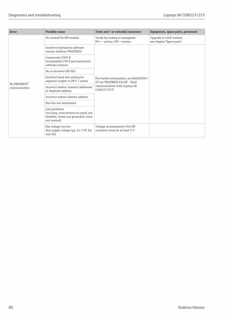
Diagnostics and troubleshooting Liquisys M CUM223/253
80 Endress+Hauser
No PROFIBUS® communication
No central PA/DP module Verify by looking at nameplate:PA = -xxx3xx /DP = xxx4xx.
Upgrade to LSCP module,see chapter "Spare parts".
Incorrect instrument software version (without PROFIBUS)
For further information, see BA00209C/07/en "PROFIBUS PA/DP - Field communication with Liquisys M CxM223/253".
Commuwin (CW) II: Incompatible CW II and instrument software versions
No or incorrect DD/DLL
Incorrect baud rate setting for segment coupler in DPV-1 server
Incorrect station (master) addressed or duplicate address
Incorrect station (slaves) address
Bus line not terminated
Line problems(too long, cross section too small; not shielded, screen not grounded, wires not twisted)
Bus voltage too low(bus supply voltage typ. 24 V DC for non-Ex)
Voltage at instrument’s PA/DP connector must be at least 9 V.
Error Possible cause Tests and / or remedial measures Equipment, spare parts, personnel
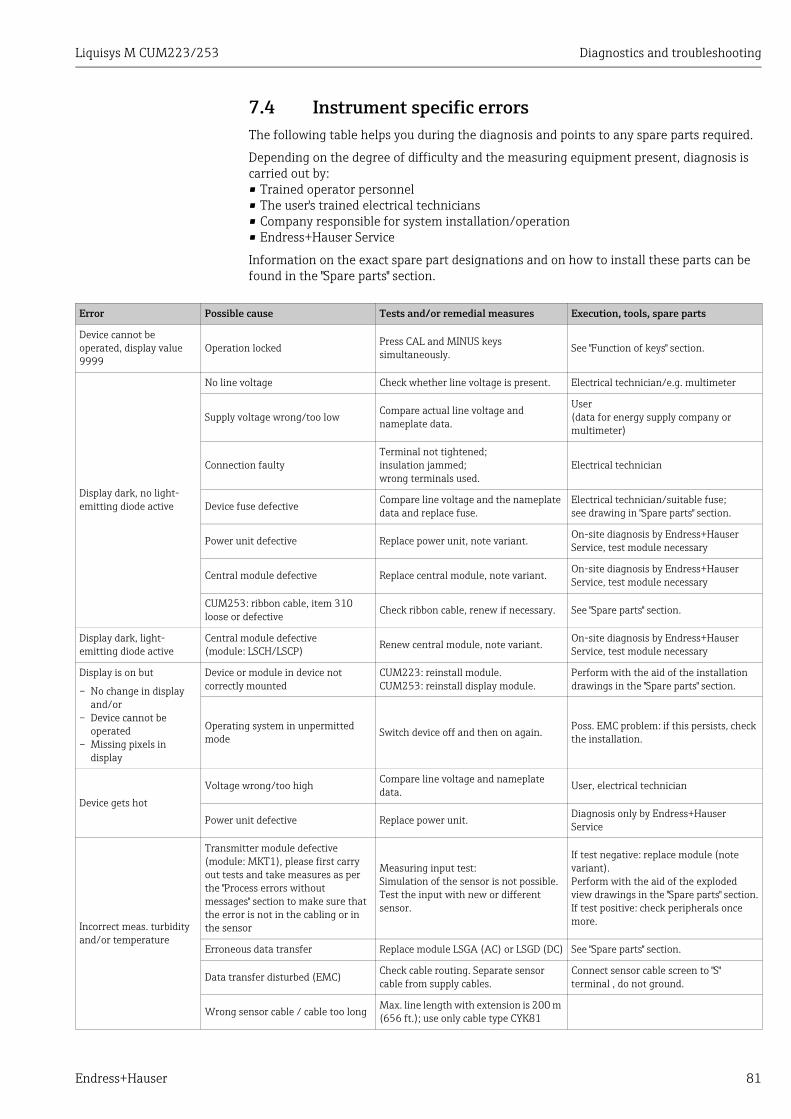
Liquisys M CUM223/253 Diagnostics and troubleshooting
Endress+Hauser 81
7.4 Instrument specific errorsThe following table helps you during the diagnosis and points to any spare parts required.
Depending on the degree of difficulty and the measuring equipment present, diagnosis is carried out by:• Trained operator personnel• The user's trained electrical technicians• Company responsible for system installation/operation• Endress+Hauser Service
Information on the exact spare part designations and on how to install these parts can be found in the "Spare parts" section.
Error Possible cause Tests and/or remedial measures Execution, tools, spare parts
Device cannot be operated, display value 9999
Operation locked Press CAL and MINUS keys simultaneously. See "Function of keys" section.
Display dark, no light-emitting diode active
No line voltage Check whether line voltage is present. Electrical technician/e.g. multimeter
Supply voltage wrong/too lowCompare actual line voltage and nameplate data.
User(data for energy supply company or multimeter)
Connection faultyTerminal not tightened; insulation jammed;wrong terminals used.
Electrical technician
Device fuse defectiveCompare line voltage and the nameplate data and replace fuse.
Electrical technician/suitable fuse;see drawing in "Spare parts" section.
Power unit defective Replace power unit, note variant. On-site diagnosis by Endress+Hauser Service, test module necessary
Central module defective Replace central module, note variant. On-site diagnosis by Endress+Hauser Service, test module necessary
CUM253: ribbon cable, item 310 loose or defective Check ribbon cable, renew if necessary. See "Spare parts" section.
Display dark, light-emitting diode active
Central module defective (module: LSCH/LSCP) Renew central module, note variant. On-site diagnosis by Endress+Hauser
Service, test module necessary
Display is on but
– No change in display and/or
– Device cannot be operated
– Missing pixels in display
Device or module in device not correctly mounted
CUM223: reinstall module.CUM253: reinstall display module.
Perform with the aid of the installation drawings in the "Spare parts" section.
Operating system in unpermitted mode Switch device off and then on again. Poss. EMC problem: if this persists, check
the installation.
Device gets hot
Voltage wrong/too highCompare line voltage and nameplate data. User, electrical technician
Power unit defective Replace power unit. Diagnosis only by Endress+Hauser Service
Incorrect meas. turbidity and/or temperature
Transmitter module defective (module: MKT1), please first carry out tests and take measures as per the "Process errors without messages" section to make sure that the error is not in the cabling or in the sensor
Measuring input test:Simulation of the sensor is not possible. Test the input with new or different sensor.
If test negative: replace module (note variant).Perform with the aid of the exploded view drawings in the "Spare parts" section.If test positive: check peripherals once more.
Erroneous data transfer Replace module LSGA (AC) or LSGD (DC) See "Spare parts" section.
Data transfer disturbed (EMC)Check cable routing. Separate sensor cable from supply cables.
Connect sensor cable screen to "S" terminal , do not ground.
Wrong sensor cable / cable too long Max. line length with extension is 200 m (656 ft.); use only cable type CYK81
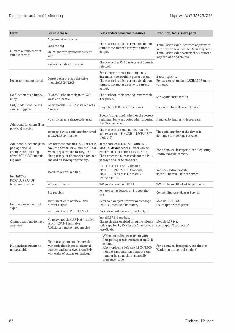
Diagnostics and troubleshooting Liquisys M CUM223/253
82 Endress+Hauser
Current output, current value incorrect
Adjustment not correctCheck with installed current simulation, connect mA meter directly to current output.
If simulation value incorrect: adjustment in factory or new module LSCxx required.If simulation value correct: check current loop for load and shunts.
Load too big
Shunt/short to ground in current loop
Incorrect mode of operation Check whether 0–20 mA or 4–20 mA is selected.
No current output signal Current output stage defective (module LSCH/LSCP)
For safety reasons, first completely disconnect the auxiliary power output.Check with installed current simulation, connect mA meter directly to current output.
If test negative:Renew central module LSCH/LSCP (note variant).
No function of additional relay
CUM253: ribbon cable item 320 loose or defective
Check ribbon cable seating, renew cable if required. See "Spare parts" section.
Only 2 additional relays can be triggered
Relay module LSR1-2 installed with 2 relays Upgrade to LSR1-4 with 4 relays. User or Endress+Hauser Service
Additional functions (Plus package) missing
No or incorrect release code usedIf retrofitting: check whether the correct serial number was quoted when ordering the Plus package.
Handled by Endress+Hauser Sales
Incorrect device serial number saved in LSCH/LSCP module
Check whether serial number on the nameplate matches SNR in LSCH/ LSCP (field S 8).
The serial number of the device is definitive for the Plus package.
Additional functions (Plus package and/or Chemoclean) missing after LSCH/LSCP module replaced
Replacement modules LSCH or LSCP have the device serial number 0000 when they leave the factory. The Plus package or Chemoclean are not enabled on leaving the factory.
In the case of LSCH/LSCP with SNR 0000, a device serial number can be entered once in fields E115 to E117.Then enter the release code for the Plus package and/or Chemoclean.
For a detailed description, see "Replacing central module" section.
No HART or PROFIBUS PA/ DP interface function
Incorrect central module
HART: LSCH-H1 or H2 module,PROFIBUS PA: LSCP-PA module,PROFIBUS DP: LSCP-DP module,see field E112.
Replace central module;user or Endress+Hauser Service.
Wrong software SW version see field E111. SW can be modified with optoscope.
Bus problem Remove some devices and repeat the test.
Contact Endress+Hauser Service.
No temperature output signal
Instrument does not have 2nd current output
Refer to nameplate for variant; change LSCH-x1 module if necessary.
Module LSCH-x2,see chapter "Spare parts".
Instrument with PROFIBUS PA PA instrument has no current output!
Chemoclean function not available
No relay module (LSR1-x) installed or only LSR1-2 availableAdditional function not enabled
Install LSR1-4 module.Chemoclean is enabled using the release code supplied by E+H in the Chemoclean retrofit kit.
Module LSR1-4,see chapter "Spare parts".
Plus package functions not available
Plus package not enabled (enable with code that depends on serial number and is received from E+H with order of extension package)
– When upgrading instrument with Plus package: code received from E+H enter.
– After replacing defective LSCH/LSCP module: first enter instrument serial number (s. nameplate) manually, then enter code.
For a detailed description, see chapter "Replacing the central module".
Error Possible cause Tests and/or remedial measures Execution, tools, spare parts
Liquisys M CUM223/253 Maintenance
Endress+Hauser 83
8 MaintenanceTake all the necessary measures in time to guarantee the operational safety and reliability of the entire measuring system.
Maintenance work at the transmitter comprises:• Calibration (see "Calibration" section)• Cleaning of assembly and sensor• Cable and connection check
When performing any work on the device, bear in mind any potential impact this may have on the process control system or on the process itself.NOTICE
Electrostatic discharge (ESD)Risk of damage to electronic components‣ Take personal protective measures to avoid ESD, such as discharging beforehand at PE or
permanent grounding with a wrist strap.‣ For your own safety, use only genuine spare parts. With genuine spare parts, the
function, accuracy and reliability are also guaranteed after repair.
8.1 Maintenance of the entire measuring point
8.1.1 Cleaning the transmitterClean the front of the housing with usual commercial cleaning agents.
In accordance with DIN 42 115, the front is resistant to:• Ethanol (short periods)• Diluted acids (max. 2% HCl)• Diluted bases (max. 3% NaOH)• Soap-based household cleaners
NOTICEProhibited cleaning agentsDamage to the housing surface or housing seal‣ For cleaning purposes, never use concentrated mineral acids or bases.‣ Never use organic cleaners such as benzyl alcohol, methanol, methylene chloride, xylene
or concentrated glycerol cleaner.‣ Never use high-pressure steam for cleaning purposes.
Maintenance Liquisys M CUM223/253
84 Endress+Hauser
8.1.2 Checking the measuring pointThe sensors CUS31 and CUS41 cannot be simulated as they contain the complete data processing and all the measured values are transmitted to CUM223/253 using the digital interface RS 485. Therefore a functional sensor is required for the measuring point test.
Method for testing a measuring point:
• Check that device is operable and that the display reacts appropriately, e.g. by pressing the PLUS key.
• Check the current outputs by carrying out a current simulation (Field O3(2)).• Measure the sensor operating voltage: approx. 10 to 16 V at terminals 87 (+) and 88 (–).• The cause for an incorrect voltage may be present either at the device or at the sensor.
– Replace the sensor.– If the sensor operating voltage is still too low replace the power supply module LSGA/
LSGD (Pos. 10/20, make sure to use the appropriate version - see spare parts).• Sensor operating voltage is o.k. but no measured turbidity value even with a new sensor.
Replace the transmitter module MKT1.
8.1.3 Replacing the sensorThe sensors CUS31/CUS41 contain their own digital signal processor and communicate with the turbidity measuring instrument via an interface RS 485. All sensor data (factory calibration data and customer calibration data) are permanently saved in the sensor.
You can find detailed information on these sensors in the:
• Operating Instructions Turbimax W CUS31 BA00176C/07/EN.• Technical Information Turbimax W CUS41 TI00177C/07/EN.
When replacing a sensor pay attention to the following:
• Replacing the sensor CUS31-xxA or CUS41All calibration data are saved in the sensor. When using the original data records (“read only”), no calibration is necessary after sensor replacement. Medium-specific calibrations must be repeated.
• Replacing the sensor CUS31-xxE or CUS31-xxSAll factory calibration data are saved in the sensor. The sensor and the assembly are calibrated together. No additional calibration is required for applications with pure or ultrapure water, if the sensor and the assembly are replaced together. The calibration data of the sensor are automatically transferred to the measuring instrument.
8.1.4 Maintenance assemblyPlease refer to the corresponding assembly Operating Instructions for information on maintaining and trouble-shooting the assembly. Here you can find a description for assembling and disassembling, sensor replacement, seal replacement, as well as information on stability and spare parts and accessories.

Liquisys M CUM223/253 Repair
Endress+Hauser 85
9 RepairSpare parts are to be ordered from your sales center responsible. Specify the order numbers listed in the chapter "Spare parts kits".
To be on the safe side, you should always specify the following data with your spare part orders:• Instrument order code (order code)• Serial number (serial no.)• Software version where available
Refer to the nameplate for the order code and serial number.The software version is displayed in the instrument sofware (see chapter "Instrument configuration") if the instrument processor system is functional.
9.1 Dismantling the panel-mounted instrumentPlease note the effects on the process if the device is taken out of service!
Please refer to the following diagram for the item numbers.
1. Disconnect the terminal block (item 426 b) from the rear of the device to de-energize the device.
2. Then remove the terminal blocks (item 426 a and item 430) from the rear of the device. Now you can disassemble the device.
3. Press in the latches of the end frame (item 340) and remove the frame from the rear.
4. Release the special screw (item 400) by turning it counter-clockwise.
5. Remove the entire electronics block from the housing. The modules are only mechanically connected and can be easily separated:– Simply remove the processor/display module from the front.– Pull out the brackets of the rear plate (item 320) slightly. – Now you can remove the side modules.
6. Remove the turbidity transmitter (item 270) as follows:– Using fine side-cutting pliers, nip off the heads of the plastic distance holders.– Then remove the module from above.
Assembly is the reverse of the disassembly sequence. Tighten the special screw hand-tight without a tool.
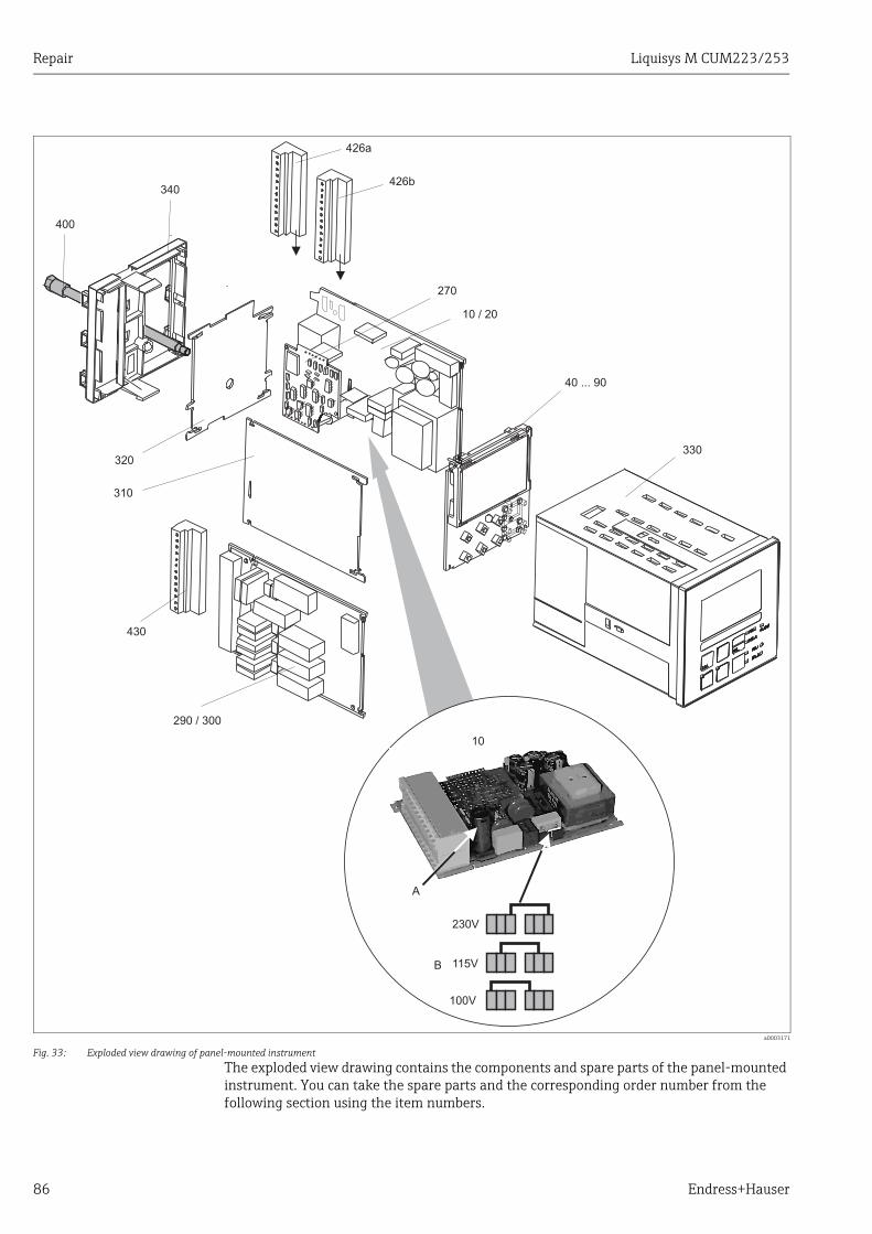
Repair Liquisys M CUM223/253
86 Endress+Hauser
The exploded view drawing contains the components and spare parts of the panel-mounted instrument. You can take the spare parts and the corresponding order number from the following section using the item numbers.
a0003171
Fig. 33: Exploded view drawing of panel-mounted instrument
230V
100V
115V
10
A
B
290 / 300
430
310
320
400
340
426a
426b
270
10 / 20
40 ... 90
330
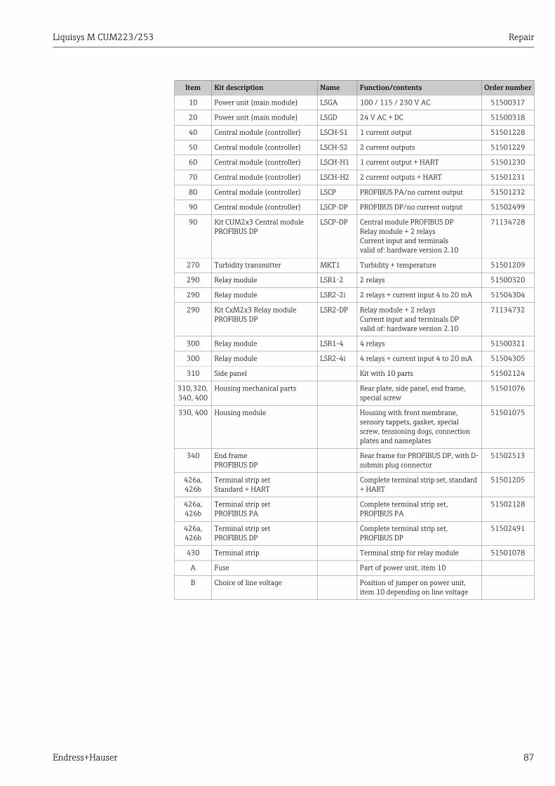
Liquisys M CUM223/253 Repair
Endress+Hauser 87
Item Kit description Name Function/contents Order number
10 Power unit (main module) LSGA 100 / 115 / 230 V AC 51500317
20 Power unit (main module) LSGD 24 V AC + DC 51500318
40 Central module (controller) LSCH-S1 1 current output 51501228
50 Central module (controller) LSCH-S2 2 current outputs 51501229
60 Central module (controller) LSCH-H1 1 current output + HART 51501230
70 Central module (controller) LSCH-H2 2 current outputs + HART 51501231
80 Central module (controller) LSCP PROFIBUS PA/no current output 51501232
90 Central module (controller) LSCP-DP PROFIBUS DP/no current output 51502499
90 Kit CUM2x3 Central module PROFIBUS DP
LSCP-DP Central module PROFIBUS DPRelay module + 2 relaysCurrent input and terminalsvalid of: hardware version 2.10
71134728
270 Turbidity transmitter MKT1 Turbidity + temperature 51501209
290 Relay module LSR1-2 2 relays 51500320
290 Relay module LSR2-2i 2 relays + current input 4 to 20 mA 51504304
290 Kit CxM2x3 Relay module PROFIBUS DP
LSR2-DP Relay module + 2 relaysCurrent input and terminals DPvalid of: hardware version 2.10
71134732
300 Relay module LSR1-4 4 relays 51500321
300 Relay module LSR2-4i 4 relays + current input 4 to 20 mA 51504305
310 Side panel Kit with 10 parts 51502124
310, 320, 340, 400
Housing mechanical parts Rear plate, side panel, end frame, special screw
51501076
330, 400 Housing module Housing with front membrane, sensory tappets, gasket, special screw, tensioning dogs, connection plates and nameplates
51501075
340 End framePROFIBUS DP
Rear frame for PROFIBUS DP, with D-submin plug connector
51502513
426a, 426b
Terminal strip setStandard + HART
Complete terminal strip set, standard + HART
51501205
426a, 426b
Terminal strip setPROFIBUS PA
Complete terminal strip set, PROFIBUS PA
51502128
426a, 426b
Terminal strip setPROFIBUS DP
Complete terminal strip set, PROFIBUS DP
51502491
430 Terminal strip Terminal strip for relay module 51501078
A Fuse Part of power unit, item 10
B Choice of line voltage Position of jumper on power unit, item 10 depending on line voltage
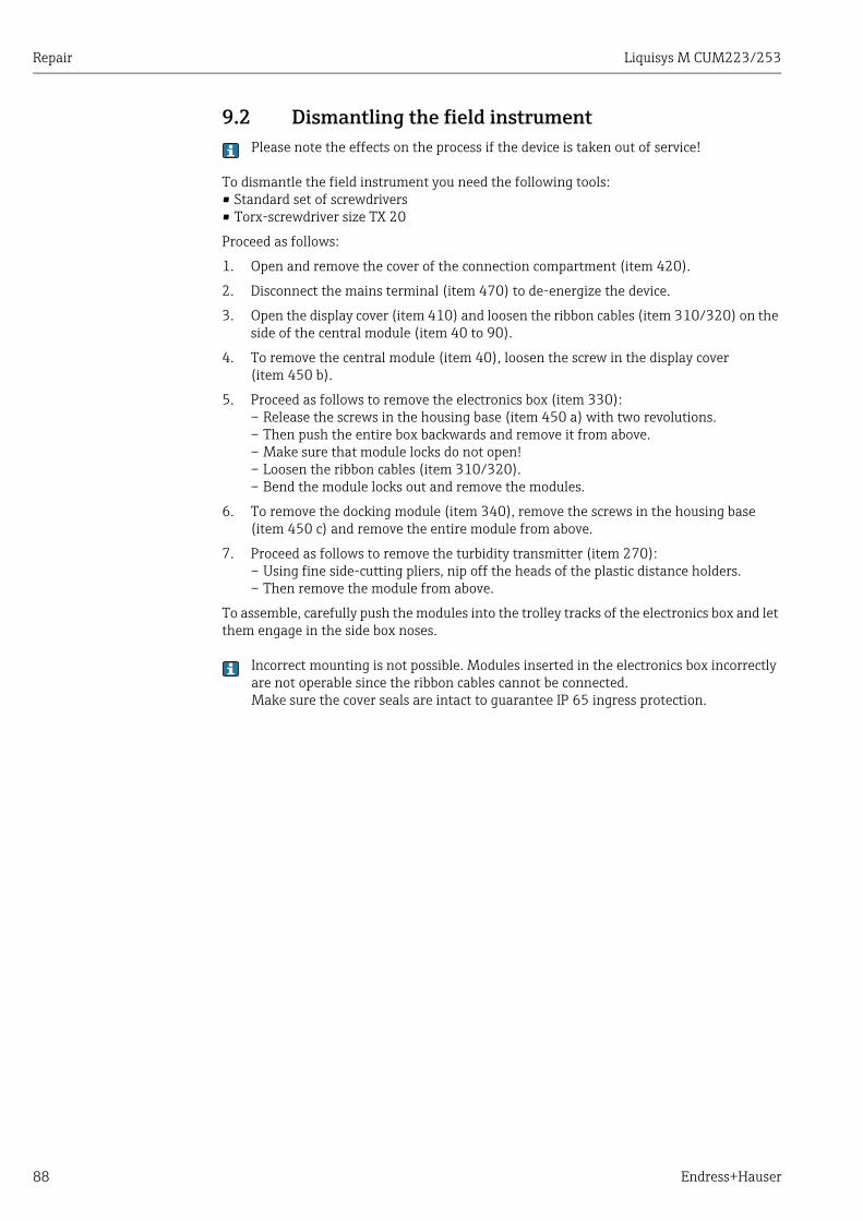
Repair Liquisys M CUM223/253
88 Endress+Hauser
9.2 Dismantling the field instrumentPlease note the effects on the process if the device is taken out of service!
To dismantle the field instrument you need the following tools:• Standard set of screwdrivers• Torx-screwdriver size TX 20
Proceed as follows:
1. Open and remove the cover of the connection compartment (item 420).
2. Disconnect the mains terminal (item 470) to de-energize the device.
3. Open the display cover (item 410) and loosen the ribbon cables (item 310/320) on the side of the central module (item 40 to 90).
4. To remove the central module (item 40), loosen the screw in the display cover (item 450 b).
5. Proceed as follows to remove the electronics box (item 330): – Release the screws in the housing base (item 450 a) with two revolutions.– Then push the entire box backwards and remove it from above.– Make sure that module locks do not open!– Loosen the ribbon cables (item 310/320).– Bend the module locks out and remove the modules.
6. To remove the docking module (item 340), remove the screws in the housing base (item 450 c) and remove the entire module from above.
7. Proceed as follows to remove the turbidity transmitter (item 270): – Using fine side-cutting pliers, nip off the heads of the plastic distance holders.– Then remove the module from above.
To assemble, carefully push the modules into the trolley tracks of the electronics box and let them engage in the side box noses.
Incorrect mounting is not possible. Modules inserted in the electronics box incorrectly are not operable since the ribbon cables cannot be connected.Make sure the cover seals are intact to guarantee IP 65 ingress protection.
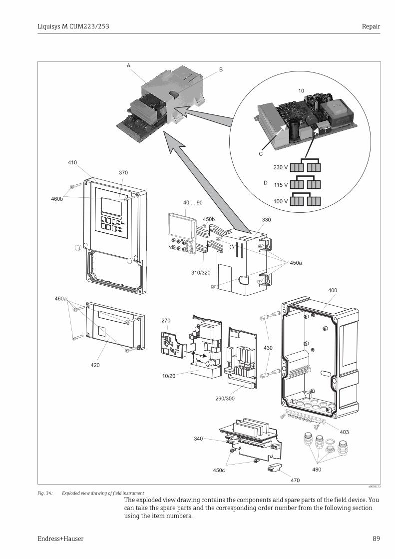
Liquisys M CUM223/253 Repair
Endress+Hauser 89
The exploded view drawing contains the components and spare parts of the field device. You can take the spare parts and the corresponding order number from the following section using the item numbers.
a0003173
Fig. 34: Exploded view drawing of field instrument
100 V
Pos. 10Netzteil 100 – 230 V AC
230 V
115 V
Sicherung
10
C
D
410
460b
460a
420
40 ... 90
310/320
270
10/20
340
450c
470
480
290/300
400
430
450a
330
370
AB
450b
403
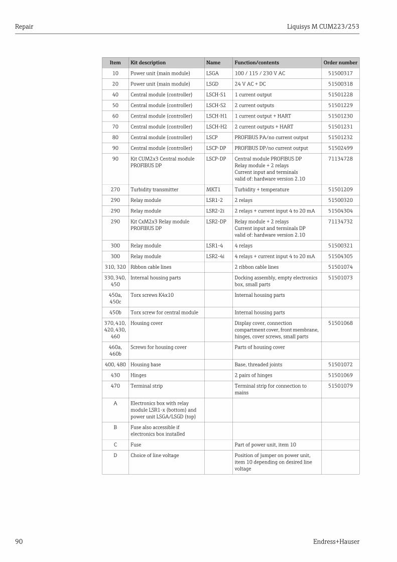
Repair Liquisys M CUM223/253
90 Endress+Hauser
Item Kit description Name Function/contents Order number
10 Power unit (main module) LSGA 100 / 115 / 230 V AC 51500317
20 Power unit (main module) LSGD 24 V AC + DC 51500318
40 Central module (controller) LSCH-S1 1 current output 51501228
50 Central module (controller) LSCH-S2 2 current outputs 51501229
60 Central module (controller) LSCH-H1 1 current output + HART 51501230
70 Central module (controller) LSCH-H2 2 current outputs + HART 51501231
80 Central module (controller) LSCP PROFIBUS PA/no current output 51501232
90 Central module (controller) LSCP-DP PROFIBUS DP/no current output 51502499
90 Kit CUM2x3 Central module PROFIBUS DP
LSCP-DP Central module PROFIBUS DPRelay module + 2 relaysCurrent input and terminalsvalid of: hardware version 2.10
71134728
270 Turbidity transmitter MKT1 Turbidity + temperature 51501209
290 Relay module LSR1-2 2 relays 51500320
290 Relay module LSR2-2i 2 relays + current input 4 to 20 mA 51504304
290 Kit CxM2x3 Relay module PROFIBUS DP
LSR2-DP Relay module + 2 relaysCurrent input and terminals DPvalid of: hardware version 2.10
71134732
300 Relay module LSR1-4 4 relays 51500321
300 Relay module LSR2-4i 4 relays + current input 4 to 20 mA 51504305
310, 320 Ribbon cable lines 2 ribbon cable lines 51501074
330, 340, 450
Internal housing parts Docking assembly, empty electronics box, small parts
51501073
450a, 450c
Torx screws K4x10 Internal housing parts
450b Torx screw for central module Internal housing parts
370, 410, 420, 430,
460
Housing cover Display cover, connection compartment cover, front membrane, hinges, cover screws, small parts
51501068
460a, 460b
Screws for housing cover Parts of housing cover
400, 480 Housing base Base, threaded joints 51501072
430 Hinges 2 pairs of hinges 51501069
470 Terminal strip Terminal strip for connection to mains
51501079
A Electronics box with relay module LSR1-x (bottom) and power unit LSGA/LSGD (top)
B Fuse also accessible if electronics box installed
C Fuse Part of power unit, item 10
D Choice of line voltage Position of jumper on power unit, item 10 depending on desired line voltage

Liquisys M CUM223/253 Repair
Endress+Hauser 91
9.3 Replacing the central moduleGenerally, when a central module has been replaced, all data which can be changed are set to the factory setting.
Proceed as described below if a central module is replaced:
1. If possible, note the customized settings of the device, such as:– Calibration data– Current assignment, main parameter and temperature– Relay function selections– Limit value/controller settings– Cleaning settings– Monitoring functions– Interface parameters
2. Disassemble the device as explained in the "Dismantling the panel-mounted instrument" or "Dismantling the field instrument" section.
3. Use the part number on the central module to check whether the new module has the same part number as the previous module.
4. Assemble the device with the new module.
5. Start up the device again and check the basic functions (e.g. measured value and temperature display, operation via keyboard).
6. Enter the serial number:– Read the serial number (“ser-no.”) on the nameplate of the device.– Enter this number in the fields E115 (year, one-digit), E116 (month, one-digit), E117
(consecutive number, four-digit).– In the field E118, the complete number is displayed again so you can check it is
correct.You can only enter the serial number for new modules with the serial number 0000. This can only be done once! For this reason, make sure the number entered is correct before you confirm with ENTER!Entry of an incorrect code will prevent the additional functions from being enabled. An incorrect serial number can only be corrected at the factory!
Press ENTER to confirm the serial number or cancel the entry to enter the number again.
7. If available, enter the release codes for the Plus Package and/or Chemoclean in the "Service" menu.
8. Check the Plus Package release (e.g. by opening the function group CHECK / Code P) or the Chemoclean function.
9. Make the customer device settings again.
Repair Liquisys M CUM223/253
92 Endress+Hauser
9.4 ReturnThe device must be returned if repairs or a factory calibration are required, or if the wrong device has been ordered or delivered. According to legal regulations, Endress+Hauser, as an ISO-certified company, is required to follow certain procedures when handling returned products that are in contact with medium.
To ensure swift, safe and professional device returns, please read the return procedures and conditions on the internet site:www.services.endress.com/return-material
9.5 DisposalThe device contains electronic components and must therefore be disposed of in accordance with regulations on the disposal of electronic waste.Please observe local regulations.

Liquisys M CUM223/253 Accessories
Endress+Hauser 93
10 Accessories
10.1 SensorsTurbimax W CUS31• Turbidity sensor for drinking water and wastewater applications, 90 ° scattered light
method• Ordering acc. to product structure, see Technical Information (TI176C/07/en)
Turbimax W CUS41• Turbidity sensor for wastewater and solid content measurements, 90 ° scattered light
method• Ordering acc. to product structure, see Technical Information (TI177C/07/en)
10.2 Connection accessoriesCYK81 measuring cable• Non-terminated cable for extending the sensor cables (e.g. Memosens)• 2x2 wires, twisted with shield and PVC sheath (2 x 2 x 0.5 mm2 + shield)• Goods sold by meter, order no.: 51502543
Junction box VBM• For cable extension• 10 terminals• Cable entries: 2 x Pg 13.5 or 2 x NPT ½"• Material: aluminum• Ingress protection: IP 65 (i NEMA 4X)• Order numbers:
– cable entries Pg 13.5: 50003987– cable entries NPT ½": 51500177
Junction box RM• For cable extension (e.g. for Memosens sensors)• 5 terminals• Cable entries: 2 x Pg 13.5• Material: PC• Ingress protection: IP 65• Order no.: 51500832
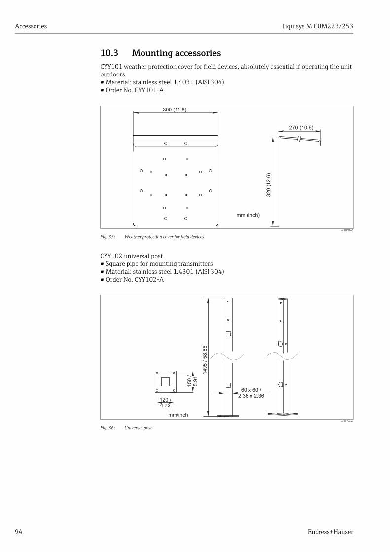
Accessories Liquisys M CUM223/253
94 Endress+Hauser
10.3 Mounting accessoriesCYY101 weather protection cover for field devices, absolutely essential if operating the unit outdoors• Material: stainless steel 1.4031 (AISI 304)• Order No. CYY101-A
a0019166
Fig. 35: Weather protection cover for field devices
CYY102 universal post • Square pipe for mounting transmitters• Material: stainless steel 1.4301 (AISI 304)• Order No. CYY102-A
a0005742
Fig. 36: Universal post
32
0 (
12
.6)
270 (10.6)
300 (11.8)
mm (inch)
14
95
/5
8.8
6
60 x 60 /2.36 x 2.36
120 /4.72
15
0/
5.9
1
mm/inch
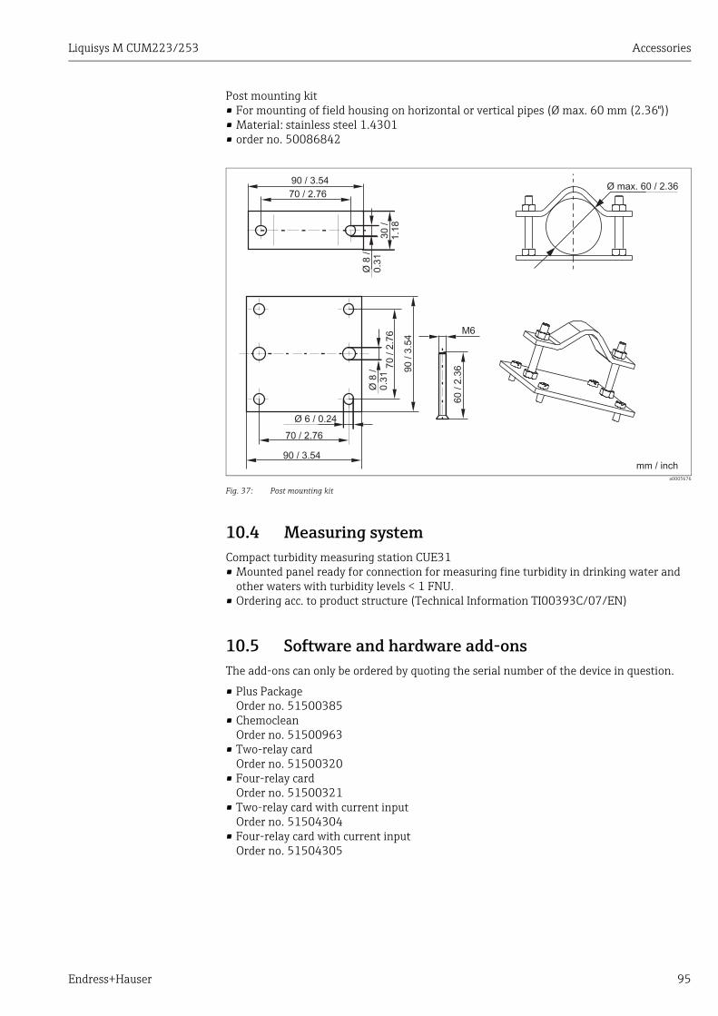
Liquisys M CUM223/253 Accessories
Endress+Hauser 95
Post mounting kit• For mounting of field housing on horizontal or vertical pipes (Ø max. 60 mm (2.36"))• Material: stainless steel 1.4301• order no. 50086842
a0005676
Fig. 37: Post mounting kit
10.4 Measuring systemCompact turbidity measuring station CUE31• Mounted panel ready for connection for measuring fine turbidity in drinking water and
other waters with turbidity levels < 1 FNU.• Ordering acc. to product structure (Technical Information TI00393C/07/EN)
10.5 Software and hardware add-onsThe add-ons can only be ordered by quoting the serial number of the device in question.
• Plus PackageOrder no. 51500385
• ChemocleanOrder no. 51500963
• Two-relay cardOrder no. 51500320
• Four-relay cardOrder no. 51500321
• Two-relay card with current inputOrder no. 51504304
• Four-relay card with current inputOrder no. 51504305
70 / 2.76
90 / 3.54
Ø 6 / 0.24
Ø8
/0
.31
70
/2.7
6
90
/3.5
4
M6
60
/2.3
6
90 / 3.54
70 / 2.76
Ø8
/0.3
130
/1.1
8
Ø max. 60 / 2.36
mm / inch
Technical data Liquisys M CUM223/253
96 Endress+Hauser
11 Technical data
11.1 Input
Measured variables Turbidity, suspended solids, temperature
Measuring range
Cable specification
Signal input Digital communication
Temperature measurement
NTC 30 k at 25 °C (77 °F)
Binary inputs
Current input 4 to 20 mA, galvanically separated
Load: 260 at 20 mA (voltage drop 5.2 V)
CUS31: 0.000 to 9999 FNU/NTU0.00 to 3000 ppm0.0 to 3.0 g/l0.0 to 200.0 %
CUS41: 0.00 to 9999 FNU/NTU0.00 to 9999 ppm 0.0 to 300.0 g/l 0.0 to 200.0 %
Temperature: -5.0 to +70.0 °C (+23 to +158 °F)
Cable length: max. 200 m (656 ft.)
Voltage: 10 to 50 VPower consumption: max. 10 mA
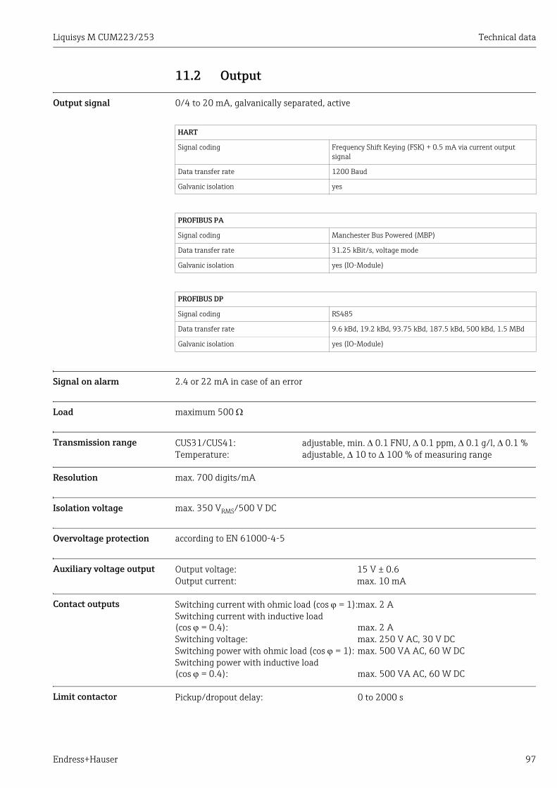
Liquisys M CUM223/253 Technical data
Endress+Hauser 97
11.2 Output
Output signal 0/4 to 20 mA, galvanically separated, active
Signal on alarm 2.4 or 22 mA in case of an error
Load maximum 500
Transmission range
Resolution max. 700 digits/mA
Isolation voltage max. 350 VRMS/500 V DC
Overvoltage protection according to EN 61000-4-5
Auxiliary voltage output
Contact outputs
Limit contactor
HART
Signal coding Frequency Shift Keying (FSK) + 0.5 mA via current output signal
Data transfer rate 1200 Baud
Galvanic isolation yes
PROFIBUS PA
Signal coding Manchester Bus Powered (MBP)
Data transfer rate 31.25 kBit/s, voltage mode
Galvanic isolation yes (IO-Module)
PROFIBUS DP
Signal coding RS485
Data transfer rate 9.6 kBd, 19.2 kBd, 93.75 kBd, 187.5 kBd, 500 kBd, 1.5 MBd
Galvanic isolation yes (IO-Module)
CUS31/CUS41: adjustable, min. 0.1 FNU, 0.1 ppm, 0.1 g/l, 0.1 %Temperature: adjustable, 10 to 100 % of measuring range
Output voltage: 15 V ± 0.6Output current: max. 10 mA
Switching current with ohmic load (cos = 1):max. 2 ASwitching current with inductive load (cos = 0.4): max. 2 ASwitching voltage: max. 250 V AC, 30 V DCSwitching power with ohmic load (cos = 1): max. 500 VA AC, 60 W DCSwitching power with inductive load (cos = 0.4): max. 500 VA AC, 60 W DC
Pickup/dropout delay: 0 to 2000 s
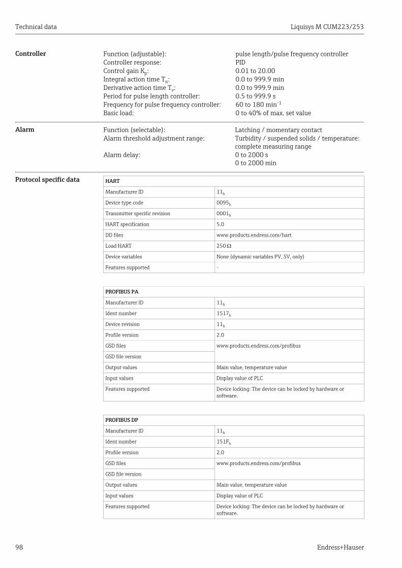
Technical data Liquisys M CUM223/253
98 Endress+Hauser
Controller
Alarm
Protocol specific data
Function (adjustable): pulse length/pulse frequency controllerController response: PIDControl gain Kp: 0.01 to 20.00Integral action time Tn: 0.0 to 999.9 minDerivative action time Tv: 0.0 to 999.9 minPeriod for pulse length controller: 0.5 to 999.9 sFrequency for pulse frequency controller: 60 to 180 min-1
Basic load: 0 to 40% of max. set value
Function (selectable): Latching / momentary contactAlarm threshold adjustment range: Turbidity / suspended solids / temperature:
complete measuring rangeAlarm delay: 0 to 2000 s
0 to 2000 min
HART
Manufacturer ID 11h
Device type code 0095h
Transmitter specific revision 0001h
HART specification 5.0
DD files www.products.endress.com/hart
Load HART 250
Device variables None (dynamic variables PV, SV, only)
Features supported -
PROFIBUS PA
Manufacturer ID 11h
Ident number 1517h
Device revision 11h
Profile version 2.0
GSD files www.products.endress.com/profibus
GSD file version
Output values Main value, temperature value
Input values Display value of PLC
Features supported Device locking: The device can be locked by hardware or software.
PROFIBUS DP
Manufacturer ID 11h
Ident number 151Fh
Profile version 2.0
GSD files www.products.endress.com/profibus
GSD file version
Output values Main value, temperature value
Input values Display value of PLC
Features supported Device locking: The device can be locked by hardware or software.
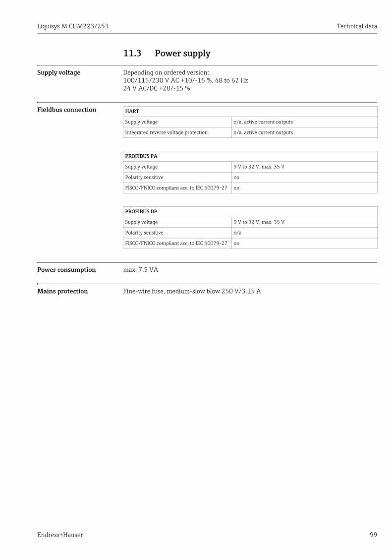
Liquisys M CUM223/253 Technical data
Endress+Hauser 99
11.3 Power supply
Supply voltage Depending on ordered version:100/115/230 V AC +10/-15 %, 48 to 62 Hz24 V AC/DC +20/-15 %
Fieldbus connection
Power consumption max. 7.5 VA
Mains protection Fine-wire fuse, medium-slow blow 250 V/3.15 A
HART
Supply voltage n/a, active current outputs
Integrated reverse voltage protection n/a, active current outputs
PROFIBUS PA
Supply voltage 9 V to 32 V, max. 35 V
Polarity sensitive no
FISCO/FNICO compliant acc. to IEC 60079-27 no
PROFIBUS DP
Supply voltage 9 V to 32 V, max. 35 V
Polarity sensitive n/a
FISCO/FNICO compliant acc. to IEC 60079-27 no
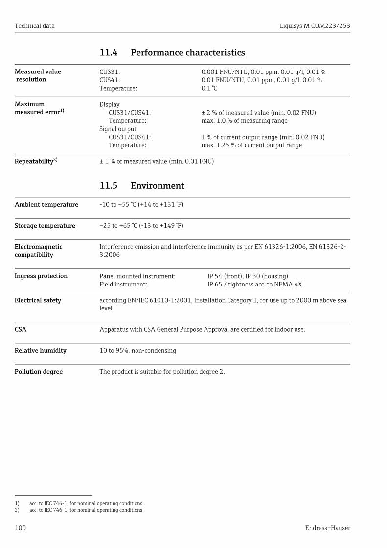
Technical data Liquisys M CUM223/253
100 Endress+Hauser
11.4 Performance characteristics
Measured valueresolution
Maximum measured error1)
Repeatability2) ± 1 % of measured value (min. 0.01 FNU)
11.5 Environment
Ambient temperature -10 to +55 °C (+14 to +131 °F)
Storage temperature –25 to +65 °C (-13 to +149 °F)
Electromagnetic compatibility
Interference emission and interference immunity as per EN 61326-1:2006, EN 61326-2-3:2006
Ingress protection
Electrical safety according EN/IEC 61010-1:2001, Installation Category II, for use up to 2000 m above sea level
CSA Apparatus with CSA General Purpose Approval are certified for indoor use.
Relative humidity 10 to 95%, non-condensing
Pollution degree The product is suitable for pollution degree 2.
CUS31: 0.001 FNU/NTU, 0.01 ppm, 0.01 g/l, 0.01 %CUS41: 0.01 FNU/NTU, 0.01 ppm, 0.01 g/l, 0.01 %Temperature: 0.1 °C
1) acc. to IEC 746-1, for nominal operating conditions
DisplayCUS31/CUS41: ± 2 % of measured value (min. 0.02 FNU)Temperature: max. 1.0 % of measuring range
Signal outputCUS31/CUS41: 1 % of current output range (min. 0.02 FNU)Temperature: max. 1.25 % of current output range
2) acc. to IEC 746-1, for nominal operating conditions
Panel mounted instrument: IP 54 (front), IP 30 (housing)Field instrument: IP 65 / tightness acc. to NEMA 4X
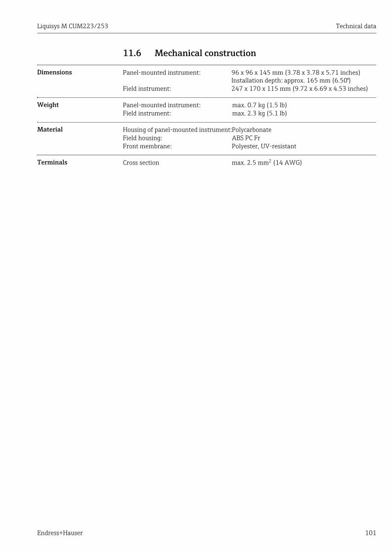
Liquisys M CUM223/253 Technical data
Endress+Hauser 101
11.6 Mechanical construction
Dimensions
Weight
Material
Terminals
Panel-mounted instrument: 96 x 96 x 145 mm (3.78 x 3.78 x 5.71 inches)Installation depth: approx. 165 mm (6.50")
Field instrument: 247 x 170 x 115 mm (9.72 x 6.69 x 4.53 inches)
Panel-mounted instrument: max. 0.7 kg (1.5 lb)Field instrument: max. 2.3 kg (5.1 lb)
Housing of panel-mounted instrument:PolycarbonateField housing: ABS PC FrFront membrane: Polyester, UV-resistant
Cross section max. 2.5 mm2 (14 AWG)
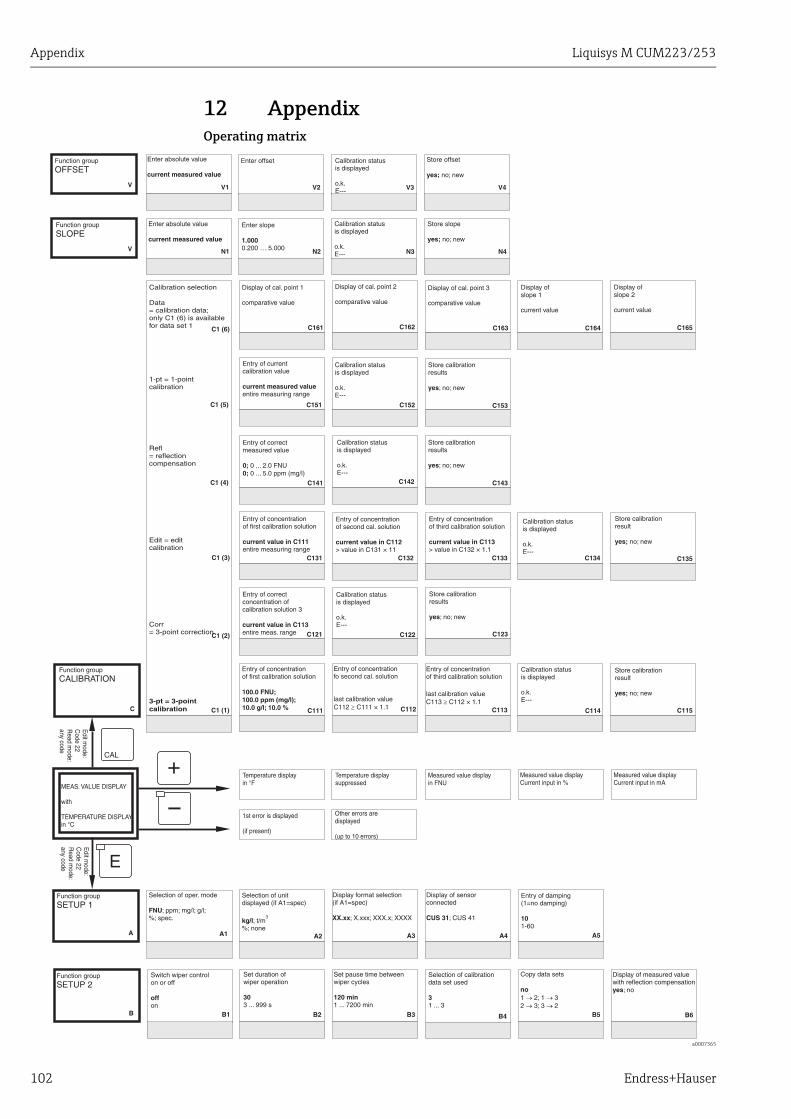
Appendix Liquisys M CUM223/253
102 Endress+Hauser
12 AppendixOperating matrix
a0007365
Enter slope
0.200 … 5.0001.000
Function group
SLOPE
V
V
V2
N2
V3
N3
Store slope
no; newyes;
V4
N4
V1
N1
C C115C111 C112 C113 C114
C1 (6)
C1 (5)
C1 (4)
C1 (3)
C1 (2)
C1 (1)
C135C132C131 C133 C134
C123C121 C122
C141 C142 C143
C153C151 C152
C161 C162 C163 C164 C165
Measured value displayCurrent input in %
Measured value displayCurrent input in mA
B B1 B2 B3 B4 B5 B6
A A1 A2 A4A3 A5
Enter offsetFunction group
OFFSET
Calibration statusis displayed
o.k.E---
Calibration statusis displayed
o.k.E---
Store offset
no; newyes;
Enter absolute value
current measured value
Enter absolute value
current measured value
Function group
CALIBRATIONStore calibrationresult
no; newyes;
Entry of concentrationof first calibration solution
100.0 FNU;100.0 ppm (mg/l);10.0 g/l; 10.0 %
.
Entry of concentrationfo second cal. solution
last calibration valueC112 C111 × 1.1³
Entry of concentrationof third calibration solution
last calibration valueC113 C112 × 1.1³
.
Calibration statusis displayed
o.k.E---
Calibration selection
Data= calibration data;only C1 (6) is availablefor data set 1
1-pt = 1-pointcalibration
Refl= reflectioncompensation
Edit = editcalibration
Corr= 3-point correction
3-pt = 3-pointcalibration
Store calibrationresult
no; newyes;
Entry of concentrationof second cal. solution
> value in C131 × 11current value in C112
Entry of concentrationof first calibration solution
entire measuring rangecurrent value in C111
Entry of concentrationof third calibration solution
> value in C132 × 1.1current value in C113
Calibration statusis displayed
o.k.E---
Store calibrationresults
; no; newyes
Entry of correctconcentration ofcalibration solution 3
entire meas. rangecurrent value in C113
Calibration statusis displayed
o.k.E---
Entry of correctmeasured value
0 ... 2.0 FNU0 ... 5.0 ppm (mg/l)
0;0;
Calibration statusis displayed
o.k.E---
Store calibrationresults
; no; newyes
Store calibrationresults
; no; newyes
Entry of currentcalibration value
entire measuring rangecurrent measured value
Calibration statusis displayed
o.k.E---
Display of cal. point 1
comparative value
Display of cal. point 2
comparative value
Display of cal. point 3
comparative value
Display ofslope 1
current value
Display ofslope 2
current value
MEAS. VALUE DISPLAY
with
TEMPERATURE DISPLAYin °C
Measured value displayin FNU
Temperature displaysuppressed
Temperature displayin °F
Other errors aredisplayed
(up to 10 errors)
1st error is displayed
(if present)
Edit m
ode:C
ode 22R
ead mode:
any code
Edit m
ode:C
ode 22R
ead mode:
any code
Function group
SETUP 2Switch wiper controlon or off
onoff
Set duration ofwiper operation
3 ... 999 s30
Set pause time betweenwiper cycles
1 ... 7200 min120 min
Selection of calibrationdata set used
1 ... 33
Copy data sets
1 2; 1 32 3; 3 2
no® ®
® ®
Display of measured valuewith reflection compensation
; noyes
Function group
SETUP 1Selection of oper. mode
; ppm; mg/l; g/l;%; spec.FNU
Selection of unitdisplayed (if A1=spec)
; t/m%; nonekg/l
3
Display of sensorconnected
; CUS 41CUS 31
Display format selection(if A1=spec)
; X.xxx; XXX.x; XXXXXX.xx
Entry of damping(1=no damping)
1-6010

Liquisys M CUM223/253 Appendix
Endress+Hauser 103
a0007366
C166
B7
Entry of gas bubblebarrier
0.1 … 100%3.0%
B8 B9
Display ofconversion factor
current value
Entry of correctprocess temperature
–5.0 ... 100.0current meas. value
°C
Entry oftemperature difference(offset)
–5.0...5.0current offset
°C
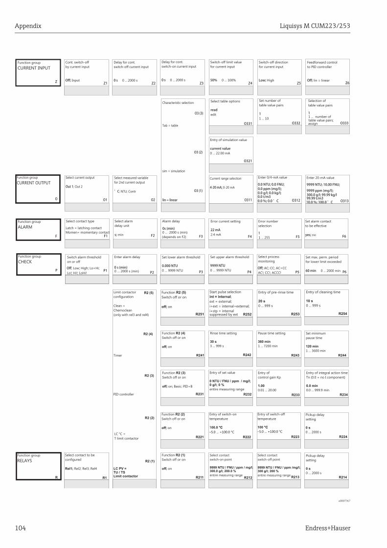
Appendix Liquisys M CUM223/253
104 Endress+Hauser
a0007367
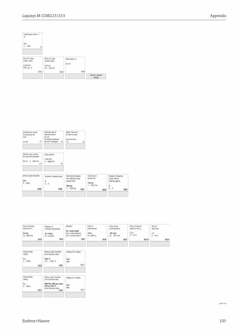
Liquisys M CUM223/253 Appendix
Endress+Hauser 105
a0007368
Field for customersettings
O335 O336O334
Entry of x value(meas. value)
0.000 NTUFNU / g/l / %
Z7
Entry of y value(current value)
0.0 ... 20.0 mA4.00 mA
Table status o.k.
noyes;
Feedforward control = 1at
0 … 100%50%
R225 R226
R235 R236 R237 R239R238
R215 R216
R255 R256 R257 R259R258
R217
Display of LC status
MINMAX
Display of LC status
MINMAX
R227
F8F7 F9
P7 P8
Enter setpoint
0 ... 9999 NTU0.000 NTU
Automatic start ofcleaning function
yes(not always displayed,see error messages)
no;
Activate error currentfor previously seterror
yesno;
Select “next error”or return to menu
Rnext=next error¬
Set max. perm. periodfor lower limit exceeded
0 ... 2000 min60 min
Entry of post-rinse time
0 ... 999 s20 s
Number of repeat cycles
0 ... 50
Set interval betweentwo cleaning cycles(pause time)
1 ... 7200 min360 min
Number of cleaningcycles withoutcleaning agents
0 ... 90
Set minimumpause time
1 ... R357 min120 min
Entry of derivateaction time Tv
0.0...999.9 min0.0 min
Selection ofcontroller characteristic
inv = inverteddir = direct
Selection
freq = pulse frequencycurr = current output 2
Ien = pulse length
Entry of max.pulse frequency
60 ... 180 1/min120 1/min
Entry ofpulse interval
0.5...999.9 s10.0 s
Dropout delaysetting
0 ... 2000 s0 s
Setting of alarm threshold(as an absolute value)
100.0 °C–5.0 ... +100.0 °C
Dropout delaysetting
0 ... 2000 s0 s
Setting of alarm threshold(as an absolute value)
entire measuring range
9999 FNU; 9999 ppm (mg/l);300.0 g/l; 200.0 %
R2311R2310
Entry ofbasic load
0 ... 40 %0 %
Entry of minimumswitch-on time t
0.1...5.0 s
ON
0.3 s
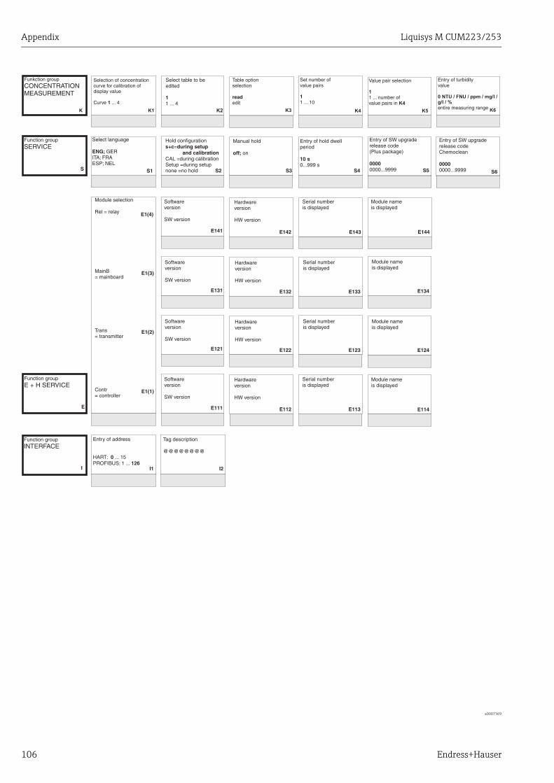
Appendix Liquisys M CUM223/253
106 Endress+Hauser
a0007369
Funkction group
CONCENTRATIONMEASUREMENT
K K1 K3 K4 K5 K6K2
Function groupSERVICE
S S1 S2 S4S3 S5 S6
E112 E113
E121 E122 E123
E131 E132 E133
E141
E111
Entry of address
HART: ... 15PROFIBUS: 1 ...
0126
I1 I2
E142 E143
Function groupE + H SERVICE
E
Function groupINTERFACE
I
E1(4)
E1(3)
E1(2)
E1(1)
E134
E144
E114
E124
Tag description
@@@@@@@@
Selection of concentrationcurve for calibration ofdisplay value
Curve ... 41
Table optionselection
editread
Set number ofvalue pairs
1 ... 101
Value pair selection
1 ... number ofvalue pairs in
1
K4
Entry of turbidityvalue
entire measuring range
0 NTU / FNU / ppm / mg/l /g/l / %
Select table to beedited
1 ... 41
Hold configuration=s+c during setup
and calibrationCAL =during calibrationSetup =during setupnone =no hold
Entry of hold dwellperiod
0...999 s10 s
Manual hold
onoff;
Entry of SW upgraderelease code(Plus package)
0000...99990000
Entry of SW upgraderelease codeChemoclean
0000...99990000
Hardwareversion
HW version
Serial numberis displayed
Softwareversion
SW version
Hardwareversion
HW version
Serial numberis displayed
Softwareversion
SW version
Hardwareversion
HW version
Serial numberis displayed
Softwareversion
SW version
Softwareversion
SW version
Hardwareversion
HW version
Serial numberis displayed
Module selection
Rel = relay
MainB= mainboard
Trans= transmitter
Contr= controller
Module nameis displayed
Module nameis displayed
Module nameis displayed
Module nameis displayed
Select language
GERITA; FRAESP; NEL
ENG;

Liquisys M CUM223/253 Appendix
Endress+Hauser 107
a0007370
K7 K8
S7 S8 S10S9
Entry of concentration
entire measuring range
Table status o.k.
noyes;
Order numberis displayed
Serial numberis displayed
Perform instrument test
Displ = display testno
Reset of instrumentto basic values
Sens = sensor data;Facty = factory settings
no

Appendix Liquisys M CUM223/253
108 Endress+Hauser
Liquisys M CUM223/253
Endress+Hauser 109
Index
AAccess codes . . . . . . . . . . . . . . . . . . . . . . . . . . . . . . . . . . . . 27Accessories . . . . . . . . . . . . . . . . . . . . . . . . . . . . . . . . . . . . . 93Alarm . . . . . . . . . . . . . . . . . . . . . . . . . . . . . . . . . . . . . . . . . 98Alarm contact. . . . . . . . . . . . . . . . . . . . . . . . . . . . . . . . . . . 21Ambient temperature . . . . . . . . . . . . . . . . . . . . . . . . . . . 100Appendix
Operating matrix . . . . . . . . . . . . . . . . . . . . . . . . . . . . 102Automatic mode . . . . . . . . . . . . . . . . . . . . . . . . . . . . . . . . 26Auxiliary voltage output . . . . . . . . . . . . . . . . . . . . . . . . . . 97
BBinary inputs . . . . . . . . . . . . . . . . . . . . . . . . . . . . . . . . . . . 96
CCable specification . . . . . . . . . . . . . . . . . . . . . . . . . . . . . . . 96Calibration . . . . . . . . . . . . . . . . . . . . . . . . . . . . . . . . . . 64–72CE mark. . . . . . . . . . . . . . . . . . . . . . . . . . . . . . . . . . . . . . . . . . 8Central module. . . . . . . . . . . . . . . . . . . . . . . . . . . . . . . . . . 91Check. . . . . . . . . . . . . . . . . . . . . . . . . . . . . . . . . . . . . . . . . . 45Checking
Connections . . . . . . . . . . . . . . . . . . . . . . . . . . . . . . . . . 21Function . . . . . . . . . . . . . . . . . . . . . . . . . . . . . . . . . . . . 29Installation . . . . . . . . . . . . . . . . . . . . . . . . . . . . . . . . . . 15
Checking the measuring point . . . . . . . . . . . . . . . . . . . . . 84Chemoclean function . . . . . . . . . . . . . . . . . . . . . . . . . . . . 53Cleaning
Transmitter. . . . . . . . . . . . . . . . . . . . . . . . . . . . . . . . . . 83Commissioning . . . . . . . . . . . . . . . . . . . . . . . . . . . . . . . . . 29Communication . . . . . . . . . . . . . . . . . . . . . . . . . . . . . . . . . 63Connection diagram . . . . . . . . . . . . . . . . . . . . . . . . . . . . . 17Contact outputs . . . . . . . . . . . . . . . . . . . . . . . . . . . . . . . . . 97Controller . . . . . . . . . . . . . . . . . . . . . . . . . . . . . . . . . . . . . . 98CSA . . . . . . . . . . . . . . . . . . . . . . . . . . . . . . . . . . . . . . . . . . 100CSA general purpose . . . . . . . . . . . . . . . . . . . . . . . . . . . . . . . 8Current . . . . . . . . . . . . . . . . . . . . . . . . . . . . . . . . . . . . . . . . 96Current input . . . . . . . . . . . . . . . . . . . . . . . . . . . . . . . . . . . 37Current outputs . . . . . . . . . . . . . . . . . . . . . . . . . . . . . . . . . 40
DDeclaration of conformity. . . . . . . . . . . . . . . . . . . . . . . . . . . 8Designated use . . . . . . . . . . . . . . . . . . . . . . . . . . . . . . . . . . . . 5Diagnosis code . . . . . . . . . . . . . . . . . . . . . . . . . . . . . . . . . . 75Diagnostics . . . . . . . . . . . . . . . . . . . . . . . . . . . . . . . . . . . . . 75Dimensions. . . . . . . . . . . . . . . . . . . . . . . . . . . . . . . . . . . . 101Dismantling
Field instrument. . . . . . . . . . . . . . . . . . . . . . . . . . . . . . 88Panel-mounted instrument . . . . . . . . . . . . . . . . . . . . 85
Display. . . . . . . . . . . . . . . . . . . . . . . . . . . . . . . . . . . . . . . . . 22Disposal. . . . . . . . . . . . . . . . . . . . . . . . . . . . . . . . . . . . . . . . 92
EE+H Service . . . . . . . . . . . . . . . . . . . . . . . . . . . . . . . . . . . . . 62Electrical safety . . . . . . . . . . . . . . . . . . . . . . . . . . . . . . . . 100Electrical connection
Without Memosens . . . . . . . . . . . . . . . . . . . . . . . . . . . 16Electrical icons . . . . . . . . . . . . . . . . . . . . . . . . . . . . . . . . . . . . 6Electrical symbols . . . . . . . . . . . . . . . . . . . . . . . . . . . . . . . . . 6Electromagnetic compatibility . . . . . . . . . . . . . . . . . . . . . . . 5EMC. . . . . . . . . . . . . . . . . . . . . . . . . . . . . . . . . . . . . . . . . . 100Environment . . . . . . . . . . . . . . . . . . . . . . . . . . . . . . . . . . 100
FFactory settings . . . . . . . . . . . . . . . . . . . . . . . . . . . . . . . . . . 30Field device connection . . . . . . . . . . . . . . . . . . . . . . . . . . . 18Fieldbus connection . . . . . . . . . . . . . . . . . . . . . . . . . . . . . . 99Freezing of outputs . . . . . . . . . . . . . . . . . . . . . . . . . . . . . . . 28
HHold function . . . . . . . . . . . . . . . . . . . . . . . . . . . . . . . . 28, 61
IIcons
Electrical . . . . . . . . . . . . . . . . . . . . . . . . . . . . . . . . . . . . . . 6Incoming acceptance. . . . . . . . . . . . . . . . . . . . . . . . . . . . . . . 7Ingress protection . . . . . . . . . . . . . . . . . . . . . . . . . . . . . . 100Input . . . . . . . . . . . . . . . . . . . . . . . . . . . . . . . . . . . . . . . . . . . 96Installation . . . . . . . . . . . . . . . . . . . . . . . . . . . . . . . . 9–10, 12Instrument specific errors . . . . . . . . . . . . . . . . . . . . . . . . . 81Interfaces . . . . . . . . . . . . . . . . . . . . . . . . . . . . . . . . . . . . . . . 63Isolation voltage . . . . . . . . . . . . . . . . . . . . . . . . . . . . . . . . . 97
KKey assignment . . . . . . . . . . . . . . . . . . . . . . . . . . . . . . . . . . 24
LLimit . . . . . . . . . . . . . . . . . . . . . . . . . . . . . . . . . . . . . . . . . . . 97Limit contactor . . . . . . . . . . . . . . . . . . . . . . . . . . . . . . . . . . 48Load . . . . . . . . . . . . . . . . . . . . . . . . . . . . . . . . . . . . . . . . . . . 97
Liquisys M CUM223/253
110 Endress+Hauser
MMains protection. . . . . . . . . . . . . . . . . . . . . . . . . . . . . . . . . 99Maintenance . . . . . . . . . . . . . . . . . . . . . . . . . . . . . . . . . . . . 83
Assembly . . . . . . . . . . . . . . . . . . . . . . . . . . . . . . . . . . . . 84Entire measuring point . . . . . . . . . . . . . . . . . . . . . . . . 83
Manual mode . . . . . . . . . . . . . . . . . . . . . . . . . . . . . . . . . . . 26Material . . . . . . . . . . . . . . . . . . . . . . . . . . . . . . . . . . . . . . . 101Maximum measured error. . . . . . . . . . . . . . . . . . . . . . . . 100Measured . . . . . . . . . . . . . . . . . . . . . . . . . . . . . . . . . . 96, 100Measuring range. . . . . . . . . . . . . . . . . . . . . . . . . . . . . . . . . 96Measuring cable
Variant 1 . . . . . . . . . . . . . . . . . . . . . . . . . . . . . . . . . . . . 19Measuring system. . . . . . . . . . . . . . . . . . . . . . . . . . . . . . . . . 9Mechanical construction . . . . . . . . . . . . . . . . . . . . . . . . . 101Menu
Concentration . . . . . . . . . . . . . . . . . . . . . . . . . . . . . . . . 59Current input . . . . . . . . . . . . . . . . . . . . . . . . . . . . . . . . . 37Current outputs . . . . . . . . . . . . . . . . . . . . . . . . . . . . . . . 40E+H Service . . . . . . . . . . . . . . . . . . . . . . . . . . . . . . . . . . 62Interfaces . . . . . . . . . . . . . . . . . . . . . . . . . . . . . . . . . . . . 63Monitoring functions . . . . . . . . . . . . . . . . . . . . . . . . . . 44Relay . . . . . . . . . . . . . . . . . . . . . . . . . . . . . . . . . . . . . . . . 53Service . . . . . . . . . . . . . . . . . . . . . . . . . . . . . . . . . . . . . . 61Setup 1 . . . . . . . . . . . . . . . . . . . . . . . . . . . . . . . . . . . . . . 34Setup 2 . . . . . . . . . . . . . . . . . . . . . . . . . . . . . . . . . . . . . . 35
Menu structure . . . . . . . . . . . . . . . . . . . . . . . . . . . . . . . . . . 28Monitoring functions . . . . . . . . . . . . . . . . . . . . . . . . . . . . . 44
NNameplate . . . . . . . . . . . . . . . . . . . . . . . . . . . . . . . . . . . . . . . 8
OOperating elements . . . . . . . . . . . . . . . . . . . . . . . . . . . . . . 23Operating matrix. . . . . . . . . . . . . . . . . . . . . . . . . . . . . . . . 102Operating modes. . . . . . . . . . . . . . . . . . . . . . . . . . . . . . . . . 27Operation
Display . . . . . . . . . . . . . . . . . . . . . . . . . . . . . . . . . . . . . . 22Operating concept. . . . . . . . . . . . . . . . . . . . . . . . . . . . . 26Operating elements . . . . . . . . . . . . . . . . . . . . . . . . . . . 23
Operational safety . . . . . . . . . . . . . . . . . . . . . . . . . . . . . . . . 5Output . . . . . . . . . . . . . . . . . . . . . . . . . . . . . . . . . . . . . 97–98Overvoltage protection. . . . . . . . . . . . . . . . . . . . . . . . . . . . 97
PP controller . . . . . . . . . . . . . . . . . . . . . . . . . . . . . . . . . . . . . 49PD controller . . . . . . . . . . . . . . . . . . . . . . . . . . . . . . . . . . . . 49Performance characteristics . . . . . . . . . . . . . . . . . . . . . . 100PI controller . . . . . . . . . . . . . . . . . . . . . . . . . . . . . . . . . . . . . 49PID controller . . . . . . . . . . . . . . . . . . . . . . . . . . . . . . . . . . . 49Pollution degree . . . . . . . . . . . . . . . . . . . . . . . . . . . . . . . . 100Post mounting. . . . . . . . . . . . . . . . . . . . . . . . . . . . . . . . . . . 13Power consumption . . . . . . . . . . . . . . . . . . . . . . . . . . . . . . 99Power supply . . . . . . . . . . . . . . . . . . . . . . . . . . . . . . . . . . . . 99Process specific errors . . . . . . . . . . . . . . . . . . . . . . . . . . . . 78Product identification. . . . . . . . . . . . . . . . . . . . . . . . . . . . . . 8Product safety . . . . . . . . . . . . . . . . . . . . . . . . . . . . . . . . . . . . 6Protocol specific data . . . . . . . . . . . . . . . . . . . . . . . . . . . . . 98
QQuick commissioning . . . . . . . . . . . . . . . . . . . . . . . . . . . . . 31Quick setup . . . . . . . . . . . . . . . . . . . . . . . . . . . . . . . . . . . . . 31Quick start-up . . . . . . . . . . . . . . . . . . . . . . . . . . . . . . . 22, 31
RRelative humidity . . . . . . . . . . . . . . . . . . . . . . . . . . . . . . 100Relay contact configuration . . . . . . . . . . . . . . . . . . . . . . . . 48Repair . . . . . . . . . . . . . . . . . . . . . . . . . . . . . . . . . . . . . . . . . . 85Repeatability . . . . . . . . . . . . . . . . . . . . . . . . . . . . . . . . . . 100Replacing the central module . . . . . . . . . . . . . . . . . . . . . . 91Replacing the sensor. . . . . . . . . . . . . . . . . . . . . . . . . . . . . . 84Requirements for the personnel . . . . . . . . . . . . . . . . . . . . . 5Residual concrete water . . . . . . . . . . . . . . . . . . . . . . . . . . . 67Resolution . . . . . . . . . . . . . . . . . . . . . . . . . . . . . . . . . . . . . . 97Return. . . . . . . . . . . . . . . . . . . . . . . . . . . . . . . . . . . . . . . . . . 92
SScope of delivery . . . . . . . . . . . . . . . . . . . . . . . . . . . . . . . . . . 7Sensor replacement . . . . . . . . . . . . . . . . . . . . . . . . . . . . . . 84Service. . . . . . . . . . . . . . . . . . . . . . . . . . . . . . . . . . . . . . . . . . 61Setup 1 (oxygen) . . . . . . . . . . . . . . . . . . . . . . . . . . . . . . . . . 34Setup 2 (salinity and temperature). . . . . . . . . . . . . . . . . . 35Signal . . . . . . . . . . . . . . . . . . . . . . . . . . . . . . . . . . . . . . 96–97Storage . . . . . . . . . . . . . . . . . . . . . . . . . . . . . . . . . . . . . . . 100Supply voltage . . . . . . . . . . . . . . . . . . . . . . . . . . . . . . . . . . . 99Switching on . . . . . . . . . . . . . . . . . . . . . . . . . . . . . . . . . . . . 29System configuration . . . . . . . . . . . . . . . . . . 34–63, 73–74System error messages . . . . . . . . . . . . . . . . . . . . . . . . . . . . 75
TTechnical data . . . . . . . . . . . . . . . . . . . . . . . . . . . . . . 96–101Temperature measurement . . . . . . . . . . . . . . . . . . . . . . . . 96Terminals . . . . . . . . . . . . . . . . . . . . . . . . . . . . . . . . . . . . . 101Timer for cleaning function . . . . . . . . . . . . . . . . . . . . . . . . 52Transmission range . . . . . . . . . . . . . . . . . . . . . . . . . . . . . . 97Troubleshooting . . . . . . . . . . . . . . . . . . . . . . . . . . . . . . . . . 75
Instrument scpecific errors. . . . . . . . . . . . . . . . . . . . . . 81Process scpecific errors . . . . . . . . . . . . . . . . . . . . . . . . . 78System error messages . . . . . . . . . . . . . . . . . . . . . . . . . 75
UUse
Designated . . . . . . . . . . . . . . . . . . . . . . . . . . . . . . . . . . . . 5
WWall mounting . . . . . . . . . . . . . . . . . . . . . . . . . . . . . . . . . . 12Weight . . . . . . . . . . . . . . . . . . . . . . . . . . . . . . . . . . . . . . . 101Wiring. . . . . . . . . . . . . . . . . . . . . . . . . . . . . . . . . . . . . . . . . . 16Workplace safety. . . . . . . . . . . . . . . . . . . . . . . . . . . . . . . . . . 5

Liquisys M CUM223/253
Endress+Hauser 111

www.addresses.endress.com
71212639