Embed Size (px)
Citation preview
TI347F/00/en
Technical Information
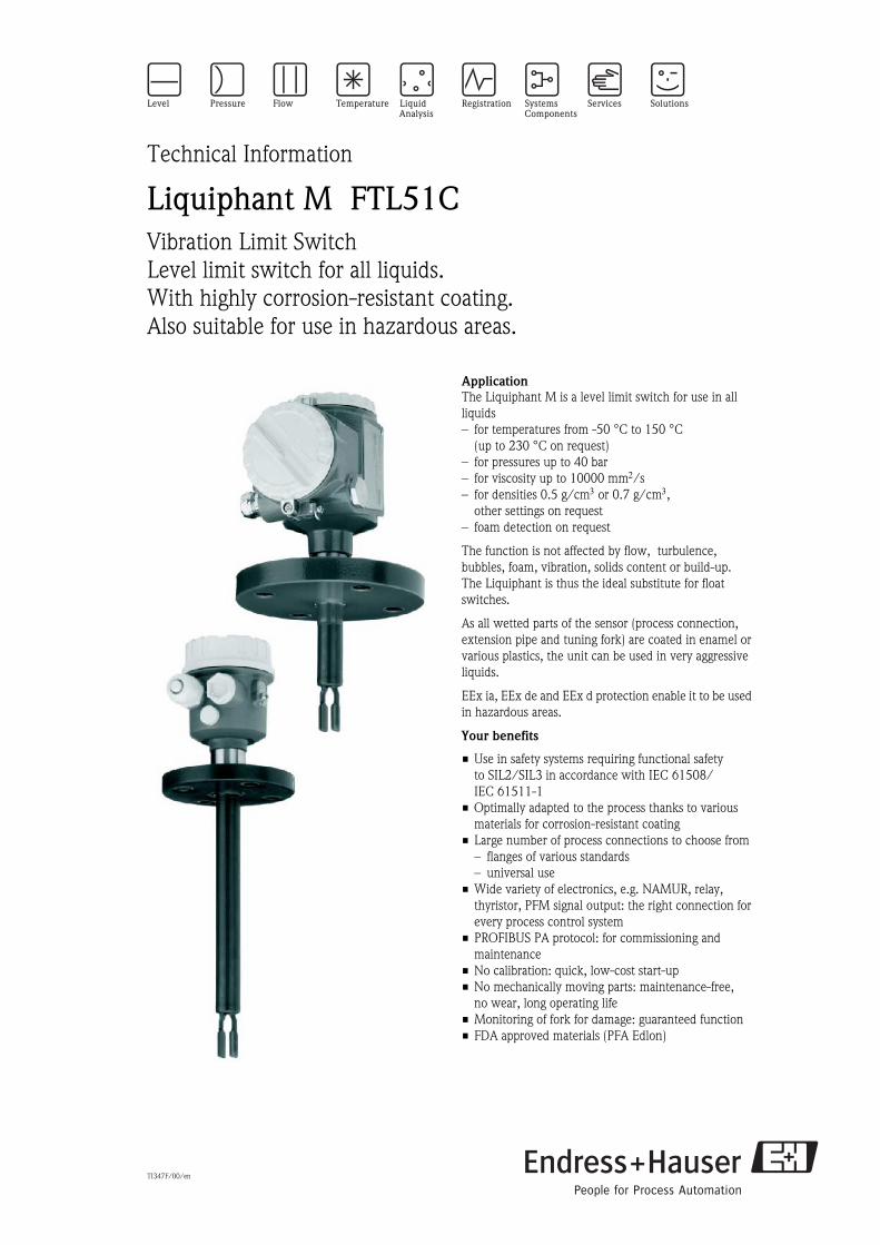
Liquiphant M FTL51CVibration Limit SwitchLevel limit switch for all liquids. With highly corrosion-resistant coating. Also suitable for use in hazardous areas.
ApplicationThe Liquiphant M is a level limit switch for use in all liquids– for temperatures from -50 °C to 150 °C
(up to 230 °C on request)– for pressures up to 40 bar– for viscosity up to 10000 mm2/s– for densities 0.5 g/cm3 or 0.7 g/cm3,
other settings on request– foam detection on request
The function is not affected by flow, turbulence, bubbles, foam, vibration, solids content or build-up. The Liquiphant is thus the ideal substitute for float switches.
As all wetted parts of the sensor (process connection, extension pipe and tuning fork) are coated in enamel or various plastics, the unit can be used in very aggressive liquids.
EEx ia, EEx de and EEx d protection enable it to be used in hazardous areas.
Your benefits
• Use in safety systems requiring functional safety to SIL2/SIL3 in accordance with IEC 61508/IEC 61511-1
• Optimally adapted to the process thanks to various materials for corrosion-resistant coating
• Large number of process connections to choose from– flanges of various standards– universal use
• Wide variety of electronics, e.g. NAMUR, relay, thyristor, PFM signal output: the right connection for every process control system
• PROFIBUS PA protocol: for commissioning and maintenance
• No calibration: quick, low-cost start-up• No mechanically moving parts: maintenance-free,
no wear, long operating life• Monitoring of fork for damage: guaranteed function• FDA approved materials (PFA Edlon)
Liquiphant M FTL51C
2 Endress+Hauser
Table of contents
Application . . . . . . . . . . . . . . . . . . . . . . . . . . . . . . . . . 4Level limit detection . . . . . . . . . . . . . . . . . . . . . . . . . . . . . . . . . . . 4
Function and system design. . . . . . . . . . . . . . . . . . . . . 4Measuring principle . . . . . . . . . . . . . . . . . . . . . . . . . . . . . . . . . . . 4Modularity . . . . . . . . . . . . . . . . . . . . . . . . . . . . . . . . . . . . . . . . . . 4Electronic versions for level limit switches . . . . . . . . . . . . . . . . . . 5Electronic versions for level sensor . . . . . . . . . . . . . . . . . . . . . . . . 5Galvanic isolation . . . . . . . . . . . . . . . . . . . . . . . . . . . . . . . . . . . . . 5Design . . . . . . . . . . . . . . . . . . . . . . . . . . . . . . . . . . . . . . . . . . . . . 5
Input . . . . . . . . . . . . . . . . . . . . . . . . . . . . . . . . . . . . . . 5Measured variable . . . . . . . . . . . . . . . . . . . . . . . . . . . . . . . . . . . . 5Measuring range (detection range) . . . . . . . . . . . . . . . . . . . . . . . . 5Product density . . . . . . . . . . . . . . . . . . . . . . . . . . . . . . . . . . . . . . 5
Electronic insert FEL51 (AC 2-wire) . . . . . . . . . . . . . . . . . . . . . . . . . . . . . . . . . 6Power supply . . . . . . . . . . . . . . . . . . . . . . . . . . . . . . . . . . . . . . . . 6Electrical connection . . . . . . . . . . . . . . . . . . . . . . . . . . . . . . . . . . 6Output signal . . . . . . . . . . . . . . . . . . . . . . . . . . . . . . . . . . . . . . . . 6Signal on alarm . . . . . . . . . . . . . . . . . . . . . . . . . . . . . . . . . . . . . . 6Connectable load . . . . . . . . . . . . . . . . . . . . . . . . . . . . . . . . . . . . . 6
Electronic insert FEL52 (DC PNP) . . . . . . . . . . . . . . . . . . . . . . . . . . . . . . . . . . . 7Power supply . . . . . . . . . . . . . . . . . . . . . . . . . . . . . . . . . . . . . . . . 7Electrical connection . . . . . . . . . . . . . . . . . . . . . . . . . . . . . . . . . . 7Output signal . . . . . . . . . . . . . . . . . . . . . . . . . . . . . . . . . . . . . . . . 7Signal on alarm . . . . . . . . . . . . . . . . . . . . . . . . . . . . . . . . . . . . . . 7Connectable load . . . . . . . . . . . . . . . . . . . . . . . . . . . . . . . . . . . . . 7
Electronic insert FEL54 (AC/DC with relay output) . . . . . . . . . . . . . . . . . . . . . 8Power supply . . . . . . . . . . . . . . . . . . . . . . . . . . . . . . . . . . . . . . . . 8Electrical connection . . . . . . . . . . . . . . . . . . . . . . . . . . . . . . . . . . 8Output signal . . . . . . . . . . . . . . . . . . . . . . . . . . . . . . . . . . . . . . . . 8Signal on alarm . . . . . . . . . . . . . . . . . . . . . . . . . . . . . . . . . . . . . . 8Connectable load . . . . . . . . . . . . . . . . . . . . . . . . . . . . . . . . . . . . . 8
Electronic insert FEL55 (8/16 mA) . . . . . . . . . . . . . . . . . . . . . . . . . . . . . . . . . . 9Power supply . . . . . . . . . . . . . . . . . . . . . . . . . . . . . . . . . . . . . . . . 9Electrical connection . . . . . . . . . . . . . . . . . . . . . . . . . . . . . . . . . . 9Output signal . . . . . . . . . . . . . . . . . . . . . . . . . . . . . . . . . . . . . . . . 9Signal on alarm . . . . . . . . . . . . . . . . . . . . . . . . . . . . . . . . . . . . . . 9Connectable load . . . . . . . . . . . . . . . . . . . . . . . . . . . . . . . . . . . . . 9
Electronic insert FEL56 (NAMUR L-H edge) . . . . . . . . . . . . . . . . . . . . . . . . . . 10Power supply . . . . . . . . . . . . . . . . . . . . . . . . . . . . . . . . . . . . . . . 10Electrical connection . . . . . . . . . . . . . . . . . . . . . . . . . . . . . . . . . 10Output signal . . . . . . . . . . . . . . . . . . . . . . . . . . . . . . . . . . . . . . . 10Signal on alarm . . . . . . . . . . . . . . . . . . . . . . . . . . . . . . . . . . . . . 10Connectable load . . . . . . . . . . . . . . . . . . . . . . . . . . . . . . . . . . . . 10
Electronic insert FEL58 (NAMUR H-L edge) . . . . . . . . . . . . . . . . . . . . . . . . . . 11Power supply . . . . . . . . . . . . . . . . . . . . . . . . . . . . . . . . . . . . . . . 11Electrical connection . . . . . . . . . . . . . . . . . . . . . . . . . . . . . . . . . 11Output signal . . . . . . . . . . . . . . . . . . . . . . . . . . . . . . . . . . . . . . . 11Signal on alarm . . . . . . . . . . . . . . . . . . . . . . . . . . . . . . . . . . . . . 11Connectable load . . . . . . . . . . . . . . . . . . . . . . . . . . . . . . . . . . . . 11
Electronic insert FEL57 (PFM). . . . . . . . . . . . . . . . . . . . . . . . . . . . . . . . . . . . . 12Power supply . . . . . . . . . . . . . . . . . . . . . . . . . . . . . . . . . . . . . . . 12Electrical connection . . . . . . . . . . . . . . . . . . . . . . . . . . . . . . . . . 12Output signal . . . . . . . . . . . . . . . . . . . . . . . . . . . . . . . . . . . . . . . 13Signal on alarm . . . . . . . . . . . . . . . . . . . . . . . . . . . . . . . . . . . . . 13Connectable load . . . . . . . . . . . . . . . . . . . . . . . . . . . . . . . . . . . . 13
Electronic insert FEL50A (PROFIBUS PA) . . . . . . . . . . . . . . . . . . . . . . . . . . . . . 14Electrical connection . . . . . . . . . . . . . . . . . . . . . . . . . . . . . . . . . 14Output signal . . . . . . . . . . . . . . . . . . . . . . . . . . . . . . . . . . . . . . . 15Signal on alarm . . . . . . . . . . . . . . . . . . . . . . . . . . . . . . . . . . . . . 15
Connection and function . . . . . . . . . . . . . . . . . . . . . . 16Connecting cables . . . . . . . . . . . . . . . . . . . . . . . . . . . . . . . . . . . 16Safety mode . . . . . . . . . . . . . . . . . . . . . . . . . . . . . . . . . . . . . . . . 16Switching time . . . . . . . . . . . . . . . . . . . . . . . . . . . . . . . . . . . . . . 16Switch-on behaviour . . . . . . . . . . . . . . . . . . . . . . . . . . . . . . . . . 16
Performance characteristics. . . . . . . . . . . . . . . . . . . . 16Reference operating conditions . . . . . . . . . . . . . . . . . . . . . . . . . . 16Maximum measured error . . . . . . . . . . . . . . . . . . . . . . . . . . . . . 16Repeatability . . . . . . . . . . . . . . . . . . . . . . . . . . . . . . . . . . . . . . . 16Hysteresis . . . . . . . . . . . . . . . . . . . . . . . . . . . . . . . . . . . . . . . . . 16Influence of medium temperature . . . . . . . . . . . . . . . . . . . . . . . 16Influence of product density . . . . . . . . . . . . . . . . . . . . . . . . . . . . 16Influence of medium pressure . . . . . . . . . . . . . . . . . . . . . . . . . . 16
Operating conditions . . . . . . . . . . . . . . . . . . . . . . . . . 17
Installation. . . . . . . . . . . . . . . . . . . . . . . . . . . . . . . . . 17Installation instructions . . . . . . . . . . . . . . . . . . . . . . . . . . . . . . . 17Examples of mounting with regard to the viscosity ν of the liquid and the tendency to form build-up . . . . . . . . . . . . . 18Orientation . . . . . . . . . . . . . . . . . . . . . . . . . . . . . . . . . . . . . . . . 19
Environment . . . . . . . . . . . . . . . . . . . . . . . . . . . . . . . 20Ambient temperature range . . . . . . . . . . . . . . . . . . . . . . . . . . . . 20Ambient temperature limits . . . . . . . . . . . . . . . . . . . . . . . . . . . . 20Storage temperature . . . . . . . . . . . . . . . . . . . . . . . . . . . . . . . . . . 20Climate class . . . . . . . . . . . . . . . . . . . . . . . . . . . . . . . . . . . . . . . 20Degree of protection . . . . . . . . . . . . . . . . . . . . . . . . . . . . . . . . . 20Vibration resistance . . . . . . . . . . . . . . . . . . . . . . . . . . . . . . . . . . 20Electromagnetic compatibility . . . . . . . . . . . . . . . . . . . . . . . . . . 20
Medium conditions . . . . . . . . . . . . . . . . . . . . . . . . . . 21Medium temperature range . . . . . . . . . . . . . . . . . . . . . . . . . . . . 21
3 Endress+Hauser
Liquiphant M FTL51C
Thermal shock . . . . . . . . . . . . . . . . . . . . . . . . . . . . . . . . . . . . . . 21Medium pressure pe . . . . . . . . . . . . . . . . . . . . . . . . . . . . . . . . . 21Test pressure . . . . . . . . . . . . . . . . . . . . . . . . . . . . . . . . . . . . . . . 21Pressure shock . . . . . . . . . . . . . . . . . . . . . . . . . . . . . . . . . . . . . 21State of aggregation . . . . . . . . . . . . . . . . . . . . . . . . . . . . . . . . . . 21Density . . . . . . . . . . . . . . . . . . . . . . . . . . . . . . . . . . . . . . . . . . . 21Viscosity . . . . . . . . . . . . . . . . . . . . . . . . . . . . . . . . . . . . . . . . . . 21Solids content . . . . . . . . . . . . . . . . . . . . . . . . . . . . . . . . . . . . . . 21
Mechanical construction . . . . . . . . . . . . . . . . . . . . . . 22Design . . . . . . . . . . . . . . . . . . . . . . . . . . . . . . . . . . . . . . . . . . . . 22Dimensions (in mm) . . . . . . . . . . . . . . . . . . . . . . . . . . . . . . . . . 23Weights . . . . . . . . . . . . . . . . . . . . . . . . . . . . . . . . . . . . . . . . . . . 24Material . . . . . . . . . . . . . . . . . . . . . . . . . . . . . . . . . . . . . . . . . . . 25Coating . . . . . . . . . . . . . . . . . . . . . . . . . . . . . . . . . . . . . . . . . . . 25Process connections . . . . . . . . . . . . . . . . . . . . . . . . . . . . . . . . . . 25
Human interface . . . . . . . . . . . . . . . . . . . . . . . . . . . . 25Electronic inserts . . . . . . . . . . . . . . . . . . . . . . . . . . . . . . . . . . . . 25Operating concept . . . . . . . . . . . . . . . . . . . . . . . . . . . . . . . . . . . 26
Certificates and approvals . . . . . . . . . . . . . . . . . . . . . 26Certificates . . . . . . . . . . . . . . . . . . . . . . . . . . . . . . . . . . . . . . . . 26Combinations of coatings, housings and electronic inserts . . . . . . 26
Ordering information . . . . . . . . . . . . . . . . . . . . . . . . 28Liquiphant M FTL51C product structure . . . . . . . . . . . . . . . . . . 28
Accessories . . . . . . . . . . . . . . . . . . . . . . . . . . . . . . . . 31Cover with sight glass . . . . . . . . . . . . . . . . . . . . . . . . . . . . . . . . 31Cover with clear screen . . . . . . . . . . . . . . . . . . . . . . . . . . . . . . . 31
Supplementary Documentation . . . . . . . . . . . . . . . . . 31Operating Instruction . . . . . . . . . . . . . . . . . . . . . . . . . . . . . . . . . 31Technical Information . . . . . . . . . . . . . . . . . . . . . . . . . . . . . . . . 31Funktionale Sicherheit (SIL) . . . . . . . . . . . . . . . . . . . . . . . . . . . . 32Safety Instructions (ATEX) . . . . . . . . . . . . . . . . . . . . . . . . . . . . . 32System Information . . . . . . . . . . . . . . . . . . . . . . . . . . . . . . . . . . 32
Liquiphant M FTL51C
4 Endress+Hauser
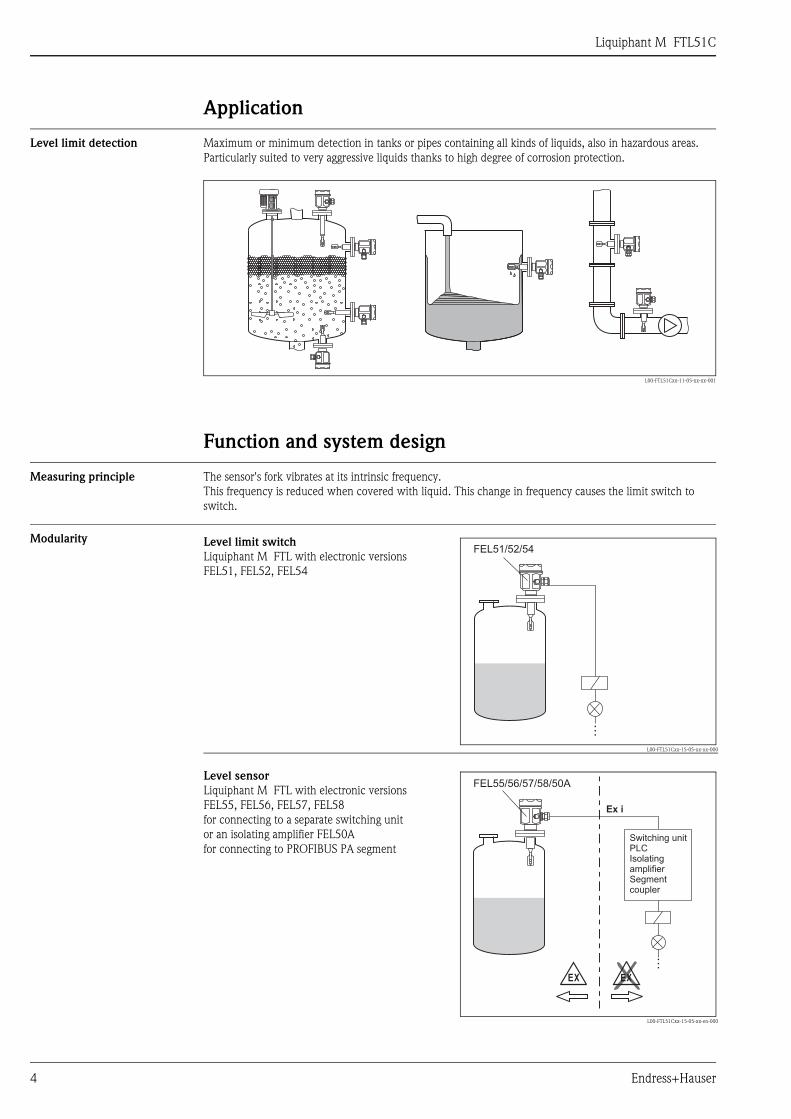
Application
Level limit detection Maximum or minimum detection in tanks or pipes containing all kinds of liquids, also in hazardous areas. Particularly suited to very aggressive liquids thanks to high degree of corrosion protection.
L00-FTL51Cxx-11-05-xx-xx-001
Function and system design
Measuring principle The sensor's fork vibrates at its intrinsic frequency. This frequency is reduced when covered with liquid. This change in frequency causes the limit switch to switch.
Modularity Level limit switchLiquiphant M FTL with electronic versionsFEL51, FEL52, FEL54
L00-FTL51Cxx-15-05-xx-xx-000
Level sensorLiquiphant M FTL with electronic versionsFEL55, FEL56, FEL57, FEL58for connecting to a separate switching unit or an isolating amplifier FEL50Afor connecting to PROFIBUS PA segment
L00-FTL51Cxx-15-05-xx-en-000
FEL51/52/54
…
FEL55/56/57/58/50A
Ex i
…
EX EX
Switching unitPLCIsolatingamplifierSegmentcoupler
Liquiphant M FTL51C
Endress+Hauser 5
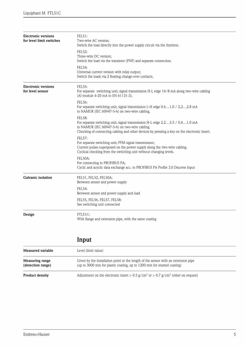
Electronic versions for level limit switches
FEL51:Two-wire AC version; Switch the load directly into the power supply circuit via the thyristor.
FEL52: Three-wire DC version; Switch the load via the transistor (PNP) and separate connection.
FEL54: Universal current version with relay output; Switch the loads via 2 floating change-over contacts.
Electronic versions for level sensor
FEL55: For separate switching unit; signal transmission H-L edge 16/8 mA along two-wire cabling(AI module 4-20 mA to EN 61131-2).
FEL56: For separate switching unit; signal transmission L-H edge 0.6…1.0 / 2.2…2.8 mA to NAMUR (IEC 60947-5-6) on two-wire cabling.
FEL58: For separate switching unit; signal transmission H-L edge 2.2…3.5 / 0.6…1.0 mA to NAMUR (IEC 60947-5-6) on two-wire cabling.Checking of connecting cabling and other devices by pressing a key on the electronic insert.
FEL57: For separate switching unit; PFM signal transmission; Current pulses superposed on the power supply along the two-wire cabling. Cyclical checking from the switching unit without changing levels.
FEL50A: For connecting to PROFIBUS PA; Cyclic and acyclic data exchange acc. to PROFIBUS PA Profile 3.0 Discrete Input
Galvanic isolation FEL51, FEL52, FEL50A: Between sensor and power supply
FEL54: Between sensor and power supply and load
FEL55, FEL56, FEL57, FEL58: See switching unit connected
Design FTL51C: With flange and extension pipe, with the same coating
Input
Measured variable Level (limit value)
Measuring range (detection range)
Given by the installation point or the length of the sensor with an extension pipe (up to 3000 mm for plastic coating, up to 1200 mm for enamel coating)
Product density Adjustment on the electronic insert > 0.5 g/cm3 or > 0.7 g/cm3 (other on request)
Liquiphant M FTL51C
6 Endress+Hauser
Electronic insert FEL51 (AC 2-wire)
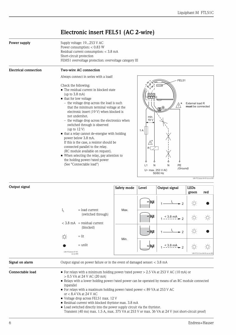
Power supply Supply voltage: 19...253 V ACPower consumption: < 0.83 WResidual current consumption: < 3.8 mAShort-circuit protectionFEM51 overvoltage protection: overvoltage category III
Electrical connection Two-wire AC connection
Output signal
Signal on alarm Output signal on power failure or in the event of damaged sensor: < 3.8 mA
Connectable load • For relays with a minimum holding power/rated power > 2.5 VA at 253 V AC (10 mA) or > 0.5 VA at 24 V AC (20 mA)
• Relays with a lower holding power/rated power can be operated by means of an RC module connected inparallel
• For relays with a maximum holding power/rated power < 89 VA at 253 V ACor < 8.4 VA at 24 V AC
• Voltage drop across FEL51 max. 12 V• Residual current with blocked thyristor max. 3.8 mA• Load switched directly into the power supply circuit via the thyristor.
Transient (40 ms) max. 1.5 A, max. 375 VA at 253 V or max. 36 VA at 24 V (not short-circuit proof)
Always connect in series with a load!
Check the following:• The residual current in blocked state
(up to 3.8 mA)• that for low voltage
– the voltage drop across the load is suchthat the minimum terminal voltage at the electronic insert (19 V) when blocked is not undershot.
– the voltage drop across the electronics when switched through is observed (up to 12 V)
• that a relay cannot de-energise with holding power below 3.8 mA.If this is the case, a resistor should be connected parallel to the relay.(RC module available on request).
• When selecting the relay, pay attention to the holding power/rated power (See "Connectable load")
L00-FTL5xxxx-04-05-xx-en-007
L1
U~ max. 253 V AC50/60 Hz
N N PE(Ground)
1 A
min.19 V
1 2
FEL51
*
R
*
External load Rbe connectedmust
Safety mode Level Output signal LEDs green red
IL
< 3.8 mA
L00-FTL2xxxx-07-05-xx-xx-000
= load current (switched through)
= residual current (blocked)
= lit
= unlit
L00-FTL51Cxx-04-05-xx-xx-001
Max.
Min.
1 2
1 2
1 2
1 2
IL
IL
< 3.8 mA
< 3.8 mA
Liquiphant M FTL51C
Endress+Hauser 7
Electronic insert FEL52 (DC PNP)
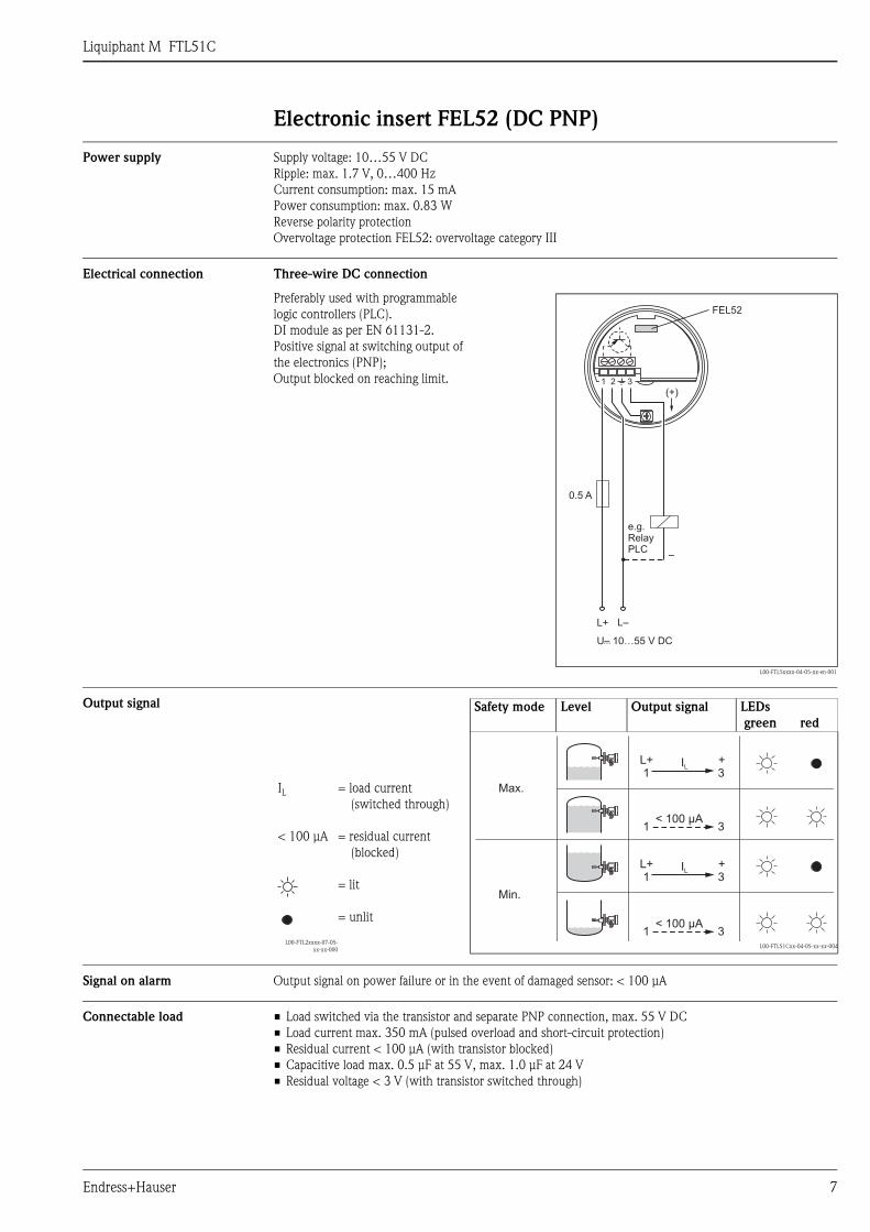
Power supply Supply voltage: 10…55 V DCRipple: max. 1.7 V, 0…400 HzCurrent consumption: max. 15 mAPower consumption: max. 0.83 WReverse polarity protectionOvervoltage protection FEL52: overvoltage category III
Electrical connection Three-wire DC connection
Output signal
Signal on alarm Output signal on power failure or in the event of damaged sensor: < 100 µA
Connectable load • Load switched via the transistor and separate PNP connection, max. 55 V DC• Load current max. 350 mA (pulsed overload and short-circuit protection)• Residual current < 100 µA (with transistor blocked)• Capacitive load max. 0.5 µF at 55 V, max. 1.0 µF at 24 V• Residual voltage < 3 V (with transistor switched through)
Preferably used with programmable logic controllers (PLC).DI module as per EN 61131-2.Positive signal at switching output of the electronics (PNP);Output blocked on reaching limit.
L00-FTL5xxxx-04-05-xx-en-001
1 2 3
(+)
FEL52
L+ L–
–
0.5 A
U– 10…55 V DC...
e.g.RelayPLC
Safety mode Level Output signal LEDs green red
IL
< 100 µA
L00-FTL2xxxx-07-05-xx-xx-000
= load current (switched through)
= residual current (blocked)
= lit
= unlit
L00-FTL51Cxx-04-05-xx-xx-004
Max.
Min.
L+ +1 3
L+ +1 3
1 3
1 3
IL
IL
< 100 µA
< 100 µA
Liquiphant M FTL51C
8 Endress+Hauser
Electronic insert FEL54 (AC/DC with relay output)
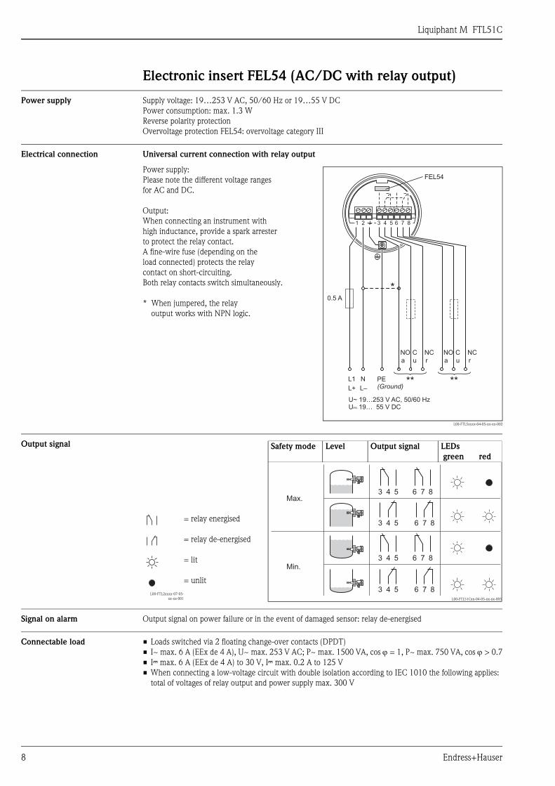
Power supply Supply voltage: 19…253 V AC, 50/60 Hz or 19…55 V DCPower consumption: max. 1.3 WReverse polarity protectionOvervoltage protection FEL54: overvoltage category III
Electrical connection Universal current connection with relay output
Output signal
Signal on alarm Output signal on power failure or in the event of damaged sensor: relay de-energised
Connectable load • Loads switched via 2 floating change-over contacts (DPDT)• I~ max. 6 A (EEx de 4 A), U~ max. 253 V AC; P~ max. 1500 VA, cos ϕ = 1, P~ max. 750 VA, cos ϕ > 0.7• I% max. 6 A (EEx de 4 A) to 30 V, I% max. 0.2 A to 125 V• When connecting a low-voltage circuit with double isolation according to IEC 1010 the following applies:
total of voltages of relay output and power supply max. 300 V
Power supply: Please note the different voltage rangesfor AC and DC.
Output:When connecting an instrument with high inductance, provide a spark arrester to protect the relay contact. A fine-wire fuse (depending on the load connected) protects the relaycontact on short-circuiting.Both relay contacts switch simultaneously.
* When jumpered, the relayoutput works with NPN logic.
L00-FTL5xxxx-04-05-xx-xx-002
L1
L+
a
NO
a
NO
u
C
u
C
N
L–
r
NC
r
NC
0.5 A
PE(Ground)
*
** **
1 2 6 7 83 4 5
FEL54
U~ 19…253 V AC, 50/60 HzU– 19… 55 V DC...
Safety mode Level Output signal LEDs green red
L00-FTL2xxxx-07-05-xx-xx-001
= relay energised
= relay de-energised
= lit
= unlit
L00-FTL51Cxx-04-05-xx-xx-005
Max.
Min.
3 54
3 54
6 87
6 87
3 54
3 54
6 87
6 87
Liquiphant M FTL51C
Endress+Hauser 9
Electronic insert FEL55 (8/16 mA)
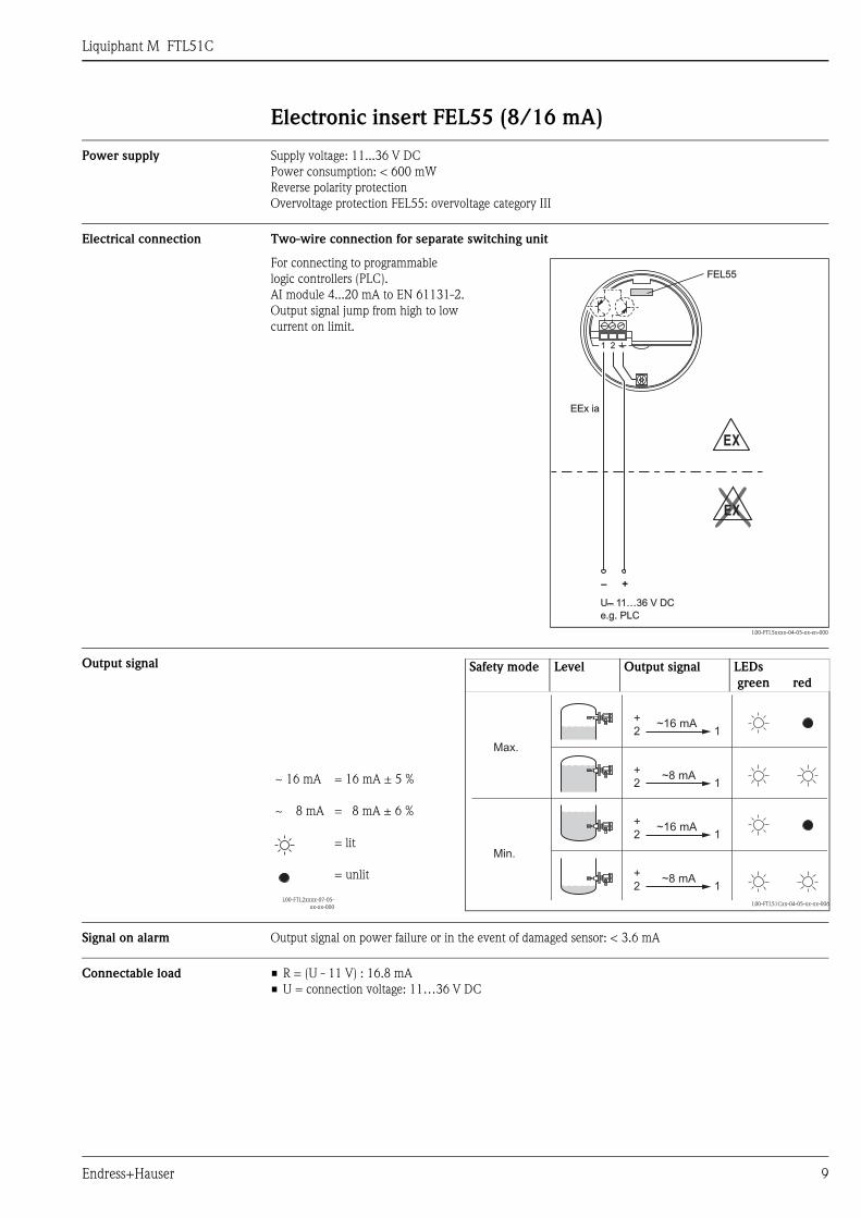
Power supply Supply voltage: 11...36 V DCPower consumption: < 600 mWReverse polarity protectionOvervoltage protection FEL55: overvoltage category III
Electrical connection Two-wire connection for separate switching unit
Output signal
Signal on alarm Output signal on power failure or in the event of damaged sensor: < 3.6 mA
Connectable load • R = (U - 11 V) : 16.8 mA• U = connection voltage: 11…36 V DC
For connecting to programmablelogic controllers (PLC).AI module 4...20 mA to EN 61131-2.Output signal jump from high to lowcurrent on limit.
L00-FTL5xxxx-04-05-xx-en-000
1 21 2
FEL55FEL55
––
EEx iaEEx ia
++
EEXX
EEXX
U– 1U– 11…36 V DC1…36 V DC......
e.g. PLCe.g. PLC
Safety mode Level Output signal LEDs green red
~ 16 mA
~ 8 mA
L00-FTL2xxxx-07-05-xx-xx-000
= 16 mA ± 5 %
= 8 mA ± 6 %
= lit
= unlit
L00-FTL51Cxx-04-05-xx-xx-006
Max.
Min.
+2 1
+2 1
+2 1
+2 1
~16 mA
~8 mA
~8 mA
~16 mA
Liquiphant M FTL51C
10 Endress+Hauser
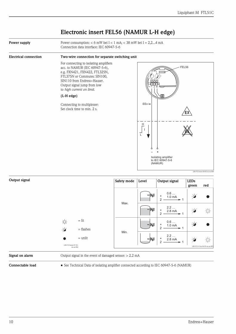
Electronic insert FEL56 (NAMUR L-H edge)
Power supply Power consumption: < 6 mW bei I < 1 mA; < 38 mW bei I = 2,2...4 mAConnection data interface: IEC 60947-5-6
Electrical connection Two-wire connection for separate switching unit
Output signal
Signal on alarm Output signal in the event of damaged sensor: > 2.2 mA
Connectable load • See Technical Data of isolating amplifier connected according to IEC 60947-5-6 (NAMUR)
For connecting to isolating amplifiersacc. to NAMUR (IEC 60947-5-6),e.g. FXN421, FXN422, FTL325N, FTL375N or Commutec SIN100, SIN110 from Endress+Hauser.Output signal jump from lowto high current on limit.
(L-H edge)
Connecting to multiplexer: Set clock time to min. 2 s.
L00-FTL5xxxx-04-05-xx-en-004
1 2
FEL56
–
EEx ia
H
L
+
EX
EXI
Isolating amplifierto(NAMUR)
IEC 60947-5-6
Safety mode Level Output signal LEDs green red
L00-FTL5xxxx-07-05-xx-xx-002
= lit
= flashes
= unlit
L00-FTL51Cxx-04-05-xx-xx-003
Max.
Min.
+2 1
+2 1
+2 1
+2 1
0.6 …1.0 mA
0.6 …1.0 mA
2.2 …2.8 mA
2.2 …2.8 mA
Liquiphant M FTL51C
Endress+Hauser 11
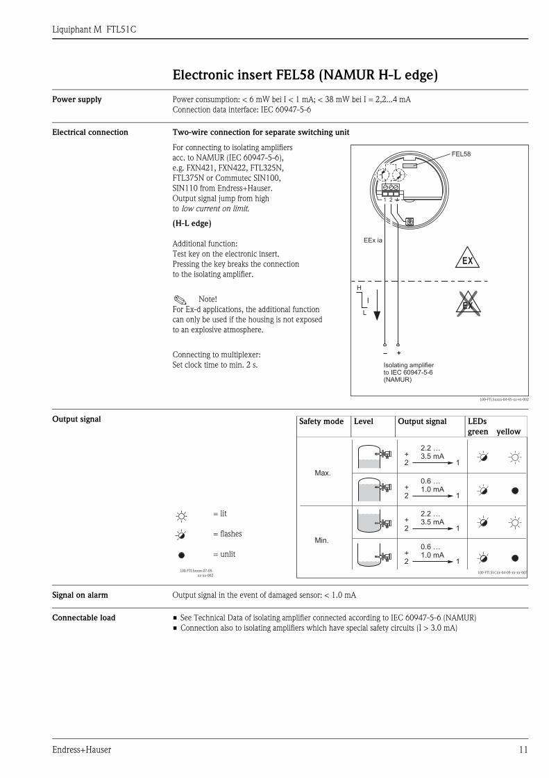
Electronic insert FEL58 (NAMUR H-L edge)
Power supply Power consumption: < 6 mW bei I < 1 mA; < 38 mW bei I = 2,2...4 mAConnection data interface: IEC 60947-5-6
Electrical connection Two-wire connection for separate switching unit
Output signal
Signal on alarm Output signal in the event of damaged sensor: < 1.0 mA
Connectable load • See Technical Data of isolating amplifier connected according to IEC 60947-5-6 (NAMUR)• Connection also to isolating amplifiers which have special safety circuits (I > 3.0 mA)
For connecting to isolating amplifiers acc. to NAMUR (IEC 60947-5-6), e.g. FXN421, FXN422, FTL325N, FTL375N or Commutec SIN100, SIN110 from Endress+Hauser.Output signal jump from high to low current on limit.
(H-L edge)
Additional function: Test key on the electronic insert.Pressing the key breaks the connection to the isolating amplifier.
! Note! For Ex-d applications, the additional function can only be used if the housing is not exposedto an explosive atmosphere.
Connecting to multiplexer:Set clock time to min. 2 s.
L00-FTL5xxxx-04-05-xx-en-002
1 2
FEL58
–
EEx ia
H
L
+
EX
EXI
Isolating amplifierto(NAMUR)
IEC 60947-5-6
Safety mode Level Output signal LEDsgreen yellow
L00-FTL5xxxx-07-05-xx-xx-002
= lit
= flashes
= unlit
L00-FTL51Cxx-04-05-xx-xx-007
Max.
Min.
+2 1
+2 1
+2 1
+2 1
2.2 …3.5 mA
2.2 …3.5 mA
0.6 …1.0 mA
0.6 …1.0 mA
Liquiphant M FTL51C
12 Endress+Hauser
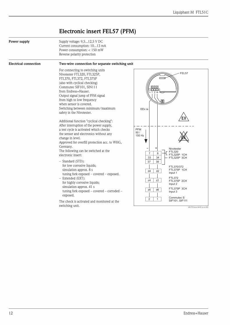
Electronic insert FEL57 (PFM)
Power supply Supply voltage: 9,5...12,5 V DCCurrent consumption: 10...13 mAPower consumption: < 150 mWReverse polarity protection
Electrical connection Two-wire connection for separate switching unit
For connecting to switching units Nivotester FTL320, FTL325P, FTL370, FTL372, FTL375P (also with cyclical checking)Commutec SIF101, SIN111from Endress+Hauser.Output signal jump of PFM signalfrom high to low frequency when sensor is covered. Switching between minimum/maximumsafety in the Nivotester.
Additional function "cyclical checking":After interruption of the power supply,a test cycle is activated which checksthe sensor and electronics without any change in level.Approved for overfill protection acc. to WHG, Germany.The following can be switched at the electronic insert:
– Standard (STD): for low corrosive liquids; simulation approx. 8 stuning fork exposed – covered – exposed.
– Extended (EXT):for highly corrosive liquids;simulation approx. 41 stuning fork exposed – covered – corroded – exposed.
The check is activated and monitored at the switching unit. L00-FTL5xxxx-04-05-xx-en-003
– +
7 8
33 34
37 38
d4 d2
z6 d6
z4 z2
2 1
PFM50 /150 Hz
EX
EX
1 2
FEL57
EEx ia
NivotesterFTL320FTL325P 1CHFTL325P 3CH
FTL370/372FTL375P 1CHInput 1
FTL372FTL375P 2CHInput 2
FTL375P 3CHInput 3
Commutec SSIF101, SIF111
Liquiphant M FTL51C
Endress+Hauser 13
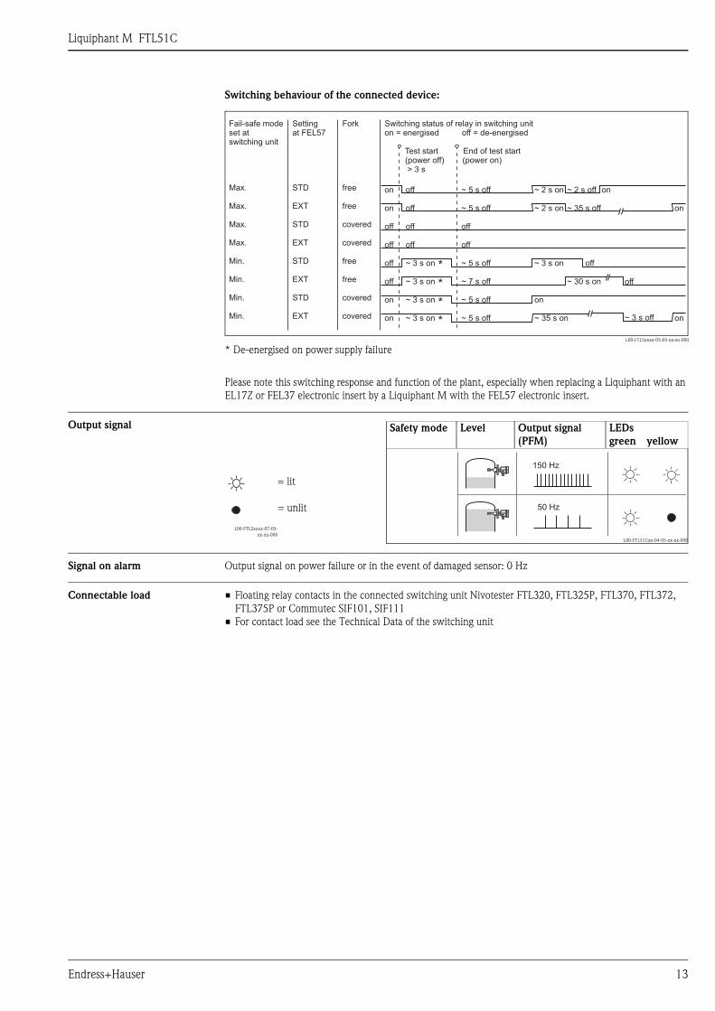
Switching behaviour of the connected device:
Please note this switching response and function of the plant, especially when replacing a Liquiphant with an EL17Z or FEL37 electronic insert by a Liquiphant M with the FEL57 electronic insert.
Output signal
Signal on alarm Output signal on power failure or in the event of damaged sensor: 0 Hz
Connectable load • Floating relay contacts in the connected switching unit Nivotester FTL320, FTL325P, FTL370, FTL372, FTL375P or Commutec SIF101, SIF111
• For contact load see the Technical Data of the switching unit
L00-FTL5xxxx-05-05-xx-en-000
* De-energised on power supply failure
Fail-safe modeset atswitching unit
Max.
Max.
Max.
Max.
Min.
Min.
Min.
Min.
Settingat FEL57
STD
EXT
STD
EXT
STD
EXT
STD
EXT
Fork
free
free
covered
covered
free
free
covered
covered
Switching status of relay in switching uniton = energised off = de-energised
Test start End of test start(power off) (power on)> 3 s
on
on
off
off
off
off
on
on
off
off
off
off
~ 3 s on
~ 3 s on
~ 3 s on
~ 3 s on
~ 5 s off
~ 5 s off
off
off
~ 5 s off
~ 7 s off
~ 5 s off
~ 5 s off
~ 2 s on
~ 2 s on
~ 3 s on
on
~ 35 s on ~ 3 s off
~ 2 s off
~ 35 s off
off
~ 30 s on
on
on
on
off
*
*
*
*
Safety mode Level Output signal(PFM)
LEDsgreen yellow
L00-FTL2xxxx-07-05-xx-xx-000
= lit
= unlit
L00-FTL51Cxx-04-05-xx-xx-008
150 Hz
50 Hz
Liquiphant M FTL51C
14 Endress+Hauser
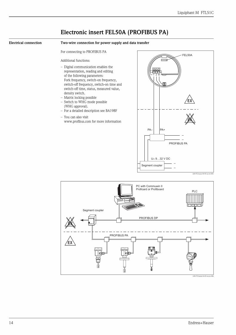
Electronic insert FEL50A (PROFIBUS PA)
Electrical connection Two-wire connection for power supply and data transfer
L00-FTL5xxxx-04-05-xx-en-006
For connecting to PROFIBUS PA
Additional functions:
– Digital communication enables the representation, reading and editing of the following parameters: Fork frequency, switch-on frequency, switch-off frequency, switch-on time and switch-off time, status, measured value, density switch.
– Matrix locking possible– Switch to WHG mode possible
(WHG approval).– For a detailed description see BA198F
– You can also visit www.profibus.com for more information
L00-FTL5xxxx-04-05-xx-en-005
PA– PA+
PROFIBUS PA
–
–
–
–
EX
EX
U– 9…32 V DC...
1 2
FEL50A
Segment coupler
PLC
PROFIBUS DP
PROFIBUS PA
EX
EX
PC with Commuwin IIProficard or Profiboard
Segment coupler
Liquiphant M FTL51C
Endress+Hauser 15
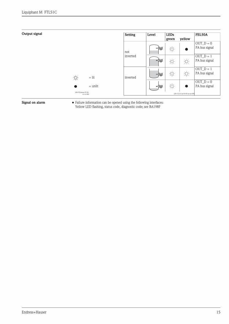
Output signal
Signal on alarm • Failure information can be opened using the following interfaces:Yellow LED flashing, status code, diagnostic code; see BA198F
Setting Level LEDsgreen yellow
FEL50A
L00-FTL2xxxx-07-05-xx-xx-000
notinverted
L00-FTL51Cxx-04-05-xx-xx-009
OUT_D = 0PA bus signal
OUT_D = 1PA bus signal
= lit inverted
OUT_D = 1PA bus signal
= unlitOUT_D = 0PA bus signal
Liquiphant M FTL51C
16 Endress+Hauser
Connection and function
Connecting cables • Electronic inserts: cross-section max. 2.5 mm2; strand in ferrule to DIN 46228• Protective earth in housing: cross-section max. 2.5 mm2
• External equipotential bonding connection on housing: cross-section max. 4 mm2
Safety mode Minimum/maximum residual current safety selectable on electronic insert(with FEL57 on Nivotester only)
Max. = maximum safety: The output switches to the power fail response when the fork is covered For use with overfill protection for example
Max. = minimum safety:The output switches to the power fail response when the fork is exposed For use with dry running protection for example
Switching time When fork is covered: approx. 0.5 sWhen fork is exposed: approx. 1.0 s(Other switching times on request.)
Additionally configurable for PROFIBUS PA: 0.5...60 s
Switch-on behaviour When switching on the power supply, the output assumes the alarm signal.After max. 3 s it assumes the correct switching mode (exception: FEL57)
Performance characteristics
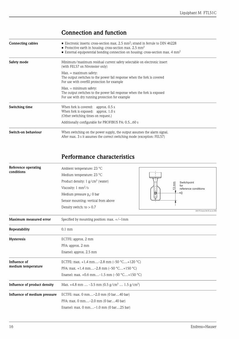
Reference operating conditions
Maximum measured error Specified by mounting position: max. +/–1mm
Repeatability 0.1 mm
Hysteresis ECTFE: approx. 2 mm
PFA: approx. 2 mm
Enamel: approx. 2.5 mm
Influence of medium temperature
ECTFE: max. +1.4 mm…–2.8 mm (–50 °C…+120 °C)
PFA: max. +1.4 mm…–2.8 mm (–50 °C…+150 °C)
Enamel: max. +0.6 mm…–1.5 mm (–50 °C…+150 °C)
Influence of product density Max. +4.8 mm … –3.5 mm (0.5 g/cm3 … 1.5 g/cm3)
Influence of medium pressure ECTFE: max. 0 mm…–2.0 mm (0 bar…40 bar)
PFA: max. 0 mm…–2.0 mm (0 bar…40 bar)
Enamel: max. 0 mm…–1.0 mm (0 bar…25 bar)
Ambient temperature: 23 °C
Medium temperature: 23 °C
Product density: 1 g/cm3 (water)
Viscosity: 1 mm2/s
Medium pressure pe: 0 bar
Sensor mounting: vertical from above
Density switch: to > 0.7L00-FTL5xxxx-06-05-xx-en-000
13
mm Switchpoint
forreference conditions
Liquiphant M FTL51C
Endress+Hauser 17
Operating conditions
Installation
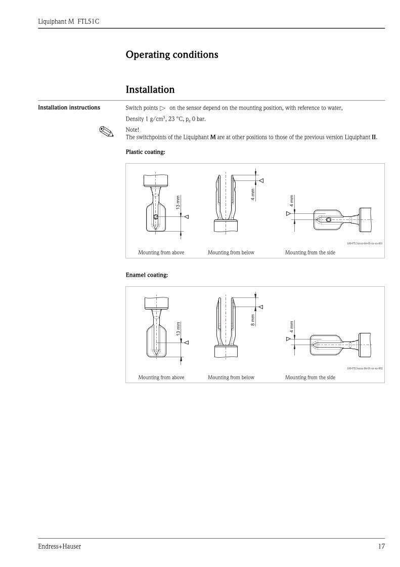
Installation instructions
! Note! The switchpoints of the Liquiphant M are at other positions to those of the previous version Liquiphant II.
Plastic coating:
Enamel coating:
Switch points on the sensor depend on the mounting position, with reference to water,
Density 1 g/cm3, 23 °C, pe 0 bar.
L00-FTL5xxxx-06-05-xx-xx-001
Mounting from above Mounting from below Mounting from the side
L00-FTL5xxxx-06-05-xx-xx-002
Mounting from above Mounting from below Mounting from the side
13
mm 4
mm
4m
m
13
mm 8
mm
4m
m
Liquiphant M FTL51C
18 Endress+Hauser
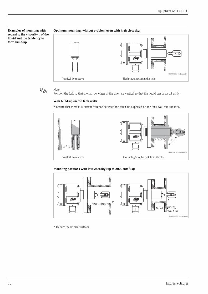
Examples of mounting with regard to the viscosity ν of the liquid and the tendency to form build-up
Optimum mounting, without problem even with high viscosity:
! Note! Position the fork so that the narrow edges of the tines are vertical so that the liquid can drain off easily.
With build-up on the tank walls:
Mounting positions with low viscosity (up to 2000 mm2/s):
L00-FTL51Cxx-11-05-xx-xx-002
Vertical from above Flush-mounted from the side
* Ensure that there is sufficient distance between the build-up expected on the tank wall and the fork.
L00-FTL51Cxx-11-05-xx-xx-003
Vertical from above Protruding into the tank from the side
L00-FTL51Cxx-11-05-xx-xx-004
* Deburr the nozzle surfaces
*
*
(min. 1 in)
min. 25DN 40
* *
Liquiphant M FTL51C
Endress+Hauser 19
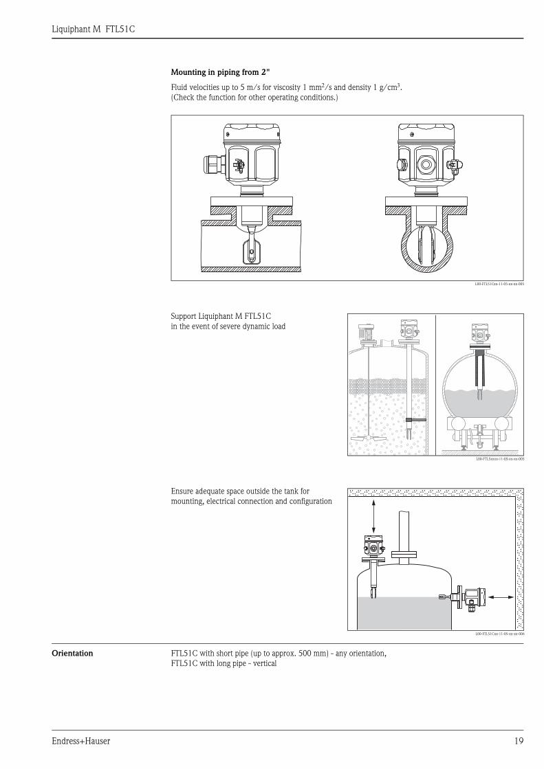
Mounting in piping from 2"
Orientation FTL51C with short pipe (up to approx. 500 mm) - any orientation,FTL51C with long pipe - vertical
Fluid velocities up to 5 m/s for viscosity 1 mm2/s and density 1 g/cm3.(Check the function for other operating conditions.)
L00-FTL51Cxx-11-05-xx-xx-005
Support Liquiphant M FTL51Cin the event of severe dynamic load
L00-FTL5xxxx-11-05-xx-xx-005
Ensure adequate space outside the tank formounting, electrical connection and configuration
L00-FTL51Cxx-11-05-xx-xx-006
.. .. .. .. .. .. .. .. .. .. .. .. .. .. .. .. .. .. .. .. .. .....
....
....
....
....
....
....
....
..
. .. .. .. .. .. .. .. .. .. .. .. .. .. .. .. .. .. .. .. .. .. ....
....
....
....
....
....
....
....
....
.. .. .. .. .. .. .. .. .. .. .. .. .. .. .. .. .. .. .. .. .. .. ....
....
....
....
....
....
....
....
....
.
. .. .. .. .. .. .. .. .. .. .. .. .. .. .. .. .. .. .. .. .. ......
....
....
....
....
....
....
....
...
Liquiphant M FTL51C
20 Endress+Hauser
Environment
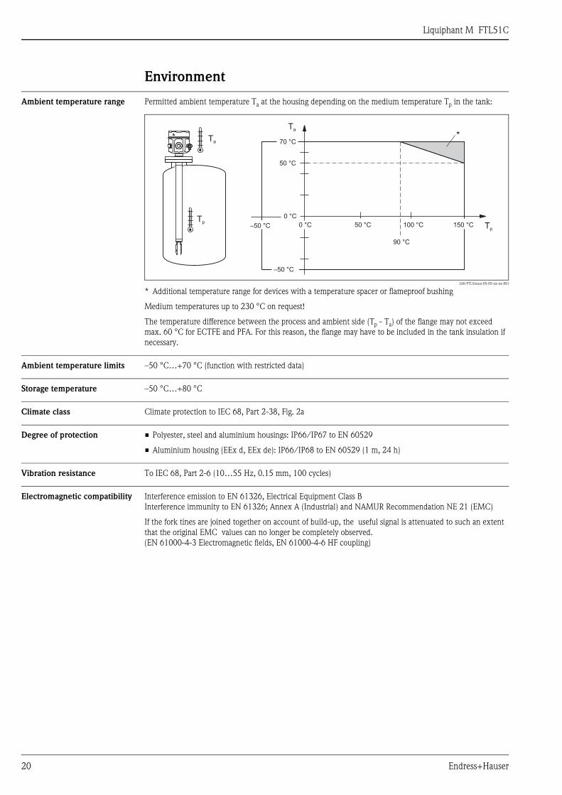
Ambient temperature range Permitted ambient temperature Ta at the housing depending on the medium temperature Tp in the tank:
Medium temperatures up to 230 °C on request!
The temperature difference between the process and ambient side (Tp - Ta) of the flange may not exceed max. 60 °C for ECTFE and PFA. For this reason, the flange may have to be included in the tank insulation if necessary.
Ambient temperature limits –50 °C…+70 °C (function with restricted data)
Storage temperature –50 °C…+80 °C
Climate class Climate protection to IEC 68, Part 2-38, Fig. 2a
Degree of protection • Polyester, steel and aluminium housings: IP66/IP67 to EN 60529
• Aluminium housing (EEx d, EEx de): IP66/IP68 to EN 60529 (1 m, 24 h)
Vibration resistance To IEC 68, Part 2-6 (10…55 Hz, 0.15 mm, 100 cycles)
Electromagnetic compatibility Interference emission to EN 61326, Electrical Equipment Class BInterference immunity to EN 61326; Annex A (Industrial) and NAMUR Recommendation NE 21 (EMC)
If the fork tines are joined together on account of build-up, the useful signal is attenuated to such an extent that the original EMC values can no longer be completely observed. (EN 61000-4-3 Electromagnetic fields, EN 61000-4-6 HF coupling)
L00-FTL5xxxx-05-05-xx-xx-001
* Additional temperature range for devices with a temperature spacer or flameproof bushing
Ta
Tp
70 °C
Ta
50 °C
0 °C
0 °C 50 °C
*
100 °C 150 °C Tp
90 °C
–50 °C
–50 °C
Liquiphant M FTL51C
Endress+Hauser 21
Medium conditions
Medium temperature range ECTFE: max. +1.4 mm…–2.8 mm (–50 °C…+120 °C)
PFA: max. +1.4 mm…–2.8 mm (–50 °C…+150 °C/to 230 °C on request)
Enamel: max. +0.6 mm…–1.5 mm (–50 °C…+150 °C/to 200 °C on request)
Thermal shock Max. 120 °C/s
Medium pressure pe ECTFE: –1 bar…+40 barPFA: –1 bar…+40 barEnamel: –1 bar…+25 barover the entire temperature range; for exceptions, see Process connections
Test pressure Max. 100 bar (1.5 times the medium pressure pe); no function during test pressureBurst pressure of diaphragm 200 bar
Pressure shock Max. 20 bar/s
State of aggregation Liquid
Density Min. 0.5 g/cm3
Other density settings on request
Viscosity Max. 10000 mm2/s
Solids content Max. ø5 mm
Liquiphant M FTL51C
22 Endress+Hauser
Mechanical construction
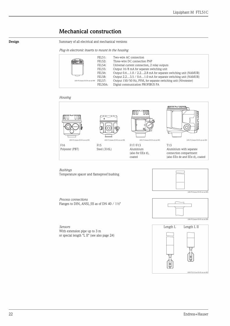
Design Summary of all electrical and mechanical versions
Plug-in electronic inserts to mount in the housing
Housing
L00-FTL5xxxx-03-05-xx-xx-000
FEL51: FEL52: FEL54: FEL55: FEL56:FEL58:FEL57:FEL50A:
Two-wire AC connectionThree-wire DC connection PNPUniversal current connection, 2 relay outputsOutput 16/8 mA for separate switching unitOutput 0.6…1.0 / 2.2…2.8 mA for separate switching unit (NAMUR)Output 2.2…3.5 / 0.6…1.0 mA for separate switching unit (NAMUR)Output 150/50 Hz, PFM, for separate switching unit (Nivotester)Digital communication PROFIBUS PA
L00-FTL5xxxx-03-05-xx-xx-001 L00-FTL5xxxx-03-05-xx-xx-002 L00-FTL5xxxx-03-05-xx-xx-003 L00-FTL5xxxx-03-05-xx-xx-004
F16Polyester (PBT)
F15Steel (316L)
F17/F13Aluminium(also for EEx d),coated
T13Aluminium with separate connection compartment (also EEx de and EEx d), coated
BushingsTemperature spacer and flameproof bushing
L00-FTL5xxxx-03-05-xx-xx-005
Process connectionsFlanges to DIN, ANSI, JIS as of DN 40 / 1½"
L00-FTL5xxxx-03-05-xx-xx-009
SensorsWith extension pipe up to 3 mor special length "L II" (see also page 24)
Length L Length L II
L00-FTL51Cxx-03-05-xx-xx-001
Liquiphant M FTL51C
Endress+Hauser 23
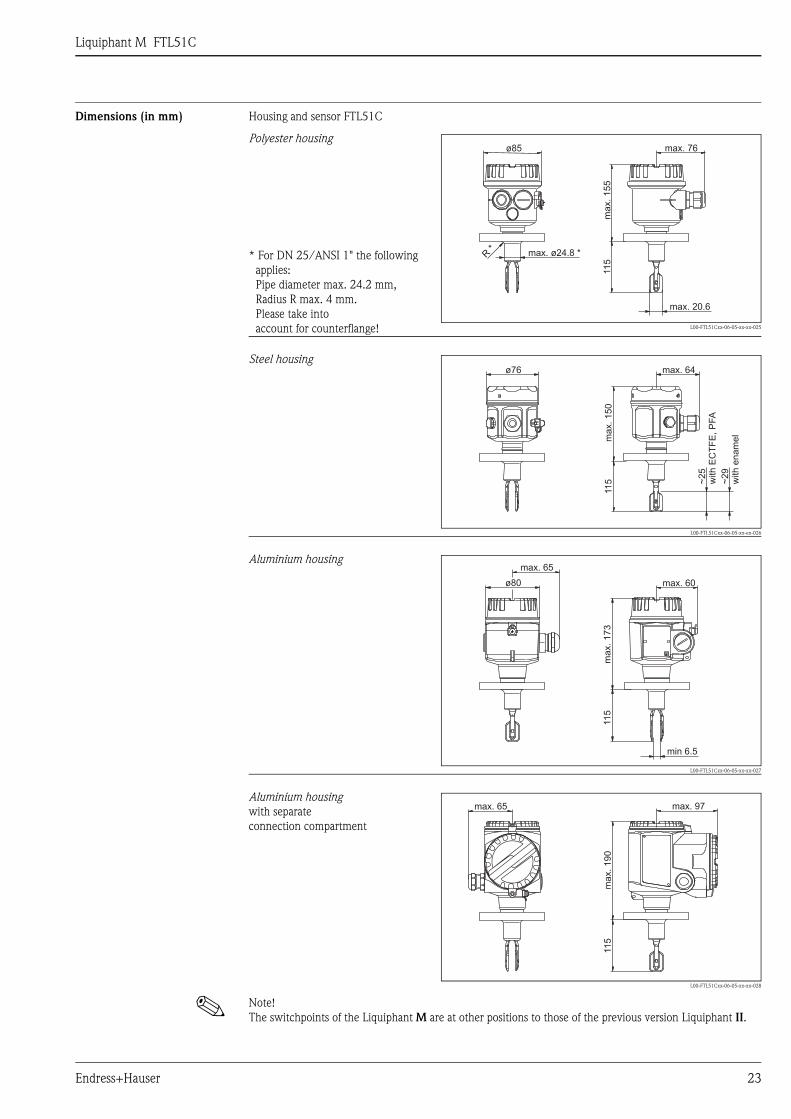
Dimensions (in mm) Housing and sensor FTL51C
! Note! The switchpoints of the Liquiphant M are at other positions to those of the previous version Liquiphant II.
Polyester housing
* For DN 25/ANSI 1" the followingapplies: Pipe diameter max. 24.2 mm,Radius R max. 4 mm.Please take into account for counterflange! L00-FTL51Cxx-06-05-xx-xx-025
Steel housing
L00-FTL51Cxx-06-05-xx-en-026
Aluminium housing
L00-FTL51Cxx-06-05-xx-xx-027
Aluminium housingwith separateconnection compartment
L00-FTL51Cxx-06-05-xx-xx-028
ø85 max. 76
max. ø24.8 *R*
max. 20.6
max.155
115
ø76 max. 64
ma
x.
15
011
5 ~2
5w
ith
EC
TF
E,
PFA
~2
9w
ith
en
am
el
ø80 max. 60
max. 65
ma
x.
17
311
5
min 6.5
max. 65 max. 97
ma
x.
19
011
5
Liquiphant M FTL51C
24 Endress+Hauser
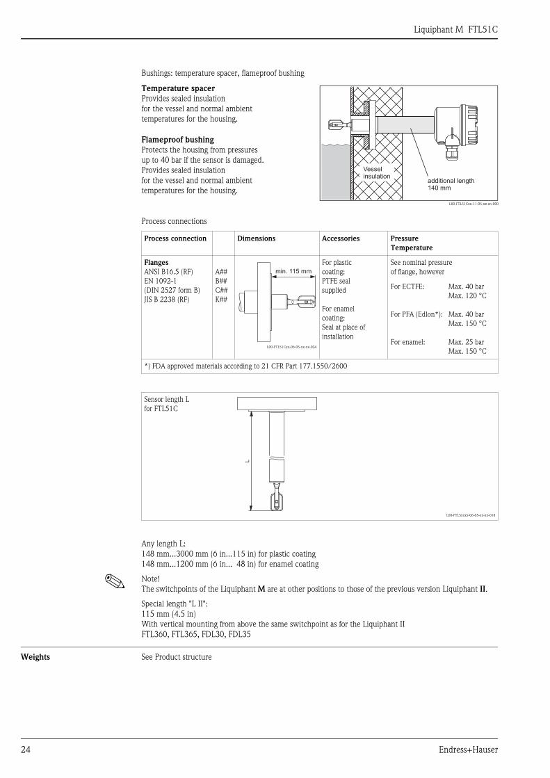
Bushings: temperature spacer, flameproof bushing
Process connections
Any length L:148 mm...3000 mm (6 in...115 in) for plastic coating148 mm...1200 mm (6 in... 48 in) for enamel coating
! Note! The switchpoints of the Liquiphant M are at other positions to those of the previous version Liquiphant II.
Special length "L II":115 mm (4.5 in)With vertical mounting from above the same switchpoint as for the Liquiphant IIFTL360, FTL365, FDL30, FDL35
Weights See Product structure
Temperature spacerProvides sealed insulationfor the vessel and normal ambienttemperatures for the housing.
L00-FTL51Cxx-11-05-xx-en-000
Flameproof bushingProtects the housing from pressures up to 40 bar if the sensor is damaged.Provides sealed insulationfor the vessel and normal ambienttemperatures for the housing.
Process connection Dimensions Accessories PressureTemperature
FlangesANSI B16.5 (RF)EN 1092-1(DIN 2527 form B)JIS B 2238 (RF)
A##B##C##K##
L00-FTL51Cxx-06-05-xx-xx-024
For plastic coating: PTFE sealsupplied
For enamelcoating: Seal at place of installation
See nominal pressure of flange, however
For ECTFE:
For PFA (Edlon*):
For enamel:
Max. 40 barMax. 120 °C
Max. 40 barMax. 150 °C
Max. 25 barMax. 150 °C
*) FDA approved materials according to 21 CFR Part 177.1550/2600
Sensor length L for FTL51C
L00-FTL5xxxx-06-05-xx-xx-018
additional length140 mm
Vesselinsulation
min. 115 mm
L

Liquiphant M FTL51C
Endress+Hauser 25
Material – Wetted parts:Process connection and extension pipe: AISI 316L (1.4435) or 2.4610 (Alloy C4)Tuning fork: AISI 316L (1.4435) or 2.4610 (Alloy C4)
– Polyester housing: PBT-FRwith PBT-FR cover or with PA12 cover with sight glass,Cover seal: EPDM
– Steel housing: AISI 316L Cover seal: silicone
– Aluminium housing: EN-AC-AlSi10Mg, plastic-coated,Cover seal: EPDM
– Compact housing: valve connector or M12 connector– Cable gland: polyamide or brass, nickel-plated– Temperature spacer: AISI 316L (1.4435)– Flameproof bushing: AISI 316L (1.4435)
Coating
Process connections Flanges to EN/DIN from DN 25, for standards see Product structure, to ANSI B16.5 from 1", to JIS B 2238 (RF) as of DN 50
Human interface
Electronic inserts
Layer thickness ECTFE PFA (EdlonTM)
PFA(RubyRed)
PFA(conductive)
Enamel
Lower limit 0.5 mm 0.45 mm 0.45 mm 0.45 mm 0.4 mm
Upper limit 1.6 mm 1.6 mm 1.6 mm 1.6 mm 0.8 mm
With FEL51, FEL52, FEL54, FEL55:2 switches for safety mode and density change,green LED to indicate operational status,red LED to indicate the switching status,flashes in the event of corrosion damage on sensoror if the electronics are defect
With FEL56:2 switches for safety mode and density change,green LED flashes to indicate the operational status,red LED to indicate the switching status,flashes in the event of corrosion damage on sensor or if the electronics are defect
With FEL57:2 switches for density change and cyclical checking,green LED to indicate operational status,yellow LED to indicate the covered status,flashes in the event of corrosion damage on sensor or if the electronics are defect
With FEL58:2 switches for safety mode and density change,green LED flashes quickly to indicate the operational statusflashes slowly in the event of corrosion damage on sensor or if the electronics are defect,yellow LED to indicate the switching status,Test key - breaks the cable connection
L00-FTL5xxxx-03-05-xx-en-001
L00-FTL5xxxx-03-05-xx-xx-013
Min
Max1
2
>0,7
>0,5
FEL51
1 2
L1 N U~19...253V AC50/60Hz
I max : 350mA
Connecting terminal LEDs Switches
Liquiphant M FTL51C
26 Endress+Hauser
Operating concept On-site configuration
Certificates and approvals
Certificates See Product structure
Combinations of coatings, housings and electronic inserts
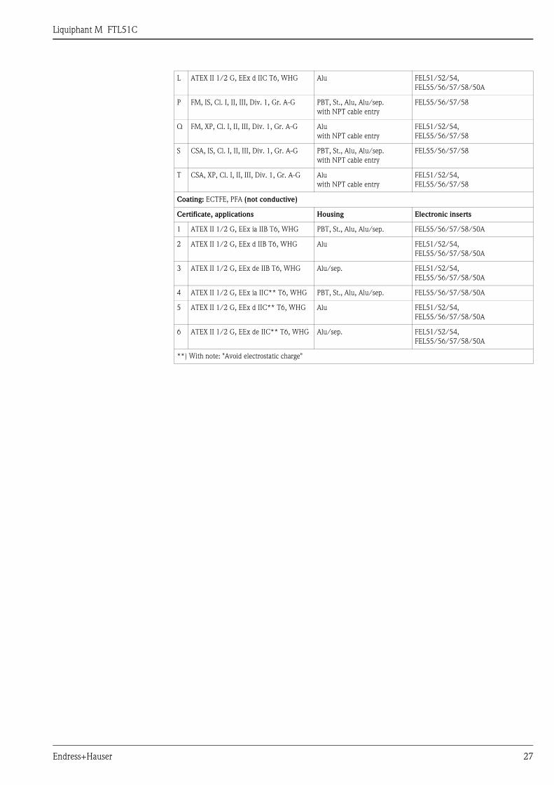
Based on the various certificates, permissible combinations of coatings, housings* and electronic inserts are given in the following table.*) Abbreviations: Polyester = PBT, Steel 1.4301/1.4435 (AISI 316L) = St., Aluminium = Alu
Aluminium housing with separate connection compartment = Alu/sep.
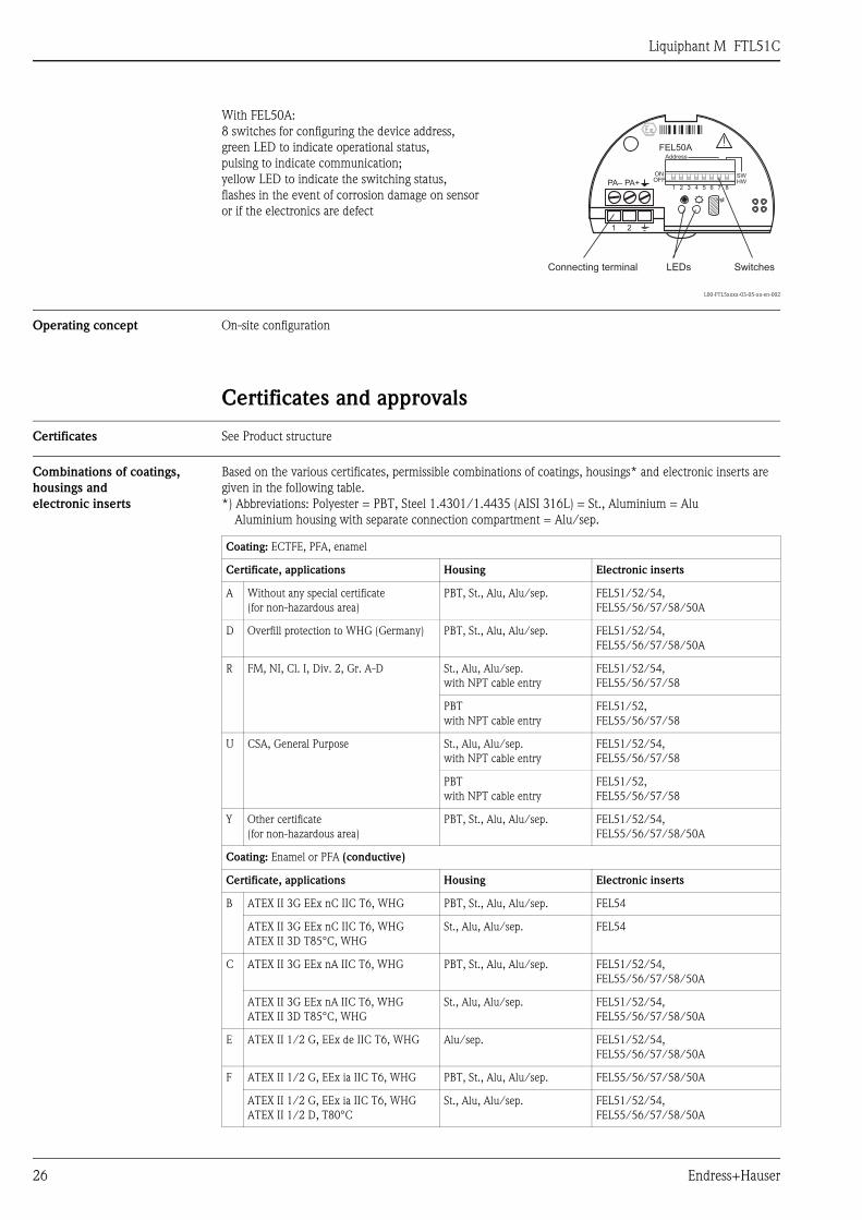
With FEL50A:8 switches for configuring the device address,green LED to indicate operational status,pulsing to indicate communication;yellow LED to indicate the switching status,flashes in the event of corrosion damage on sensor or if the electronics are defect
L00-FTL5xxxx-03-05-xx-en-002
HWOFFON
Address
SW
1 2 3 4 5 6 7 8
FEL50A
1 2
PA– PA+
Connecting terminal LEDs Switches
Coating: ECTFE, PFA, enamel
Certificate, applications Housing Electronic inserts
A Without any special certificate(for non-hazardous area)
PBT, St., Alu, Alu/sep. FEL51/52/54,FEL55/56/57/58/50A
D Overfill protection to WHG (Germany) PBT, St., Alu, Alu/sep. FEL51/52/54,FEL55/56/57/58/50A
R FM, NI, Cl. I, Div. 2, Gr. A-D St., Alu, Alu/sep.with NPT cable entry
FEL51/52/54,FEL55/56/57/58
PBTwith NPT cable entry
FEL51/52,FEL55/56/57/58
U CSA, General Purpose St., Alu, Alu/sep.with NPT cable entry
FEL51/52/54,FEL55/56/57/58
PBTwith NPT cable entry
FEL51/52, FEL55/56/57/58
Y Other certificate(for non-hazardous area)
PBT, St., Alu, Alu/sep. FEL51/52/54,FEL55/56/57/58/50A
Coating: Enamel or PFA (conductive)
Certificate, applications Housing Electronic inserts
B ATEX II 3G EEx nC IIC T6, WHG PBT, St., Alu, Alu/sep. FEL54
ATEX II 3G EEx nC IIC T6, WHGATEX II 3D T85°C, WHG
St., Alu, Alu/sep. FEL54
C ATEX II 3G EEx nA IIC T6, WHG PBT, St., Alu, Alu/sep. FEL51/52/54,FEL55/56/57/58/50A
ATEX II 3G EEx nA IIC T6, WHGATEX II 3D T85°C, WHG
St., Alu, Alu/sep. FEL51/52/54,FEL55/56/57/58/50A
E ATEX II 1/2 G, EEx de IIC T6, WHG Alu/sep. FEL51/52/54,FEL55/56/57/58/50A
F ATEX II 1/2 G, EEx ia IIC T6, WHG PBT, St., Alu, Alu/sep. FEL55/56/57/58/50A
ATEX II 1/2 G, EEx ia IIC T6, WHGATEX II 1/2 D, T80°C
St., Alu, Alu/sep. FEL51/52/54,FEL55/56/57/58/50A
Liquiphant M FTL51C
Endress+Hauser 27
L ATEX II 1/2 G, EEx d IIC T6, WHG Alu FEL51/52/54,FEL55/56/57/58/50A
P FM, IS, Cl. I, II, III, Div. 1, Gr. A-G PBT, St., Alu, Alu/sep.with NPT cable entry
FEL55/56/57/58
Q FM, XP, Cl. I, II, III, Div. 1, Gr. A-G Aluwith NPT cable entry
FEL51/52/54,FEL55/56/57/58
S CSA, IS, Cl. I, II, III, Div. 1, Gr. A-G PBT, St., Alu, Alu/sep.with NPT cable entry
FEL55/56/57/58
T CSA, XP, Cl. I, II, III, Div. 1, Gr. A-G Aluwith NPT cable entry
FEL51/52/54,FEL55/56/57/58
Coating: ECTFE, PFA (not conductive)
Certificate, applications Housing Electronic inserts
1 ATEX II 1/2 G, EEx ia IIB T6, WHG PBT, St., Alu, Alu/sep. FEL55/56/57/58/50A
2 ATEX II 1/2 G, EEx d IIB T6, WHG Alu FEL51/52/54,FEL55/56/57/58/50A
3 ATEX II 1/2 G, EEx de IIB T6, WHG Alu/sep. FEL51/52/54,FEL55/56/57/58/50A
4 ATEX II 1/2 G, EEx ia IIC** T6, WHG PBT, St., Alu, Alu/sep. FEL55/56/57/58/50A
5 ATEX II 1/2 G, EEx d IIC** T6, WHG Alu FEL51/52/54,FEL55/56/57/58/50A
6 ATEX II 1/2 G, EEx de IIC** T6, WHG Alu/sep. FEL51/52/54,FEL55/56/57/58/50A
**) With note: "Avoid electrostatic charge"
Liquiphant M FTL51C
28 Endress+Hauser
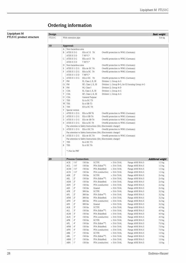
Ordering information
Liquiphant MFTL51C product structure
Design Basic weightBasic weightBasic weightBasic weightFTL51C With extension pipe 0.6 kg
10 Approval:A Non-hazardous areaB ATEX II 3 G EEx nC II T6 Overfill protection to WHG (Germany)
ATEX II 3 D T 85°C*C ATEX II 3 G EEx nA II T6 Overfill protection to WHG (Germany)
ATEX II 3 D T 85°C*D Non-hazardous area Overfill protection to WHG (Germany)E ATEX II 1/2 G EEx de IIC T6 Overfill protection to WHG (Germany)F ATEX II 1/2 G EEx ia IIC T6 Overfill protection to WHG (Germany)
ATEX II 1/2 D T 80°C*L ATEX II 1/2 G EEx d IIC T6 Overfill protection to WHG (Germany)P FM IS, Class I, II, III Division 1, Group A-GQ FM XP, Class I, II, III Division 1, Group B-G, for E5 housing Group A-GR FM NI, Class I Division 2, Group A-DS CSA IS, Class I, II, III Division 1, Group A-GT CSA XP, Class I, II, III Division 1, Group A-GU CSA General PurposeV TIIS Ex ia IIC T3W TIIS Ex d IIB T3X TIIS EX ia IIC T6Y Special version1 ATEX II 1/2 G EEx ia IIB T6 Overfill protection to WHG (Germany)2 ATEX II 1/2 G EEx d IIB T6 Overfill protection to WHG (Germany)3 ATEX II 1/2 G EEx de IIB T6 Overfill protection to WHG (Germany)4 ATEX II 1/2 G EEx ia IIC T6 Overfill protection to WHG (Germany)
Pay attention to Safety Instructions (XA) (Electrostatic charge)!5 ATEX II 1/2 G EEx d IIC T6 Overfill protection to WHG (Germany)
Pay attention to Safety Instructions (XA) (Electrostatic charge)!6 ATEX II 1/2 G EEx de IIC T6 Overfill protection to WHG (Germany)
Pay attention to Safety Instructions (XA) (Electrostatic charge)!7 TIIS Ex d IIC T38 TIIS Ex d IIC T6
*) Not for PBT
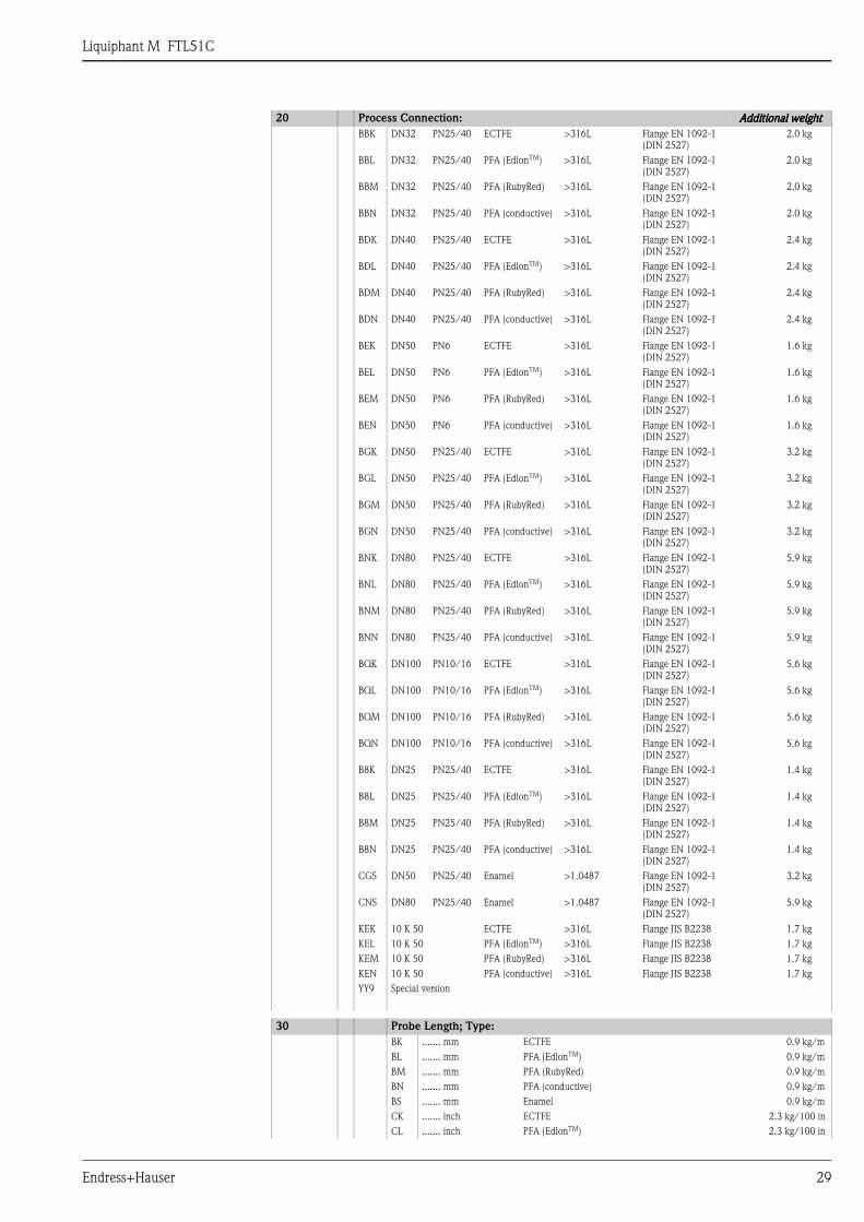
20 Process Connection: Additional weightAdditional weightAdditional weightAdditional weightACK 1½" 150 lbs ECTFE > 316/316L Flange ANSI B16.5 1.5 kgACL 1½" 150 lbs PFA (EdlonTM) > 316/316L Flange ANSI B16.5 1.5 kgACM 1½" 150 lbs PFA (RubyRed) > 316/316L Flange ANSI B16.5 1.5 kgACN 1½" 150 lbs PFA (conductive) > 316/316L Flange ANSI B16.5 1.5 kgAEK 2" 150 lbs ECTFE > 316/316L Flange ANSI B16.5 2.4 kgAEL 2" 150 lbs PFA (EdlonTM) > 316/316L Flange ANSI B16.5 2.4 kgAEM 2" 150 lbs PFA (RubyRed) > 316/316L Flange ANSI B16.5 2.4 kgAEN 2" 150 lbs PFA (conductive) > 316/316L Flange ANSI B16.5 2.4 kgAES 2" 150 lbs Enamel > 316/316L Flange ANSI B16.5 2.4 kgAFK 2" 300 lbs ECTFE > 316/316L Flange ANSI B16.5 3.2 kgAFL 2" 300 lbs PFA (EdlonTM) > 316/316L Flange ANSI B16.5 3.2 kgAFM 2" 300 lbs PFA (RubyRed) > 316/316L Flange ANSI B16.5 3.2 kgAFN 2" 300 lbs PFA (conductive) > 316/316L Flange ANSI B16.5 3.2 kgAFS 2" 300 lbs Enamel > 316/316L Flange ANSI B16.5 3.2 kgALK 3" 150 lbs ECTFE > 316/316L Flange ANSI B16.5 4.9 kgALL 3" 150 lbs PFA (EdlonTM) > 316/316L Flange ANSI B16.5 4.9 kgALM 3" 150 lbs PFA (RubyRed) > 316/316L Flange ANSI B16.5 4.9 kgALN 3" 150 lbs PFA (conductive) > 316/316L Flange ANSI B16.5 4.9 kgAPK 4" 150 lbs ECTFE > 316/316L Flange ANSI B16.5 7.0 kgAPL 4" 150 lbs PFA (EdlonTM) > 316/316L Flange ANSI B16.5 7.0 kgAPM 4" 150 lbs PFA (RubyRed) > 316/316L Flange ANSI B16.5 7.0 kgAPN 4" 150 lbs PFA (conductive) > 316/316L Flange ANSI B16.5 7.0 kgA8K 1" 150 lbs ECTFE > 316/316L Flange ANSI B16.5 1.0 kgA8L 1" 150 lbs PFA (EdlonTM) > 316/316L Flange ANSI B16.5 1.0 kgA8M 1" 150 lbs PFA (RubyRed) > 316/316L Flange ANSI B16.5 1.0 kgA8N 1" 150 lbs PFA (conductive) > 316/316L Flange ANSI B16.5 1.0 kg
Liquiphant M FTL51C
Endress+Hauser 29
BBK DN32 PN25/40 ECTFE >316L Flange EN 1092-1(DIN 2527)
2.0 kg
BBL DN32 PN25/40 PFA (EdlonTM) >316L Flange EN 1092-1(DIN 2527)
2.0 kg
BBM DN32 PN25/40 PFA (RubyRed) >316L Flange EN 1092-1(DIN 2527)
2.0 kg
BBN DN32 PN25/40 PFA (conductive) >316L Flange EN 1092-1(DIN 2527)
2.0 kg
BDK DN40 PN25/40 ECTFE >316L Flange EN 1092-1(DIN 2527)
2.4 kg
BDL DN40 PN25/40 PFA (EdlonTM) >316L Flange EN 1092-1(DIN 2527)
2.4 kg
BDM DN40 PN25/40 PFA (RubyRed) >316L Flange EN 1092-1(DIN 2527)
2.4 kg
BDN DN40 PN25/40 PFA (conductive) >316L Flange EN 1092-1(DIN 2527)
2.4 kg
BEK DN50 PN6 ECTFE >316L Flange EN 1092-1(DIN 2527)
1.6 kg
BEL DN50 PN6 PFA (EdlonTM) >316L Flange EN 1092-1(DIN 2527)
1.6 kg
BEM DN50 PN6 PFA (RubyRed) >316L Flange EN 1092-1(DIN 2527)
1.6 kg
BEN DN50 PN6 PFA (conductive) >316L Flange EN 1092-1(DIN 2527)
1.6 kg
BGK DN50 PN25/40 ECTFE >316L Flange EN 1092-1(DIN 2527)
3.2 kg
BGL DN50 PN25/40 PFA (EdlonTM) >316L Flange EN 1092-1(DIN 2527)
3.2 kg
BGM DN50 PN25/40 PFA (RubyRed) >316L Flange EN 1092-1(DIN 2527)
3.2 kg
BGN DN50 PN25/40 PFA (conductive) >316L Flange EN 1092-1(DIN 2527)
3.2 kg
BNK DN80 PN25/40 ECTFE >316L Flange EN 1092-1(DIN 2527)
5.9 kg
BNL DN80 PN25/40 PFA (EdlonTM) >316L Flange EN 1092-1(DIN 2527)
5.9 kg
BNM DN80 PN25/40 PFA (RubyRed) >316L Flange EN 1092-1(DIN 2527)
5.9 kg
BNN DN80 PN25/40 PFA (conductive) >316L Flange EN 1092-1(DIN 2527)
5.9 kg
BQK DN100 PN10/16 ECTFE >316L Flange EN 1092-1(DIN 2527)
5.6 kg
BQL DN100 PN10/16 PFA (EdlonTM) >316L Flange EN 1092-1(DIN 2527)
5.6 kg
BQM DN100 PN10/16 PFA (RubyRed) >316L Flange EN 1092-1(DIN 2527)
5.6 kg
BQN DN100 PN10/16 PFA (conductive) >316L Flange EN 1092-1(DIN 2527)
5.6 kg
B8K DN25 PN25/40 ECTFE >316L Flange EN 1092-1(DIN 2527)
1.4 kg
B8L DN25 PN25/40 PFA (EdlonTM) >316L Flange EN 1092-1(DIN 2527)
1.4 kg
B8M DN25 PN25/40 PFA (RubyRed) >316L Flange EN 1092-1(DIN 2527)
1.4 kg
B8N DN25 PN25/40 PFA (conductive) >316L Flange EN 1092-1(DIN 2527)
1.4 kg
CGS DN50 PN25/40 Enamel >1.0487 Flange EN 1092-1(DIN 2527)
3.2 kg
CNS DN80 PN25/40 Enamel >1.0487 Flange EN 1092-1(DIN 2527)
5.9 kg
KEK 10 K 50 ECTFE >316L Flange JIS B2238 1.7 kgKEL 10 K 50 PFA (EdlonTM) >316L Flange JIS B2238 1.7 kgKEM 10 K 50 PFA (RubyRed) >316L Flange JIS B2238 1.7 kgKEN 10 K 50 PFA (conductive) >316L Flange JIS B2238 1.7 kgYY9 Special version
30 Probe Length; Type:BK ....... mm ECTFE 0.9 kg/mBL ....... mm PFA (EdlonTM) 0.9 kg/mBM ....... mm PFA (RubyRed) 0.9 kg/mBN ....... mm PFA (conductive) 0.9 kg/mBS ....... mm Enamel 0.9 kg/mCK ....... inch ECTFE 2.3 kg/100 inCL ....... inch PFA (EdlonTM) 2.3 kg/100 in
20 Process Connection: Additional weightAdditional weightAdditional weightAdditional weight
Liquiphant M FTL51C
30 Endress+Hauser
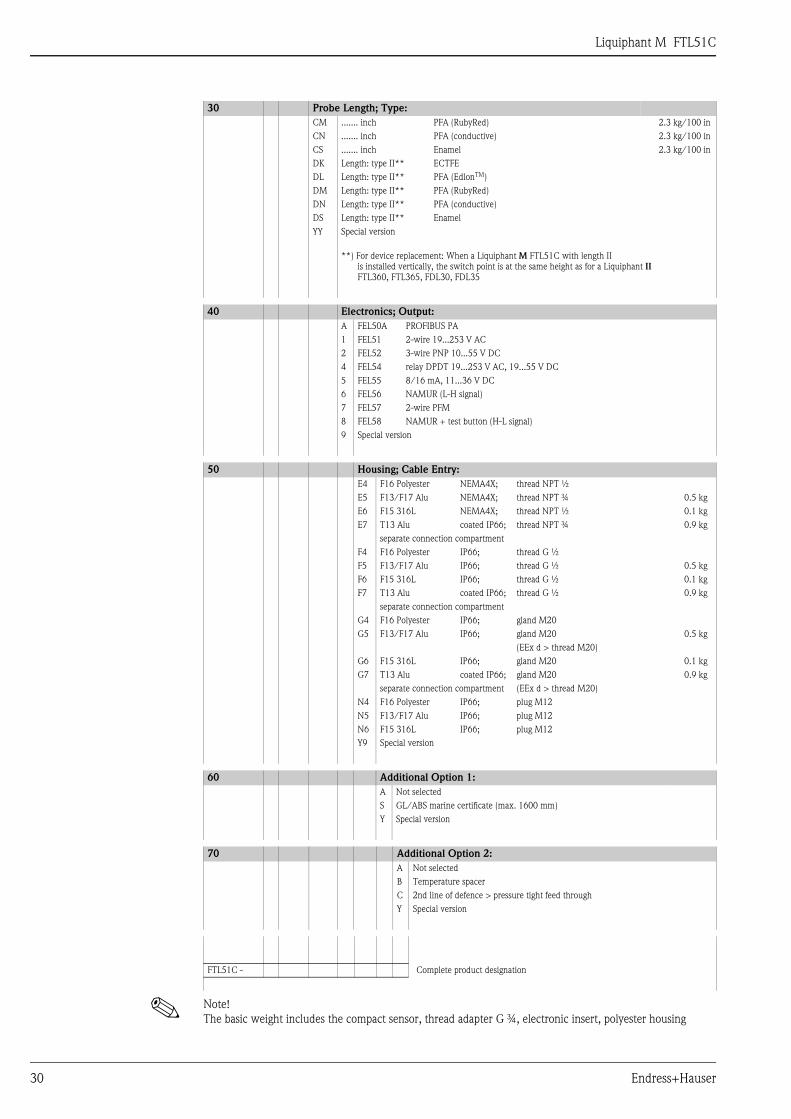
! Note! The basic weight includes the compact sensor, thread adapter G ¾, electronic insert, polyester housing
CM ....... inch PFA (RubyRed) 2.3 kg/100 inCN ....... inch PFA (conductive) 2.3 kg/100 inCS ....... inch Enamel 2.3 kg/100 inDK Length: type II** ECTFEDL Length: type II** PFA (EdlonTM)DM Length: type II** PFA (RubyRed)DN Length: type II** PFA (conductive)DS Length: type II** EnamelYY Special version
**) For device replacement: When a Liquiphant M FTL51C with length II is installed vertically, the switch point is at the same height as for a Liquiphant II FTL360, FTL365, FDL30, FDL35
40 Electronics; Output:A FEL50A PROFIBUS PA1 FEL51 2-wire 19...253 V AC2 FEL52 3-wire PNP 10...55 V DC4 FEL54 relay DPDT 19...253 V AC, 19...55 V DC5 FEL55 8/16 mA, 11...36 V DC6 FEL56 NAMUR (L-H signal)7 FEL57 2-wire PFM8 FEL58 NAMUR + test button (H-L signal)9 Special version
50 Housing; Cable Entry:E4 F16 Polyester NEMA4X; thread NPT ½E5 F13/F17 Alu NEMA4X; thread NPT ¾ 0.5 kgE6 F15 316L NEMA4X; thread NPT ½ 0.1 kgE7 T13 Alu coated IP66; thread NPT ¾ 0.9 kg
separate connection compartmentF4 F16 Polyester IP66; thread G ½F5 F13/F17 Alu IP66; thread G ½ 0.5 kgF6 F15 316L IP66; thread G ½ 0.1 kgF7 T13 Alu coated IP66; thread G ½ 0.9 kg
separate connection compartmentG4 F16 Polyester IP66; gland M20G5 F13/F17 Alu IP66; gland M20 0.5 kg
(EEx d > thread M20)G6 F15 316L IP66; gland M20 0.1 kgG7 T13 Alu coated IP66; gland M20 0.9 kg
separate connection compartment (EEx d > thread M20)N4 F16 Polyester IP66; plug M12N5 F13/F17 Alu IP66; plug M12N6 F15 316L IP66; plug M12Y9 Special version
60 Additional Option 1:A Not selectedS GL/ABS marine certificate (max. 1600 mm)Y Special version
70 Additional Option 2:A Not selectedB Temperature spacerC 2nd line of defence > pressure tight feed throughY Special version
FTL51C - Complete product designation
30 Probe Length; Type:
Liquiphant M FTL51C
Endress+Hauser 31
Accessories
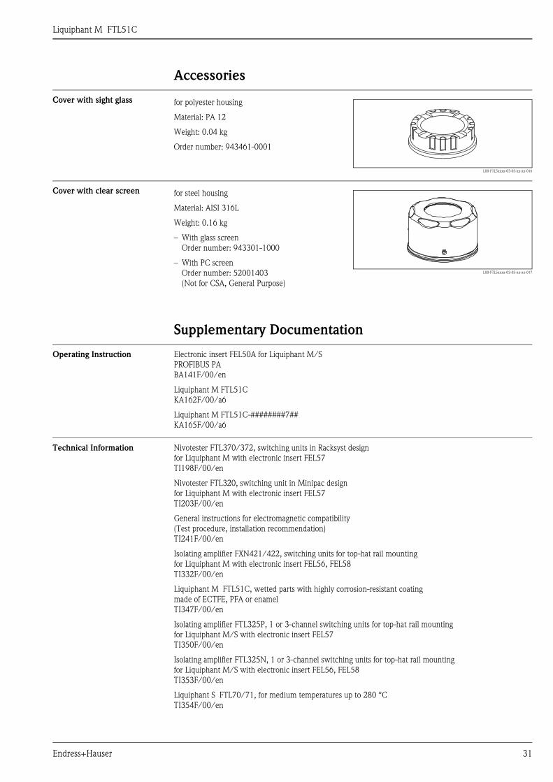
Cover with sight glass
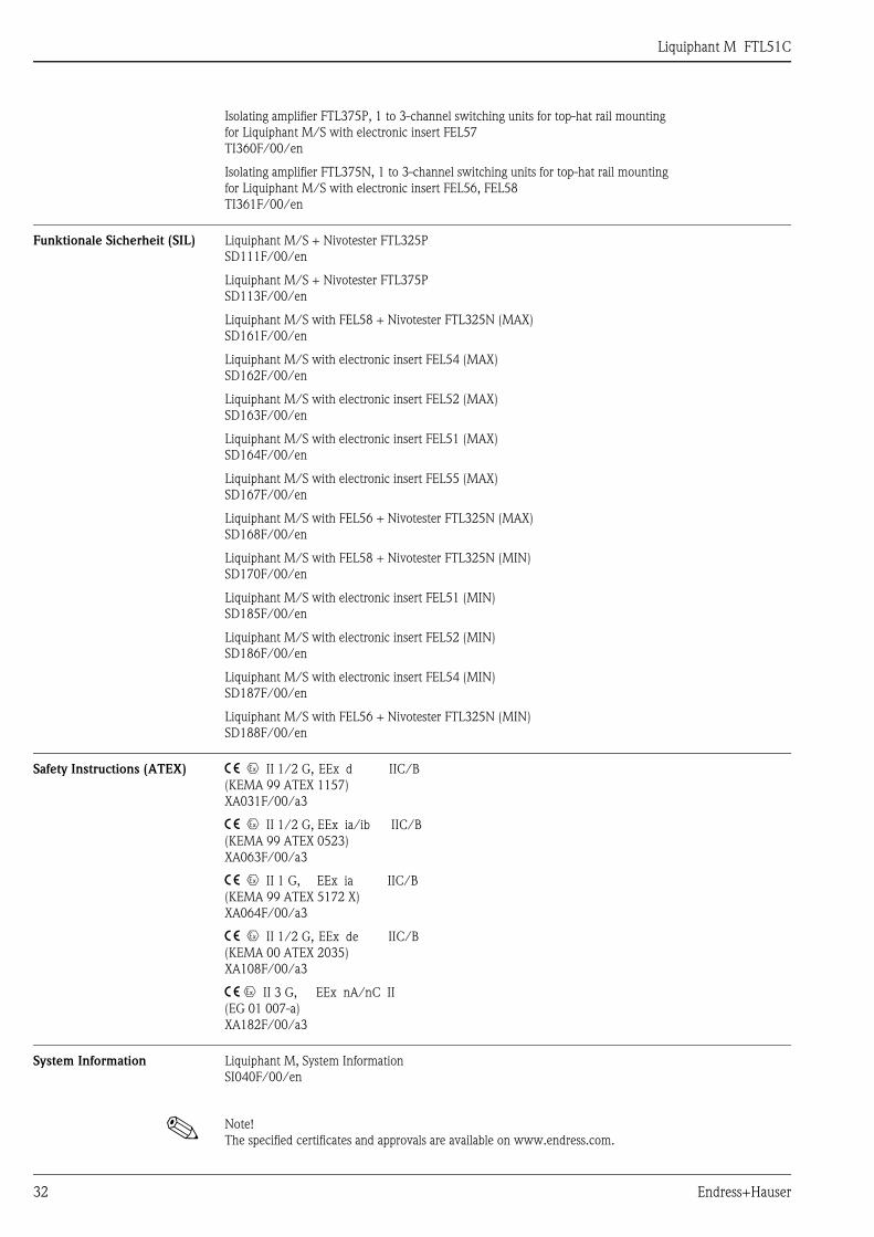
Cover with clear screen
Supplementary Documentation
Operating Instruction Electronic insert FEL50A for Liquiphant M/SPROFIBUS PABA141F/00/en
Liquiphant M FTL51CKA162F/00/a6
Liquiphant M FTL51C-########7##KA165F/00/a6
Technical Information Nivotester FTL370/372, switching units in Racksyst design for Liquiphant M with electronic insert FEL57TI198F/00/en
Nivotester FTL320, switching unit in Minipac design for Liquiphant M with electronic insert FEL57TI203F/00/en
General instructions for electromagnetic compatibility(Test procedure, installation recommendation)TI241F/00/en
Isolating amplifier FXN421/422, switching units for top-hat rail mounting for Liquiphant M with electronic insert FEL56, FEL58TI332F/00/en
Liquiphant M FTL51C, wetted parts with highly corrosion-resistant coatingmade of ECTFE, PFA or enamelTI347F/00/en
Isolating amplifier FTL325P, 1 or 3-channel switching units for top-hat rail mountingfor Liquiphant M/S with electronic insert FEL57TI350F/00/en
Isolating amplifier FTL325N, 1 or 3-channel switching units for top-hat rail mounting for Liquiphant M/S with electronic insert FEL56, FEL58TI353F/00/en
Liquiphant S FTL70/71, for medium temperatures up to 280 °CTI354F/00/en
for polyester housing
Material: PA 12
Weight: 0.04 kg
Order number: 943461-0001
L00-FTL5xxxx-03-05-xx-xx-016
for steel housing
Material: AISI 316L
Weight: 0.16 kg
– With glass screenOrder number: 943301-1000
– With PC screenOrder number: 52001403 (Not for CSA, General Purpose)
L00-FTL5xxxx-03-05-xx-xx-017
Liquiphant M FTL51C
32 Endress+Hauser
Isolating amplifier FTL375P, 1 to 3-channel switching units for top-hat rail mounting for Liquiphant M/S with electronic insert FEL57TI360F/00/en
Isolating amplifier FTL375N, 1 to 3-channel switching units for top-hat rail mountingfor Liquiphant M/S with electronic insert FEL56, FEL58TI361F/00/en
Funktionale Sicherheit (SIL) Liquiphant M/S + Nivotester FTL325PSD111F/00/en
Liquiphant M/S + Nivotester FTL375P SD113F/00/en
Liquiphant M/S with FEL58 + Nivotester FTL325N (MAX)SD161F/00/en
Liquiphant M/S with electronic insert FEL54 (MAX)SD162F/00/en
Liquiphant M/S with electronic insert FEL52 (MAX)SD163F/00/en
Liquiphant M/S with electronic insert FEL51 (MAX)SD164F/00/en
Liquiphant M/S with electronic insert FEL55 (MAX)SD167F/00/en
Liquiphant M/S with FEL56 + Nivotester FTL325N (MAX)SD168F/00/en
Liquiphant M/S with FEL58 + Nivotester FTL325N (MIN)SD170F/00/en
Liquiphant M/S with electronic insert FEL51 (MIN)SD185F/00/en
Liquiphant M/S with electronic insert FEL52 (MIN)SD186F/00/en
Liquiphant M/S with electronic insert FEL54 (MIN)SD187F/00/en
Liquiphant M/S with FEL56 + Nivotester FTL325N (MIN)SD188F/00/en
Safety Instructions (ATEX) 4 0 II 1/2 G, EEx d IIC/B(KEMA 99 ATEX 1157)XA031F/00/a3
4 0 II 1/2 G, EEx ia/ib IIC/B(KEMA 99 ATEX 0523)XA063F/00/a3
4 0 II 1 G, EEx ia IIC/B(KEMA 99 ATEX 5172 X)XA064F/00/a3
4 0 II 1/2 G, EEx de IIC/B(KEMA 00 ATEX 2035)XA108F/00/a3
4 0 II 3 G, EEx nA/nC II(EG 01 007-a)XA182F/00/a3
System Information Liquiphant M, System InformationSI040F/00/en
! Note! The specified certificates and approvals are available on www.endress.com.

Liquiphant M FTL51C
Endress+Hauser 33

Liquiphant M FTL51C
34 Endress+Hauser

Liquiphant M FTL51C
Endress+Hauser 35
Liquiphant M FTL51C
International Head Quarter
Endress+Hauser
GmbH+Co. KG
Instruments International
Colmarer Str. 6
79576 Weil am Rhein
Deutschland
Tel. +49 76 21 9 75 02
Fax +49 76 21 9 75 34 5
www.endress.com
TI347F/00/en/03.06SL/FM+SGML6.0 ProMoDo