Embed Size (px)
Citation preview
7/27/2019 Layout Arrangement for Centrifugal Pump Piping
http://slidepdf.com/reader/full/layout-arrangement-for-centrifugal-pump-piping 1/20
Layout Arrangement for Centrifugal Pump Piping
By A JAD
Layout arrangement for Centri fugal Pump Piping
1. GENERAL
The design of a piping system can have an important effect on the successful operation of acentrifugal
pump. Such items as pump design, suction piping design, suction and discharge pipe size and pipe
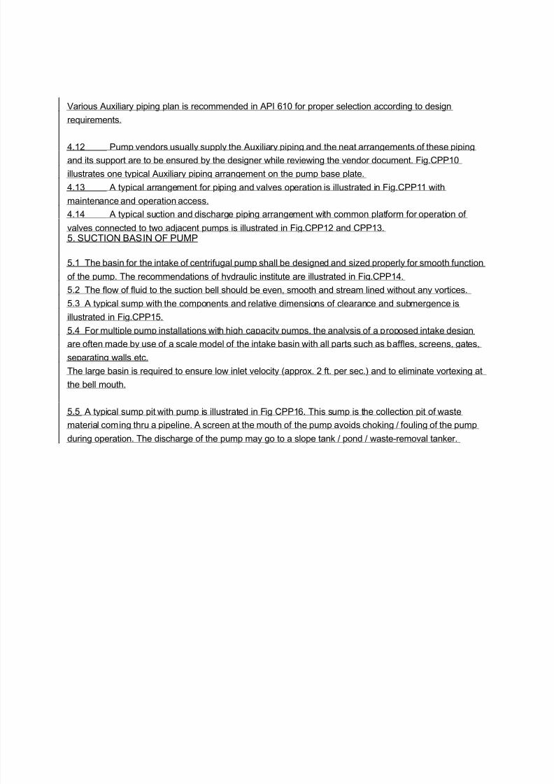
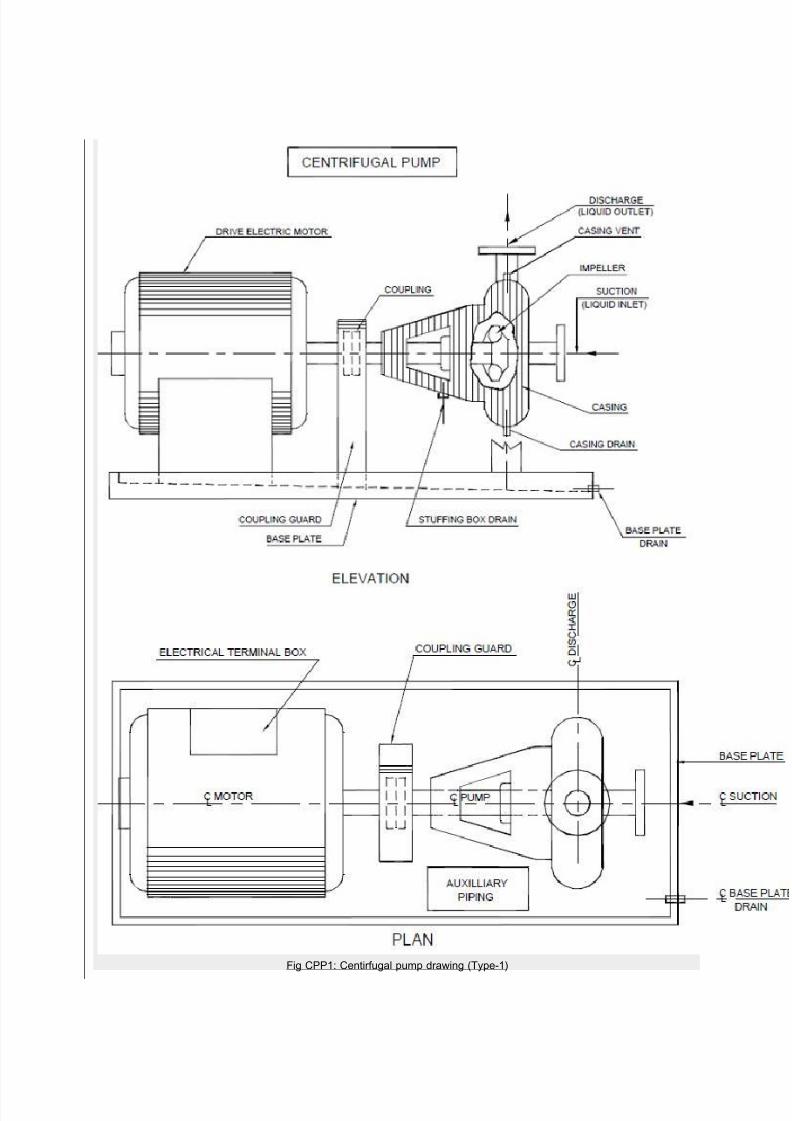
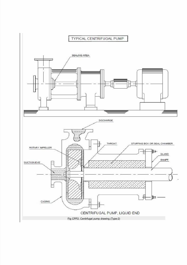
supports must all be carefully considered. A typical horizontal centrifugal pump installation is illustrated
in Fig.CPP1, CPP2, CPP3.
Selection of the discharge pipe size is primarily a matter of economics. The cost of various pipe sizes
must be compared to the pump size and power cost required to overcome the resulting friction head.
1.1 The suction piping size and design is far more important. Many centrifugal pump troubles are
caused by poor suction conditions.
1.2 The suction pipe should never be smaller than the suction nozzle of the pump and in most cases it
should be at least one size larger. Suction pipes should be as short and as straight as possible.
Suction pipe velocities should be in the 1.0 – 1.5 metre per second range, unless suction conditions are
unusually good. Higher velocities will increase the friction loss and can result in trouble some air and
vapour separation. This is further complicated when elbows or tees are located adjacent to the pump
suction nozzle. In that case uneven flow patterns or vapour separation keeps the liquid from evenly filling
the impeller. This upsets hydraulic balance leading to noise, vibration, possible
cavitation and excessive shaft deflection. Cavitation, erosion damage, shaft breakage or
permature bearing failure etc. may result.
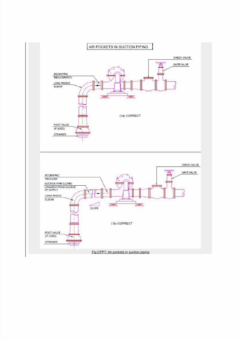
1.3 On pump installations involving suction lift, air pockets in the suction line can be a source of trouble.
The suction pipe should be exactly horizontal or with a uniform slope upward from the sump to the pump
as illustrated in Fig.CPP7. There should be no high spots where air can collect and cause the pump to
lose its prime. Eccentric rather than concentric reducers with flat side top should always be used.
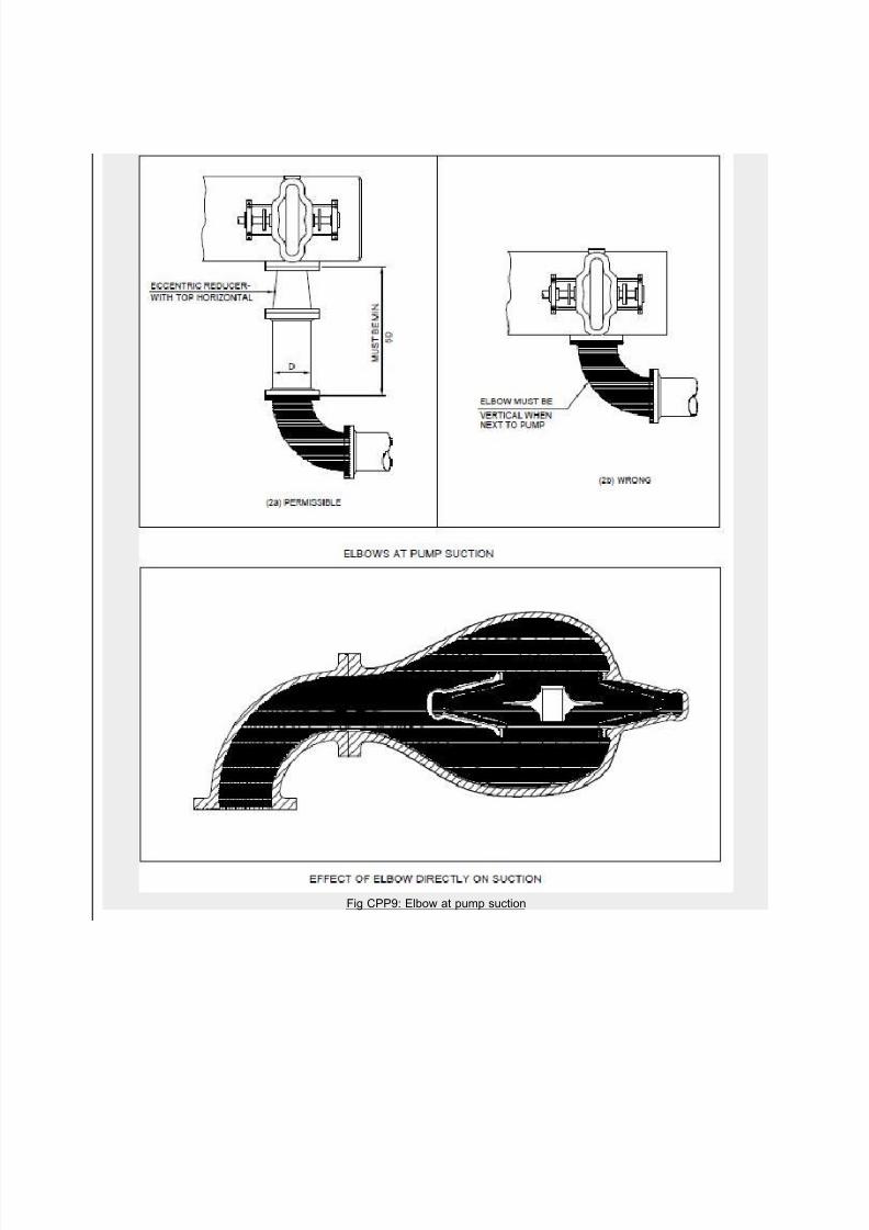
1.4 If an elbow is required at the suction of a double suction pump, it should be in a vertical position if at
all possible. Where it is necessary for some reason to use a horizontal elbow, it should be a long radiuselbow and there should be a minimum of five diameters of straight pipe between elbow and the pump
suction as illustrated in Fig.CPP9.2. LOCATION
2.1 Common location of pumps in chemical and petrochemical plant is under the piperack at grade.
Pumps are to be placed close to and below the vessels from which they take their suction in order to have
net-positive suction head (NPSH) required by the pump.
7/27/2019 Layout Arrangement for Centrifugal Pump Piping
http://slidepdf.com/reader/full/layout-arrangement-for-centrifugal-pump-piping 2/20
2.2 Any reduction in suction line size required at pumps should be made with eccentric reducers, with flat
side up to avoid accumulation of vapour pocket. Changes in direction of suction lines should be at least
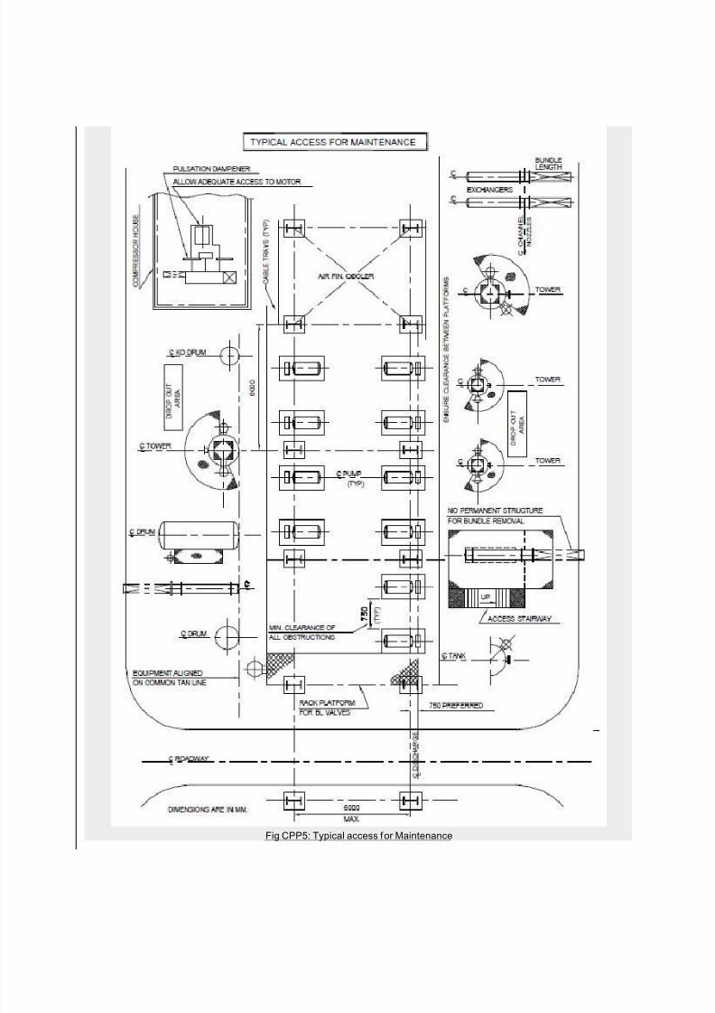
600mm away from the pump suction.2.3 Pumps should be arranged in line with drivers facing the access gangway. Clearances and piping
should provide free access to one side of the driver and pump. There must be good access to gland / seal
and coupling where most of the maintenance and adjustments are done.
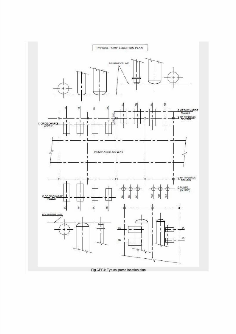
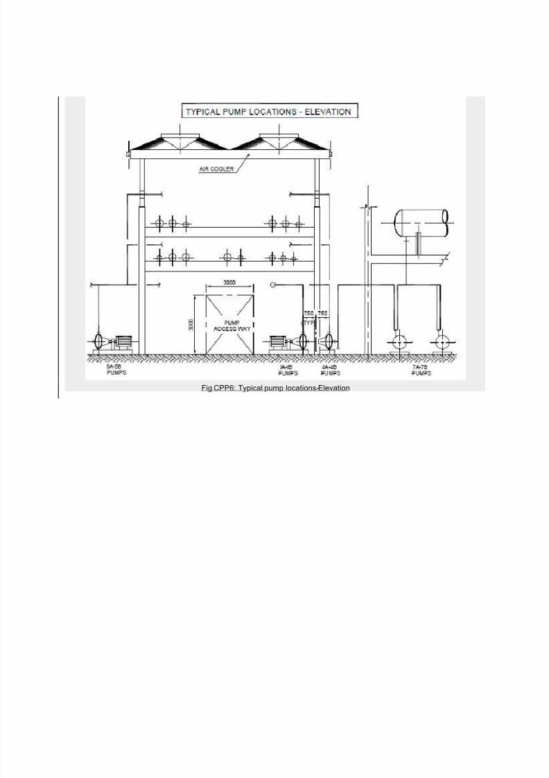
2.4 With normal piperack column spacing of 6m, it is generally found that only two pumps of average size
can be arranged between the columns, with a preferred clearance of 1m between the pumps.
The clearance between any structure / steel work and the pump discharge line shall be 0.75m minimum.
For small pumps upto 18 KW, clearance between pumps should be 0.9m minimum. A space of 2 – 2.5 m
should be provided for working aisle.
A typical arrangement of pumps is illustrated in Fig.CPP4, CPP5, CPP6.
2.5 Means of lifting should be provided for pumps or motor weighing more than 25Kg.3. Steps to do Pump Piping
Step 1 : Collect the P&ID and the pump data sheet.
Step 2 : Study the pump data sheet and collect the similar (capacity / head) pump dimensions / nozzle
position.
Step 3 : Analyse the location and the space provided in the unit plot plan w.r.t. suction and discharge line
routing.
Step 4 : Review the maintenance / operation space around and lifting facility.
Step 5 : Locate the control station, Electrical push button station, Electrical-trench, process fluid drain,
flushing / cooling connection as required for the pump model.
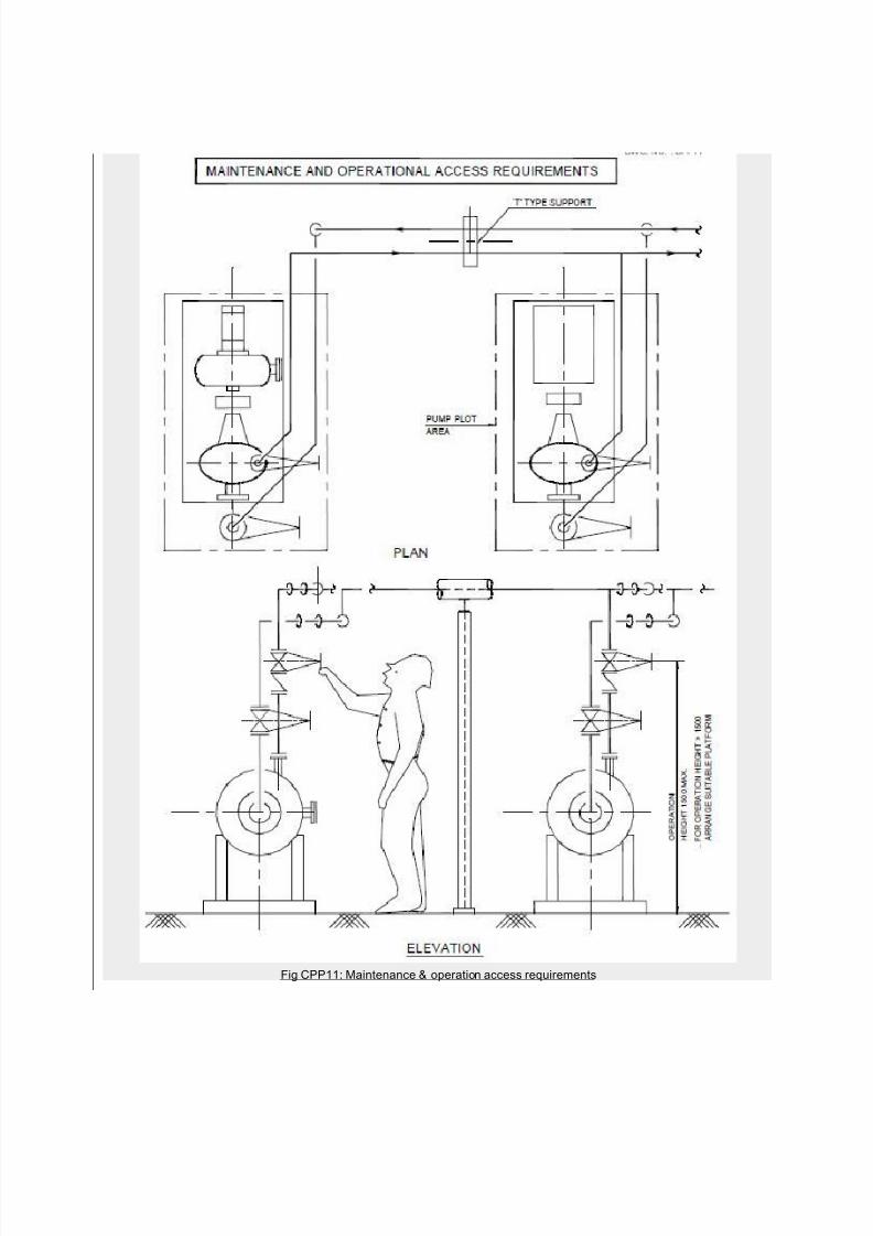
Step 6 : Check elevations of all valve handwheels on suction as well as discharge line and provide
common platform for valve operation, if required.
Step 7 : Make Iso sketch for suction and discharge line with all the items as per P&ID and discuss withprocess engineer for any change.
Step 8 : Finalise supports of the line and issue for stress analysis, if required.
Step 9 : Get the stress analysis report for Nozzle loads. Compare the allowable loads with the actual load
for any change & finalisation.
Step 10 : Finalise location of pump / drain or trench / Electrical cable route and issue civil information to
civil for foundation design.
7/27/2019 Layout Arrangement for Centrifugal Pump Piping
http://slidepdf.com/reader/full/layout-arrangement-for-centrifugal-pump-piping 3/20
Step 11 : Keep necessary insert plate on the foundation block for support of push button switch, small
lines for flushing / cooling manifold.
4. PUMP PIPING :
4.1 HORIZONTAL CENTRIFUGAL PUMP :
A typical horizontal centrifugal pump suction and discharge piping arrangements is illustrated in
Fig.CPP7.
4.2 Pump suction piping shall be as short as possible and shall be arranged so that vapour pockets are
avoided.
4.3 Reducers immediately connected to the pump suction shall be eccentric type flat side up to avoid
accumulation of gas pocket.
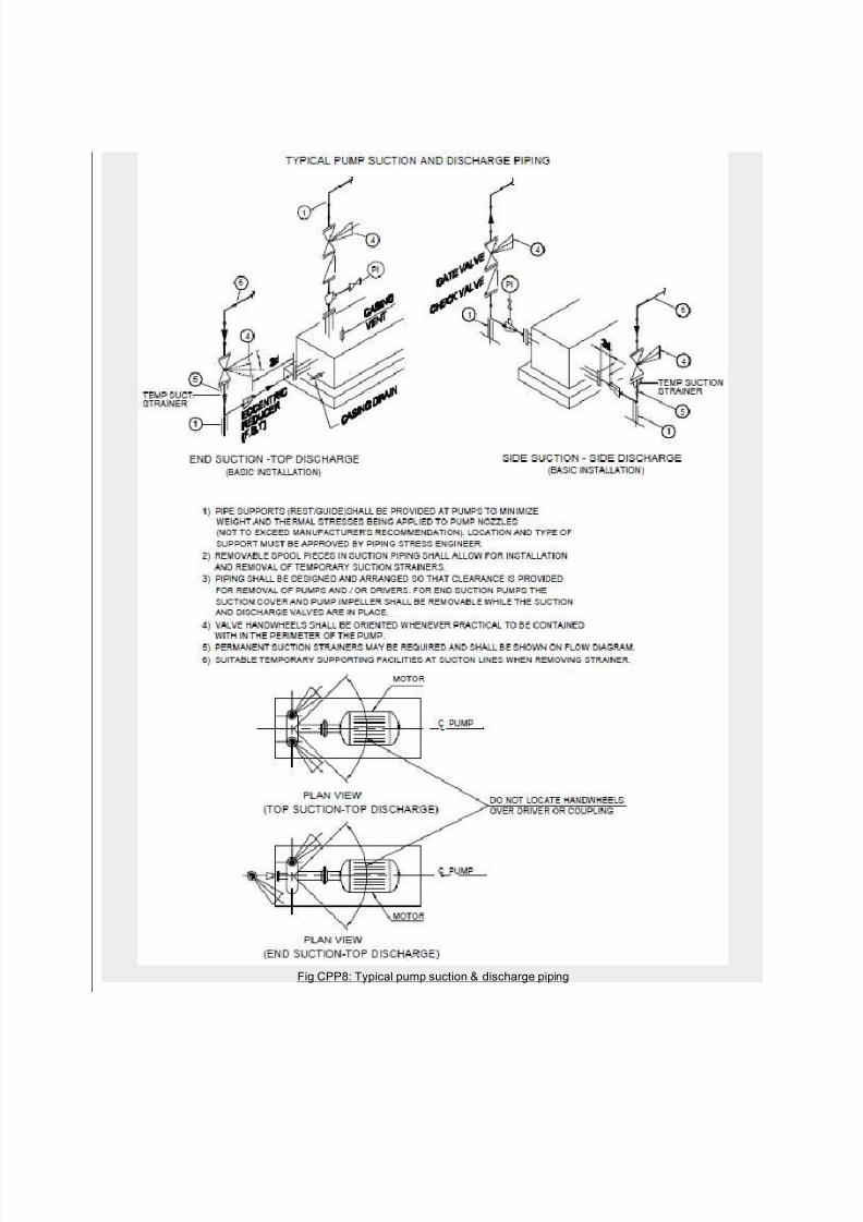
4.4 For end suction pumps, elbows shall not be directly connected to the suction flange. A straight piece
3 times the l ine size shall have to be provided at the suction nozzle. This is illustrated in Fig.CPP8.
The effect of elbow directly on suction is illustrated in Fig.CPP9.
4.5 For top suction, pump elbow shall not be directly connected to suction flange. A straight piece of
minimum 5 times the nozzle size shall have to be provided at the suction nozzle.
4.6 T-type strainers are to be used for permanent as well as temporary to avoid disassembly of suction
piping for strainer cleaning.
4.7 Piping shall be so arranged that forces and moments imposed on the pump nozzles do not exceed
the allowable values specified by the vendor.
4.8 When a suction vessel operates under vacuum the vent connection of the pump has to be
permanently connected to vapour space of the suction vessel to allow possible filling of the pump withliquid before it is started.
4.9 For pumps handling hot fluid, the first factor concerns the support of pump piping which often
includes large expansion loops for flexibility. When the pumps are located below the piperack (to reduce
possibility of hydrogen leakage over motor), support becomes easy otherwise the designer should consult
stress engineer for best location of stops and hanger. With the optimum layout and support, it is to be
ensured that the loadings on the pump nozzles are not exceeded beyond the allowable limits.
4.10 Piping configuration for a group of pumps of similar size shall follow identical pattern and the
stress analysis of one pump piping should be applicable to the other pumps.
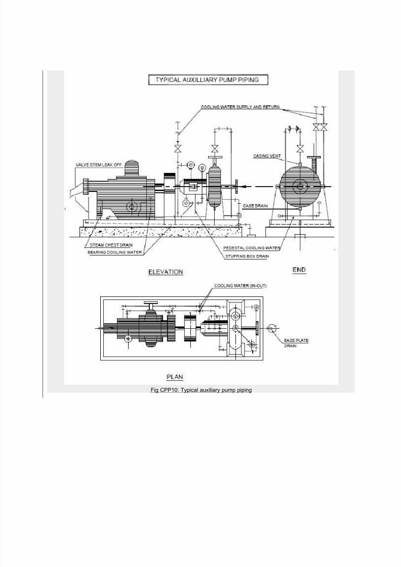
4.11 Auxiliary Pump Piping Arrangements:
The Auxiliary piping are usually cooling water to mechanical seals, bearings, stuffing boxes, gland quenchand lantern ring flush.
When pump fluid is used, a line is attached to the vent connection on the pump case. The circulated seal
fluid has to be sent back to pump stream or referred through the seal to pump internal clearances.
In viscous or high temperature hydrocarbon liquids, the seal fluid medium circulates from external source
through connections on the pump seal.
7/27/2019 Layout Arrangement for Centrifugal Pump Piping
http://slidepdf.com/reader/full/layout-arrangement-for-centrifugal-pump-piping 4/20
Various Auxiliary piping plan is recommended in API 610 for proper selection according to design
requirements.
4.12 Pump vendors usually supply the Auxiliary piping and the neat arrangements of these piping
and its support are to be ensured by the designer while reviewing the vendor document. Fig.CPP10
illustrates one typical Auxiliary piping arrangement on the pump base plate.
4.13 A typical arrangement for piping and valves operation is illustrated in Fig.CPP11 with
maintenance and operation access.
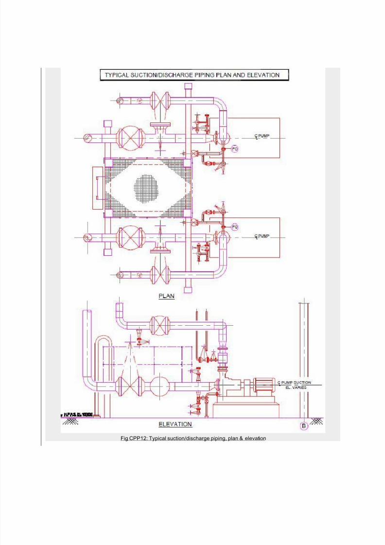
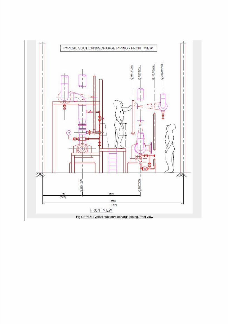
4.14 A typical suction and discharge piping arrangement with common platform for operation of
valves connected to two adjacent pumps is illustrated in Fig.CPP12 and CPP13.5. SUCTION BASIN OF PUMP
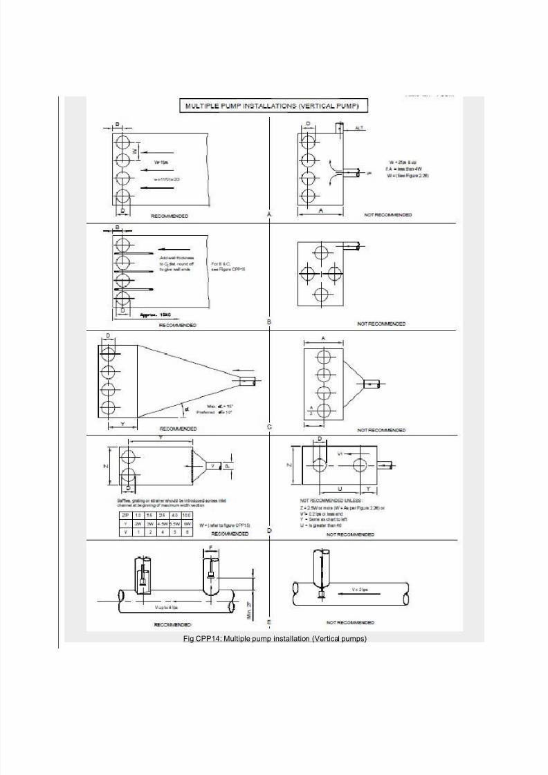
5.1 The basin for the intake of centrifugal pump shall be designed and sized properly for smooth function
of the pump. The recommendations of hydraulic institute are illustrated in Fig.CPP14.5.2 The flow of fluid to the suction bell should be even, smooth and stream lined without any vortices.
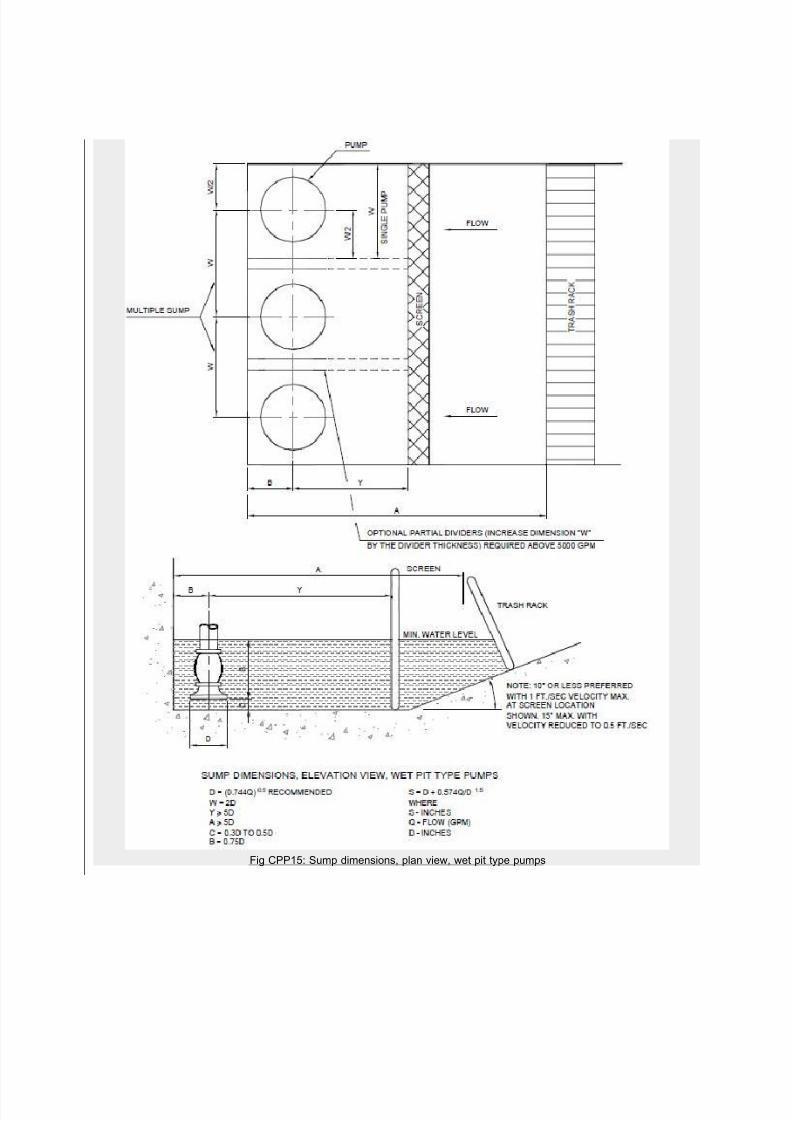
5.3 A typical sump with the components and relative dimensions of clearance and submergence is
illustrated in Fig.CPP15.
5.4 For multiple pump installations with high capacity pumps, the analysis of a proposed intake design
are often made by use of a scale model of the intake basin with all parts such as baffles, screens, gates,
separating walls etc.
The large basin is required to ensure low inlet velocity (approx. 2 ft. per sec.) and to eliminate vortexing at
the bell mouth.
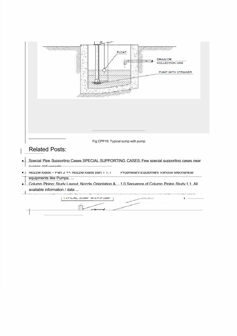
5.5 A typical sump pit with pump is illustrated in Fig CPP16. This sump is the collection pit of wastematerial coming thru a pipeline. A screen at the mouth of the pump avoids choking / fouling of the pump
during operation. The discharge of the pump may go to a slope tank / pond / waste-removal tanker.
7/27/2019 Layout Arrangement for Centrifugal Pump Piping
http://slidepdf.com/reader/full/layout-arrangement-for-centrifugal-pump-piping 5/20
Fig CPP1: Centirfugal pump drawing (Type-1)
7/27/2019 Layout Arrangement for Centrifugal Pump Piping
http://slidepdf.com/reader/full/layout-arrangement-for-centrifugal-pump-piping 6/20
Fig CPP2: Centirfugal pump drawing (Type-2)
7/27/2019 Layout Arrangement for Centrifugal Pump Piping
http://slidepdf.com/reader/full/layout-arrangement-for-centrifugal-pump-piping 7/20
Fig CPP3: Centirfugal pump drawing (Impeller)
7/27/2019 Layout Arrangement for Centrifugal Pump Piping
http://slidepdf.com/reader/full/layout-arrangement-for-centrifugal-pump-piping 8/20
Fig CPP4: Typical pump location plan
7/27/2019 Layout Arrangement for Centrifugal Pump Piping
http://slidepdf.com/reader/full/layout-arrangement-for-centrifugal-pump-piping 9/20
Fig CPP5: Typical access for Maintenance
7/27/2019 Layout Arrangement for Centrifugal Pump Piping
http://slidepdf.com/reader/full/layout-arrangement-for-centrifugal-pump-piping 10/20
Fig CPP6: Typical pump locations-Elevation
7/27/2019 Layout Arrangement for Centrifugal Pump Piping
http://slidepdf.com/reader/full/layout-arrangement-for-centrifugal-pump-piping 11/20
Fig CPP7: Air pockets in suction piping
7/27/2019 Layout Arrangement for Centrifugal Pump Piping
http://slidepdf.com/reader/full/layout-arrangement-for-centrifugal-pump-piping 12/20
Fig CPP8: Typical pump suction & discharge piping
7/27/2019 Layout Arrangement for Centrifugal Pump Piping
http://slidepdf.com/reader/full/layout-arrangement-for-centrifugal-pump-piping 13/20
Fig CPP9: Elbow at pump suction
7/27/2019 Layout Arrangement for Centrifugal Pump Piping
http://slidepdf.com/reader/full/layout-arrangement-for-centrifugal-pump-piping 14/20
Fig CPP10: Typical auxiliary pump piping
7/27/2019 Layout Arrangement for Centrifugal Pump Piping
http://slidepdf.com/reader/full/layout-arrangement-for-centrifugal-pump-piping 15/20
Fig CPP11: Maintenance & operation access requirements
7/27/2019 Layout Arrangement for Centrifugal Pump Piping
http://slidepdf.com/reader/full/layout-arrangement-for-centrifugal-pump-piping 16/20
Fig CPP12: Typical suction/discharge piping, plan & elevation
7/27/2019 Layout Arrangement for Centrifugal Pump Piping
http://slidepdf.com/reader/full/layout-arrangement-for-centrifugal-pump-piping 17/20
Fig CPP13: Typical suction/discharge piping, front view
7/27/2019 Layout Arrangement for Centrifugal Pump Piping
http://slidepdf.com/reader/full/layout-arrangement-for-centrifugal-pump-piping 18/20
Fig CPP14: Multiple pump installation (Vertical pumps)
7/27/2019 Layout Arrangement for Centrifugal Pump Piping
http://slidepdf.com/reader/full/layout-arrangement-for-centrifugal-pump-piping 19/20
Fig CPP15: Sump dimensions, plan view, wet pit type pumps
7/27/2019 Layout Arrangement for Centrifugal Pump Piping
http://slidepdf.com/reader/full/layout-arrangement-for-centrifugal-pump-piping 20/20
Fig CPP16: Typical sump with pump
Related Posts:
Special Pipe Supporting Cases SPECIAL SUPPORTING CASES: Few special supporting cases near
pumps, tall vessels ...
Nozzle loads – Part 2 << Nozzle loads part 1 1.1 Proprietary Equipment Various Mechanical
equipments like Pumps, ...
Column Piping: Study Layout, Nozzle Orientation &… 1.0 Sequence of Column Piping Study 1.1 All
available information / data ...
Underground Piping (U/G) Piping – Part 2 (adsbygoogle = window.adsbygoogle || []).push({}); While
developing &preparing the underground piping ...
Tower Piping: Center for Equipment Layout Tower Piping: Center for equipment layout A tower is
usually a ...
Google+