Embed Size (px)
Citation preview
174
Ordering Information
Description
110VAC, 1 C/O,1K to 200K Sensitivity, Draining & Filling
240VAC, 1 C/O,1K to 200K Sensitivity, Draining & Filling
400VAC, 1 C/O,1K to 200K Sensitivity, Draining & Filling
Accessories, Set Of 3 Stainless Steel Sensors
Accessories, Set Of 6 Stainless Steel Sensors
Cat. No.
4411AD1
4421AD1
4431AD1
44S0003
44S0006
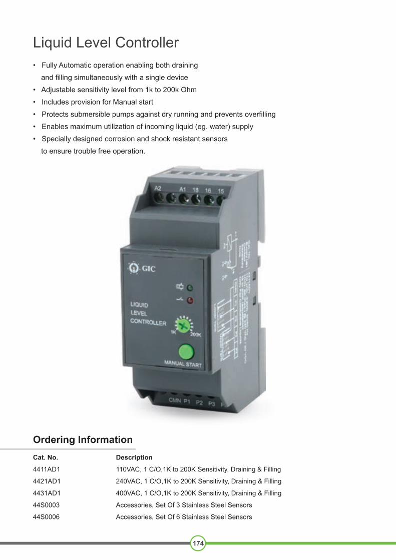
Liquid Level Controller• Fully Automatic operation enabling both draining
and filling simultaneously with a single device
• Adjustable sensitivity level from 1k to 200k Ohm
• Includes provision for Manual start
• Protects submersible pumps against dry running and prevents overfilling
• Enables maximum utilization of incoming liquid (eg. water) supply
• Specially designed corrosion and shock resistant sensors
to ensure trouble free operation.
Liquid Level Controller
175
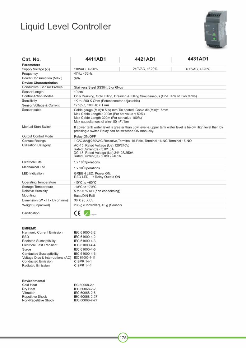
Parameters
Power Consumption (Max.)Frequency
Cat. No.
Supply Voltage ( )
4411AD1 4421AD1 4431AD1
110VAC, +/-20% 240VAC, +/-20% 400VAC, +/-20%47Hz - 63Hz3VA
Device Characteristics
Conductive Sensor Probes Stainless Steel SS304, 3 or 6Nos
Control Action ModesSensitivity
Sensor cable
Manual Start Switch
Output Control ModeContact Ratings
Only Draining, Only Filling, Draining & Filling Simultaneous (One Tank or Two tanks)1K to 200 K Ohm (Potentiometer adjustable)12 Vp-p, 100 Hz,< 1 mA
Relay ON/OFF
Sensor Voltage & Current
1 C/O,8A@250VAC,Resistive,Terminal 15-Pole, Terminal 16-NC,Terminal 18-NO
Sensor Length 10 cm
Cable gauge (Min):0.5 sq mm Tin coated, Cable dia(Min):1.5mmMax Cable Length-1000m (For set value < 50%)Max Cable Length-300m (For set value 100%)Max capacitances of wire- 80 nF / km
If Lower tank water level is greater than Low level & upper tank water level is below High level then by pressing a switch Relay can be switched ON manually.
Utilization Category
Electrical Life Mechanical Life
Operating TemperatureStorage TemperatureRelative HumidityMounting
AC-15: Rated Voltage (Ue):120/240V, Rated Current(Ie): 3.0/1.5ADC-13: Rated Voltage (Ue):24/125/250V, Rated Current(Ie): 2.0/0.22/0.1A
GREEN LED: Power ON, RED LED : Relay Output ON
-10°C to +60°C-10°C to +70°C5 to 95 % RH (non condensing)Base/DIN Rail
LED Indication
1 x 10 Operations5
1 x 10 Operations7
EMI/EMC
ESDRadiated SusceptibilityElectrical Fast TransientSurgeConducted SusceptibilityVoltage Dips & Interruptions (AC) Conducted Emission
IEC 61000-3-2 IEC 61000-4-2 IEC 61000-4-3 IEC 61000-4-4 IEC 61000-4-5 IEC 61000-4-6 IEC 61000-4-11 CISPR 14-1
Harmonic Current Emission
Radiated Emission CISPR 14-1
Environmental Cold Heat
Non-Repetitive Shock
Dry HeatVibrationRepetitive Shock
IEC 60068-2-2 IEC 60068-2-6 IEC 60068-2-27 IEC 60068-2-27
EC 60068-2-1
CertificationRoHS Compliant
Dimension (W x H x D) (in mm)Weight (unpacked)
36 X 90 X 65235 g (Controller), 45 g (Sensor)
IN
OUT OUT OUT
ON
OUT OUT OUT OFFOUT
ON
OFF
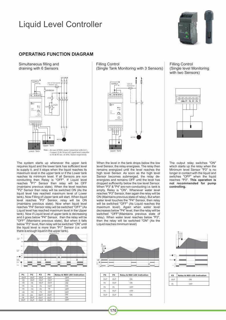
P1 P2 P3 P4 Relay & RED LED Indication
OUT OUT OUT OUT
OUT OUT OUT
OUT OUT
OUT
IN
IN
IN
IN
IN
IN
IN
IN
IN
IN
IN
IN
IN
IN
IN
OUT
OUT
OUT
ON
ON
OFF
OFF
OFF
ONA2
A1
Relay
181516
Relay
SwitchMAN
P1Lower Tank
P2
CMN
CMN
P3
P4DRAINING & FILLING
Upper Tank
Lower Tank
N
LSUPPLY
Coil of Contactor / Starter coil
BYPASS
AUTO
L1 L2L3
STOP
START
MOTOR
A2 A1 18 16 15
GIC
1K
LIQUIDLEVELCONTROLLER
P4P3P2P1CMN
Simultaneous filling and draining with 6 Sensors
Upper Tank
200K
Note :- In case of DOL starter connection with LLC, Connect 15 & 18 nos of Liquid level controller to 93 & 95 nos. of DOL Starter respectively
ON
P4P3 Relay & RED LED Indication
OUT
IN
OUT
OUT
OUT
IN
IN
IN
OFF
OFF
ON
ON
OUT
OUT
SWITCHMAN
RELAY
ON
CO
M
P4
P3
1615
18
A2A1
A2 A1 18 16 15
P4P3P2P1CMN
Filling Control (Single Tank Monitoring with 3 Sensors)
MOTOR
N
L
GIC
1K 200K
Upper Tank
LIQUID
LEVEL
CONTROLLER
N L
SUPPLY Coil of Contactor
N LN LN LN LN LN LN L
Filling Control (Single level Monitoring with two Sensors)
P4P3P2P1CMN
1615
18
RELAY
ONA2A1
P3
P4
CO
M
P3
OUT
IN
Relay & RED LED Indication
OFF
ON
OPERATING FUNCTION DIAGRAM
The system starts up whenever the upper tank requires liquid and the lower tank has sufficient level to supply it, and it stops when the liquid reaches its maximum level in the upper tank or if the Lower tank reaches its minimum level. If all Sensors are non conducting then Relay is "OFF''. If Liquid level reaches "P1" Sensor then relay will be OFF (maintains previous state). When the level reaches "P2" Sensor then relay will be switched ON (As the liquid level has reached maximum level of Lower tank). Now Filling of Upper tank will start. When liquid level reaches "P3" Sensor, relay will be ON (maintains previous state). Now when liquid level reaches "P4" Sensor relay will be switched "OFF" (As Liquid level has reached maximum level in the Upper tank). Now if Liquid level of upper tank is decreasing and it goes below "P4" Sensor, then the relay will be "OFF" (Maintains previous state), But when it falls below "P3" level, then relay will be switched "ON" until the liquid level is more than "P1" Sensor (i.e. until there is enough liquid in the upper tank).
When the level in the tank drops below the low level Sensor, the relay energises. The relay then remains energized until the level reaches the high level Sensor. As soon as the high level Sensor becomes submerged, the relay de-energizes and remains OFF until the level has dropped sufficiently below the low level Sensor. When "P3" & "P4" are non-conducting i.e. tank is empty, Relay is "ON". Whenever water level reaches "P3" Sensor, then again the relay will be ON (Maintains previous state of relay). But when water level touches the "P4" Sensor, then relay will be switched "OFF" (As Liquid reaches the maximum level). Again when water level decreases below "P4" level, then the relay will be switched "OFF"(Maintains previous state of relay). When water level reaches below "P3", then the relay will be switched "ON" (As the Liquid reaches minimum level)
The output relay switches "ON" which starts up the relay when the Minimum level Sensor "P3" is no longer in contact with the liquid and switches "OFF" when the liquid reaches "P3". This operation is not recommended for pump controlling.
Liquid Level Controller
176

Draining Control (Single Tank Monitoring with 3 Sensors)
Draining Control (Single level Monitoring with two Sensors)
OPERATING FUNCTION DIAGRAM
MOTOR
N
L
A2 A1 18 16 15
P4P3P2P1CMN
GIC
1K 200K
LIQUIDLEVELCONTROLLER
Lower Tank
Coil of Contactor
SUPPLY
N L
OFF
P2P1 Relay & RED LED Indication
OUT
IN
OUT
OUT
OUT
IN
IN
IN
ON
ON
OFF
OFF
OUT
OUT
RELAY
ON
CO
M
1615
18SWITCHMAN
A2A1
P1P2
1615
18
RELAY
ONA2A1
P1
P2
CO
M
P1
OUT
IN
Relay & RED LED Indication
OFF
ON
P4P3P2P1CMN
Liquid Level Controller
177
When the level in the tank rises sufficiently to submerge the high level Sensor, the relay energizes. The relay then remains energized until the level has dropped below the low level Sensor. As the liquid drops below the low level Sensor, the relay de-energizes and remains off until the level has risen sufficiently to submerge the high level Sensor. When "P1" & "P2" are non-conducting i.e. when the tank is empty, relay is "OFF". Whenever water level reaches "P1" Sensor, then again the relay will be "OFF" (maintains previous state of relay). But when water level touches the "P2" Sensor, then relay will be switched "ON" (as the Liquid reaches maximum level). Again, when water level decreases below "P2" level, then the relay will remain switched "ON" (maintains previous state of relay). When water level reaches below "P1", then relay will be switched "OFF" (as the liquid reaches minimum level).
The output relay switches ON, when liquid level goes above a maximum level, fixed by the Sensor "P1", when the level drops below a "P1" Sensor, relay switches "OFF". This operation is not recommended for pump controlling.
Liquid Level Controller
178
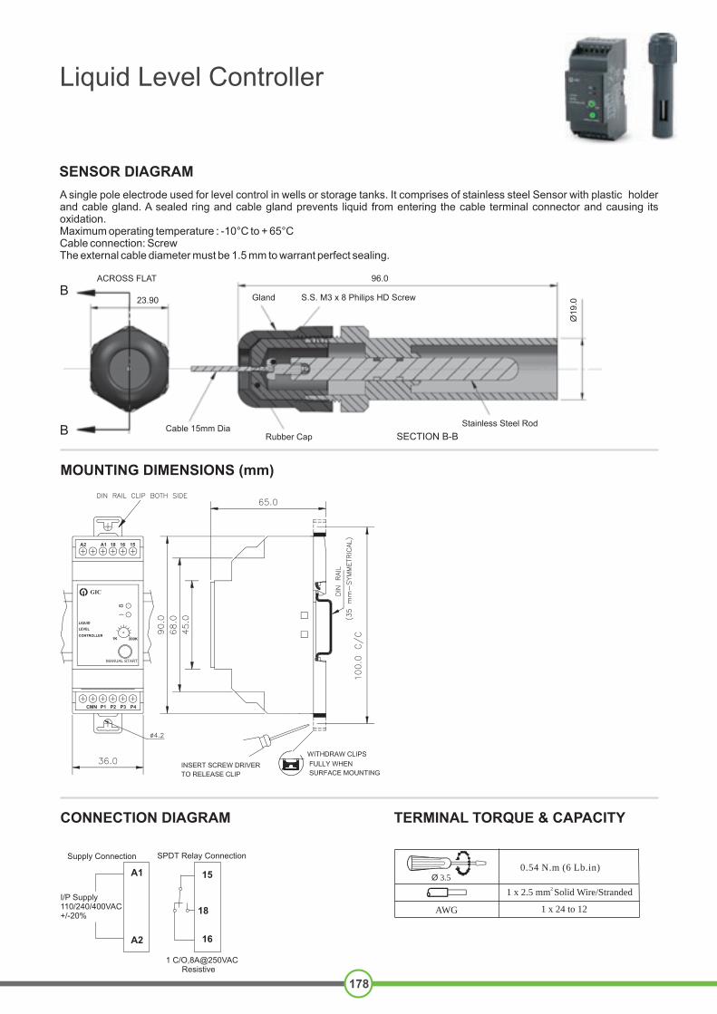
MOUNTING DIMENSIONS (mm)
SENSOR DIAGRAM
CONNECTION DIAGRAM TERMINAL TORQUE & CAPACITY
A single pole electrode used for level control in wells or storage tanks. It comprises of stainless steel Sensor with plastic holder and cable gland. A sealed ring and cable gland prevents liquid from entering the cable terminal connector and causing its oxidation. Maximum operating temperature : -10°C to + 65°CCable connection: Screw The external cable diameter must be 1.5 mm to warrant perfect sealing.
A2 A1 18 16 15
P4P3P2P1CMN
GIC
LIQUID
LEVEL
CONTROLLER1K 200K
Supply Connection SPDT Relay Connection
1 C/O,8A@250VAC Resistive
I/P Supply110/240/400VAC+/-20%
A1
A2
15
18
16
ACROSS FLAT 96.0
23.90 Gland S.S. M3 x 8 Philips HD Screw
Cable 15mm DiaRubber Cap
Stainless Steel RodSECTION B-B
Ø19
.0
B
B
Ø 3.5
AWG
0.54 N.m (6 Lb.in)
2 1 x 2.5 mm Solid Wire/Stranded
1 x 24 to 12