Embed Size (px)
Citation preview
TI401F/00/en
Technical Information
Liquicap M FMI51, FMI52
Capacitive Level Measurement
For continuous measurement in liquids
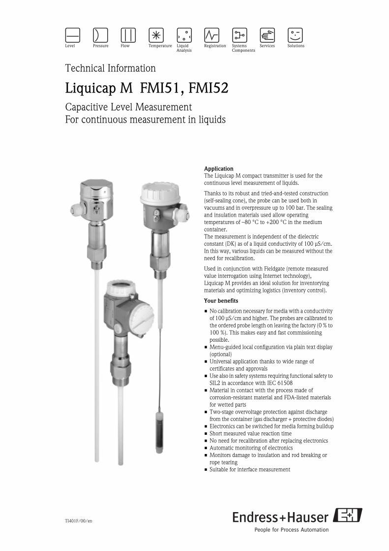
Application
The Liquicap M compact transmitter is used for the
continuous level measurement of liquids.
Thanks to its robust and tried-and-tested construction
(self-sealing cone), the probe can be used both in
vacuums and in overpressure up to 100 bar. The sealing
and insulation materials used allow operating
temperatures of –80 °C to +200 °C in the medium
container.
The measurement is independent of the dielectric
constant (DK) as of a liquid conductivity of 100 μS/cm.
In this way, various liquids can be measured without the
need for recalibration.
Used in conjunction with Fieldgate (remote measured
value interrogation using Internet technology),
Liquicap M provides an ideal solution for inventorying
materials and optimizing logistics (inventory control).
Your benefits
• No calibration necessary for media with a conductivity
of 100 μS/cm and higher. The probes are calibrated to
the ordered probe length on leaving the factory (0 % to
100 %). This makes easy and fast commissioning
possible.
• Menu-guided local configuration via plain text display
(optional)
• Universal application thanks to wide range of
certificates and approvals
• Use also in safety systems requiring functional safety to
SIL2 in accordance with IEC 61508
• Material in contact with the process made of
corrosion-resistant material and FDA-listed materials
for wetted parts
• Two-stage overvoltage protection against discharge
from the container (gas discharger + protective diodes)
• Electronics can be switched for media forming buildup
• Short measured value reaction time
• No need for recalibration after replacing electronics
• Automatic monitoring of electronics
• Monitors damage to insulation and rod breaking or
rope tearing
• Suitable for interface measurement
Liquicap M FMI51, FMI52
2 Endress+Hauser
Table of contents
Function and system design. . . . . . . . . . . . . . . . . . . . . 3
Measuring principle . . . . . . . . . . . . . . . . . . . . . . . . . . . . . . . . . . . 3
Measuring system . . . . . . . . . . . . . . . . . . . . . . . . . . . . . . . . . . . . . 4
System integration via Fieldgate . . . . . . . . . . . . . . . . . . . . . . . . . . 6
Operating conditions: Installation . . . . . . . . . . . . . . . . 7
Installation instructions . . . . . . . . . . . . . . . . . . . . . . . . . . . . . . . . . 7
With separate housing . . . . . . . . . . . . . . . . . . . . . . . . . . . . . . . . . 8
Operating conditions: Environment. . . . . . . . . . . . . . . 9
Ambient temperature range . . . . . . . . . . . . . . . . . . . . . . . . . . . . . 9
Storage temperature . . . . . . . . . . . . . . . . . . . . . . . . . . . . . . . . . . . 9
Degree of protection . . . . . . . . . . . . . . . . . . . . . . . . . . . . . . . . . . . 9
Climate class . . . . . . . . . . . . . . . . . . . . . . . . . . . . . . . . . . . . . . . 10
Vibration resistance . . . . . . . . . . . . . . . . . . . . . . . . . . . . . . . . . . 10
Cleaning . . . . . . . . . . . . . . . . . . . . . . . . . . . . . . . . . . . . . . . . . . 10
Electromagnetic compatibility (EMC) . . . . . . . . . . . . . . . . . . . . . 10
Shock resistance . . . . . . . . . . . . . . . . . . . . . . . . . . . . . . . . . . . . 10
Operating conditions: Process . . . . . . . . . . . . . . . . . . 10
Process temperature range . . . . . . . . . . . . . . . . . . . . . . . . . . . . . 10
Pressure and temperature derating . . . . . . . . . . . . . . . . . . . . . . . 11
Process pressure limits . . . . . . . . . . . . . . . . . . . . . . . . . . . . . . . . 12
State of aggregation . . . . . . . . . . . . . . . . . . . . . . . . . . . . . . . . . . 13
Mechanical construction . . . . . . . . . . . . . . . . . . . . . . 14
Overview . . . . . . . . . . . . . . . . . . . . . . . . . . . . . . . . . . . . . . . . . . 14
Technical data (probe) . . . . . . . . . . . . . . . . . . . . . . . . . . . . . . . . 20
Weight . . . . . . . . . . . . . . . . . . . . . . . . . . . . . . . . . . . . . . . . . . . . 20
Material . . . . . . . . . . . . . . . . . . . . . . . . . . . . . . . . . . . . . . . . . . . 20
Input . . . . . . . . . . . . . . . . . . . . . . . . . . . . . . . . . . . . . 21
Measured variable . . . . . . . . . . . . . . . . . . . . . . . . . . . . . . . . . . . 21
Measuring range with electronic insert
FEI50H (4 to 20 mA HART)
FEI57C (PFM) . . . . . . . . . . . . . . . . . . . . . . . . . . . . . . . . . . . . . . 21
Input signal . . . . . . . . . . . . . . . . . . . . . . . . . . . . . . . . . . . . . . . . 21
Measuring condition . . . . . . . . . . . . . . . . . . . . . . . . . . . . . . . . . . 21
Output . . . . . . . . . . . . . . . . . . . . . . . . . . . . . . . . . . . . 22
Output signal . . . . . . . . . . . . . . . . . . . . . . . . . . . . . . . . . . . . . . 22
Signal on alarm . . . . . . . . . . . . . . . . . . . . . . . . . . . . . . . . . . . . . 22
Linearization . . . . . . . . . . . . . . . . . . . . . . . . . . . . . . . . . . . . . . . 22
Power supply. . . . . . . . . . . . . . . . . . . . . . . . . . . . . . . 23
Electrical connection . . . . . . . . . . . . . . . . . . . . . . . . . . . . . . . . . 23
Terminal assignment . . . . . . . . . . . . . . . . . . . . . . . . . . . . . . . . . 23
Connector . . . . . . . . . . . . . . . . . . . . . . . . . . . . . . . . . . . . . . . . . 24
Supply voltage . . . . . . . . . . . . . . . . . . . . . . . . . . . . . . . . . . . . . . 24
Cable entry . . . . . . . . . . . . . . . . . . . . . . . . . . . . . . . . . . . . . . . . 24
Power consumption . . . . . . . . . . . . . . . . . . . . . . . . . . . . . . . . . . 24
Current consumption . . . . . . . . . . . . . . . . . . . . . . . . . . . . . . . . . 25
HART residual ripple . . . . . . . . . . . . . . . . . . . . . . . . . . . . . . . . . 25
HART noise (FEI50H) . . . . . . . . . . . . . . . . . . . . . . . . . . . . . . . . . 25
Performance characteristics. . . . . . . . . . . . . . . . . . . . 25
Reference operating conditions . . . . . . . . . . . . . . . . . . . . . . . . . . 25
Maximum measured error . . . . . . . . . . . . . . . . . . . . . . . . . . . . . 25
Influence of ambient temperature . . . . . . . . . . . . . . . . . . . . . . . . 25
Startup settling time . . . . . . . . . . . . . . . . . . . . . . . . . . . . . . . . . . 25
Measured value reaction time . . . . . . . . . . . . . . . . . . . . . . . . . 25
Integration time . . . . . . . . . . . . . . . . . . . . . . . . . . . . . . . . . . . . . 26
Accuracy of factory calibration. . . . . . . . . . . . . . . . . . . . . . . . . . 26
Resolution . . . . . . . . . . . . . . . . . . . . . . . . . . . . . . . . . . . . . . . . . 26
Human interface . . . . . . . . . . . . . . . . . . . . . . . . . . . . 27
Electronic inserts . . . . . . . . . . . . . . . . . . . . . . . . . . . . . . . . . . . . 27
Operating concept with FEI50H display (optional) . . . . . . . . . . . 27
Display (optional) . . . . . . . . . . . . . . . . . . . . . . . . . . . . . . . . . . . . 27
Local operation . . . . . . . . . . . . . . . . . . . . . . . . . . . . . . . . . . . . . 28
Remote operation . . . . . . . . . . . . . . . . . . . . . . . . . . . . . . . . . . . . 29
Certificates and approvals . . . . . . . . . . . . . . . . . . . . . 30
CE mark . . . . . . . . . . . . . . . . . . . . . . . . . . . . . . . . . . . . . . . . . . 30
Ex approval . . . . . . . . . . . . . . . . . . . . . . . . . . . . . . . . . . . . . . . . 30
Other standards and guidelines . . . . . . . . . . . . . . . . . . . . . . . . . . 30
Ordering information. . . . . . . . . . . . . . . . . . . . . . . . . 30
Liquicap M FMI51 . . . . . . . . . . . . . . . . . . . . . . . . . . . . . . . . . . 30
Liquicap M FMI52 . . . . . . . . . . . . . . . . . . . . . . . . . . . . . . . . . . 34
Accessories . . . . . . . . . . . . . . . . . . . . . . . . . . . . . . . . 37
Protective cover . . . . . . . . . . . . . . . . . . . . . . . . . . . . . . . . . . . . . 37
Shortening kit for FMI52 . . . . . . . . . . . . . . . . . . . . . . . . . . . . . . 37
Commubox FXA191, FXA195 HART . . . . . . . . . . . . . . . . . . . . . 37
Surge arrester HAW569 . . . . . . . . . . . . . . . . . . . . . . . . . . . . . . . 37
Weld-in adapter for universal adapter . . . . . . . . . . . . . . . . . . . . . 38
Weld-in adapter for G ¾ . . . . . . . . . . . . . . . . . . . . . . . . . . . . . . 38
Weld-in adapter for G 1 . . . . . . . . . . . . . . . . . . . . . . . . . . . . . . . 38
Spare parts . . . . . . . . . . . . . . . . . . . . . . . . . . . . . . . . . . . . . . . . . 38
Supplementary Documentation . . . . . . . . . . . . . . . . . 39
Technical Information . . . . . . . . . . . . . . . . . . . . . . . . . . . . . . . . 39
Operating Instructions . . . . . . . . . . . . . . . . . . . . . . . . . . . . . . . . 39
Certificates . . . . . . . . . . . . . . . . . . . . . . . . . . . . . . . . . . . . . . . . 39
Patents . . . . . . . . . . . . . . . . . . . . . . . . . . . . . . . . . . . . . . . . . . . 40
Liquicap M FMI51, FMI52
Endress+Hauser 3
Function and system design
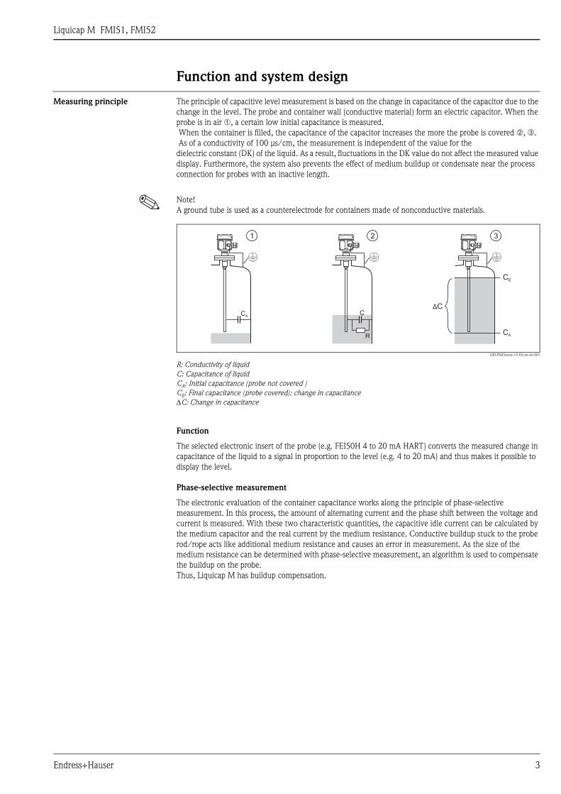
Measuring principle The principle of capacitive level measurement is based on the change in capacitance of the capacitor due to the
change in the level. The probe and container wall (conductive material) form an electric capacitor. When the
probe is in air ➀, a certain low initial capacitance is measured.
When the container is filled, the capacitance of the capacitor increases the more the probe is covered ➁, ➂.
As of a conductivity of 100 μs/cm, the measurement is independent of the value for the
dielectric constant (DK) of the liquid. As a result, fluctuations in the DK value do not affect the measured value
display. Furthermore, the system also prevents the effect of medium buildup or condensate near the process
connection for probes with an inactive length.
! Note!
A ground tube is used as a counterelectrode for containers made of nonconductive materials.
L00-FMI5xxxx-15-05-xx-xx-001
R: Conductivity of liquid
C: Capacitance of liquid
CA: Initial capacitance (probe not covered )
CE: Final capacitance (probe covered): change in capacitance
ΔC: Change in capacitance
Function
The selected electronic insert of the probe (e.g. FEI50H 4 to 20 mA HART) converts the measured change in
capacitance of the liquid to a signal in proportion to the level (e.g. 4 to 20 mA) and thus makes it possible to
display the level.
Phase-selective measurement
The electronic evaluation of the container capacitance works along the principle of phase-selective
measurement. In this process, the amount of alternating current and the phase shift between the voltage and
current is measured. With these two characteristic quantities, the capacitive idle current can be calculated by
the medium capacitor and the real current by the medium resistance. Conductive buildup stuck to the probe
rod/rope acts like additional medium resistance and causes an error in measurement. As the size of the
medium resistance can be determined with phase-selective measurement, an algorithm is used to compensate
the buildup on the probe.
Thus, Liquicap M has buildup compensation.
CA
R
C
CE
1 2 3
CA
ÄC
Liquicap M FMI51, FMI52
4 Endress+Hauser
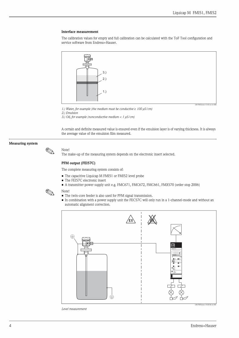
Interface measurement
The calibration values for empty and full calibration can be calculated with the ToF Tool configuration and
service software from Endress+Hauser.
L00-FMI5xxxx-15-05-xx-xx-000
1.) Water, for example (the medium must be conductive ≥ 100 μS/cm)
2.) Emulsion
3.) Oil, for example (nonconductive medium < 1 μS/cm)
A certain and definite measured value is ensured even if the emulsion layer is of varying thickness. It is always
the average value of the emulsion film measured.
Measuring system
! Note!
The make-up of the measuring system depends on the electronic insert selected.
PFM output (FEI57C)
The complete measuring system consists of:
• The capacitive Liquicap M FMI51 or FMI52 level probe
• The FEI57C electronic insert
• A transmitter power supply unit e.g. FMC671, FMC672, FMC661, FMX570 (order stop 2006)
! Note!
• The twin-core feeder is also used for PFM signal transmission.
• In combination with a power supply unit the FEC57C will only run in a 1-channel-mode and without an
automatic alignment correction.
L00-FMI5xxxx-14-00-06-xx-001
Level measurement
1.)
2.)
3.)
EX EX
FMC671Z
Liquicap M FMI51, FMI52
Endress+Hauser 5
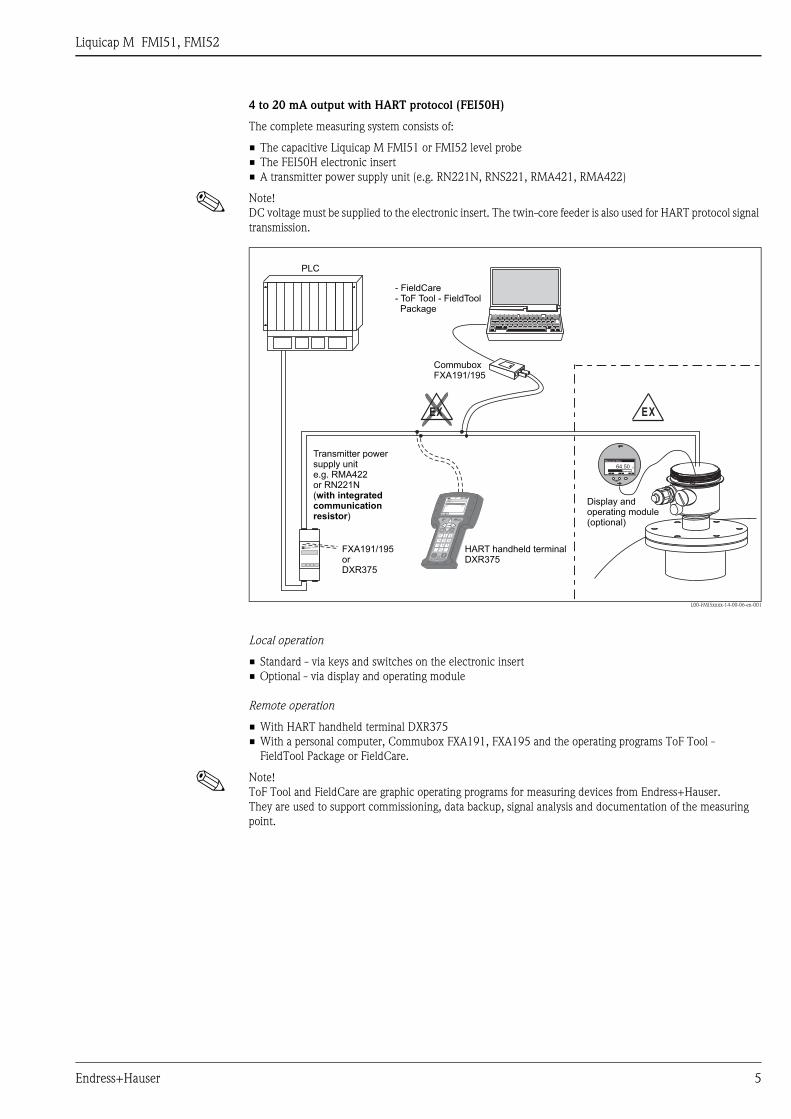
4 to 20 mA output with HART protocol (FEI50H)
The complete measuring system consists of:
• The capacitive Liquicap M FMI51 or FMI52 level probe
• The FEI50H electronic insert
• A transmitter power supply unit (e.g. RN221N, RNS221, RMA421, RMA422)
! Note!
DC voltage must be supplied to the electronic insert. The twin-core feeder is also used for HART protocol signal
transmission.
L00-FMI5xxxx-14-00-06-en-001
Local operation
• Standard - via keys and switches on the electronic insert
• Optional - via display and operating module
Remote operation
• With HART handheld terminal DXR375
• With a personal computer, Commubox FXA191, FXA195 and the operating programs ToF Tool -
FieldTool Package or FieldCare.
! Note!
ToF Tool and FieldCare are graphic operating programs for measuring devices from Endress+Hauser.
They are used to support commissioning, data backup, signal analysis and documentation of the measuring
point.
ENDRESS + HAUSERRMA 422
1# % &
Copy
G H I
P Q R S
, ( ) ‘
A B C
Paste
PageOn
PageUp
DeleteBksp
Insert
J K L
T U V
_ < >
D E F
Hot Key
+ Hot Key
M N O
W X Y Z
+ * /
4
7
.
2
5
8
0
375FIELD COMMUNICATOR
3
6
9
-
DELTABAR: * * * * * * * *ONLINE
1 QUICK SETUP2 OPERATING MENU
4 SV 0 °C3 PV 352 mbar
HELP SAVE
dsdmdmdf das.
asdas faasas la.
EXEX
64.50 %
+ ↵
Measured Value
HART handheld terminalDXR375
PLC
CommuboxFXA191/195
Displayperating
ando module(optional)
- FieldCare- ToF Tool - FieldToolPackage
64.50 %
+ ↵
Measured Value
FXA191/195orDXR375
Transmitter powersupply unite.g. RMA422or RN221N(
)
with integratedcommunicationresistor
Liquicap M FMI51, FMI52
6 Endress+Hauser
System integration via
Fieldgate
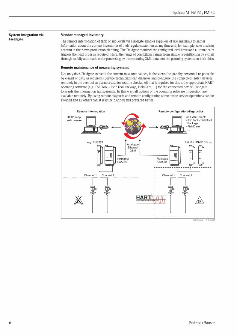
Vendor managed inventory
The remote interrogation of tank or silo levels via Fieldgate enables suppliers of raw materials to gather
information about the current inventories of their regular customers at any time and, for example, take this into
account in their own production planning. The Fieldgate monitors the configured level limits and automatically
triggers the next order as required. Here, the range of possibilities ranges from simple requisitioning by e-mail
through to fully automatic order processing by incorporating XML data into the planning systems on both sides.
Remote maintenance of measuring systems
Not only does Fieldgate transmit the current measured values, it also alerts the standby personnel responsible
by e-mail or SMS as required.- Service technicians can diagnose and configure the connected HART devices
remotely in the event of an alarm or also for routine checks. All that is required for this is the appropriate HART
operating software (e.g. ToF Tool - FieldTool Package, FieldCare, ...) for the connected device. Fieldgate
forwards the information transparently. In this way, all options of the operating software in question are
available remotely. By using remote diagnosis and remote configuration some onsite service operations can be
avoided and all others can at least be planned and prepared better.
L00-FMI5xxxx-14-00-06-en-002
-.
FieldgateFXA320
FieldgateFXA520
ENDRESS+HAUSERRN 221N
ENDRESS+HAUSERRN 221N
HTTP scriptweb browser…
AnalogueEthernet
GSM
e.g. 2 x RN221N-B …e.g. RNS221
Channel 1 Channel 1Channel 2 Channel 2
via HART client:- ToF Tool - FieldToolPackage
- FieldCare. . .
Remote interrogation Remote configuration/diagnostics
Liquicap M FMI51, FMI52
Endress+Hauser 7
Operating conditions: Installation
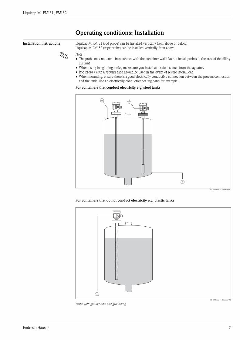
Installation instructions Liquicap M FMI51 (rod probe) can be installed vertically from above or below.
Liquicap M FMI52 (rope probe) can be installed vertically from above.
! Note!
• The probe may not come into contact with the container wall! Do not install probes in the area of the filling
curtain!
• When using in agitating tanks, make sure you install at a safe distance from the agitator.
• Rod probes with a ground tube should be used in the event of severe lateral load.
• When mounting, ensure there is a good electrically conductive connection between the process connection
and the tank. Use an electrically conductive sealing band for example.
For containers that conduct electricity e.g. steel tanks
L00-FMI5xxxx-11-06-xx-xx-001
For containers that do not conduct electricity e.g. plastic tanks
L00-FMI5xxxx-11-06-xx-xx-002
Probe with ground tube and grounding
Liquicap M FMI51, FMI52
8 Endress+Hauser
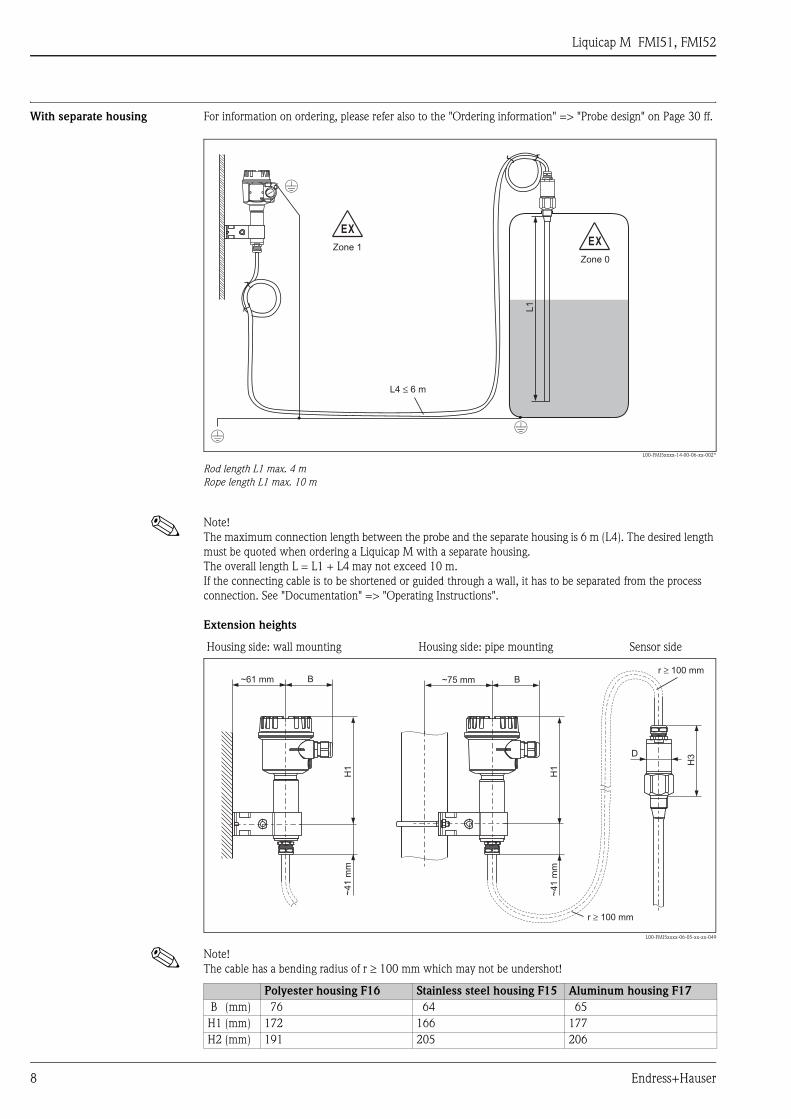
With separate housing For information on ordering, please refer also to the "Ordering information" => "Probe design" on Page 30 ff.
L00-FMI5xxxx-14-00-06-xx-002*
Rod length L1 max. 4 m
Rope length L1 max. 10 m
! Note!
The maximum connection length between the probe and the separate housing is 6 m (L4). The desired length
must be quoted when ordering a Liquicap M with a separate housing.
The overall length L = L1 + L4 may not exceed 10 m.
If the connecting cable is to be shortened or guided through a wall, it has to be separated from the process
connection. See "Documentation" => "Operating Instructions".
Extension heights
! Note!
The cable has a bending radius of r ≥ 100 mm which may not be undershot!
EX
Zone 1
L4 6 m≤
EX
Zone 0
L1
Housing side: wall mounting Housing side: pipe mounting Sensor side
L00-FMI5xxxx-06-05-xx-xx-049
~61 mm ~75 mm
~4
1m
m
~4
1m
m
BB
H1
H1
H3D
r 100 mm≥
r 100 mm≥
Polyester housing F16 Stainless steel housing F15 Aluminum housing F17
B (mm) 76 64 65
H1 (mm) 172 166 177
H2 (mm) 191 205 206

Liquicap M FMI51, FMI52
Endress+Hauser 9
Rod probes, rope probes
! Note!
Connecting cable: ø10.5 mm
Outer jacket: silicone, mechanical resistance
Wall holder unit
L00-FMI5xxxx-06-05-xx-xx-065
Note that the wall holder unit first has to be screwed to the separate housing before you can use it as a drilling template.
The distance between the holes is reduced by screwing it to the separate housing.
Operating conditions: Environment
Ambient temperature range • Ambient temperature of the transmitter: –50 °C to +70 °C (observe derating; see Page 10 ff. With WHG
approval restriction on – 40 °C).
• At Ta < –20 °C and Ta > +60 °C, the functionality of the LCD display is limited.
• A weather protection cover should be used when operating outdoors in strong sunlight. For further
information on the protective cover, see Page 37
Storage temperature • –50 °C to +85 °C
Degree of protection As per EN60529
bar D (mm) H3 (mm)
G½, G¾, G1,
NPT½, NPT¾, NPT1
25 ø38 103
Clamp 1, 1½ 16 ø38 122
bar D (mm) H3 (mm)
G1½,
NPT1½
100 ø50 130
Clamp 1½ 16 ø50 137
Clamp 2 16 ø50 156
6.2
mm
6.2
mm
28
mm
28
mm
86 mm86 mm+1.1+1.1–0.8–0.8
70 mm70 mm+1.2+1.2–0.8–0.83 mm3 mm
IP66 IP67 IP68 NEMA4X
Polyester housing F16 X X - X
Stainless steel housing F15 X X - X
Aluminum housing F17 X X - X
Aluminum housing F13
with gas-tight process seal
X - X X
Aluminum housing T13
with gas-tight process seal and
separate connection compartment (EEx d)
X - X X
Separate housing X X X
Liquicap M FMI51, FMI52
10 Endress+Hauser
Climate class • DIN EN 60068-2-38/IEC 68-2-38: test Z/AD
Vibration resistance DIN EN 60068-2-64/IEC 68-2-64: 20 to 2000 Hz, 1 (m/s2)2/Hz
Cleaning Housing:
When cleaning, make sure that the cleaning agent used does not attack or corrode the housing surface or seals.
Probe:
Depending on the application, buildup (contamination and soiling) can form on the probe rod. A high degree
of material buildup can affect the measurement result. If the medium tends to create a high degree of buildup,
regular cleaning is recommended. When cleaning, it is important to make sure that the insulation of the probe
rod is not damaged. If cleaning agents are used make sure the material is resistant to them!
Electromagnetic compatibility
(EMC)
• Interference emission to EN 61326, Electrical Equipment Class B
Interference immunity to EN 61326, Annex A (Industrial) and NAMUR Recommendation NE 21 (EMC)
• If only the analog signal is to be used, a usual commercial instrument cable is sufficient. If the superimposed
communication signal (HART 4 to 20 mA) is used, a shielded cable must be used.
• A usual commercial cable can be used for PFM.
Shock resistance DIN EN 60068-2-27/IEC 68-2-27: 30g acceleration
Operating conditions: Process
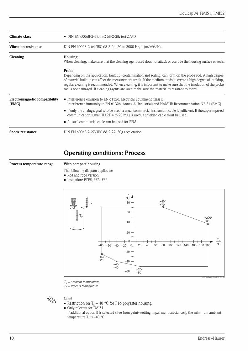
Process temperature range With compact housing
The following diagram applies to:
• Rod and rope version
• Insulation: PTFE, PFA, FEP
L00-FMI5xxxx-05-05-xx-xx-013
Ta = Ambient temperature
TP = Process temperature
! Note!
• Restriction on Ta – 40 °C for F16 polyester housing.• Only relevant for FMI51!
If additional option B is selected (free from paint-wetting impairment substances), the minimum ambient
temperature Ta is –40 °C.
Ta
0
0
TP
–40 –20–60 80 120 160 180
80
60
40
20
–80
–80/–25
200
–60
–40
–20
20 40 60 100 140
–40/–40
+20/–50
+200/+38
+80/+70
TP
Ta
°C
°C
Liquicap M FMI51, FMI52
Endress+Hauser 11
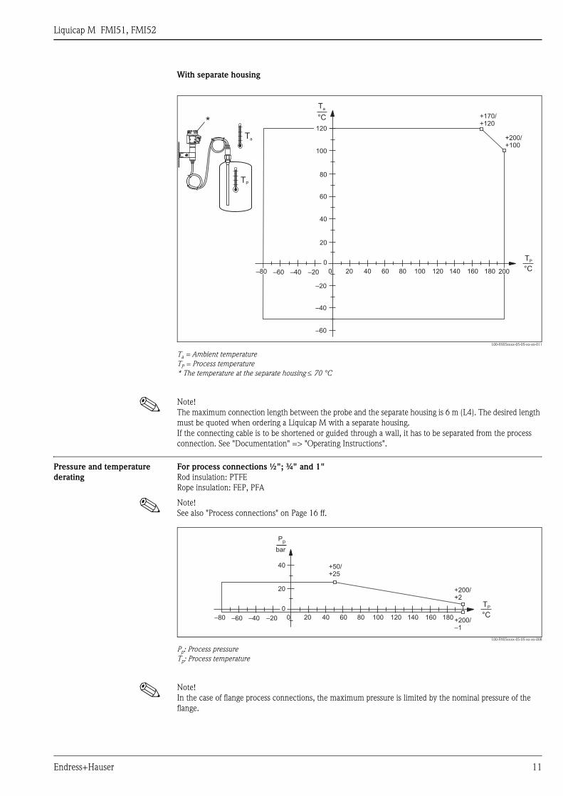
With separate housing
L00-FMI5xxxx-05-05-xx-xx-011
Ta = Ambient temperature
TP = Process temperature
* The temperature at the separate housing ≤ 70 °C
! Note!
The maximum connection length between the probe and the separate housing is 6 m (L4). The desired length
must be quoted when ordering a Liquicap M with a separate housing.
If the connecting cable is to be shortened or guided through a wall, it has to be separated from the process
connection. See "Documentation" => "Operating Instructions".
Pressure and temperature
derating
For process connections ½"; ¾" and 1"
Rod insulation: PTFE
Rope insulation: FEP, PFA
! Note!
See also "Process connections" on Page 16 ff.
L00-FMI5xxxx-05-05-xx-xx-008
Pp: Process pressure
Tp: Process temperature
! Note!
In the case of flange process connections, the maximum pressure is limited by the nominal pressure of the
flange.
Ta
TP
0
0
TP
–40 –20–60 80 120 160 180
80
60
40
20
–80 200
–60
–40
–20
20 40 60 100 140
+200/+100
+170+120
/
°C
Ta
120
100
°C*
bar
Pp
0
0–40 –20–60 80 120 160 180
40
20
–80 +200/–1
20 40 60 100 140
+200/+2
+50/+25
TP
°C
Liquicap M FMI51, FMI52
12 Endress+Hauser
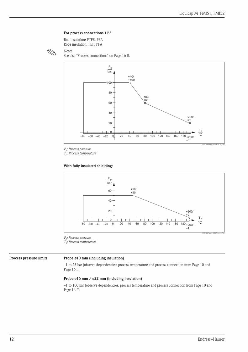
For process connections 1½"
Rod insulation: PTFE, PFA
Rope insulation: FEP, PFA
! Note!
See also "Process connections" on Page 16 ff.
L00-FMI5xxxx-05-05-xx-xx-010
Pp: Process pressure
Tp: Process temperature
With fully insulated shielding:
L00-FMI5xxxx-05-05-xx-xx-012
Pp: Process pressure
Tp: Process temperature
Process pressure limits Probe ø10 mm (including insulation)
–1 to 25 bar (observe dependencies: process temperature and process connection from Page 10 and
Page 16 ff.)
Probe ø16 mm / ø22 mm (including insulation)
–1 to 100 bar (observe dependencies: process temperature and process connection from Page 10 and
Page 16 ff.)
bar
Pp
0
0–40 –20–60 80 120 160 180
60
40
80
20
–80 +200/–1
20 40 60 100 140
+200/+20
+80/+60
+40/+100
TP
°C
100
bar
Pp
0
0–40 –20–60 80 120 160 180
60
40
20
–80 +200/–1
20 40 60 100 140
+200/+2
+50/+50
TP
°C
Liquicap M FMI51, FMI52
Endress+Hauser 13
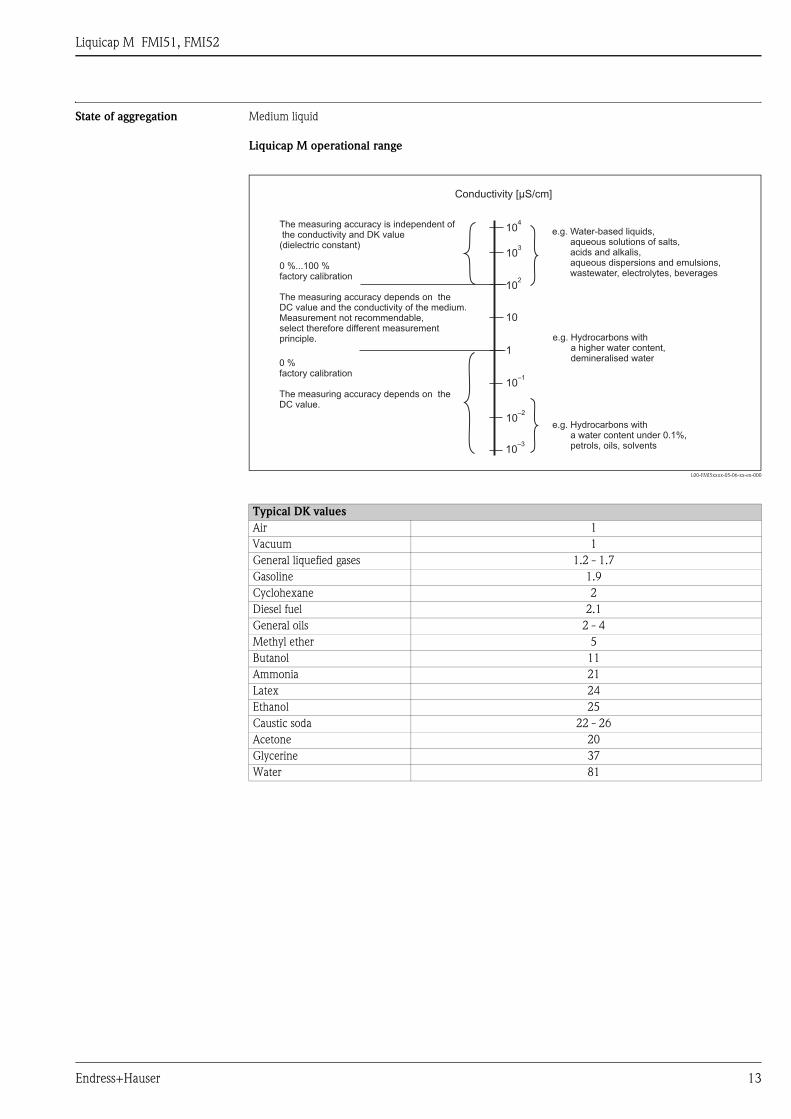
State of aggregation Medium liquid
Liquicap M operational range
L00-FMI5xxxx-05-06-xx-en-000
Typical DK values
Air 1
Vacuum 1
General liquefied gases 1.2 - 1.7
Gasoline 1.9
Cyclohexane 2
Diesel fuel 2.1
General oils 2 - 4
Methyl ether 5
Butanol 11
Ammonia 21
Latex 24
Ethanol 25
Caustic soda 22 - 26
Acetone 20
Glycerine 37
Water 81
10–3
10–2
10–1
1
10
102
103
104
Conductivity [µS/cm]
The measuring accuracy is independent ofthe conductivity and DK value(dielectric constant)
0 %...100 %factory calibration
e.g. Hydrocarbons witha water content under 0.1%,petrols, oils, solvents
e.g. Hydrocarbons witha higher water content,demineralised water
e.g. Water-based liquids,aqueous solutions of salts,acids and alkalis,aqueous dispersions and emulsions,wastewater, electrolytes, beverages
0 %factory calibration
The measuring accuracy depends on theDC value.
The measuring accuracy depends on theDC value and the conductivity of the medium.Measurement not recommendable,select therefore different measurementprinciple.
Liquicap M FMI51, FMI52
14 Endress+Hauser
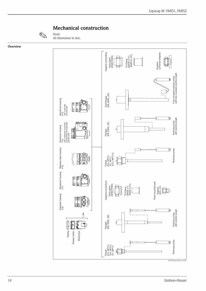
Mechanical construction
! Note!
All dimensions in mm.
Overview
L00-FMI5xxxx-03-05-xx-en-001
Po
lye
ste
rh
ou
sin
gF
16
Alu
min
ium
ho
usin
gF
17
Sta
inle
ss
ste
elh
ou
sin
gF
15
Alu
min
ium
T1
3h
ou
sin
g
with
ase
pa
rate
co
nn
ectio
nco
mpa
rtm
en
ta
nd
ga
s-t
igh
tp
roce
ss
se
al
Alu
min
ium
F1
3h
ou
sin
g
with
ag
as-t
igh
tp
roce
ss
se
al
Ro
d/r
op
ep
rob
eR
od
/ro
pe
pro
be
Ro
d/r
op
ep
rob
ew
ith
ina
ctive
len
gth
Ro
d/r
op
ep
rob
ew
ith
ina
ctive
len
gth
Fu
llyin
su
late
dro
d/r
op
ep
rob
ew
ith
fully
insu
late
din
active
len
gth
Tri-C
lam
p(D
N3
8(1
½")
;D
N4
0-5
1(2
"))
Cla
dfla
ng
es
(EN
,A
NS
I,JIS
)H
ose
gla
nd
(DN
50
PN
40
)
Th
rea
d(G
¾,
NP
T¾
;G
1,
NP
T1
;G
1½
,N
PT
1½
)
Fla
ng
es
(EN
,A
NS
I,JIS
)
Tri-C
lam
p(D
N2
5(1
");
DN
38
(1½
"))
Hyg
ien
e(G
¾,
G1
)
Ho
se
gla
nd
(DN
50
PN
40
)
Th
rea
d(G
½,
NP
T½
;G
¾,
NP
T¾
;G
1,
NP
T1
)
Fla
ng
es
(EN
,A
NS
I,JIS
)
Ele
ctr
on
ics
Dis
pla
y
Dis
pla
yh
old
er
Hyg
ien
e(u
niv
ers
ala
da
pte
r)
Hyg
ien
eco
nn
ectio
ns
Flu
sh
-mo
un
ted
se
al
Hyg
ien
eco
nn
ectio
ns

Liquicap M FMI51, FMI52
Endress+Hauser 15
Housing
! Note!
High cover for housing with display.
Polyester housing F16
L00-FMI5xxxx-06-05-xx-en-001
Stainless steel housing F15
L00-FMI5xxxx-06-05-xx-en-003
Aluminum housing F17
L00-FMI5xxxx-06-05-xx-en-002
Aluminum housing F13
With gas-tight process
seal
L00-FMI5xxxx-06-05-xx-en-000
Aluminum housing T13
With separate connection
compartment and gas-tight
process seal
L00-FMI5xxxx-06-05-xx-en-004
ø85 max. 76
ap
pro
x.
97
ap
pro
x.
11
6
ø76 max. 64
appr
ox.9
5
appr
ox.1
34
ø80 max. 60
max. 65
ap
pro
x.1
05
ap
pro
x.1
34
ø80 max. 60
max. 65
appro
x.118
appro
x.147
max. 65 max. 97
appro
x.135
appro
x.147
Liquicap M FMI51, FMI52
16 Endress+Hauser
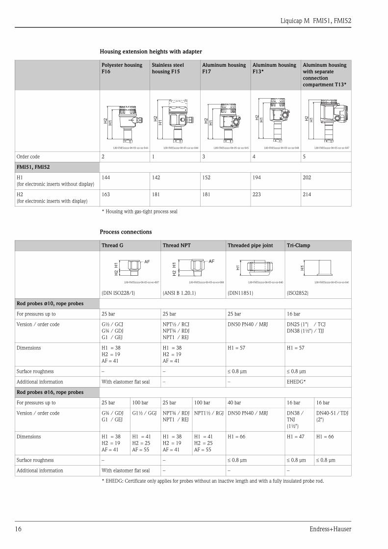
Housing extension heights with adapter
Process connections
Polyester housing
F16
Stainless steel
housing F15
Aluminum housing
F17
Aluminum housing
F13*
Aluminum housing
with separate
connection
compartment T13*
L00-FMI5xxxx-06-05-xx-xx-044 L00-FMI5xxxx-06-05-xx-xx-046 L00-FMI5xxxx-06-05-xx-xx-045 L00-FMI5xxxx-06-05-xx-xx-048 L00-FMI5xxxx-06-05-xx-xx-047
Order code 2 1 3 4 5
FMI51, FMI52
H1
(for electronic inserts without display)
144 142 152 194 202
H2
(for electronic inserts with display)
163 181 181 223 214
* Housing with gas-tight process seal
H1H2
H1H
2
H1H2 H1H
2
H1H2
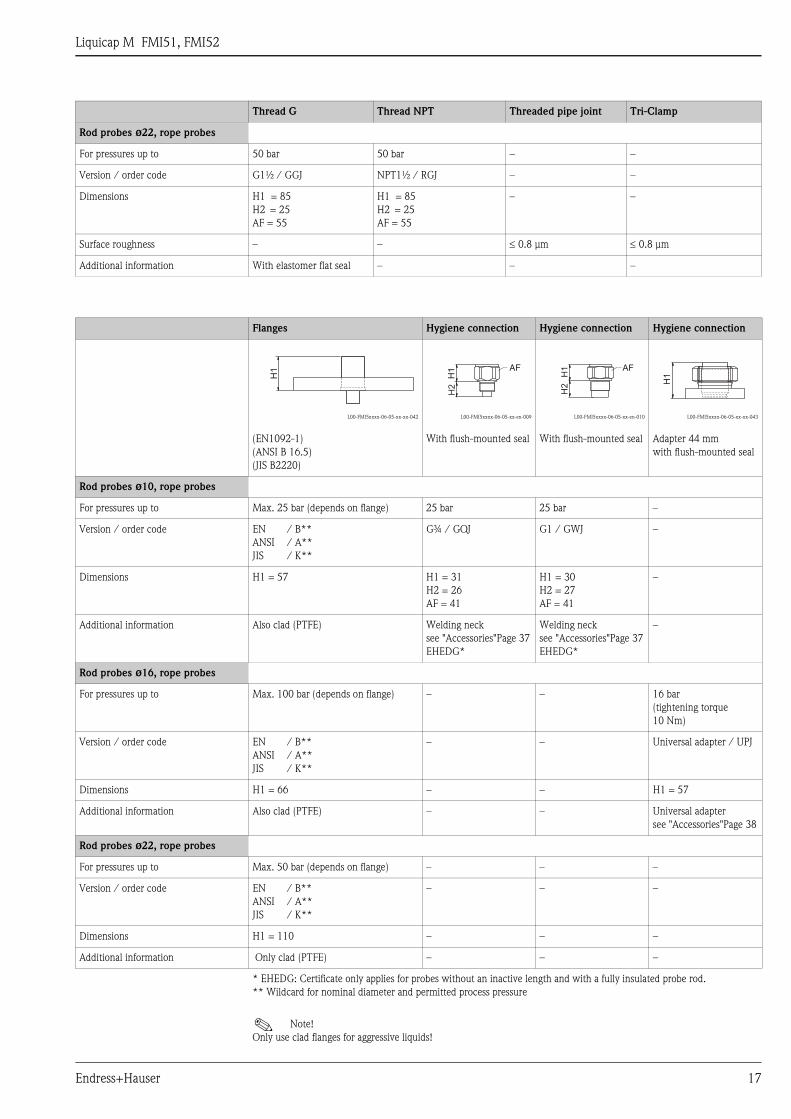
Thread G Thread NPT Threaded pipe joint Tri-Clamp
L00-FMI5xxxx-06-05-xx-en-007
(DIN ISO228/I)
L00-FMI5xxxx-06-05-xx-en-008
(ANSI B 1.20.1)
L00-FMI5xxxx-06-05-xx-xx-040
(DIN11851)
L00-FMI5xxxx-06-05-xx-xx-041
(ISO2852)
Rod probes ø10, rope probes
For pressures up to 25 bar 25 bar 25 bar 16 bar
Version / order code G½ / GCJ
G¾ / GDJ
G1 / GEJ
NPT½ / RCJ
NPT¾ / RDJ
NPT1 / REJ
DN50 PN40 / MRJ DN25 (1") / TCJ
DN38 (1½") / TJJ
Dimensions H1 = 38
H2 = 19
AF = 41
H1 = 38
H2 = 19
AF = 41
H1 = 57 H1 = 57
Surface roughness – – ≤ 0.8 μm ≤ 0.8 μm
Additional information With elastomer flat seal – – EHEDG*
Rod probes ø16, rope probes
For pressures up to 25 bar 100 bar 25 bar 100 bar 40 bar 16 bar 16 bar
Version / order code G¾ / GDJ
G1 / GEJ
G1½ / GGJ NPT¾ / RDJ
NPT1 / REJ
NPT1½ / RGJ DN50 PN40 / MRJ DN38 /
TNJ
(1½")
DN40-51 / TDJ
(2")
Dimensions H1 = 38
H2 = 19
AF = 41
H1 = 41
H2 = 25
AF = 55
H1 = 38
H2 = 19
AF = 41
H1 = 41
H2 = 25
AF = 55
H1 = 66 H1 = 47 H1 = 66
Surface roughness – – ≤ 0.8 μm ≤ 0.8 μm ≤ 0.8 μm
Additional information With elastomer flat seal – – –
* EHEDG: Certificate only applies for probes without an inactive length and with a fully insulated probe rod.
H1
H2
AF
H1
H2
AF
H1
H1
Liquicap M FMI51, FMI52
Endress+Hauser 17
Rod probes ø22, rope probes
For pressures up to 50 bar 50 bar – –
Version / order code G1½ / GGJ NPT1½ / RGJ – –
Dimensions H1 = 85
H2 = 25
AF = 55
H1 = 85
H2 = 25
AF = 55
– –
Surface roughness – – ≤ 0.8 μm ≤ 0.8 μm
Additional information With elastomer flat seal – – –
Thread G Thread NPT Threaded pipe joint Tri-Clamp
Flanges Hygiene connection Hygiene connection Hygiene connection
L00-FMI5xxxx-06-05-xx-xx-042
(EN1092-1)
(ANSI B 16.5)
(JIS B2220)
L00-FMI5xxxx-06-05-xx-en-009
With flush-mounted seal
L00-FMI5xxxx-06-05-xx-en-010
With flush-mounted seal
L00-FMI5xxxx-06-05-xx-xx-043
Adapter 44 mm
with flush-mounted seal
Rod probes ø10, rope probes
For pressures up to Max. 25 bar (depends on flange) 25 bar 25 bar –
Version / order code EN
ANSI
JIS
/ B**
/ A**
/ K**
G¾ / GQJ G1 / GWJ –
Dimensions H1 = 57 H1 = 31
H2 = 26
AF = 41
H1 = 30
H2 = 27
AF = 41
–
Additional information Also clad (PTFE) Welding neck
see "Accessories"Page 37
EHEDG*
Welding neck
see "Accessories"Page 37
EHEDG*
–
Rod probes ø16, rope probes
For pressures up to Max. 100 bar (depends on flange) – – 16 bar
(tightening torque
10 Nm)
Version / order code EN
ANSI
JIS
/ B**
/ A**
/ K**
– – Universal adapter / UPJ
Dimensions H1 = 66 – – H1 = 57
Additional information Also clad (PTFE) – – Universal adapter
see "Accessories"Page 38
Rod probes ø22, rope probes
For pressures up to Max. 50 bar (depends on flange) – – –
Version / order code EN
ANSI
JIS
/ B**
/ A**
/ K**
– – –
Dimensions H1 = 110 – – –
Additional information Only clad (PTFE) – – –
* EHEDG: Certificate only applies for probes without an inactive length and with a fully insulated probe rod.
** Wildcard for nominal diameter and permitted process pressure
! Note!
Only use clad flanges for aggressive liquids!
H1
H1
H2
AF
H1
H2
AF
H1
Liquicap M FMI51, FMI52
18 Endress+Hauser
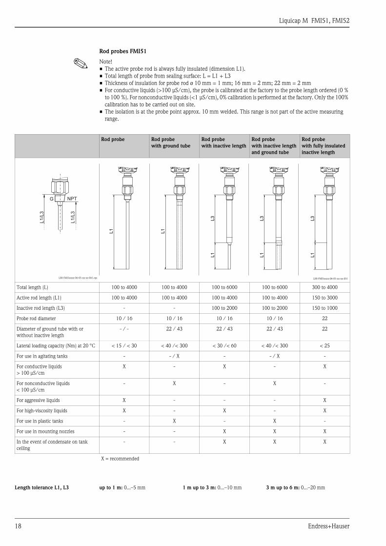
Rod probes FMI51
! Note!
• The active probe rod is always fully insulated (dimension L1).
• Total length of probe from sealing surface: L = L1 + L3
• Thickness of insulation for probe rod ø 10 mm = 1 mm; 16 mm = 2 mm; 22 mm = 2 mm
• For conductive liquids (>100 μS/cm), the probe is calibrated at the factory to the probe length ordered (0 %
to 100 %). For nonconductive liquids (<1 μS/cm), 0% calibration is performed at the factory. Only the 100%
calibration has to be carried out on site.
• The isolation is at the probe point approx. 10 mm welded. This range is not part of the active measuring
range.
Rod probe Rod probe
with ground tube
Rod probe
with inactive length
Rod probe
with inactive length
and ground tube
Rod probe
with fully insulated
inactive length
L00-FMI5xxxx-06-05-xx-xx-061.eps L00-FMI5xxxx-06-05-xx-xx-051
Total length (L) 100 to 4000 100 to 4000 100 to 6000 100 to 6000 300 to 4000
Active rod length (L1) 100 to 4000 100 to 4000 100 to 4000 100 to 4000 150 to 3000
Inactive rod length (L3) - - 100 to 2000 100 to 2000 150 to 1000
Probe rod diameter 10 / 16 10 / 16 10 / 16 10 / 16 22
Diameter of ground tube with or
without inactive length
- / - 22 / 43 22 / 43 22 / 43 22
Lateral loading capacity (Nm) at 20 °C < 15 / < 30 < 40 /< 300 < 30 /< 60 < 40 /< 300 < 25
For use in agitating tanks - - / X - - / X -
For conductive liquids
> 100 μS/cm
X - X - X
For nonconductive liquids
< 100 μS/cm
- X - X -
For aggressive liquids X - - - X
For high-viscosity liquids X - X - X
For use in plastic tanks - X - X -
For use in mounting nozzles - - X X X
In the event of condensate on tank
ceiling
- - X X X
X = recommended
L1
/L3
L1
/L3
NPTG
L1
L1
L3
L3
L1
L1
L3
L3
L1
L1
L1
L1
L3
L3
L1
L1
Length tolerance L1, L3 up to 1 m: 0...–5 mm 1 m up to 3 m: 0...–10 mm 3 m up to 6 m: 0...–20 mm
Liquicap M FMI51, FMI52
Endress+Hauser 19
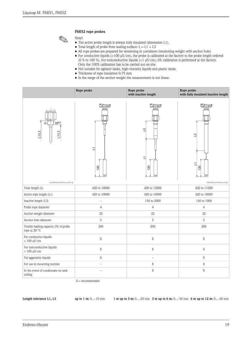
FMI52 rope probes
! Note!
• The active probe length is always fully insulated (dimension L1).
• Total length of probe from sealing surface: L = L1 + L3
• All rope probes are prepared for tensioning in containers (tensioning weight with anchor hole)
• For conductive liquids (>100 μS/cm), the probe is calibrated at the factory to the probe length ordered
(0 % to 100 %). For nonconductive liquids (<1 μS/cm), 0% calibration is performed at the factory.
Only the 100% calibration has to be carried out on site.
• Not suitable for agitator tanks, high-viscosity liquids and plastic tanks.
• Thickness of rope insulation 0.75 mm
• In the range of the anchor weight the measurement is not linear.
Rope probe Rope probe
with inactive length
Rope probe
with fully insulated inactive length
L00-FMI5xxxx-06-05-xx-xx-061.eps L00-FMI5xxxx-06-05-xx-xx-036
Total length (L) 420 to 10000 420 to 12000 420 to 11000
Active rope length (L1) 420 to 10000 420 to 10000 420 to 10000
Inactive length (L3) - 150 to 2000 150 to 1000
Probe rope diameter 4 4 4
Anchor weight diameter 22 22 22
Anchor hole diameter 5 5 5
Tensile loading capacity (N) of probe
rope at 20 °C
200 200 200
For conductive liquids
> 100 μS/cmX X X
For nonconductive liquids
< 100 μS/cmX X X
For aggressive liquids X - X
For use in mounting nozzles - X X
In the event of condensate on tank
ceiling
- X X
X = recommended
L1
/L3
L1
/L3
NPTG
120
120
L1
L1
120
120
L1
L1
120
120
L1
L1
L3
L3
L3
L3
Length tolerance L1, L3 up to 1 m: 0...–10 mm 1 m up to 3 m: 0...–20 mm 3 m up to 6 m: 0...–30 mm 6 m up to 12 m: 0...–40 mm
Liquicap M FMI51, FMI52
20 Endress+Hauser
Technical data (probe) Capacitance values of probe
• Basic capacitance: approx. 18 pF
Additional capacitance
• Mount the probe with a minimum distance of 50 mm from a conductive container wall:
Probe rod: approx. 1.3 pF/100 mm in air
Probe rope: approx. 1.0 pF/100 mm in air
• Fully insulated probe rod in water:
Approx. 38 pF/100 mm (16 mm rod)
Approx. 45 pF/100 mm (10 mm rod)
Approx. 50 pF/100 mm (22 mm rod)
• Insulated probe rope in water: approx. 19 pF/100 mm
• Rod probe with ground tube:
– Insulated probe rod: in air approx. 6.4 pF/100 mm
– Insulated probe rod: in water approx. 38 pF/100 mm (16 mm rod)
– Insulated probe rod: in water approx. 45 pF/100 mm (10 mm rod)
Probe lengths for continuous measurement in conductive liquids
• With FEI57C, FEI50H
– Rod probe (range 0 to 2000 pF for ≤ 4000 mm)
– Rope probe < 6 m (range 0 to 2000 pF)
– Rope probe > 6 m (range 0 to 4000 pF)
Weight • With F15, F16, F17 or F13 housing approx. 4.0 kg
• + Flange weight
• + Probe rod 0.5 kg/m (with ø10 mm probe rod) or
+ Probe rod 1.1 kg/m (with ø16 mm probe rod) or
+ Probe rope 0.04 kg/m (with rope probes)
• With T13 housing approx. 4.5 kg
• + Flange weight
• + Probe rod 0.5 kg/m (with ø10 mm probe rod) or
+ Probe rod 1.1 kg/m (with ø16 mm probe rod) or
+ Probe rope 0.04 kg/m (with rope probes)
Material Housing
• Aluminum housing F17, F13, T13: GD-Al Si 10 Mg, DIN 1725, with plastic coating (blue/gray)
• Polyester housing F16: PBT-FR fiberglass reinforced polyester (blue/gray)
• Stainless steel housing F15: corrosion-resistant steel 316L (14435), uninsulated
Housing cover and seals
• Housing cover and seals:
– Aluminum housing F17, F13, T13: EN-AC-AlSi10Mg, plastic-coated
cover seal: EPDM
– Polyester housing F16: cover made of PBT-FR or with cover with sight glass made of PA12
cover seal: EPDM
– Stainless steel housing F15: AISI 316L
cover seal: silicone
Process connection seal
• Sealing ring for process connection G½, G¾, G1, G1½ :
Elastomer fiber, asbestos-free, resistant to oils, solvents, steam, weak acids and alkalis;
To 300 °C and to 100 bar
Probe material
• Probe rod, ground tube, process connection, inactive length, tensioning weight for rope probe: 1.4435
(316L)
• Probe rope: 1.4401 (AISI 316)
• Probe insulation: PFA or PTFE (in conformity with FDA)
• Rope insulation: PFA or FEP (in conformity with FDA)
Liquicap M FMI51, FMI52
Endress+Hauser 21
Input
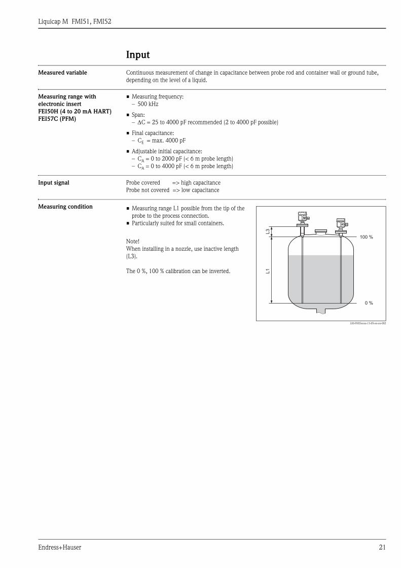
Measured variable Continuous measurement of change in capacitance between probe rod and container wall or ground tube,
depending on the level of a liquid.
Measuring range with
electronic insert
FEI50H (4 to 20 mA HART)
FEI57C (PFM)
• Measuring frequency:
– 500 kHz
• Span:
– ΔC = 25 to 4000 pF recommended (2 to 4000 pF possible)
• Final capacitance:
– CE = max. 4000 pF
• Adjustable initial capacitance:
– CA = 0 to 2000 pF (< 6 m probe length)
– CA = 0 to 4000 pF (< 6 m probe length)
Input signal Probe covered => high capacitance
Probe not covered => low capacitance
Measuring condition • Measuring range L1 possible from the tip of the
probe to the process connection.
• Particularly suited for small containers.
Note!
When installing in a nozzle, use inactive length
(L3).
The 0 %, 100 % calibration can be inverted.
L00-FMI5xxxx-15-05-xx-xx-002
100 %
0 %
L3
L1
Liquicap M FMI51, FMI52
22 Endress+Hauser
Output
Output signal FEI50H (4 to 20mA/HART Version 5.0)
• 3.8 to 20.5 mA with HART protocol
FEI57C (PFM)
• The transmitter superimposes current pulses (PFM signal 60 to 2800 Hz) with a pulse width of approx. 100
μs and a current strength of approx. 8 mA on the supply current (approx. 8 mA).
Signal on alarm FEI50H
Fault diagnosis can be called up as follows:
• Via the local display:
– Red LED
• Via the local display showing:
– Error symbol
– Plain text display
• Via the current output: 22 mA
• Via the digital interface (HART status error message)
FEI57C
Fault diagnosis can be called up as follows:
• Via the local display:
– Red LED
• Via the local display at the switching unit: silometer (FMX570, FMC671/672), Prolevel (FMC661/662)
Linearization FEI50H
The Liquicap M linearization function enables conversion of the measured value into any desired length
or volume units. Linearization tables for volume calculation of horizontal cylindrical tanks and spherical tanks
are pre-programmed. Any other tables with up to 32 value pairs can be input manually or semi-automatically.
FEI57C
With FEI57C, linearization takes place in the switching units.
Liquicap M FMI51, FMI52
Endress+Hauser 23
Power supply
Electrical connection Connection compartment
Five housings are available:
Terminal assignment
Standard EEx ia EEx d Gas-tight process
seal
Plastic housing F16 X X - -
Stainless steel housing F15 X X - -
Aluminum housing F17 X X - -
Aluminum housing F13 X X - X
Aluminum housing T13
(with separate connection compartment)
X X X X
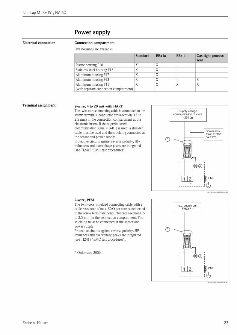
2-wire, 4 to 20 mA with HART
The twin-core connecting cable is connected to the
screw terminals (conductor cross-section 0.5 to
2.5 mm) in the connection compartment at the
electronic insert. If the superimposed
communication signal (HART) is used, a shielded
cable must be used and the shielding connected at
the sensor and power supply.
Protective circuits against reverse polarity, HF-
influences and overvoltage peaks are integrated
(see TI241F "EMC test procedures").
L00-FMI5xxxx-04-00-00-en-002
2-wire, PFM
The twin-core, shielded connecting cable with a
cable resistance of max. 50 Ω per core is connected
to the screw terminals (conductor cross-section 0.5
to 2.5 mm) in the connection compartment. The
shielding must be connected at the sensor and
power supply.
Protective circuits against reverse polarity, HF-
influences and overvoltage peaks are integrated
(see TI241F "EMC test procedures").
* Order stop 2006.
L00-FMI5xxxx-04-00-00-en-003
1 2– +
CommuboxFXA191/195DXR375
PML
Supply voltage,communication resistor
(250 )Ω
1 2– +
eFMC671*
.g. supply unit
PML
Liquicap M FMI51, FMI52
24 Endress+Hauser
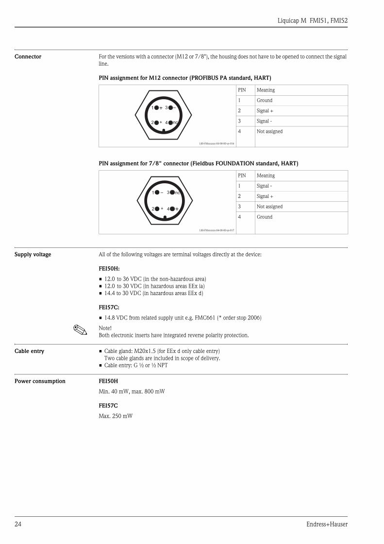
Connector For the versions with a connector (M12 or 7/8"), the housing does not have to be opened to connect the signal
line.
PIN assignment for M12 connector (PROFIBUS PA standard, HART)
PIN assignment for 7/8" connector (Fieldbus FOUNDATION standard, HART)
Supply voltage All of the following voltages are terminal voltages directly at the device:
FEI50H:
• 12.0 to 36 VDC (in the non-hazardous area)
• 12.0 to 30 VDC (in hazardous areas EEx ia)
• 14.4 to 30 VDC (in hazardous areas EEx d)
FEI57C:
• 14.8 VDC from related supply unit e.g. FMC661 (* order stop 2006)
! Note!
Both electronic inserts have integrated reverse polarity protection.
Cable entry • Cable gland: M20x1.5 (for EEx d only cable entry)
Two cable glands are included in scope of delivery.
• Cable entry: G ½ or ½ NPT
Power consumption FEI50H
Min. 40 mW, max. 800 mW
FEI57C
Max. 250 mW
L00-FMxxxxxx-04-00-00-yy-016
PIN Meaning
1 Ground
2 Signal +
3 Signal -
4 Not assigned
L00-FMxxxxxx-04-00-00-yy-017
PIN Meaning
1 Signal -
2 Signal +
3 Not assigned
4 Ground
2
1 3
4+
–
nc
2
1 3
4+
– nc
Liquicap M FMI51, FMI52
Endress+Hauser 25
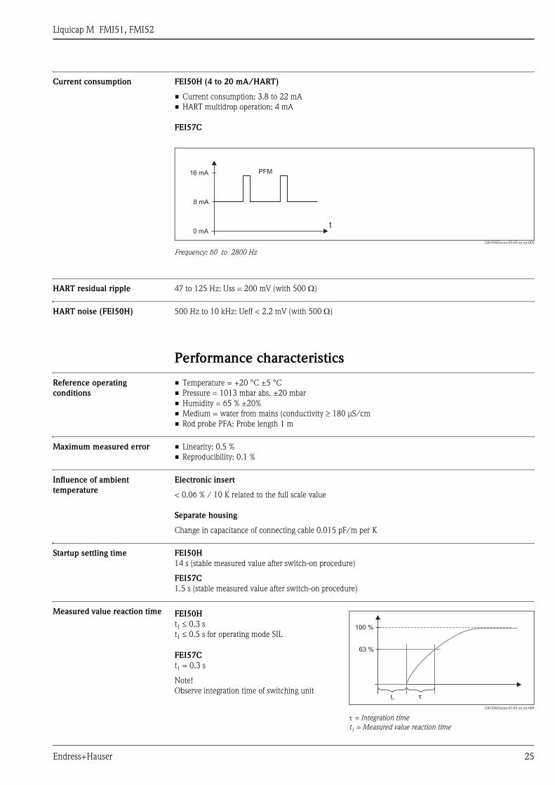
Current consumption FEI50H (4 to 20 mA/HART)
• Current consumption: 3.8 to 22 mA
• HART multidrop operation: 4 mA
FEI57C
L00-FMI5xxxx-05-05-xx-xx-005
Frequency: 60 to 2800 Hz
HART residual ripple 47 to 125 Hz: Uss = 200 mV (with 500 Ω)
HART noise (FEI50H) 500 Hz to 10 kHz: Ueff < 2.2 mV (with 500 Ω)
Performance characteristics
Reference operating
conditions
• Temperature = +20 °C ±5 °C
• Pressure = 1013 mbar abs. ±20 mbar
• Humidity = 65 % ±20%
• Medium = water from mains (conductivity ≥ 180 μS/cm
• Rod probe PFA: Probe length 1 m
Maximum measured error • Linearity: 0.5 %
• Reproducibility: 0.1 %
Influence of ambient
temperature
Electronic insert
< 0.06 % / 10 K related to the full scale value
Separate housing
Change in capacitance of connecting cable 0.015 pF/m per K
Startup settling time FEI50H
14 s (stable measured value after switch-on procedure)
FEI57C
1.5 s (stable measured value after switch-on procedure)
Measured value reaction time
0 mA
8 mA
16 mA PFM
t
FEI50H
t1 ≤ 0.3 s
t1 ≤ 0.5 s for operating mode SIL
L00-FMI5xxxx-05-05-xx-xx-009
τ = Integration time
t1 = Measured value reaction time
FEI57C
t1 = 0.3 s
Note!
Observe integration time of switching unit
63 %
100 %
t1τ
Liquicap M FMI51, FMI52
26 Endress+Hauser
Integration time FEI50H
τ =1 s (factory setting) 0 to 60 s can be set.
The integration time affects the speed at which the display and the current output react to changes in the level.
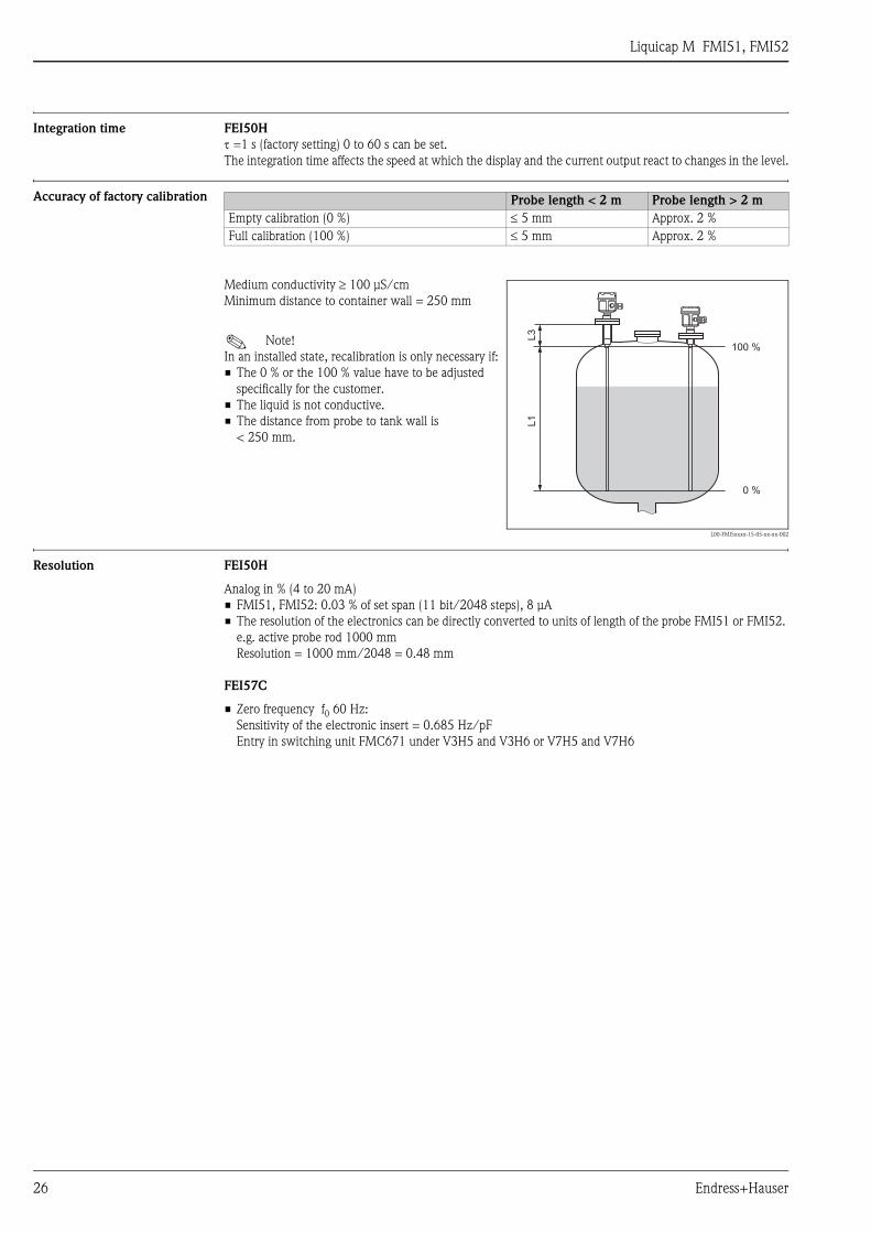
Accuracy of factory calibration
Resolution FEI50H
Analog in % (4 to 20 mA)
• FMI51, FMI52: 0.03 % of set span (11 bit/2048 steps), 8 μA
• The resolution of the electronics can be directly converted to units of length of the probe FMI51 or FMI52.
e.g. active probe rod 1000 mm
Resolution = 1000 mm/2048 = 0.48 mm
FEI57C
• Zero frequency f0 60 Hz:
Sensitivity of the electronic insert = 0.685 Hz/pF
Entry in switching unit FMC671 under V3H5 and V3H6 or V7H5 and V7H6
Probe length < 2 m Probe length > 2 m
Empty calibration (0 %) ≤ 5 mm Approx. 2 %
Full calibration (100 %) ≤ 5 mm Approx. 2 %
Medium conductivity ≥ 100 μS/cm
Minimum distance to container wall = 250 mm
! Note!
In an installed state, recalibration is only necessary if:
• The 0 % or the 100 % value have to be adjusted
specifically for the customer.
• The liquid is not conductive.
• The distance from probe to tank wall is
< 250 mm.
L00-FMI5xxxx-15-05-xx-xx-002
100 %
0 %
L3
L1
Liquicap M FMI51, FMI52
Endress+Hauser 27
Human interface
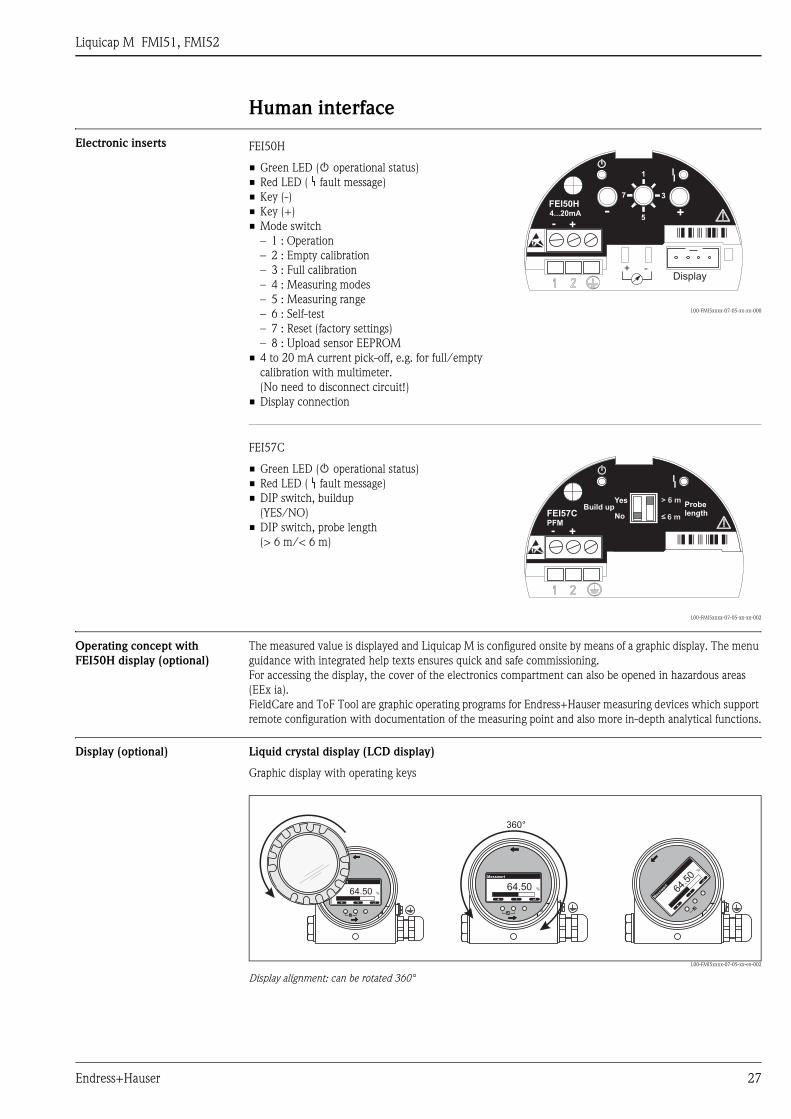
Electronic inserts
Operating concept with
FEI50H display (optional)
The measured value is displayed and Liquicap M is configured onsite by means of a graphic display. The menu
guidance with integrated help texts ensures quick and safe commissioning.
For accessing the display, the cover of the electronics compartment can also be opened in hazardous areas
(EEx ia).
FieldCare and ToF Tool are graphic operating programs for Endress+Hauser measuring devices which support
remote configuration with documentation of the measuring point and also more in-depth analytical functions.
Display (optional) Liquid crystal display (LCD display)
Graphic display with operating keys
L00-FMI5xxxx-07-05-xx-en-002
Display alignment: can be rotated 360°
FEI50H
• Green LED ( operational status)
• Red LED ( fault message)
• Key (-)
• Key (+)
• Mode switch
– 1 : Operation
– 2 : Empty calibration
– 3 : Full calibration
– 4 : Measuring modes
– 5 : Measuring range
– 6 : Self-test
– 7 : Reset (factory settings)
– 8 : Upload sensor EEPROM
• 4 to 20 mA current pick-off, e.g. for full/empty
calibration with multimeter.
(No need to disconnect circuit!)
• Display connection
L00-FMI5xxxx-07-05-xx-xx-000
FEI57C
• Green LED ( operational status)
• Red LED ( fault message)
• DIP switch, buildup
(YES/NO)
• DIP switch, probe length
(> 6 m/< 6 m)
L00-FMI5xxxx-07-05-xx-xx-002
- +
FEI50H4...20mA - +
+ -Display
1
7 3
5
- +
FEI57CPFM
> 6 m> 6 m
6 m6 m
Yes
NoBuild up Probe
length
360°
64.50 %
+ ↵
Messwert
64.50 %
+ ↵
Messwert
64.50 %
+ ↵
MesswertMes
64.5
0%
+
↵
Mes
swer
t
Liquicap M FMI51, FMI52
28 Endress+Hauser
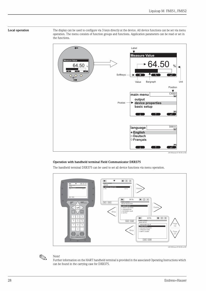
Local operation The display can be used to configure via 3 keys directly at the device. All device functions can be set via menu
operation. The menu consists of function groups and functions. Application parameters can be read or set in
the functions.
L00-FMIxxxxx-07-00-00-en-002
Operation with handheld terminal Field Communicator DXR375
The handheld terminal DXR375 can be used to set all device functions via menu operation.
L00-FMI5xxxx-07-00-00-xx-007
! Note!
Further information on the HART handheld terminal is provided in the associated Operating Instructions which
can be found in the carrying case for DXR375.
Label
Position
Bargraph
Softkeys
64.50 %
+ ↵
Value Unit
Picklist
↵↑↑
main menu
outputdevice propertiesbasic setup
↵
D0011
EnglishDeutschFran aisç
↑↑
language
64.50 %
+ ↵
Measure Value
CX001
Measure Value
1# % &
Copy
G H I
P Q R S
, ( ) ‘
A B C
Paste
PageOn
PageUp
DeleteBksp
Insert
J K L
T U V
_ < >
D E F
Hot Key
+ Hot Key
M N O
W X Y Z
+ * /
4
7
.
2
5
8
0
375FIELD COMMUNICATOR
3
6
9
-
FMR231: LIC0001ONLINE
1 GROUP SELECT2 PV 8.7 m
HELP SAVE
dsdmdmdf das.asdas faasas la.
PageOn
PageUp
Bksp
Delete
Delete
FMI51: LIC0001ONLINE
1 GROUP SELECTION2 PV 8.7 m
HELP SAVE
dsdmdmdf das.asdas faasas la.
GROUP SELECTION
HOMESAVE
dsdmdmdf das.asdas faasas la.H
HOMESAVE
dsdmdmdf das.asdas faasas la.H
Bksp
1 BASIC SETUP2 SAFETY SETTINGS
BASIC SETUP
1 MEASURED VALUE
4 PROCESS COND.
5 EMPTY CALIBR.
3 MEDIUM PROPERTY
4 EXTENDED CALIB.
5 OUTPUT
3 LINEARISATION
2 TANK SHAPE
FMI51: LIC0001
FMI51: LIC0001
Liquicap M FMI51, FMI52
Endress+Hauser 29
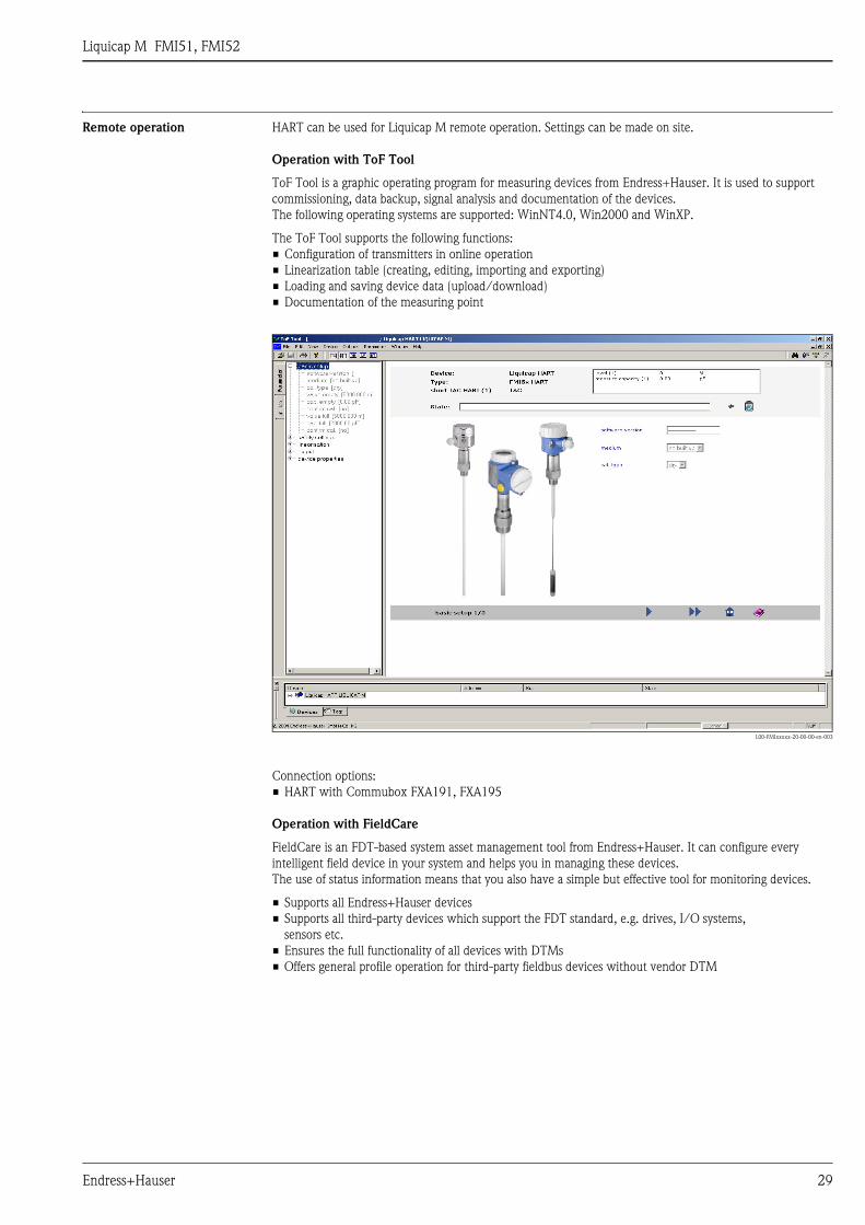
Remote operation HART can be used for Liquicap M remote operation. Settings can be made on site.
Operation with ToF Tool
ToF Tool is a graphic operating program for measuring devices from Endress+Hauser. It is used to support
commissioning, data backup, signal analysis and documentation of the devices.
The following operating systems are supported: WinNT4.0, Win2000 and WinXP.
The ToF Tool supports the following functions:
• Configuration of transmitters in online operation
• Linearization table (creating, editing, importing and exporting)
• Loading and saving device data (upload/download)
• Documentation of the measuring point
L00-FMIxxxxx-20-00-00-en-003
Connection options:
• HART with Commubox FXA191, FXA195
Operation with FieldCare
FieldCare is an FDT-based system asset management tool from Endress+Hauser. It can configure every
intelligent field device in your system and helps you in managing these devices.
The use of status information means that you also have a simple but effective tool for monitoring devices.
• Supports all Endress+Hauser devices
• Supports all third-party devices which support the FDT standard, e.g. drives, I/O systems,
sensors etc.
• Ensures the full functionality of all devices with DTMs
• Offers general profile operation for third-party fieldbus devices without vendor DTM

Liquicap M FMI51, FMI52
30 Endress+Hauser
Certificates and approvals
CE mark The devices are designed to meet state-of-the-art safety requirements, have been tested and left the factory in
a condition in which they are safe to operate. The devices comply with the applicable standards and regulations
that are listed in the EC Declaration of Conformity and thus meet the legal requirements of the EC Directives.
Endress+Hauser confirms the conformity of the device by affixing to it the CE mark.
Ex approval See "Ordering information" from Page 30
Other standards and
guidelines
EN 60529
Degrees of protection by housing (IP code)
EN 61010
Protection measures for electrical equipment for measurement, control, regulation and laboratory procedures
EN 61326
Interference emission (Class B equipment), interference immunity (Annex A - Industrial).
NAMUR
Association for Standards for Control and Regulation in the Chemical Industry
Ordering information
! Note!
In this list, versions which are mutually exclusive are not marked.
Liquicap M FMI51 10 Approval:
A Non-hazardous area
B Non-hazardous area, WHG (German Water Resources Act)
C ATEX II 1/2 GD EEx ia IIC T6
D ATEX II 1/2 GD EEx ia IIC T6, WHG
E ATEX II 1/2 GD EEx ia IIB T6
F ATEX II 1/2 GD EEx ia IIB T6, WHG
H ATEX II 1/2 GD EEx ia IIC T6,
XA, observe safety instructions (electrostatic charge)!
J ATEX II 1/2 GD EEx ia IIC T6, WHG
XA, observe safety instructions (electrostatic charge)!
K ATEX II 1/2 G EEx ia IIC T6, WHG
XA, observe safety instructions (electrostatic charge)!
L ATEX II 1/2 G EEx d (ia) IIC T6, WHG
XA, observe safety instructions (electrostatic charge)!
M ATEX II 3 GD EEx nA II T6, WHG
N CSA General Purpose, CSA C US
P CSA/FM IS Cl. I, II, III Div. 1+2 Gr. A-G
R CSA/FM XP Cl. I, II, III Div. 1+2 Gr. A-G
S TIIS Ex ia IIC T3
T TIIS Ex d IIC T3
Y Special version, to be specified
1 NEPSI Ex ia IIC T6
2 NEPSI Ex d(ia) IIC T6
20 Inactive Length L3:
Price per 100 mm/1 inch
L3: 100 to 2000 mm/4 to 80 inch for 316L
L3: 150 to 1000 mm/6 to 40 inch for PTFE fully insulated
Protection against condensate + bypassing container nozzles
1 Not selected
2 ..... mm, 316L
3 ..... mm, 316L + fully insulated PTFE
5 ..... inch, 316L
6 ..... inch, 316L + fully insulated PTFE
9 Special version, to be specified

Liquicap M FMI51, FMI52
Endress+Hauser 31
30 Active Probe Length L1; Insulation:
Price per 100 mm/1 inch
L1: 100 to 4000 mm/4 to 160 inch for ø10 mm, ø16 mm
L1: 150 to 3000 mm/6 to 120 inch for ø22 mm (fully insulated)
A ..... mm, 10 mm rod, 316L; PTFE
B ..... mm, 16 mm rod, 316L; PTFE
C ..... mm, 22 mm rod, 316L; PTFE
D ..... mm, 16 mm rod, 316L; PFA
E ..... mm, 10 mm rod, 316L; PTFE + ground tube
F ..... mm, 16 mm rod, 316L; PTFE + ground tube
G ..... mm, 16 mm rod, 316L; PFA + ground tube
H ..... inch, 0.4 inch rod, 316L; PTFE
K ..... inch, 0.6 inch rod, 316L; PTFE
M ..... inch, 0.9 inch rod, 316L; PTFE
N ..... inch, 0.6 inch rod, 316L; PFA
P ..... inch, 0.4 inch rod, 316L; PTFE + ground tube
R ..... inch, 0.6 inch rod, 316L; PTFE + ground tube
S ..... inch, 0.6 inch rod, 316L; PFA + ground tube
Y Special version, to be specified
50 Process Connection:
Threaded connection
GCJ G ½, 316L, 25 bar Thread ISO228
GDJ G ¾, 316L, 25 bar Thread ISO228
GEJ G 1, 316L, 25 bar Thread ISO228
GGJ G 1½, 316L, 100 bar Thread ISO228
RCJ NPT ½, 316L, 25 bar Thread ANSI
RDJ NPT ¾, 316L, 25 bar Thread ANSI
REJ NPT 1, 316L, 25 bar Thread ANSI
RGJ NPT 1½, 316L, 100 bar Thread ANSI
Hygiene connection
GQJ G ¾ , 316L, 25 bar, EHEDG Thread ISO228
Accessories installation, welding neck
GWJ G 1, 316L, 25 bar, EHEDG Thread ISO228
Accessories installation, welding neck
MRJ DN50 PN40, 316L DIN11851
UPJ Universal adapter 44 mm 316L, 16 bar
Tri-Clamp connection
TCJ DN25 (1"), 316L, EHEDG Tri-Clamp ISO2852
TJJ DN38 (1½"), 316L, EHEDG Tri-Clamp ISO2852
TDJ DN40-51 (2"), 316L, Tri-Clamp ISO2852
TNJ DN38 (1½"), 316L, 3A Tri-Clamp ISO2852
Tri-Clamp removable
EN flanges
B0J DN25 PN25/40 A, 316L Flange EN1092-1 (DIN2527 B)
B1J DN32 PN25/40 A, 316L Flange EN1092-1 (DIN2527 B)
B2J DN40 PN25/40 A, 316L Flange EN1092-1 (DIN2527 B)
B3J DN50 PN25/40 A, 316L Flange EN1092-1 (DIN2527 B)
CRJ DN50 PN25/40 B1, 316L Flange EN1092-1 (DIN2527 C)
DRJ DN50 PN40 C, 316L Flange EN1092-1 (DIN2512 F)
ERJ DN50 PN40 D, 316L Flange EN1092-1 (DIN2512 N)
BSJ DN80 PN10/16 A, 316L Flange EN1092-1 (DIN2527 B)
CGJ DN80 PN10/16 B1, 316L Flange EN1092-1 (DIN2527 C)
DGJ DN80 PN16 C, 316L Flange EN1092-1 (DIN2512 F)
EGJ DN80 PN16 D, 316L Flange EN1092-1 (DIN2512 N)
BTJ DN100 PN10/16 A, 316L Flange EN1092-1 (DIN2527 B)
CHJ DN100 PN10/16 B1, 316L Flange EN1092-1 (DIN2527 C)
PTFE clad
B0K DN25 PN25/40, PTFE >316L Flange EN1092-1 (DIN2527)
B1K DN32 PN25/40, PTFE >316L Flange EN1092-1 (DIN2527)
B2K DN40 PN25/40, PTFE >316L Flange EN1092-1 (DIN2527)
B3K DN50 PN25/40, PTFE >316L Flange EN1092-1 (DIN2527)
BSK DN80 PN10/16, PTFE >316L Flange EN1092-1 (DIN2527)
BTK DN100 PN10/16, PTFE >316L Flange EN1092-1 (DIN2527)
Liquicap M FMI51, FMI52
32 Endress+Hauser
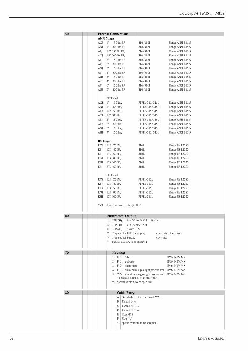
ANSI flanges
ACJ 1" 150 lbs RF, 316/316L Flange ANSI B16.5
ANJ 1" 300 lbs RF, 316/316L Flange ANSI B16.5
AEJ 1½" 150 lbs RF, 316/316L Flange ANSI B16.5
AQJ 1½" 300 lbs RF, 316/316L Flange ANSI B16.5
AFJ 2" 150 lbs RF, 316/316L Flange ANSI B16.5
ARJ 2" 300 lbs RF, 316/316L Flange ANSI B16.5
AGJ 3" 150 lbs RF, 316/316L Flange ANSI B16.5
ASJ 3" 300 lbs RF, 316/316L Flange ANSI B16.5
AHJ 4" 150 lbs RF, 316/316L Flange ANSI B16.5
ATJ 4" 300 lbs RF, 316/316L Flange ANSI B16.5
AJJ 6" 150 lbs RF, 316/316L Flange ANSI B16.5
AUJ 6" 300 lbs RF, 316/316L Flange ANSI B16.5
PTFE clad
ACK 1" 150 lbs, PTFE >316/316L Flange ANSI B16.5
ANK 1" 300 lbs, PTFE >316/316L Flange ANSI B16.5
AEK 1½" 150 lbs, PTFE >316/316L Flange ANSI B16.5
AQK 1½" 300 lbs, PTFE >316/316L Flange ANSI B16.5
AFK 2" 150 lbs, PTFE >316/316L Flange ANSI B16.5
ARK 2" 300 lbs, PTFE >316/316L Flange ANSI B16.5
AGK 3" 150 lbs, PTFE >316/316L Flange ANSI B16.5
AHK 4" 150 lbs, PTFE >316/316L Flange ANSI B16.5
JIS flanges
KCJ 10K 25 RF, 316L Flange JIS B2220
KEJ 10K 40 RF, 316L Flange JIS B2220
KFJ 10K 50 RF, 316L Flange JIS B2220
KGJ 10K 80 RF, 316L Flange JIS B2220
KHJ 10K 100 RF, 316L Flange JIS B2220
KRJ 20K 50 RF, 316L Flange JIS B2220
PTFE clad
KCK 10K 25 RF, PTFE >316L Flange JIS B2220
KEK 10K 40 RF, PTFE >316L Flange JIS B2220
KFK 10K 50 RF, PTFE >316L Flange JIS B2220
KGK 10K 80 RF, PTFE >316L Flange JIS B2220
KHK 10K 100 RF, PTFE >316L Flange JIS B2220
YY9 Special version, to be specified
60 Electronics; Output:
A FEI50H; 4 to 20 mA HART + display
B FEI50H; 4 to 20 mA HART
C FEI57C; 2-wire PFM
V Prepared for FEI5x + display, cover high, transparent
W Prepared for FEI5x, cover flat
Y Special version, to be specified
70 Housing:
1 F15 316L IP66, NEMA4X
2 F16 polyester IP66, NEMA4X
3 F17 aluminum IP66, NEMA4X
4 F13 aluminum + gas-tight process seal IP66, NEMA4X
5 T13 aluminum + gas-tight process seal
+ separate connection compartment
IP66, NEMA4X
9 Special version, to be specified
80 Cable Entry:
A Gland M20 (EEx d > thread M20)
B Thread G ½
C Thread NPT ½
D Thread NPT ¾
E Plug M12
F Plug 7/8"
Y Special version, to be specified
50 Process Connection:
Liquicap M FMI51, FMI52
Endress+Hauser 33
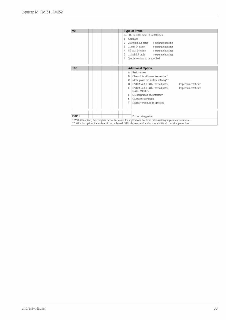
90 Type of Probe:
L4: 300 to 6000 mm/12 to 240 inch
1 Compact
2 2000 mm L4 cable > separate housing
3 ....mm L4 cable > separate housing
4 80 inch L4 cable > separate housing
5 ....inch L4 cable > separate housing
9 Special version, to be specified
100 Additional Option:
A Basic version
B Cleaned for silicone- free service*
C Metal probe rod surface refining**
D EN10204-3.1 (316L wetted parts), Inspection certificate
E EN10204-3.1 (316L wetted parts),
NACE MR0175
Inspection certificate
F SIL declaration of conformity
S GL marine certificate
Y Special version, to be specified
FMI51 Product designation
* With this option, the complete device is cleaned for applications free from paint-wetting impairment substances
** With this option, the surface of the probe rod (316L) is passivated and acts as additional corrosion protection
Liquicap M FMI51, FMI52
34 Endress+Hauser
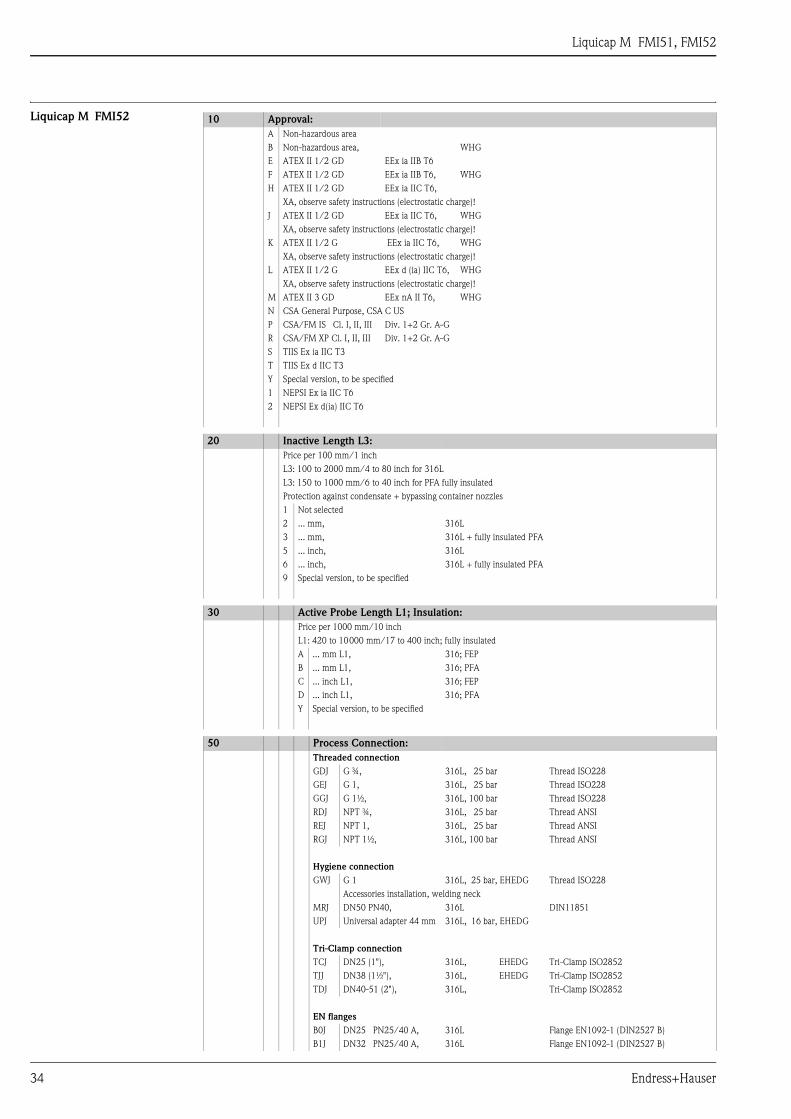
Liquicap M FMI52 10 Approval:
A Non-hazardous area
B Non-hazardous area, WHG
E ATEX II 1/2 GD EEx ia IIB T6
F ATEX II 1/2 GD EEx ia IIB T6, WHG
H ATEX II 1/2 GD EEx ia IIC T6,
XA, observe safety instructions (electrostatic charge)!
J ATEX II 1/2 GD EEx ia IIC T6, WHG
XA, observe safety instructions (electrostatic charge)!
K ATEX II 1/2 G EEx ia IIC T6, WHG
XA, observe safety instructions (electrostatic charge)!
L ATEX II 1/2 G EEx d (ia) IIC T6, WHG
XA, observe safety instructions (electrostatic charge)!
M ATEX II 3 GD EEx nA II T6, WHG
N CSA General Purpose, CSA C US
P CSA/FM IS Cl. I, II, III Div. 1+2 Gr. A-G
R CSA/FM XP Cl. I, II, III Div. 1+2 Gr. A-G
S TIIS Ex ia IIC T3
T TIIS Ex d IIC T3
Y Special version, to be specified
1 NEPSI Ex ia IIC T6
2 NEPSI Ex d(ia) IIC T6
20 Inactive Length L3:
Price per 100 mm/1 inch
L3: 100 to 2000 mm/4 to 80 inch for 316L
L3: 150 to 1000 mm/6 to 40 inch for PFA fully insulated
Protection against condensate + bypassing container nozzles
1 Not selected
2 ... mm, 316L
3 ... mm, 316L + fully insulated PFA
5 ... inch, 316L
6 ... inch, 316L + fully insulated PFA
9 Special version, to be specified
30 Active Probe Length L1; Insulation:
Price per 1000 mm/10 inch
L1: 420 to 10000 mm/17 to 400 inch; fully insulated
A ... mm L1, 316; FEP
B ... mm L1, 316; PFA
C ... inch L1, 316; FEP
D ... inch L1, 316; PFA
Y Special version, to be specified
50 Process Connection:
Threaded connection
GDJ G ¾, 316L, 25 bar Thread ISO228
GEJ G 1, 316L, 25 bar Thread ISO228
GGJ G 1½, 316L, 100 bar Thread ISO228
RDJ NPT ¾, 316L, 25 bar Thread ANSI
REJ NPT 1, 316L, 25 bar Thread ANSI
RGJ NPT 1½, 316L, 100 bar Thread ANSI
Hygiene connection
GWJ G 1 316L, 25 bar, EHEDG Thread ISO228
Accessories installation, welding neck
MRJ DN50 PN40, 316L DIN11851
UPJ Universal adapter 44 mm 316L, 16 bar, EHEDG
Tri-Clamp connection
TCJ DN25 (1"), 316L, EHEDG Tri-Clamp ISO2852
TJJ DN38 (1½"), 316L, EHEDG Tri-Clamp ISO2852
TDJ DN40-51 (2"), 316L, Tri-Clamp ISO2852
EN flanges
B0J DN25 PN25/40 A, 316L Flange EN1092-1 (DIN2527 B)
B1J DN32 PN25/40 A, 316L Flange EN1092-1 (DIN2527 B)
Liquicap M FMI51, FMI52
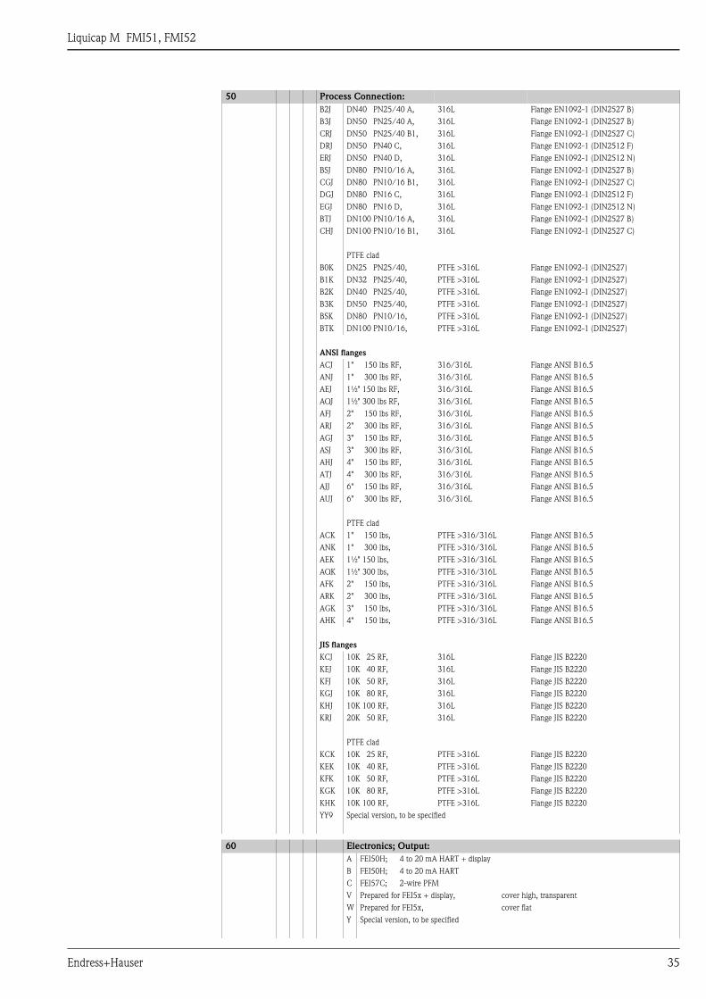
Endress+Hauser 35
B2J DN40 PN25/40 A, 316L Flange EN1092-1 (DIN2527 B)
B3J DN50 PN25/40 A, 316L Flange EN1092-1 (DIN2527 B)
CRJ DN50 PN25/40 B1, 316L Flange EN1092-1 (DIN2527 C)
DRJ DN50 PN40 C, 316L Flange EN1092-1 (DIN2512 F)
ERJ DN50 PN40 D, 316L Flange EN1092-1 (DIN2512 N)
BSJ DN80 PN10/16 A, 316L Flange EN1092-1 (DIN2527 B)
CGJ DN80 PN10/16 B1, 316L Flange EN1092-1 (DIN2527 C)
DGJ DN80 PN16 C, 316L Flange EN1092-1 (DIN2512 F)
EGJ DN80 PN16 D, 316L Flange EN1092-1 (DIN2512 N)
BTJ DN100 PN10/16 A, 316L Flange EN1092-1 (DIN2527 B)
CHJ DN100 PN10/16 B1, 316L Flange EN1092-1 (DIN2527 C)
PTFE clad
B0K DN25 PN25/40, PTFE >316L Flange EN1092-1 (DIN2527)
B1K DN32 PN25/40, PTFE >316L Flange EN1092-1 (DIN2527)
B2K DN40 PN25/40, PTFE >316L Flange EN1092-1 (DIN2527)
B3K DN50 PN25/40, PTFE >316L Flange EN1092-1 (DIN2527)
BSK DN80 PN10/16, PTFE >316L Flange EN1092-1 (DIN2527)
BTK DN100 PN10/16, PTFE >316L Flange EN1092-1 (DIN2527)
ANSI flanges
ACJ 1" 150 lbs RF, 316/316L Flange ANSI B16.5
ANJ 1" 300 lbs RF, 316/316L Flange ANSI B16.5
AEJ 1½" 150 lbs RF, 316/316L Flange ANSI B16.5
AQJ 1½" 300 lbs RF, 316/316L Flange ANSI B16.5
AFJ 2" 150 lbs RF, 316/316L Flange ANSI B16.5
ARJ 2" 300 lbs RF, 316/316L Flange ANSI B16.5
AGJ 3" 150 lbs RF, 316/316L Flange ANSI B16.5
ASJ 3" 300 lbs RF, 316/316L Flange ANSI B16.5
AHJ 4" 150 lbs RF, 316/316L Flange ANSI B16.5
ATJ 4" 300 lbs RF, 316/316L Flange ANSI B16.5
AJJ 6" 150 lbs RF, 316/316L Flange ANSI B16.5
AUJ 6" 300 lbs RF, 316/316L Flange ANSI B16.5
PTFE clad
ACK 1" 150 lbs, PTFE >316/316L Flange ANSI B16.5
ANK 1" 300 lbs, PTFE >316/316L Flange ANSI B16.5
AEK 1½" 150 lbs, PTFE >316/316L Flange ANSI B16.5
AQK 1½" 300 lbs, PTFE >316/316L Flange ANSI B16.5
AFK 2" 150 lbs, PTFE >316/316L Flange ANSI B16.5
ARK 2" 300 lbs, PTFE >316/316L Flange ANSI B16.5
AGK 3" 150 lbs, PTFE >316/316L Flange ANSI B16.5
AHK 4" 150 lbs, PTFE >316/316L Flange ANSI B16.5
JIS flanges
KCJ 10K 25 RF, 316L Flange JIS B2220
KEJ 10K 40 RF, 316L Flange JIS B2220
KFJ 10K 50 RF, 316L Flange JIS B2220
KGJ 10K 80 RF, 316L Flange JIS B2220
KHJ 10K 100 RF, 316L Flange JIS B2220
KRJ 20K 50 RF, 316L Flange JIS B2220
PTFE clad
KCK 10K 25 RF, PTFE >316L Flange JIS B2220
KEK 10K 40 RF, PTFE >316L Flange JIS B2220
KFK 10K 50 RF, PTFE >316L Flange JIS B2220
KGK 10K 80 RF, PTFE >316L Flange JIS B2220
KHK 10K 100 RF, PTFE >316L Flange JIS B2220
YY9 Special version, to be specified
60 Electronics; Output:
A FEI50H; 4 to 20 mA HART + display
B FEI50H; 4 to 20 mA HART
C FEI57C; 2-wire PFM
V Prepared for FEI5x + display, cover high, transparent
W Prepared for FEI5x, cover flat
Y Special version, to be specified
50 Process Connection:
Liquicap M FMI51, FMI52
36 Endress+Hauser
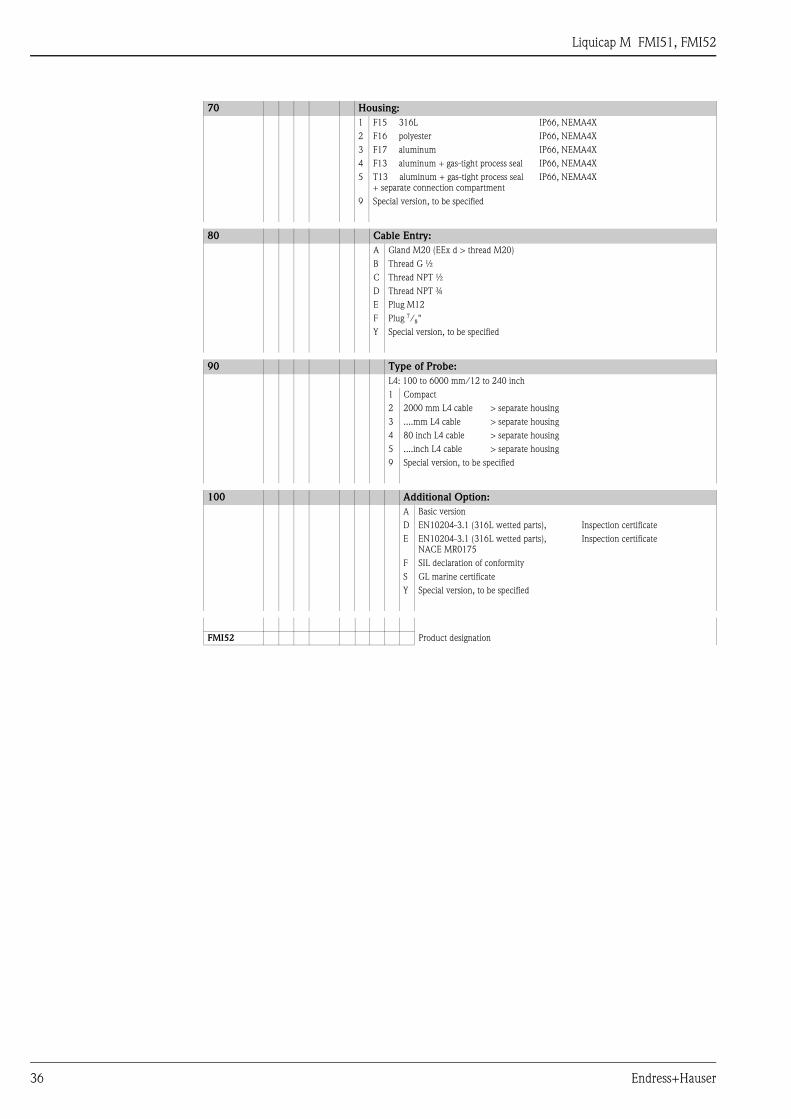
70 Housing:
1 F15 316L IP66, NEMA4X
2 F16 polyester IP66, NEMA4X
3 F17 aluminum IP66, NEMA4X
4 F13 aluminum + gas-tight process seal IP66, NEMA4X
5 T13 aluminum + gas-tight process seal
+ separate connection compartment
IP66, NEMA4X
9 Special version, to be specified
80 Cable Entry:
A Gland M20 (EEx d > thread M20)
B Thread G ½
C Thread NPT ½
D Thread NPT ¾
E Plug M12
F Plug 7/8"
Y Special version, to be specified
90 Type of Probe:
L4: 100 to 6000 mm/12 to 240 inch
1 Compact
2 2000 mm L4 cable > separate housing
3 ....mm L4 cable > separate housing
4 80 inch L4 cable > separate housing
5 ....inch L4 cable > separate housing
9 Special version, to be specified
100 Additional Option:
A Basic version
D EN10204-3.1 (316L wetted parts), Inspection certificate
E EN10204-3.1 (316L wetted parts),
NACE MR0175
Inspection certificate
F SIL declaration of conformity
S GL marine certificate
Y Special version, to be specified
FMI52 Product designation
Liquicap M FMI51, FMI52
Endress+Hauser 37
Accessories
Protective cover For F13 and F17 housing (only possible with flat cover!)
Order number: TSP17090
Shortening kit for FMI52 Order number: 942901-0001
Commubox FXA191, FXA195
HART
For intrinsically safe HART communication with ToF Tool/FieldCare via an RS232C interface or USB.
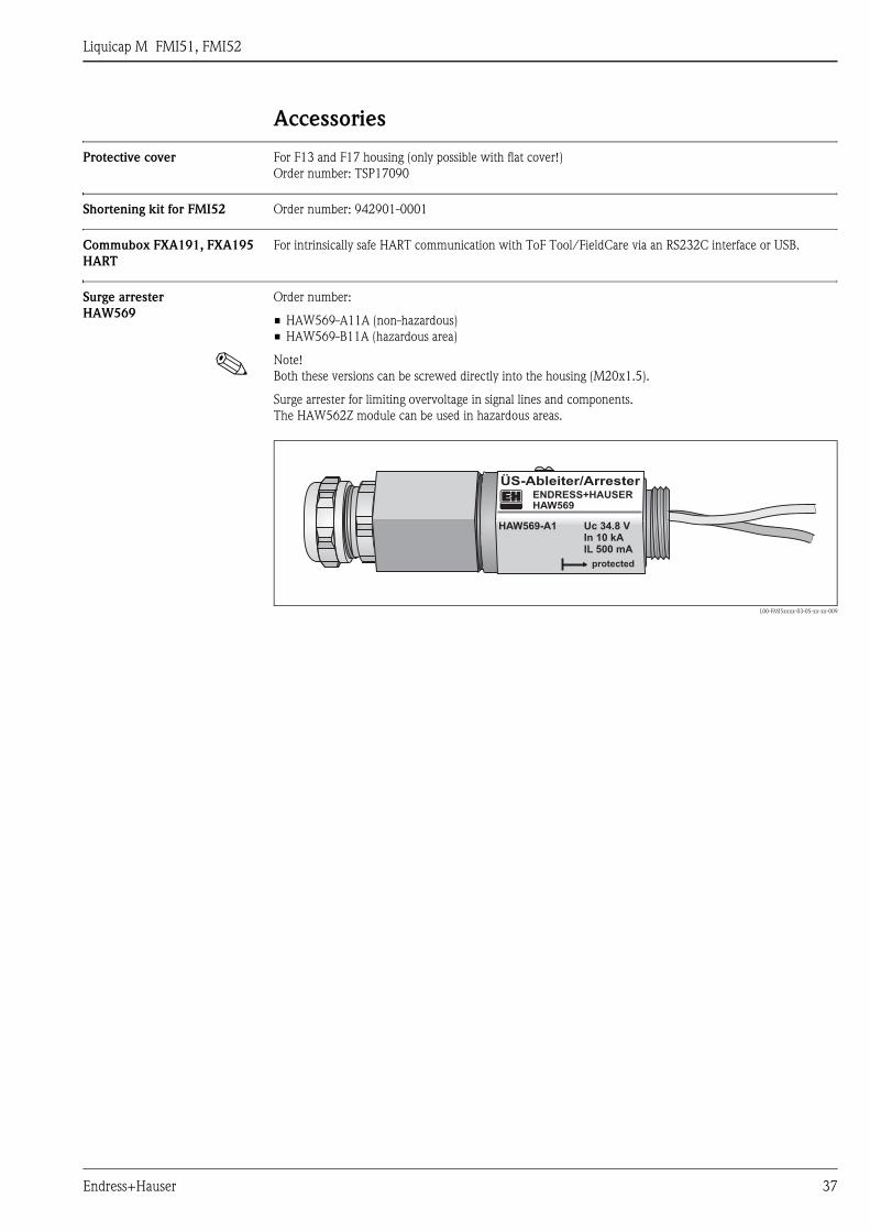
Surge arrester
HAW569
Order number:
• HAW569-A11A (non-hazardous)
• HAW569-B11A (hazardous area)
! Note!
Both these versions can be screwed directly into the housing (M20x1.5).
Surge arrester for limiting overvoltage in signal lines and components.
The HAW562Z module can be used in hazardous areas.
L00-FMI5xxxx-03-05-xx-xx-009
ÜS-Ableiter/ArresterENDRESS+HAUSERHAW569
HAW569-A1 Uc 34.8 VIn 10 kAIL 500 mA
protected
Liquicap M FMI51, FMI52
38 Endress+Hauser
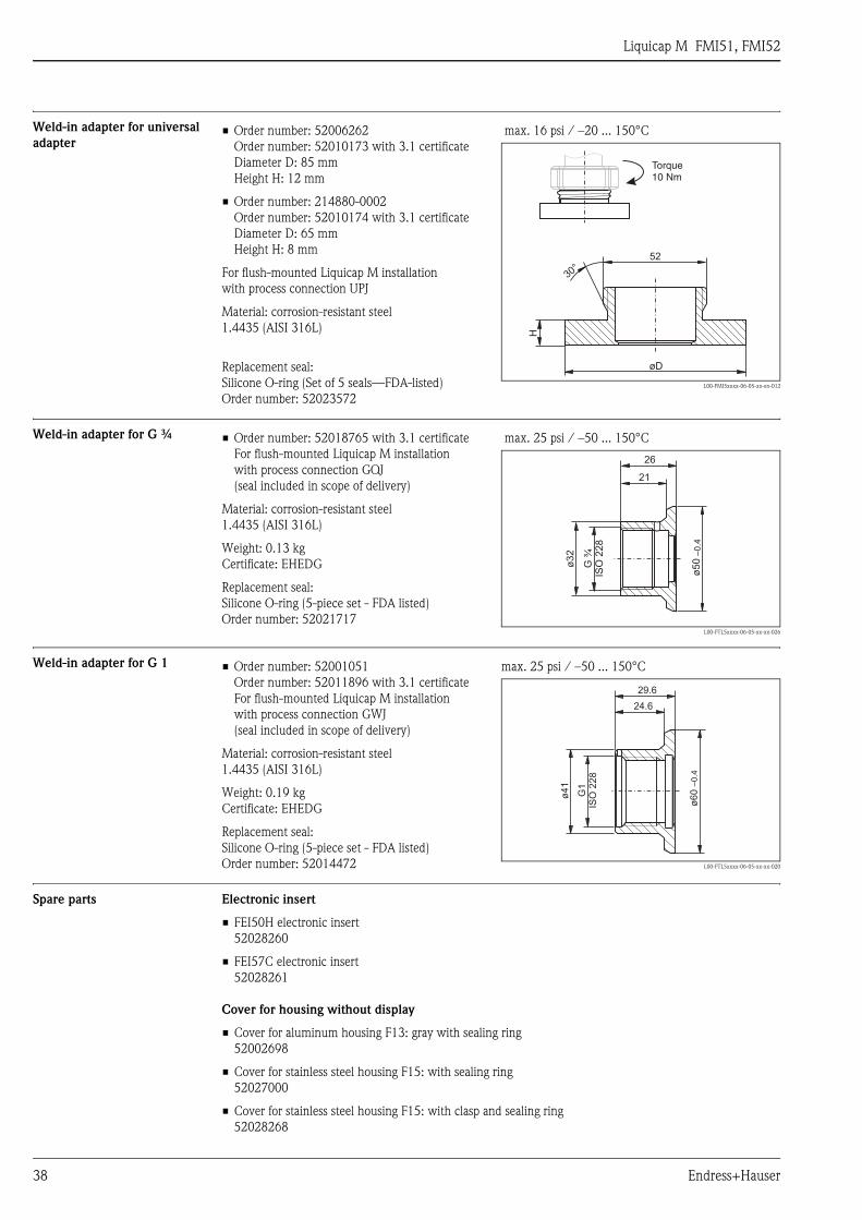
Weld-in adapter for universal
adapter
Weld-in adapter for G ¾
Weld-in adapter for G 1
Spare parts Electronic insert
• FEI50H electronic insert
52028260
• FEI57C electronic insert
52028261
Cover for housing without display
• Cover for aluminum housing F13: gray with sealing ring
52002698
• Cover for stainless steel housing F15: with sealing ring
52027000
• Cover for stainless steel housing F15: with clasp and sealing ring
52028268
• Order number: 52006262
Order number: 52010173 with 3.1 certificate
Diameter D: 85 mm
Height H: 12 mm
• Order number: 214880-0002
Order number: 52010174 with 3.1 certificate
Diameter D: 65 mm
Height H: 8 mm
For flush-mounted Liquicap M installation
with process connection UPJ
Material: corrosion-resistant steel
1.4435 (AISI 316L)
Replacement seal:
Silicone O-ring (Set of 5 seals—FDA-listed)
Order number: 52023572
max. 16 psi / –20 ... 150°C
L00-FMI5xxxx-06-05-xx-en-012
30°
H
øD
52
Torque10 Nm
• Order number: 52018765 with 3.1 certificate
For flush-mounted Liquicap M installation
with process connection GQJ
(seal included in scope of delivery)
Material: corrosion-resistant steel
1.4435 (AISI 316L)
Weight: 0.13 kg
Certificate: EHEDG
Replacement seal:
Silicone O-ring (5-piece set - FDA listed)
Order number: 52021717
max. 25 psi / –50 ... 150°C
L00-FTL5xxxx-06-05-xx-xx-026
–0.4
ø50
21
26
ø32
G¾
ISO
228
• Order number: 52001051
Order number: 52011896 with 3.1 certificate
For flush-mounted Liquicap M installation
with process connection GWJ
(seal included in scope of delivery)
Material: corrosion-resistant steel
1.4435 (AISI 316L)
Weight: 0.19 kg
Certificate: EHEDG
Replacement seal:
Silicone O-ring (5-piece set - FDA listed)
Order number: 52014472
max. 25 psi / –50 ... 150°C
L00-FTL5xxxx-06-05-xx-xx-020
ø6
0–0.4
24.6
29.6
ø4
1
G1
ISO
22
8
Liquicap M FMI51, FMI52
Endress+Hauser 39
• Cover for polyester housing F16, flat: gray with sealing ring
52025606
• Cover for aluminum housing F17, flat: with sealing ring
52002699
• Cover for aluminum housing T13, flat: gray with sealing ring/electronics compartment
52006903
• Cover for aluminum housing T13, flat: gray with sealing ring/connection compartment
52007103
Cover for housing with display
• Cover for stainless steel housing F15: with sight glass, clasp and sealing ring
52028267
• Cover for stainless steel housing F15: high, with sight glass and sealing ring
52028269
• Cover for stainless steel housing F15: high, with sight glass, clasp and sealing ring
71005440
• Cover for aluminum housing F13/F17: high, with sight glass and sealing ring
52028270
• Cover for aluminum housing T13: high, with sight glass/electronics compartment for EEx d
52028271
• Cover for polyester housing F16: high, with transparent housing and sealing ring
52025605
Display with holder
• Display with holder for electronic insert FEI50H
52028266
Seal set for stainless steel housing
• Seal set for stainless steel housing F15: with 5 sealing rings
52028179
Terminal module
• Terminal module 2-pin EEx d, RFI filter for T13 housing
71020804
Supplementary Documentation
! Note!
This documentation is available on the product pages at www.endress.com
Technical Information • Fieldgate FXA320, FXA520
TI369F/00/en
Operating Instructions • Liquicap M FMI51, FMI52 (PFM)
BA297F/00/en
• Liquicap M FMI51, FMI52 (HART)
BA298F/00/en
Certificates ATEX safety instructions
• Liquicap M FMI51, FMI52
ATEX II 1/2 G (EEx ia IIC/IIB T3 to T6), II 1/2 D IP65 T 85 °C
XA327F/00/a3
• Liquicap M FMI51, FMI52
ATEX II 1/2 G (EEx d (ia) IIC/IIB T3 to T6)
XA328F/00/a3
Overfill protection DIBt (WHG)
• Liquicap M FMI51, FMI52
ZE265F/00/de
Functional safety (SIL2)
• Liquicap M FMI51, FMI52
SD198F/00/en
Control Drawings
• Liquicap M FMI51, FMI52
FM
ZD220F/00/en
• Liquicap M FMI51, FMI52
CSA
ZD221F/00/en
Patents This product is protected by at least one of the patents listed below.
Further patents are under development.
• DE 203 00 901 U1
• DE 103 22 279,
WO 2004 102 133,
US 2005 003 9528
• DE 203 13 695,
WO 2005 025 015
Instruments International
Endress+HauserInstruments International AGKaegenstrasse 24153 ReinachSwitzerland
Tel. +41 61 715 81 00Fax +41 61 715 25 [email protected]
TI401F/00/en/01.07
FM+SGML 6.0 ProMoDo