Embed Size (px)
Citation preview
BA00298F/00/en/13.10
71123554
Valid as of software version:
FW: V 01.03.00
HW: V 02.00
Operating Instructions
Liquicap M FMI51, FMI52
FEI50H HART
Capacitive level measurement
Liquicap M FMI51, FMI52 Table of contents
2 Endress+Hauser
Table of contents
1 Safety instructions . . . . . . . . . . . . . . . . 3
1.1 Designated use . . . . . . . . . . . . . . . . . . . . . . . . . . . . 3
1.2 Installation, commissioning and operation . . . . . . . . 3
1.3 Operational safety . . . . . . . . . . . . . . . . . . . . . . . . . . 3
1.4 Notes on safety conventions and icons . . . . . . . . . . 4
2 Identification . . . . . . . . . . . . . . . . . . . . 5
2.1 Device designation . . . . . . . . . . . . . . . . . . . . . . . . . 5
2.2 Scope of delivery . . . . . . . . . . . . . . . . . . . . . . . . . 12
2.3 Certificates and approvals . . . . . . . . . . . . . . . . . . . 12
2.4 Trademarks . . . . . . . . . . . . . . . . . . . . . . . . . . . . . 12
3 Installation . . . . . . . . . . . . . . . . . . . . . 13
3.1 Quick installation guide . . . . . . . . . . . . . . . . . . . . 13
3.2 Incoming acceptance, transport, storage . . . . . . . . 13
3.3 Planning instructions . . . . . . . . . . . . . . . . . . . . . . 14
3.4 Measuring condition . . . . . . . . . . . . . . . . . . . . . . . 15
3.5 Minimum probe length for nonconductive media
(<1μs/cm) . . . . . . . . . . . . . . . . . . . . . . . . . . . . . . 16
3.6 Installation examples . . . . . . . . . . . . . . . . . . . . . . 16
3.7 With separate housing . . . . . . . . . . . . . . . . . . . . . 21
3.8 Installation instructions . . . . . . . . . . . . . . . . . . . . . 24
3.9 Post-installation check . . . . . . . . . . . . . . . . . . . . . 26
4 Wiring. . . . . . . . . . . . . . . . . . . . . . . . . 27
4.1 Recommendations for connection . . . . . . . . . . . . . 27
4.2 Wiring and connecting . . . . . . . . . . . . . . . . . . . . . 28
4.3 Post-connection check . . . . . . . . . . . . . . . . . . . . . 31
5 Operation . . . . . . . . . . . . . . . . . . . . . . 32
5.1 Operating options . . . . . . . . . . . . . . . . . . . . . . . . . 32
5.2 Error messages . . . . . . . . . . . . . . . . . . . . . . . . . . . 44
5.3 Locking/unlocking configuration . . . . . . . . . . . . . 45
5.4 Resetting to factory setting (reset) . . . . . . . . . . . . . 45
5.5 Operation via FieldCare Device Setup . . . . . . . . . . 46
5.6 Operation via HART handheld terminal DXR375 . 47
6 Commissioning. . . . . . . . . . . . . . . . . . 48
6.1 Installation and function check . . . . . . . . . . . . . . . 48
6.2 Basic setup without the display/operating module . 48
6.3 "Basic setup" menu Commissioning with display
and operating module . . . . . . . . . . . . . . . . . . . . . . 53
6.4 "Safety setting" menu . . . . . . . . . . . . . . . . . . . . . . 59
6.5 "Linearization" menu . . . . . . . . . . . . . . . . . . . . . . 63
6.6 "Output" menu . . . . . . . . . . . . . . . . . . . . . . . . . . . 69
6.7 "Device properties" menu . . . . . . . . . . . . . . . . . . . 73
6.8 Operation . . . . . . . . . . . . . . . . . . . . . . . . . . . . . . . 77
6.9 FieldCare: operating program from Endress+Hauser 77
7 Maintenance . . . . . . . . . . . . . . . . . . . . 83
8 Accessories . . . . . . . . . . . . . . . . . . . . . 84
8.1 Protective cover . . . . . . . . . . . . . . . . . . . . . . . . . . 84
8.2 Shortening set for FMI52 . . . . . . . . . . . . . . . . . . . 84
8.3 Commubox FXA195 HART . . . . . . . . . . . . . . . . . . 84
8.4 HAW56x surge arrester . . . . . . . . . . . . . . . . . . . . 84
8.5 Weld-in adapter . . . . . . . . . . . . . . . . . . . . . . . . . . 84
9 Troubleshooting. . . . . . . . . . . . . . . . . . 85
9.1 Error messages at electronic insert . . . . . . . . . . . . . 85
9.2 System error messages . . . . . . . . . . . . . . . . . . . . . 85
9.3 Possible measuring errors . . . . . . . . . . . . . . . . . . . 88
9.4 Spare Parts . . . . . . . . . . . . . . . . . . . . . . . . . . . . . . 88
9.5 Return . . . . . . . . . . . . . . . . . . . . . . . . . . . . . . . . . 89
9.6 Disposal . . . . . . . . . . . . . . . . . . . . . . . . . . . . . . . . 89
9.7 Software history . . . . . . . . . . . . . . . . . . . . . . . . . . 89
10 Technical data . . . . . . . . . . . . . . . . . . . 90
10.1 Technical data: probe . . . . . . . . . . . . . . . . . . . . . . 90
10.2 Input . . . . . . . . . . . . . . . . . . . . . . . . . . . . . . . . . . 90
10.3 Output . . . . . . . . . . . . . . . . . . . . . . . . . . . . . . . . . 91
10.4 Performance characteristics . . . . . . . . . . . . . . . . . . 91
10.5 Operating conditions: Environment . . . . . . . . . . . . 93
10.6 Operating conditions: Process . . . . . . . . . . . . . . . . 94
10.7 Certificates and approvals . . . . . . . . . . . . . . . . . . . 97
10.8 Documentation . . . . . . . . . . . . . . . . . . . . . . . . . . . 97
11 Operating menu. . . . . . . . . . . . . . . . . . 99
11.1 "Basic setup" menu
Commissioning with display and operating module 99
11.2 "Safety setting" menu . . . . . . . . . . . . . . . . . . . . . 100
11.3 "Linearization" menu . . . . . . . . . . . . . . . . . . . . . 101
11.4 "Output" menu . . . . . . . . . . . . . . . . . . . . . . . . . . 102
11.5 "Device properties" menu . . . . . . . . . . . . . . . . . . 103
Index . . . . . . . . . . . . . . . . . . . . . . . . . . . . . 104

Liquicap M FMI51, FMI52 Safety instructions
Endress+Hauser 3
1 Safety instructions
1.1 Designated use
Liquicap M FMI51, FMI52 are compact, capacitance level transmitters for the continuous
measurement of liquids.
1.2 Installation, commissioning and operation
Liquicap M is designed to meet state-of-the-art safety regulations and complies with the applicable
requirements and EC Directives. If used improperly or other than intended, the device can,
however, be a source of application-related danger, e.g. product overflow as a result of incorrect
installation or configuration. For this reason, installation, electrical connection, commissioning,
operation and maintenance of the measuring system must only be carried out by trained technical
personnel authorized to perform such work by the owner-operator. The technical personnel must
have read and understood these Operating Instructions and must follow the instructions they
contain. The device may only be repaired or modified if expressly permitted in the Operating
Instructions.
1.3 Operational safety
When performing configuration, testing and maintenance work on the device, alternative
supervisory measures must be taken to guarantee the operational safety and process safety.
1.3.1 Ex area
When using the measuring system in Ex-areas, the appropriate national standards and regulations
have to be observed. Separate Ex documentation, which constitutes an integral part of this
documentation, is supplied with the device. The installation procedures, connection data and safety
instructions it contains must be observed.
• Make sure that the technical staff has adequate training.
• The special measuring and safety-related requirements for the measuring points must be
observed.
Safety instructions Liquicap M FMI51, FMI52
4 Endress+Hauser
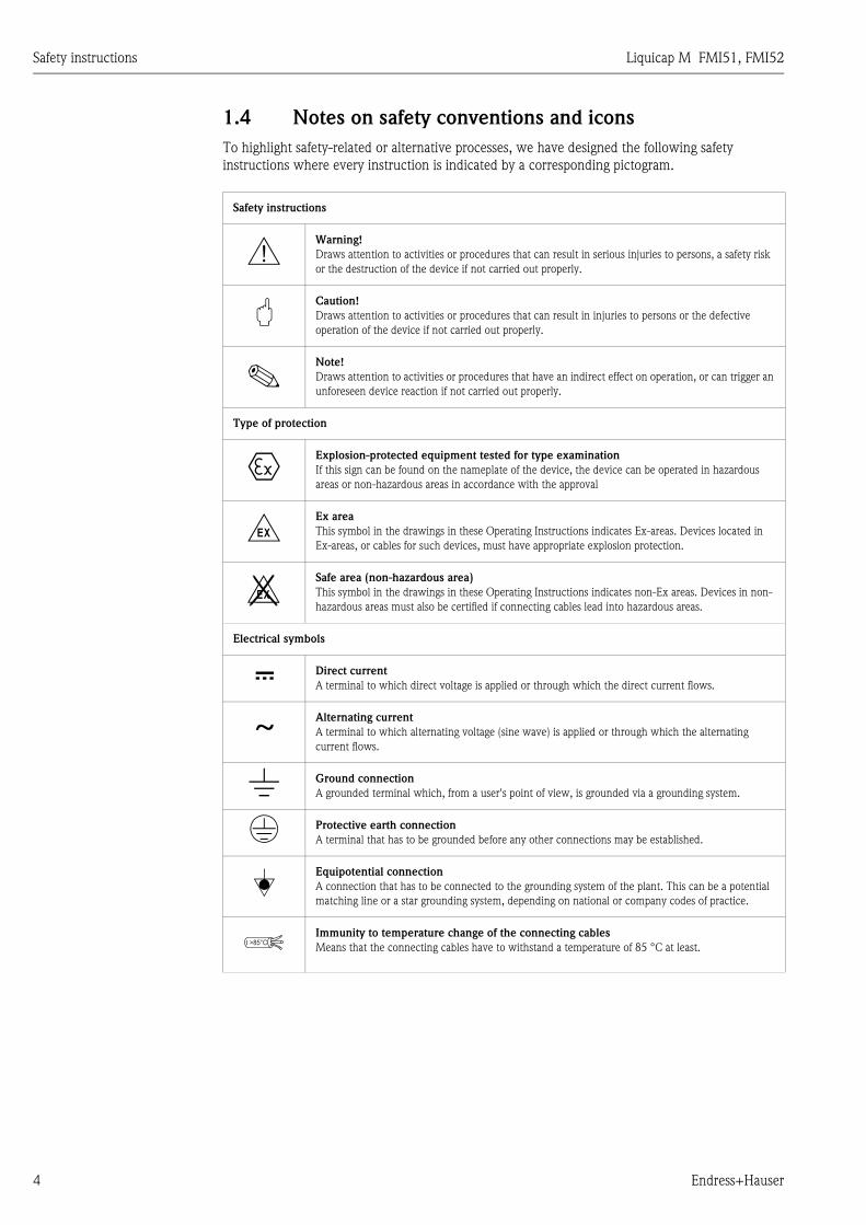
1.4 Notes on safety conventions and icons
To highlight safety-related or alternative processes, we have designed the following safety
instructions where every instruction is indicated by a corresponding pictogram.
Safety instructions
#Warning!
Draws attention to activities or procedures that can result in serious injuries to persons, a safety risk
or the destruction of the device if not carried out properly.
"Caution!
Draws attention to activities or procedures that can result in injuries to persons or the defective
operation of the device if not carried out properly.
!Note!
Draws attention to activities or procedures that have an indirect effect on operation, or can trigger an
unforeseen device reaction if not carried out properly.
Type of protection
0Explosion-protected equipment tested for type examination
If this sign can be found on the nameplate of the device, the device can be operated in hazardous
areas or non-hazardous areas in accordance with the approval
-Ex area
This symbol in the drawings in these Operating Instructions indicates Ex-areas. Devices located in
Ex-areas, or cables for such devices, must have appropriate explosion protection.
.Safe area (non-hazardous area)
This symbol in the drawings in these Operating Instructions indicates non-Ex areas. Devices in non-
hazardous areas must also be certified if connecting cables lead into hazardous areas.
Electrical symbols
% Direct current
A terminal to which direct voltage is applied or through which the direct current flows.
&Alternating current
A terminal to which alternating voltage (sine wave) is applied or through which the alternating
current flows.
) Ground connection
A grounded terminal which, from a user's point of view, is grounded via a grounding system.
* Protective earth connection
A terminal that has to be grounded before any other connections may be established.
+Equipotential connection
A connection that has to be connected to the grounding system of the plant. This can be a potential
matching line or a star grounding system, depending on national or company codes of practice.
Immunity to temperature change of the connecting cables
Means that the connecting cables have to withstand a temperature of 85 °C at least.t >85°C
Liquicap M FMI51, FMI52 Identification
Endress+Hauser 5
2 Identification
2.1 Device designation
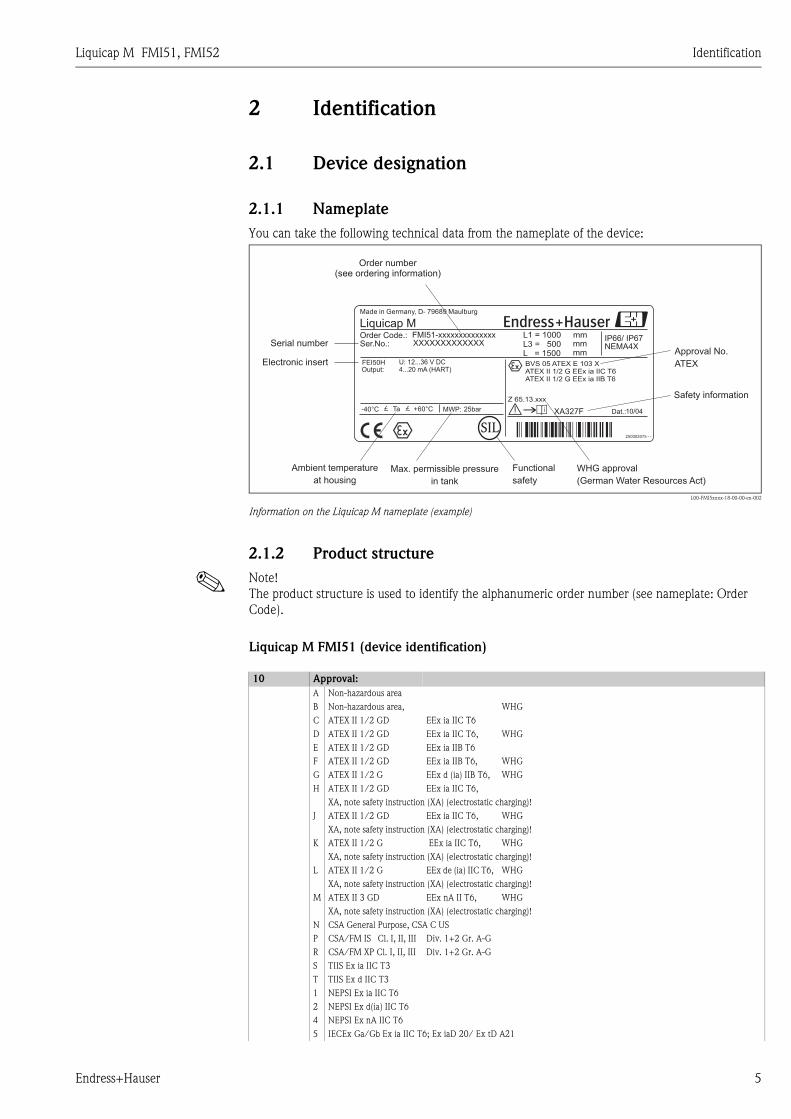
2.1.1 Nameplate
You can take the following technical data from the nameplate of the device:
L00-FMI5xxxx-18-00-00-en-002
Information on the Liquicap M nameplate (example)
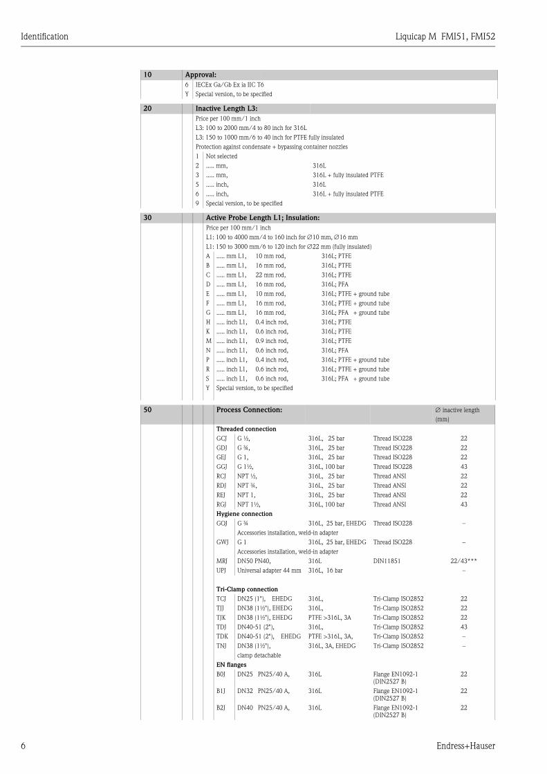
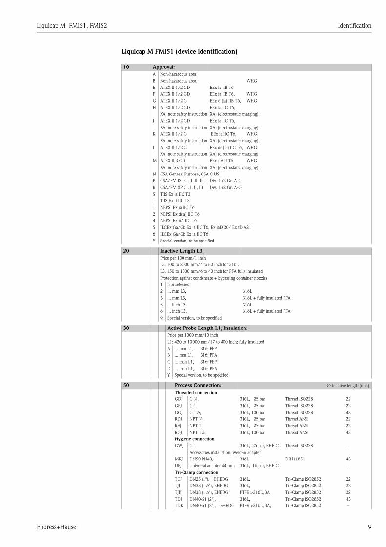
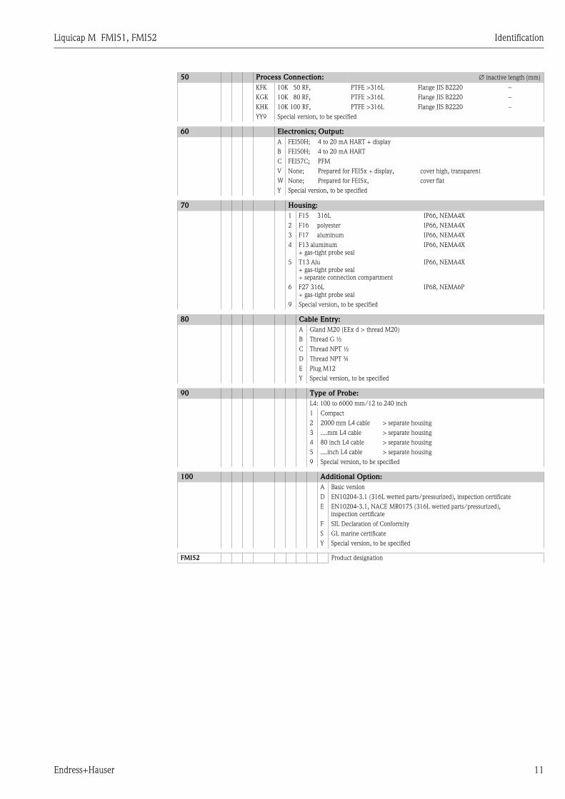
2.1.2 Product structure
! Note!
The product structure is used to identify the alphanumeric order number (see nameplate: Order
Code).
Liquicap M FMI51 (device identification)
SIL250002075 - -
Dat.:
IP66/ IP67NEMA4X
MWP:£ Ta £ +60°C-40°C
Liquicap MOrder Code.:Ser.No.:
XA327F
mm
10/04
Made in Germany, D- 79689 Maulburg
Output:
XXXXXXXXXXXXXL1 = 1000L3 = 500L = 1500
mm
FEI50H
FMI51-xxxxxxxxxxxxxx
U: 12...36 V DC
25bar
BVS 05 ATEX E 103 XATEX II 1/2 G EEx ia IIC T6ATEX II 1/2 G EEx ia IIB T6
Z 65.13.xxx
4...20 mA (HART)
mm
Functional
safety
Order number(see ordering information)
Approval No.
ATEX
WHG approval
(German Water Resources Act)
Safety information
Max. permissible pressure
in tank
Serial number
Ambient temperature
at housing
Electronic insert
10 Approval:
A Non-hazardous area
B Non-hazardous area, WHG
C ATEX II 1/2 GD EEx ia IIC T6
D ATEX II 1/2 GD EEx ia IIC T6, WHG
E ATEX II 1/2 GD EEx ia IIB T6
F ATEX II 1/2 GD EEx ia IIB T6, WHG
G ATEX II 1/2 G EEx d (ia) IIB T6, WHG
H ATEX II 1/2 GD EEx ia IIC T6,
XA, note safety instruction (XA) (electrostatic charging)!
J ATEX II 1/2 GD EEx ia IIC T6, WHG
XA, note safety instruction (XA) (electrostatic charging)!
K ATEX II 1/2 G EEx ia IIC T6, WHG
XA, note safety instruction (XA) (electrostatic charging)!
L ATEX II 1/2 G EEx de (ia) IIC T6, WHG
XA, note safety instruction (XA) (electrostatic charging)!
M ATEX II 3 GD EEx nA II T6, WHG
XA, note safety instruction (XA) (electrostatic charging)!
N CSA General Purpose, CSA C US
P CSA/FM IS Cl. I, II, III Div. 1+2 Gr. A-G
R CSA/FM XP Cl. I, II, III Div. 1+2 Gr. A-G
S TIIS Ex ia IIC T3
T TIIS Ex d IIC T3
1 NEPSI Ex ia IIC T6
2 NEPSI Ex d(ia) IIC T6
4 NEPSI Ex nA IIC T6
5 IECEx Ga/Gb Ex ia IIC T6; Ex iaD 20/ Ex tD A21
Identification Liquicap M FMI51, FMI52
6 Endress+Hauser
6 IECEx Ga/Gb Ex ia IIC T6
Y Special version, to be specified
20 Inactive Length L3:
Price per 100 mm/1 inch
L3: 100 to 2000 mm/4 to 80 inch for 316L
L3: 150 to 1000 mm/6 to 40 inch for PTFE fully insulated
Protection against condensate + bypassing container nozzles
1 Not selected
2 ..... mm, 316L
3 ..... mm, 316L + fully insulated PTFE
5 ..... inch, 316L
6 ..... inch, 316L + fully insulated PTFE
9 Special version, to be specified
30 Active Probe Length L1; Insulation:
Price per 100 mm/1 inch
L1: 100 to 4000 mm/4 to 160 inch for ∅10 mm, ∅16 mm
L1: 150 to 3000 mm/6 to 120 inch for ∅22 mm (fully insulated)
A ..... mm L1, 10 mm rod, 316L; PTFE
B ..... mm L1, 16 mm rod, 316L; PTFE
C ..... mm L1, 22 mm rod, 316L; PTFE
D ..... mm L1, 16 mm rod, 316L; PFA
E ..... mm L1, 10 mm rod, 316L; PTFE + ground tube
F ..... mm L1, 16 mm rod, 316L; PTFE + ground tube
G ..... mm L1, 16 mm rod, 316L; PFA + ground tube
H ..... inch L1, 0.4 inch rod, 316L; PTFE
K ..... inch L1, 0.6 inch rod, 316L; PTFE
M ..... inch L1, 0.9 inch rod, 316L; PTFE
N ..... inch L1, 0.6 inch rod, 316L; PFA
P ..... inch L1, 0.4 inch rod, 316L; PTFE + ground tube
R ..... inch L1, 0.6 inch rod, 316L; PTFE + ground tube
S ..... inch L1, 0.6 inch rod, 316L; PFA + ground tube
Y Special version, to be specified
50 Process Connection: ∅ inactive length
(mm)
Threaded connection
GCJ G ½, 316L, 25 bar Thread ISO228 22
GDJ G ¾, 316L, 25 bar Thread ISO228 22
GEJ G 1, 316L, 25 bar Thread ISO228 22
GGJ G 1½, 316L, 100 bar Thread ISO228 43
RCJ NPT ½, 316L, 25 bar Thread ANSI 22
RDJ NPT ¾, 316L, 25 bar Thread ANSI 22
REJ NPT 1, 316L, 25 bar Thread ANSI 22
RGJ NPT 1½, 316L, 100 bar Thread ANSI 43
Hygiene connection
GQJ G ¾ 316L, 25 bar, EHEDG Thread ISO228 –
Accessories installation, weld-in adapter
GWJ G 1 316L, 25 bar, EHEDG Thread ISO228 –
Accessories installation, weld-in adapter
MRJ DN50 PN40, 316L DIN11851 22/43***
UPJ Universal adapter 44 mm 316L, 16 bar –
Tri-Clamp connection
TCJ DN25 (1"), EHEDG 316L, Tri-Clamp ISO2852 22
TJJ DN38 (1½"), EHEDG 316L, Tri-Clamp ISO2852 22
TJK DN38 (1½"), EHEDG PTFE >316L, 3A Tri-Clamp ISO2852 22
TDJ DN40-51 (2"), 316L, Tri-Clamp ISO2852 43
TDK DN40-51 (2"), EHEDG PTFE >316L, 3A, Tri-Clamp ISO2852 –
TNJ DN38 (1½"), 316L, 3A, EHEDG Tri-Clamp ISO2852 –
clamp detachable
EN flanges
B0J DN25 PN25/40 A, 316L Flange EN1092-1
(DIN2527 B)
22
B1J DN32 PN25/40 A, 316L Flange EN1092-1
(DIN2527 B)
22
B2J DN40 PN25/40 A, 316L Flange EN1092-1
(DIN2527 B)
22
10 Approval:

Liquicap M FMI51, FMI52 Identification
Endress+Hauser 7
B3J DN50 PN25/40 A, 316L Flange EN1092-1
(DIN2527 B)
22/43***
CRJ DN50 PN25/40 B1, 316L Flange EN1092-1
(DIN2527 C)
43
DRJ DN50 PN40 C, 316L Flange EN1092-1
(DIN2512 F)
43
ERJ DN50 PN40 D, 316L Flange EN1092-1
(DIN2512 N)
43
BSJ DN80 PN10/16 A, 316L Flange EN1092-1
(DIN2527 B)
43
CGJ DN80 PN10/16 B1, 316L Flange EN1092-1
(DIN2527 C)
43
DGJ DN80 PN16 C, 316L Flange EN1092-1
(DIN2512 F)
43
EGJ DN80 PN16 D, 316L Flange EN1092-1
(DIN2512 N)
43
BTJ DN100 PN10/16 A, 316L Flange EN1092-1
(DIN2527 B)
43
CHJ DN100 PN10/16 B1, 316L Flange EN1092-1
(DIN2527 C)
43
PTFE clad
B0K DN25 PN25/40, PTFE >316L Flange EN1092-1
(DIN2527)
–
B1K DN32 PN25/40, PTFE >316L Flange EN1092-1
(DIN2527)
–
B2K DN40 PN25/40, PTFE >316L Flange EN1092-1
(DIN2527)
–
B3K DN50 PN25/40, PTFE >316L Flange EN1092-1
(DIN2527)
–
BSK DN80 PN10/16, PTFE >316L Flange EN1092-1
(DIN2527)
–
BTK DN100 PN10/16, PTFE >316L Flange EN1092-1
(DIN2527)
–
ANSI flanges
ACJ 1" 150 lbs RF, 316/316L Flange ANSI B16.5 22
ANJ 1" 300 lbs RF, 316/316L Flange ANSI B16.5 22
AEJ 1½" 150 lbs RF, 316/316L Flange ANSI B16.5 22
AQJ 1½" 300 lbs RF, 316/316L Flange ANSI B16.5 22
AFJ 2" 150 lbs RF, 316/316L Flange ANSI B16.5 22/43***
ARJ 2" 300 lbs RF, 316/316L Flange ANSI B16.5 22/43***
AGJ 3" 150 lbs RF, 316/316L Flange ANSI B16.5 43
ASJ 3" 300 lbs RF, 316/316L Flange ANSI B16.5 43
AHJ 4" 150 lbs RF, 316/316L Flange ANSI B16.5 43
ATJ 4" 300 lbs RF, 316/316L Flange ANSI B16.5 43
AJJ 6" 150 lbs RF, 316/316L Flange ANSI B16.5 43
AUJ 6" 300 lbs RF, 316/316L Flange ANSI B16.5 43
PTFE clad
ACK 1" 150 lbs, PTFE >316/316L Flange ANSI B16.5 –
ANK 1" 300 lbs, PTFE >316/316L Flange ANSI B16.5 –
AEK 1½" 150 lbs, PTFE >316/316L Flange ANSI B16.5 –
AQK 1½" 300 lbs, PTFE >316/316L Flange ANSI B16.5 –
AFK 2" 150 lbs, PTFE >316/316L Flange ANSI B16.5 –
ARK 2" 300 lbs, PTFE >316/316L Flange ANSI B16.5 –
AGK 3" 150 lbs, PTFE >316/316L Flange ANSI B16.5 –
AHK 4" 150 lbs, PTFE >316/316L Flange ANSI B16.5 –
JIS flanges
KCJ 10K 25 RF, 316L Flange JIS B2220 22
KEJ 10K 40 RF, 316L Flange JIS B2220 22
KFJ 10K 50 RF, 316L Flange JIS B2220 22/43***
KGJ 10K 80 RF, 316L Flange JIS B2220 22/43***
KHJ 10K 100 RF, 316L Flange JIS B2220 22/43***
KRJ 20K 50 RF, 316L Flange JIS B2220 43
PTFE clad
KCK 10K 25 RF, PTFE >316L Flange JIS B2220 –
KEK 10K 40 RF, PTFE >316L Flange JIS B2220 –
KFK 10K 50 RF, PTFE >316L Flange JIS B2220 –
KGK 10K 80 RF, PTFE >316L Flange JIS B2220 –
KHK 10K 100 RF, PTFE >316L Flange JIS B2220 –
YY9 Special version, to be specified
50 Process Connection: ∅ inactive length
(mm)

Identification Liquicap M FMI51, FMI52
8 Endress+Hauser
60 Electronics; Output:
A FEI50H; 4 to 20 mA HART + display
B FEI50H; 4 to 20 mA HART
C FEI57C; PFM
V None; Prepared for FEI5x + display, cover high, transparent
W None; Prepared for FEI5x, cover flat
Y Special version, to be specified
70 Housing:
1 F15 316L IP66, NEMA4X
2 F16 polyester IP66, NEMA4X
3 F17 aluminum IP66, NEMA4X
4 F13 aluminum
+ gas-tight probe seal
IP66, NEMA4X
5 T13 aluminum
+ gas-tight probe seal
+ separate connection compartment
IP66, NEMA4X
6 F27 316L
+ gas-tight probe seal
IP68, NEMA6P
9 Special version, to be specified
80 Cable Entry:
A Gland M20 (EEx d > thread M20)
B Thread G ½
C Thread NPT ½
D Thread NPT ¾
E Plug M12
Y Special version, to be specified
90 Type of Probe:
L4: 300 to 6000 mm/12 to 240 inch
1 Compact
2 2000 mm L4 cable > separate housing
3 ....mm L4 cable > separate housing
4 80 inch L4 cable > separate housing
5 ....inch L4 cable > separate housing
9 Special version, to be specified
100 Additional Option:
A Basic version
B PWIS free, PWIS = paint-wetting impairment
substances
C Metal probe rod surface refining**
D EN10204-3.1, (316L wetted parts/pressurized), inspection certificate
E EN10204-3.1, NACE MR0175 (316L wetted parts/pressurized),
inspection certificate
F SIL Declaration of Conformity
S GL marine certificate
Y Special version, to be specified
FMI51 Product designation
* With this option, the complete device is cleaned for applications free from paint-wetting impairment substances.
** With this option, the surface of the probe rod (316L) is passivated and acts as additional corrosion protection
*** Depends on probe rod ∅ (10 mm -> 22 mm; 16 mm -> 43 mm; 22 mm-> 22 mm rod not available with inactive length)
Liquicap M FMI51, FMI52 Identification
Endress+Hauser 9
Liquicap M FMI51 (device identification)
10 Approval:
A Non-hazardous area
B Non-hazardous area, WHG
E ATEX II 1/2 GD EEx ia IIB T6
F ATEX II 1/2 GD EEx ia IIB T6, WHG
G ATEX II 1/2 G EEx d (ia) IIB T6, WHG
H ATEX II 1/2 GD EEx ia IIC T6,
XA, note safety instruction (XA) (electrostatic charging)!
J ATEX II 1/2 GD EEx ia IIC T6,
XA, note safety instruction (XA) (electrostatic charging)!
K ATEX II 1/2 G EEx ia IIC T6, WHG
XA, note safety instruction (XA) (electrostatic charging)!
L ATEX II 1/2 G EEx de (ia) IIC T6, WHG
XA, note safety instruction (XA) (electrostatic charging)!
M ATEX II 3 GD EEx nA II T6, WHG
XA, note safety instruction (XA) (electrostatic charging)!
N CSA General Purpose, CSA C US
P CSA/FM IS Cl. I, II, III Div. 1+2 Gr. A-G
R CSA/FM XP Cl. I, II, III Div. 1+2 Gr. A-G
S TIIS Ex ia IIC T3
T TIIS Ex d IIC T3
1 NEPSI Ex ia IIC T6
2 NEPSI Ex d(ia) IIC T6
4 NEPSI Ex nA IIC T6
5 IECEx Ga/Gb Ex ia IIC T6; Ex iaD 20/ Ex tD A21
6 IECEx Ga/Gb Ex ia IIC T6
Y Special version, to be specified
20 Inactive Length L3:
Price per 100 mm/1 inch
L3: 100 to 2000 mm/4 to 80 inch for 316L
L3: 150 to 1000 mm/6 to 40 inch for PFA fully insulated
Protection against condensate + bypassing container nozzles
1 Not selected
2 ... mm L3, 316L
3 ... mm L3, 316L + fully insulated PFA
5 ... inch L3, 316L
6 ... inch L3, 316L + fully insulated PFA
9 Special version, to be specified
30 Active Probe Length L1; Insulation:
Price per 1000 mm/10 inch
L1: 420 to 10000 mm/17 to 400 inch; fully insulated
A ... mm L1, 316; FEP
B ... mm L1, 316; PFA
C ... inch L1, 316; FEP
D ... inch L1, 316; PFA
Y Special version, to be specified
50 Process Connection: ∅ inactive length (mm)
Threaded connection
GDJ G ¾, 316L, 25 bar Thread ISO228 22
GEJ G 1, 316L, 25 bar Thread ISO228 22
GGJ G 1½, 316L, 100 bar Thread ISO228 43
RDJ NPT ¾, 316L, 25 bar Thread ANSI 22
REJ NPT 1, 316L, 25 bar Thread ANSI 22
RGJ NPT 1½, 316L, 100 bar Thread ANSI 43
Hygiene connection
GWJ G 1 316L, 25 bar, EHEDG Thread ISO228 –
Accessories installation, weld-in adapter
MRJ DN50 PN40, 316L DIN11851 43
UPJ Universal adapter 44 mm 316L, 16 bar, EHEDG –
Tri-Clamp connection
TCJ DN25 (1"), EHEDG 316L, Tri-Clamp ISO2852 22
TJJ DN38 (1½"), EHEDG 316L, Tri-Clamp ISO2852 22
TJK DN38 (1½"), EHEDG PTFE >316L, 3A Tri-Clamp ISO2852 22
TDJ DN40-51 (2"), 316L, Tri-Clamp ISO2852 43
TDK DN40-51 (2"), EHEDG PTFE >316L, 3A, Tri-Clamp ISO2852 –

Identification Liquicap M FMI51, FMI52
10 Endress+Hauser
EN flanges
B0J DN25 PN25/40 A, 316L Flange EN1092-1
(DIN2527 B)
22
B1J DN32 PN25/40 A, 316L Flange EN1092-1
(DIN2527 B)
22
B2J DN40 PN25/40 A, 316L Flange EN1092-1
(DIN2527 B)
22
B3J DN50 PN25/40 A, 316L Flange EN1092-1
(DIN2527 B)
43
CRJ DN50 PN25/40 B1, 316L Flange EN1092-1
(DIN2527 C)
43
DRJ DN50 PN40 C, 316L Flange EN1092-1
(DIN2512 F)
43
ERJ DN50 PN40 D, 316L Flange EN1092-1
(DIN2512 N)
43
BSJ DN80 PN10/16 A, 316L Flange EN1092-1
(DIN2527 B)
43
CGJ DN80 PN10/16 B1, 316L Flange EN1092-1
(DIN2527 C)
43
DGJ DN80 PN16 C, 316L Flange EN1092-1
(DIN2512 F)
43
EGJ DN80 PN16 D, 316L Flange EN1092-1
(DIN2512 N)
43
BTJ DN100 PN10/16 A, 316L Flange EN1092-1
(DIN2527 B)
43
CHJ DN100 PN10/16 B1, 316L Flange EN1092-1
(DIN2527 C)
43
PTFE clad
B0K DN25 PN25/40, PTFE >316L Flange EN1092-1
(DIN2527)
–
B1K DN32 PN25/40, PTFE >316L Flange EN1092-1
(DIN2527)
–
B2K DN40 PN25/40, PTFE >316L Flange EN1092-1
(DIN2527)
–
B3K DN50 PN25/40, PTFE >316L Flange EN1092-1
(DIN2527)
–
BSK DN80 PN10/16, PTFE >316L Flange EN1092-1
(DIN2527)
–
BTK DN100 PN10/16, PTFE >316L Flange EN1092-1
(DIN2527)
–
ANSI flanges
ACJ 1" 150 lbs RF, 316/316L Flange ANSI B16.5 22
ANJ 1" 300 lbs RF, 316/316L Flange ANSI B16.5 22
AEJ 1½" 150 lbs RF, 316/316L Flange ANSI B16.5 22
AQJ 1½" 300 lbs RF, 316/316L Flange ANSI B16.5 43
AFJ 2" 150 lbs RF, 316/316L Flange ANSI B16.5 43
ARJ 2" 300 lbs RF, 316/316L Flange ANSI B16.5 43
AGJ 3" 150 lbs RF, 316/316L Flange ANSI B16.5 43
ASJ 3" 300 lbs RF, 316/316L Flange ANSI B16.5 43
AHJ 4" 150 lbs RF, 316/316L Flange ANSI B16.5 43
ATJ 4" 300 lbs RF, 316/316L Flange ANSI B16.5 43
AJJ 6" 150 lbs RF, 316/316L Flange ANSI B16.5 43
AUJ 6" 300 lbs RF, 316/316L Flange ANSI B16.5 43
PTFE clad
ACK 1" 150 lbs, PTFE >316/316L Flange ANSI B16.5 –
ANK 1" 300 lbs, PTFE >316/316L Flange ANSI B16.5 –
AEK 1½" 150 lbs, PTFE >316/316L Flange ANSI B16.5 –
AQK 1½" 300 lbs, PTFE >316/316L Flange ANSI B16.5 –
AFK 2" 150 lbs, PTFE >316/316L Flange ANSI B16.5 –
ARK 2" 300 lbs, PTFE >316/316L Flange ANSI B16.5 –
AGK 3" 150 lbs, PTFE >316/316L Flange ANSI B16.5 –
AHK 4" 150 lbs, PTFE >316/316L Flange ANSI B16.5 –
JIS flanges
KCJ 10K 25 RF, 316L Flange JIS B2220 22
KEJ 10K 40 RF, 316L Flange JIS B2220 22
KFJ 10K 50 RF, 316L Flange JIS B2220 43
KGJ 10K 80 RF, 316L Flange JIS B2220 43
KHJ 10K 100 RF, 316L Flange JIS B2220 43
KRJ 20K 50 RF, 316L Flange JIS B2220 43
PTFE clad
KCK 10K 25 RF, PTFE >316L Flange JIS B2220 –
KEK 10K 40 RF, PTFE >316L Flange JIS B2220 –
50 Process Connection: ∅ inactive length (mm)
Liquicap M FMI51, FMI52 Identification
Endress+Hauser 11
KFK 10K 50 RF, PTFE >316L Flange JIS B2220 –
KGK 10K 80 RF, PTFE >316L Flange JIS B2220 –
KHK 10K 100 RF, PTFE >316L Flange JIS B2220 –
YY9 Special version, to be specified
60 Electronics; Output:
A FEI50H; 4 to 20 mA HART + display
B FEI50H; 4 to 20 mA HART
C FEI57C; PFM
V None; Prepared for FEI5x + display, cover high, transparent
W None; Prepared for FEI5x, cover flat
Y Special version, to be specified
70 Housing:
1 F15 316L IP66, NEMA4X
2 F16 polyester IP66, NEMA4X
3 F17 aluminum IP66, NEMA4X
4 F13 aluminum
+ gas-tight probe seal
IP66, NEMA4X
5 T13 Alu
+ gas-tight probe seal
+ separate connection compartment
IP66, NEMA4X
6 F27 316L
+ gas-tight probe seal
IP68, NEMA6P
9 Special version, to be specified
80 Cable Entry:
A Gland M20 (EEx d > thread M20)
B Thread G ½
C Thread NPT ½
D Thread NPT ¾
E Plug M12
Y Special version, to be specified
90 Type of Probe:
L4: 100 to 6000 mm/12 to 240 inch
1 Compact
2 2000 mm L4 cable > separate housing
3 ....mm L4 cable > separate housing
4 80 inch L4 cable > separate housing
5 ....inch L4 cable > separate housing
9 Special version, to be specified
100 Additional Option:
A Basic version
D EN10204-3.1 (316L wetted parts/pressurized), inspection certificate
E EN10204-3.1, NACE MR0175 (316L wetted parts/pressurized),
inspection certificate
F SIL Declaration of Conformity
S GL marine certificate
Y Special version, to be specified
FMI52 Product designation
50 Process Connection: ∅ inactive length (mm)
Identification Liquicap M FMI51, FMI52
12 Endress+Hauser
2.2 Scope of delivery
" Caution!
Please pay attention to the instructions on unpacking, transporting and storing the measuring
devices outlined in the "Incoming acceptance, transport, storage" section on → ä 13.
The scope of delivery comprises:
• The installed device
• FieldCare Device Setup (operating program)
• Optional accessories (→ ä 83)
Documentation supplied:
• Operating Instructions
• Approval documentation; if not listed in the Operating Instructions.
2.3 Certificates and approvals
CE mark, Declaration of Conformity
The device has been constructed and tested to state-of-the-art operational safety standards and left
the factory in perfect condition as regards technical safety. The device complies with the applicable
standards and regulations that are listed in the EC Declaration of Conformity and thus meets the
legal requirements of the EC Directives. Endress+Hauser confirms that the device has been tested
successfully by affixing the CE mark.
2.4 Trademarks
Tri-Clamp®
Registered trademark of Ladish & Co., Inc., Kenosha, USA
Liquicap M FMI51, FMI52 Installation
Endress+Hauser 13
3 Installation
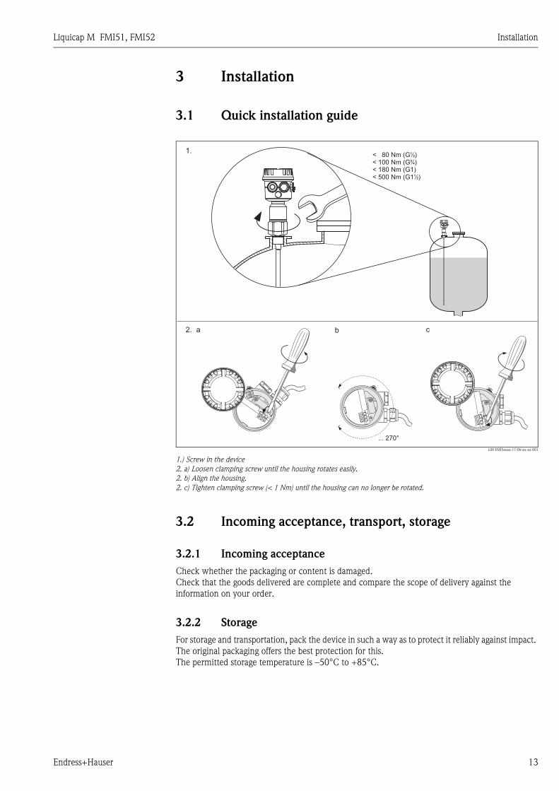
3.1 Quick installation guide
L00-FMI5xxxx-17-06-xx-xx-001
1.) Screw in the device
2. a) Loosen clamping screw until the housing rotates easily.
2. b) Align the housing.
2. c) Tighten clamping screw (< 1 Nm) until the housing can no longer be rotated.
3.2 Incoming acceptance, transport, storage
3.2.1 Incoming acceptance
Check whether the packaging or content is damaged.
Check that the goods delivered are complete and compare the scope of delivery against the
information on your order.
3.2.2 Storage
For storage and transportation, pack the device in such a way as to protect it reliably against impact.
The original packaging offers the best protection for this.
The permitted storage temperature is –50°C to +85°C.
12
a2.
1.
... 270°
b
12
c
12
< 80 Nm (G )< 100 Nm (G )< 180 Nm (G1)< 500 Nm (G1 )
½
¾
½
Installation Liquicap M FMI51, FMI52
14 Endress+Hauser
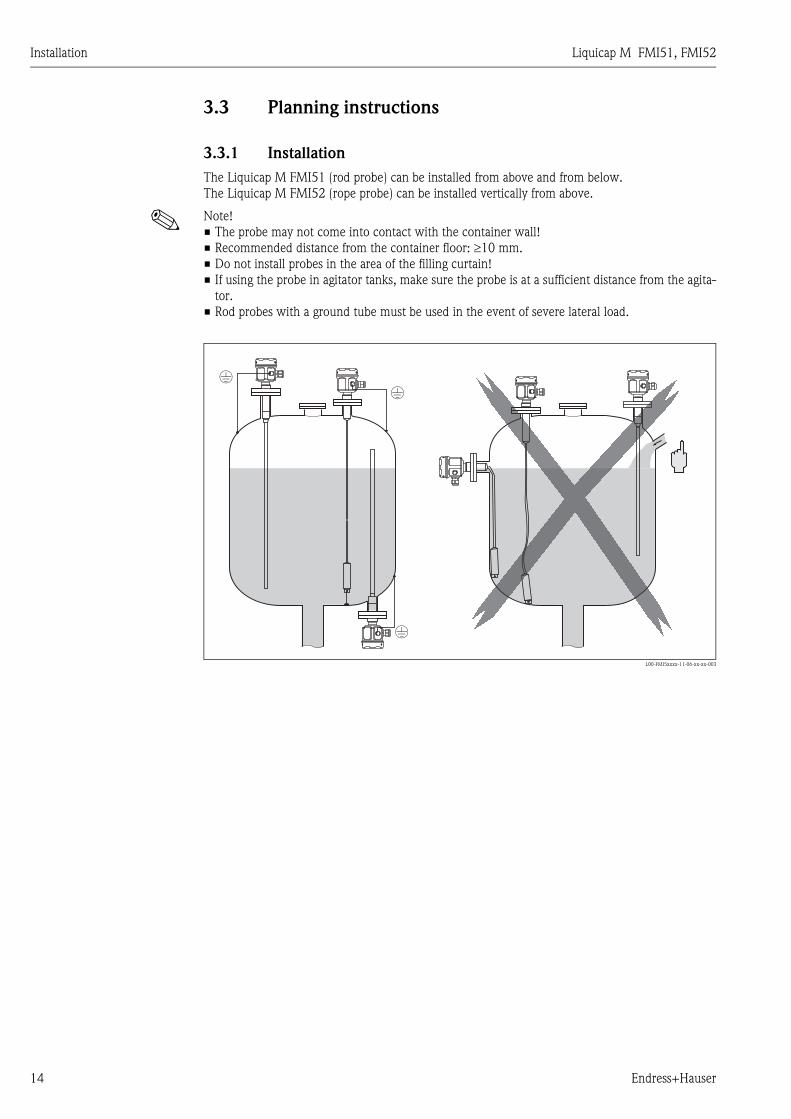
3.3 Planning instructions
3.3.1 Installation
The Liquicap M FMI51 (rod probe) can be installed from above and from below.
The Liquicap M FMI52 (rope probe) can be installed vertically from above.
! Note!
• The probe may not come into contact with the container wall!
• Recommended distance from the container floor: ≥10 mm.
• Do not install probes in the area of the filling curtain!
• If using the probe in agitator tanks, make sure the probe is at a sufficient distance from the agita-
tor.
• Rod probes with a ground tube must be used in the event of severe lateral load.
L00-FMI5xxxx-11-06-xx-xx-003

Liquicap M FMI51, FMI52 Installation
Endress+Hauser 15
3.3.2 Support with marine approval (GL)
Conductive or nonconductive support can be provided for fully insulated rod probes.
Partially insulated rod probes may only be supported with insulation at the uninsulated end of the
probe.
! Note!
• Rod probes with a diameter of 10 mm and 16 mm have to be supported with a length ≥ 1 m (see
drawing).
L00-FMI5xxxx-06-05-xx-xx-077
Example for calculating distances:
Probe length L = 2000 mm.
L/4 = 500 mm
L/2 = 1000 mm
Measured from the end of the probe rod = 300 mm.
3.4 Measuring condition
L/
4
L/
2
L
30
0m
m
• Measuring range L1 possible from the tip of
the probe to the process connection.
• Particularly suited for small containers.
• Use a ground tube for nonconductive
media.
Note!
When installing in a nozzle, use inactive
length (L3).
The 0 %, 100 % calibration can be inverted.
L00-FMI5xxxx-15-05-xx-xx-002
100 %
0 %
L3
L1

Installation Liquicap M FMI51, FMI52
16 Endress+Hauser
3.5 Minimum probe length for nonconductive media
(<1μs/cm)
lmin = ΔCmin / (Cs * [εr - 1])
3.6 Installation examples
3.6.1 Rod probes
Conductive tanks (metal tanks)
If the process connection of the probe is insulated from the metal tank (e.g. using seal material), the
ground connection on the probe housing must be connected to the tank using a short line.
! Note!
• A fully insulated rod probe may be neither shortened nor extended.
• If the insulation of the probe rod is damaged, this results in an incorrect measurement result.
• These application examples show vertical installation for continuous level measurement.
FMI51: rod probe
L00-FMI5xxxx-11-06-xx-xx-004
lmin = Minimum probe length
ΔCmin = 5 pF
Cs = Probe capacitance in air (see also → ä 89, "Additional capacitance")
εr = Dielectric constant e.g. oil = 2.0

Liquicap M FMI51, FMI52 Installation
Endress+Hauser 17
FMI51: rod probe with ground tube
Nonconductive tanks (plastic tanks)
When installing in a plastic tank, a probe with a ground tube must be used.
L00-FMI5xxxx-11-06-xx-xx-005
FMI51: rod probe with inactive length (e.g. for insulated tanks)
L00-FMI5xxxx-11-06-xx-xx-006

Installation Liquicap M FMI51, FMI52
18 Endress+Hauser
FMI51: rod probe with ground tube and inactive length (for mounting nozzles)
L00-FMI5xxxx-11-06-xx-xx-007
FMI51: fully insulated probe with clad flange for aggressive media
L00-FMI5xxxx-11-06-xx-xx-011

Liquicap M FMI51, FMI52 Installation
Endress+Hauser 19
3.6.2 Rope probes
! Note!
These application examples show the installation of rope probes for continuous level measurement.
FMI52: rope probe
L00-FMI5xxxx-11-06-xx-xx-008
FMI52: rope probe with inactive length (e.g. for insulated tanks)
L00-FMI5xxxx-11-06-xx-xx-009
Installation Liquicap M FMI51, FMI52
20 Endress+Hauser
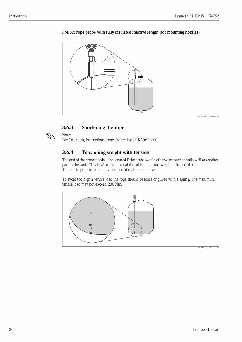
FMI52: rope probe with fully insulated inactive length (for mounting nozzles)
L00-FMI5xxxx-11-06-xx-xx-010
3.6.3 Shortening the rope
! Note!
See Operating Instructions, rope shortening kit KA061F/00.
3.6.4 Tensioning weight with tension
The end of the probe needs to be secured if the probe would otherwise touch the silo wall or another
part in the tank. This is what the internal thread in the probe weight is intended for.
The bracing can be conductive or insulating to the tank wall.
To avoid too high a tensile load the rope should be loose or guyed with a spring. The maximum
tensile load may not exceed 200 Nm.
L00-FMI5xxxx-11-06-xx-xx-012
Liquicap M FMI51, FMI52 Installation
Endress+Hauser 21
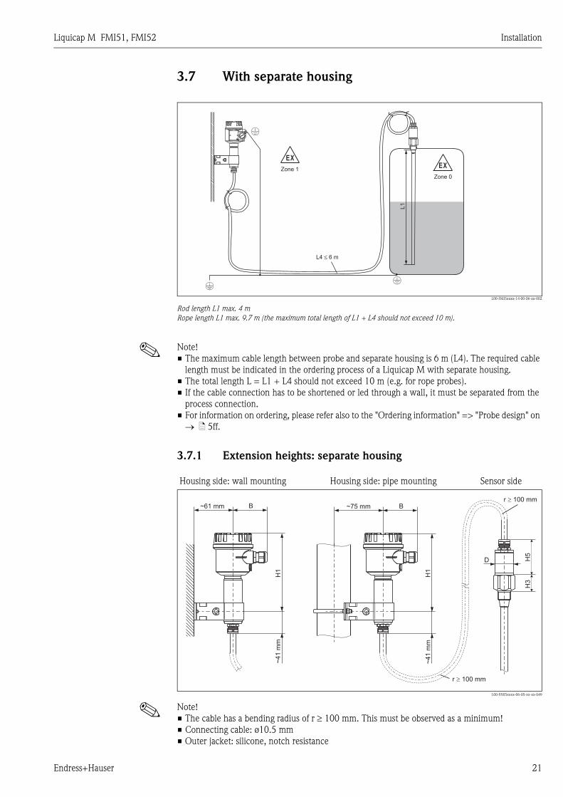
3.7 With separate housing
L00-FMI5xxxx-14-00-06-xx-002
Rod length L1 max. 4 m
Rope length L1 max. 9.7 m (the maximum total length of L1 + L4 should not exceed 10 m).
! Note!
• The maximum cable length between probe and separate housing is 6 m (L4). The required cable
length must be indicated in the ordering process of a Liquicap M with separate housing.
• The total length L = L1 + L4 should not exceed 10 m (e.g. for rope probes).
• If the cable connection has to be shortened or led through a wall, it must be separated from the
process connection.
• For information on ordering, please refer also to the "Ordering information" => "Probe design" on
→ ä 5ff.
3.7.1 Extension heights: separate housing
! Note!
• The cable has a bending radius of r ≥ 100 mm. This must be observed as a minimum!
• Connecting cable: ø10.5 mm
• Outer jacket: silicone, notch resistance
EX
Zone 1
L4 6 m≤
EX
Zone 0
L1
Housing side: wall mounting Housing side: pipe mounting Sensor side
L00-FMI5xxxx-06-05-xx-xx-049
~61 mm ~75 mm
~4
1m
m
~4
1m
m
BB
H3
H1
H1
H5
D
r 100 mm�
r 100 mm�
Installation Liquicap M FMI51, FMI52
22 Endress+Hauser
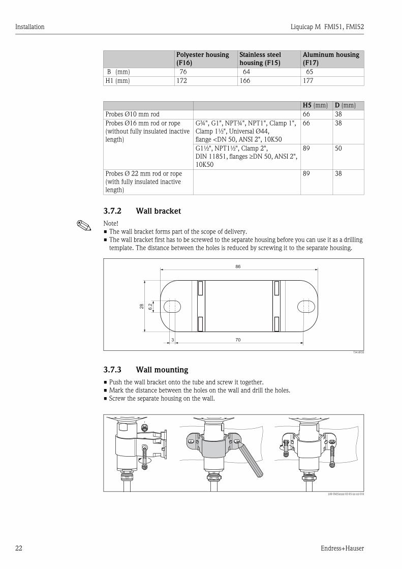
3.7.2 Wall bracket
! Note!
• The wall bracket forms part of the scope of delivery.
• The wall bracket first has to be screwed to the separate housing before you can use it as a drilling
template. The distance between the holes is reduced by screwing it to the separate housing.
TI418F20
3.7.3 Wall mounting
• Push the wall bracket onto the tube and screw it together.
• Mark the distance between the holes on the wall and drill the holes.
• Screw the separate housing on the wall.
L00-FMI5xxxx-03-05-xx-xx-010
Polyester housing
(F16)
Stainless steel
housing (F15)
Aluminum housing
(F17)
B (mm) 76 64 65
H1 (mm) 172 166 177
H5 (mm) D (mm)
Probes Ø10 mm rod 66 38
Probes Ø16 mm rod or rope
(without fully insulated inactive
length)
G¾", G1", NPT¾", NPT1", Clamp 1",
Clamp 1½", Universal Ø44,
flange <DN 50, ANSI 2", 10K50
66 38
G1½", NPT1½", Clamp 2",
DIN 11851, flanges ≥DN 50, ANSI 2",
10K50
89 50
Probes Ø 22 mm rod or rope
(with fully insulated inactive
length)
89 38
3
28
70
86
6.2
Liquicap M FMI51, FMI52 Installation
Endress+Hauser 23
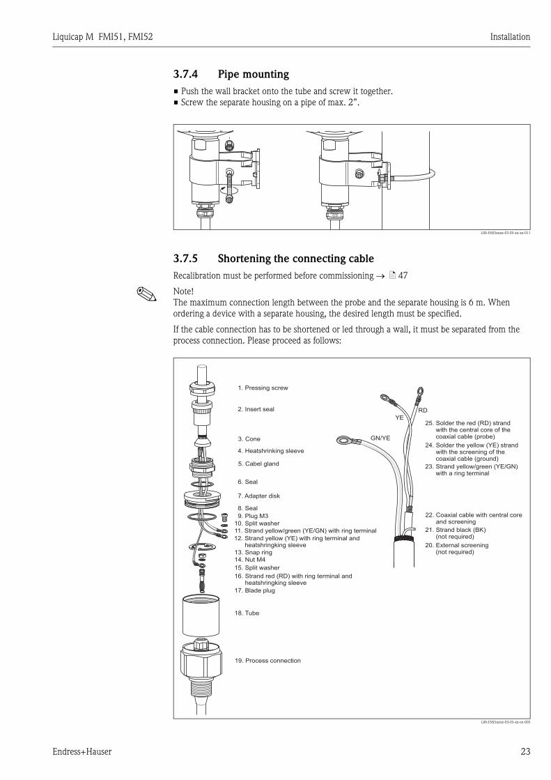
3.7.4 Pipe mounting
• Push the wall bracket onto the tube and screw it together.
• Screw the separate housing on a pipe of max. 2”.
L00-FMI5xxxx-03-05-xx-xx-011
3.7.5 Shortening the connecting cable
Recalibration must be performed before commissioning → ä 47
! Note!
The maximum connection length between the probe and the separate housing is 6 m. When
ordering a device with a separate housing, the desired length must be specified.
If the cable connection has to be shortened or led through a wall, it must be separated from the
process connection. Please proceed as follows:
L00-FMI5xxxx-03-05-xx-en-005
GN/YE
YE
RD
1. Pressing screw
2. Insert seal
5. Cabel gland
4. Heatshrinking sleeve
6. Seal
7. Adapter disk
8. Seal
9. Plug M3
10. Split washer
11. Strand yellow/green (YE/GN) with ring terminal
12. Strand yellow (YE) with ring terminal andheatshringking sleeve
13. Snap ring
14. Nut M4
15. Split washer
16. Strand red (RD) with ring terminal andheatshringking sleeve
17. Blade plug
18. Tube
19. Process connection
21. Strand black (BK)(not required)
23. Strand yellow/green (YE/GN)with a ring terminal
25. Solder the strandwith the central core of thecoaxial cable (probe)
red (RD)
24. Solder the strandwith the screening of the
yellow (YE)
coaxial cable (ground)
20. External screening(not required)
22. Coaxial cable withnd
central corea screening
3. Cone
Installation Liquicap M FMI51, FMI52
24 Endress+Hauser
• Loosen the pressing screw (1) with an open-end wrench (AF22). If necessary, hold the process
connection. Please make sure that neither the connecting cable nor the probe is turning with the
pressing screw.
• Pull the insert seal (2) out of the cable gland (5).
• Using an open-end wrench (AF22), disconnect the cable gland (5) from the adapter disk. If
necessary, hold it against the adapter disk (7) using an open-end wrench AF34.
• Loosen the adapter disk (7) from the tube (18).
• Remove the snap ring (13) with a pair of snap ring pliers.
• Clutch the nut (M4) of the blade plug with a pair of pliers and pull this out.
! Note!
• If you are shortening the connecting cable, we recommend to reuse all strands with ring
terminals.
• If the strands are not to be reused, the crimp connections of the new ring terminals fitted must
be isolated with a heat shrinking sleeve (risk of short-circuiting).
• All soldered joints must be insulated. Use heat-shrink tubes to do so.
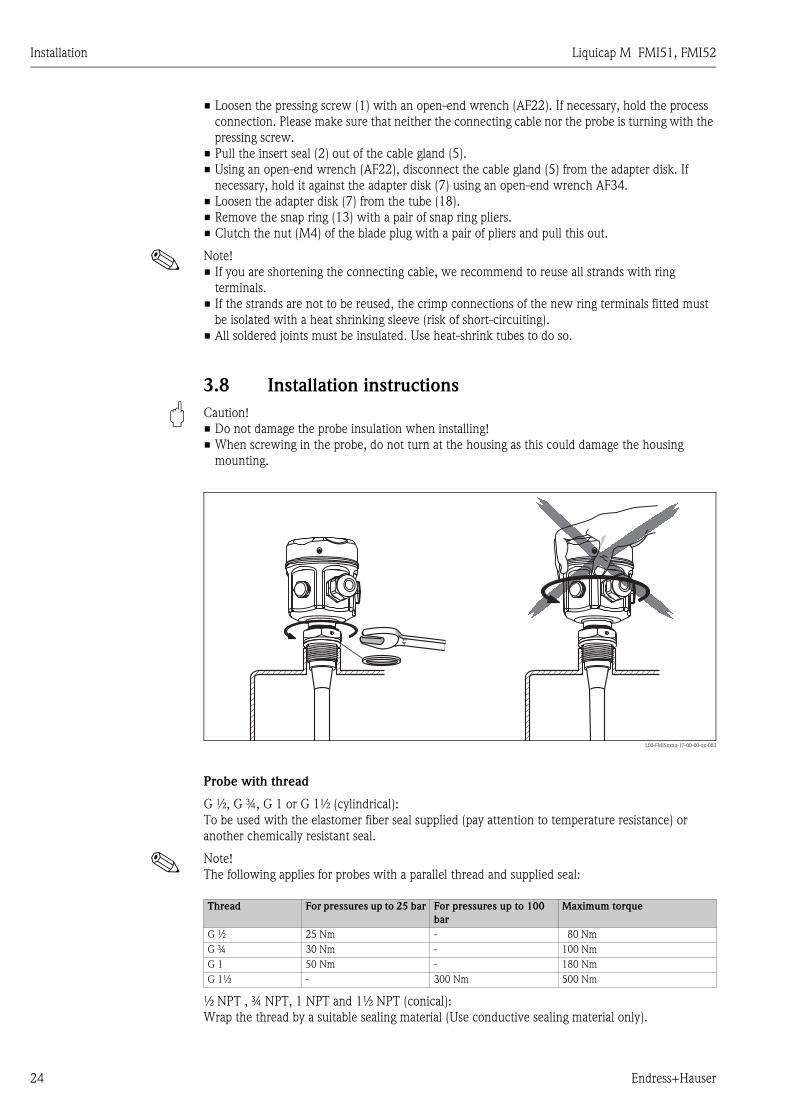
3.8 Installation instructions
" Caution!
• Do not damage the probe insulation when installing!
• When screwing in the probe, do not turn at the housing as this could damage the housing
mounting.
L00-FMI5xxxx-17-00-00-xx-003
Probe with thread
G ½, G ¾, G 1 or G 1½ (cylindrical):
To be used with the elastomer fiber seal supplied (pay attention to temperature resistance) or
another chemically resistant seal.
! Note!
The following applies for probes with a parallel thread and supplied seal:
½ NPT , ¾ NPT, 1 NPT and 1½ NPT (conical):
Wrap the thread by a suitable sealing material (Use conductive sealing material only).
4411
Thread For pressures up to 25 bar For pressures up to 100
bar
Maximum torque
G ½ 25 Nm - 80 Nm
G ¾ 30 Nm - 100 Nm
G 1 50 Nm - 180 Nm
G 1½ - 300 Nm 500 Nm

Liquicap M FMI51, FMI52 Installation
Endress+Hauser 25
Probe with Tri-Clamp, sanitary connection or flange
• The process seal must meet the specifications of the application (resistant to temperature and
medium).
• If the flange is PTFE-clad, this generally suffices as the seal up to the permitted operating pressure.
Probe with PTFE-clad flange
! Note!
Use spring washers (1).
It is recommended to retighten the flange bolts periodically, depending on process temperature and
pressure. Recommended torque: 60 to 100 Nm.
L00-FMI5xxxx-17-00-00-en-005
3.8.1 Aligning the housing
The housing can be rotated 270° to align the cable entry.
For an even better way of preventing moisture penetration, we recommend you route the
connecting cable downwards before the cable gland and secure it with a cable tie. This is particularly
recommended when mounting outdoors.
Housing (type F16, F15, F17, F13, T13)
• Unscrew cover
• Loosen Phillips screw at bottom of housing by turning the screw 3 to 4 times
• Turn the housing to the desired position (max. 270°, from one stop to the next)
• Tighten Phillips screw at bottom of housing.
! Note!
For housing type T13 with a separate connection compartment, the Phillips screw for aligning the
housing is also located in the electronics compartment.
1
spring washers

Installation Liquicap M FMI51, FMI52
26 Endress+Hauser
L00-FMI5xxxx-04-00-00-xx-002
1. Loosen clamping screw until the housing rotates easily.
2. Align the housing.
3. Tighten clamping screw (< 1 Nm) until the housing can no longer be rotated.
4. Additional protection against moisture penetration for electronics compartment.
3.8.2 Sealing the probe housing
No water should enter the device when performing installation, connection and configuration tasks.
Always seal the housing cover and cable entries securely.
The O-ring seal on the housing cover is shipped with a coat of special lubricant applied. In this way,
the cover can be sealed tight and the aluminum thread does not bite when screwing down.
Never use mineral oil-based grease as this destroys the O-ring.
3.9 Post-installation check
After installing the measuring device, carry out the following checks:
• Is the device damaged (visual inspection)?
• Does the device meet the specifications at the measuring point with regard to process tempera-
ture/pressure, ambient temperature, measuring range etc.?
• Has the process connection been tightened with the appropriate tightening torque?
• Are the measuring point number and labeling correct (visual inspection)?
• Is the device adequately protected against precipitation and direct sunshine?
3.9.1 Measuring range with FEI50H (HART)
• Measuring frequency: 500 kHz
• Span: ΔC = 25 to 4000 pF recommended (2 to 4000 pF possible)
• Final capacitance: CE = max. 4000 pF
• Adjustable initial capacitance:
– CA = 0 to 2000 pF (< 6 m probe length)
12
1.
... 270°
2.
12
3.
12
4.

Liquicap M FMI51, FMI52 Wiring
Endress+Hauser 27
– CA = 0 to 4000 pF (> 6 m probe length)
4 Wiring
" Caution!
Before connecting the supply voltage, note the following:
• The supply voltage must match the data specified on the nameplate (1).
• Switch off the supply voltage before connecting the device.
• Connect the potential equalization to the ground terminal on the sensor.
! Note!
• When using the probe in hazardous areas, the relevant national standards and the information in
the safety instructions (XA) must be observed.
• Use the specified cable gland only.
4.1 Recommendations for connection
4.1.1 Potential equalization
" Caution!
In Ex-applications, the screen may only be grounded on the sensor side.
Connect the potential equalization to the outer ground terminal of the housing (T13, F13, F16, F17,
F27). In the case of the stainless steel housing F15, the ground terminal (depending on the version)
can also be located in the housing.
For further safety instructions, please refer to the separate documentation for applications in
hazardous areas.
4.1.2 Electromagnetic compatibility (EMC)
Interference emission to EN 61326, Electrical Equipment Class B. Interference immunity to EN
61326, Annex A (Industrial) and NAMUR Recommendation NE 21 (EMC).
4.1.3 Cable specification
The electronic inserts can be connected using commercially available instrument cables.
When using shielded instrument cables, it is recommended to connect the shielding on both sides
to optimize the shielding effect (if potential equalization is present).
L00-FTI5xxxx-04-05-xx-xx-011
* Cable entries
Nickel-plated brass: ∅d = 7 to 10.5 mm (0.28 to 0.41 in)
Synthetic material: ∅d = 5 to 10 mm (0.2 to 0.38 in)
Stainless steel: ∅d = 7 to 12 mm (0.28 to 0.47 in)
max. 2.5 mm²
3 mm(1/8 in)
(max. AWG 14)
max. 4 mm²
(max. AWG 12)
FEI..
ød
M20x1.5 *
Wiring Liquicap M FMI51, FMI52
28 Endress+Hauser
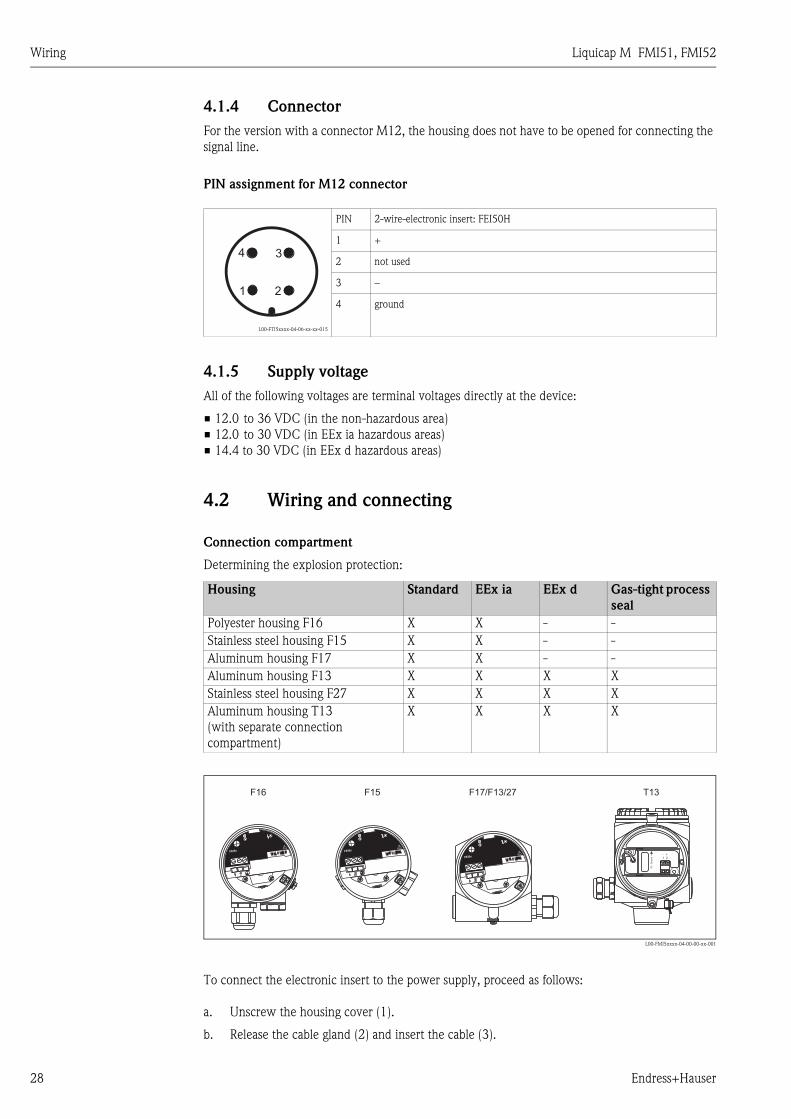
4.1.4 Connector
For the version with a connector M12, the housing does not have to be opened for connecting the
signal line.
PIN assignment for M12 connector
4.1.5 Supply voltage
All of the following voltages are terminal voltages directly at the device:
• 12.0 to 36 VDC (in the non-hazardous area)
• 12.0 to 30 VDC (in EEx ia hazardous areas)
• 14.4 to 30 VDC (in EEx d hazardous areas)
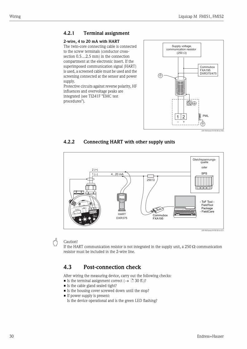
4.2 Wiring and connecting
Connection compartment
Determining the explosion protection:
L00-FMI5xxxx-04-00-00-xx-001
To connect the electronic insert to the power supply, proceed as follows:
a. Unscrew the housing cover (1).
b. Release the cable gland (2) and insert the cable (3).
L00-FTI5xxxx-04-06-xx-xx-015
PIN 2-wire-electronic insert: FEI50H
1 +
2 not used
3 –
4 ground
Housing Standard EEx ia EEx d Gas-tight process
seal
Polyester housing F16 X X - -
Stainless steel housing F15 X X - -
Aluminum housing F17 X X - -
Aluminum housing F13 X X X X
Stainless steel housing F27 X X X X
Aluminum housing T13
(with separate connection
compartment)
X X X X
21
34
– +
FEI5x4...20 mA
1 2+ –
– +
T13F15F16 F17/F13/27
IS-
Gro
un
d
– +1 2
FEI5x
FEI5x
FEI5x

Liquicap M FMI51, FMI52 Wiring
Endress+Hauser 29
L00-FTI5xxxx-04-06-xx-xx-003
L00-FTI5xxxx-04-06-xx-xx-004
Information on connecting shielded cables is provided in TI241 "EMC test procedures".
1
a. b.
2
3
– +
FEI55
8/16mA
11...36V DC– +
7 3
I=16mA
5
1 2
IS-
Gro
un
d
– +
1 2
a. + b.
IS-
Gro
und
– +
1 22
3
1
1 2
Wiring Liquicap M FMI51, FMI52
30 Endress+Hauser
4.2.1 Terminal assignment
4.2.2 Connecting HART with other supply units
L00-FMI5xxxx-04-00-00-en-015
" Caution!
If the HART communication resistor is not integrated in the supply unit, a 250 Ω communication
resistor must be included in the 2-wire line.
4.3 Post-connection check
After wiring the measuring device, carry out the following checks:
• Is the terminal assignment correct (→ ä 30 ff.)?
• Is the cable gland sealed tight?
• Is the housing cover screwed down until the stop?
• If power supply is present:
Is the device operational and is the green LED flashing?
2-wire, 4 to 20 mA with HART
The twin-core connecting cable is connected
to the screw terminals (conductor cross-
section 0.5…2.5 mm) in the connection
compartment at the electronic insert. If the
superimposed communication signal (HART)
is used, a screened cable must be used and the
screening connected at the sensor and power
supply.
Protective circuits against reverse polarity, HF
influences and overvoltage peaks are
integrated (see TI241F "EMC test
procedures").
L00-FMI5xxxx-04-00-00-en-002
1 2– +
CommuboxFXA195DXR375/475
PML
Supply voltage,communication resistor
(250 )�
2 (+)
1 (–)
HART
DXR375
1# % &
Copy
G H I
P Q R S
, ( ) ‘
A B C
Paste
PageOn
PageUp
DeleteBksp
Insert
J K L
T U V
_ < >
D E F
Hot Key
+ Hot Key
M N O
W X Y Z
+ * /
4
7
.
2
5
8
0
375FIELD COMMUNICATOR
3
6
9
-
9 6
FMP40: LIC0001ONLINE
1 GROUP SELECT2 PV 8.7 m
HELP SAVE
dsdmdmdf das.asdas faasas la.
- ToF Tool -FieldToolPackage
- FieldCare
CommuboxFXA195
250 Ώ
4...20 mA
-+
FEI50H
4...20mA-
+
+-Display
1
73
5
Gleichspannungs-quelle
oder
SPS
Liquicap M FMI51, FMI52 Operation
Endress+Hauser 31
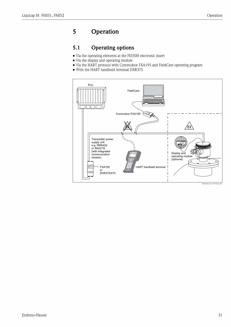
5 Operation
5.1 Operating options
• Via the operating elements at the FEI50H electronic insert
• Via the display and operating module
• Via the HART protocol with Commubox FXA195 and FieldCare operating program
• With the HART handheld terminal DXR375
L00-FMI5xxxx-14-00-06-en-001
ENDRESS + HAUSERRMA 422
1# % &
Copy
G H I
P Q R S
, ( ) ‘
A B C
Paste
PageOn
PageUp
DeleteBksp
Insert
J K L
T U V
_ < >
D E F
Hot Key
+ Hot Key
M N O
W X Y Z
+ * /
4
7
.
2
5
8
0
375FIELD COMMUNICATOR
3
6
9
-
9 6
DELTABAR: * * * * * * * *ONLINE
1 QUICK SETUP2 OPERATING MENU
4 SV 0 °C3 PV 352 mbar
HELP SAVE
dsdmdmdf das.
asdas faasas la.
EXEX
64.50 %
+ �
Measured Value
FieldCare
Commubox FXA195
HART handheld terminal
PLC
Displayperating
ando module(optional)
64.50 %
+ �
Measured Value
FXA195orDXR375/475
Transmitter powersupply unite.g. RMA422or RN221N(with integratedcommunicationresistor)

Operation Liquicap M FMI51, FMI52
32 Endress+Hauser
5.1.1 Display and operating elements at the FEI50H electronic insert
L00-FMI5xxxx-07-05-xx-en-100
Green LED ( indicates operation):
• Flashes every 5 s:
– Indicates whether the device is operational.
• Flashes once every s:
– The device is in the calibration mode
Red LED ( indicates a fault or malfunction):
• Flashes five times a s:
– Capacitance at probe is too large, short-circuit at the probe or FEI50H is defective
• Flashes once every s:
– The temperature in the electronic insert is outside the permitted temperature range.
Key (–)
• To execute the functions set via the function switch
Key (+)
• To execute the functions set via the function switch
Function switch
• 1 : Operation
– Switch position for normal operation
• 2 : Empty calibration
– Empty calibration is carried out in this operating mode.
• 3 : Full calibration
– Full calibration is carried out in this operating mode.
• 4 : Measuring modes
– In this operating mode, chose between operation for media that form buildup
(e.g. yoghurt) or for media without buildup (e.g. water).
• 5 : Measuring range
– In this operating mode, select the measuring range in pF for:
=> Measuring range probe length < 6 m (corresponds to 2000 pF)
=> Measuring range probe length > 6 m (corresponds to 4000 pF)
• 6 : Self-test
– In this operating mode, you can activate the self-test.
4.0 mA
V~V=
A
- +
FEI50H4...20mA - +
+ -Display
1
7 3
5
Red LEDGreen LED
Function switch
Current pick-off4...20 mA
+ Key– Key
Liquicap M FMI51, FMI52 Operation
Endress+Hauser 33
• 7 : Reset (factory settings)
– In this operating mode, you can restore the data of the factory settings.
• 8 : Upload sensor DAT (EEPROM)
– In this operating mode, you can:
=> Transfer the calibration values in the electronic insert to the sensor DAT (EEPROM) if
replacing
the probe
=> Transfer the calibration values of the sensor DAT (EEPROM) to the electronics if replacing
the
electronic insert
Display connection
• For onsite display and operation (optional)
– Display and operating module
4 to 20 mA current pick-off
• E.g. for full/empty calibration with multimeter .
(No need to disconnect circuit!)
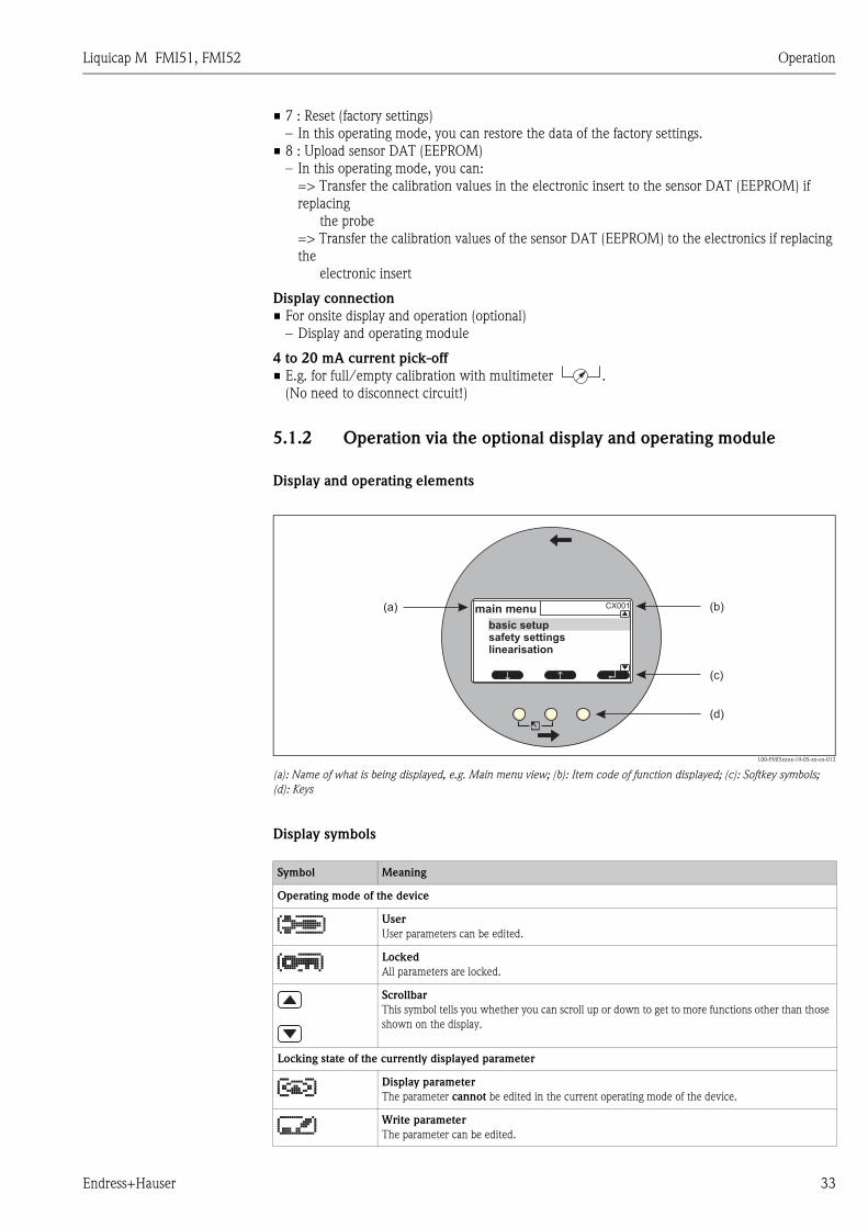
5.1.2 Operation via the optional display and operating module
Display and operating elements
L00-FMI5xxxx-19-05-xx-en-012
(a): Name of what is being displayed, e.g. Main menu view; (b): Item code of function displayed; (c): Softkey symbols;
(d): Keys
Display symbols
(d)
(c)
(a) (b)
↵↑↑
CX001main menu
basic setupsafety settingslinearisation
Symbol Meaning
Operating mode of the device
User
User parameters can be edited.
Locked
All parameters are locked.
Scrollbar
This symbol tells you whether you can scroll up or down to get to more functions other than those
shown on the display.
Locking state of the currently displayed parameter
Display parameter
The parameter cannot be edited in the current operating mode of the device.
Write parameter
The parameter can be edited.
Operation Liquicap M FMI51, FMI52
34 Endress+Hauser
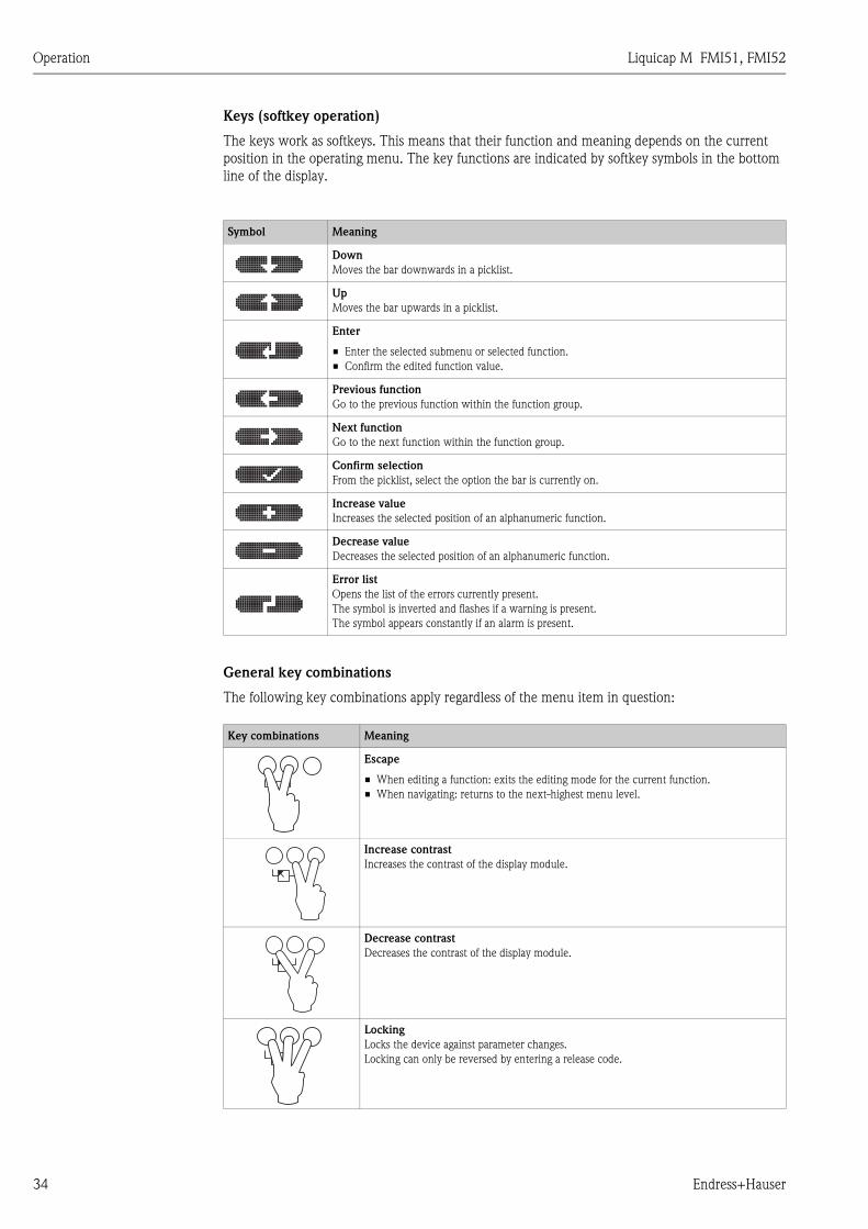
Keys (softkey operation)
The keys work as softkeys. This means that their function and meaning depends on the current
position in the operating menu. The key functions are indicated by softkey symbols in the bottom
line of the display.
General key combinations
The following key combinations apply regardless of the menu item in question:
Symbol Meaning
Down
Moves the bar downwards in a picklist.
Up
Moves the bar upwards in a picklist.
Enter
• Enter the selected submenu or selected function.
• Confirm the edited function value.
Previous function
Go to the previous function within the function group.
Next function
Go to the next function within the function group.
Confirm selection
From the picklist, select the option the bar is currently on.
Increase value
Increases the selected position of an alphanumeric function.
Decrease value
Decreases the selected position of an alphanumeric function.
Error list
Opens the list of the errors currently present.
The symbol is inverted and flashes if a warning is present.
The symbol appears constantly if an alarm is present.
Key combinations Meaning
Escape
• When editing a function: exits the editing mode for the current function.
• When navigating: returns to the next-highest menu level.
Increase contrast
Increases the contrast of the display module.
Decrease contrast
Decreases the contrast of the display module.
Locking
Locks the device against parameter changes.
Locking can only be reversed by entering a release code.
Liquicap M FMI51, FMI52 Operation
Endress+Hauser 35
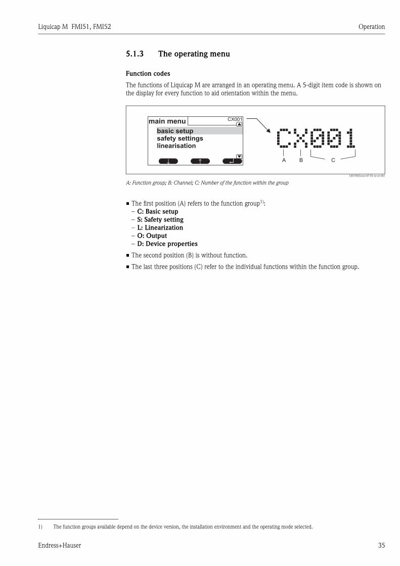
5.1.3 The operating menu
Function codes
The functions of Liquicap M are arranged in an operating menu. A 5-digit item code is shown on
the display for every function to aid orientation within the menu.
L00-FMI5xxxx-07-05-xx-en-001
A: Function group; B: Channel; C: Number of the function within the group
• The first position (A) refers to the function group1):
– C: Basic setup
– S: Safety setting
– L: Linearization
– O: Output
– D: Device properties
• The second position (B) is without function.
• The last three positions (C) refer to the individual functions within the function group.
CBA
�����↵↑
↑
CX001main menu
basic setupsafety settingslinearisation
1) The function groups available depend on the device version, the installation environment and the operating mode selected.
Operation Liquicap M FMI51, FMI52
36 Endress+Hauser
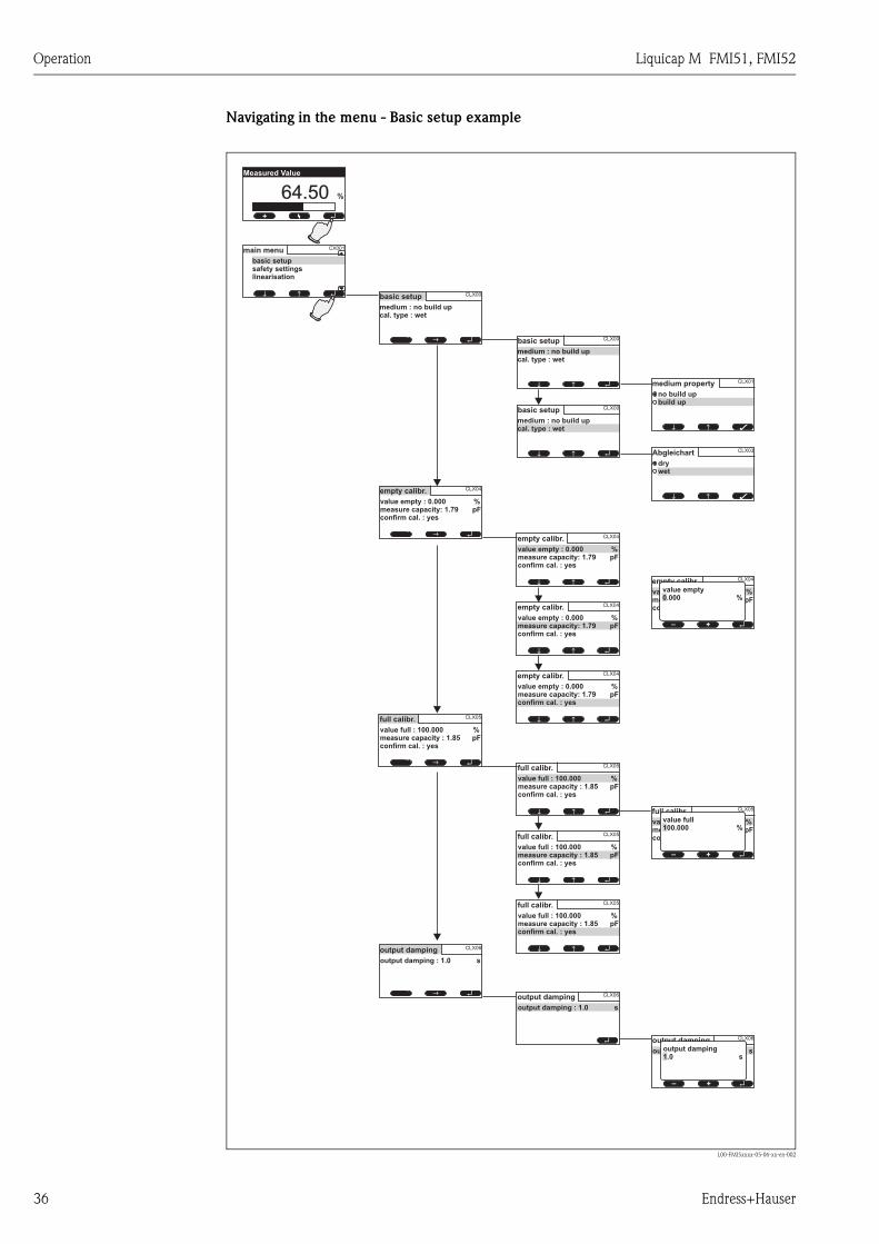
Navigating in the menu - Basic setup example
L00-FMI5xxxx-05-06-xx-en-002
64.50 %
+ ↵
Measured Value
↵↑↑
CX001main menu
basic setupsafety settingslinearisation
↵↑ ↑
CLX05
value full : 100.000 %measure capacity : 1.85 pFconfirm cal. : yes
full calibr.
↵
CLX00basic setup
medium : no build upcal. type : wet
↑↑
↵
CLX00basic setup
medium : no build upcal. type : wet
↑↑
↵
CLX05
value full : 100.000 %measure capacity : 1.85 pFconfirm cal. : yes
full calibr.
↑↑
↵
CLX05
value full : 100.000 %measure capacity : 1.85 pFconfirm cal. : yes
full calibr.
↑↑
↵
CLX05
value full : 100.000 %measure capacity : 1.85 pFconfirm cal. : yes
full calibr.
↑↑
CLX01medium property
no build upbuild up
↑↑ Â
CLX03Abgleichart
drywet
↑↑ Â
↵↑ ↑
CLX04
value empty : 0.000 %measure capacity: 1.79 pFconfirm cal. : yes
empty calibr.
↑↑ ↵
CLX04
value empty : 0.000 %measure capacity: 1.79 pFconfirm cal. : yes
empty calibr.
↑↑ ↵
CLX04
value empty : 0.000 %measure capacity: 1.79 pFconfirm cal. : yes
empty calibr.
↑↑ ↵
CLX04
value empty : 0.000 %measure capacity: 1.79 pFconfirm cal. : yes
empty calibr.
↵
CLX04
value empty : 0.000 %measure capacity: 1.79 pFconfirm cal. : yes
empty calibr.
+–
↵
CLX05
value full : 100.000 %measure capacity : 1.85 pFconfirm cal. : yes
full calibr.
+–
↵↑ ↑
CLX00basic setup
medium : no build upcal. type : wet
↵
CLX06
output damping : 1.0 s
output damping↵↑ ↑
CLX06
output damping : 1.0 s
output damping
CLX06
output damping : 1.0 s
output damping
↵+–
value empty0.000 %
value full100.000 %
output damping1.0 s

Liquicap M FMI51, FMI52 Operation
Endress+Hauser 37
Launching menus
! Note!
If you are within a submenu and do not press a key for 15 minutes, the display automatically
switches to the main screen (measured value).
Navigation always starts with the main screen (measured value display). From here, you can go to
the following menus with the aid of the keys:
L00-FMI5xxxx-19-05-xx-en-011
• Measured value
Displays the measured value in %, mA or pF.
• Main menu
The main menu contains all the parameters of Liquicap M. It is split into submenus. Some of the
submenus themselves have additional submenus.
An overview of the submenus and the functions they contain is provided in the "Commissioning"
section.
• Actual errors
If the automatic monitoring function of Liquicap M detects an error, the related softkey symbol
appears over the center key.
If the softkey symbol is flashing, only "Warning"-type errors are present2).
If the symbol is displayed continuously, at least one "Alarm"-type error is present2.
Once you press the key, a list appears with all the errors currently pending.
...
...
...
...
Warning 103
Alarm 101
main menu
actual error
basic setup
safety settings
64.50 %
+ ↵
Measured Value
22.000 mA
+ ↵
Measured Value
1040.00 pF
+ ↵
Measured Value
2) See Section 9.2, "System error messages" for information on the difference between a "Warning" and an "Alarm".
Operation Liquicap M FMI51, FMI52
38 Endress+Hauser
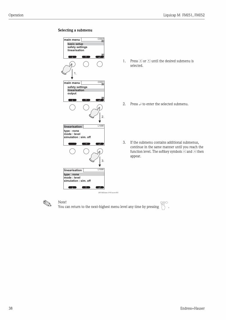
Selecting a submenu
! Note!
You can return to the next-highest menu level any time by pressing .
L00-FMI5xxxx-19-05-xx-en-001
1. Press W or V until the desired submenu is
selected.
2. Press ↵ to enter the selected submenu.
3. If the submenu contains additional submenus,
continue in the same manner until you reach the
function level. The softkey symbols U and T then
appear.
1.
2.
3.
↵↑↑
CX001main manu
safety settingslinearisationoutput
↵↑↑
CX001main menu
basic setupsafety settingslinearisation
↵↑ ↑
L1008linearisation
type : nonemode : levelsimulation : sim. off
L1008linearisation
type : nonemode : levelsimulation : sim. off
↵↑↑

Liquicap M FMI51, FMI52 Operation
Endress+Hauser 39
Selecting a function and subfunction
Once you have reached the function level, you can navigate through the functions with U and T.
The current values of all the related subfunctions are displayed. Proceed as follows to change a
value:
! Note!
You can leave the function at any time and return to the next-highest menu level by pressing .
L00-FMI5xxxx-19-05-xx-en-002
1. Press U or T until you reach the desired function.
2. Press ↵ to enter the selected function.
3. Use W and V to select the desired subfunction.
(This step is not necessary if the function only has
one subfunction.)
4. Press ↵ to enter the subfunction.
The editing process that follows depends on the
type of subfunction selected (picklist, numeric
function or alphanumeric function). Details are
explained in the following sections.
3.
1.
2.
4.
↵↑ ↑
CLX04
value empty : 0.000 %measure capacity: 1.79 pFconfirm cal. : yes
empty calibr.
↵↑ ↑
CLX00basic setup
medium : no build upcal. type : wet
↑↑ ↵
CLX18
value empty : 0.000 %measure capacity: 1.79 pFconfirm cal. : yes
empty calibr.
↑↑ ↵
CLX18
value empty : 0.000 %measure capacity: 1.79 pFconfirm cal. : yes
empty calibr.
Operation Liquicap M FMI51, FMI52
40 Endress+Hauser
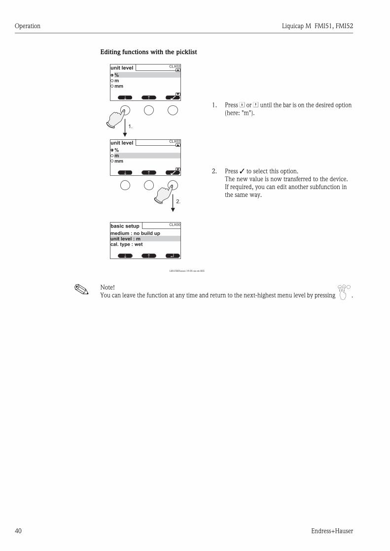
Editing functions with the picklist
! Note!
You can leave the function at any time and return to the next-highest menu level by pressing .
L00-FMI5xxxx-19-05-xx-en-003
1. Press W or V until the bar is on the desired option
(here: "m").
2. Press  to select this option.
The new value is now transferred to the device.
If required, you can edit another subfunction in
the same way.
1.
2.
↑↑ ↵
CLX00basic setup
medium : no build upunit level : mcal. type : wet
CLX02unit level
%mmm
↑↑ Â
CLX02unit level
%mmm
↑↑ Â
Liquicap M FMI51, FMI52 Operation
Endress+Hauser 41
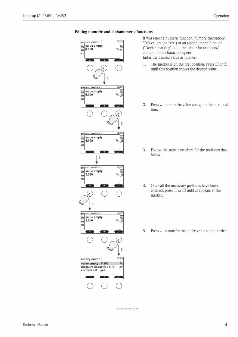
Editing numeric and alphanumeric functions
L00-FMI5xxxx-19-05-xx-en-004
If you select a numeric function ("Empty calibration",
"Full calibration" etc.) or an alphanumeric function
("Device marking" etc.), the editor for numbers/
alphanumeric characters opens.
Enter the desired value as follows:
1. The marker is on the first position. Press S or O
until this position shows the desired value.
2. Press ↵ to enter the value and go to the next posi-
tion.
3. Follow the same procedure for the positions that
follow.
4. Once all the necessary positions have been
entered, press S or O until ↵ appears at the
marker.
5. Press ↵ to transfer the entire value to the device.
4.
1.
2.
3.
5.
↵
CLX04
value empty : 0.000 %measure capacity : 1.79 pFconfirm cal. : yes
empty calibr.
+–
↵
CLX04
value empty : 0.000 %measure capacity : 1.79 pFconfirm cal. : yes
empty calibr.
+–
↵
CLX04
value empty : 0.000 %measure capacity : 1.79 pFconfirm cal. : yes
empty calibr.
+–
↵
CLX04
value empty : 0.000 %measure capacity : 1.79 pFconfirm cal. : yes
empty calibr.
+–
↵
CLX04
value empty : 0.000 %measure capacity : 1.79 pFconfirm cal. : yes
empty calibr.
+–
↑↑ ↵
CLX04
value empty : 5.500 %measure capacity : 1.79 pFconfirm cal. : yes
empty calibr.
value empty0.000 %
value empty5.000 %
value empty5.000 %
value empty5.500 %
value empty5.500 %↵
Operation Liquicap M FMI51, FMI52
42 Endress+Hauser
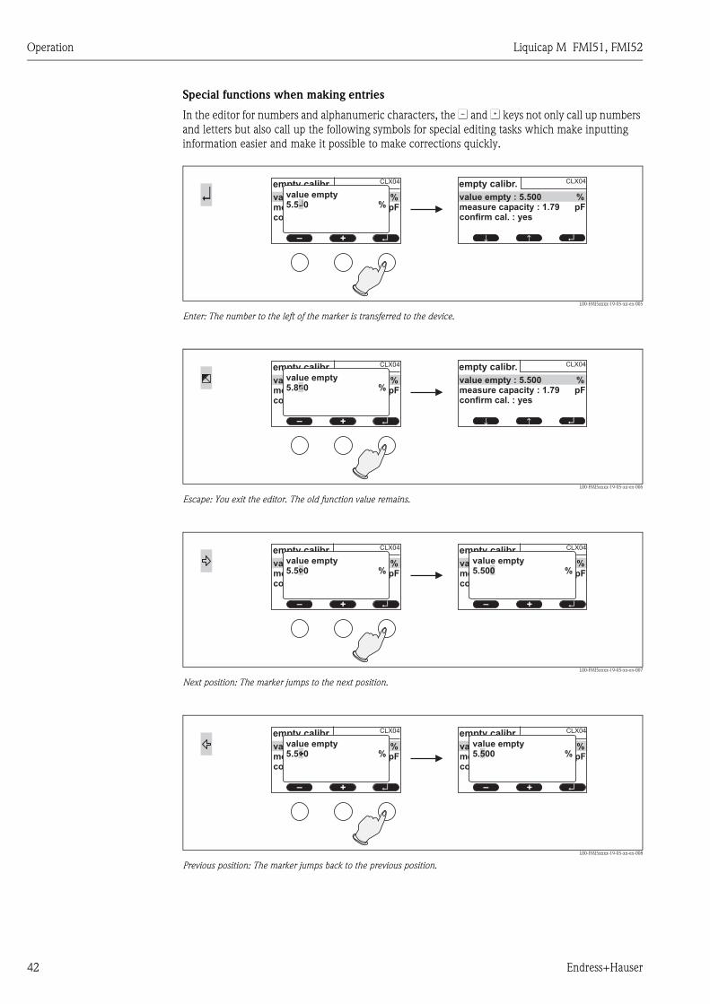
Special functions when making entries
In the editor for numbers and alphanumeric characters, the S and O keys not only call up numbers
and letters but also call up the following symbols for special editing tasks which make inputting
information easier and make it possible to make corrections quickly.
L00-FMI5xxxx-19-05-xx-en-005
Enter: The number to the left of the marker is transferred to the device.
L00-FMI5xxxx-19-05-xx-en-006
Escape: You exit the editor. The old function value remains.
L00-FMI5xxxx-19-05-xx-en-007
Next position: The marker jumps to the next position.
L00-FMI5xxxx-19-05-xx-en-008
Previous position: The marker jumps back to the previous position.
↵↑
↑ ↵
CLX04
value empty : 5.500 %measure capacity : 1.79 pFconfirm cal. : yes
empty calibr.
↵
CLX04
value empty : 0.000 %measure capacity : 1.79 pFconfirm cal. : yes
empty calibr.value empty5.500 %
+–
↵
↑↑ ↵
CLX04
value empty : 5.500 %measure capacity : 1.79 pFconfirm cal. : yes
empty calibr.
↵
CLX04
value empty : 0.000 %measure capacity : 1.79 pFconfirm cal. : yes
empty calibr.value empty5.800 %
+–
↵
CLX04
value empty : 0.000 %measure capacity : 1.79 pFconfirm cal. : yes
empty calibr.value empty5.500 %
+– ↵
CLX04
value empty : 0.000 %measure capacity : 1.79 pFconfirm cal. : yes
empty calibr.
+–
value empty5.500 %
↵
CLX04
value empty : 0.000 %measure capacity : 1.79 pFconfirm cal. : yes
empty calibr.value empty5.500 %
+– ↵
CLX04
value empty : 0.000 %measure capacity : 1.79 pFconfirm cal. : yes
empty calibr.
+–
value empty5.500 %

Liquicap M FMI51, FMI52 Operation
Endress+Hauser 43
L00-FMI5xxxx-19-05-xx-en-009
Delete: The current position and all positions to the right of this position are deleted.
Return to the measured value display
L00-FMI5xxxx-19-05-xx-en-010
Pressing the left and center key simultaneously has the following effect:
• Takes you from the editing mode to the display mode of the functions
• Takes you from the display mode of the functions to the submenu
• Takes you from the submenu to the main menu
• Takes you from the main menu to the measured value display.
5.2 Error messages
If the automatic monitoring function of Liquicap M detects an error, the related softkey symbol
appears over the center key.
If the softkey symbol is flashing, only "Warning"-type errors are present3).
If the symbol is displayed continuously, at least one "Alarm"-type error is present 3.
Once you press the key, a list appears with all the errors currently pending.
↵
CLX04
value empty : 0.000 %measure capacity : 1.79 pFconfirm cal. : yes
empty calibr.value empty5.500 %
+– ↵
CLX04
value empty : 0.000 %measure capacity : 1.79 pFconfirm cal. : yes
empty calibr.
+–
value empty5.5 %
. . .
↵
CLX00basic setup
medium : no build upunit level : %cal. type : wet
↑↑ ↵↑ ↑
CLX00basic setup
medium : no build upunit level : %cal. type : wet
CLX01medium property
no build upbuild up
↑↑ Â
3) See Section 9.2, "System error messages" for information on the difference between a "Warning" and an "Alarm".
Operation Liquicap M FMI51, FMI52
44 Endress+Hauser
5.3 Locking/unlocking configuration
5.3.1 Key locking
Press all three keys simultaneously. The device is then locked against entries.
5.3.2 Key unlocking
Press all three keys simultaneously. The device is then unlocked.
5.3.3 Software locking
Locking
Go to the "Safety settings" function.
In the menu, the current locking status of the device is displayed in the "Status" subfunction under
"Safety settings" (SAX01). The following values can appear:
• Unlocked
All parameters can be modified.
• Locked
The device has been locked by means of the operating menu. It can only be enabled again by
entering "100" in the "Safety settings" function.
If an attempt is made to change a parameter, the device goes to the "Safety settings" function. "Key
locking" is displayed in the "Status" subfunction. Press all the keys simultaneously. The device
then goes back to the original function and all the parameters can be changed again.
• Key locked
The device has been locked by means of the operating keys. It can only be enabled again by press-
ing all three keys simultaneously.
! Note!
A key symbol is shown on the display when locked.
5.4 Resetting to factory setting (reset)
" Caution!
The reset can affect the measurement as the current values are overwritten by those of the factory
calibration 0 % (4 mA) and 100 % (20 mA).
Using the reset
A reset is always recommended if a device with an unknown history is to be used.
Effects of a reset
• All parameters are reset to the factory setting.
• The linearization is reset to "linear". However, any linearization table available is retained and can
be activated again where necessary.
! Note!
The factory setting of the parameters is marked in bold in the menu overview (see the "Basic setup"
menu ff.).
Performing a reset
To carry out a reset, enter the value "333" in the "Device properties/Diagnosis/Password reset/
Reset" function.

Liquicap M FMI51, FMI52 Operation
Endress+Hauser 45
5.5 Operation via FieldCare Device Setup
5.5.1 FieldCare Device Setup - operating program
FieldCare is a graphic operating program for Endress+Hauser measuring devices based on the time-
of-flight principle. It is used to support commissioning, data back-up, signal analysis and
documentation of the devices. The following operating systems are supported:
Windows 2000, Windows XP, Windows Vista and Windows 7.
FieldCare supports the following functions:
• Configuration of transmitters in online operation
• Tank linearization
• Loading and saving device data (upload/download)
• Documentation of the measuring point
! Note!
Further information on FieldCare is provided on the CD-ROM which is supplied with the device.
Menu-guided commissioning
Basic setup2_de
Connection options:
• HART with Commubox 195
Operation Liquicap M FMI51, FMI52
46 Endress+Hauser
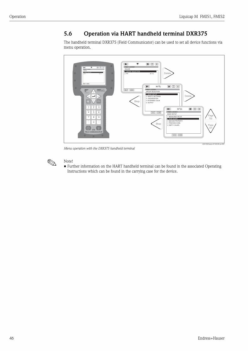
5.6 Operation via HART handheld terminal DXR375
The handheld terminal DXR375 (Field Communicator) can be used to set all device functions via
menu operation.
L00-FMI5xxxx-07-00-00-xx-007
Menu operation with the DXR375 handheld terminal
! Note!
• Further information on the HART handheld terminal can be found in the associated Operating
Instructions which can be found in the carrying case for the device.
1# % &
Copy
G H I
P Q R S
, ( ) ‘
A B C
Paste
PageOn
PageUp
DeleteBksp
Insert
J K L
T U V
_ < >
D E F
Hot Key
+ Hot Key
M N O
W X Y Z
+ * /
4
7
.
2
5
8
0
375FIELD COMMUNICATOR
3
6
9
-
FMR231: LIC0001ONLINE
1 GROUP SELECT2 PV 8.7 m
HELP SAVE
dsdmdmdf das.asdas faasas la.
PageOn
PageUp
Bksp
Delete
Delete
FMI51: LIC0001ONLINE
1 GROUP SELECTION2 PV 8.7 m
HELP SAVE
dsdmdmdf das.asdas faasas la.
GROUP SELECTION
HOMESAVE
dsdmdmdf das.asdas faasas la.H
HOMESAVE
dsdmdmdf das.asdas faasas la.H
Bksp
1 BASIC SETUP2 SAFETY SETTINGS
BASIC SETUP
1 MEASURED VALUE
4 PROCESS COND.
5 EMPTY CALIBR.
3 MEDIUM PROPERTY
4 EXTENDED CALIB.
5 OUTPUT
3 LINEARISATION
2 TANK SHAPE
FMI51: LIC0001
FMI51: LIC0001
Liquicap M FMI51, FMI52 Commissioning
Endress+Hauser 47
6 Commissioning
! Note!
The device is operated via the electronic insert, the display or with FieldCare. If a display is attached
to the electronic insert, the function keys (- key/ + key) and the Mode switch at the electronic insert
are deactivated. All other settings can be made using the function keys on the display or with
FieldCare.
6.1 Installation and function check
Make sure that the post-installation check and final check have been completed before you start
your measuring point:
• See "Post-installation check" checklist → ä 26
• See "Post-connection check" checklist → ä 30
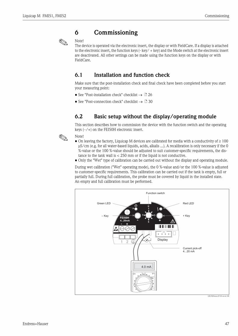
6.2 Basic setup without the display/operating module
This section describes how to commission the device with the function switch and the operating
keys (–/+) on the FEI50H electronic insert.
! Note!
• On leaving the factory, Liquicap M devices are calibrated for media with a conductivity of ≥ 100
μS/cm (e.g. for all water-based liquids, acids, alkalis ...). A recalibration is only necessary if the 0
%-value or the 100 %-value should be adjusted to suit customer-specific requirements, the dis-
tance to the tank wall is < 250 mm or if the liquid is not conductive.
• Only the "Wet" type of calibration can be carried out without the display and operating module.
During wet calibration ("Wet" operating mode), the 0 %-value and/or the 100 %-value is adjusted
to customer-specific requirements. This calibration can be carried out if the tank is empty, full or
partially full. During full calibration, the probe must be covered by liquid in the installed state.
An empty and full calibration must be performed.
L00-FMI5xxxx-07-05-xx-en-100
4.0 mA
V~V=
A
- +
FEI50H4...20mA - +
+ -Display
1
7 3
5
Red LEDGreen LED
Function switch
Current pick-off4...20 mA
+ Key– Key

Commissioning Liquicap M FMI51, FMI52
48 Endress+Hauser
6.2.1 Function switch - position 1
Operation
In normal operation, the function switch must be set to position 1.
6.2.2 Function switch - position 4
Measuring modes
! Note!
Before carrying out empty and full calibration, the medium properties must be configured. If the
medium is conductive and tends to form buildup, the "Buildup" operating mode must be selected.
In this operating mode, the buildup on the probe rod is compensated.
The "No buildup" operating mode is set at the factory.
"Medium property" subfunction
The "No buildup" operating mode should be set for media that do not tend to form buildup on the
probe rod (e.g. water, beverages etc.). As of a conductivity of 100 μS/cm (i.e. all water-based
liquids, acids, alkalis ...), the measured value is independent of the conductivity of the liquid
(independent of concentration fluctuations).
In the "Buildup" operating mode, the buildup compensation function integrated in the software is
activated. In this operating mode, the measured value is independent of the conductivity of the
liquid as of a conductivity of 1000 μS/cm (independent of concentration fluctuations).
This compensates measuring errors caused by conductive media sticking to the probe rod (e.g.
yoghurt). This corresponds to buildup compensation.
Proceed as follows to chose between media forming buildup (e.g. yoghurt) and media not forming
buildup (e.g. water):
• Turn the function switch to position 4
• "Buildup" operating mode
=> Press the + key for media that tend to form buildup.
=> The green LED confirms your entry by flashing three times.
• "No buildup" operating mode
=> Press the – key for media that do not form buildup.
=> The green LED confirms your entry by flashing three times.
6.2.3 Function switch - position 2
Carry out empty calibration (for empty tanks)
If the tank is empty (0 %), the empty calibration sets the signal current to the lower value of 4 mA.
When empty calibration is completed, the current value of 4 mA is displayed at the ammeter.
Proceed as follows to perform empty calibration:
• Turn the function switch to position 2
• Press the – and + keys together for approx. 2 s until the green LED flashes*
=> Release the two keys again.
=> The flashing stops after approx. 5 s.
=> Empty calibration is saved.
* SW version 1.00.00 flashes red.
6.2.4 Function switch - position 2
Carry out empty calibration (for almost empty tanks)
If possible, the exact level of the tank should be known and should not be too large (< 30 %).
Too high a level reduces the accuracy of the zero point (corresponds to the empty tank). An
ammeter must be connected to the current pick-off at the electronic insert.
Liquicap M FMI51, FMI52 Commissioning
Endress+Hauser 49
Let us presume that the level was determined for 15 %. Now the current value that corresponds to
the level of 15 % must be determined. The lower current value can be adjusted with the +/– keys.
The + key increases the value, the – key reduces the value. The following must also be considered:
1. The lower current value (= empty tank, 0 %) is 4 mA.
2. The upper current value (= full tank, 100 %) is 20 mA.
3. This results in a measuring range of 16 mA for a change from 0 % to 100 %,
i.e. 0.16 mA increase in the current for every 1 % increase in the level.
4. For a 15 % level, this is 15 % x 0.16 mA/% which equals 2.4 mA. This must be added to the
4 mA to obtain the current value to be set: 2.4 mA + 4 mA = 6.4 mA.
Proceed as follows to perform empty calibration on a partially filled tank:
• Turn the function switch to position 2
• The current value can be adjusted with the +/– keys. For this purpose, press the + or – key for
at least 2 seconds. You can set the desired current value (> 4 mA) using the mulitmeter con-
nected.
• The empty calibration is saved when you release the key.
6.2.5 Function switch - position 3
Carry out full calibration (for full tanks)
If the tank is full (100 %), the full calibration sets the signal current to the upper value of 20 mA.
When empty calibration is completed, the current value of 20 mA is displayed at the ammeter.
Proceed as follows to perform full calibration:
• Turn the function switch to position 3
• Press the – and + keys together for approx. 2 s until the green LED flashes*
=> Release the two keys again.
=> The flashing stops after approx. 10 s.
=> Full calibration is saved.
* SW version 1.00.00 flashes red.
6.2.6 Function switch - position 3
Carry out full calibration (for almost full tanks)
If possible, the exact level of the tank should be known and should be as large as possible (> 70 %).
Too low a level reduces the accuracy of the upper point (corresponds to the full tank). An ammeter
must be connected to the current pick-off at the electronic insert.
Let us presume that the level was determined for 90 %. Now the current value that corresponds to
the level of 90 % must be determined. The upper current value can be adjusted with the +/– keys.
The + key increases the value, the – key reduces the value.
The following must also be considered:
1. The lower current value (= empty tank, 0 %) is 4 mA.
2. The upper current value (= full tank, 100 %) is 20 mA.
3. This results in a measuring range of 16 mA for a change from 0 % to 100 %,
i.e. 0.16 mA increase in the current for every 1 % increase in the level.
4. For a 90 % level, this is 90 % x 0.16 mA/% which equals 14.4 mA. This must be added to the
4 mA to obtain the current value to be set: 14.4 mA + 4 mA = 18.4 mA. (You can also take
the upper current value and then subtract 10 % x 0.16 mA/% = 1.6 mA from 20 mA.)
Proceed as follows to perform full calibration on a partially filled tank:
• Turn the function switch to position 3

Commissioning Liquicap M FMI51, FMI52
50 Endress+Hauser
• The current value can be adjusted with the +/– keys. For this purpose, press the + or – key for
at least 2 seconds. You can set the desired current value (< 20 mA) using the mulitmeter con-
nected.
• The full calibration is saved when you release the key.
6.2.7 Function switch - position 5
Measuring range
At the factory, the measuring range is always calibrated to the probe length ordered. If the electronic
insert is used in another probe, the measuring range must be configured in accordance with the
probe length.
Proceed as follows to configure the measuring range 2000 pF (probe length < 6 m) or 4000 pF
(probe length > 6 m):
• Turn the function switch to position 5
• Press the – key to set 2000 pF
=> The green LED confirms your entry by flashing three times.
• Press the + key to set 4000 pF
=> The green LED confirms your entry by flashing three times.
6.2.8 Function switch - position 6
Proof test (self-test)
! Note!
• From version FW: V 01.03.00
• Before and after the automatic proof test, it is essential to check whether the level value displayed
corresponds to the actual level value.
When the self-test is activated, the current output is set to 4 mA and follows a ramp function up to
22 mA. This test is completed after approx. 40 s.
Proceed as follows to activate the device self-test:
• Turn the function switch to position 6
• Press the – and + keys together to start the function test
=> The green LED flashes quickly until the error current is reached. The red LED flashes until the
test is completed.
! Note!
After the self-test, the device automatically returns to the operating mode.
6.2.9 Function switch - position 7
Reset - restore factory settings
" Caution!
The reset can affect the measurement as the current values are overwritten by those of the factory
calibration (0 % (4 mA) and 100 % (20 mA)).
Proceed as follows to restore the factory settings:
• Disconnect the electronic insert from the power supply
• Turn the function switch to position 7
• Press and hold the – and + keys together while the device is being reconnected to the power sup-
ply
=> red LED flashes slowly and then starts to flash quickly
• The device reset is complete when the red LED goes out
• Release the – and + keys again
Liquicap M FMI51, FMI52 Commissioning
Endress+Hauser 51
6.2.10 Function switch - position 8
Download/Upload sensor DAT (EEPROM)
Calibration values can be transmitted with this function. A distinction is made between two types:
• The sensor has been replaced and the electronic insert should continue to be used.
• The electronic insert has been replaced but the sensor should continue to be used.
For instances of this nature, the calibration values already set can be transferred from the sensor to
the electronic insert or from the electronic insert to the sensor.
Proceed as follows to transfer the calibration values from the electronic insert to the sensor:
Download
• Turn the function switch to position 8
• Press the – key to start downloading from the electronic insert to the sensor
=> The green LED flashes for approx. 2 s, thereby confirming your entry.
=> The device now restarts.
Proceed as follows to transfer the calibration values from the sensor to the electronic insert:
Upload
• Turn the function switch to position 8
• Press the + key to start uploading from the sensor to the electronic insert
=> The green LED flashes for approx. 2 s, thereby confirming your entry.
=> The device now restarts.

Commissioning Liquicap M FMI51, FMI52
52 Endress+Hauser
6.3 "Basic setup" menu
Commissioning with display and operating module
! Note!
This section describes how to commission the Liquicap M by means of the display and operating
module. The procedure for commissioning by means of FieldCare or the DXR375 handheld terminal
is the same. More detailed information can be found in the Operating Instructions for FieldCare (BA
224F/00) or for DXR375 (is supplied together with the handheld terminal).
6.3.1 Initial commissioning
On first power-up, you are requested to select the language for the display texts.
After this selection the measured value is displayed.
! Note!
If a reset is performed at the device and if the power supply is switched off and on again, the
language of the display texts has to be selected again.
Menu structures: Main menu
The main menu is activated by means of the right Enter key ↵.
The following menu headings appear. These are explained in more detail over the following pages:
• "Basic setup"
• "Safety setting " (→ ä 58)
• "Linearization" (→ ä 62)
• "Output" (→ ä 68)
• "Device properties" (→ ä 72)
! Note!
• Liquicap M devices are calibrated on leaving the factory for media with a conductivity of ≥ 100
μS/cm (e.g. for all water-based liquids, acids, alkalis ...). A recalibration is only necessary if the 0
%-value or the 100 %-value should be adjusted to suit customer-specific requirements, the dis-
tance to the tank wall is < 250 mm or if the liquid is not conductive.
• A distinction is generally made between two types of calibration:
Wet calibration:
During wet calibration ("Wet" operating mode), the probe must be covered by liquid in the
installed state. This calibration can be carried out if the tank is empty, full or partially full. Empty
and full calibration must be performed.
• Dry calibration
During dry calibration, empty and full calibration can be carried out without the probe being in
contact with the liquid. The calibration values can be entered directly in units of length (e.g. m,
mm, ...) for example.
L00-FMI5xxxx-15-05-xx-en-000
100 % / 20 mA
/ 4 mA0 %^
^
100 %(on leaving factory)
0 % = 4.0 mA(on leaving factory)
0 % = 4.0 mA(customer specific)
(customer specific)
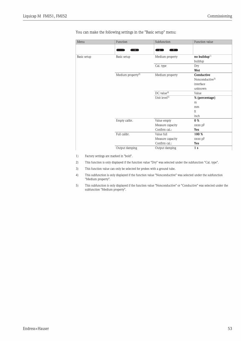
Liquicap M FMI51, FMI52 Commissioning
Endress+Hauser 53
You can make the following settings in the "Basic setup" menu:
Menu Function Subfunction Function value
Basic setup Basic setup Medium property no buildup1)
1) Factory settings are marked in "bold".
buildup
Cal. type Dry
Wet
Medium property2)
2) This function is only displayed if the function value "Dry" was selected under the subfunction "Cal. type".
Medium property Conductive
Nonconductive3)
3) This function value can only be selected for probes with a ground tube.
interface
unknown
DC value4)
4) This subfunction is only displayed if the function value "Nonconductive" was selected under the subfunction
"Medium property".
Value
Unit level5)
5) This subfunction is only displayed if the function value "Nonconductive" or "Conductive" was selected under the
subfunction "Medium property".
% (percentage)
m
mm
ft
inch
Empty calibr. Value empty 0 %
Measure capacity xxxx pF
Confirm cal.: Yes
Full calibr. Value full 100 %
Measure capacity xxxx pF
Confirm cal.: Yes
Output damping Output damping 1 s
↑ ↑↑
↑
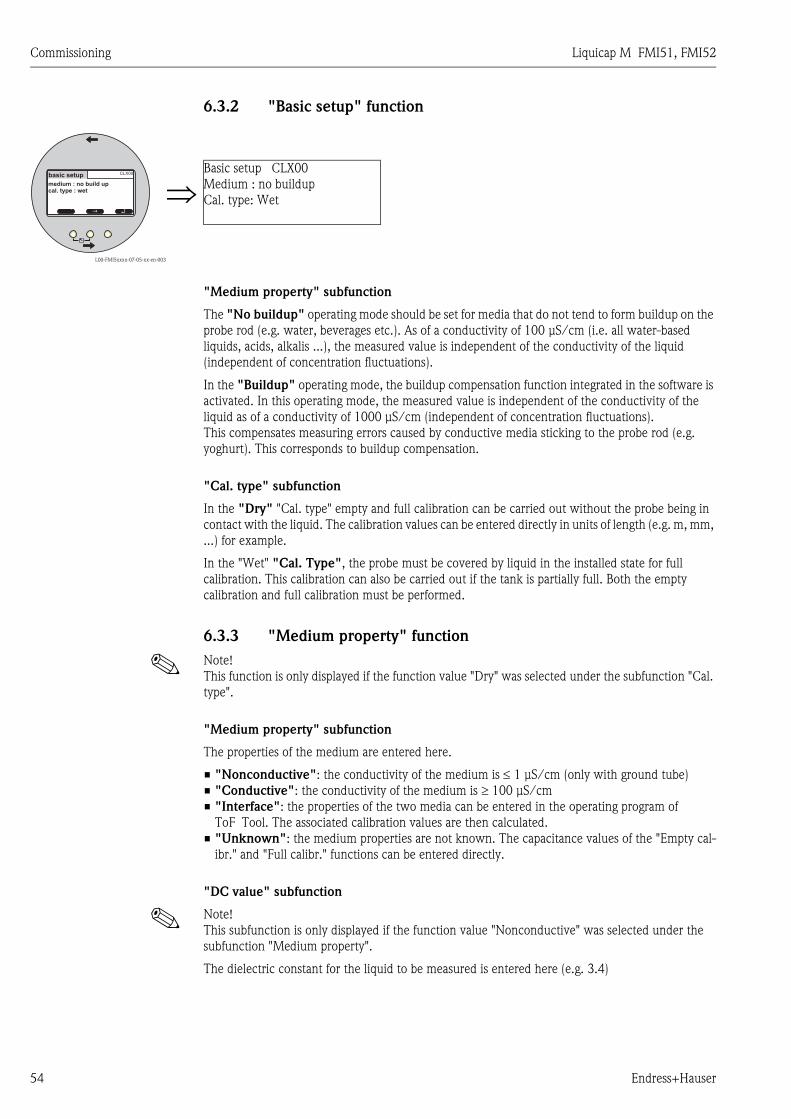
Commissioning Liquicap M FMI51, FMI52
54 Endress+Hauser
6.3.2 "Basic setup" function
"Medium property" subfunction
The "No buildup" operating mode should be set for media that do not tend to form buildup on the
probe rod (e.g. water, beverages etc.). As of a conductivity of 100 μS/cm (i.e. all water-based
liquids, acids, alkalis ...), the measured value is independent of the conductivity of the liquid
(independent of concentration fluctuations).
In the "Buildup" operating mode, the buildup compensation function integrated in the software is
activated. In this operating mode, the measured value is independent of the conductivity of the
liquid as of a conductivity of 1000 μS/cm (independent of concentration fluctuations).
This compensates measuring errors caused by conductive media sticking to the probe rod (e.g.
yoghurt). This corresponds to buildup compensation.
"Cal. type" subfunction
In the "Dry" "Cal. type" empty and full calibration can be carried out without the probe being in
contact with the liquid. The calibration values can be entered directly in units of length (e.g. m, mm,
...) for example.
In the "Wet" "Cal. Type", the probe must be covered by liquid in the installed state for full
calibration. This calibration can also be carried out if the tank is partially full. Both the empty
calibration and full calibration must be performed.
6.3.3 "Medium property" function
! Note!
This function is only displayed if the function value "Dry" was selected under the subfunction "Cal.
type".
"Medium property" subfunction
The properties of the medium are entered here.
• "Nonconductive": the conductivity of the medium is ≤ 1 μS/cm (only with ground tube)
• "Conductive": the conductivity of the medium is ≥ 100 μS/cm
• "Interface": the properties of the two media can be entered in the operating program of
ToF Tool. The associated calibration values are then calculated.
• "Unknown": the medium properties are not known. The capacitance values of the "Empty cal-
ibr." and "Full calibr." functions can be entered directly.
"DC value" subfunction
! Note!
This subfunction is only displayed if the function value "Nonconductive" was selected under the
subfunction "Medium property".
The dielectric constant for the liquid to be measured is entered here (e.g. 3.4)
L00-FMI5xxxx-07-05-xx-en-003
⇒Basic setup CLX00
Medium : no buildup
Cal. type: Wet↵↑ ↑
CLX00basic setup
medium : no build upcal. type : wet

Liquicap M FMI51, FMI52 Commissioning
Endress+Hauser 55
"Unit level" subfunction
! Note!
This subfunction is only displayed if the function value "Conductive" or "Nonconductive" was
selected under "Medium property".
The desired level unit for Basic setup is entered here.
6.3.4 "Empty calibr." function ("Wet" operating mode)
! Note!
The calibration data can be calculated with CapCalc.xls → ä 78.
With "Empty calibration", the 0 % value or the 4 mA value is assigned to the level value.
! Note!
The procedure applies to the "Wet" type of calibration. Information on "Dry" calibration is provided
further below.
"Value empty" subfunction
The current level value is entered here,
e.g. 5 % partial filling => "Value empty" 5 % or
e.g. 0 % partial filling => "Value empty" 0 %
! Note!
To keep the calibration error to a minimum, the level should be between 0 % and 30 %.
"Measure capacity" subfunction
The capacitance value currently measured is displayed here.
"Confirm cal." subfunction
In this function, empty calibration is confirmed and the "Measure capacity" currently measured is
assigned to the percentage level value entered above ("Value empty").
6.3.5 "Full calibr." function ("Wet" operating mode)
With "Full calibration", the 100 % value or the 20 mA value is assigned to the level value.
! Note!
The procedure applies to the "Wet" type of calibration. Information on "Dry" calibration is provided
further below.
"Value full" subfunction
The current level value is entered here,
e.g. 90 % partial filling => "Value full" 90 % or
e.g. 100 % filling => "Value full" 100 %
! Note!
To keep the calibration error to a minimum, the level should be between 70 % and 100 %.
"Measure capacity" subfunction
The capacitance value currently measured is displayed here.
"Confirm cal." subfunction
Full calibration must be confirmed with this function.
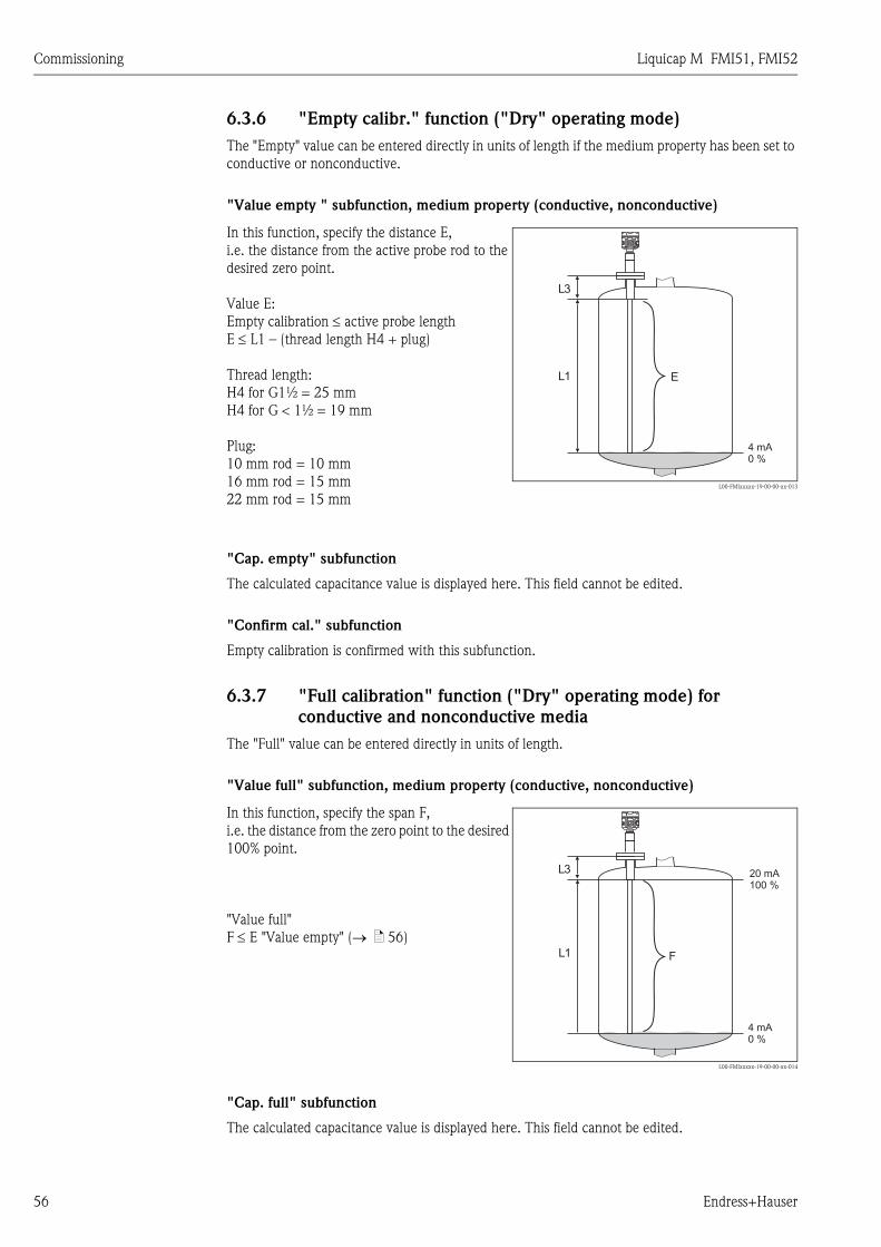
Commissioning Liquicap M FMI51, FMI52
56 Endress+Hauser
6.3.6 "Empty calibr." function ("Dry" operating mode)
The "Empty" value can be entered directly in units of length if the medium property has been set to
conductive or nonconductive.
"Value empty " subfunction, medium property (conductive, nonconductive)
"Cap. empty" subfunction
The calculated capacitance value is displayed here. This field cannot be edited.
"Confirm cal." subfunction
Empty calibration is confirmed with this subfunction.
6.3.7 "Full calibration" function ("Dry" operating mode) for
conductive and nonconductive media
The "Full" value can be entered directly in units of length.
"Value full" subfunction, medium property (conductive, nonconductive)
"Cap. full" subfunction
The calculated capacitance value is displayed here. This field cannot be edited.
In this function, specify the distance E,
i.e. the distance from the active probe rod to the
desired zero point.
Value E:
Empty calibration ≤ active probe length
E ≤ L1 – (thread length H4 + plug)
Thread length:
H4 for G1½ = 25 mm
H4 for G < 1½ = 19 mm
Plug:
10 mm rod = 10 mm
16 mm rod = 15 mm
22 mm rod = 15 mmL00-FMIxxxxx-19-00-00-xx-013
In this function, specify the span F,
i.e. the distance from the zero point to the desired
100% point.
"Value full"
F ≤ E "Value empty" (→ ä 56)
L00-FMIxxxxx-19-00-00-xx-014
E
4 mA0 %
L3
L1
4 mA0 %
L3
L1
20 mA100 %
F
Liquicap M FMI51, FMI52 Commissioning
Endress+Hauser 57
"Confirm cal." subfunction
Full calibration is confirmed with this subfunction.
6.3.8 "Empty calibration" function ("Dry" operating mode for
"Interface" or "Unknown" medium properties)
"Value empty" subfunction
This field displays 0 % and cannot be edited.
"Cap. empty" subfunction
Enter the capacitance value calculated with CapCalc.xls, for example, (capacitance calculation
program in FieldCare) here.
"Confirm cal." subfunction
Empty calibration must be confirmed with this subfunction.
6.3.9 "Full calibration" function ("Dry" operating mode for
"Interface" or "Unknown" medium properties)
"Value full" subfunction
This field displays 100 % and cannot be edited.
"Cap. full" subfunction
The capacitance value calculated with CapCalc.xls, for example, (capacitance calculation program
in FieldCare) is entered here.
"Confirm cal." subfunction
Full calibration must be confirmed with this subfunction.
6.3.10 "Output damping" function
With this function, you can set the reaction time of your measuring device to changes in the level.
If surfaces are turbulent, a higher output damping (e.g. 2 s) should be selected.
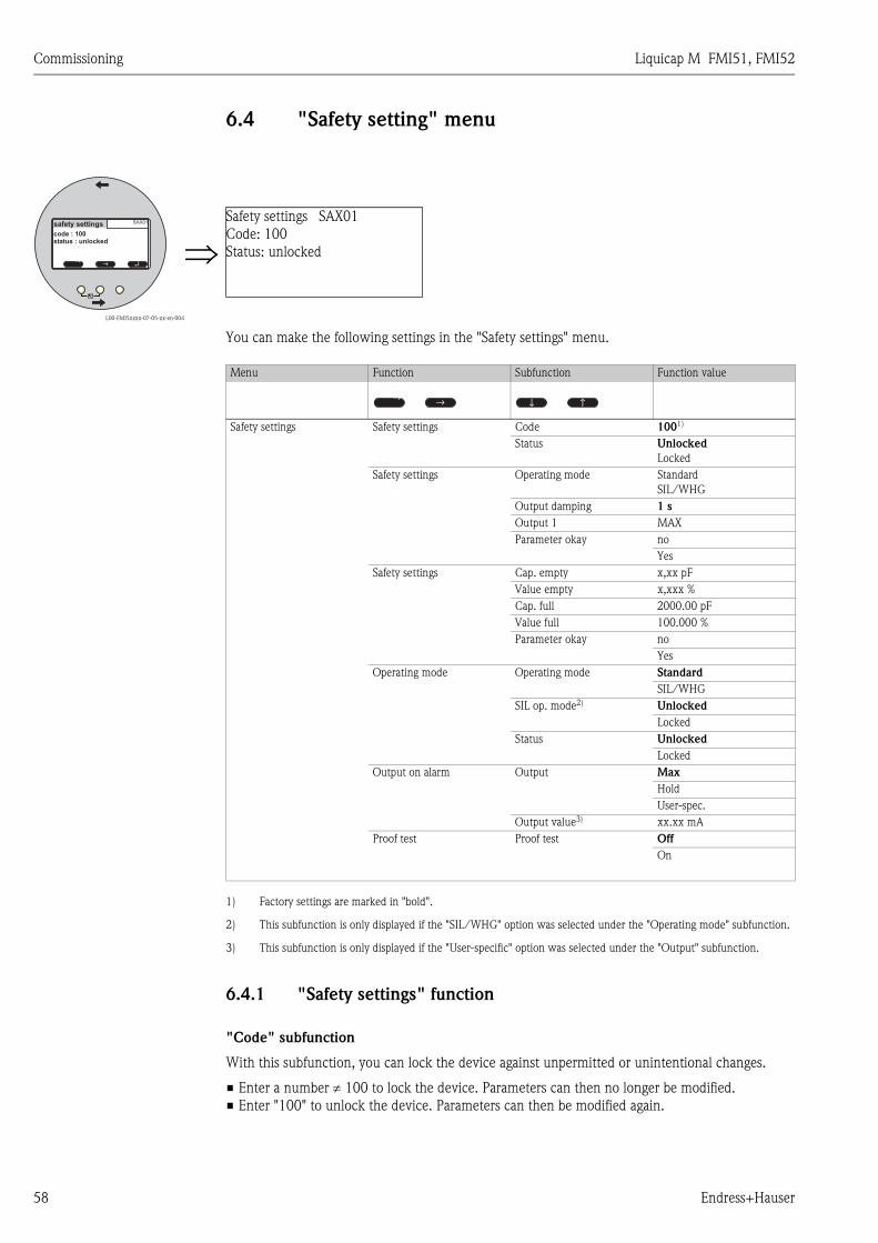
Commissioning Liquicap M FMI51, FMI52
58 Endress+Hauser
6.4 "Safety setting" menu
You can make the following settings in the "Safety settings" menu.
6.4.1 "Safety settings" function
"Code" subfunction
With this subfunction, you can lock the device against unpermitted or unintentional changes.
• Enter a number ≠ 100 to lock the device. Parameters can then no longer be modified.
• Enter "100" to unlock the device. Parameters can then be modified again.
L00-FMI5xxxx-07-05-xx-en-004
⇒Safety settings SAX01
Code: 100
Status: unlocked↵↑ ↑
SAX01safety settings
code : 100status : unlocked
Menu Function Subfunction Function value
Safety settings Safety settings Code 1001)
1) Factory settings are marked in "bold".
Status Unlocked
Locked
Safety settings Operating mode Standard
SIL/WHG
Output damping 1 s
Output 1 MAX
Parameter okay no
Yes
Safety settings Cap. empty x,xx pF
Value empty x,xxx %
Cap. full 2000.00 pF
Value full 100.000 %
Parameter okay no
Yes
Operating mode Operating mode Standard
SIL/WHG
SIL op. mode2)
2) This subfunction is only displayed if the "SIL/WHG" option was selected under the "Operating mode" subfunction.
Unlocked
Locked
Status Unlocked
Locked
Output on alarm Output Max
Hold
User-spec.
Output value3)
3) This subfunction is only displayed if the "User-specific" option was selected under the "Output" subfunction.
xx.xx mA
Proof test Proof test Off
On
↑ ↑↑
↑
Liquicap M FMI51, FMI52 Commissioning
Endress+Hauser 59
"Status" subfunction
This subfunction displays the current locking status of the device. The following values can appear:
• "Unlocked"
All writeable parameters can be modified.
• "Locked"
The device has been locked via the operating menu ("Code" subfunction). It can only be unlocked
by entering "100" in the "Code" subfunction.
6.4.2 "Safety settings" function
"Operating mode" subfunction
This subfunction displays the set operating mode and cannot be edited.
Possible operating modes:
• Standard
• SIL/WHG
"Output damping" subfunction
This subfunction displays the output damping set. Output damping is the time at which the
measuring system reacts to changes in level and is between 0 and 60 seconds.
"Output 1" subfunction
This subfunction displays the set value the output assumes in an alarm condition. Possible values
are:
• MAX (22 mA)
• Hold (the last value is held)
• User-spec.
"Parameter okay" subfunction
With this subfunction, you confirm that the parameter values displayed under the "Safety settings
II" function are correct.
! Note!
The "Parameter okay" subfunction has to be confirmed with "Yes" so the device can be locked for
the SIL/WHG operating mode. In addition, the SIL/WHG function value has to be selected for the
"Operating mode" subfunction and "Locked" must be set for the "Status" subfunction. The device
can be unlocked using the special release code. The release code is "7452".
6.4.3 "Safety settings" function
"Cap. empty" subfunction
This subfunction displays the measured capacitance during empty calibration in pF.
"Value empty" subfunction
This subfunction displays the empty calibration value in %.
"Cap. full" subfunction
This subfunction displays the measured capacitance during full calibration in pF.
"Value full" subfunction
This subfunction displays the full calibration value in %.
Commissioning Liquicap M FMI51, FMI52
60 Endress+Hauser
"Parameter okay" subfunction
With this subfunction, you confirm that the parameter values displayed under the "Safety settings
II" function are correct.
! Note!
The "Parameter okay" subfunction has to be confirmed with "Yes" so the device can be locked for
the SIL/WHG operating mode. In addition, the SIL/WHG function value has to be selected for the
"Operating mode" subfunction and "Locked" must be set for the "Status" subfunction. The device
can be unlocked using the special release code. The release code is "7452".
6.4.4 "Operating mode" function
"Operating mode" subfunction
With this subfunction, you can switch from the Standard operating mode to the SIL/WHG operating
mode:
• "Standard"
• "SIL/WHG"
The following parameters are set to defined values in the "SIL/WHG" operating mode:
• Output damping: Output damping is fixed at "1 s
• Output on alarm: The "Output on alarm" function is fixed at "22 mA".
In the "SIL/WHG" operating mode, cyclic self-monitoring of the device takes place (e.g. memory
test, processor test, current output ...).
"SIL operating mode" subfunction
You can lock or unlock the device in this subfunction. No parameters can be changed in the locked
state.
"Status" subfunction
This subfunction displays the current locking status of the device. The following values can appear:
• "Unlocked"
All writeable parameters can be modified.
• "Locked"
The device has been locked via the operating menu ("Code" subfunction). It can only be unlocked
by entering "100" in the "Code" subfunction.
6.4.5 "Safety settings" function
"Operating mode" subfunction
The "Standard" or "SIL/WHG" operating mode entered is displayed here.
"Output damping" subfunction
The output damping entered is displayed here.
"Value empty" subfunction
The capacitance of the empty calibration is displayed here.
"Value full" subfunction
The capacitance of the full calibration is displayed here.
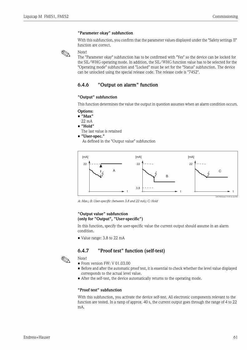
Liquicap M FMI51, FMI52 Commissioning
Endress+Hauser 61
"Parameter okay" subfunction
With this subfunction, you confirm that the parameter values displayed under the "Safety settings II"
function are correct.
! Note!
The "Parameter okay" subfunction has to be confirmed with "Yes" so the device can be locked for
the SIL/WHG operating mode. In addition, the SIL/WHG function value has to be selected for the
"Operating mode" subfunction and "Locked" must be set for the "Status" subfunction. The device
can be unlocked using the special release code. The release code is "7452".
6.4.6 "Output on alarm" function
"Output" subfunction
This function determines the value the output in question assumes when an alarm condition occurs.
Options:
• "Max"
22 mA
• "Hold"
The last value is retained
• "User-spec."
As defined in the "Output value" subfunction
L00-FMI5xxxx-19-05-xx-xx-006
A: Max.; B: User-specific (between 3.8 and 22 mA); C: Hold
"Output value" subfunction
(only for "Output", "User-specific")
In this function, specify the user-specific value the current output should assume in an alarm
condition.
• Value range: 3.8 to 22 mA
6.4.7 "Proof test" function (self-test)
! Note!
• From version FW: V 01.03.00
• Before and after the automatic proof test, it is essential to check whether the level value displayed
corresponds to the actual level value.
• After the self-test, the device automatically returns to the operating mode.
"Proof test" subfunction
With this subfunction, you activate the device self-test. All electronic components relevant to the
function are tested. In a ramp of approx. 40 s, the current output goes through the range of 4 to 22
mA.
t
[mA]
22
t
[mA]
22
3.8t
[mA]
22
A C
B
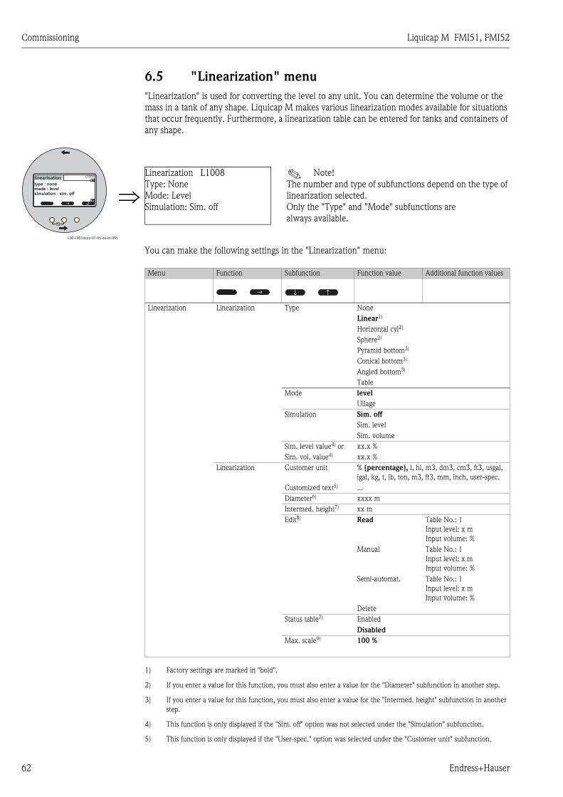
Commissioning Liquicap M FMI51, FMI52
62 Endress+Hauser
6.5 "Linearization" menu
"Linearization" is used for converting the level to any unit. You can determine the volume or the
mass in a tank of any shape. Liquicap M makes various linearization modes available for situations
that occur frequently. Furthermore, a linearization table can be entered for tanks and containers of
any shape.
You can make the following settings in the "Linearization" menu:
L00-FMI5xxxx-07-05-xx-en-005
⇒Linearization L1008
Type: None
Mode: Level
Simulation: Sim. off
! Note!
The number and type of subfunctions depend on the type of
linearization selected.
Only the "Type" and "Mode" subfunctions are
always available.
↵↑ ↑
L1008linearisation
type : nonemode : levelsimulation : sim. off
Menu Function Subfunction Function value Additional function values
Linearization Linearization Type None
Linear1)
1) Factory settings are marked in "bold".
Horizontal cyl2)
2) If you enter a value for this function, you must also enter a value for the "Diameter" subfunction in another step.
Sphere2)
Pyramid bottom3)
3) If you enter a value for this function, you must also enter a value for the "Intermed. height" subfunction in another
step.
Conical bottom3)
Angled bottom3)
Table
Mode level
Ullage
Simulation Sim. off
Sim. level
Sim. volume
Sim. level value4) or
4) This function is only displayed if the "Sim. off" option was not selected under the "Simulation" subfunction.
xx.x %
Sim. vol. value4) xx.x %
Linearization Customer unit % (percentage), l, hl, m3, dm3, cm3, ft3, usgal,
igal, kg, t, lb, ton, m3, ft3, mm, inch, user-spec.
Customized text5)
5) This function is only displayed if the "User-spec." option was selected under the "Customer unit" subfunction.
...
Diameter6) xxxx m
Intermed. height7) xx m
Edit8) Read Table No.: 1
Input level: x m
Input volume: %
Manual Table No.: 1
Input level: x m
Input volume: %
Semi-automat. Table No.: 1
Input level: x m
Input volume: %
Delete
Status table7) Enabled
Disabled
Max. scale9) 100 %
↑ ↑↑
↑
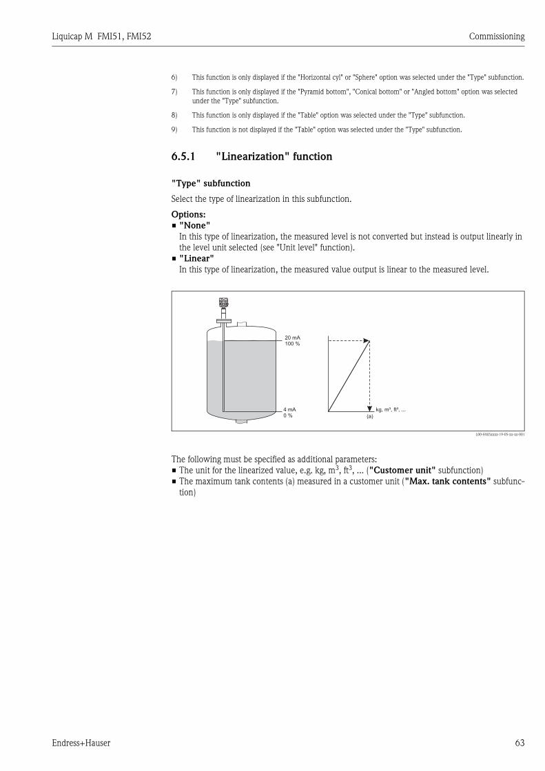
Liquicap M FMI51, FMI52 Commissioning
Endress+Hauser 63
6.5.1 "Linearization" function
"Type" subfunction
Select the type of linearization in this subfunction.
Options:
• "None"
In this type of linearization, the measured level is not converted but instead is output linearly in
the level unit selected (see "Unit level" function).
• "Linear"
In this type of linearization, the measured value output is linear to the measured level.
L00-FMI5xxxx-19-05-xx-xx-001
The following must be specified as additional parameters:
• The unit for the linearized value, e.g. kg, m3, ft3, ... ("Customer unit" subfunction)
• The maximum tank contents (a) measured in a customer unit ("Max. tank contents" subfunc-
tion)
6) This function is only displayed if the "Horizontal cyl" or "Sphere" option was selected under the "Type" subfunction.
7) This function is only displayed if the "Pyramid bottom", "Conical bottom" or "Angled bottom" option was selected
under the "Type" subfunction.
8) This function is only displayed if the "Table" option was selected under the "Type" subfunction.
9) This function is not displayed if the "Table" option was selected under the "Type" subfunction.
4 mA0 %
kg, m³, ft³, ...
(a)
20 mA100 %
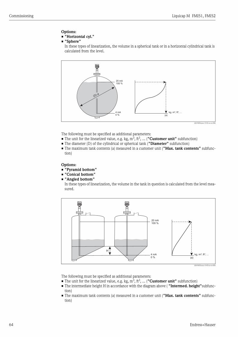
Commissioning Liquicap M FMI51, FMI52
64 Endress+Hauser
Options:
• "Horizontal cyl."
• "Sphere"
In these types of linearization, the volume in a spherical tank or in a horizontal cylindrical tank is
calculated from the level.
L00-FMI5xxxx-19-05-xx-xx-002
The following must be specified as additional parameters:
• The unit for the linearized value, e.g. kg, m3, ft3, ... ("Customer unit" subfunction)
• The diameter (D) of the cylindrical or spherical tank ("Diameter" subfunction)
• The maximum tank contents (a) measured in a customer unit ("Max. tank contents" subfunc-
tion)
Options:
• "Pyramid bottom"
• "Conical bottom"
• "Angled bottom"
In these types of linearization, the volume in the tank in question is calculated from the level mea-
sured.
L00-FMI5xxxx-19-05-xx-xx-003
The following must be specified as additional parameters:
• The unit for the linearized value, e.g. kg, m3, ft3, ... ("Customer unit" subfunction)
• The intermediate height H in accordance with the diagram above ( "Intermed. height"subfunc-
tion)
• The maximum tank contents (a) measured in a customer unit ("Max. tank contents" subfunc-
tion)
4 mA0 %
kg, m³, ft³, ...
(a)
20 mA100 %
(D) ø
H
4 mA0 %
kg, m³, ft³, ...
(a)
20 mA100 %

Liquicap M FMI51, FMI52 Commissioning
Endress+Hauser 65
Options:
• "Table"
In this type of linearization, the measured value is calculated using a linearization table. The table
can comprise up to 32 "Level - Volume" value pairs. The table must be monotone.
L00-FMI5xxxx-19-05-xx-xx-004
The following must be specified as additional parameters:
• The unit for the linearized value ("Customer unit" subfunction)
• The linearization table ("Edit" subfunction)
"Mode" subfunction
"Simulation" subfunction
In this subfunction, you can simulate the level or the volume by entering a level under "Sim. level
value" or a volume under "Sim. vol. value".
"Sim. level value" or "Sim. vol. value" subfunction
In this subfunction, you can enter the level or volume value to be simulated.
6.5.2 "Linearization" function
"Customer unit" subfunction
In this function, enter the desired unit for the linearized values (e.g. kg, m3, ft3, ...).
kg, m³, ft³, ...4 mA0 %
20 mA100 %
In this function, specify whether
the measurement should refer to level A or to the
empty area B.
L00-FMI5xxxx-19-05-xx-xx-005
B
A
4 mA0 %
20 mA100 %
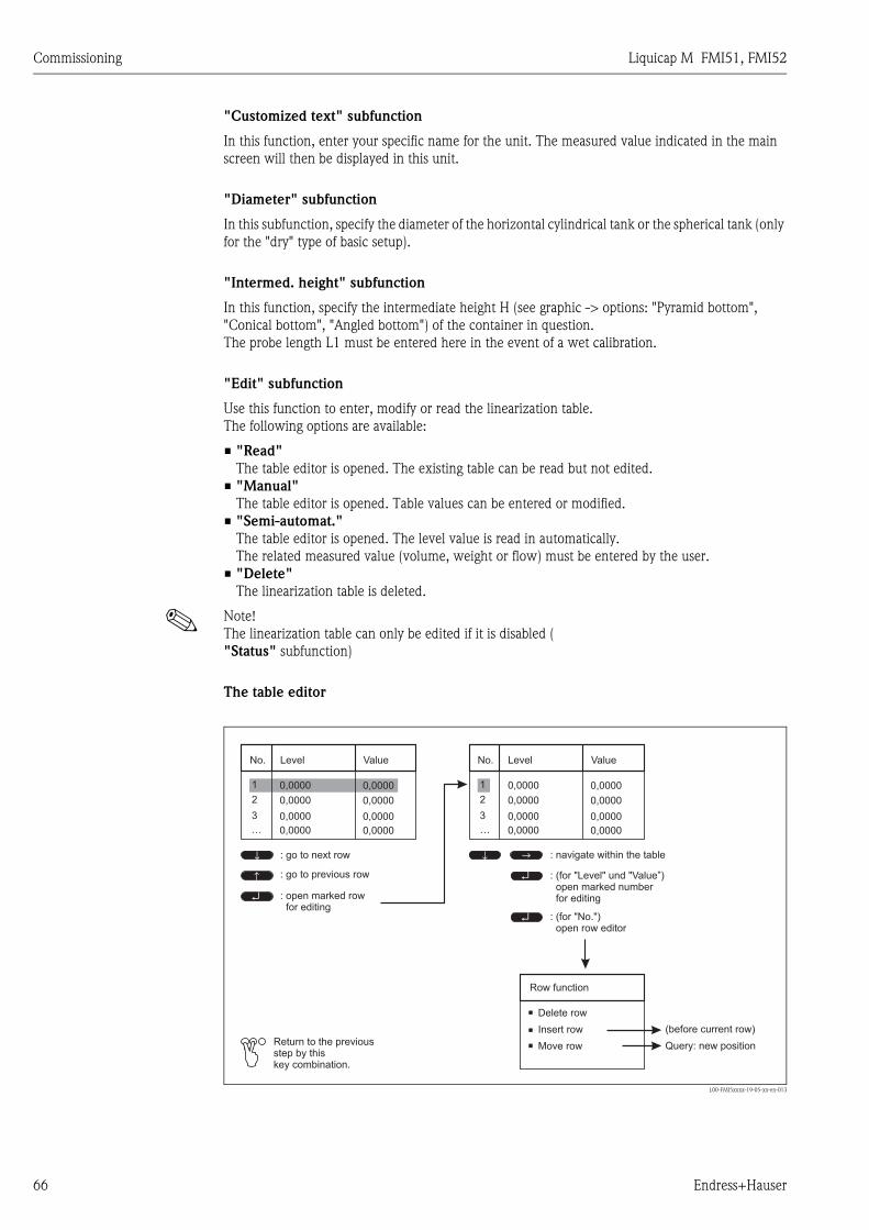
Commissioning Liquicap M FMI51, FMI52
66 Endress+Hauser
"Customized text" subfunction
In this function, enter your specific name for the unit. The measured value indicated in the main
screen will then be displayed in this unit.
"Diameter" subfunction
In this subfunction, specify the diameter of the horizontal cylindrical tank or the spherical tank (only
for the "dry" type of basic setup).
"Intermed. height" subfunction
In this function, specify the intermediate height H (see graphic -> options: "Pyramid bottom",
"Conical bottom", "Angled bottom") of the container in question.
The probe length L1 must be entered here in the event of a wet calibration.
"Edit" subfunction
Use this function to enter, modify or read the linearization table.
The following options are available:
• "Read"
The table editor is opened. The existing table can be read but not edited.
• "Manual"
The table editor is opened. Table values can be entered or modified.
• "Semi-automat."
The table editor is opened. The level value is read in automatically.
The related measured value (volume, weight or flow) must be entered by the user.
• "Delete"
The linearization table is deleted.
! Note!
The linearization table can only be edited if it is disabled (
"Status" subfunction)
The table editor
L00-FMI5xxxx-19-05-xx-en-013
1 0,0000 0,0000
2 0,0000 0,0000
3 0,0000 0,0000
… 0,0000 0,0000
1 0,0000 0,0000
2 0,0000 0,0000
3 0,0000 0,0000
… 0,0000 0,0000
↵
↵
↵
↑ ↑
↑
↑
No. No.Level LevelValue Value
: go to next row
: go to previous row
: open marked rowfor editing
: navigate within the table
: (for "Level" und "Value”)open marked numberfor editing
: (for "No.")open row editor
Row function
(before current row)
Query: new positionReturn to the previousstep by thiskey combination.
Insert row
Move row
Delete row
Liquicap M FMI51, FMI52 Commissioning
Endress+Hauser 67
"Status table" subfunction
In this function, you can specify whether the linearization table should be used or not.
Options:
• "Enabled"
The table is used.
• "Disabled"
The table is not used. The measured value is output linearly with regard to the level unit.
"Max. scale" subfunction
In this function, specify the maximum contents of the tank in question in the customer unit.
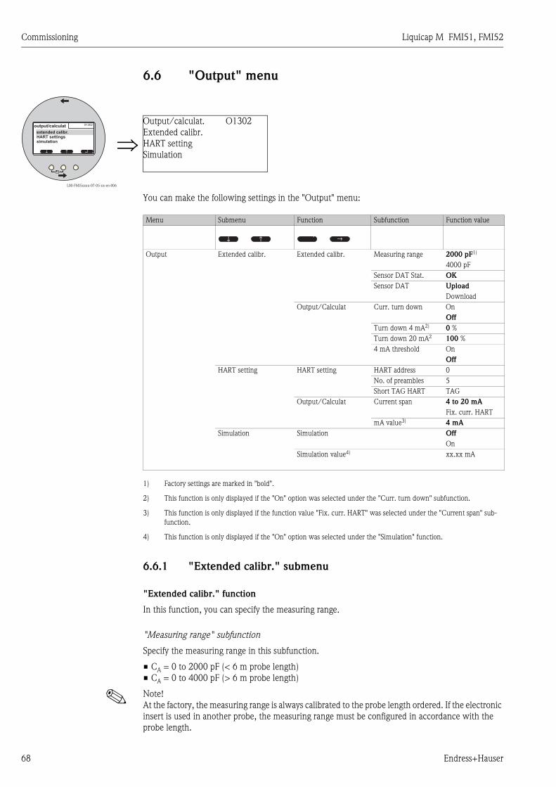
Commissioning Liquicap M FMI51, FMI52
68 Endress+Hauser
6.6 "Output" menu
You can make the following settings in the "Output" menu:
6.6.1 "Extended calibr." submenu
"Extended calibr." function
In this function, you can specify the measuring range.
"Measuring range" subfunction
Specify the measuring range in this subfunction.
• CA = 0 to 2000 pF (< 6 m probe length)
• CA = 0 to 4000 pF (> 6 m probe length)
! Note!
At the factory, the measuring range is always calibrated to the probe length ordered. If the electronic
insert is used in another probe, the measuring range must be configured in accordance with the
probe length.
L00-FMI5xxxx-07-05-xx-en-006
⇒Output/calculat. O1302
Extended calibr.
HART setting
Simulation ↵↑
↑
01302output/calculat
extended calibr.HART settingssimulation
Menu Submenu Function Subfunction Function value
Output Extended calibr. Extended calibr. Measuring range 2000 pF1)
1) Factory settings are marked in "bold".
4000 pF
Sensor DAT Stat. OK
Sensor DAT Upload
Download
Output/Calculat Curr. turn down On
Off
Turn down 4 mA2)
2) This function is only displayed if the "On" option was selected under the "Curr. turn down" subfunction.
0 %
Turn down 20 mA2 100 %
4 mA threshold On
Off
HART setting HART setting HART address 0
No. of preambles 5
Short TAG HART TAG
Output/Calculat Current span 4 to 20 mA
Fix. curr. HART
mA value3)
3) This function is only displayed if the function value "Fix. curr. HART" was selected under the "Current span" sub-
function.
4 mA
Simulation Simulation Off
On
Simulation value4)
4) This function is only displayed if the "On" option was selected under the "Simulation" function.
xx.xx mA
↑↑
↑ ↑

Liquicap M FMI51, FMI52 Commissioning
Endress+Hauser 69
"Output/Calculat." function
"Sensor DAT stat." subfunction
This subfunction shows the status of the sensor DAT.
• OK (Sensor DAT is ready for use).
• Error (Sensor DAT is not ready for use ore or missing).
"Sensor DAT" subfunction
Calibration values can be transmitted with this function. A distinction is made between two types:
• The sensor has been replaced and the electronic insert should continue to be used.
• The electronic insert has been replaced but the sensor should continue to be used.
For instances of this nature, the calibration values already set can be transferred from the sensor to
the electronic insert or from the electronic insert to the sensor.
Upload
To transfer the calibration values from the sensor to the electronic insert.
Download
To transfer the calibration values from the electronic insert to the sensor.
"Curr. turn down" subfunction
With this function, you can switch on the current turn down. The current output then only refers
to a (freely definable) part of the measuring range. This is then magnified when displayed.
"Curr. turn down" subfunction (not available for "Current span", "Fix. curr. HART")
With this function, you can switch on the current turn down. The current output then only refers
to a (freely definable) part of the measuring range. This is then magnified when displayed.
"Turn down 4 mA" subfunction (only for "Curr. turn down", "On")
In this function, enter the measured value at which the current should be 4 mA.
"Turn down 20 mA" subfunction (only for "Curr. turn down", "On")
In this function, enter the measured value at which the current should be 20 mA.
L00-FMI5xxxx-19-05-xx-xx-009
A: Turn down 4 mA; B: turn down 20 mA
[mA]
20
4
100 [%, ...]0 A B
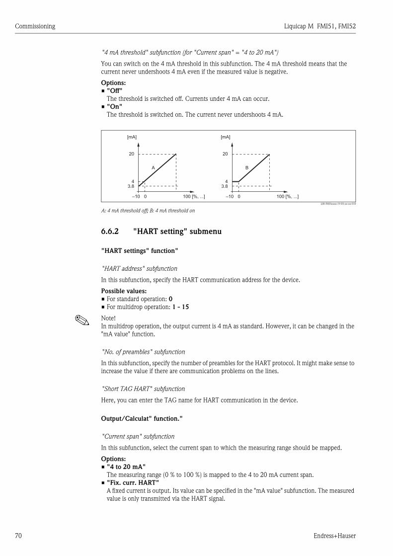
Commissioning Liquicap M FMI51, FMI52
70 Endress+Hauser
"4 mA threshold" subfunction (for "Current span" = "4 to 20 mA")
You can switch on the 4 mA threshold in this subfunction. The 4 mA threshold means that the
current never undershoots 4 mA even if the measured value is negative.
Options:
• "Off"
The threshold is switched off. Currents under 4 mA can occur.
• "On"
The threshold is switched on. The current never undershoots 4 mA.
L00-FMI5xxxx-19-05-xx-xx-010
A: 4 mA threshold off; B: 4 mA threshold on
6.6.2 "HART setting" submenu
"HART settings" function"
"HART address" subfunction
In this subfunction, specify the HART communication address for the device.
Possible values:
• For standard operation: 0
• For multidrop operation: 1 - 15
! Note!
In multidrop operation, the output current is 4 mA as standard. However, it can be changed in the
"mA value" function.
"No. of preambles" subfunction
In this subfunction, specify the number of preambles for the HART protocol. It might make sense to
increase the value if there are communication problems on the lines.
"Short TAG HART" subfunction
Here, you can enter the TAG name for HART communication in the device.
Output/Calculat" function."
"Current span" subfunction
In this subfunction, select the current span to which the measuring range should be mapped.
Options:
• "4 to 20 mA"
The measuring range (0 % to 100 %) is mapped to the 4 to 20 mA current span.
• "Fix. curr. HART"
A fixed current is output. Its value can be specified in the "mA value" subfunction. The measured
value is only transmitted via the HART signal.
[mA] [mA]
20 20
4 4
100 [%, ...] 100 [%, ...]–10 0 –10 0
A B
3.8 3.8
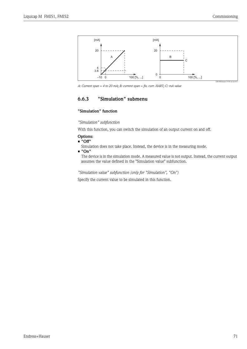
Liquicap M FMI51, FMI52 Commissioning
Endress+Hauser 71
L00-FMI5xxxx-19-05-xx-xx-011
A: Current span = 4 to 20 mA; B: current span = fix. curr. HART; C: mA value
6.6.3 "Simulation" submenu
"Simulation" function
"Simulation" subfunction
With this function, you can switch the simulation of an output current on and off.
Options:
• "Off"
Simulation does not take place. Instead, the device is in the measuring mode.
• "On"
The device is in the simulation mode. A measured value is not output. Instead, the current output
assumes the value defined in the "Simulation value" subfunction.
"Simulation value" subfunction (only for "Simulation", "On")
Specify the current value to be simulated in this function.
[mA] [mA]
20 20
4
100 [%, ...] 100 [%, ...]–10 0 00
A
C
B
3.8
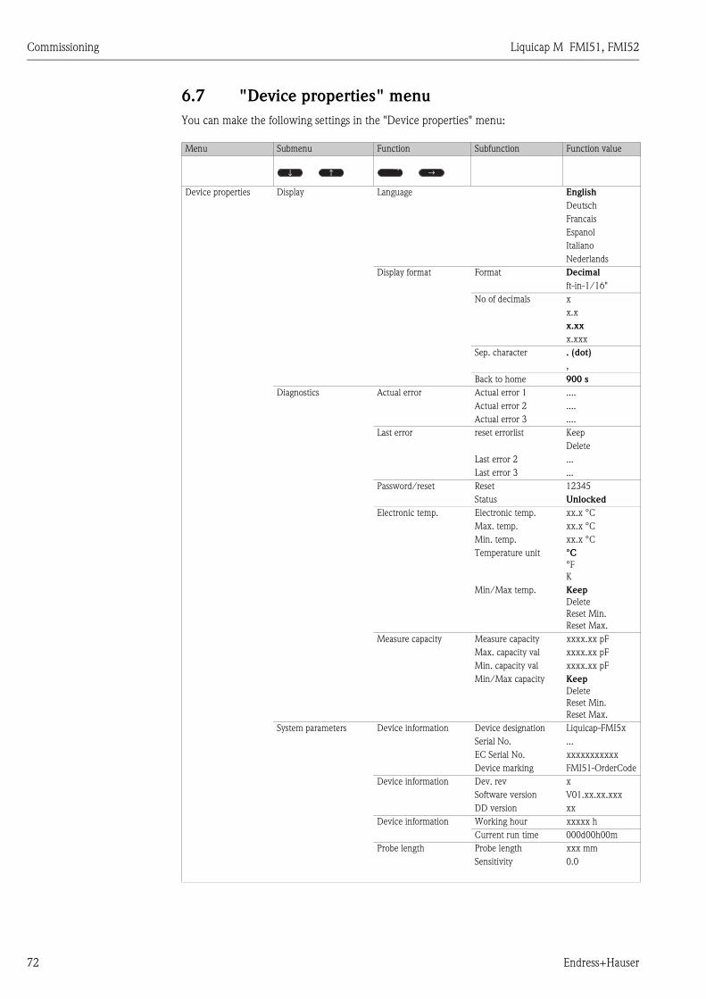
Commissioning Liquicap M FMI51, FMI52
72 Endress+Hauser
6.7 "Device properties" menu
You can make the following settings in the "Device properties" menu:
Menu Submenu Function Subfunction Function value
Device properties Display Language English
Deutsch
Francais
Espanol
Italiano
Nederlands
Display format Format Decimal
ft-in-1/16"
No of decimals x
x.x
x.xx
x.xxx
Sep. character . (dot)
,
Back to home 900 s
Diagnostics Actual error Actual error 1 ....
Actual error 2 ....
Actual error 3 ....
Last error reset errorlist Keep
Delete
Last error 2 ...
Last error 3 ...
Password/reset Reset 12345
Status Unlocked
Electronic temp. Electronic temp. xx.x °C
Max. temp. xx.x °C
Min. temp. xx.x °C
Temperature unit °C
°F
K
Min/Max temp. Keep
Delete
Reset Min.
Reset Max.
Measure capacity Measure capacity xxxx.xx pF
Max. capacity val xxxx.xx pF
Min. capacity val xxxx.xx pF
Min/Max capacity Keep
Delete
Reset Min.
Reset Max.
System parameters Device information Device designation Liquicap-FMI5x
Serial No. ...
EC Serial No. xxxxxxxxxxx
Device marking FMI51-OrderCode
Device information Dev. rev x
Software version V01.xx.xx.xxx
DD version xx
Device information Working hour xxxxx h
Current run time 000d00h00m
Probe length Probe length xxx mm
Sensitivity 0.0
↑↑
↑ ↑
Liquicap M FMI51, FMI52 Commissioning
Endress+Hauser 73
6.7.1 "Display" submenu
"Language" function
In this function, select the language for the display and operating module.
Options:
• "English"
• "Deutsch"
• "Français"
• "Español"
• "Italiano"
• "Nederlands"
"Display format" function
The "Display format" refers to how the measured value is displayed.
"Format" subfunction
In this subfunction, select the display format for displaying numbers.
Options:
• "Decimal"
• "ft-in-1/16"
"No. of decimals" subfunction
In this subfunction, select the number of places after the decimal point for displaying numbers.
Options:
• "x"
• "x.x"
• "x.xx"
• "x.xxx"
"Sep. character" subfunction
In this function, select the separator for displaying decimal numbers.
Options:
• "Dot (.)"
• "Comma (,)"
6.7.2 "Diagnosis" submenu
"Actual error" function
With this function, you can call up a list of the errors currently pending. The errors are arranged by
priority. If you select an error, a text field appears with a brief description of the error (e.g. probe
incorrectly calibrated, operating temperature too high, electronics error), (see also "Error code list"
in Section 9, "Troubleshooting").
"Last error" function
With this function, you can call up a list of the errors last rectified. You also have the option of
resetting the error list (with "reset errorlist"). This overwrites the last three error codes with 0.
"Password/reset" function
With this function, you can restore the factory settings. All parameters are reset to their factory
setting.

Commissioning Liquicap M FMI51, FMI52
74 Endress+Hauser
"Reset" subfunction
In this subfunction, enter the reset code ("333" or "7864") to reset all the parameters to their factory
setting.
• The factory settings of the parameters are marked in bold in the menu overview.
• During a "333" reset, linearization is reset to "linear". However, any linearization table available
is retained and can be activated again where necessary.
The following subfunctions (marked with an asterisk (*)) are also reset.
• During a "7864" reset, linearization is reset to "linear" and the linearization table deleted.
"Electronic temp." function
In this function, you can have temperatures displayed that were measured by the electronic insert
during operation.
"Electronic temp." subfunction *
This subfunction displays the electronics temperature currently measured.
"Max. temp." subfunction *
This subfunction displays the highest temperature value measured by the device.
"Min. temp." subfunction
This subfunction displays the lowest temperature value measured by the device.
"Temperature unit" subfunction
In this subfunction, you can determine the unit in which the temperature should be displayed. The
following options are available:
• "°C"
• "°F"
• " K"
"Min/Max temp." subfunction
In this subfunction, you delete or individually reset the "Min. or Max. temp".
"Measure capacity" function
In this function, you can have measuring capacities displayed that were measured by the electronic
insert during operation.
"Measure capacity" subfunction
This subfunction displays the measuring capacity currently measured.
"Max. capacity val." subfunction *
This subfunction displays the highest capacitance value measured by the device.
"Min. capacity val." subfunction *
This subfunction displays the lowest capacitance value measured by the device.
"Min/Max capacity" subfunction
In this subfunction, you delete or individually reset the "Min. or Max. capacity".
Liquicap M FMI51, FMI52 Commissioning
Endress+Hauser 75
6.7.3 "System parameters" submenu
! Note!
All functions listed below can be viewed only.
"Device information" (I) function
In this function, device information, with which the device can be identified, can be displayed.
"Device marking" subfunction
This subfunction displays the device name (e.g. Liquicap M-FMI51).
"Serial No." subfunction
This subfunction displays the serial number of the device that was assigned in the factory.
"EC Serial No." subfunction
This subfunction displays the serial number of the electronic insert.
"Device marking" subfunction
This subfunction displays the device marking and the order code.
"Dev. rev" subfunction
This subfunction displays the version of the electronic-hardware.
"Software version" subfunction
This subfunction displays the software version of the device that was assigned in the factory.
"DD version" subfunction
This function indicates the DD version with which this device can be operated using FieldCare.
"Working hour" subfunction
This subfunction displays the number of operating hours.
"Current run time" subfunction
This subfunction displays the "current run time" of the device. The first three digits display the
number of days, followed by "d". The next two digits display the hours, followed by "h". The last
two digits indicate the minutes.
"Probe length" function
In this function, more probe information can be displayed.
"Probe length" subfunction
You can read off the current probe length in this subfunction.
Probe length = L1 – (thread length – plug)
See also "Empty calibration" → ä 56.
"Sensitivity" subfunction
You can read off the current sensitivity in mm/pF in this subfunction.

Commissioning Liquicap M FMI51, FMI52
76 Endress+Hauser
6.8 Operation
After Basic setup, Liquicap M outputs the measured value via
• the display and operating module
• the current output
(the entire measuring range (0 % to 100 %) is then mapped to the range (4 to 20 mA) of the cur-
rent output.
• the digital HART signal.
6.9 FieldCare: operating program from Endress+Hauser
The FieldCare operating program is Endress+Hauser's plant asset management tool based on FDT
technology. You can use FieldCare to configure all Endress+Hauser devices as well as third-party
devices which support the FDT standard. The following operating systems are supported: Windows
2000, Windows XP and Windows Vista.
FieldCare supports the following functions:
• Configuration of transmitters in online operation
• Tank linearization
• Loading and saving device data (upload/download)
• Documentation of the measuring point
Connection options:
HART via Commubox FXA195 and the USB port of a computer
! Note!
After reinstalling FieldCare, or by clicking a link in the Help menu, a video can be activated that
explains the possible applications of the program in just a few minutes.
Startup_screen_de.tif

Liquicap M FMI51, FMI52 Commissioning
Endress+Hauser 77
6.9.1
Menu-guided commissioning:
Basic setup:

Commissioning Liquicap M FMI51, FMI52
78 Endress+Hauser
6.9.2 Interface measurement
If there are different media in the container (e.g. water and oil), the capacitance values for "Empty
calibration" and "Full calibration" can be calculated.
CapCalc.xls is a capacitance calculation program in FieldCare which can be used to calculate the
calibration values for level measurement and interface measurement.
L00-FMI5xxxx-15-05-xx-xx-000
1.) e.g. water (the medium must be conductive ≥ 100 μS/cm)
2.) emulsion
3.) e.g. oil ( nonconductive medium < 1 μS/cm and DC < 5)
The program calculates the calibration values on the basis of the data entered (e.g. probe length,
probe type, medium properties etc.). The secure functioning of interface measurement can already
be determined at this time.
The calculated calibration values can be transmitted to the FEI50H electronic insert via the display
or Fieldcare.
! Note!
Generally speaking, capacitance interface measurement is also suitable for very pronounced
emulsion layers. The emulsion layer average is always measured.
1.)
2.)
3.)
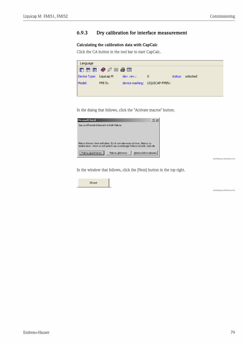
Liquicap M FMI51, FMI52 Commissioning
Endress+Hauser 79
6.9.3 Dry calibration for interface measurement
Calculating the calibration data with CapCalc
Click the CA button in the tool bar to start CapCalc.
In the dialog that follows, click the "Activate macros" button.
L00-FMIxxxxx-20-00-00-en-018
In the window that follows, click the [Next] button in the top right.
L00-FMIxxxxx-20-00-00-en-019
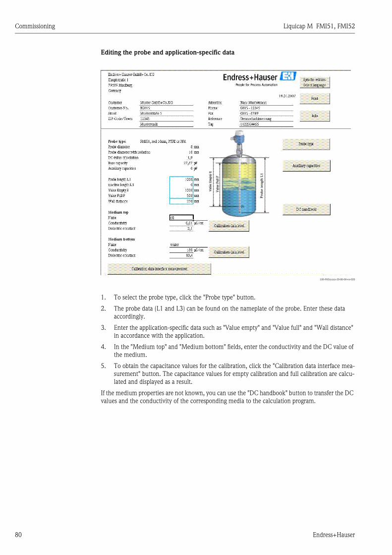
Commissioning Liquicap M FMI51, FMI52
80 Endress+Hauser
Editing the probe and application-specific data
L00-FMIxxxxx-20-00-00-en-020
1. To select the probe type, click the "Probe type" button.
2. The probe data (L1 and L3) can be found on the nameplate of the probe. Enter these data
accordingly.
3. Enter the application-specific data such as "Value empty" and "Value full" and "Wall distance"
in accordance with the application.
4. In the "Medium top" and "Medium bottom" fields, enter the conductivity and the DC value of
the medium.
5. To obtain the capacitance values for the calibration, click the "Calibration data interface mea-
surement" button. The capacitance values for empty calibration and full calibration are calcu-
lated and displayed as a result.
If the medium properties are not known, you can use the "DC handbook" button to transfer the DC
values and the conductivity of the corresponding media to the calculation program.
Liquicap M FMI51, FMI52 Commissioning
Endress+Hauser 81
6.9.4 Wet calibration for interface measurement
This chapter describes the wet calibration procedure for "Empty calibration" and "Full calibration".
"Empty calibration"
1. Fill the container with the top medium and perform "Empty calibration" 0 % (see basic setup
→ ä 52)
If it is not possible to fill with medium, "Empty calibration" can also be performed with the
probe exposed (in the air). A calibration inaccuracy of approx. 2.5 % per meter should be
expected here (oil and water are the reference media).
"Full calibration"
2. Fill the container with the bottom medium and perform "Full calibration" 100 % (see basic
setup → ä 52)
You have now performed basic setup.
6.9.5 Empty and full calibration completed
You have now performed empty and full calibration and saved the values in the electronic insert
and the sensor DAT.
Maintenance Liquicap M FMI51, FMI52
82 Endress+Hauser
7 Maintenance
No special maintenance work is required for the Liquicap M level transmitter.
External cleaning
When externally cleaning Liquicap M, make sure that the cleaning agent used does not attack or
corrode the housing surface or seals.
Cleaning the probe
Depending on the application, buildup (contamination and soiling) can form on the probe rod. A
high degree of material buildup can affect the measurement result. If the medium tends to create a
high degree of buildup, regular cleaning is recommended. When hosing down or during mechanical
cleaning, it is important to make sure that the insulation of the probe rod is not damaged. If cleaning
agents are used make sure the material is resistant to them!
Seals
The process seals of the sensor should be replaced periodically, especially when using molded seals
(aseptic version)! The intervals between seal replacement depend on the frequency of the cleaning
cycles and on the fluid and cleaning temperature.
Repair
The Endress+Hauser repair concept is devised in such a way that the devices have a modular design
and repairs can be carried out by the customers.
Spare parts are grouped into handy kits with related replacement instructions. The "Spare parts"
section lists all the spare part kits, including the order numbers, which you can order from
Endress+Hauser for repairing Liquicap M. For further information on service and spare parts, please
contact Endress+Hauser Service.
Repairing Ex-certified devices
The following information also has to be taken into account when repairing Ex-certified devices:
• Ex-certified devices may only be repaired by experienced, skilled staff or by Endress+Hauser Ser-
vice.
• Applicable standards, national Ex-area regulations as well as the Safety Instructions (XA) and cer-
tificates must be observed.
• Only genuine spare parts from Endress+Hauser may be used.
• When ordering spare parts, please note the device designation on the nameplate. Parts can only
be replaced by the same parts.
• Repairs must be carried out in accordance with the instructions. Following a repair, the individual
testing specified for the device must be carried out.
• Certified devices can only be converted to other certified device versions by Endress+Hauser Ser-
vice.
• Every repair and conversion made to the device must be documented.
Replacement
After replacing a Liquicap M or the electronic insert, the calibration values must be transferred to
the replacement device.
• When the probe is replaced, the calibration values in the electronic insert can be transferred to
the sensor DAT (EEPROM) module via a manual download.
• When the electronic insert is replaced, the calibration values of the sensor DAT (EEPROM) mod-
ule can be transferred to the electronics via a manual upload.
This means that you can restart the device without having to carry out a new calibration. (→ ä 51
Sensor DAT (EEPROM) Upload/download.)
Liquicap M FMI51, FMI52 Accessories
Endress+Hauser 83
8 Accessories
8.1 Protective cover
For F13 and F17 housing
Order number: 71040497
For F16 housing
Order number: 71127760
8.2 Shortening set for FMI52
For Liquicap M FMI52 (no hygienic approval: EHEDG, 3A)
Order number: 942901-0001
8.3 Commubox FXA195 HART
For intrinsically safe HART communication with FieldCare via the RS232C interface or USB.
8.4 HAW56x surge arrester
Surge arrester for limiting overvoltage in signal lines and components: see Technical Information
TI00401F.
8.5 Weld-in adapter
All the weld-in adapters available are described in the document TI00426F.
www.endress.com É Country É Download É Advanced É Documentation code É TI00426F.
Troubleshooting Liquicap M FMI51, FMI52
84 Endress+Hauser
9 Troubleshooting
The operating status of the device is indicated by the LEDs on the electronic insert.
9.1 Error messages at electronic insert
9.1.1 Green LED flashing
Green LED ( indicates operation):
• Flashes every 5 s:
– Indicates whether the device is operational
• Flashes once every s:
– The device is in the calibration mode
• Flashes 4 times:
– The device confirms a parameter change (function switch position 4, 5, 6)
9.1.2 Red LED flashing ( indicates a fault)
Warning
• Flashes five times a s:
– Capacitance at probe is too large
– Probe insulation break detection
– FEI50H is defective
The reasons for warnings include:
Alarm
• Flashes once every s:
The temperature in the electronic insert is outside the permitted temperature range.
! Note!
For more accurate error analysis, see → ä 85 "Error codes".
9.2 System error messages
9.2.1 Error signal
Errors occurring during commissioning or during operation are displayed as follows:
• Error symbol, error code and error description on the display and operating module.
• Current output, can be configured ("Output on alarm" function)
– MAX, 110 %, 22 mA
– Hold (last value is retained)
– User-spec. value
9.2.2 Last errors
With the "Last error" function ("System information" function group, "Error list" submenu), you can
call up a list of the errors last rectified.
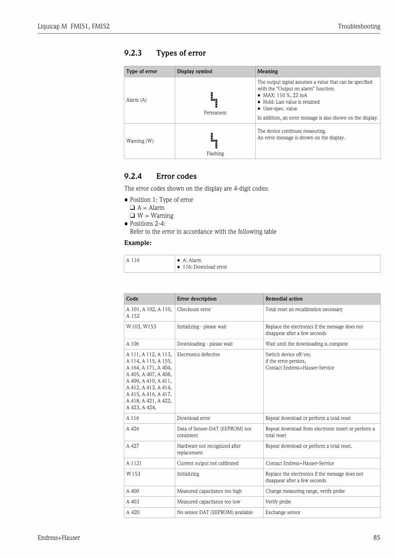
Liquicap M FMI51, FMI52 Troubleshooting
Endress+Hauser 85
9.2.3 Types of error
9.2.4 Error codes
The error codes shown on the display are 4-digit codes:
• Position 1: Type of error
❑ A = Alarm
❑ W = Warning
• Positions 2-4:
Refer to the error in accordance with the following table
Example:
Type of error Display symbol Meaning
Alarm (A)
Permanent
The output signal assumes a value that can be specified
with the "Output on alarm" function:
• MAX: 110 %, 22 mA
• Hold: Last value is retained
• User-spec. value
In addition, an error message is also shown on the display.
Warning (W)
Flashing
The device continues measuring.
An error message is shown on the display.
A 116 • A: Alarm
• 116: Download error
Code Error description Remedial action
A 101, A 102, A 110,
A 152
Checksum error Total reset an recalibration necessary
W 103, W153 Initializing - please wait Replace the electronics if the message does not
disappear after a few seconds
A 106 Downloading - please wait Wait until the downloading is complete
A 111, A 112, A 113,
A 114, A 115, A 155,
A 164, A 171, A 404,
A 405, A 407, A 408,
A 409, A 410, A 411,
A 412, A 413, A 414,
A 415, A 416, A 417,
A 418, A 421, A 422,
A 423, A 424,
Electronics defective Switch device off/on;
if the error persists,
Contact Endress+Hauser-Service
A 116 Download error Repeat download or perform a total reset
A 426 Data of Sensor-DAT (EEPROM) not
consistent
Repeat download from electronic insert or perform a
total reset
A 427 Hardware not recognized after
replacement
Repeat download or perform a total reset.
A 1121 Current output not calibrated Contact Endress+Hauser-Service
W 153 Initializing Replace the electronics if the message does not
disappear after a few seconds
A 400 Measured capacitance too high Change measuring range, verify probe
A 403 Measured capacitance too low Verify probe
A 420 No sensor DAT (EEPROM) available Exchange sensor
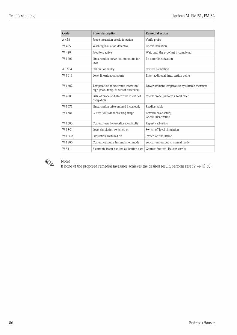
Troubleshooting Liquicap M FMI51, FMI52
86 Endress+Hauser
! Note!
If none of the proposed remedial measures achieves the desired result, perform reset 2 → ä 50.
A 428 Probe insulation break detection Verify probe
W 425 Warning insulation defective Check insulation
W 429 Prooftest active Wait until the prooftest is completed
W 1601 Linearization curve not monotone for
level
Re-enter linearization
A 1604 Calibration faulty Correct calibration
W 1611 Level linearization points Enter additional linearization points
W 1662 Temperature at electronic insert too
high (max. temp. at sensor exceeded)
Lower ambient temperature by suitable measures
W 430 Data of probe and electronic insert not
compatible
Check probe, perform a total reset
W 1671 Linearization table entered incorrectly Readjust table
W 1681 Current outside measuring range Perform basic setup;
Check linearization
W 1683 Current turn down calibration faulty Repeat calibration
W 1801 Level simulation switched on Switch off level simulation
W 1802 Simulation switched on Switch off simulation
W 1806 Current output is in simulation mode Set current output to normal mode
W 511 Electronic insert has lost calibration data Contact Endress+Hauser service
Code Error description Remedial action

Liquicap M FMI51, FMI52 Troubleshooting
Endress+Hauser 87
9.3 Possible measuring errors
9.4 Spare Parts
An overview of the spare parts for your device is available in the internet at www.endress.com.
To obtain information on the spare parts, proceed as follows:
1. Go to "www.endress.com" and select your country.
2. Click "Instruments".
3. Enter the product name into the "product name" field.
Error Remedial measures
Measured value is incorrect 1. Verify empty and full calibration.
2. Clean probe if necessary, verify probe
3. If necessary, alter better installation position of probe
(do not mount in filling curtain)
4. Check ground from process connection to tank wall.
Resistance measurement < 1 Ω)
5. Check probe insulation (resistance measurement) > 800 kΩ(only possible for conductive media)
BA298Fen080
If the surface is turbulent,
the measured value jumps
sporadically to higher levels
Increase output damping
7 5 3 1
8 6 4 2
7 5 3 1
8 6 4 2
F16 housing
Electronic insert FEI50H
1 = Guard2 = SDA_TXD3 = GND4 = GND EEPROM5 = GND6 = DVCC (3V)7 = Probe8 = SCL RXD
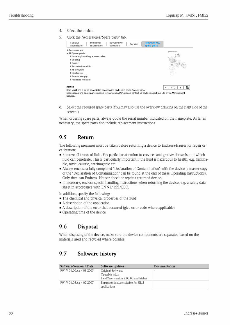
Troubleshooting Liquicap M FMI51, FMI52
88 Endress+Hauser
4. Select the device.
5. Click the "Accessories/Spare parts" tab.
6. Select the required spare parts (You may also use the overview drawing on the right side of the
screen.)
When ordering spare parts, always quote the serial number indicated on the nameplate. As far as
necessary, the spare parts also include replacement instructions.
9.5 Return
The following measures must be taken before returning a device to Endress+Hauser for repair or
calibration:
• Remove all traces of fluid. Pay particular attention to crevices and grooves for seals into which
fluid can penetrate. This is particularly important if the fluid is hazardous to health, e.g. flamma-
ble, toxic, caustic, carcinogenic etc.
• Always enclose a fully completed "Declaration of Contamination" with the device (a master copy
of the "Declaration of Contamination" can be found at the end of these Operating Instructions).
Only then can Endress+Hauser check or repair a returned device.
• If necessary, enclose special handling instructions when returning the device, e.g. a safety data
sheet in accordance with EN 91/155/EEC.
In addition, specify the following:
• The chemical and physical properties of the fluid
• A description of the application
• A description of the error that occurred (give error code where applicable)
• Operating time of the device
9.6 Disposal
When disposing of the device, make sure the device components are separated based on the
materials used and recycled where possible.
9.7 Software history
Software-Version / Date Software updates Documentation
FW: V 01.00.xx / 08.2005 Original-Software.
Operable with:
FieldCare, version 2.08.00 and higher
-
FW: V 01.03.xx / 02.2007 Expansion feature suitable for SIL 2
applications

Liquicap M FMI51, FMI52 Technical data
Endress+Hauser 89
10 Technical data
10.1 Technical data: probe
10.1.1 Capacitance values of the probe
• Basic capacitance: approx. 18 pF
10.1.2 Additional capacitance
• Mount the probe at a minimum distance of 50 mm from a conductive container wall:
Probe rod: approx. 1.3 pF/100 mm in air
Probe rope: approx. 1.0 pF/100 mm in air
• Fully insulated probe rod in water:
Approx. 38 pF/100 mm (16 mm rod)
Approx. 45 pF/100 mm (10 mm rod)
Approx. 50 pF/100 mm (22 mm rod)
• Insulated probe rope in water: approx. 19 pF/100 mm
• Rod probe with ground tube:
– Insulated probe rod: approx. 6.4 pF/100 mm in air
– Insulated probe rod: approx. 38 pF/100 mm in water (16 mm rod)
– Insulated probe rod: approx. 45 pF/100 mm in water (10 mm rod)
10.1.3 Probe lengths for continuous measurement in conductive liquids
• Rod probe (range 0 to 2000 pF at ≤ 4000 mm)
• Rope probe < 6 m (range 0 to 2000 pF)
• Rope probe > 6 m (range 0 to 4000 pF)
10.2 Input
10.2.1 Measured variable
Continuous measurement of change in capacitance between probe rod and container wall or ground
tube, depending on the level of a liquid.
Probe covered => high capacitance
Probe not covered => low capacitance
10.2.2 Measuring range
• Measuring frequency: 500 kHz
• Span: ΔC = 25 to 4000 pF recommended (2 to 4000 pF possible)
• Final capacitance: CE = max. 4000 pF
• Adjustable initial capacitance:
– CA = 0 to 2000 pF (< 6 m probe length)
– CA = 0 to 4000 pF (> 6 m probe length)

Technical data Liquicap M FMI51, FMI52
90 Endress+Hauser
10.2.3 Measuring condition
10.3 Output
10.3.1 Output signal
FEI50H (4 to 20mA/HART version 5.0)
3.8 to 20.5 mA with HART protocol
10.3.2 Signal on alarm
Fault diagnosis can be called up via:
• Local display: Red LED
• Local display showing:
– Error symbol
– Plain text display
• Current output: 22 mA
• Digital interface: HART status error message
10.3.3 Linearization
The Liquicap M linearization function enables conversion of the measured value into any desired
length or volume units. Linearization tables for volume calculation of horizontal cylindrical tanks
and spherical tanks are pre-programmed. Any other tables with up to 32 value pairs can be input
manually or semi-automatically.
10.4 Performance characteristics
10.4.1 Reference operating conditions
• Room temperature: +20 °C ±5 °C
• Span
– Standard measuring range: 5 to 2000 pF
– Extended measuring range: 5 to 4000 pF
– Span for reference: 5 to 4000 pF (corresponds to approx. 1 m probe length)
• Non-repeatability (reproducibility) as per DIN 61298-2: max. ±0.1 %
• Non-linearity for limit point setting (linearity) as per DIN 61298-2: max. ±0.25 %
• Measuring range L1 possible from the tip of
the probe to the process connection.
• Particularly suited for small containers.
Note!
When installing in a nozzle, use inactive
length (L3).
The 0 %, 100 % calibration can be inverted.
L00-FMI5xxxx-15-05-xx-xx-002
100 %
0 %
L3
L1

Liquicap M FMI51, FMI52 Technical data
Endress+Hauser 91
10.4.2 Maximum measured error
• Linearity: 0.5 %
• Reproducibility: 0.1 %
10.4.3 Influence of ambient temperature
< 0.06 %/10 K related to the full scale value
10.4.4 Switch-on behavior
14 s (stable measured value after switch-on procedure). Start-up in safe status (22mA).
10.4.5 Measured value reaction time
10.4.6 Output damping
τ = 1 s (factory setting) 0 to 60 s can be set.
The output damping affects the speed at which the display and the current output react to changes
in the level.
10.4.7 Accuracy of factory calibration
Operating mode: t1 ≤ 0.3 s
SIL operating mode: t1 ≤ 0.5 s
L00-FMI5xxxx-05-05-xx-xx-009
τ = Output damping
t1= Dead time
Probe length < 2 m Probe length > 2 m
Empty calibration (0 %), Full calibration (100 %) typically
≤ 5 mm
typically
≤ 2 %
Reference conditions for the factory calibration:
• Medium conductivity ≥ 100 μS/cm
• Minimum distance to tank wall = 250 mm
! Note!
In an installed state, recalibration is only
necessary if:
• The 0 % or the 100 % values have to be
adjusted specifically for customer
• The liquid is not conductive.
• The probe distance to the tank wall
is < 250 mm
L00-FMI5xxxx-15-05-xx-xx-002
63 %
100 %
t1τ
100 %
0 %
L3
L1

Technical data Liquicap M FMI51, FMI52
92 Endress+Hauser
10.4.8 Resolution
Analog in % (4 to 20 mA)
• FMI51, FMI52: 11 bit/2048 steps, 8 μA
• The resolution of the electronics can be directly converted to units of length of the probe FMI51
or FMI52. For example, active probe rod 1000 mm.
Resolution = 1000 mm/2048 = 0.48 mm
10.5 Operating conditions: Environment
10.5.1 Ambient temperature range
• –50 to +70 °C
• –40 to +70 °C (with F16 housing)
• Observe derating → ä 93
• If operating outdoors, use a protective cover! → ä 83.
10.5.2 Storage temperature
–50 to +85 °C
10.5.3 Climate class
DIN EN 60068-2-38/IEC 68-2-38: Z/AD check
10.5.4 Vibration resistance
DIN EN 60068-2-64/IEC 68-2-64: 20 Hz– 2000 Hz; 0.01 g2/Hz
10.5.5 Shock resistance
DIN EN 60068-2-27/IEC 68-2-27: 30g acceleration
10.5.6 Cleaning
Housing:
When cleaning, make sure that the cleaning agent used does not attack or corrode the housing
surface or seals.
Probe:
Depending on the application, buildup (contamination and soiling) can form on the probe rod. A
high degree of material buildup can affect the measurement result. If the medium tends to create a
high degree of buildup, regular cleaning is recommended. When hosing down or during mechanical
cleaning, it is important to make sure that the insulation of the probe rod is not damaged.
10.5.7 Degree of protection
IP66* IP67* IP68* NEMA4X*
*
Polyester housing F16 X X - X
Stainless steel housing F15 X X - X
Aluminum housing F17 X X - X
Aluminum housing F13
with gas-tight process seal
X – X*** X
Stainless steel housing F27
with gas-tight process seal
X X X*** X
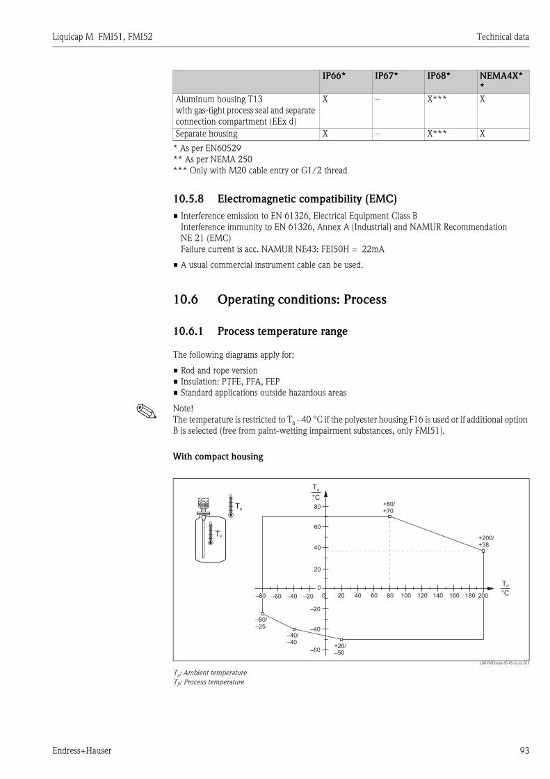
Liquicap M FMI51, FMI52 Technical data
Endress+Hauser 93
* As per EN60529
** As per NEMA 250
*** Only with M20 cable entry or G1/2 thread
10.5.8 Electromagnetic compatibility (EMC)
• Interference emission to EN 61326, Electrical Equipment Class B
Interference immunity to EN 61326, Annex A (Industrial) and NAMUR Recommendation
NE 21 (EMC)
Failure current is acc. NAMUR NE43: FEI50H = 22mA
• A usual commercial instrument cable can be used.
10.6 Operating conditions: Process
10.6.1 Process temperature range
The following diagrams apply for:
• Rod and rope version
• Insulation: PTFE, PFA, FEP
• Standard applications outside hazardous areas
! Note!
The temperature is restricted to Ta –40 °C if the polyester housing F16 is used or if additional option
B is selected (free from paint-wetting impairment substances, only FMI51).
With compact housing
L00-FMI5xxxx-05-05-xx-xx-013
Ta: Ambient temperature
TP: Process temperature
Aluminum housing T13
with gas-tight process seal and separate
connection compartment (EEx d)
X – X*** X
Separate housing X – X*** X
IP66* IP67* IP68* NEMA4X*
*
Ta
0
0
TP
–40 –20–60 80 120 160 180
80
60
40
20
–80
–80/–25
200
–60
–40
–20
20 40 60 100 140
–40/–40
+20/–50
+80/+70
+200/+38
TP
Ta
°C
°C
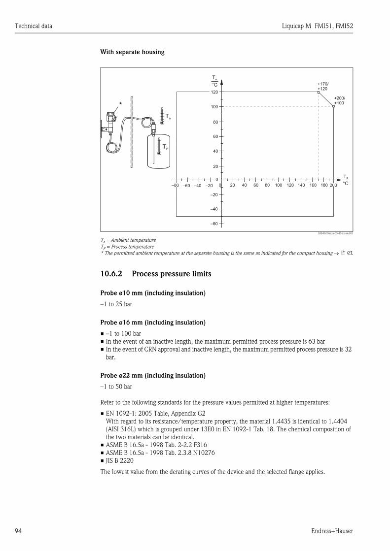
Technical data Liquicap M FMI51, FMI52
94 Endress+Hauser
With separate housing
L00-FMI5xxxx-05-05-xx-xx-011
Ta = Ambient temperature
TP = Process temperature
* The permitted ambient temperature at the separate housing is the same as indicated for the compact housing → ä 93.
10.6.2 Process pressure limits
Probe ø10 mm (including insulation)
–1 to 25 bar
Probe ø16 mm (including insulation)
• –1 to 100 bar
• In the event of an inactive length, the maximum permitted process pressure is 63 bar
• In the event of CRN approval and inactive length, the maximum permitted process pressure is 32
bar.
Probe ø22 mm (including insulation)
–1 to 50 bar
Refer to the following standards for the pressure values permitted at higher temperatures:
• EN 1092-1: 2005 Table, Appendix G2
With regard to its resistance/temperature property, the material 1.4435 is identical to 1.4404
(AISI 316L) which is grouped under 13E0 in EN 1092-1 Tab. 18. The chemical composition of
the two materials can be identical.
• ASME B 16.5a - 1998 Tab. 2-2.2 F316
• ASME B 16.5a - 1998 Tab. 2.3.8 N10276
• JIS B 2220
The lowest value from the derating curves of the device and the selected flange applies.
Ta
TP
0
0
TP
–40 –20–60 80 120 160 180
80
60
40
20
–80 200
–60
–40
–20
20 40 60 100 140
+200/+100
+170+120
/
°C
Ta
120
100
°C
*

Liquicap M FMI51, FMI52 Technical data
Endress+Hauser 95
10.6.3 Pressure and temperature derating
For process connections ½", ¾", 1", flanges < DN50, < ANSI 2", < JIS 10K (10 mm rod)
For process connections ¾", 1", flanges < DN50, < ANSI 2", < JIS 10K (16 mm rod)
Rod insulation: PTFE, PFA
Rope insulation: FEP, PFA
L00-FMI5xxxx-05-05-xx-xx-008
Pp : Process pressure
Tp : Process temperature
For process connections 1½", flanges ≥ DN50, ≥ ANSI 2", ≥ JIS 10K (16 mm rod)
Rod insulation: PTFE, PFA
Rope insulation: FEP, PFA
L00-FMI5xxxx-05-05-xx-xx-010
Pp : process pressure
Tp : process temperature
* For probes with an inactive length .
bar
Pp
0
0–40 –20–60 80 120 160 180
40
20
–80 +200/–1
20 40 60 100 140
+200/+2
+50/+25
TP
°C
bar
Pp
0
0–40 –20–60 80 120 160 180
60
40
80
20
–80 +200/–1
20 40 60 100 140
+200/+20
+80/+60
+40/+100
TP
°C
100
63 *

Technical data Liquicap M FMI51, FMI52
96 Endress+Hauser
With a fully insulated inactive length (22 mm rod):
L00-FMI5xxxx-05-05-xx-xx-012
Pp : Process pressure
Tp : Process temperature
10.7 Certificates and approvals
10.7.1 Other standards and guidelines
EN 60529
Degrees of protection by housing (IP code)
EN 61010
Protection measures for electrical equipment for measurement, control, regulation and laboratory
procedures
EN 61326
Interference emission (Class B equipment), interference immunity (Annex A - Industrial).
NAMUR
Association for Standards for Control and Regulation in the Chemical Industry
IEC 61508
Functional safety
10.7.2 Other approvals
• See also "Identification" on → ä 5 onwards.
• TSE Certificate of Suitability (FMI51)
The following applies to wetted device components:
– They do not contain any materials derived from animals.
– No additives or operating materials derived from animals are used in production or processing.
! Note!
The wetted device components are listed in the "Identification" section (→ ä 5).
• AD2000
The wetted material (316L) corresponds to AD2000 – W0/W2
10.8 Documentation
10.8.1 Technical Information
• Liquicap M FMI51, FMI52
TI00401F/00
bar
Pp
0
0–40 –20–60 80 120 160 180
60
40
20
–80 +200/–1
20 40 60 100 140
+200/+2
+50/+50
TP
°C

Liquicap M FMI51, FMI52 Technical data
Endress+Hauser 97
10.8.2 Certificates
ATEX safety instructions
• Liquicap M FMI51, FMI52
ATEX II 1/2 G EEx ia IIC/IIB T3 to T6, II 1/2 D IP65 T 85 °C
XA00327F/00/a3
• Liquicap M FMI51, FMI52
ATEX II 1/2 G EEx d [ia] IIC/IIB T3 to T6
XA00328F/00/a3
• Liquicap M FMI51, FMI52
Ga/Gb Ex ia IIC T6 to T3; Ex ia D 20 / Ex tD A21 IP65 T90°C
XA00423F/00/a3
NEPSI safety instructions
• Liquicap M FMI51, FMI52
Ex ia IIC/IIB T3 to T6
XA00417F/00/a3
• Liquicap M FMI51, FMI52
EEx d [ia] IIC/IIB T3 to T6
XA00418F/00/a3
• Liquicap M FMI51, FMI52
Ex nA II T3 to T6, Ex nC IIC T3 to T6
XA00430F/00/a3
Overfill protection DIBt (WHG)
• Liquicap M FMI51, FMI52
ZE00265F/00/de
Functional safety (SIL2)
• Liquicap M FMI51, FMI52
SD00198F/00/en
Control Drawings (CSA and FM)
• Liquicap M FMI51, FMI52
FM
ZD00220F/00/en
• Liquicap M FMI51, FMI52
CSA
ZD00221F/00/en
CRN registration
• CRN 0F1988.75
10.8.3 Patents
This product is protected by at least one of the following patents.
Further patents are pending.
• DE 103 22 279,
WO 2004 102 133,
US 2005 003 9528
• DE 203 13 695,
WO 2005 025 015
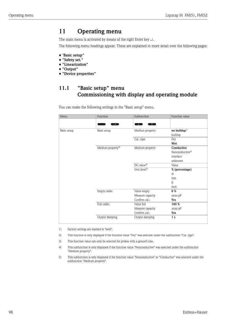
Operating menu Liquicap M FMI51, FMI52
98 Endress+Hauser
11 Operating menu
The main menu is activated by means of the right Enter key ↵.
The following menu headings appear. These are explained in more detail over the following pages:
• "Basic setup"
• "Safety set."
• "Linearization"
• "Output"
• "Device properties"
11.1 "Basic setup" menu
Commissioning with display and operating module
You can make the following settings in the "Basic setup" menu.
Menu Function Subfunction Function value
Basic setup Basic setup Medium property no buildup1)
1) Factory settings are marked in "bold".
buildup
Cal. type Dry
Wet
Medium property2)
2) This function is only displayed if the function value "Dry" was selected under the subfunction "Cal. type".
Medium property Conductive
Nonconductive3)
3) This function value can only be selected for probes with a ground tube.
interface
unknown
DC value4)
4) This subfunction is only displayed if the function value "Nonconductive" was selected under the subfunction
"Medium property".
Value
Unit level5)
5) This subfunction is only displayed if the function value "Nonconductive" or "Conductive" was selected under the
subfunction "Medium property".
% (percentage)
m
mm
ft
inch
Empty calibr. Value empty 0 %
Measure capacity xxxx pF
Confirm cal.: Yes
Full calibr. Value full 100 %
Measure capacity xxxx pF
Confirm cal.: Yes
Output damping Output damping 1 s
↑ ↑↑
↑

Liquicap M FMI51, FMI52 Operating menu
Endress+Hauser 99
11.2 "Safety setting" menu
You can make the following settings in the "Safety settings" menu.
Menu Function Subfunction Function value
Safety settings Safety settings I Code 1001)
1) Factory settings are marked in "bold".
Status Unlocked
Locked
Safety settings II Operating mode Standard
SIL/WHG
Output damping 1 s
Output 1 MAX
Parameter okay no
Yes
Safety settings III Cap. empty x,xx pF
Value empty x,xxx %
Cap. full 2000.00 pF
Value full 100.000 %
Parameter okay no
Yes
Operating mode Operating mode Standard
SIL/WHG
SIL op. mode2)
2) This subfunction is only displayed if the "SIL/WHG" option was selected under the "Operating mode" subfunction.
Unlocked
Locked
Status Unlocked
Locked
Output on alarm Output Max
Hold
User-spec.
Output value3)
3) This subfunction is only displayed if the "User-specific" option was selected under the "Output" subfunction.
xx.xx mA
Proof test Proof test Off
On
↑ ↑↑
↑
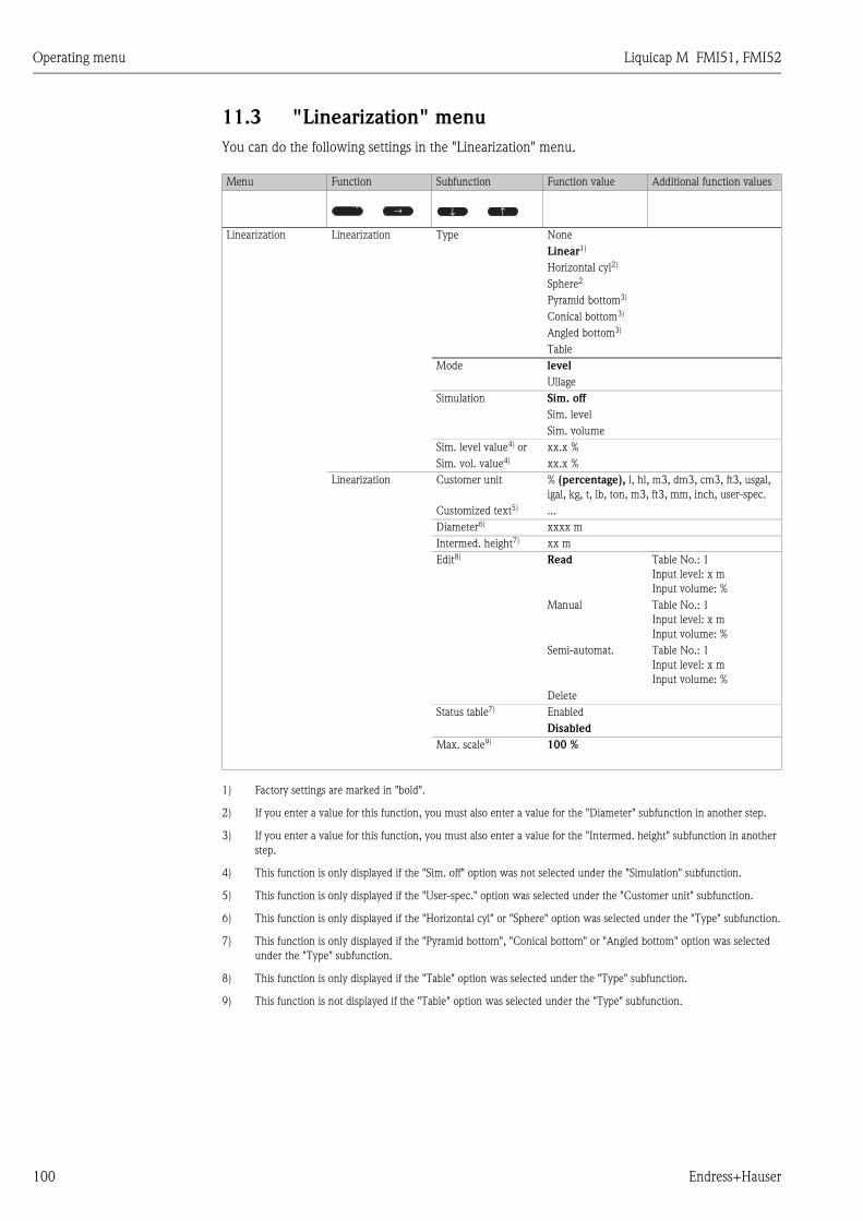
Operating menu Liquicap M FMI51, FMI52
100 Endress+Hauser
11.3 "Linearization" menu
You can do the following settings in the "Linearization" menu.
Menu Function Subfunction Function value Additional function values
Linearization Linearization Type None
Linear1)
1) Factory settings are marked in "bold".
Horizontal cyl2)
2) If you enter a value for this function, you must also enter a value for the "Diameter" subfunction in another step.
Sphere2
Pyramid bottom3)
3) If you enter a value for this function, you must also enter a value for the "Intermed. height" subfunction in another
step.
Conical bottom3)
Angled bottom3)
Table
Mode level
Ullage
Simulation Sim. off
Sim. level
Sim. volume
Sim. level value4) or
4) This function is only displayed if the "Sim. off" option was not selected under the "Simulation" subfunction.
xx.x %
Sim. vol. value4) xx.x %
Linearization Customer unit % (percentage), l, hl, m3, dm3, cm3, ft3, usgal,
igal, kg, t, lb, ton, m3, ft3, mm, inch, user-spec.
Customized text5)
5) This function is only displayed if the "User-spec." option was selected under the "Customer unit" subfunction.
...
Diameter6)
6) This function is only displayed if the "Horizontal cyl" or "Sphere" option was selected under the "Type" subfunction.
xxxx m
Intermed. height7)
7) This function is only displayed if the "Pyramid bottom", "Conical bottom" or "Angled bottom" option was selected
under the "Type" subfunction.
xx m
Edit8)
8) This function is only displayed if the "Table" option was selected under the "Type" subfunction.
Read Table No.: 1
Input level: x m
Input volume: %
Manual Table No.: 1
Input level: x m
Input volume: %
Semi-automat. Table No.: 1
Input level: x m
Input volume: %
Delete
Status table7) Enabled
Disabled
Max. scale9)
9) This function is not displayed if the "Table" option was selected under the "Type" subfunction.
100 %
↑ ↑↑
↑
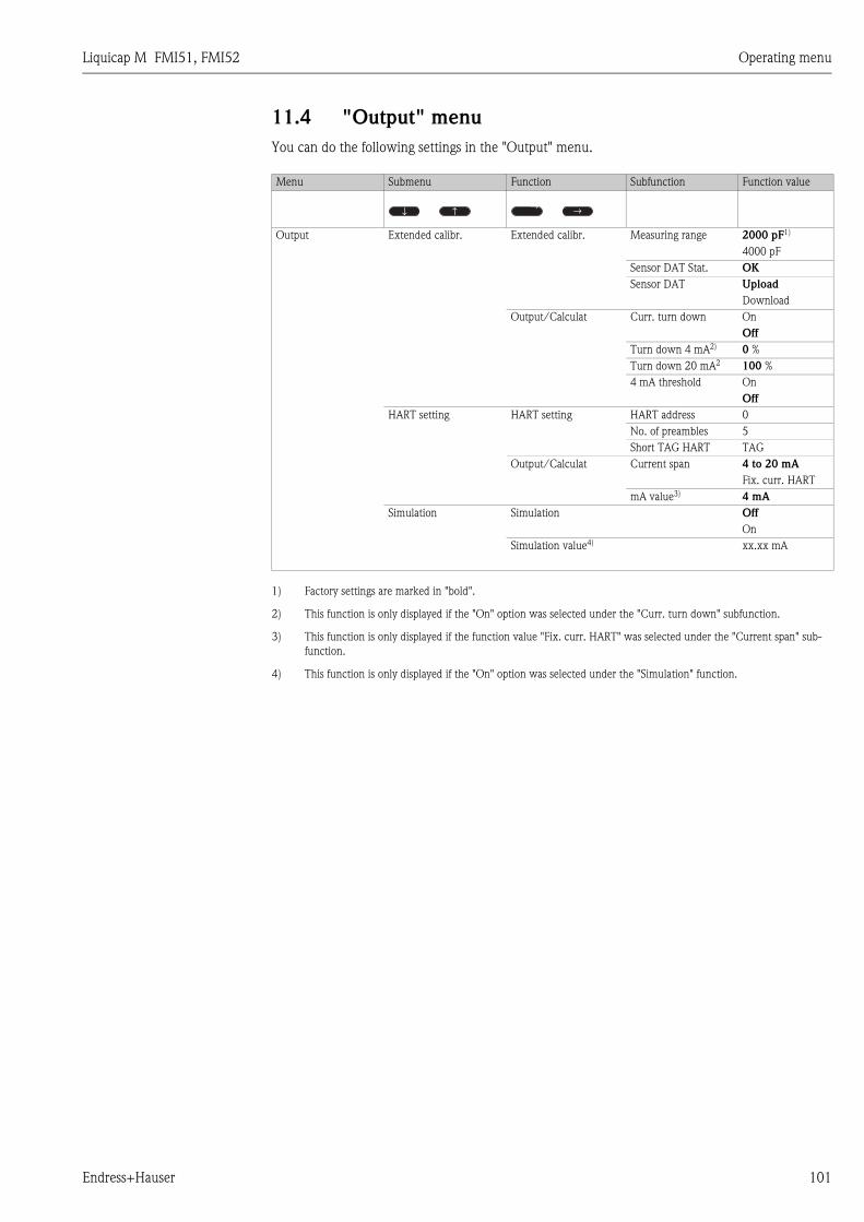
Liquicap M FMI51, FMI52 Operating menu
Endress+Hauser 101
11.4 "Output" menu
You can do the following settings in the "Output" menu.
Menu Submenu Function Subfunction Function value
Output Extended calibr. Extended calibr. Measuring range 2000 pF1)
1) Factory settings are marked in "bold".
4000 pF
Sensor DAT Stat. OK
Sensor DAT Upload
Download
Output/Calculat Curr. turn down On
Off
Turn down 4 mA2)
2) This function is only displayed if the "On" option was selected under the "Curr. turn down" subfunction.
0 %
Turn down 20 mA2 100 %
4 mA threshold On
Off
HART setting HART setting HART address 0
No. of preambles 5
Short TAG HART TAG
Output/Calculat Current span 4 to 20 mA
Fix. curr. HART
mA value3)
3) This function is only displayed if the function value "Fix. curr. HART" was selected under the "Current span" sub-
function.
4 mA
Simulation Simulation Off
On
Simulation value4)
4) This function is only displayed if the "On" option was selected under the "Simulation" function.
xx.xx mA
↑↑
↑ ↑

Operating menu Liquicap M FMI51, FMI52
102 Endress+Hauser
11.5 "Device properties" menu
You can do the following settings in the "Device properties" menu.
Menu Submenu Function Subfunction Function value
Device properties Display Language English
Deutsch
Francais
Espanol
Italiano
Nederlands
Display format Format Decimal
ft-in-1/16"
No of decimals x
x.x
x.xx
x.xxx
Sep. character . (dot)
,
Back to home 900 s
Diagnostics Actual error Actual error 1 ....
Actual error 2 ....
Actual error 3 ....
Last error reset errorlist Keep
Delete
Last error 2 ...
Last error 3 ...
Password/reset Reset 12345
Status Unlocked
Electronic temp. Electronic temp. xx.x °C
Max. temp. xx.x °C
Min. temp. xx.x °C
Temperature unit °C
°F
K
Min/Max temp. Keep
Delete
Reset Min.
Reset Max.
Measure capacity Measure capacity xxxx.xx pF
Max. capacity val xxxx.xx pF
Min. capacity val xxxx.xx pF
Min/Max capacity Keep
Delete
Reset Min.
Reset Max.
System parameters Device information I Device designation Liquicap-FMI5x
Serial No. ...
EC Serial No. xxxxxxxxxxx
Device marking FMI51-OrderCode
Device information Dev. rev x
Software version V01.xx.xx.xxx
DD version xx
Device information III Working hour xxxxx h
Current run time 000d00h00m
Probe length Probe length xxx mm
Sensitivity 0.0
↑↑
↑ ↑

Liquicap M FMI51, FMI52 Index
Endress+Hauser 103
Index
Numerics4 mA threshold . . . . . . . . . . . . . . . . . . . . . . . . . . . . . . . . . 71
AAccessories . . . . . . . . . . . . . . . . . . . . . . . . . . . . . . . . . . . . 84
Actual error. . . . . . . . . . . . . . . . . . . . . . . . . . . . . . . . . . . . 74
Aligning the housing . . . . . . . . . . . . . . . . . . . . . . . . . . . . . 25
BBasic setup . . . . . . . . . . . . . . . . . . . . . . . . . . . . . . 48, 53, 55
CCable specification . . . . . . . . . . . . . . . . . . . . . . . . . . . . . . 27
Cal. type . . . . . . . . . . . . . . . . . . . . . . . . . . . . . . . . . . . . . . 55
Calibration error . . . . . . . . . . . . . . . . . . . . . . . . . . . . . . . . 88
Cap. empty . . . . . . . . . . . . . . . . . . . . . . . . . . . . . . . . . 57, 60
Cap. full . . . . . . . . . . . . . . . . . . . . . . . . . . . . . . . . . . . . . . 60
CapCalc . . . . . . . . . . . . . . . . . . . . . . . . . . . . . . . . . . . 56, 79
Carrying out empty calibration . . . . . . . . . . . . . . . . . . . . . 49
CE mark . . . . . . . . . . . . . . . . . . . . . . . . . . . . . . . . . . . . . . 12
Certificates and approvals . . . . . . . . . . . . . . . . . . . . . . . . . 97
Code. . . . . . . . . . . . . . . . . . . . . . . . . . . . . . . . . . . . . . . . . 59
Commissioning . . . . . . . . . . . . . . . . . . . . . . . . . . . . . . . . . 48
Commubox. . . . . . . . . . . . . . . . . . . . . . . . . . . . . . . . . . . . 84
Commubox FXA191/195 HART . . . . . . . . . . . . . . . . . . . . 84
Confirm cal.
. . . . . . . . . . . . . . . . . . . . . . . . . . . . . . . . . . . . . . . . . . 56
Connection . . . . . . . . . . . . . . . . . . . . . . . . . . . . . . . . . 28, 31
Curr. turn down . . . . . . . . . . . . . . . . . . . . . . . . . . . . . . . . 70
Current run time. . . . . . . . . . . . . . . . . . . . . . . . . . . . . . . . 76
Current span . . . . . . . . . . . . . . . . . . . . . . . . . . . . . . . . . . . 71
Customer unit. . . . . . . . . . . . . . . . . . . . . . . . . . . . . . . . . . 66
Customized text . . . . . . . . . . . . . . . . . . . . . . . . . . . . . . . . 67
DDC value . . . . . . . . . . . . . . . . . . . . . . . . . . . . . . . . . . . . . 55
DD version . . . . . . . . . . . . . . . . . . . . . . . . . . . . . . . . . . . . 76
Declaration of Conformity . . . . . . . . . . . . . . . . . . . . . . . . . 12
Declaration of Contamination . . . . . . . . . . . . . . . . . . . . . . 89
Designated use . . . . . . . . . . . . . . . . . . . . . . . . . . . . . . . . . . 3
Dev. rev . . . . . . . . . . . . . . . . . . . . . . . . . . . . . . . . . . . . . . 76
Device designation . . . . . . . . . . . . . . . . . . . . . . . . . . . . . . 76
Device information . . . . . . . . . . . . . . . . . . . . . . . . . . . . . . 76
Device marking. . . . . . . . . . . . . . . . . . . . . . . . . . . . . . . . . 76
Device properties . . . . . . . . . . . . . . . . . . . . . . . . . . . . 53, 73
Diagnostics . . . . . . . . . . . . . . . . . . . . . . . . . . . . . . . . . . . . 74
Diameter. . . . . . . . . . . . . . . . . . . . . . . . . . . . . . . . . . . . . . 67
Display and operating elements (FEI50H) . . . . . . . . . . . . . 33
Display and operating module . . . . . . . . . . . . . . . . . . . 34, 53
Display format. . . . . . . . . . . . . . . . . . . . . . . . . . . . . . . . . . 74
Display symbols. . . . . . . . . . . . . . . . . . . . . . . . . . . . . . . . . 34
Disposal . . . . . . . . . . . . . . . . . . . . . . . . . . . . . . . . . . . . . . 89
Download/upload sensor DAT . . . . . . . . . . . . . . . . . . . . . 52
Dry calibration . . . . . . . . . . . . . . . . . . . . . . . . . . . . . . . . . 53
Dry calibration for interface measurement . . . . . . . . . . . . . 80
EEC Serial No.. . . . . . . . . . . . . . . . . . . . . . . . . . . . . . . . . . . 76
Edit . . . . . . . . . . . . . . . . . . . . . . . . . . . . . . . . . . . . . . . . . . 67
Editing functions with the picklist . . . . . . . . . . . . . . . . . . . 41
Editing numeric functions . . . . . . . . . . . . . . . . . . . . . . . . . 42
Electrical symbols . . . . . . . . . . . . . . . . . . . . . . . . . . . . . . . . 4
Electromagnetic compatibility (EMC) . . . . . . . . . . . . . . . . . 27
Electronic temp. . . . . . . . . . . . . . . . . . . . . . . . . . . . . . . . . 75
Empty calibr. . . . . . . . . . . . . . . . . . . . . . . . . . . . . . . . . . . . 56
Empty calibration ("Dry" operating mode) . . . . . . . . . . . . . 57
Error codes . . . . . . . . . . . . . . . . . . . . . . . . . . . . . . . . . . . . 86
Error signal . . . . . . . . . . . . . . . . . . . . . . . . . . . . . . . . . . . . 85
Ex area . . . . . . . . . . . . . . . . . . . . . . . . . . . . . . . . . . . . . . . . 3
Extended calibr. . . . . . . . . . . . . . . . . . . . . . . . . . . . . . . . . 69
External cleaning. . . . . . . . . . . . . . . . . . . . . . . . . . . . . . . . 83
FFieldbus connector . . . . . . . . . . . . . . . . . . . . . . . . . . . . . . 28
Full calibr. . . . . . . . . . . . . . . . . . . . . . . . . . . . . . . . . . . . . . 56
Full calibration ("Dry" operating mode). . . . . . . . . . . . . . . . 57
Function and subfunction . . . . . . . . . . . . . . . . . . . . . . . . . 40
Function switch. . . . . . . . . . . . . . . . . . . . . . . . . . . . . . . . . 49
GGreen LED flashing . . . . . . . . . . . . . . . . . . . . . . . . . . . . . . 85
Ground tube . . . . . . . . . . . . . . . . . . . . . . . . . . . . . . . . . . . 17
HHandheld terminal DXR375. . . . . . . . . . . . . . . . . . . . . . . . 47
HART . . . . . . . . . . . . . . . . . . . . . . . . . . . . . . . . . . . . . . . . 31
HART - connecting with other supply units . . . . . . . . . . . . 31
HART address . . . . . . . . . . . . . . . . . . . . . . . . . . . . . . . . . . 71
HART handheld terminal DXR 375 . . . . . . . . . . . . . . . . . . 47
HART settings . . . . . . . . . . . . . . . . . . . . . . . . . . . . . . . . . . 71
IInactive length. . . . . . . . . . . . . . . . . . . . . . . . . . . . . . . . . . 17
Incoming acceptance . . . . . . . . . . . . . . . . . . . . . . . . . . . . . 13
Initial commissioning. . . . . . . . . . . . . . . . . . . . . . . . . . . . . 53
Installation . . . . . . . . . . . . . . . . . . . . . . . . . . . . . . . . . . . . 13
Installation and function check . . . . . . . . . . . . . . . . . . . . . 48
Intermed. height . . . . . . . . . . . . . . . . . . . . . . . . . . . . . . . . 67
KKey combinations . . . . . . . . . . . . . . . . . . . . . . . . . . . . . . . 35
Key locking . . . . . . . . . . . . . . . . . . . . . . . . . . . . . . . . . . . . 45
Key unlocking . . . . . . . . . . . . . . . . . . . . . . . . . . . . . . . . . . 45
Keys (softkey operation) . . . . . . . . . . . . . . . . . . . . . . . . . . . 35
LLanguage. . . . . . . . . . . . . . . . . . . . . . . . . . . . . . . . . . . . . . 74
Last error. . . . . . . . . . . . . . . . . . . . . . . . . . . . . . . . . . . . . . 74
Last errors . . . . . . . . . . . . . . . . . . . . . . . . . . . . . . . . . . . . . 85
Launching menus . . . . . . . . . . . . . . . . . . . . . . . . . . . . . . . 38
Linearization . . . . . . . . . . . . . . . . . . . . . . . . . . . . . 53, 63, 66
Locking . . . . . . . . . . . . . . . . . . . . . . . . . . . . . . . . . . . . . . . 45
Liquicap M FMI51, FMI52 Index
104 Endress+Hauser
MMaintenance . . . . . . . . . . . . . . . . . . . . . . . . . . . . . . . . . . . 83
Marine approval (GL) . . . . . . . . . . . . . . . . . . . . . . . . . . . . 15
Max. capacity . . . . . . . . . . . . . . . . . . . . . . . . . . . . . . . . . . 75
Max. scale. . . . . . . . . . . . . . . . . . . . . . . . . . . . . . . . . . . . . 68
Max. temp. . . . . . . . . . . . . . . . . . . . . . . . . . . . . . . . . . . . . 75
Measure capacity. . . . . . . . . . . . . . . . . . . . . . . . . . . . . 56, 75
Measured value display . . . . . . . . . . . . . . . . . . . . . . . . . . . 44
Measuring condition . . . . . . . . . . . . . . . . . . . . . . . . . . . . . 15
Measuring modes . . . . . . . . . . . . . . . . . . . . . . . . . . . . . . . 49
Measuring range . . . . . . . . . . . . . . . . . . . . . . . . . . 26, 51, 69
Medium . . . . . . . . . . . . . . . . . . . . . . . . . . . . . . . . . . . 49, 55
Medium property . . . . . . . . . . . . . . . . . . . . . . . . . . . . 49, 55
Menu-guided commissioning. . . . . . . . . . . . . . . . . . . . . . . 46
Min. capacity . . . . . . . . . . . . . . . . . . . . . . . . . . . . . . . . . . 75
Min. temp. . . . . . . . . . . . . . . . . . . . . . . . . . . . . . . . . . . . . 75
Min/Max capacity. . . . . . . . . . . . . . . . . . . . . . . . . . . . . . . 75
Min/Max temp. . . . . . . . . . . . . . . . . . . . . . . . . . . . . . . . . 75
Mode . . . . . . . . . . . . . . . . . . . . . . . . . . . . . . . . . . . . . . . . 66
NNameplate. . . . . . . . . . . . . . . . . . . . . . . . . . . . . . . . . . . . . . 5
Navigating in the menu . . . . . . . . . . . . . . . . . . . . . . . . . . . 37
Next highest . . . . . . . . . . . . . . . . . . . . . . . . . . . . . . . . . . . 45
No. of decimals . . . . . . . . . . . . . . . . . . . . . . . . . . . . . . . . . 74
No. of preambles . . . . . . . . . . . . . . . . . . . . . . . . . . . . . . . . 71
Notes on safety conventions and icons . . . . . . . . . . . . . . . . . 4
OOperating menu . . . . . . . . . . . . . . . . . . . . . . . . . . . . . . . . 36
Operating menu (overview) . . . . . . . . . . . . . . . . . . . . . . . . 99
Operating mode . . . . . . . . . . . . . . . . . . . . . . . . . . . . . 60–61
Operating options . . . . . . . . . . . . . . . . . . . . . . . . . . . . . . . 32
Operation . . . . . . . . . . . . . . . . . . . . . . . . . . . . . . . . . . . . . 77
Operational safety . . . . . . . . . . . . . . . . . . . . . . . . . . . . . . . . 3
Orientation . . . . . . . . . . . . . . . . . . . . . . . . . . . . . . . . . . . . 14
Output . . . . . . . . . . . . . . . . . . . . . . . . . . . . . . . . . . . . 53, 69
Output 1 . . . . . . . . . . . . . . . . . . . . . . . . . . . . . . . . . . . . . . 60
Output damping . . . . . . . . . . . . . . . . . . . . . . . . . . 58, 60–61
Output on alarm . . . . . . . . . . . . . . . . . . . . . . . . . . . . . . . . 62
Output value . . . . . . . . . . . . . . . . . . . . . . . . . . . . . . . . . . . 62
Output/Calculat . . . . . . . . . . . . . . . . . . . . . . . . . . . . . . . . 71
Output/calculat. . . . . . . . . . . . . . . . . . . . . . . . . . . . . . . . . 70
PParameter okay . . . . . . . . . . . . . . . . . . . . . . . . . . . . . . 60–61
Password/reset . . . . . . . . . . . . . . . . . . . . . . . . . . . . . . . . . 74
Performance characteristics . . . . . . . . . . . . . . . . . . . . . . . . 91
Pipe mounting. . . . . . . . . . . . . . . . . . . . . . . . . . . . . . . . . . 23
Planning instructions . . . . . . . . . . . . . . . . . . . . . . . . . . . . . 14
Post-connection check. . . . . . . . . . . . . . . . . . . . . . . . . . . . 31
Post-installation check . . . . . . . . . . . . . . . . . . . . . . . . . . . . 26
Potential equalization . . . . . . . . . . . . . . . . . . . . . . . . . . . . 27
Probe length . . . . . . . . . . . . . . . . . . . . . . . . . . . . . . . . . . . 76
Proof test. . . . . . . . . . . . . . . . . . . . . . . . . . . . . . . . . . . 51, 62
Protective cover . . . . . . . . . . . . . . . . . . . . . . . . . . . . . . . . 84
RRed LED flashing . . . . . . . . . . . . . . . . . . . . . . . . . . . . . . . . 85
Repair . . . . . . . . . . . . . . . . . . . . . . . . . . . . . . . . . . . . . . . . 83
Repairing Ex-certified devices . . . . . . . . . . . . . . . . . . . . . . 83
Replacement. . . . . . . . . . . . . . . . . . . . . . . . . . . . . . . . . . . 83
Reset . . . . . . . . . . . . . . . . . . . . . . . . . . . . . . . . . . 45, 51, 75
Restore factory settings . . . . . . . . . . . . . . . . . . . . . . . . . . . 51
Return . . . . . . . . . . . . . . . . . . . . . . . . . . . . . . . . . . . . . . . 89
Rod probes . . . . . . . . . . . . . . . . . . . . . . . . . . . . . . . . . . . . 16
Rope probes . . . . . . . . . . . . . . . . . . . . . . . . . . . . . . . . . . . 19
Rotating the housing . . . . . . . . . . . . . . . . . . . . . . . . . . . . . 25
SSafety instructions. . . . . . . . . . . . . . . . . . . . . . . . . . . . . . 3–4
Safety setting . . . . . . . . . . . . . . . . . . . . . . . . . . . . . . . 53, 59
Safety settings. . . . . . . . . . . . . . . . . . . . . . . . . . . . . . . . . . 59
Sealing (housing) . . . . . . . . . . . . . . . . . . . . . . . . . . . . . . . 26
Seals. . . . . . . . . . . . . . . . . . . . . . . . . . . . . . . . . . . . . . . . . 83
Self-test . . . . . . . . . . . . . . . . . . . . . . . . . . . . . . . . . . . . . . 51
Sensor DAT . . . . . . . . . . . . . . . . . . . . . . . . . . . . . . . . . . . 70
Sensor DAT stat.. . . . . . . . . . . . . . . . . . . . . . . . . . . . . . . . 70
Sep. character. . . . . . . . . . . . . . . . . . . . . . . . . . . . . . . . . . 74
Separate housing. . . . . . . . . . . . . . . . . . . . . . . . . . . . . . . . 21
Separate housing (shortening the connecting cable) . . . . . . 23
Serial No. . . . . . . . . . . . . . . . . . . . . . . . . . . . . . . . . . . . . . 76
Short TAG HART . . . . . . . . . . . . . . . . . . . . . . . . . . . . . . . 71
Shortening set. . . . . . . . . . . . . . . . . . . . . . . . . . . . . . . . . . 84
Shortening the rope . . . . . . . . . . . . . . . . . . . . . . . . . . . . . 20
SIL operating mode. . . . . . . . . . . . . . . . . . . . . . . . . . . . . . 61
Sim. level value . . . . . . . . . . . . . . . . . . . . . . . . . . . . . . . . 66
Sim. vol. value . . . . . . . . . . . . . . . . . . . . . . . . . . . . . . . . . 66
Simulation . . . . . . . . . . . . . . . . . . . . . . . . . . . . . . . . . 66, 72
Simulation value . . . . . . . . . . . . . . . . . . . . . . . . . . . . . . . . 72
Software history . . . . . . . . . . . . . . . . . . . . . . . . . . . . . . . . 89
Software locking . . . . . . . . . . . . . . . . . . . . . . . . . . . . . . . . 45
Software version . . . . . . . . . . . . . . . . . . . . . . . . . . . . . . . . 76
Spare Parts . . . . . . . . . . . . . . . . . . . . . . . . . . . . . . . . . . . . 88
Status . . . . . . . . . . . . . . . . . . . . . . . . . . . . . . . . . . . . . 60–61
Status table. . . . . . . . . . . . . . . . . . . . . . . . . . . . . . . . . . . . 68
Storage . . . . . . . . . . . . . . . . . . . . . . . . . . . . . . . . . . . . . . . 13
Storage temperature . . . . . . . . . . . . . . . . . . . . . . . . . . . . . 13
Submenus . . . . . . . . . . . . . . . . . . . . . . . . . . . . . . . . . . . . 39
System parameters . . . . . . . . . . . . . . . . . . . . . . . . . . . . . . 76
TTable editor . . . . . . . . . . . . . . . . . . . . . . . . . . . . . . . . . . . 67
Technical data . . . . . . . . . . . . . . . . . . . . . . . . . . . . . . . . . 90
Temperature unit . . . . . . . . . . . . . . . . . . . . . . . . . . . . . . . 75
Tensioning weight with tension . . . . . . . . . . . . . . . . . . . . 20
ToF Tool. . . . . . . . . . . . . . . . . . . . . . . . . . . . . . . . . . . 31, 46
ToF Tool - FieldTool Package . . . . . . . . . . . . . . . . . . . . . . 46
Troubleshooting . . . . . . . . . . . . . . . . . . . . . . . . . . . . . . . . 85
Troubleshooting instructions . . . . . . . . . . . . . . . . . . . . . . . 85
Turn down 20 mA . . . . . . . . . . . . . . . . . . . . . . . . . . . . . . 70
Turn down 4 mA . . . . . . . . . . . . . . . . . . . . . . . . . . . . . . . 70
Type. . . . . . . . . . . . . . . . . . . . . . . . . . . . . . . . . . . . . . . . . 64
Type of protection. . . . . . . . . . . . . . . . . . . . . . . . . . . . . . . . 4
Types of error . . . . . . . . . . . . . . . . . . . . . . . . . . . . . . . . . . 86
UUnit level . . . . . . . . . . . . . . . . . . . . . . . . . . . . . . . . . . . . . 56

Liquicap M FMI51, FMI52 Index
Endress+Hauser 105
VValue empty . . . . . . . . . . . . . . . . . . . . . . . . . . . . . 56–57, 60
Value full . . . . . . . . . . . . . . . . . . . . . . . . . . . . . . . . . . 56, 60
WWall bracket . . . . . . . . . . . . . . . . . . . . . . . . . . . . . . . . . . . 22
Wall mounting . . . . . . . . . . . . . . . . . . . . . . . . . . . . . . . . . 22
Wet calibration
. . . . . . . . . . . . . . . . . . . . . . . . . . . . . . . . . . . . . . . . . . 53
Wiring . . . . . . . . . . . . . . . . . . . . . . . . . . . . . . . . . . . . . . . 27
Working hour . . . . . . . . . . . . . . . . . . . . . . . . . . . . . . . . . . 76

Liquicap M FMI51, FMI52 Index
106 Endress+Hauser

P/S
F/K
onta
XIV
Because of legal regulations and for the safety of our employees and operating equipment, we need the "Declaration of Hazardous Materialand De-Contamination", with your signature, before your order can be handled. Please make absolutely sure to attach it to the outside of thepackaging.Aufgrund der gesetzlichen Vorschriften und zum Schutz unserer Mitarbeiter und Betriebseinrichtungen, benötigen wir die unterschriebene"Erklärung zur Kontamination und Reinigung", bevor Ihr Auftrag bearbeitet werden kann. Bringen Sie diese unbedingt außen an derVerpackung an.
Serial number
Seriennummer ________________________Type of instrument / sensor
Geräte-/Sensortyp ____________________________________________
Process data/Prozessdaten Temperature _____ [°F] [°C]
Conductivity / ________
_____
Leitfähigkeit
/
[μS/cm]
Temperatur Pressure _____ [psi] [ Pa ]
Viscosity _____ [cp] [mm /s]
_____
_____
/
/
Druck
Viskosität2
corrosiveätzend
harmlessunbedenklich
other *sonstiges*
toxicgiftig
Processmedium
IdentificationCAS No.
flammableentzündlich
harmful/irritant
gesundheits-schädlich/
reizend
Medium /concentrationMedium /Konzentration
Returned partcleaned with
Medium forprocess cleaning
Medium and warnings
Warnhinweise zum Medium
* explosive; oxidising; dangerous for the environment; biological risk; radioactive* explosiv; brandfördernd; umweltgefährlich; biogefährlich; radioaktiv
Please tick should one of the above be applicable, include safety data sheet and, if necessary, special handling instructions.Zutreffendes ankreuzen; trifft einer der Warnhinweise zu, Sicherheitsdatenblatt und ggf. spezielle Handhabungsvorschriften beilegen.
Description of failure / Fehlerbeschreibung __________________________________________________________________________
______________________________________________________________________________________________________________
______________________________________________________________________________________________________________
“We hereby certify that this declaration is filled out truthfully and completely to the best of our knowledge.We further certify that the returnedparts have been carefully cleaned. To the best of our knowledge they are free of any residues in dangerous quantities.”“Wir bestätigenw
bestätigen, die vorliegende Erklärung nach unserem besten Wissen wahrheitsgetreu und vollständig ausgefüllt zu haben. Wireiter, dass die zurückgesandten Teile sorgfältig gereinigt wurden und nach unserem besten Wissen frei von Rückständen in gefahrbringen-
der Menge sind.”
(place, date / Ort, Datum)
Company data /Angaben zum Absender
Company / ________________________________
_________________________________________________
Address /
_________________________________________________
_________________________________________________
Firma ___
Adresse
Phone number of contact person /
____________________________________________
Fax / E-Mail ____________________________________________
Your order No. / ____________________________
Telefon-Nr. Ansprechpartner:
Ihre Auftragsnr.
Medium zurEndreinigung
Medium zurProzessreinigung
Medium imProzess
Used as SIL device in a Safety Instrumented System / Einsatz als SIL Gerät in Schutzeinrichtungen
RA No.
Erklärung zur Kontamination und ReinigungDeclaration of Hazardous Material and De-Contamination
Please reference the Return Authorization Number (RA#), obtained from Endress+Hauser, on all paperwork and mark the RA#clearly on the outside of the box. If this procedure is not followed, it may result in the refusal of the package at our facility.
Bitte geben Sie die von E+H mitgeteilte Rücklieferungsnummer (RA#) auf allen Lieferpapieren an und vermerken Sie dieseauch außen auf der Verpackung. Nichtbeachtung dieser Anweisung führt zur Ablehnung ihrer Lieferung.
Name, dept./Abt. (please print / )bitte Druckschrift Signature / Unterschrift

www.endress.com/worldwide
BA00298F/00/en/13.10
71123554
CCS/FM+SGML 6.0 71123554