Embed Size (px)
Citation preview

Link Layer: MAC
Ilam University
Dr. Mozafar Bag-Mohammadi
Contents
Multiple Access Protocols Local Area Network (LAN) Ethernet Hubs, Bridges, and Switches
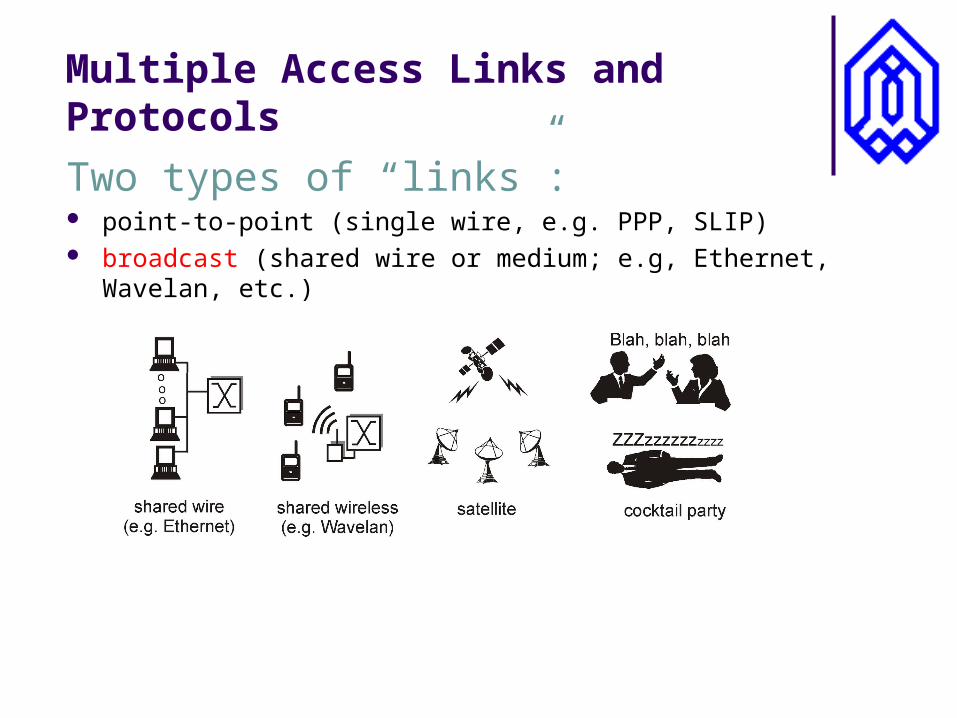
Multiple Access Links and Protocols
Two types of “links”: point-to-point (single wire, e.g. PPP, SLIP) broadcast (shared wire or medium; e.g, Ethernet, Wavelan, etc.)
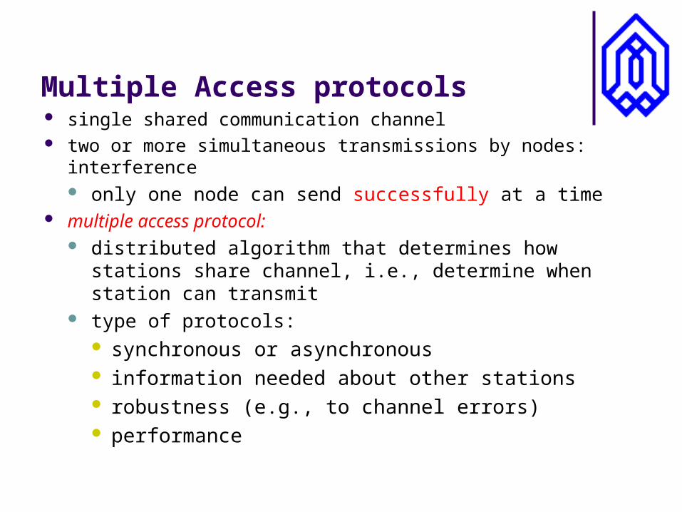
Multiple Access protocols single shared communication channel two or more simultaneous transmissions by nodes: interference
only one node can send successfully at a time multiple access protocol:
distributed algorithm that determines how stations share channel, i.e., determine when station can transmit
type of protocols: synchronous or asynchronous information needed about other stations robustness (e.g., to channel errors) performance
Multiple Access Control Protocols
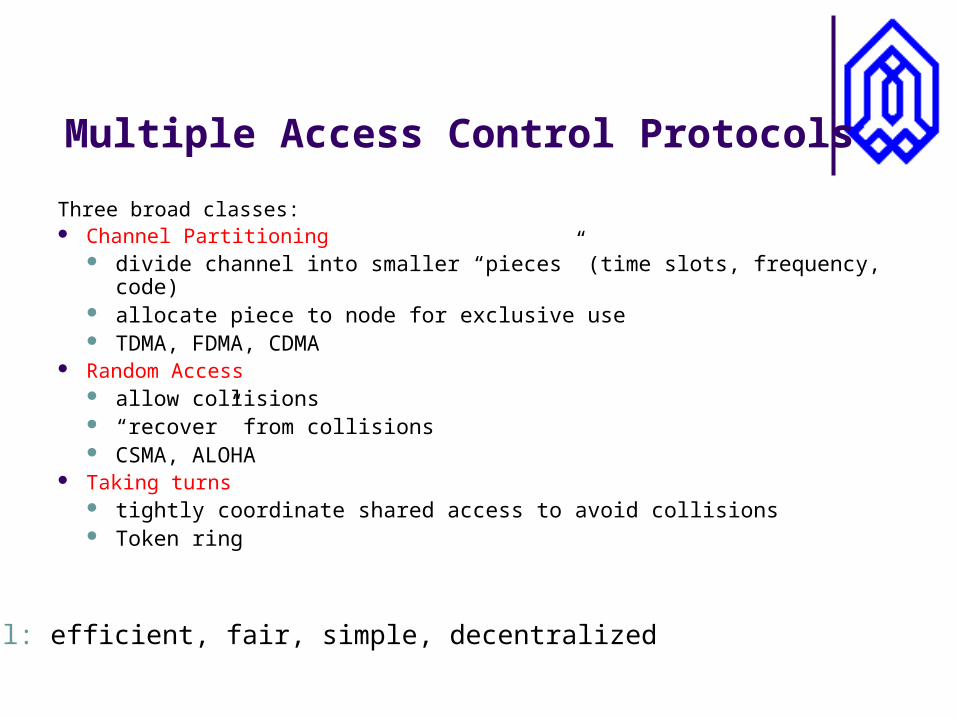
Three broad classes: Channel Partitioning
divide channel into smaller “pieces” (time slots, frequency, code) allocate piece to node for exclusive use TDMA, FDMA, CDMA
Random Access allow collisions “recover” from collisions CSMA, ALOHA
Taking turns tightly coordinate shared access to avoid collisions Token ring
Goal: efficient, fair, simple, decentralized
Random Access protocols
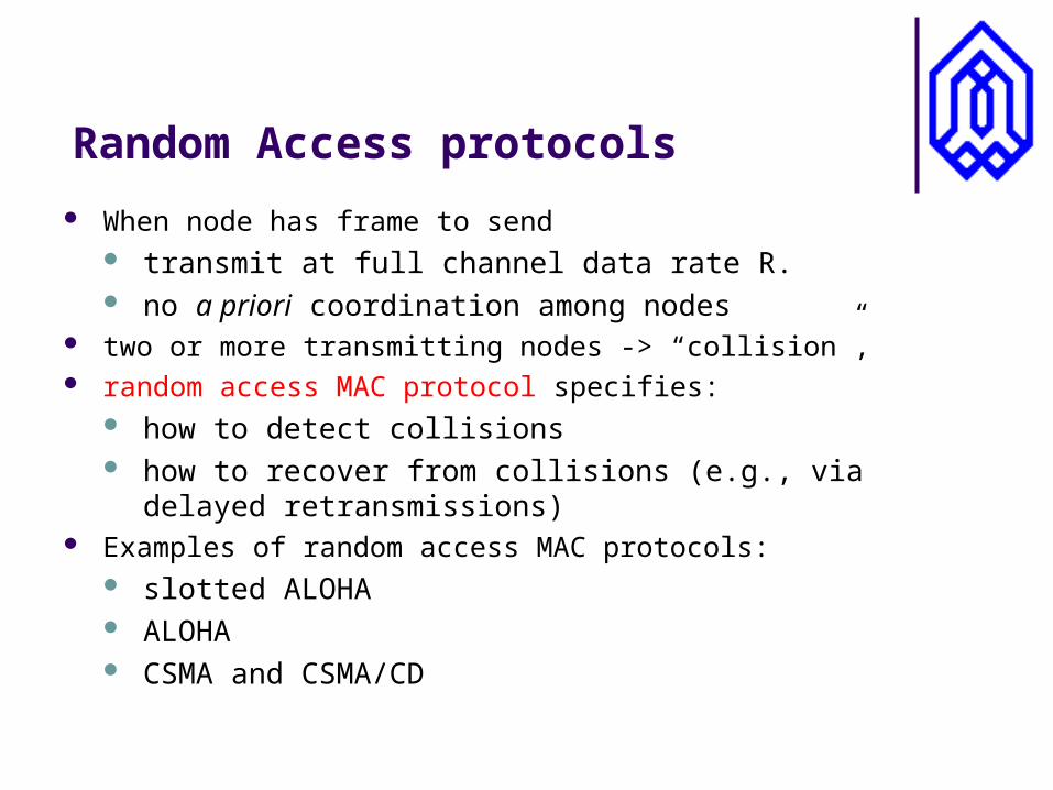
When node has frame to send transmit at full channel data rate R. no a priori coordination among nodes
two or more transmitting nodes -> “collision”, random access MAC protocol specifies:
how to detect collisions how to recover from collisions (e.g., via delayed retransmissions)
Examples of random access MAC protocols: slotted ALOHA ALOHA CSMA and CSMA/CD
CSMA: Carrier Sense Multiple Access
CSMA: listen before transmit: If channel sensed idle: transmit entire frame If channel sensed busy, defer transmission
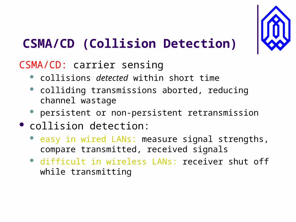
CSMA/CD (Collision Detection)
CSMA/CD: carrier sensing collisions detected within short time colliding transmissions aborted, reducing channel wastage persistent or non-persistent retransmission
collision detection: easy in wired LANs: measure signal strengths, compare
transmitted, received signals difficult in wireless LANs: receiver shut off while
transmitting
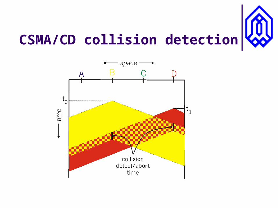
CSMA/CD collision detection
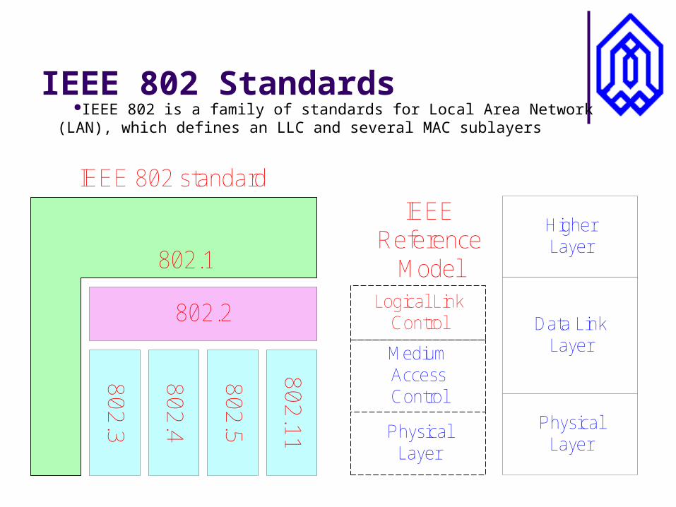
IEEE 802 StandardsIEEE 802 is a family of standards for Local Area Network
(LAN), which defines an LLC and several MAC sublayers
80
2.3
80
2.4
80
2.5
80
2.1
1
802.2
802.1
IEEE 802 standard
MediumAccessControl
PhysicalLayer
Logical LinkControl
IEEEReference
Model
PhysicalLayer
Data LinkLayer
HigherLayer
MAC Address
MAC address allocation administered by IEEE manufacturer buys portion of MAC address space (to assure
uniqueness) Analogy: (a) MAC address: like Social Security Number (b) IP address: like postal address MAC flat address => portability
can move LAN card from one LAN to another IP hierarchical address NOT portable
depends on network to which one attaches
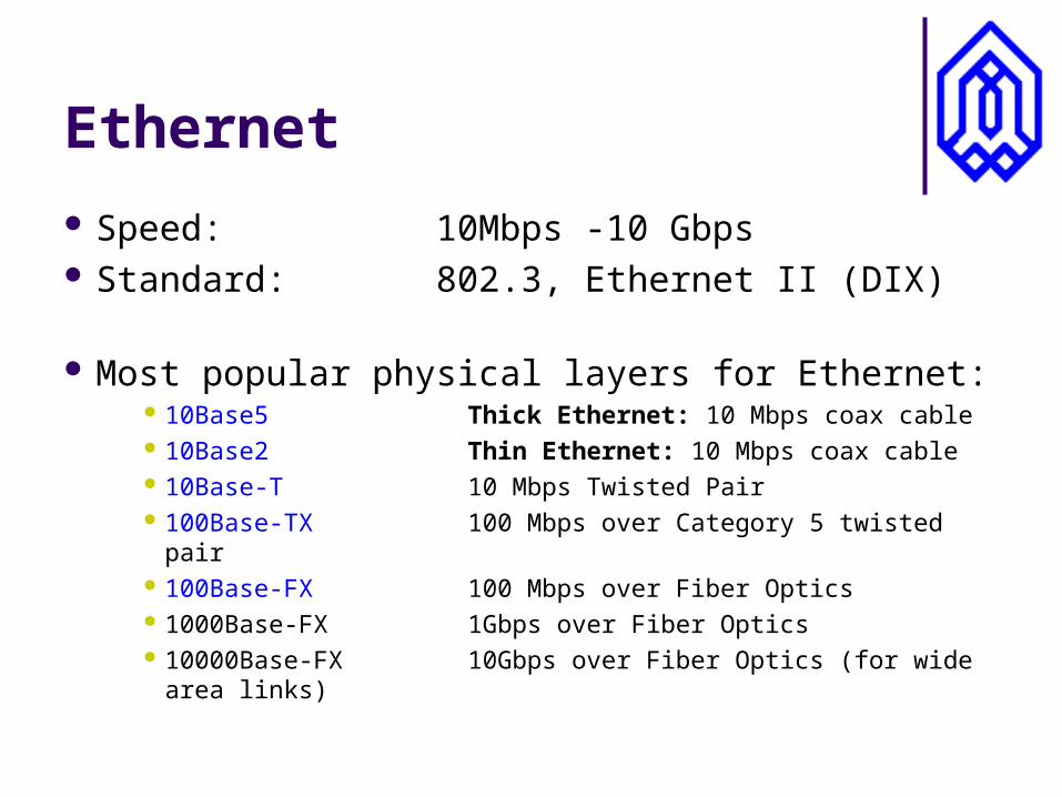
Ethernet
Speed: 10Mbps -10 Gbps Standard: 802.3, Ethernet II (DIX)
Most popular physical layers for Ethernet:
10Base5 Thick Ethernet: 10 Mbps coax cable 10Base2 Thin Ethernet: 10 Mbps coax cable 10Base-T 10 Mbps Twisted Pair 100Base-TX 100 Mbps over Category 5 twisted pair 100Base-FX 100 Mbps over Fiber Optics 1000Base-FX 1Gbps over Fiber Optics 10000Base-FX 10Gbps over Fiber Optics (for wide area
links)
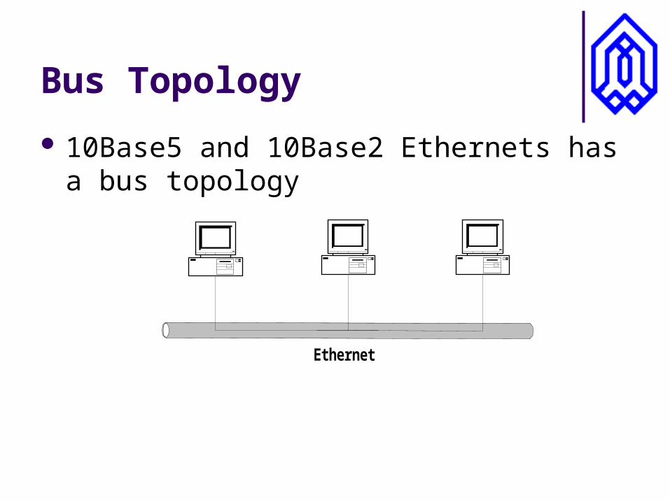
Bus Topology
Ethernet
10Base5 and 10Base2 Ethernets has a bus topology
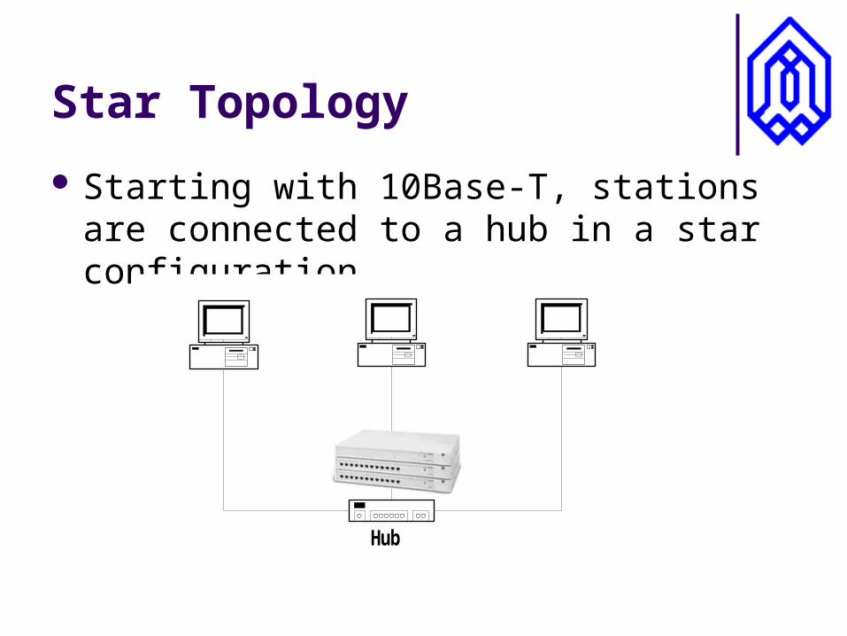
Starting with 10Base-T, stations are connected to a hub in a star configuration
Star Topology
Hub
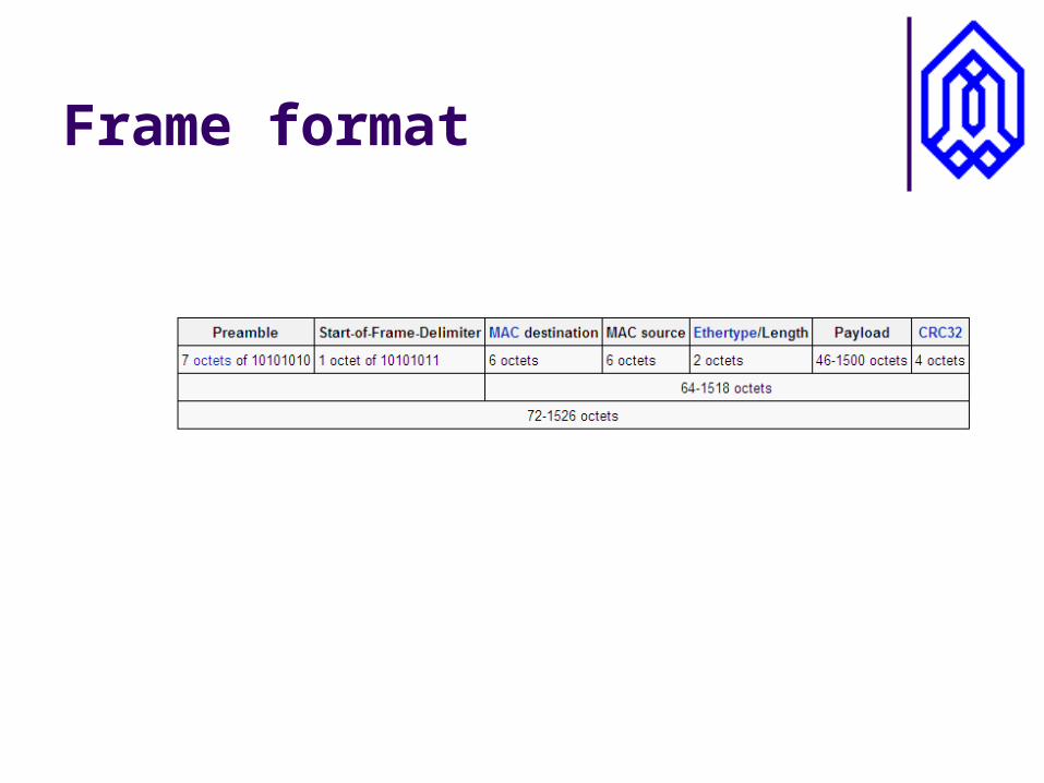
Frame format
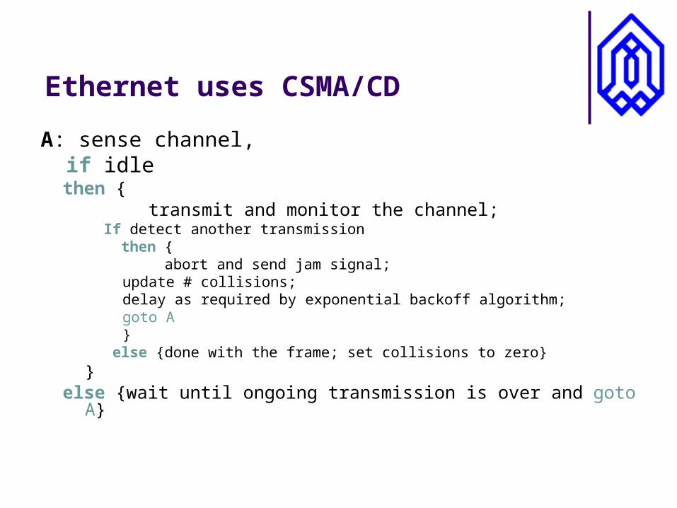
Ethernet uses CSMA/CD
A: sense channel, if idle
then { transmit and monitor the channel;
If detect another transmission then { abort and send jam signal;
update # collisions; delay as required by exponential backoff algorithm; goto A}
else {done with the frame; set collisions to zero}}
else {wait until ongoing transmission is over and goto A}
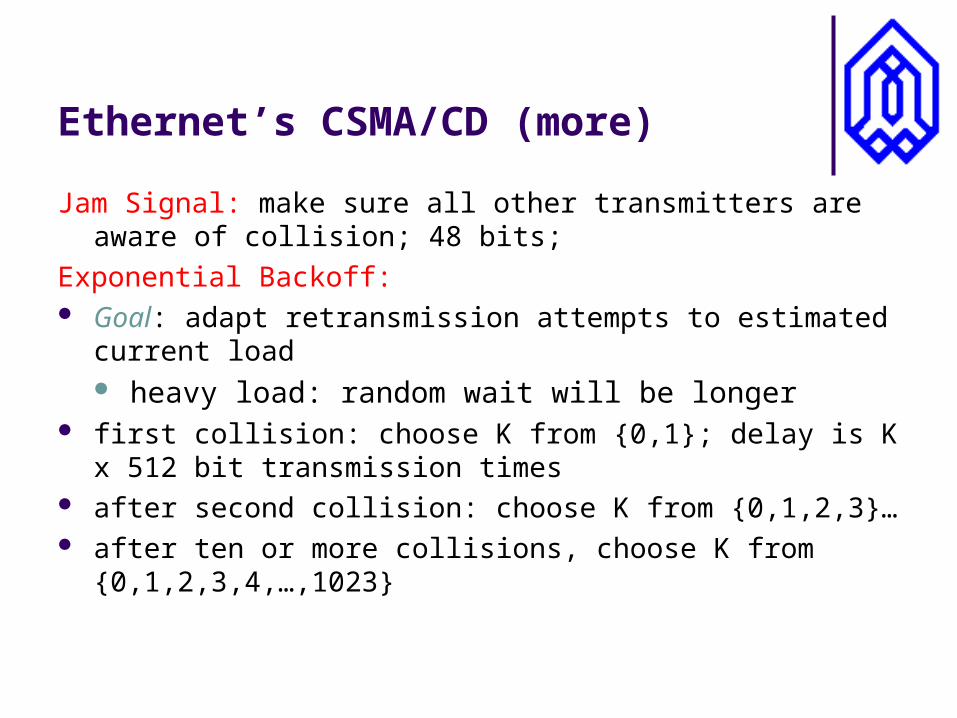
Ethernet’s CSMA/CD (more)
Jam Signal: make sure all other transmitters are aware of collision; 48 bits;
Exponential Backoff: Goal: adapt retransmission attempts to estimated current load
heavy load: random wait will be longer first collision: choose K from {0,1}; delay is K x 512 bit
transmission times after second collision: choose K from {0,1,2,3}… after ten or more collisions, choose K from {0,1,2,3,4,…,1023}
Interconnecting LANs
Q: Why not just one big LAN? Limited amount of supportable traffic: on single LAN, all stations
must share bandwidth limited length: 802.3 specifies maximum cable length large “collision domain” (can collide with many stations)
Hubs, Bridges and Switches
Hubs
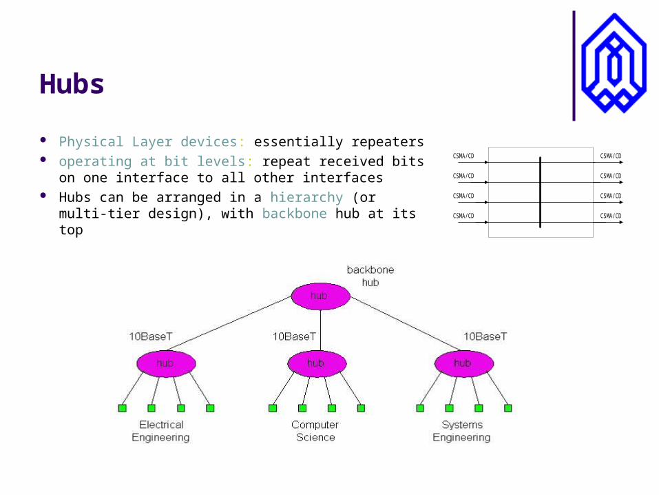
Physical Layer devices: essentially repeaters operating at bit levels: repeat received bits on
one interface to all other interfaces Hubs can be arranged in a hierarchy (or multi-
tier design), with backbone hub at its top
CSMA/CD
CSMA/CD
CSMA/CD
CSMA/CD
CSMA/CD
CSMA/CD
CSMA/CD
CSMA/CD
Hubs (more)
Each connected LAN referred to as LAN segment Hubs do not isolate collision domains: node may collide with any
node residing at any segment in LAN Hub Advantages:
simple, inexpensive device Multi-tier provides graceful degradation:
portions of the LAN continue to operate if one hub malfunctions
extends maximum distance between node pairs (100m per Hub)
Hub limitations
single collision domain results in no increase in max throughput multi-tier throughput same as single segment throughput limit the number of nodes and geographical coverage
cannot connect different Ethernet types (e.g., 10BaseT and 100baseT)
Bridges
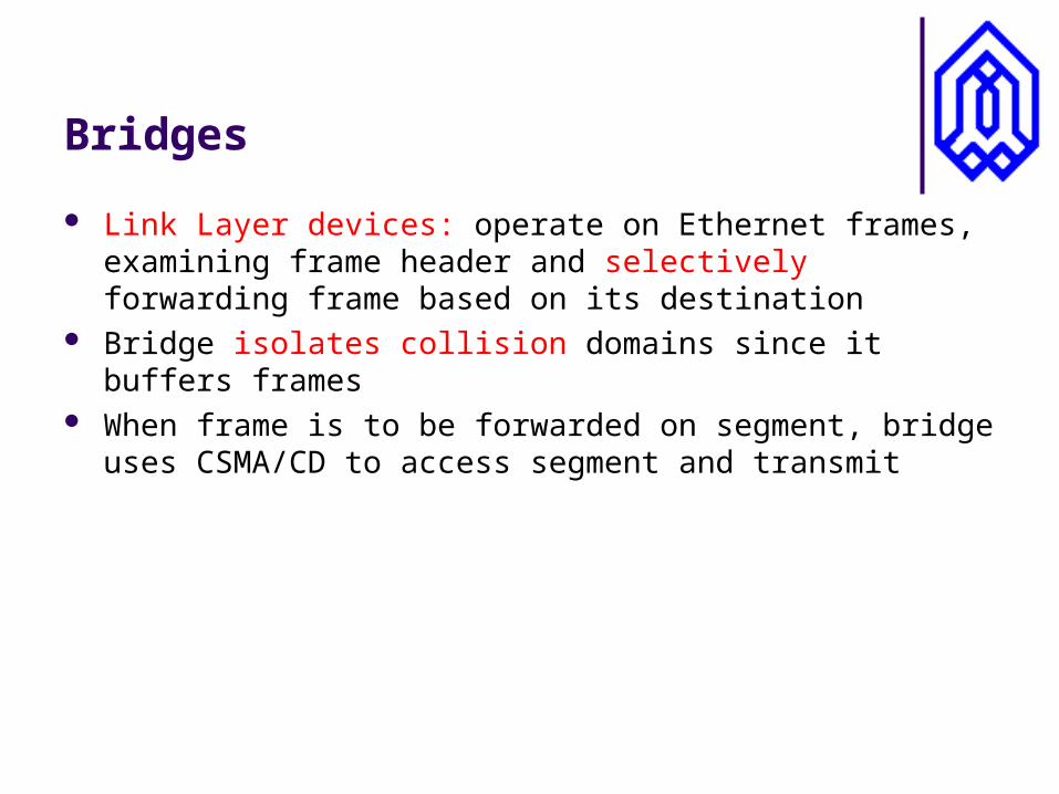
Link Layer devices: operate on Ethernet frames, examining frame header and selectively forwarding frame based on its destination
Bridge isolates collision domains since it buffers frames When frame is to be forwarded on segment, bridge uses
CSMA/CD to access segment and transmit
Bridges (more)
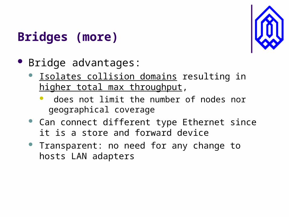
Bridge advantages: Isolates collision domains resulting in higher total max
throughput, does not limit the number of nodes nor geographical
coverage Can connect different type Ethernet since it is a store and
forward device Transparent: no need for any change to hosts LAN
adapters
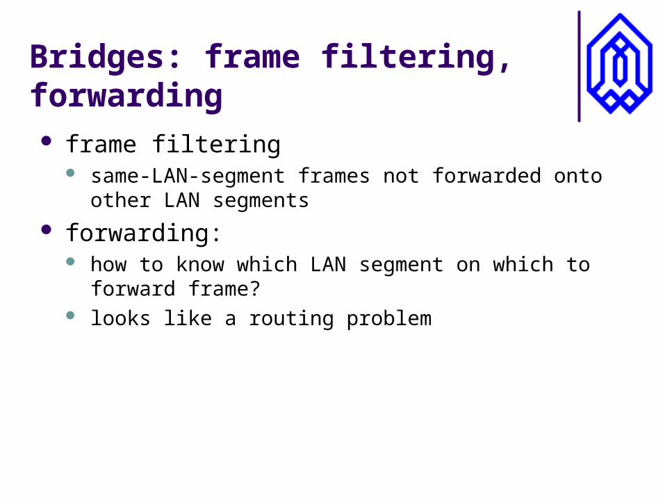
Bridges: frame filtering, forwarding frame filtering
same-LAN-segment frames not forwarded onto other LAN segments
forwarding: how to know which LAN segment on which to forward
frame? looks like a routing problem
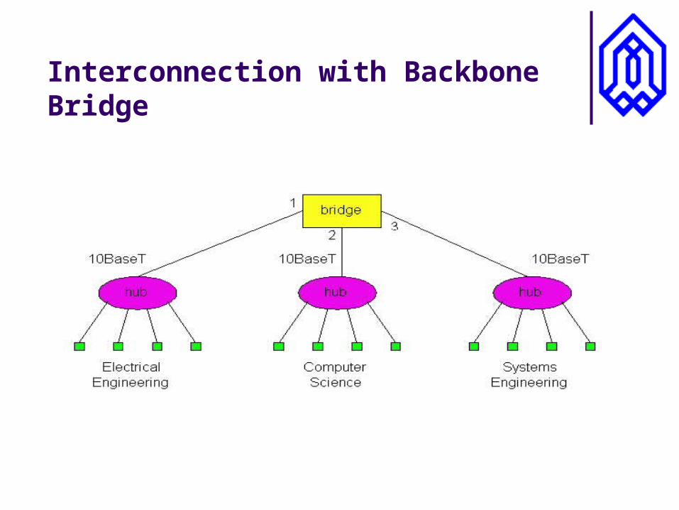
Interconnection with Backbone Bridge
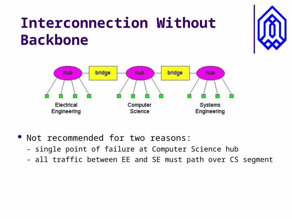
Interconnection Without Backbone
Not recommended for two reasons:- single point of failure at Computer Science hub
- all traffic between EE and SE must path over CS segment
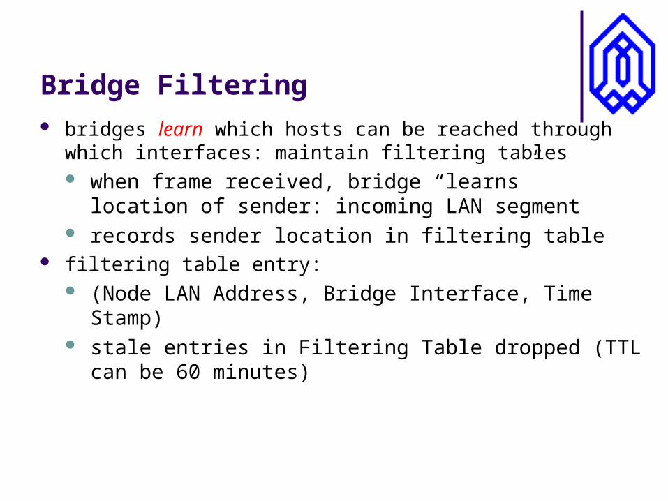
Bridge Filtering bridges learn which hosts can be reached through which
interfaces: maintain filtering tables when frame received, bridge “learns” location of sender:
incoming LAN segment records sender location in filtering table
filtering table entry: (Node LAN Address, Bridge Interface, Time Stamp) stale entries in Filtering Table dropped (TTL can be 60
minutes)
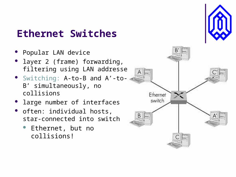
Ethernet Switches
Popular LAN device layer 2 (frame) forwarding, filtering
using LAN addresses Switching: A-to-B and A’-to-B’
simultaneously, no collisions large number of interfaces often: individual hosts, star-
connected into switch Ethernet, but no collisions!
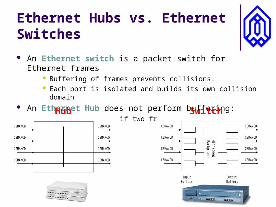
Ethernet Hubs vs. Ethernet Switches
An Ethernet switch is a packet switch for Ethernet frames Buffering of frames prevents collisions. Each port is isolated and builds its own collision domain
An Ethernet Hub does not perform buffering: Collisions occur if two frames arrive at the same time.
HighS
peedB
ackplane
CSMA/CD
CSMA/CD
CSMA/CD
CSMA/CD
CSMA/CD
CSMA/CD
CSMA/CD
CSMA/CD
OutputBuffers
InputBuffers
CSMA/CD
CSMA/CD
CSMA/CD
CSMA/CD
CSMA/CD
CSMA/CD
CSMA/CD
CSMA/CD
Hub Switch
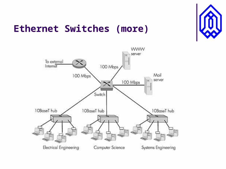
Ethernet Switches (more)
Shared