Embed Size (px)
Citation preview
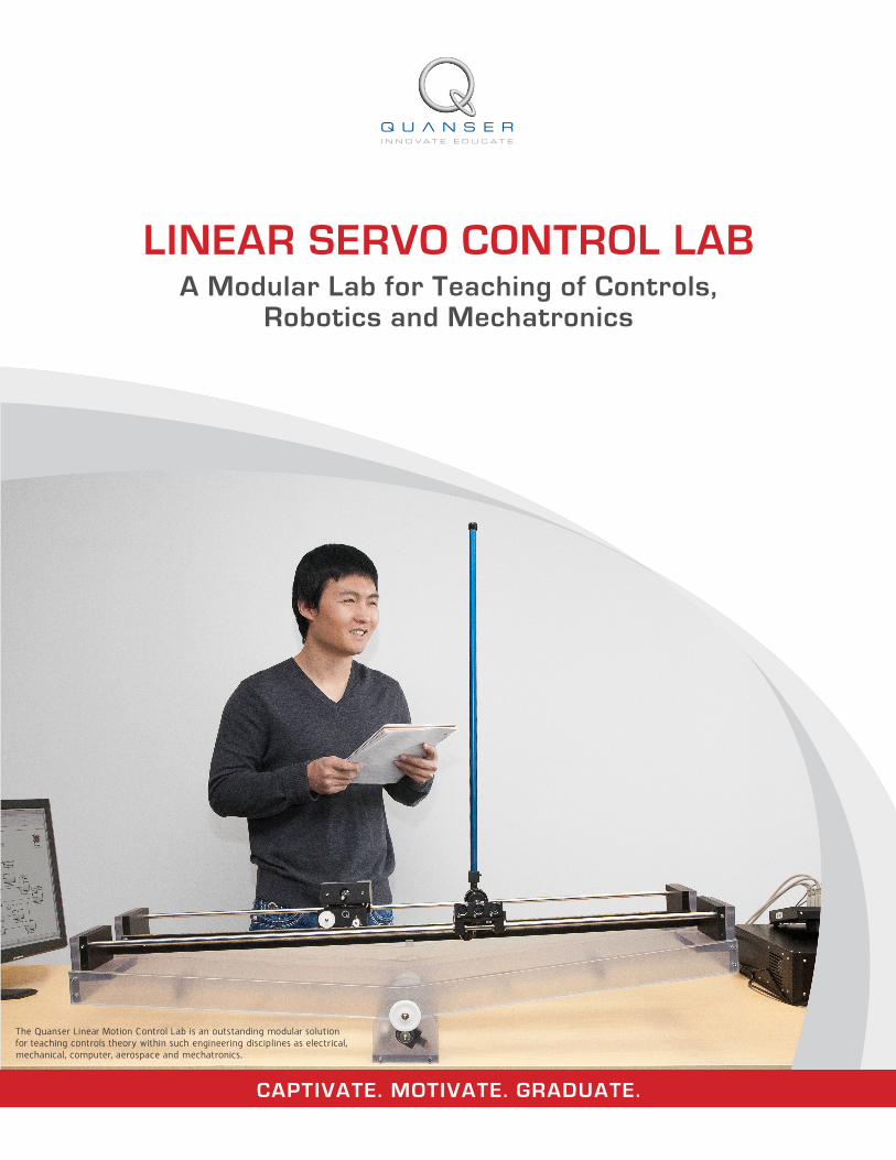
LINEAR SERVO CONTROL LAB A Modular Lab for Teaching of Controls,
Robotics and Mechatronics
The Quanser Linear Motion Control Lab is an outstanding modular solution for teaching controls theory within such engineering disciplines as electrical, mechanical, computer, aerospace and mechatronics.
CAPTIVATE. MOTIVATE. GRADUATE.
With Quanser offering a complete Linear Motion Control Lab, sourcing reliable equipment need not distract you from your larger goals of attracting the best students, achieving desired learning outcomes and finding time to conduct your research. We can work with you to create a long term plan to build the lab you need while respecting your budget and timelines.
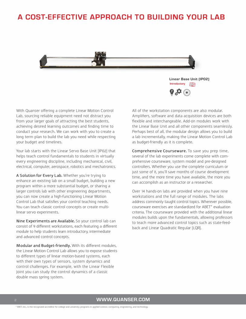
Your lab starts with the Linear Servo Base Unit (IP02) that helps teach control fundamentals to students in virtually every engineering discipline, including mechanical, civil, electrical, computer, aerospace, robotics and mechatronics.
A Solution for Every Lab. Whether you’re trying to enhance an existing lab on a small budget, building a new program within a more substantial budget, or sharing a larger controls lab with other engineering departments, you can now create a high-functioning Linear Motion Control Lab that satisfies your control teaching needs. You can teach classic control concepts or create multi-linear servo experiments.
Nine Experiments are Available. So your control lab can consist of 9 different workstations, each featuring a different module to help students learn introductory, intermediate and advanced control concepts.
Modular and Budget-friendly. With its different modules, the Linear Motion Control Lab allows you to expose students to different types of linear motion-based systems, each with their own types of sensors, system dynamics and control challenges. For example, with the Linear Flexible Joint you can study the control dynamics of a classic double mass spring system.
All of the workstation components are also modular. Amplifiers, software and data acquisition devices are both flexible and interchangeable. Add-on modules work with the Linear Base Unit and all other components seamlessly. Perhaps best of all, the modular design allows you to build a lab incrementally, making the Linear Motion Control Lab as budget-friendly as it is complete.
Comprehensive Courseware. To save you prep time, several of the lab experiments come complete with com-prehensive courseware, system model and pre-designed controllers. Whether you use the complete curriculum or just some of it, you’ll save months of course development time, and the more time you have available, the more you can accomplish as an instructor or a researcher.
Over 14 hands-on labs are provided when you have nine workstations and the full range of modules. The labs address commonly taught control topics. Wherever possible, courseware exercises are standardized for ABET* evaluation criteria. The courseware provided with the additional linear modules builds upon the fundamentals, allowing professors to teach more advanced control topics such as state-feed-back and Linear Quadratic Regular (LQR).
A COST-EFFECTIVE APPROACH TO BUILDING YOUR LAB
2 WWW.QUANSER.COM* ABET, Inc., is the recognized accreditor for college and university programs in applied science, computing, engineering, and technology.
Linear Base Unit (IP02) Introductory
3TO REQUEST A QUOTE, PLEASE EMAIL [email protected] 3TO REQUEST A QUOTE, PLEASE EMAIL [email protected]* This experiment setup requires two Seesaw and two Linear Pendulum modules
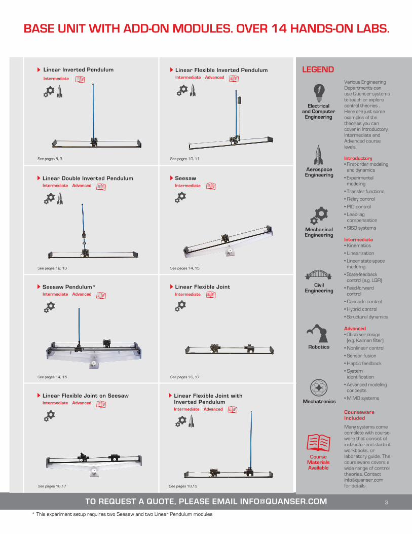
BASE UNIT WITH ADD-ON MODULES. OVER 14 HANDS-ON LABS.
LEGEND
Robotics
Mechanical Engineering
Civil Engineering
Electrical and Computer
Engineering
Mechatronics
Aerospace Engineering
Course Materials Available
Various Engineering Departments can use Quanser systems to teach or explore control theories . Here are just some examples of the theories you can cover in Introductory, Intermediate and Advanced course levels.
Introductory• First-order modeling and dynamics
• Experimental modeling
• Transfer functions
• Relay control
• PID control
• Lead-lag compensation
• SISO systems
Intermediate• Kinematics
• Linearization
• Linear state-space modeling
• State-feedback control (e.g. LQR)
• Feed-forward control
• Cascade control
• Hybrid control
• Structural dynamics
Advanced• Observer design (e.g. Kalman filter)
• Nonlinear control
• Sensor fusion
• Haptic feedback
• System identification
• Advanced modeling concepts
• MIMO systems
Courseware Included
Many systems come complete with course-ware that consist of instructor and student workbooks, or laboratory guide. The courseware covers a wide range of control theories. Contact [email protected] for details.
See pages 8, 9
Linear Inverted Pendulum
Intermediate
Linear Flexible Inverted PendulumIntermediate Advanced
Linear Double Inverted PendulumIntermediate Advanced
See pages 10, 11
See pages 12, 13
Linear Flexible JointIntermediate
See pages 16, 17
Linear Flexible Joint with Inverted PendulumIntermediate Advanced
See pages 18,19
SeesawIntermediate
See pages 14, 15
Seesaw Pendulum*Intermediate Advanced
See pages 14, 15
Linear Flexible Joint on SeesawIntermediate Advanced
See pages 16,17

Pictured above: Quanser Linear Inverted Pendulum, Quanser VoltPAQ-X1 amplifier, Q2-USB data acquisition device, Quanser Control Software.
4 WWW.QUANSER.COM
“ Students like to work with Quanser equipment.
It is easy for them to get started. They just follow the wiring procedure and
everything else is just mouse-clicking. Using Quanser rapid control prototyping
and real-time software, they can control physical systems in no time.”
Dr. YangQuan Chen, Assistant Professor, Department of Electrical and Computer Engineering,
Utah State University, USA
The Linear Motion Control Lab is one of the most popular, flexible and modular solutions for teaching controls. Based on the world’s leading turn-key platform for controls education, it is designed to help engineering educators reach a new level of efficiency and effectiveness in teaching controls.
The Linear Motion Control Lab comes complete with all the components and peripherals you need. You receive a versatile, robust, optimized and integrated workstation that offers peace of mind, flexibility and maximum efficiency.
Control Design SoftwareQuanser’s control design software makes developing and running real-time control models straightforward, eliminating any need for hand-coding. It seamlessly integrates with either MATLAB®/Simulink® or NI LabVIEW™.1
Quanser Courseware and Pre-Designed Controllers Pedagogical curriculum2 is provided with most Linear Motion workstations and covers a wide range of popular control topics. Instructor and Student Workbooks come complete with pre-lab assignments and in-lab, step by step instructions. These materi-als are designed to save time on course development. Work-books and comprehensive student assignments are ready to use right out of the box. Quanser Linear Motion work-stations also come with pre-designed controllers based on either Quanser QUARC® with MATLAB®/Simulink® or Quanser RCP Toolkit for NI LabVIEW™.
Quanser Experiment and AmplifierTo help your engineering students assimilate controls theory and stay motivated, create a lab that offers many workstations featuring the Linear Servo Base Unit and different add-on modules. This allows you to cover a wider range of control topics, from introductory to advanced, and expose students to dif-ferent hardware. Several linear voltage amplifiers are available
CAPTIVATE. MOTIVATE. GRADUATE.
to support the experiments. Small, lightweight and portable, they are ideal for all complex controls configurations related to educational or research needs.
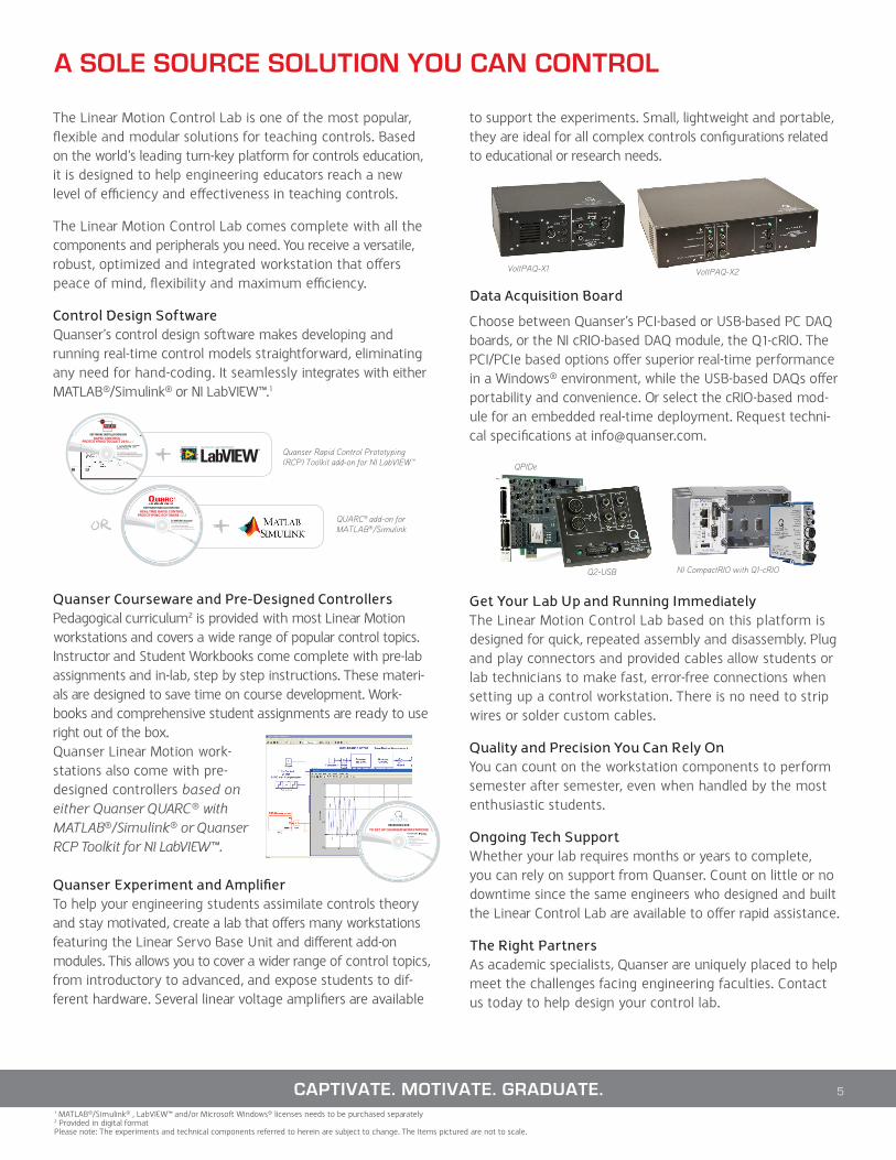
Data Acquisition Board
Choose between Quanser’s PCI-based or USB-based PC DAQ boards, or the NI cRIO-based DAQ module, the Q1-cRIO. The PCI/PCIe based options offer superior real-time performance in a Windows® environment, while the USB-based DAQs offer portability and convenience. Or select the cRIO-based mod-ule for an embedded real-time deployment. Request techni-cal specifications at [email protected].
Get Your Lab Up and Running ImmediatelyThe Linear Motion Control Lab based on this platform is designed for quick, repeated assembly and disassembly. Plug and play connectors and provided cables allow students or lab technicians to make fast, error-free connections when setting up a control workstation. There is no need to strip wires or solder custom cables.
Quality and Precision You Can Rely OnYou can count on the workstation components to perform semester after semester, even when handled by the most enthusiastic students.
Ongoing Tech SupportWhether your lab requires months or years to complete, you can rely on support from Quanser. Count on little or no downtime since the same engineers who designed and built the Linear Control Lab are available to offer rapid assistance.
The Right PartnersAs academic specialists, Quanser are uniquely placed to help meet the challenges facing engineering faculties. Contact us today to help design your control lab.
5
1 MATLAB®/Simulink® , LabVIEW™ and/or Microsoft Windows® licenses needs to be purchased separately2 Provided in digital formatPlease note: The experiments and technical components referred to herein are subject to change. The Items pictured are not to scale.
A SOLE SOURCE SOLUTION YOU CAN CONTROL
QUARC® add-on for MATLAB®/Simulink
Quanser Rapid Control Prototyping (RCP) Toolkit add-on for NI LabVIEW™
VoltPAQ-X1 VoltPAQ-X2
Q2-USB NI CompactRIO with Q1-cRIO
QPIDe
6
LINEAR SERVO BASE UNIT (IP02)
WWW.QUANSER.COM
The Linear Servo Base Unit experiment relates to several real-world applications. For example, students can easily identify with speed control exercises as they relate to vehicle cruise control.
LINEAR SERVO BASE UNIT (IP02)
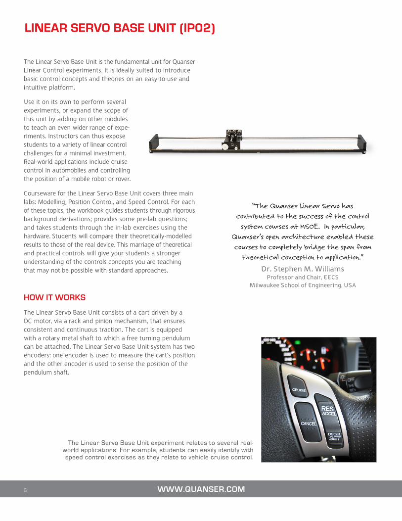
The Linear Servo Base Unit is the fundamental unit for Quanser Linear Control experiments. It is ideally suited to introduce basic control concepts and theories on an easy-to-use and intuitive platform.
Use it on its own to perform several experiments, or expand the scope of this unit by adding on other modules to teach an even wider range of expe-riments. Instructors can thus expose students to a variety of linear control challenges for a minimal investment. Real-world applications include cruise control in automobiles and controlling the position of a mobile robot or rover.
Courseware for the Linear Servo Base Unit covers three main labs: Modelling, Position Control, and Speed Control. For each of these topics, the workbook guides students through rigorous background derivations; provides some pre-lab questions; and takes students through the in-lab exercises using the hardware. Students will compare their theoretically-modelled results to those of the real device. This marriage of theoretical and practical controls will give your students a stronger understanding of the controls concepts you are teaching that may not be possible with standard approaches.
HOW IT WORKS
The Linear Servo Base Unit consists of a cart driven by a DC motor, via a rack and pinion mechanism, that ensures consistent and continuous traction. The cart is equipped with a rotary metal shaft to which a free turning pendulum can be attached. The Linear Servo Base Unit system has two encoders: one encoder is used to measure the cart’s position and the other encoder is used to sense the position of the pendulum shaft.
“The Quanser Linear Servo has
contributed to the success of the control
system courses at MSOE. In particular,
Quanser’s open architecture enabled these
courses to completely bridge the span from
theoretical conception to application.”
Dr. Stephen M. Williams Professor and Chair, EECS
Milwaukee School of Engineering, USA

Component Description
Plant • Linear Servo Base Unit (IP02)
Controller Design Environment1 • Quanser QUARC® add-on for MATLAB®/Simulink®• Quanser Rapid Control Prototyping (RCP) Toolkit® add-on for NI LabVIEW™
Documentation2 • ABET-aligned* Instructor Workbook • ABET-aligned* Student Workbook• User Manual • Quick Start Guide
Targets1 • Microsoft Windows® or NI CompactRIO
Data Acquisition Board • Quanser Q2-USB, Q8-USB, QPID/QPIDe, NI PCI/PCIe DAQ device or Quanser Q1-cRIO
Amplifier • Quanser VoltPAQ-X1
Others • Complete dynamic model • Simulink® pre-designed controllers• LabVIEW™ pre-designed controllers
CURRICULUM TOPICS PROVIDED
Modeling Topics• Derivation of dynamic model from first-principles• Transfer function representation• Model validation
Control Topics• PID• Lead Compensator design
FEATURES
• Easily interchangeable add-on modules• High quality MICROMO™ DC motor and gearbox• High resolution optical encoders to sense position• Robust machined aluminum casing • Easy-connect cables and connectors• Fully compatible with MATLAB®/Simulink® and LabVIEW™
• Fully documented system models and parameters provided for MATLAB®/Simulink®, LabVIEW™ and Maple™
• Open architecture design, allowing users to design their own controller
System Specifications Linear Servo Base Unit
DEVICE SPECIFICATIONS
SPECIFICATION VALUE UNITSRack dimensions (L x W x H) 102 x 15 x 6.1 cmCart mass 0.57 kgCart weight mass 0.37 kgMotor nominal voltage 6 VMotor maximum continuous current (recommended) 1 AMotor maximum speed (recommended) 6000 RPMPlanetary gear box ratio 3.71Encoder resolution (in quadrature) 4096 counts/rev
Workstation Components Linear Base Unit Experiment
1 MATLAB®/Simulink®, LabVIEW™ and Microsoft Windows® licenses need to be purchased separately2 Documentation provided in digital format
* ABET, Inc., is the recognized accreditor for college and university programs in applied science, computing, engineering, and technology
TO REQUEST A QUOTE, PLEASE EMAIL [email protected] 7
8 WWW.QUANSER.COM
LINEAR INVERTED PENDULUM WORKSTATION
The Linear Servo Base Unit is supplied with pendulums that can be used to perform a variety of experiments, including the classic inverted pendulum experiment, where students must design a controller that balances a vertical rod by moving the cart. Three experiments are supplied with the pendulum setup: Gantry Crane, Inverted Pendulum, and the Self-Erecting Inverted Pendulum.
The Gantry Crane emulates a crane on a movable platform that is typically used to transport items in a warehouse or shipping yard. In this case, the cart represents the gantry platform and the pendulum acts as the crane. Students can learn how to mitigate the motions of the downward pendulum while the cart travels to different positions.
With the Self-Erecting Inverted Pendulum experiment, students have the opportunity to design a controller that swings the pen-dulum up and maintains it in the upright position.
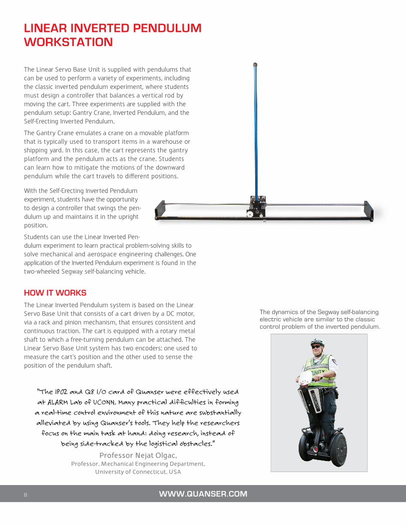
Students can use the Linear Inverted Pen-dulum experiment to learn practical problem-solving skills to solve mechanical and aerospace engineering challenges. One application of the Inverted Pendulum experiment is found in the two-wheeled Segway self-balancing vehicle.
HOW IT WORKSThe Linear Inverted Pendulum system is based on the Linear Servo Base Unit that consists of a cart driven by a DC motor, via a rack and pinion mechanism, that ensures consistent and continuous traction. The cart is equipped with a rotary metal shaft to which a free-turning pendulum can be attached. The Linear Servo Base Unit system has two encoders: one used to measure the cart’s position and the other used to sense the position of the pendulum shaft.
The dynamics of the Segway self-balancing electric vehicle are similar to the classic control problem of the inverted pendulum.
“The IP02 and Q8 I/O card of Quanser were effectively used
at ALARM Lab of UCONN. Many practical difficulties in forming
a real-time control environment of this nature are substantially
alleviated by using Quanser’s tools. They help the researchers
focus on the main task at hand: doing research, instead of
being side-tracked by the logistical obstacles.”
Professor Nejat Olgac, Professor, Mechanical Engineering Department,
University of Connecticut, USA

CURRICULUM TOPICS PROVIDED
Modeling Topics• Derivation of dynamic model using Lagrange • State-space representation• Linearization
Control Topics• Linear-quadratic regulator (LQR)• Hybrid control• Pole placement• Energy-based/non-linear control
System Specifications Linear Inverted Pendulum Module
FEATURES
• High quality aluminum chassis with precision-crafted parts• High resolution optical encoders to sense pendulum angles• Two sizes supplied: medium and long• Pendulum easily attaches to front shaft of the Linear Servo Base Unit• Easy-connect cables and connectors (on the Linear Servo Base Unit)• Fully compatible with MATLAB®/Simulink® and LabVIEW™• Fully documented system models and parameters provided for
MATLAB®/Simulink®, LabVIEW™ and Maple™• Open architecture design, allowing users to design their own controller
DEVICE SPECIFICATIONS
SPECIFICATION VALUE UNITSMedium pendulum mass (with T-fitting) 0.127 kgMedium pendulum length (pivot to tip) 33.7 cmLong pendulum mass 0.230 kgLong pendulum length (pivot to tip) 64.1 cmEncoder resolution of linear servo base unit pendulum shaft (in quadrature) 4096 count/rev
Workstation Components Linear Inverted Pendulum ExperimentComponent Description
Plant • Linear Servo Base Unit (IP02)• Medium (12-inch) or Long (24-inch) Pendulum
Controller Design Environment1 • Quanser QUARC® add-on for MATLAB®/Simulink®• Quanser Rapid Control Prototyping (RCP) Toolkit® add-on for NI LabVIEW™
Documentation2 • ABET-aligned* Instructor Workbook • ABET-aligned* Student Workbook• User Manual• Quick Start Guide
Targets1 • Microsoft Windows® or NI CompactRIO
Data Acquisition Board • Quanser Q2-USB, Q8-USB, QPID/QPIDe, NI PCI/PCIe DAQ device or Quanser Q1-cRIO
Amplifier • Quanser VoltPAQ-X1
Others • Complete dynamic model • Simulink® pre-designed controllers• LabVIEW™ pre-designed controllers
CAPTIVATE. MOTIVATE. GRADUATE. 9
1 MATLAB®/Simulink®, LabVIEW™ and Microsoft Windows® licenses need to be purchased separately2 Documentation provided in digital format
* ABET, Inc., is the recognized accreditor for college and university programs in applied science, computing, engineering, and technology
LINEAR FLEXIBLE INVERTED PENDULUM WORKSTATION
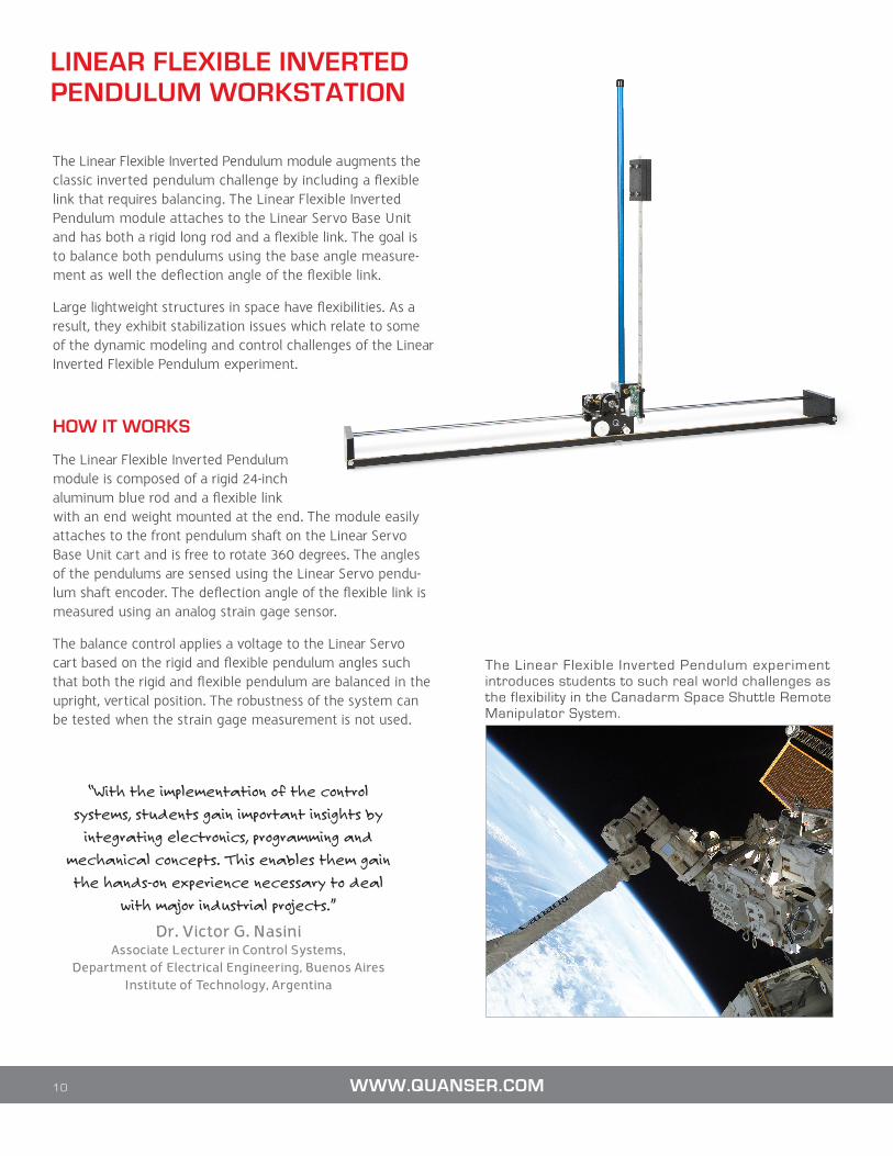
The Linear Flexible Inverted Pendulum module augments the classic inverted pendulum challenge by including a flexible link that requires balancing. The Linear Flexible Inverted Pendulum module attaches to the Linear Servo Base Unit and has both a rigid long rod and a flexible link. The goal is to balance both pendulums using the base angle measure-ment as well the deflection angle of the flexible link.
Large lightweight structures in space have flexibilities. As a result, they exhibit stabilization issues which relate to some of the dynamic modeling and control challenges of the Linear Inverted Flexible Pendulum experiment.
HOW IT WORKS
The Linear Flexible Inverted Pendulum module is composed of a rigid 24-inch aluminum blue rod and a flexible link with an end weight mounted at the end. The module easily attaches to the front pendulum shaft on the Linear Servo Base Unit cart and is free to rotate 360 degrees. The angles of the pendulums are sensed using the Linear Servo pendu-lum shaft encoder. The deflection angle of the flexible link is measured using an analog strain gage sensor.
The balance control applies a voltage to the Linear Servo cart based on the rigid and flexible pendulum angles such that both the rigid and flexible pendulum are balanced in the upright, vertical position. The robustness of the system can be tested when the strain gage measurement is not used.
The Linear Flexible Inverted Pendulum experiment introduces students to such real world challenges as the flexibility in the Canadarm Space Shuttle Remote Manipulator System.
10 WWW.QUANSER.COM
“With the implementation of the control
systems, students gain important insights by
integrating electronics, programming and
mechanical concepts. This enables them gain
the hands-on experience necessary to deal
with major industrial projects.”
Dr. Victor G. Nasini Associate Lecturer in Control Systems,
Department of Electrical Engineering, Buenos Aires Institute of Technology, Argentina
CURRICULUM TOPICS PROVIDED
Modeling Topics• Derivation of dynamic model using Lagrange• State-space representation• Linearization
Control Topics• Linear-quadratic regulator (LQR)
FEATURES
• High quality aluminum and precision-crafted parts• High resolution optical encoder to sense pendulum angle • Strain gage used to measure flexible pendulum deflection• 24-inch rigid blue pendulum and flexible link with end-weight• Easy-connect cables and connectors• Linear Flexible Inverted Pendulum module easily attaches to front shaft
of the Linear Servo Base Unit
• Flexible operation and control design from LabVIEW™ using the Quanser Rapid Control Prototyping (RCP) Toolkit
• Fully documented system models and parameters provided for LabVIEW™ and Maple™
• Open architecture design, allowing users to design their own controller
System Specifications Linear Flexible Inverted Pendulum Module
DEVICE SPECIFICATIONS
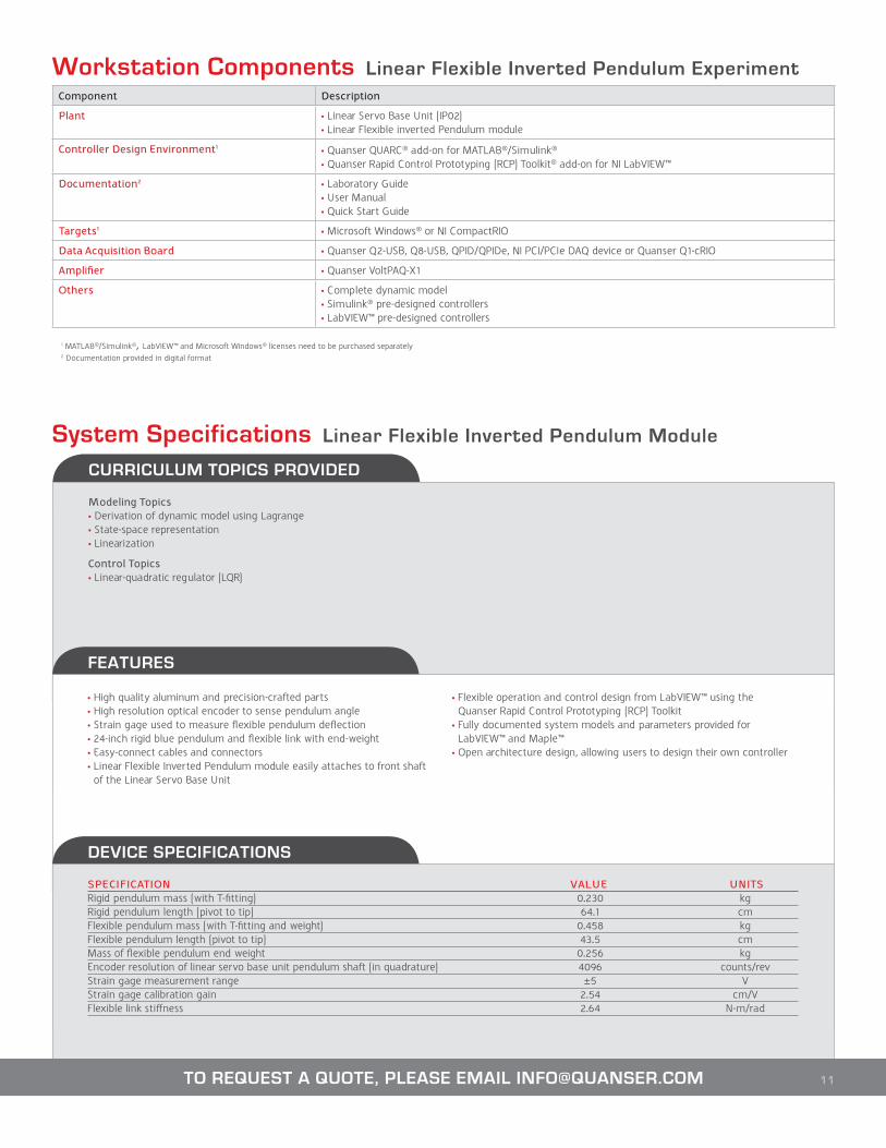
SPECIFICATION VALUE UNITSRigid pendulum mass (with T-fitting) 0.230 kgRigid pendulum length (pivot to tip) 64.1 cmFlexible pendulum mass (with T-fitting and weight) 0.458 kgFlexible pendulum length (pivot to tip) 43.5 cmMass of flexible pendulum end weight 0.256 kgEncoder resolution of linear servo base unit pendulum shaft (in quadrature) 4096 counts/revStrain gage measurement range ±5 VStrain gage calibration gain 2.54 cm/VFlexible link stiffness 2.64 N-m/rad
Workstation Components Linear Flexible Inverted Pendulum ExperimentComponent Description
Plant • Linear Servo Base Unit (IP02)• Linear Flexible inverted Pendulum module
Controller Design Environment1 • Quanser QUARC® add-on for MATLAB®/Simulink®• Quanser Rapid Control Prototyping (RCP) Toolkit® add-on for NI LabVIEW™
Documentation2 • Laboratory Guide• User Manual• Quick Start Guide
Targets1 • Microsoft Windows® or NI CompactRIO
Data Acquisition Board • Quanser Q2-USB, Q8-USB, QPID/QPIDe, NI PCI/PCIe DAQ device or Quanser Q1-cRIO
Amplifier • Quanser VoltPAQ-X1
Others • Complete dynamic model • Simulink® pre-designed controllers• LabVIEW™ pre-designed controllers
11TO REQUEST A QUOTE, PLEASE EMAIL [email protected]
1 MATLAB®/Simulink®, LabVIEW™ and Microsoft Windows® licenses need to be purchased separately2 Documentation provided in digital format
12
LINEAR DOUBLE INVERTED PENDULUM WORKSTATION
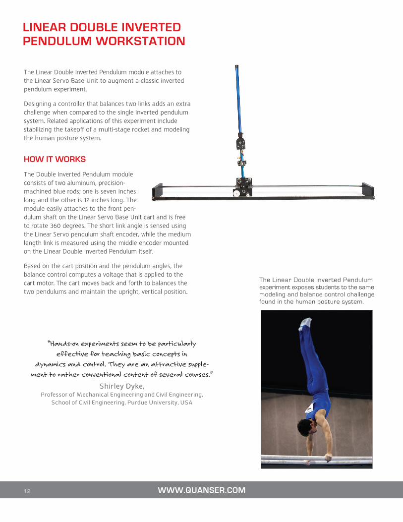
The Linear Double Inverted Pendulum module attaches to the Linear Servo Base Unit to augment a classic inverted pendulum experiment.
Designing a controller that balances two links adds an extra challenge when compared to the single inverted pendulum system. Related applications of this experiment include stabilizing the takeoff of a multi-stage rocket and modeling the human posture system.
HOW IT WORKS
The Double Inverted Pendulum module consists of two aluminum, precision-machined blue rods; one is seven inches long and the other is 12 inches long. The module easily attaches to the front pen-dulum shaft on the Linear Servo Base Unit cart and is free to rotate 360 degrees. The short link angle is sensed using the Linear Servo pendulum shaft encoder, while the medium length link is measured using the middle encoder mounted on the Linear Double Inverted Pendulum itself.
Based on the cart position and the pendulum angles, the balance control computes a voltage that is applied to the cart motor. The cart moves back and forth to balances the two pendulums and maintain the upright, vertical position.
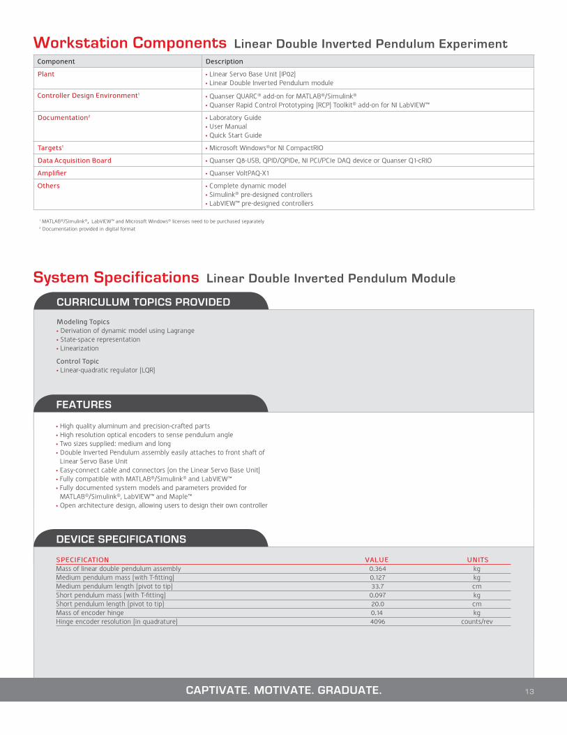
The Linear Double Inverted Pendulum experiment exposes students to the same modeling and balance control challenge found in the human posture system.
WWW.QUANSER.COM
“Hands-on experiments seem to be particularly
effective for teaching basic concepts in
dynamics and control. They are an attractive supple-
ment to rather conventional content of several courses.”
Shirley Dyke, Professor of Mechanical Engineering and Civil Engineering,
School of Civil Engineering, Purdue University, USA
CURRICULUM TOPICS PROVIDED
Modeling Topics• Derivation of dynamic model using Lagrange• State-space representation• Linearization
Control Topic• Linear-quadratic regulator (LQR)
FEATURES
• High quality aluminum and precision-crafted parts• High resolution optical encoders to sense pendulum angle • Two sizes supplied: medium and long• Double Inverted Pendulum assembly easily attaches to front shaft of
Linear Servo Base Unit• Easy-connect cable and connectors (on the Linear Servo Base Unit)• Fully compatible with MATLAB®/Simulink® and LabVIEW™• Fully documented system models and parameters provided for
MATLAB®/Simulink®, LabVIEW™ and Maple™• Open architecture design, allowing users to design their own controller
DEVICE SPECIFICATIONS
SPECIFICATION VALUE UNITSMass of linear double pendulum assembly 0.364 kgMedium pendulum mass (with T-fitting) 0.127 kgMedium pendulum length (pivot to tip) 33.7 cmShort pendulum mass (with T-fitting) 0.097 kgShort pendulum length (pivot to tip) 20.0 cmMass of encoder hinge 0.14 kgHinge encoder resolution (in quadrature) 4096 counts/rev
System Specifications Linear Double Inverted Pendulum Module
Component Description
Plant • Linear Servo Base Unit (IP02)• Linear Double Inverted Pendulum module
Controller Design Environment1 • Quanser QUARC® add-on for MATLAB®/Simulink®• Quanser Rapid Control Prototyping (RCP) Toolkit® add-on for NI LabVIEW™
Documentation2 • Laboratory Guide• User Manual• Quick Start Guide
Targets1 • Microsoft Windows®or NI CompactRIO
Data Acquisition Board • Quanser Q8-USB, QPID/QPIDe, NI PCI/PCIe DAQ device or Quanser Q1-cRIO
Amplifier • Quanser VoltPAQ-X1
Others • Complete dynamic model • Simulink® pre-designed controllers• LabVIEW™ pre-designed controllers
13
Workstation Components Linear Double Inverted Pendulum Experiment
CAPTIVATE. MOTIVATE. GRADUATE.
1 MATLAB®/Simulink®, LabVIEW™ and Microsoft Windows® licenses need to be purchased separately2 Documentation provided in digital format
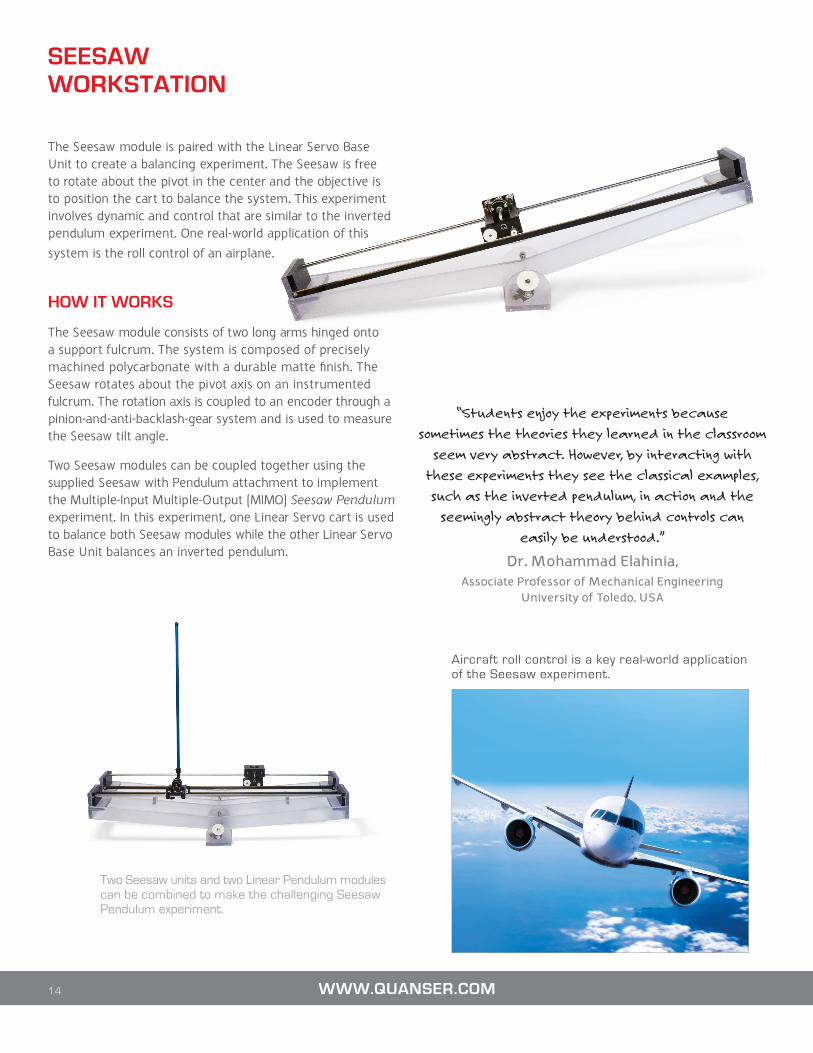
The Seesaw module is paired with the Linear Servo Base Unit to create a balancing experiment. The Seesaw is free to rotate about the pivot in the center and the objective is to position the cart to balance the system. This experiment involves dynamic and control that are similar to the inverted pendulum experiment. One real-world application of this
system is the roll control of an airplane.
HOW IT WORKS
The Seesaw module consists of two long arms hinged onto a support fulcrum. The system is composed of precisely machined polycarbonate with a durable matte finish. The Seesaw rotates about the pivot axis on an instrumented fulcrum. The rotation axis is coupled to an encoder through a pinion-and-anti-backlash-gear system and is used to measure the Seesaw tilt angle.
Two Seesaw modules can be coupled together using the supplied Seesaw with Pendulum attachment to implement the Multiple-Input Multiple-Output (MIMO) Seesaw Pendulum experiment. In this experiment, one Linear Servo cart is used to balance both Seesaw modules while the other Linear Servo Base Unit balances an inverted pendulum.
Aircraft roll control is a key real-world application of the Seesaw experiment.
SEESAW WORKSTATION
14 WWW.QUANSER.COM
Two Seesaw units and two Linear Pendulum modules can be combined to make the challenging Seesaw Pendulum experiment.
“Students enjoy the experiments because
sometimes the theories they learned in the classroom
seem very abstract. However, by interacting with
these experiments they see the classical examples,
such as the inverted pendulum, in action and the
seemingly abstract theory behind controls can
easily be understood.”
Dr. Mohammad Elahinia, Associate Professor of Mechanical Engineering
University of Toledo, USA
CURRICULUM TOPICS PROVIDED
Modeling Topics• Derivation of dynamic model using Lagrange• Linearization
Control Topics• State-space representation• Linear-quadratic regulator (LQR)
FEATURES
• High quality aluminum and precision-crafted parts• High resolution optical encoder to sense cart position• Easy-connect cables and connectors• Fully compatible with MATLAB®/Simulink® and LabVIEW™• Fully documented system models and parameters provided for
MATLAB®/Simulink®, LabVIEW™ and Maple™• Open architecture design, allowing users to design their own controller
Seesaw with Pendulum Module: • Supplied with each Seesaw module• Can be used to connect two Seesaws together to perform the Seesaw
Pendulum experiment
System Specifications Seesaw Module
DEVICE SPECIFICATIONS
SPECIFICATION VALUE UNITSDimensions (L x D x H) 112 x 20 x 40 cmMass of system (SEESAW and IP02 together) 3.6 kgPivot gear ratio 3Angle range about flat horizontal surface ±11.5 degDistance from pivot to IP02 track 12.5 cmDistance from pivot to COG 5.8 cmEncoder resolution (in quadrature) of pivot 4096 counts/rev
Workstation Components Seesaw Experiment Component Description
Plant • Linear Servo Base Unit (IP02)• Seesaw module
Controller Design Environment1 • Quanser QUARC® add-on for MATLAB®/Simulink®• Quanser Rapid Control Prototyping (RCP) Toolkit® add-on for NI LabVIEW™
Documentation2 • Laboratory Guide • User Manual• Quick Start Guide
Targets1 • Microsoft Windows® or NI CompactRIO
Data Acquisition Board • Quanser Q2-USB, Q8-USB, QPID/QPIDe, NI PCI/PCIe DAQ device or Quanser Q1-cRIO
Amplifier • Quanser VoltPAQ-X1
Others • Complete dynamic model • Simulink® pre-designed controllers• LabVIEW™ pre-designed controllers
TO REQUEST A QUOTE, PLEASE EMAIL [email protected] 15
1 MATLAB®/Simulink®, LabVIEW™ and Microsoft Windows® licenses need to be purchased separately2 Documentation provided in digital format
LINEAR FLEXIBLE JOINT WORKSTATION
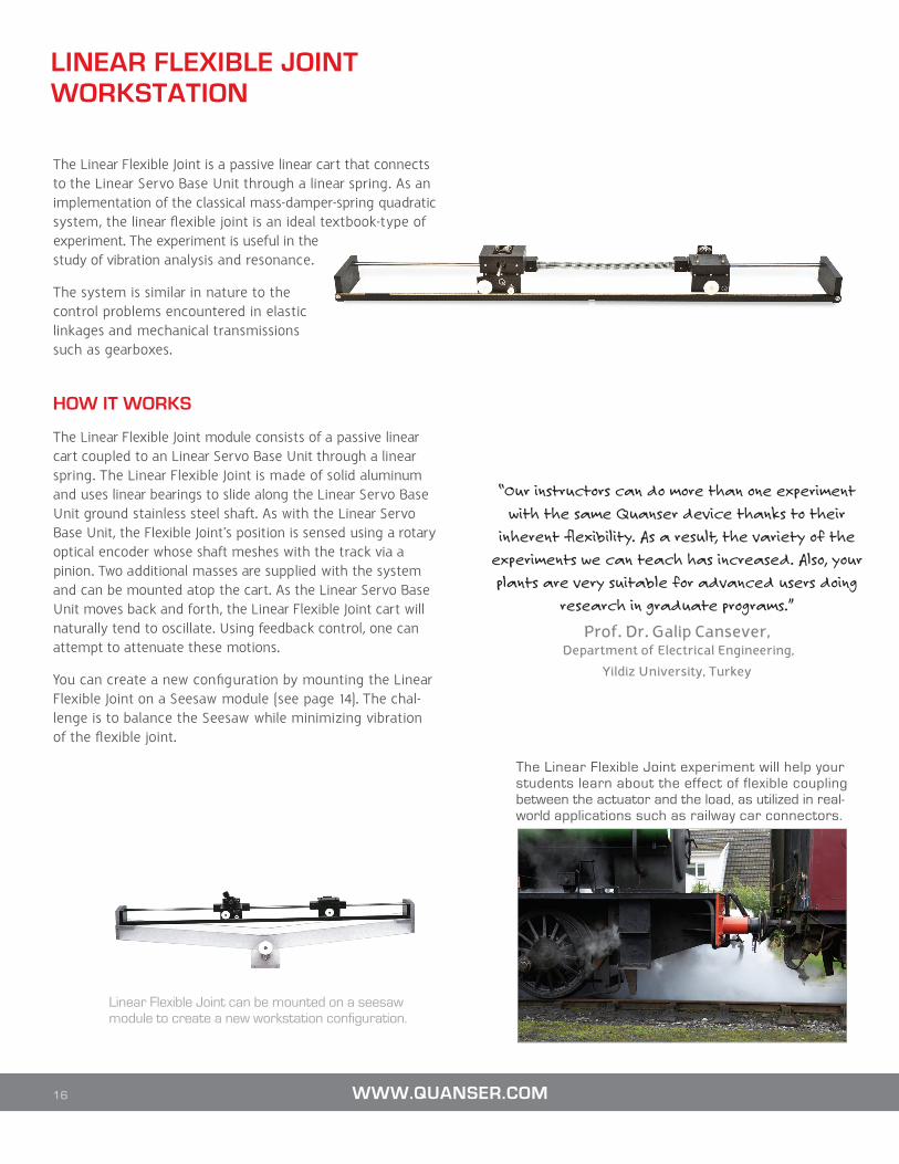
The Linear Flexible Joint is a passive linear cart that connects to the Linear Servo Base Unit through a linear spring. As an implementation of the classical mass-damper-spring quadratic system, the linear flexible joint is an ideal textbook-type of experiment. The experiment is useful in the study of vibration analysis and resonance.
The system is similar in nature to the control problems encountered in elastic linkages and mechanical transmissions such as gearboxes.
HOW IT WORKS
The Linear Flexible Joint module consists of a passive linear cart coupled to an Linear Servo Base Unit through a linear spring. The Linear Flexible Joint is made of solid aluminum and uses linear bearings to slide along the Linear Servo Base Unit ground stainless steel shaft. As with the Linear Servo Base Unit, the Flexible Joint’s position is sensed using a rotary optical encoder whose shaft meshes with the track via a pinion. Two additional masses are supplied with the system and can be mounted atop the cart. As the Linear Servo Base Unit moves back and forth, the Linear Flexible Joint cart will naturally tend to oscillate. Using feedback control, one can attempt to attenuate these motions.
You can create a new configuration by mounting the Linear Flexible Joint on a Seesaw module (see page 14). The chal-lenge is to balance the Seesaw while minimizing vibration of the flexible joint.
16 WWW.QUANSER.COM
The Linear Flexible Joint experiment will help your students learn about the effect of flexible coupling between the actuator and the load, as utilized in real-world applications such as railway car connectors.
“Our instructors can do more than one experiment
with the same Quanser device thanks to their
inherent flexibility. As a result, the variety of the
experiments we can teach has increased. Also, your
plants are very suitable for advanced users doing
research in graduate programs.”
Prof. Dr. Galip Cansever, Department of Electrical Engineering,
Yildiz University, Turkey
Linear Flexible Joint can be mounted on a seesaw module to create a new workstation configuration.
CURRICULUM TOPICS PROVIDED
Modeling Topics• Derivation of dynamic model using Lagrange• State-space representation• Parameter estimation• Model validation
Control Topics• Linear-quadratic regulator (LQR)• Vibration control
FEATURES
• High quality aluminum and precision-crafted parts• High resolution optical encoder to sense cart position• Easy-connect cables and connectors• Fully compatible with MATLAB®/Simulink® and LabVIEW™• Fully documented system models and parameters provided for
MATLAB®/Simulink®, LabVIEW™ and Maple™• Open architecture design, allowing users to design their own controller
System Specifications Linear Flexible Joint Module
DEVICE SPECIFICATIONS
SPECIFICATION VALUE UNITSLinear Flexible Joint cart (LFJC) mass 0.22 kgLFJC weight mass 0.13 kgLFJC dimensions (L x D x H) 10 x 14 x 12 cmSpring stiffness 142 N/mSpring assembly mass 0.145 kgSpring length 29.0 cmLFJC encoder resolution (in quadrature) 4096 counts/revLFJC with Pendulum option: pendulum encoder resolution (in quadrature) 4096 counts/rev
Workstation Components Linear Flexible Joint ExperimentComponent Description
Plant • Linear Servo Base Unit (IP02)• Linear Flexible Joint module
Controller Design Environment1 • Quanser QUARC® add-on for MATLAB®/Simulink®• Quanser Rapid Control Prototyping (RCP) Toolkit® add-on for NI LabVIEW™
Documentation2 • ABET-aligned* Instructor Workbook • ABET-aligned* Student Workbook• User Manual• Quick Start Guide
Targets1 • Microsoft Windows® or NI CompactRIO
Data Acquisition Board • Quanser Q2-USB, Q8-USB, QPID/QPIDe, NI PCI/PCIe DAQ device or Quanser Q1-cRIO
Amplifier • Quanser VoltPAQ-X1
Others • Complete dynamic model • Simulink® pre-designed controllers• LabVIEW™ pre-designed controllers
17CAPTIVATE. MOTIVATE. GRADUATE.
1 MATLAB®/Simulink®, LabVIEW™ and Microsoft Windows® licenses need to be purchased separately2 Documentation provided in digital format
* ABET, Inc., is the recognized accreditor for college and university programs in applied science, computing, engineering, and technology
LINEAR FLEXIBLE JOINT WITH INVERTED PENDULUM WORKSTATION
The Linear Flexible Joint with Inverted Pendulum is similar to the Linear Flexible Joint experiment. It is ideal to introduce intermediate control concepts related to vibration analysis and resonance, encountered, for example, in elastic linkages and mechanical transmissions.
The experiment challenges students to design a state-feed-back control system that can balance an inverted pendulum mounted on the linear flexible joint cart, while minimizing the spring deflection.
HOW IT WORKS
The Linear Flexible Joint with Inverted Pendulum consists of a Linear Flexible Joint module with a passive linear cart coupled to a Linear Servo Base Unit through a linear spring and a pendulum mounted on the output cart.
The Linear Flexible Joint is made of solid aluminum and uses linear bearings to slide along the Linear Servo Base Unit ground stainless steel shaft. The cart position is measured using a rotary optical encoder whose shaft meshes with the track via a pinion. The system is supplied with two additional masses that can be mounted atop the cart.
As the Linear Servo Base Unit moves back and forth, the Linear Flexible Joint cart will naturally tend to oscillate. Using feedback control, one can attempt to attenuate these motions.
The passive cart is equipped with a rotary joint, the joint’s axis of rotation is perpendicular to the direction of the cart’s motion. A free-swinging rod can be attached to the joint, suspended in front of the cart. This rod can function as an inverted pendulum, as well as a regular pendulum. The angle of the rod is measured using a rotary optical encoder
Two different pendulum rods are supplied: a 12-inch “medium” pendulum and a 24-inch “long” pendulum.
18 WWW.QUANSER.COM
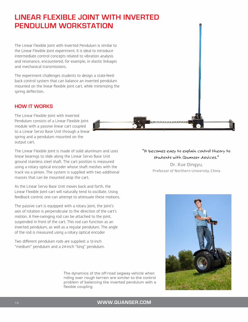
The dynamics of the off-road segway vehicle when riding over rough terrain are similar to the control problem of balancing the inverted pendulum with a flexible coupling.
“It becomes easy to explain control theory to
students with Quanser devices.”
Dr. Xue Dingyu,Professor of Northern University, China
CURRICULUM TOPICS PROVIDED
Modeling Topics• Derivation of dynamic model using Lagrange• State-space representation• Parameter estimation• Model validation
Control Topics• Linear-quadratic regulator (LQR)• Vibration control
FEATURES
• High quality aluminum and precision-crafted parts• High resolution optical encoder to sense cart position and pendulum
angle• Pendulum easily attaches to front shaft of Flexible Joint module• Two different pendulum lengths supplied• Fully compatible with MATLAB®/Simulink® and LabVIEW™• Fully documented system models and parameters provided for
MATLAB®/Simulink®, LabVIEW™ and Maple™• Open architecture design, allowing users to design their own controller
System Specifications Linear Flexible Joint with Inverted Pendulum
DEVICE SPECIFICATIONS
SPECIFICATION VALUE UNITSLinear Flexible Joint cart with Inverted Pendulum mass mass 0.24 kgWeight mass 0.12 kgPendulum fixture mass 0.135 kgSpring stiffness 160 N/mSpring assembly mass 0.145 kgSpring length 29.0 cmLong pendulum length (from pivot to tip) 64.1 cmLong pendulum mass (with T-fitting) 0.23 kgMedium pendulum length (from pivot to tip) 33.6 cmMedium pendulum mass (with T-fitting) 0.127 kgCart encoder resolution (in quadrature) 4096 counts/revPendulum encoder resolution (in quadrature) 4096 counts/rev
Workstation Components Linear Flexible Joint with Inverted Pendulum ExperimentComponent Description
Plant • Linear Servo Base Unit (IP02)• Linear Flexible Joint with Inverted Pendulum module
Controller Design Environment1 • Quanser QUARC® add-on for MATLAB®/Simulink®• Quanser Rapid Control Prototyping (RCP) Toolkit® add-on for NI LabVIEW™
Documentation2 • Laboratory Guide • User Manual• Quick Start Guide
Targets1 • Microsoft Windows® or NI CompactRIO
Data Acquisition Board • Quanser Q8-USB, QPID/QPIDe, NI PCI/PCIe DAQ device or Quanser Q1-cRIO
Amplifier • Quanser VoltPAQ-X1
Others • Complete dynamic model • Simulink® pre-designed controllers• LabVIEW™ pre-designed controllers
19TO REQUEST A QUOTE, PLEASE EMAIL [email protected]
1 MATLAB®/Simulink®, LabVIEW™ and Microsoft Windows® licenses need to be purchased separately2 Documentation provided in digital format

University of Toronto • Monash University • Kyoto University
University of Manchester • California Institute of Technology
Polytechnic School of Lausanne • Hong Kong University of Science and Technology
University of Waterloo • Carnegie Mellon University
University of Melbourne • ETH Zurich • Yale University
University of Houston • KAIST • Karlsruhe University
of Alberta • Gifu University • Loughborough University
University of California, Berkeley • KTH • McMaster University
University Munich • Rice University • Kyoto Institute of Technology
University of Auckland • MIT • Imperial College London
The Chinese University of Hong Kong • Virginia Tech
of Cincinnati • McGill University • Australian National University
University of Bristol • Purdue University • Osaka University
King Soud University • I.I.T Kharagpur •Memorial University
University of British Columbia • Delft University of Technology
University of Texas at Austin • Beijing Institute of Technology
of Tokyo • Princeton University • Hebei University of Technology
University of Wisconsin-Madison • Holon Institute of Technology
of Klagenfurt • Harvard University • Tokyo Institute of Technology
University of Reading • Tsinghua University • Cornell University
University of Michigan • Korea University • Queen’s University
University of Stuttgart • Georgia Tech • Ben-Gurion University
University Eindhoven • Ajou University • Kobe University
University of Maryland College Park • Nanyang Technological University
University of New South Wales • Washington University in St.Louis
National University of Singapore • Harbin Institute of Technology
University of Victoria • Boston University • Donghua University
Northwestern University • Tongji University • Royal Military College
University of Quebec • Clemson University • Fukuoka University
Adelaide University • University of Barcelona • SUNY
Queen’s University Belfast •Istanbul Technical University
de Los Andes • Louisiana Tech • Norwegian University of Science and Technology
United States Military Academy • CINVESTAV • Drexel University
YOU CAN RELY ON QUANSER TO ADVANCE CONTROL EDUCATION
For over two decades Quanser has focused solely on the development of
solutions for control education and research. Today, over 2,500 universities,
colleges and research institutions around the world rely on Quanser
control systems to attract and motivate engineering students or to
advance innovation.
Our Linear Motion Control solutions offer quality, convenience, ease of use,
ongoing technical support and affordability. They are part of a wider range
of Quanser control lab solutions designed to enhance students’ academic
experience. They come as complete workstations and can captivate
undergraduate and graduate students, motivate them to study further
and encourage them to innovate.
Engineering educators worldwide agree that Quanser workstations are
reliable and robust. Choose from a variety of mechatronics experiments
and control design tools appropriate for teaching at all levels as well as
advanced research. Take advantage of engineering expertise that includes
mechatronics, electronics, software development and control system
design. Leverage the accompanying ABET*-aligned courseware which
have been developed to the highest academic standards. Last but not least,
rely on Quanser’s engineers for ongoing technical support as your teaching
or research requirements evolve over time.
Learn more at www.quanser.com or contact us at [email protected]
Follow us on:
*ABET, is the recognized accreditor for college and university programs in applied science, computing, engineering, and technology.
Products and/or services pictured and referred to herein and their accompanying specifications may be subject to change without notice. Products and/or services mentioned herein are trademarks or registered trademarks of Quanser Inc. and/or its affiliates. MATLAB® and Simulink® are registered trademarks of The MathWorks Inc. LabVIEW™ is a trademark of the National Instruments. Windows® is a registered trademark of the Microsoft. Other product and company names mentioned herein are trademarks or registered trademarks of their respective owners. ©2013 Quanser Inc. All rights reserved. Ver 1.0