Embed Size (px)
Citation preview
Market Information MAI 92
double row!
New series,
including rolle
r chain
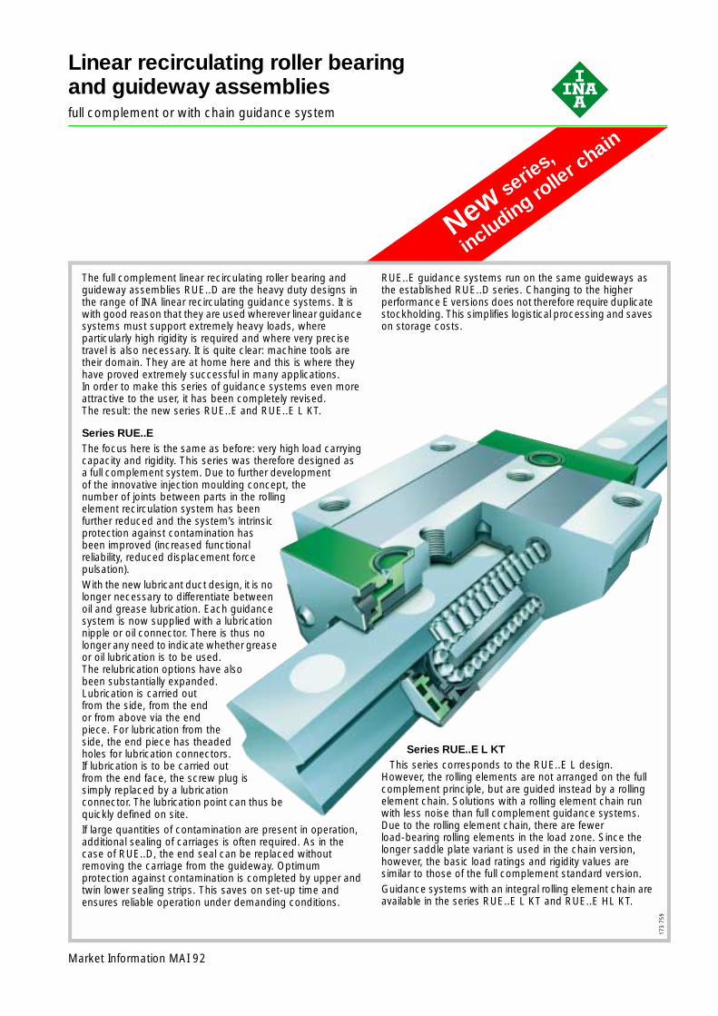
Linear recirculating roller bearingand guideway assembliesfull complement or with chain guidance system
The full complement linear recirculating roller bearing and guideway assemblies RUE..D are the heavy duty designs in the range of INA linear recirculating guidance systems. It is with good reason that they are used wherever linear guidance systems must support extremely heavy loads, where particularly high rigidity is required and where very precise travel is also necessary. It is quite clear: machine tools are their domain. They are at home here and this is where they have proved extremely successful in many applications. In order to make this series of guidance systems even more attractive to the user, it has been completely revised. The result: the new series RUE..E and RUE..E L KT.
Series RUE..EThe focus here is the same as before: very high load carrying capacity and rigidity. This series was therefore designed as a full complement system. Due to further development of the innovative injection moulding concept, the number of joints between parts in the rolling element recirculation system has been further reduced and the system’s intrinsic protection against contamination has been improved (increased functional reliability, reduced displacement force pulsation).With the new lubricant duct design, it is no longer necessary to differentiate between oil and grease lubrication. Each guidance system is now supplied with a lubrication nipple or oil connector. There is thus no longer any need to indicate whether grease or oil lubrication is to be used. The relubrication options have also been substantially expanded. Lubrication is carried out from the side, from the end or from above via the end piece. For lubrication from the side, the end piece has theaded holes for lubrication connectors. If lubrication is to be carried out from the end face, the screw plug is simply replaced by a lubrication connector. The lubrication point can thus be quickly defined on site.If large quantities of contamination are present in operation, additional sealing of carriages is often required. As in the case of RUE..D, the end seal can be replaced without removing the carriage from the guideway. Optimum protection against contamination is completed by upper and twin lower sealing strips. This saves on set-up time and ensures reliable operation under demanding conditions.
173
759
RUE..E guidance systems run on the same guideways as the established RUE..D series. Changing to the higher performance E versions does not therefore require duplicate stockholding. This simplifies logistical processing and saves on storage costs.
Series RUE..E L KTThis series corresponds to the RUE..E L design.
However, the rolling elements are not arranged on the full complement principle, but are guided instead by a rolling element chain. Solutions with a rolling element chain run with less noise than full complement guidance systems. Due to the rolling element chain, there are fewerload-bearing rolling elements in the load zone. Since the longer saddle plate variant is used in the chain version, however, the basic load ratings and rigidity values are similar to those of the full complement standard version.Guidance systems with an integral rolling element chain are available in the series RUE..E L KT and RUE..E HL KT.
2
Linear recirculatingroller bearingand guideway assembliesfull complement
Page
Preload ................................................................ 5
Friction ................................................................. 5
Accuracy.............................................................. 5
Demands on the adjacent construction .............. 8
Ordering example and ordering designation ....... 10
Features
Linear recirculating roller bearingand guideway assemblies■ are complete units comprising:
– at least one carriage RWU..E with a full complement cylindrical roller system
– a guideway TSX..E (U) with two locating edges– integral elastic wipers on the end faces of the carriage
and upper as well as twin lower sealing strips– plastic closing plugs
■ can support loads from all directions – apart from the direction of motion – and moments about all axes
■ are preloaded– the preload is determined by the carriage
■ have, due to further development of the patented injection moulding technology– fewer joints and transitions– precise guidance of the rolling elements by ribs and
therefore very high running accuracy– a device for retaining the rollers in order to allow easy
fitting of the carriage■ are supplied with lubrication nipples and oil connectors
– the lubrication nipples can be screwed into the right, the left or the end face of the end piece; before they are screwed in, the lateral lubrication hole in the end piece must first be opened using a pointed object
■ are supplied with multi-piece guideways if the required guideway length is in excess of the maximum length lmax according to the dimension table
■ are suitable for:– accelerations up to 100 m/s2
– speeds up to 180 m/min– operating temperatures from –10 °C to +100 °C
■ are used in applications with:– long, unlimited stroke lengths– high and very high loads– high and very high rigidity.
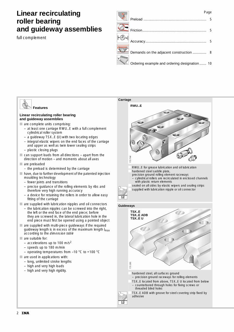
Carriage
■ RWU..E for grease lubrication and oil lubrication■ hardened steel saddle plate,
precision ground rolling element raceways– cylindrical rollers are recirculated in enclosed channels
with plastic return elements■ sealed on all sides by elastic wipers and sealing strips■ supplied with lubrication nipple or oil connector
Guideways
■ hardened steel, all surfaces ground– precision ground raceways for rolling elements
■ TSX..E located from above, TSX..E U located from below– counterbored through holes for fixing screws or
threaded blind holes■ TSX..E ADB with groove for steel covering strip fixed by
adhesive
RWU..E
173
744
TSX..ETSX..E ADBTSX..E U
173
205
12
12
3
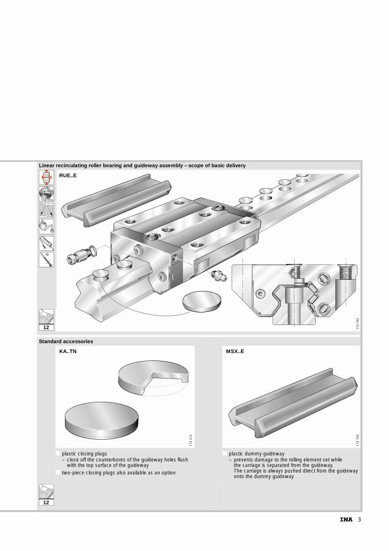
Linear recirculating roller bearing and guideway assembly – scope of basic delivery
k0M
˚C
■ ■ ■Standard accessories
■ plastic closing plugs– close off the counterbores of the guideway holes flush
with the top surface of the guideway■ two-piece closing plugs also available as an option
■ plastic dummy guideway– prevents damage to the rolling element set while
the carriage is separated from the guideway. The carriage is always pushed direct from the guideway onto the dummy guideway
RUE..E
173
742
173
212
KA..TN17
3 74
3
MSX..E
12
12
4
Linear recirculating roller bearing and guideway assemblies
full complement
Features
InterchangeabilityThe carriage and guideway of a linear recirculating roller bearing and guideway assembly are matched to each other as a standard system due to their closely toleranced preload.It may be possible, after consultation, to use carriages and guideways in different combinations.
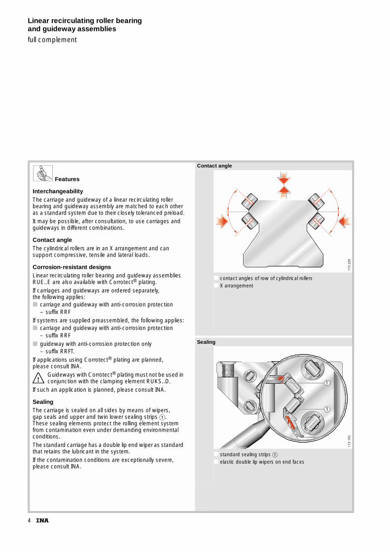
Contact angleThe cylindrical rollers are in an X arrangement and can support compressive, tensile and lateral loads.
Corrosion-resistant designsLinear recirculating roller bearing and guideway assemblies RUE..E are also available with Corrotect® plating.If carriages and guideways are ordered separately, the following applies:■ carriage and guideway with anti-corrosion protection
– suffix RRFIf systems are supplied preassembled, the following applies:■ carriage and guideway with anti-corrosion protection
– suffix RRF■ guideway with anti-corrosion protection only
– suffix RRFT.If applications using Corrotect® plating are planned, please consult INA.
Guideways with Corrotect® plating must not be used in conjunction with the clamping element RUKS..D.
If such an application is planned, please consult INA.
SealingThe carriage is sealed on all sides by means of wipers, gap seals and upper and twin lower sealing strips �. These sealing elements protect the rolling element system from contamination even under demanding environmental conditions.The standard carriage has a double lip end wiper as standard that retains the lubricant in the system.If the contamination conditions are exceptionally severe, please consult INA.
Contact angle
■ contact angles of row of cylindrical rollers■ X arrangement
Sealing
■ standard sealing strips �■ elastic double lip wipers on end faces
173
209
1
1
173
745
5
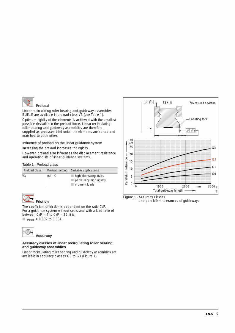
PreloadLinear recirculating roller bearing and guideway assemblies RUE..E are available in preload class V3 (see Table 1).Optimum rigidity of the elements is achieved with the smallest possible deviation in the preload force. Linear recirculating roller bearing and guideway assemblies are therefore supplied as preassembled units; the elements are sorted and matched to each other.
Influence of preload on the linear guidance systemIncreasing the preload increases the rigidity.However, preload also influences the displacement resistance and operating life of linear guidance systems.
FrictionThe coefficient of friction is dependent on the ratio C/P. For a guidance system without seals and with a load ratio of between C/P = 4 to C/P = 20, it is:■ �RUE = 0,002 to 0,004.
Accuracy
Accuracy classes of linear recirculating roller bearing and guideway assembliesLinear recirculating roller bearing and guideway assemblies are available in accuracy classes G0 to G3 (Figure 1).
Figure 1 · Accuracy classesand parallelism tolerances of guideways
Table 1 · Preload class
Preload class Preload setting Suitable applications
V3 0,1 · C ■ high alternating loads■ particularly high rigidity■ moment loads
30
25
20t
Par
alle
lism
tole
ranc
e
15
10
5
00
1000 mmTotal guideway length
3000
G1
G2
G0
G3
2000
m�
5t )
5t )
TSX..E )5 Measured deviation
Locating face
173
746
6
Linear recirculating roller bearing and guideway assemblies
full complement
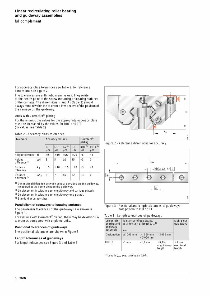
For accuracy class tolerances see Table 2, for reference dimensions see Figure 2.The tolerances are arithmetic mean values. They relate to the centre point of the screw mounting or locating surfaces of the carriage. The dimensions H and A1 (Table 2) should always remain within the tolerance irrespective of the position of the carriage on the guideway.
Units with Corrotect® platingFor these units, the values for the appropriate accuracy class must be increased by the values for RRF or RRFT(for values see Table 2).
1) Dimensional difference between several carriages on one guideway, measured at the same point on the guideway.
2) Displacement in tolerance zone (guideway and carriage plated).3) Displacement in tolerance zone (guideway only plated).4) Standard accuracy class.
Parallelism of raceways to locating surfacesThe parallelism tolerances of the guideways are shown in Figure 1.For systems with Corrotect® plating, there may be deviations in tolerances compared with unplated units.
Positional tolerances of guidewaysThe positional tolerances are shown in Figure 3.
Length tolerances of guidewaysFor length tolerances see Figure 3 and Table 3.
Figure 2 · Reference dimensions for accuracy
Figure 3 · Positional and length tolerances of guideways –hole pattern to ISO 1101
1) Length lmax see: dimension table.
Table 2 · Accuracy class tolerances
Tolerance Accuracy classes Corrotect® plating
G0�m
G1�m
G24)
�mG3�m
RRF2)
�mRRFT3)
�m
Height tolerance H �5 �10 �20 �25 +6 +3
Height difference1)
�H 3 5 10 15 +3 0
Distance tolerance
A1 �5 �10 �15 �20 +3 +3
Distance difference1)
�A1 3 7 15 22 +3 0
Table 3 · Length tolerances of guideways
Linear roller bearing and guideway assembly
Tolerances of guideways,as a function of length lmax
1)
lmax
Multi-piece guideways
Designation �1000 mm �1000 mm�3 000 mm
�3 000 mm
RUE..E –1 mm –1,5 mm �0,1%of guideway length
�3 mmover total length
H
A1
173
747
b/2
� 0,4 n�
l max
jL
jL
173
214
7
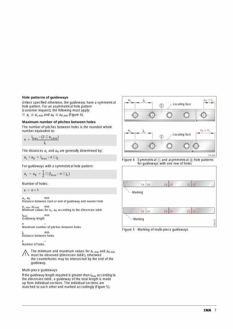
Hole patterns of guidewaysUnless specified otherwise, the guideways have a symmetrical hole pattern. For an asymmetrical hole pattern (customer request), the following must apply:■ aL aL min and aR aR min (Figure 4).
Maximum number of pitches between holesThe number of pitches between holes is the rounded whole number equivalent to:
The distances aL and aR are generally determined by:
For guideways with a symmetrical hole pattern:
Number of holes:
aL, aR mmDistance between start or end of guideway and nearest hole
aL min, aR min mmMinimum values for aL, aR according to the dimension table
lmax mmGuideway length
n –Maximum number of pitches between holes
jL mmDistance between holes
x –Number of holes.
The minimum and maximum values for aL min and aR min must be observed (dimension table), otherwise the counterbores may be intersected by the end of the guideway.
Multi-piece guidewaysIf the guideway length required is greater than lmax according to the dimension table, a guideway of the total length is made up from individual sections. The individual sections are matched to each other and marked accordingly (Figure 5).
Figure 4 · Symmetrical � and asymmetrical � hole patterns for guideways with one row of holes
Figure 5 · Marking of multi-piece guideways
nlmax 2 aLmin⋅( )–
jL----------------------------------------------=
aL aR+ lmax n jL⋅–=
aL aR12--- lmax n jL⋅–( )⋅= =
x n 1+=
aaa R LL
a L
=jL
jL
2
1
aaR L
Locating face
Locating face
173 220
1A 1B 1C
2A 2B 2C
1A 1B 1C
2A 2B 2C
Marking
Marking
156
211
8
Linear recirculating roller bearing and guideway assemblies
full complement
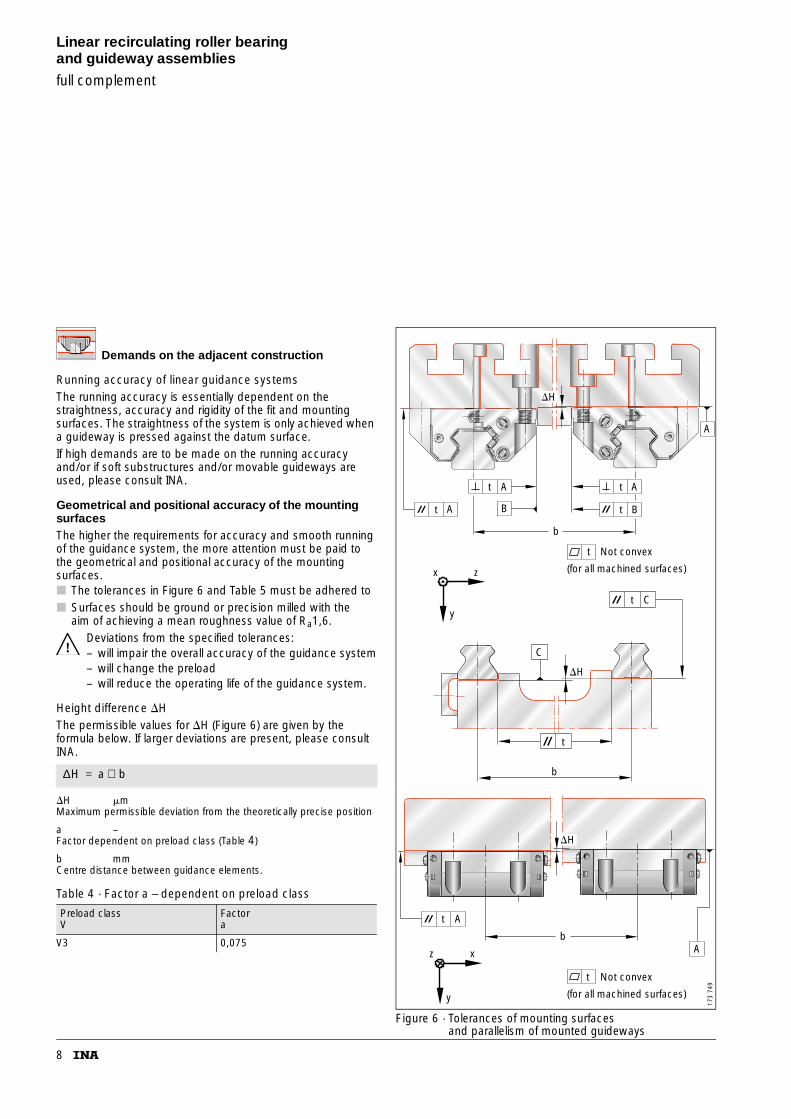
Demands on the adjacent construction
Running accuracy of linear guidance systemsThe running accuracy is essentially dependent on the straightness, accuracy and rigidity of the fit and mounting surfaces. The straightness of the system is only achieved when a guideway is pressed against the datum surface.If high demands are to be made on the running accuracyand/or if soft substructures and/or movable guideways are used, please consult INA.
Geometrical and positional accuracy of the mounting surfacesThe higher the requirements for accuracy and smooth running of the guidance system, the more attention must be paid to the geometrical and positional accuracy of the mounting surfaces.■ The tolerances in Figure 6 and Table 5 must be adhered to■ Surfaces should be ground or precision milled with the
aim of achieving a mean roughness value of Ra1,6.Deviations from the specified tolerances:– will impair the overall accuracy of the guidance system– will change the preload– will reduce the operating life of the guidance system.
Height difference �HThe permissible values for �H (Figure 6) are given by the formula below. If larger deviations are present, please consult INA.
�H �mMaximum permissible deviation from the theoretically precise position
a –Factor dependent on preload class (Table 4)
b mmCentre distance between guidance elements.
Figure 6 · Tolerances of mounting surfacesand parallelism of mounted guideways
Table 4 · Factor a – dependent on preload class
Preload classV
Factora
V3 0,075
∆H a b⋅=
A
AA
B BA
b
A
Ab
z x
y
x z
y
t
t
t
t
t
t
t
�H
�H
�H
Not convex
(for all machined surfaces)
C
t
b
t C
Not convex
(for all machined surfaces)
173
749
9
Parallelism of mounted guidewaysFor guideways arranged parallel to each other, the parallelism value t in Figure 6 and Table 5 should be adhered to.If the maximum values are used, this may increase the displacement resistance. If larger tolerances are present, please consult INA.
Locating heights and corner radiiLocating heights and corner radii should be in accordance with Figure 7 and Table 6.
Figure 7 · Locating heights and corner radii
Table 5 · Values for parallelism tolerances t
GuidewayDesignation
Preload class
V3
Parallelism tolerance
t�m
TSX 35 E (U) 10
TSX 45 E (U) 10
Table 6 · Locating heights and corner radii
Linear roller bearingand guideway assemblyDesignation
h1 h2max.
r1max.
r2max.
RUE 35 E (L, H, HL) 8 6 1 0,8
RUE 45 E (L, H, HL) 10 8 1 0,8
r
h
1
1
r2h2
173
748
10
Linear recirculating roller bearing and guideway assemblies
full complement
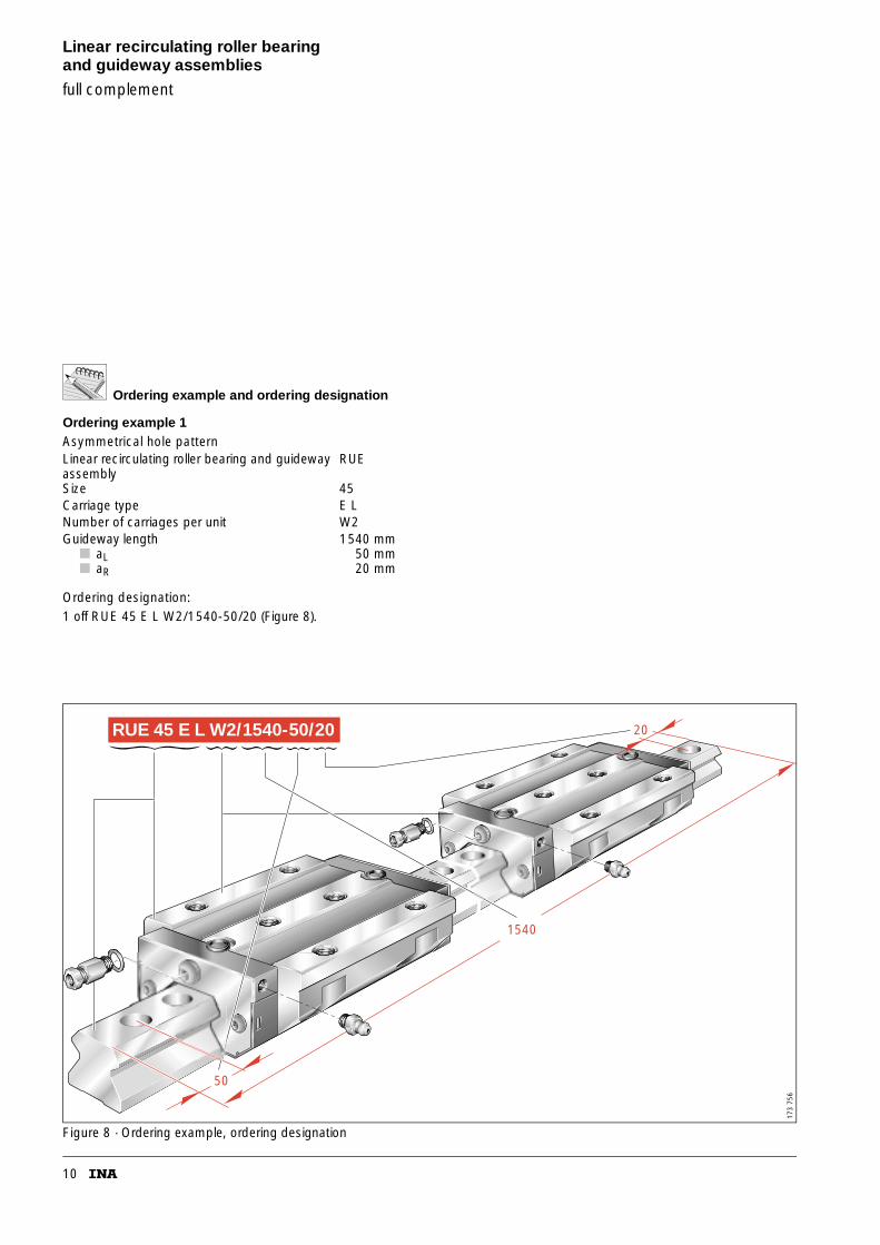
Ordering example and ordering designation
Ordering example 1Asymmetrical hole pattern
Ordering designation:1 off RUE 45 E L W2/1540-50/20 (Figure 8).
Figure 8 · Ordering example, ordering designation
Linear recirculating roller bearing and guideway assembly
RUE
Size 45Carriage type E LNumber of carriages per unit W2Guideway length 1540 mm
■ aL■ aR
50 mm20 mm
20
1540
RUE 45 E L W2/1540-50/20
50
173
756
11
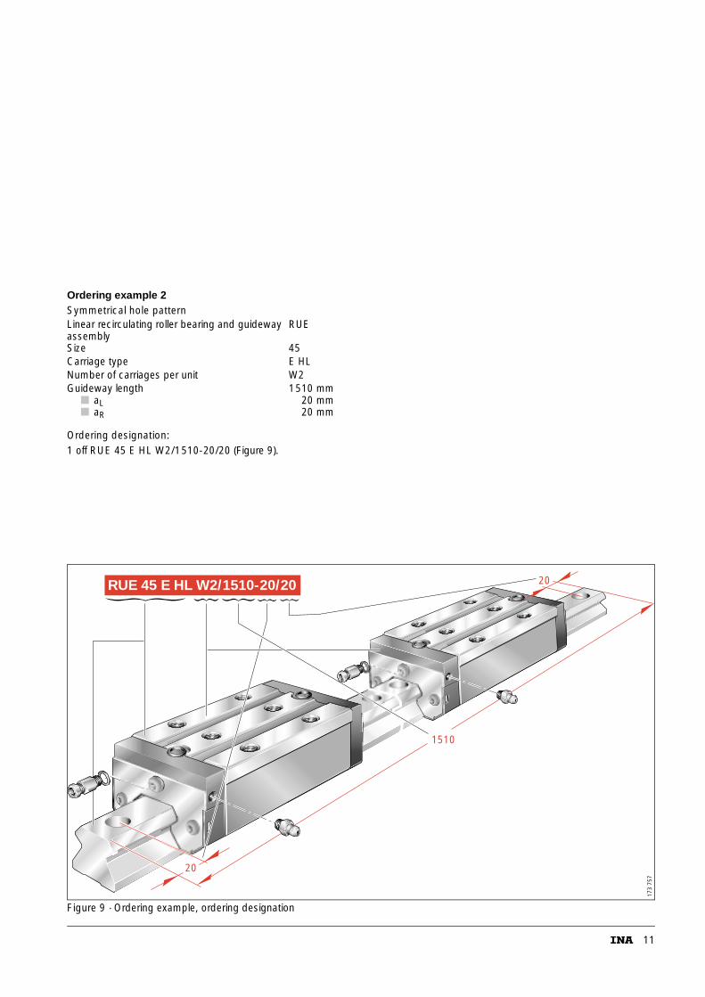
Ordering example 2Symmetrical hole pattern
Ordering designation:1 off RUE 45 E HL W2/1510-20/20 (Figure 9).
Figure 9 · Ordering example, ordering designation
Linear recirculating roller bearing and guideway assembly
RUE
Size 45Carriage type E HLNumber of carriages per unit W2Guideway length 1510 mm
■ aL■ aR
20 mm20 mm
1510
RUE 45 E HL W2/1510-20/20
20
20
173
757
12
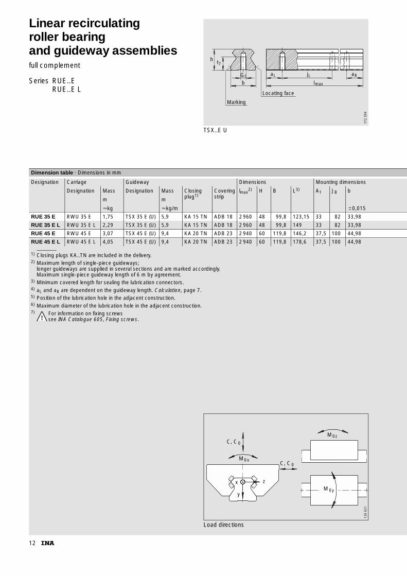
Linear recirculatingroller bearingand guideway assembliesfull complement
Series RUE..ERUE..E L
TSX..E U
Marking
Locating face
l
aRjLaL
bG1
h t7
max
172
394
1) Closing plugs KA..TN are included in the delivery.2) Maximum length of single-piece guideways;
longer guideways are supplied in several sections and are marked accordingly.Maximum single-piece guideway length of 6 m by agreement.
3) Minimum covered length for sealing the lubrication connectors.4) aL and aR are dependent on the guideway length. Calculation, page 7.5) Position of the lubrication hole in the adjacent construction.6) Maximum diameter of the lubrication hole in the adjacent construction.7) For information on fixing screws
see INA Catalogue 605, Fixing screws.
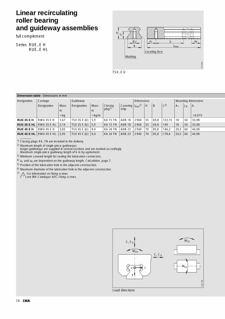
Dimension table · Dimensions in mm
Designation Carriage Guideway Dimensions Mounting dimensions
Designation Mass Designation Mass Closing plug1)
Covering strip
lmax2) H B L3) A1 JB b
m m
�kg �kg/m �0,015
RUE 35 E RWU 35 E 1,75 TSX 35 E (U) 5,9 KA 15 TN ADB 18 2 960 48 99,8 123,15 33 82 33,98
RUE 35 E L RWU 35 E L 2,29 TSX 35 E (U) 5,9 KA 15 TN ADB 18 2 960 48 99,8 149 33 82 33,98
RUE 45 E RWU 45 E 3,07 TSX 45 E (U) 9,4 KA 20 TN ADB 23 2 940 60 119,8 146,2 37,5 100 44,98
RUE 45 E L RWU 45 E L 4,05 TSX 45 E (U) 9,4 KA 20 TN ADB 23 2 940 60 119,8 178,6 37,5 100 44,98
Load directions
C, C0
M0xC, C0
M0z
M 0y
x
y
z
126
621
13
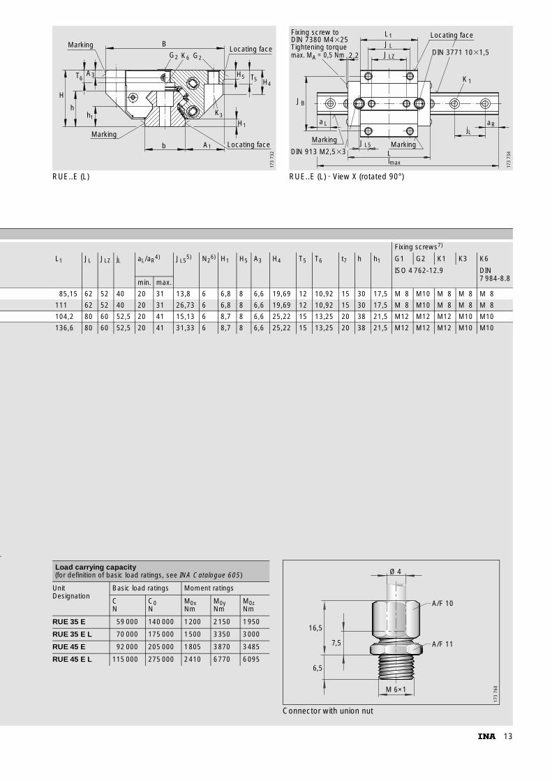
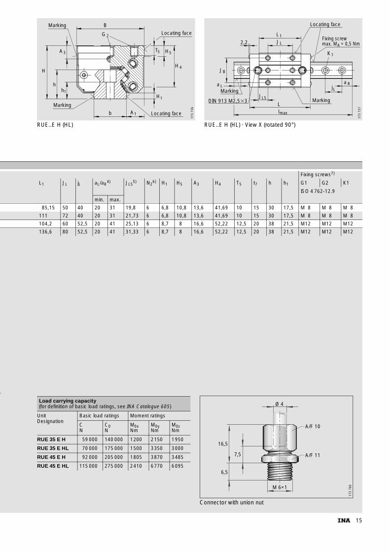
RUE..E (L) RUE..E (L) · View X (rotated 90°)
Marking
Marking
hh
T
H
6
1
3
Locating faceb A1
B
G2K6G2Locating face
H
H5 T5 H4
1
K3
A
173
732
max. M = 0,5 NmA
Marking
max
Marking
Locating face
2,2
L1JL
JLZ
JB
a L
JL5
Ll
K1
jLaR
DIN 913 M2,5�3
Fixing screw to DIN 7380 M4�25Tightening torque
DIN 3771 10�1,5
173
734
az
Fixing screws7)
L1 JL JLZ jL aL/aR4) JL5
5) N26) H1 H5 A3 H4 T5 T6 t7 h h1 G1 G2 K1 K3 K6
ISO 4 762-12.9 DIN 7 984-8.8min. max.
85,15 62 52 40 20 31 13,8 6 6,8 8 6,6 19,69 12 10,92 15 30 17,5 M 8 M10 M 8 M 8 M 8
111 62 52 40 20 31 26,73 6 6,8 8 6,6 19,69 12 10,92 15 30 17,5 M 8 M10 M 8 M 8 M 8
104,2 80 60 52,5 20 41 15,13 6 8,7 8 6,6 25,22 15 13,25 20 38 21,5 M12 M12 M12 M10 M10
136,6 80 60 52,5 20 41 31,33 6 8,7 8 6,6 25,22 15 13,25 20 38 21,5 M12 M12 M12 M10 M10
Connector with union nut
Load carrying capacity(for definition of basic load ratings, see INA Catalogue 605)
UnitDesignation
Basic load ratings Moment ratings
CN
C0N
M0xNm
M0yNm
M0zNm
RUE 35 E 59 000 140 000 1200 2150 1950
RUE 35 E L 70 000 175 000 1500 3350 3000
RUE 45 E 92 000 205 000 1805 3870 3485
RUE 45 E L 115 000 275 000 2410 6770 6095
16,5
6,5
7,5
M 6×1
Ø 4
A/F 10
A/F 11
173
760
14
Linear recirculatingroller bearingand guideway assembliesfull complement
Series RUE..E HRUE..E HL
TSX..E U
Marking
Locating face
l
aRjLaL
bG1
h t7
max
172
394
1) Closing plugs KA..TN are included in the delivery.2) Maximum length of single-piece guideways;
longer guideways are supplied in several sections and are marked accordingly.Maximum single-piece guideway length of 6 m by agreement.
3) Minimum covered length for sealing the lubrication connectors.4) aL and aR are dependent on the guideway length. Calculation, page 7.5) Position of the lubrication hole in the adjacent construction.6) Maximum diameter of the lubrication hole in the adjacent construction.7) For information on fixing screws
see INA Catalogue 605, Fixing screws.
Dimension table · Dimensions in mm
Designation Carriage Guideway Dimensions Mounting dimensions
Designation Mass Designation Mass Closing plug1)
Covering strip
lmax2) H B L3) A1 JB b
m m
�kg �kg/m �0,015
RUE 35 E H RWU 35 E H 1,67 TSX 35 E (U) 5,9 KA 15 TN ADB 18 2 960 55 69,8 123,15 18 50 33,98
RUE 35 E HL RWU 35 E HL 2,14 TSX 35 E (U) 5,9 KA 15 TN ADB 18 2 960 55 69,8 149 18 50 33,98
RUE 45 E H RWU 45 E H 3,05 TSX 45 E (U) 9,4 KA 20 TN ADB 23 2 940 70 85,8 146,2 20,5 60 44,98
RUE 45 E HL RWU 45 E HL 3,95 TSX 45 E (U) 9,4 KA 20 TN ADB 23 2 940 70 85,8 178,6 20,5 60 44,98
Load directions
C, C0
C, C0
M0x
x
y
z
M0z
M0y
126
738
15
RUE..E H (HL) RUE..E H (HL) · View X (rotated 90°)
b A1 Locating face
H1
Locating face
T H5 5
H 4
B
G 2
A3
H
h
Marking
Marking
h1
173
736
L1
K1
a RjL
Ll
JL5
JB
JL
DIN 913 M2,5�3
2,2
Marking
Locating face
Fixing screwmax. M = 0,5 NmA
max
a LMarking
173
737
az
Fixing screws7)
L1 JL jL aL/aR4) JL5
5) N26) H1 H5 A3 H4 T5 t7 h h1 G1 G2 K1
ISO 4 762-12.9
min. max.
85,15 50 40 20 31 19,8 6 6,8 10,8 13,6 41,69 10 15 30 17,5 M 8 M 8 M 8
111 72 40 20 31 21,73 6 6,8 10,8 13,6 41,69 10 15 30 17,5 M 8 M 8 M 8
104,2 60 52,5 20 41 25,13 6 8,7 8 16,6 52,22 12,5 20 38 21,5 M12 M12 M12
136,6 80 52,5 20 41 31,33 6 8,7 8 16,6 52,22 12,5 20 38 21,5 M12 M12 M12
Connector with union nut
Load carrying capacity(for definition of basic load ratings, see INA Catalogue 605)
UnitDesignation
Basic load ratings Moment ratings
CN
C0N
M0xNm
M0yNm
M0zNm
RUE 35 E H 59 000 140 000 1200 2150 1950
RUE 35 E HL 70 000 175 000 1500 3350 3000
RUE 45 E H 92 000 205 000 1805 3870 3485
RUE 45 E HL 115 000 275 000 2410 6770 6095
16,5
6,5
7,5
M 6×1
Ø 4
A/F 10
A/F 11
173
760
16
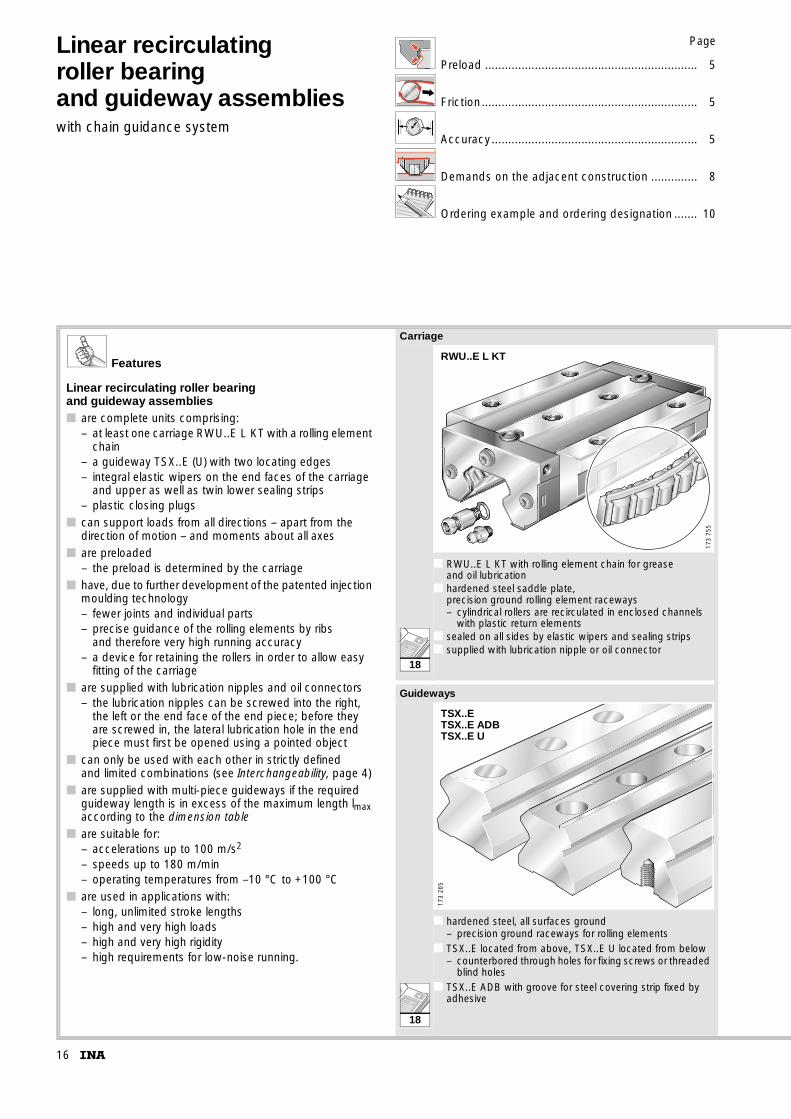
Linear recirculatingroller bearingand guideway assemblieswith chain guidance system
Page
Preload ................................................................ 5
Friction ................................................................. 5
Accuracy.............................................................. 5
Demands on the adjacent construction .............. 8
Ordering example and ordering designation ....... 10
Features
Linear recirculating roller bearingand guideway assemblies■ are complete units comprising:
– at least one carriage RWU..E L KT with a rolling element chain
– a guideway TSX..E (U) with two locating edges– integral elastic wipers on the end faces of the carriage
and upper as well as twin lower sealing strips– plastic closing plugs
■ can support loads from all directions – apart from the direction of motion – and moments about all axes
■ are preloaded– the preload is determined by the carriage
■ have, due to further development of the patented injection moulding technology– fewer joints and individual parts– precise guidance of the rolling elements by ribs
and therefore very high running accuracy– a device for retaining the rollers in order to allow easy
fitting of the carriage■ are supplied with lubrication nipples and oil connectors
– the lubrication nipples can be screwed into the right, the left or the end face of the end piece; before they are screwed in, the lateral lubrication hole in the end piece must first be opened using a pointed object
■ can only be used with each other in strictly defined and limited combinations (see Interchangeability, page 4)
■ are supplied with multi-piece guideways if the required guideway length is in excess of the maximum length lmax according to the dimension table
■ are suitable for:– accelerations up to 100 m/s2
– speeds up to 180 m/min– operating temperatures from –10 °C to +100 °C
■ are used in applications with:– long, unlimited stroke lengths– high and very high loads– high and very high rigidity– high requirements for low-noise running.
Carriage
■ RWU..E L KT with rolling element chain for grease and oil lubrication
■ hardened steel saddle plate,precision ground rolling element raceways– cylindrical rollers are recirculated in enclosed channels
with plastic return elements■ sealed on all sides by elastic wipers and sealing strips■ supplied with lubrication nipple or oil connector
Guideways
■ hardened steel, all surfaces ground– precision ground raceways for rolling elements
■ TSX..E located from above, TSX..E U located from below– counterbored through holes for fixing screws or threaded
blind holes■ TSX..E ADB with groove for steel covering strip fixed by
adhesive
RWU..E L KT
173
755
TSX..ETSX..E ADBTSX..E U
173
205
18
18
17
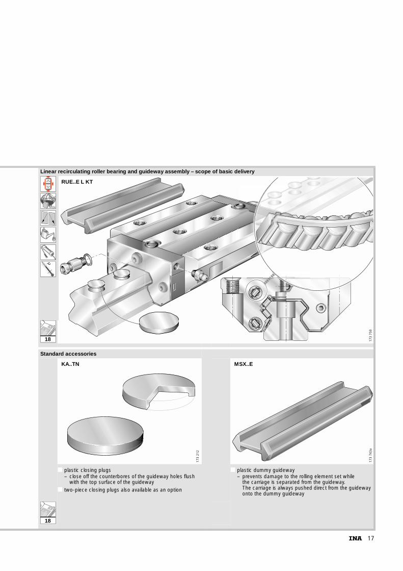
Linear recirculating roller bearing and guideway assembly – scope of basic delivery
k0M
˚C
■ ■ ■Standard accessories
■ plastic closing plugs– close off the counterbores of the guideway holes flush
with the top surface of the guideway■ two-piece closing plugs also available as an option
■ plastic dummy guideway– prevents damage to the rolling element set while
the carriage is separated from the guideway. The carriage is always pushed direct from the guideway onto the dummy guideway
RUE..E L KT
173
750
173
212
KA..TN17
3 74
3a
MSX..E
18
18

18
Linear recirculatingroller bearingand guideway assemblieswith chain guidance system
Series RUE..E L KTRUE..E HL KT
TSX..E U
Marking
Locating face
l
aRjLaL
bG1
h t7
max
172
394
1) Closing plugs KA..TN are included in the delivery.2) Maximum length of single-piece guideways;
longer guideways are supplied in several sections and are marked accordingly.Maximum single-piece guideway length of 6 m by agreement.
3) Minimum covered length for sealing the lubrication connectors.4) aL and aR are dependent on the guideway length. Calculation, page 7.5) Position of the lubrication hole in the adjacent construction.6) Maximum diameter of the lubrication hole in the adjacent construction.7) For information on fixing screws
see INA Catalogue 605, Fixing screws.
Dimension table · Dimensions in mm
Designation Carriage Guideway Dimensions Mounting dimensions
Designation Mass Designation Mass Closing plug1)
Covering strip
lmax2) H B L3) A1 JB b
m m
�kg �kg/m �0,015
RUE 35 E L KT RWU 35 E L KT 2,28 TSX 35 E (U) 5,9 KA 15 TN ADB 18 2 960 48 99,8 149 33 82 33,98
RUE 35 E HL KT RWU 35 E HL KT 2,14 TSX 35 E (U) 5,9 KA 15 TN ADB 18 2 960 55 69,8 149 18 50 33,98
RUE 45 E L KT RWU 45 E L KT 3,97 TSX 45 E (U) 9,4 KA 20 TN ADB 23 2 940 60 119,8 178,6 37,5 100 44,98
RUE 45 E HL KT RWU 45 E HL KT 3,88 TSX 45 E (U) 9,4 KA 20 TN ADB 23 2 940 70 85,8 178,6 20,5 60 44,98
Load directions
C, C0
M0xC, C0
M0z
M 0y
x
y
z
126
621
19
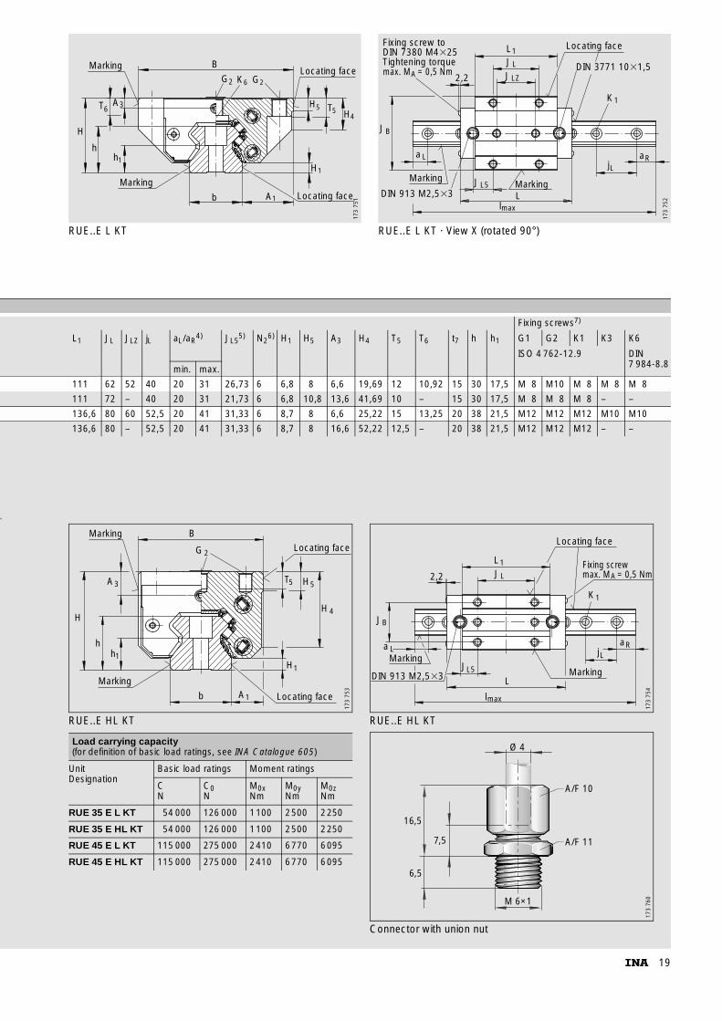
RUE..E L KT RUE..E L KT · View X (rotated 90°)
Marking
Marking
hh
T
H
6
1
3
Locating faceb A1
B
G2K6G2Locating face
H
H5 T5 H4
1
A
173
751
Marking
max
Marking
Locating face
2,2
L1JL
JLZ
JB
a L
JL5
Ll
K1
jLaR
DIN 913 M2,5�3
Fixing screw toDIN 7380 M4�25Tightening torque DIN 3771 10�1,5max. M = 0,5 NmA
173
752
az
Fixing screws7)
L1 JL JLZ jL aL/aR4) JL5
5) N26) H1 H5 A3 H4 T5 T6 t7 h h1 G1 G2 K1 K3 K6
ISO 4 762-12.9 DIN 7 984-8.8min. max.
111 62 52 40 20 31 26,73 6 6,8 8 6,6 19,69 12 10,92 15 30 17,5 M 8 M10 M 8 M 8 M 8
111 72 – 40 20 31 21,73 6 6,8 10,8 13,6 41,69 10 – 15 30 17,5 M 8 M 8 M 8 – –
136,6 80 60 52,5 20 41 31,33 6 8,7 8 6,6 25,22 15 13,25 20 38 21,5 M12 M12 M12 M10 M10
136,6 80 – 52,5 20 41 31,33 6 8,7 8 16,6 52,22 12,5 – 20 38 21,5 M12 M12 M12 – –
RUE..E HL KT RUE..E HL KT
Connector with union nut
Load carrying capacity(for definition of basic load ratings, see INA Catalogue 605)
UnitDesignation
Basic load ratings Moment ratings
CN
C0N
M0xNm
M0yNm
M0zNm
RUE 35 E L KT 54 000 126 000 1100 2500 2250
RUE 35 E HL KT 54 000 126 000 1100 2500 2250
RUE 45 E L KT 115 000 275 000 2410 6770 6095
RUE 45 E HL KT 115 000 275 000 2410 6770 6095
b A1 Locating face
H1
Locating face
T H5 5
H 4
B
G 2
A3
H
h
Marking
Marking
h1
173
753
L1
K1
aRjL
L
l
JL5
JB
JL
DIN 913 M2,5�3
2,2
Marking
Locating face
Fixing screwmax. M = 0,5 NmA
max
a LMarking
173
754
16,5
6,5
7,5
M 6×1
Ø 4
A/F 10
A/F 11
173
760
INA-Schaeffler KGLinear Technology Division66406 Homburg (Saar) · GermanyInternet www.ina.comE-Mail [email protected] Germany:Telephone 0180 / 5 00 38 72Fax 0180 / 5 00 38 73From other countries:Telephone +49 / 68 41/ 7 01-0Fax +49 / 68 41/ 7 01-6 25 S
ach-
Nr.
017-
411-
386/
MA
I 92
GB
-D 0
4032
· P
rinte
d in
Ger
man
y