Embed Size (px)
Citation preview
Journal of Physics Conference Series
OPEN ACCESS
Linear array of photodiodes to track a humanspeaker for video recordingTo cite this article D DeTone et al 2012 J Phys Conf Ser 396 062005
View the article online for updates and enhancements
You may also likeQuantum phase transitions in the Kondo-necklace model perturbative continuousunitary transformation approachS Hemmatiyan M Rahimi Movassagh NGhassemi et al
-
Ground-state phases and spin textures ofspinndashorbit-coupled dipolar BosendashEinsteincondensates in a rotating toroidal trapQing-Bo Wang Hui Yang et al
-
Modulation instability of structured-lightbeams in negative-index metamaterialsSalih Z Silahli Wiktor Walasik and NataliaM Litchinitser
-
This content was downloaded from IP address 79147191186 on 13122021 at 1304
Linear array of photodiodes to track a human speaker for video recording
D DeTone H Neal R Lougheed Department of Physics University of Michigan Ann Arbor MI 48109 USA
ddetoneumichedu hanealumichedu rlougheeumichedu Abstract Communication and collaboration using stored digital media has garnered more interest by many areas of business government and education in recent years This is due primarily to improvements in the quality of cameras and speed of computers An advantage of digital media is that it can serve as an effective alternative when physical interaction is not possible Video recordings that allow for viewers to discern a presenterrsquos facial features lips and hand motions are more effective than videos that do not To attain this one must maintain a video capture in which the speaker occupies a significant portion of the captured pixels However camera operators are costly and often do an imperfect job of tracking presenters in unrehearsed situations This creates motivation for a robust automated system that directs a video camera to follow a presenter as he or she walks anywhere in the front of a lecture hall or large conference room Such a system is presented
The system consists of a commercial off-the-shelf pantiltzoom (PTZ) color video camera a necklace of infrared LEDs and a linear photodiode array detector Electronic output from the photodiode array is processed to generate the location of the LED necklace which is worn by a human speaker The computer controls the video camera movements to record video of the speaker The speakerrsquos vertical position and depth are assumed to remain relatively constantndashthe video camera is sent only panning (horizontal) movement commands The LED necklace is flashed at 70Hz at a 50 duty cycle to provide noise-filtering capability The benefit to using a photodiode array versus a standard video camera is its higher frame rate (4kHz vs 60Hz) The higher frame rate allows for the filtering of infrared noise such as sunlight and indoor lightingndasha capability absent from other tracking technologies The system has been tested in a large lecture hall and is shown to be effective
1 Introduction The ATLAS Experiment one of the largest experiments based at CERN is being built by a collaboration of almost 3000 physicists who are based at institutions spread across the globe It is one of the largest collaborative efforts ever attempted in the physical sciences [1] The success of the experiment depends upon successful long-distance collaboration and the ATLAS Collaboratory Project [2] was created to address the needs of ATLAS with respect to collaborative tools For the first few years the activities of our group were limited to recording single lectures tutorials and small conferences There were clearly situations in which large-scale recording is needed for example at the national meetings of large professional societies such as the American Physical Society (APS) [3] where many parallel talks take place and where many members are interested but unable to attend In
International Conference on Computing in High Energy and Nuclear Physics 2012 (CHEP2012) IOP PublishingJournal of Physics Conference Series 396 (2012) 062005 doi1010881742-65963966062005
Published under licence by IOP Publishing Ltd 1
addition to large national meetings universities are also exploring the usage of large-scale recorded video and audio of classroom lectures for use as an educational aide The advantages of having recorded media for students are apparent the videos help students with course material review prior to exams support students that are unable to attend lecture and allow for unlimited repetition to aid in comprehension especially for students of which English is not their first language [4] The ATLAS Collaboratory Project group along with the APS received a grant in 2003 from the National Science Digital Library division of the NSF making possible an increased focus on the prompt compression and posting of web lectures Our team assembled the appropriate hardware and developed software to gain substantial ground in this pursuit With the successful completion of the MScribe [5] pilot project at the University of Michigan which brought lecture recording into the classroom it has been demonstrated that large-scale automated lecture recording is feasible and imminent
One feature that is particularly important for performing automated lecture capture is body framing A video recording that uses body framing ndash a characteristic of a video recording in which one can clearly discern the presenterrsquos facial features lips and hand motions through an appropriate zoom ndash renders the recorded media more effective than a video recording that only captures a wide-angle view of the entire stage This is apparent by comparing Figure 1a with Figure 1b Implementing a system
Fig 1a ndash An image of a speaker recording system without body framing
Fig 1b ndash An image of a speaker recording system with body framing
with body framing can be done by a camera technician who pans and zooms a video camera to keep the video framed close to the presenterrsquos body However camera operators are costly and often do an imperfect job of tracking presenters in unrehearsed situations This spawns the need for robotic tracking to provide reliable high-quality smooth video of the presenter As described by the MScribe pilot project a tracking system used for large-scale video collaboration must meet the following criteria
bull Portable bull Accurate bull Robust bull Affordable bull Operate without expert intervention bull Require minimal setup or calibration In 2005-2007 a robotic tracking system [6] was developed by MScribe a part of the ATLAS
Collaboratory Project to meet the aforementioned requirements This original system uses two identical models of off-the-shelf pantiltzoom (PTZ) video cameras and a special necklace that is worn by the speaker comprised of continuously illuminated infrared (IR) LEDs One camera is equipped with appropriate IR filters so that it detects only the LEDs and follows the necklace around the room Based on this position information the second camera is pointed appropriately at the instructor to provide color video footage
International Conference on Computing in High Energy and Nuclear Physics 2012 (CHEP2012) IOP PublishingJournal of Physics Conference Series 396 (2012) 062005 doi1010881742-65963966062005
2
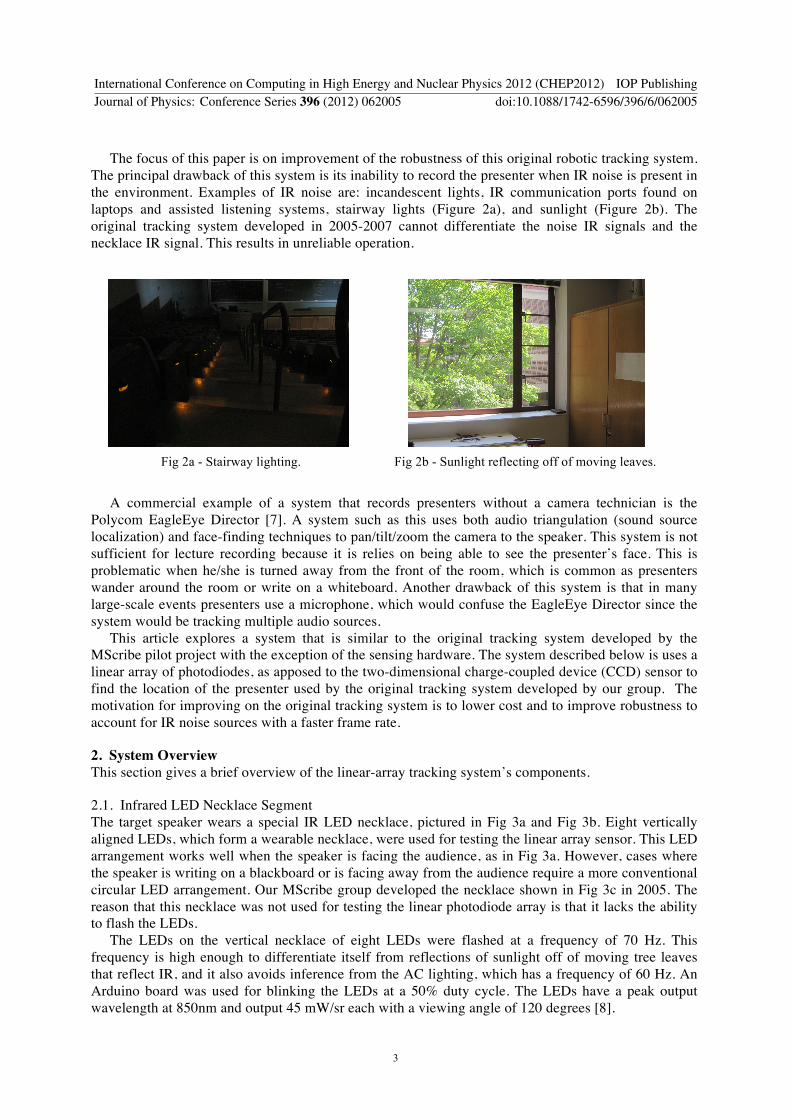
The focus of this paper is on improvement of the robustness of this original robotic tracking system The principal drawback of this system is its inability to record the presenter when IR noise is present in the environment Examples of IR noise are incandescent lights IR communication ports found on laptops and assisted listening systems stairway lights (Figure 2a) and sunlight (Figure 2b) The original tracking system developed in 2005-2007 cannot differentiate the noise IR signals and the necklace IR signal This results in unreliable operation
Fig 2a - Stairway lighting
Fig 2b - Sunlight reflecting off of moving leaves
A commercial example of a system that records presenters without a camera technician is the Polycom EagleEye Director [7] A system such as this uses both audio triangulation (sound source localization) and face-finding techniques to pantiltzoom the camera to the speaker This system is not sufficient for lecture recording because it is relies on being able to see the presenterrsquos face This is problematic when heshe is turned away from the front of the room which is common as presenters wander around the room or write on a whiteboard Another drawback of this system is that in many large-scale events presenters use a microphone which would confuse the EagleEye Director since the system would be tracking multiple audio sources
This article explores a system that is similar to the original tracking system developed by the MScribe pilot project with the exception of the sensing hardware The system described below is uses a linear array of photodiodes as apposed to the two-dimensional charge-coupled device (CCD) sensor to find the location of the presenter used by the original tracking system developed by our group The motivation for improving on the original tracking system is to lower cost and to improve robustness to account for IR noise sources with a faster frame rate
2 System Overview This section gives a brief overview of the linear-array tracking systemrsquos components
21 Infrared LED Necklace Segment The target speaker wears a special IR LED necklace pictured in Fig 3a and Fig 3b Eight vertically aligned LEDs which form a wearable necklace were used for testing the linear array sensor This LED arrangement works well when the speaker is facing the audience as in Fig 3a However cases where the speaker is writing on a blackboard or is facing away from the audience require a more conventional circular LED arrangement Our MScribe group developed the necklace shown in Fig 3c in 2005 The reason that this necklace was not used for testing the linear photodiode array is that it lacks the ability to flash the LEDs
The LEDs on the vertical necklace of eight LEDs were flashed at a frequency of 70 Hz This frequency is high enough to differentiate itself from reflections of sunlight off of moving tree leaves that reflect IR and it also avoids inference from the AC lighting which has a frequency of 60 Hz An Arduino board was used for blinking the LEDs at a 50 duty cycle The LEDs have a peak output wavelength at 850nm and output 45 mWsr each with a viewing angle of 120 degrees [8]
International Conference on Computing in High Energy and Nuclear Physics 2012 (CHEP2012) IOP PublishingJournal of Physics Conference Series 396 (2012) 062005 doi1010881742-65963966062005
3
Fig 3a A speaker wearing
the prototype necklace
Fig 3b The prototype flashing necklace Fig 3c An ideal circular necklace can be viewed when
the speaker is facing away from the camera
22 Linear photodiode array The linear array of photodiodes consists of 128 horizontal photodiodes and has physical dimensions of 5 cm x 25 cm (Figure 4b) The IR light from the LEDs strikes the photodiodes via a converging lens (Figure 4a) The linear array sensor used was the Hamamatsu S8865-128 [9] in combination with a Hamamatsu C9118 driver circuit and can be seen in Figure 4a The linear array outputs an analog signal representing the amount of IR light falling on each photodiode for all 128 photodiodes at a maximum frame rate of 4kHz It is essentially a one-dimensional video output The frame rate used for testing was 448Hz The cost of this particular array and driver circuit is about $750 The individual photosensitive diodes on the linear array board have a width of 03 mm and height of 06 mm
Fig 4a ndash Lens and array (bottom) PTZ camera (top)
Fig 4b ndash Close up of linear array
23 Interface A National Instruments USB-5132 high-speed digitizer was used to interface the linear array driver circuit and the computer It captured three signals the analog video signal from the photodiodes the signal to trigger a new video frame scan and the signal that triggers the start of each of the 128 pixels
24 Software National Instruments Labview software was used to process the data from the digitizer Microsoft Visual Studio was used to create the commands to the PTZ camera More detail on the band-pass filter is given is Section 4
International Conference on Computing in High Energy and Nuclear Physics 2012 (CHEP2012) IOP PublishingJournal of Physics Conference Series 396 (2012) 062005 doi1010881742-65963966062005
4
25 Camera The camera used for recording the color video recording was a Sony EVI-HD1 PTZ camera A computer processes the signal from the linear array performs noise-filtering computations and instructs the camera where to pan via RS-232 VISCA commands VISCA is the camera control protocol used by this Sony camera
3 Single LED Characteristics
31 Accuracy As the presenter wearing the LED necklace moves across the stage different diodes within the linear array output a high signal which is sent to the computer for processing An important measureable characteristic of a tracking system such as this is the amount of movement that is required for a new position to be detected by the linear array This is characteristic is considered the systemrsquos accuracy
A single LED was used to determine the accuracy of the linear array The LED was affixed to a train set to provide controlled and measurable motion as pictured in Figure 5a the IR LED is circled in the photo The basic concept of this test is illustrated in Figure 5b The red line uses the pinhole approximation for a converging lens to represent how the red IR light passes through the lens and onto the photodiode elements As the IR necklace moves across the stage area the IR light will strike new photodiode elements in the array
Fig 5a ndash A single LED used for the accuracy test
Fig 5b ndash Optical principal of linear array sensor
The results of this test are shown below in Figure 6 which shows a composite of multiple locations of the LED as it is moved across the field of view Each row of diamonds represents a photodiode element that detected light exceeding a threshold The graph exhibits a near linear relationship between the actual and calculated locations of the IR LEDs A perfect system would exhibit a straight line as it would correctly calculate each change in location of the LED In the worst-case four different locations of the target correspond to the same calculated location Each location of the target is separated by frac12 inch thus the system accuracy in this experiment (at 22 feet) is +- two inches
International Conference on Computing in High Energy and Nuclear Physics 2012 (CHEP2012) IOP PublishingJournal of Physics Conference Series 396 (2012) 062005 doi1010881742-65963966062005
5
32 Allowable Vertical Movement In addition to horizontal accuracy the vertical displacement is another important characteristic to measure for a speaker tracking system The principal drawback of this system is its inability to determine the vertical position of the IR LEDs A single LED was tested to have an allowable vertical movement range of 35 inches at a distance of 22 feet from the linear array sensor In most cases it is assumed that the height of the speaker will not change and the system performs well However rooms with elevated stages angled stages or steep stadium seating present difficulty when the speaker travels the depth of the stage
4 Noise IR Filtering A presenter tracking system that tracks an IR necklace must be able to ignore IR noise signals to be considered a robust system [5] To test this function the linear array system was set up in a large lecture hall shown in Fig 7a The array was 44 feet from the speaker pictured at center stage Three noise sourcesndashan overhead projector and two halogen lampsndashwere added at a similar height as the speaker to replicate equipment typically found in a lecture hall
Fig 7a ndash The speaker is shown in the large lecture hall with three sources of IR light that can confuse an IR tracker
Fig 6 ndash A plot of actual vs calculated locations for the single LED target
Worst Case plusmn 2 in
International Conference on Computing in High Energy and Nuclear Physics 2012 (CHEP2012) IOP PublishingJournal of Physics Conference Series 396 (2012) 062005 doi1010881742-65963966062005
6
Fig 7b is a wide-angle IR image of the entire lecture stage The objects that emitted IR light are labeled Andashoverhead projector Bndashflashing desklamp (4Hz) CndashLED necklace (70Hz) DndashDC desklamp A narrow rectangle is added to Fig 7b to represent the limited vertical viewing capability of the linear array sensor system Only IR objects that fall in that vertical range are sensed by the linear array ndash if the speaker were to change hisher height due to stepping on the stairs into the audience hisher position would be lost
The method used to filter the non-necklace IR signals in this system is a digital band-pass filter implemented in Labview The software behind the linear array tracking system operates as follows the output voltages from each of the 128 photodiodes is recorded for 4-5 cycles of the LEDsrsquo flashing and then passed through the band-pass filter corresponding to 70 Hz Then a peak detector function calculates a position value to the peak of the surviving voltage peak In the case of the test ran in Fig 8 this surviving peak on the bottom graph is the LED necklace This value is written to a txt file Microsoft Visual Studio then runs C code to read from this txt file and to send VISCA panning commands to the color camera to follow the speaker to this new location
A B C D
Fig 7b ndash An IR image of the stage shown in Fig 7a The horizontal grey bar represents the limited vertical viewing angle of the linear array sensor
A B C D
C
Fig 8 ndash Graphical representation of the signal from the linear array photodiode sensor The x-axis is diode number [0-127] and the y-axis is voltage (volts) The top
plot is before the band-pass filter the bottom plot is after the filter
International Conference on Computing in High Energy and Nuclear Physics 2012 (CHEP2012) IOP PublishingJournal of Physics Conference Series 396 (2012) 062005 doi1010881742-65963966062005
7
The graph in Fig 8 plots diode number [0-127] (x-axis) versus voltage (y-axis) The top plot in Fig 8 is unfiltered and consists of the same IR sources from Fig 7b The IR sources are reversed left to right The bottom plot is filtered through the band pass filter and shows only the 70Hz necklace
A demonstration video of the linear array tracking and recording system is available on our research webpage lsquohttpatlascollabumichedursquo under Projects agrave Robotic Tracking This demonstration was done in the same lecture hall seen in Fig 7a and shows that the system does a good job of following the speaker as he walks back and forth along the stage
5 Conclusion An IR-based tracking system is presented to meet the growing need for large-scale automatic video recording that frames the speakerrsquos body in video capture The first system created by the ATLAS Collaboratory project in 2005-2007 did a good job of accomplishing automated lecture recording in an environment with a single IR light source However the system failed to work well in the presence of other IR sources (incandescent lights sunlight) which commonly exist in lecture rooms This first system created by our group used a CCD sensor To add noise-filtering capability the sensor was simplified to have 128 horizontal linearly arranged diodes This is a large reduction from the hundreds of thousands to millions of effective pixels found in CCD sensors of todayrsquos standard and HD video cameras This reduction in the number of pixels on the sensor means less data from the sensing hardware must be processed thus a faster frame update rate can be achieved
The main advantage of the linear array system is its processing speed In an application such as human speaker tracking having an IR-based detection system with a fast processing speed allows for effective noise filtering via a software-based band-pass filter which is necessary to reject other sources of IR light Another benefit to using the linear array for speaker tracking is its relatively low cost compared to using a PTZ camera for tracking
Fig 9 ndash Detection range and processing speed show an inverse relationship
The main limitation of this system is its inability to capture vertical movements performed by the speaker Rooms with elevated stages angled stages or steep stadium seating present difficulty to a system that does not account for vertical movements and adjust the tilt of the camera accordingly Fig 9 suggests an optimal medium between a linear array system and a video camera with a full 2-D CCD sensor The reason that a full 2-D CCD sensor is not used with this technique is that it is too processing intensive (128 vs gt100000 pixel values) and the frame-scanning rate is too slow A more robust and optimal system would stack 3-10 linear arrays on top of one another in the film plane to detect change in vertical positioning of the speaker and would possess much fewer pixel values than a CCD sensor
Processing Speed ndash FAST Detection Range ndash SMALL
Processing Speed ndash SLOW Detection Range ndash LARGE
Linear Array System
Standard 2-D CCD Camera
Optimal Tracking System
International Conference on Computing in High Energy and Nuclear Physics 2012 (CHEP2012) IOP PublishingJournal of Physics Conference Series 396 (2012) 062005 doi1010881742-65963966062005
8
References [1] The ATLAS Experiment httpwwwatlasch [2] The ATLAS Collaboratory Project httpatlascollabumichedu [3] The American Physical Society httpapsorg [4] Odhabi H Nicks-McCaleb L (2011) Video recording lectures student and professor
perspectives British Journal of Educational Technology Vol 42 No2 pp327-336 [5] MScribe Pilot Project httpatlascollabumichedumscribehtml [6] ATLAS Collaboratory Project Robotics Tracking Video
httpatlascollabumichedutrackingentire-demo-5amov [7] Polycom EagleEye Director
httpwwwpolycomcomproductstelepresence_videoaccessorieshdx_accessorieseagleeye_directorhtml
[8] Dominant Semiconductor SPNova InfraRed LED httpwwwdominant-semicomindexphpp=contents-itemampid=90 [9] Hamamatsu S8865-128 httpsaleshamamatsucomenproductssolid-state-divisionsi-photodiode-seriessi-photodiode-arraypart-s8865-128php
International Conference on Computing in High Energy and Nuclear Physics 2012 (CHEP2012) IOP PublishingJournal of Physics Conference Series 396 (2012) 062005 doi1010881742-65963966062005
9
Linear array of photodiodes to track a human speaker for video recording
D DeTone H Neal R Lougheed Department of Physics University of Michigan Ann Arbor MI 48109 USA
ddetoneumichedu hanealumichedu rlougheeumichedu Abstract Communication and collaboration using stored digital media has garnered more interest by many areas of business government and education in recent years This is due primarily to improvements in the quality of cameras and speed of computers An advantage of digital media is that it can serve as an effective alternative when physical interaction is not possible Video recordings that allow for viewers to discern a presenterrsquos facial features lips and hand motions are more effective than videos that do not To attain this one must maintain a video capture in which the speaker occupies a significant portion of the captured pixels However camera operators are costly and often do an imperfect job of tracking presenters in unrehearsed situations This creates motivation for a robust automated system that directs a video camera to follow a presenter as he or she walks anywhere in the front of a lecture hall or large conference room Such a system is presented
The system consists of a commercial off-the-shelf pantiltzoom (PTZ) color video camera a necklace of infrared LEDs and a linear photodiode array detector Electronic output from the photodiode array is processed to generate the location of the LED necklace which is worn by a human speaker The computer controls the video camera movements to record video of the speaker The speakerrsquos vertical position and depth are assumed to remain relatively constantndashthe video camera is sent only panning (horizontal) movement commands The LED necklace is flashed at 70Hz at a 50 duty cycle to provide noise-filtering capability The benefit to using a photodiode array versus a standard video camera is its higher frame rate (4kHz vs 60Hz) The higher frame rate allows for the filtering of infrared noise such as sunlight and indoor lightingndasha capability absent from other tracking technologies The system has been tested in a large lecture hall and is shown to be effective
1 Introduction The ATLAS Experiment one of the largest experiments based at CERN is being built by a collaboration of almost 3000 physicists who are based at institutions spread across the globe It is one of the largest collaborative efforts ever attempted in the physical sciences [1] The success of the experiment depends upon successful long-distance collaboration and the ATLAS Collaboratory Project [2] was created to address the needs of ATLAS with respect to collaborative tools For the first few years the activities of our group were limited to recording single lectures tutorials and small conferences There were clearly situations in which large-scale recording is needed for example at the national meetings of large professional societies such as the American Physical Society (APS) [3] where many parallel talks take place and where many members are interested but unable to attend In
International Conference on Computing in High Energy and Nuclear Physics 2012 (CHEP2012) IOP PublishingJournal of Physics Conference Series 396 (2012) 062005 doi1010881742-65963966062005
Published under licence by IOP Publishing Ltd 1
addition to large national meetings universities are also exploring the usage of large-scale recorded video and audio of classroom lectures for use as an educational aide The advantages of having recorded media for students are apparent the videos help students with course material review prior to exams support students that are unable to attend lecture and allow for unlimited repetition to aid in comprehension especially for students of which English is not their first language [4] The ATLAS Collaboratory Project group along with the APS received a grant in 2003 from the National Science Digital Library division of the NSF making possible an increased focus on the prompt compression and posting of web lectures Our team assembled the appropriate hardware and developed software to gain substantial ground in this pursuit With the successful completion of the MScribe [5] pilot project at the University of Michigan which brought lecture recording into the classroom it has been demonstrated that large-scale automated lecture recording is feasible and imminent
One feature that is particularly important for performing automated lecture capture is body framing A video recording that uses body framing ndash a characteristic of a video recording in which one can clearly discern the presenterrsquos facial features lips and hand motions through an appropriate zoom ndash renders the recorded media more effective than a video recording that only captures a wide-angle view of the entire stage This is apparent by comparing Figure 1a with Figure 1b Implementing a system
Fig 1a ndash An image of a speaker recording system without body framing
Fig 1b ndash An image of a speaker recording system with body framing
with body framing can be done by a camera technician who pans and zooms a video camera to keep the video framed close to the presenterrsquos body However camera operators are costly and often do an imperfect job of tracking presenters in unrehearsed situations This spawns the need for robotic tracking to provide reliable high-quality smooth video of the presenter As described by the MScribe pilot project a tracking system used for large-scale video collaboration must meet the following criteria
bull Portable bull Accurate bull Robust bull Affordable bull Operate without expert intervention bull Require minimal setup or calibration In 2005-2007 a robotic tracking system [6] was developed by MScribe a part of the ATLAS
Collaboratory Project to meet the aforementioned requirements This original system uses two identical models of off-the-shelf pantiltzoom (PTZ) video cameras and a special necklace that is worn by the speaker comprised of continuously illuminated infrared (IR) LEDs One camera is equipped with appropriate IR filters so that it detects only the LEDs and follows the necklace around the room Based on this position information the second camera is pointed appropriately at the instructor to provide color video footage
International Conference on Computing in High Energy and Nuclear Physics 2012 (CHEP2012) IOP PublishingJournal of Physics Conference Series 396 (2012) 062005 doi1010881742-65963966062005
2
The focus of this paper is on improvement of the robustness of this original robotic tracking system The principal drawback of this system is its inability to record the presenter when IR noise is present in the environment Examples of IR noise are incandescent lights IR communication ports found on laptops and assisted listening systems stairway lights (Figure 2a) and sunlight (Figure 2b) The original tracking system developed in 2005-2007 cannot differentiate the noise IR signals and the necklace IR signal This results in unreliable operation
Fig 2a - Stairway lighting
Fig 2b - Sunlight reflecting off of moving leaves
A commercial example of a system that records presenters without a camera technician is the Polycom EagleEye Director [7] A system such as this uses both audio triangulation (sound source localization) and face-finding techniques to pantiltzoom the camera to the speaker This system is not sufficient for lecture recording because it is relies on being able to see the presenterrsquos face This is problematic when heshe is turned away from the front of the room which is common as presenters wander around the room or write on a whiteboard Another drawback of this system is that in many large-scale events presenters use a microphone which would confuse the EagleEye Director since the system would be tracking multiple audio sources
This article explores a system that is similar to the original tracking system developed by the MScribe pilot project with the exception of the sensing hardware The system described below is uses a linear array of photodiodes as apposed to the two-dimensional charge-coupled device (CCD) sensor to find the location of the presenter used by the original tracking system developed by our group The motivation for improving on the original tracking system is to lower cost and to improve robustness to account for IR noise sources with a faster frame rate
2 System Overview This section gives a brief overview of the linear-array tracking systemrsquos components
21 Infrared LED Necklace Segment The target speaker wears a special IR LED necklace pictured in Fig 3a and Fig 3b Eight vertically aligned LEDs which form a wearable necklace were used for testing the linear array sensor This LED arrangement works well when the speaker is facing the audience as in Fig 3a However cases where the speaker is writing on a blackboard or is facing away from the audience require a more conventional circular LED arrangement Our MScribe group developed the necklace shown in Fig 3c in 2005 The reason that this necklace was not used for testing the linear photodiode array is that it lacks the ability to flash the LEDs
The LEDs on the vertical necklace of eight LEDs were flashed at a frequency of 70 Hz This frequency is high enough to differentiate itself from reflections of sunlight off of moving tree leaves that reflect IR and it also avoids inference from the AC lighting which has a frequency of 60 Hz An Arduino board was used for blinking the LEDs at a 50 duty cycle The LEDs have a peak output wavelength at 850nm and output 45 mWsr each with a viewing angle of 120 degrees [8]
International Conference on Computing in High Energy and Nuclear Physics 2012 (CHEP2012) IOP PublishingJournal of Physics Conference Series 396 (2012) 062005 doi1010881742-65963966062005
3
Fig 3a A speaker wearing
the prototype necklace
Fig 3b The prototype flashing necklace Fig 3c An ideal circular necklace can be viewed when
the speaker is facing away from the camera
22 Linear photodiode array The linear array of photodiodes consists of 128 horizontal photodiodes and has physical dimensions of 5 cm x 25 cm (Figure 4b) The IR light from the LEDs strikes the photodiodes via a converging lens (Figure 4a) The linear array sensor used was the Hamamatsu S8865-128 [9] in combination with a Hamamatsu C9118 driver circuit and can be seen in Figure 4a The linear array outputs an analog signal representing the amount of IR light falling on each photodiode for all 128 photodiodes at a maximum frame rate of 4kHz It is essentially a one-dimensional video output The frame rate used for testing was 448Hz The cost of this particular array and driver circuit is about $750 The individual photosensitive diodes on the linear array board have a width of 03 mm and height of 06 mm
Fig 4a ndash Lens and array (bottom) PTZ camera (top)
Fig 4b ndash Close up of linear array
23 Interface A National Instruments USB-5132 high-speed digitizer was used to interface the linear array driver circuit and the computer It captured three signals the analog video signal from the photodiodes the signal to trigger a new video frame scan and the signal that triggers the start of each of the 128 pixels
24 Software National Instruments Labview software was used to process the data from the digitizer Microsoft Visual Studio was used to create the commands to the PTZ camera More detail on the band-pass filter is given is Section 4
International Conference on Computing in High Energy and Nuclear Physics 2012 (CHEP2012) IOP PublishingJournal of Physics Conference Series 396 (2012) 062005 doi1010881742-65963966062005
4
25 Camera The camera used for recording the color video recording was a Sony EVI-HD1 PTZ camera A computer processes the signal from the linear array performs noise-filtering computations and instructs the camera where to pan via RS-232 VISCA commands VISCA is the camera control protocol used by this Sony camera
3 Single LED Characteristics
31 Accuracy As the presenter wearing the LED necklace moves across the stage different diodes within the linear array output a high signal which is sent to the computer for processing An important measureable characteristic of a tracking system such as this is the amount of movement that is required for a new position to be detected by the linear array This is characteristic is considered the systemrsquos accuracy
A single LED was used to determine the accuracy of the linear array The LED was affixed to a train set to provide controlled and measurable motion as pictured in Figure 5a the IR LED is circled in the photo The basic concept of this test is illustrated in Figure 5b The red line uses the pinhole approximation for a converging lens to represent how the red IR light passes through the lens and onto the photodiode elements As the IR necklace moves across the stage area the IR light will strike new photodiode elements in the array
Fig 5a ndash A single LED used for the accuracy test
Fig 5b ndash Optical principal of linear array sensor
The results of this test are shown below in Figure 6 which shows a composite of multiple locations of the LED as it is moved across the field of view Each row of diamonds represents a photodiode element that detected light exceeding a threshold The graph exhibits a near linear relationship between the actual and calculated locations of the IR LEDs A perfect system would exhibit a straight line as it would correctly calculate each change in location of the LED In the worst-case four different locations of the target correspond to the same calculated location Each location of the target is separated by frac12 inch thus the system accuracy in this experiment (at 22 feet) is +- two inches
International Conference on Computing in High Energy and Nuclear Physics 2012 (CHEP2012) IOP PublishingJournal of Physics Conference Series 396 (2012) 062005 doi1010881742-65963966062005
5
32 Allowable Vertical Movement In addition to horizontal accuracy the vertical displacement is another important characteristic to measure for a speaker tracking system The principal drawback of this system is its inability to determine the vertical position of the IR LEDs A single LED was tested to have an allowable vertical movement range of 35 inches at a distance of 22 feet from the linear array sensor In most cases it is assumed that the height of the speaker will not change and the system performs well However rooms with elevated stages angled stages or steep stadium seating present difficulty when the speaker travels the depth of the stage
4 Noise IR Filtering A presenter tracking system that tracks an IR necklace must be able to ignore IR noise signals to be considered a robust system [5] To test this function the linear array system was set up in a large lecture hall shown in Fig 7a The array was 44 feet from the speaker pictured at center stage Three noise sourcesndashan overhead projector and two halogen lampsndashwere added at a similar height as the speaker to replicate equipment typically found in a lecture hall
Fig 7a ndash The speaker is shown in the large lecture hall with three sources of IR light that can confuse an IR tracker
Fig 6 ndash A plot of actual vs calculated locations for the single LED target
Worst Case plusmn 2 in
International Conference on Computing in High Energy and Nuclear Physics 2012 (CHEP2012) IOP PublishingJournal of Physics Conference Series 396 (2012) 062005 doi1010881742-65963966062005
6
Fig 7b is a wide-angle IR image of the entire lecture stage The objects that emitted IR light are labeled Andashoverhead projector Bndashflashing desklamp (4Hz) CndashLED necklace (70Hz) DndashDC desklamp A narrow rectangle is added to Fig 7b to represent the limited vertical viewing capability of the linear array sensor system Only IR objects that fall in that vertical range are sensed by the linear array ndash if the speaker were to change hisher height due to stepping on the stairs into the audience hisher position would be lost
The method used to filter the non-necklace IR signals in this system is a digital band-pass filter implemented in Labview The software behind the linear array tracking system operates as follows the output voltages from each of the 128 photodiodes is recorded for 4-5 cycles of the LEDsrsquo flashing and then passed through the band-pass filter corresponding to 70 Hz Then a peak detector function calculates a position value to the peak of the surviving voltage peak In the case of the test ran in Fig 8 this surviving peak on the bottom graph is the LED necklace This value is written to a txt file Microsoft Visual Studio then runs C code to read from this txt file and to send VISCA panning commands to the color camera to follow the speaker to this new location
A B C D
Fig 7b ndash An IR image of the stage shown in Fig 7a The horizontal grey bar represents the limited vertical viewing angle of the linear array sensor
A B C D
C
Fig 8 ndash Graphical representation of the signal from the linear array photodiode sensor The x-axis is diode number [0-127] and the y-axis is voltage (volts) The top
plot is before the band-pass filter the bottom plot is after the filter
International Conference on Computing in High Energy and Nuclear Physics 2012 (CHEP2012) IOP PublishingJournal of Physics Conference Series 396 (2012) 062005 doi1010881742-65963966062005
7
The graph in Fig 8 plots diode number [0-127] (x-axis) versus voltage (y-axis) The top plot in Fig 8 is unfiltered and consists of the same IR sources from Fig 7b The IR sources are reversed left to right The bottom plot is filtered through the band pass filter and shows only the 70Hz necklace
A demonstration video of the linear array tracking and recording system is available on our research webpage lsquohttpatlascollabumichedursquo under Projects agrave Robotic Tracking This demonstration was done in the same lecture hall seen in Fig 7a and shows that the system does a good job of following the speaker as he walks back and forth along the stage
5 Conclusion An IR-based tracking system is presented to meet the growing need for large-scale automatic video recording that frames the speakerrsquos body in video capture The first system created by the ATLAS Collaboratory project in 2005-2007 did a good job of accomplishing automated lecture recording in an environment with a single IR light source However the system failed to work well in the presence of other IR sources (incandescent lights sunlight) which commonly exist in lecture rooms This first system created by our group used a CCD sensor To add noise-filtering capability the sensor was simplified to have 128 horizontal linearly arranged diodes This is a large reduction from the hundreds of thousands to millions of effective pixels found in CCD sensors of todayrsquos standard and HD video cameras This reduction in the number of pixels on the sensor means less data from the sensing hardware must be processed thus a faster frame update rate can be achieved
The main advantage of the linear array system is its processing speed In an application such as human speaker tracking having an IR-based detection system with a fast processing speed allows for effective noise filtering via a software-based band-pass filter which is necessary to reject other sources of IR light Another benefit to using the linear array for speaker tracking is its relatively low cost compared to using a PTZ camera for tracking
Fig 9 ndash Detection range and processing speed show an inverse relationship
The main limitation of this system is its inability to capture vertical movements performed by the speaker Rooms with elevated stages angled stages or steep stadium seating present difficulty to a system that does not account for vertical movements and adjust the tilt of the camera accordingly Fig 9 suggests an optimal medium between a linear array system and a video camera with a full 2-D CCD sensor The reason that a full 2-D CCD sensor is not used with this technique is that it is too processing intensive (128 vs gt100000 pixel values) and the frame-scanning rate is too slow A more robust and optimal system would stack 3-10 linear arrays on top of one another in the film plane to detect change in vertical positioning of the speaker and would possess much fewer pixel values than a CCD sensor
Processing Speed ndash FAST Detection Range ndash SMALL
Processing Speed ndash SLOW Detection Range ndash LARGE
Linear Array System
Standard 2-D CCD Camera
Optimal Tracking System
International Conference on Computing in High Energy and Nuclear Physics 2012 (CHEP2012) IOP PublishingJournal of Physics Conference Series 396 (2012) 062005 doi1010881742-65963966062005
8
References [1] The ATLAS Experiment httpwwwatlasch [2] The ATLAS Collaboratory Project httpatlascollabumichedu [3] The American Physical Society httpapsorg [4] Odhabi H Nicks-McCaleb L (2011) Video recording lectures student and professor
perspectives British Journal of Educational Technology Vol 42 No2 pp327-336 [5] MScribe Pilot Project httpatlascollabumichedumscribehtml [6] ATLAS Collaboratory Project Robotics Tracking Video
httpatlascollabumichedutrackingentire-demo-5amov [7] Polycom EagleEye Director
httpwwwpolycomcomproductstelepresence_videoaccessorieshdx_accessorieseagleeye_directorhtml
[8] Dominant Semiconductor SPNova InfraRed LED httpwwwdominant-semicomindexphpp=contents-itemampid=90 [9] Hamamatsu S8865-128 httpsaleshamamatsucomenproductssolid-state-divisionsi-photodiode-seriessi-photodiode-arraypart-s8865-128php
International Conference on Computing in High Energy and Nuclear Physics 2012 (CHEP2012) IOP PublishingJournal of Physics Conference Series 396 (2012) 062005 doi1010881742-65963966062005
9
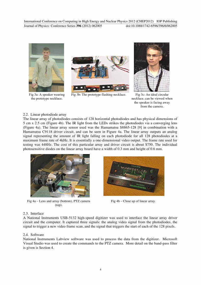
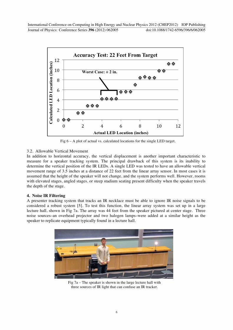
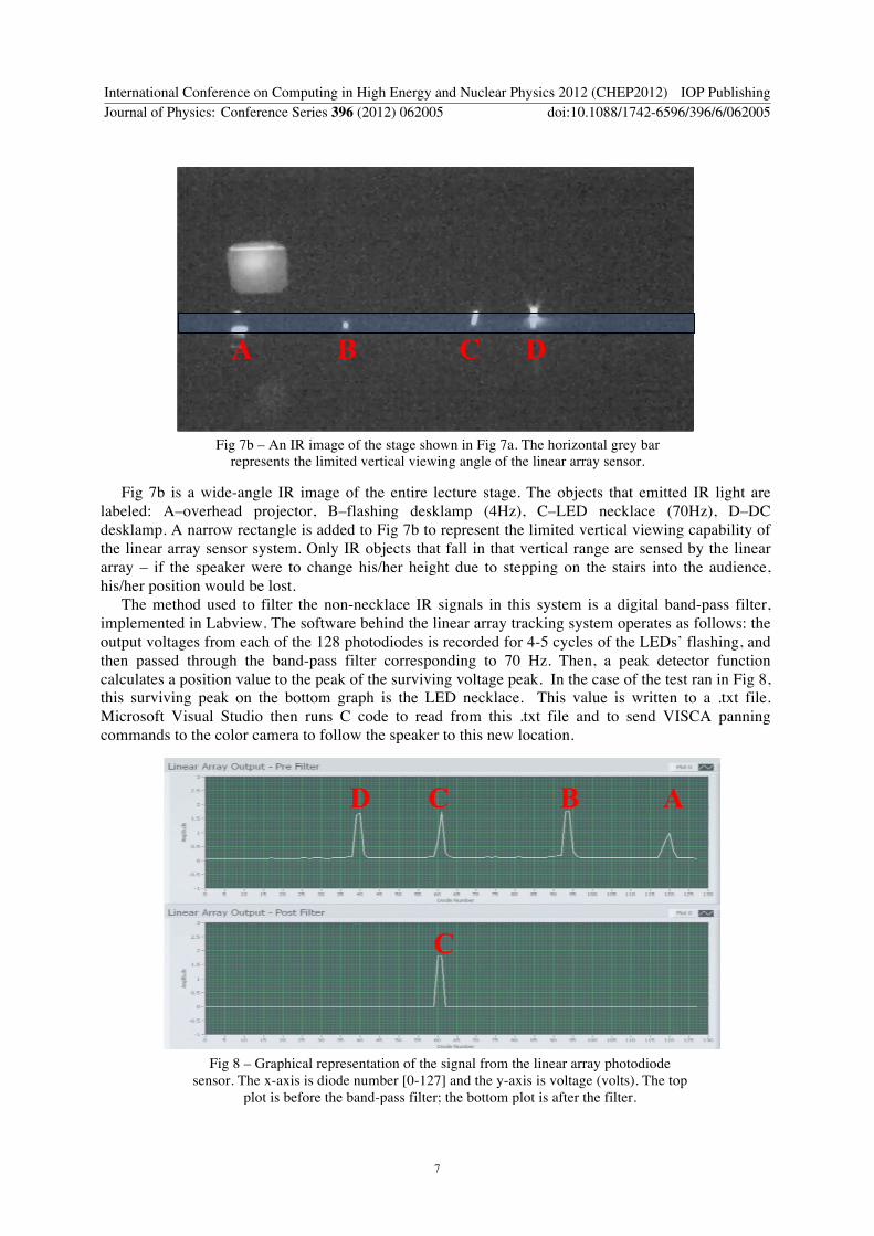
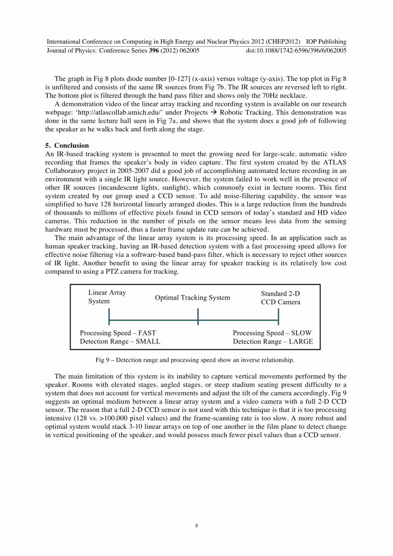