Embed Size (px)
Citation preview

For Comments Only
DRAFT INDIAN STANDARD
LINE PIPE- SPECIFICATION ICS NO. 75.200;77.140.75
Not to be reproduced without the Last date for receipt of permission of BIS or used as STANDARD comments is 06 03 2006 FORWORD This draft standard has been formulated by amalgamating IS 1978:1982 ‘Specification for line pipe (second revision)’ and IS 1979:1985 ‘Specification for high-test line pipe (second revision). IS 1978 was first published in 1961 and was subsequently revised in 1971 and 1982 whereas IS 1979 was first published in 1961 and was subsequently revised in 1971 and 1985. Since these are related standards, it was decided to amalgamate these two into one in line with API 5L 2004 Specification for line pipe, American Petroleum Institute. After publication of this standard IS 1979 shall be withdrawn. The sizes used in this revision are dimensionless designations, which are derivd from the specified outside diameter as measured and provide a convenient method of referencing pipe size within the text and tables. Pipe sizes 23/8 and larger are expressed as integers and fractions; pipe sizes smaller than 23/8 are expressed to three decimal places. These sizes replace the size designation’ and the nominal size designation’ used in the IS 1978 and IS 1979. This draft standard contains clause 3.2.1, 3.2.2, 5.6, 7.2, 8.1, 8.1.2, 9.2 b), 9.3.4, 15.1, 16.1, 18.2, 19.1, 19.3, A-3.3 b), A-3.4, A-6.3, D-1.2, which call for agreement between the purchaser and the manufacturer. In the preparation of this draft standard assistance has been derived from the following publication: API 5L 2004 Specification for line pipe, American Petroleum Institute. For the purpose of deciding whether a particular requirement of this standard is complied with, the final value, observed or calculated, expressing the result of a test or analysis, shall be rounded off in accordance with IS 2:1960 ‘Rules for rounding off numerical values (revised). The number of significant places retained in the rounded off value should be the same as that of the specified value in this standard. 1 SCOPE

This draft Indian Standard covers the requirements for seamless and welded steel line pipes. It includes plain-end, threaded-end and belled-end pipe as well as through-the-flow line (TFL) pipe and pipe with ends prepared for use with special couplings. The purpose of this specification is to provide standards for pipe suitable for use in conveying gas, water and oil in both the oil and natural gas industries. 2 REFERENCE The standards listed below contain provisions, which through reference in this text constitute provision of this standard. At the time of publication, the editions indicated were valid. All standards are subjected to revision, and parties to agreements based on this standard are encouraged to investigate the possibility of applying the most recent editions of this standard indicated below: IS No. Title 228 Methods of chemical analysis of pig iron, cast iron and plain
carbon and low alloy steels (revised) (issued in parts) 1387: 1993 General requirements for the supply of metallurgical materials
(second revision) 1608:2005 Metallic materials-Tensile temperature at ambient temperature
(second revision) 1757: 1988 Method for charpy impact test (v-notch) on metallic material
(second revision) 2328:1983 Method for flattening test on metallic tubes (first revision) 4740:1979 Code of practice for packaging of steel tubes (first revision) 6752:1991 Code of practicefor magnetic particle flaw detection of ferrous
pipes and tubes (first revision) 12278:1988 Method for ring tensile test on metallic tubes
3 TERMINOLOGY AND TYPES OF PIPE For the purpose of this standard, the following definition shall apply. 3.1 Cold Expanded Pipe – Pipe that, while at ambient mill temperature, has received a permanent increase in outside diameter or circumference of at least 0.3 percent, throughout its length, by internal hydrostatic pressure in closed dies or by an internal expanding mechanical device. Pipe furnished to this specification, except continuous welded, shall be either non-expanded or cold expanded at the option of the manufacturer, unless otherwise specified on the purchase order. Suitable provision shall

be incorporated to protect the weld from contact with the internal expanding mechanical device during mechanical expansion. 3.2 Combination Gas Metal-arc and Submerged-arc Welded Pipe – Combination gas metal-arc and submerged-arc welded pipe is defined as pipe that has one longitudinal seam produced by a combination of the welding process defined in 3.8 and 3.13. The gas metal-arc welding process shall be continuous and first, followed by the automatic submerged-arc welding process with at least one pass on the inside and at least one pass on the outside. 3.3 Continuous Welded Pipe -- Continuous welding is defined as pipe that has one longitudinal seam produced by the continuous welding process which is a process of forming a seam by heating the skelp in a furnace and mechanically pressing the formed edges together wherein successive coils of skelp have been joined together to provide a continuous flow of steel for the welding mill. This process is a type of butt-welding. 3.4 Double Seam Submerged-arc Welded Pipe – Double seam submerged-arc welded pipe is defined as pipe that has two longitudinal seams formed by automatic submerged-arc welded process defined in 3.13. The location of the seam shall be approximately 1800 apart. For each seam, at least one pass shall be on the inside and at least one pass shall be on the outside. All weld tests shall be performed after forming and welding. 3.5 Double Seam Gas Metal-arc Welded Pipe – Double seam metal-arc welded pipe is defined as pipe that has two longitudinal seams formed by gas metal-arc welded process defined in 3.8. The location of the seam shall be approximately 1800 apart. For each seam, at least one pass shall be on the inside and at least one pass shall be on the outside. All weld tests shall be performed after forming and welding. 3.6 Double Seam Combination Gas Metal-arc and Welded Pipe – Double seam combination gas metal-arc and submerged-arc welded pipe is defined as pipe that has two longitudinal seams formed by a combination of the welding processes defined in 3.8 and 3.13. The location of the seam shall be approximately 1800 apart. For each seam, the gas metalarc welding shall be continuous and first, and followedby the automatic sub-merged arc welding process with at least one pass shall be on the inside and at least one pass shall be on the outside. All weld tests shall be performed after forming and welding. 3.7 Electric Welded Pipe -- A pipe having one longitudinal seam formed by electric resistance welding or electric induction welding without the addition of extraneous metal. The weld seam of electric-resistance and induction welded pipe shall be heat treated after welding to a minimum temperature of 5380C or processed in such a manner that no untempered martensite remains. 3.8 Gas Metal-arc Welded Pipe – Gas metal-arc welded pipe is defined as pipe that has one longitudinal seam produced by continuous gas metal-arc welding process that

produces coalescence of metals by heating them with an arc or arcs between a continuous consumable electrode and the work. Shielding is obtained entirely from an externally supplied gas or gas mixture. Pressure is not used and the filler metal is obtained from the electrode. At least one pass shall be on the inside andat least one pass shall be on the outside. 3.9 Helical Seam Submerged-arc Welded Pipe – Helical seam submerged-arc welded pipe is defined as pipe that has one helical seam formed by automatic submerged-arc welded process defined in 3.13. At least one pass shall be on the inside and at least one pass shall be on the outside. This type of pipe is also known as spiral weld pipe.
NOTE 1- The width of plate or skelp used to manufacture helical seam pipe shall not be less than 0.8 ormore than 3.0 times the outside diameter of the pipe.
NOTE 2 - Junctions of skelp end welds and helical seam welds in finished pipe shall be permitted only at distances greater than 305 mm from the pipe ends. By agreement between the purchaser and the manufacturer, skelp end welds shall be permitted at the pipe ends, provided there is a circumferential separation of at least 152 mm between the skelp end weld and the helical seam weld at the applicable pipe ends. Skelp end welds in finished pipe shall be properly prepared for welding and shall be made by automatic submerged-arc welding, automatic gas metal-arc welding or a combination of both processes.
3.10 Jointer Weld – A jointer weld is a circumference seam weld that joins two pieces of pipe together. 3.11 Killed Steel -- Steel which has been fully deoxidized to reduce the oxygen content of the steel to a minimum in order that no reaction takes place between carbon and oxygen during solidification 3.12 Laser Welded Pipe – Laser welded pipe is defined as pipe that has one longitudinal seam produced by the laser welding process which is a process that uses a laser beam and a keyholding technique to produce melting and coalescence of the edges to be welded. The edges may be preheated. Shielding is obtained entirely from an externally supplied gas or gas mixture 3.13 Longitudinal Seam Submerged Arc Welded Pipe – Longitudinal seam submerged –arc welded pipe is defined as pipe that has longitudinal seam produced by the automatic submerged-arc welding process which is a process that produces coalescence of metals by heating them with an arc or arcs between a bare metal consumable electrode or electrodes and the work. The arc and molten metal are shielded by a blanket of granular, fusible material on the work. Pressure is not used and part or all of the filler metal is obtained from the electrode. At least one pass shall be on the inside andat least one pass shall be on the outside. 3.14 PSL 1 Electric welded Pipe – For grades higher than YSt 290 (X42), the weld seam and the entire heat affected zone shall be heat treated so as to simulate a normalizing heat treatment (see note), except that by agreement between the purchaser and the manufacturer alternative heat treatments or combinations of heat treatment and chemical compositions may be substituted. Where such substitutions are made, the

manufacturer shall demonstrate the effectiveness of the method selected using a procedure that is mutually agreed upon. This procedure may include, but is not necessarily limited to, hardness testing, microstructural evaluation, or mechanical testing. For Grades YSt 290 (X42) and lower, the weld seam shall be similarly heat treated, or the pipe shall be processed in such a manner that no untempered martensite remains.
NOTE- During the manufacture of electric welded pipe, the product is in motion through the surrounding air. Normalizing is usually defined with “cooling in still air”, hence the phrase “to simulate a normalizing heat treatment” is used here.
3.15 PSL 2 Electric Welded Pipe – Electric welding shall be performed with a minimum welded frequency of 100 kHz. For all grades, the weld seam and the entire heat affected zone shall be heat treated so as to simulate a normalizing heat treatment (see Note in 3.14), except that by agreement between the purchaser and the manufacturer alternative heat treatments or combinations of heat treatment and chemical composition may be substituted. Where such substitutions are made, the manufacturer shall demonstrate the effectiveness of the method selected using a procedure that is mutually agreed upon. This procedure may include, but is not necessarily limited to, hardness testing, microstructural evaluation, or mechanical testing. NOTE- The plate or skelp used for PSL 2 pipe shall not contain any repair welds. 3.16 Seamless Pipe -- Seamless pipe is defined as wrought steel tubular product made without a welded seam, manufactured by hot working of steel or, if necessary, by subsequently cold finishing the hotworked tubular product (see 2.1 of IS 1979) to produce the desired shape, dimensions and properties 3.17 Skelp End weld – A skelp end weld is a seam weld that joins plate or skelp ends together in helical seam pipe. 3.18 Tack Weld – A tack weld is a seam weld used to align the abutting edges until the final seam welds are produced . Tack welds shall be made by manual or semi-automatic submerged-arc welding, electric welding, gas metal-arc welding, flux cored arc welding, or shielded metal-arc welding using low hydrogen electrodes. Tack welds shall be removed by machining or remelting during subsequent welding of the seam. 4. PRODUCT SPECIFICATION LEVEL 4.1 Product Specification Level (PSL) – This specification establishes requirements for two product specification levels (PSL 1 and PSL 2). These two PSL designations define different levels of standard technical requirements. PSL 2 has mandatory requirements for carbon equivalent, notch toughness, maximum yield strength and maximum tensile strength. These and other differences are summarized in Table 1. Requirements that apply to only PSL 1 and PSL 2 are so designated. Reqirements that are not designated to a specific PSL apply to both PSL 1 or only PSL 2. The purchaser may add requirements to purchase orders for either PSL 1 or PSL 2, as provided by the supplementary requirements in Annex A.

4.2 GRADE Line Pipes shall be of the following types and grades; Type of Pipe Grades Seamless YSt 172 (A25), YSt 207 (A), YSt 241 (B), YSt 290 (X42), YSt
317 (X46), YSt 359 (X52), YSt 386 (X56), YSt 414 (X60), YSt 448 (X65), YSt 483 (X70) and YSt 552 (X80)
Welded -Do-
PSL 1 pipe can be supplied in Grade YSt 172 through YSt 483. PSL 2 pipe can be supplied in Grade YSt 241 through YSt 552. Pipe manufactured as Grade YSt 414 or higher shall not be substituted for pipe ordered as Grade YSt 359 or lower without purchaser approval. 5 MATERIAL & MANUFACTURE 5.1 The steel used for the manufacture of pipes shall be made by electric arc furnace or basic oxygen processes. The steel used for the manufacture of pipes shall be fully killed and fine grained with grain size of 7 or finer as per IS 4748:1988 for PSL 2 only. 5.2 Pipe furnished to this specification shall be either seamless or welded as defined in 3 and shall be limited to the product specification levels, grades, types of pipe and size limitations specified in Table 2.
Table 1- Summery Of Differencess Between PSL 1 And PSL2 (Clause 4.1)
Parameter PSL1 PSL2 Grade range YSt 172 through YSt 483 YSt 241 through YSt 552 Size range 0.405 through 80 41/2 through 80 Type of pipe ends Plain-end, thread-end;
Belled-end: special coupling pipe
Plain-end
Seam welding All methods:continuous welding limited to Grade YSt 172
All methods except continuous and leser welding
Electric welds: welder frequency
No minimum 250 kHz minimum
Heat treatment of electric welds
Required for grade less than YSt 290
Required for all grades (YSt 241 through YSt 552)
Chemistry: max C for seamless pipe
0.28 % for grade ≥ YSt 241 0.24 %
Chemistry: max C for welded pipe
0.26 % for grade ≥ YSt 241 0.24 %
Chemistry: max P 0.030 % for grade ≥ YSt 0.025 %

207 Chemistry: max S 0.030 % 0.015 % Carbon equivalent: Only when purchase
specified SR 18 Maximum required for each grade
Yield strength, maximum None Maximum for each grade UTS, maximum None Maximum for each grade Fracture toughness None required Required for all grades Nondestructive inspection of seamless
Only when purchaser specified SR 4
SR 4 mandatory
Repair by welding of pipe body, plate ansd skelp
Permittee Prohibited
Repair by welding of weld seams without filler metal
Permitted by agreement Prohibited
Certification Certification when specified as per SR 15
Certiificates (SR 15.1) mandatory
Tracability Tracable only until all tests are passed, unless SR 15 is specified.
Tracable after completionof tests (SR 15.2) mandatory
5.3 Repairs by Welding of Plate or skelp (PSL 2 only) – The plate or skelp used for PSL 2 pipe shall not contain any repair welds. 5.4 Heat treatment – The heat treating process shall be performed in accordance with a documented procedure. Pipe furnished to this specification may be as-rolled, normalized, normalized and tempered, subcritically stress relieved, or subcritically age hardened; and Yst 290 & above grade may be quenched and tempered. For ERW pipes, the pipe shall be produced from the skelp which shall be quenched and tempered or controlled rolled, or combined controlled rolled and accelerated cooled to uniformly fine ferritic grain structure to the finished steel. Other type of heat treatment shall be by agreement between purchaser and manufacturer. 6 SUPPLY OF MATERIAL General requirements relating to the supply of line pipes shall be as given in IS 1387: 1993 7 CHEMICAL COMPOSITION 7.1 The composition of steel used for the manufacture of pipe furnished to this specification shallconform to the chemical requirements given in Table 3A (for PSL 1) orTable 3B (for PSL 2). Table 3A – PSL 1 Chemical requirements for heat and product analysis, percentage of mass

(Clause 7.1) Grade &
Class Carbon
Max Manganes
Max Phosphorus Min Max
Sulphur Max
Titanium Max
Seamless (1) (2) (3) (4) (5) (6)
YSt 172, Class 1
0.21 0/60 0.030 0.030
YSt 172, Class 2
0.21 0.60 0.045 - 0.080 0.030
YSt 207 0.22 0.90 0.030 0.030 YSt 241 0.28 1.20 0.030 0.030 0.04 YSt 290 0.28 1.30 0.030 0.030 0.04
YSt 317, 359& 386
0.28 1.40 0.030 0.030 0.04
YSt 414 0.28 1.40 0.030 0.030 0.04 YSt 448 &
483 0.28 1.40 0.030 0.030 0.06
Welded YSt 172, Class 1
0.21 0.60 0.030 0.030
YSt 172, Class 2
0.21 0.60 0.045 0.080 0.030
YSt 207 0.22 0.90 0.030 0.030 YSt 241 0.26 1.20 0.030 0.030 0.04 YSt 290 0.26 1.30 0.030 0.030 0.04
YSt 317, 359, 386,
0.26 1.40 0.030 0.030 0.04
YSt 414 0.26 1.40 0.030 0.030 0.04 YSt 448 0.26 1.45 0.030 0.030 0.06 YSt 483 0.26 1.65 0.030 0.030 0.06 Table 3B PSL 2 Chemical requirements for heat and product analysis, percentage of mass (Clause 7.1) Elements Product analysis, Percent Carbon 0.16, Max Manganese 1.6 5, Max Silicon 0.15-0.45 Sulphur 0.015, Max Phosphorus 0.025, Max Aluminium 0.07, Max Chromium 0.2, Max Molyebdenum 0.1, Max Copper 0.35, Max Nickel 0.2, Max Nitrogen 0.012, Max

Boron 0.0005, Max NOTE 1 i) Niobium, vanadium or combinations thereof may be used at the discretion of the manufacturer and the sum of niobium,vanadium and titanium contents shall not exceed 0.15 percent ii) Cu + Ni shall not exceed 0.40 percent iii) Al / N ratio shall be 2 Min iv) For Grade YSt 552 (X80), the manganese (Mn) content shall be 1.40 % Max for seamless pipes and 1.85 % max for welded pipes. NOTE 2 – If alloying elements other than those specified in Table 2B above are added to the steel, the limit of the additional components shall be agreed with the purchaser. NOTE 3 – Minimum for Si is not applicable for Al killed steel . 7.2 Ladle Analysis – When required by the purchaser, the manufacturer shall furnish a report giving the ladle analysis of each heat of steel. The analysis so determined shall conform to the requirements of 7.1. The analysis of steel shall be carried out either by the method specified in IS 228 and its related parts or any other established instrumental/chemical method. In case of dispute, the procedure given in IS 228 and its relevant parts shall be the reference method. However, where the method is not given in IS 228 and its relevant parts, the reference method shall be agreed to between the purchaser and the manufacturer. Where the steel mill is not a part of an integrated pipe mill, heat analysis shall be reported by Manufacturer prior to start of pipe production.
7.3 Carbon Equivalent (PSL 2 only) 7.3.1 Calculation of Carbon Equivalent -- For PSL 2 pipe, carbon equivalent (CE) calculations shall be based on the product analyses and shall be calculated as follows. All carbon equivalent results shall be reported.
a) When the carbon content is less than or equal to 0.12 percent, the carbon equivalent shall be calculated using the following formula:
CE (Pcm) = C + Si/30 + Mn/20 + Cu/20 + Ni/60 + Cr/20 + Mo/15 + V/10 + 5B
b) When the carbon content is greater than 0.12 percent, the carbon equivalent shall be calculated using the following formula:
CE (IIW) = C + Mn/6 + (Cr + Mo + V)/5 + (Ni + Cu)/15

7.3.2 Maximum Carbon Equivalent – The carbon equivalent shall not exceed the following for PSL 1 only:
CE (Pcm) � 0.25 CE (IIW) � 0.43
For the pipe of all grades, size and wall thickness, Carbon Equivalent shall compy with
the following limits for PSL 2 only:
CE (Pcm) < 0.23 percent CE (IIW) < 0.40 percent
7.4 Product Analysis –The manufacturer shall determine the analysis of two samples representing each heat of steel used for the production of pipe under this specification. 7.4.1 Seamless Pipe – At the option of the manufacturer, cuttings or drillings for product analysis shall be taken either from tensile test specimens or from the pipe at several points around the finished pipe. If drillings are used, the minimum drill size shall be 13 mm and drillings shall be taken by drilling all the way through the pipe wall. 7.4.2 Welded Pipe -- Samples used for product analysis shall be taken from finished pipes. Samples for product analysis from plate / skelp may be provided the traceability of samples is guaranteed. 7.4.3 The composition so determined shall conform to the chemical requirements given in Table 3A and Table 3B within the following permissible variation for product analysis:
Carbon, percent
i) Seamless ii) Welded
+0.03 +0.04
Manganese, percent +0.05 Phosphorus, percent +0.01
Sulpher, percent +0.01 Niobium, percent + 0.01
Vanadium, percent +0.01 Titanium, percent +0.01
7.5 Retest – If the product analysis of both lengths of pipe representing the lot fails to conform to the specified requirements, at the manufacturer’s option, either the lot shall stand rejected or all the remaining lengths in the lot shall be tested individually for conformance to the specified requirement. If only one of the two samples fails, at the manufacturer’s option either the lot shall stand rejected or two retest analyses shall be made on two additional lengths from the same lot. Both the retest analyses shall be made on two additional lengths from the same lot. If both the retest analyses conform to

the requirements, the lot shall be accepted except for the pipe, plate or skelp from which the initial sample that failed was taken. If one or both of the retest analyses fail. At the manufacturer’s option, the entire lot shall be rejected or each of the remaining lengths shall be tested individually. In the individual testing of the remaining lengths in any lot, analysis for only the rejecting element or elements need be determined. Samples for retest analyses shall be taken in the same manner as specified for product analysis. 7.6 Chemical Analysis Procedure – For the above chemical requirements, the steel shall be analyzed in accordance with IS 228 and its relevant parts or the other procedure as agreed to between the purchaser and the manufacturer. 8 MECHANICAL PROPERTIES
8.1 Tensile Properties PSL 1 Grade YSt 172 (A25), YSt 207 (A), YSt 241 (B), YSt 290 (X42), YSt 317 (X46), YSt 359 (X52), YSt 386 (X56), YSt 414 (X60), YSt 448 (X65) and YSt 483 (X70) shall conform to the tensile requirements specified in Table 4A. PSL 2 Grade YSt 241 (B), YSt 290 (X42), YSt 317 (X46), YSt 359 (X52), YSt 386 (X56), YSt 414 (X60), YSt 448 (X65), YSt 483 (X70) and YSt 552 (X80) finished pipes (after all the heat treatment and expansion or sizing operation) shall conform to the tensile requirements specified in Table 4B The actual yield strength shall not exceed the minimum YS (SMYS) limits beyond the limits specified hereunder:
Grade Permissible in excess of SMYS, Mpa Up to and including YSt 317 (X46)
131
YSt 359 (X52) to YSt 448 (X65)
152
YSt 483 (X70) 138 Other grades intermediate to the listed grades between YSt 290 (X42) and YSt 552 (X80) shall conform to tensile requirements agreed upon between the purchaser and the manufacturer and the requirements shall be consistent with those specified in Table 4A (for PSL 1 pipe) or Table 4B (for PSL 2 pipe). For cold expanded pipe, the ratio of body yield strength and body ultimate tensile strength of each test pipe on which body yield strength and body ultimate tensile strength are determined, shall not exceed 0.90, when tested using flattened tensile

specimen. For steel with a yield point specified not over 550 Mpa, the yield strength shall be the tensile stress required to produce a total elongation of 0.2 percent of the gauge length as determined by an extensometer. For yield point above 550 Mpa, this method is not valid unless the limiting total extension is increased. When elongation is recorded or reported, the record or report shall show the nominal width of the test specimen when strip specimens are used and the diameter and gauge length when round bar specimens are used, or shall state when full section specimens are used. For Grade YSt 172 (A25) pipe, the manufacturer may certify that the material furnished has been tested and meets the mechanical requirements of Grade YSt 172 (A25). The ultimate tensile strength of the weld shall be equal to or better than the specified minimum ultimate tensile strength of the base metal. The minimum elongation of base metal shall be determined in accordance with the formula given in foot note a) of Table 3B and shall comply with the minimum values as given in Annex B. However, elongation in no case shall be less than 20 percent. 8.1.1 Longitudinal Tensile Test -- The longitudinal tensile tests shall be performed for determining for all sizes of hot worked or heat-treated seamless pipe and all welded pipe in sizes smaller than 219.1 mm OD as shown in Fig. 1. 8.1.2 Transverse Tensile Test -- For seamless pipe, a transverse round bar or ring expansion specimen may be substituted for the longitudinal specimen by agreement between the purchaser and manufacturer. For welded pipe and cold expanded seamless pipe size 219.1 OD mm or larger, transverse tensile tests shall be conducted for the purpose of determining tensile properties. 8.1.3 Weld Tensile Tests – Weld tensile test specimens shall be taken at 900 to the weld with the weld at the center as shown in Fig 1 and Fig 2 and shall represent the full wall thickness of the pipe from which the specimen was cut. Weld reinforcement may be removed at the option of manufacturer. Weld tensile tests need not include determination of yield strength and elongation. 8.1.4 All longitudinal and transverse tensile tests shall include yield strength, tensile strength and elongation determination. The test shall be carried out on full section or strip cut from the selected pipes in accordance with IS 1608 and IS 12278. The testing shall be done in accordance with the test piece shown in Fig 2, at ambient temperature 8.1.5 Test Specimens-- .At the option of the manufacturer, the specimen may be either full section, strip specimen or round bar specimen as specified in 8.1.5.1, 8.1.5.2 and Fig. 2. Testing of strip specimens shall be with suitable curved-face testing grips or flat face testing grips if the grip areas of the specimens have been machined to reduce the curvature or have been flattened without heating. For strip specimens, the specified width in the gauge length shall be either 38.1 mm or 19.0 mmfor pipe of size 3 ½ or smaller; either 38.1 mm or 25.4 mm or pipe of size larger than 3 ½ up to size 6 5/8, inclusive; and 38.1 mm for pipe larger than size 6 5/8.

8.1.5.1 Longitudinal test specimens shall be either full section specimens, strip specimen (see Fig 2, subfigure B and C) or for pipe with wall thickness greater than 19.1 mm , a 12.7 mm diameter round bar specimen (see Fig. 2, subfigure D) at the option of the manufacturer. The strip specimen shall be tested without flattening. 8.1.5.2 Transverse tensile properties shall be determined at the optoin of the manufacturer, by one of the following methods:
a) The yield strength, ultimate tensile strength and elongation values shall be determined on either a flattened rectangular specimen (see Fig. 2, subfigure E) or on a 12.7 mm or 8.9 mm round bar specimen (see Fig. 2, subfigure G ).
b) The yield strength shall be determined by the ring expansion method (see Fig 2, Subfigure A) with the ultimate tensile strength and elongation values determined from a flattened rectangular specimen.
Transverse round bar specimens are to be taken from nonflattened pipe section. The test specimen size shall be as given in Table 5, unless the next larger test specimen size issused or unless the manufacturer and the purchaser agree to the use of the next smaller test specimen size. For pipe sizes too small to obtain a 6.4 mm specimen, round bar tensile test specimens shall not be used. 8.1.6 Number of TensileTests – Tensile tests shall be made at the frequency of one test per inspection lot as shown in Table 6. 8.1.7 Retests – If the tensile test specimen representing a lot of pipes fails to conform to the specified requirements, the manufacturer may elect to make re-test on two additional lengths from the same lot. If both the retest specimens conform to the requirements, all the lengths in the lot shall be accepted except the length from which the initial specimens was taken. If one or both of the re-test specimens fail to conform to the specified requirements, the manufacturer may elect to test individually the remaining lengths in the lot, in which case determinations are required only for the particular requirements with which the specimens failed to comply in the preceding tests. Specimens for retests shall be taken in the same manner as specified in 8.1.5 8.2 Flattening Test 8.2.1 Flattening test shall be performed for electric welded., continuous welded and laser welded pipe. Test specimens shall be at least 63.5 mm long cut from each length and shall be flattened between parallel plate until the opposite walls of the pipe meet (see Fig 3). The tests from each end shall be made alternatively with the weld at 00 and 900 (point of maximum bending) in accordance with IS 2328. The acceptance criteria for flattening tests shall be given in 8.2.1.1and 8.2.1.2.

8.2.1.1 For electric welded pipe in grades higher than YSt 172 (A25), and laser welded pipe smaller than 12 3/4
i) For Grade YSt 414 (X60) and higher pipe with a specified wall thickness equal to or greater than to 12.7 mm flatten to two-thirds of the original outside diameter without weld opening. For all other combinations of pipe grade and specified wall thickness, flatten to one-half of the original outside diameter without weld opening.
ii) For pipe with a D/t greater than 10, continue flattening to one-third of the original OD without cracks or breaks other than in the weld.
iii) For all pipe D/t, continue flattening until opposite walls of the pipe meets; no evidence of lamination or burnt metal shall develop during the entire test.
8.2.1.2 For Grade YSt 172 (A25) welded pipe, flatten to three-fourths of the original OD without weld fracture. Continue flattening to 60 percent of the original OD without cracks or breaks other than in the weld. Frequency of testing, sample location, test orientation and applicable size shall be as shown in Fig 3. For electric welded pipe that is to be processed through a hot stretch mill, the flattening test specimens shall be obtained either prior to or after such treatment, at the option of manufacturer.
NOTE 1- For all flattening tests, the weld extends to a distance on each side of the weld-line of 6.4 mm smaller than size2 3/8 and 12.7 mm for pipe size 2 3/8 or larger.
NOTE 2- For electric welded pipe that is processed through a hot stretch mill and is flattened prior to such treatment, the original outside diameter is as designated by the manufacturer; for all other cases, the original outside diameter is the specified outside diameter.
8.2.2 Retests – Flattening retest provisions are as follows: 8.2.2.1 Non-expanded electric welded pipe in grades higher than YSt 172 (A25)and non-expanded laser welded pipe smaller than 323.9 mm OD, produced in single lengths—The manufacturer may elect to retest any failed end until the requirements are met, provided the finished pipe is not less than 80 percent of its length after initial cropping. 8.2.2.2 Non-expanded electric welded pipe in grades higher than YSt 172 (A25) and nonexpanded laser welded pipe smaller than 323.9 mm OD, produced in multiple lengths—The manufacturer may elect to retest each end of each individual length if any test fails. Two additional lengths shall be taken from the coil in which pipe is rejected in flattening test. The retests of each end of two pipes shall be tested with the weld alternatively at 00 and 900. 8.2.2.3 Cold-expanded electric welded pipe in grades higher than YSt 172 (A25); all welded Grade YSt 172 (A25) in 73.0 mm OD and larger; and cold expanded laser welded pipe smaller than 323.9 mm OD – The manufacturer may elect to retest one end from each of two additional lengths of the same lot. If both retests are acceptable, all

lengths in the lot shall be accepted, except the original ailed length> If one or both retest fails, the manufacturers may elect to repeat the test on specimens cut from one end of each of the remaining individual lengths in the lot. 8.3 Bend Test 8.3.1 Welded Grade YSt 172 (A25) pipe of size 2 3/8 and smaller shall be tested by the following test. One full section specimen of appropriate length, cut from a length of pipe from each lot of 25 tons or fraction thereof, for pipe of nominal size 1.900 and smaller, and from each lot of 50 tons or fraction thereof, for pipe of size 2 3/8 shall be bent cold through 900 , around a mandrel having a diameter not greater than twelve times the outside diameter of the pipe being tested, with the weld located approximately 450 from the point of contact of the specimen with the mandrel. The specimen shall not crack in any portion of the pipe, and no opening shall occur in the weld.
NOTE- For all bend tests, the weld extends to a distance on each side of the weld line of 6.4 mm for pipe smaller than 2 3/8 and 12.7 mm for pipe of size 2 3/8.
8.3.2 Retests – If the specimen fails to conform to the specified requirements, the manufacturer may elect to make retests on specimens cut from the additional lengths from the same lot. If all retest specimens conform to the specified requirements, all lengths in the lot shall be accepted, except the length from which the initial specimen was taken. If one or more of the retest specimens fails to conform to the specified requirements the manufacturer may elect to repeat the test on specimens cut from the individual lengths remaining in the lot. 8.4 Guided-Bend Test 8.4.1 Submerged-arc and gas metal-arc welds in pipe of all sizes, and laser welds in pipe of sizes 12 ¾ and larger, shall be tested by the guided-bend test. The test specimen shall be taken from the helical or each longitudinal seam weld in a length of pipe from each lot of 50 length or less of each combination of specified outside diameter, specified wall thickness, and grade; and from a skelp end weld in a length of pipe from each lot of 50 lengths or less of each combination of specified outside diameter, specified wall thickness, and grade of finished helical seam pipe containing skelp end welds. The test specimens shall not contain repair welds. 8.4.2 One face bend and one root bend specimen, both conforming to Fig 4 shall be bent approximately 1800 in jig substantially in accordance with Fig. 5. For any combination of diameter, wall thickness and grade, the maximum value of jig dimension A in Fig 5 may be calculate by the formula given. The manufacturer shall use a jig based on this dimension or a smaller dimension at his option. However to minimize the number of jigs required, standard values for dimension A have been selected for pipe size of 323.9 mm OD and larger. These values are listed for each size, wall thickness and grade in Annex C. For intermediate grades or specified wall thickness, the next smaller standard value for dimension A shall be used. When the dimension A is greater than 228.6 mm, the length of the specimen required to contact the male die need not exceed 228.6 mm. For pipe with wall thickness over 19.1 mm, a reduced wall specimen

as shown in Fig 5 may be used at the option of the manufacturer. Reduced wall specimens shall be tested in a jig with the A dimension calculated for pipe of wall thickness 19.1 mm of the appropriate size and grade. 8.4.3 The specimen shall not (a) fracture completely, (b) reveal any crack or rapture in the weld metal greater than 3.2 mm in length regarding of depth, and (c) reveal any crack or rapture in the parent metal, the heat affected zone or the fusion line longer than 3.2 mm and deeper than 12.5 percent of the specified wall thickness; except cracks which occur at the edges of the specimen and which are less than 6 mm long. These shall not be the cause for rejection in (b) and (c) regardless of depth. If the fracture or crack in the specimen is caused by a defect or flaw, the specimen may be discarded and a new specimen substituted. 8.4.4. Retests – If one or both of the guided bend specimens fail to conform to the specified requirements, the manufacturer may elect to repeat the tests on specimens cut from two additional lengths of pipe from the same lot. If such specimens conforms to the specified requirements ,all the lengths in the lot shall be accepted, except the length initially selected for test. If any of the retest specimens fail to pass the specified requirements, the manufacturer may elect to test specimens cut from the individual length remaining in the lot. The manufacturer may also elect to retest any length, which has failed to pass the test by cropping back and cutting two additional specimens from the same end. If the requirements of the original test are met by both of these additional tests, this length shall be acceptable. No further cropping and retesting is permitted. Specimens for retests shall be taken in the same manner as specified in 8.4.2 8.5 Fracture Toughness Tests 8.5.1 Charpy Impact (V-notch) Test – For PSL 1 pipe, Charpy impact testing is not required. For pipe in the size and wall thickness combination given in Table 7. Charpy V-notch tests shall be conducted by the method specified in IS 1757. It shall be permissible to use 2/3 or ½ size test specimens as required when the absorbed energy is expected to exceed80 percent of the full scale capacity of the testing machine. The Charpy specimens shall be taken from the body of the pipe. For welded pipe, the location shall be 900 from the weld seam. Notch orientation shall be through the wall thickness as shown in Fig A-3 of Annex A. The minimum test frequency shall be one test per heat per combination of pipe size and specified wall thickness. An impact test shall consist of three individual specimen values and the average of the three specimens. The test temperature shall 00C, however, pipe tested at a lower temperature is also acceptable if it meets all other applicable fracture toughness requirements as stated below: 8.5.1.1 For all grades, the required minimum average (set of three specimens) absorbed energy for each heat based on full size specimens shall be 27 J for transverse specimens or 41 J for longitudinal specimens, whichever is applicable per Table 7.

8.5.1.2 For all grades, the shear area of each specimen shall be reported for each heat. 8.5.1.3 For grade YSt 552 (X80) only, the required minimum all-heat average absorbed energy for the entire order item, based on full size Charpy specimens shall be 68 J (50 ft-lb) for transverse specimens; or 101 J for longitudinal specimens, whichever is applicable for Table 7. If the all-heat average of the does not meet the applicable requirement, the manufacturer shall be responsible for the replacement of heats to bring the average up to the required level. 8.5.1.4 For grade YSt 552 (X80) only, the required minimum shear area shall be either 40 percent for each heat and 70 percent for the all-heat average of order based on the charpy test, or 40 percent for each heat and 60 percent for the all-heat average on the drop weight tear test as given in Annex A. The drop-weight tear test is applied for welded pipe in size 508.0 mm or larger. If the all-heat average of the order does not meet the required percentage of shear area, the manufacturer shall be responsible for the replacement of heats as necessary to bring the average up to the required level. 8.5.2 Retests – In the event that a set of Charpy test specimen fails to meet the acceptance criteria, the manufacturer may elect to replace the lot of material involved or alternatively to test two more lengths from that lot. If both of the new tests meet the acceptance criteria, then all pipes in that heat, with the exception of the original selected length, shall be considered to meet the requirement. Failure of either of the two additional tests shall require testing of each length in the lot for acceptance. 8.5.3 Supplementary Fracture Toughness Tests – In addition to the requirements in 8.5.1, when so specified in the purchase order, the manufacturer shall conduct fracture toughness tests in accordance with supplementary requirement SR 5 and SR-6 (see Annex A) or any combination of these, and shall furnish a report of results showing compliance with the specified supplementary requirements. 8.6 Metallographic Examination – For PSL 1 electric welded pipe in grades higher than YSt 290 (X42), for PSL 2 electric welded pipe in all grades, and for laser welded pipe in all grades, full body normalized pipe excluded, compliance with the requirement in 3.2 and 3.4 to heat treat the entire heat affected zone shall be demonstrated by metallographic examination of a weld cross section. Such examinations shall be performed at least once per operating shift (12 hours maximum) and whenever changes of grade, diameter, or wall thickness are made whenever significant excursions from operating heat treatment conditions are encountered. 8.7 Additional Requirements For Electric Resistance/Electric Induction Welded Line Pipe (PSL-2) 8.7.1 Reverse Bend Tests Reverse bend tests shall be performed on the pipe piece cut from the crop end from the front end of the first length and the back end of the last length produced from each coil.

The specimen shall be 100mm to 115mm long and shall be reverse bend tested in accordance with procedure given below (Fig 6) and
8.7.1.1 Selection of Mandrel - The reverse bend test shall be carried out with a mandrel, whose radius(R), width(A) shall be calculated for any combination of diameter, wall thickness and grade with the formula. 1.4 (D - t) t A = 2R = ————— - t
e(D-2 t )-1.4t where D - Outside diameter of pipe t - Wall thickness of pipe 1.4 - Peaking factor e - Strain
Minimum values of 'e' shall be as follows: -----------------------------------------------------------------------------------------------------------
Grade of Steel Min, 'e' value ------------------------------------------------------------------------------------------------------------ YST 241 (B) 0.1425
YST 290 (X-42) 0.1375 YST 317(X-46) 0.1325 YST 359(X-52) 0.1275 YST386 (X- 56 ) 0.1175 YST 414(X- 60) 0.1125 YST 448(X- 65) 0.1100 YST 483(X- 70) 0.1025 YST 552(X- 80) 0.0900

8.7.1.2 Procedure - The mandrel is to be plugged into the specimen, with the weld in contact with mandrel, to such a depth that the angle of engagement between mandrel and specimen reaches 600 (see Fig. B1). If the combination of diameter and wall thickness of pipe, and radius of mandrel is such that the angle of engagement does not reach 600, the mandrel shall be plugged into the specimen until opposite walls of the specimen meet. 8.7.1.3. Acceptance Criteria - A specimen which fractures completely prior to the specified engagement of mandrel and specimen, or which reveals cracks and ruptures in the weld or heat affected zone longer than 4mm, shall be rejected. Cracks less than 6mm long at the edges of the specimen shall not be cause for rejection. 8.7.2 Micrographic and Hardness Examination
A test specimen shall be taken across the longitudinal weld from one length of finished pipe from each lot of maximum 50 lengths from the same heat manufactured from the same process. These specimens shall be polished and etched for micro-examinations. The examinations shall provide evidence that heat treatment of weld zone is adequate and there is no untempered martensite left. The Manufacturer shall make hardness measurements on each specimen as indicated in Fig. 7 in accordance with IS 1501/ISO 6507-1. The maximum difference in hardness between base material and any reading taken in the heat affected zone shall be less than 80 points Vicker's HV10.

9 DIMENSIONS, WEIGHTS, LENGTHS, DEFECTS AND END FINISHES 9.1 Dimensions – The sizes used herein are dimensionless designations, which are derived from the specified outside diameter and provide a convenient method of referencing pipe size within the text and tables (but not for order descriptions). Pipe size 2 3/8 are expressed to three decimal places. Users of this specification who are accustomed to specifying nominal sizes rather than OD sizes are advised to familiarize themselves with these new size designations used in this specification, especially the usage in Tables 8,9. PSL 1 pipe can be supplied in sizes ranging from 0.405 through 80. PSL 2 pipe can be supplied in sizes ranging from 4 ½ to 80. Dimensional requirements on threads and thread gauges, stipulations on gauging practice, gauge specifications and certification, as well as instruments and methods for inspection of threads are given in API Std 5B and are applicable to threaded products covered by this specification.

9.2 Specified Dimensions and weights of line pipes shall be in accordance with one of the following:
a)As given in Table 8, 9, 10A, 10B or 10C whichever is applicable. By agreement between the purchaser and the manufacturer, intermediate to the values given in Table 10A, 10B or 10C, whichever is applicable. 9.3 Tolerances – The tolerances on outside diameter, wall thickness, weight, length and straightness shall conform to the limits specified in 9.3.1, 9.3.2, 9.3.3, 9.3.4 and 9.3.5 respectively. 9.3.1 Outside Diameter – The outside diameter of pipe body, as determined by tapping the circumference, shall not deviate by more than the values given below:
Size Tolerance > 2 3/8 + 0.8 mm > 2 3/8 and < 4 ½ (Continuous welded )
+ 1.0 mm
> 4 1/2 and < 16 (406.4 OD) + 2.5 mm > 16 and < 20 (508 mm OD) + 3.0 mm > 20 and < 36 (914.4 mm OD) + 3.0 mm(subject to 0.25 % of
specified OD) > 36 + 3.0 mm
9.3.1.1 Pipe end – The diameter tolerances for the pipe ends indicated in Table 10. Table 11 shall be applicable on the inside diameter. The outside diameter based on the circumferential measurement over a length of 100 mm from the end shall comply with the tolerance specified in Table 10. Inside diameter shall be calculated as ID = (OD –2WT) where ID, OD &WT are the inside diameter, specified outside diameter and specified wall thickness respectively. 9.3.1.2 Out of roundness – Out of roundness : Both ends of each pipe should be checked using an internal ring gauge and externaldiameter of pipe which shall not less than: a) Pipe ID minus 1.6 mm for < 273 mm OD b) Pipe ID minus 2.4 mm for 323 < OD > 457 mm OD c) Pipe ID minus 5.0 mm OD for > 508 mm OD Each pipe shall be measured for conformance to the above requirements. All dimensions and tolerance shall be measured and recorded at least 3 times per operating shift (12 hours maximum) .

9.3.2 Wall Thickness – Each length of pipe shall be measured for conformity to the specified wall thickness requirement. Wall thickness measurements shall be made with a mechanical caliper or with a properly calibrated nondestructive inspection device of appropriate accuracy. In case of dispute, the measurement determined by use of the mechanical caliper shall be binding. The mechanical caliper shall be fitted with contact pins having circular cross section of 6.4 mm diameter. The end of the pin contacting the inside surface of the pipe shall be rounded to a maximum radius of 38.1 mm for pipe of size 6 5/8 or larger, and to a maximum radius of d/4 for pipe of smaller than size 6 5/8, with a minimum radius of 3.2 mm .The end of the pin contacting the outside surface of the pipe shall be either flat or rounded to a radius of not less than 38.1 mm. The wall thickness of each pipe shall be checked along the circumference at both endsand at the mid location pipe at 12 o’clock, 3 o’clock, 6 o’clock and 9 o’clock position. The tolerance on specified wall thickness shall be as given below. Wall 23/8 thickness shall be measured and recorded at least 3 times per operating shift (12 h maximum)
Tolerance on Wall Thickness (Percent of Specified Wall Thickness)
Size Type of Pipe Grade B or Lower Grade X 42 or Higher
< 2 � All + 20.0, – 12.5 + 15.0, – 12.5 > 2 � and < 20 All + 15.0, – 12.5 + 15.0, – 12.5 > 20 Welded + 17.5, – 12.5 + 19.5, – 8.0 > 20 Seamless + 15.0, – 12.5 + 17.5, – 10.0 * Where negative tolerances smaller than those listed are specified by the purchaser, the positive tolerance shall be increased to the applicable total range in percent less thickness negative tolerance. 9.3.3 Mass - For plain-end pipe, the tolerance on calculated mass shall be as specified in Table 12. For threaded-and- coupled pipe, the tolerance on calculated or adjusted calculated mass shall be as specified in Table 11. Full-length calculated mass shall be determined in accordance with the following equation: WL = ( wpe x L )+ ew Where WL = calculated mass of a piece of pipe of length L , kg wpe = plain-end mass per unit length rounded to the nearest 0.01 kg/m L = length of pipe, including end finish, as defined in 9.3.4, m ew = weight gain or loss due to end finish kg. For plain-end pipe,

ew is equal to 0. the plain-end weight per unit length, wpe shall be calculated using the following equation and rounded to the nearest 0.01 kg/m SI unit equation (kg/m) = wpe = 0.024 66 (D - t) t Where D = specified outside diameter in mm, t = specified wall thickness in mm, Each length of pipe of size 5 9/16 or larger shall be weighted separately; length of pipe smaller than size 5 9/16 shall be weighed either individually or in convenient groups, at the option of the manufacturer. For all sizes of pipe, the order item weights and , where applicable, the carload weights shallbe determined. Threaded-and-coupled pipe shall be weighed with couplings screwed on but without thread protectors, except for carload determinations for which proper allowance shall be made for the weight of the thread protectors. Threaded-and-coupled pipe may be weighed before the couplings. 9.3.4 Length – Unless otherwise agreed upon between the purchaser and the manufacturer, pipes shall be furnished in single random lengths or double random lengths as specified by the purchaser. Tolerances on the length shall be as specified in Table 13. For threaded-and-coupled pipe, the length shall be measured to the outer face of the coupling. The length of threaded-and-coupled pipe may be determined before the couplings are attached, provided that proper allowance is made for the length of the couplings. Each length of pipe shall be measured, except that pipe made in lengths that are uniform within 0.03 m need not be individually measured, provided that the accuracy of the length is verified at least once per 4 hours per operating shift. The accuracy of length measuring devices for lengths of pipe less than 30 m shall be + 0.03 m . 9.3.5 Straightness – The deviation from a straight line for all pipe size shall not exceed 0.2% ofpipe length. Each pipe shall be checked for conformance to this requirement. Straightness shall be measured and recorded at least 3 times per operating shift (12 hours maximum). 9.3.6 Jointers – By agreement between the purchaser and the manufacturer, skelp end welds in finished pipe shall be permitted at jointer welds, provided that there is a circumferential separation of at least 152.4 mm between the junction of the skelp end weld and the jointer weld and the junction of the helical seam and the jointer weld. 10 PIPE ENDS

10.1 General – The pipe ends shall be plain, threaded, belled or prepared special coupling. Helical seam pipe shall not be threaded. The inside and outside edges of the ends of all pipes shall be free of burrs. 10.2 Threaded Ends (PSL 1 Only) – Threaded ends shall conform to the threading, thread inspection and gauging requirements specified in API Std 5B. One end of each length of threaded pipe shall be provided with a coupling conforming to the requirements of 12, in effect at the date of manufacture of each coupling (see Note 1) and the other end with thread protection conforming to the requirements of 17.2. Coupling shall be screwed onto the pipe handling-tight (see Note 2), except that they shall be applied power-tight if so specified on the purchase order. A thread compound shall be applied to cover the full surface of either the coupling or pipe engaged thread before making up the joint. All exposed threads shall be coated with this thread compound. Unless otherwise specified on the purchase order, the manufacturer may use any thread compound that meets the performance objectives set forth in API RP 5A3. a storage compound of distinct colour may be substituted for this thread compound on all exposed threads. Whichever compound is used shall be applied to a surface that is clean and reasonably free of moisture and cutting fluids.
NOTE 1 — Unless otherwise specified on the purchase order, it is not mandatory that both the pipe and coupling of each threaded and coupled product be manufactured to the same edition of this specification.
NOTE 2 -- Handling-tight shall be defined as sufficiently tight that the coupling cannot be removed except by using a wrench. The purpose of making up couplings handling-tight is to facilitate removal of the couplings for cleaning and inspecting threads and applying fresh thread compound before laying the pipe. This procedure has been found necessary to prevent thread leakage, especially in gas lines, because manufacturer-applied couplings made up power-tight, alt6hough leak-proof at the time of makeup, may not always remain so after transportation, handling and laying
10.3 Plain Ends – Unless specified otherwise, plain-end pipes shall be furnished with ends beveled to an angle of 300 ( +50 - 00 ) measured from a line drawn perpendicular to the axis of the pipe, and with a root face of 1.6 + 0.8 mm the pipe ends shall have all burrs removed from both the inside and outside edges. For seamless pipes, where internal machining is required to maintain the root face tolerance, the angle of the internal taper measured from the longitudinal axis shall not be larger than that listed below:
Specified Wall Thickness Maximum Angle of Taper, deg
Less than 10.6 mm 7 10.6 mm to 14.1 mm 9.5 14.1 mm to 16.9 mm 11
Over 16.9 mm 14
For removal of internal burr on welded pipe of 114.3 mm outside diameter and larger, the internal taper measured from the longitudinal axis, shall not be larger than 70 For pipe size 2 3/8 and larger, the ends shall be cut square within 1.6 mm measured not less than 4 hours per operating shift.

Both ends of pipe with filler metal welds shall have the inside reinforcement removed for a distance of approximately 101.6 mm from the end of the pipe. 10.4 Belled Ends (PSL 1 Only) – If so required by the purchaser, pipe with specified wall thickness 3.6 mm and less shall be furnished with one end belledfor bell and spigot joints in accordance with Fig 8. the belled end shall be visually inspected for workmanship and defects.
10.5 Ends prepared for Special Couplings (PSL 1 only) – If so required by the purchaser, pipe shall be furnished with ends suitable for use with special couplings such as Dresser, Victaulic or other equivalent special couplings. Such pipe shall be sufficiently free from indentations, projections or roll marks for a distance of 203 mm from the end of the pipe to permit proper makeup of coupling. 11 WORKMANSHIP AND FINISHES 11.1 Imperfection of the following types shall be considered poor workmanship. Pipes containing such imperfections shall be rejected. The manufacturer shall take all reasonable precautions to minimize re-occurring damage to the pipe. 11.2 Dents -- The pipe shall contain no dent greater than 6.4 mm measured as the gap between the lowest point of the dent and a prolongation of the original contour of the pipe. The length of the dent in any direction shall not exceed one-half of the pipe diameters. All cold-formed dents deeper than 3.2 mm with a sharp bottom gouge shall be considered a defect. The gouge may be removed by grinding. 11.3 Offset of Plate Edges – For pipe with filler metal welds with wall thickness 12.7 mm or less, the radial offset (misalignment) of plate edges in the weld seams shall not be greater than 1.6 mm . For pipe with filler metal welds with wall thickness over 12.7 mm, the radial offset shall not be greater than 0.125 t or 3.2 mm whichever is smaller. For electric welded pipe, the radial offset of plate edges plus flash trim shall not be greater than 1.5 mm . for laser welded pipe, the radial offset of plate edges plus weld reinforcement trim shall be no greater than 1.5 mm 11.4 Out-of-line Weld Bead for Pipe with Filler Metal Welds – A misalignment of weld seam exceeding 3.5 mm shall be rejected. The misalignment shall be measured on radiographic film and calculated using the formula (a+b) / 2 where a and b are the relative offset of the outside edges of the seam Fig 9. All pipes shall be checked for out of line weld bead and shall be measured and recorded at least 3 times per operating shift (12 hours maximum). (GAIL will modify the clause along with figure) 11.5 Height of Outside and Inside Weld Bead (Submerged Arc Welds) – The weld bead shall not extend above the prolongation of the original surface of the pipe by more than the amount listed below:
Wall Thickness, mm Maximum Height of Weld Bead, mm

12.7 mm 3.2 mm
Over 12.7 mm 4.8 mm Weld beads higher than permitted by the requirements of this paragraph may be ground to acceptable limits at the option of the manufacturer. The height of the weld bead shall in no case come below a prolongation of the pipe (outside or inside the weld bead) except that contouring by grinding.
11.6 Height of Weld Bead of Electric Welded Pipe – The inside weld bead (flash) of electric welded pipe shall not extend above the prolongation of the original inside surface of the pipe by more than 1.5 mm. In case the bead height is maintained within 1.5 mm, no inside trimming of weld bead shall be necessary. The outside weld bead of electric welded pipe shall be trimmed to an essentially flush condition. 11.7 Height of Weld Reinforcement of Laser Welded Pipe – The inside weld reinforcement of laser welded pipe shall not extend above the prolongation of the original inside surface of the pipe by more than 1.5 mm. In case the reinforcement height is maintained within 1.5 mm, no inside trimming of weld bead shall be necessary. The outside weld reinforcement of laser welded pipe shall be trimmed to an essentially flush condition. Laser welds may have underfills, which are acceptable within the limits of 11.12. 11.8 Trim of Inside Weld Bead of Electric Welded Pipe and Trim of Inside Weld Reinforcement of Laser Welded Pipe – The depth of groove resulting from removal of internal weld bead (flash) of electric welded pipe or removal of the internal weld reinforcement of laser welded pipe shall not be greater than the amount listed below:
Wall Thickness, mm Maximum depth of Trim, mm
3.8 mm or less 0.10 t More than 3.8 mm and less than 7.6
mm
0.4 mm Equal or more than 7.6 mm 0.05 t
Depth of groove is defined as the difference between the wall thickness measured approximately 25mm from the weld line and the remaining wall under the groove.
11.9 Hard Spots – Any hard spot having a minimum dimension greater than 50.8 mm in any direction and a hardness greater than or equal to HRC (327 HB) or 248 HV shall be removed as a cylinder.
11.10 Cracks, Sweats and Leaks – All cracks, sweats and leaks shall be considered defects.

11.11 Laminations – a lamination is an internal metal separation creating layers generally parallel to the surface. Any lamination or inclusion extending into the face or bevel of the pipe and having a visually determined transverse dimension exceeding 6.4 mm is considered a defect. Pipe containing such defects shall be cut back until no lamination or inclusion is greater than 6.4 mm. 11.12 Arc Burns – Arc burns, defined as localized points of surface melting caused by arcing between electrode or ground and pipe surface, shall be considered defects.
Dispositions of pipe containing arc burn shall be in accordance with 12 except that removal of defects by grinding shall be subject to the following additional condition. Arc burns may be removed by grinding, chipping or machining. The resultant cavity shall be thoroughly cleaned and checked for complete removal of damaged material by etching with a 10 percent solution of ammonium persulphate or a 5 percent solution of nital.
NOTE - Contact marks, defined as intermittent marks adjacent to the weld line, resulting from the electrical contact between the electrodes supplying the welding current and the pipe surface are not defects.
11.13 Undercuts – Undercutting on submerged arc welded pipe is the reduction in thickness of the pipe wall adjacent to the weld where it is fused to the surface of the pipe. Undercutting may be located and measured visually. a) Minor undercutting on either the inside or the outside of the pipe is defined as follows and is acceptable without repair or grinding:
i) Maximum depth of 0.8 mm and not exceeding 12.5 percent of the specified wall thickness with a maximum length of one-half of the specified wall thickness and not more than two such undercuts in any 0.3 m(1 ft) of the weld length.
ii) maximum depth of 0.4 mm in any length
b) Undercuts longer than one-half of the wall thickness and 0.4 to 0.8 mm in depth, but not exceeding 12.5 percent of the specified wall thickness, shall be removed by grinding. Undercuts greater in depth than 0.8 mm shall be considered injurious. 11.14 Underfills – Underfills of laser welded pipe is a depression on the weld faceor root surface extending below the adjacent surface of the base metal. Underfills can best be located visually.
a) Underfills on the inside of the pipe shall be considered a defect. b) Minor underfills on the outside of the pipe are defined as follows and are
acceptable without repair or grinding :
i) Maximum depth not exceeding 5 percent of the specified wall thickness with a maximum length of two times the specified wall thickness, with a remaining wall thickness of 87.5 percent of the specified wall thickness and not more than two such underfills in any 0.3 m of weld length.

Furthermore, the coincident combination of underfills, other imperfections, grinds and weld trim on the outside and inside surfaces of laser welded pipe shall not reduce the remaining wall thickness to less that permitted in 9.2.2.
ii) Maximum depth of 0.4 mm in any length
11.15 Other Defects – Any imperfection having a depth greater than 12.5 percent of the specified wall thickness measured from the surface of the pipe shall be considered a defect. Pipes containing such injurious defects may be repaired by one of the following methods:
a) By grinding provided the remaining wall thickness is within the specified limits b) By cutting off a portion of the pipe containing the defect such that the remaining length is within the tolerances specified.
c) In accordance with Annex D 12 DISPOSITION OF PIPE CONTAINING DEFECTS
Pipe containing a defect shall be given one of the following dispositions:
a) The defect shall be removed by grinding in such a way that the ground area blends in smoothly with the contour of the pipe. Complete removal of the defect shall be verified and the wall thickness in the ground area shall be as specifed in 9.3.2 (for arc burns, see also 11.10)
b) The defective area shall be repaired by welding in accordance with Annex D,
except that for PSL 2 pipe, defects in pipe body or in seam welds made without filler metal shall not be repaired by welding.
c) The section of pipe containing the defect shall be cut off within the limits of requirements on length
d) The entire pipe shall be rejected. 13 HYDROSTATIC TESTS 13.1 Each length of pipe shall withstand without leakage, a minimum hydrostatic pressure as specified in 13.2. Hydrostatic test shall be carried out after cold expansion where applicable. Test pressure shall be held for a minimum of 5 seconds for PSL 1 and 15 seconds for PSL 2, for all sizes and grades of pipes. For threaded and coupled pipe, the test shall be applied with the couplings made up power-tight, if power-tight make up is specified in the purchase order., except the pipe sizes larger than 323.85 mm which may be tested in the plain-end condition. For threaded pipe furnished with couplings made up handling tight, the hydrostatic test shall be made on the pipe in the

plain end or threads only condition or with couplings applied, unless otherwise agreed upon by the purchaser and the manufacturer. Whenever, a hydroistaticpressure that producea hoop stress greater than 90% of the SMYS, by agreement between the purchaser and manufacturer, the hydrostatic test pressure shall comply the requirements specified in Annex H (End load compensation for Hydrostatic test pressures in excess of 90% of SMYS’. 13.1.1 In order to ensure that every length of pipe is tested to the required test pressure each tester (except those on which continuous welded pipe is tested) shall be equipped with a recording gauge that will record the test pressure and duration of time the pressure is applied to each length of pipe, or shall be equipped with some positive and automatic or interlocking device to prevent pipe from being classified as tested until the test requirements (pressure and time) have been complied with. Such records or charts shall be available for examination at the manufacturer’s facility by the purchaser’s inspectors. The test pressure measuring device shall be calibrated by means of a dead weight tester or equivalent within the 4 months prior to each use. The test pressure for all sizes and grades of pipe shall have a minimum range of 1.5 times and maximum range of 4 times the test pressure. The pressure gauge shall be calbrated by means of dead weight tester only. 13.2 The minimum test pressure shall be the standard test pressure given in Table 8, 9, 10A, 10B, or 10C; the alternate test pressure given in Table 9A, 9B, or 9C if so specified in the purchase order. The test pressure may be higher than the standard as agreed between the purchaser and the manufacturer (see Note 1). The minimum test pressures for grades, outside diameters and specified wall thickness not listed shall be computed by the formula given in Note 2. The test pressure for the intermediate wall thickness shall be equal to the test pressure specified for the next higher wall thickness. When the purchase order specified a hgydrostatic test pressure that will produce a hoop stress greaterthan 90% of the specified minimum yield strength, by agreement between the purchaser and the manufacturer, the hydrostatic test pressure shall be determined in accordance with Annex H
NOTE 1 – The hydrostatic test pressures specified in these Tables are mill nspection test pressures. They are not intended to be used as a basis for design and they do not necessarily have any direct relationship to working pressures.
NOTE 2 – The test pressure given in Table 7, 8, 9A, 9B, or 9C were computed by the following formula
P = 2000 St D
P = Hydrostatic test pressure in kPa (psi);
S = Fibre stress in Mpa (psi), equal to a percentage of the specified minimum yield strength for the various sizes as shown in the tabulation below ;

t = Specified wall thickness in mm; D = Specified outside diameter in mm
Grade
Size
Percent of Specified Minimum Yield Strength Standard Test Alternate Test Pressure Pressure
YSt 172 (A25) 5 9/16* 60 --
YSt 207 (A) > 2 3/8 ** 60 75 YSt 241 (B) > 2 3/8 ** 60 75 YSt 290 (X42) to YSt 552 (X80)
< 5 9/16 > 5 9/16 and < 85/8 > 85/8 and <20 > 20
60+ 75#
75 + 75#
85 + 85# 90+ 90#
*Test pressure were limited to 19 300 kPa. Test pressure for other sizez were established arbitrarily. **Test pressure were limited to 17 200 kPa for 3 ½ and smaller, and to 17 200 kPa for sizes larger than 3 ½. Test pressure for other sizes were established arbitrarily. +Test pressure for Grade YSt 290 (X 42) through YSt 552 (X80) were limited to 20,700 kPa to accommodate hydrostatic tester limitation. #Test pressure for Grade YSt 290 (X 42) through YSt 552 (X80) were limited to 50,000 kPa for sizes < 16 and 25 000 kPa for sizes>16
13.3 Supplementary Hydrostatic Tests – By agreement between the purchaser and the manufacturer, for Grade YSt 290 (X42) and higher, the manufacturer shall make additional internal pressure tests, which may involve one or more of the following methods. In all supplementary hydrostatic tests, the formula given in 13.2 shall be used for stress calculations. The conditions of testing shall be as agreed upon. a) Hydrostatic destructive tests in which the minimum length of the specimen is ten
times the outside diameter of the pipe, but need not exceed 12.2 m. b) Full-length destructive tests made by the hydrostatic pressure water column
method. c) Hydrostatic transverse yield strength tests using accurate strain gauge (see Note )
NOTE – Acceptable gauges are the roller –chain ring expansion gauge, the metallic bonded resistance strain gauge or other suitable gauge of similar accuracy.
14 NON-DESTRUCTIVE TESTING

14.1 Qulification of Personnel – For non-destructive inspection testing personnel shall be qualified as per IS 13805. 14.2 Method of Inspection - Except for Grade YSt 172 (A25) , the welded seam of pipes of sizes 60.3 mm OD and larger shall be non-destructively tested for full length in accordance with the applicable methods given in Table 14. In addition, the skelp end weld in finished helical seam pipe shall be nondestructively tested in accordance with the applicable methods given in Table 14. All PSL 2 seamless pipe and PSL 1 Grade B quenched and tempered seamless pipe shall be nondestructively inspected for full length in accordance with the applicable methods given in Table 15. When specified on purchase order, other PSL 1 seamless pipe shall be nondestructively inspected in accordance with the applicable methods given in Table 15. The location of equipment in the mill shall be at the discretion of the manufacturer, except the following:
a) Required non destructive testing of weld seams of cold expanded pipe shall be performed after cold expansion ; and
b) Required nondestructive testing of weld seam shall take place after all heat treating and cold expansion operations, if performed , but may take place before cropping , beveling and end sizing.
14.2.1 The longitudinal edges of the plate/skelp shall be 100 percent ultrasonically inspected over a width of at least 25 mm from the trimmed plate/skelp edge/finished pipe. Remaining plate/skelp shall be ultrasonically tested for lamination using an oscillating or straight running pattern probes, so as to provide inspection coverage of at least 20 percent of the plate / skelp surface/ finished pipe uniformly spread over the area. Location showing indication above the acceptance limits may be re-examined by manual ultrasonic method. If no defects are located during re-examination, the original findings may be ignored. Additional scanning may be requested by Purchaser’s representative to check the questionable areas. This requirement is applicable for PSL-2 only. 14.2.2 For submerged arc welded pipe and gas welded pipe, the weld at each pipe end for a minimum distance of 200 mm shall be inspected by radiographic methods in accordance with 14.2
14.2.3 By agreement between the purchaser and the manufacturer and when specified on the purchase order electric welded and laser welded pipe shall be nondestructively tested in accordance with Annex F. 14.3 Pipe End Weld Inspection When anautomated ultrasonic orelectromagnetic inspection system(combined equipment, operating procedures and personnel) is applied to meet the requirements of 14.1, the weld at the end of the pipe that isnot covered by the automated inspection

system shall be inspected for defects by ultrasonic angle beam or radiogr4aphic methods as appropriate. For submerged arc welded pipe and gas metal arc welded pipe, the weld at each pipe end for a minimum distance of 200 mm shall be inspected by radiographic methods. The results of such radiographic inspecti0on shall be recorded on either film or another imaging medium. 14.4 Pipe End Inspection –Seamless When an automated ultrasonic or el4ectromagnetic inspection system (combined equipment, iperating procedures and personnel\0 is applied to meetthe requirements of 14.1, the end of the pipe that is not covered by the automated inspection system shall be inspected for defects either by ultrasonic angle beam or magnetic particle methods at the option of the manufacturer. 14.5 Radiological Inspection – Weld Seams 14.5.1 Radiological Inspection Equipment – the homogeneity of weld seams examined by radiological methods shall be determined by means of X- rays directed through the weld material in order to create a suitable image on a radiographic film, a fluorescent screen, or another X-ray imaging medium, provided that the required sensitivity is demonstrated. 14.5.2 Radiological Sensitivity Reference Standard – Unless otherwise specified on the purchase order, the reference standard shall be the ASTM hole-type image quality indicator (IQI) described in 14.2.3, the ASTM wire-type image quality indicator described in 14.2.4 or the ISO wire type image quality indicator described in 14.2.4. By agreement between the purchaser and the manufacturer, other standard image quality indicators may be used, provided that an equivalent or better sensitivity is achieved. 14.5.3 ASTM Hole-type Image Quality Indicator – When ASTM hole-type image quality indicators are used, they shall be in accordance with ASTM Standard E 1025. The image quality indicator shall be placed and adjacent to the weld on shim material that is radiologically similar to the pipe material and is sufficiently thick to be capable of providing a film density at the IQI location. For fluoroscopic inspection, the thickness of the image quality indicator used shall be as given in Table 16 ( see also Fig 10) for the applicable weld thickness. For radiographic inspection, the thickness of the image quality indicator used shall be as given in Table 17 for the applicable weld thickness.] 14.5.4 Wire-type Image Quality Indicators – When ISO wire-type image quality indicators are used, they shall be Fe 1/7, Fe 6/12 or Fe 10/16, in accordance with ISO Standard 1027 and the essential wire diameter shall be as given in Tables 18 and 19 for the applicable weld and wall thicknesses. When ASTM wire-type image quality indicators are used, they shall be in accordance with ASTM Standard E 747 and the essential wire diameters shall be as given in Table 20 and 21 for the applicable weld

and wall thicknesses. The image quality indictor used shall be placed across the weld at a location representative of full weld reinforcement and shall contain both essential wire diameter; alternatively, two image quality indicators shall be used, one placed across the weld and the other placed on the base metal. 14.5.5 Verification of Standardization -- For dynamic methods at operational speeds, an image quality indictor shall be used to check the sensitivity and adequacy of the technique on one pipe in every lot of 50 pipe, but at least once per 4 hours per operating shift. For initial adjustment of the technique using the image quality indicator, the pipe may be held in a stationary position. For film radiographic methods, an image quality indicator shall appear on each exposure. For hole-type IQIs, proper definition and sensitivity is attained when the essential hole is clearly visible to the operator. For wire-type IQIs, proper definition and sensitivity is attained when the essential wire diameters of the image quality indicator used are clearly visible to the operator in the applicable area (weld or pipe body). 14.5.6 Acceptance Limits for Radiological Inspection – Radiological inspection shall be capable of detecting weld imperfections and defects as described in 14.2.7 and 14.2.8. 14.5.7 Imperfection observed during Radiological Inspection – The maximum acceptable size and distribution of slag inclusion and / or gas pocket imperfections are given in Tables 22 and 23 and Fig 11 and 12 (see note). The important factors to be considered in determining if imperfections are acceptable are the size and spacing of the imperfections and the sum of their diameters in a0n established distance. For simplicity, the distance is established as any 150 mm length, Imperfections of this type usually occur in an aligned pattern, but no distinction is made between aligned and scattered patterns. Also, the distribution patte4rn may be of assorted sizes.
NOTE – Unless the imperfections are elongated, it cannot be determined with assurance whether the radiological indications represent slag inclusion or gas pockets. Therefore, the same limits apply to all circular-type imperfections.
14.5.8 Defects observed during Radiological Inspection -- Cracks, lack of penetration, lack of completer fusion and imperfections greater in size and, or distribution than shown in Table 21 and 22 and Fig 7 and 8, as indicated by radiological inspection, shall be considered defects. Pipe containing such defects shall be given any of the disposition specified in 12. 15 COUPLINGS 15.1 Couplings -- Couplings for grades YSt 207 (A) and YSt 241 (B) pipes shall be seamless and shall be made of a grade of material at least equal in mechanical properties to that of the pipe. Couplingsfor grade YSt 172 (A25) pipe shall be seamless or welded, and shall be made of steel. By agreement between the purchaser and the manufacturer, welded couplings may be supplied on pipe 355.6 mm and larger, if the coupling are properly marked.

15.2 couplings shall conform to the dimensions and tolerances shown in Table 24 read with Fig 13 NOTE – Couplings given in Table 24 are suitable for pipe having dimensions as given in Table 7 and 8 15.3 Threading – Couplings threads shall conform to the requirements given in API 5B. 15.4 Couplings shall be free from blisters, pits, cinder marks and any other defects that would impair the efficiency of the coupling or break the continuity of the thread. 15.5 Tensile Tests – A tensile test shall be made on each heat of steel from which couplings are produced and the coupling manufacturer shall maintain a record of such tests. This record shall be open to inspection by the purchaser. At the option of the manufacturer, tensile test may be made on the finished couplings.
16 WELD REPAIRS
16.1 Defects in weld seams made with filler metal found by ultrasonic methods of inspection may be repaired by welding and reinspected nondestructively in accordance with Annex D. For PSL 1 pipe, defects in weld seams made without filler metal found by ultrasonic or electromagnetic methods of inspection may be repaired by welding and reexamined nondestructively in accordance with Annex D, only by agreement between the purchaser and the manufacturer. For PSL 2 pipe, defects in weld seams made without filler metal shall not be repaired by welding.
17 COATING AND PROTECTION 17.1 Coatings – Unless otherwise specified by the purchaser, pipe shall be supplied either uncoated or with a temporary external coating to minimize rusting in transit, at the option of the manufacturer. Temporary coatings should be hard to the touch and smooth, with minimum sags. Where pipes are bundled for transport, all qualities of pipes shall be packed in accordance with IS 4740 17.2 Thread Protection – On pipe smaller than size 2 3/8, the thread protectors shall be suitable fabric wrapping or suitable metal, fibre or plastic protectors. On pipe of size 2 3/8 and larger, the thread protectors shall be of such design, material and mechanical strength to protect the thread and end of the pipe from damage under normal handling and transportation condition. The thread protectors shall cover the full length of the thread on the pipe and exclude water and dirt from the thread during transportation and the period of normal storage. The normal storage period shall be considered approximately one year. The thread forms in protectors shall be such that the pipe threads are not damaged by the protectors. Protector material shall contain no

compounds capable of causing corrosion or promoting adherence of the protectors to the threads and shall be suitable for service temperature – 460C to + 660C. 18 SAMPLING FOR PIPES Lots for the purpose of drawing samples all pipes bearing same designation and manufactured under a single process shall be grouped together to constitute a lot. Each lot shall be sampled separately and assessed for conformity to this specification. 19 DOCUMENTS 19.1 Certification 19.1.1 PSL 1 Certificationn Requirements Themanufacturer shall, upon request by the purchaser, furnish to the to the purchaser a certificate of compliance stating that the material has been manufactured, sampled, tested and inspected in accordance with this specification and has been found to meetthe requirement. A Material Test Report, Certificate of Complaince or similar document printed from or used in electronic form from an electronic date interchange (EDI) transmission shall be regarded as having the same validity as a counterpart printed in the certifier’s facility. The content of the EDI transmitted document must meet the requirements of this specification and conform to any existing EDI agreement between the purchaser and supplier. Where additionalinfomation is required, including the results of mechanical testing. SRI 15 shall be specified on the purchase order (see Annex F) 19.1.2 PSL 2 Certification Requirements The manufacturer shall provide to the purchaser certifgicates of compliance and test results in compliance with SR 15.1 (see Annex F) 19.1.3 Retention of Records Tests and inspections requiring retention of rtcords in this specification are Chemical properties,Mechanical tests, Hydrostatic tests, Nondestructive inspection, Fluoroscopic, Welded jointers and Repair welding procedure. Such records shall be retained by the manufacturer and shall be made availbel to the purchaser upon request for a 3-year period after the date of purchase from the manufacturer. 20 PIPE LOADING

When the manufacturer is responsible for the shipment of pipe, the manufacturer shall prepare and follow loading diagrams which detail how the pipe is arranged, protected and secured on trucks, railcars, barges or oceangoing vessels as applicable. The loading shall be designed to prevent end damage, abrasion, peening and fatigue cracking. The loading shall comply with any rules, codes, standard, or recommended practices which are applicable. 21 MARKING 21.1 Pipe and pipe couplings shall be marked by the manufacturer as specified hereafter. The required markings shall be paint-stenciled and shall be placed on the one weld surface of each length of pipe, starting approximately 300 mm from the end , in the sequence given below. The required marking on couplings shall be die stamped unless agreed between the purchaser and the manufacturer, in which case it shall be paint stenciled. If agreed between the purchaser and manufacturer, some of the markings may be placed on the inside surface. Additional markings as desired by the manufacturer or as requested by the purchaser are not prohibited. The sequence of marking shall be as follows: a) Manufacturer’s name and trade mark; b) IS No. that is IS 1978 c) Size, that is specified outside diameter and specified wall thickness, in mm; d) Grade and Class; e) Product Specification Level (PSL); f) Process of Manufacture – The symbols to be used are as follows: i) Seamless pipe S ii) Welded pipe, except continuous welded and laser welded E iii) Continuous welded pipe F iv) Laser welded pipe L g) Heat Treatment – the symbols to be used are as follows: i) Normalized or normalized and tempered HN ii) Subcritical stress relieved HS iii) Subcritical age hardened HA iv) Quench and tempered HQ h) Test pressure – the test pressure in Mpa preceeded by the word ‘TESTED’ shall
be paint-stenciled;

j) Supplementary requirements (see Annex A)
k) Length – In addition to the identification markings stipulated above, the length of the finished pipe (in metres and centimeters) shall be paint-stenciled on the inside surface at a place convenient to the manufacturer but starting within 600 mm of the end of the pipe. By agreement between the manufacturer and the purchaser, the length marking may be placed inside the pipe, at a convenient location.
21.2 Die-Stamped Markings – The manufacturer at the option may either hot die-stamp (930C or higher) plate or pipe or cold die-stamp plate or pipe if it is subsequently heat treated. Unless agreed otherwise between the manufacturer and purchaser, cold die-stamping is prohibited for pipe or plate not subsequently heat treated and for all pipes with wall thickness 4.0 mm or less. Cold die-stamping shall be done with rounded or blunt dies. For welded pipe, the die-stamping shall be done at a distance of at least 25 mm from the weld. 21.3 By agreement between the manufacture and the purchaser, a colour codes band shall be marked on inside surface of finished pipe for identification of pipes of same diameter but different wall thickness, as indicated in the purchase order. The colour code band shall be 50 mm wide and shall be marked at a distance of 150 mm from pipe ends. 21.4 BIS Certification Marking 21.4.1 The pipes may also be marked with the Standard Mark, details for which may be obtained from the Bureau of Indian Standards. 21.4.2 The use of the Standard Mark is governed by the provisions of the Bureau of Indian Standards Act, 1986 and the Rules and Regulations made thereunder. The details of the conditions under which the license for the use of Standard Mark may be granted to manufacturer or producer may be obtained from Bureau of Indian Standards.
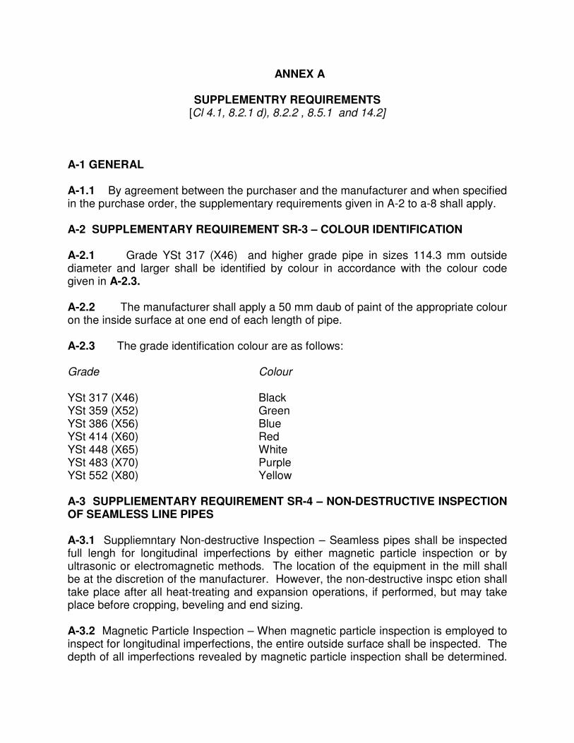
ANNEX A
SUPPLEMENTRY REQUIREMENTS [Cl 4.1, 8.2.1 d), 8.2.2 , 8.5.1 and 14.2]
A-1 GENERAL
A-1.1 By agreement between the purchaser and the manufacturer and when specified in the purchase order, the supplementary requirements given in A-2 to a-8 shall apply. A-2 SUPPLEMENTARY REQUIREMENT SR-3 – COLOUR IDENTIFICATION A-2.1 Grade YSt 317 (X46) and higher grade pipe in sizes 114.3 mm outside diameter and larger shall be identified by colour in accordance with the colour code given in A-2.3. A-2.2 The manufacturer shall apply a 50 mm daub of paint of the appropriate colour on the inside surface at one end of each length of pipe. A-2.3 The grade identification colour are as follows: Grade Colour YSt 317 (X46) Black YSt 359 (X52) Green YSt 386 (X56) Blue YSt 414 (X60) Red YSt 448 (X65) White YSt 483 (X70) Purple YSt 552 (X80) Yellow A-3 SUPPLIEMENTARY REQUIREMENT SR-4 – NON-DESTRUCTIVE INSPECTION OF SEAMLESS LINE PIPES A-3.1 Suppliemntary Non-destructive Inspection – Seamless pipes shall be inspected full lengh for longitudinal imperfections by either magnetic particle inspection or by ultrasonic or electromagnetic methods. The location of the equipment in the mill shall be at the discretion of the manufacturer. However, the non-destructive inspc etion shall take place after all heat-treating and expansion operations, if performed, but may take place before cropping, beveling and end sizing. A-3.2 Magnetic Particle Inspection – When magnetic particle inspection is employed to inspect for longitudinal imperfections, the entire outside surface shall be inspected. The depth of all imperfections revealed by magnetic particle inspection shall be determined.
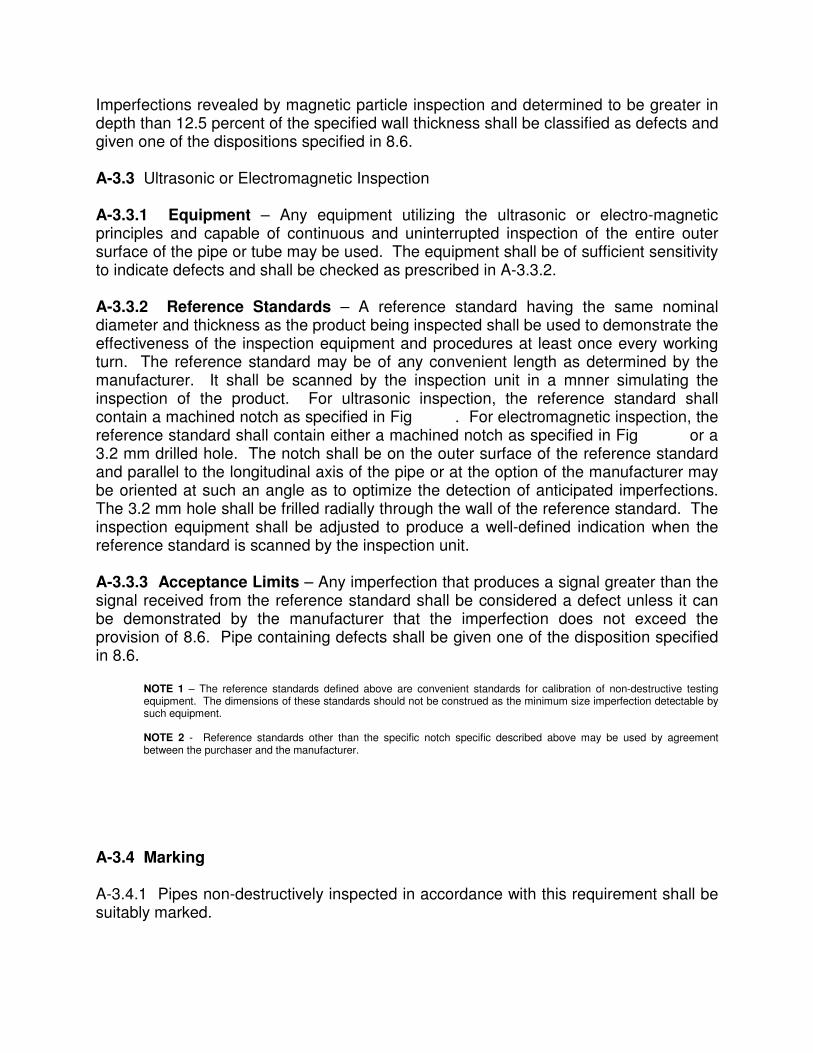
Imperfections revealed by magnetic particle inspection and determined to be greater in depth than 12.5 percent of the specified wall thickness shall be classified as defects and given one of the dispositions specified in 8.6. A-3.3 Ultrasonic or Electromagnetic Inspection A-3.3.1 Equipment – Any equipment utilizing the ultrasonic or electro-magnetic principles and capable of continuous and uninterrupted inspection of the entire outer surface of the pipe or tube may be used. The equipment shall be of sufficient sensitivity to indicate defects and shall be checked as prescribed in A-3.3.2. A-3.3.2 Reference Standards – A reference standard having the same nominal diameter and thickness as the product being inspected shall be used to demonstrate the effectiveness of the inspection equipment and procedures at least once every working turn. The reference standard may be of any convenient length as determined by the manufacturer. It shall be scanned by the inspection unit in a mnner simulating the inspection of the product. For ultrasonic inspection, the reference standard shall contain a machined notch as specified in Fig . For electromagnetic inspection, the reference standard shall contain either a machined notch as specified in Fig or a 3.2 mm drilled hole. The notch shall be on the outer surface of the reference standard and parallel to the longitudinal axis of the pipe or at the option of the manufacturer may be oriented at such an angle as to optimize the detection of anticipated imperfections. The 3.2 mm hole shall be frilled radially through the wall of the reference standard. The inspection equipment shall be adjusted to produce a well-defined indication when the reference standard is scanned by the inspection unit. A-3.3.3 Acceptance Limits – Any imperfection that produces a signal greater than the signal received from the reference standard shall be considered a defect unless it can be demonstrated by the manufacturer that the imperfection does not exceed the provision of 8.6. Pipe containing defects shall be given one of the disposition specified in 8.6.
NOTE 1 – The reference standards defined above are convenient standards for calibration of non-destructive testing equipment. The dimensions of these standards should not be construed as the minimum size imperfection detectable by such equipment.
NOTE 2 - Reference standards other than the specific notch specific described above may be used by agreement between the purchaser and the manufacturer.
A-3.4 Marking A-3.4.1 Pipes non-destructively inspected in accordance with this requirement shall be suitably marked.
NOTE 1- Depth of notch, h, shall be 12.5 percent of the nominal wall thickness of the pupe being inpected but not less than 0.30 mm.
NOTE 2 - For ultrasonic and eddy current, the length of notch at full depth, L, shall be at least twice the width of the scanning head.
NOTE 3 - For diverted flux, the length of notch shall be as required by the equipment design to provide a reproducible signal when the reference standard is passed through the equipment shall be required to ensure reproducibility.
A-4 SUPPLEMENTARY REQUIREMENT SR-5 – FRACTURE TOUGHNESS TESTING (CHARPY V-NOTCH) FOR PIPES 114.3 mm DIAMETER OR LARGER A-4.1 Charpy V-notch tests shall be conducted in accordance with IS 1757 except as modified herein. Either or both toughness criteria (see A-4 Shear Area or A-5 Absorbed Energy) may be specified under this supplementary requirement. A-4.2 Except for flattening specimens, the requirements of this supplementary requirements are limited to pipe sizes and wall thicknesses from which a half size specimen may be secured. The specimens shall be oriented circumferentially from a location of 900 from the weld with the axis of the notch oriented through the pipe wall thickness as shown in Fig. 16. A-4.3 Except as limited by item c) below, any of the following Charpy V-notch specimens are permissible by agreement between the purchaser and manufacturer.
a) Full-size specimen — Full-size specimens (10 mm by 10 mm) with or without tapered 3 ends may be used (see Fig. 17).
b) Subsize specimens – The largest possible subsize specimen (see Table A-1) with or without tapered ends may be used. All dimensions other than specimen width are the same as the full-size specimen. Selecting subsize specimens for pipe whose size permits full-size specimens is also permissible by agreement between the purchaser and the manufacturer.
c) Flattened specimens – When because of combinations of diameter and wall thickness the use of 2/3 size tapered end specimens is not practicable (see Table A-1), flattened specimens, ½ size conventional specimens, or ½ size tapered end specimens shall be used by agreement between the purchaser and the manufacturer. Flattened specimens may be flattened at room temperature in the same manner as transverse tensile strip specimens are prepared. Hot flattening, artificial aging, or heat tretment of flattened specimens is not permitted. The flattened specimens shall have OD and ID surfaces machined no more than sufficient to make them parallel, or the surfaces shall be wire brushed ior cleaned without machining. The specimen width shall essentially represent the full wall thickness of the pipe. All dimensions other than specimen width shall be the same as full-size specimens. The user is cautioned that results of flattened specimens and full-size or subsize specimens may not be correlated or directly compared with one another.

A-4.5 If any Charpy V-notch test result for a heat of pipe fails to conform to the applicable requirements given in SR 5A or SR 5.B , the manufacturer may elect to heat treat the heat of pipe in accordance with the requirements of 8.5.2, considerate to be a new heat, test it in accordance with the requirements of Cl 8.5.1, SR 5 and SR 6 that are applicable requirements of this specification. After one reprocessing heat treatment, any additional reprocessing heat treatment shall be subject to agreement with the purchaser. For non-heat treated pipe, any reprocessed heat treatment shall be subject to agreement with the purchaser. For heat treated pipe, any reprocessing with a different type of heat treatment (see 5.7) shall be subject to agreement with the purchaser. A-5 SUPPLEMENTARY REQUIREMENT SR-5A – SHEAR AREA A-5.1 Three transverse specimen shall betaken from one length of pipe from each heat supplied on the order. The specimens shall be tested at 100C or at a lower temperature as specified by the purchaser. The average shear value of the fracture appearance of the three specimens shall not be less than 60 percent, and the all-heat average for each order per diamenter size and grade shall not be less than 80 percent. A-5.2 If the average of the three specimen from one heat does not meet the requirement of 60 percent shear, the manufacturer may elect to repeat the tests on specimens cut from two additional lengths of pipe from the same heat. If such specimens conform to the specified requirements, all the lengths in the heat shall be accepted except the length initially selected for test. If any of the retest specimens fail topass this specified retest requirement, the manufacturer may elect to test specimens cut from the individual lengths remaining in the heat. A-5.3 The average shear value for a heat shall be the average of the original three specimens if the average is 60 percent or more; the combined average of the retest specimens , provided the average of each group of three specimens is 60 percent or more; or, in the event individual lengths are tested, the combined average of all groups of three specimens that meet 60 percent. The all-heat average value is the combined average of the average shear value for each of the heats supplied for the order item. A-5.4 If the all-heat average of the order does not meet the requirement of 80 percent shear, the manufacturer shall be responsible for replacement of such heats as may be necessary to bring the average shear area up to 80 percent. A-5.5 Alternatively, the manufacturer may elect to test two or more additional lengths from one or more of the heats. In determining the new heat average, the original test values may be discarded if the pipe length represented is rejected or the three or more individual values are averaged. In any case, the new test values shall be incorporated into the value for the heat.

A-5.6 Specimens showing material defects or defective preparation, whether observed before or after breaking, may be discarded and replacements shall be considered as original specimens. A-5 7 Marking – Pipes tested in accordance with the shear area requirements of this supplementary requirement shall be marked to indicate the type of test, the test temperature, and if flattened specimens are used, the type of specimen. Temperatures below zero shall be preceded by the letter M Example at 00C: SR5A--00C Example of flattened specimen at –400C: SR5AF-M400C A-6 SUPPLEMENTARY REQUIREMENT SR-5B – ABSORBED ENERGY
A-6.1 The fracture toughness of the pipe shall be determined using Charpy V-notch impact test specimens in accordance with IS 1757:1988 except as modified herein and the requirements specified in A-4.1, except the test frequency shall be as indicated in A-5.2. The purchaser shall specify, in whole numbers both the test temperature and the minimum average absorbed energy for full-size specimens. Specimens used for shear area determination according to A-4 may be additionally used for the determination of absorbed energy. A-6.2 Three transverse specimens representing one test shall be taken one length of pipe from each inspection per heat produced. An inspection lot shall consist of pipe that is made to the same size and same specified wall thickness by the same process and under the same manufacturing conditions. A-6.3 For acceptance, the average absorbed energy of the three individual specimens from a length shall not be less than the full-size value specified by the purchaser. In addition, the lowest individual reading of the three specimens shall not be less than 75 percent of the specified value. When sub-size specimens are used, the individual readings and the average of the three readings are divided by the ratio of the specimen thickness tested to the full-size specimen thickness and compared with the full-size acceptance criteria. When flattened specimens are used, each of the three individual impact energy readings shall be multiplied by 10 and divided by the actual measured specimen width, in millimeter. These results, and the average of the three results, shall meet the specified absorbed energy acceptance criteria for full-size specimens. A-6.4 Specimens showing material defects or defective preparation, whether observed before or after breaking, may be discarded and replacements shall be considered original specimens. In the event a set of test specimens fails to meet the acceptance criteria, the manufacturer may elect to replace the lot of material involved or alternatively to test two more lengths from the same lot. If both of the new tests meet the acceptance criteria, then all pipe in the lot with the exception of the original selected length shall be considered to meet the requirement . Failure of either of the two additional tests shall require testing of each length in the lot for acceptance.

A-6.5 Pipe complying with absorbed energy requirements of this supplementary requirement shall be marked to indicate the type of test, the specified [full-size] minimum average absorbed energy, the test temperature, and, if flattened specimens are used, the type of specimen. Temperatures below zero shall be preceded by the letter M, and absorbed energyspecified in joules shall be followed by the letter J.
Example for 20 ft-lb at 00C: SR5B-20-0C Example of flattened specimens for 20 ft-lb at -400F Example of flattened specimen For both SR5A and SR5B for 27 joules at 00C: SR5ABF-27J-0C A-7 SUPPLEMENTARY REQUIREMENT SR-6 –DROP WEIGHT TEAR TESTING ON WELDED PIPE 508.0 MM OR LARGER, GRADE YSt 359 (X52) OR HIGHER
A-7.1 Fracture toughness of pipe 508.0 mm in diameter and larger, Grade YSt 359 and higher, shall be determined by the manufacturer using drop weight tear tests in accordance with the following requirements.
A-7.2 Two transverse specimens shall be taken from one length of pipe from each heat supplied on the order. The specimens shall be oriented circumferentially from a location of 900 from the weld with the axis of the notch oriented through the pipe wall thickness as shown in Fig. 16. The specimens shall be tested at 100C or at a lower temperature as specified by the purchaser. A-7.3 The test specimens, testing procedure and rating of the specimens shall be in accordance with API RP 5L 3. Recommended practice for conducting drop weight tear test on line pipe. The type of notch (pressed or chevron) shall be selected by the agreement between the manufacturer and purchaser. A-7.4 At least 80 percent of the heats shall exhibit a fracture appearance shear area of 40 percent or more for the specified test temperature. Note – Due to manufacturing difficulties encountered with thicker materials, pipe producer may not be able to offer pipes in all grades that meet this requirement. A-7.5 In the event of the average value of the two specimens from the length selected to represent the heat being less than 40 percent, the manufacturer may elect to establish the heat average by testing two specimens from each of two or more additional length of pipe in the heat. In establishing the new heat average, the manufacturer may elect to employ the combined average of the three or more tests, or to discard the result of the first test, reject the pipe from which it was taken, and employ
the combined average of the two or more additional test. Alternatively, the manufacturer may elect to test all the pipes in the heat, in which case 80 percent or more of the lengths tested and applied to the order must exhibit an average of 40 percent or more shear. A-7.6 Specimens showing materials defects or defectives preparation, whether observed before or after breaking, may be discarded and replacement shall be considered as original specimens.
A-7.7 The manufacturer shall be responsible for replacement of such heats as may be necessary to meet the above requirements. Example for chevron notch at 00C: SR6C- A-7.8 Marking – Pipe tested in accordance with this supplementary requirement shall be marked to indicate the type of test, the type of notch, and the test temperature. The temperature below zero shall be preceded by the letter M. Example for chevron notch at 00C: SR6C-0C Example for pressed notch at –100C: SR6P-M10C A-8 SUPPLEMENTARY REQUIREMENT SR-7 –THROUGH THE FLOW LINE (TFL) PIPE A-8.1 General – TFL pipe shall comply with all requirements of this specification and the additional requirements specified hereafter. A-8.2 Dimension and Grades – TFL pipe shall be seamless or longitudinal seam pipe in the outside diameters, wall thickness and grades as shown in Table A-2 A-8.3 Length – Unless otherwise specified, TFL pipe shall be furnished only in double random length with no jointers (girth welds). A-8.4 Drift Tests – Each length of TFL pipe shall be tested throughout its entire length with a cylindrical drift mandrel conforming to the requirements listed below. The leading edge of the drift mandrel shall be rounded to permit easy entry into the pipe. The drift mandrel shall pass freely through the pipe with a reasonable exerted force equivalent to the weight of the mandrel being used for the test. Pipe shall not be rejected until it has been drift tested when it is free of all foreign matter and properly supported to prevent sagging. ------------------------------------------------------------------------------------------------------------ Drift Mandrel Size -------------------------------------------------------------------------------- Length Diameter, Min ------------------------------------------------------------------------------- Size, mm mm mm ------------------------------------------------------------------------------------------------------------ smaller than 88.9 1066 d - 2.4

88.9 and greater 1066 d - 3.2 where d is the internal diameter of the pipe. A-8.5 Hydrostatic Tests – TFL pipe shall be hydro statically tested in accordance with Cl 13 except that the minimum test pressures shall be as shown in Table A-2. These test pressures in Table A-2 represent the lesser of 68900 kPa and the pressure calculated with the equation in given in 13.2, using a fibre stress equal to 80 percent of the specified minimum yield strength. A-8.6 Marking – TFL pipe manufactured in accordance with this supplementary requirement shall be marked with the letters TFL in addition to the marking required in Cl19.
A-9 NON-DESTRUCTIVE INSPECTION OF WELDS IN ELECTRIC WELDED PIPE AND LASER WELDED PIPE
A-9.1 Supplementary Non-destructive Inspection – The weld seam in electric pipe and laser welded pipe shall be inspected full length in accordance with the applicable methods specified in Table 14 for the entire thickness. The non-destructive inspection shall take place after all heat treating, hydrostatic testing, expansion and rotary straightening operations. If performed, but may take place before cropping, beveling and sizing of pipe. A-10 TEST CERTIFICATE AND TRACEABILITY FOR LINE PIPE A- The manufacturer shallprovide thefollowing data as applicable, for each order item for which this supplementary requirement isspecified on the purchase order. |The manufacturer’s certificate ofcomplianceshall statethe API specification and date ofrevision to which pipe was manufactured. A material Test Report,Certificate of Complaince, or similar document printed from orused in electronic form from an electronic date interchange (EDI) transmission shall be regarded as having the same validity as a couterpart printed in the manufacturer’s facility. The content of the EDI transmitted document must meet the requirements ofthis specification and conform to any existing EDI agreement between the purchaser and the manufacturer.
a) Specified outside diameter, specified wall thickness, grade, process of manufacturte and type of heat treatment.
b) Chemical analysis (heat, product and recheck) showing the weight percent of all elements whose limitsor reporting requirements are set in this specification; for PSL 2 pipe, carbon equivalent and applicable maximum allowable value. If order is for by-agreement high carbon equivalent pipe.’ That designation shall be included.

c) Test data for all tensile tests required by this specification, including yeidlstrength,ultimate tensile strength and elongation. The type, size and orientation of specimens shall be shown. d) Fracture toughness test results(including test type and criteria and the siz\e, location and orientation of the specimen) where such testing is required. e) Minimum hydrostatic test pressure and duration. f) For weld pipe for which nondestructive inspection of the weld seam is required by this specification, the method of nondestructive inspection employed (radiological, ultrasonic, electromagnetic and/or magnetic particle) and the type and the size of all imageindicators and reference indicators used. g) For seamless pipe forwhich nondestructive inspection (SR4) is required, the method of inspection employed(ultrasonic, electromagnetic or magnetic particle) and the type and size of the reference standard used. h) For electricwelded pipeand laserwelded pipe, the minimum temperature for heat treatment of the weld seam. Where such heat treatment is not performed, the words No seam Heat Treatment’ shall be started on the certificate Results of any supplementaqql testing required by the purchaser.
ANNEX D REPAIR OF DEFECTS BY WELDING
( Cl 11.13 , 12 b)and 16.1 )
D-1 TYPES OF PIPE D-1.1 Seamless Pipe and Parent Metal of welded Pipe – For PSL 1 pipe, the repair of defects in seamless pipe and parent metal of welded pipe is permissible except 2when the depth of defect exceed one-third of the specified wall thickness of the pipe and the length of that portion of the defect, in which the depth exceeds 12.5 percent , is more than 25 percent of the specified outside diameter of the pipe, or when more than one repair is required in any length equivalent to ten times the specified outside diameter of the pipe. Repair shall be made in accordance with D-2. Repair welds shall be inspected by the magnetic particle method, liquid penetration or by other NDT methods as agreed between purchaser and the manufacturer. For PSL 2 pipe, the repair of defects in seamless pipe or in parent metal of welded pipe is not permitted (see 5.6).
D-1.2 Weld Seam or Welded Pipe – Defects in filler metal weld may be repaired at the discretion of the manufacturer in accordance with D-3. For PSL 1 pipe weld seams made without filler metal (electric and laser welds) may be repaired by welding only by agreement between the purchaser and the manufacturer. Such repairs shall be in accordance with D-4. For PSL 2 pipe, weld seams made without filler metal shall not be repaired by welding. D-1.3 Heat Treated Pipe – When heat treated pipe has been repaired by welding, the subsequent reheat treatment shall be as agreed to between the manufacturer and the purchaser, based on the effect of the repair on the structure and properties of heat treated pipe. D-2 PROCEDURE FOR REPAIR BY WELDING OF SEAMLESS PIPE AND PARENT METAL OF WELDED PIPE (PSL 1 ONLY) The repair of defects in seamless pipe and parent metal of welded pipe shall conform to the following requirements. Conformance to the repair procedure is subject to approval 0of the purchaser’s inspector. D-2.1 The defect shall be removed completely by chipping or grinding or both and the resultant cavity shall be thoroughly cleaned and shall be inspected by magnetic particles methods, before welding, to ensure complete removal of the defect. D-2.2 The minimum length of repair weld shall be 50.8 mm. where the orientation of the defect permits, the repair weld shall be placed in the circumferential direction. D-2.3 The weld shall be made either by automatic submerged-arc welding, gas metal-arc welding, or manual shielded metal-arc welding using low-hydrogen electrodes. The metal temperature in the area to be repaired shall be a minimum of 100C (500F). The welding procedure and operator shall be qualified in accordance with Annex E . D-2.4 The repair weld shall be ground to merge smoothly into original contour of the pipe. D-2.5 Repaired pipe shall be hydrostatically tested after repairing in accordance with Cl 13 D-3 PROCEDURE FOR REPAIR OF WEELD SEAMS OF SUBMERGED ARC AND GAS METAL ARC WELDED PIPE The repair of defects in the weld seam of submerged arc and gas metal arc welded pipe shall conform to the following requirements. Conformance is subject to approval of purchaser’s inspector. D-3.1 The defect shall be completely removed and the cavity shall be thoroughly cleaned. For PSL 2 pipe, the rim of the resultant cavity shall not extend into the paremt metal by more

than 3.2 mm as measured along the pipe surface, perpendicular to the weld (see Fig C/B-1). Where multiple pass repairs are used, the size of the cavity shall be sufficiently large 50.8 mm to avoid coincidence of starts and stops of individual passes. D-3.2 Each repair weld shall be at least 50.8 mm in length. The repair weld shall be made either by automatic submerged arc welding, gas metal arc welding, or manual shielded metal arc welding using low-hydrogen electrodes. The welding procedure and operator shall be qualified in accordance with Annex E. D-3.3 Each length repaired pipe shall be hydrostatically tested in accordance with Clause 13 D-3.4 Repair of weld seamof SAW pipe is not permittedwithin 200 mm from the bevel ends. D-4 PROCEDURE FOR REPAIR OF WEELD SEAMS OF ELECTRIC AND LASER WELDED PIPE The repair welding of the weld seam of electric and laser shall conform to the following requirements and shall include the weld zone, which is defined for the purpose of repair as 12.7 mm on each side of the fusion line. Conformance to the repair procedure is subject to approval of purchaser’s inspector. D-4.1 The weld zone defect shall be removed completely by chipping or grinding or both and the resultant cavity shall be thoroughly cleaned. D-4.2 The minimum length of repair weld shall be 50.8 mm and individual weld repairs shall be separated by at least 3 m. D-4.3 The repair weld shall be made either by automatic submerged-arc welding, gas metal-arc welding, or manual shielded metal-arc welding using low-hydrogen electrodes. The metal temperature in the area to be repaired shall be a minimum of 100C (500F). The welding procedure and operator shall be qualified in accordance with Annex E. D-4.4 When a repair weld is made through the full wall thickness, it shall include weld passes made from both the inner diameter (ID) and outer diameter (OD) of the pipe. Starts and stop of the ID and OD repair welds shall not coincide. D-4.5 the repair shall be ground to merge smoothly into the original contour of the pipe and shall have a maximum crown of 1.52 mm. D-4.6 Repaired pipe shall be hydrostatically tested after repairing in accordance with Clause 13

49
ANNEX E ( Cl D-2.3, D-3.2 and D-4.3 )
REPAIR-WELDING PROCEDURE AND WELDER PERFORMANCE TESTS
E-1 GENERAL E-1.1 All manual and semi-automatic submerged arc, gas shielded arc and metallic arc repair welds using coated electrodes shall be made according to a tested procedure and by a repair welder tested in a flat position as specified in E-2 and E-3. When the base metal temperature of the material to be repaired welded is below 100C, submerge arc, gas shielded arc or manual metallic arc methods with low hydrogen electrodes shall be used. The manufacturer shall maintain a record of the procedure and performance test results. E-2 REPAIR-WELDING PROCEDURE TEST E-2.1 Repair-welding procedure tests shall be carried out on two specimens of every grade and on material which is on the high side of the chemistry specification and which is at least as the pipe on which welds are to be made. These tests shall be carried out at a temperature at or below the lowest temperature at which repair-welds are made. E-2.2 Transverse Tensile Test – The transverse tensile test specimen shown in Fig 18(a) shall be approximately 38 mm wide and shall have the transverse metallic arc butt-weld perpendicular to the longitudinal axis at the center of the test specimen. The weld reinforcement shall be removed from both faces. The ultimate tensile strength shall at least be equal to the minimum specified for the grade. E-2.3 Longitudinal Tensile-Elongation Test – The longitudinal tensile elongation test specimen shall conform to Fig. 18(b). The weld shall be made in a groove as shown. The elongation after complete rapture of the test specimen in tension shall at least be equal to the minimum elongation specified for the grade. E-2.4 Transverse Guided-Bend Test—the transverse guided-bend test shall conform to Fig. 18(c). The weld shall be made in a groove as shown. The specimen shall be placed on the die with the weld at mid-span, and shall be bent through approximately 1800C in a jig substantially in accordance with Fig. 18( c) with the exposed surface of the weld in tension. The bend test shall be acceptable if no crack or any other defect exceeding 3 mm in any direction develops in the weld metal or between the weld and the pipe metal after bending. Cracks which originate along the edges of the specimen during testing and which are less than 6 mm, measured in any direction, shall not be considered. The specimen cracks or fractures during bending and the exposed surface shows complete penetration and fusion throughout the entire thickness of the weld specimen, there shall not be

50
more than six gas pockets for an area of 645 mm2 with the largest dimension not exceeding 1.6 mm and no slag inclusion greater thqn 0.8 mm in depth or 3 mm in width and separated by at least 12.7 mm of sound metal. If necessary, the specimen shall be broken apart to permit examination of the fracture. E-3 NICK-BREAK TEST E-3.1 The specimen shall conform to Fig. 19. The weld shall be made in a groove as shown. The specimen shall be hacksaw notched from both edges to the center of the weld and shall be broken by pulling or by hammer blows at the center or one end. The test shall be accepted if the exposed surface shows not more than: a) One gas pocket for nominal wall thickness of 6.3 mm and less; b) Two gas pockets for nominal wall thickness of 12.7 mm or less but greater than 6.3 mm; and c) Three gas pockets for nominal wall thickness greater than 12.7 mm. E-4 REPAIR-WELDER PERFORMANCE TESTS E-4.1 Repair-welder performance tests are required on two specimens from each test of every grade, except that a welder qualified on one grade is also qualified for any lower grade. If either of the two specimens fails to conform to the requirements specified, four retests shall be required, if made immediately or two retests shall be required if the welder takes further instructions in the practice before making a retest. All retests shall conform to the requirements specified. Further performance tests are required at an interval of 1 year, Min; and also if the repair-welder is not engaged in the repair-welding testing procedure for a period of three months or more, or if there is some specific reason to question his ability. Both the following tests shall be made: a) Transverse guided-bend test – as specified in E-2.4, and b) Nick-break test – as specified in E-3

51

52
ANNEX F (Cl 14.1.3)
NON-DESTRUCTIVE INSPECTION OF WELDS IN ELECTRIC WELDED PIPE
AND LASER WELDED PIPE F-1 SUPPLEMENTARY NON-DESTRUCTIVE INSPECTION The weld seam in electric pipe and laser welded pipe shall be inspected full length in accordance with the applicable methods specified in Table 14 for the entire thickness. The non-destructive inspection shall take place after all heat treating, hydrostatic testing, expansion and rotary straightening operations. If performed, but may take place before cropping, beveling and sizing of pipe. F-2 MAGNETIC PARTICLE INSPECTION F-2.1 When magnetic particle inspection is employed to inspect for longitudinal imperfections, the entire outside surface shall be inspected. The depth of all imperfections revealed by magnetic particle inspection shall be determined and when found to be greater than 12.5 percent of the specified wall thickness shall be classified as defects and given one of the disposition specified in 12. F-3 RESIDUAL MAGNETISM MEASUREMENT REQUIREMENT F-3.1 The requirements of this paragraph apply only to testing within the pipe manufacturing facility. Measurements of residual magnetism on pipe,subsequent to leaving the pipe manufacturing facility, may be affected by procedures and conditions imposed on the pipe during and after shipment. a) The longitudinal magnetic field shall be measured on plain-end pipe of sizes 65/8 and larger, and al smaller plain end pipe that is inspected full length by magnetic methods or is handled by magnetic equipment prior to loading. Such measurements shall be taken on the root face or square cut face of finished plain-end pipe. b) Measurements shall be made using a Hal-effect gaussmeter or other type of calibrated However, in case of dispute, measurements made with a Hal-effect gaussmeter shall govern. The gaussmeter shall be operated in accordance with written instructions demonstrated to produce accurate results. c) Measurements shall be made on each end of a pipe to be selected at lease once per 4 hours per operating shift.

53
d) Pipe magnetism shall be measured subsequent to any inspection that utilizes a magnetic field, prior tom loading for shipment from the manufacturer’s facility. For pipe handled with electromagnetic equipment after measurement of magnetism. Such handling shall be performed in a manner demonstrated not to cause residual magnetism in excess of the levels stipulated in item e. e) As a minimum, four readings shall be taken approximately 90O apart around the circumference of each end of the pipe. The average of the four readings shall not exceed 30 gauss (3.0 mT). And no one reading shall exceed 35 gauss (3.5 mT) when measured with a Hall-effect gaussmeter, or equivalent values when measur3d with other types of instruments. f) Any pipe that does not meet the requirements of item e), shall be considered defective. In addition, all pipe produced between the defective pipe and the last acceptable pipe prlduction sequence is documented, pipe may be measured in reverse sequence is documented, pikpe may be measured in reverse sequence beginning with the pipe produced prior to the defective pipe until at least three connectively produced. Pipes meet the requirements: pipe produced prior to the three acceptable pipes need not be measured. Pipe produced after the defective pipe shall be measured individually until at least three consecutive pipes meet the requirements. Measurements made on pipe in stacks or bundles are not considered valid. All defective pipe shall be demagnetized full length, and remeasured until at least three consecutive pipes meet the requirements. F-4 ULTRASONIC OR ELECTROMAGNETIC INSPECTION F-4.1 Equipment and Reference Standards --The ultrasonic or electromagnetic inspection equipment requirements are given in F-3, and the reference indicator requirements are given in Table 25. Details of the specific techniques such as method, reference standards, transducer properties and sensitivity shall be agreed upon between the purchaser and the manufacturer for the implementation of this supplementary requirement. F-4.2 Equipment – Any equipment utilizing the ultrasonic or electromagnetic principles and capable of continuous and uninterrupted inspection of the entire outer and, or inner surface of the pipe may be used. The equipment shall be standardized with an applicablestandard as described in F 4.3 at least once per operating shift to demonstrateits effectiveness and the inspection procedures. The equipment shall be adjusted to produce well-defined indications when the reference standard is inspected in accordance with F 4.3.

54
For welded pipe, the equipment shall be capable of inspecting through the entire thickness of the weld seam as follows|:
a) For electric welded pipe and laser welded pipe, the weld line plus 1.6 mm of adjacent parent metal on each side of the weld line.
b) For pipe welded with filler metal, the weld metal plus 1.6mm of adjacent metal on each side of weld metal.
F-4.3 Reference Standards – Each reference standard shall have its outside diameter and wall thickness within the tolerance specified for the production pipe to be inspected and may be of any convenient length as determined by the manufacturer. Reference standards shall contain one or more machined notches or one or more radially drilled holes as specified in Table 25. Reference indicators shall be separated by a distance sufficient to produce separate and distinguishable signals. The equipment shall be adjusted to produce well-defined indications when the reference standard is inspected by the inspection unit. Depth of notch, h Shall be 12.5 percent of the nominal wall thickness of the pipe being inspected, but not less than 0.30 mm . For ultrasonic and eddy current the length of notch at full depth, L, shall be at least twice the width of the scanning head. For diverted flux the length of notch shall be as required by the equipment design to provide a reproducible signal when the reference standard is passed through the equipment at the inspection line speed for the pipe being inspected. Three passes through the equipment shall be required to insure reproducibility (see Fig.F- 1) F-4.4 Acceptance Limits – Table 26 gives the height of acceptance limit signals produced by reference indicators. Any imperfection that produces a signal greater than the signal received from the reference standard shall be considered a defect unless it can be demonstrated by the manufacturer that the imperfection that the imperfection does not exceed the provision of 11. Pipe containing defects shall be given one of the dispositions specified in 12. F-5 MARKING F-5.1 Pipe non-destructively inspected in accordance with this requirement shall be suitably marked.

55
ANNEX G ( Cl 9.3.6 )
SPECIFICATION FOR WELDED JOINTER G-1 Method Welding of any type that uses deposited filter and is generally recognized as sound practice shall be permitted unless the purchaser specifies a particular method. Welding procedures, welders, and welding machine operators (hereafter called operators) shall be qualified in accordance with API Std 1104. Copies of the welding procedure specification and procedure qualification record shall be provided to the purchaser upon request. G-2 Workmanship The ends of the pipe to be welded together shall be prepared in accordance with the requirements of the procedure to be used. Pipe weld seams (straight, helical or skelp end) shall be staggered between 51 mm and 203 mm unless otherwise specified by the purchaser. The completed jointers shall be straight within the limits of 9.2.5 of this specification. Each weld shall have a substantially uniform cross section around the entire circumference of the pipe. At no point shall its crowned surface below the outside surface of the parent metal nor shall it rise above the parent metal by more than 3.2 mm if submerged-arc welded, or by more than 1.6 mm., if welded by another process. G-3 Marking Each jointer shall be marked using paint to identify the welder or operator. G-4 Nondestructive Testing The girth welds of jointers shall be 100percent radiographed in accordance with the procedure and standards of acceptability in API Std 1104 (see Note). Jointer welds failing to pass this radiographic testing may be repaired and re-radiographed in accordance with the procedures and acceptance criteria of API Std 1104. Radiographic images shall be traceable to the pipe identity. Note: see 9.2.6 for length requirements on jointers

56
ANNEX H
END LOAD COMPENSATION FOR HYDROSTATICTEST PRESSURESIN EXCESS OF 90% OFSPECIFIEDMINIMUM YIELD STRENGTH (NORMATIVE)
(By agreement between the purchaser and themanufacturer, the following method may be used to determine the hydrostatic test pressure). H – 1 As a measure to prevent distortion when testing at pressures equivalent to stresses in excess of 90% of specified minimum yield strength, the manufacturer may bv apply a calculation to compensateforthe forces applied to the pipe end that producea compressive longitudinalstress. The calculation in this appendix is based on Barlow’s equation (see 9.4.3) modified by a factor based on the Maximum Shear Theory (seenote).The calculation may be appliedonly when testing in excess of 90% of the specifiedminimum yield strength. In no case may the gage pressurefor testing be less than that calculated using Barlow’s equation at 90% of specified minimum yield strength. NOTE – The calculation isan approximation of the effective hoop stress (SE), which is practicalfor application under mill pipe testing conditions. Other calculations provide closer approximations of effective hoop stress but are complexand therefore impracticalfor application. H.2 The test pressure calculated shall be rounded to the nearest 100 kpa. H.3 The hydrostatic test pressure compensated for pipe end loading shall be calculated according to the following equation: U.S. Customary Unit Equation: PRAR SE - ------------- AP P1 = ---------------------- D A1 ---- - ---- 2t AP
SI Unit equation: PRAR SE - ------------- AP P1 = 1000 ---------------------- D A1 ---- - ---- 2t AP
where:

57
A1 = internal cross – sectional area of pipe, AP = corss-sectional area of pipe wall, AR = cross-sectional area of ram, mm2 A1 = hydrostatic test pressure in kPa AR = internal pressure on end-sealing ram,psi kPa
AE= effective hoop[ stress in Mpa equal toa percentaveof the specified minimum yield strength D = specified outsidediameter, (mm) t = specified wall thickness, (mm)
H.4 The above equation may be manipulated algebraically to provide calculation in other terms appropriate to the manufacturer’s testing facility. H.5 Appropriate techniques for the control of effective hoop stress based on measurements of internal pipe and ram pressures varyu according to hydrotester system design. The manufacturer shall provide a control technique appropriate to his installation.


![ASME B36[1].10M Welded and Seamless Wrought Steel Pipe](https://img.pdfslide.us/doc/110x75/55cf96a6550346d0338ce1fb/asme-b36110m-welded-and-seamless-wrought-steel-pipe.jpg)