Embed Size (px)
Citation preview
Linac Quad Field Linac Quad Field and Position and Position
StabilityStability
Chris AdolphsenSLAC
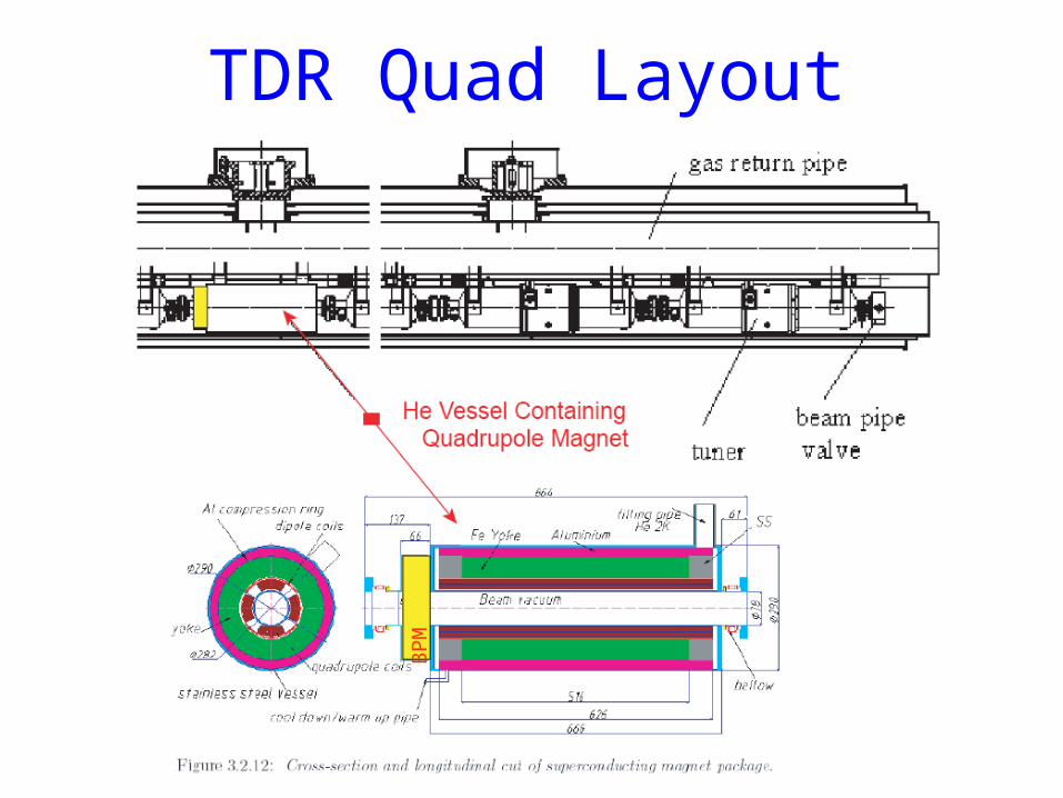
TDR Quad Layout
BP
M
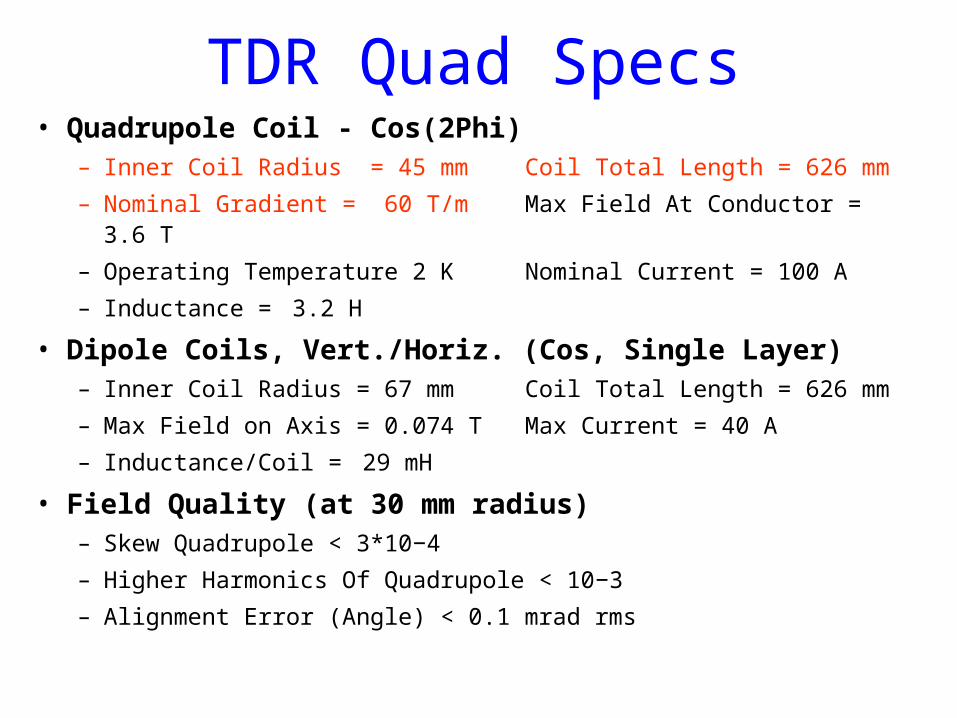
TDR Quad Specs• Quadrupole Coil - Cos(2Phi)
– Inner Coil Radius = 45 mm Coil Total Length = 626 mm
– Nominal Gradient = 60 T/m Max Field At Conductor = 3.6 T
– Operating Temperature 2 K Nominal Current = 100 A
– Inductance = 3.2 H
• Dipole Coils, Vert./Horiz. (Cos, Single Layer)– Inner Coil Radius = 67 mm Coil Total Length = 626 mm
– Max Field on Axis = 0.074 T Max Current = 40 A
– Inductance/Coil = 29 mH
• Field Quality (at 30 mm radius)– Skew Quadrupole < 3*10−4
– Higher Harmonics Of Quadrupole < 10−3
– Alignment Error (Angle) < 0.1 mrad rms
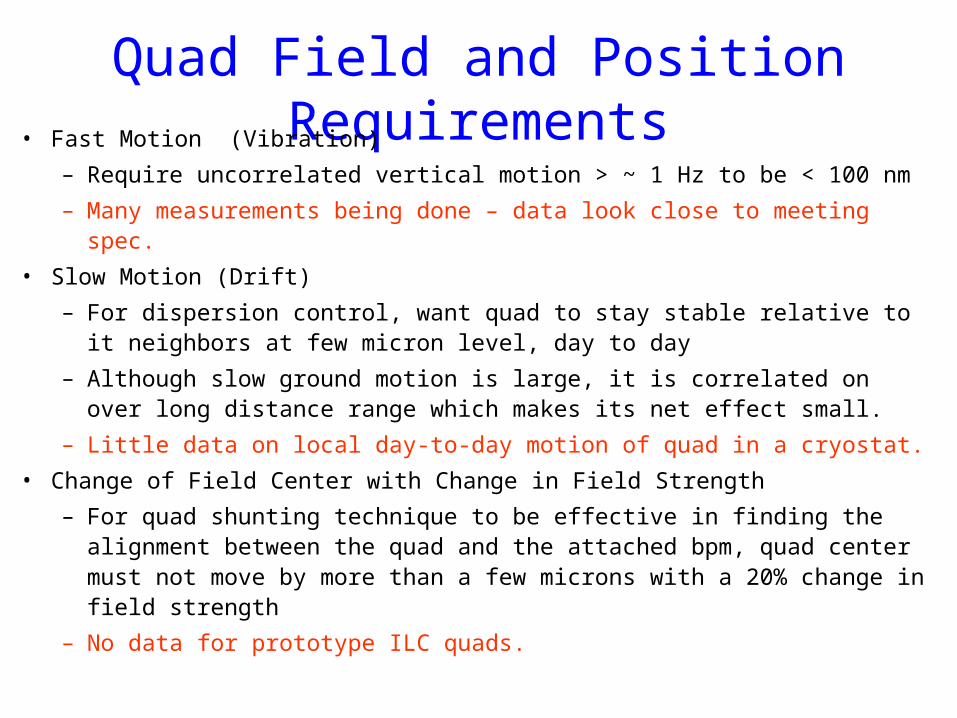
Quad Field and Position Requirements• Fast Motion (Vibration)
– Require uncorrelated vertical motion > ~ 1 Hz to be < 100 nm
– Many measurements being done – data look close to meeting spec.
• Slow Motion (Drift)
– For dispersion control, want quad to stay stable relative to it neighbors at few micron level, day to day
– Although slow ground motion is large, it is correlated on over long distance range which makes its net effect small.
– Little data on local day-to-day motion of quad in a cryostat.
• Change of Field Center with Change in Field Strength
– For quad shunting technique to be effective in finding the alignment between the quad and the attached bpm, quad center must not move by more than a few microns with a 20% change in field strength
– No data for prototype ILC quads.
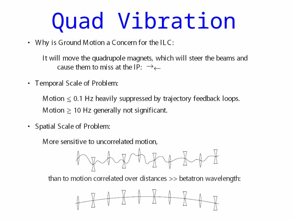
Quad Vibration
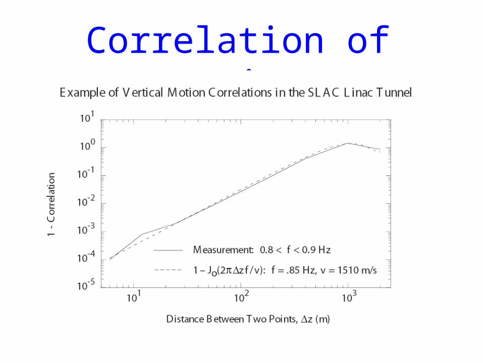
Correlation of Motion
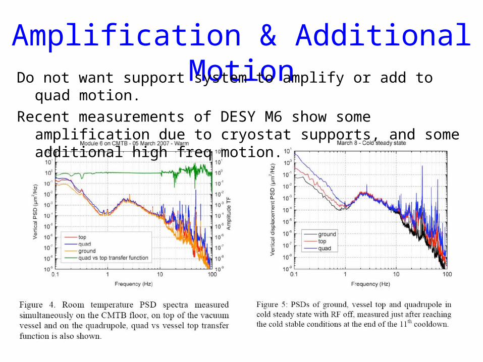
Amplification & Additional MotionDo not want support system to amplify or add to quad motion.
Recent measurements of DESY M6 show some amplification due to cryostat supports, and some additional high freq motion.
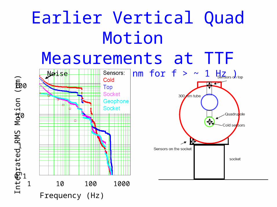
Earlier Vertical Quad Motion Measurements at TTF
(ILC Goal: < 100 nm for f > ~ 1 Hz )
1 10 100 1000
100
10
1
0.1
Frequency (Hz)
Inte
gra
ted
RM
S M
otio
n (n
m)
Noise
Long (> Minutes) Term Quad Motion
• One Concern is that He Gas Return pipe supports are intercepted by 40-80 K shield
• As heat load varies (rf on-off, beam on-off), the shield temperature may vary up to ~20 degK
• From Paolo Pierini (INFN)– A 1 K temperature variation results in a positional variation in the
range of 0.3 micron. Again, this is for a variation of the shield temperature, but a similar effect applies if the tunnel temperature changes (and this may explain also the measurements remembered by Carlo).
– Furthermore, fiberglass expansion coefficients depend on the orientation of the thermal gradient with respect to the primary fibers and on the fiber sizes, but we do not have any direct thermal expansion measurement (or thermal conductivity) data on our composite material, so I am relying on literature data.
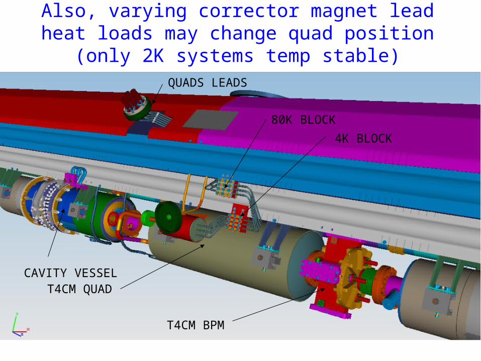
CAVITY VESSELT4CM QUAD
T4CM BPM
QUADS LEADS
80K BLOCK
4K BLOCK
Also, varying corrector magnet lead heat loads may change quad position (only 2K systems temp stable)
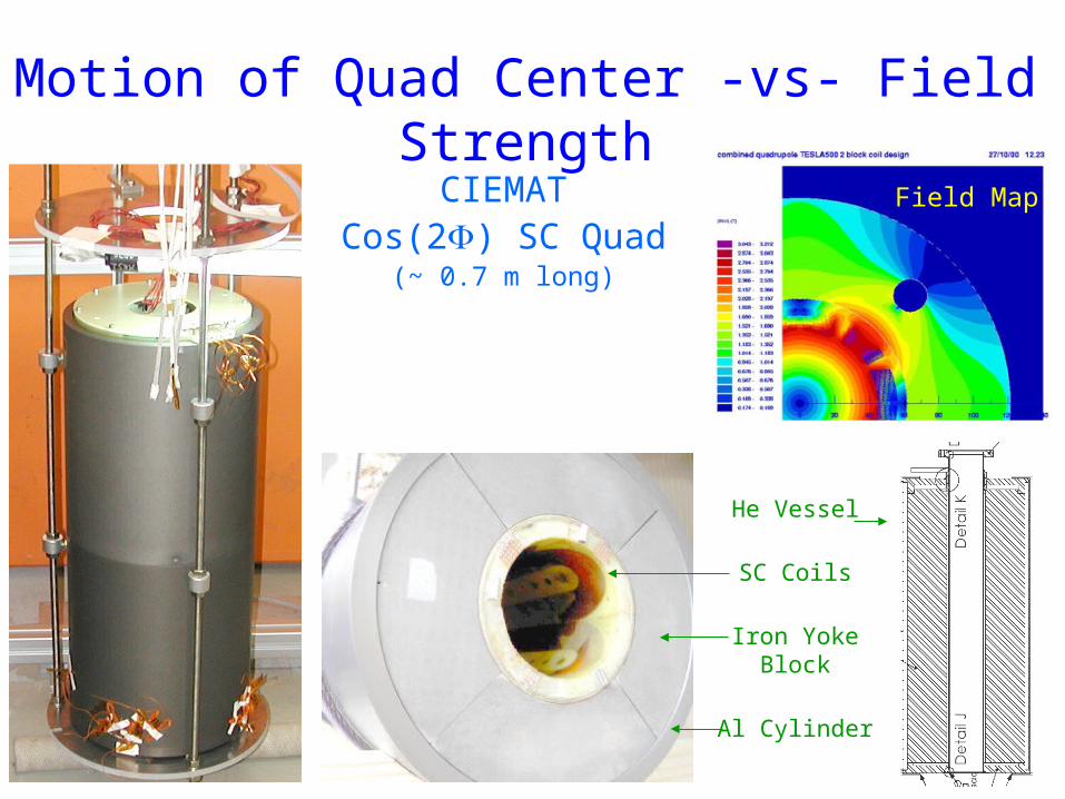
Field Map
Al Cylinder
Iron YokeBlock
SC Coils
He Vessel
Motion of Quad Center -vs- Field Strength
CIEMATCos(2) SC Quad
(~ 0.7 m long)
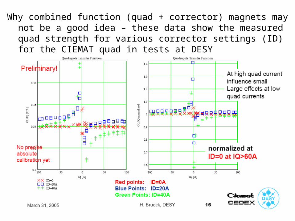
Why combined function (quad + corrector) magnets may not be a good idea – these data show the measured quad strength for various corrector settings (ID) for the CIEMAT quad in tests at DESY
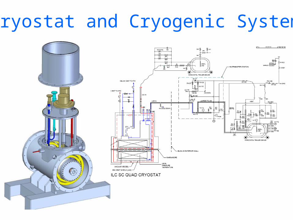
Cryostat and Cryogenic System
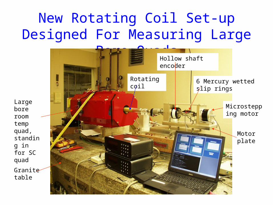
New Rotating Coil Set-up Designed For Measuring Large Bore Quads
Microstepping motor
6 Mercury wetted slip rings
Hollow shaft encoder
Granite table
Large bore room temp quad, standing in for SC quad
Motor plate
Rotating coil

Normal-Conducting Quad Center Stability Data Taken Over Five
Days
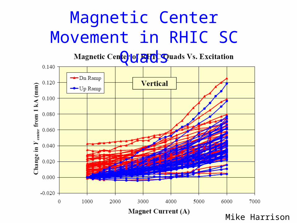
Mike Harrison
Magnetic Center Movement in RHIC SC Quads
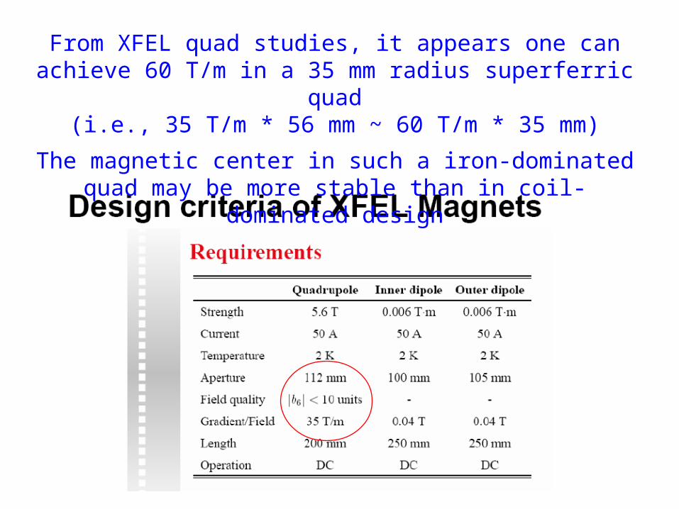
From XFEL quad studies, it appears one can achieve 60 T/m in a 35 mm radius superferric quad
(i.e., 35 T/m * 56 mm ~ 60 T/m * 35 mm)
The magnetic center in such a iron-dominated quad may be more stable than in coil-dominated design
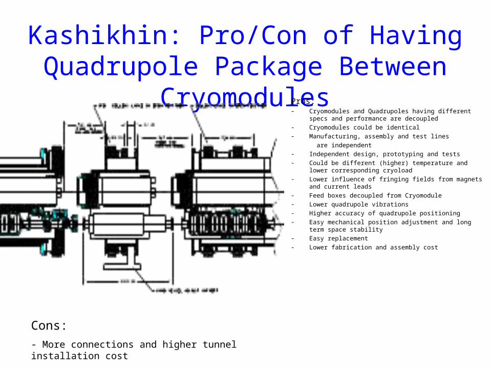
Kashikhin: Pro/Con of Having Quadrupole Package Between Cryomodules
Pros: - Cryomodules and Quadrupoles having different specs and
performance are decoupled- Cryomodules could be identical- Manufacturing, assembly and test lines
are independent- Independent design, prototyping and tests- Could be different (higher) temperature and lower corresponding
cryoload- Lower influence of fringing fields from magnets and current
leads- Feed boxes decoupled from Cryomodule- Lower quadrupole vibrations- Higher accuracy of quadrupole positioning- Easy mechanical position adjustment and long term space
stability- Easy replacement- Lower fabrication and assembly cost
Cons:
- More connections and higher tunnel installation cost
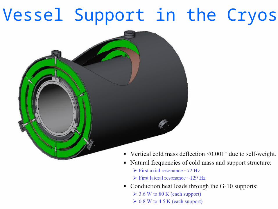
He Vessel Support in the Cryostat
Initial Quad and BPM Alignment
• To make the systematic BPM errors less than the required one micron
resolution, want beam centered in BPMs to the 100 micron level
• If the Quad/BPM are on movers (or cryomodules moveable)
– Only require that the BPM center be aligned to the quad magnetic center
to 100 microns – likely ‘bolt’ the two devices together
• If the Quad/BPM are not on movers (baseline) nor cryomodules
moveable
– Also want to quads to be aligned to 100 microns over a betatron
wavelength scale ~ 400 m
– This will be challenging as the quad/bpms are buried in the cryomodules
and move (hopefully repeatable) during cooldown
Other Follow-up CM Issue• XFEL safety exhaust pipe DN 200
– All safety valves on the cryogenic components in the tunnel will
vent into this header. The operation pressure will be at about 1.3
bar absolute. The design pressure will be 20 bar absolute. (In an
catastrophic event, the pipe will be connected to the 20 bar system
of the helium shield circuits. This is the reason for the 20 bar
design.)
– The pipe will vent into atmosphere via additional exhaust valves at
both adjacent shaft buildings. The pipe is a heritage from our
original TESLA design. There we introduced this pipe to connect
the helium warm gas management of the different helium
refrigerators along the tunnel. (In those days we had the illusion
that we could avoid safety valves in the tunnel.)