Embed Size (px)
Citation preview

AN1099 LIN 2.0 Compliant Driver Using the PIC16FXXX Family
Microcontrollers
INTRODUCTIONThis application note presents a LIN 2.0-compliantdriver for the PIC16XXX family of microcontrollers. Thisdocument will focus on the setup and implementationof the driver for a master and/or a slave node(s).
The material in this document is presented with theassumption that the reader is familiar with theprevious versions of the LIN specification. Only keyadditions and modifications of the LIN specification2.0, the most current specification available to date,will be highlighted.
LIN (Local Interconnect Network) provides a low-costbus communication for many networks, includingautomotive and appliance. The LIN protocol providessystem development guidelines for the datatransmission, the transmission medium, thedevelopment tools interfacing and the softwareprogramming structures. The key features of the LINare:
• Low-cost, single-wire implementation• Single master with multiple slave concept• Self-synchronization without a resonator in the
slave nodes• Speeds up to 20 Kbits/second• Signal-based application interaction• Deterministic signal transmission with computable
signal propagation time
LIN 2.0 CHANGES• Signal groups are replaced with byte arrays that
support signal sizes up to eight bytes.• Automatic bit rate detection is incorporated.• Unlike the classic checksum that includes only
the data bytes, the enhanced checksum is implemented to include the protected identifier and its data bytes.
• Implementation of the sporadic “frame”, which allows the master to update signals that have changed while being transmitted.
• Network management timing is defined in seconds, not in bit times.
• Status management is simplified by standardizing reporting to the network and the application.
• Mandatory node configuration commands are added along with some optional commands.
• Diagnostic API is added and the diagnostic frame is defined.
• LIN product identification for each node is standardized.
• A node capability language specification is added.• The API is modified to reflect the following
changes: byte array, GOTO Sleep, wake-up and status reading.
• The API is mandatory for microcontroller-based nodes that are programmed in C.
LIN 2.0 COMPATIBILITY WITH LIN 1.XThe LIN 2.0 specification is a superset of LIN 1.x.Nodes designed to the LIN 2.0 specification and theLIN 1.x specification will communicate with each otherwith a few exceptions. A LIN 2.0 master node is capa-ble of handling clusters containing both the 1.x and 2.0slave nodes. The LIN 2.0 master node cannot requestthe new LIN 2.0 features from a LIN 1.x node:
• Enhanced checksum• Reconfiguration and diagnostics• Automatic baud rate detection• Response_error status monitoring
A LIN 2.0 slave node will not work with a LIN 1.x masterunless the slave node is reconfigured.
Authors: Thorsten WaclawcyzkMicrochip Technology Inc.
Jin XuMicrochip Technology Inc.
© 2007 Microchip Technology Inc. DS01099A-page 1

AN1099
DRIVER RESOURCE USAGEThe driver typically uses 1636 words of programmemory and 89 bytes of data memory. The Timer0interrupt can be used for checking the header andresponse time-outs. The USART Receive Interrupt isused for receiving and back-to-back transmission bitfailure checking. An external interrupt can be used forend of Sync Break check if auto-baud feature isenabled.
PROJECT SETUPThe HI-TECH PICC™ compiler MUST be installed priorto using the MPLAB® IDE.
Here are the basic steps required to setup the project:
1. Select Project>New to create a new project.Enter the name and directory of the project inthe dialog box.
2. Select Configure>Select Device to choose thetarget processor for the project.
3. Select Project>Select Language Toolsuite toidentify for the MPLAB® IDE which compiler andlinker to use. From the dialog box, choose “PICCCompiler” as the active tool suite.
4. Add the files to the project. Select the directory andright-click the mouse button to browse for the files.Figure 1 shows the slave final project setup.
The following files will be needed for the project:
• LINbasic.c – the driver file, DO NOT MODIFY.• LINbasic.h – the header file for the driver
configuration, DO NOT MODIFY.• LIN_cfg.h – the system configuration file.• LINhandle.c – the LIN event handling file.• LIN_appl.h – the node configuration file.• Example_slave.c or Example_master.c –
the main file for either a slave node setup or a master setup.
FIGURE 1: PROJECT SETUP
DRIVER SETUPThe driver module is a complete asynchronous self-acting implementation. The user should not modifythe driver file. Some external files might be needed toconfigure the driver module based on the networkrequirements and the application setup.
Figure 2 shows the principal driver setup.
FIGURE 2: DRIVER SETUP
Application
LIN_cfg.hConfigure driver to fit
application requirements
LDFscriptDescribe the bus
configuration
LIN_Appl.hInclude all busspecific defines
and configurations
I_Handlelist[]Include com
specific setups foreach available
identifier
I_ifc_read_status_MyLinlfc()
UART (TMR0)
LINdriverLINbasic.c
LINhandle.cConvert received protected
identifier in itscorresponding handle number
(ext. INT)
TXD RXD
DS01099A-page 2 © 2007 Microchip Technology Inc.

AN1099
DRIVER FILE DESCRIPTIONS
LINbasic.cThis file is the main driver and should not bemodified. Functions contained in this file are describedfurther in this section.
void l_ifc_rx_MyLinIfc(void)This function is the main driver function call. It handlesthe complete data exchange including time out, errorchecking, etc., according to its configurations. Thefunction is interrupt-based for data receptions andtransmissions.
void l_ifc_init_MyLinIfc(void)This function initializes the module by setting up all thevariables needed by the driver with default values.
l_u16 l_ifc_read_status_MyLinIfc(void)This function provides the actual driver status to theapplication and returns a 16-bit value. See Table 1 forreturn value of the status.
void l_ifc_wake_up_MyLinIfc(void)This call transmits a 0xF0 byte (a dominant pulse of250 μs to 5 ms, depending on the configured bit rate)on the LIN bus to request a wake-up. The wake-uprequest may be requested by any node in a sleepingcluster.
void l_ifc_goto_sleep_req_MyLinIfc(void)This call commands all slave nodes in the network toenter Sleep mode by sending a diagnostic masterrequest frame (frame ID = 0x3C) with the first data byteequal to zero. Slave nodes also automatically enter aSleep mode if the LIN bus is inactive (no transitionsbetween recessive and dominant bit values) for morethan 4 seconds.
Reconfiguration Function CallsThe following function calls are used to support LIN 2.0reconfiguration features using the diagnostic frameIDs, 0x3C and 0x3D.
l_u8 ld_AssignFrameID(l_u8 *l_NAD)This function is used to set a valid protected identifierto a frame specified by its message identifier. Table 2shows the structure of the frame.
TABLE 1: RETURN VALUE OF STATUS
TABLE 2: ASSIGN FRAME ID
Note: For more details on the LINbasic.c file andits functions, not included in the section,see the LIN API Section [1].
15 14 13 12 11 10 9 8 7 6 5 4 3 2 1 0
Last frame protected identity(1) 0 0 0 0 GOTO Sleep(2) Overrun(3) Successful transfer(4) Error in response(5)
Note 1: The protected identity last detected on the bus and processed in the node.2: Set if a GOTO Sleep command has been received since the previous call to this function.3: Set if two or more frames are processed since the last call to this function.4: Set if one (or multiple) frame response has been processed without any error since the last call of this
function.5: Set if one (or multiple) frame processed by the node had an error in the frame response section since the
previous call to this function.
NAD PCI SID D1 D2 D3 D4 D5
NAD 0x06 0xb1 Supplier ID LSB Supplier ID MSB Message ID LSB Message ID MSB Protected ID
© 2007 Microchip Technology Inc. DS01099A-page 3

AN1099
Protocol Control Information (PCI)Protocol Control Information contains the transportlayer flow control information. PCI type SF (SingleFrame) indicates that the transported messagecontains a maximum of five data bytes that fit into thesingle PDU (Packet Data Unit). The value of length isset to the number of used data bytes plus one (for theSID or RSID). Refer to Table 3.TABLE 3: PCI STRUCTURE
Service Identifier (SID)Service Identifier specifies the tasks that the slavenode addressed must perform. 0xB0 to 0xB4 valuesare used for SID configuration.
A positive response to an assign frame ID request is sentonly if the NAD and the supplier ID match. No responseis sent for a negative response. The Response ServiceIdentifier (RSID) specifies the contents of the response.The RSID for a positive response is always SID + 0x40.The implementation of a response is optional. SeeTable 4 for the structure of the positive response.
TABLE 4: POSITIVE ASSIGN FRAME ID RESPONSE
l_u8 ld_ReadByID()This function reads back the supplier identity and otherproperties from a slave node. Table 5 shows thestructure of the frame.
A response is sent only if the address of the slave node(NAD), the supplier ID and the function ID match.Table 6 shows some of the possible positiveresponses.
If the request fails, then a negative response is sent.Table 7 shows the structure of the negative response.
TABLE 5: READ BY IDENTIFIER
TABLE 6: POSITIVE RESPONSES FOR READ BY ID
TABLE 7: NEGATIVE RESPONSE FOR READ BY ID
TypePCI Type Additional
Information
B7 B6 B5 B4 B3 B2 B1 B0
SF 0 0 0 0 Length
Note: For more information, see the LINDiagnostic and Configuration Section [1].
NAD PCI RSID Unused
NAD 0x01 0xf1* 0xff 0xff 0xff 0xff 0xff* RSID value is equal to SID + 0x40.
Note: For more information, see the LINDiagnostic and Configuration Section [1].
NAD PCI SID D1 D2 D3 D4 D5
NAD 0x06 0xb2 Identifier Supplier ID LSB Supplier ID MSB Function ID LSB Function ID MSB
ID NAD PCI RSID D1 D2 D3 D4 D5
0 NAD 0x06 0xf2* Supplier ID LSB Supplier ID MSB Function ID LSB Function ID MSB Variant1 NAD 0x05 0xf2* Serial 0, LSB Serial 1 Serial 2 Serial 3, MSB 0xff
Reserved16 NAD 0x04 0xf2* Message ID 1 LSB Message ID 1 MSB Protected ID (or FF) 0xff 0xff17 NAD 0x04 0xf2* Message ID 2 LSB Message ID 2 MSB Protected ID (or FF) 0xff 0xff
* RSID value is equal to SID + 0x40.
NAD PCI RSID D1 D2 Unused
NAD 0x03 0x7f Requested SID (= 0xb2) Error code (= 0x12) 0xff 0xff 0xff
DS01099A-page 4 © 2007 Microchip Technology Inc.

AN1099
l_u8 ld_AssignNAD(l_u8 *l_NAD)This is an optional function that is used to resolveconflicting node addresses. It should be structured asshown in Table 8.A response is sent only if the NAD, the supplier ID andfunction ID match. The implementation of the responseis optional. See Table 9 for the structure of a positiveresponse. This request and the response always usethe initial NAD to avoid losing the address of the node.
Time-Out Implementation The time-out feature is user selectable and a depen-dent of the baud rate chosen in the lin_cfg.h file. Ifenabled, Timer1 is used to track the calculated maxi-mum response time allowed.
The LIN specification 2.0 described the frame slot timeallocation requirements as the following:
The nominal value for transmission of a frame matchesthe number of bits transmitted excluding any responsespace, byte spaces or inter-frame space.
THeader_Nominal = 34 * TBit
TResponse_Nominal = 10*(NData+1)*TBit
TFrame_Nominal = THeader_Nominal + TResponse_Nominal
The maximum value between the bytes is an additional40% of time allowance compared to the nominal value.
THeader_Maximum = 1.4 * THeader_Nominal
TResponse_Maximum = 1.4 * TResponse_Nominal
TFrame_Maximum = THeader_Maximum + TResponse_Maximum
- TBit is the time required to transmit one bit
- NData is the number of data bytes in the frame
When using time out, the timing starts with the maxheader time calculation that begins after receiving thefirst 10 TBits of the Sync Break. After the Sync Break isverified by checking for 0x00 in the receiver buffer andthe frame error flag bit, Timer1 is enabled and writtenwith the value of (THeader_Maximum - 10*TBit). The headertime-out count ends after the identifier has beenreceived or an time-out event.
The identifier provides information about the length ofthe response. Therefore response time-out value canbe calculated by first multiplying the total number ofbytes (data plus one byte of checksum) and TBit, thenadd the remaining time left that was not used from theheader time out.
Void SetupTimeoutIDLE(Void)This function is the default routine called after eachinterruptive-based communication event. The functionstores all errors, resets the error flags and changes theLIN bus Communication mode to wait for a Sync Break.
TABLE 8: ASSIGN NAD FRAME
TABLE 9: POSITIVE ASSIGN ID RESPONSE
LINbasic.hThis is the header file for the LIN driver. This file definesthe variables and values used by the driver. It will causea compiler error if the configuration settings are notcorrect. Users should not modify this file.
LIN_cfg.hThis header file is used to configure the driver for theapplications. The following items are defined in this file:
• System clock• Nominal baud rate• LIN version• TX/RX/CS pins
• External interrupt, if needed for auto-baud detec-tion
• Timer1, if time-out handling is enabled
The LIN product identification (Supplier ID, Function IDand Variant) and the serial number are required to bedefined in this file. The LIN consortium assigns aunique supplier ID. The list of IDs can be found athttp://www.lin-subbus.org.
Note: For more information, see the LINDiagnostic and Configuration Section [1].
Note: For more information, see the LIN ProtocolSpecification, Frame Transfer, section 2.2for more timing related specification [1].
NAD PCI SID D1 D2 D3 D4 D5
Initial NAD 0x06 0xb0 Supplier ID LSB Supplier ID MSB Function ID LSB Function ID MSB New NAD
NAD PCI RSID Unused
Initial NAD 0x01 0xf0 0xff 0xff 0xff 0xff 0xff
© 2007 Microchip Technology Inc. DS01099A-page 5

AN1099
LINhandle.cl_u8 l_ifc_pid_to_handle(void)This function matches the received PID to the list ofhandles (user defined) and sets up the driver for theframe. The configuration for each handle is stored inthe variable l_HandleList[] which is defined in thefile LIN_appl.h. If no match is found for a PID, then azero is returned to reset the driver and wait for the nextSync Break while the rest of the response is ignored.This function name should not change since it is calledfrom the driver.
Three types of response frames are supported by thisfunction:
1. Unconditional Frames: Standard frames thatanswer to any identifier that matches. Theseframes always carry signals and the identifiersare in the range of 0-59 (0x3B). Figure 3 showsa sequence of three unconditional frames.
FIGURE 3: UNCONDITIONAL FRAME
2. Sporadic frames: Frames sent by the masternode to update the information in an associatedframe sent immediately before. If multiplesporadic frames are associated with the sameframe slot, then the most prioritized of thesporadic frames will be transferred in the sameslot. If no data has been updated, then the slotis left empty. Figure 4 shows an example of asporadic frame.
FIGURE 4: SPORADIC FRAME
3. Event-triggered Frame: This type of frameallows the master to poll multiple slave nodes inthe LIN cluster without assigning too much of thebus bandwidth. The master will send out theheader to all slaves, but the slave nodes willanswer only if the data in the related frames haschanged and the identifiers matched. If morethan one slave node responds to the headerduring the same frame slot, a collision will occur.The master will request the associated framesone at a time based on priorities after a collision.The value of the first data byte of the frame isalways the same as its protected identifier (PID).Figure 5 is an example of an event trigger framesequence.
FIGURE 5: EVENT TRIGGERED FRAME
Slave 1 Master Slave 2
Master requests a framefrom Slave 1.
Master sends a frameto both slaves.
Slave 2 sends a frameto Slave 1.
ID = 0x20
ID = 0x21
ID = 0x22
Master Slave
Master has nothing tosend.
Associated frame 0x22has an updated signaland is sent by themaster.
ID = 0x22
Something happensthat updates thesignal in 0x22.
Slave 1 Master Slave 2
Request for event triggeredframe causes a collision.
Most prioritized associatedframe is requested.
Least prioritized associatedframe is requested.
ID = 0x10
ID = 0x12
ID = 0x11
None of the slaves has anew response to send.
One of the slaves has a newresponse to send.
ID = 0x10
ID = 0x09
DS01099A-page 6 © 2007 Microchip Technology Inc.
AN1099
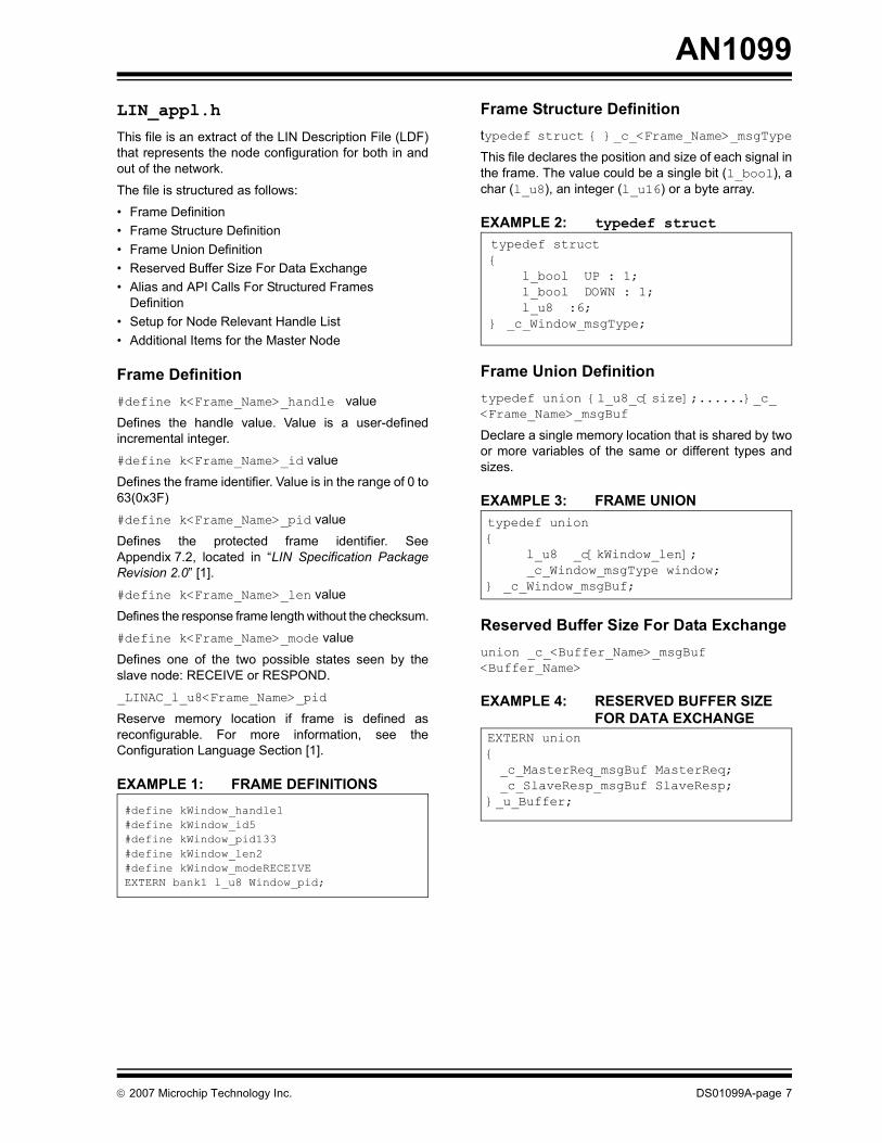
LIN_appl.hThis file is an extract of the LIN Description File (LDF)that represents the node configuration for both in andout of the network.
The file is structured as follows:
• Frame Definition• Frame Structure Definition• Frame Union Definition• Reserved Buffer Size For Data Exchange • Alias and API Calls For Structured Frames
Definition• Setup for Node Relevant Handle List• Additional Items for the Master Node
Frame Definition#define k<Frame_Name>_handle value
Defines the handle value. Value is a user-definedincremental integer.
#define k<Frame_Name>_id value
Defines the frame identifier. Value is in the range of 0 to63(0x3F)
#define k<Frame_Name>_pid value
Defines the protected frame identifier. SeeAppendix 7.2, located in “LIN Specification PackageRevision 2.0” [1].
#define k<Frame_Name>_len value
Defines the response frame length without the checksum.
#define k<Frame_Name>_mode value
Defines one of the two possible states seen by theslave node: RECEIVE or RESPOND.
_LINAC_l_u8<Frame_Name>_pid
Reserve memory location if frame is defined asreconfigurable. For more information, see theConfiguration Language Section [1].
EXAMPLE 1: FRAME DEFINITIONS
Frame Structure Definitiontypedef struct { }_c_<Frame_Name>_msgType
This file declares the position and size of each signal inthe frame. The value could be a single bit (l_bool), achar (l_u8), an integer (l_u16) or a byte array.
EXAMPLE 2: typedef struct
Frame Union Definitiontypedef union {l_u8_c[size];......}_c_<Frame_Name>_msgBuf
Declare a single memory location that is shared by twoor more variables of the same or different types andsizes.
EXAMPLE 3: FRAME UNION
Reserved Buffer Size For Data Exchange union _c_<Buffer_Name>_msgBuf<Buffer_Name>
EXAMPLE 4: RESERVED BUFFER SIZE FOR DATA EXCHANGE
#define kWindow_handle1#define kWindow_id5#define kWindow_pid133#define kWindow_len2#define kWindow_modeRECEIVEEXTERN bank1 l_u8 Window_pid;
typedef struct { l_bool UP : 1; l_bool DOWN : 1; l_u8 :6;} _c_Window_msgType;
typedef union { l_u8 _c[kWindow_len]; _c_Window_msgType window;} _c_Window_msgBuf;
EXTERN union{_c_MasterReq_msgBuf MasterReq;_c_SlaveResp_msgBuf SlaveResp;
}_u_Buffer;
© 2007 Microchip Technology Inc. DS01099A-page 7

AN1099
Alias and API Calls For Structured Frames DefinitionAlias allows the user to assign any name to a call orcommand.EXAMPLE 5: ASSIGN NAME (ALIAS)
API call assigns a command to a call that conforms tothe API format.
EXAMPLE 6: API CALL FOR API FORMAT
Setup for Node Relevant Handle ListThis array defines how a response frame shouldrespond to a specific protected identifier in a node.There are two types of structures for this array (seeExamples 7 and 8), depending on the LIN specificationrevision.
EXAMPLE 7: LIN SPECIFICATION 2.0
EXAMPLE 8: LIN SPECIFICATION 1.X
The code in the examples above are further definedbelow:
l_target_mode:The direction of data flow,RECEIVE or RESPOND.
l_target_addr:Pointer to reserved memorylocation for frame data.
l_target_len: Length of response excluding thechecksum.
l_target_MID: Message ID needed for reconfigura-tion using the AssignFrameID().If no MID available, set to 0xFFFF.
l_id_addr: Pointer to reserved memorylocation of reconfigurable frame. Ifframe is not configurable, setpointer to 0xFFFF.
The array contains at least one constant setup so iffunction l_ifc_pid_to_handle() in LINhandle.creturns with ‘0’, the driver is reconfigured to wait for thenext Sync Break.
#define UP Window.window.UP#define DOWN Window.window.DOWN#define ButtonInfo Window._c[0]
#define l_bool_rd_UP() (UP)#define l_bool_wr_UP(a) UP = a#define l_bool_rd_DOWN() (DOWN)#define l_bool_wr_DOWN(a) DOWN = a
typedef struct {
l_u8 l_target_mode;l_u8 * l_target_addr;l_u8 l_target_len;l_u16 l_target_MID;l_u8 *l_id_addr;
}l_table_s;
typedef struct {
l_u8 l_target_mode;l_u8 * l_target_addr;l_u8 l_target_len;
}l_table_s;
DS01099A-page 8 © 2007 Microchip Technology Inc.

AN1099
Master Node Setup
REFERENCES[1] “LIN Specification Package Revision 2.0”, LIN
Consortium, http://www.lin-subbus.org.
[2] “AN1009, LIN 2.0 Compliant Driver Using thePIC18XXXX Family Microcontrollers”.
[3] “AN944, Using the EUSART on the PIC16F688”.
CONFORMANCE TESTINGThis driver has passed the LIN 2.0 Conformancetesting performed by IHR.
APPENDIX: SOURCE CODEThe generic source code files and the slave exampledriver project file can be downloaded fromwww.microchip.com.
Slave example contains the following files:
- example_slave.c
- LINbasic.c
- LINhandle.c
- delay.c
- LINbasic.h
- LIN_appl.h
- delay.h
- lin_cfg.h
- controller.h
- lincom_appl.h
Note: The PIC16FXXX family device is nottypically used as the master node. Pleaserefer to Microchip application note, AN1009for the master node setup.
© 2007 Microchip Technology Inc. DS01099A-page 9

AN1099
NOTES:DS01099A-page 10 © 2007 Microchip Technology Inc.

Note the following details of the code protection feature on Microchip devices:• Microchip products meet the specification contained in their particular Microchip Data Sheet.
• Microchip believes that its family of products is one of the most secure families of its kind on the market today, when used in the intended manner and under normal conditions.
• There are dishonest and possibly illegal methods used to breach the code protection feature. All of these methods, to our knowledge, require using the Microchip products in a manner outside the operating specifications contained in Microchip’s Data Sheets. Most likely, the person doing so is engaged in theft of intellectual property.
• Microchip is willing to work with the customer who is concerned about the integrity of their code.
• Neither Microchip nor any other semiconductor manufacturer can guarantee the security of their code. Code protection does not mean that we are guaranteeing the product as “unbreakable.”
Code protection is constantly evolving. We at Microchip are committed to continuously improving the code protection features of ourproducts. Attempts to break Microchip’s code protection feature may be a violation of the Digital Millennium Copyright Act. If such actsallow unauthorized access to your software or other copyrighted work, you may have a right to sue for relief under that Act.
Information contained in this publication regarding deviceapplications and the like is provided only for your convenienceand may be superseded by updates. It is your responsibility toensure that your application meets with your specifications.MICROCHIP MAKES NO REPRESENTATIONS ORWARRANTIES OF ANY KIND WHETHER EXPRESS ORIMPLIED, WRITTEN OR ORAL, STATUTORY OROTHERWISE, RELATED TO THE INFORMATION,INCLUDING BUT NOT LIMITED TO ITS CONDITION,QUALITY, PERFORMANCE, MERCHANTABILITY ORFITNESS FOR PURPOSE. Microchip disclaims all liabilityarising from this information and its use. Use of Microchipdevices in life support and/or safety applications is entirely atthe buyer’s risk, and the buyer agrees to defend, indemnify andhold harmless Microchip from any and all damages, claims,suits, or expenses resulting from such use. No licenses areconveyed, implicitly or otherwise, under any Microchipintellectual property rights.
© 2007 Microchip Technology Inc.
Trademarks
The Microchip name and logo, the Microchip logo, Accuron, dsPIC, KEELOQ, KEELOQ logo, microID, MPLAB, PIC, PICmicro, PICSTART, PRO MATE, rfPIC and SmartShunt are registered trademarks of Microchip Technology Incorporated in the U.S.A. and other countries.
AmpLab, FilterLab, Linear Active Thermistor, Migratable Memory, MXDEV, MXLAB, SEEVAL, SmartSensor and The Embedded Control Solutions Company are registered trademarks of Microchip Technology Incorporated in the U.S.A.
Analog-for-the-Digital Age, Application Maestro, CodeGuard, dsPICDEM, dsPICDEM.net, dsPICworks, ECAN, ECONOMONITOR, FanSense, FlexROM, fuzzyLAB, In-Circuit Serial Programming, ICSP, ICEPIC, Mindi, MiWi, MPASM, MPLAB Certified logo, MPLIB, MPLINK, PICkit, PICDEM, PICDEM.net, PICLAB, PICtail, PowerCal, PowerInfo, PowerMate, PowerTool, REAL ICE, rfLAB, Select Mode, Smart Serial, SmartTel, Total Endurance, UNI/O, WiperLock and ZENA are trademarks of Microchip Technology Incorporated in the U.S.A. and other countries.
SQTP is a service mark of Microchip Technology Incorporated in the U.S.A.
All other trademarks mentioned herein are property of their respective companies.
© 2007, Microchip Technology Incorporated, Printed in the U.S.A., All Rights Reserved.
Printed on recycled paper.
DS01099A-page 11
Microchip received ISO/TS-16949:2002 certification for its worldwide headquarters, design and wafer fabrication facilities in Chandler and Tempe, Arizona; Gresham, Oregon and design centers in California and India. The Company’s quality system processes and procedures are for its PIC® MCUs and dsPIC® DSCs, KEELOQ® code hopping devices, Serial EEPROMs, microperipherals, nonvolatile memory and analog products. In addition, Microchip’s quality system for the design and manufacture of development systems is ISO 9001:2000 certified.

DS01099A-page 12 © 2006 Microchip Technology Inc.
AMERICASCorporate Office2355 West Chandler Blvd.Chandler, AZ 85224-6199Tel: 480-792-7200 Fax: 480-792-7277Technical Support: http://support.microchip.comWeb Address: www.microchip.comAtlantaDuluth, GA Tel: 678-957-9614 Fax: 678-957-1455BostonWestborough, MA Tel: 774-760-0087 Fax: 774-760-0088ChicagoItasca, IL Tel: 630-285-0071 Fax: 630-285-0075DallasAddison, TX Tel: 972-818-7423 Fax: 972-818-2924DetroitFarmington Hills, MI Tel: 248-538-2250Fax: 248-538-2260KokomoKokomo, IN Tel: 765-864-8360Fax: 765-864-8387Los AngelesMission Viejo, CA Tel: 949-462-9523 Fax: 949-462-9608Santa ClaraSanta Clara, CA Tel: 408-961-6444Fax: 408-961-6445TorontoMississauga, Ontario, CanadaTel: 905-673-0699 Fax: 905-673-6509
ASIA/PACIFICAsia Pacific OfficeSuites 3707-14, 37th FloorTower 6, The GatewayHarbour City, KowloonHong KongTel: 852-2401-1200Fax: 852-2401-3431Australia - SydneyTel: 61-2-9868-6733Fax: 61-2-9868-6755China - BeijingTel: 86-10-8528-2100 Fax: 86-10-8528-2104China - ChengduTel: 86-28-8665-5511Fax: 86-28-8665-7889China - FuzhouTel: 86-591-8750-3506 Fax: 86-591-8750-3521China - Hong Kong SARTel: 852-2401-1200 Fax: 852-2401-3431China - QingdaoTel: 86-532-8502-7355Fax: 86-532-8502-7205China - ShanghaiTel: 86-21-5407-5533 Fax: 86-21-5407-5066China - ShenyangTel: 86-24-2334-2829Fax: 86-24-2334-2393China - ShenzhenTel: 86-755-8203-2660 Fax: 86-755-8203-1760China - ShundeTel: 86-757-2839-5507 Fax: 86-757-2839-5571China - WuhanTel: 86-27-5980-5300Fax: 86-27-5980-5118China - XianTel: 86-29-8833-7250Fax: 86-29-8833-7256
ASIA/PACIFICIndia - BangaloreTel: 91-80-4182-8400 Fax: 91-80-4182-8422India - New DelhiTel: 91-11-4160-8631Fax: 91-11-4160-8632India - PuneTel: 91-20-2566-1512Fax: 91-20-2566-1513Japan - YokohamaTel: 81-45-471- 6166 Fax: 81-45-471-6122Korea - GumiTel: 82-54-473-4301Fax: 82-54-473-4302Korea - SeoulTel: 82-2-554-7200Fax: 82-2-558-5932 or 82-2-558-5934Malaysia - PenangTel: 60-4-646-8870Fax: 60-4-646-5086Philippines - ManilaTel: 63-2-634-9065Fax: 63-2-634-9069SingaporeTel: 65-6334-8870Fax: 65-6334-8850Taiwan - Hsin ChuTel: 886-3-572-9526Fax: 886-3-572-6459Taiwan - KaohsiungTel: 886-7-536-4818Fax: 886-7-536-4803Taiwan - TaipeiTel: 886-2-2500-6610 Fax: 886-2-2508-0102Thailand - BangkokTel: 66-2-694-1351Fax: 66-2-694-1350
EUROPEAustria - WelsTel: 43-7242-2244-39Fax: 43-7242-2244-393Denmark - CopenhagenTel: 45-4450-2828 Fax: 45-4485-2829France - ParisTel: 33-1-69-53-63-20 Fax: 33-1-69-30-90-79Germany - MunichTel: 49-89-627-144-0 Fax: 49-89-627-144-44Italy - Milan Tel: 39-0331-742611 Fax: 39-0331-466781Netherlands - DrunenTel: 31-416-690399 Fax: 31-416-690340Spain - MadridTel: 34-91-708-08-90Fax: 34-91-708-08-91UK - WokinghamTel: 44-118-921-5869Fax: 44-118-921-5820
WORLDWIDE SALES AND SERVICE
12/08/06


![[MS-RNDIS]: Remote Network Driver Interface Specification ... · through the RNDIS-compliant device. The protocol enables the host to provide a vendor-independent class driver for](https://img.pdfslide.us/doc/110x75/5f394d92225dcc1cb20005a2/ms-rndis-remote-network-driver-interface-specification-through-the-rndis-compliant.jpg)