Embed Size (px)
Citation preview

Standard ECMA-237June 1996
S t a n d a r d i z i n g I n f o r ma t i o n a n d C o mmu n i c a t i o n S y s t e ms
Phone: +41 22 849.60.00 - Fax: +41 22 849.60.01 - URL: h t tp : / /www.ecma.ch - In ternet : he [email protected]
Limits and Methods ofMeasurement of ImmunityCharacteristics of InformationTechnology Equipment

Standard ECMA-237June 1996
S t a n d a r d i z i n g I n f o r ma t i o n a n d C o mmu n i c a t i o n S y s t e ms
Phone: +41 22 849.60.00 - Fax: +41 22 849.60.01 - URL: h t tp : / /www.ecma.ch - In ternet : he [email protected]
IW - ECMA-237.DOC - 08.07.96 11,01
Limits and Methods ofMeasurement of ImmunityCharacteristics of InformationTechnology Equipment

Brief History
This Standard is an ECMA publication embracing the immunity requirements for information technology equipment (ITE) withregard to electromagnetic phenomena.
This ECMA Standard defines the performance criteria and the procedures for testing the immunity of ITE.
This Standard has been prepared by Technical Committee ECMA TC20, and is based upon the practical experience of ECMAmember companies and the results of their active and continuous participation in the work of Subcommittee G (interferencecharacteristics of ITE) of the International Special Committee on Radio Interference (CISPR) of the InternationalElectrotechnical Commission (IEC), as well as other international and national standardization bodies. It represents a pragmaticand widely based consensus.
This Standard references CISPR Publication 22, various IEC publications and one draft publication, as basic standards. Thesepublications form a part of this Standard.
NOTE
Where the relevant basic standard has not been issued, a draft standard may be included as an informative annex.
This ECMA Standard has been adopted by the ECMA General Assembly of June 1996.

- i -
Table of contents
Page
1 Scope 1
2 Conformance 1
3 Normative references 1
3.1 IEC publications 1
3.2 ISO publications 2
3.3 CCITT Recommendations 2
4 Definitions 2
4.1 Cable port 2
4.2 Call 2
4.3 Clear a connection 2
4.4 Continuous wave (CW) 2
4.5 Degradation 2
4.6 Enclosure port 2
4.7 Equipment under test (EUT) 2
4.8 Establish a connection 2
4.9 Information technology equipment (ITE) 2
4.10 Jitter (spatial instability) 3
4.11 Maintain a connection 3
4.12 Network terminator (NT) 3
4.13 Operating status 3
4.14 Port 3
4.15 Receive a connection 3
4.16 Telecommunication port 3
4.17 Telecommunications terminal equipment (TTE) 3
4.18 Telephony service 3
5 Acronyms, abbreviations, and notational conventions 3
6 Immunity testing requirements 4
6.1 General requirements 4
6.2 Specific requirements 4
6.2.1 Electrostatic discharge (ESD) 4
6.2.2 Continuous radio frequency disturbances 5
6.2.3 Electrical fast transients (EFT) 6
6.2.4 Surge 6
6.2.5 Power frequency magnetic fields 6
6.2.6 Voltage dips and interruptions 6
- i i -
7 Test conditions 6
7.1 General test conditions 6
7.1.1 General test configuration 6
7.1.2 General operating conditions 7
7.1.3 General environmental conditions 7
7.2 Specific test conditions 7
8 Performance criteria 8
8.1 General performance criteria 8
8.1.1 Performance criterion A 8
8.1.2 Performance criterion B 8
8.1.3 Performance criterion C 8
8.2 Specific performance criteria 8
9 Test report 9
Annex A1 - Central processing unit (CPU) 13
Annex A2 -Visual display unit (VDU) 15
Annex A3 - Input device 17
Annex A4 - Local area network (LAN) equipment 19
Annex A5 - Printer 21
Annex A6 - Copier 23
Annex A7 - Automatic teller machine (ATM) and point of sale terminal (POST) 25
Annex A8 - Facsimile 27
Annex A9 -Telecommunications terminal equipment (TTE) 29
1 ScopeThis Standard applies to information technology equipment (ITE) as defined in sub-clause 4.9.
Procedures are defined for the measurement of ITE, and limits are specified which are developed for ITE and withinthe frequency range of 0 Hz to 400 GHz. Testing is not required at frequencies and for phenomena for which no limitsare specified. Owing to testing and performance assessment considerations, some tests are specified in definedfrequency bands or at selected frequencies. Equipment which fulfills the requirements at these frequencies is deemed tofulfill the requirements in the frequency range 0 Hz to 400 GHz for electromagnetic phenomena.
The objective of this Standard is to establish uniform requirements which will provide an adequate level of intrinsicimmunity so that equipment will operate as intended in its environment, to establish methods of testing by reference toapplicable basic standards, and to standardize operating procedures, performance criteria and interpretation of testresults.
Immunity test requirements for equipment are defined in relation to continuous and transient, conducted and radiateddisturbances including electrostatic discharges.
For harsh environments, special mitigation measures may be required to ensure satisfactory operation of equipment.
Additional annexes may be added into a future edition of this Standard to meet wider needs as they arise
2 ConformanceITE is in conformance with this Standard if it satisfies all the requirements of this Standard.
3 Normative referencesThis Standard incorporates, by dated or undated reference, provisions from other publications. These references arecited at appropriate places in the text, and the publications referenced are listed hereafter. For dated references,subsequent amendments to, or revisions of, any of these publications apply to this Standard only when incorporated init by amendment or revision. For undated references, the latest edition of the publication referred to applies.
3.1 IEC publicationsCISPR 22 (1993) Limits and methods of measurement of radio interference characteristics of information
technology equipment (Amdt 1. 1995)
IEC 50(161) International electrotechnical vocabulary (IEV) - Chapter 161: Electromagneticcompatibility
IEC 318 An IEC artificial ear, of the wide band type, for the calibration of earphones used inaudiometry
IEC 651 Sound level meters
IEC 1000-4-2:1995 Electromagnetic compatibility (EMC), Part 2: Testing and measurement techniques,Section 2: Electrostatic discharge immunity test - Basic EMC Publication
IEC 1000-4-3:1995 Electromagnetic compatibility (EMC), Part 3: Testing and measurement techniques,Section 3: Radiated radio-frequency electromagnetic field immunity test (revision ofIEC 801-3)
IEC 1000-4-4:1995 Electromagnetic compatibility (EMC), Part 4: Testing and measurement techniques,Section 4: Electrical fast transient / burst immunity test - Basic EMC Publication
IEC 1000-4-5:1995 Electromagnetic compatibility (EMC), Part 5: Testing and measurement techniques,Section 5: Surge immunity test
IEC 1000-4-6: Draft Electromagnetic Compatibility (EMC), Part 6: Testing and measurement techniques,Section 6: Immunity to conducted disturbances induced by radio frequency fields
IEC 1000-4-8:1993 Electromagnetic compatibility (EMC), Part 8: Testing and measurement techniques,Section 8: Power frequency magnetic field immunity test - Basic EMC Publication
- 2 -
IEC 1000-4-11:1994 Electromagnetic compatibility (EMC), Part 11: Testing and measurement techniques,Section 11: Voltage dips, short interruptions and voltage variations immunity testsBasic EMC publication
3.2 ISO publicationsISO 9241-3:1992 Ergonomic requirements for office work with visual display terminals (VDTs), Part 3:
Visual display requirements
3.3 CCITT RecommendationsRec. I.241.1 Teleservices supported by an ISDN - Telephony (1988)
Rec. I.411 ISDN user network interfaces - Reference configuration (1993)
4 DefinitionsFor the purpose of this Standard, the definitions contained in CCITT Rec. I.411 and IEC 50(161) shall apply. Inaddition the following specific definitions apply:
4.1 Cable portA point at which a conductor or a cable is connected to the equipment. Examples are signal, control and powerports.
4.2 CallThe process exercised in the network and the TTE to allow interchange of information (speech, video or data) withanother TTE through the network. See NOTE 1.
NOTE 1
The call shall be operated in the way specified by the manufacturer. For circuit-switched services, the exchange ofdata shall be considered to be possible when a 64 kbit/s channel is available for both parties. For packet services,the exchange of information shall be considered to be possible when a virtual path is established to the called TTE.
4.3 Clear a connectionThe operating procedure for a user or an automatic process in conjunction with the network (either at the initiativeof the local party or the distant party) to stop the capability of exchanging information by orderly returning to a statewhere the establishment of a new call is possible. See NOTE 1.
4.4 Continuous wave (CW)Electromagnetic waves, the successive oscillations of which are sinusoidal and identical under steady-stateconditions, which can be interrupted or modulated to convey information.
4.5 DegradationThe unwanted change in operational performance of an EUT due to electromagnetic disturbances. This does notnecessarily mean malfunction or catastrophic failure.
4.6 Enclosure portThe physical boundary of the equipment through which electromagnetic fields may radiate or impinge. For plug-inunits the physical boundary will be defined by the host equipment.
4.7 Equipment under test (EUT)A representative ITE or functionally interactive group of ITE (i.e. system) which includes one or more host unit(s)and is used for evaluation purposes.
4.8 Establish a connectionThe operating procedure for a user or an automatic process in conjunction with the network to reach the capabilityto exchange information with another TTE. See NOTE 1.
4.9 Information technology equipment (ITE)The definition of ITE is as described in CISPR Publication 22 (1993).
- 3 -
4.10 Jitter (spatial instability)Peak-to-peak variation in the geometric location of picture elements on the viewing surface of a VDU.
4.11 Maintain a connectionHaving the capability of exchanging information without having to clear and reestablish a call. See NOTE 1.
4.12 Network terminator (NT)Ancillary equipment representing the termination of the telecommunication network.
4.13 Operating statusMode of operation and condition of any indicators (software or hardware), stored functions and data.
4.14 PortParticular interface of the specified equipment with the external electromagnetic environment (see figure 1).
DC power port Equipment under test Signal port
AC power port (EUT) Telecommunications port
Figure 1 - Types of port
4.15 Receive a connectionThe operating procedure for a user or an automatic process initiated by and in conjunction with the network to reachthe capability to exchange information with another TTE. See NOTE 1.
4.16 Telecommunication portPort which is intended to be connected to public telephone network.
4.17 Telecommunications terminal equipment (TTE)Equipment intended to be connected to a public or private telecommunications network; i.e.
a) to be connected directly to the termination of a telecommunications network, or
b) to interwork with a telecommunications network being connected directly or indirectly to the termination of atelecommunications network in order to send, process or receive information.
4.18 Telephony serviceTelephony service provides users with the ability for real-time two-way speech conversation via the network (seeCCITT Rec. I.241.1).
5 Acronyms, abbreviations, and notational conventionsCISPR International Special Committee on Radio Interference
CPU Central processing unit
CRT Cathode ray tube
CW Continuous wave
EFT Electrical fast transients
EMC Electromagnetic compatibility
ESD Electrostatic discharge
EUT Equipment under test

- 4 -
IEC International Electrotechnical Commission
IEV International electrotechnical vocabulary
I/O Input/output
ISO International Organization for Standardization
ITE Information technology equipment
ITU International Telecommunication Union
ITU-T International Telecommunication Union - Telecommunications (Standardization)
NT Network terminator
RAM Random access memory
RF Radio frequency
TTE Telecommunications terminal equipment
VDT Video display terminal
VDU Video display unit
6 Immunity testing requirements6.1 General requirements
The immunity test requirements for equipment within the scope of this Standard are given on a port-by-port basis intable 1. The test parameters for the various tests are given in table 2. Tests shall only be performed where therelevant ports exist.
It may be determined from consideration of the electrical characteristics and usage of a particular EUT that some ofthe tests are inappropriate and therefore unnecessary. In such a case, both the decision and the justification not toapply any particular test to any particular port shall be recorded in the test report.
The description of the test, the test generator, the test methods and the test set-up are given in IEC basic standardswhich are referenced in table 2. The contents of these IEC basic standards are not duplicated in this Standard.However, modifications or additional information needed for the practical application of the tests are given in 6.2below.
Tests shall be conducted in a well-defined and reproducible manner.
The tests shall be performed as single tests in sequence. The sequence of testing is optional.
6.2 Specific requirements6.2.1 Electrostatic discharge (ESD)
The electrostatic discharges shall be applied only to those points and surfaces of the EUT which the user is likelyto touch during normal operations, including user access, as specified in the user manual. Discharges to openconnectors are excluded from ESD testing.
The discharges shall be applied in two ways:
a) Contact discharge to conductive surfaces and to coupling planes:
The EUT shall be subjected to at least 200 discharges, 100 each at negative and positive polarity, at aminimum of four test points, with a minimum of 50 discharges to each point. One of the test points shall bethe centre of the front edge of the horizontal coupling plane which shall be subjected to 50 discharges. Theremaining three test points shall each receive at least 50 direct contact discharges. If no direct contact testpoints are available, then at least 200 indirect discharges shall be applied in the most sensitive polarity. Forfinal tests, the maximum repetition rate shall be 1 discharge per second.
b) Air discharge at slots and aperatures, and insulating surfaces:
On those parts of the EUT where it is not possible to perform contact discharge testing, the product shall beinvestigated to identify user accessible points where breakdown may occur; examples are openings at edges of
- 5 -
keys or in the covers of keyboards and telephone handsets. Such points are tested using the air dischargemethod (see also IEC 1000-4-2, sub-clause 8.3.1 regarding painted surfaces). This investigation should berestricted to those areas normally handled by the user. A minimum of ten single air discharges shall be appliedto the selected test point for each such area.
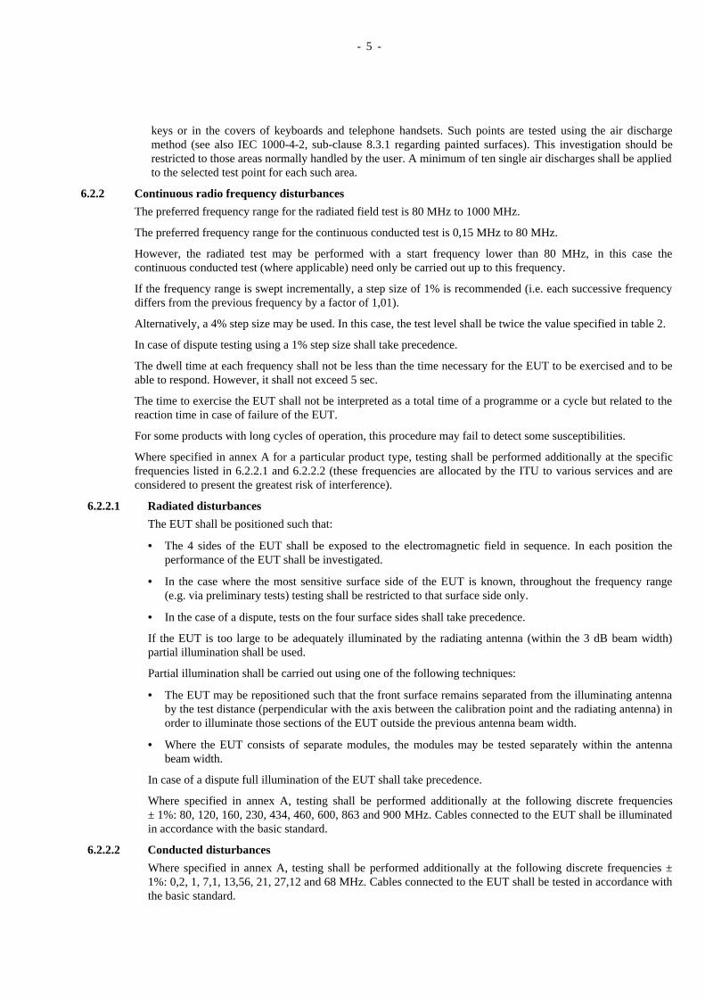
6.2.2 Continuous radio frequency disturbances
The preferred frequency range for the radiated field test is 80 MHz to 1000 MHz.
The preferred frequency range for the continuous conducted test is 0,15 MHz to 80 MHz.
However, the radiated test may be performed with a start frequency lower than 80 MHz, in this case thecontinuous conducted test (where applicable) need only be carried out up to this frequency.
If the frequency range is swept incrementally, a step size of 1% is recommended (i.e. each successive frequencydiffers from the previous frequency by a factor of 1,01).
Alternatively, a 4% step size may be used. In this case, the test level shall be twice the value specified in table 2.
In case of dispute testing using a 1% step size shall take precedence.
The dwell time at each frequency shall not be less than the time necessary for the EUT to be exercised and to beable to respond. However, it shall not exceed 5 sec.
The time to exercise the EUT shall not be interpreted as a total time of a programme or a cycle but related to thereaction time in case of failure of the EUT.
For some products with long cycles of operation, this procedure may fail to detect some susceptibilities.
Where specified in annex A for a particular product type, testing shall be performed additionally at the specificfrequencies listed in 6.2.2.1 and 6.2.2.2 (these frequencies are allocated by the ITU to various services and areconsidered to present the greatest risk of interference).
6.2.2.1 Radiated disturbances
The EUT shall be positioned such that:
• The 4 sides of the EUT shall be exposed to the electromagnetic field in sequence. In each position theperformance of the EUT shall be investigated.
• In the case where the most sensitive surface side of the EUT is known, throughout the frequency range(e.g. via preliminary tests) testing shall be restricted to that surface side only.
• In the case of a dispute, tests on the four surface sides shall take precedence.
If the EUT is too large to be adequately illuminated by the radiating antenna (within the 3 dB beam width)partial illumination shall be used.
Partial illumination shall be carried out using one of the following techniques:
• The EUT may be repositioned such that the front surface remains separated from the illuminating antennaby the test distance (perpendicular with the axis between the calibration point and the radiating antenna) inorder to illuminate those sections of the EUT outside the previous antenna beam width.
• Where the EUT consists of separate modules, the modules may be tested separately within the antennabeam width.
In case of a dispute full illumination of the EUT shall take precedence.
Where specified in annex A, testing shall be performed additionally at the following discrete frequencies± 1%: 80, 120, 160, 230, 434, 460, 600, 863 and 900 MHz. Cables connected to the EUT shall be illuminatedin accordance with the basic standard.
6.2.2.2 Conducted disturbances
Where specified in annex A, testing shall be performed additionally at the following discrete frequencies ±1%: 0,2, 1, 7,1, 13,56, 21, 27,12 and 68 MHz. Cables connected to the EUT shall be tested in accordance withthe basic standard.

- 6 -
6.2.3 Electrical fast transients (EFT)
The test equipment and method are given in clauses 6 and 7 of IEC 1000-4-4. However, sub-clause 7.3 (Test set-up for post installation tests) is not applicable for ITE.
The test procedure is given in sub-clauses 8.1, 8.1.1, 8.1.2 and 8.2 of IEC 1000-4-4 together with the followingchanges/clarifications:
• Where there is more than one identical port, only one of each port shall be tested.
• Multi-conductor cables, such as 50 pair telecommunication cables, are tested as a single cable. Cables shallnot be split or divided into groups of conductors for this test.
• Interface ports which are not intended by the manufacturer to have data cables shorter than 3 m connected tothem shall not be tested.
6.2.4 Surge
6.2.4.1 AC and DC input power ports
A 10 ohm resistor shall be used in series with the generator to give a source impedance of 12 ohms.
For DC input ports, the surges shall be applied between line and ground.
6.2.4.2 Signal and telecommunication ports
A 40 ohm resistor shall be used in series with the generator, to give a source impedance of 42 ohms.
The surges shall be applied between all lines and ground simultaneously.
6.2.5 Power frequency magnetic fields
• The EUT shall be arranged and connected to satisfy its functional requirements; and shall be placed at thecentre of the coil system (immersion method of IEC 1000-4-8). The direction of the magnetic field shall bevertical. If the construction of the VDU is such that a different jitter magnitude may be expected from a fieldof a different orientation then the EUT shall also be tested in an horizontal field.
• The cables supplied by the equipment manufacturer shall be used, or in their absence suitable alternativecables shall be used, of the type proper for the signals involved.
The EUT shall be immersed in a sinusoidal magnetic field whose frequency is equivalent to the electricity supplyfrequency in the intended environment.
If a magnetic field of 0,4 A/m is applied, as specified in table 2, the jitter shall be measured using a measuringmicroscope as specified in 6.6.14 of ISO 9241-3.
Alternatively, a magnetic field of 20 A/m may be applied, and a transparent graduated mask may be used toassess the jitter. In this case, there is a corresponding increase in the allowed jitter. See A2.2 in annex A2.
6.2.6 Voltage dips and interruptions
Voltage dips and interruptions as specified in table 2 shall be applied, with the change occurring at the zero-degree phase of the voltage waveform.
7 Test conditions7.1 General test conditions
7.1.1 General test configuration
The EUT shall be configured, installed, arranged and operated in a manner consistent with typical applications.
An EUT which may be populated with multiple modules (e.g. plug-in cards, disk drives, etc.) shall be tested witha mix and number representative of a typical installation.
If the EUT may be part of a system, or may be connected to auxiliary equipment, then the EUT shall be tested ina minimum representative configuration, whose mix and number of units is representative of a typicalinstallation.
- 7 -
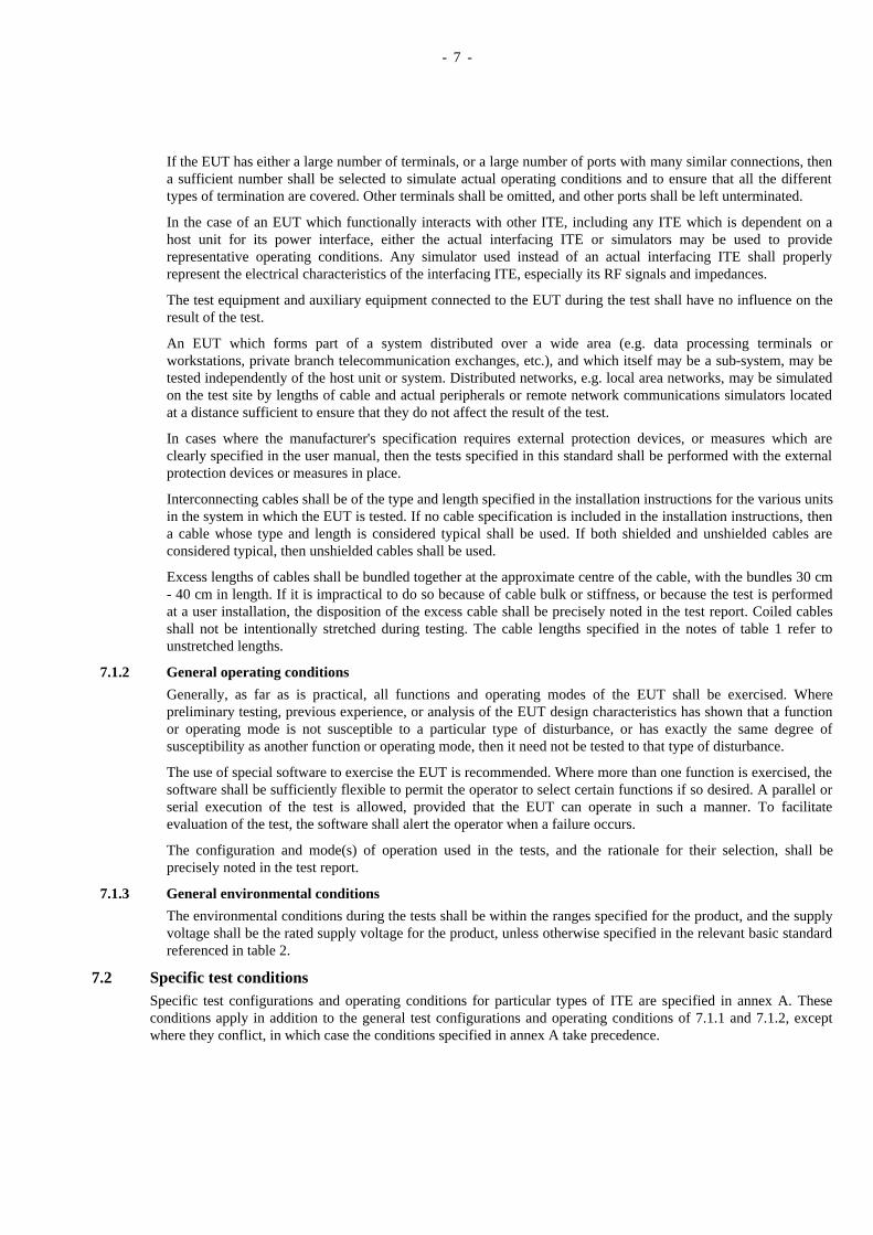
If the EUT has either a large number of terminals, or a large number of ports with many similar connections, thena sufficient number shall be selected to simulate actual operating conditions and to ensure that all the differenttypes of termination are covered. Other terminals shall be omitted, and other ports shall be left unterminated.
In the case of an EUT which functionally interacts with other ITE, including any ITE which is dependent on ahost unit for its power interface, either the actual interfacing ITE or simulators may be used to providerepresentative operating conditions. Any simulator used instead of an actual interfacing ITE shall properlyrepresent the electrical characteristics of the interfacing ITE, especially its RF signals and impedances.
The test equipment and auxiliary equipment connected to the EUT during the test shall have no influence on theresult of the test.
An EUT which forms part of a system distributed over a wide area (e.g. data processing terminals orworkstations, private branch telecommunication exchanges, etc.), and which itself may be a sub-system, may betested independently of the host unit or system. Distributed networks, e.g. local area networks, may be simulatedon the test site by lengths of cable and actual peripherals or remote network communications simulators locatedat a distance sufficient to ensure that they do not affect the result of the test.
In cases where the manufacturer's specification requires external protection devices, or measures which areclearly specified in the user manual, then the tests specified in this standard shall be performed with the externalprotection devices or measures in place.
Interconnecting cables shall be of the type and length specified in the installation instructions for the various unitsin the system in which the EUT is tested. If no cable specification is included in the installation instructions, thena cable whose type and length is considered typical shall be used. If both shielded and unshielded cables areconsidered typical, then unshielded cables shall be used.
Excess lengths of cables shall be bundled together at the approximate centre of the cable, with the bundles 30 cm- 40 cm in length. If it is impractical to do so because of cable bulk or stiffness, or because the test is performedat a user installation, the disposition of the excess cable shall be precisely noted in the test report. Coiled cablesshall not be intentionally stretched during testing. The cable lengths specified in the notes of table 1 refer tounstretched lengths.
7.1.2 General operating conditions
Generally, as far as is practical, all functions and operating modes of the EUT shall be exercised. Wherepreliminary testing, previous experience, or analysis of the EUT design characteristics has shown that a functionor operating mode is not susceptible to a particular type of disturbance, or has exactly the same degree ofsusceptibility as another function or operating mode, then it need not be tested to that type of disturbance.
The use of special software to exercise the EUT is recommended. Where more than one function is exercised, thesoftware shall be sufficiently flexible to permit the operator to select certain functions if so desired. A parallel orserial execution of the test is allowed, provided that the EUT can operate in such a manner. To facilitateevaluation of the test, the software shall alert the operator when a failure occurs.
The configuration and mode(s) of operation used in the tests, and the rationale for their selection, shall beprecisely noted in the test report.
7.1.3 General environmental conditions
The environmental conditions during the tests shall be within the ranges specified for the product, and the supplyvoltage shall be the rated supply voltage for the product, unless otherwise specified in the relevant basic standardreferenced in table 2.
7.2 Specific test conditionsSpecific test configurations and operating conditions for particular types of ITE are specified in annex A. Theseconditions apply in addition to the general test configurations and operating conditions of 7.1.1 and 7.1.2, exceptwhere they conflict, in which case the conditions specified in annex A take precedence.
- 8 -
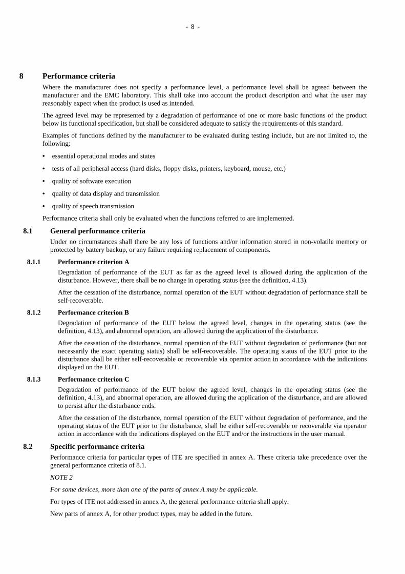
8 Performance criteriaWhere the manufacturer does not specify a performance level, a performance level shall be agreed between themanufacturer and the EMC laboratory. This shall take into account the product description and what the user mayreasonably expect when the product is used as intended.
The agreed level may be represented by a degradation of performance of one or more basic functions of the productbelow its functional specification, but shall be considered adequate to satisfy the requirements of this standard.
Examples of functions defined by the manufacturer to be evaluated during testing include, but are not limited to, thefollowing:
• essential operational modes and states
• tests of all peripheral access (hard disks, floppy disks, printers, keyboard, mouse, etc.)
• quality of software execution
• quality of data display and transmission
• quality of speech transmission
Performance criteria shall only be evaluated when the functions referred to are implemented.
8.1 General performance criteriaUnder no circumstances shall there be any loss of functions and/or information stored in non-volatile memory orprotected by battery backup, or any failure requiring replacement of components.
8.1.1 Performance criterion A
Degradation of performance of the EUT as far as the agreed level is allowed during the application of thedisturbance. However, there shall be no change in operating status (see the definition, 4.13).
After the cessation of the disturbance, normal operation of the EUT without degradation of performance shall beself-recoverable.
8.1.2 Performance criterion B
Degradation of performance of the EUT below the agreed level, changes in the operating status (see thedefinition, 4.13), and abnormal operation, are allowed during the application of the disturbance.
After the cessation of the disturbance, normal operation of the EUT without degradation of performance (but notnecessarily the exact operating status) shall be self-recoverable. The operating status of the EUT prior to thedisturbance shall be either self-recoverable or recoverable via operator action in accordance with the indicationsdisplayed on the EUT.
8.1.3 Performance criterion C
Degradation of performance of the EUT below the agreed level, changes in the operating status (see thedefinition, 4.13), and abnormal operation, are allowed during the application of the disturbance, and are allowedto persist after the disturbance ends.
After the cessation of the disturbance, normal operation of the EUT without degradation of performance, and theoperating status of the EUT prior to the disturbance, shall be either self-recoverable or recoverable via operatoraction in accordance with the indications displayed on the EUT and/or the instructions in the user manual.
8.2 Specific performance criteriaPerformance criteria for particular types of ITE are specified in annex A. These criteria take precedence over thegeneral performance criteria of 8.1.
NOTE 2
For some devices, more than one of the parts of annex A may be applicable.
For types of ITE not addressed in annex A, the general performance criteria shall apply.
New parts of annex A, for other product types, may be added in the future.
- 9 -
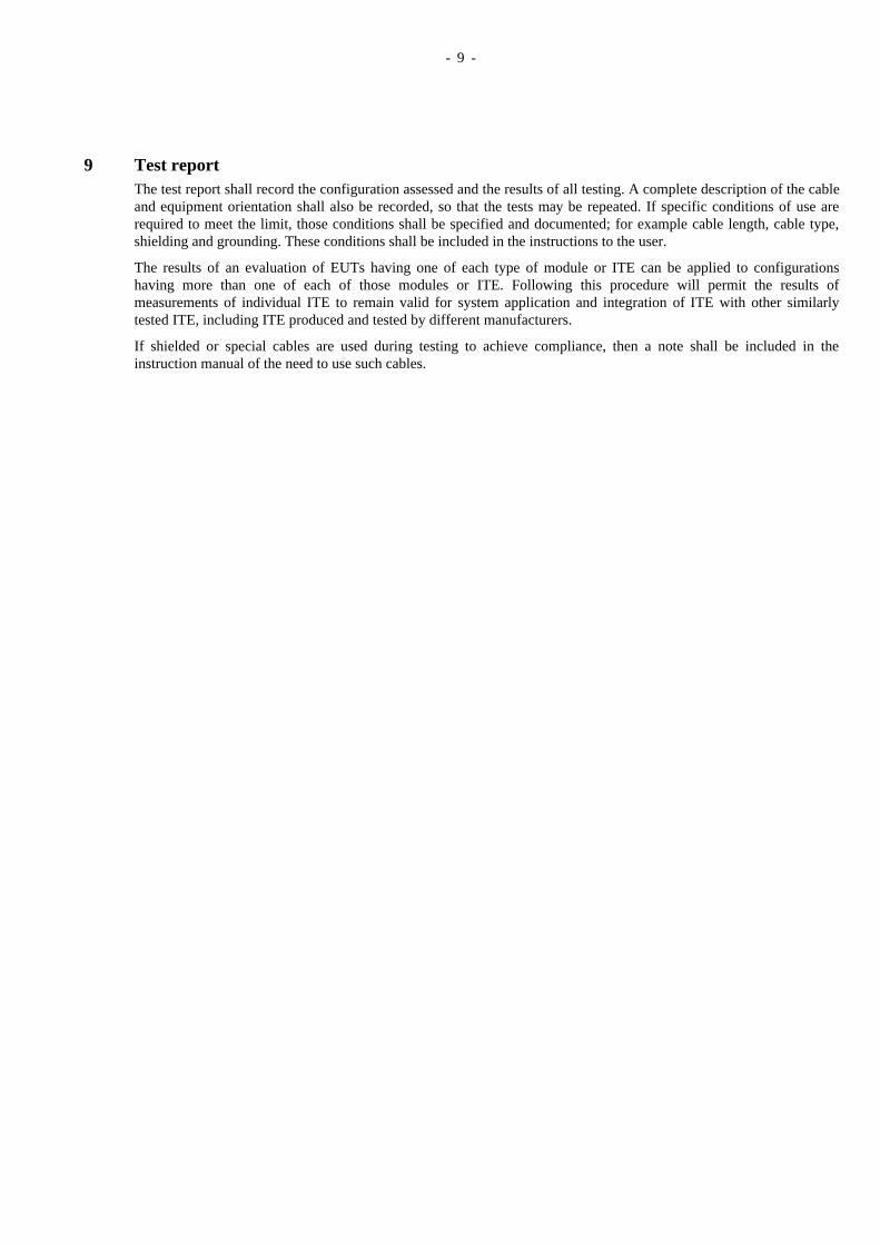
9 Test reportThe test report shall record the configuration assessed and the results of all testing. A complete description of the cableand equipment orientation shall also be recorded, so that the tests may be repeated. If specific conditions of use arerequired to meet the limit, those conditions shall be specified and documented; for example cable length, cable type,shielding and grounding. These conditions shall be included in the instructions to the user.
The results of an evaluation of EUTs having one of each type of module or ITE can be applied to configurationshaving more than one of each of those modules or ITE. Following this procedure will permit the results ofmeasurements of individual ITE to remain valid for system application and integration of ITE with other similarlytested ITE, including ITE produced and tested by different manufacturers.
If shielded or special cables are used during testing to achieve compliance, then a note shall be included in theinstruction manual of the need to use such cables.
- 10 -
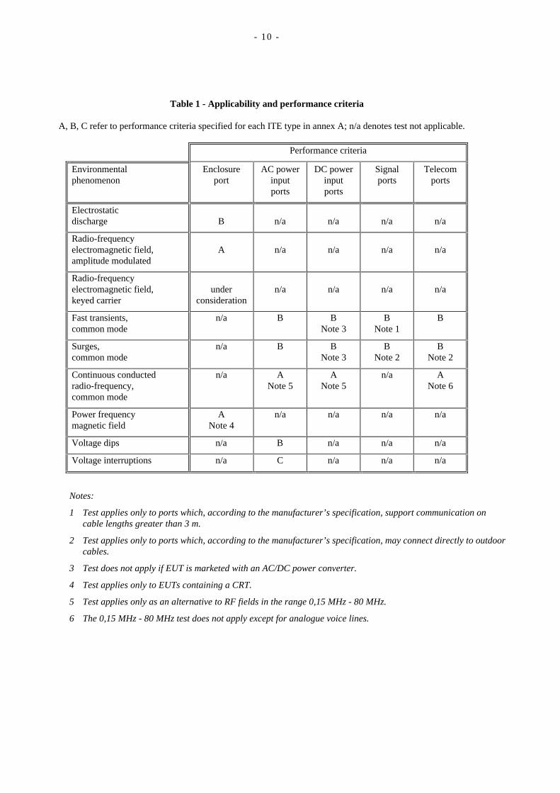
Table 1 - Applicability and performance criteria
A, B, C refer to performance criteria specified for each ITE type in annex A; n/a denotes test not applicable.
Performance criteria
Environmentalphenomenon
Enclosureport
AC powerinputports
DC powerinputports
Signalports
Telecomports
Electrostaticdischarge B n/a n/a n/a n/a
Radio-frequencyelectromagnetic field,amplitude modulated
A n/a n/a n/a n/a
Radio-frequencyelectromagnetic field,keyed carrier
underconsideration
n/a n/a n/a n/a
Fast transients,common mode
n/a B BNote 3
BNote 1
B
Surges,common mode
n/a B BNote 3
BNote 2
BNote 2
Continuous conductedradio-frequency,common mode
n/a ANote 5
ANote 5
n/a ANote 6
Power frequencymagnetic field
ANote 4
n/a n/a n/a n/a
Voltage dips n/a B n/a n/a n/a
Voltage interruptions n/a C n/a n/a n/a
Notes:
1 Test applies only to ports which, according to the manufacturer’s specification, support communication oncable lengths greater than 3 m.
2 Test applies only to ports which, according to the manufacturer’s specification, may connect directly to outdoorcables.
3 Test does not apply if EUT is marketed with an AC/DC power converter.
4 Test applies only to EUTs containing a CRT.
5 Test applies only as an alternative to RF fields in the range 0,15 MHz - 80 MHz.
6 The 0,15 MHz - 80 MHz test does not apply except for analogue voice lines.
- 11 -
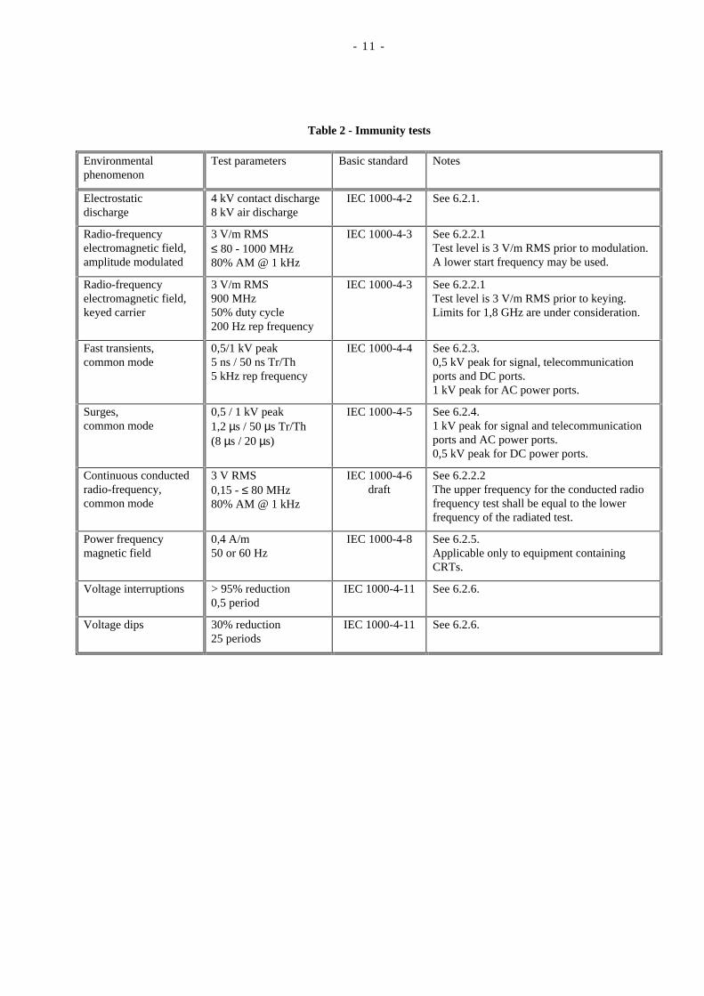
Table 2 - Immunity tests
Environmentalphenomenon
Test parameters Basic standard Notes
Electrostaticdischarge
4 kV contact discharge8 kV air discharge
IEC 1000-4-2 See 6.2.1.
Radio-frequencyelectromagnetic field,amplitude modulated
3 V/m RMS≤ 80 - 1000 MHz80% AM @ 1 kHz
IEC 1000-4-3 See 6.2.2.1Test level is 3 V/m RMS prior to modulation.A lower start frequency may be used.
Radio-frequencyelectromagnetic field,keyed carrier
3 V/m RMS900 MHz50% duty cycle200 Hz rep frequency
IEC 1000-4-3 See 6.2.2.1Test level is 3 V/m RMS prior to keying.Limits for 1,8 GHz are under consideration.
Fast transients,common mode
0,5/1 kV peak5 ns / 50 ns Tr/Th5 kHz rep frequency
IEC 1000-4-4 See 6.2.3.0,5 kV peak for signal, telecommunicationports and DC ports.1 kV peak for AC power ports.
Surges,common mode
0,5 / 1 kV peak1,2 µs / 50 µs Tr/Th(8 µs / 20 µs)
IEC 1000-4-5 See 6.2.4.1 kV peak for signal and telecommunicationports and AC power ports.0,5 kV peak for DC power ports.
Continuous conductedradio-frequency,common mode
3 V RMS0,15 - ≤ 80 MHz80% AM @ 1 kHz
IEC 1000-4-6draft
See 6.2.2.2The upper frequency for the conducted radiofrequency test shall be equal to the lowerfrequency of the radiated test.
Power frequencymagnetic field
0,4 A/m50 or 60 Hz
IEC 1000-4-8 See 6.2.5.Applicable only to equipment containingCRTs.
Voltage interruptions > 95% reduction0,5 period
IEC 1000-4-11 See 6.2.6.
Voltage dips 30% reduction25 periods
IEC 1000-4-11 See 6.2.6.

- 12 -
- 13 -
Annex A1
(normative)
Central processing unit (CPU)
A1.1 Specific test conditionsThere are no specific test conditions for CPUs. The general test conditions of clause 7.1 apply.
A1.2 Specific performance criteriaUnder no circumstances shall there be any loss of functions and/or information stored in non-volatile memory orprotected by battery backup, or any failure requiring replacement of components.
Performance criterion A
Degradation of performance of the EUT as far as the agreed level (see clause 8) is allowed during the application ofthe disturbance. However, there shall be no:
• loss or corruption of data during input/output operations
• reduction of system performance below 80% of that specified by the manufacturer
• memory errors
– loss or corruption of permanently-stored data, including data stored on permanent storage media, e.g. harddrive, optical or floppy disk
– loss or corruption of data in open or scratch file
– loss or corruption of data stored in RAM
– repeated self-recoverable errors during read/write sequences, beyond a figure specified by the manufacturer
• lack of or incorrect response to input device, e.g. keyboard, mouse, etc.
• resetting or shutting down of the system
• dropping of the network connection
• change of system state
• change of I/O state
After the cessation of the disturbance, normal operation of the EUT without degradation of performance shall be self-recoverable.
Performance criterion B
Degradation of performance of the EUT below the agreed level (see clause 8), and the effects listed under performancecriterion A, are allowed during the application of the disturbance.
After the cessation of the disturbance, normal operation of the EUT without degradation of performance (but notnecessarily the exact operating status, see the definition, 4.13) shall be self-recoverable. The operating status of theEUT prior to the disturbance shall be either self-recoverable or recoverable via operator action in accordance with theindications displayed on the EUT.

- 14 -
Performance criterion C
Degradation of performance of the EUT below the agreed level (see clause 8), and the effects listed under performancecriterion A, are allowed during the application of the disturbance, and are allowed to persist after the disturbance ends.
After the cessation of the disturbance, normal operation of the EUT without degradation of performance, and theoperating status (see the definition, 4.13) of the EUT prior to the disturbance, shall be either self-recoverable orrecoverable via operator action in accordance with the indications displayed on the EUT and/or the instructions in theuser manual.
- 15 -
Annex A2
(normative)
Visual display unit (VDU)
A2.1 Specific test conditionsThe EUT shall be connected to a central processing unit or system unit, unless it is an integral part of such a unit. Thecentral processing unit shall run an exerciser program capable of writing text and/or graphics (as applicable) to theEUT. In particular, the following shall be displayed:
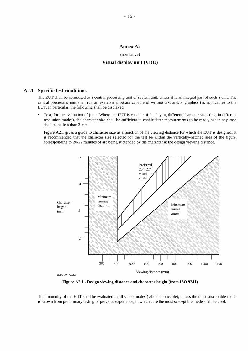
• Text, for the evaluation of jitter. Where the EUT is capable of displaying different character sizes (e.g. in differentresolution modes), the character size shall be sufficient to enable jitter measurements to be made, but in any caseshall be no less than 3 mm.
Figure A2.1 gives a guide to character size as a function of the viewing distance for which the EUT is designed. Itis recommended that the character size selected for the test be within the vertically-hatched area of the figure,corresponding to 20-22 minutes of arc being subtended by the character at the design viewing distance.
ECMA-94-0022A
300 400 500 600 700 800 900 1000 1100
2
3
4
5
Characterheight(mm)
Preferred20° - 22°visualangle
Viewing distance (mm)
Minimumvisualangle
Minimumviewingdistance
Figure A2.1 - Design viewing distance and character height (from ISO 9241)
The immunity of the EUT shall be evaluated in all video modes (where applicable), unless the most susceptible modeis known from preliminary testing or previous experience, in which case the most susceptible mode shall be used.
- 16 -
A2.2 Specific performance criteriaUnder no circumstances shall there be any loss of functions and/or information stored in non-volatile memory orprotected by battery backup, or any failure requiring replacement of components.
Performance criterion A
Degradation of performance of the EUT as far as the agreed level (see clause 8) is allowed during the application ofthe disturbance. However, there shall be no:
• loss or corruption of data during input/output operations
• loss of picture
• loss of horizontal or vertical sync
• loss of character legibility caused by missing or extra pixels
• jitter exceeding the value:
character size in mm 0,33 mm+
33,3
NOTE
If the option to perform the power frequency magnetic field immunity test with a field strength of 20 A/m is used,then the maximum allowed jitter is 50 times the value obtained from the above formula.
• unwanted change in display mode
After the cessation of the disturbance, normal operation of the EUT without degradation of performance shall be self-recoverable.
Performance criterion B
Degradation of performance of the EUT below the agreed level (see clause 8), and the effects listed under performancecriterion A, are allowed during the application of the disturbance.
After the cessation of the disturbance, normal operation of the EUT without degradation of performance (but notnecessarily the exact operating status, see the definition, 4.13) shall be self-recoverable. The operating status of theEUT prior to the disturbance shall be either self-recoverable or recoverable via operator action in accordance with theindications displayed on the EUT.
Performance criterion C
Degradation of performance of the EUT below the agreed level (see clause 8), and the effects listed under performancecriterion A, are allowed during the application of the disturbance, and are allowed to persist after the disturbance ends.
After the cessation of the disturbance, normal operation of the EUT without degradation of performance, and theoperating status (see the definition, 4.13) of the EUT prior to the disturbance, shall be either self-recoverable orrecoverable via operator action in accordance with the indications displayed on the EUT and/or the instructions in theuser manual.
- 17 -
Annex A3
(normative)
Input device
Input devices include keyboards, mice, magnetic stripe readers, character readers, image scanners, input pens andmiscellaneous sensors.
A3.1 Specific test conditionsThe EUT shall be connected to a central processing unit or system unit, unless it is an integral part of such a unit.
When the EUT is a manual input device, such as a keyboard, a VDU shall be connected to the central processing unitso that the input data can be viewed. Where possible and practicable, the EUT shall be set up to generate a continuousinput for the duration of the test. Otherwise, the test system shall be set up in input stand-by condition.
When the EUT is a mass data input device, such as a character reader or scanner, the central processing unit shall run aprogram which compares the input data with previously-stored data. Input / compare cycles shall be repeated underprogram control for the duration of the test.
A3.2 Specific performance criteriaUnder no circumstances shall there be any loss of functions and/or information stored in non-volatile memory orprotected by battery backup, or any failure requiring replacement of components.
Performance criterion A
Degradation of performance of the EUT as far as the agreed level (see clause 8) is allowed during the application ofthe disturbance. However, there shall be no:
• loss or corruption of data during input/output operations
• failure of the EUT to produce an output
• false outputs from the EUT to the system (e.g. incorrect or extra characters or cursor movements, corruption ofscanner image data)
• failure of the EUT to respond to inputs from the system
• false EUT response to inputs from the system (e.g. unwanted change of keyboard mode)
After the cessation of the disturbance, normal operation of the EUT without degradation of performance shall be self-recoverable.
Performance criterion B
Degradation of performance of the EUT below the agreed level (see clause 8), and the effects listed under performancecriterion A, are allowed during the application of the disturbance.
After the cessation of the disturbance, normal operation of the EUT without degradation of performance (but notnecessarily the exact operating status, see the definition, 4.13) shall be self-recoverable. The operating status of theEUT prior to the disturbance shall be either self-recoverable or recoverable via operator action in accordance with theindications displayed on the EUT.
Any input errors shall be capable of correction by repeating the input operation.
- 18 -
Performance criterion C
Degradation of performance of the EUT below the agreed level (see clause 8), and the effects listed under performancecriterion A, are allowed during the application of the disturbance, and are allowed to persist after the disturbance ends.
After the cessation of the disturbance, normal operation of the EUT without degradation of performance, and theoperating status (see the definition, 4.13) of the EUT prior to the disturbance, shall be either self-recoverable orrecoverable via operator action in accordance with the indications displayed on the EUT and/or the instructions in theuser manual.
Any input errors shall be capable of correction by repeating the input operation.
- 19 -
Annex A4
(normative)
Local area network (LAN) equipment
A4.1 Specific test conditionsA minimum test configuration consists of two pieces of terminal equipment interconnected with manufacturer specifiedphysical cable. Associated equipment necessary for the function of the LAN shall be included in the test configuration.
Unused ports shall be treated according the manufacturer’s instructions.
The system shall be capable of delivering and receiving data at the nominal specified transmission rate.
The cable shall have a minimum length of 10 m. For the radiated immunity test, 1,5 m of cable shall be positionedhorizontally at 0,8 m height and be exposed to the field, the rest can be bundled. The disposition of the excess cableshall be precisely noted in the test report.
The LAN equipment shall execute a programme which exercises the LAN functionalities.
A4.2 Specific performance criteriaUnder no circumstances shall there be any loss of functions and/or information stored in non-volatile memory orprotected by battery backup, or any failure requiring replacement of components.
Performance criterion A
Degradation of performance of the EUT as far as the agreed level (see clause 8) is allowed during the application ofthe disturbance. However, there shall be no:
• protocol failure (e.g. corruption of header data)
• loss of link
• error rate exceeding a figure specified by the manufacturer
• request for retry exceeding a figure specified by the manufacturer
• data transmission rate below a figure specified by the manufacturer
After the cessation of the disturbance, normal operation of the EUT without degradation of performance shall be self-recoverable.
Performance criterion B
Degradation of performance of the EUT below the agreed level (see clause 8), and the effects listed under performancecriterion A, are allowed during the application of the disturbance, except that there shall be no:
• protocol failure
• loss of link
After the cessation of the disturbance, normal operation of the EUT without degradation of performance (but notnecessarily the exact operating status, see the definition, 4.13) shall be self-recoverable. The operating status of theEUT prior to the disturbance shall be either self-recoverable or recoverable via operator action in accordance with theindications displayed on the EUT.
- 20 -
Performance criterion C
Degradation of performance of the EUT below the agreed level (see clause 8), and the effects listed under performancecriterion A, are allowed during the application of the disturbance, and are allowed to persist after the disturbance ends.
After the cessation of the disturbance, normal operation of the EUT without degradation of performance, and theoperating status (see the definition, 4.13) of the EUT prior to the disturbance, shall be either self-recoverable orrecoverable via operator action in accordance with the indications displayed on the EUT and/or the instructions in theuser manual.
- 21 -
Annex A5
(normative)
Printer
A5.1 Specific test conditionsData shall be printed with printers or plotters. No standard image is required, but the use of a text page containingmore than three character fonts and at least one grid of lines is recommended; the preferred text is a line of Hcharacters. Character pitch and line spacing should be small. If the dot density can be selected, the highest density shallbe chosen. Tests shall be carried out with the EUT in the stand-by mode and in the printing mode.
A5.2 Specific performance criteriaUnder no circumstances shall there be any loss of functions and/or information stored in non-volatile memory orprotected by battery backup, or any failure requiring replacement of components.
Performance criterion A
Degradation of performance of the EUT as far as the agreed level (see clause 8) is allowed during the application ofthe disturbance. However, there shall be no:
• loss or corruption of data during input/output operations
• perceptible degradation of the printed image
• change in output mode or character font
• perceptible change in dot pitch
• unintended line feed or page feed
• change in the programme or programme settings, e.g.
– single or duplex
– number of copies
– paper selection
– image size (reduction or enlargement)
• loss of stored or transmitted data
• interruption of printing sequence
• false indications (e.g. jam, low toner, low paper)
• fall back to stand-by mode from printing mode
• malfunction of costing and billing device resulting in errors
• unintended start of operation
• situation which is deemed to introduce safety problems
After the cessation of the disturbance, normal operation of the EUT without degradation of performance shall be self-recoverable.
- 22 -
Performance criterion B
As for performance criterion A, with the following exceptions:
• perceptible degradation of the printed image is allowed during the application of the disturbance, provided that thetext remains legible
• false indications are allowed, provided that the EUT otherwise continues to operate normally, and that the falseindications can be removed by resetting the EUT to stand-by mode
After the cessation of the disturbance, normal operation of the EUT without degradation of performance (but notnecessarily the exact operating status, see the definition, 4.13) shall be self-recoverable. The operating status of theEUT prior to the disturbance shall be either self-recoverable or recoverable via operator action in accordance with theindications displayed on the EUT.
Performance criterion C
Degradation of performance of the EUT below the agreed level (see clause 8), and the effects listed under performancecriterion A, are allowed during the application of the disturbance, and are allowed to persist after the disturbance ends,except that there shall be no:
• loss or corruption of data during input/output operations, unless the error can be corrected by repeating the input oroutput operation
• malfunction of costing and billing device resulting in errors
• unintended start of printing
• situation which is deemed to introduce safety problems
After the cessation of the disturbance, normal operation of the EUT without degradation of performance, and theoperating status (see the definition, 4.13) of the EUT prior to the disturbance, shall be either self-recoverable orrecoverable via operator action in accordance with the indications displayed on the EUT and/or the instructions in theuser manual.
- 23 -
Annex A6
(normative)
Copier
A6.1 Specific test conditionsWhere applicable, the EUT shall be connected to its host central processing unit (CPU) or system unit, unless it is anintegral part of that unit. The CPU shall run an exercising programme which shall establish the parameters for theprogramme settings. Otherwise, the programme settings shall be input manually.
No standard image is required, but the use of a page containing text, a grid of fine lines and a scale of grey tones isrecommended. The preferred text is a line of H characters.
Testing shall be performed in the stand-by mode and the copying mode.
For continuous RF disturbances, the test shall be performed additionally at the discrete frequencies specified in 6.2.2.1and 6.2.2.2.
A6.2 Specific performance criteriaUnder no circumstances shall there be any loss of functions and/or information stored in non-volatile memory orprotected by battery backup, or any failure requiring replacement of components.
Performance criterion A
Degradation of performance of the EUT as far as the agreed level (see clause 8) is allowed during the application ofthe disturbance. However, there shall be no:
• perceptible degradation of the reproduced image
• change in the programme or programme settings, e.g.
– single or duplex
– number of copies
– sorting and/or stapling
– contrast
– paper selection
– image size (reduction or enlargement)
• loss of stored or transmitted data
• interruption of copying sequence
• false indications (e.g. jam, low toner, low paper)
• fall back to stand-by mode from copying mode
• unintended page feed
• corruption of alphanumeric or graphic displays if this would impact any function
• malfunction of costing and billing devices resulting in errors
• unintended start of operation
• situation which is deemed to introduce safety problems
After the cessation of the disturbance, normal operation of the EUT without degradation of performance shall be self-recoverable.
- 24 -
Performance criterion B
As for performance criterion A, with the following exceptions:
• corruption of alphanumeric or graphic displays is allowed during the application of the disturbance
• copy corruption or degradation in character reproduction below the agreed level (see clause 8) is allowed duringthe application of the disturbance
• false indications are allowed, provided that the EUT otherwise continues to operate normally, and that the falseindications can be removed by resetting the EUT
After the cessation of the disturbance, normal operation of the EUT without degradation of performance (but notnecessarily the exact operating status, see the definition, 4.13) shall be self-recoverable. The operating status of theEUT prior to the disturbance shall be either self-recoverable or recoverable via operator action in accordance with theindications displayed on the EUT.
Performance criterion C
Degradation of performance of the EUT below the agreed level (see clause 8), and the effects listed under performancecriterion A, are allowed during the application of the disturbance, and are allowed to persist after the disturbance ends,except that there shall be no:
• malfunction of costing and billing devices resulting in errors
• unintended start of operation
• situation which is deemed to introduce safety problems
After the cessation of the disturbance, normal operation of the EUT without degradation of performance, and theoperating status (see the definition, 4.13) of the EUT prior to the disturbance, shall be either self-recoverable orrecoverable via operator action in accordance with the indications displayed on the EUT and/or the instructions in theuser manual.
- 25 -
Annex A7
(normative)
Automatic teller machine (ATM) and point of sale terminal (POST)
A7.1 Specific test conditionsThere are no specific test conditions for ATMs or POSTs. The general test conditions of 7.1 apply.
A7.2 Specific performance criteriaUnder no circumstances shall there be any loss of functions and/or information stored in non-volatile memory orprotected by battery backup, or any failure requiring replacement of components.
Performance criterion A
Degradation of performance of the EUT as far as the agreed level (see clause 8) is allowed during the application ofthe disturbance. However, there shall be no:
• loss or corruption of data during input/output operations
• system response time outwith the manufacturer's specification
• memory errors
– loss or corruption of permanently-stored data, including data stored on permanent storage media, e.g. harddrive, optical or floppy disk
– loss or corruption of data stored in RAM
– repeated self-recoverable errors during read/write sequences, beyond a figure specified by the manufacturer
• lack of or incorrect response to input device, e.g. card reader, keypad
• incorrect transactions, e.g. inappropriate dispensing of money or receipts
• aborted transactions, unless they are correctly reported and do not exceed a figure specified by the manufacturer
• resetting or shutting down of the system
• dropping of the network connection
• change of system state
• change of I/O state
After the cessation of the disturbance, normal operation of the EUT without degradation of performance shall be self-recoverable.
Performance criterion B
Degradation of performance of the EUT below the agreed level (see clause 8), and the effects listed under performancecriterion A, are allowed during the application of the disturbance, except that there shall be no:
• memory errors
• lack of or incorrect response to input device
• incorrect transactions
• aborted transactions, unless they are correctly reported
- 26 -
After the cessation of the disturbance, normal operation of the EUT without degradation of performance (but notnecessarily the exact operating status, see the definition, 4.13) shall be self-recoverable. The operating status of theEUT prior to the disturbance shall be either self-recoverable or recoverable via operator action in accordance with theindications displayed on the EUT.
Performance criterion C
Degradation of performance of the EUT below the agreed level (see clause 8), and the effects listed under performancecriterion A, are allowed during the application of the disturbance, and are allowed to persist after the disturbance ends,except that there shall be no:
• loss or corruption of data stored in RAM
• loss or corruption of permanently-stored data, including data stored on permanent storage media
• incorrect transactions
After the cessation of the disturbance, normal operation of the EUT without degradation of performance, and theoperating status (see the definition, 4.13) of the EUT prior to the disturbance, shall be either self-recoverable orrecoverable via operator action in accordance with the indications displayed on the EUT and/or the instructions in theuser manual.
- 27 -
Annex A8
(normative)
Facsimile
A8.1 Specific test conditionsThe EUT shall be connected to a second EUT or simulator which permits a test pattern to be sent to and received fromthe EUT. A test pattern selected from the relevant CCITT Recommendation is preferred but is not mandatory. Theundernoted requirements are in addition to the TTE performance requirements.
A8.2 Specific performance criteriaUnder no circumstances shall there be any loss of functions and/or information stored in non-volatile memory orprotected by battery backup, or any failure requiring replacement of components.
Performance criterion A
Degradation of performance of the EUT as far as the agreed level (see clause 8) is allowed during the application ofthe disturbance. However, there shall be no:
• data transfer errors, e.g.
– no retries beyond the specified maximum
• perceptible degradation of the printed image for PostScript and btf faxes
• replacement of text by lines, for T30 faxes
• missing or incomplete characters, for T30 faxes
• change in output mode or font
• unintended line feed or page feed
• perceptible colour change
• re-initiation of a call
• change in selected transmission speed
• change in resolution
• break in transmission
After the cessation of the disturbance, normal operation of the EUT without degradation of performance shall be self-recoverable.
Performance criterion B
Degradation of performance of the EUT below the agreed level (see clause 8), and the effects listed under performancecriterion A, are allowed during the application of the disturbance, except that there shall be no:
• data transfer errors
• re-initiation of a call
• change in resolution
After the cessation of the disturbance, normal operation of the EUT without degradation of performance (but notnecessarily the exact operating status, see the definition, 4.13) shall be self-recoverable. The operating status of the
- 28 -
EUT prior to the disturbance shall be either self-recoverable or recoverable via operator action in accordance with theindications displayed on the EUT.
Performance criterion C
Degradation of performance of the EUT below the agreed level (see clause 8), and the effects listed under performancecriterion A, are allowed during the application of the disturbance, and are allowed to persist after the disturbance ends,except that there shall be no:
• break in transmission, unless it is logged and the user notified
After the cessation of the disturbance, normal operation of the EUT without degradation of performance, and theoperating status (see the definition, 4.13) of the EUT prior to the disturbance, shall be either self-recoverable orrecoverable via operator action in accordance with the indications displayed on the EUT and/or the instructions in theuser manual.
- 29 -
Annex A9
(normative)
Telecommunications terminal equipment (TTE)
A9.1 Telecommunications terminal equipment having an analogue terminal interfaceA9.1.1 Specific test conditions
For continuous RF disturbances, the test shall be performed additionally at the discrete frequencies specified in6.2.2.1 and 6.2.2.2.
Initially a sinusoid signal of frequency 1 kHz and level -40 dBm shall be applied to the telecommunications line,and the resulting acoustic sound pressure level measured with a microphone and used as the reference level. Anybackground acoustic noise shall be at least 12 dB below the recorded reference level.
Any volume control present shall remain fixed during both the measurement of the reference level and during thetest.
A9.1.2 Specific performance criteriaUnder no circumstances shall there be any loss of functions and/or information stored in non-volatile memory orprotected by battery backup, or any failure requiring replacement of components.
The following performance criteria are applicable only when the functions are implemented.
Performance criterion A
Degradation of performance of the EUT as far as the agreed level (see clause 8) is allowed during the application ofthe disturbance. However,
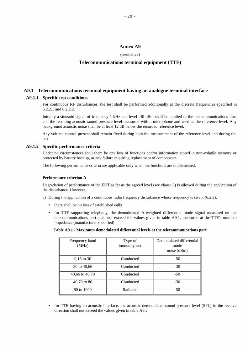
a) During the application of a continuous radio frequency disturbance whose frequency is swept (6.2.2):
• there shall be no loss of established calls
• for TTE supporting telephony, the demodulated A-weighted differential mode signal measured on thetelecommunications port shall not exceed the values given in table A9.1, measured at the TTE's nominalimpedance (manufacturer specified)
Table A9.1 - Maximum demodulated differential levels at the telecommunications port
Frequency band(MHz)
Type ofimmunity test
Demodulated differentialmode
noise (dBm)
0,15 to 30 Conducted -50
30 to 40,66 Conducted -30
40,66 to 40,70 Conducted -50
40,70 to 80 Conducted -30
80 to 1000 Radiated -50
• for TTE having an acoustic interface, the acoustic demodulated sound pressure level (SPL) in the receivedirection shall not exceed the values given in table A9.2
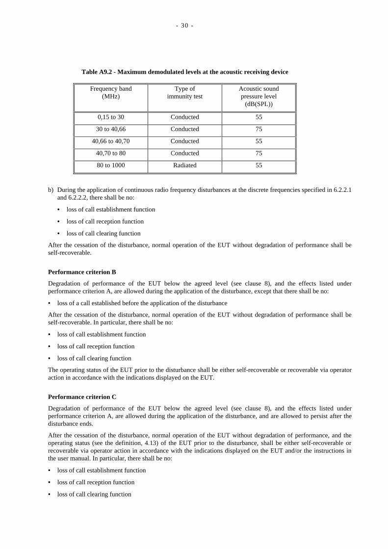
- 30 -
Table A9.2 - Maximum demodulated levels at the acoustic receiving device
Frequency band(MHz)
Type ofimmunity test
Acoustic soundpressure level
(dB(SPL))
0,15 to 30 Conducted 55
30 to 40,66 Conducted 75
40,66 to 40,70 Conducted 55
40,70 to 80 Conducted 75
80 to 1000 Radiated 55
b) During the application of continuous radio frequency disturbances at the discrete frequencies specified in 6.2.2.1and 6.2.2.2, there shall be no:
• loss of call establishment function
• loss of call reception function
• loss of call clearing function
After the cessation of the disturbance, normal operation of the EUT without degradation of performance shall beself-recoverable.
Performance criterion B
Degradation of performance of the EUT below the agreed level (see clause 8), and the effects listed underperformance criterion A, are allowed during the application of the disturbance, except that there shall be no:
• loss of a call established before the application of the disturbance
After the cessation of the disturbance, normal operation of the EUT without degradation of performance shall beself-recoverable. In particular, there shall be no:
• loss of call establishment function
• loss of call reception function
• loss of call clearing function
The operating status of the EUT prior to the disturbance shall be either self-recoverable or recoverable via operatoraction in accordance with the indications displayed on the EUT.
Performance criterion C
Degradation of performance of the EUT below the agreed level (see clause 8), and the effects listed underperformance criterion A, are allowed during the application of the disturbance, and are allowed to persist after thedisturbance ends.
After the cessation of the disturbance, normal operation of the EUT without degradation of performance, and theoperating status (see the definition, 4.13) of the EUT prior to the disturbance, shall be either self-recoverable orrecoverable via operator action in accordance with the indications displayed on the EUT and/or the instructions inthe user manual. In particular, there shall be no:
• loss of call establishment function
• loss of call reception function
• loss of call clearing function
- 31 -
A9.2 Telecommunications terminal equipment having a digital terminal interfaceA9.2.1 Specific test conditions
For continuous RF disturbances, the test shall be performed additionally at the discrete frequencies specified in6.2.2.1 and 6.2.2.2.
Initially a sinusoid signal of frequency 1 kHz and level -40 dBm shall be applied to the telecommunications line,and the resulting acoustic sound pressure level measured with a microphone and used as the reference level. Anybackground acoustic noise shall be at least 12 dB below the recorded reference level.
Any volume control present shall remain fixed during both the measurement of the reference level and during thetest.
A9.2.2 Specific performance criteriaUnder no circumstances shall there be any loss of functions and/or information stored in non-volatile memory orprotected by battery backup, or any failure requiring replacement of components.
The following performance criteria are applicable only when the functions are implemented.
Performance criterion A
Degradation of performance of the EUT as far as the agreed level (see clause 8) is allowed during the application ofthe disturbance. However,
a) During the application of a continuous radio frequency disturbance whose frequency is swept (6.2.2):
• there shall be no loss of established calls
• for TTE supporting telephony, the acoustic demodulated sound pressure level (SPL) in the receive directionshall not be greater than the values given in table A9.2
• for Basic Access ISDN interfaces providing telephony service, the digital channel in the assigned B channelof the TTE shall be idle code as defined for the applied digital to analogue conversion
b) During the application of a continuous radio frequency disturbance at the discrete frequencies specified in6.2.2.1 and 6.2.2.2,
• there shall be no loss of call establishment function
• there shall be no loss of call reception function
• there shall be no loss of call clearing function
• for TTE providing non-voice service, the time required for a transmission, as stated in the manufacturer'sspecification, shall not increase by more than 20% during the test
• for Primary Rate only, the number of losses of frame alignment shall be less than 10 within a test period of10 seconds. However, where it can be clearly established that a voice call is maintained throughout the test, itis not then required to evaluate the loss of frame alignment.
After the cessation of the disturbance, normal operation of the EUT without degradation of performance shall beself-recoverable.
Performance criterion B
Degradation of performance of the EUT below the agreed level (see clause 8), and the effects listed underperformance criterion A, are allowed during the application of the disturbance, except that there shall be no:
• loss of a call established before the application of the disturbance
After the cessation of the disturbance, normal operation of the EUT shall be self-recoverable. In particular, thereshall be no:
• loss of call establishment function
• loss of call reception function
- 32 -
• loss of call clearing function
The operating status of the EUT prior to the disturbance shall be either self-recoverable or recoverable via operatoraction in accordance with the indications displayed on the EUT.
Performance criterion C
Degradation of performance of the EUT below the agreed level (see clause 8), and the effects listed underperformance criterion A, are allowed during the application of the disturbance, and are allowed to persist after thedisturbance ends.
After the cessation of the disturbance, normal operation of the EUT without degradation of performance, and theoperating status (see the definition, 4.13) of the EUT prior to the disturbance, shall be either self-recoverable orrecoverable via operator action in accordance with the indications displayed on the EUT and/or the instructions inthe user manual. In particular, there shall be no:
• loss of call establishment function
• loss of call reception function
• loss of call clearing function


Printed copies can be ordered from:
ECMA114 Rue du RhôneCH-1204 GenevaSwitzerland
Fax: +41 22 849.60.01Internet: [email protected]
Files can be downloaded from our FTP site, ftp.ecma.ch, logging in as anonymous and giving your E-mail address aspassword. This Standard is available from library ECMA-ST as a compacted, self-expanding file in MSWord 6.0 format (fileE237-DOC.EXE) and as a compacted, self-expanding PostScript file (file E237-PSC.EXE). File E237-EXP.TXT gives a shortpresentation of the Standard.
The ECMA site can be reached also via a modem. The phone number is +41 22 735.33.29, modem settings are 8/n/1. Telnet(at ftp.ecma.ch) can also be used.
Our web site, http://www.ecma.ch, gives full information on ECMA, ECMA activities, ECMA Standards and TechnicalReports.

ECMA
114 Rue du RhôneCH-1204 GenevaSwitzerland
This Standard ECMA-237 is available free of charge in printed form and as a file.
See inside cover page for instructions