Embed Size (px)
Citation preview
w w w . a u t o s t e e l . o r g
David Reed, Tom Seel, Don BaskinChrysler LLC
Lightweight Body Section Targeting and Material Selection Process
David B. ReedSupervisor, BIW CoC
Thomas N. SeelManager Light Weight Design
Donald M. BaskinProduct Engineer
Axel VollmerCAD Engineer, MBtech
w w w . a u t o s t e e l . o r g
Outline of Topics
•BIW Structural Optimization Process
•Section Targeting Process
•Material Selection
Light Weight BodyStructural Optimization Process
w w w . a u t o s t e e l . o r g
Light Weight BodyStructural Optimization Process
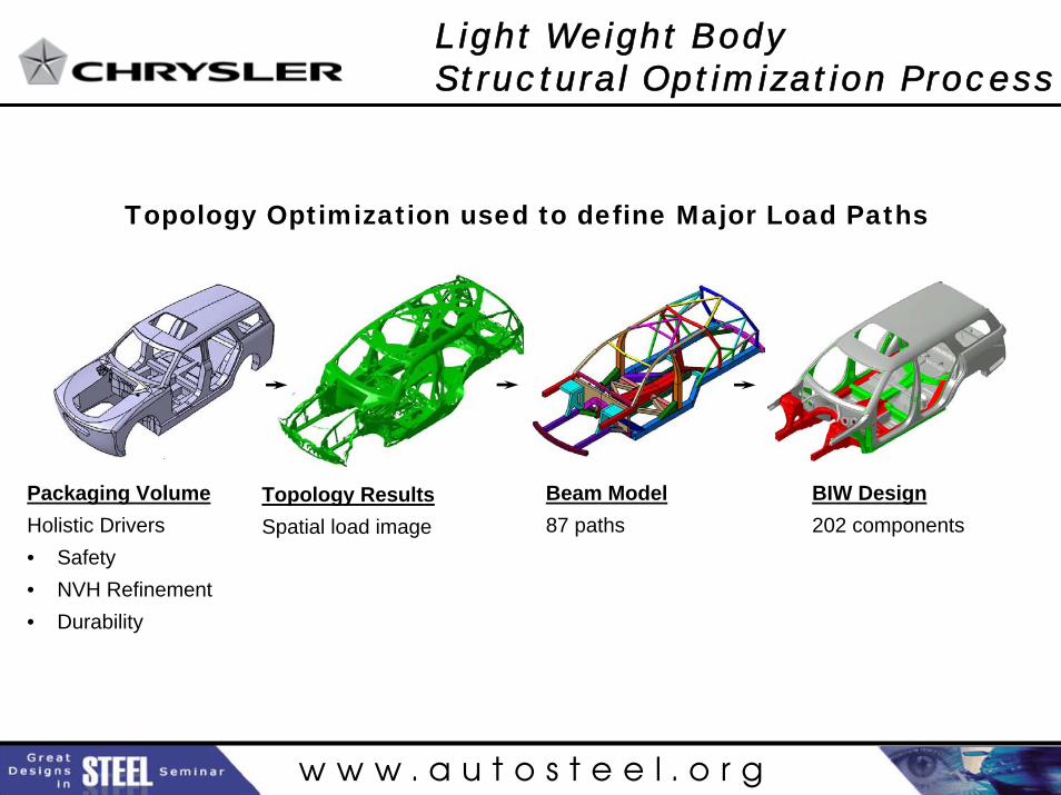
Topology Optimization used to define Major Load Paths
Packaging VolumeHolistic Drivers• Safety• NVH Refinement• Durability
Topology ResultsSpatial load image
Beam Model87 paths
BIW Design202 components
w w w . a u t o s t e e l . o r g
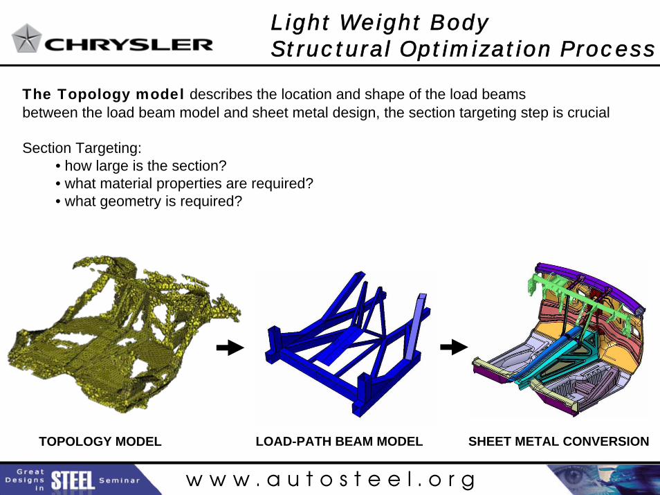
TOPOLOGY MODEL LOAD-PATH BEAM MODEL SHEET METAL CONVERSION
The Topology model describes the location and shape of the load beamsbetween the load beam model and sheet metal design, the section targeting step is crucial
Section Targeting: • how large is the section?• what material properties are required?• what geometry is required?
Light Weight BodyStructural Optimization Process
w w w . a u t o s t e e l . o r g
Section Targeting Process
•Define the loading condition
•Determine reaction forces and targets based on static equations and judgment of load path forces (bending, torsion, axial or combination)
•Investigate bending moments and balance the load in case the load path splits
•Use section cut to lay out cross section geometry and determine material grade and thickness
•Design for stiffness first, then up/down-yield strength accordingly
•Complete hand calculations prior to running full CAE analysis
Section Targeting Process
w w w . a u t o s t e e l . o r g
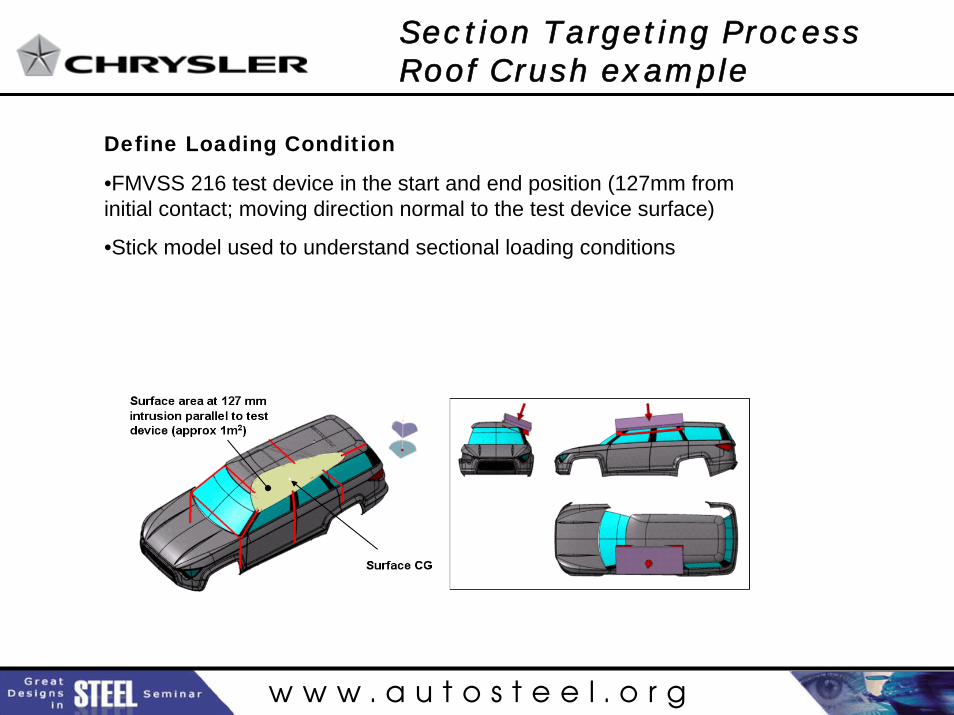
Define Loading Condition
•FMVSS 216 test device in the start and end position (127mm from initial contact; moving direction normal to the test device surface)
•Stick model used to understand sectional loading conditions
Section Targeting Process Roof Crush example
w w w . a u t o s t e e l . o r g
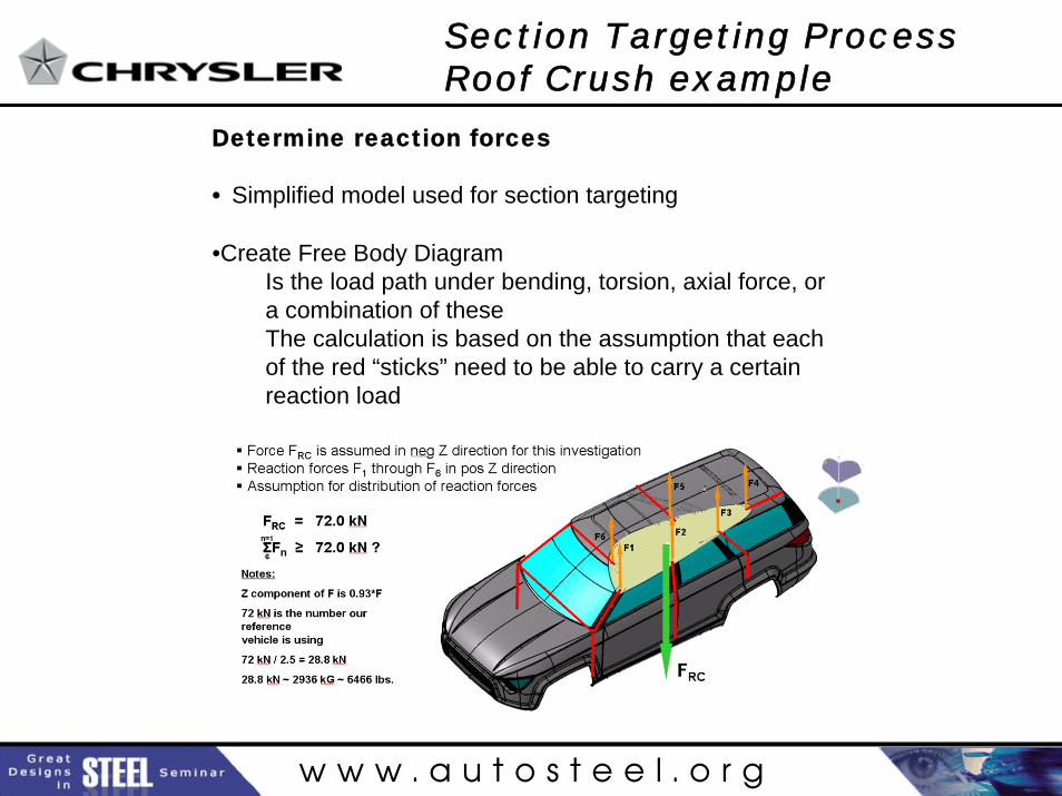
Determine reaction forces
• Simplified model used for section targeting
•Create Free Body DiagramIs the load path under bending, torsion, axial force, or a combination of theseThe calculation is based on the assumption that each of the red “sticks” need to be able to carry a certain reaction load
Section Targeting Process Roof Crush example
w w w . a u t o s t e e l . o r g
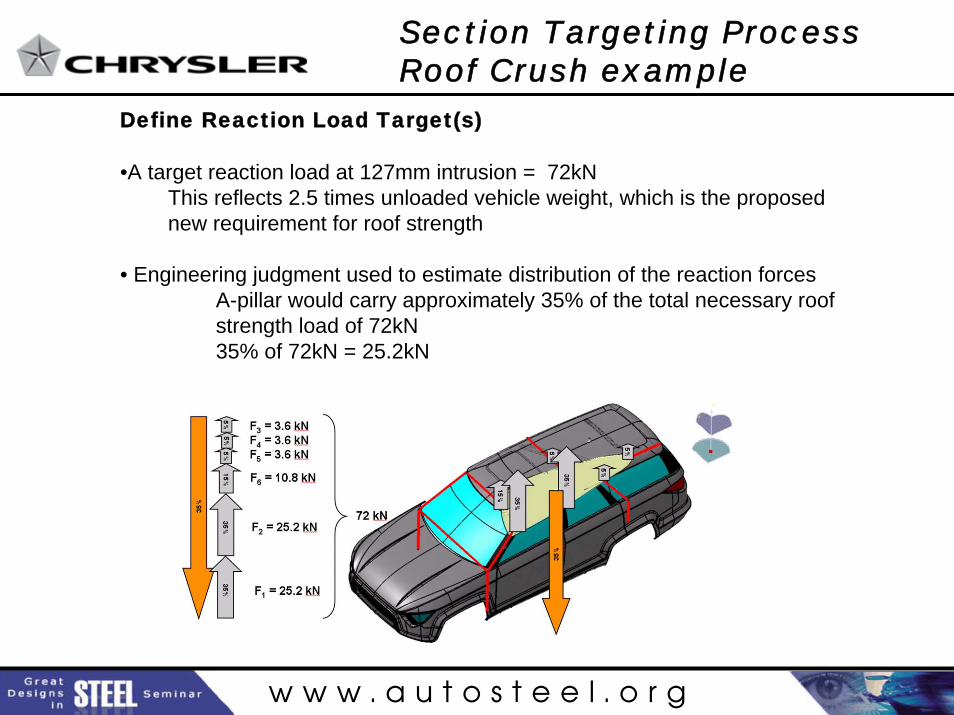
Define Reaction Load Target(s)
•A target reaction load at 127mm intrusion = 72kN This reflects 2.5 times unloaded vehicle weight, which is the proposed new requirement for roof strength
• Engineering judgment used to estimate distribution of the reaction forces A-pillar would carry approximately 35% of the total necessary roofstrength load of 72kN35% of 72kN = 25.2kN
Section Targeting Process Roof Crush example
w w w . a u t o s t e e l . o r g
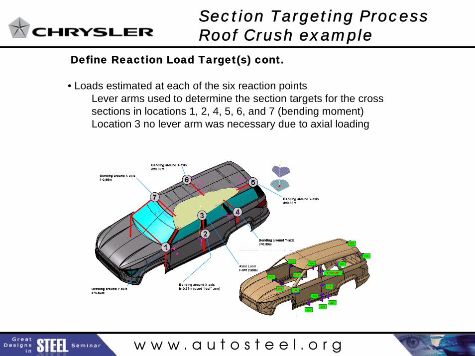
Define Reaction Load Target(s) cont.
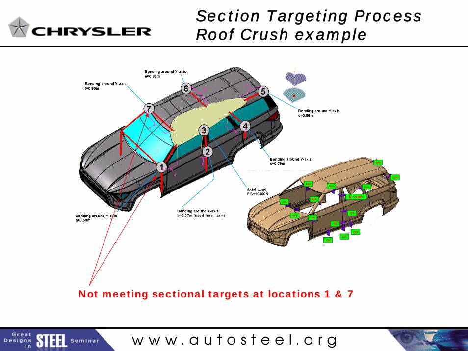
• Loads estimated at each of the six reaction points Lever arms used to determine the section targets for the cross sections in locations 1, 2, 4, 5, 6, and 7 (bending moment)Location 3 no lever arm was necessary due to axial loading
Section Targeting Process Roof Crush example
w w w . a u t o s t e e l . o r g
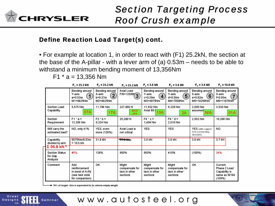
Define Reaction Load Target(s) cont.
• For example at location 1, in order to react with (F1) 25.2kN, the section at the base of the A-pillar - with a lever arm of (a) 0.53m – needs to be able to withstand a minimum bending moment of 13,356Nm
F1 * a = 13,356 Nm
Section Targeting Process Roof Crush example
w w w . a u t o s t e e l . o r g
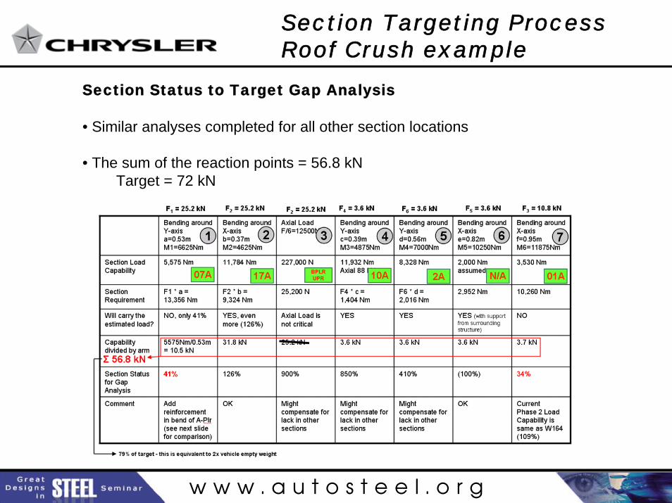
Section Status to Target Gap Analysis
• Similar analyses completed for all other section locations
• The sum of the reaction points = 56.8 kNTarget = 72 kN
Section Targeting Process Roof Crush example
w w w . a u t o s t e e l . o r g
Not meeting sectional targets at locations 1 & 7
Section Targeting Process Roof Crush example
w w w . a u t o s t e e l . o r g
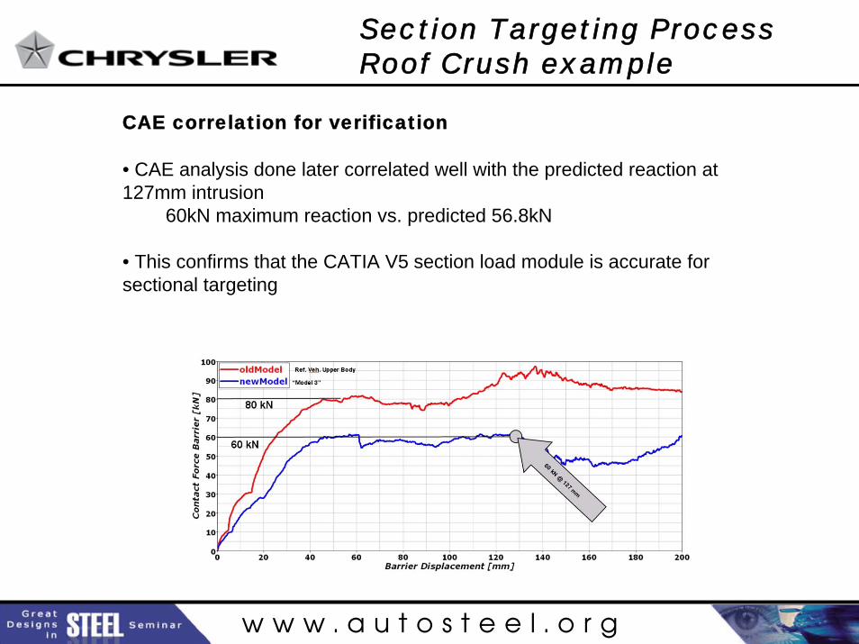
CAE correlation for verification
• CAE analysis done later correlated well with the predicted reaction at 127mm intrusion
60kN maximum reaction vs. predicted 56.8kN
• This confirms that the CATIA V5 section load module is accurate for sectional targeting
Section Targeting Process Roof Crush example
w w w . a u t o s t e e l . o r g
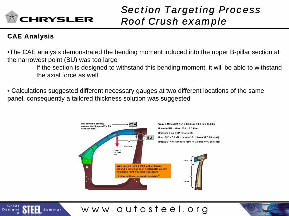
CAE Analysis
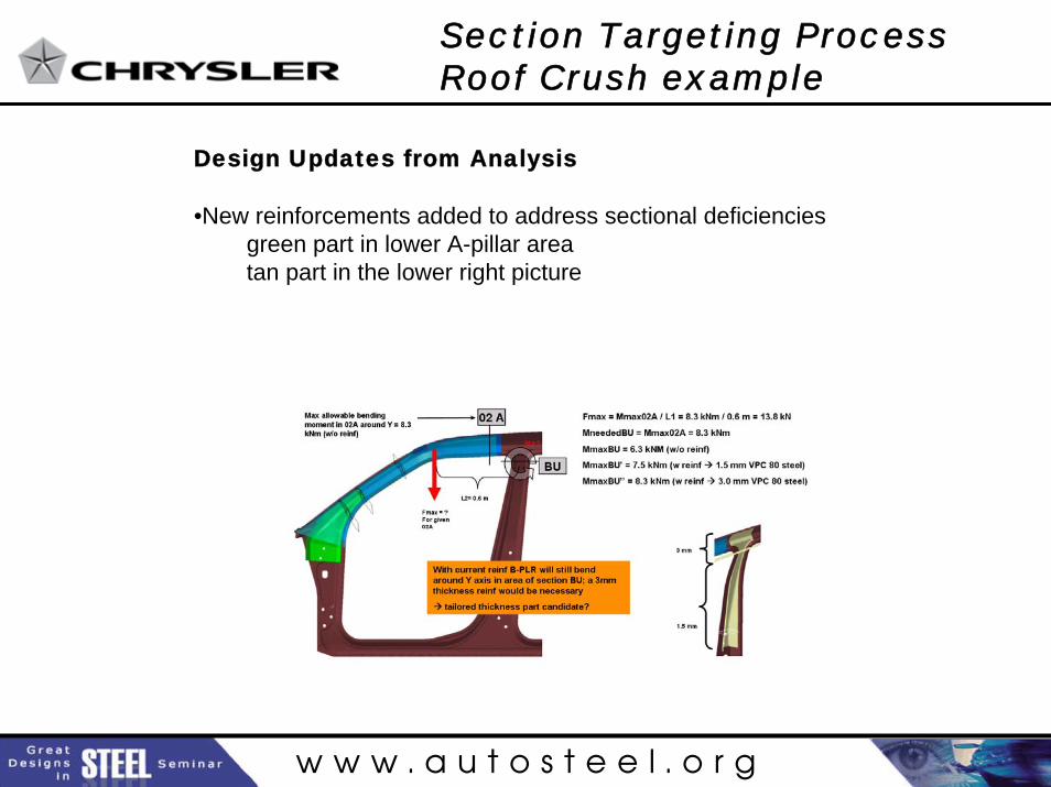
•The CAE analysis demonstrated the bending moment induced into the upper B-pillar section at the narrowest point (BU) was too large
If the section is designed to withstand this bending moment, it will be able to withstand the axial force as well
• Calculations suggested different necessary gauges at two different locations of the same panel, consequently a tailored thickness solution was suggested
Section Targeting Process Roof Crush example
w w w . a u t o s t e e l . o r g
Design Updates from Analysis
•New reinforcements added to address sectional deficienciesgreen part in lower A-pillar area tan part in the lower right picture
Section Targeting Process Roof Crush example
w w w . a u t o s t e e l . o r g
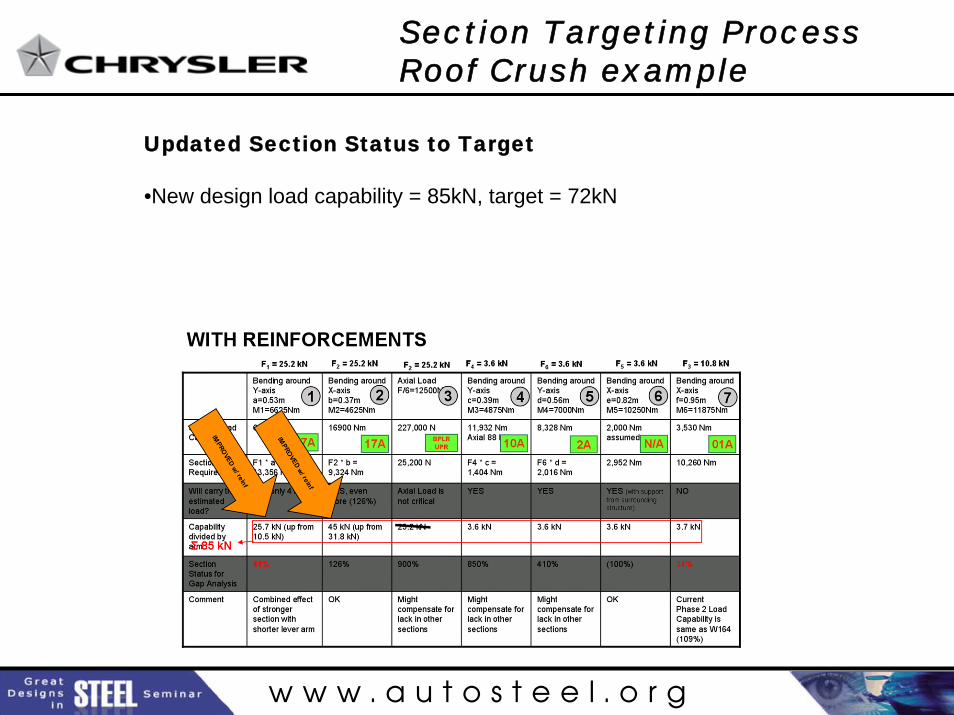
Updated Section Status to Target
•New design load capability = 85kN, target = 72kN
Section Targeting Process Roof Crush example
w w w . a u t o s t e e l . o r g
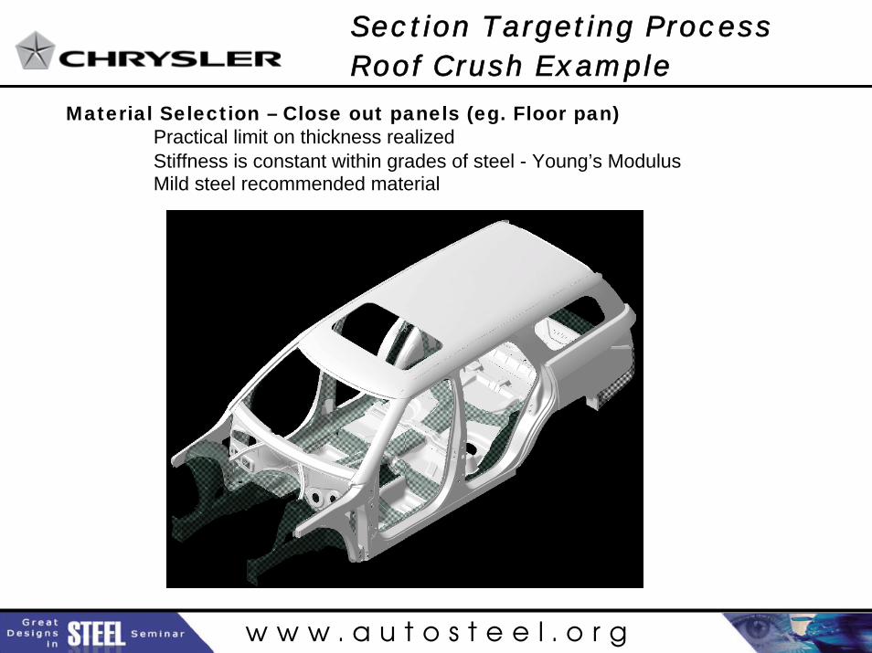
Material Selection – Close out panels (eg. Floor pan)Practical limit on thickness realizedStiffness is constant within grades of steel - Young’s ModulusMild steel recommended material
Section Targeting ProcessRoof Crush Example
w w w . a u t o s t e e l . o r g
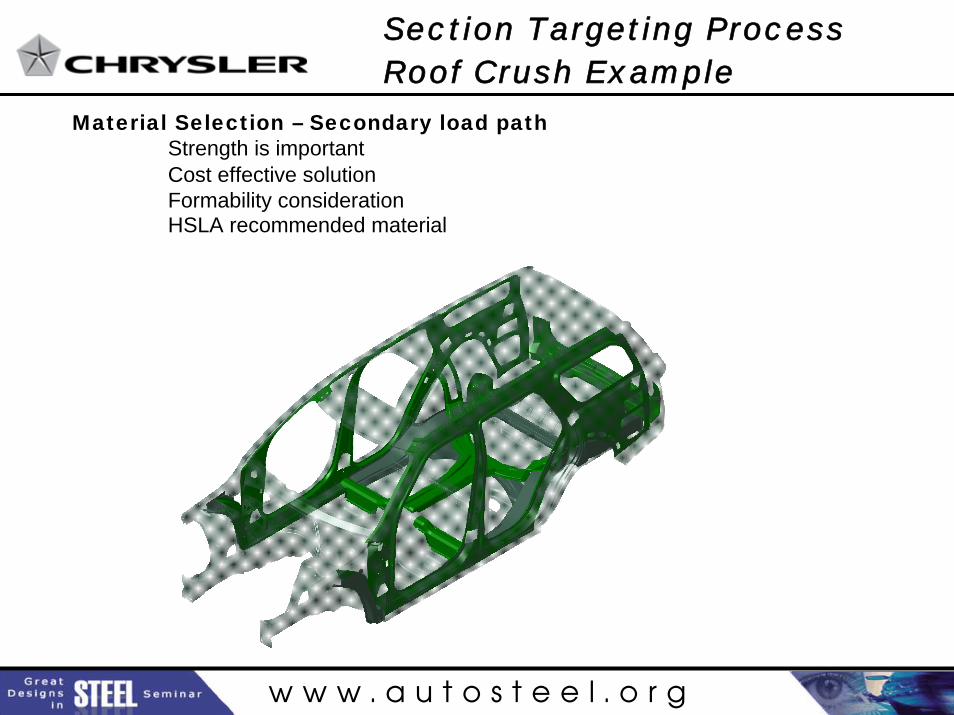
Material Selection – Secondary load pathStrength is important Cost effective solutionFormability considerationHSLA recommended material
Section Targeting ProcessRoof Crush Example
w w w . a u t o s t e e l . o r g
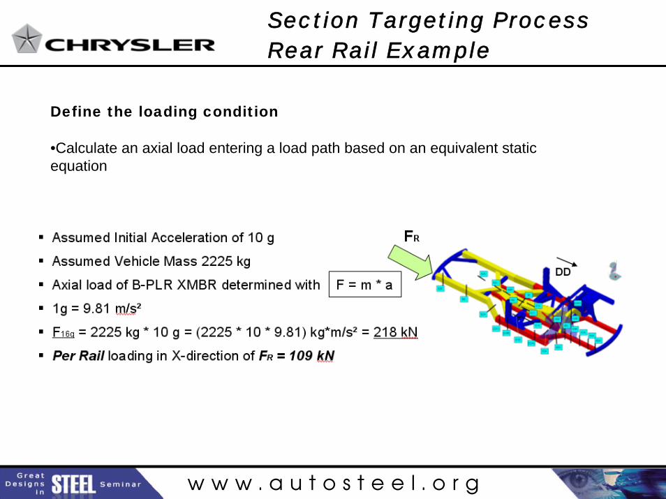
Define the loading condition
•Calculate an axial load entering a load path based on an equivalent static equation
Section Targeting ProcessRear Rail Example
w w w . a u t o s t e e l . o r g
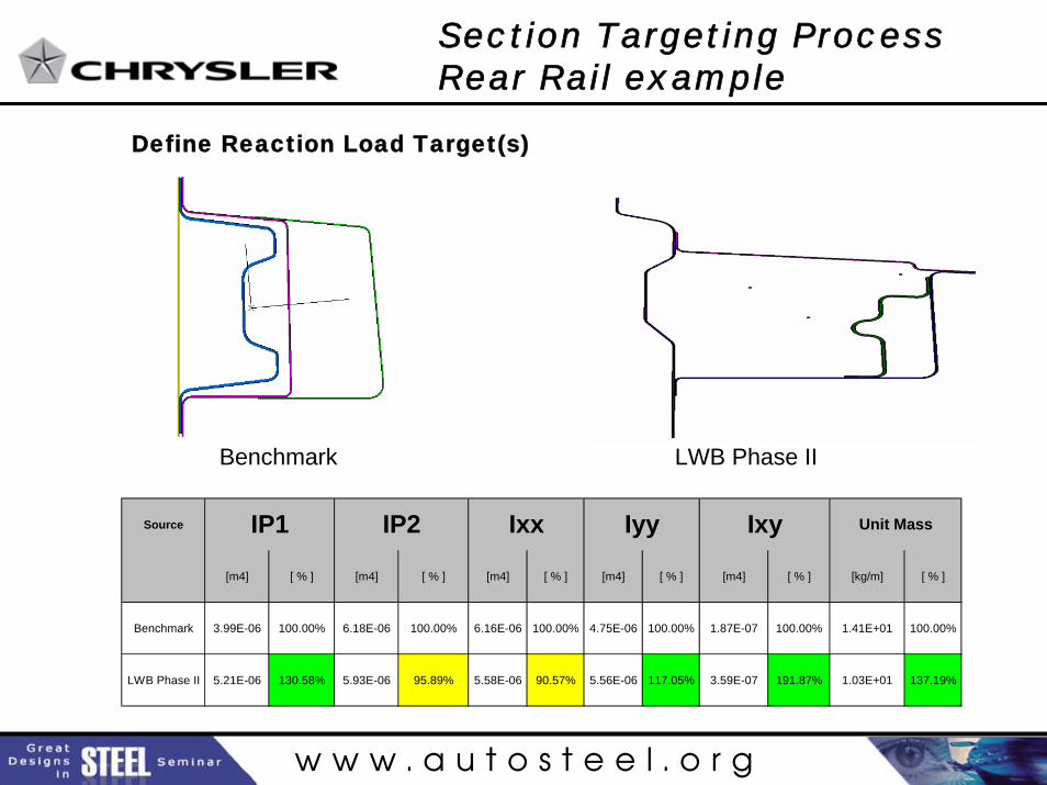
Define Reaction Load Target(s)
Section Targeting Process Rear Rail example
Benchmark LWB Phase II
Source
[m4] [ % ] [m4] [ % ] [m4] [ % ] [m4] [ % ] [m4] [ % ] [kg/m] [ % ]
Benchmark 3.99E-06 100.00% 6.18E-06 100.00% 6.16E-06 100.00% 4.75E-06 100.00% 1.87E-07 100.00% 1.41E+01 100.00%
LWB Phase II 5.21E-06 130.58% 5.93E-06 95.89% 5.58E-06 90.57% 5.56E-06 117.05% 3.59E-07 191.87% 1.03E+01 137.19%
Ixy Unit MassIP1 IP2 Ixx Iyy
w w w . a u t o s t e e l . o r g
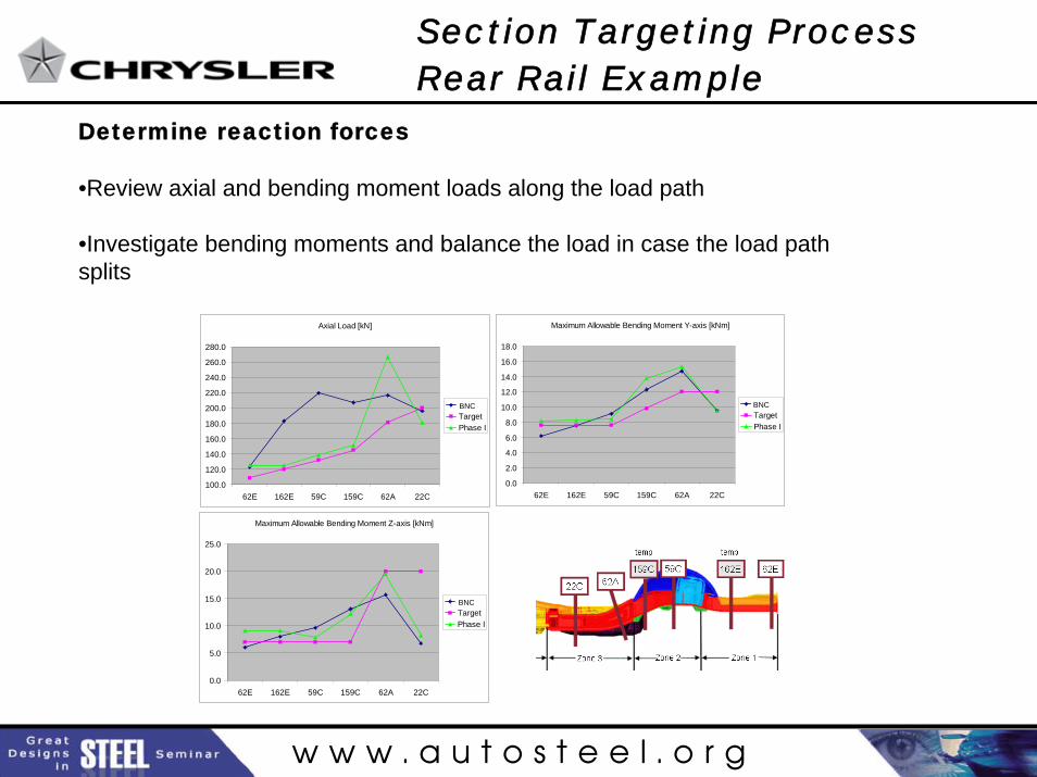
Determine reaction forces
•Review axial and bending moment loads along the load path
•Investigate bending moments and balance the load in case the load path splits
Section Targeting ProcessRear Rail Example
Maximum Allowable Bending Moment Z-axis [kNm]
0.0
5.0
10.0
15.0
20.0
25.0
62E 162E 59C 159C 62A 22C
W164TargetPhase I
Maximum Allowable Bending Moment Y-axis [kNm]
0.0
2.0
4.0
6.0
8.0
10.0
12.0
14.0
16.0
18.0
62E 162E 59C 159C 62A 22C
W164TargetPhase I
Axial Load [kN]
100.0
120.0
140.0
160.0
180.0
200.0
220.0
240.0
260.0
280.0
62E 162E 59C 159C 62A 22C
W164TargetPhase I
BNC BNC
BNC
w w w . a u t o s t e e l . o r g
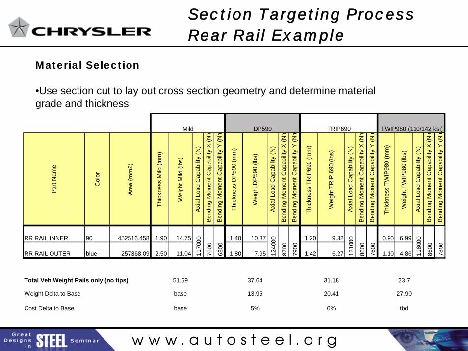
Material Selection
•Use section cut to lay out cross section geometry and determine material grade and thickness
Section Targeting ProcessRear Rail Example
Par
t Nam
e
Col
or
Area
(mm
2)
Thic
knes
s M
ild (m
m)
Wei
ght M
ild (l
bs)
Axia
l Loa
d C
apab
ility
(N)
Bend
ing
Mom
ent C
apab
ility
X (N
m
Bend
ing
Mom
ent C
apab
ility
Y (N
m
Thic
knes
s D
P590
(mm
)
Wei
ght D
P59
0 (lb
s)
Axia
l Loa
d C
apab
ility
(N)
Bend
ing
Mom
ent C
apab
ility
X (N
m
Bend
ing
Mom
ent C
apab
ility
Y (N
m
Thic
knes
s TR
IP69
0 (m
m)
Wei
ght T
RIP
690
(lbs
)
Axia
l Loa
d C
apab
ility
(N)
Bend
ing
Mom
ent C
apab
ility
X (N
m
Bend
ing
Mom
ent C
apab
ility
Y (N
m
Thic
knes
s TW
IP98
0 (m
m)
Wei
ght T
WIP
980
(lbs)
Axia
l Loa
d C
apab
ility
(N)
Bend
ing
Mom
ent C
apab
ility
X (N
m
Bend
ing
Mom
ent C
apab
ility
Y (N
m
RR RAIL INNER 90 452516.458 1.90 14.75 1.40 10.87 1.20 9.32 0.90 6.99
RR RAIL OUTER blue 257368.09 2.50 11.04 1.80 7.95 1.42 6.27 1.10 4.86
Total Veh Weight Rails only (no tips) 51.59 37.64 31.18 23.7
Weight Delta to Base base 13.95 20.41 27.90
Cost Delta to Base base 5% 0% tbd
Mild
1170
00
7600
6800
1210
00
8600
7600
7800
1180
00
8600
DP590 TRIP690 TWIP980 (110/142 ksi)
1240
00
8700
7900
w w w . a u t o s t e e l . o r g
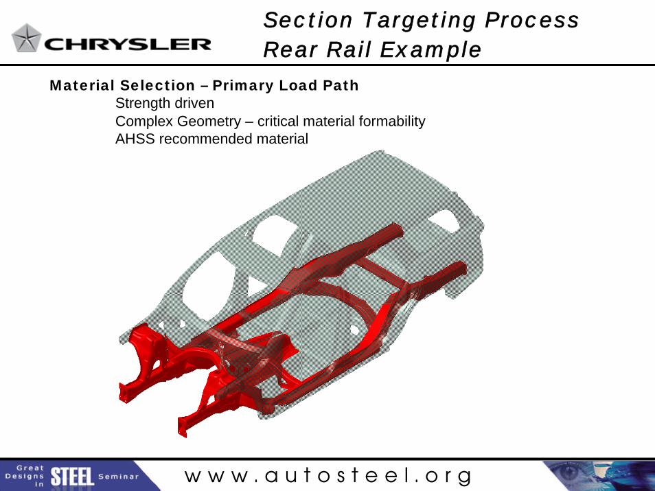
Material Selection – Primary Load PathStrength drivenComplex Geometry – critical material formabilityAHSS recommended material
Section Targeting ProcessRear Rail Example
w w w . a u t o s t e e l . o r g
Conclusions
• Topology Optimization is an effective tool to define the structural load paths
• Section targeting allows engineer to move from theoretical load paths into sheet metal design by a design for stiffness first, then up/down-yield strength accordingly strategy
• Hand calculations should be done prior to CAE analysis, saving weeks of time in sizing structural load paths and selecting material
Light Weight BodyStructural Optimization Process