Embed Size (px)
Citation preview
LIGHTNING PROTECTION MEASURES
As per IEC 62305–1/2010, protection measures may be adopted in order to reduce the risk according to the type of damage.
In order to evaluate whether or not lightning protection of a structure is needed, a risk assessment in accordance with the procedures contained in IEC 62305-2 shall be made. The following risks shall be taken into account;
R1 – Risk of loss or permanent injury to human lifeR2 – Risk of loss of services to the publicR3 – Risk of loss of cultural heritagesR4 – Risk of loss of Economic value (structure, its contents and loss of activity)
PROTECTION MEASURES TO REDUCE INJURY OF LIVING BEINGS BY ELECTRIC SHOCK
(i) Adequate insulation of exposed conductive parts.(ii) Equipotentialization by means of a meshed earthing system.(iii) Physical restrictions and warning notices.(iv) Lightning equipotential bonding.
Note:1 Equipotentialization and an increase of the contact resistance of the ground surface inside and outside the structure may reduce life hazards (See clause-8 of IEC 62305-3/2010)
Clause-8: Protection measures against touch voltages/Step voltages.(a) Under normal operation conditions, there are no persons within 3m from
the down conductors.(b) A system of at least 10 down conductors is employed.(c) Reduce contact resistance within 3m distance of down conductor by a
layer of insulating material. For example, asphalt of 5cm thickness or a layer of gravel 15cm thick. If none of these conditions is fulfilled, provide-(i) Insulation of the exposed down conductor at least using 3mm
XLPE.(ii) Equipotentialization by means of a meshed earth termination
system.(iii) Warning notices to minimize the probability of access to dangerous
area, within 3m of the down conductor.
PROTECTION MEASURES TO REDUCE PHYSICAL DAMAGE
This is achieved by LPS (Lightning Protection System) which include the following features;
(a) Air-Termination System(b) Down conductor system(c) Earth termination system(d) Lightning equipotential bonding (EB)
(e) Electrical insulation (and hence separation distance against the external LPS)
When LPS is installed, equipotentialization is a very important measure to reduce fire and explosion danger and life hazards. Firefighting appliances kept in the structure may reduce physical damage.
PROTECTION MEASURES TO REDUCE FAILURE OF ELECTRICAL AND ELECTRONICS SYSTEM
Surge protection measures (SPM) includes;
(a) Earthing and bonding measures(b) Magnetic shielding(c) Line routing(d) Isolating Interfaces(e) Coordinated SPD system
Protection measures listed above together form the overall lightning protection. The most suitable protection measures are given in IEC 62305-2.
LIGHTNING PROTECTION LEVELS
Four LPLs are introduced. For each LPL, a set of maximum and minimum lightning current parameters is fixed (LPL I to IV)The maximum values of lightning current parameters are used to design lightning protection components (Eg. Cross section of conductors, thickness of metal sheets, current capability of SPDs and Separation distance against dangerous sparking).The minimum values of lightning current amplitude for the different LPL are used to derive the Rolling Sphere Radius in order to define the Lightning Protection Zone (LPZ0B) which cannot be reached by direct strike.
RELATION BETWEEN LPL AND CLASS OF LPS (SEE IEC- 62305-1)
LPL CLASS OF LPSI III IIIII IIIIV IV
(Table-1)
Each class of LPS is characterized by the following;
(a) DATA DEPENDENT UPON THE CLASS OF LPS
(i) Lightning Parameters (see table 3 & 4 in IEC 62305-1/2010)(ii) Rolling Sphere radius, mesh size and protection angle (see 5.2.2)
(iii) Typical preferred distances between down conductors (see 5.3.3)(iv) Minimum length of earth electrode (see 5.4.2)(v) Separation distance against dangerous sparking (see 6.3)
(b) FACTORS NOT DEPENDENT UPON THE CLASS OF LPS
(i) Lightning equipotential bonding (see 6.2)(ii) Minimum thickness of metal sheets/pipes in air termination system(iii)LPS materials and conditions of use (see 5.5.1)(iv)Material configuration and minimum dimensions for air-termination
down conductors and earth terminations (see 5.6)(v) Minimum dimensions of connecting conductors (see 6.2.2)
The class of LPS shall be selected on the basis of a risk assessment (see IEC 62305-2)
LIGHTNING PROTECTION ZONE CONCEPT
The lightning protection zone concept allows planning, implementing and monitoring protection measures. All relevant devices, installations and systems must be reliably protected to an economically reasonable extent. To this end, a building is divided in zones with different risk potentials. Based on these zones, the required protection measures can be determined, in particular the lightning and surge protection devices and components.An EMC-based (EMC = electromagnetic compatibility) lightning protection zone concept includes external lighting protection (air-termination system, down conductor, earthing), equipotential bonding, spatial shielding and surge protection for the power supply and information technology system. The lightning protection zones are defined below.
LIGHTNING PROTECTION ZONES AND COMPREHENSIVE PROTECTION MEASURES
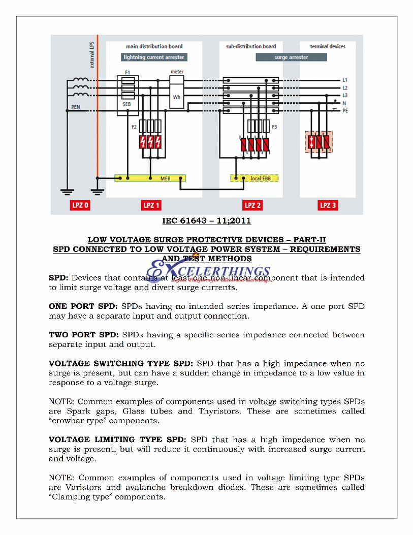
Surge protective devices are classified into lightning current arresters, surge arresters and combined arresters according to the requirements on their place of installation. Lightning current and combined arresters which are installed at the transition from LPZ 0A to 1 / LPZ 0A to 2 fulfil the most stringent requirements in terms of discharge capacity. These arresters must be capable of discharging partial lightning currents of 10/350 µs wave form several times without destruction, thus preventing injection of destructive partial lightning currents into the electrical installation of a building.
Surge arresters are installed at the transition from LPZ 0B to 1 and downstream of the lightning current arrester at the transition from LPZ 1 to 2 and higher. Their function is to mitigate the residual of the upstream protection stages and to limit the surges induced in the installation or generated in the installation.
The described lightning and surge protection measures at the boundaries of the lightning protection zones must be taken both for power supply and information technology systems. The consistent implementation of the described measures ensures permanent availability of a modern infrastructure.
DEFINITION OF LIGHTNING PROTECTION ZONES
LEMP protection of structures with electrical and electronic systems in accordance with IEC 62305-4 LPZ 0A Zone where the threat is due to the direct lightning flash and the full
lightning electromagnetic field. The internal systems may be subjected to full lightning surge current.
LPZ 0B Zone protected against direct lightning flashes but where the threat is the full lightning electromagnetic field. The internal systems may be subjected to partial lightning surge currents.
LPZ 1 Zone where the surge current is limited by current sharing and by SPDs at the boundary. Spatial shielding may attenuate the lightning electromagnetic field.
LPZ 2 Zone where the surge current may be further limited by current sharing and by additional SPDs at the boundary. Additional spatial shielding may be used to further attenuate the lightning electromagnetic field.
DESIGN OF THE LPS (EXTERNAL & INTERNAL)
The design of an LPS shall contain all the information necessary for correct and complete installation (See Annex E of IEC 62305-3)
EXTERNAL LPS
In most cases, the external LPS may be attached to the structure to be protected (non-isolated LPS)
An isolated external LPS should be considered when the thermal and explosive effects at the point of strike may cause damage to the structure or to the contents (see Annex E). Typical example includes structures with combustible covering, combustible walls and areas at risk of explosion and fire,
AIR TERMINATION SYSTEM
Air termination systems can be composed of any combination of the following elements;
(a) Rods (including free standing masts(b) Catenary wires(c) Meshed conductors
For all types of air terminals, only the real physical dimensions of the metal air-termination systems shall be used for determination of the volume protected.
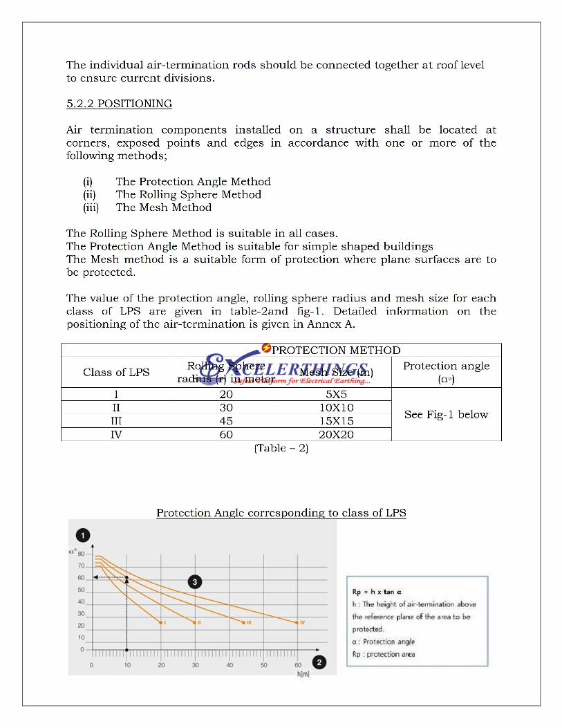
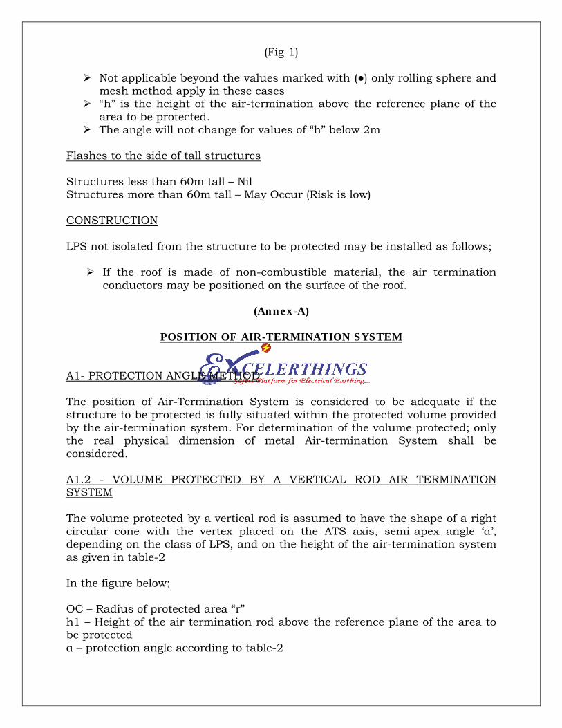
(Fig-1)
Not applicable beyond the values marked with (●) only rolling sphere and mesh method apply in these cases
“h” is the height of the air-termination above the reference plane of the area to be protected.
The angle will not change for values of “h” below 2m
Flashes to the side of tall structures
Structures less than 60m tall – NilStructures more than 60m tall – May Occur (Risk is low)
CONSTRUCTION
LPS not isolated from the structure to be protected may be installed as follows;
If the roof is made of non-combustible material, the air termination conductors may be positioned on the surface of the roof.
(Annex-A)
POSITION OF AIR-TERMINATION SYSTEM
A1- PROTECTION ANGLE METHOD
The position of Air-Termination System is considered to be adequate if the structure to be protected is fully situated within the protected volume provided by the air-termination system. For determination of the volume protected; only the real physical dimension of metal Air-termination System shall be considered.
A1.2 - VOLUME PROTECTED BY A VERTICAL ROD AIR TERMINATION SYSTEM
The volume protected by a vertical rod is assumed to have the shape of a right circular cone with the vertex placed on the ATS axis, semi-apex angle ‘α’, depending on the class of LPS, and on the height of the air-termination system as given in table-2
In the figure below;
OC – Radius of protected area “r”h1 – Height of the air termination rod above the reference plane of the area to be protectedα – protection angle according to table-2
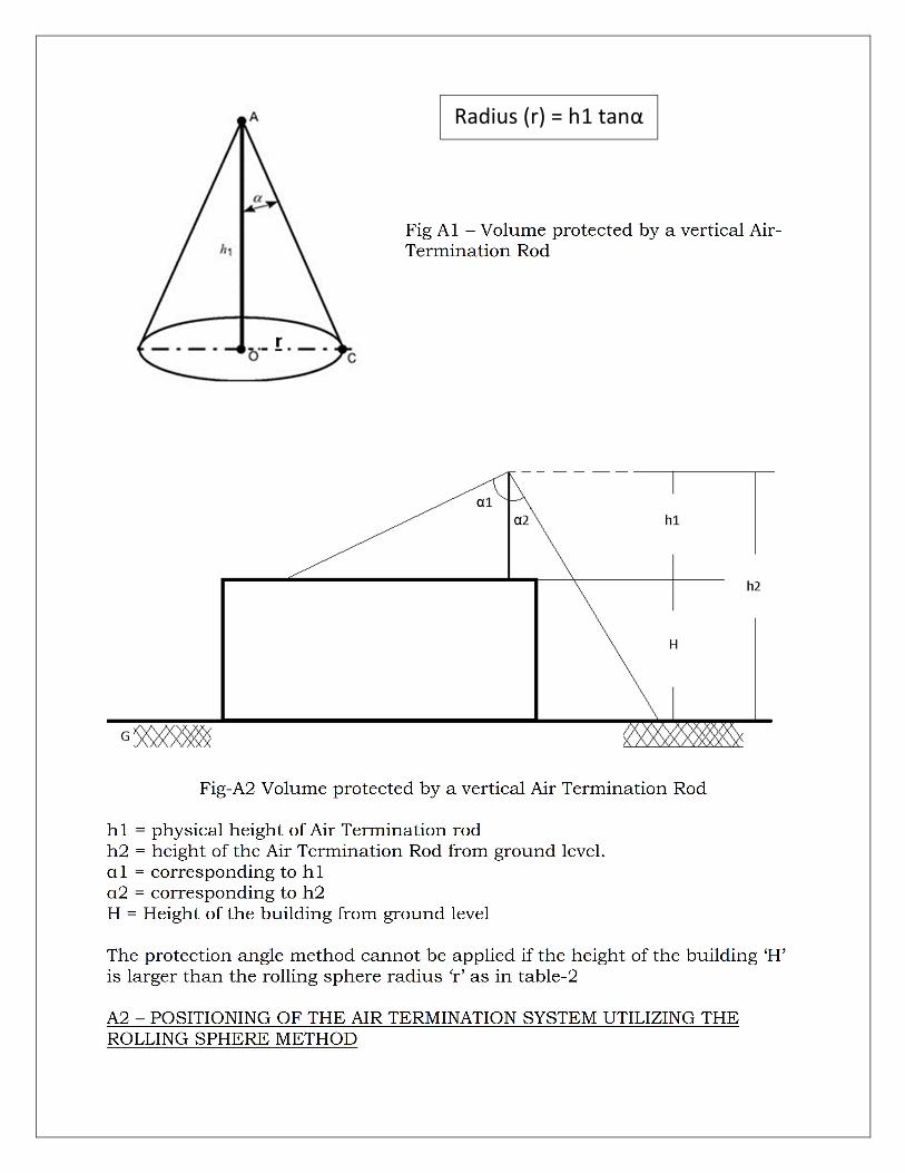
Radius (r) = h1 tanα
Air termination conductors and down conductors should be inter-connected by means of conductors at the roof level to provide sufficient current distribution over the down conductors.Conductors on roof and the connections of air termination rods may be fixed to the roof using both conductive or non-conductive spacers and fixtures. The conductors may also be positioned on the surface of a wall if the wall is made of non-combustible material. The fixing centers shall be minimum 1.0m apart.
For each non-isolated LPS, the number of down conductors shall be not less than two. A down conductor should be installed at each exposed corner of the structure, where this is possible.
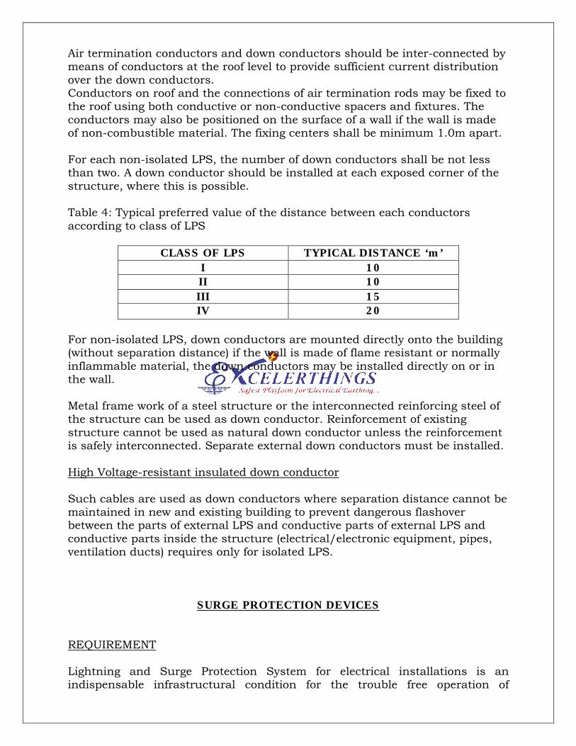
Table 4: Typical preferred value of the distance between each conductors according to class of LPS
CLASS OF LPS TYPICAL DISTANCE ‘m’I 10II 10III 15IV 20
For non-isolated LPS, down conductors are mounted directly onto the building (without separation distance) if the wall is made of flame resistant or normally inflammable material, the down conductors may be installed directly on or in the wall.
Metal frame work of a steel structure or the interconnected reinforcing steel of the structure can be used as down conductor. Reinforcement of existing structure cannot be used as natural down conductor unless the reinforcement is safely interconnected. Separate external down conductors must be installed.
High Voltage-resistant insulated down conductor
Such cables are used as down conductors where separation distance cannot be maintained in new and existing building to prevent dangerous flashover between the parts of external LPS and conductive parts of external LPS and conductive parts inside the structure (electrical/electronic equipment, pipes, ventilation ducts) requires only for isolated LPS.
SURGE PROTECTION DEVICES
REQUIREMENT
Lightning and Surge Protection System for electrical installations is an indispensable infrastructural condition for the trouble free operation of
µcomplex electrical and electronic systems. These concepts are according to IEC 62305 – 4 and the requirements are defined in IEC 60364 – 5 – 53.
CLASSIFICATION
SPDs used as part of the fixed building installations are classified into type-1,2 and 3 according to the requirements and stress on the places of installations and are tested to IEC 61643-11.
Type-1 SPDs
The highest requirement with respect to the discharge capacity are placed on Type – 1 SPDs. Those are used as part of the lightning and surge protection system at the boundary from LPZ0A to LPZ1 and higher. These surge protective devices must be capable of repeatedly carrying lightning Currents of 10/350µs wave form without destructing the equipment. These Type-1 SPDs are called Lightning Current Arresters. Their function is to prevent destructive partial Lightning currents from entering the electrical installations of a building.
Type-2 SPDs
Type – 2 SPDs are used at the transitions from LPZ0B to LPZ1 and higher or LPZ1 to LPZ2 and higher to protect against surges. The discharge capacity of about 10kA (8/20µs) are used.
Type-3 SPDs
These are the last link in the lightning and surge protection system for power supply systems to protect the terminal devices (transition from LPZ2 to LPZ3 and higher). The main function of the Type-3 surge protective device installed at point is to protect against over voltages arising between the conductors of an electrical system, in particular switching over voltages.
COMBINATION TYPE SPD: SPDs that incorporate both voltage switching components and voltage limiting components.
SHORT-CIRCUITING TYPE SPD: SPDs tested according to class-II tests which changes its characteristics to an intentional internal short circuit due to a surge current exceeding its nominal discharge current (In).
MODE OF PROTECTION OF AN SPD: An intended current path between terminal that contains protective components, e.g.: line to Line, Line to Earth, Line to Earth and Neutral to Earth.
1.2/50 Voltage Impulse: Voltage impulse with a nominal virtual front time of 1.2µs and a nominal time to half value of 50µs.
8/20 Current Impulse: Current Impulse with a nominal virtual front time of 8µs and nominal time to half value of 20µs.
CLASS-I TESTS: Tests carried out on the impulse discharge current Iimp
with an 8/20µs current impulse with a crest value equal to the crest value of Iimp, and with a 1.2/50 voltage impulse.
CLASS-II TESTS: Test carried out with the nominal discharge current (In) and the 1.2/50 voltage impulse.
CLASS-III TESTS: Tests carried out with the 1.2/50 voltage-8/20 current combination wave generator.
DECOUPLING NETWORK: An electrical circuit intended to prevent surge energy from being propagated to the power network during energized testing of SPDs (called back filter).
CHARACTERISTICS OF SPDs
MAX. CONTINUOUS OPERATING VOLTAGE (Uc) (Rated Voltage): This is the rms value of the max. voltage which may be applied to the terminals of the SPD during operation. Taking into account a 10% voltage tolerance for TN and TT systems, Uc is 253V for 230/400V systems.
LIGHTNING IMPULSE CURRENT (Iimp): This is a standardized impulse current curve with a 10/350µs waveform. Its parameters (peak value, charge,specific energy) simulate the stress caused by a natural lightning current. Lightning Impulse currents (10/350µs) apply to Type-1 SPDs. They must be able to discharge such lightning impulse currents several times without destructing the equipment.
NOMINAL DISCHARGE CURRENT (In): This is the peak value of the current (In) flowing through the surge protective devices (SPD). It has an 8/20µs impulse waveform and is rated for classifying the test of Type-2 SPDs.
TN-C SYSTEM
TN-C-S SYSTEM