Embed Size (px)
Citation preview

FLOODPROOFING NON-RESIDENTIAL BUILSINGS 4-1
Other Flood Protection Measures
C hapters 1, 2, and 3 focus on dry floodproofing, but other flood protection measures are also available to protect existing non-residential buildings from flooding. This chapter describes several other flood protection measures and the factors that should be considered when selecting one of these measures or
a combination of measures.
■■ The flood protection measures that are discussed in this chapter are:
■■ Permanent floodwalls and levees, which create a barrier between the building and floodwaters
■■ Wet floodproofing, which allows floodwaters to enter the building while using various techniques to minimize flood damage and protect critical systems and contents
■■ Floodproofing measures for electrical and mechanical utility systems that are difficult to dry floodproof
■■ Emergency measures for temporary protection (sandbags, temporary flood barriers, and flood wrapping systems)
As with the dry floodproofing measures discussed in the previous chapters, the flood protection measures in this chapter should be evaluated by a registered design professional to determine the design flood forces and which measures would be most effective.
4.1 Floodwalls and Levees Permanent floodwalls and levees are constructed barriers that provide flood protection to one or more build-ings. Unlike the dry floodproofing measures described in Chapter 3, which provide structural protection for shallow flood depths, floodwalls and levees can provide effective flood protection to buildings that experience flood levels of 4 feet or greater. However, if a floodwall or levee is breached or overtopped, then the barriers pro-vide no flood protection.
4.1.1 Floodwalls
A floodwall is a freestanding, permanent, engineered structure designed to prevent encroachment of flood-waters. Floodwalls, which are typically constructed of reinforced concrete or masonry, provide a barrier against
Warning
Floodwalls and levees are not permitted to address Substantial Improvement/Damage and do not bring new buildings into com-pliance with NFIP regulations unless they are accredited per 44 CFR § 65.10. Furthermore, the floodwalls and levees described in this chapter do not affect NFIP flood insurance rates or mandatory pur-chase requirements.
Additionally, NFIP regulations do not permit encroachments such as floodwalls and levees in a regulatory floodway unless hydrologic and hydraulic analyses demon-strate that the proposed floodwall or levee would not result in any increase in flood levels in the community during the base flood (44 CFR § 60.3(d)(3)).

4-2 FLOODPROOFING NON-RESIDENTIAL BUILDINGS
4 OTHER FLOOD PROTECTION MEASURES
inundation, protect structures from hydrostatic and hydrodynamic loads, and may deflect flood-borne debris and ice away from the building. When located in an area where ASCE 7 is referenced by adopted codes, flood-walls must be designed to resist ASCE 7 load combinations. Figure 4-1 shows a masonry floodwall.
Floodwalls are normally placed some distance from the building to avoid having to make structural modifica-tions to the building. Depending on the site topography, floodwalls may protect only the low side of the site (and must tie into high ground), or they may surround the site. Floodwalls that surround a site have open-ings that provide access to the site. The openings must be closed before the onset of a flood, which is done by installing engineered closure structures (see Figure 4-1). Site access is affected while the closure structures are in place.
When a building is protected by a floodwall, underground utilities that serve the building and run under the floodwall must be considered so the utilities do not become conduits that allow floodwaters to pass through or under the floodwall and into the building. See Section 4.1.1.2.
The following sections contain information on the most common types of floodwalls, the building and site characteristics to be considered when designing a floodwall, and the floodwall design process.
4.1.1.1 Types of Floodwalls
The most common types of floodwalls are gravity, cantilever, buttress, and counterfort (see Figure 4-2).
Figure 4-1. Typical masonry floodwall with engineered closures, which protected the Oak Grove Lutheran School in Fargo, ND, from flooding in 2001 (source: Flood Control America, LLC)

FLOODPROOFING NON-RESIDENTIAL BUILDINGS 4-3
4OTHER FLOOD PROTECTION MEASURES
4.1.1.1.1 Gravity Floodwalls
As the name implies, a gravity floodwall depends on its weight for structural stability. Structural stability is attained by effective positioning of the mass of the wall at its base, rather than by the weight of the retained materials (water or soil) on top of the wall foundations. A gravity floodwall resists overturning primarily because of the dead weight of the construction material (concrete or masonry); it is simply too heavy to be overturned by a lateral flood load.
Compared to the other types of floodwalls that are discussed, gravity floodwalls are relatively easy and straight-forward to construct. However, the primary disadvantage of gravity floodwalls is that they require massive amounts of material compared to the other floodwall types. As the height of a gravity floodwall increases and the amount of required material increases, the more cost-effective the other types of floodwalls become. Gravity walls are therefore most appropriate for low walls or lightly loaded walls. In addition, the sheer weight of the floodwalls required to resist flood forces can overload the bearing capacity of the supporting soils, which
Figure 4-2. Gravity, cantilever, buttress, and counterfort floodwalls

4-4 FLOODPROOFING NON-RESIDENTIAL BUILDINGS
4 OTHER FLOOD PROTECTION MEASURES
can make gravity floodwalls inappropriate when walls need to be relatively tall and the bearing soils are rela-tively weak.
4.1.1.1.2 Cantilever Floodwalls
Cantilever floodwalls are the most common type of floodwall because they are economical to design and construct. They use cantilever action to retain the mass behind the wall. Cantilever floodwalls are usually con-structed of reinforced concrete or concrete block with steel reinforcing bars embedded in the concrete core of the wall (see Figure 4-3).
Figure 4-3. Concrete cantilever floodwall reinforcement
Stability is achieved partially from the weight of the soil on the heel portion of the base and from the weight of the wall itself balanced by the lateral forces and overturning moments (see Figure 4-4). The footing is often constructed with a “key” to increase sliding resistance (see Figure 4-3).
Because a cantilever floodwall often also serves as a cantilever retaining wall, the floodwall must be designed to resist the load combinations in ASCE 7 or the loads in other accepted engineering standards. The design should take into account buoyancy effects that reduce the submerged weight of the floodwall and the reduced bearing capacity of the soils that support the wall. Backfill may be placed along the side of the wall exposed to flooding to keep water away from the wall during flooding conditions.
Similar to the gravity floodwall, as the flood elevation increases and the required materials and cost of the can-tilevered floodwall increase, the more cost-effective the alternative types of floodwalls may become.

FLOODPROOFING NON-RESIDENTIAL BUILDINGS 4-5
4OTHER FLOOD PROTECTION MEASURES
4.1.1.1.3 Buttress and Counterfort Floodwalls
The only difference between a buttress and counterfort floodwall is that the transverse support wall is on oppo-site sides (see Figure 4-2). In a buttressed floodwall, the transverse support wall is on the heel side, opposite the retained materials, and in a counterfort wall, the transverse support wall is on the toe side. Counterfort floodwalls are more widely used than buttressed floodwalls because their transverse support walls are hidden under the retained material (water or soil), whereas buttress floodwalls occupy what could otherwise be usable space in front of the wall.
A counterfort floodwall is similar to a cantilever floodwall except that a counterfort can be used when the can-tilever would be long or when very high pressures would be exerted behind the wall. Counterfort walls include intermediate transverse support bracing designed and built at intervals along the wall to allow for a more eco-nomical wall design. Counterfort walls are generally cost-effective for walls higher than 20 feet.
4.1.1.2 Building and Site Considerations in Floodwall Design
Designing a floodwall requires detailed information about the existing building and site. Key information includes:
■■ Surveyed lowest point of entry
■■ Topographic and utilities survey
■■ Identified flood hazards
■■ Soil type
■■ Local building requirements
■■ Owner preferences
Figure 4-4. Stability of a cantilever floodwall

4-6 FLOODPROOFING NON-RESIDENTIAL BUILDINGS
4 OTHER FLOOD PROTECTION MEASURES
After this information has been collected, the designer must assess the existing building and site conditions, as follows:
■■ Existing building foundation conditions. Existing building foundation conditions may affect the floodwall design directly. For example, evidence of seepage or cracking in foundation walls may indicate the need to relieve hydrostatic pressure on the foundation as part of the floodwall design.
■■ Soil type. The type of soil surrounding the existing building is a key consideration in floodwall design. In general, the more cohesive soils (e.g., silty sands, clays) have lower permeability and reduced seepage potential, and can simplify floodwall drainage design. Less cohesive soils, such as clean sands or gravels, tend to have higher permeability and increased seepage potential, which must be accounted for in the drainage design. More cohesive soils tend to have lower bearing capacity and frictional resistance that may require larger floodwall footings than those on less cohesive soils.
■■ Potential for seepage under the floodwall. A floodwall may not reduce the hydrostatic pressures against a below-grade foundation. Seepage under the floodwall and the natural capillary action of the soil layer may result in a water level inside the floodwall that is equal to or above grade. The water level inside the floodwall increases as the depth of flooding outside the floodwall increases and may compromise floodwall effectiveness for long-duration events if not addressed.
■■ The potential for seepage under the floodwall can be relieved by installing a foundation drainage system (drainage tile and sump pump) at the footing level and/or by extending the distance from the foundation to the floodwall. Seepage pressures can also be decreased by placing backfill against the floodwall to extend the point where floodwaters submerge the soil or by installing a sheet pile or cement curtain cutoff wall below the floodwall foundation surrounding the existing structure. Computing the proper spacing between the structure and floodwall foundation, backfill soils, or cutoff walls required to address seepage pressure is complex and should be done by an experienced geotechnical engineer.
■■ Number and size of floodwall openings. The number and size of floodwall openings have a direct impact not only on the floodwall design but also on the operation of the existing building. Floodwalls with fewer and smaller openings are simpler to design and require less warning time to protect with floodwall closures, but the reduced number of openings can limit site access, hampering the ability of the existing building to function efficiently. Designers can consider passive floodwall opening systems that minimize the need for human intervention. Designers must therefore discuss the floodwall openings and access/egress issues with owners to understand the needs and level of disruption to be expected to facility operations.
■■ Utility penetrations through or under the floodwall. Utilities that penetrate the floodwall or run under the floodwall may become conduits that allow floodwaters to enter the area protected by the floodwall. Utilities should be sealed, and because sealing is rarely 100 percent effective, provisions to collect and dispose of seepage that flows through underground utilities should be installed.
Warning
Flood duration is a critical consideration in the design of floodwall seepage control measures. The longer the duration (i.e., the longer floodwaters are in contact with the floodwall), the greater the potential for seepage and the greater the need for seep-age control measures such as backfill or cutoff walls.

FLOODPROOFING NON-RESIDENTIAL BUILDINGS 4-7
4OTHER FLOOD PROTECTION MEASURES
Best Practice – Floodwall System with Passive Floodgates Protects Two Hospitals
Lourdes Hospital in Binghamton, NY, is in the 100-year floodplain of the Susquehanna River. Flooding in 2006 forced the hospital to close for 2 weeks and caused $20 million in damage (FEMA 2011a). Relocating the hospital was not feasible, but it was determined that a floodwall system would provide the necessary protection. The system was constructed for an estimated $7 million using funds from FEMA and New York State. The floodwall, which protects the hospital to a 500-year flood elevation, consists of a concrete T-wall and passive floodgates at each of the 11 entry points. The gates automati-cally deploy during a flood, triggered by the hydrostatic pressure of the rising floodwaters. When the floodwaters recede, the gates lower to their original open position. The floodwall was completed in 2010.
In 2011, Tropical Storm Lee swept through Binghamton depositing 7.5 inches of rain in a single day. The Susquehanna River crested at 25.7 feet before receding (NOAA 2011). Despite the record rainfall, the hospital remained fully operational and experienced no flooding (see Figures 4-5 and 4-6).
Columbus Regional Hospital in Columbus, IN, was closed for 6 months in 2008 because of flooding. The flooding forced the evacuation of 157 patients, knocked out primary and emergency electrical sys-tems, and caused $180 million in damage (Columbus Regional Hospital 2012). Relocating the hospital was not feasible because of cost. FEMA and the hospital staff determined that a floodwall would be the best way to provide flood protection. Construction began in June 2011 and was completed in April 2012. The floodwall was funded by the FEMA Public Assistance Program, 406 Mitigation Program. The encir-cling 2,400-foot floodwall is 2 feet higher than the 100-year flood elevation and incorporates 15 passive floodgates (FEMA 2012c). The hospital has also strengthened its Flood Emergency Response Plan. Hospital officials are more involved with community management now and remain aware of weather conditions (see Figures 4-7 and 4-8).
Figure 4-5. Floodwall successfully safeguards Lourdes Hospital from Tropical Storm Lee flooding (source: FloodBreak)
Figure 4-6 Aerial view showing effective protection of Lourdes Hospital from flooding as a result of Tropical Storm Lee

4-8 FLOODPROOFING NON-RESIDENTIAL BUILDINGS
4 OTHER FLOOD PROTECTION MEASURES
4.1.1.3 Floodwall Design Process
Floodwall design depends primarily on the type of flooding expected at the building site. High water levels and velocities can exert significant hydrostatic and hydrodynamic forces that must be accounted for in the floodwall design.
The design of any type of floodwall must address the following three concerns:
■■ Ability of the wall to resist external loads and hold back floodwater
■■ Sufficiency of floodwall closure strength and stiffness to resist the calculated stresses
■■ Ability of surrounding soils to resist scour and erosion
Most non-residential floodwalls are engineered to flood depths of 6 or 7 feet above existing grade. A minimum of 1 foot of freeboard above the flood protection level is recommended. Tall floodwalls (taller than 10 feet) can be expensive to construct and maintain and may require additional land for grading and drainage.
Designers should follow the eight-step process shown in Figure 4-9 and develop specifications for appurte-nances such as drainage systems, waterproof materials to stop seepage and leakage, and miscellaneous details to meet site and owner preferences.
Important issues to be considered in the eight-step floodwall design process are as follows:
■■ When determining the wall height and footing depth based on site and design flood conditions (Step 1 in Figure 4-9), remember to include freeboard where appropriate and when required by local codes or regulations.
■■ Use load combinations specified by ASCE 7 to calculate lateral and vertical forces acting on the wall (Step 3 in Figure 4-9).
■■ If the calculated factors of safety against sliding, overturning, or bearing capacity failure of the wall are insufficient (Steps 4, 5, and 7 in Figure 4-9), revise wall dimensions and repeat analyses based on the corrected dimensions.
Figure 4-7. Floodwaters surround Columbus Regional Hospital in 2008
Figure 4-8 Columbus Regional Hospital schematic of floodwall plan

FLOODPROOFING NON-RESIDENTIAL BUILDINGS 4-9
4OTHER FLOOD PROTECTION MEASURES
The floodwall design process is iterative—the initial design is based on experience and successful designs, checked against design loads and conditions, and revised as necessary until all requirements are satisfied by the design.
Figure 4-9. Floodwall design process

4-10 FLOODPROOFING NON-RESIDENTIAL BUILDINGS
4 OTHER FLOOD PROTECTION MEASURES
4.1.2 Levees
Unlike floodwalls, levees are not made of manmade materials but rather compacted soil. Levees are more commonly used to protect large areas such as agricultural facilities. However, given their relative cost and the amount of land required, levees are a less common flood-mitigation measure than many of the other flood protection options presented in this manual. The following sections provide basic details on levee construction considerations and design.
4.1.2.1 Building and Site Considerations in Levee Design
Designing a levee requires collecting information about the existing building(s) to be protected and the sur-rounding site, including the surveyed lowest point of entry, topographic and utilities surveys, flood hazard identification, soil type, local building requirements, and owner preferences. After this information has been collected, the designer must assess whether certain con-ditions exist before a levee can be considered a viable floodproofing option. The key conditions to consider before proceeding are listed below.
■■ Property area. Levees typically require a significant amount of vacant land surrounding the area to be protected and are not suitable for densely developed areas.
■■ Topography. A significant portion of the cost associated with the construction of a levee hinges on the amount of fill material needed. If the natural topography around the area to be protected is such that only one or two sides of the area need to be protected, a levee may be more feasible and economical.
■■ Suitable soil availability. Relatively impermeable soils that will support the levee foundation and act as suitable impervious fill materials must be readily available to address concerns of stability and seepage. ASTM International (ASTM) defines impermeable soils (e.g., high-plasticity clays, low-plasticity clays, clayey sands) in ASTM D2487, Standard Practice for Classification of Soils for Engineering Purposes (Unified Soil Classification System) (ASTM 2011).
■■ Regulatory requirements. Relevant Federal and State laws and regulations and local ordinances must be reviewed. Coordination with Federal, State, and local officials may be necessary to determine whether levee construction is permissible, restricted, or prohibited. Also, NFIP regulations restrict levee construction in a FEMA-designated floodway, which is the main portion of a stream or watercourse that conveys flow during the base flood.
■■ Flood depth and velocity. Levees become increasingly more expensive to design and construct as flood depths exceed 7 feet because of material costs and space requirements. Additionally, if flood velocities exceed 8 feet per second (ft/sec), the increased cost of protecting against the scour potential may require considering a different retrofit measure. Finally, flood depths and velocities should be checked to ensure that the levee will not result in increased flood hazards upstream. In many cases, the local floodplain regulations may require an analysis of the proposed modification to the floodplain.
Special Note
For more information on levee design and construction, see Chapter 5F of FEMA P-259.

FLOODPROOFING NON-RESIDENTIAL BUILDINGS 4-11
4OTHER FLOOD PROTECTION MEASURES
■■ Seepage potential. Seepage under a levee and the natural capillary action of the soil layer may result in a water level inside the levee that is equal to or above grade and may compromise the levee effectiveness. This condition can be relieved by using an impervious core that extends to the bottom of the inspection trench, installing a drainage toe, and/or extending the distance from the foundation to the levee.
4.1.2.2 Basic Levee Design Parameters
The basic parameters described below help to control levee design costs while providing a conservative design in general accordance with the USACE guidance. The parameters pertain to the design and construction of localized levees for a maximum flood depth of 7 feet. Slope stability analysis and calculation of seepage rates are not addressed. The recommended side slopes are based on experience to satisfy requirements for stability, seepage control, and maintenance. The shear strength of suitable impervious soils compacted to at least 95 per-cent of the Standard Laboratory density as determined in ASTM D698, Standard Test Methods for Laboratory Compaction Characteristics of Soil Using Standard Effort (ASTM 2012), should be adequate to ensure stability of such low levees without the need for laboratory or field testing or extensive calculations.
The basic parameters for crest width and levee side slopes are defined below and illustrated in Figure 4-10. In combination with the toe drainage trench and the cutoff effect provided by backfilling of the inspection trench (Section 4.1.2.3), these parameters should provide sufficient control of seepage and may not require complex analyses.
■■ Maximum settled levee height of 8 to 10 feet. Recommended as the practical limit of levees that protect one or more individual structures based on available space and material costs.
■■ Minimum levee crest width of 10 to 12 feet. Recommended to minimize seepage concerns and allow for ease of construction, vehicle access, and maintenance.
■■ Levee floodwater side slope of 1 vertical to 2.5 horizontal. Recommended to minimize the erosion and scour potential, provide adequate stability under all conditions (including rapid drawdown situations), and facilitate maintenance.
■■ Levee land side slope. May vary based on the levee material. If the material is clayey, a land side slope of 1 vertical to 3 horizontal is acceptable. If the levee material is sandy, a flatter slope of 1 vertical to 5 horizontal is recommended to provide a lower seepage gradient.
Warning
The design parameters for a typical non-residential levee as shown in Figure 4-6 are based on guidance from the USACE and other sources and are intended to be conservative. Alternate parameters for a specific site may be developed by a geo-technical engineer qualified in levee design.
Warning
Duration of flooding is a critical consid-eration in the design of levee seepage control measures. The longer the duration of flooding (i.e., the longer floodwaters are in contact with the levee), the greater the potential for seepage, and the greater the need for seepage control measures such as cutoffs, drainage toes, and impervious cores.

4-12 FLOODPROOFING NON-RESIDENTIAL BUILDINGS
4 OTHER FLOOD PROTECTION MEASURES
■■ 1 foot of freeboard. Recommended to provide a margin of safety against overtopping and to allow for the effects of wave and wind action. Wave and wind forces create an additional threat by raising the height of the floodwaters.
Figure 4-10. Levee design parameters for a typical non-residential levee
In addition to these design parameters, considerations must be made for the maintenance of the levee. Maintenance must be completed on a regular basis. The maintenance program should include:
■■ A collection or sand trench on the inward or landward toe of the levee to collect any seepage that may occur and to act as a place to collect interior rainfall runoff. See Figure 4-8 above.
■■ A levee meant to be in place permanently should include an inspection/cutoff trench. This trench serves many purposes, including tying the levee structure into natural ground; as a means of identifying various utility lines that may be passing underneath the levee and need relocating; as a means of identifying burrowing animal passages; and, when backfilled with an impervious soil, as a means of stopping seepage underneath the levee.
■■ Drainage and runoff inside the levee must be taken into consideration. The above sand drainage toe facilitates the collection of interior runoff. When directed into sumps along the toe of the levee, the collected runoff can be pumped out of the protected area.
■■ Burrowing animals often favor levee embankments as a place for their dens and borrows. Some of the worst offenders are muskrats and woodchucks or ground hogs. These burrows afford a ready means for floodwaters to pass through the levee structure. Such burrowing will eventually lead to a weakening of the levee and possible failure.
■■ Trees and large shrubs should not be allowed to grow on a levee. If they are removed or die at a later time, their root systems decay and provide weak areas in the levee that can also lead to failure.
■■ Utility lines, such as electrical conduits or sewers, should not pass through a levee. Seepage along the exterior side of these lines can lead to what is known as “piping,” where fine soil particles are washed away in the interior of the levee. As this process continues, larger and larger particles are dislodged, again leading to potential levee failure.

FLOODPROOFING NON-RESIDENTIAL BUILDINGS 4-13
4OTHER FLOOD PROTECTION MEASURES
■■ The flood or water side of the levee should be protected with the appropriate size of rip-rap if flood velocities are sufficiently high to warrant it. Check with a qualified local engineer to determine the need and size of rip-rap.
■■ Barriers such as levees may not be permitted by regulatory agencies because of their potential adverse impact on flood stages. They should be designed and planned by a qualified engineer.
■■ If water overtops a levee, it will likely fail at that point unless heavily armored. Keep in mind that once a levee begins to fail, the area meant to be protected will flood quickly.
■■ Constructing behind a levee system creates residual risk as a result of the potential of failure of the levee structure.
4.1.2.3 Levee Design Process
Designing levees involves sizing the levee properly and developing the specifications for appurtenances such as drainage systems, impervious fill materials to minimize seepage and leakage, and miscellaneous details to meet site and owner preferences. The six-step process outlined in Figure 4-11 provides a simplified approach to levee design. Note that because of the importance of the soil characteristics of the levee foundation, the excavation of an inspection trench is required. The minimum dimensions of the inspection trench are shown in Figure 4-9. The inspection trench is required to run the length of and be located beneath the center of the levee, and provides the designer with information that will dictate the subsequent steps in the design process.
Figure 4-11. Basic levee design process

4-14 FLOODPROOFING NON-RESIDENTIAL BUILDINGS
4 OTHER FLOOD PROTECTION MEASURES
4.2 Wet Floodproofing MeasuresUnlike dry floodproofing, permanent floodwalls and levees, and emergency floodproofing measures (see Section 4.4), wet floodproofing involves modifying a building to allow floodwaters to enter it in order to mini-mize damage to the building. Wet floodproofing involves the following:
Using flood damage-resistant materials below the DFE throughout the building
■■ Raising utilities and important contents to or above the flood protection level
■■ Installing and configuring electrical and mechanical systems to minimize disruptions and facilitate repairs
■■ Installing flood openings or other methods to equalize the hydrostatic pressure exerted by floodwaters
■■ Installing pumps to gradually remove floodwater from basement areas after the flood
The following subsections provide details on the most common wet floodproofing measures. More informa-tion is available in NFIP Technical Bulletin 7-93, Wet Floodproofing Requirements (FEMA 1993b).
4.2.1 Flood Damage-Resistant Materials
Using flood damage-resistant materials can help reduce flood damage and facilitate cleanup to allow buildings to restore service as quickly as possible. Interior building elements such as wall finishes, floors, ceilings, roofs, and building envelope openings can suffer significant damage from inundation by floodwaters, which can lead to failure or unsanitary conditions. The exterior cladding of a building subject to flooding should be nonpo-rous, resistant to chemical corrosion or debris deposits, and conducive to easy cleaning. Interior finishes should be easy to clean and not susceptible to damage from inundation. Likewise, floors, ceilings, roofs, fasteners, gas-kets, connectors, and building envelope openings should be constructed of flood damage-resistant materials to minimize damage during and after inundation.
A detailed list of appropriate flood damage-resistant materials can be found in NFIP Technical Bulletin 2, Flood Damage-Resistant Materials Requirements for Buildings Located in Special Flood Hazard Areas in Accordance with the National Flood Insurance Program (FEMA 2008a). Technical Bulletin 2 classifies flood damage-resistance of materials as acceptable or unacceptable based on cleanability and water resistance (see Table 4-1).
Warning
NFIP regulations do not permit wet flood-proofing to be used to bring a Substantial Improvement/Damage structure into compliance unless the area to be wet flood-proofed is used solely for parking, building access, or storage (44 CFR § 60.3(c)(5)).

FLOODPROOFING NON-RESIDENTIAL BUILDINGS 4-15
4OTHER FLOOD PROTECTION MEASURES
Table 4-1. Class Descriptions of Flood Damage-Resistant Materials
NFIP Class Class Description
Acceptable
5
Highly resistant to floodwater(a) damage, including damage caused by moving water.(b) These materials can survive wetting and drying and may be successfully cleaned after a flood to render them free of most harmful pollutants.(c) Materials in this class are permitted for partially enclosed or outside uses with essentially unmitigated flood exposure.
4
Resistant to floodwater(a) damage from wetting and drying but less durable when exposed to moving water.(b) These materials can survive wetting and drying and may be successfully cleaned after a flood to render them free of most harmful pollutants.(c) Materials in this class may be exposed to and/or submerged in floodwaters in interior spaces and do not require special waterproofing protection.
Unacceptable
3
Resistant to clean water(d) damage but not floodwater damage. Materials in this class may be submerged in clean water during periods of flooding. These materials can survive wetting and drying but may not be able to be successfully cleaned after floods to render them free of most(c) harmful pollutants.
2Not resistant to clean water(d) damage. Materials in this class are used in predominantly dry spaces that may be subject to occasional water vapor and/or slight seepage. These materials cannot survive the wetting and drying associated with floods.
1 Not resistant to clean water(d) damage or moisture damage. Materials in this class are used in spaces with conditions of complete dryness. These materials cannot survive the wetting and drying associated with floods.
Source: NFIP Technical Bulletin 2 (FEMA 2008a)
(a) Floodwater is assumed to be considered “black” water; black water contains pollutants such as sewage, chemicals, heavy metals, or other toxic substances that are potentially hazardous to humans.
(b) Moving water is defined as water moving at low velocities of 5 feet per second (ft/sec) or less. Water moving at velocities greater than 5 ft/sec may cause structural damage to building materials.
(c) Some materials can be successfully cleaned of most of the pollutants typically found in floodwater. However, some individual pollutants such as heating oil can be extremely difficult to remove from uncoated concrete. These materials are flood damage-resistant except when exposed to individual pollutants that cannot be successfully cleaned.
(d) Clean water includes potable water as well as “gray” water; gray water is wastewater collected from normal uses (e.g., laundry, bathing, food preparation).
Table 2 in Technical Bulletin 2 can be used as a guide for selecting structural building components (framing and some sheathing) and non-structural building components (coverings finishes, insulation, cabinets, doors, partitions, and windows) to use below the expected flood level. Some combinations of acceptable materials may result in unacceptable conditions; the manufacturer’s specifications should always be reviewed.
Technical Bulletin 2 also contains criteria for selecting flood damage-resistant connectors. Generally, the per-formance requirements in Technical Bulletin 2 suggest that masonry or concrete construction is best suited for flood damage resistance. Wood structures may be acceptable if constructed of solid structural (2x4) lumber with exterior-grade plywood sheathing or if the wood has been pressure treated or is naturally decay-resistant. Steel structures may be acceptable if the steel is galvanized or protected with rust-retardant paint.

4-16 FLOODPROOFING NON-RESIDENTIAL BUILDINGS
4 OTHER FLOOD PROTECTION MEASURES
4.2.2 Protection of Vulnerable Equipment and Contents
Protecting vulnerable equipment and contents by placing them above the DFE is a simple, inexpensive, and effective way to reduce flood damage. This type of protection is particularly effective for non-residential build-ings where the value of equipment or contents exceeds the value of the building. All critical records, files, documents, computer servers, high-value equipment, or stock should be located on an upper floor whenever possible. If this is not practicable, vulnerable equipment and contents may be elevated above the DFE using racks, shelves, and/or pedestals that are installed to resist lateral movement from flood forces.
If permanently elevating equipment and contents is not feasible, these items should be positioned so they can be relocated above the DFE or removed in the event of a flood. If heavy equipment is to be lifted or moved, overhead hoists may be needed. For facilities with smaller equipment or stock that is to be removed or when a hoist cannot be provided, aisles should be designed to accommodate forklifts or similar transporta-tion equipment. The material to be relocated should be placed on pallets or equipped with lifting eyes or bars. To facilitate removal of manufacturing equipment, quick disconnects should be installed on all electric and hydraulic lines. Emergency planning measures for relocated equipment should include provisions for a safe, reliable form of transportation to deliver materials from the existing structure to a nearby storage location out-side of the flood hazard area.
Best Practice – Wet Floodproofing Retrofits to Beach Front Restaurant
The Duval Beach Club is on the beach in Key West, FL. After the club suffered flood damage in Hurricanes Rita and Wilma, the owner decided to mitigate against future flood damage by implement-ing wet floodproofing retrofits (see figure 4-12). The retrofits consisted of:
■ Elevating the electrical system by running wiring along the top of the walls, down to each outlet
■ Locating outlets 42 inches above the floor
■ Fitting appliances with quick disconnections
■ Installing furniture so it could be removed quickly
■ Adding breakaway walls parallel to the ocean
■ Attaching hurricane clips to the roof to make a continuous load path from the roof to the floor slab
■ Using non-absorbent materials and coat-ings throughout the building
Cleanup after a storm now involves shoveling out the sand and cleaning and resanitizing surfaces and fixtures. Now the time from cleanup to opening is measured in days, not weeks or months (FEMA 2007b).
Figure 4-12. The Duval Beach Club after wet floodproofing retrofits

FLOODPROOFING NON-RESIDENTIAL BUILDINGS 4-17
4OTHER FLOOD PROTECTION MEASURES
4.2.3 Flood Openings for Equalization
When structures that are constructed on extended solid foundation walls or that have other enclosures below the DFE, the foundation walls must have openings that permit the automatic entry and exit of floodwater from the enclosure areas (see Figure 4-13).
Figure 4-13. Typical openings in walls of enclosures
Flood openings allow floodwaters to reach equal levels on both sides of the walls and reduce the potential for damage from hydrostatic pressure. NFIP regulations require these openings in all new construction and Substantial Improvements of existing buildings in SFHAs. Additionally, this guide recommends retrofitting existing buildings that were constructed before the community joined the NFIP with flood openings for enclo-sures below the DFE.
The minimum NFIP criteria for the design of these openings are in 44 CFR § 60.3(c)(5) and are as follows:
■■ A minimum of two openings must be provided on different sides of each enclosed area.
■■ Openings must have a total net area of not less than 1 square inch for every square foot of enclosed area subject to flooding; this criterion is not required if openings are engineered and certified.
■■ The bottom of all openings must be no higher than 1 foot above exterior or interior grade.
Special Note
For more information on the regulations and design guidelines for flood open-ings, see FEMA NFIP Technical Bulletin 1, Openings in Foundation Walls and Walls of Enclosures (FEMA 2008d).

4-18 FLOODPROOFING NON-RESIDENTIAL BUILDINGS
4 OTHER FLOOD PROTECTION MEASURES
■■ Openings may be equipped with screens, louvers, or other coverings or devices, provided these components permit the automatic entry and exit of floodwater and do not reduce the net open area to less than the required open area.
It is important to minimize the likelihood that flood openings will be obstructed during a flood event. If open-ings are obstructed by drywall or other wall coverings, then the openings may not function as intended, which can result in significant damage. Figure 4-14 shows a non-residential building with properly installed flood openings.
4.3 Floodproofing Electrical and Mechanical Utilities and Systems Fully sealing all mechanical and electrical utilities is not possible. Also, many mechanical and electrical system components cannot operate when inundated and cannot resist the buoyant forces caused by submersion. Consequently, as a rule, the portions of mechanical and electrical utilities and systems in areas vulnerable to flooding cannot readily be made flood resistant;1 they can only be elevated above flood levels or placed in areas that have been dry-floodproofed. Unless placed in dry-floodproofed areas or elevated, pad-mounted transformers, switchgear, transformers in underground vaults, HVAC equipment, HVAC ducts, pumps and emergency generators, and tanks not designed for sub-merged operation will remain vulnerable to damage from a design flood or weaker flood events when they are located below the level of flooding.
Figure 4-14. Non-residential structure retrofitted with flood openings following Hurricane Katrina (New Orleans, LA, 2008)
Special Note
The NFIP allows dry floodproofing in non-resi-dential buildings. However, in new construction, Substantial Improvements, and in the restoration of Substantially Damaged buildings, mechan-ical and electrical equipment should be elevated instead of being located in dry-flood-proofed areas. Elevation provides greater protection than dry floodproofing, particularly in events that produce floods that exceed the level of protection provided by the dry floodproofing.
For existing structures, it is often not practical to elevate all equipment that is vulnerable to flood-ing. In those instances, a combination of dry floodproofing and wet floodproofing is appro-priate. Areas containing centralized mechanical and electrical equipment can be dry floodproofed to protect the equipment from flood damage. Remote mechanical and electrical equipment can be wet floodproofed to minimize disruption of utilities and to minimize restoration times.
1 Some electrical equipment is designed to operate under water and can be floodproofed. However, electrical equipment for submerged use is expensive, not readily available, and impractical for many electrical components and devices.

FLOODPROOFING NON-RESIDENTIAL BUILDINGS 4-19
4OTHER FLOOD PROTECTION MEASURES
Figure 4-15 shows an electrical control panel at a water treatment plant that was destroyed when floodwaters inundated approximately two-thirds of it. Most of the equipment in the panel was destroyed.
Figure 4-16 shows the main electrical service switchboard that was submerged by floodwaters. The submersion prevented power from being supplied to the facility even after floodwaters receded. After floodwaters receded, submerged electrical equipment was either repaired or replaced, but was not elevated. Flood risks were not mitigated.
Figure 4-15. Equipment in an electrical control panel that was mostly destroyed when approximately two-thirds of the height of panel was inundated by floodwaters (Columbus Junction, IA, 2008)
Figure 4-16. Main electrical service switchboard inundated by floodwaters that rose to the red mark on the doorframe (Cedar Rapids, IA, 2008)

4-20 FLOODPROOFING NON-RESIDENTIAL BUILDINGS
4 OTHER FLOOD PROTECTION MEASURES
When elevated, electrical equipment can survive even extreme events. Figures 4-17 and 4-18 show electrical equipment that was located above the floodwaters and therefore not damaged during Hurricane Ike.
Figure 4-17. Undamaged secondary switchgear located at the University of Texas Medical Branch. The switchgear had been constructed on an upper floor that remained above flood levels. The switchgear was not damaged during Hurricane Ike (Galveston, TX, 2008).
Figure 4-18. Emergency generator elevated above flood levels at the University of Texas Medical Branch, Hurricane Ike (Galveston, TX, 2008). The secondary switchgear shown in Figure 4-12 is located in the room to the left at approximately the same elevation as the emergency generator. The red line shows the location of the base of the generator.

FLOODPROOFING NON-RESIDENTIAL BUILDINGS 4-21
4OTHER FLOOD PROTECTION MEASURES
The proper placement of components and equipment to minimize the flood vulnerability of electrical and mechanical utilities is discussed in the following subsections.
4.3.1 Electrical Utilities and Systems
The characteristics of the flood hazard at a building must be considered when decisions are made about the location of electrical utilities and systems. Some components are inherently resistant to flood damage, but others are inherently vulnerable and should be placed above the DFE.
Standard pad-mounted transformers and medium voltage switchgear (see Figure 4-19) will be damaged or destroyed if flooded. For flood resistance, these components must be placed above the DFE.
Occasionally, some utility components, namely pad-mounted transformers, cannot be elevated because of a distance restriction between the transformer and the building’s electrical service equipment (secondary services must be kept short to limit voltage drop). If the transformer cannot be elevated, a submersible transformer can be considered.
Figure 4-19. Pad-mounted transformer (left) and 15 kilovolt switchgear (right), both vulnerable to damage when inundated with floodwaters (Cedar Rapids, IA, 2008)
Electrical service equipment should be located above the DFE, which often requires placing the equipment on an upper floor of a flood-prone building and feeding power downward to the vulnerable lower floors. The electrical equipment that is placed in areas of the building that are vulnerable to flooding should be minimized, but any such equipment should be supplied from separate and dedicated electrical feeders. That arrangement will allow damaged equipment to be electrically isolated from undamaged equipment in order to minimize electrical interruptions.
For simplicity, branch circuit panelboard(s) can be placed on every flood-prone level of a building, and all elec-trical devices in that area can be fed from the area panelboard to allow the vulnerable portion of the electrical system to be isolated by turning off a minimum number of circuit breakers.
4-22 FLOODPROOFING NON-RESIDENTIAL BUILDINGS
4 OTHER FLOOD PROTECTION MEASURES
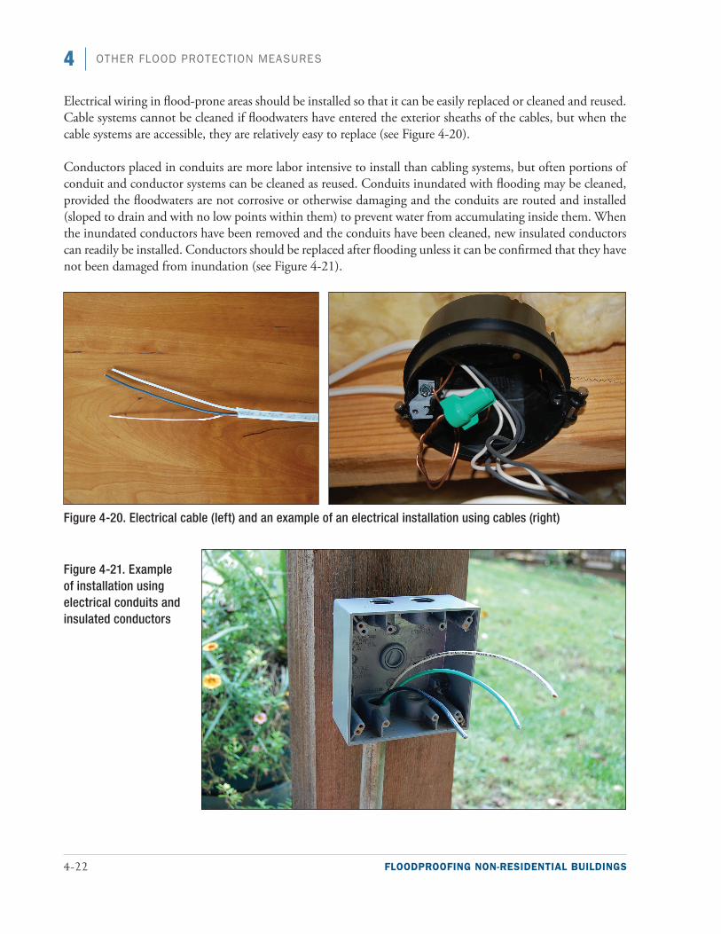
Electrical wiring in flood-prone areas should be installed so that it can be easily replaced or cleaned and reused. Cable systems cannot be cleaned if floodwaters have entered the exterior sheaths of the cables, but when the cable systems are accessible, they are relatively easy to replace (see Figure 4-20).
Conductors placed in conduits are more labor intensive to install than cabling systems, but often portions of conduit and conductor systems can be cleaned as reused. Conduits inundated with flooding may be cleaned, provided the floodwaters are not corrosive or otherwise damaging and the conduits are routed and installed (sloped to drain and with no low points within them) to prevent water from accumulating inside them. When the inundated conductors have been removed and the conduits have been cleaned, new insulated conductors can readily be installed. Conductors should be replaced after flooding unless it can be confirmed that they have not been damaged from inundation (see Figure 4-21).
Figure 4-20. Electrical cable (left) and an example of an electrical installation using cables (right)
Figure 4-21. Example of installation using electrical conduits and insulated conductors

FLOODPROOFING NON-RESIDENTIAL BUILDINGS 4-23
4OTHER FLOOD PROTECTION MEASURES
Since the severity of a flood cannot readily be predicted, wiring should be installed so the smallest possible por-tion of the system will be rendered inoperative from any given flood. For example, because of the low elevation of wiring for receptacles, this wiring should be separate from the wiring that supplies lighting fixtures. Where possible, all electrical equipment in flood-prone portions of a building should be placed as high as practical.
As with electrical service equipment, communication service equipment should be elevated above the DFE, and communication wiring should be routed and installed in such a way that damage and service interruptions resulting from inundation will be minimized. Providing connectors that can isolate damaged communication wiring from wiring routed above floodwaters will allow portions of the communication system to be placed back in service and used while flood-damaged portions of the wiring are replaced. Installing communication wiring that is vulnerable to flooding in conduits can greatly facilitate cable replacement even when conduits are not required to satisfy codes and standards.
4.3.2 Mechanical Utilities and Systems
The approach to limiting damage to mechanical utilities and systems is the same as electrical utilities and sys-tems. All equipment that is vulnerable to flooding should be elevated above the DFE and when that is not possible, located in dry-floodproofed areas. Equipment that must be placed in areas prone to flooding should be designed to (1) minimize disruptions to the portions of the mechanical systems that are above the floodwa-ters and (2) facilitate removal and replacement of flood-damaged mechanical equipment.
Large central mechanical units such as chillers, particularly air-cooled chillers, boilers, and pumps, should be placed above the DFE. For existing installations, the area where central mechanical units are located should be dry floodproofed if elevation is not practical. Evaporator towers can be placed below the DFE if they can be readily cleaned or if the evaporative media are replaced after being in contact with floodwaters. HVAC con-trols, many of which must be placed near the mechanical equipment they serve, should be placed as high as possible and installed in a way that facilitates their replacement if they are damaged by floodwaters. Central processing units that provide supervisory control can and should be installed above the DFE.
As with electrical panelboards, dedicated air handling units should be installed to serve flood-prone areas. Air handling units vulnerable to flood damage should have independent supplies, returns, and ventilation ducts that prevent cross contamination of conditioned air between areas damaged by floodwaters and those above the floodwaters. Isolation valves should be installed to allow damaged HVAC components to be replaced with-out requiring draining or disrupting chilled water or hot water distribution systems. In addition, domestic water lines supplying fixtures in flood-prone levels should be isolated from domestic water lines serving upper floors.
Exhaust vents and fresh air make-up vents should be relocated above the DFE. If relocation is not possible, flood shields may need to be installed to prevent water entry.
To prevent floodwaters from entering non-pressurized mechanical systems, check valves should be installed where allowed by code and local regulations. All check valves should be installed so they can be maintained and tested periodically.

4-24 FLOODPROOFING NON-RESIDENTIAL BUILDINGS
4 OTHER FLOOD PROTECTION MEASURES
Fuel tanks in areas vulnerable to flooding should be designed to resist the crushing pressures that exist at their flood depth and anchored to resist buoyant forces that result from inundation. ASCE 24 requires that tanks be designed and anchored to resist 1.5 times the potential flood forces acting on a tank when it is empty.
Where possible, piping that needs to be insulated should be run above the DFE. Where piping must be installed below the DFE, flood-resistant insulation must be used. Piping should be installed in a fashion that facilitates insulation replacement.
4.4 Emergency MeasuresEmergency measures are temporary measures that are implemented between the flood warning and the flood event to protect the building from floodwaters. Sandbags, temporary flood barriers, and flood wrapping sys-tems are common emergency flood protection measures and are described in the following subsections.
4.4.1 Sandbags
The use of sandbags has changed little over time. Temporary walls constructed of sandbags can be used to pro-tect structures from flooding or provide additional height to existing levee systems when floodwaters reach critical levels. Typical sandbags are constructed of plastic or treated burlap bags approximately 14 inches wide and 24 inches long and are filled with sand or other fine-grained soils.
The various USACE districts have prepared guidance on the proper use and placement of sandbags to provide temporary protection of structures from flooding (see Figure 4-22). However, unless emergency placement is planned well in advance under the direction of trained personnel, most sandbag barriers are not constructed in accordance with proper practices, leading to leakage and failures. Because of the intensive effort and amount of time required to provide protection even from relatively shallow water, sandbag walls are not a reliable protec-tion measure. To be effective, sandbags and sand should be stockpiled and checked regularly to ensure that the sandbags have not deteriorated. Sand and/or filled sandbags stored unprotected out of doors in cold weather climates may freeze and be rendered unusable.
The disadvantages of sandbags are high disposal costs and a tendency to absorb pollutants from contaminated floodwaters, which necessitates their disposal as hazardous waste.

FLOODPROOFING NON-RESIDENTIAL BUILDINGS 4-25
4OTHER FLOOD PROTECTION MEASURES
Figure 4-22. Techniques for proper placement of sandbags (source: USACE St. Paul District)
4.4.2 Temporary Flood Barriers
A number of vendors make temporary flood barriers that can be assembled relatively easily, moved into place, anchored, and filled with water (see Figure 4-23) or sand (see Figure 4-24). The barriers must be sized for the site. Training and annual drills are important so personnel know how to deploy the barriers. Proper storage, including cleaning after deployment, is necessary to protect the materials over long periods.
The Association of State Floodplain Managers (ASFPM) Non-Structural Floodproofing Committee worked with the USACE’s National Non-Structural Flood Proofing Committee and Underwriters Laboratories (UL) to establish a testing/certification program for temporary flood barriers. ASFPM, UL, and USACE initiated program development, and FM Approvals (a division of FM Global) developed an approval system for rec-ognizing temporary barriers as flood abatement equipment for their policyholders. In 2006, FM Approvals published FM Standard 2510, Approval Standard for Flood Abatement Equipment (FM Approvals 2006). The current FM Approvals test protocols are for self-supporting, temporary barriers designed to protect against riv-erine flood depths up to 3 feet; however, the laboratory set-up can be adapted easily to allow for testing panel closures and demountable barriers. These barriers are not tested for coastal flooding applications, where the presence of saltwater may hinder their performance. Because saltwater is denser than freshwater, a barrier filled with freshwater in a coastal location may float instead of providing protection against flooding.

4-26 FLOODPROOFING NON-RESIDENTIAL BUILDINGS
4 OTHER FLOOD PROTECTION MEASURES
4.4.3 Flood Wrapping Systems
Flood wrapping systems are temporary emergency measures. They consist of plastic or other synthetic water-proof sheeting material that is used to seal a building to prevent water intrusion during the flood duration. Wrapping systems present different challenges from impervious wall systems: they need to be anchored, stored, and repaired.
Flood wraps benefit from barrier reinforcement such as sandbags or plywood walls and should generally be able to withstand the pressure of 3 feet of water for a limited period. Wrapping systems rely on the existing walls, which may need to be strengthened to resist flood loads, but they also need to bridge openings such as doors and windows, which typically require some type of temporary reinforcement to support the portion of the wrapping system that spans the openings. The area of openings and the flood protection level should be considered when selecting the wrapping material. When using flood wrapping material, refer to the manu-facturer’s specifications for depth of flooding limitations, reinforcement requirements, and applicability with
Figure 4-24. Gravel-filled containers that formed a barrier to protect the University of Iowa (2008)
Figure 4-23. Three-foot-high water-filled temporary barrier protecting a structure in Tunica, MS (source: Hydrological Solutions, Inc.)

FLOODPROOFING NON-RESIDENTIAL BUILDINGS 4-27
4OTHER FLOOD PROTECTION MEASURES
existing construction materials at the openings. Figure 4-25 illustrates a span across a doorway where the wrap is deflecting due to flood loads. These situations should be avoided because the stress of the wrap deflecting could cause it to tear and leak.
Figure 4-26 shows plastic sheeting attached to a brick-faced wall. Weep holes and wick drains work both ways to allow moisture to pass from high to low pressure. Weep holes and flashing should therefore be above the DFE, and the veneer below that level should be fully grouted. Wrapping systems should be selected using the decision process shown in Figure 4-27.
Figure 4-25. Plan view of wall section showing the deflection of a wrap at a doorway
Figure 4-26. Plastic sheeting attached to a brick-faced wall to seal it from water intrusion
Wall
Deflection of wrap Wrap
DoorWall
Design floodelevation Attach to building
6 mil. polyethylene placed loosely on wall
Brick veneer
Sand bags
Loosesand
Grade
6˝ to 8˝
8˝ to 10˝
Monolithic slaband footing
Maximumheight = 3 ft
CMUwall
4˝ PVC perforated pipe(drain to sump withbackup power source)

4-28 FLOODPROOFING NON-RESIDENTIAL BUILDINGS
4 OTHER FLOOD PROTECTION MEASURES
Figure 4-27. Decision process for the selection and design of a flood wrapping system

FLOODPROOFING NON-RESIDENTIAL BUILDINGS 4-29
4OTHER FLOOD PROTECTION MEASURES
Wrap systems require secure connections at both the top and bottom of the wrap. The actual loads imposed vertically on the wrap are difficult to determine because they can vary depending on the quality of the instal-lation. Since the intent of flood wrapping systems is to provide floodproofing and not structural support, voids left from poor construction may force the wrap to carry the weight of the water and should be avoided.
The following should be considered when selecting the method to attach the wrap to the building:
■■ The wall attachment system should uniformly support the wrap. Small spacing between the connections and a member with some rigidity on the outside of the wrap can provide the needed support.
■■ The existing wall construction can vary widely. Part of the connection may need to be a permanent part of the wall.
Anchoring wrap into the grade at the base of a wall is the most important link in the wrap system (see Figure 4-24). The following recommendations should be followed during selection and design of a grade connection method:
■■ A drain line connected to a sump pump should be located between the wrap and the building to remove any water that leaks through the wrap or seeps through the soil under the at-grade anchor.
■■ The end of the wrap should be buried at least below the topsoil layer. Additional ballast may be needed (e.g., sandbags, stone) to prevent wrap movement in a saturated or frozen soil condition.
■■ The product literature for the wrap material and applicable codes and standards should be reviewed and followed.
Before the final selection of a wrapping system, the following issues should be addressed by the manufacturer and the instructions should be provided to the owner:
■■ Based on the type of building the wrapping system will be applied to, any issues with chemicals used or stored onsite that could damage the wrapping system should be identified. It is also important for the designer or owner to evaluate adjacent properties to make sure that any potential chemicals that could damage the wrapping system during a flood have been identified.
■■ The manufacturer should provide guidance on how to repair the wrapping system and approximately how much additional wrapping material is required for each repair. It is also important to know whether the wrapping material can be repaired once it has gotten wet or whether it must be dry.
4.5 Combination of Floodproofing MeasuresSome non-residential buildings and site conditions require multiple floodproofing measures for adequate pro-tection. A single floodproofing measure may provide only limited protection or protect only a portion of a single building or group of buildings. In these situations, combining floodproofing measures may be appropri-ate. Combining floodproofing measures is discussed in the following subsections.
Special Note
Wrap systems may be affected by freeze-thaw cycles. Careful evaluation of performance in frozen climates is advisable and installation in accordance with manu-facturer instructions is recommended.

4-30 FLOODPROOFING NON-RESIDENTIAL BUILDINGS
4 OTHER FLOOD PROTECTION MEASURES
4.5.1 Wet and Dry Floodproofing Techniques
Many non-residential buildings can benefit from using a combination of the wet floodproofing measures described in Section 4.2 and the dry floodproofing measures described in Chapter 3. Combining measures is particularly useful when one or more of the following building or site conditions exist:
■■ Multi-story or split-level buildings where different measures can be applied to different foundation types at different elevations
■■ Large factories, warehouses, and other industrial facilities constructed of a variety of materials that respond better to multiple floodproofing measures
■■ Groups of buildings on the same site but at different elevations
Figure 4-28 shows a commercial building that was mitigated by raising the interior first floor using flood dam-age-resistant materials and flood shields and by reinforcing walls.
Retrofitting an entire large building or multiple buildings with dry floodproofing is a complex and expensive undertaking that requires analysis and design to protect the buildings against flooding from numerous points of entry of various sizes. Consequently, limiting dry floodproofing measures to the most critical elements or operations of a facility that cannot be elevated may be more technically feasible and cost effective. Building managers and owners can then focus on elevating other critical areas and wet floodproofing other lower-level areas that are less critical. This situation may apply to flood-prone hospitals, schools, fire and police stations,
Figure 4-28. Commercial structure in Darlington, WI, mitigated using a combination of wet and dry floodproofing techniques

FLOODPROOFING NON-RESIDENTIAL BUILDINGS 4-31
4OTHER FLOOD PROTECTION MEASURES
emergency operations centers, communication and data centers, essential government buildings, and other critical facilities that serve the community or affect the safety, health, or welfare of a large population.
Elevating critical equipment and operations often involves relocating them to upper floors; in many facilities, space must be created on those upper floors to house the relocated equipment and operations. Creating that space often requires moving less critical equipment and operations to areas that are more vulnerable to flood-ing. Identifying what equipment and operations can be relocated can be straightforward, as shown in Figure 4-29, or can be complex. For the building in Figure 4-29, a non-critical break room was moved to a lower floor to create space for a critical control room needed for plant operations.
In complex situations, identifying what non-critical (or less-critical) equipment and operations can be more exposed to flooding requires long-term planning because exposing any equipment to flooding can affect the facility’s ability to respond to and recover from a flood event. For example, in a health care facility, food service, laundry operations, and the facility’s electrical service and distribution equipment are all required for the facil-ity to function. However, unlike the food service and laundry operations, which can be provided by off-site suppliers, the electrical service and distribution equipment must be protected. So for installations where laun-dry or food service equipment are located on higher floors, those operations can be relocated to lower floors to free up space for essential electrical service and distribution equipment.
To improve the building performance of such facilities, vulnerability assessments that take a holistic view of critical equipment, critical systems, and critical functions should be completed to identify vulnerabilities and identify possible flood mitigation measures. Those flood mitigation measures should be incorporated when-ever damaged facilities are repaired or reconstructed. Refer to the Midwest Flood MAT Recovery Advisory, Design Considerations for Improving Critical Facility Functionality during Flood Events, in Appendix D of FEMA P-765 (FEMA 2009b) for additional details.
Figure 4-29. A non-critical break room, originally located on an upper floor was relocated to create space for the critical control room

4-32 FLOODPROOFING NON-RESIDENTIAL BUILDINGS
4 OTHER FLOOD PROTECTION MEASURES
4.5.2 Other Combinations
In addition to a combination of wet and dry floodproofing, the following combinations may increase mitiga-tion effectiveness:
■■ Dry floodproofing and floodwalls/levees. May be applicable to buildings with multi-level foundations that are suitable for dry floodproofing and the site slopes down toward the flooding source or a building where one side is less suitable for dry floodproofing (see Chapter 3 and Section 4.1)
■■ Dry floodproofing and floodproofing utilities. May be applicable to a complex of buildings or utility facilities where some structures are suitable for dry floodproofing but others are not (see Chapter 3 and Section 4.3)
■■ Dry floodproofing and emergency measures. May be applicable to buildings or facilities that are suitable for dry floodproofing but contain many large openings that can be protected with emergency measures (see Chapter 3 and Section 4.4)
■■ Wet floodproofing and emergency measures. May be applicable for building spaces that are suitable for wet floodproofing where there is a need to protect a portion of key building systems or equipment with emergency measures (see Section 4.2 and Section 4.4)
4.5.3 Case Study: Application to Historic Buildings
Darlington, WI, provides an example of how multiple floodproofing measures can be successfully imple-mented in historic structures to allow architectural and cultural resources to withstand future flooding. In response to historic floods and devastation from the 1993 Midwest Flood (see Figure 4-30), the city of Darlington developed a 10-year progressive mitigation plan to preserve the downtown business area along Main Street while maintaining its designation as a historic district (FEMA 2008c).
To increase the level of flood protection for some commercial structures along Main Street, existing basements were aba ndoned and filled with sand and gravel or concrete, and interior first floors were elevated (see Figure 4-31).
A hardware store on Main Street was mitigated by raising the interior first floor using a poured mono-lithic concrete slab and installing flood damage-resistant materials in areas below the DFE (see Figure
Figure 4-30. Flooding of businesses in historic downtown Darlington, WI, Midwest Flood (1993) (source: Wisconsin Emergency Management)

FLOODPROOFING NON-RESIDENTIAL BUILDINGS 4-33
4OTHER FLOOD PROTECTION MEASURES
4-32). The mitigation project also included an interior ramp for Americans with Disabilities Act (ADA) compliance (see Figure 4-33) as well as floodproofing of mechanical and electrical equipment.
After the floodproofing measures were implemented in the businesses on Main Street, the historic down-town district successfully withstood severe flooding in 2007 and 2008.
Figure 4-31. Businesses along Main Street in Darlington, WI, mitigated with an elevated interior first floor
Figure 4-32. Hardware store on Main Street in Darlington, WI, (left) mitigated with a raised interior first floor and flood damage-resistant materials (right)
Figure 4-33. Hardware store on Main Street in Darlington, WI, showing ramp to elevated interior first floor for ADA compliance