Embed Size (px)
Citation preview

Roche Applied Science
LightCycler® 2.0 InstrumentOperator’s Manual
* in combination with Roche LightCycler® kits labeled for in vitro diagnostic use
Software Version 4.05
Manual A: for in vitro diagnostic use*
A Proven Standard for Real-Time PCR


Table of Contents
I. Revision History................................................................................................................................................... 7
II. Contact Addresses............................................................................................................................................. 7
III. Declaration of Conformity.............................................................................................................................. 7
IV. Warranty................................................................................................................................................................... 8
V. Trademarks ............................................................................................................................................................. 8
VI. Intended Use ......................................................................................................................................................... 8
VII. License Statements for the LightCycler® 2.0 Instrument ............................................................ 9
VIII. Software License Agreement.................................................................................................................... 10Terms....................................................................................................................................................................... 11Limited Warranty.............................................................................................................................................. 11Warranty Disclaimers .................................................................................................................................... 11Limitations of Remedies.............................................................................................................................. 12General Information....................................................................................................................................... 12
IX. Preamble............................................................................................................................................................... 13
X. Usage of the LightCycler® 2.0 Instrument Operator's Manual .............................................. 13
XI. Conventions Used in this Manual .......................................................................................................... 14Text Conventions.................................................................................................................................................. 14Symbols................................................................................................................................................................... 14
XII. Warnings and Precautions.......................................................................................................................... 16Handling Precautions ........................................................................................................................................ 16General Precautions ............................................................................................................................................ 17Electrical Safety.................................................................................................................................................... 18
1. Introduction......................................................................................................................................................... 21
2. Specifications of the LightCycler® 2.0 Instrument ....................................................................... 212.1 Technical Specifications ................................................................................................................................... 212.2 General Specifications....................................................................................................................................... 212.3 Sample Capacity .................................................................................................................................................. 222.4 Shipping.................................................................................................................................................................. 222.5 Data Station........................................................................................................................................................... 22
3. Specifications for the Detection System ............................................................................................ 233.1 Excitation ................................................................................................................................................................ 233.2 Detector .................................................................................................................................................................. 233.3 Filter.......................................................................................................................................................................... 233.4 Acquisition Time .................................................................................................................................................. 23
4. Temperature Kinetics for PCR .................................................................................................................. 244.1 General .................................................................................................................................................................... 244.2 Capillary Heating Rates..................................................................................................................................... 244.3 Capillary Cooling Rates..................................................................................................................................... 244.4 Temperature Tolerances, Short Term............................................................................................................ 24
Preface Page
A Overview Page
3Preface

4
Table of Contents
1. Unpacking and Installation ........................................................................................................................ 271.1 Components of the LightCycler® 2.0 Instrument .................................................................................... 27
2. Installation ........................................................................................................................................................... 302.1 Installation Requirements................................................................................................................................. 302.2 Space and Power Requirements.................................................................................................................... 302.3 Environmental Requirements.......................................................................................................................... 312.4 Storage Conditions.............................................................................................................................................. 312.5 Installation of the LightCycler® 2.0 Instrument........................................................................................ 31
3. Starting up the Data Station ...................................................................................................................... 333.1 Installation of the Computer............................................................................................................................ 333.2 Using the CD-RW Drive.................................................................................................................................... 33
4. System Description......................................................................................................................................... 344.1 Description of the LightCycler® 2.0 Instrument....................................................................................... 344.2 Thermal Chamber ................................................................................................................................................ 354.3 Photometer............................................................................................................................................................. 36
4.3.1 Optics ....................................................................................................................................................................... 364.3.2 Detection Channels ............................................................................................................................................ 37
5. Mobile Components and Consumables.............................................................................................. 385.1 LightCycler® 2.0 Sample Carousel................................................................................................................ 385.2 LightCycler® Capillaries.................................................................................................................................... 395.3 LightCycler® 2.0 Capillary Releaser.............................................................................................................. 405.4 LightCycler® Capping Tool............................................................................................................................... 405.5 LightCycler® Sample Carousel O-Ring....................................................................................................... 415.6 How to Use the LightCycler® Capillary Releaser .................................................................................... 425.7 LC Carousel Centrifuge 2.0 .............................................................................................................................. 44
1. Introduction ......................................................................................................................................................... 47
2. Start-Up ................................................................................................................................................................. 472.1 Status LED ............................................................................................................................................................. 482.2 Lid Lock................................................................................................................................................................... 49
3. Preparing a LightCycler® Run................................................................................................................... 50
4. Abort a Run ......................................................................................................................................................... 54
5. Shut-Down........................................................................................................................................................... 54
B System Description Page
C Operation Page
LightCycler® 2.0 Instrument - Operator’s Manual Version 2.0 Manual A: for in vitro diagnostic use

Table of Contents
1. Overview of LightCycler® Software 4.05 ............................................................................................. 571.1 Starting the LightCycler® Software 4.05 ..................................................................................................... 571.2 Understanding the LightCycler® Software 4.05 Window..................................................................... 60
1.2.1 The Navigator........................................................................................................................................................ 611.2.2 The Menu Bar and Global Toolbar ................................................................................................................ 621.2.3 The Work Pane ..................................................................................................................................................... 641.2.4 The Module Bar ................................................................................................................................................... 65
1.3 Opening, Creating, and Saving Objects...................................................................................................... 661.4 Copying Items....................................................................................................................................................... 661.5 Renaming and Deleting Objects ................................................................................................................... 66
2. Using Reports, Charts, Queries and Instrument Tools................................................................. 672.1 Viewing and Printing a Report ........................................................................................................................ 672.2 Working with Charts........................................................................................................................................... 69
2.2.1 Printing, Exporting, and Copying Charts .................................................................................................... 692.2.2 Zooming and Panning to View Chart Details ........................................................................................... 72
2.3 Using Queries to Find Information................................................................................................................ 732.3.1 Updating the Database...................................................................................................................................... 74
2.4 Using Diagnostic Tools...................................................................................................................................... 752.4.1 Performing an Instrument Self Test .............................................................................................................. 752.4.2 Viewing the Instrument Logs .......................................................................................................................... 752.4.3 Viewing Application Errors ............................................................................................................................... 76
3. Using Roche Macros ...................................................................................................................................... 773.1 Installing and executing a Roche Macro..................................................................................................... 77
3.1.1 Installing a Roche Macro .................................................................................................................................. 773.1.2 Executing a Roche Macro ................................................................................................................................. 783.1.3 Import a SAM file ................................................................................................................................................ 813.1.4 Modifying a Roche Macro ............................................................................................................................... 82
3.2 Adding and Deleting Macro Buttons on the Front Window ................................................................ 87
4. Managing User Access ................................................................................................................................ 884.1 Understanding User Accounts....................................................................................................................... 884.2 Understanding Groups...................................................................................................................................... 894.3 Understanding Roles ......................................................................................................................................... 89
4.3.1 Privileges of the Standard User Role ........................................................................................................... 904.3.2 Privileges of the Expert User Role................................................................................................................. 914.3.3 Privileges of the Local Administrator Role................................................................................................. 924.3.4 Privileges of the Roche User and Roche Role.......................................................................................... 92
4.4 Managing Users, Groups, and Roles ........................................................................................................... 934.4.1 Working with Users ............................................................................................................................................ 944.4.2 Working with Groups ......................................................................................................................................... 964.4.3 Working with Roles.............................................................................................................................................. 97
4.5 Changing your Password ................................................................................................................................. 98
5. Installation of LightCycler® Software 4.05........................................................................................ 995.1 Overview of Software Installation.................................................................................................................. 995.2 Hardware and Software Requirements....................................................................................................... 995.3 Installing LightCycler® Software 4.05........................................................................................................ 100
5.3.1 Saving an existing database and installing additional databases.................................................. 1055.3.2 Logging on to different databases.............................................................................................................. 111
5.4 Removing LightCycler® Software 4.05...................................................................................................... 1135.5 Changing the Default Administrator Password and Creating User Accounts ........................... 1155.6 Connecting an Instrument ............................................................................................................................. 118
5.6.1 Adding a New Instrument Automatically ................................................................................................. 1185.6.2 Adding a New Instrument Manually .......................................................................................................... 1205.6.3 Removing an Instrument ................................................................................................................................ 121
D Software Page
5Preface

6
Table of Contents
1. General Maintenance .................................................................................................................................. 125
2. Cleaning Instructions .................................................................................................................................. 1252.1 General Cleaning ............................................................................................................................................... 1252.2 Preventive Maintenance.................................................................................................................................. 1252.3 Removable Fan ................................................................................................................................................... 126
3. Change of O-Ring .......................................................................................................................................... 1283.1 Removal of the O-Ring.................................................................................................................................... 1283.2 Insertion of the O-Ring.................................................................................................................................... 129
4. Consumables and Spare Parts ............................................................................................................... 1304.1 Consumables....................................................................................................................................................... 1304.2 Spare Parts........................................................................................................................................................... 130
5. Disposal of Consumables and Reagents.......................................................................................... 130
1. Instrument Errors ........................................................................................................................................... 133
2. Instrument-Related Errors ........................................................................................................................ 138
3. Algorithm Errors and Messages ............................................................................................................ 142
4. Miscellaneous messages .......................................................................................................................... 144
5. Index...................................................................................................................................................................... 145
E Maintenance Page
F Troubleshooting Page
LightCycler® 2.0 Instrument - Operator’s Manual Version 2.0 Manual A: for in vitro diagnostic use

Preface
Preface
I. Revision History
Copyright 2005, Roche Diagnostics GmbH. All rights reserved.
II. Contact Addresses
III. Declaration of Conformity
The LightCycler® 2.0 Instrument meets the requirements of the European Directive forIn vitro diagnostic medical devices 98/79/EC.
Compliance is demonstrated by the following mark:
Version Revision Date
1.1 October 2003
2.0 April 2005
Roche Instrument Center AGForrenstrasseCH-6343 RotkreuzSwitzerland
Distribution Roche Diagnostics GmbHSandhofer Straße 116D-68305 MannheimGermany
Distribution in USA Roche Diagnostics 9115 Hague RoadPO Box 50457Indianapolis, IN 46250USA
7Preface

8
Preface
IV. Warranty
Information on warranty conditions are specified in the sales contract. Contact yourRoche representative for further information.
Any unauthorized modification of the instrument entails the invalidity of the guaranteeand service contract.
V. Trademarks
LightCycler® and MagNA Pure are registered trademarks of a Member of the RocheGroup.
Microsoft and Microsoft Windows are either registered trademarks or trademarks ofMicrosoft Corporation in the United States and/or other countries.
Pentium is a trademark of Intel.
VI. Intended Use
The LightCycler® 2.0 Instrument is intended for performing rapid PCR (PolymeraseChain Reaction) with real-time detection and/or quantification of a target NA (nucleicacid), as well as post-PCR analysis of the amplified NA by melting curve analysis.The LightCycler® 2.0 Instrument is designed for in vitro diagnostic applications incombination with the LightCycler® reagent kits manufactured by Roche and labeled fordiagnostic purposes (according to the workflow described in the package insert of therespective LightCycler® reagent kit). The LightCycler® 2.0 Instrument can also be used inlife science research, food analysis, forensics and other laboratory disciplines, where PCRapplications and melting curve analysis is required.
Please note: The Roche LightCycler® reagent kits for in vitro diagnostic applicationsrequiring this instrument are not available in all countries. Any diagnostic use of theLightCycler® 2.0 Instrument in combination with the LightCycler® reagents (other thanthose labeled for diagnostic purposes, manufactured by Roche and recommending theLightCycler® 2.0 Instrument in their instructions of use) is in the sole responsibility ofthe user and has to be validated by the user, taking into account all relevant nationallegislation.Customers using Roche in vitro diagnostic LightCycler® kits have to use “Manual A,marked for in vitro diagnostic use” (not available in all countries; id. no. 04 624 491 001)while “Manual B, marked for general laboratory use” (id. no. 04 624 505 001) has to beused for all other laboratory applications.
The LightCycler® 2.0 Instrument must be used exclusively by laboratory professionalstrained in laboratory techniques and having studied the instructions for use of thisinstrument.
LightCycler® 2.0 Instrument - Operator’s Manual Version 2.0 Manual A: for in vitro diagnostic use

Preface
VII. License Statements for the LightCycler® 2.0 Instrument
The LightCycler® 2.0 Instrument is designed for in vitro diagnostic ("IVD") applications.LightCycler® reagent kits manufactured by Roche and labeled for In Vitro Diagnostic Usewill provide the user with a license to perform PCR-based IVD testing. For IVD testingperformed without an IVD kit from Roche, a separate diagnostic service license is avail-able. For information on acquiring a diagnostic service license, please contact either thePCR Licensing Manager, Roche Molecular Systems, Inc., 1145 Atlantic Avenue, Alameda,California 94501 USA; Tel: 510-814-2984; Fax: 510-814-2977, or PCR Licensing Manager,Roche Diagnostics GmbH, Sandhofer Strasse 116, D-68305 Mannheim, Germany; Tel:+49 (621) 759 28 36; Fax: +49 (621) 759 27 05.
The LightCycler® 2.0 Instrument can also be used in life science research, food analysis,forensics and other laboratory disciplines, where PCR applications and melting curveanalysis is required. A license to perform PCR for life science research is obtained asdescribed below. For information on licenses to perform PCR for food analysis, foren-sics, etc., please contact either the PCR Licensing Managers listed above, or the Directorof Licensing at Applied Biosystems, as listed below.
The LightCycler® 2.0 Instrument is an Authorized Thermal Cycler. Its purchase priceincludes the up-front fee component of a license under patents on the Polymerase ChainReaction ("PCR") process, owned by Roche Molecular Systems Inc. and F. Hoffmann-LaRoche Ltd, to practice the PCR process for internal research and development using thisinstrument. The running royalty component of that license may be purchased fromApplied Biosystems or obtained by purchasing Authorized Reagents. Its use with Autho-rized Reagents provides a limited PCR license in accordance with the label rights accom-panying such reagents. This instrument is also an Authorized Thermal Cycler for usewith applications licenses available from Applied Biosystems. Purchase of this productdoes not itself convey to the purchaser a complete license or right to perform the PCRprocess. Further information on purchasing licenses to practice the PCR process forresearch and certain other fields may be obtained by contacting the Director of Licensingat Applied Biosystems, 850 Lincoln Centre Drive, Foster City, California 94404. AppliedBiosystems does not guarantee the performance of this instrument.
9Preface

10
Preface
VIII. Software License Agreement
Read this Software License Agreement ("Agreement") before removing the program CD(hereinafter referred to as program media) or product documentation from its protectivecover. Removing the program media or product documentation from the protectivecover will constitute acceptance of the terms and conditions of this Agreement. Byaccepting the terms and conditions of this Agreement, the end-user ("Licensee") assumesall responsibility and liability for the selection of this software program, hereinafterreferred to as "Software", to achieve the intended results, and for its installation and sub-sequent use. If Licensee is not willing to be bound by the terms and conditions of thisAgreement, the unopened package must be promptly returned to Roche DiagnosticsGmBH (“RDG”) with a copy of the receipt. The license fee will be refunded upon receiptby RDG of the unopened package.
Program License Agreement
You assume all responsibility and liability for the selection of this software program, here-inafter referred to as Product, to achieve your intended results, and for its installation andsubsequent use.
Grant of Software License
RDG grants to Licensee a non-exclusive, single-use license to use the Software upon theterms and conditions contained in this Agreement. Licensee may:
1. Use the Software on a single workstation owned, leased or otherwise controlled byLicensee.
2. Make one (1) copy of the Software solely for backup purposes in support of Licensee’suse of the Software on a single workstation.
3. Transfer the Software product and assign the rights under this Agreement to anotherparty, provided that the other party agrees in writing to accept the terms and condi-tions of this Agreement. If the Software is transferred, and the rights under this Agree-ment are so assigned, Licensee must, at the same time, either transfer Licensee’s copy,if any, of the Software to the same party, or destroy any such copy not transferred. Inaddition, Licensee must ensure that the copyright notice is maintained on the Softwaretransferred and on any copy concurrently transferred.
Licensee may not:1. Use or copy the Software, in whole or in part, except as expressly provided in this
Agreement.
2. Use the Software on more than one workstation at a time.
3. Copy, sell, or otherwise transfer the Software or assign its rights under this Agreement,in whole or in part, to another party, except as specifically set forth in this Agreement.
4. Rent, distribute, license or sublicense the Software.
5. Create derivative works based on Software.
6. Modify, adapt, translate, reverse engineer, decompile or disassemble the Software.
RDG reserves all rights not expressly granted herein, including, but not limited to, therights to market the Software either directly or through affiliates, distributors and/orthird parties.
For further information, please contact:
Roche Diagnostics GmbHRoche Applied ScienceSandhoferstraße 116D-68305 MannheimGermany
LightCycler® 2.0 Instrument - Operator’s Manual Version 2.0 Manual A: for in vitro diagnostic use

Preface
Terms
The Agreement is effective until terminated. Licensee may terminate this Agreement atany time by destroying the Software together with any copy previously made in compli-ance with the terms of this Agreement and documentation relating to the Software in anyform. The Agreement will terminate automatically and without notice from RDG, if Lic-ensee fails to comply with any term or condition of this Agreement. Licensee agrees todestroy the Software and the copy, if any, of the Software upon termination of this Agree-ment by RDG.
Limited Warranty
The Product is provided as is without warranty of any kind, either expressed or implied,including, but not limited to the implied warranties of merchantability and fitness for aparticular purpose. The entire risk as to the quality and performance of the Product iswith you as Licensee, should the Product prove to be defective. You assume the entirecosts of all necessary servicing, repair, or correction. However, Roche Diagnostics GmbHwarrants that the program media on which the software is furnished is free from defectsin materials and workmanship under normal use for a period of ninety (90) days fromthe date of delivery as evidenced by a copy of your receipt. ROCHE DIAGNOSTICSGMBH MAKES NO FURTHER WARRANTIES OR GUARANTEES NOR EXPLICITNOR IMPLIED.
Warranty Disclaimers
THE WARRANTY SET FORTH IN THE PREVIOUS PARAGRAPH, IS IN LIEU OF ALLOTHER WARRANTIES, EXPRESS OR IMPLIED, ARISING BY LAW, FROM A COURSEOF PERFORMANCE, A COURSE OF DEALING, TRADE USAGE, OR OTHERWISE.RDG AND ANY ENTITY CONTROLLING, CONTROLLED BY OR UNDER COM-MON CONTROL WITH RDG ("RDG AFFILIATE") SPECIFICALLY DISCLAIM,WITHOUT LIMITATION, ALL WARRANTIES OF ANY KIND, WHETHER EXPRESSOR IMPLIED, INCLUDING, WITHOUT LIMITATION, THE IMPLIED WARRANTIESOF MERCHANTABILITY, FITNESS FOR A PARTICULAR PURPOSE, AND NON-INFRINGEMENT. RDG AND RDG AFFILIATES MAKE NO REPRESENTATION ORWARRANTY AS TO THE SOFTWARE OR AS TO THE RESULTS TO BE ATTAINED BYLICENSEE COMPANY OR ANY THIRD PARTY FROM THE SOFTWARE. LICENSEEACKNOWLEDGES THAT IT HAS NOT RELIED UPON ANY REPRESENTATIONS ORWARRANTIES MADE BY RDG OR AN RDG AFFILIATE EXCEPT FOR THOSEEXPRESSLY AND SPECIFICALLY SET FORTH IN THIS AGREEMENT.
11Preface

12
Preface
Limitations of Remedies
RDG’s sole liability and your sole remedy shall be:
1. the replacement of the program media not meeting RDG’s limited warranty andwhich is returned to RDG with a copy of your receipt;
2. if RDG is unable to deliver replacement program media which is free of defects inworkmanship, you may terminate this Agreement by returning the Product and a copyof your receipt to RDG, and your money will be refunded.
IN NO EVENT WILL RDG OR ANY RDG AFFILIATE (OR THEIR RESPECTIVEOFFICERS, EMPLOYEES, CONSULTANTS, ATTORNEYS OR AGENTS), BE LIABLEFOR ANY SPECIAL, INDIRECT, INCIDENTAL, OR CONSEQUENTIAL DAMAGES(INCLUDING, BUT NOT LIMITED TO, LOST PROFITS, LOST DATA OR INFORMA-TION, LOSS OF USE OF THE SOFTWARE, BUSINESS INTERRUPTION, LOSS OFBUSINESS REPUTATION OR GOODWILL, OR DOWNTIME COSTS) WHICH THELICENSEE OR OTHERS MAY INCUR OR EXPERIENCE, DIRECTLY OR INDIRECTLYARISING OUT OF OR RELATING TO THE SOFTWARE, THIS AGREEMENT, OR THETERMINATION OF THIS AGREEMENT, EVEN IF RDG OR AN RDG AFFILIATE HASBEEN ADVISED OF THE POSSIBILITY OF SUCH DAMAGES AND NOTWITH-STANDING ANY FAILURE OF ESSENTIAL PURPOSE. THE AGGREGATE LIABILITY,ON A COMBINED BASIS, OF RDG AND RDG AFFILIATES (AND THEIR RESPEC-TIVE OFFICERS, EMPLOYEES CONSULTANTS, ATTORNEYS, AND AGENTS) FORDAMAGES FOR ANY CAUSE WHATSOEVER DIRECTLY OR INDIRECTLY RELAT-ING TO OR ARISING OUT OF THIS AGREEMENT OR THE SOFTWARE, ANDREGARDLESS OF THE FORM OF ACTION, SHALL BE LIMITED TO, AT RDG’sOPTION, REPLACEMENT OF THE SOFTWARE OR REFUND OF THE FEESRECEIVED BY RDG OR AN RDG AFFILIATE FROM LICENSEE WITH RESPECT TOTHE SOFTWARE.
General Information
You may not sublicense, assign or transfer the license or the Product, in whole or in part,except as expressly provided in this Agreement. Any attempt otherwise to sublicense,assign or transfer any of the rights, duties or obligations hereunder is void.
� This Agreement will be governed by the laws of Germany.
� Should any part of this agreement be declared void or unenforceable by a court ofcompetent jurisdiction, the remaining terms shall remain in full force and effect.
� Failure of RDG to enforce any of its rights in this Agreement shall not be considered awaiver of its rights, including but not limited to its rights to respond to subsequentbreaches.
By opening and using this software you acknowledge that you have read this Agreement,understand it, and agree to be bound by its terms and conditions. You further agree thatthis Agreement is the complete and exclusive statement of the Agreement between youand RDG and supersedes any proposal or prior Agreement, oral or written, any othercommunications between you and RDG relating to the subject matter of this Agreement.
LightCycler® 2.0 Instrument - Operator’s Manual Version 2.0 Manual A: for in vitro diagnostic use

Preface
IX. Preamble
Before setting-up operation of the LightCycler® 2.0 Instrument it is important to readthis Operator's Manual thoroughly and completely. Non-observance of the instructionscontained in this manual may entail safety hazards.
X. Usage of the LightCycler® 2.0 Instrument Operator's Manual
This Operator's Manual assists with operating the LightCycler® 2.0 Instrument. Itcontains the following chapters:
Chapter A Overview contains a short introduction in the operating mode of theLightCycler® 2.0 Instrument and describes the system's specifications.
Chapter B System Description contains instructions on the installation of theLightCycler® 2.0 Instrument and a description of the system's components andconsumables.
Chapter C Operation describes the operating procedures for the LightCycler® 2.0Instrument.
Chapter D Software contains instructions for using Roche Macros.
Chapter E Maintenance describes the maintenance procedures that are required for theLightCycler® 2.0 Instrument.
Chapter F Troubleshooting lists all LightCycler® system messages, explains their mean-ing and indicates appropriate measures.
13Preface

14
Preface
XI. Conventions Used in this Manual
Text Conventions
To impart information consistent and memorable, the following text conventions are
used in this Operator's Manual:
Symbols
In this Operator's Manual symbols are used as an optical signal to point out important
things.
Text Convention Usage
Numbered Listing Steps in a procedure that must be performed in the order listed.
Italic Type - Points to a different chapter in this Operator's Manual which should be consulted.
- Describes how to proceed when operating the LightCycler® Software
Symbol Heading Description
WARNING This symbol is used to indicate that non-compliance with instructions or procedures may lead to physical injury or even death or could cause damage to the instrument. Consult the Operator's Manual.
HOT SURFACE This symbol is used to label potentially hot instrument surfaces.
BIOHAZARD This symbol is used to indicate that certain precautions must be taken when working with potentially infectious material.
IMPORTANT NOTE Information critical to the success of the procedure or use of the product.
INFORMATION NOTE Additional information about the current topic or procedure.
LightCycler® 2.0 Instrument - Operator’s Manual Version 2.0 Manual A: for in vitro diagnostic use
Preface
The following symbols appear on the instrument
Manufacturer of device.On the instrument type plate.
WarningOn the instrument type plate (see XII Handling Precautions).
Hot surfaceOn the margin of the thermal chamber (see XII Handling Precautions).
The CE mark on the instrument type plate expresses conformity with essential requirements of the directive relevant for this instrument (see III).
cUL markOn the instrument type plate (see Chapter Overview, 2.2 General specifications)
15Preface

16
Preface
XII. Warnings and Precautions
The LightCycler® 2.0 Instrument must only be used by trained and skillful personnel.
It is essential that the following safety informations required for installation andoperation of the LightCycler® 2.0 Instrument are carefully read and observed. Pleaseassure that these safety informations are accessible for every employee working with theLightCycler® 2.0 Instrument.
Handling Precautions
The LightCycler® 2.0 Instrument is an electromechanical instrument. There is a potential danger for the user of an electric shock or physical injury if the instrument is not used according to the instructions given in this manual.�Follow all safety instructions printed on, or attached to the analytical
instrument.�Observe all general safety precautions which apply to electrical instruments.�Never touch switches or power cord with wet hands.�Do not open the housing of the LightCycler® 2.0 Instrument.�Never clean the instrument without turning the instrument power switch off
and disconnecting the power cord. Only authorized service personnel should perform service or repairs
required for this unit.
�Do not open the thermal chamber during operation.�When programming a run, always include a cooling step (e.g. 40°C for
30 sec) as last cycle program to make sure that the thermal chamber has cooled down upon opening the lid.
�Although working with highly purified nucleic acids, please regard for your own safety all biological material as potentially infectious. Handling and disposal of such material should be performed according to local safety guidelines.
�Always wear safety goggles and gloves when dealing with toxic, caustic or infectious materials.
�Please refer to chapter Maintenance to find instructions for cleaning the LightCycler® 2.0 Instrument.
�The chamber lid and the sample carousel are hot while the instrument is operating.
The corresponding symbol is attached to the upper margin of the thermal chamber.
LightCycler® 2.0 Instrument - Operator’s Manual Version 2.0 Manual A: for in vitro diagnostic use

Preface
General Precautions
The LightCycler® 2.0 Instrument must not be connected to a network, although network hardware is present. The connection to networks contains an inherent risk to be infected through viruses and worms as well as targeted attacks through malicious attackers through the network. Roche is not responsible for any damages caused by connection of the LightCycler® 2.0 Instrument to a network by the customer.
Additional software must not be installed on the LightCycler® 2.0 workstation. Installation of additional software contains the risk to interfere with LightCycler® Software 4.05 and may affect result security.
One PC must not be used with 2 LightCycler® Instruments simultaneously.
Do not manipulate the instrument.
17Preface

18
Preface
Electrical Safety
The LightCycler® 2.0 Instrument is designed in accordance with Protection Class I (IEC). The chassis/housing of the instrument is connected to Protection Earth (PE) by means of a cord. For protection against electrical shock hazards, the instrument must be directly connected to an approved power source such as a 3-wire grounded receptacle for the 115V or 230V line. Where an ungrounded receptacle is encountered, a qualified electrician must replace it with a properly (PE) grounded receptacle in accordance with the local electrical code. An extension must not be used. Any break in the elec-trical ground path, whether inside or outside the instrument, may create a hazardous condition. Under no circumstances should the user attempt to modify or deliberately defeat the safety features of this instrument. If the power cord becomes cracked, frayed, broken, or otherwise damaged, it must be replaced immediately with the equivalent part from Roche Diagnostics.
LightCycler® 2.0 Instrument - Operator’s Manual Version 2.0 Manual A: for in vitro diagnostic use
Chapter A • Overviewcontains a short introduction in the operating mode of the LightCycler® 2.0 Instrument and describes the system‘s specifications.
Overview

20
AA
LightCycler® 2.0 Instrument - Operator’s Manual Version 2.0 Manual A: for in vitro diagnostic use
1. Introduction ...........................................................................................................................................................21
2. Specifications of the LightCycler® 2.0 Instrument .........................................................................212.1 Technical Specifications......................................................................................................................................212.2 General Specifications.........................................................................................................................................212.3 Sample Capacity ....................................................................................................................................................222.4 Shipping ....................................................................................................................................................................222.5 Data Station.............................................................................................................................................................22
3. Specifications for the Detection System ..............................................................................................233.1 Excitation ..................................................................................................................................................................233.2 Detector.....................................................................................................................................................................233.3 Filter ............................................................................................................................................................................233.4 Acquisition Time ....................................................................................................................................................23
4. Temperature Kinetics for PCR.....................................................................................................................244.1 General ......................................................................................................................................................................244.2 Capillary Heating Rates.......................................................................................................................................244.3 Capillary Cooling Rates .......................................................................................................................................244.4 Temperature Tolerances, Short Term..............................................................................................................24
A Overview Page
Overview

AAIntroduction
Overview
1. Introduction
The LightCycler® 2.0 Instrument enables you to perform rapid PCR. Results can bequantified and analyzed simultaneously by monitoring fluorescence during amplifica-tion. Melting curve analysis allows mutation detection and product characterization.
2. Specifications of the LightCycler® 2.0 Instrument
A summary of the LightCycler® 2.0 Instrument specifications is given below.
2.1 Technical Specifications
2.2 General Specifications
Dimensions 28 x 38.5 x 50.5 cm +/- 0.5 cm tolerance (W x H x D)
Weight Approx. 22 kg
Power supply 115/230 V; 8A; 50-60 Hz
Power consumption Max. 800 VA
Noise level < 65 dBA
Heat emission 2900 kJ/h (max.)2100 kJ/h (average value during operation)
Protection Class I
Temperatures allowed during transportation/storage/packaging
-25°C to +60°C; relative humidity: 10% to 95% (no condensation)
Temperatures allowed during operation
+18°C to +30°C
Relative Humidity 10% to 95%, no condensation
Altitude/Pressure 0 to 2000 m above sea level850 – 1050 hP
Safety Complies with safety standards IEC 61010-1 and IEC 61010-2-101, level of pollution 2, Overvoltage category II, CAN/CSA-C22.2 No. 1010.1-92 as well as UL 61010A-1.
The safety mark has been issued by Underwriters Laboratories, Inc. (UL) for Canada and the US.
21Overview

22
AASpecifications of the LightCycler® 2.0 Instrument
Sample Capacity
2.3 Sample Capacity
2.4 Shipping
The LightCycler® 2.0 Instrument is transported in a styrofoam container packed in acardboard box. The container should be carefully inspected for damage. Report any dam-age to your local Roche Diagnostics office before accepting the unit.
For transportation or relocation of the LightCycler® 2.0 Instrument, only theoriginal packaging shall be used.
2.5 Data Station
A fully equipped data workstation is delivered by Roche with the LightCycler® 2.0Instrument.
The data station complies with the requirements of the following European Directives:
� Low Voltage Equipment 73/23/EEC� Electromagnetic Compatibility 89/336/EEC
In addition (for customers in the USA) the data station is certified by UnderwritersLaboratories Inc., USA with respect to electrical and mechanical safety. Consequently thedata station is marked with a UL and a CE mark.
By using special software it is possible to access the LightCycler® PC by remotecontrol. Contact your Roche representative for more information.
Number of samples per run 32
Sample volume 20 µl, 100 µl
LightCycler® 2.0 Instrument - Operator’s Manual Version 2.0 Manual A: for in vitro diagnostic use

AASpecifications for the Detection System
Excitation
3. Specifications for the Detection System
3.1 Excitation
3.2 Detector
3.3 Filter
3.4 Acquisition Time
Type High Brightness LED
Wavelength (Peak) 470 nm +/- 10 nm
Wattage at capillary position in the range of 450 nm-500nm
> 0.6 mW
Filter Interference Filter: Bandpass 470 nm, HBW 40 nm
Type Photohybrid
Resolution 16 bit
Detector Channel 1 Interference filter:Bandpass 530 nm, HBW 20 nm
Detector Channel 2 Interference filter:Bandpass 555 nm, HBW 20 nm
Detector Channel 3 Interference filter:Bandpass 610 nm, HBW 20 nm
Detector Channel 4 Interference filter:Bandpass 640 nm, HBW 20 nm
Detector Channel 5 Interference filter:Bandpass 670 nm, HBW 20 nm
Detector Channel 6 Interference filter:Bandpass 710 nm, HBW 40 nm
Acquisition Time for single capillary < 46 ms
Acquisition Time for 32 capillaries < 6 sec
23Overview

24
AATemperature Kinetics for PCR
General
4. Temperature Kinetics for PCR
4.1 General
4.2 Capillary Heating Rates
4.3 Capillary Cooling Rates
4.4 Temperature Tolerances, Short Term
Temperature range 40°C to 98°C
Accuracy of „Mean Capillary Temperature at Thermal Equilibrium“ a
a. Excluding error of measurement equipment
+/-0.4°C
Accuracy of „Displayed Temperature“ with respect to capillary temperature at thermalequilibrium a
+/-0.3°C (at 50°C and at 95°C)
Heating rate 40°C to 95°C (non-linear) 20µl: < 15 sec100µl: < 27.5 sec
Heating rate 50°C to 72°C (non-linear) 20µl: < 8 sec100µl: < 11 sec
Heating rate 72°C to 95°C (non-linear) 20µl: < 8 sec100µl: < 11.5 sec
Cooling rate 95°C to 50°C (non-linear) 20µl: < 15 sec100µl: < 24 sec
Precision of capillary temperature over all capillary positions when measured for 30 sec at 95°C
+/-0.3°C (+/-1.0°C)
Precision of capillary temperature over all capillary positions when measured for 30 sec at 70°C
+/-0.15°C (+/-0.5°C)
Precision of capillary temperature over all capillary positions when measured for 30 sec at 50°C
+/-0.3°C (+/-0.8°C)
LightCycler® 2.0 Instrument - Operator’s Manual Version 2.0 Manual A: for in vitro diagnostic use

Chapter B • System Descriptioncontains instructions on the installation of the LightCycler® 2.0 Instrument and a description of the system‘s components and consumables.
System Description

26
BB
LightCycler® 2.0 Instrument - Operator’s Manual Version 2.0 Manual A: for in vitro diagnostic use
1. Unpacking and Installation ..........................................................................................................................271.1 Components of the LightCycler® 2.0 Instrument ......................................................................................27
2. Installation ............................................................................................................................................................ 302.1 Installation Requirements.................................................................................................................................. 302.2 Space and Power Requirements..................................................................................................................... 302.3 Environmental Requirements........................................................................................................................... 312.4 Storage Conditions............................................................................................................................................... 312.5 Installation of the LightCycler® 2.0 Instrument......................................................................................... 31
3. Start up the Data Station ...............................................................................................................................333.1 Installation of the Computer..............................................................................................................................333.2 Using the CD-RW Drive......................................................................................................................................33
4. System Description.......................................................................................................................................... 344.1 Description of the LightCycler® 2.0 Instrument........................................................................................ 344.2 Thermal Chamber ..................................................................................................................................................354.3 Photometer.............................................................................................................................................................. 36
4.3.1 Optics ........................................................................................................................................................................ 364.3.2 Detection Channels ..............................................................................................................................................37
5. Mobile Components and Consumables............................................................................................... 385.1 LightCycler® 2.0 Sample Carousel................................................................................................................. 385.2 LightCycler® Capillaries..................................................................................................................................... 395.3 LightCycler® 2.0 Capillary Releaser............................................................................................................... 405.4 LightCycler® Capping Tool................................................................................................................................ 405.5 LightCycler® Sample Carousel O-Ring........................................................................................................ 415.6 How to Use the LightCycler® Capillary Releaser ......................................................................................425.7 LC Carousel Centrifuge 2.0 ............................................................................................................................... 38
B System Description Page
System Description

BB
Unpacking and Installation
Components of the LightCycler® 2.0 Instrument
System Description
1. Unpacking and Installation
The table below lists all components delivered with the LightCycler® 2.0 Instrument. Usethis list to check the completeness of all components. Check for damages in transit afteropening. Report any visual damage to your local Roche Diagnostics representative.
Do not lift the instrument by the lid handle when unpacking, instead place yourhands under the base of the instrument.
1.1 Components of the LightCycler® 2.0 Instrument
Components Description
System component 1 �LightCycler® 2.0 Instrument (Cat.No.: 03 531 414 201)
�LightCycler® 2.0 Sample Carousel (20 µl) (Cat.No.: 03 603 962 001) mounted in LightCycler® 2.0 Instrument
27System Description

28
BB
Unpacking and Installation
Components of the LightCycler® 2.0 Instrument
Components Description
System component 2 �1 box LightCycler® Capillaries (20 µl) (1 box out of Cat.No.: 11 909 339 001)
�LightCycler® 2.0 Sample Carousel (100 µl) (Cat.No.: 03 603 954 001)
�1 box LightCycler® Capillaries (100 µl)(1 box out of Cat.No.: 03 337 090 001)
�LightCycler® Centrifuge Adapters (Cat.No.: 11 909 312 001)
�2x LightCycler® Capping Tool(Cat.No.: 03 357 317 001)
�LightCycler® 2.0 Capillary Releaser(Cat.No.: 03 603 920 001)
LightCycler® 2.0 Instrument - Operator’s Manual Version 2.0 Manual A: for in vitro diagnostic use

BB
Unpacking and Installation
Components of the LightCycler® 2.0 Instrument
A fully equipped data workstation is delivered with the LightCycler® 2.0Instrument.
A printer and a barcode reader are provided locally upon request.
System component 2 �LightCycler® 2.0 Operator's Manual
�LightCycler® Software 4.05 (Cat.No.: 03 604 012 001)
�LightCycler® Software 4.05 Tutorial
�Serial cable to connect the LightCycler® 2.0 Instrument to the Computer
�Power cord (one with German plug and one with US plug)
Components Description
29System Description

30
BB
Installation
Installation Requirements
2. Installation
2.1 Installation Requirements
� Do not place the LightCycler® 2.0 Instrument next to instruments that causevibration, electromagnetic interference, or have high inductance (e.g., centrifuges ormixers).
� Peripheral instruments connected to the LightCycler® 2.0 Instrument must meet theIEC 950 (UL 1950) standard.
� All plugs used with the LightCycler® 2.0 Instrument (PC, printer, monitor) shouldhave the same phasing in order to prevent switch-on peaks and electronic noisegenerated by other instruments, or by the power supply itself.
� Use only the power lines and RS232 connector supplied.
� Do not place the instrument in direct sunlight or close to radiators or heating devices.
� Do not use the instrument in an atmosphere where an explosion could occur.
2.2 Space and Power Requirements
Place the LightCycler® 2.0 Instrument on a site that can support the following instrument
requirements:
Dimensions The LightCycler® 2.0 Instrument is 28 cm wide, 50.5 cm long and 38.5 cm high.
Weight The LightCycler® 2.0 Instrument has a weight of approximately 22 kg.
Voltage requirements
The LightCycler® 2.0 Instrument operates at�115 V (60 Hz)�230 V (50 Hz)
If the voltage in your country does not meet the voltage requirements, please contact your local Roche representative.The LightCycler® 2.0 Instrument adjusts automatically to the available voltage when the instrument is plugged in. The user does not have to set the instrument to the correct voltage manually. Do not open the LightCycler® 2.0 Instrument housing.
Power consumption The LightCycler® 2.0 Instrument uses 800 VA maximum. PC and Printer consume approximately an additional 500 VA.
LightCycler® 2.0 Instrument - Operator’s Manual Version 2.0 Manual A: for in vitro diagnostic use

BB
Installation
Environmental Requirements
2.3 Environmental Requirements
The LightCycler® 2.0 Instrument has been designed to safely operate withinspecifications according to CE and UL certified technical standards at ambient roomtemperatures between 18°C and 30°C, relative humidity between 10% and 95% (nocondensation) and at an altitude less than 2000 meters above sea level (850-1050 hP).Atmospheric conditions should conform to Pollution Degree II.
Environmental conditions that exceed these specifications may result in instrumentfailure or may cause incorrect test results.
2.4 Storage Conditions
Keep the device in a dry place. Moisture could cause malfunction.
2.5 Installation of the LightCycler® 2.0 Instrument
The LightCycler® 2.0 Instrument should be unpacked and installed by your RocheDiagnostics representative. Should this not be possible, follow these steps to install theinstrument successfully:
� Unpack the instrument by following the instructions outlined in Unpacking andInstallation.
� Position the instrument on the workbench in upright position with the instrument'sbackside towards the wall. Allow 10 cm space to the left, right and behind theinstrument to ensure sufficient cooling of the electronic components. Ensure thatthere is absolutely nothing placed below the base of the LightCycler® 2.0 Instrument(e.g., paper, plastic film etc.).
Failure to provide this ventilation space may cause damage to the instrument dueto overheating.
� Establish the following electrical connections:a) Connect the LightCycler® 2.0 Instrument to the PC using the RS232 cable (serial
interface) provided with the system.b) It is recommended to connect the LightCycler® 2.0 Instrument, PC, monitor,
and printer to the same multiple-outlet distributor plug.
Rear connections of the LightCycler® 2.0 Instrument
Ensure that PC, monitor, and printer have been set to the correct voltage.
Power Supply
ON/OFF switch
Safety Lock
Serial Interface
31System Description

32
BB
Installation
Installation of the LightCycler® 2.0 Instrument
To prevent unwanted removal of the LightCycler® 2.0 Instrument, the instrumentcan be fixed to an unremovable device like e.g., a lab bench. For this purpose, a keylock for commercially available safety locks is provided on the back of theLightCycler® 2.0 Instrument (see picture). The safety lock is not provided with thesystem.
LightCycler® 2.0 Instrument - Operator’s Manual Version 2.0 Manual A: for in vitro diagnostic use

BB
Starting up the data station
Installation of the Computer
3. Starting up the Data Station
3.1 Installation of the Computer
To install the PC, follow the instructions outlined below:
� Connect mouse, keyboard, and monitor to the computer.
� Connect the LightCycler® 2.0 Instrument to the computer with the RS232 cable (serial interface) provided with the system.
� Connect the computer, monitor, and the LightCycler® 2.0 Instrument to the same multiple-outlet distributor plug.
The computer is now ready for operation.
3.2 Using the CD-RW Drive
The data station is equipped with a CD-RW drive and a preinstalled software packagethat allows easy read/write access to standard re-writable CDs. The software package usedis Roxio Easy CD Creator and Direct CD. The CD-RW drive is a combined CD-ROM/CD-writer which allows you to easily transfer LightCycler® data to another PC. To do thisa special re-writable CD (CD-RW) is needed. This CD-RW has to be formatted first by
performing the following steps:
Once these Steps have been followed, the CD-RW is formatted in a way, that allows easycopying of data, using standard drag and drop and cut and paste functions of WindowsExplorer.
Do not run the CD burning software in parallel to a LightCycler® run.
Insert the CD-RW disc.
Start the Direct CD software.
Follow the guidelines given by the software for formatting a CD-RW.
You may enter an identifier for the CD-RW.
Choose option for complete formatting.
Start the formatting process.
Once the formating process is finished, the CD-RW is ready for use in the Light-Cycler® Workstation’s CD-RW drive.
For more details check the Help function implemented in the Direct CD software.
�
�
�
�
�
�
�
�
33System Description

34
BB
System Description
Description of the LightCycler® 2.0 Instrument
4. System Description
4.1 Description of the LightCycler® 2.0 Instrument
Rapid thermal cycling with the LightCycler® 2.0 Instrument is made possible by theunique design of the instrument. Compared to conventional cyclers the LightCycler® 2.0Instrument uses air for heating and cooling instead of thermal blocks for the high-speedthermal cycling. Ambient air is drawn into the machine and heated up by a heating coil,which is located in the upper part of the instrument. The lower unit contains the thermalchamber, photometer and drive units.
A fan located within the thermal chamber ensures efficient air circulation and tempera-ture homogeneity during cycling. Varying the voltage supplied to the heating coil regu-lates the temperature in the thermal chamber. During the heating phase the fan in thethermal chamber operates at low speeds to ensure homogenous distribution of the tem-perature. During the cooling phase the fan operates at higher speeds so that the capillar-ies and the heating coil can be cooled efficiently.
During measurements a stepper motor rotates the sample carousel within the thermalchamber to position the capillary tip precisely at the focal point of the photometer optics.The stepper motor of the sample carousel works with the horizontal photometer steppermotor to achieve optimal positioning of the capillaries into the focus of the photometer.
Air heating and cooling for rapid temperature ramping
Heating coil
Stepper motor to position samples over optics
Thermal chamber
Fan
Fan motor
LED lightsource Stepper motor to position photometer
Six-channel photometer
Photohybrids
Carousel with capacity for 32 samples
Sealed 20µl or 100µl capillary with superior surface-to-volume ratio
LightCycler® 2.0 Instrument - Operator’s Manual Version 2.0 Manual A: for in vitro diagnostic use

BB
System Description
Thermal Chamber
4.2 Thermal Chamber
Temperatures within the thermal chamber are controlled by an integrated measuring sys-tem equipped with a temperature sensor, which is installed near the sample capillaries inthe carousel. A blower supplies the thermal chamber with either ambient air or hot air,which has been heated up by the heating coil beforehand. A high-velocity fan, located atthe base of the thermal chamber, evenly distributes the incoming air throughout the ther-mal chamber. Surplus air is exhausted through an air vent.
The use of air as a heat-transfer medium contributes to the high-speed cyclingcapabilities of the LightCycler® 2.0 Instrument. Thus, heating and cooling in theLightCycler® 2.0 Instrument occurs about ten times faster than in a normalthermal cycler. A typical amplification cycle requires only 50 seconds with 20 µlcapillaries and 95 seconds with 100 µl capillaries, which means that an amplifica-tion reaction with 40 cycles is usually completed within 35 to 65 minutes.
View into the thermal chamber of the LightCycler® 2.0 Instrument
Optics
Fan
Temperature sensor
35System Description

36
BB
System Description
Photometer
4.3 Photometer
4.3.1 Optics
The photometer, as schematically illustrated below, is composed of two units connectedwith a light conductor. The excitation unit is equipped with a blue LED light source witha maximum emission of 470 nm. The blue LED serves as the energy source for sampleexcitation. Light emitted by the blue LED is focussed on the tip of the capillary and henceexcites the fluorescent dyes therein. The emitted fluorescent light is reflected back in thephotometer with the aid of a dichroitic mirror.
The light conductor divides the fluorescent light into six channels independently fromwavelength.
In the detection unit the fluorescent light is collimated with aspherical lenses and a spe-cial optical filter system is accountable for the wavelength specific measurements at 530nm, 555 nm, 610 nm, 640 nm, 670 nm and 705 nm. A second aspheric lens transmits thesignal of each detection channel to a photohybrid for final evaluation. The signals of thephotohybrids are sent to the LightCycler® 2.0 Instrument via a serial interface.
Schematic of the Photometer Unit
530 nm
555 nm
610 nm
640 nm
670 nm
705 nm
Fiber Bundle
Filter Detector
LED470 nm
Detection Unit
Excitation Unit
LightCycler® 2.0 Instrument - Operator’s Manual Version 2.0 Manual A: for in vitro diagnostic use

BB
System Description
Photometer
4.3.2 Detection Channels
The six detection channels within the LightCycler® photometer unit permit analyses atcertain emission wavelengths, which allow exact measurement of emissions from the
fluorophores shown in the table below:
1 LC Red 610 = LightCycler® Red-610-N-hydroxysuccinimide ester (Cat:No.: 03 561 488 001)
2 LC Red 640 = LightCycler® Red-640-N-hydroxysuccinimide ester(Cat:No.: 12 015 161 001)
3 LC Red 670 = LightCycler® Red-670-N-hydroxysuccinimide ester4 LC Red 705 = LightCycler® Red-705-Phosphoramidite
LC Red-610, LC Red-640, LC Red -670, and LC Red-705, are not excited by the blue LED, but are FRET partners of fluorescein.
HEX/VIC are directly excited by the blue LED, but emission is suppressed by a quencher. Upon removal of the quencher, emission of HEX/VIC can be measured in channel 2.
Excitation channel
Detection channel
Fluorophore 470 nm 1530 nm
2555 nm
3610 nm
4640 nm
5670 nm
6705 nm
Fluorescein 494 nm 520 nm
SYBR Green I 494 nm 520 nm
HEX/VIC 560
LC Red 6101 610
LC Red 6402 640
LC Red 6703 670
LC Red 7054 705
37System Description

38
BB
Mobile components and consumables
LightCycler® 2.0 Sample Carousel
5. Mobile Components and Consumables
In this section you will learn more about the mobile components, consumables andproducts that are additionally available for use with the LightCycler® 2.0 Instrument.
5.1 LightCycler® 2.0 Sample Carousel
The rotor-like sample carousel is the central element within the thermal chamber. It is aavailable for 20 µl (marked with a brown tag) and 100 µl (marked with a purple tag) glasscapillaries. Both have the capacity to hold up to 32 samples. The sample carousel can betaken out of the instrument to be loaded on the workbench. This also allows easy clean-ing and decontamination of the rotor and the thermal chamber (for cleaning instructionsrefer to Chapter E Maintenance). Furthermore, the use of an additional carousel providesthe possibility of preparing new samples while a run is in progress.
The LightCycler® 2.0 Sample Carousel (20 µl) as well as the LightCycler® 2.0 SampleCarousel (100 µl) have an integrated barcode label for easy identification.
The LightCycler® 2.0 Sample Carousel can only be centrifuged in a LightCycler®Carousel Centrifuge 2.0 described later in this chapter.
LightCycler® 2.0 Instrument - Operator’s Manual Version 2.0 Manual A: for in vitro diagnostic use

BB
Mobile components and consumables
LightCycler® Capillaries
5.2 LightCycler® Capillaries
The LightCycler® Capillaries (20 µl) just as the LightCycler® Capillaries (100 µl) consistof the glass capillary itself, a plastic reservoir at the top, and a plastic stopper to seal thecapillary.
Each LightCycler® Capillary (20 µl) is 45 mm long (without plastic stopper) and has anouter diameter of 1.55 mm.
Each LightCycler® Capillary (100 µl) is 51 mm long (without plastic stopper) and has anouter diameter of 3.175 mm.
Samples are pipetted into the capillary reservoir and then forced into the glass capillaryby centrifugation.
High-speed thermal cycling in the LightCycler® 2.0 Instrument is made possible,in part, by the unique design of the capillaries. Their superior surface-to-volumeratio guarantees extremely rapid thermal transfer within the reaction mixture.
39System Description

40
BB
Mobile components and consumables
LightCycler® 2.0 Capillary Releaser
5.3 LightCycler® 2.0 Capillary Releaser
The LightCycler® 2.0 Capillary Releaser is a tool designed to allow easy release of allcapillaries placed into a LightCycler® 2.0 Sample Carousel (for 20 µl or 100 µl capillaries)in one simple step. It can be used independently of the number of capillaries loaded.Refer to section How to use the Capillary Releaser for a description of the functionality.
5.4 LightCycler® Capping Tool
The LightCycler® Capping Tool is a tool designed to allow easy sealing of the sample cap-illaries with their plastic stoppers.
LightCycler® 2.0 Instrument - Operator’s Manual Version 2.0 Manual A: for in vitro diagnostic use

BB
Mobile components and consumables
LightCycler® Sample Carousel O-Ring
5.5 LightCycler® Sample Carousel O-Ring
The LightCycler® Sample Carousel O-Ring is designed to firmly hold the capillaries. Theprocedure for changing the O-Ring is described in Chapter E Maintenance.
41System Description

42
BB
Mobile components and consumables
How to Use the LightCycler® Capillary Releaser
5.6 How to Use the LightCycler® Capillary Releaser
The LightCycler® Capillary Releaser is a plastic part, slightly smaller in diameter, than thesample carousel. It is used for the easy unloading of capillaries from the LightCycler® 2.0Sample Carousel.
Once the loaded carousel is placed on the LightCycler® Capillary Releaser and pusheddown using the flat of your hand, the capillaries are released from being firmly held bythe rubber O-ring, and held at a slightly elevated position, allowing easy removal of thecapillaries from the sample carousel.
LightCycler® 2.0 Instrument - Operator’s Manual Version 2.0 Manual A: for in vitro diagnostic use

BB
Mobile components and consumables
How to Use the LightCycler® Capillary Releaser
When the capillaries are simply to be discarded, the loaded sample carousel may be putonto the table upside down. The LightCycler® Capillary Releaser is then inserted andpressed down to release the capillaries.
When the sample carousel is lifted, the LightCycler® Capillary Releaser will slide downinto the carousel, to fully release the capillaries from the sample carousel.
43System Description

44
BB
Mobile components and consumables
LC Carousel Centrifuge 2.0
5.7 LC Carousel Centrifuge 2.0
The LC Carousel Centrifuge 2.0 (Cat. No.: 03 709 582 001 for 230 Volt machine, Cat. No.:03 709 507 001 for 115 Volt machine) is a specially designed table top centrifuge whichallows a convenient spin-down procedure for capillaries which have been loaded directlyinto the sample carousel after pipetting. The whole carousel is centrifuged andtransferred to the LightCycler® 2.0 Instrument. The LC Carousel Centrifuge 2.0 mayadditionally be required to work with the LightCycler® 2.0 Instrument instead of usingLightCycler® Centrifuge Adapters. For details refer to Chapter C Operation.
LightCycler® 2.0 Instrument - Operator’s Manual Version 2.0 Manual A: for in vitro diagnostic use

Chapter C • Operation describes the operating procedures for the LightCycler® 2.0 Instrument.
Operation

46
CC
LightCycler® 2.0 Instrument - Operator’s Manual Version 2.0 Manual A: for in vitro diagnostic use
1. Introduction ...........................................................................................................................................................47
2. Start-Up ...................................................................................................................................................................472.1 Status LED .............................................................................................................................................................. 482.2 Lid Lock.................................................................................................................................................................... 49
3. Preparing a LightCycler® Run.................................................................................................................... 50
4. Abort a Run .......................................................................................................................................................... 54
5. Shut-Down............................................................................................................................................................ 54
C Operation Page
Operation

CC
Introduction
Operation
1. Introduction
Prior to starting operation, review Chapter A Overview and Chapter D Software to verifythe identification and location of the LightCycler® 2.0 Instrument components and tobecome familiar with the software handling.
2. Start-Up
Close the LightCycler® 2.0 Instrument lid.
Put the LightCycler® ON/OFF switch on the back of the instrument in the ON position. To locate the ON/OFF switch refer to Chapter A Overview
Switch on the PC and printer.
Start-up Windows.
Start the LightCycler® Software 4.05. Details on working with the LightCycler® Software 4.05 are described in Chapter D Software.
�
�
�
�
�
47Operation

48
CC
Start-Up
Status LED
2.1 Status LED
Three diodes are located at the front of the LightCycler® 2.0 Instrument. All diodes comeon when the instrument is switched on. In this way, the instrument tests for properfunctioning of the diodes. During instrument operation, the diodes function as describedin the table below.
Position of Diode
Color of Diode
Label Function Indication
Top Green Power on On Instrument is switched on
Off �No power�Instrument is defective
Middle Red Cycling On Instrument is running
Flashing Instrument is defective
Bottom Yellow Run completed On Instrument is not running either because the run is completed or because the run has not yet been star-ted. Lid lock is inactive and lid can be opened.
Off Instrument is running. Lid lock is active, lid cannot be opened.
LightCycler® 2.0 Instrument - Operator’s Manual Version 2.0 Manual A: for in vitro diagnostic use

CC
Start-Up
Lid Lock
2.2 Lid Lock
The lid is locked automatically upon starting a run or by activating the Real TimeFluorimeter. The lid is unlocked after completion of a run or after exiting a run.
Make sure you keep your hands out of the way when the lid is closing to avoidphysical injury that might be caused by the upper metal part of the lid lock.
The lid lock is regulated electronically. For manual opening (e.g., if no electricity isavailable), the lid can be unlocked manually by pressing the hidden button underthe front left side of the instrument as indicated in the picture.
If the instrument is unlocked manually during a run, the run will be aborted andall data will be lost.
Lid Lock
Button for opening the Lid Lock manually
49Operation

50
CC
Preparing a LightCycler® run
3. Preparing a LightCycler® Run
Install the Roche Macro. Refer to Chapter D Software for detailed instructions.
Prepare a master mix and omit the DNA/RNA. Details on preparing the master mix are described in the corresponding pack inserts.
Mix by gentle vortexing.
�
�
�
LightCycler® 2.0 Instrument - Operator’s Manual Version 2.0 Manual A: for in vitro diagnostic use

CC
Preparing a LightCycler® run
Place the capillaries into the LightCycler® Centrifuge Adapters that have been precooled in the cooling block.Pipette the reagent mix into the plastic reservoir at the top of the capillary. Add the DNA/RNA template to the capillary.
Seal each capillary with a plastic stopper using the LightCycler® Capping Tool. Ensure that each LightCycler® capillary is closed tightly by checking it visually: The lower part of the plastic stopper must be completely inserted into the glass capillary.
Place the capillaries in the LightCycler® 2.0 Sample Carousel, keeping the capillaries in an upright position. Make sure that all capillaries are fixed in the optimal position where the O-ring of the LightCycler® 2.0 Sample Carousel covers the lower part of the plastic chamber. Proper positioning can be ensured by lightly pressing the cap until a final "click" is heard as the capillary reaches its final position.
�
�
�
51Operation
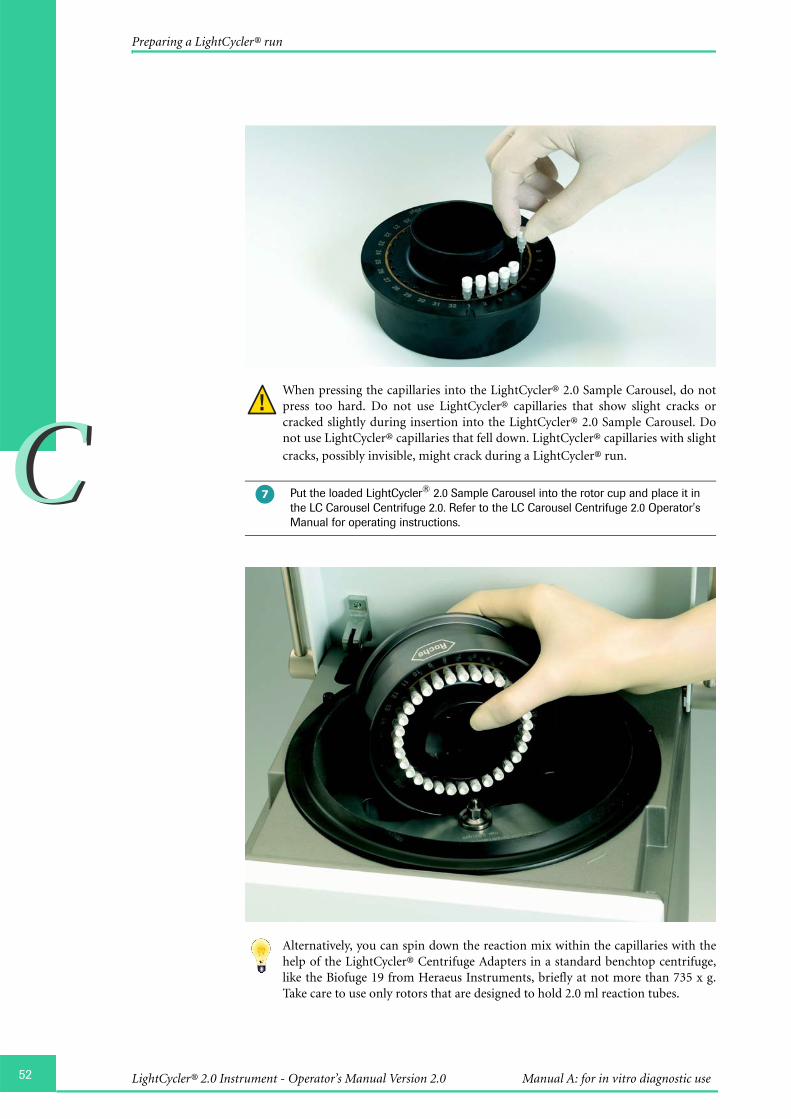
52
CC
Preparing a LightCycler® run
When pressing the capillaries into the LightCycler® 2.0 Sample Carousel, do notpress too hard. Do not use LightCycler® capillaries that show slight cracks orcracked slightly during insertion into the LightCycler® 2.0 Sample Carousel. Donot use LightCycler® capillaries that fell down. LightCycler® capillaries with slight
cracks, possibly invisible, might crack during a LightCycler® run.
Alternatively, you can spin down the reaction mix within the capillaries with thehelp of the LightCycler® Centrifuge Adapters in a standard benchtop centrifuge,like the Biofuge 19 from Heraeus Instruments, briefly at not more than 735 x g.Take care to use only rotors that are designed to hold 2.0 ml reaction tubes.
Put the loaded LightCycler® 2.0 Sample Carousel into the rotor cup and place it in the LC Carousel Centrifuge 2.0. Refer to the LC Carousel Centrifuge 2.0 Operator's Manual for operating instructions.
�
LightCycler® 2.0 Instrument - Operator’s Manual Version 2.0 Manual A: for in vitro diagnostic use

CC
Preparing a LightCycler® run
Before the LightCycler® 2.0 Sample Carousel is placed in the LightCycler® 2.0Instrument ensure that the thermal chamber is clean and free of any items whichcould interfere with the capillaries during the run. Cleaning instructions are
specified in Chapter E Maintenance.
Refer to Chapter E Maintenance for details on subsequent measures if capillarybreakage occurs.
Place the LightCycler® 2.0 Sample Carousel in the LightCycler® 2.0 Instrument. Ensure that the notch below sample position 1 on the LightCycler® 2.0 Sample Carousel locks into position with the pin on the thermal chamber as indicated in the upper picture. Check visually if the carousel is inserted correctly and fits perfectly in the thermal chamber as indicated in the lower picture.
Close the lid. You are now ready to start the run.
�
53Operation

54
CC
Abort a Run
4. Abort a Run
Refer to Chapter D Software for instructions on how to abort a run.
5. Shut-Down
To shut down the LightCycler® 2.0 Instrument proceed as follows:
To ensure that the lid is unlocked, complete or exit a run before shutting-down theLightCycler® 2.0 Instrument.
Exit the LightCycler® Software 4.05 and shut-down the computer.
Put the LightCycler® ON/OFF switch on the back of the instrument in the OFF position. To locate the ON/OFF switch refer to Chapter A Overview.
Switch off PC and printer.
�
�
�
LightCycler® 2.0 Instrument - Operator’s Manual Version 2.0 Manual A: for in vitro diagnostic use

Chapter D • Softwarecontains instructions for using Roche Macros.
Software
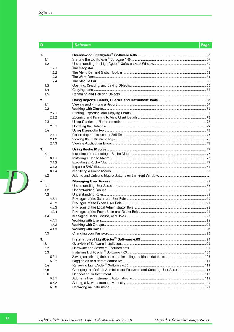
56
DD
LightCycler® 2.0 Instrument - Operator’s Manual Version 2.0 Manual A: for in vitro diagnostic use
1. Overview of LightCycler® Software 4.05 ..............................................................................................571.1 Starting the LightCycler® Software 4.05.......................................................................................................571.2 Understanding the LightCycler® Software 4.05 Window...................................................................... 60
1.2.1 The Navigator......................................................................................................................................................... 611.2.2 The Menu Bar and Global Toolbar ................................................................................................................. 621.2.3 The Work Pane....................................................................................................................................................... 641.2.4 The Module Bar......................................................................................................................................................65
1.3 Opening, Creating, and Saving Objects ....................................................................................................... 661.4 Copying Items ........................................................................................................................................................ 661.5 Renaming and Deleting Objects..................................................................................................................... 66
2. Using Reports, Charts, Queries and Instrument Tools ..................................................................672.1 Viewing and Printing a Report..........................................................................................................................672.2 Working with Charts............................................................................................................................................ 69
2.2.1 Printing, Exporting, and Copying Charts...................................................................................................... 692.2.2 Zooming and Panning to View Chart Details..............................................................................................72
2.3 Using Queries to Find Information..................................................................................................................732.3.1 Updating the Database .......................................................................................................................................74
2.4 Using Diagnostic Tools ........................................................................................................................................752.4.1 Performing an Instrument Self Test ................................................................................................................752.4.2 Viewing the Instrument Logs ............................................................................................................................752.4.3 Viewing Application Errors.................................................................................................................................76
3. Using Roche Macros........................................................................................................................................773.1 Installing and executing a Roche Macro......................................................................................................77
3.1.1 Installing a Roche Macro....................................................................................................................................773.1.2 Executing a Roche Macro ..................................................................................................................................783.1.3 Import a SAM file ................................................................................................................................................. 813.1.4 Modifying a Roche Macro..................................................................................................................................82
3.2 Adding and Deleting Macro Buttons on the Front Window......................................................................
4. Managing User Access ................................................................................................................................. 884.1 Understanding User Accounts ........................................................................................................................ 884.2 Understanding Groups ....................................................................................................................................... 894.3 Understanding Roles........................................................................................................................................... 89
4.3.1 Privileges of the Standard User Role ............................................................................................................ 904.3.2 Privileges of the Expert User Role .................................................................................................................. 914.3.3 Privileges of the Local Administrator Role ...................................................................................................924.3.4 Privileges of the Roche User and Roche Role ............................................................................................92
4.4 Managing Users, Groups, and Roles .............................................................................................................934.4.1 Working with Users.............................................................................................................................................. 944.4.2 Working with Groups .......................................................................................................................................... 964.4.3 Working with Roles...............................................................................................................................................97
4.5 Changing your Password................................................................................................................................... 98
5. Installation of LightCycler® Software 4.05 ......................................................................................... 995.1 Overview of Software Installation................................................................................................................... 995.2 Hardware and Software Requirements ........................................................................................................ 995.3 Installing LightCycler® Software 4.05......................................................................................................... 100
5.3.1 Saving an existing database and installing additional databases ................................................... 1055.3.2 Logging on to different databases............................................................................................................... 111
5.4 Removing LightCycler® Software 4.05 ....................................................................................................... 1135.5 Changing the Default Administrator Password and Creating User Accounts ............................ 1155.6 Connecting an Instrument .............................................................................................................................. 118
5.6.1 Adding a New Instrument Automatically .................................................................................................. 1185.6.2 Adding a New Instrument Manually ........................................................................................................... 1205.6.3 Removing an Instrument.................................................................................................................................. 121
D Software Page
Software

DD
Overview of LightCycler® Software 4.05
Starting the LightCycler® Software 4.05
Software
1. Overview of LightCycler® Software 4.05
This chapter provides a general introduction to the LightCycler® Software 4.05. Itincludes the following topics:
õ Starting the LightCycler® Software 4.05
õ Understanding the LightCycler® Software 4.05 window
õ Opening, creating, and saving objects
õ Renaming and deleting objects
õ Importing and exporting objects
1.1 Starting the LightCycler® Software 4.05
Follow the procedure below to start the software and open a demo experiment. The demoexperiment illustrates the features and components of the LightCycler® Software 4.05described in the rest of this chapter.
To start the LightCycler® Software 4.05 and view a demo experiment
The application displays the LightCycler® Software 4.05 window containing theNavigator on the left and a picture of a LightCycler® Instrument on the right. The activityof the buttons you see on the window depends on the role associated with your useraccount. For more information see chapter Managing User Access.
Double-click the LightCycler® Software 4.05 icon on the desktop.
In the Login dialog box, type your user name and password. (The initial password for the admin user is LightCycler01. You will be prompted to change the initial password upon your first login. For more information see Changing your Password.)
To connect to the database on the local computer, select LocalExor3 in the Log on to box.
Click Login.
�
�
�
�
57Software
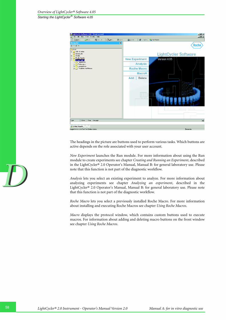
58
DD
Overview of LightCycler® Software 4.05
Starting the LightCycler® Software 4.05
The headings in the picture are buttons used to perform various tasks. Which buttons areactive depends on the role associated with your user account.
New Experiment launches the Run module. For more information about using the Runmodule to create experiments see chapter Creating and Running an Experiment, describedin the LightCycler® 2.0 Operator's Manual, Manual B: for general laboratory use. Pleasenote that this function is not part of the diagnostic workflow.
Analysis lets you select an existing experiment to analyze. For more information aboutanalyzing experiments see chapter Analyzing an experiment, described in theLightCycler® 2.0 Operator's Manual, Manual B: for general laboratory use. Please notethat this function is not part of the diagnostic workflow.
Roche Macro lets you select a previously installed Roche Macro. For more informationabout installing and executing Roche Macros see chapter Using Roche Macros.
Macro displays the protocol window, which contains custom buttons used to executemacros. For information about adding and deleting macro buttons on the front windowsee chapter Using Roche Macros.
LightCycler® 2.0 Instrument - Operator’s Manual Version 2.0 Manual A: for in vitro diagnostic use

DD
Overview of LightCycler® Software 4.05
Starting the LightCycler® Software 4.05
To open a demo experiment, in the Navigator, click the plus sign (+) next to each item in the path Roche\Experiments\Demo Experiments\.
Double-click any of the experiment names to open the experiment in the LightCycler® Software 4.05 window. The summary information for the experiment is displayed in the main window.
Select the Raw Data tab. The tab contains a list of samples and charts of experiment data.
To learn more about the LightCycler® Software 4.05 window, refer to the next section.
To close an experiment select Close from the File menu or click the X in the upper right corner of the current experiment window.
To exit the software, select Exit from the File menu or click the X in the upper right corner of the main window.
�
�
�
�
�
59Software
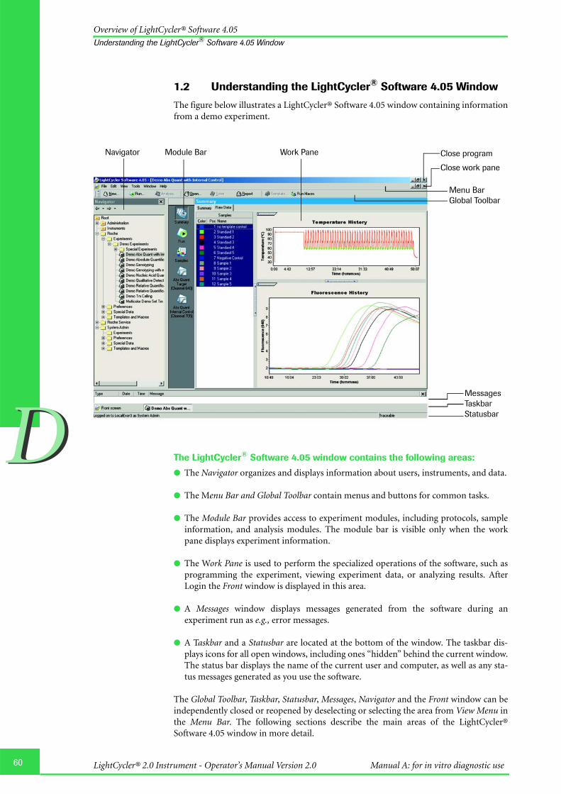
60
DD
Overview of LightCycler® Software 4.05
Understanding the LightCycler® Software 4.05 Window
1.2 Understanding the LightCycler® Software 4.05 Window
The figure below illustrates a LightCycler® Software 4.05 window containing informationfrom a demo experiment.
The LightCycler® Software 4.05 window contains the following areas:
õ The Navigator organizes and displays information about users, instruments, and data.
õ The Menu Bar and Global Toolbar contain menus and buttons for common tasks.
õ The Module Bar provides access to experiment modules, including protocols, sampleinformation, and analysis modules. The module bar is visible only when the workpane displays experiment information.
õ The Work Pane is used to perform the specialized operations of the software, such asprogramming the experiment, viewing experiment data, or analyzing results. AfterLogin the Front window is displayed in this area.
õ A Messages window displays messages generated from the software during anexperiment run as e.g., error messages.
õ A Taskbar and a Statusbar are located at the bottom of the window. The taskbar dis-plays icons for all open windows, including ones “hidden” behind the current window.The status bar displays the name of the current user and computer, as well as any sta-tus messages generated as you use the software.
The Global Toolbar, Taskbar, Statusbar, Messages, Navigator and the Front window can beindependently closed or reopened by deselecting or selecting the area from View Menu inthe Menu Bar. The following sections describe the main areas of the LightCycler®Software 4.05 window in more detail.
MessagesTaskbarStatusbar
Menu BarGlobal Toolbar
Close program
Close work pane
Navigator Module Bar Work Pane
LightCycler® 2.0 Instrument - Operator’s Manual Version 2.0 Manual A: for in vitro diagnostic use
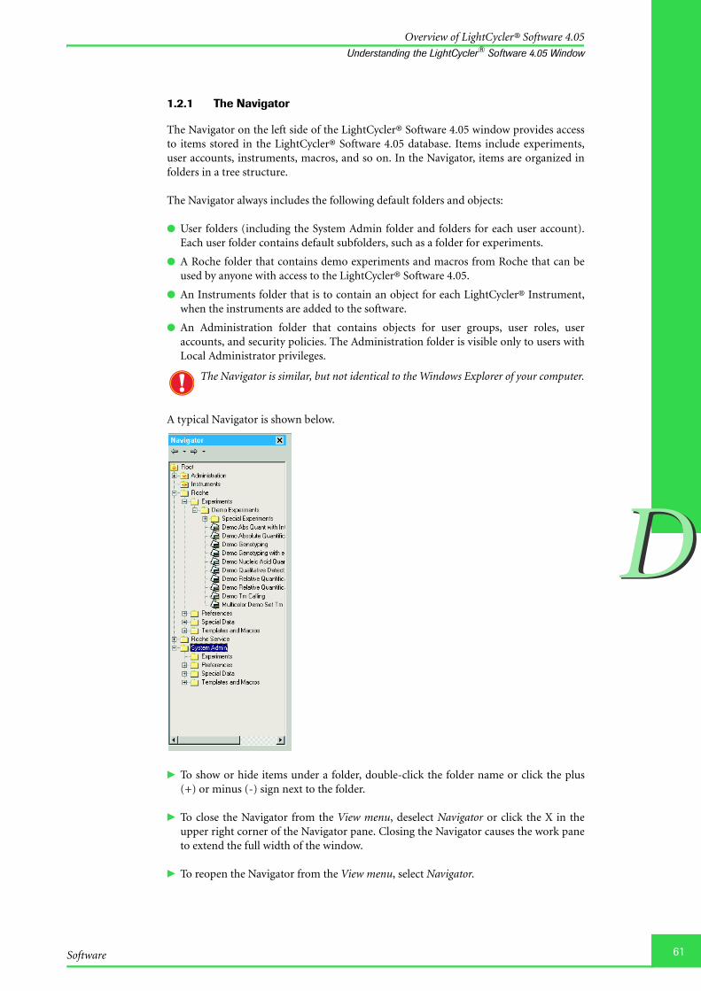
DD
Overview of LightCycler® Software 4.05
Understanding the LightCycler® Software 4.05 Window
1.2.1 The Navigator
The Navigator on the left side of the LightCycler® Software 4.05 window provides accessto items stored in the LightCycler® Software 4.05 database. Items include experiments,user accounts, instruments, macros, and so on. In the Navigator, items are organized infolders in a tree structure.
The Navigator always includes the following default folders and objects:
õ User folders (including the System Admin folder and folders for each user account).Each user folder contains default subfolders, such as a folder for experiments.
õ A Roche folder that contains demo experiments and macros from Roche that can beused by anyone with access to the LightCycler® Software 4.05.
õ An Instruments folder that is to contain an object for each LightCycler® Instrument,when the instruments are added to the software.
õ An Administration folder that contains objects for user groups, user roles, useraccounts, and security policies. The Administration folder is visible only to users withLocal Administrator privileges.
The Navigator is similar, but not identical to the Windows Explorer of your computer.
A typical Navigator is shown below.
� To show or hide items under a folder, double-click the folder name or click the plus(+) or minus (-) sign next to the folder.
� To close the Navigator from the View menu, deselect Navigator or click the X in theupper right corner of the Navigator pane. Closing the Navigator causes the work paneto extend the full width of the window.
� To reopen the Navigator from the View menu, select Navigator.
61Software

62
DD
Overview of LightCycler® Software 4.05
Understanding the LightCycler® Software 4.05 Window
1.2.2 The Menu Bar and Global Toolbar
Use the Menu Bar and Global Toolbar (along with the Navigator) to create and managethe LightCycler® objects. The buttons provide quick access to many commands that areavailable in the menus.
Using menus
File menu
õ Create (New), open, save, and close objects
õ View the revision history for an object currently open in the LightCycler® Software4.05 window
õ Log out of the current session
õ Import or export files
õ Print an experiment report or print the current window
õ Exit the software
Edit menu
õ Cut, copy, and paste data in the work pane
õ Select all items
View menu
õ Display or hide the following parts of the LightCycler® Software 4.05 window: theGlobal Toolbar, Taskbar, Statusbar, Messages and Navigator
õ Display the Front window (the window you see when you start LightCycler® Software4.05) in the work pane
Tools menu
õ Change your password
õ Open the user management tool (used to create, delete, and edit users, groups, androles)
õ Run Roche Macros
õ Manage instrument information
õ View database status
õ Obligate users to enter a Carousel ID in the Policy editor (for local administratorsonly)
õ Install a Roche Macro
Window menu
õ Close, minimize, and arrange windows when multiple windows are open in the workpane
õ Select an open window to make it the active window (The bottom of the Windowmenu displays a list of all currently open windows. The active window is checked.)
Help menu
õ Display an online version of an LightCycler® Software 4.05 Operator's Manual
õ View version and others as e.g., copyright information about the software
LightCycler® 2.0 Instrument - Operator’s Manual Version 2.0 Manual A: for in vitro diagnostic use
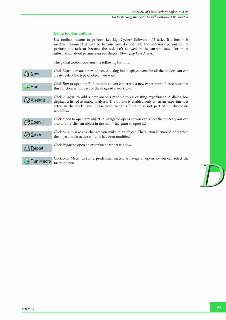
DD
Overview of LightCycler® Software 4.05
Understanding the LightCycler® Software 4.05 Window
Using toolbar buttons
Use toolbar buttons to perform key LightCycler® Software 4.05 tasks. If a button isinactive (dimmed) it may be because you do not have the necessary permission toperform the task or because the task isn't allowed in the current state. For moreinformation about permissions see chapter Managing User Access.
The global toolbar contains the following buttons:
Click New to create a new object. A dialog box displays icons for all the objects you cancreate. Select the type of object you want.
Click Run to open the Run module so you can create a new experiment. Please note thatthis function is not part of the diagnostic workflow.
Click Analysis to add a new analysis module to an existing experiment. A dialog boxdisplays a list of available analyses. The button is enabled only when an experiment isactive in the work pane. Please note that this function is not part of the diagnosticworkflow.
Click Open to open any object. A navigator opens so you can select the object. (You canalso double-click an object in the main Navigator to open it.)
Click Save to save any changes you make to an object. The button is enabled only whenthe object in the active window has been modified.
Click Report to open an experiment report window.
Click Run Macro to run a predefined macro. A navigator opens so you can select themacro to run.
63Software

64
DD
Overview of LightCycler® Software 4.05
Understanding the LightCycler® Software 4.05 Window
1.2.3 The Work Pane
The LightCycler® Software Work Pane contains information specific to the operation youare performing. For example, when you run an experiment, the work pane displays a runwindow that includes a tab for the experiment protocol, a tab that displays the currentdata being generated, and a tab for experiment notes.
The work pane is designed to allow multiple open windows. A label for each open win-dow is visible in the taskbar at the bottom of the window. The work pane illustratedbelow displays two windows: the Front screen and a window for an experiment.
To view and size windows in the work pane
� Use the mouse pointer to drag a window’s edge or corner to resize the window.
� Use the buttons in the upper right corner of each window to maximize, min-imize, restore, or close the window.
� Use the Window menu to close, minimize, or arrange the windows.
� Click a label in the taskbar to restore a minimized window or to bring a hidden win-dow to the front.
To size individual sections of windows
� Drag the horizontal borders between sections to size them.
� Click the handle on the border of a section to hide or show/expand the section.
LightCycler® 2.0 Instrument - Operator’s Manual Version 2.0 Manual A: for in vitro diagnostic use

DD
Overview of LightCycler® Software 4.05
Understanding the LightCycler® Software 4.05 Window
1.2.4 The Module Bar
The module bar contains icons for experiment components. The menu is visible only
when an experiment is open. The module bar displays the following icons:
To use the module bar
� Click an icon to open the related experiment module or use the keyboard shortcut forthe icon, Ctrl-Shift-n, where n is the number of the icon counting from the top. Forexample, the Samples icon is always third in the list of icons, so to open the SampleEditor module, press Ctrl-Shift-3. (Hold the mouse pointer over an icon to see thename of the related module and the keyboard shortcut for opening the module.)
� Click Analysis of the toolbar or right-click the module bar and select New Analysis toadd an analysis module to an experiment.
� Right-click an analysis icon to display a menu that lets you � Remove the current analysis from the experiment.� Rename the current analysis. Renaming is helpful if you have more than one
analysis of the same type, such as two absolute quantification analyses.
Summary icon opens the Summary module of the experiment, which contains informa-tion about the experiment (such as name, date, and owner) and charts of data generatedby the experiment.
Run icon opens the Run module, which includes the details of the experiment protocol,charts of experiment data, and notes entered by the person running the experiment.
Samples icon opens the Sample Editor, which contains sample information needed forthe experiment.
Analysis icons open the associated analysis module. When an analysis is added to anexperiment, an analysis icon is added to the module bar. This example shows an icon foran Absolute Quantification analysis.
65Software

66
DD
Overview of LightCycler® Software 4.05
Opening, Creating, and Saving Objects
1.3 Opening, Creating, and Saving Objects
You can use the Navigator and the toolbar menus and buttons to open, create, or save theLightCycler® objects. (The objects you are allowed to create depend on your user status.)
To open an existing object
Double-click the object name in the Navigator or click on the toolbar or selectOpen from the File menu. A small navigator opens in a dialog box. Select the objectname, then click OK. The information for the object is displayed in the work pane.
To create and save a new object
� Click on the toolbar, or from the File menu select New. A dialog box openscontaining icons for the LightCycler® objects. Select the icon for the object you want,then click OK.
� Enter information in the work pane to define the object.
� Click on the toolbar, or from the File menu, select Save.
1.4 Copying Items
You can copy any item (except for experiment objects) from another user’s folder intoyour own folder or subfolder. (However, your user role may limit which other users’folders are visible to you.)
Once the item is in your own folder, it becomes your item and you can modify it asnecessary (subject to the limitations of your user role).
To copy items from another user’s folder
� Right-click the item you want to copy in the Navigator, then select Copy. A smallnavigator dialog opens.
� Select a target folder enter a new name for the item if desired, then click OK.
1.5 Renaming and Deleting Objects
Your user role determines which objects you can rename or delete. For more informationabout user roles see chapter Managing User Access.
To rename an object
Right-click the object in the Navigator, then select Rename or select the object in the Nav-igator, then press F2. The object name becomes an editable text box. Type in the newname of the object.
To delete an object
Right-click the object in the Navigator, then select Delete. Or select the object, then pressthe keyboard Delete key. Click OK to confirm the deletion. You cannot delete anexperiment object.
LightCycler® 2.0 Instrument - Operator’s Manual Version 2.0 Manual A: for in vitro diagnostic use

DD
Using Reports, Charts, Queries and Instrument Tools
Viewing and Printing a Report
2. Using Reports, Charts, Queries and Instrument Tools
LightCycler® Software 4.05 includes the following tools and commands:
õ A report generator used to generate reports that include experiment information andanalysis results; for more information see Viewing and Printing a Report below.
õ A tool to export and print charts to various graphic formats and copy and paste chartimages and data; for more information see Working with charts below.
õ A query tool used to find objects in the database; for more information see Usingqueries to find information below.
õ Instrument and application diagnostic tools, including an instrument self test, errorand operation logs. For more information see Using diagnostic tools below.
2.1 Viewing and Printing a Report
After the Roche Macro run is finished, LightCycler® Software 4.05 generates and displaysa report containing experiment information and analysis results.
67Software
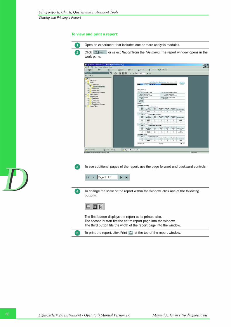
68
DD
Using Reports, Charts, Queries and Instrument Tools
Viewing and Printing a Report
To view and print a report:
Open an experiment that includes one or more analysis modules.
Click , or select Report from the File menu. The report window opens in the work pane.
To see additional pages of the report, use the page forward and backward controls:
To change the scale of the report within the window, click one of the following buttons:
The first button displays the report at its printed size.The second button fits the entire report page into the window.The third button fits the width of the report page into the window.
To print the report, click Print at the top of the report window.
�
�
�
�
�
LightCycler® 2.0 Instrument - Operator’s Manual Version 2.0 Manual A: for in vitro diagnostic use

DD
Using Reports, Charts, Queries and Instrument Tools
Working with Charts
2.2 Working with Charts
The LightCycler® Software 4.05 generates many kinds of charts during and after anexperiment run and as part of an experiment analysis. You can print charts, export chartsto various graphic formats, and copy and paste chart images and chart data. The chartsinclude a zoom and a pan function, so you can enlarge details of a chart and move thechart left or right.
2.2.1 Printing, Exporting, and Copying Charts
You can print any chart displayed in the LightCycler® Software 4.05. You can also exportthe chart image and the chart data separately, or copy and paste the image and the dataseparately into other programs.
To print a chart:
Display the chart you want to print.
Right-click within the chart boundaries, then select Print. A setup window is displayed.
To change the graph margins, and thereby the size of the graph, click and drag the gray margin lines that surround the graph image.
You can resize the dialog box to make it easier to adjust the graph margins.
If necessary, select a printer. (Your default Windows printer is selected by default).
To change printer configuration options, click Setup. A standard Windows printer setup dialog box is displayed. Enter the necessary information, then click OK.
Select the paper orientation (Portrait or Landscape) and click Print.
�
�
�
�
�
�
69Software

70
DD
Using Reports, Charts, Queries and Instrument Tools
Working with Charts
To export a chart image:
Display the chart you want to export.
Right-click within the chart boundaries, then select Export. An Export dialog box opens.
On the Picture tab, under Format, select the graphic format in which you want to export the chart.
If an Options tab is displayed (on the right), select conversion options as needed. (The tab is not displayed for all graphic formats. If the tab is displayed, the options vary, depending on the format you selected.)
To change the size of the exported image, select the Size tab, then enter the new width and height values. Select Keep aspect ratio if you want to maintain the proportions of the chart.
Click (to the right of the Filename box), to open a Save As dialog box.
Browse to the location where you want to save the exported chart image, enter a name for the image, then click Save.
Click Export to export the chart.
�
�
�
�
�
�
�
�
LightCycler® 2.0 Instrument - Operator’s Manual Version 2.0 Manual A: for in vitro diagnostic use

DD
Using Reports, Charts, Queries and Instrument Tools
Working with Charts
To export chart data:
To copy a chart image or chart data:
Display the chart containing the data you want to export.
Right-click within the chart boundaries, then select Export. An Export dialog box opens.
Select the Data tab.
In the Series box, select the data item you want to export. The items vary, depending on the type of chart.
In the Include box, select the text labels to export with the data.
In the Format box, select a format for the exported data.
If you selected Text as the format, select a delimiter in the Delimiter box.
Click (to the right of the Filename box), to open a Save As dialog box.
Browse to the location where you want to save the exported data, enter a name for the data file, then click Save.
Click Export to export the data.
Display the chart you want to copy.
Right-click within the chart boundaries, then select Copy to clipboard. The chart is saved as a bitmap and the data is saved as text.
To paste the chart image, open a graphics application such as Paint, then press Ctrl-V.
To paste the chart data, open a text editor such as Notepad, then press Ctrl-V.
�
�
�
�
�
�
�
�
�
�
�
�
�
71Software

72
DD
Using Reports, Charts, Queries and Instrument Tools
Working with Charts
2.2.2 Zooming and Panning to View Chart Details
You can enlarge a portion of a chart as many times as necessary to view important details.If you use a 3-button mouse, you can shift the chart in any direction to view details thatare outside the window. Follow the procedures below to enlarge chart details (zoom) orto move a chart (pan).
To zoom:
To pan:
If portions of the chart disappear off the window, use the middle mouse button to clickthe chart, then drag the chart until the portion you want to see is in view.
You may be able to configure a 2-button mouse so that clicking both buttons at thesame time equals the functionality of a middle button. See your system administratoror refer to the device driver instructions that came with your mouse.
Place the cursor above and to the left of the chart area you want to enlarge.
Click and drag the mouse pointer down and to the right. (The pointer changes to a rectangle.) Release the mouse button when the rectangle covers the area you want to enlarge. The area within the rectangle is enlarged to fill the work pane.
Repeat step 2 as often as necessary until the chart details are as large as you want.
To restore the chart to its original size, click and drag the mouse pointer up and to the left. (You need to do this only once to restore the chart to its original size.)
�
�
�
�
LightCycler® 2.0 Instrument - Operator’s Manual Version 2.0 Manual A: for in vitro diagnostic use

DD
Using Reports, Charts, Queries and Instrument Tools
Using Queries to Find Information
2.3 Using Queries to Find Information
The LightCycler® Software 4.05 includes a query tool you can use to retrieve experimentsand other objects stored in the LightCycler® Software 4.05 database.
To create and execute a query:
Click New, select the Query icon, then click OK. A query window opens in the LightCycler® Software 4.05 work pane.
In the Object Type box, select the type of object to look for, such as Experiment.
(Optional) Enter the name of the item to search for or the owner of the item, if known.
Select Modified Date or Creation Date to specify which date you want to use in the query.
Select a date range. You can specify the number of months or days before the current date to search, or you can select a beginning and ending date in the past.
To refine the search, click Advanced, then enter additional search criteria. The available options in the Search Options tab depend on the type of object you are looking for. You can also select a certain folder in the Search Folders tab. Check the Scan Sub-folders box to include subdirectories of the directory.
Click Search. Results are displayed to the right of the search criteria. The results include the following:Object name Object typeDate the object was createdDate the object was last modified
If an error message is displayed stating that the query engine needs to be updated, you must update the database. If you have Local Administrator privile-ges see “Updating the database” below for instructions. Otherwise, see your system administrator.
To open an object, double-click the object name.
To save the query, click Save. A small navigator opens. Select a location, enter a query name, then click OK.
To close the search window, click Close from the File menu or click the X in the upper right corner of this window.
�
�
�
�
�
�
�
�
�
73Software

74
DD
Using Reports, Charts, Queries and Instrument Tools
Using Queries to Find Information
To execute a saved query:
2.3.1 Updating the Database
Occasionally, the LightCycler® Software 4.05 database may need to be updated, forexample if a LightCycler® Software 4.05 release includes new query search parameters.When this happens, the software displays an error message stating that the query engineneeds to be updated.
If your user account is assigned the Local Administrator role, follow the steps below toupdate the database. Otherwise, contact your system administrator.
Prerequisites:
õ You must have Local Administrator privileges to update the database.
õ There must be no other users using the database.
To update the database:
Find the query you want in the Navigator. The default location for saved queries is in the Query folder under the Special Data folder for your user account.
Double-click the query name to open the query in the Query window.
In the Query window, click Search to execute the query.
From the Tools menu, select Database Status.
Check the list of users in the Logged In Users tab. If other users are logged in, you cannot update the database. (The button on the Query Engine tab is inactive.)
If no other users are logged in, select the Query Engine tab.
Click Update. You are reminded that the update will take several minutes.
Click Yes to clear the message and continue. After the database is updated, a message states that the update is complete.
Click OK to clear the message. The Query Engine tab states that the query engine is now up to date. A Reindex button is displayed.
Click Reindex. You are reminded that the reindex will take several minutes.
Click Yes to clear the message and continue. After the database is reindexed, a message states that the reindex is complete.
Click OK to clear the message.
Close the Database Status dialog box.
�
�
�
�
�
�
�
�
�
�
�
�
LightCycler® 2.0 Instrument - Operator’s Manual Version 2.0 Manual A: for in vitro diagnostic use

DD
Using Reports, Charts, Queries and Instrument Tools
Using Diagnostic Tools
2.4 Using Diagnostic Tools
The LightCycler® Software 4.05 includes the following diagnostic tools used to monitorthe LightCycler® 2.0 Instrument’s performance:
õ A button used to perform an instrument self test
õ Instrument logs
2.4.1 Performing an Instrument Self Test
The instrument self test checks all instrument functionality, such as heating to the correcttemperature and rotating the carousel.
To perform an instrument self test:
If an error occurs, the self test displays an error message and logs the error to theinstrument’s error log. See the next section for information about the error log.
If there are no errors, the software displays “Self test passed” when the self test is finished.
Do not start other software applications when performing an instrument self test.
It is recommended to perform an instrument self test once a day before starting theLightCycler® runs.
2.4.2 Viewing the Instrument Logs
The LightCycler® Software 4.05 generates an Error Log and an Operation Log, which areboth located on the Instrument Logs tab of the Instrument window. You do not need touse these logs in normal instrument operation. The logs contain information that may beneeded by support representatives if there is an instrument problem. In case of an instru-ment problem, it may be necessary to export a System Query Data object including boththe Error Log and Operation Log, to forward to your support representative.
To view instrument logs:
In the Instruments folder of the Navigator, double-click the instrument name to open the Instrument window.
Click Self Test on the instrument toolbar.The software is locked while the self test is performed.
In the Instruments folder of the Navigator, double-click the instrument name to open the Instrument window.
Select the Instrument Logs tab.
The Total Runs and Total Measurements fields at the top of the tab indicate the total runs completed and the total number of individual fluorescence measurements taken since the instrument came from the factory. The fields are illustrated below.
�
�
�
�
�
75Software

76
DD
Using Reports, Charts, Queries and Instrument Tools
Using Diagnostic Tools
To export a System Data Query object:
2.4.3 Viewing Application Errors
Error messages generated by the LightCycler® Software 4.05 are displayed in a messagepane at the bottom of the LightCycler® Software 4.05 window. You can choose to displayor hide the message pane.
To display or hide the messages pane:
� From the View menu select or deselect Messages.
Each error entry includes the date and time of the error, and the error message.
Select the Operation Log tab or the Error Log tab to view the related log. The logs contain the following information:�The Operation Log displays a list of the last 10 runs on the instrument. The log
includes basic information about each run, such as the run name and date. It also lists the total number of runs and the total number of fluorescence measurements on the instrument as of the end of the run. A Comm Log button is displayed at the end of each row. Click Comm Log to display a list of all the commands executed in this run.
�The Error Log lists all errors that have occurred on the instrument since the instrument came from the factory. Each error includes an error number, the date, and a remark (the error message). The error log information may be requested by a support representative, if there is an instrument problem.
In LightCycler® Software 4.05 open the experiment you want to export.
From the File menu, select Export.
Navigate to a location to save the exported file, select System Query Data as the file type, enter a file name, then click Save. The file is saved with an .ixo extension.
�
�
�
�
LightCycler® 2.0 Instrument - Operator’s Manual Version 2.0 Manual A: for in vitro diagnostic use

DD
Using Roche Macros
Installing and executing a Roche Macro
3. Using Roche Macros
This chapter explains how to install and execute a Roche Macro, and how to add anddelete macro buttons from the front window.
3.1 Installing and executing a Roche Macro
A Roche Macro is an experiment kit including run protocol, analysis modules and report.It includes templates for all the components of the experiment and a program called awizard used to run the Roche Macro. When you execute a Roche Macro, the wizardguides you through the process of choosing an instrument, and then applies the experi-ment protocol, starts the experiment run, and after the run is finished, adds the analysismodules to the experiment.
To execute a Roche Macro you can use the Roche Macro button on the front screen. Youcan also link the Roche Macro with a macro button in the Macro menu on theLightCycler® Software 4.05 front screen. Clicking the button executes the Roche Macro.
3.1.1 Installing a Roche Macro
Assure to be logged on to the Traceable database. For details refer to To log on to a local computer in chapter Changing the Default Administrator Password and Creating User Accounts.
From the Tools menu select Install Kit.
The Kit Installer window opens.
Enter the path of the *.lckit or click , and then navigate to the location on your computer. Click Install.
The Roche Macro is automatically installed in the Roche/Templates and Macros folder.
�
�
�
�
�
77Software

78
DD
Using Roche Macros
Installing and executing a Roche Macro
3.1.2 Executing a Roche Macro
When you execute a Roche Macro, the LightCycler® Software 4.05 automatically launchesa wizard to guide you through the process of using the Roche Macro to run theexperiment. As you run the Roche Macro, you can edit the sample information.
To execute a Roche Macro:
Assure to be logged on to the Traceable database. For details refer to To log on to a local computer in chapter Changing the Default Administrator Password and Creating User Accounts.
Click Roche Macro on the Front Screen.
The Scan Catalog/Lot Number window appears. Enter the Assay catalog number of the kit you use and enter the corresponding Assay lot number. You can also scan the catalog and lot number from the kit (printed on the back side of the respective package insert) with the barcode reader. Click OK.
In case the software finds more than one macro matching your entry, a list of the available macros is displayed. Select the appropriate macro from this list.
The software confirms the availability of the macro. Click Yes to continue.
The Experiment Kit Wizard opens. Click Next.
�
�
�
�
�
LightCycler® 2.0 Instrument - Operator’s Manual Version 2.0 Manual A: for in vitro diagnostic use

DD
Using Roche Macros
Installing and executing a Roche Macro
The wizard prompts you to select an instrument. Check the Perform self test box if you want to perform an instrument self test before running the experiment. Click Next.
Select a folder and enter a name for the experiment.
The experiment is ready to run. Before starting the run, edit the sample information as necessary. When finished, click Start Run.
�
�
�
79Software

80
DD
Using Roche Macros
Installing and executing a Roche Macro
It is possible to stop a running LightCycler® experiment by clicking Abort Run.
This will lead to a loss of data of the aborted experiment.
If you abort a run, the instrument may be hot. Before you open the lid, wait until theinstrument has cooled down.
Additional software must not be installed on the LightCycler® 2.0 workstation.Installation of additional software contains the risk to interfere with LightCycler®Software 4.05 and may affect result security.
If you make modifications to an experiment after you have started the run you will beprompted to enter the reason for your changes in the Change Log window. This alsoapplies to modifications of the experiment since the last save action. Previously savedversions of the experiment then become a read-only version and can be viewed in theFile menu under Revisions.
After the run is finished, the report is displayed. You can switch to the analysis by clicking the corresponding icon in the taskbar.
LightCycler® 2.0 Instrument - Operator’s Manual Version 2.0 Manual A: for in vitro diagnostic use

DD
Using Roche Macros
Installing and executing a Roche Macro
3.1.3 Import a SAM file
You can import a MPLC SAM file into a new experiment, using the Import SAM buttonin the LightCycler® Software 4.05 Sample Editor of an opened new experiment.
To import a SAM file:
Do not change the SAM file manually.
To import a MagNA Pure LC file containing the sample information of a MagNA Pure nucleic acid isolation open the Sample Editor by clicking Samples in the module bar.
Click Import SAM in the toolbar of the workpane, find and select the SAM file, then click Open or read the barcode of your SAM file generated by your MagNA Pure LC instrument with a barcode reader.
Importing a SAM file is only possible before a run has started.
If you need to start over, click Reset Samples. You are prompted to confirm resetting the values. Click OK. Resetting the samples leaves the same number of samples, but resets all sample information to the default values and resets any analysis-specific sample editor tabs to their default values.
When finished, click Save in the global toolbar to save the sample information with the experiment.
�
�
�
�
81Software

82
DD
Using Roche Macros
Installing and executing a Roche Macro
3.1.4 Modifying a Roche Macro
The report page header includes the seal status of the experiment i.e., once the userchanges any of the Roche Macro settings, the report seal is broken and the following lineis displayed above the experiment name: User Developed or Modified Test Method.
Changes that cause the report seal to be broken:
Run programming
� Default channel
� Seek temperature
� Instrument type
� Capillary size
� Add or delete a program
� Program name
� Number of cycles
� Analysis mode
� Add or delete a temperature target
� Target temperature
� Hold time
� Ramp rate
� Secondary target temperature
� Step size
� Step delay
� Acquisition mode
� Automatically selected color compensation object
LightCycler® 2.0 Instrument - Operator’s Manual Version 2.0 Manual A: for in vitro diagnostic use

DD
Using Roche Macros
Installing and executing a Roche Macro
Sample editor-general:
� Selected analysis types
� Selected channels
Capillary View sample editor:
� Subsequent change of assay catalog number
� Subsequent change of assay lot number
� Color compensation ID
� Replicate information
Absolute Quantification sample editor:
� Enable controls selection status
� Unit entry
� Target name
� Sample type
� Standard concentration
� Cp low and Cp high
� Concentration low and concentration high
Relative Quantification – Monocolor sample editor:
� Target name
� Sample type
� Standard concentration
� Cp low and Cp high
Relative Quantification – Dual Color sample editor:
� Target name
� Sample type
� Standard concentration
� Cp low and Cp high
Qualitative Detection sample editor:
� Enable controls selection status
� Target name
� Sample type
� Cp low and cp high
Tm Calling sample editor:
� Target name
� Selected Tm calibrators
� Expected Tm
83Software

84
DD
Using Roche Macros
Installing and executing a Roche Macro
Genotyping sample editor:
� Target name
� Sample type
� Genotype
Nucleic Acid Quantification sample editor:
� Target name
� Sample type
� Standard concentration
Color compensation sample editor:
� Dominant channel
Analyses – general:
� Add or delete an analysis
� Analysis name
Absolute Quantification analysis:
� Channel nominator
� Channel denominator
� Automatically selected color compensation object, including selected channels
� Program used
� Standard curve used
� Method
� For Fit Points method:
� Selected background correction� Selected noise band method and value� Number of fit points� Minimize error selection� Threshold value
Relative Quantification – Monocolor analysis:
� Add or delete a group
� Group name
� Channel nominator
� Channel denominator
� Automatically selected color compensation object, including selected channels
� Program used
� Efficiency correction method and standard curve used
� Selected reference experiment
� Add results sets
� Correction factor
� Multiplication factor
LightCycler® 2.0 Instrument - Operator’s Manual Version 2.0 Manual A: for in vitro diagnostic use

DD
Using Roche Macros
Installing and executing a Roche Macro
Qualitative Detection analysis:
� Channel nominator
� Channel denominator
� Automatically selected color compensation object including selected channels
� Program used
Manual Tm Calling analysis:
� Baseline
� Sample type
� Channel
� Run program
� Color compensation
� Changing to automated Tm calling analysis
Automated Tm Calling analysis:
� Channel nominator
� Channel denominator
� Automatically selected color compensation object including selected channels
� Program used
� Calculation mode (automatic, manual)
� For automated calculation:
� Sensitivity mode� Maximum number of peaks� Show shoulders� Add or delete a melting peak� Change of automatically calculated melting temperature
� For manual determination:
� Sample-specific background values
Genotyping analysis:
� Channel nominator
� Channel denominator
� Automatically selected color compensation object including selected channels
� Program used
� Grouping mode and used standard melting curve object
� Sensitivity mode
� Group name
� Score threshold
� Resolution threshold
� Minimum and maximum temperature
85Software

86
DD
Using Roche Macros
Installing and executing a Roche Macro
Nucleic Acid Quantification analysis:
� Channel nominator
� Channel denominator
� Program used
Changes that do not break the report seal:
� Instrument used
� Run notes
� Maximum seek position/sample count
� LC carousel ID
� MPLC batch ID
� Assay lot number, if empty in the Roche Macro
� Sample name
� Sample notes
� Analysis notes
� Relative Quantification result set name
� Number of manually determined melting peaks
� Sample specific background values for manual peak height determination if notdefined in the macro
� All display settings, such as:
� Absolute Quantification, Fit Points method: show fit points selection� Relative Quantification – Monocolor: chart selection in pairing tab� Relative Quantification – Dual Color: chart selections in target/reference and
pairing tab� Qualitative Detection: advanced result display� Tm Calling: Manual Tm display; result table columns� Color compensation: channel
� Manual Tm Calling analysis:
� Tm values� Number of Tm values
LightCycler® 2.0 Instrument - Operator’s Manual Version 2.0 Manual A: for in vitro diagnostic use

DD
Using Roche Macros
Adding and Deleting Macro Buttons on the Front Window
3.2 Adding and Deleting Macro Buttons on the Front Window
If you have installed Roche Macros, you can link each Roche Macro to a macro button onthe LightCycler® Software 4.05 Front window. Clicking the button runs the experimentkit wizard.
Then follow the instructions below to assign the Roche Macro to a button on the Frontwindow.
You can add and delete macro buttons no matter what role is associated with your useraccount.
To add a macro button:
To delete a macro button:
If the LightCycler® Software 4.05 Front window is not currently displayed, click Front in the taskbar or select it from the View menu to display the window.
Click Add. If Add is not visible on the window, click the arrow next to Macro to display Add / Delete.
The Select Macro/Kit dialog box opens, as shown below.
Find and select the experiment kit macro you want, then click Open.
A button labeled with the kit macro name is added to the window below Add / Delete.
To execute the kit macro, click the button.
If Delete is not visible below Macro on the LightCycler® Software 4.05 Front window, click the arrow next to Macro and click Delete.A list of all macro buttons is displayed.
Select the button to delete, then click OK.
The button is deleted from the window.Only the macro button is deleted from the window, not the macro itself.
�
�
�
�
�
�
�
�
�
87Software

88
DD
Managing User Access
Understanding User Accounts
4. Managing User Access
To use the LightCycler® Software 4.05, you must have a user account in the LightCycler®Software 4.05 database. User accounts have different levels of access to the software,depending on the role assigned to the account and the groups to which the accountbelongs.
This chapter explains the function of user accounts, roles, and groups, and explains howto manage them using the LightCycler® Software 4.05 User Management tool. Thechapter also explains how to change a user password.
Read this chapter if you are responsible for creating or modifying user accounts or if youwant to understand the privileges associated with your account. Read the section onpasswords if you need to change your password.
Your own user account must have the Local Administrator role to use the UserManagement tool.
4.1 Understanding User Accounts
A user account provides access to the LightCycler® Software 4.05. The user accountspecifies the user’s login name and password and defines the user’s level of access to thesoftware.
When you create a user account, you must assign it a role. The role determines the tasksthe user can perform using the software. For more information see Understanding rolesbelow. You can also add a user account to one or more groups. Users in the same grouphave access to each other’s objects. For more information see Understanding groupsbelow.
Each user account has a default folder in the LightCycler® Software 4.05 Navigator, withseveral default subfolders. The user’s default folder and subfolders cannot be deleted,renamed, or moved. However, each user can create additional folders underneath thedefault folders.
A user called System Admin is created automatically when LightCycler® Software 4.05 isinstalled. The System Admin user has the Local Administrator role and is used to createother user accounts. The System Admin account cannot be edited or disabled.
A user account once created cannot be edited or deleted, it can however be made inactive.An inactive user account cannot have a role and cannot be assigned to a group.
LightCycler® 2.0 Instrument - Operator’s Manual Version 2.0 Manual A: for in vitro diagnostic use

DD
Managing User Access
Understanding Groups
4.2 Understanding Groups
A group is a collection of user accounts. The members of a group have access to eachother’s objects; for example, they can open each other’s experiments.
If users belong to more than one group, they need only one group in common to haveaccess to each other’s objects. For example, if user Bob belongs to Groups A and B, whileuser Susan belongs to Groups B and C, both Bob and Susan have access to each other’sobjects because both are members of Group B.
The level of access a user has to another user’s objects is determined by the user’s ownrole. For example, if Bob has the Standard User role, he can open and execute Susan’sexperiments. If Susan has the Expert User’s role, she can open, execute, modify, or moveBob’s experiments. See the next section for more information about roles.
4.3 Understanding Roles
Each user account is assigned to one and only one role. The role determines the user’sprivileges. There are four roles:
õ Standard User
õ Expert User
õ Local Administrator
õ Roche User
Roles cannot be created or deleted, but certain access privileges can be enabled ordisabled for each role. For more information see Working with roles below.
89Software
90
DD
Managing User Access
Understanding Roles
4.3.1 Privileges of the Standard User Role
A Standard User has limited access to the LightCycler® Software 4.05. A Standard Usercan do the following:
� Install Roche macros to execute and analyze experiments.
� Modify, move, copy, and open or execute the user’s own objects. For experiments, thisincludes modifying sample names, target names, sample notes, analysis notes, and thesample count (before the run begins). The standard user can include or excludesamples from the experiment’s analysis only if enabled by the Local Administrator.
� Open and copy objects and execute macros owned by a Local Administrator or theRoche User.
� Open and copy objects and execute macros in other Standard Users’ and Expert Users’folders, if the other users are members of the same group as the Standard User.
A Standard User cannot do the following:
� Use the Run programming window to create experiment programs from scratch or torefine experiment programs.
� Add analyses to experiments.
� Use the analysis toolbar to modify analysis settings, such as program or colorcompensation.
� Create macros.
� Modify or move objects belonging to other users.
� View folders or objects belonging to users who are not in the same group as theStandard User.
� Delete, move, copy, or rename default folders (including the user’s own defaultfolders).
� Copy or rename any experiment object (including the user's own objects).
� Delete any object (including the user’s own objects).
LightCycler® 2.0 Instrument - Operator’s Manual Version 2.0 Manual A: for in vitro diagnostic use

DD
Managing User Access
Understanding Roles
4.3.2 Privileges of the Expert User Role
An Expert User can do the following:
� Install Roche Macros to execute and analyze experiments.
� Create all other objects and open, copy, execute, modify, and move any of the user’sown objects. For experiments, this includes modifying sample information, thesample count (before the run begins), adding an analysis to the experiment, includingand excluding samples from the analysis, and using the analysis toolbar to change anyof the analysis settings.
� Delete the user’s own objects and nondefault folders, if enabled by the LocalAdministrator (only possible if the folder does not contain any objects).
� Rename the user's own nondefault folders and objects.
� Open, copy, and execute objects owned by the Local Administrator or the Roche User.
� Open, copy, and execute objects owned by other Expert Users, if the other users are inthe same group as this user.
� Create, open, copy, execute, modify, delete, and move objects in a Standard User’sfolder, if the Standard User is in the same group as the Expert User.
An Expert User cannot do the following:
� Create, delete, move, modify, or rename objects belonging to the Local Administrator,the Roche User, or other Expert Users.
� See the folders or objects belonging to Standard and Expert Users who are not in thesame group as the user.
� Copy, delete or rename experiment objects (including the user's own experimentobjects).
� Delete, move, copy, or rename default folders (including the user’s own folders).
91Software

92
DD
Managing User Access
Understanding Roles
4.3.3 Privileges of the Local Administrator Role
A Local Administrator can do the following:
� Use the Run programming module to create and execute experiments. Please note thatthis function is not part of the diagnostic workflow.
� Install Roche Macros to execute and analyze experiments.
� Create all other objects and open, copy, execute, modify, delete, and move any of theuser’s own objects. (Modify rights include modifying sample information, adding ananalysis to the experiment, and using the analysis toolbar to change any of the analysissettings.)
� Open, execute and copy objects belonging to other Local Administrators.
� Open, execute, and delete objects in the Roche folder.
� Create, open, copy, execute, modify, delete, and move objects in folders belonging toStandard and Expert Users.
� Use the User Management tool to manage users and groups; for more information seeManaging users, groups, and roles below.
The Local Administrator cannot do the following:
� Modify or move objects in the Roche folder.
� Modify, move or delete objects owned by other Local Administrators; for example oneadministrator cannot copy objects into another administrator’s folder.
� Copy, delete or rename experiment objects (including the user's own experimentobjects).
� Delete, move, copy, or rename default folders (including the user’s own folders).
4.3.4 Privileges of the Roche User and Roche Role
The Roche User is a special, predefined user account that is assigned the Roche role.Neither the Roche User nor the Roche role is visible in the User Management tool. Onlyrepresentatives from Roche have the user name and password needed to log in as theRoche User.
The Roche User has access to the Roche folder, which contains objects, such asexperiment protocols and standard curves, supplied by Roche.
The Roche Role allows the Roche User to do the following:
� Create, modify, move, execute, copy, and delete items and subfolders in the Rochefolder.
� Create, modify, move, execute, copy, and delete subfolders and items belonging toother users, only if enabled by a Local Administrator.
The Roche User cannot do the following:
� Delete, move, copy, or rename the Roche folder or user's default folders.
LightCycler® 2.0 Instrument - Operator’s Manual Version 2.0 Manual A: for in vitro diagnostic use
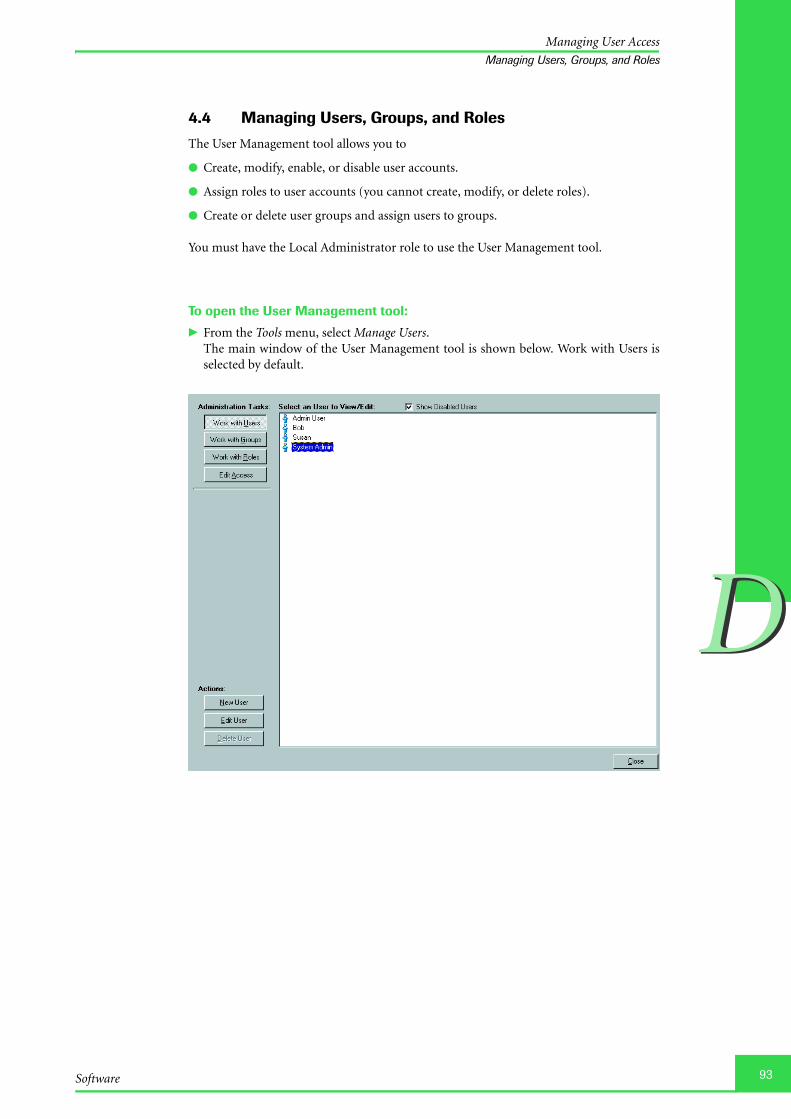
DD
Managing User Access
Managing Users, Groups, and Roles
4.4 Managing Users, Groups, and Roles
The User Management tool allows you to
õ Create, modify, enable, or disable user accounts.
õ Assign roles to user accounts (you cannot create, modify, or delete roles).
õ Create or delete user groups and assign users to groups.
You must have the Local Administrator role to use the User Management tool.
To open the User Management tool:
� From the Tools menu, select Manage Users.The main window of the User Management tool is shown below. Work with Users isselected by default.
93Software

94
DD
Managing User Access
Managing Users, Groups, and Roles
4.4.1 Working with Users
To create a new user account:
A default folder for the new user is added to the Navigator, and the user name is added tothe list of users in the \Administration\Users folder in the Navigator.
In the example above, four user accounts and two groups are listed in the Navigator. Theuser accounts are
Admin UserAmy ClaytonRichard DavisSystem Admin
Note that each user account has its own user folder.
The groups areLab1Lab2
In the User Management Tool, click Work with Users (if not already selected).
Click New User.
Enter the user’s full name, login name, and password and select a role for the user.
Check each group you want to add the user to. If no groups have been created, you can add the user when you create the group.
Click Done.
�
�
�
�
�
LightCycler® 2.0 Instrument - Operator’s Manual Version 2.0 Manual A: for in vitro diagnostic use

DD
Managing User Access
Managing Users, Groups, and Roles
To edit, enable, or disable a user account:
You cannot delete a user account.
In the User Management Tool, click Work with Users (if not already selected).
Select the user’s name in the right pane, then click Edit User.
The only information you can change is the password and the belonging to a certain group.
To disable the user account, select the Access Disabled check box; to reactivate a disabled account, clear the Access Disabled check box. You cannot disable the System Admin account.
When finished, click Done.
�
�
�
�
�
95Software

96
DD
Managing User Access
Managing Users, Groups, and Roles
4.4.2 Working with Groups
To create a new group:
The group is added to the Groups folder in the Navigator.
To edit a group:
To delete a group:
In the User Management Tool, click Work with Groups.
Click New Group.
Type a name for the group in the Group Name box.
To add users to the group, check the names of the users you want to add. (You can create a group without adding users.)
Click Done.
If you did not add users to the group, a message asks you to confirm saving the group without users. Click OK.
In the User Management Tool, click Work with Groups.
Select the group name in the right pane.
Click Edit Group.
Change the group name or select and deselect members of the group. You can also assign a group to a user when you edit the user account. See Working with Users above.
Click Done.
In the User Management Tool, click Work with Groups.
Select the group name in the right pane.
Click Delete Group. You are prompted to confirm the deletion.
Click Yes to delete the group.
�
�
�
�
�
�
�
�
�
�
�
�
�
�
�
LightCycler® 2.0 Instrument - Operator’s Manual Version 2.0 Manual A: for in vitro diagnostic use

DD
Managing User Access
Managing Users, Groups, and Roles
4.4.3 Working with Roles
You cannot create or delete roles, and you cannot change a user’s role assignment. Youcan modify certain access rights associated with the Standard User, Expert User, andRoche User roles. You cannot modify access rights of the Local Administrator role. Youcan also determine the time when a user is automatically logged off and determine themaximum login attempts before an access is disabled on entering an invalid password.
To determine conditions for access and modify a role's access rights:
In the User Management Tool, click Edit Access. The access window displays the available options.
Select or deselect the available options.
When finished, click Done.
�
�
�
97Software

98
DD
Managing User Access
Changing your Password
4.5 Changing your Password
When you are assigned an account on the LightCycler® Software 4.05 system, you receivean initial password you can use to log on to the LightCycler® Software 4.05 the first time(you will be prompted to change your initial password upon your first login). You canalso change your password whenever you want.
To change your password:
� From the Tools menu, select Change Password. The Password dialog box is displayed.
� Enter your current password in the Password box.
� Enter the new password in the New Password box and again in the Confirm Passwordbox. Click OK.
The password must contain at least six characters and contain one number and oneupper case character.
Passwords are case-sensitive.
Remember the password or keep it in a secure place. Do not share your password withothers.
LightCycler® 2.0 Instrument - Operator’s Manual Version 2.0 Manual A: for in vitro diagnostic use

DD
Installation of LightCycler® Software 4.05
Overview of Software Installation
5. Installation of LightCycler® Software 4.05
The complete LightCycler® software version 4.05 includes the LightCycler® Software 4.05application, a database, and an object server. If you have received a license to install theLightCycler® Software 4.05 also on a second or several other local computers e.g., for dataanalysis, follow the installation instructions below.
This chapter explains how to install LightCycler® Software 4.05. It includes the followingtopics:
õ Overview of software installation
õ Hardware and software requirements
õ Installing LightCycler® Software 4.05
õ Saving an existing database and installing additional databases
õ Removing LightCycler® Software 4.05
õ Changing the default administrator password and creating user accounts
5.1 Overview of Software Installation
LightCycler® Software 4.05 controls the LightCycler® 2.0 Instrument using informationyou provide in an experiment protocol. The LightCycler® Software 4.05 includes theLightCycler® Software 4.05 application, a database, and the database object server (called“Exor 3”), which communicates with the database. The software needs to be installed in alocal configuration.
In this configuration all the software components are installed on the LightCycler®computer connected to the LightCycler® 2.0 Instrument. Each instrument and computerfunction together as an independent system with its own database and its own set of useraccounts. Computers not connected to an instrument, which can be used for theLightCycler® Software 4.05 application tools but not for running an experiment, areindependent systems as well.
The LightCycler® 2.0 Instrument must not be connected to a network, althoughnetwork hardware is present. The connection to networks contains an inherent risk tobe infected through viruses and worms as well as targeted attacks through maliciousattackers through the network. Roche is not responsible for any damages caused byconnection of the LightCycler® 2.0 Instrument to a network by the customer.
5.2 Hardware and Software Requirements
For hard- and software requirements of the computer used to connect to theLightCycler® 2.0 Instrument or to launch the LightCycler® Software 4.05 for dataanalysis, please refer to chapter B System Description.
99Software

100
DD
Installation of LightCycler® Software 4.05
Installing LightCycler® Software 4.05
5.3 Installing LightCycler® Software 4.05
Insert the LightCycler® Software 4.05 CD. Double-click LightCycler_Software_405_Setup.exe, if installation doesn’t start automatically. The installation process transfers files, extracts the files, and then prepares the installation wizard. You are prompted to agree to the license conditions. Click Yes.
The InstallShield Wizard opens. Click Next.
�
�
LightCycler® 2.0 Instrument - Operator’s Manual Version 2.0 Manual A: for in vitro diagnostic use

DD
Installation of LightCycler® Software 4.05
Installing LightCycler® Software 4.05
Select the default settings to install the database engine or browse to select a location. Click Next.
Select the default settings to install the database file or browse to select a location. Click Next.
�
�
101Software
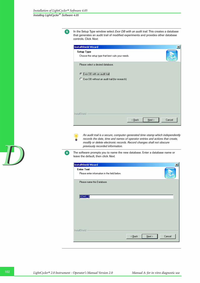
102
DD
Installation of LightCycler® Software 4.05
Installing LightCycler® Software 4.05
In the Setup Type window select Exor DB with an audit trail. This creates a database that generates an audit trail of modified experiments and provides other database controls. Click Next.
An audit trail is a secure, computer-generated time-stamp which independently records the date, time and names of operator entries and actions that create, modify or delete electronic records. Record changes shall not obscure previously recorded information.
The software prompts you to name the new database. Enter a database name or leave the default, then click Next.
�
�
LightCycler® 2.0 Instrument - Operator’s Manual Version 2.0 Manual A: for in vitro diagnostic use

DD
Installation of LightCycler® Software 4.05
Installing LightCycler® Software 4.05
If a database with the same name already exists, you are prompted to use the existing database or create a new database with the same name. Click Next.
Creating a new database with the same name overwrites the existing database.
Select the default settings to install the LightCycler® Software 4.05 or browse to select a location. Click Next.
�
�
103Software

104
DD
Installation of LightCycler® Software 4.05
Installing LightCycler® Software 4.05
The installation process installs the following icons on the desktop:
LightCycler® Software 4.05 icon , Exor 3 icon
Select the location for program icons. These are locations to start the LightCycler® Software 4.05 from. Deselect the icon locations you do not want, and then click Next.
When the InstallShield Wizard Complete window appears, the installation is complete. Click Finish. After a reboot of the computer you can launch the software by pressing the LightCycler® Software 4.05 icon.
�
LightCycler® 2.0 Instrument - Operator’s Manual Version 2.0 Manual A: for in vitro diagnostic use

DD
Installation of LightCycler® Software 4.05
Installing LightCycler® Software 4.05
5.3.1 Saving an existing database and installing additional databases
For backup purposes it is recommended to save a copy of your database routinely.Limited by the capacity of a CD it is recommended to save your database at a size ofmaximally 700 MB. To check the size of your database, proceed as follows:
To check the database size:
In case you need to compress the database file (e.g., if the database has exceeded the sizeof 700 MB), you can use the CompactIB tool.
To compress a database file:
To save the database on a CD follow the procedure described in Using the CD-RW Drive.
In the Windows Explorer select C:\Program Files\Roche\Exor3\Data (the path corre-sponds to the default setting during installation; it may vary depending on what you entered during installation of the database file. See also Installing LightCycler® Software 4.05, step 4).
Right-click on the database (*.IB) you want to check. From the menu select Properties; read the size from the corresponding menu item.
In the Start menu select Programs/Roche/CompactIB
The Compact Interbase Database File window opens. In the Database File to Compact box enter the directory of the database or click then navigate to a location, then click Open.
Click on Compact to start the process.
�
�
�
�
�
105Software

106
DD
Installation of LightCycler® Software 4.05
Installing LightCycler® Software 4.05
To install additional databases:
If the LightCycler® Software 4.05 is already installed on your computer, you can use the
LightCycler® Software 4.05 installation utility to install additional databases:
Insert the LightCycler® Software 4.05 CD. Double-click LightCycler_Software_405_Setup.exe, if installation doesn’t start automatically.
The Setup Type window is displayed. Leave the default setting Install a database file, and then click Next.
Select the default settings to install the database engine or browse to select a loca-tion. Click Next.
�
�
�
LightCycler® 2.0 Instrument - Operator’s Manual Version 2.0 Manual A: for in vitro diagnostic use

DD
Installation of LightCycler® Software 4.05
Installing LightCycler® Software 4.05
Select the default settings to install the database file or browse to select a location. Click Next.
In the Setup Type window select Exor DB with an audit trail. This creates a database that generates an audit trail of modified experiments and provides other database controls. Click Next.
An audit trail is a secure, computer-generated time-stamp which independently records the date, time and names of operator entries and actions that create, modify or delete electronic records. Record changes shall not obscure previously recorded information.
�
�
107Software

108
DD
Installation of LightCycler® Software 4.05
Installing LightCycler® Software 4.05
The software prompts you to name the new database. Enter a database name or leave the default, then click Next.
If a database with the same name already exists, you are prompted to use the existing database or create a new database with the same name. Click Next.
Creating a new database with the same name overwrites the existing database.
�
�
LightCycler® 2.0 Instrument - Operator’s Manual Version 2.0 Manual A: for in vitro diagnostic use

DD
Installation of LightCycler® Software 4.05
Installing LightCycler® Software 4.05
The software prompts you to enter a port number for the database. Leave the default value or enter a unique port number, then click Next.
Select the location for program icons. Deselect the icon locations you do not want, and then click Next.
�
109Software

110
DD
Installation of LightCycler® Software 4.05
Installing LightCycler® Software 4.05
The installation process installs another Exor3 icon on your desktop:
A message states that the maintenance is complete. Click Finish.�
LightCycler® 2.0 Instrument - Operator’s Manual Version 2.0 Manual A: for in vitro diagnostic use

DD
Installation of LightCycler® Software 4.05
Installing LightCycler® Software 4.05
5.3.2 Logging on to different databases
You can log on to an additionally installed database by selecting the database in the Log onto pull down menu.
To include an additionally installed database:
Double-click the LightCycler® Software 4.05 icon to launch the LightCycler® Software 4.05.
A login dialog box opens. Click on Options to display the list of known object servers.
Click on Add. An Objekt Server Properties window opens.
Enter a name for the database and its location. The location is always composed of the word “localhost” and the port number of the database to be integrated, divided by a colon. Click OK.
To figure out the port number for a database, point at the Exor3 icon in the system tray, and then read the object server’s properties from the display.
�
�
�
�
111Software

112
DD
Installation of LightCycler® Software 4.05
Installing LightCycler® Software 4.05
The database is included in the List of known Object Servers and can be selected in the Log on to box.
Select a database in the List of known Object Servers and click on Remove to remove it, or click on Edit to change the name or location of the database.
�
�
LightCycler® 2.0 Instrument - Operator’s Manual Version 2.0 Manual A: for in vitro diagnostic use

DD
Installation of LightCycler® Software 4.05
Removing LightCycler® Software 4.05
5.4. Removing LightCycler® Software 4.05
To uninstall LightCycler® Software 4.05:
Shutdown all running database engines by right-clicking the Exor3 icon in the system tray and selecting Shutdown.
Insert the LightCycler® Software 4.05 CD. Double-click LightCycler_Software_405_Setup.exe, if installation doesn’t start automatically. The Setup Type window is displayed. Select Uninstall LCS4.05 Software, and then click Next.
You are prompted to confirm the deletion. Click OK.
�
�
�
113Software

114
DD
Installation of LightCycler® Software 4.05
Removing LightCycler® Software 4.05
After the software has been removed, a message states that the maintenance is complete. Click Finish.
�
LightCycler® 2.0 Instrument - Operator’s Manual Version 2.0 Manual A: for in vitro diagnostic use

DD
Installation of LightCycler® Software 4.05
Changing the Default Administrator Password and Creating User Accounts
5.5 Changing the Default Administrator Password and Creating User Accounts
The LightCycler® Software 4.05 installation process creates a default user account withsystem administrator privileges. The user name is "admin" and the initial password is"LightCycler01". You will be prompted to change your initial password upon your firstlogin.
After installing the software you will also need to create user accounts, so others can usethe software. Each system (that is, each local computer) has its own set of user accounts.For each system you can create the following:
õ Local Administrator accounts that have the same privileges as the System Adminaccount. Each person with a Local Administrator account can create other useraccounts.
õ Expert User and Standard User accounts, which have fewer privileges than LocalAdministrator accounts. For information about user accounts and their associatedprivileges see chapter Managing User Access.
Before you begin determine the following:
õ The new password for the System Admin account you need to change.
õ The user names, login names, and passwords for the initial set of user accounts for thelocal computers.
115Software

116
DD
Installation of LightCycler® Software 4.05
Changing the Default Administrator Password and Creating User Accounts
To log on to a local computer:
On a LightCycler® computer double-click the LightCycler® Software 4.05 icon to launch the LightCycler® Software 4.05.
A login dialog box opens. Leave the default values for the user name admin and log on tolocation LocalExor3. Enter the password LightCycler01.
Upon your first login, you are prompted to change your password. Click OK. A Passworddialog box is displayed.
õ Enter the default password (LightCycler01) for the System Admin in the Password box.
õ Enter the new password in the New Password box and again in the Confirm Passwordbox. Click OK.
The password must contain at least six characters and contain one number and oneupper case character.
Passwords are case-sensitive. Remember the password or keep it in a safe place. Donot share your password with others.
Assure to be logged on to an Exor DB with an audit trail. If you are logged on to theExor DB with an audit trail, the word "Traceable" is displayed in the Statusbar.
LightCycler® 2.0 Instrument - Operator’s Manual Version 2.0 Manual A: for in vitro diagnostic use

DD
Installation of LightCycler® Software 4.05
Changing the Default Administrator Password and Creating User Accounts
To create user accounts:
To create new user accounts, from the Tools menu select Manage Users. The UserManagement tool opens. The Work with Users option is selected by default. To create anew user account, click New User. The View/Edit User dialog box opens.
In the first box, type the user’s full name. In the second box, type the user’s “user name” he wants to use as the login name.In the third box, type a password for the user.In the fourth box, retype the password.In the last box, select the user’s role. The available roles are:
Local Administrator: Creates an administrator account that gives the user completeaccess to the software. A Local Administrator can create and editother user accounts.
Expert User: Creates a general user account that gives the user extensive accessto the software. The Expert User cannot create and edit useraccounts.
Standard User: Creates a general user account that gives the user limited access tothe software.
For detailed information about the privileges associated with each role see chapterManaging User Access.
When finished click Done and repeat the procedure to create other user accounts, asneeded.
When finished, click Close to close the Manage Users window or Exit from the File menuto close the LightCycler® Software 4.05 application.
117Software

118
DD
Installation of LightCycler® Software 4.05
Connecting an Instrument
5.6 Connecting an Instrument
Before a LightCycler® Instrument can be used to run an experiment, the instrumentinformation must be added to the database. Adding the instrument to the database alsoadds the instrument name to the list of available instruments in the Run module. This istypically done by Roche, but it might be useful to understand the procedure.
A new instrument will be automatically detected and added to the database whenexecuting a Roche Macro. Automatic instrument detection does not require Expert Useror Local Administrator user privileges.
A user with Expert User or Local Administrator privileges can add an instrument to thedatabase manually or by having the software search for instruments.
One PC must not be used with 2 LightCycler® Instruments simultaneously.
5.6.1 Adding a New Instrument Automatically
You can add a new instrument to the database and to the list of available instruments byletting the software search for all instruments currently connected to the computer. Thisapproach is useful when you do not know the instrument’s COM port.
LightCycler® 2.0 Instrument - Operator’s Manual Version 2.0 Manual A: for in vitro diagnostic use

DD
Installation of LightCycler® Software 4.05
Connecting an Instrument
Adding a new instrument automatically by letting the software search
This procedure detects all instruments currently connected to the computer, includingthose that are already in the database.
Prerequisites:You must have Expert User or Local Administrator privileges.
To let the software detect a new instrument:
The new instrument is added to the LightCycler® Software 4.05 database, and its name isadded to the Instruments folder in the Navigator. The instrument name is now availablefrom the instrument list in the Run module, so the instrument can be selected forLightCycler® runs.
Make sure the instrument is physically connected to the computer and is powered on.
Turn on the computer, start the LightCycler® software, then log in. Be sure the instrument is powered on before you start the software.
Click Run in the toolbar or New Experiment on the Front window to open the Run module.
Click Options, then select Search for instruments. The Options button is located in the upper right corner of the Run window next to the instrument box.
The Discover Instruments dialog box opens.
If you know the instrument’s COM port, select Find on selected com port, then select the port from the pull-down list. If you do not know the port, select Auto – Detect and click Next.
When the software detects a new instrument that has no entry in the current LightCycler® Software 4.05 database, it prompts you to provide a name for the instrument. Enter a name, then click OK.If no instruments are found, the software displays “Unable to find any instruments”. Make sure the instruments are connected and powered on, then click Back to restart the search.
After instruments are found, the dialog box displays a list of all the instruments con-nected to the computer.
Select the new instrument you want to add to the database, then click Finish.
�
�
�
�
�
�
�
�
119Software

120
DD
Installation of LightCycler® Software 4.05
Connecting an Instrument
5.6.2 Adding a New Instrument Manually
Prerequisites:
You must have Expert User or Local Administrator privileges.
You must know which COM port the instrument is attached to.
To add a new instrument manually:
The software finds the instrument connected to the designated COM port and thenautomatically fills in the Instrument Id, Instrument Version, and Last ConnectedComputer boxes.
The instrument is added to the current LightCycler® Software 4.05 database, and itsname appears in the Instruments folder in the Navigator. The instrument name will nowbe available from the instrument pull-down list in the Run module, so the instrumentcan be selected for LightCycler® runs.
Make sure the instrument is physically connected to the computer and is powered on.
Turn on the computer, start the LightCycler® Software 4.05, then log in. Be sure the instrument is powered on before you start the software.
Click New or select New from the File menu.
Select LightCycler® Instrument, then click OK.
The New Instrument window opens. The instrument fields are at the top of the work pane.
In the Instrument Name box, type a name of your choice for the instrument.
In the I/O Port box, select the COM port the instrument is attached to and click Connect.
�
�
�
�
�
�
�
LightCycler® 2.0 Instrument - Operator’s Manual Version 2.0 Manual A: for in vitro diagnostic use

DD
Installation of LightCycler® Software 4.05
Connecting an Instrument
5.6.3 Removing an Instrument
If an instrument is no longer connected to the local computer, its name should beremoved from the list of instruments in the Run module. If the instrument is no longeravailable for use at all, it should also be removed from the LightCycler® Software 4.05database.
Prerequisites:You must have Local Administrator privileges to remove an instrument.
To remove an instrument from the instrument list:
To remove an instrument from the database:
To remove the instrument from the instrument list, select Manage Known Instruments from the Tools menu. The list of instruments is displayed.
Select the instrument you want to delete, then click Delete.
To remove the instrument from the current database, right-click the instrument name in the Navigator.
Click Delete.
You are prompted to confirm the deletion. Click Yes.
�
�
�
�
�
121Software

122
DD
LightCycler® 2.0 Instrument - Operator’s Manual Version 2.0 Manual A: for in vitro diagnostic use

Chapter E • Maintenance describes the maintenance procedures that are required for the LightCycler® 2.0 Instrument.
Maintenance

124
EE
LightCycler® 2.0 Instrument - Operator’s Manual Version 2.0 Manual A: for in vitro diagnostic use
1. General Maintenance ................................................................................................................................... 125
2. Cleaning Instructions ................................................................................................................................... 1252.1 General Cleaning ................................................................................................................................................ 1252.2 Preventive Maintenance................................................................................................................................... 1252.3 Removable Fan .................................................................................................................................................... 126
3. Change of O-Ring ........................................................................................................................................... 1283.1 Removal of the O-Ring..................................................................................................................................... 1283.2 Insertion of the O-Ring..................................................................................................................................... 129
4. Consumables and Spare Parts ................................................................................................................ 1304.1 Consumables........................................................................................................................................................ 1304.2 Spare Parts............................................................................................................................................................ 130
5. Disposal of Consumables and Reagents........................................................................................... 130
E Maintenance Page
Maintenance

EE
General Maintenance
Maintenance
1. General Maintenance
The LightCycler® 2.0 Instrument is maintenance-free.
2. Cleaning Instructions
Never clean the LightCycler® 2.0 Instrument without turning the instrumentpower switch off and disconnecting the power cable.
Do not poor fluids into the thermal chamber.
As with all potentially biohazardous specimens, universal safety precautions shallbe taken when handling and processing samples. Spills shall be immediately disin-fected with an appropriate disinfectant solution to avoid spreading contaminationto laboratory personnel or equipment.
Handling and disposal of infectious material shall be performed according to local safetyguidelines.
2.1 General Cleaning
Clean the housing of the LightCycler® 2.0 Instrument with a mild commercial detergent.If necessary use 70% Ethanol for disinfecting the instrument housing.
To clean the LightCycler® Centrifuge Adapters, remove them from the cooling blockbefore wiping them clean with a lab tissue soaked with decontamination solution. Usecommercialized reagents such as License to kill (Biodelta) or DNA Zap (Ambion). Do notautoclave the cooling block.
If capillary breakage occurs, perform the following steps, as appropriate:
� Clean the LightCycler® 2.0 Sample Carousel, by removing capillary fragments usingthe brushes provided with the LightCycler® 2.0 Instrument.
� Refer to Removable Fan for details on cleaning the thermal chamber.
Contact your local Roche representative if capillary breakage occured.
The LightCycler® Sample Carousel can be autoclaved. In case the LightCycler® SampleCarousel is autoclaved regularly it is recommended to change the O-Ring after 50autoclaving cycles.
2.2 Preventive Maintenance
The area around the instrument shall be checked regularly, to ensure that the air flowaround the LightCycler® 2.0 Instrument is unrestricted and that books, papers, or othersupplies are not interfering with the air flow.
125Maintenance

126
EE
Cleaning instructions
Removable Fan
2.3 Removable Fan
The fan is fixed in the thermal chamber with a knurled screw and can be releasedmanually as indicated in the pictures. This allows easy cleaning of the thermal chamber.
Switch off and unplug the LightCycler® 2.0 Instrument before removing the fan.
To release the fan turn the knurled screw to the left.�
LightCycler® 2.0 Instrument - Operator’s Manual Version 2.0 Manual A: for in vitro diagnostic use

127
EE
Cleaning instructions
Removable Fan
To clean the thermal chamber proceed as follows:
Only screw the fan into place, manually. Do not use any tools to screw the fan e.g.,an Allen key.
Do not poor fluids into the thermal chamber.
Make sure you don't touch or bend the thermal sensor in the chamber whencleaning it. In case the thermal sensor was bent by accident, this may cause faultytemperature measurements or even cause the capillaries to crash during a run. Incase of doubt call your Roche representative.
Take out the fan.
Clean the chamber with a soft lint-free cloth. For cleaning purposes use 70% Mikrozid (Schülke & Mayr GmbH, Norderstedt, Germany) or 1:3 Clorox Regular (The Clorox Company, Oakland, USA) or 3% Kohrsolin (Bode Chemie GmbH, Hamburg, Germany) or 70% Ethanol according to manufacturers’ instructions.
Clean the optical window with an optical polishing cloth.
Make sure that no liquid is left in the chamber before re-inserting of the fan.
Insert the fan and fix it by following the steps, described to release it, in reverse order.
�
�
�
�
�
Maintenance

128
EE
Change of O-Ring
Removal of the O-Ring
3. Change of O-Ring
3.1 Removal of the O-Ring
To remove the O-Ring, use a suitable tool (e.g., a blunt pair of tweezers or a small screwdriver as indicated in the picture), place it carefully under the O-Ring and raise it. The preferred position for doing this is one of the capillary cavities.
Remove the O-Ring completely from the carousel.
�
�
LightCycler® 2.0 Instrument - Operator’s Manual Version 2.0 Manual A: for in vitro diagnostic use

EE
Change of O-Ring
Insertion of the O-Ring
3.2 Insertion of the O-Ring
Put the new O-Ring on the carousel and press it down with your thumbs into the “furrow“. Always press opposite points.
Turn the carousel and proceed as described in step 1.
Proceed as described in steps 1 and 2 until the O-Ring fits in the „furrow“.
Finally smooth out the O-Ring over the whole carousel with your fingers.
�
�
�
�
129Maintenance

130
EE
Consumables and spare parts
Consumables
4. Consumables and Spare Parts
The consumables and spare parts that are needed to operate the LightCycler® 2.0Instrument are listed below. These materials may be obtained by contacting your RocheDiagnostics representative.
4.1 Consumables
LightCycler® Capillaries (20 µl), Cat.No.: 11 909 339 001
LightCycler® Capillaries (100 µl), Cat.No.: 03 337 090 001
4.2 Spare Parts
LightCycler® 2.0 Sample Carousel (20 µl) marked with a brown tag, Cat.No.: 03 603 962 001LightCycler® 2.0 Sample Carousel (100 µl) marked with a purple tag, Cat.No.: 03 603 954 001LightCycler® Centrifuge Adapters, Cat.No.: 11 909 312 001LightCycler® Capillary Releaser, Cat.No.: 03 603 920 001LightCycler® Capping Tool, Cat.No.: 03 357 317 001LightCycler® Sample Carousel O-Ring, Cat.No.: 03 603 989 001
A printer and a barcode reader are provided locally upon request.
5. Disposal of Consumables and Reagents
� Discard the capillaries into a solid waste box after use.
� Discard reagents and waste material according to local safety guidelines.
� Contact your local Roche Diagnostics representative for disposal of the instrument orinstrument parts.
LightCycler® 2.0 Instrument - Operator’s Manual Version 2.0 Manual A: for in vitro diagnostic use

Chapter F • Troubleshooting lists all LightCycler® system messages, explains their meaning and indicates appropriate measures.
Troubleshooting

132
FFLightCycler® 2.0 Instrument - Operator’s Manual Version 2.0 Manual A: for in vitro diagnostic use
1. Instrument Errors ............................................................................................................................................ 133
2. Instrument-Related Errors ......................................................................................................................... 138
3. Algorithm Errors and Messages ............................................................................................................. 142
4. Miscellaneous messages ........................................................................................................................... 144
5. Index....................................................................................................................................................................... 145
F Troubleshooting Page
Troubleshooting

133
FF
Instrument Errors
TroubleshootingThe monitoring of an experiment and the error history records are used to support theservicing of the LightCycler® 2.0 Instrument. The LightCycler® Software Version 4.05offers the tools to collect all parameters related to the runs performed. Refer to Chapter DSoftware for more details on generating error log files.
System messages which may potentially occur are listed below. For each message theprobable cause and corrective action typically required for solving the problem areshown. Call your Roche representative for troubleshooting assistance.
Data derived from a run where a system message appeared should be consideredcritically. It is recommended to repeat the run where the validity of the results isdoubtful.
1. Instrument Errors
Error Code
System message Possible Cause Corrective Action
20 Temperature min error Hardware problem concerning temperature control
Reboot system, call Roche Service if error persists
21 Temperature max error Hardware problem concerning temperature control
Reboot system, call Roche Service if error persists
22 Temperature ADC timeout Hardware problem concerning temperature control.
Call Roche Service
25 Cabinet fan will not switch off Hardware error Call Roche Service
26 Overheat from hardware sensor Hardware problem concerning temperature control
Call Roche Service
27 Min fan error Hardware error Call Roche Service
28 Max fan error Hardware error Call Roche Service
29 Blue LED error Hardware error Call Roche Service
30 Fluorescence channel 1 min error Hardware error Call Roche Service
31 Fluorescence channel 1 max error Hardware error Call Roche Service
32 Fluorescence channel 2 min error Hardware error Call Roche Service
32 Fluorescence channel 2 max error Hardware error Call Roche Service
34 Fluorescence channel 3 min error Hardware error Call Roche Service
35 Fluorescence channel 3 max error Hardware error Call Roche Service
36 Rotor home position error Hardware error Call Roche Service
37 Photometer home position error Hardware error Call Roche Service
38 Photometer lost steps Hardware error Call Roche Service
39 Rotor lost steps Hardware error Reboot system, call Roche Service if error persists
40 Gain adjust error Hardware error Call Roche Service
41 Carousel setting out of scope Hardware error Call Roche Service
42 Carousel calculation out of scope Hardware error Call Roche Service
45 Parameter version mismatch Hardware error Call Roche Service
Troubleshooting

134
FF
Instrument Errors
49 Checksum error Temperature module error Call Roche Service
50 EEPROM write error Hardware module error Reboot system, call Roche Service if error persists
51 EEPROM read error Hardware module error Reboot system, call Roche Service if error persists
52 EEPROM busy error Hardware module error Reboot system, call Roche Service if error persists
53 EEPROM page error Hardware module error Reboot system, call Roche Service if error persists
54 Internal bitbus error Hardware module error Reboot system, call Roche Service if error persists
55 Transmit buffer LC -> PC overflow Communication error Close all programs running simultaneously to the LightCycler® software on the PC. If error still occurs, call Roche Service
56 Receive buffer LC <- PC overflow Communication error Reboot system, call Roche Service if error persists
57 Internal order buffer overflow Communication error Call Roche Service
58 Protocol address <> 'S’wrong processor address, software or PIC error
Communication error Call Roche Service
59 Mathematics error for BASE-210 Communication error Call Roche Service
60 Protocol data or order from PC not valid data exceed limits or unknown order, software error
Communication error Call Roche Service
61 Protocol number of data not valid Communication error Call Roche Service
62 Internal protocol order not validunknown order, firmware error
Communication error Call Roche Service
70 Timeout transmit data to photometer
Photometer communication error
Reboot system, call Roche Service if error persists
71 Timeout receive data from photometer
Photometer communication error
Reboot system, call Roche Service if error persists
72 Timeout photometer measurement Photometer error Reboot system, call Roche Service if error persists
73 Checksum error in binary answer Photometer error Reboot system, call Roche Service if error persists
74 Timeout UART busy Photometer error Reboot system, call Roche Service if error persists
75 Error from photometer message register
Photometer error Call Roche Service
80 Photometer bit 00: watch dog reset Photometer error Reboot system, call Roche Service if error persists
81 Photometer bit 01: brown out reset Photometer error Reboot system, call Roche Service if error persists
Error Code
System message Possible Cause Corrective Action
LightCycler® 2.0 Instrument - Operator’s Manual Version 2.0 Manual A: for in vitro diagnostic use

FF
Instrument Errors
82 Photometer bit 02: communication error
Photometer error Reboot system, call Roche Service if error persists
84 Photometer bit 04: ADC hardware error
Photometer error Reboot system, call Roche Service if error persists
85 Photometer bit 05: LED hardware error
Photometer error Reboot system, call Roche Service if error persists
86 Photometer bit 06: checksum error EEPROM
Photometer error Reboot system, call Roche Service if error persists
87 Photometer bit 07: service mode enabled
Photometer error Reboot system, call Roche Service if error persists
88 Photometer bit 08: write protection disabled
Photometer error Reboot system, call Roche Service if error persists
89 Photometer bit 09: power supply error
Photometer error Reboot system, call Roche Service if error persists
90 Photometer bit 10: self test active
Photometer error Reboot system, call Roche Service if error persists
91 Photometer bit 11: not ready for commands
Photometer error Reboot system, call Roche Service if error persists
92 Photometer bit 12: calculation error
Photometer error Reboot system, call Roche Service if error persists
93 Photometer bit 13: checksum error Flash
Photometer error Reboot system, call Roche Service if error persists
100 Fluorescence [1..12]=0 Min error Fluorescence signal error Reboot system, call Roche Service if error persists
101 Fluorescence 1 Max error Fluorescence signal error Check dye concentration, call Roche Service if error persists
102 Fluorescence 2 Max error Fluorescence signal error Check dye concentration, call Roche Service if error persists
103 Fluorescence 3 Max error Fluorescence signal error Check dye concentration, call Roche Service if error persists
104 Fluorescence 4 Max error Fluorescence signal error Check dye concentration, call Roche Service if error persists
105 Fluorescence 5 Max error Fluorescence signal error Check dye concentration, call Roche Service if error persists
106 Fluorescence 6 Max error Fluorescence signal error Check dye concentration, call Roche Service if error persists
107 Fluorescence 7 Max error Fluorescence signal error Check dye concentration, call Roche Service if error persists
108 Fluorescence 8 Max error Fluorescence signal error Check dye concentration, call Roche Service if error persists
109 Fluorescence 9 Max error Fluorescence signal error Check dye concentration, call Roche Service if error persists
110 Fluorescence 10 Max error Fluorescence signal error Check dye concentration, call Roche Service if error persists
Error Code
System message Possible Cause Corrective Action
135Troubleshooting

136
FF
Instrument Errors
111 Fluorescence 11 Max error Fluorescence signal error Check dye concentration, call Roche Service if error persists
112 Fluorescence 12 Max error Fluorescence signal error Check dye concentration, call Roche Service if error persists
127 Error in temp processor Error from TEMP processor Call Roche Service
148 Temperature min error Hardware problem concerning temperature control
Reboot system, call Roche Service if error persists
149 Temperature max error Hardware problem concerning temperature control
Reboot system, call Roche Service if error persists
150 Temperature heat up error Hardware problem concerning temperature control
Call Roche Service
151 Temperature cool down error Hardware problem concerning temperature control
Call Roche Service
152 Temperature heat up timeout Hardware problem concerning temperature control
Call Roche Service
153 Temperature cool down timeout Hardware problem concerning temperature control
Reboot system, call Roche Service if error persists
154 Overheat from hardware sensor Hardware problem concerning temperature control
Call Roche Service
155 Temperature ADC timeout Hardware problem concerning temperature control
Reboot system, call Roche Service if error persists
157 Fan Brake error Fan error Call Roche Service
158 Min fan error Hardware problem concerning temperature control
Call Roche Service
159 Max fan error Fan error Call Roche Service
160 Fan alarm from hardware sensor Fan error Check if the fan is inserted cor-rectly. If error occurs with cor-rectly installed fan, call Roche Service
163 Lid unlock error Lid lock error Lid can be opened manually in urgent cases, refer to Chapter Operation. Call Roche Service
164 Lid lock error Lid lock error Reboot system, call Roche Service if error persists
173 Parameter version mismatch Reboot system, call Roche Service if error persists
174 Checksum error on Main board EEPROM
Reboot system, call Roche Service if error persists
175 EEPOT invalid Temperature module error Reboot system, call Roche Service if error persists
176 Serial number T-Module invalid Temperature module error Reboot system, call Roche Service if error persists
177 Checksum error on T-Module EEPROM
Temperature module error Call Roche Service
Error Code
System message Possible Cause Corrective Action
LightCycler® 2.0 Instrument - Operator’s Manual Version 2.0 Manual A: for in vitro diagnostic use

FF
Instrument Errors
178 EEPROM write error Hardware module error Reboot system, call Roche Service if error persists
179 EEPROM read error Hardware module error Reboot system, call Roche Service if error persists
180 EEPROM busy error Hardware module error Reboot system, call Roche Service if error persists
181 EEPROM page error Hardware module error Reboot system, call Roche Service if error persists
182 Internal Bit-Bus Error Hardware module error Reboot system, call Roche Service if error persists
183 Transmit buffer LC -> PC overflow Communication error Close all programs running simultaneously to the LightCycler® software on the PC. If error still occurs, call Roche Service
184 Receive buffer LC <- PC overflow Communication error Call Roche Service
185 Internal order buffer overflow Communication error Call Roche Service
186 Protocol address <> 'T' Communication error Call Roche Service
187 Mathematics error for BASE-210 Communication error Call Roche Service
188 Protocol data or order from PC not valid
Communication error Call Roche Service
189 Protocol number of data not valid Communication error Call Roche Service
190 Internal protocol order not valid Communication error Call Roche Service
255 Error in step processor Error from STEP processor Call Roche Service
Error Code
System message Possible Cause Corrective Action
137Troubleshooting

138
FF
Instrument-Related Errors
2. Instrument-Related Errors
Instrument-related errors may occur during running an experiment, running the RealTime Fluorimeter or during operating the instrument screen of the software. In this list[...] is meant as a placeholder in certain error messages and may stand for an instrumentname, a serial number etc.
Error Message Possible Cause Corrective Action
Are you sure the computer is connected to a LightCycler® instrument?
Communication error Restart instrument and software.
Attempted to call the DetectOnPort method on a connected instrument [...] whose port [...] is different than the port to be used in the detection [...]!
Wrong port used Check port connection.
Attempted to connect object [...] to a different instrument [...] on port [...]. Please choose the correct instrument object in the software, connect to a different instrument/port, or create a new instrument object if this is a new instrument (hasn't been connected before)!
Other instrument connected to port than expected
Choose the correct instrument object in the software and connect the adequate instrument. Create a new instrument object if you want to connect a new instrument that has not been connected before.
Can only disconnect the instrument while it's not running!
User tried to disconnect an instrument in the instrument screen while it was running a selftest, run, etc.
Wait until current process is finished.
Cannot close window while [...] is running!
User tried to close the instru-ment screen while the instru-ment is running
Finish the run or abort it.
Can't apply templates to runs that have been started.
Handling error Finish or abort current run.Apply new template to new run.
Can't change the I/O port while the instrument is connected!
User tried to change the I/O port in the instrument screen while connection was already established
Press ‘Connect’ button again to disconnect the instrument and to end communication.
Can't initialize the LightCycler® instrument. No I/O port has been assigned!
No I/O port chosen in the instrument screen.
Check I/O port chosen in the instrument screen.
Can't start the Run until the instrument lid is closed!
Handling error Close the lid before starting a run.
Can't start the self-test until the instrument lid is closed!
Handling error Close the lid before starting to operate the instrument.
Communication Error: Unable to load firmware!
Communication error Restart instrument and software.
Disconnecting the instrument will terminate RTF. Are you sure you want to disconnect the instrument?
Depress ‘Connect’ in instru-ment screen while running RTF
Stop RTF first.
LightCycler® 2.0 Instrument - Operator’s Manual Version 2.0 Manual A: for in vitro diagnostic use

FF
Instrument-Related Errors
Error reading firmware version. Error code = […], Data = [...]!
Communication error Restart instrument and software.
Information* Program 0, Segment 0: 30 is an invalid temperature target.
User imported a Nucleic Acid experiment containing a segment with 30°C as the temp target.
Correct the experiment settings.
Instrument [...] already exists. User tried to create two instrument objects for the same instrument
Leave 2nd instrument object without saving. Select already existing instrument object for instrument.
Instrument [...] was detected. Do you want to start the run with this instrument?
User clicked “Start Run” on Run window when no instrument was connected
Answer the question. If it is the wrong instrument select an other instrument.
Instrument is already running! Handling error Finish or abort current run, start new run thereafter.
Internal Error: [...]. Firmware component was unable to return the firmware data!
Corrupted firmware in the firmware component.
Restart instrument and software. Call Roche Service if error persists.
Internal Error: [...]. Firmware property was unassigned!
Developer Error: The firmware component was not setup properly.
Restart instrument and software. Call Roche Service if error persists.
LightCycler® Error: [...] Instrument error code Restart instrument and software. Call Roche Service if error persists.
Please close the instrument lid before performing a self test.
Handling error Close the instrument lid before starting a run.
Please close the instrument lid before starting a run
Handling error Close the instrument lid before starting a run.
Please close the instrument lid before starting RTF.
Handling error Close the lid before operating the instrument.
Port [...] is currently unavailable (possibly in use by another instrument or process). Details: [...]
Port already in use by another instrument or software.
Use other port. Wait until process is finalized. Close other software.
Real time fluorimeter aborted with an error
Instrument error Check error log
Real time fluorimeter communication timed out! Please verify the instrument is properly connected.
Communication error Check cable
Received a protocol with an error while performing a Step self test! Please verify the instrument is properly connected.
Communication error Check cable
Received an error protocol while seeking samples! Please verify the instrument is properly connected.
Communication error Check cable. Restart instrument and software.
Error Message Possible Cause Corrective Action
139Troubleshooting

140
FF
Instrument-Related Errors
Received fatal error during run! Instrument error Check error log.
Run timed out after not receiving any data from the instrument!
Communication error Check cable
Step self test timed out! Please verify the instrument is properly connected.
Communication error Check cable
The firmware crc value is declared incorrectly!
Hardware error Call Roche Service
The following samples were not found during the seek process. Do you want to continue the run?
Missing samples or missing fluorescent dye.
Check if all sample capillaries were inserted correctly. Check if fluorescent dye has been added. Confirm the message to continue the run or abort it by pressing “No”.
The instrument firmware failed to load. Please verify that the instrument is properly connected.
Communication error Check cable, restart instrument and software.
The instrument is already running another experiment!
Handling error Finish or abort current run before starting a new run.
The instrument is currently busy run-ning Real Time Fluorimeter.
Handling error Finish current process and restart action.
The instrument timed out while seeking samples! Please verify the instrument is properly connected.
Communication error Check cable
The instrument timed out while waiting for sample search protocol! Please verify the instrument is properly connected.
Communication error Check cable. Restart instrument and software.
The instrument’s lid was opened during the run!
Handling error Repeat experiment.
The instrument's lid has been opened during the run. The run will now be terminated.
Handling error Repeat run.
The instruments lid was opened during real time fluorimeter!
Handling error Do not open the lid when operating the instrument.
The run aborted with an error.The instrument timed out while waiting for sample search protocol!Please verify the instrument is properly connected.
Communication error Check cable. Restart instrument and software.
The run aborted with an error. Invalid checksum on returned protocol.
Communication error Check cable. Restart instrument and software. Call Roche Service if error persists.
The seek process found the following samples which were not supposed to contain any data (their positions were initially flagged as empty): [...]!
Mismatch between SAM file and seek
Check loading; restart experiment.
Error Message Possible Cause Corrective Action
LightCycler® 2.0 Instrument - Operator’s Manual Version 2.0 Manual A: for in vitro diagnostic use

FF
Instrument-Related Errors
The selected instrument is of a different type ([…] Channel) than the instrument specified in the experi-ment ([…] Channel). Continuing could lead to a loss of data (e.g. loss of channel information in the sample editor). Do you want to continue?
Instrument is of different type (3 channel versus 6 channel) than selected in experiment
Chose correct instrument type for experiment or use other experiment.
The stored object reports the instrument subclass to be of type [...], but the instrument "says" the type is [...]!
Wrong instrument type con-nected.
Choose the correct instrument object in the software and connect the adequate instrument. Create a new instrument object if you want to connect a new instrument that has not been connected before.
Timed out while waiting for instrument to adjust temperature! Please verify the instrument is properly connected.
Communication error Check cable
Unable to backup run data! Disk full; no access rights Assure that the disk used has enough memory space and check the user rights.
Unable to communicate with the instrument. Please verify the instrument is properly connected.
Communication error Check cable. Restart instrument and software.
Unable to find [...] on port [...]. Do you want to search for the instrument on other ports?
Instrument not connected to the specified port.
Choose the correct instrument object in the software and connect the adequate instrument. Create a new instrument object if you want to connect a new instrument that has not been connected before.
Unable to start self test with instrument [...].Please make sure the instrument is properly connected.
Communication error Check cable
Error Message Possible Cause Corrective Action
141Troubleshooting
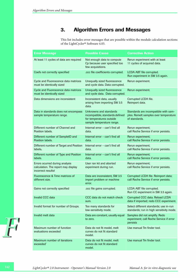
142
FF
Algorithm Errors and Messages
3. Algorithm Errors and Messages
This list includes error messages that are possible within the module calculation sectionsof the LightCycler® Software 4.05.
Error Message Possible Cause Corrective Action
At least 11 cycles of data are required Not enough data to compute Cp because user specified too few acquisitions.
Rerun experiment with at least 11 cycles of acquired data.
Coefs not correctly specified .ccc file coefficients corrupted. LCDA ABT file corrupted.Run experiment in SW 3.5 again.
Cycle and Fluorescence data matrices must be identically sized
Unequally sized fluorescence and cycle data. Data corrupted.
Rerun experiment.
Cycle and Fluorescence data matrices must be identically sized
Unequally sized fluorescence and cycle data. Data corrupted.
Rerun experiment.
Data dimensions are inconsistent Inconsistent data, usually arising from importing SW 3.5 data.
Corrupted LCDA file. Reimport data.
Data in standards does not encompass sample temperature range.
Unknowns and standards incompatible, standards defined for temperatures outside sample temperature range.
Standards are incompatible with sam-ples. Remelt samples over temperature of standards.
Different number of Channel and Position labels.
Internal error – can’t find all data.
Rerun experiment; call Roche Service if error persists.
Different number of SampleID and Position labels.
Internal error – can’t find all data.
Rerun experiment; call Roche Service if error persists.
Different number of Target and Position labels.
Internal error – can’t find all data.
Rerun experiment; call Roche Service if error persists.
Different number of Type and Position labels.
Internal error – can’t find all data.
Rerun experiment; call Roche Service if error persists.
Errors ocurred during analysis calculation. The report may display incorrect results!
User ran kit and aborted experiment during run.
Rerun experiment; call Roche Service if error persists.
Fluorescence & Time matrices of different size.
Data are inconsistent, SW 3.5 import problem or machine error.
Corrupted LCDA file. Reimport data; call Roche Service if error persists.
Gains not correctly specified .ccc file gains corrupted. LCDA ABT file corrupted.Run CC experiment in SW 3.5 again.
Invalid CCC data CCC data do not match check sum.
Corrupted CCC data. Reload LCDA data if imported; redo CCC experiment.
Invalid format for number of Groups. Too many standards for low-sensitivity mode.
Select different standards; use in-run standards; run in high sensitivity mode.
Invalid melt data Data are constant, usually equal to zero.
Samples did not amplify. Redo experiment; call Roche Service if error persists
Maximum number of function evaluations exceeded
Data do not fit model, melt curves do not fit standard model.
Use manual Tm finder tool.
Maximum number of iterations exceeded'
Data do not fit model, melt curves do not fit standard model.
Use manual Tm finder tool.
LightCycler® 2.0 Instrument - Operator’s Manual Version 2.0 Manual A: for in vitro diagnostic use

FF
Algorithm Errors and Messages
More measurements needed Not enough data gathered in experiment.
Make sure run has acquisitions specified; decrease temperature ramp rate.
Negative Concentration not allowed User specifies negative conc. values.
Reset Cp limits in sample editor.
Negative CPRange limits not allowed User specifies negative Cp values.
Reset Cp limits in sample editor.
Negative Fluorescences not allowed Negative values of fluorescence observed
Rerun experiment; call Roche Service if error persists.
No fluorescence data Missing fluorescence information in raw data.
Make sure run has acquisitions specified.
Not enough data to color compensate CCC experiment doesn’t have enough data to compute compensation.
Rerun CC experiment, and gather enough data.
Qualitative Detection: Exception ECrossingPoint raised with message “At least 11 cycles of data are required.”
Program did not have the necessary number of cycles for the analysis. Program may be inaccurate, or user may have aborted run before cycles complete.
Rerun experiment with at least 11 cycles of acquired data.
Resolution cutoff must be nonnegative and less than Score threshold
Invalid user input of resolution. Decrease Resolution threshold below Score threshold.
Standard curve could not be calculated Not enough standard data points.
Increase number or samples in experiment.
Temperature & Time matrices of different size.
Data are inconsistent, SW 3.5 import problem or machine error.
Corrupted LCDA file. Reimport data; call Roche Service if error persists.
Too much missing data, cycle numbers must be contiguous
Missing acquisitions in cycling.Machine didn’t collect data.Data corrupted.
Rerun experiment; call Roche Service if error persists.
Unable to compute standard curve Not enough standards for linear regression, regression requires 3 or more standards.
Increase the number of standards in experiment.
Upper limit of ConcRange greater than lower limit
User specifies incorrect conc. limits.
Reset concentration limits in sample editor.
Upper limit of CPRange greater than lower limit
User specifies incorrect Cp limits.
Reset Cp limits in sample editor.
[…] not a valid correction factor. Non-positive correction factor. Reset correction factor on paring tab.
[…] not a valid multiplication factor Non-positive multiplication factor.
Reset multiplication factor on paring tab.
Error Message Possible Cause Corrective Action
143Troubleshooting

144
FF
Miscellaneous messages
4. Miscellaneous messages
This section lists messages for modules and features not covered above.
Error Message Possible Cause Corrective Action
An error occurred while importing file […].FLO. Please verify that all ATF files exist and are valid.: ABT file not found.
User selected a .flo file to import that did not have a corresponding .abt file.
Check if the corresponding experiment data files are complete
Archive log entry was empty!! User imported a file and saved it, then highlighted file in the Navigator and checked File > Revisions. Message appears when there are no previous revisions in the Revisions pane.
Cannot stop Exor. There is <n> user connected.
The user tried to shut down Exor while one or more users were logged in.
Wait until all users are logged out
Please export modified objects before logging out or closing LCS4.
There was a failure in communication with Exor. The object cannot be saved in the database, but the user can export the object and reimport it when communication is reestablished.
Export the modified objects and reimport them after restart of the LightCycler® Software
The file does not have a checksum and will not be imported. Checksum failure!.
User tried to import an LightCycler® Software 4.0 .ixo file into LightCycler® Software 4.05
LightCycler® 2.0 Instrument - Operator’s Manual Version 2.0 Manual A: for in vitro diagnostic use
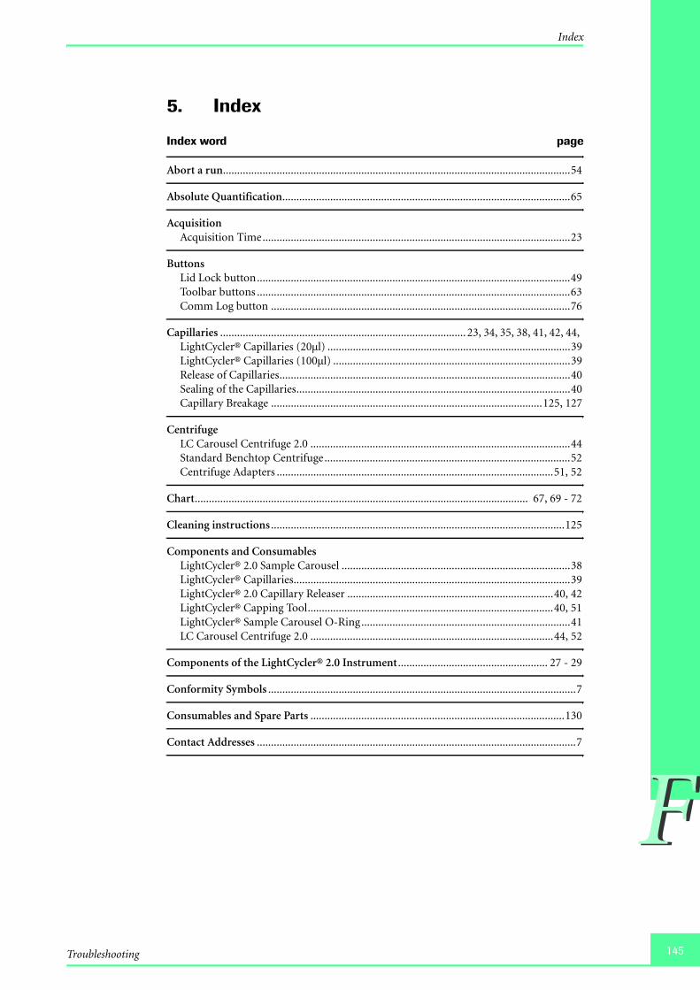
FF
Index
5. Index
Index word page
Abort a run...........................................................................................................................54
Absolute Quantification......................................................................................................65
AcquisitionAcquisition Time.............................................................................................................23
ButtonsLid Lock button...............................................................................................................49Toolbar buttons ...............................................................................................................63Comm Log button ..........................................................................................................76
Capillaries ....................................................................................... 23, 34, 35, 38, 41, 42, 44, LightCycler® Capillaries (20µl) ......................................................................................39LightCycler® Capillaries (100µl) ....................................................................................39Release of Capillaries.......................................................................................................40Sealing of the Capillaries.................................................................................................40Capillary Breakage ................................................................................................125, 127
CentrifugeLC Carousel Centrifuge 2.0 ............................................................................................44Standard Benchtop Centrifuge.......................................................................................52Centrifuge Adapters ..................................................................................................51, 52
Chart...................................................................................................................... 67, 69 - 72
Cleaning instructions ........................................................................................................125
Components and ConsumablesLightCycler® 2.0 Sample Carousel .................................................................................38LightCycler® Capillaries..................................................................................................39LightCycler® 2.0 Capillary Releaser .........................................................................40, 42LightCycler® Capping Tool.......................................................................................40, 51LightCycler® Sample Carousel O-Ring..........................................................................41LC Carousel Centrifuge 2.0 ......................................................................................44, 52
Components of the LightCycler® 2.0 Instrument ..................................................... 27 - 29
Conformity Symbols .............................................................................................................7
Consumables and Spare Parts ..........................................................................................130
Contact Addresses .................................................................................................................7
145Troubleshooting

146
FF
Index
Index word page
ConventionsText Conventions............................................................................................................ 14Symbols........................................................................................................................... 14
Cooling block ...................................................................................................................... 51
Data Station .................................................................................................................. 22, 33Installation of the Computer ......................................................................................... 33CD-RW drive .................................................................................................................. 33
Database ...............................................................................................57, 61, 67, 73, 88, 118Updating the database.................................................................................................... 74
DetectionSpecifications for the Detection System........................................................................ 23Detection Channels ........................................................................................................ 37
Disposal of consumables and reagents............................................................................ 130
EmissionHeat Emission................................................................................................................. 21Blue LED emission ......................................................................................................... 36Emission wavelengths of fluorophores.......................................................................... 37
Error CodesInstrument errors ................................................................................................ 133 - 137Instrument-related errors ................................................................................... 138 - 141Algorithm errors and messages .......................................................................... 142 - 143Miscellaneous messages ............................................................................................... 144Viewing application errors............................................................................................. 76
Error log ....................................................................................................................... 75 - 75
Excitation .................................................................................................................23, 36, 37
Exit Software ..........................................................................................................59, 62, 117
Fan ................................................................................................................................. 34, 35Removable Fan .................................................................................................... 126 - 127
LightCycler® 2.0 Instrument - Operator’s Manual Version 2.0 Manual A: for in vitro diagnostic use

FF
Index
Index word page
FRET (fluorescence energy transfer) ................................................................................37,
Infectious Material ................................................................................................14, 16, 125
InstallationInstallation of the LightCycler® 2.0 Instrument.................................................... 31 - 32Space and Power Requirements......................................................................................30Environmental Requirements.........................................................................................31Storage Conditions..........................................................................................................31Safety Lock.......................................................................................................................32Computer Installation.....................................................................................................33Software Installation ............................................................................................. 99 - 120
InstrumentConnecting and Removing Instruments............................................................ 118 - 121Instrument logs ...............................................................................................................75
Intended Use ..........................................................................................................................8
LEDBlue LED..............................................................................................................23, 36, 37Status LED .......................................................................................................................48
License Disclaimer......................................................................................................... 9 - 12
Lid Lock..........................................................................................................................48, 49
LightCycler® Instrument 2.0Warranty............................................................................................................................8Intended Use......................................................................................................................8Specifications........................................................................................................... 21 - 23Temperature Kinetics ......................................................................................................24Components of the LightCycler® 2.0 Instrument ................................................. 27 - 29Installation............................................................................................................... 30 - 32Start up the data station..................................................................................................33System description .................................................................................................. 34 - 37Operation ................................................................................................................ 47 - 54Maintenance ..................................................................................................................125Troubleshooting .................................................................................................. 133 - 149
Macros ..................................................................................................................................58
Maintenance ......................................................................................................................125General Maintenance ....................................................................................................125Preventive Maintenance................................................................................................125General Cleaning...........................................................................................................125Removable Fan .................................................................................................... 126 - 127Change of O-Ring ............................................................................................... 128 - 129Disposal of consumables and reagents.........................................................................130
147Troubleshooting

148
FF
Index
Index word page
ObjectsOpening Objects............................................................................................................. 66Creating Objects ............................................................................................................. 66Saving Objects ................................................................................................................ 66Renaming Objects .......................................................................................................... 66Deleting Objects ............................................................................................................. 66Exporting Objects........................................................................................................... 66Importing Objects .......................................................................................................... 66
Operation ..................................................................................................................... 47 - 54Start-Up .......................................................................................................................... 47Status LED ...................................................................................................................... 48Lid Lock .......................................................................................................................... 49Preparing a LightCycler® Run ................................................................................ 50 - 53Abort a Run ................................................................................................................... 54, Shut-Down ..................................................................................................................... 54Operation log.................................................................................................................. 75
O-Ring ................................................................................................................ 41, 128 - 129Removal of the O-Ring ................................................................................................ 128Insertion of the O-Ring................................................................................................ 129
Password .............................................................................................................................. 98
Photometer............................................................................................................. 34, 36 - 37Schematic of the Photometer Unit ................................................................................ 36Detection Channels ........................................................................................................ 37
Power Supply................................................................................................................. 21, 30
Queries ................................................................................................................................ 73
RangeDate Range...................................................................................................................... 73
Report ........................................................................................................................... 67 - 68
Revisions ....................................................................................................................... 62, 80
Revision History ................................................................................................................... 7
RunPreparing a run........................................................................................................ 50 - 53Abort a run ............................................................................................................... 54, 80Run module ........................................................................................................58, 63, 65,
Shut-down ........................................................................................................................... 54
System Data Query Object................................................................................................. 76
LightCycler® 2.0 Instrument - Operator’s Manual Version 2.0 Manual A: for in vitro diagnostic use
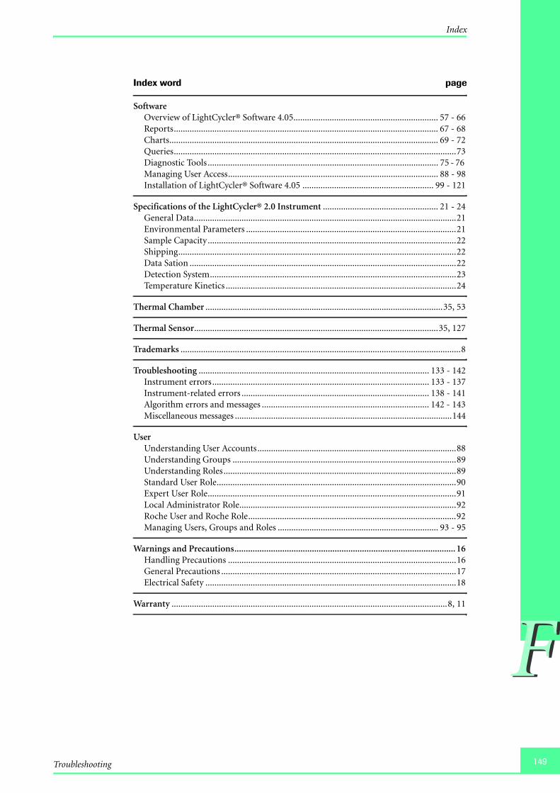
FF
Index
Index word page
SoftwareOverview of LightCycler® Software 4.05................................................................ 57 - 66Reports..................................................................................................................... 67 - 68Charts....................................................................................................................... 69 - 72Queries.............................................................................................................................73Diagnostic Tools ...................................................................................................... 75 - 76 Managing User Access............................................................................................. 88 - 98Installation of LightCycler® Software 4.05 .......................................................... 99 - 121
Specifications of the LightCycler® 2.0 Instrument ................................................... 21 - 24General Data....................................................................................................................21Environmental Parameters .............................................................................................21Sample Capacity..............................................................................................................22Shipping...........................................................................................................................22Data Sation ......................................................................................................................22Detection System.............................................................................................................23Temperature Kinetics ......................................................................................................24
Thermal Chamber .........................................................................................................35, 53
Thermal Sensor............................................................................................................35, 127
Trademarks ............................................................................................................................8
Troubleshooting ...................................................................................................... 133 - 142Instrument errors................................................................................................ 133 - 137Instrument-related errors ................................................................................... 138 - 141Algorithm errors and messages .......................................................................... 142 - 143Miscellaneous messages ................................................................................................144
UserUnderstanding User Accounts........................................................................................88Understanding Groups ...................................................................................................89Understanding Roles.......................................................................................................89Standard User Role..........................................................................................................90Expert User Role..............................................................................................................91Local Administrator Role................................................................................................92Roche User and Roche Role............................................................................................92Managing Users, Groups and Roles ....................................................................... 93 - 95
Warnings and Precautions................................................................................................. 16Handling Precautions .....................................................................................................16General Precautions ........................................................................................................17Electrical Safety ...............................................................................................................18
Warranty ..........................................................................................................................8, 11
149Troubleshooting

150
FF
LightCycler® 2.0 Instrument - Operator’s Manual Version 2.0 Manual A: for in vitro diagnostic use

Inspiring Discovery
Diagnostics
Roche Diagnostics GmbHRoche Applied Science68298 MannheimGermany
www.roche-applied-science.com1204
-046
2449
1001