Embed Size (px)
Citation preview

1.
2.
4.
5.
3.
6.
CONTROLS / COMPONENTS1. LED Display2. Output Setting Knob3. Ramp Time Setting Knob4. Manual Activation
Lever5. Mounting Bracket 6. Harness Connector
MOUNTINGNote: Read all instructions thoroughly before beginning.The Journey HD electric brake control can be mounted in a variety ofpositions, making it easily and comfortably accessible from the dri-ver’s position of most any tow vehicle. The unit is designed to bemounted horizontally or vertically, at any angle above or below thedash (fig. 1, 2 & 3)
1. Determine an appropriatemounting location that is easilyaccessible from a comfortable seateddriving position. Note: The brake control unitmust be securely mounted to asolid surface (i.e. onto orbeneath the vehicles dash)within easy reach of the driver.2. Place the mounting bracket into the desired position on the vehi-
cle and mark the location of the bracket mounting slots.
HD electric brake control. Lesser gauge wire may result in less thandesirable braking operation. Minimum wire gauges are as follows:
• 1 - 2 Axle Trailers: 12 Gauge Wire Minimum• 3 - 4 Axle Trailers: 10 Gauge Wire Minimum
Soldered connections are favorable when wiring the Journey HD elec-tric brake control, however crimp-style connectors are acceptable inmaking these connections.
Caution: Improper connection of a trailer break-away kitmay cause damage to the trailer brake system and/or thebrake control.
FOR TOW VEHICLES EQUIPPED WITH ORIGINAL EQUIPMENT FACTORY TRAILER TOW PACKAGES:Ensure the tow vehicles brake control power circuit (+) is capable ofdelivering the required amount of current needed for the trailers brak-ing system (Refer to the tow vehicle and trailer owners manuals). Ifthe brake control power circuit (+) does not meet the demand, wiredirectly to the battery (steps 1 - 7 following).
Note: As vehicle wiring differs by manufacturer, use of a pre-wiredbrake control harness is recommended. Valley offers a wide range ofcustom harnesses designed to mate directly between the tow vehicle’sfactory brake control plug and the Journey HD’s connector.
Caution: As wire colors differ by manufacturer, the vehicleharness wire colors may differ from those on the brakecontrol pigtail. Refer to the following chart, the tow vehi-cle’s owners manual and the instructions supplied with theoriginal equipment factory connector for correct brake con-trol wiring instructions.
Congratulations on your pur-chase of the Journey HDTM trail-er brake control module. Solid
state dependability and polarity protection are just a few features theJourney HD offers that are not found on many other brake controls.
FEATURES• The Journey HD provides an easy to read digital display whichcommunicates a full range of diagnostic information and allows forprecise brake output adjustment.
• The Journey HD Electric Brake Control is polarity protected. If thepositive (+) and negative (-) power leads are reversed, the unit iso-lates itself from the power input and protects itself from damage.
• Easy Precise Setup - Separate thumb wheel controls for outputpower and ramp (reaction) time provide full setup adjustability.
• Stop Lamp Activation - When applying the trailer brakes by utiliz-ing the manual slider alone, the Journey HD will supply power tothe trailer’s brake lights.
• Mounts Anywhere - Leveling of the Journey HD Electric BrakeControl is not required. This electronic unit is designed to operatein a wide range of positions.
• The Journey HD Electric Brake Control supports 1 to 4 axle trail-ers (2 to 8 brakes) and is ideal for use on trailers with electronicallyactivated hydraulic braking systems.
• Full Power Manual Over Ride - The Journey HD’s ManualActivation Lever provides Full Available Power to the trailer brakeswhen applied.
3. Using a 1⁄8” drill bit, drill the holes marked in step 2 into themounting surface. Caution: Ensure that the area directly behind the mountingsurface is clear of obstructions that may be damaged whiledrilling.4. Using a screwdriver or
1⁄4” nut driver, secure thebracket to the vehicle withthe two 1⁄4” self tappingscrews (provided). Takecare not to strip the holesby over-tightening thescrews.5. Mount the Journey HD
electric brake control into the bracket using two 1⁄4” self tappingscrews (provided) (fig. 4).Caution: Do not use longer screws than those provided.
WIRINGNote: Read all instructions thoroughly before beginning.The use of proper gauge wire is critical when installing the Journey
fig. 1
Above Dash Mounting
WIRING (Continued)FOR TOW VEHICLES NOT EQUIPPED WITH ORIGINAL
EQUIPMENT FACTORY TRAILER TOW PACKAGES:The brake control must be spliced into the vehicle’s exist-ing wiring harness as follows:1. Mount a 30 amp automotive style circuit breaker near the tow
vehicle’s positive (+) battery terminal. Using a length of 10 ga.stranded wire, strip 5⁄16” of insulation from one end and attach a 3⁄8” 12 ga. crimp-style ring terminal. Strip 5⁄16” from the opposite end andattach a #10 12 ga. crimp style ring terminal. Connect this lead to thecircuit breaker terminal labeled “BATT”. The opposite end will mountto the vehicle’s positive (+) battery terminal during step 12.Caution: Do not attach to the vehicle’s positive (+) batteryterminal at this time.2. Feed a length of 10 ga. stranded duplex wire (white & black)
from the brake control to the vehicles battery compartment. Caution: When passing wire through sheet metal, alwaysutilize an existing grommet, add a grommet or use siliconerubber to insulate the wire from the hole.
3. Attach a 3⁄8” 12 ga. ring terminal to the White wire, and a #10 12 ga. ring terminal to the Black wire in the same manner as step 2. 4. Attach the Black wire to the circuit breaker terminal labeled “AUX”.
Caution: Do not connect the circuit breaker to the vehiclebattery at this time.5. Attach the White wire to the vehicles Negative (-) battery post.
Note: If the brake control is not properly grounded or is notreceiving a proper power supply, it may operate intermit-tently or not at all. Ensure that the White wire is securelyconnected to the Negative (-) battery terminal.6. From the driver’s area, attach the brake control’s Black “BATT”
wire to the opposite end of the Black wire attached to the “AUX” sideof the circuit breaker using a yellow 10/12 ga. butt connector or bysoldering the leads together.7. Attach the brake controls White “GND (-)” wire to the opposite
end of the White wire leading to the vehicles negative (-) battery ter-minal using a yellow 10/12 ga. butt connector or by soldering theleads together.8A.For 1989-1991 Ford E & F-Series Trucks & Vans
with anti-lock brakes: (All other vehicles continue to Step 8B)Locate the crescent shaped turn signal harness connector (fig. 5)located on the steering column under the dash. The connector willhave two rows of wires. A row of four wiresand a row of seven wires. Attach the brakecontrols Red “STLT” wire to the light greenwire (second in the row of seven) with a 14ga. wire tap.Caution: Do not connect to the Red wire with the GreenStripe as serious damage may occur.
+-
BATT (BLACK)GND (WHITE)
STLT (RED)BRAKES (BLUE)
12 V
OLT
TOW
VEH
ICLE
BAT
TERY
BATT
AUXWIRE TAP
BRAKE PEDAL SWITCHCONNECT TO COLD (SWITCHED) SIDE
(ONLY ON WHEN PEDAL IS DEPRESSED)
30 AMP 12vAUTO-RESET
CIRCUIT BREAKER
CAUTION: DISCONNECT TOW VEHICLES NEGATIVE (-) BATTERY CABLE PRIOR TO WIRING BRAKE CONTROL
TRAILER CONNECTOR10 GA.
WIRE
WARNING: READ AND OBEYALL WARNINGS AND CAUTIONSPRINTED ON TOW VEHICLE BATTERY
10 GA.WIRE
LIGHT GREEN WIRE
SPLICE THE RED STOP LIGHT WIRE FROM THE BRAKE CONTROL TO THE LIGHT GREEN WIRE ON THE TURN SIGNAL HARNESS (ILLUSTRATED ABOVE) USING A WIRE TAP (PROVIDED).
NOTE: FOR 1989 - 1991 FORD F & E-SERIES TRUCKS AND VANS WITH ANTI-LOCK BRAKES:DO NOT CONNECT TO BRAKE PEDAL SWITCH.
TURN SIGNAL HARNESS CONNECTORLOCATED UNDER THE VEHICLE DASHNEAR THE STEERING COLUMN
JOURNEY HDBRAKE
CONTROL
+-
LIGHT GREEN WIRE
fig. 5
fig. 4
Factory Pigtail Brake Control Wire Color Wire Color Function
Red Connect To Black 12 Volt Positive (+)Light Blue Connect To Red Stop LightBlack Connect To White Ground (-)Dark Blue Connect To Blue Trailer BrakesBrown Not Used
White with Red Stripe Connect To Black 12 Volt Positive (+)Blue with White Stripe Connect To Red Stop LightGreen with Black Stripe Connect To White Ground (-)Blue Connect To Blue Trailer Brakes
Red with Black Stripe Connect To Black 12 Volt Positive (+)White with Tan Stripe Connect To Red Stop LightBlack Connect To White Ground (-)Blue Connect To Blue Trailer Brakes
Red Connect To Black 12 Volt Positive (+)Light Green Connect To Red Stop LightWhite Connect To White Ground (-)Dark Blue Connect To Blue Trailer BrakesBrown Not Used
Pink Connect To Black 12 Volt Positive (+)Red Connect To Red Stop LightWhite Connect To White Ground (-)Blue Connect To Blue Trailer BrakesBrown Not Used
Black with Green Stripe Connect To Black 12 Volt Positive (+)Green Not UsedGreen with White Stripe Connect To Red Stop LightBrown Connect To White Ground (-)Red Connect To Blue Trailer Brakes
ORIGINAL EQUIPMENT FACTORY BRAKE CONTROL CONNECTOR PIGTAIL
Select the connector that matches your factory supplied brake control connector pigtail
8B.For All Other Vehicles: Locate the stop light switch on the back side of the vehicles brakepedal. Determine which side of the switch is the “cold” or switchedside by probing the terminals of the switch with a test light or currentmeter. The cold terminal will only indicate power when the brakepedal is depressed. Connect the brake controls Red “STLT” wire tothe cold side of the stop light switch with a 14 ga. wire tap.9. Feed a length of 10 ga. Blue stranded wire from the brake con-
trol to the trailer connector at the rear of the vehicle. Caution: When passing wire through sheet metal, alwaysutilize an existing grommet, add a grommet or use siliconerubber to insulate the wire from the hole.10.Attach the brake controls Blue “BRAKE” wire to the Blue 10
Ga. wire using a 10/12 ga. butt connector.11.At the rear of the vehicle, attach the Blue wire to the vehicle’s
trailer connector brake terminal (see the connector’s wiring diagramfor the correct terminal location). 12.Connect the wire from the “BATT” side of the circuit breaker to
the vehicle’s positive (+) battery terminal.Note: The Black “Battery” wire must be connected directlyto the tow vehicle’s positive (+) battery terminal via a self-resetting 30 amp circuit breaker. Do not attempt to connectthis wire to the vehicle’s fuse panel or other accessorywiring. Failure to connect directly to the vehicle batterymay damage vehicle wiring and cause trailer brake failure.
CHEVROLET
DODGE
DODGE (Optional)
FORD
FORD (Optional)
TOYOTA
fig. 2
Below Dash Mounting
fig. 3
Below Dash Mounting
LED DISPLAYOnce the wiring is complete, the LED display will indicate one the fol-lowing, illustrating the brake controls activity:
• Power Conservation Mode - No Activity for 31⁄2 Hrs. or Longer. The Journey HD will Become Instantly Active when the Brake Pedal is Depressed.
• No Trailer Connected - Journey HD is Receiving Power and is Active.
• Trailer is Connected - Journey HD is Receiving Power and is Active.
• Manual Lever Applied - No Trailer Connected(Applies to Manual Lever Only)
• Manual Activation Lever or Vehicle Brakes Applied - Trailer is Connected (Output Reading is Based on Output Intensity Setting and Position of Manual Lever, if Applied)
TROUBLESHOOTINGIn addition to indicating output power and Load Range settings, theJourney HD is capable of communicating operating errors via its LEDdisplay.
• Trailer brake circuit may be lost or intermittent. Check the trailer connector for a secure dry connection.Note: It is normal for the Journey HD Brake Control to flash OC for a few moments after the circuit is disconnected.
• Short Circuit Situation - The trailer brake circuit may be shorted to ground. Check for improper wiring. The unit will reset once the situation is corrected.
• Charging System Error - There may be a charging system problem or an inadequate connection to the tow vehicle’s battery. The unit will reset once the situation is corrected.
OUTPUT & RAMP TIME SETTINGSPrior to towing, the Output Power must be adjusted for the individualtrailer being towed.1. Connect the desired trailer to the tow vehicle.2. Start the tow vehicle to ensure sufficient battery power is being
supplied to the brake control. While parked, depress the brake pedaland rotate the Output Setting Knob located on the left side of the con-trol until the LED display indicates 30.3. Continue to press on the brake pedal and rotate the Ramp Time
Setting Knob located on the right side of the control until the LEDdisplay reads -5.4. In an open and controlled area, release the brake pedal and drive
forward on a dry level surface at approximately 20 mph. Ensure thatample distance is available for safe braking and slowly apply thebrake control’s Manual Activation Lever until the trailer brakes fullyengage to stop the trailer. Note the output reading on the LED display.Caution: Full activation of the manual lever will apply100% Power to the trailer brakes.5. Release the Manual Activation Lever and rotate the Output Setting
Knob until the LED displays the same reading as that noted in step 4.6. Once again drive forward at approximately 20 mph. Ensure that
NOTE: In certain situations trailer brakes may not be capable of lock-ing up. This situation can be associated with brake wear, overall trail-er weight, trailer length and/or wire gauge. If the trailer brakes will notlock up during the setup procedures, it is recommended that all com-ponents of the braking system are checked to ensure safe towing. Caution: On some vehicles, manual operation of trailer brakes willnot override the tow vehicle’s cruise control operation.
OPERATING TIPS• Light pressure on the brake pedal will activate the trailer brakeswithout applying the tow vehicle brakes. This is useful when travers-ing grades, anticipating stops or correcting trailer sway.• Periodic adjustment of the Ramp Time and Output Setting Knobs
may be necessary to compensate for trailer loading, brake wear andvarying road conditions.• Application of the trailer brakes by utilizing either the brake pedal
or Manual Activation Lever will illuminate the trailer’s brake lights.• On some vehicles, the use of hazard flashers may pulse the trailer
brakes. To reduce this effect, adjust the Ramp Time to a lower setting,or install a pulse preventer.
BENCH TESTINGThe Journey HD can be field tested should correct operation be suspect.Remove the unit from the tow vehicle and wire to a 12 volt automotivebattery and #1156 automotive bulb as illustrated in figure 6.
Wiring1. Attach the unit’s Blue wire to one side of a standard #1156 12
volt automotive bulb by using a socket or by soldering the wire to thebulb.
TO
(Flashing)
0C0 5 99
0C
ample distance is available for safe braking and apply the brakepedal. If Trailer Brakes Lock Up:Reduce power to the trailer brakes by rotating the Output SettingKnob counter-clockwise. Reduced power is indicated by a decreasingreadout (smaller number) on the LED display.If Trailer Braking was Insufficient:Increase power to the trailer brakes by rotating the Output SettingKnob clockwise. Increased power is indicated by an increasing read-out (larger number) on the LED display.7. Continue to repeat steps 5 and 6 until the desired power output
has been achieved. The brake control output should be just below thepoint where the trailer wheels lock up, yet there is sufficient force toallow for maximum brake force.8. Once the initial output power level has been established, adjust
the Ramp Time by performing additional low speed stops (20 mph)utilizing the tow vehicles brake pedal to ensure smooth combinationbraking between the tow vehicle and the trailer.
If Trailer Brakes are Lagging the Vehicle:Rotate the Ramp Time Setting Knob clockwise to increase the speedof trailer brake application.
If Trailer Brakes are Overly Aggressive:Rotate the Ramp Time Setting Knob counter-clockwise to decreasethe rate of trailer brake application.9. Once the desired Ramp Time has been established, it may be
necessary to re-adjust the Power Output Setting (steps 4-5).
Caution: Increasing the power output setting or ramp timesetting should NOT be utilized as an option to adjusting orrepairing trailer brakes.
SC
C S(Blank)
5. Attach the Red wire to the Positive (+) battery terminal. The unit’sLED display will indicate an output reading beginning at 05 andslowly increase to 99. The light bulb illumination should increase inintensity in conjunction with the LED reading. 6. Slowly rotate the Output Adjustment Knob counterclockwise
toward the front. the LED display should smoothly decrease from 99to 05. Note: The lightbulb intensity should decrease in conjunctionwith the LED display.7. Rotate the Output Setting Knob to the rear of the control so that
the display reads 99 and rotate the Ramp Time Setting Knob clock-wise to the front of the control. the LED display should change modeto indicate ramp time, moving from -0 to -9 as the thumbwheel isrotated. 8. Disconnect and reconnect the red wire from the battery’s positive
(+) terminal. The light bulb should light brightly with a minimal delay.9. If the Journey HD brake control does not function as described in
the steps above, return the unit to an authorized distributor for serviceor replacement.
SERVICE & SUPPORT• For questions regarding installation and usage, call (800) 344-3230.
2. Attach a length of 16 ga. or larger wire to the other side of the #1156 bulb. 3. Attach the White wire to the Negative (-) battery terminal.4. Attach the Black wire to the Positive (+) battery terminal.
Note: Do not attach the unit’s Red wire or the bulb to the battery atthis time. Caution: Do NOT touch the brake control’s REDwire to Ground (-) as this will destroy the unit.Testing1. Rotate the Output Setting Knob clockwise and the Ramp Time
Setting Knob counter-clockwise (each toward the rear of the unit.2. Move the Manual Activation Lever to the left. The unit’s LED dis-
play should temporarily indicate .9 (-.9).3. Connect the light bulb to the Negative (-) battery terminal as
illustrated in fig. 6. Move the Manual Activation Lever to the left. TheLED display should increase from approximately 05 to 99 and thelight bulb illumination should increase in intensity in conjunctionwith the LED reading.4. Release the Manual Activation Lever. The LED display should
now display only decimal points (. .).
52740-998 rev B - 11/10/06
Tools Required:• Drill with 1/8” Bit• 1/4” Nut Driver• Phillips Screwdriver• Wiring Connector
Crimping Tool• Wire Cutter/Stripper• End Wrenches• Probe Style Test Light
Additional Material Required:•37194 Valley Brake Control Wiring Kit
or • 30’ 12 Ga. (or Heavier) Wire • 30 Amp 12v Auto-Reset
Circuit Breaker• 10/12 Ga. #10 Ring Terminal• 10/12 Ga. 3⁄8” Ring Terminal• 10/12 Ga. Butt Connectors• 14/16 Ga. Wire Tap• 4” Cable Ties
® 52740
© 2004-2006 Valley Industries
INSTALLATION INSTRUCTIONS
+-
BATT (BLACK)GND (WHITE)
12 V
OLT
TOW
VEH
ICLE
BAT
TERY
WARNING: READ AND OBEYALL WARNINGS AND CAUTIONSPRINTED ON TOW VEHICLE BATTERY
BRAKES (BLUE)STLT (RED)
ONLY CONNECT BULB TO NEGATIVE (-) TERMINAL AS NEEDED
STANDARD 12V #1156AUTOMOTIVE BULB(USE SOCKET OR SOLDERWIRES TO BULB)
DO NOT CONNECT RED WIRETO POSITIVE (+) TERMINALUNTIL STEP 5.
JOURNEY HDBRAKE
CONTROL
fig. 6
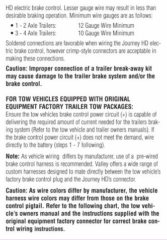
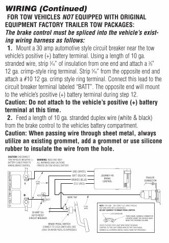
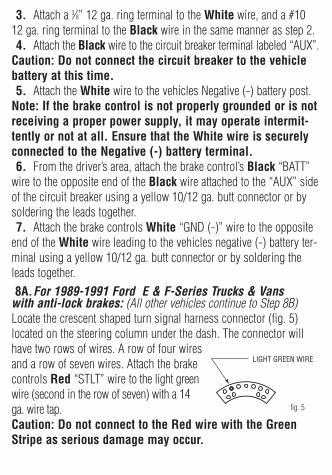