Embed Size (px)
Citation preview
1
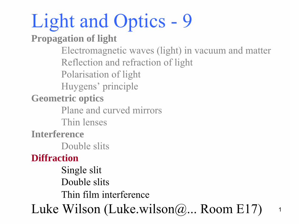
Light and Optics - 9Propagation of light
Electromagnetic waves (light) in vacuum and matterReflection and refraction of lightPolarisation of lightHuygens’ principle
Geometric opticsPlane and curved mirrorsThin lenses
InterferenceDouble slits
DiffractionSingle slitDouble slitsThin film interference
Luke Wilson (Luke.wilson@... Room E17)

2
• Single slit intensity distribution
• Double slit intensity distribution
• Thin film interference
http://science.sbcc.edu/physics/flash/optics/doubleslitphasors.html
3
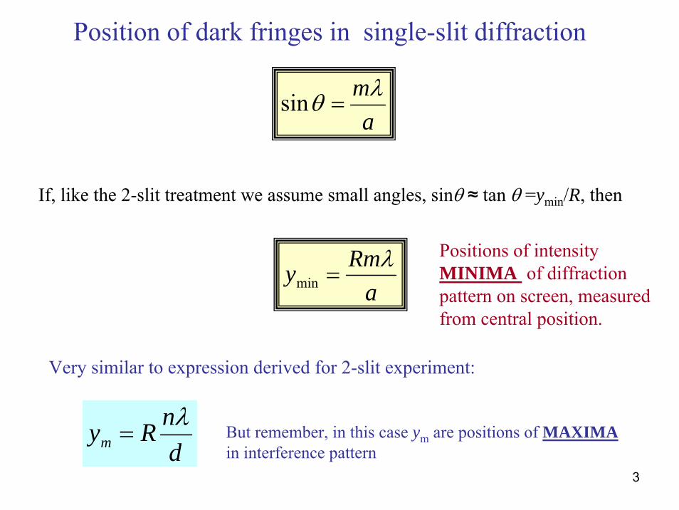
Position of dark fringes in single-slit diffraction
amλθ =sin
If, like the 2-slit treatment we assume small angles, sinθ ≈ tan θ =ymin/R, then
aRmy λ
=min
Positions of intensity MINIMA of diffraction pattern on screen, measured from central position.
Very similar to expression derived for 2-slit experiment:
dnRymλ
= But remember, in this case ym are positions of MAXIMAin interference pattern
4
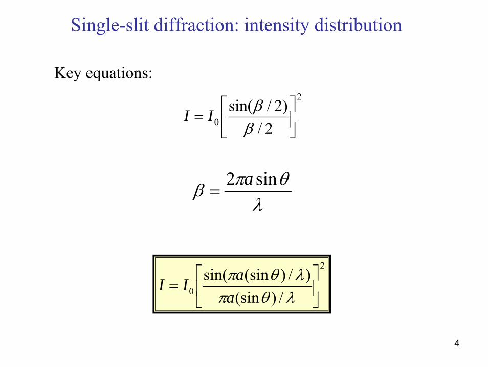
Single-slit diffraction: intensity distribution
2
0 2/)2/sin(⎥⎦
⎤⎢⎣
⎡=
ββII
λθπβ sin2 a
=
2
0 /)(sin)/)(sinsin(⎥⎦
⎤⎢⎣
⎡=
λθπλθπ
aaII
Key equations:

5
⎟⎠⎞
⎜⎝⎛′=
λπRdyIITOT
20 cos
“real” intensity distribution for double slits
The distribution derived earlier is for the idealised case of infinitely narrowslits:
’

6
“real” intensity distribution for double slits
If we allow the slits (spacing d) to have finite width a, then the TOTAL intensity distribution is given by the 2-slit intensity distribution
⎟⎠⎞
⎜⎝⎛=
2cos4 2
0φII
‘modulated’ by the intensity distribution for a single slit of width a:
2
/)(sin)/)(sinsin( ⎥⎦
⎤⎢⎣
⎡λθπλθπα
aaI

7
“real” intensity distribution for double slits
22
0 2/)2/sin(
2cos4 ⎥
⎦
⎤⎢⎣
⎡⎟⎠⎞
⎜⎝⎛=
ββφII
λθπβ sin2 a
=λ
θπφ sin2 d=

8
“real” intensity distribution for double slits
“ideal” pattern
Single slit pattern
“real” pattern
9
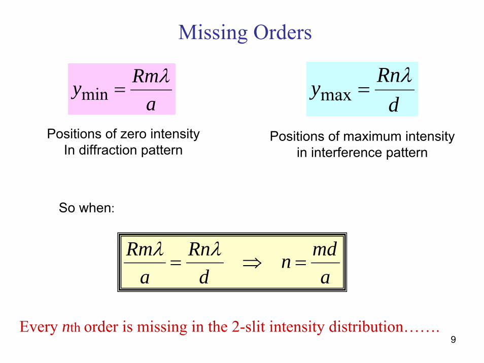
Missing Orders
aRmy λ
=min dRny λ
=max
Positions of zero intensityIn diffraction pattern
Positions of maximum intensityin interference pattern
amdn
dRn
aRm
=⇒= λλ
So when:
Every nth order is missing in the 2-slit intensity distribution…….
10
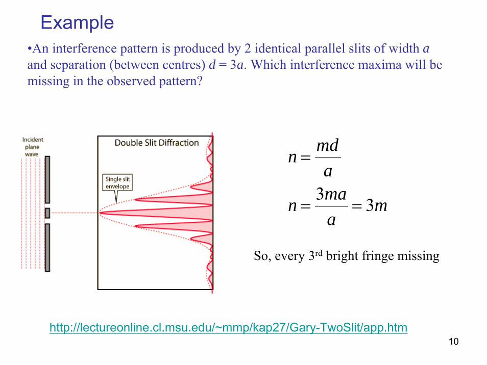
Example•An interference pattern is produced by 2 identical parallel slits of width aand separation (between centres) d = 3a. Which interference maxima will be missing in the observed pattern?
maman
amdn
33==
=
So, every 3rd bright fringe missing
http://lectureonline.cl.msu.edu/~mmp/kap27/Gary-TwoSlit/app.htm

11
Thin film interference
Light waves reflected from front and back surfaces of thin films can constructively or destructively interfere

12
Thin film interference – phase shift upon reflection
na > nb no phase shift na < nb π phase shift
13
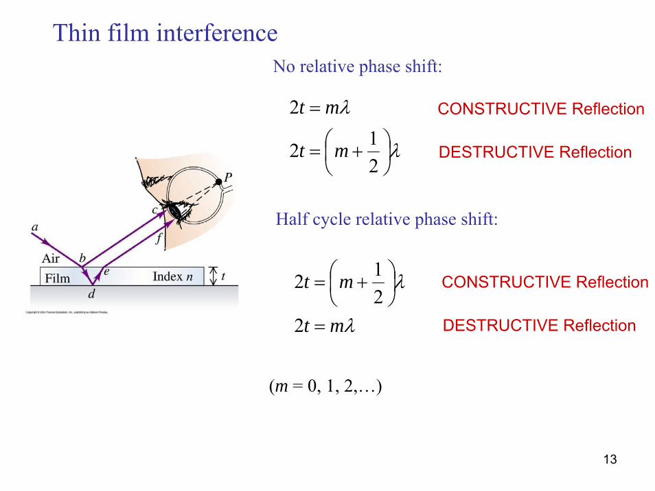
No relative phase shift:
Half cycle relative phase shift:
λ
λ
⎟⎠⎞
⎜⎝⎛ +=
=
212
2
mt
mt
(m = 0, 1, 2,…)
λ
λ
mt
mt
=
⎟⎠⎞
⎜⎝⎛ +=
2212
CONSTRUCTIVE Reflection
DESTRUCTIVE Reflection
CONSTRUCTIVE Reflection
DESTRUCTIVE Reflection
Thin film interference
14
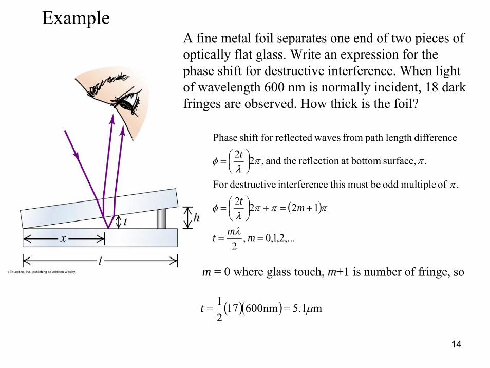
ExampleA fine metal foil separates one end of two pieces of optically flat glass. Write an expression for the phase shift for destructive interference. When light of wavelength 600 nm is normally incident, 18 dark fringes are observed. How thick is the foil?
( )
,...2,1,0 ,2
1222. of multiple odd bemust thisceinterferen edestructivFor
. surface, bottomat reflection theand ,22differencelength path fromwavesreflectedfor shift Phase
==
+=+⎟⎠⎞
⎜⎝⎛=
⎟⎠⎞
⎜⎝⎛=
mmt
mt
t
λ
πππλ
φ
π
ππλ
φ
m = 0 where glass touch, m+1 is number of fringe, so
( )( ) m1.5nm6001721 μ==t

15
Thin film interference – AR coatings
Film is about ¼ wavelength thick
Light undergoes a phase shift at both reflecting surfaces
The two reflected waves emerge from the film about ½ cycle out of phase
nglass > nfilm > nair

16
Summary
22
0 2/)2/sin(
2cos ⎥
⎦
⎤⎢⎣
⎡⎟⎠⎞
⎜⎝⎛=
ββφII
amdn
dRn
aRm
=⇒= λλ
Half cycle relative phase shift:
(m = 0, 1, 2,…)
λ
λ
mt
mt
=
⎟⎠⎞
⎜⎝⎛ +=
2212 CONSTRUCTIVE Reflection
DESTRUCTIVE Reflection
Double slits with finite slit width
Intensity distribution Missing orders
Thin film interference