Embed Size (px)
Citation preview
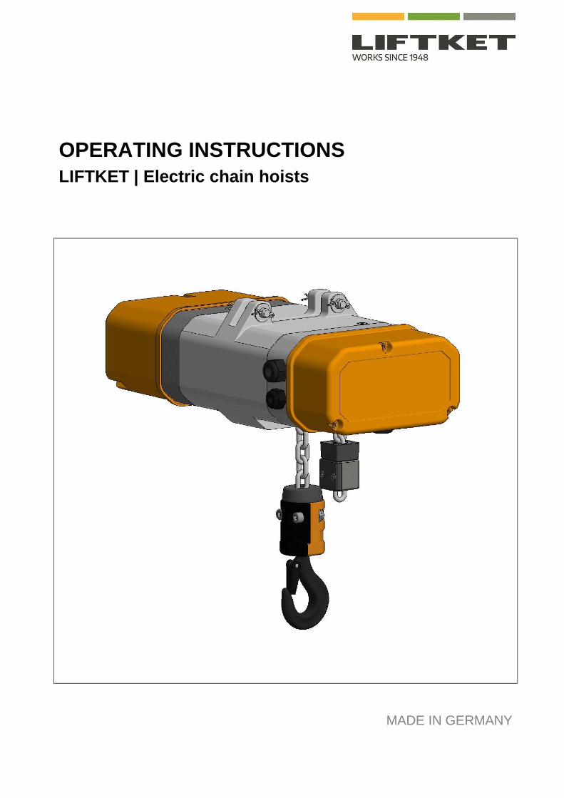
OPERATING INSTRUCTIONS
LIFTKET | Electric chain hoists
MADE IN GERMANY
2
Please do not use the electric chain hoist before all operators have carefully read and understood this manual and
signed the form on the rear cover.
LIFTKET Hoffmann GmbH
Dresdener Straße 64-68
04808 Wurzen / Germany
+49-3425-89 24-0
+49-3425-89 24-99
www.liftket.de
Ho 09/2019 englisch
Original operating instructions
© 2019
3
Contents
1 Safety advice .......................................................................................................................................................... 5 1.1 Advice for the use of electric chain hoists .............................................................................................................. 5 1.2 European regulations ............................................................................................................................................. 5 1.3 Spare parts ............................................................................................................................................................. 7
2 Technical overview ................................................................................................................................................. 7 2.1 Assembly possibilities ............................................................................................................................................ 7 2.2 Explanation of type designation.............................................................................................................................. 7 2.3 Sectional view ........................................................................................................................................................ 8 2.4 Schematic sketch of the load chain configuration ................................................................................................... 9
3 Assembly ................................................................................................................................................................ 9 3.1 Mechanical assembly ............................................................................................................................................. 9 3.1.1 Hook tackle............................................................................................................................................................. 9 3.1.2 Hook block............................................................................................................................................................ 10 3.1.3 Stationary suspended hoists – basic version ....................................................................................................... 11 3.1.3.1 Suspension with suspension eye ......................................................................................................................... 11 3.1.3.2 Suspension with single hole suspension eye ....................................................................................................... 11 3.1.3.3 Suspension with hook suspension ....................................................................................................................... 12 3.1.4 Gear ventilation .................................................................................................................................................... 13 3.1.5 Chain box ............................................................................................................................................................. 13 3.1.5.1 Mounting of the chain box .................................................................................................................................... 13 3.1.5.2 Oversize chain box ............................................................................................................................................... 14 3.1.6 Fitting the load chain in case of delivery without preassembled piece of load chain - single fall version .............. 14 3.1.7 Fitting the load chain in case of delivery with preassembled piece of load chain - single fall version ................... 15 3.1.8 Fitting the load chain - double fall version ............................................................................................................ 15 3.1.9 Replacing the load chain and hold down .............................................................................................................. 16 3.1.10 Electric chain hoists for inverted use .................................................................................................................... 16 3.2 Electric connections ............................................................................................................................................. 17 3.2.1 Mains connection ................................................................................................................................................. 17 3.2.1.1 Direct control ........................................................................................................................................................ 18 3.2.1.2 Low voltage control .............................................................................................................................................. 18 3.2.2 230 V single phase current 50 Hz ........................................................................................................................ 18 3.2.3 Electric limit switch for lift limitation ...................................................................................................................... 18 3.2.4 Voltages ............................................................................................................................................................... 19
4 Electric chain hoist with trolley .............................................................................................................................. 19 4.1 Mechanical assembly ........................................................................................................................................... 20 4.1.1 Positioning the electric chain hoist underneath the trolley .................................................................................... 20 4.1.2 Assembly of the trolley with two connecting bolts................................................................................................. 20 4.1.3 Assembly of a trolley with one connecting bolt ..................................................................................................... 21 4.2 Electric trolleys with compensation of weight ....................................................................................................... 21 4.2.1 Counterwheels ..................................................................................................................................................... 21 4.2.2 Counterweight ...................................................................................................................................................... 21 4.3 Electric connection of electric trolleys ................................................................................................................... 22 4.3.1 Direct control ........................................................................................................................................................ 22 4.3.2 Low voltage control 24 V (option) ......................................................................................................................... 22 4.4 Type designation for trolleys................................................................................................................................. 22
5 Tests .................................................................................................................................................................... 23 5.1 Test when used according to DGUV V54 (BGV D8) § 23 .................................................................................... 23 5.2 Test when used according to DGUV V52 (BGV D6) § 25 .................................................................................... 23 5.3 Regular tests ........................................................................................................................................................ 23
4
6 Directions and prohibitions for use ....................................................................................................................... 24 6.1 Directions for use ................................................................................................................................................. 24 6.2 Prohibitions for use .............................................................................................................................................. 24
7 Maintenance ........................................................................................................................................................ 25 7.1 Test and maintenance works ............................................................................................................................... 25 7.2 Maintenance and adjustment of the brake ........................................................................................................... 26 7.2.1 Brake B1.1-B5.1 .................................................................................................................................................. 26 7.2.2 Brake B6-B9.1 ..................................................................................................................................................... 28 7.2.2.1 Adjusting the brake B6-B9.1 ................................................................................................................................ 28 7.2.2.2 Replacing the brake lining B6-B9.1 ...................................................................................................................... 28 7.2.3 Electric control of brake - function ........................................................................................................................ 29 7.2.4 Checking brake functioning .................................................................................................................................. 29 7.3 Sliding clutch ........................................................................................................................................................ 29 7.3.1 Structure of the sliding clutch ............................................................................................................................... 29 7.3.2 Mode of operation of the sliding clutch................................................................................................................. 30 7.3.3 Adjusting the clutch .............................................................................................................................................. 30 7.4 Load chain ........................................................................................................................................................... 30 7.4.1 Lubricating the load chain before starting and during operation .......................................................................... 30 7.4.2 Testing of wear of the load chain ......................................................................................................................... 31 7.4.3 Measuring wear and replacing chain ................................................................................................................... 31 7.4.4 Measuring wear and replacing load hook ............................................................................................................ 31 7.5 Maintenance work on trolley ................................................................................................................................ 31
8 Duty rate of an electric chain hoist (acc. to FEM 9.683)....................................................................................... 32 8.1 Short time duty ..................................................................................................................................................... 32 8.2 Intermittent duty ................................................................................................................................................... 33 8.3 Example ............................................................................................................................................................... 33
9 Duty rate of the electric trolleys (acc. to FEM 9.683) ........................................................................................... 33
10 Strainer clamp for the control cable ..................................................................................................................... 34
11 Lubrication ........................................................................................................................................................... 34 11.1 Lubrication of the gear ......................................................................................................................................... 34 11.2 Lubrication of the chain ........................................................................................................................................ 35 11.3 Lubrication of the hook block and hook tackle ..................................................................................................... 35 11.4 Lubrication of the trolleys ..................................................................................................................................... 35 11.5 Auxiliary materials ................................................................................................................................................ 36
12 Measures to be taken at the end of the S.W.P. ................................................................................................... 36
13 Example of Declaration of Conformity.................................................................................................................. 37
14 Example of Declaration of Incorporation .............................................................................................................. 38
5
1 Safety advice
1.1 Advice for the use of electric chain hoists
Electric chain hoists are designed to lift and to lower loads vertically and to travel horizontally with lifted loads (with trolleys).
Every other mode of use can cause severe damage and is prohibited. The risk is on the operator’s responsibility.
Please ask the producer in advance for any special mode of use.
Using the hoist to carry people is strictly prohibited!
The modern design of the electric chain hoists guarantees safety and economic use.
The patented safety clutch system is located between motor and brake.
This enables the brake to hold the load without any power transmitted by the clutch.
Electric chain hoists are driven by use of electrical energy.
Before first use please make sure, that all electrical wires are connected safely, that all wires are without
damages and that the whole equipment could be switched off by a main switch.
It is the responsibility of the operator to make sure that all suspension points of the hoist are calculated to
withstand the dynamic forces caused by the lifting equipment safely.
The chain hoist is usable when the hoist is safely suspended, and the outgoing chain can leave the hoist
safely in the relevant direction.
Therefore, the container for the dead end of the chain outside the hoist must be big enough to allow the
chain to come out. If not, the chain can be trapped inside the hoist and can break the casing of the hoist.
For use of the hoist in an aggressive environment – please consult the producer.
The following safety advice is issued for both the maintenance and the operation of the hoist and for most standard uses. It
may not necessarily cover all situations. If you are in any doubt, please contact your dealer. This manual will tell you how
to operate the hoist and how to handle its suspension or its loads safely. It is compulsory to take care of the following
safety advice. They may not be complete for each mode of use, please ask the producer or your local service partner if
any question comes up.
You should keep this manual clean, complete and in a legible condition.
Neither the manufacturer nor dealer accept responsibility for any damage or lack of functionality due to the following:
• Carrying out inappropriate operations for an electric chain hoist
• Product modification without the explicit authorization of the manufacturer
• Inappropriate operation of the hoist
• Operational errors
• Failure to use the product as instructed in the manual
1.2 European regulations
The basis for the assembly, first use, certification and maintenance of electric chain hoists are within Germany and within
the area of the European community, the following regulations, and all recommendations of this manual.
Please pay particular attention to the rules for the prevention of accidents and the statutory regulations
European Regulations
2006/42/EC EC-Machine directive
2014/30/EC EC-Directive relating to electromagnetic compatibility
2014/35/EC EC-electrical equipment designed for use within certain voltage limits
6
Accident prevention regulations
DGUV Vorschrift 1 (BGV A1:2009) Principles of prevention
DGUV Vorschrift 3 (BGV A3:2005) Electrical facilities and equipment
DGUV Vorschrift 52 (BGV D6:2000) Accident prevention regulation for use in crane systems
DGUV Vorschrift 54 (BGV D8:1997) Accident prevention regulation for electric winches, lifting and pulling
equipment
DGUV Regel 100-500 (BGR 500-2.8:2008) Hoisting accessories
DGUV Grundsatz 309-001 (BGG 905:2004) Principles for checking of cranes
Harmonized regulations
EN ISO 12100:2010 Safety of machinery
EN 14492-2:2006+A1:2009 Cranes - Power driven winches and hoists
EN 818-7:2002+A1:2008 Short link chain for lifting purposes; Fine tolerance hoist chain, Grade T
EN ISO 13849-1:2008 Safety-related parts of control systems; General principles for design
EN 60034-1:2010 Rotating electrical machines; Rating and performance
EN 60034-5:2001+A1:2007 Rotating electrical machines; Degrees of protection provided by the integral de-
sign of rotating electrical machines
EN 60204-1:2006 Electrical equipment of machines; General requirements
EN 60204-32:2008 Electrical equipment of machines; Requirements for hoisting machines
EN 60529:1991+A1:2000 Degrees of protection provided by enclosures (IP-Code)
EN 60947-1:2007+A1:2011 Low-voltage switchgear and control gear
EN 61000-6-2:2005 Electromagnetic compatibility, Immunity for industrial environments
EN 61000-6-3:2007+A1:2011 Electromagnetic compatibility, Emission standard for residential, commercial
and light-industrial environments
EN 61000-6-4:2007+A1:2011 Electromagnetic compatibility, Emission standard for industrial environments
EN 82079-1:2013 Preparation of instructions for use - Structuring, content and presentation
Regulations and technical specifications
FEM 9.511:1986 Classification of mechanisms
FEM 9.683:1995 Series lifting equipment; Selection of hoisting and travelling motors
FEM 9.751:1998 Series lifting equipment; Power driven series hoist mechanisms; Safety
FEM 9.755:1993 Serial hoist units; Measures for achieving safe working periods
The producers guarantee depends on consideration of these regulations and all of this manual.
Please pay attention to chapter 6 especially!
Other national regulations are valid for countries outside of the European community.
Maintenance work for hoisting equipment has to be carried out by trained and authorised people only. The main switch has
to be switched off before.
Authorised people have to have a theoretical training as well as experience in the field of cranes and hoists. They have to
have an excellent know-how of the special regulations and must be able to decide whether the lifting equipment is in a safe
working condition or not. They have to fill in the forms of any maintenance work, repair work or test (for example: mainte-
nance work on brake or clutch).
7
The hoist is only to be used by people who have complete knowledge of this manual; the manual should always be availa-
ble showing who has signed the form on the rear cover of this brochure.
1.3 Spare parts
Only original spare parts may be used. The producers guarantee is given for those spare parts only.
The producer cannot be held responsible for failures and breakdowns caused by use of not original or wrong spare parts.
2 Technical overview
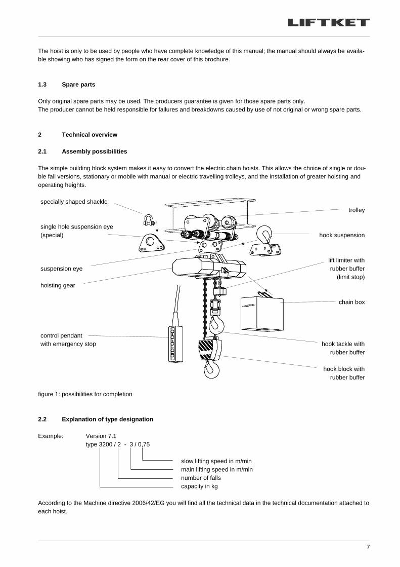
2.1 Assembly possibilities
The simple building block system makes it easy to convert the electric chain hoists. This allows the choice of single or dou-
ble fall versions, stationary or mobile with manual or electric travelling trolleys, and the installation of greater hoisting and
operating heights.
specially shaped shackle
single hole suspension eye
(special)
suspension eye
hoisting gear
control pendant
with emergency stop
trolley
hook suspension
lift limiter with
rubber buffer
(limit stop)
chain box
hook tackle with
rubber buffer
hook block with
rubber buffer
figure 1: possibilities for completion
2.2 Explanation of type designation
Example: Version 7.1
type 3200 / 2 - 3 / 0,75
slow lifting speed in m/min
main lifting speed in m/min
number of falls
capacity in kg
According to the Machine directive 2006/42/EG you will find all the technical data in the technical documentation attached to
each hoist.
8
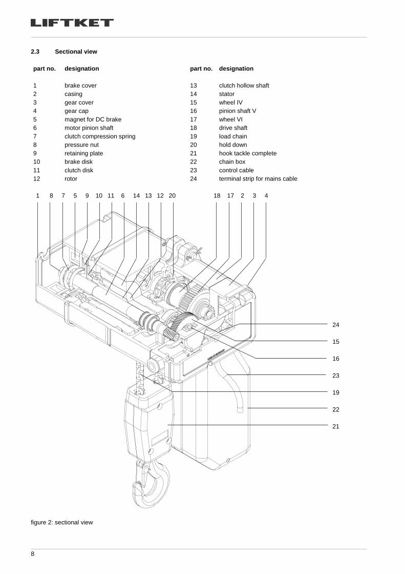
2.3 Sectional view
part no. designation part no. designation
1 brake cover 13 clutch hollow shaft
2 casing 14 stator
3 gear cover 15 wheel IV
4 gear cap 16 pinion shaft V
5 magnet for DC brake 17 wheel VI
6 motor pinion shaft 18 drive shaft
7 clutch compression spring 19 load chain
8 pressure nut 20 hold down
9 retaining plate 21 hook tackle complete
10 brake disk 22 chain box
11 clutch disk 23 control cable
12 rotor 24 terminal strip for mains cable
1 8 7 5 9 10 11 6 14 13 12 20 18 17 2 3 4
figure 2: sectional view
24
15
16
23
19
22
21
9
2.4 Schematic sketch of the load chain configuration
Use manufacturer’s original parts only, as these meet the high stress and service life standards required.
chain sprocket
wheel
hold down
chain guide
chain bag
lift limiter (limit stop)
hook tackle
hook block
3.1 single fall version 3.2 double fall version
figure 3: load chain configuration
3 Assembly
Assembly work should only be carried out by trained specialists in accordance with DGUV V54 (BGV D8) §24.
3.1 Mechanical assembly
3.1.1 Hook tackle
The hook tackle used to attach loads for hoists in single- fall version.
rubber buffer including
washer of steel
threaded bolt
plastic cover with label of load
casing with mark for chain size
4 or 5 in cast part
pressure disk
load hook complete
(incl. pressure bearing)
rubber buffer
2 screws
casing
pressure disk
load hook complete
(incl. pressure bearing)
hook tackle for chains
4×12 and 5×15 mm
hook tackle for chains
7×22, 9×27, 11×31 and 11,3×31 mm
figure 4: assembly of hook tackles
10
During maintenance work the condition of the load hook has to be checked (wear and centre punch spacing, on page hook
certificate). For the hook tackles of the chains 4×12 mm and 5×15 mm the plastic cover has to be checked additionally and
changed if worn. Furthermore, the condition of the pin, which secures the hook nut, the pressure bearing and the safety
latch have to be checked. If required, the axial bearing has to be cleaned and greased.
For the assembly of the hook tackles please tighten the connection screws with the following torques:
hook tackle designation max. load capacity (kg) dimension of screws qty tightening torque (Nm)
hook tackle for chain 4×12 mm 250 - - -
hook tackle for chain 5×15 mm 250 - - -
hook tackle for chain 7×22 mm 1000 M10×40 DIN 912 2 35
hook tackle for chain 9×27 mm 1600 M12×30 DIN 912 2 50
hook tackle for chain 11×31 mm 2500 M12×35 DIN 912 2 50
hook tackle for chain 11.3×31 mm 3200 M12×35 DIN 912 2 50
table 1: tightening torques of connection screws for hook tackles
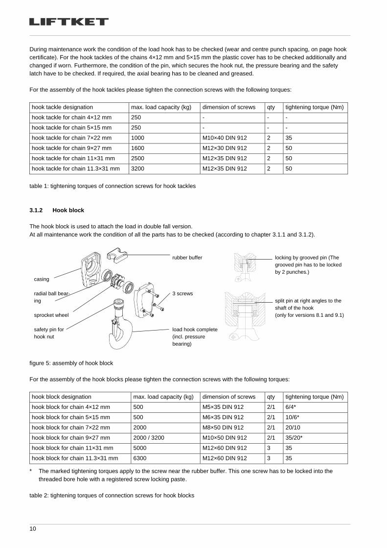
3.1.2 Hook block
The hook block is used to attach the load in double fall version.
At all maintenance work the condition of all the parts has to be checked (according to chapter 3.1.1 and 3.1.2).
casing
radial ball bear-
ing
sprocket wheel
safety pin for
hook nut
rubber buffer
3 screws
load hook complete
(incl. pressure
bearing)
locking by grooved pin (The
grooved pin has to be locked
by 2 punches.)
split pin at right angles to the
shaft of the hook
(only for versions 8.1 and 9.1)
figure 5: assembly of hook block
For the assembly of the hook blocks please tighten the connection screws with the following torques:
hook block designation max. load capacity (kg) dimension of screws qty tightening torque (Nm)
hook block for chain 4×12 mm 500 M5×35 DIN 912 2/1 6/4*
hook block for chain 5×15 mm 500 M6×35 DIN 912 2/1 10/6*
hook block for chain 7×22 mm 2000 M8×50 DIN 912 2/1 20/10
hook block for chain 9×27 mm 2000 / 3200 M10×50 DIN 912 2/1 35/20*
hook block for chain 11×31 mm 5000 M12×60 DIN 912 3 35
hook block for chain 11.3×31 mm 6300 M12×60 DIN 912 3 35
* The marked tightening torques apply to the screw near the rubber buffer. This one screw has to be locked into the
threaded bore hole with a registered screw locking paste.
table 2: tightening torques of connection screws for hook blocks
11
3.1.3 Stationary suspended hoists – basic version
Caution!
Do not use other bolts than the original suspensions bolts. In particular, do not use screws to connect the electric chain hoist to its suspension elements.
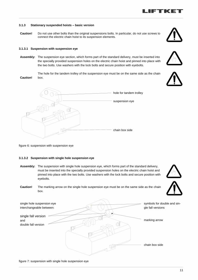
3.1.3.1 Suspension with suspension eye
Assembly:
The suspension eye section, which forms part of the standard delivery, must be inserted into
the specially provided suspension holes on the electric chain hoist and pinned into place with
the two bolts. Use washers with the lock bolts and secure position with eyebolts.
Caution!
The hole for the tandem trolley of the suspension eye must be on the same side as the chain
box.
hole for tandem trolley
suspension eye
chain box side
figure 6: suspension with suspension eye
3.1.3.2 Suspension with single hole suspension eye
Assembly: The suspension with single hole suspension eye, which forms part of the standard delivery,
must be inserted into the specially provided suspension holes on the electric chain hoist and
pinned into place with the two bolts. Use washers with the lock bolts and secure position with
eyebolts.
Caution!
The marking arrow on the single hole suspension eye must be on the same side as the chain
box.
single hole suspension eye
interchangeable between:
single fall version
and
double fall version
symbols for double and sin-
gle fall versions
marking arrow
chain box side
figure 7: suspension with single hole suspension eye
12
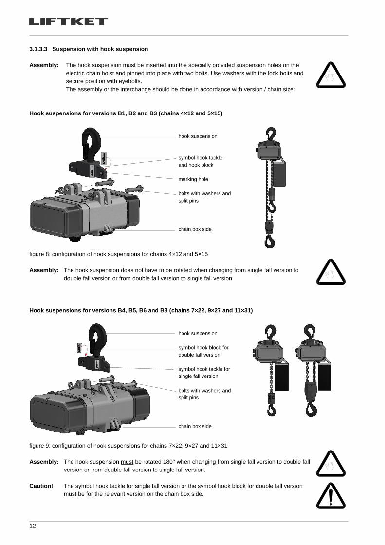
3.1.3.3 Suspension with hook suspension
Assembly: The hook suspension must be inserted into the specially provided suspension holes on the
electric chain hoist and pinned into place with two bolts. Use washers with the lock bolts and
secure position with eyebolts.
The assembly or the interchange should be done in accordance with version / chain size:
Hook suspensions for versions B1, B2 and B3 (chains 4×12 and 5×15)
hook suspension
symbol hook tackle
and hook block
marking hole
bolts with washers and
split pins
chain box side
figure 8: configuration of hook suspensions for chains 4×12 and 5×15
Assembly:
The hook suspension does not have to be rotated when changing from single fall version to
double fall version or from double fall version to single fall version.
Hook suspensions for versions B4, B5, B6 and B8 (chains 7×22, 9×27 and 11×31)
hook suspension
symbol hook block for
double fall version
symbol hook tackle for
single fall version
bolts with washers and
split pins
chain box side
figure 9: configuration of hook suspensions for chains 7×22, 9×27 and 11×31
Assembly:
The hook suspension must be rotated 180° when changing from single fall version to double fall
version or from double fall version to single fall version.
Caution! The symbol hook tackle for single fall version or the symbol hook block for double fall version
must be for the relevant version on the chain box side.
13
3.1.4 Gear ventilation
Having completed assembly, the split washer has to be placed under the oil filler plug (top side of casing) to avoid oil leak-
age due to low/high pressure inside the gearbox. You will find this split washer fastened with a piece of self-adhesive tape
next to the oil filler plug. For outdoor use, high air humidity and big differences in temperatures the use of the split washer is
not recommended.
oil filler plug
split washer
figure 10: oil filler plug
3.1.5 Chain box
3.1.5.1 Mounting of the chain box
plastic chain box canvas chain box Flip bag
figure 11: types of chain boxes
The following chain boxes are made from plastic:
chain dimension [mm] max. filling quantity [m] type of chain box
5×15 10 5/10 7/8
7×22 8
table 3: plastic chain boxes
Chain boxes with bigger capacity are made from canvas material.
The chain box is mounted with screw and self-locking nut. The self-locking nut has to be securely screwed. The self-locking
nut has to be replaced after repeated use when the nylon becomes noticeably worn.
Caution! Ensure that the chain box is sufficient for the amount of chain you are using. The chain dimen-
sion and capacity are shown on the chain box.
Insert the chain end with lift limiter and its rubber buffer loosely into the chain box. After running
the entire chain length through the hoist into the chain box, check that the box is not over-
loaded.
Do not overload the chain box.
14
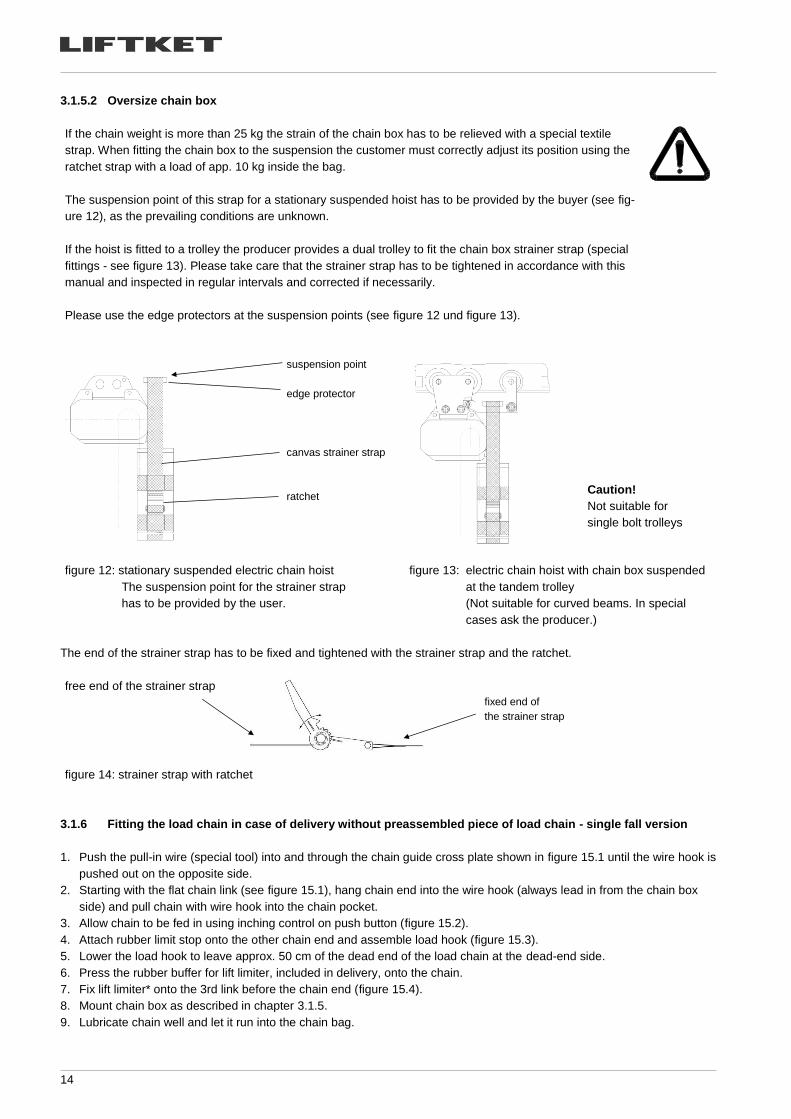
3.1.5.2 Oversize chain box
If the chain weight is more than 25 kg the strain of the chain box has to be relieved with a special textile
strap. When fitting the chain box to the suspension the customer must correctly adjust its position using the
ratchet strap with a load of app. 10 kg inside the bag.
The suspension point of this strap for a stationary suspended hoist has to be provided by the buyer (see fig-
ure 12), as the prevailing conditions are unknown.
If the hoist is fitted to a trolley the producer provides a dual trolley to fit the chain box strainer strap (special
fittings - see figure 13). Please take care that the strainer strap has to be tightened in accordance with this
manual and inspected in regular intervals and corrected if necessarily.
Please use the edge protectors at the suspension points (see figure 12 und figure 13).
suspension point
edge protector
canvas strainer strap
ratchet
figure 12: stationary suspended electric chain hoist
The suspension point for the strainer strap
has to be provided by the user.
figure 13: electric chain hoist with chain box suspended
at the tandem trolley
(Not suitable for curved beams. In special
cases ask the producer.)
The end of the strainer strap has to be fixed and tightened with the strainer strap and the ratchet.
free end of the strainer strap
fixed end of
the strainer strap
figure 14: strainer strap with ratchet
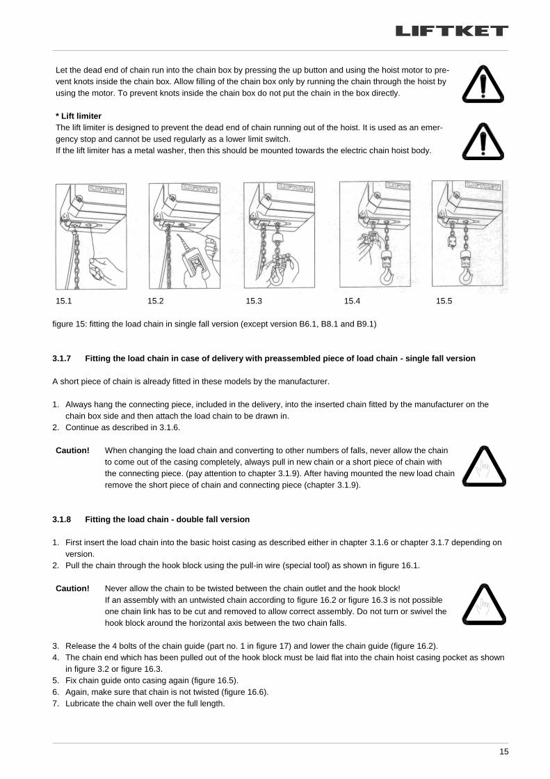
3.1.6 Fitting the load chain in case of delivery without preassembled piece of load chain - single fall version
1. Push the pull-in wire (special tool) into and through the chain guide cross plate shown in figure 15.1 until the wire hook is
pushed out on the opposite side.
2. Starting with the flat chain link (see figure 15.1), hang chain end into the wire hook (always lead in from the chain box
side) and pull chain with wire hook into the chain pocket.
3. Allow chain to be fed in using inching control on push button (figure 15.2).
4. Attach rubber limit stop onto the other chain end and assemble load hook (figure 15.3).
5. Lower the load hook to leave approx. 50 cm of the dead end of the load chain at the dead-end side.
6. Press the rubber buffer for lift limiter, included in delivery, onto the chain.
7. Fix lift limiter* onto the 3rd link before the chain end (figure 15.4).
8. Mount chain box as described in chapter 3.1.5.
9. Lubricate chain well and let it run into the chain bag.
Caution!
Not suitable for
single bolt trolleys
15
Let the dead end of chain run into the chain box by pressing the up button and using the hoist motor to pre-
vent knots inside the chain box. Allow filling of the chain box only by running the chain through the hoist by
using the motor. To prevent knots inside the chain box do not put the chain in the box directly.
* Lift limiter
The lift limiter is designed to prevent the dead end of chain running out of the hoist. It is used as an emer-
gency stop and cannot be used regularly as a lower limit switch.
If the lift limiter has a metal washer, then this should be mounted towards the electric chain hoist body.
15.1 15.2 15.3 15.4 15.5
figure 15: fitting the load chain in single fall version (except version B6.1, B8.1 and B9.1)
3.1.7 Fitting the load chain in case of delivery with preassembled piece of load chain - single fall version
A short piece of chain is already fitted in these models by the manufacturer.
1. Always hang the connecting piece, included in the delivery, into the inserted chain fitted by the manufacturer on the
chain box side and then attach the load chain to be drawn in.
2. Continue as described in 3.1.6.
Caution! When changing the load chain and converting to other numbers of falls, never allow the chain
to come out of the casing completely, always pull in new chain or a short piece of chain with
the connecting piece. (pay attention to chapter 3.1.9). After having mounted the new load chain
remove the short piece of chain and connecting piece (chapter 3.1.9).
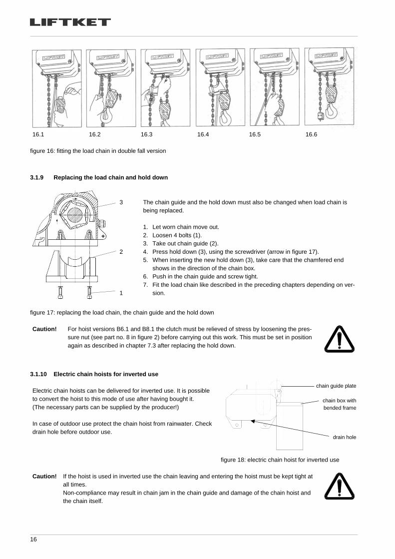
3.1.8 Fitting the load chain - double fall version
1. First insert the load chain into the basic hoist casing as described either in chapter 3.1.6 or chapter 3.1.7 depending on
version.
2. Pull the chain through the hook block using the pull-in wire (special tool) as shown in figure 16.1.
Caution! Never allow the chain to be twisted between the chain outlet and the hook block!
If an assembly with an untwisted chain according to figure 16.2 or figure 16.3 is not possible
one chain link has to be cut and removed to allow correct assembly. Do not turn or swivel the
hook block around the horizontal axis between the two chain falls.
3. Release the 4 bolts of the chain guide (part no. 1 in figure 17) and lower the chain guide (figure 16.2).
4. The chain end which has been pulled out of the hook block must be laid flat into the chain hoist casing pocket as shown
in figure 3.2 or figure 16.3.
5. Fix chain guide onto casing again (figure 16.5).
6. Again, make sure that chain is not twisted (figure 16.6).
7. Lubricate the chain well over the full length.
16
16.1 16.2 16.3 16.4 16.5 16.6
figure 16: fitting the load chain in double fall version
3.1.9 Replacing the load chain and hold down
3
2
1
The chain guide and the hold down must also be changed when load chain is
being replaced.
1. Let worn chain move out.
2. Loosen 4 bolts (1).
3. Take out chain guide (2).
4. Press hold down (3), using the screwdriver (arrow in figure 17).
5. When inserting the new hold down (3), take care that the chamfered end
shows in the direction of the chain box.
6. Push in the chain guide and screw tight.
7. Fit the load chain like described in the preceding chapters depending on ver-
sion.
figure 17: replacing the load chain, the chain guide and the hold down
Caution! For hoist versions B6.1 and B8.1 the clutch must be relieved of stress by loosening the pres-
sure nut (see part no. 8 in figure 2) before carrying out this work. This must be set in position
again as described in chapter 7.3 after replacing the hold down.
3.1.10 Electric chain hoists for inverted use
Electric chain hoists can be delivered for inverted use. It is possible
to convert the hoist to this mode of use after having bought it.
(The necessary parts can be supplied by the producer!)
In case of outdoor use protect the chain hoist from rainwater. Check
drain hole before outdoor use.
figure 18: electric chain hoist for inverted use
Caution! If the hoist is used in inverted use the chain leaving and entering the hoist must be kept tight at
all times.
Non-compliance may result in chain jam in the chain guide and damage of the chain hoist and
the chain itself.
chain guide plate
chain box with
bended frame
drain hole
17
3.2 Electric connections
After having completed the electric installation check them in accordance with the European Regulations EN
60 204-32 or your national regulations.
Details on the control can be seen in the wiring diagram. The electric installation complies with the currently
valid EN 60 204-32.
3.2.1 Mains connection
The mains current supply (main incoming line conductor) must be able to be disconnected at all poles by means of a main
switch (in accordance with EN 60 204-32 section 5.3).
Work on the electric installation may only be carried out by trained specialists and equipment must first be disconnected
from the current supply. In order to ensure the proper functionality of the hoist, the power must be connected to a clockwise
(CW)–turning 3 phase AC supply. Connection has to be corrected if deviations occur. Power connection is correct, when the
hoist button for lifting the load is pressed and the chain hoist moves the load upwards.
Fuses (slowly blowing) at 400 V (3 phase) in front of main switch:
fuse (slowly blowing) model
4 A B1.1
6 A B2 / B3 / B4 / B4.1
10 A B4.2 / B5 / B5.1
B6 / B6.1 / B7 / B7.1 / B7.2 / B8.1 / B9.1
table 4: fuses at 400 V
Check if the mains voltage agrees with that specified on the rating plate.
Connect mains current supply lines and control line in accordance with wiring diagram.
The L1, L2, L3 and PE terminals for the mains connection are located under the gear cap. Line 3 + PE (mini-
mum cross section 1.5 mm2) are necessary for the connection.
After connecting, press button for lift. If the load moves downwards, interchange the L1 and L2 supply cores.
(Disconnect mains supply before!).
Fuses (slowly blowing) at 230 V (single phase) in front of main switch:
fuse (slowly blowing) model
6 A B1.1AK
10 A B2AK
16 A B5AK
table 5: fuses at 230 V
Check if the mains voltage agrees with that specified on the rating plate.
Connect mains current supply lines and control line in accordance with wiring diagram.
The L1, N and PE terminals for the mains connection are located under the gear cap. Lines 2 + PE (mini-
mum cross section 2.5 mm2) are necessary for the connection.
After connecting, press button for lift. If the load moves downwards, interchange the L and N supply cores.
(Disconnect mains supply before!).
If the control unit is equipped with an emergency stop (EN 60 204-32) you will find this button on your control
pendant. In accordance with European Regulations the main switch has to be installed in addition to the
emergency stop and it has to be turned off after daily operation.
18
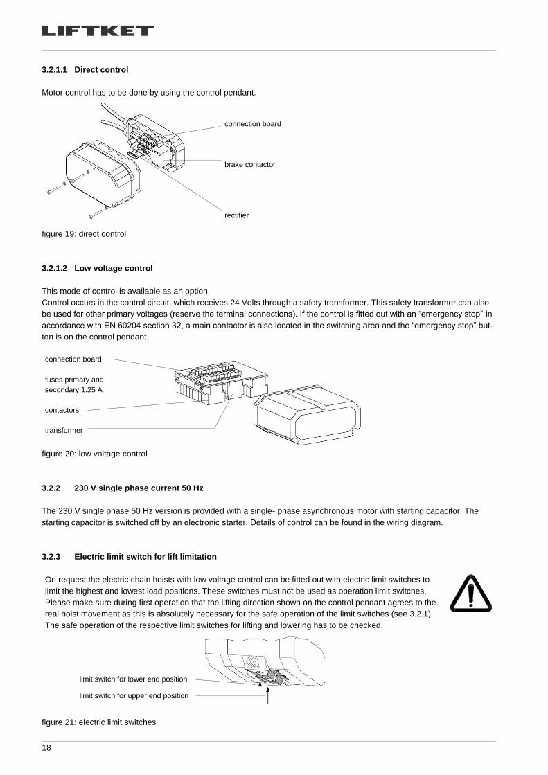
3.2.1.1 Direct control
Motor control has to be done by using the control pendant.
connection board
brake contactor
rectifier
figure 19: direct control
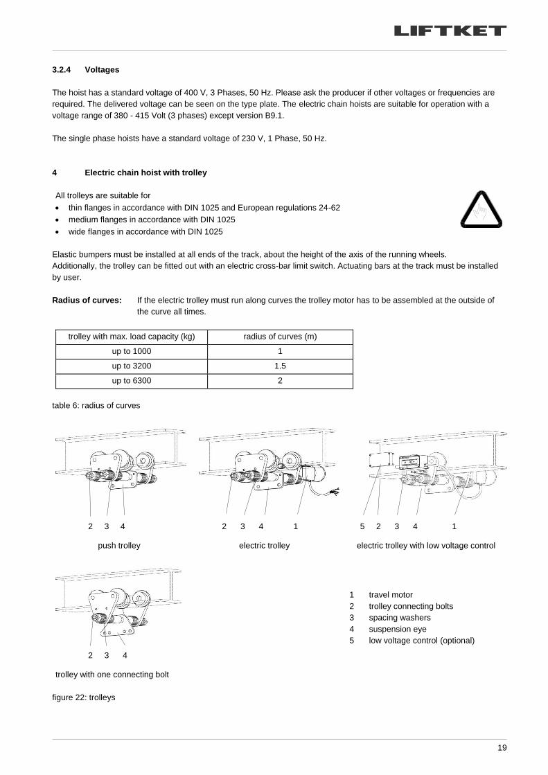
3.2.1.2 Low voltage control
This mode of control is available as an option.
Control occurs in the control circuit, which receives 24 Volts through a safety transformer. This safety transformer can also
be used for other primary voltages (reserve the terminal connections). If the control is fitted out with an “emergency stop” in
accordance with EN 60204 section 32, a main contactor is also located in the switching area and the “emergency stop” but-
ton is on the control pendant.
connection board
fuses primary and
secondary 1.25 A
contactors
transformer
figure 20: low voltage control
3.2.2 230 V single phase current 50 Hz
The 230 V single phase 50 Hz version is provided with a single- phase asynchronous motor with starting capacitor. The
starting capacitor is switched off by an electronic starter. Details of control can be found in the wiring diagram.
3.2.3 Electric limit switch for lift limitation
On request the electric chain hoists with low voltage control can be fitted out with electric limit switches to
limit the highest and lowest load positions. These switches must not be used as operation limit switches.
Please make sure during first operation that the lifting direction shown on the control pendant agrees to the
real hoist movement as this is absolutely necessary for the safe operation of the limit switches (see 3.2.1).
The safe operation of the respective limit switches for lifting and lowering has to be checked.
figure 21: electric limit switches
limit switch for lower end position
limit switch for upper end position
19
3.2.4 Voltages
The hoist has a standard voltage of 400 V, 3 Phases, 50 Hz. Please ask the producer if other voltages or frequencies are
required. The delivered voltage can be seen on the type plate. The electric chain hoists are suitable for operation with a
voltage range of 380 - 415 Volt (3 phases) except version B9.1.
The single phase hoists have a standard voltage of 230 V, 1 Phase, 50 Hz.
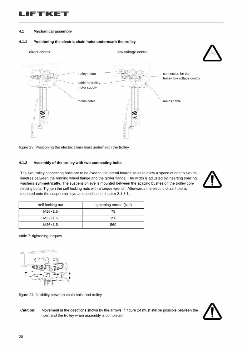
4 Electric chain hoist with trolley
All trolleys are suitable for
• thin flanges in accordance with DIN 1025 and European regulations 24-62
• medium flanges in accordance with DIN 1025
• wide flanges in accordance with DIN 1025
Elastic bumpers must be installed at all ends of the track, about the height of the axis of the running wheels.
Additionally, the trolley can be fitted out with an electric cross-bar limit switch. Actuating bars at the track must be installed
by user.
Radius of curves: If the electric trolley must run along curves the trolley motor has to be assembled at the outside of
the curve all times.
trolley with max. load capacity (kg) radius of curves (m)
up to 1000 1
up to 3200 1.5
up to 6300 2
table 6: radius of curves
2 3 4 2 3 4 1 5 2 3 4 1
push trolley electric trolley electric trolley with low voltage control
1 travel motor
2 trolley connecting bolts
3 spacing washers
4 suspension eye
5 low voltage control (optional)
2 3 4
trolley with one connecting bolt
figure 22: trolleys
20
4.1 Mechanical assembly
4.1.1 Positioning the electric chain hoist underneath the trolley
direct control
low voltage control
trolley motor
cable for trolley
motor supply
mains cable
connection for the
trolley low voltage control
mains cable
figure 23: Positioning the electric chain hoist underneath the trolley
4.1.2 Assembly of the trolley with two connecting bolts
The two trolley connecting bolts are to be fixed to the lateral boards so as to allow a space of one to two mil-
limetres between the running wheel flange and the girder flange. The width is adjusted by inserting spacing
washers symmetrically. The suspension eye is mounted between the spacing bushes on the trolley con-
necting bolts. Tighten the self-locking nuts with a torque wrench. Afterwards the electric chain hoist is
mounted onto the suspension eye as described in chapter 3.1.3.1.
self-locking nut tightening torque (Nm)
M16×1.5 75
M22×1.5 150
M36×1.5 560
table 7: tightening torques
figure 24: flexibility between chain hoist and trolley
Caution!
Movement in the directions shown by the arrows in figure 24 must still be possible between the
hoist and the trolley when assembly is complete.!
21
4.1.3 Assembly of a trolley with one connecting bolt
The electric trolley with one connecting bolt is assembled as described in chapter 4.1.2.
Afterwards the electric chain hoist is mounted onto the suspension eye as described in chapter 3.1.3.2
4.2 Electric trolleys with compensation of weight
4.2.1 Counterwheels
figure 25: counterwheels for electric trolley
If electric trolleys, especially with double speed, are used on girders with a very small width it may be necessary to provide
a device, which prevents tipping up of the trolley.
This unit can be retrofitted to each trolley. It does not influence any features of a standard trolley, but cannot be used if the
beam is equipped with connection plates welded underneath the beam.
Assembly guide:
• The unit has to be fitted in threaded holes at all the side-plates with screws M8×20.
• The counterwheels have to be adjusted that it touches the bottom of the girder.
• The screws, which adjust the counterwheels, have to be tightened to a torque of 40 Nm.
• To check the behaviour, the trolley should be travelled along the whole beam.
• The low voltage control box (if required) has to be assembled to the other side of the trolley as usual with two screws
M8×10 (see figure 22).
4.2.2 Counterweight
figure 26: counterweight for electric trolley
If electric trolleys, especially with double speed, are used on girders with a very small width it may be necessary to provide
a device, which prevents tipping up of the trolley. This unit can be retrofitted to each trolley.
This kit does not influence any features of a standard trolley.
The replacement of the counterwheels by counterweight will be done in progress.
22
4.3 Electric connection of electric trolleys
4.3.1 Direct control
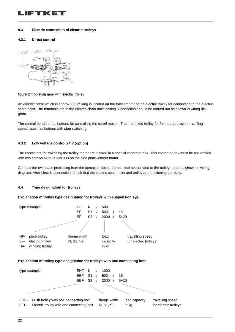
figure 27: hoisting gear with electric trolley
An electric cable which is approx. 0.5 m long is located on the travel motor of the electric trolley for connecting to the electric
chain hoist. The terminals are in the electric chain hoist casing. Connection should be carried out as shown in wiring dia-
gram.
The control pendant has buttons for controlling the travel motion. The motorized trolley for fast and precision travelling
speed rates has buttons with step switching.
4.3.2 Low voltage control 24 V (option)
The contactors for switching the trolley motor are located in a special contactor box. This contactor box must be assembled
with two screws M8×10 DIN 933 on the side plate without motor.
Connect the two leads protruding from the contactor box to the terminal section and to the trolley motor as shown in wiring
diagram. After electric connection, check that the electric chain hoist and trolley are functioning correctly.
4.4 Type designation for trolleys
Explanation of trolley type designation for trolleys with suspension eye:
type-example: HF N / 500
EF S1 / 500 / 16
EF S2 / 2000 / 5+20
HF- push trolley flange width load travelling speed
EF- electric trolley N, S1, S2 capacity for electric trolleys
HA- winding trolley in kg
Explanation of trolley type designation for trolleys with one connecting bolt:
type-example: EHF N / 1000
EEF S1 / 500 / 16
EEF S2 / 2000 / 5+20
EHF- Push trolley with one connecting bolt flange width load capacity travelling speed
EEF- Electric trolley with one connecting bolt N, S1, S2 in kg for electric trolleys
23
5 Tests
Use of the electric chain hoist is possible in accordance with accident prevention regulations for:
• Wind lasses, lifting and pulling equipment DGUV V54 (BGV D8)
• Cranes DGUV V52 (BGV D6)
The dynamic and static tests are accomplished acc. to EC Machinery Directive by manufacturer.
5.1 Test when used according to DGUV V54 (BGV D8) § 23
A trained specialist must test the equipment before starting operation for the first time and after extensive alterations.
5.2 Test when used according to DGUV V52 (BGV D6) § 25
An authorized expert must test the cranes before starting operation for the first time and after extensive alterations. The
electric chain hoists are type tested.
5.3 Regular tests
• A trained specialist must test the equipment, cranes and supporting structures once a year. It may be necessary to carry
out tests more often if the operating conditions are very demanding, that means for example high percentage of use with
full load, dusty or aggressive environment, high duty rate, high number of operation cycles.
• Only experts appointed by the trade associations and experts from the Technical Control Association are considered
qualified to test cranes.
• Trained specialists are highly qualified specialist personnel or the manufacturer’s after-sales assemblers.
24
6 Directions and prohibitions for use
6.1 Directions for use
• The load may only then be moved if it is slung securely and no person is standing near enough to be at
risk and when the operator has received an all clear signal from the person slinging the load.
• All electric chain hoists are suitable for an environment temperature of –20°C to +40°C as standard.
For use in higher environmental temperature the duty rate has to be reduced accordingly.
• The protection class is IP 54 as standard.
• The motors are manufactured according to the requirement of Insulation Class F.
• The load must be placed vertically under the electric hoist before lifting.
• The motion directions are indicated with symbols on the control buttons.
• Do not turn the chain over edges.
• Only the load, the hook block or hook tackle may be pulled to move an electric chain hoist with manual travelling gear.
• Consult the manufacturer or supplier, if the hoist is to be used in aggressive environment (for instance acid or alkaline
or dusty environment or to transport inflammable or other dangerous loads).
• For use for molten metals and similar hazardous materials – please ask the producer.
• Don’t lower the double fall hook if the chain gets slack.
• The chain leaving and entering the hoist in inverted use must be kept tight at all times.
• Repair work has to be done only if mains supply is switched off and no load is suspended on the hook.
• After switching off the emergency stop the reason for this failure has to be found out by trained people and the hoist
can only be used if all possible failures are removed.
• Lifting the load from the ground has to be done with the lowest possible speed. Before doing this slack sling chains or
ropes have to be tightened carefully.
• Cranes in outdoor use require a roof for the park position.
• The S.W.L. of the trolley must be equal to or greater than the S.W.L. shown on the load-hoisting accessory.
6.2 Prohibitions for use
• Inching mode
• Permanent run against the rubber washers of the lowest and highest hook position or lifting
loads with bigger weight as marked on the specification plate
• Transporting people
• Using the hoist with people being underneath the load
• Starting initial operation before an expert or a trained specialist has inspected the equipment
• Moving loads heavier than the nominal load
• Pulling loads which are tilted or dragging loads
• Tearing off loads
• Removing the cover of vessels under vacuum
• Moving trolley by pulling control pendant or control cable, even if these are relieved of strain
• Carrying out repairs without disconnecting the current supply and without special knowledge
• Use of hoists with worn rubber elements or without rubber buffer on hook tackle, hook block or lift limiter
• Using the lifting chain to sling the loads
• Operation with twisted chain, caused by swivelled hook block or wrong mounted fix chain end
• Using a lifting chain, which is longer than the chain box capacity stated under the chain box
• Using the hoist with higher duty rate as marked on the specification plate
• Using the hoist without having done the regular inspection
• Operation after the S.W.P. is exceeded
• When the hoist with trolley is used at girders, which are lower than or equal to 2.5 m above working platforms it is not
allowed to grab on the trolley travel girder. Touching the chain during operation is not allowed.
25
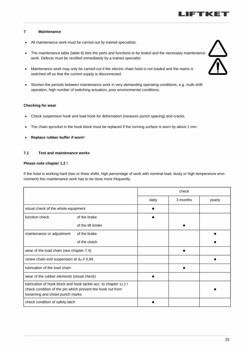
7 Maintenance
• All maintenance work must be carried out by trained specialists.
• The maintenance table (table 8) lists the parts and functions to be tested and the necessary maintenance
work. Defects must be rectified immediately by a trained specialist
• Maintenance work may only be carried out if the electric chain hoist is not loaded and the mains is
switched off so that the current supply is disconnected.
• Shorten the periods between maintenance work in very demanding operating conditions, e.g. multi-shift
operation, high number of switching actuation, poor environmental conditions.
Checking for wear
• Check suspension hook and load hook for deformation (measure punch spacing) and cracks.
• The chain sprocket in the hook block must be replaced if the running surface is worn by about 1 mm.
• Replace rubber buffer if worn!
7.1 Test and maintenance works
Please note chapter 1.2 !
If the hoist is working hard (two or three shifts, high percentage of work with nominal load, dusty or high temperature envi-
ronment) this maintenance work has to be done more frequently.
check
daily 3 months yearly
visual check of the whole equipment ●
function check of the brake ●
of the lift limiter ●
maintenance or adjustment of the brake ●
of the clutch ●
wear of the load chain (see chapter 7.4) ●
renew chain end suspension at dm ≤ 0,9d ●
lubrication of the load chain ●
wear of the rubber elements (visual check) ●
lubrication of hook block and hook tackle acc. to chapter 11.2 /
check condition of the pin which prevent the hook nut from
loosening and chisel punch marks
●
check condition of safety latch ●
26
check
daily 3 months yearly
universal checks of all screws ●
hold down, chain guide ●
safety devices ●
check of the condition and safe positioning of the chain box and
condition of the canvas material as well ●
check of the electric cable, power cable and control pendant ●
check of the trolleys and wheels ●
table 8: test and maintenance works
The electric chain hoist is designed in accordance with FEM 9.511. According to FEM 9.755 the residual safe
working period must be established and documented every year.
If the residual safe working period calculations are fully available, then the electric chain hoist must be sub-
jected to a general overhaul when the theoretical safe working period (maximum safe working period) has
been reached.
If the usage of the electric chain hoist is not certified, then pursuant to FEM 9.755 the general overhaul must
be carried out not later than after 10 years.
7.2 Maintenance and adjustment of the brake
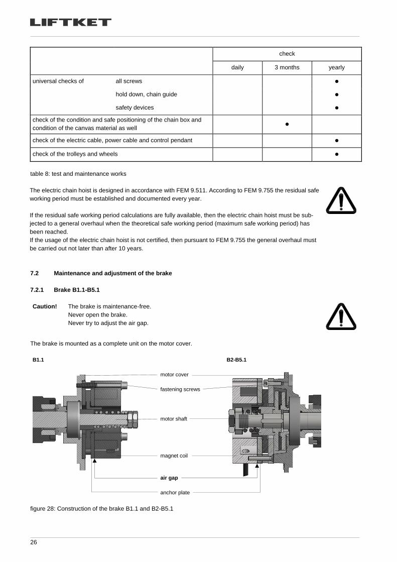
7.2.1 Brake B1.1-B5.1
Caution! The brake is maintenance-free.
Never open the brake.
Never try to adjust the air gap.
The brake is mounted as a complete unit on the motor cover.
B1.1
motor cover
fastening screws
motor shaft
magnet coil
air gap
anchor plate
B2-B5.1
figure 28: Construction of the brake B1.1 and B2-B5.1
27
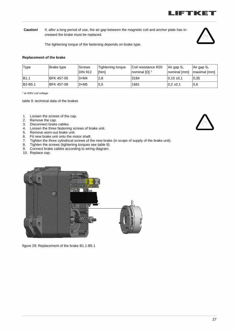
Caution! If, after a long period of use, the air gap between the magnetic coil and anchor plate has in-
creased the brake must be replaced.
The tightening torque of the fastening depends on brake type.
Replacement of the brake
Type Brake type Screws
DIN 912
Tightening torque
[Nm]
Coil resistance R20
nominal [Ω] 1
Air gap SL
nominal [mm]
Air gap SL
maximal [mm]
B1.1 BFK 457-05 3×M4 2,8 3184 0,15 ±0,1 0,35
B2-B5.1 BFK 457-08 3×M5 5,5 1681 0,2 ±0,1 0,6
1 at 205V coil voltage
table 9: technical data of the brakes
1. Loosen the screws of the cap. 2. Remove the cap. 3. Disconnect brake cables. 4. Loosen the three fastening screws of brake unit. 5. Remove worn-out brake unit. 6. Fit new brake unit onto the motor shaft. 7. Tighten the three cylindrical screws of the new brake (in scope of supply of the brake unit). 8. Tighten the screws (tightening torques see table 9). 9. Connect brake cables according to wiring diagram. 10. Replace cap.
figure 29: Replacement of the brake B1.1-B5.1
28
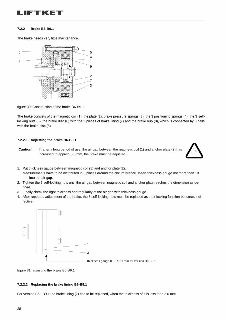
7.2.2 Brake B6-B9.1
The brake needs very little maintenance.
6
8
5
4
1
9
2
7
3
figure 30: Construction of the brake B6-B9.1
The brake consists of the magnetic coil (1), the plate (2), brake pressure springs (3), the 3 positioning springs (4), the 3 self-
locking nuts (5), the brake disc (6) with the 2 pieces of brake lining (7) and the brake hub (8), which is connected by 3 balls
with the brake disc (6).
7.2.2.1 Adjusting the brake B6-B9.1
Caution!
If, after a long period of use, the air gap between the magnetic coil (1) and anchor plate (2) has
increased to approx. 0.8 mm, the brake must be adjusted.
1. Put thickness gauge between magnetic coil (1) and anchor plate (2).
Measurements have to be distributed in 3 places around the circumference. Insert thickness gauge not more than 10
mm into the air gap.
2. Tighten the 3 self-locking nuts until the air gap between magnetic coil and anchor plate reaches the dimension as de-
fined.
3. Finally check the right thickness and regularity of the air gap with thickness gauge.
4. After repeated adjustment of the brake, the 3 self-locking nuts must be replaced as their locking function becomes inef-
fective.
1
2
thickness gauge 0.6 +/-0.1 mm for version B6-B9.1
figure 31: adjusting the brake B6-B9.1
7.2.2.2 Replacing the brake lining B6-B9.1
For version B6 - B9.1 the brake lining (7) has to be replaced, when the thickness of it is less than 3.0 mm.
29
7.2.3 Electric control of brake - function
The brake is supplied through a rectifier circuit.
It operates according to the fail-safe principle. If there is a power failure, the brake acts automatically so that the load is held
securely in every position.
To shorten the braking distance the brake is operated in a DC circuit.
The different methods of connection in direct control and low voltage control can be seen in the respective wiring diagram.
7.2.4 Checking brake functioning
When braking the nominal load during the lowering process, the load should be braked after approx. two
chain link lengths and the load should not be braked in a jerking manner.
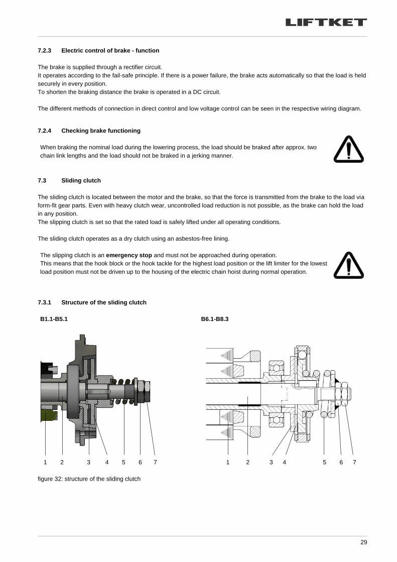
7.3 Sliding clutch
The sliding clutch is located between the motor and the brake, so that the force is transmitted from the brake to the load via
form-fit gear parts. Even with heavy clutch wear, uncontrolled load reduction is not possible, as the brake can hold the load
in any position.
The slipping clutch is set so that the rated load is safely lifted under all operating conditions.
The sliding clutch operates as a dry clutch using an asbestos-free lining.
The slipping clutch is an emergency stop and must not be approached during operation.
This means that the hook block or the hook tackle for the highest load position or the lift limiter for the lowest
load position must not be driven up to the housing of the electric chain hoist during normal operation.
7.3.1 Structure of the sliding clutch
B1.1-B5.1 B6.1-B8.3
1 2 3 4 5 6 7 1 2 3 4 5 6 7
figure 32: structure of the sliding clutch
30
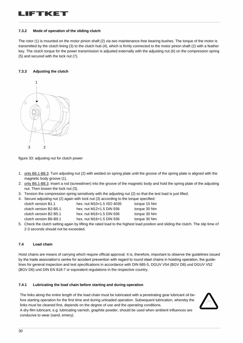
7.3.2 Mode of operation of the sliding clutch
The rotor (1) is mounted on the motor pinion shaft (2) via two maintenance-free bearing bushes. The torque of the motor is
transmitted by the clutch lining (3) to the clutch hub (4), which is firmly connected to the motor pinion shaft (2) with a feather
key. The clutch torque for the power transmission is adjusted externally with the adjusting nut (6) on the compression spring
(5) and secured with the lock nut (7).
7.3.3 Adjusting the clutch
1
3 2
figure 33: adjusting nut for clutch power
1. only B6.1-B8.3: Turn adjusting nut (2) with welded on spring plate until the groove of the spring plate is aligned with the
magnetic body groove (1).
2. only B6.1-B8.3: Insert a rod (screwdriver) into the groove of the magnetic body and hold the spring plate of the adjusting
nut. Then loosen the lock nut (3).
3. Tension the compression spring sensitively with the adjusting nut (2) so that the test load is just lifted.
4. Secure adjusting nut (2) again with lock nut (3) according to the torque specified:
clutch version B1.1 hex. nut M10×1.5 ISO 4035 torque 15 Nm
clutch version B2-B5.1 hex. nut M12×1.5 DIN 936 torque 30 Nm
clutch version B2-B5.1 hex. nut M16×1.5 DIN 936 torque 30 Nm
clutch version B6-B9.1 hex. nut M16×1.5 DIN 936 torque 30 Nm
5. Check the clutch setting again by lifting the rated load to the highest load position and sliding the clutch. The slip time of
2-3 seconds should not be exceeded.
7.4 Load chain
Hoist chains are means of carrying which require official approval. It is, therefore, important to observe the guidelines issued
by the trade association’s centre for accident prevention with regard to round steel chains in hoisting operation, the guide-
lines for general inspection and test specifications in accordance with DIN 685-5, DGUV V54 (BGV D8) und DGUV V52
(BGV D6) und DIN EN 818-7 or equivalent regulations in the respective country.
7.4.1 Lubricating the load chain before starting and during operation
The links along the entire length of the load chain must be lubricated with a penetrating gear lubricant oil be-
fore starting operation for the first time and during unloaded operation. Subsequent lubrication, whereby the
links must be cleaned first, depends on the degree of use and the operating conditions.
A dry-film lubricant, e.g. lubricating varnish, graphite powder, should be used when ambient influences are
conducive to wear (sand, emery).
31
7.4.2 Testing of wear of the load chain
The continuous monitoring of the load chain is compulsory according to DIN 685-5 and the accident preven-
tion regulations in DGUV V54 (BGV D8) § 27. The load chain must be tested before starting operation and
after approx. 200 operating hours or 10,000 load cycles under normal conditions or more often under de-
manding and severe conditions. Testing must cover checking links, particularly at their points of contact, for
wear, cracks, deformation and other damages.
The chain must be replaced:
• if the nominal thickness at the points of contact is reduced by 10%,
• if a chain link is elongated by 5%, or an eleven links piece of chain is elongated by 2%,
• if the links are rigid.
The chain guide and hold down must also be replaced along with the chain.
Caution! For replacement of chain only use original spare chain obtained from the manufacturer or his
approved service agent.
7.4.3 Measuring wear and replacing chain
chain dimensions mm link dimension 4×12 5×15 7×22 9×27 11×31 11.3×31
measure 1 link inside
max. measurement t
11 chain links
12.6
134.6
15.8
168.3
23.1
246.8
28.4
302.9
32.6
347.8
32.6
347.8
measure chain link diameter
2
ddd
21m
+=
min. measurement dm = 0.9d
3.6
4.5
6.3
8.1
9.9
10.2
table 10 measurement of chain dimensions
See chapter 3.1.6 and following for how to change the chain.
7.4.4 Measuring wear and replacing load hook
According to DIN 15401 part 1 load hooks have to be replaced if the length between the chisel punch marks (dimension Y)
widened more than 10%. The permissible values are shown on the hook certificate in the ‘Inspection book’.
7.5 Maintenance work on trolley
The checks and maintenance work on the electric trolley and push trolley have to be done in accordance
with table 8 in chapter 7.1.
The brake is maintenance-free.
32
8 Duty rate of an electric chain hoist (acc. to FEM 9.683)
Caution!
The duty rate and the number of operating cycles in one hour must not be higher than as shown
on the specification plate of the hoist or in a technical data table.
(European regulation FEM 9.683).
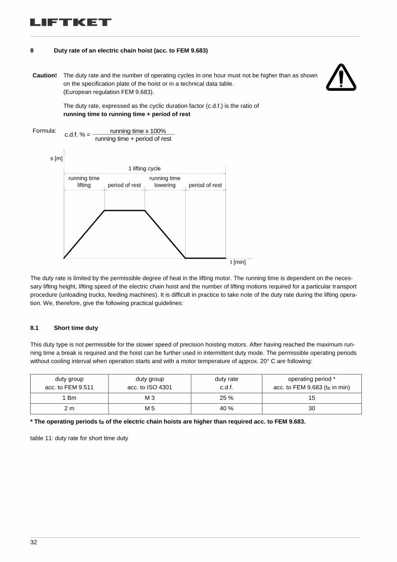
The duty rate, expressed as the cyclic duration factor (c.d.f.) is the ratio of
running time to running time + period of rest
Formula: c.d.f. % =
running time x 100%
running time + period of rest
The duty rate is limited by the permissible degree of heat in the lifting motor. The running time is dependent on the neces-
sary lifting height, lifting speed of the electric chain hoist and the number of lifting motions required for a particular transport
procedure (unloading trucks, feeding machines). It is difficult in practice to take note of the duty rate during the lifting opera-
tion. We, therefore, give the following practical guidelines:
8.1 Short time duty
This duty type is not permissible for the slower speed of precision hoisting motors. After having reached the maximum run-
ning time a break is required and the hoist can be further used in intermittent duty mode. The permissible operating periods
without cooling interval when operation starts and with a motor temperature of approx. 20° C are following:
duty group
acc. to FEM 9.511
duty group
acc. to ISO 4301
duty rate
c.d.f.
operating period *
acc. to FEM 9.683 (tB in min)
1 Bm M 3 25 % 15
2 m M 5 40 % 30
* The operating periods tB of the electric chain hoists are higher than required acc. to FEM 9.683.
table 11: duty rate for short time duty
running time
lifting period of rest
running time
lowering period of rest
1 lifting cycle
s [m]
t [min]
33
8.2 Intermittent duty
Operation must be interrupted whenever the highest permissible operating time is reached. The following breaks are neces-
sary depending on the duty rate c.d.f. of the electric chain hoist:
duty rate c.d.f. break (min)
15 % 5 times running time
20 % 4 times running time
25 % 3 times running time
30 % 2.5 times running time
40 % 1.5 times running time
50 % 1 times running time
60 % 0.66 times running time
table 12: intermittent duty
8.3 Example
The electric chain hoist type 500/1-10 is to lift loads of 500 kg to a height of 5 m.
At the beginning of the lifting operation the electric chain hoist has a temperature of approx. 20 °C.
Performance data: load capacity 500 kg lifting speed 10 m/min
duty rate 40 % duty group of the hoist 2 m
c.d.f = = 1 min for each lifting cycle
During the operation without break (short-time duty = max. 30 minutes without break acc. to FEM 9.683) max. 30 lifting cy-
cles are possible.
After 30 minutes of operating time, 1.5 minutes break for each minute of operating time must be taken (i.e. 1.5 times the
operating time). This break is usually necessary for slinging and taking off loads.
Caution!
Cooling periods are imperative for extreme lifting heights (from 10 metres on). Low lifting speed
should only be used for precise lowering and lifting. It is not suitable when greater lifting heights
shall be driven through.
Option! To protect the lifting motor a thermal overload device is offered as an option (24 Volts low volt-
age control is required!).
9 Duty rate of the electric trolleys (acc. to FEM 9.683)
If the hoist is equipped with an electric trolley the operators have to take care of the duty rating of the trolley as well. This
especially applies to very long track systems.
electric trolley type duty rate (%) running time (min)
trolleys with single travelling speed 40 % 30
trolleys with double travelling speed 40/20% 30*
* The ratings are relevant for the fast travelling speed.
table 13: duty rate for the electric trolleys
5 m lifting + 5 m lowering
10 m/min lifting speed
34
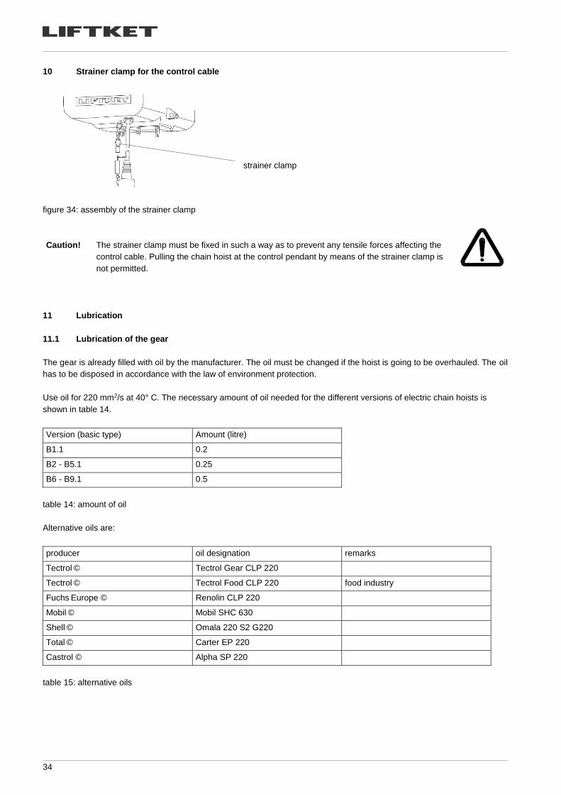
10 Strainer clamp for the control cable
strainer clamp
figure 34: assembly of the strainer clamp
Caution!
The strainer clamp must be fixed in such a way as to prevent any tensile forces affecting the
control cable. Pulling the chain hoist at the control pendant by means of the strainer clamp is
not permitted.
11 Lubrication
11.1 Lubrication of the gear
The gear is already filled with oil by the manufacturer. The oil must be changed if the hoist is going to be overhauled. The oil
has to be disposed in accordance with the law of environment protection.
Use oil for 220 mm2/s at 40° C. The necessary amount of oil needed for the different versions of electric chain hoists is
shown in table 14.
Version (basic type) Amount (litre)
B1.1 0.2
B2 - B5.1 0.25
B6 - B9.1 0.5
table 14: amount of oil
Alternative oils are:
producer oil designation remarks
Tectrol © Tectrol Gear CLP 220
Tectrol © Tectrol Food CLP 220 food industry
Fuchs Europe © Renolin CLP 220
Mobil © Mobil SHC 630
Shell © Omala 220 S2 G220
Total © Carter EP 220
Castrol © Alpha SP 220
table 15: alternative oils
35
11.2 Lubrication of the chain
The following lubricants are recommended for lubrication of chain depending on operating conditions:
producer lubricant designation remarks
Tectrol © Kettenöl K50
Tectrol © Tectrol Multi Spray XL dry lubricant
Tectrol © Food Kettenspray food industry
Klüber © Klüberoil CA 1-460
Klüber © Klüberoil 4UH 1-1500 food industry
Castrol © Optimol Viscogen KL300
Fuchs Lubritech © Ceplattyn 300 dry lubricant
Fuchs Lubritech © Stabylan 2001
Fuchs Lubritech © Stabylan 5006
Fuchs Lubritech © Decordyn 350
Fuchs Europe © Renolit SO-GFB grease
Klüber © Microlube GB 00 grease
Table 16: Alternative lubricants for chain
11.3 Lubrication of the hook block and hook tackle
Lubricate the anti-friction bearings on the hook and the chain sprocket after approx. 20,000 lifting cycles or
once a year, if in heavy use shorten the interval, use a special anti-friction bearing grease.
Lubricants recommended for lubrication of bearings:
producer lubricant designation
Tectrol © Tectrol Spezial-Fett LX 2
Fuchs Europe © Renolit Duraplex EP3
Fuchs Lubritech © Lagermeister LX EP2
Table 17: Alternative lubricant for bearing
11.4 Lubrication of the trolleys
The pinion, the geared wheels and the roller bearings of the electric trolley have to be lubricated with grease
once a year or after 10,000 driving cycles, if in heavy use the interval has to be shortened.
Lubricants recommended for lubrication of gearing:
producer lubricant designation
Tectrol © Tectrol Spezial-Fett LX 2
Fuchs Europe © Renolit Duraplex EP3
Fuchs Lubritech © Lagermeister LX EP2
Table 18: Alternative lubricant for gearing of the trolley
36
11.5 Auxiliary materials
Following threadlocking pastes are recommended for threadlocking of screws:
producer designation characteristics
Weicon Weiconlock AN 302-42 locking paste, appropriate to connections up to M36,
breakaway dismantle torque min. 14 -18 Nm
Henkel Loctite 243 locking paste, appropriate to connections up to M20,
breakaway dismantle torque min. 20 Nm
table 19: locking pastes
12 Measures to be taken at the end of the S.W.P.
After the hoist or its components have reached the end of the S.W.P. the hoist or its components have to be overhauled or
to be taken finally out of operation.
The parts have to be disposed in accordance to the laws of environment protection. Metals, rubber, plastics have to be dis-
posed or recycled separately.
37
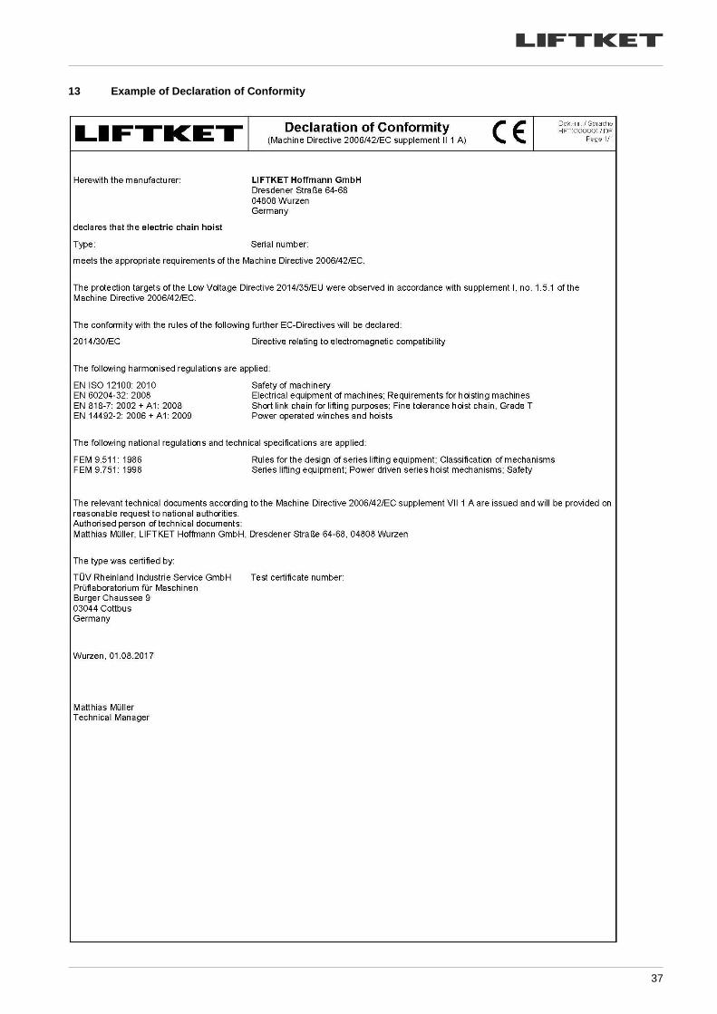
13 Example of Declaration of Conformity
38
14 Example of Declaration of Incorporation

39

40
The operators who have been instructed to use this hoist and have read the manual and especially the safety advice.
Name, Surname Date Signature
The advice contained within this manual should be implemented by the appropriate skilled and qualified operators of indus-
trial hoists. Further information for other fields of operation are not considered herewith.
If changes to the normal operations are discovered (such as unusual noise, vibrations, higher input current or frequently
blowing fuses) the hoist has to be taken out of operation and the load area has to be isolated because a fault is possible,
which can result in danger to people or goods. The operator or owner of the hoist has to call a trained specialist to repair
the hoist.


![GEOG 3425 Urban Sustainabilityeboschma/GEOG3425.pdfReadings: - [W + B] Ch. 1 The Three Magnets ... GEOG 3425 Urban Sustainability Course Calendar Spring Quarter 2014 2 Th, April 10](https://img.pdfslide.us/doc/110x75/601246268d419962c00addc2/geog-3425-urban-sustainability-eboschmageog3425pdf-readings-w-b-ch-1-the.jpg)