Embed Size (px)
Citation preview
Global Leaders in Specialized
Lifting Equipment!
68 TONNE MOBILFT by
LIFT SYSTEMS, INC.
MOBILIFT
68 TONNE
STANDARD EQUIPMENT
OPTIONAL EQUIPMENT
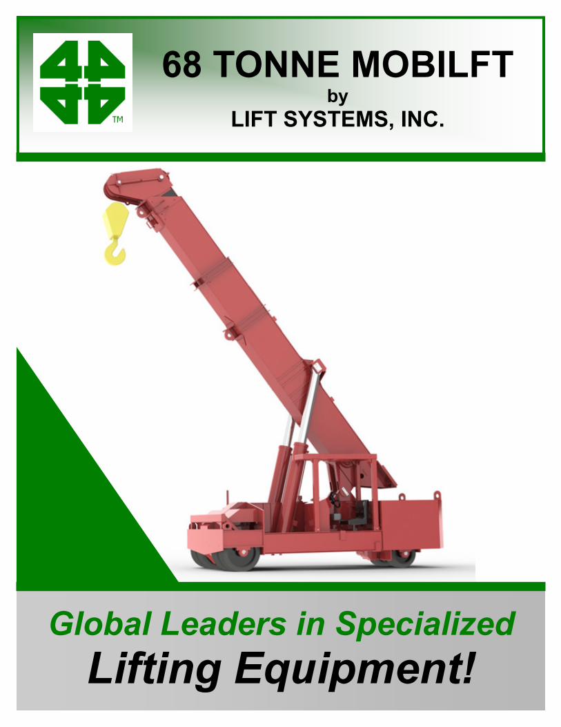
ENGINE: Cummins Diesel Engine: QSB3.3P 81 Kw (108 hp) intermittent @ 2200 rpm U.S. EPA Tier 3 CARB Tier 3 EU Stage III Torque @ 1600 rpm, 415 N-m (306 ft-lbs) PUMP: Sundstrand 90 series drive pump CONTROL SYSTEM: CARL (Computer Assisted Remote Lifting) Control System. Monitors Boom Angle, Boom Extension, Pressure, Counterweight Load Pin. Automatic Shutdown for overload conditions. Large easy to read display screen with push button navigation and dial adjustment. CONTROLS: Separate controls for each function. Combination of foot pedal, joystick, and push button controls allows for multiple functions to be performed at the same time. DRIVE: Poclain MK35 drive motors (qty. 3) (2) in front, (1) in rear steering box. WHEELS: Front: qty. (4) Diameter: 711mm Width: (2) @ 406mm and (2) @ 254mm Rear: qty. (2) Diameter: 711mm Width: 406mm Replaceable polyurethane composition STEERING: 90 degree steering of rear wheels. OSCILLATING REAR STEERING BOX: Keeps all steering wheels in contact with ground. GRADABILITY: Unloaded maximum grade is 20% Loaded maximum grade is 10% GROUND BEARING PRESSURE: Loaded Front Tires: 25.3 kg/cm^2 maximum Unloaded Rear Tires: 30.9 kg/cm^2 maximum TRAVEL SPEED UNLOADED: Travel Mode - High Gear = 0.0 to 2.73 km/h Travel Mode - Low Gear = 0.0 to 1.38 km/h Work Mode - Low Gear = 0.0 to 0.67 km/h TELESCOPING COUNTERWEIGHT: Standard counterweight section telescopes 1524mm using (2) hydraulic cylinders. Push button control. HYDRAULIC RESERVOIR: 757 liters (200 gallons)
BOOM: High strength three section telescoping boom with powered first section and manually extended second section. Replaceable wear pads on all sliding sections. BOOM LIFT CYLINDERS: Twin cylinders capable of lifting and lowering with a full load. Safety holding valves installed on both cylinders. Spherical bearings ensure constant alignment with the boom. BOOM TELESCOPE CYLINDER: Single cylinder capable of telescoping the boom in and out with a full load. Safety holding valve is installed on the cylinder. LIFTING EYES: Qty. one (1) centrally located on main boom and one (1) located on power boom both with 68 tonne capacity. WINCH: Two speed high performance hydraulic winch. Integral, full capacity load brake. Wide, low profile drum. 176m - 16mm wire rope capacity. WEIGHT: 21,775 kg Standard “A” counterweight included COUNTERWEIGHTS: “A” - non-removable counterweight installed in unit “B” - qty. (2) - 3,311 kg each. - 6,622 kg total “C” - qty. (1) - 3,832 kg “D” - qty. (1) - 3,651 kg TIE DOWN / LIFTING EYES: Tie down / lifting eyes installed for securing unit during transport and for lifting of the unit. DRIVER PROTECTION GUARD: Structural overhead guard for operator protection. OTHER STANDARD FEATURES: Back up alarm, horn, strobe light, operator seat complete with safety belt and electric switch. RADIO REMOTE CONTROL: Radio remote control allows full machine functionality from a wireless radio remote. Allows operator optimal view of load. Emergency safety shutdown switch is standard. 59 TONNE SPINNER: Allows for 360 degree rotation of load from picking eye. EXHAUST PURFIER: Reduces diesel particulate matter. JIB EXTENSION: Consult factory for available capacities
MOBILIFT
68 TONNE
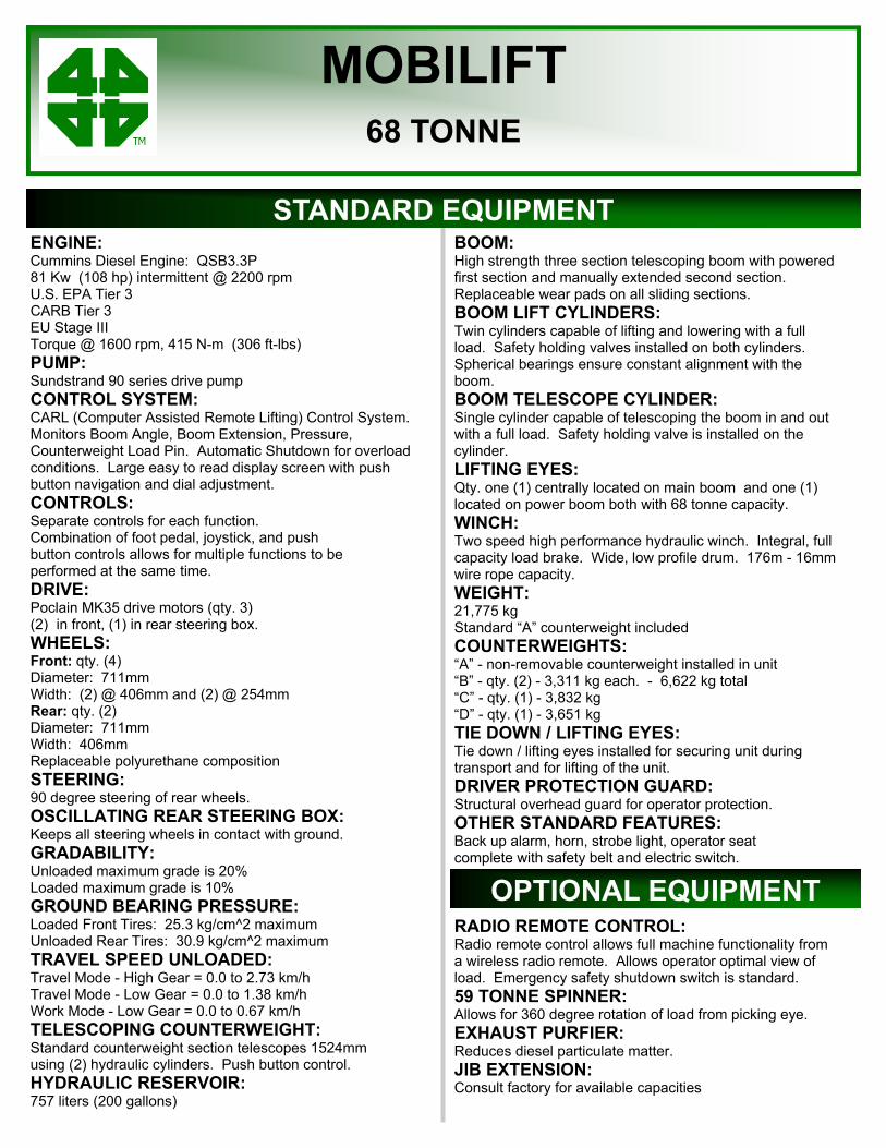
DIMENSIONAL DATA
MOBILIFT
68 TONNE
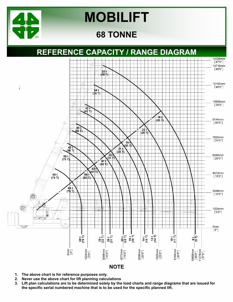
REFERENCE CAPACITY / RANGE DIAGRAM
NOTE 1. The above chart is for reference purposes only. 2. Never use the above chart for lift planning calculations 3. Lift plan calculations are to be determined solely by the load charts and range diagrams that are issued for
the specific serial numbered machine that is to be used for the specific planned lift.
MOBILIFT
68 TONNE
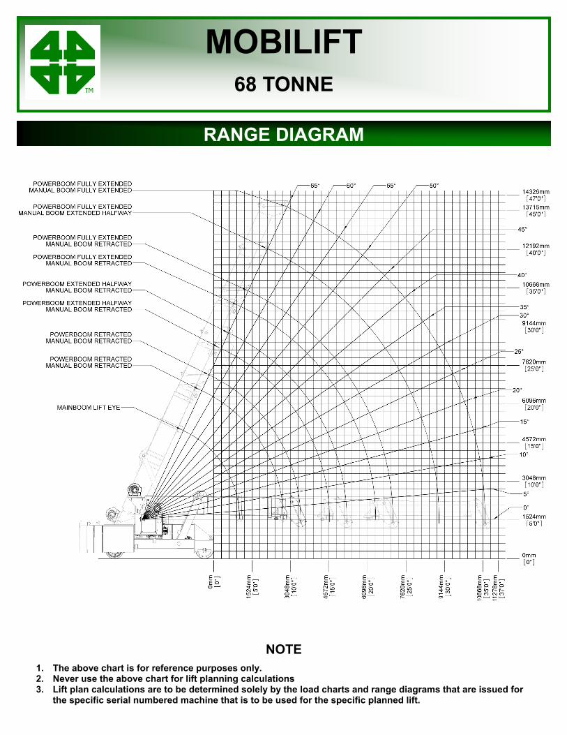
RANGE DIAGRAM
NOTE 1. The above chart is for reference purposes only. 2. Never use the above chart for lift planning calculations 3. Lift plan calculations are to be determined solely by the load charts and range diagrams that are issued for
the specific serial numbered machine that is to be used for the specific planned lift.
MOBILIFT
68 TONNE
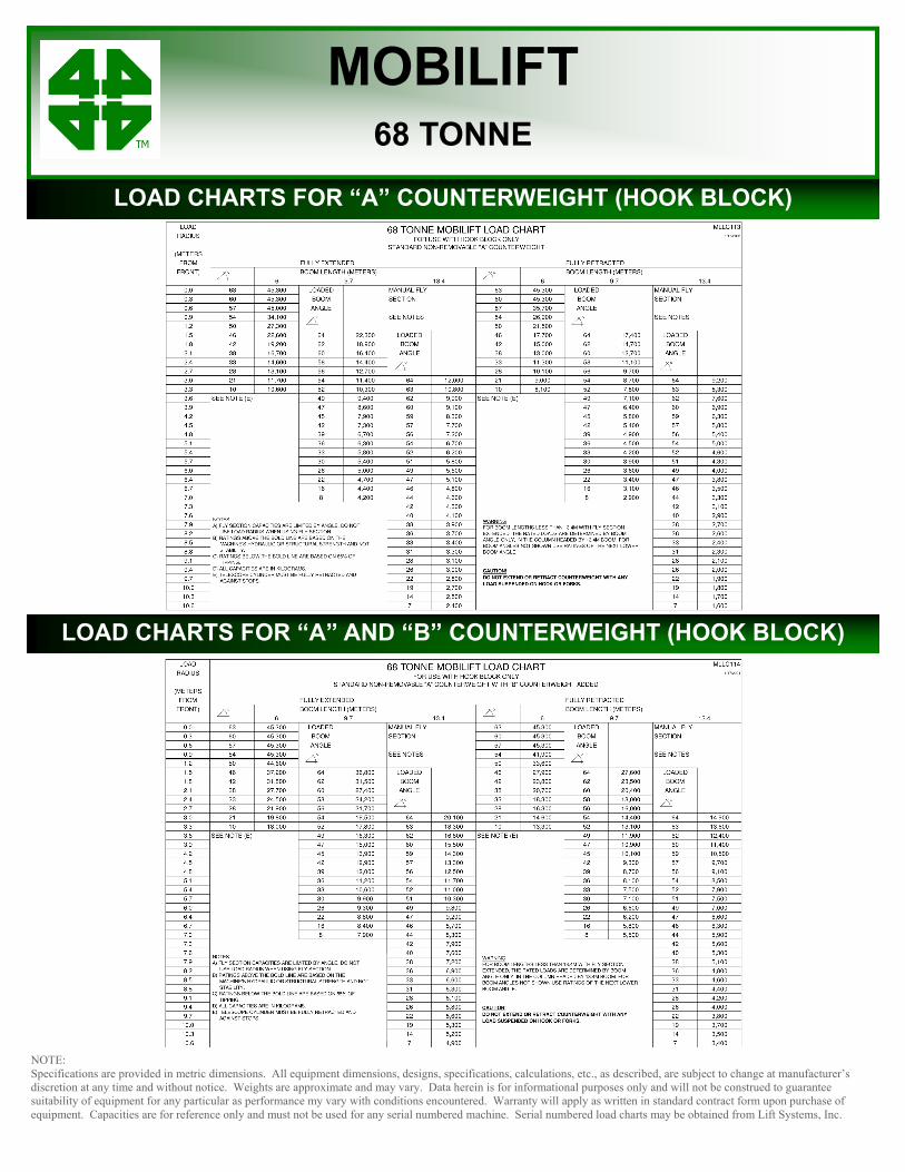
LOAD CHARTS FOR “A” COUNTERWEIGHT (HOOK BLOCK)
LOAD CHARTS FOR “A” AND “B” COUNTERWEIGHT (HOOK BLOCK)
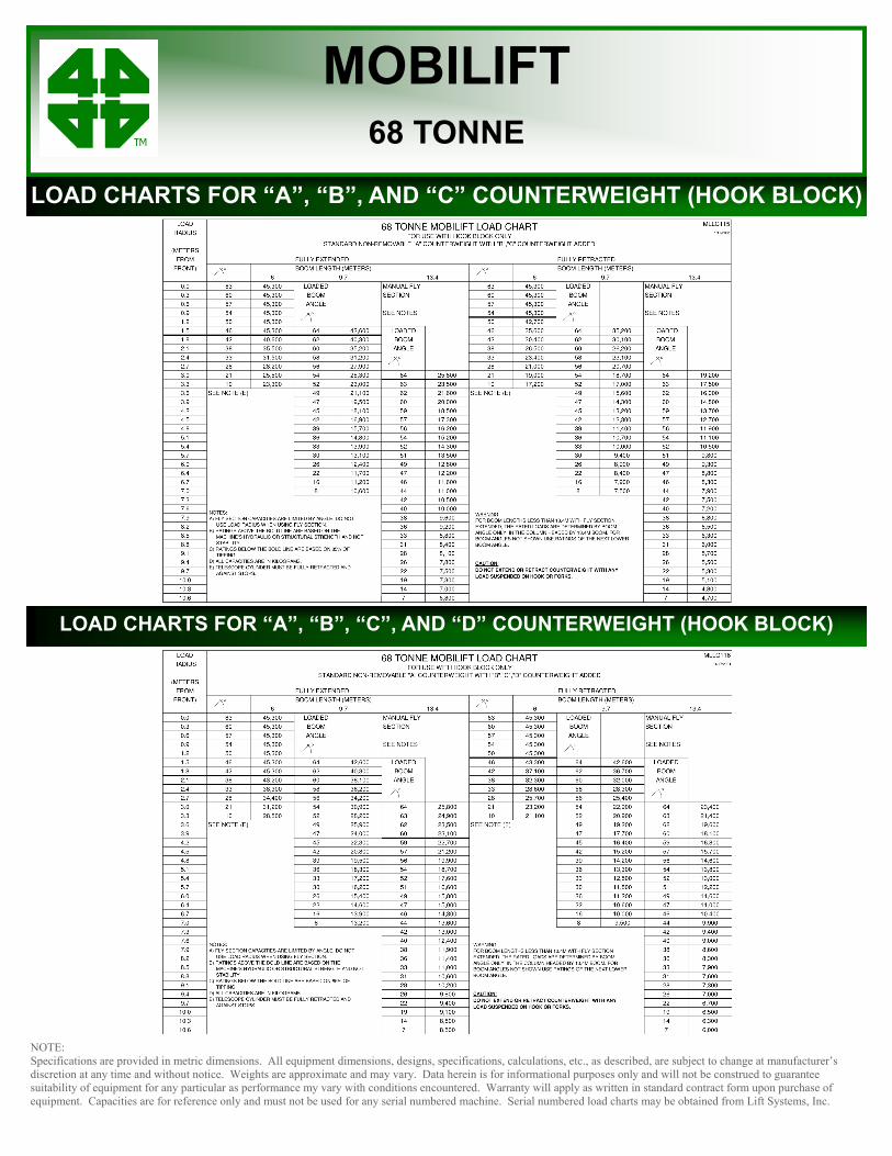
NOTE: Specifications are provided in metric dimensions. All equipment dimensions, designs, specifications, calculations, etc., as described, are subject to change at manufacturer’s discretion at any time and without notice. Weights are approximate and may vary. Data herein is for informational purposes only and will not be construed to guarantee suitability of equipment for any particular as performance my vary with conditions encountered. Warranty will apply as written in standard contract form upon purchase of equipment. Capacities are for reference only and must not be used for any serial numbered machine. Serial numbered load charts may be obtained from Lift Systems, Inc.
NOTE: Specifications are provided in metric dimensions. All equipment dimensions, designs, specifications, calculations, etc., as described, are subject to change at manufacturer’s discretion at any time and without notice. Weights are approximate and may vary. Data herein is for informational purposes only and will not be construed to guarantee suitability of equipment for any particular as performance my vary with conditions encountered. Warranty will apply as written in standard contract form upon purchase of equipment. Capacities are for reference only and must not be used for any serial numbered machine. Serial numbered load charts may be obtained from Lift Systems, Inc.
MOBILIFT
68 TONNE
LOAD CHARTS FOR “A” COUNTERWEIGHT (HOOK BLOCK)
LOAD CHARTS FOR “A” AND “B” COUNTERWEIGHT (HOOK BLOCK)
LOAD CHARTS FOR “A”, “B”, AND “C” COUNTERWEIGHT (HOOK BLOCK)
LOAD CHARTS FOR “A”, “B”, “C”, AND “D” COUNTERWEIGHT (HOOK BLOCK)
MOBILIFT
68 TONNE
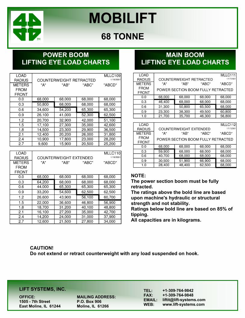
POWER BOOM LIFTING EYE LOAD CHARTS
LIFT SYSTEMS, INC.
OFFICE: MAILING ADDRESS: 1505 - 7th Street P.O. Box 906 East Moline, IL 61244 Moline, IL 61266
TEL: FAX: EMAIL: WEB:
+1-309-764-9842 +1-309-764-9848 [email protected] www.lift-systems.com
MAIN BOOM LIFTING EYE LOAD CHARTS
NOTE: The power section boom must be fully retracted. The ratings above the bold line are based upon machine's hydraulic or structural strength and not stability. Ratings below bold line are based on 85% of tipping. All capacities are in kilograms.
CAUTION! Do not extend or retract counterweight with any load suspended on hook.