Embed Size (px)
Citation preview

Life Safety Dampers• Fire • Combination Fire Smoke
• Smoke • Ceiling Radiation
June2018

2
Table of Contents
Introduction . . . . . . . . . . . . . . . . . . . . . . . . . . . . . . . . . . . . . . . . . 3-4
Fire Dampers . . . . . . . . . . . . . . . . . . . . . . . . . . . . . . . . . . . . . . . 5-19
Application . . . . . . . . . . . . . . . . . . . . . . . . . . . . . . . . . . . . . . . . . . . . . . . . . . . 5 UL Standards . . . . . . . . . . . . . . . . . . . . . . . . . . . . . . . . . . . . . . . . . . . . . . . . . 6 Installation Requirements . . . . . . . . . . . . . . . . . . . . . . . . . . . . . . . . . . . . . . . . . . 7-9 Special Installations . . . . . . . . . . . . . . . . . . . . . . . . . . . . . . . . . . . . . . . . . . . . . .10 Difference Between Curtain and Multi-Blade Fire Dampers. . . . . . . . . . . . . . . . . . . . . . . . 11-12 Accessories . . . . . . . . . . . . . . . . . . . . . . . . . . . . . . . . . . . . . . . . . . . . . . . . . .13 Selection and Sizing Charts . . . . . . . . . . . . . . . . . . . . . . . . . . . . . . . . . . . . . . . . 14-19
Smoke Dampers . . . . . . . . . . . . . . . . . . . . . . . . . . . . . . . . . . . . . 20-28
Application . . . . . . . . . . . . . . . . . . . . . . . . . . . . . . . . . . . . . . . . . . . . . . . . . . .20 UL Standards . . . . . . . . . . . . . . . . . . . . . . . . . . . . . . . . . . . . . . . . . . . . . . . . .21 Installation Requirements . . . . . . . . . . . . . . . . . . . . . . . . . . . . . . . . . . . . . . . . . . .22 Construction . . . . . . . . . . . . . . . . . . . . . . . . . . . . . . . . . . . . . . . . . . . . . . . . 23-24 Actuators. . . . . . . . . . . . . . . . . . . . . . . . . . . . . . . . . . . . . . . . . . . . . . . . . . 25-26 Selection and Sizing Charts . . . . . . . . . . . . . . . . . . . . . . . . . . . . . . . . . . . . . . . . 27-28
Combination Fire Smoke Dampers . . . . . . . . . . . . . . . . . . . . . . . . . . . 29-37
Application . . . . . . . . . . . . . . . . . . . . . . . . . . . . . . . . . . . . . . . . . . . . . . . . . . .29 Installation Requirements . . . . . . . . . . . . . . . . . . . . . . . . . . . . . . . . . . . . . . . . . 30-31 Construction . . . . . . . . . . . . . . . . . . . . . . . . . . . . . . . . . . . . . . . . . . . . . . . . 32-33 Actuators. . . . . . . . . . . . . . . . . . . . . . . . . . . . . . . . . . . . . . . . . . . . . . . . . . . .34 Closure Devices . . . . . . . . . . . . . . . . . . . . . . . . . . . . . . . . . . . . . . . . . . . . . . . .35 Selection and Sizing Charts . . . . . . . . . . . . . . . . . . . . . . . . . . . . . . . . . . . . . . . . 36-37
Round Dampers. . . . . . . . . . . . . . . . . . . . . . . . . . . . . . . . . . . . . . 38-39
Ceiling Radiation Dampers. . . . . . . . . . . . . . . . . . . . . . . . . . . . . . . . 40-43
Application . . . . . . . . . . . . . . . . . . . . . . . . . . . . . . . . . . . . . . . . . . . . . . . . . . .40 Non-Combustible Assemblies . . . . . . . . . . . . . . . . . . . . . . . . . . . . . . . . . . . . . . . . .40 Combustible Assemblies . . . . . . . . . . . . . . . . . . . . . . . . . . . . . . . . . . . . . . . . . . .41 Options and Selection Chart. . . . . . . . . . . . . . . . . . . . . . . . . . . . . . . . . . . . . . . . . .42
Performance (Pressure Drop) . . . . . . . . . . . . . . . . . . . . . . . . . . . . . . 43-47
Accessories . . . . . . . . . . . . . . . . . . . . . . . . . . . . . . . . . . . . . . . . 48-52
Factory Mounted Accessories . . . . . . . . . . . . . . . . . . . . . . . . . . . . . . . . . . . . . . . . .48 Testing Devices . . . . . . . . . . . . . . . . . . . . . . . . . . . . . . . . . . . . . . . . . . . . . . . .49 Blade Indicators and Smoke Detectors . . . . . . . . . . . . . . . . . . . . . . . . . . . . . . . . . . . .50 Transitions and installation. . . . . . . . . . . . . . . . . . . . . . . . . . . . . . . . . . . . . . . . . . .51 Convenience Features . . . . . . . . . . . . . . . . . . . . . . . . . . . . . . . . . . . . . . . . . . . . .52 Cost Saving Products . . . . . . . . . . . . . . . . . . . . . . . . . . . . . . . . . . . . . . . . . . . . .53
General Information . . . . . . . . . . . . . . . . . . . . . . . . . . . . . . . . . . . 54-59
Model Definition . . . . . . . . . . . . . . . . . . . . . . . . . . . . . . . . . . . . . . . . . . . . . . . .54 Drive Arrangement Definition . . . . . . . . . . . . . . . . . . . . . . . . . . . . . . . . . . . . . . . . .55 Specification Checklist . . . . . . . . . . . . . . . . . . . . . . . . . . . . . . . . . . . . . . . . . . . .56 Modifications to Life Safety Dampers . . . . . . . . . . . . . . . . . . . . . . . . . . . . . . . . . . . . .57 Most Commonly Asked Questions . . . . . . . . . . . . . . . . . . . . . . . . . . . . . . . . . . . . . .58 Inspection, Maintenance and Testing . . . . . . . . . . . . . . . . . . . . . . . . . . . . . . . . . . . . .59

3
Life Safety Dampers
Life safety dampers are intended to protect openings in walls, ceilings, floors and/or partitions to prevent the spread of fire and/or smoke. The four types are:
Fire Dampers
Smoke Dampers
Combination Fire Smoke Dampers
Ceiling Radiation Dampers
Fire Dampers are required by building codes to maintain the required fire resistance ratings of walls, partitions and floors when they are penetrated by air ducts and transfer openings. These products are tested and classified in accordance with UL Standard 555.
Smoke Dampers have two applications:
1. They may be applied in a passive smoke control system where they simply close and prevent the circulation of air and smoke through a duct or a ventilation opening in a smoke barrier.
2. They may be applied as part of an engineered smoke control system designed to control the spread of smoke using the building’s HVAC system and/or dedicated fans to create pressure differences.
These products are tested and classified in accordance with UL Standard 555S.
Combination Fire Smoke Dampers perform the function of both a fire damper and a smoke damper. These products are tested and classified in accordance with both UL 555 and UL 555S.
Ceiling Radiation Dampers are designed to protect penetrations through the ceiling membrane of fire resistive floor ceiling and/or roof ceiling assemblies. These products are tested and listed in accordance with UL Standard 555C and 263.
4
Codes and Standards
The terms “code” and “standard” are often used interchangeably but there is a fine point of difference. A code is a set of regulations and requirements written in appropriate language with the expectation that it will become law. A code is enacted into law when it is adopted by formal action of a governing body or other authority having jurisdiction.
A standard is not necessarily written with the expectation that it will be adopted by some authority having jurisdiction and become law. Rather, a standard is intended to establish a defined level of performance or requirements, and often includes a listing of the necessary tests and qualifications for compliance with the standard. Codes often reference standards making them a part of the referencing code. For example, the 2018 International Building Code references UL (Underwriters Laboratory Standard 555 as the appropriate standard for qualifying fire dampers for use under the International Building Code.
Compliance with the Applicable Building Codes is MandatoryIf a state, city, or other authority having jurisdiction has adopted one or more codes governing construction within that jurisdiction, these codes are the law and must be followed. As there are many code documents in existence that have not been adopted by every authority with jurisdiction, it is important that both the designer and contractor know exactly what codes are applicable to the building in question.
The intent of the International Building Code is to provide minimum requirements to safeguard the public health, safety, and general welfare of the occupants of new and existing buildings and structures (2018 IBC, page ix).
The subject of codes and standards cannot be treated in any depth in the space available in this manual. See installation instructions and installation supplements for specific information.
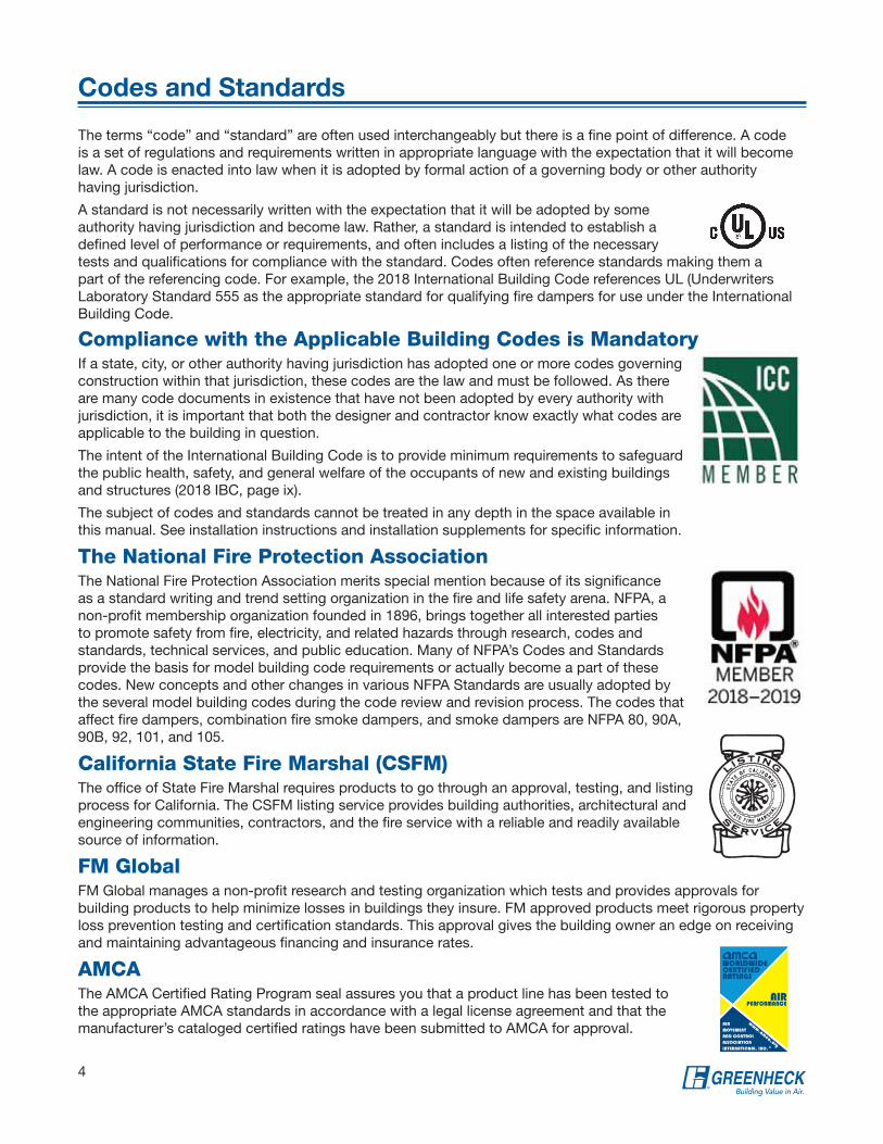
The National Fire Protection AssociationThe National Fire Protection Association merits special mention because of its significance as a standard writing and trend setting organization in the fire and life safety arena. NFPA, a non-profit membership organization founded in 1896, brings together all interested parties to promote safety from fire, electricity, and related hazards through research, codes and standards, technical services, and public education. Many of NFPA’s Codes and Standards provide the basis for model building code requirements or actually become a part of these codes. New concepts and other changes in various NFPA Standards are usually adopted by the several model building codes during the code review and revision process. The codes that affect fire dampers, combination fire smoke dampers, and smoke dampers are NFPA 80, 90A, 90B, 92, 101, and 105.
California State Fire Marshal (CSFM)The office of State Fire Marshal requires products to go through an approval, testing, and listing process for California. The CSFM listing service provides building authorities, architectural and engineering communities, contractors, and the fire service with a reliable and readily available source of information.
FM GlobalFM Global manages a non-profit research and testing organization which tests and provides approvals for building products to help minimize losses in buildings they insure. FM approved products meet rigorous property loss prevention testing and certification standards. This approval gives the building owner an edge on receiving and maintaining advantageous financing and insurance rates.
AMCAThe AMCA Certified Rating Program seal assures you that a product line has been tested to the appropriate AMCA standards in accordance with a legal license agreement and that the manufacturer’s cataloged certified ratings have been submitted to AMCA for approval.

Fire
Da
mp
ers
5
Fire Dampers
Fire rated partitions contain fire damage
to the compartment of fire origin.
Unprotected partition
Partition protected
by fire damper
Type of PenetrationMinimum Damper
Rating
Less than 3 hour fire resistance rated assemblies 1½ hours
3 hour or greater fire resistance rated assemblies
3 hours
Static vs. DynamicFire dampers carry a UL 555 rating and can be either STATIC or DYNAMIC rated.
Static rated fire dampers have no airflow closure rating and can only be applied in HVAC systems that are designed to shut down automatically in the event of a fire.
Dynamic rated fire dampers carry a UL 555 rating to close while the HVAC system is running. Dynamic rated fire dampers carry both an airflow velocity (ft/min) rating and a pressure differential rating (in. wg) and should be selected to operate against the conditions they will see in their application. Dynamic rated fire dampers are always an appropriate selection for either HVAC system.
Application Fire dampers are required by building codes to maintain the required fire resistance ratings of walls, partitions, barriers, and floors when they are penetrated by air ducts or other air transfer openings.
One of the basic requirements of building fire protection is the compartmentation, or dividing up of buildings using fire rated walls and floors. This compartmentation concept is intended to contain any fire to the compartment of origin and thereby minimize damage to property and protect the lives of people living and/or working in the building. A duct or ventilation opening in any of the fire rated partitions could permit a fire to spread from the compartment of origin to adjoining compartments. Fire dampers are installed in these duct or ventilation openings. They close automatically upon detection of heat by a heat-responsive device (usually by the melting of a fusible link), blocking the opening and preventing the spread of fire into the adjoining compartment.
Hourly Fire RatingWalls, floors, or partitions with a fire resistance rating of 3 hours or more require fire dampers with a 3 hour rating. Fire resistance ratings less than 3 hours require an 11⁄2 hour rated fire dampers.

Fir
e
Da
mp
ers
6
UL Standards for Testing and Rating of Fire Dampers
2400
2200
2000
1800
1600
1400
1200
1000
800
600
400
200
0
1315.6
1204.4
1093.3
962.2
871.1
760.0
648.8
537.8
426.7
315.6
204.4
93.3
-17.80 1 2 3 4 5 6 7 8
Hours
Deg
rees
Cel
sius
Time-Temperature Curve
Deg
rees
Fah
renh
eit
UL (Underwriters Laboratories) Classified fire dampers are tested to UL Standard 555 “Fire Dampers”. They are always supplied with an appropriate UL label. Below are some of the test requirements that UL 555 classified dampers are subjected to.
Fire Endurance Test and Hose Stream Test (UL 555)
Dampers are exposed to a standard fire test for a period of either 11⁄2 or 3 hours. This standard fire test is controlled to follow the time temperature curve illustrated. Immediately after the conclusion of the fire test, the dampers are subjected to a high pressure hose stream test. During the test a water pressure of 30 psi (207 kPa) for 11⁄2 hour dampers and 45 psi (310 kPa) for 3 hour dampers is applied at a distance of 20 feet (6 meters). The hose stream test provides an extreme shock that ensures the dampers are structurally strong enough to withstand the rigors of the most severe fire conditions.
Dynamic Closure Test (UL 555)
The UL 555 dynamic closure test evaluates the ability of a fire damper or combination fire smoke damper to close under airflow. The minimum velocity at which a dynamic closure rating can be issued is 2000 fpm. Extended ratings can be achieved in increments of 1000 fpm. As a safety factor to achieve a given rating, the damper is tested at 400 fpm above the desired rating. The damper is tested three times at ambient air conditions and then a fourth time with the air heated such that the damper’s temperature response device causes the damper to close.
Salt Spray Exposure Test (UL 555 & UL 555S)
A damper sample is exposed to salt spray in a test chamber for a period of 120 hours. After this exposure, the damper must close (and latch if a latch is provided). This test demonstrates a damper’s ability to function after a more severe fouling than the damper is likely to experience during its intended application.
Cycling Test (UL 555)
A non-actuated damper (gravity or spring force) must be cycled open and closed 250 times. An actuated damper must be cycled 20,000 times. A damper with an actuator that has previously been subjected to the Operational Reliability Cycle Test is exposed to an elevated temperature of 250°F (121°C) minimum (or higher in multiples of 100°F [38°C]) for a period of 30 minutes. After 30 minutes of exposure and while still at the elevated temperature, the damper actuator must operate the damper open and closed three times. Time of operation cannot exceed 75 seconds for any of the open or closed operations.
UL 555 requires closure devices to have a minimum temperature rating of 160°F (71°C). The maximum temperature rating is 212°F (100°C) for static rated dampers and 350°F (177°C) for dynamic rated dampers. In addition, the IBC states “The operating temperature shall be approximately 50°F (10°C) above the normal temperature within the duct system”.

Fire
Da
mp
ers
7
Installation
Clearances required between damper sleeves and
wall or floor openings
Clearance requirements are different between two sided and single side angle installation. (See Installing damper/sleeve assembly in wall and floor openings, page 9, for limitations).
Two-sided angle installations require clearances of: • For galvanized steel dampers: 1⁄8 in. (3mm) per
foot of damper width or height for galvanized steel dampers with a minimum of 1⁄4 in. (6mm) and a maximum of 11⁄2 inches (38mm).
• For stainless steel dampers: 3⁄16 in. (5mm) per foot of damper width or height with a minimum of 1⁄4 in. (6mm) and a maximum of 2 inches (51mm).
• On true round dampers, the wall/floor opening must be a minimum of 7⁄8 in. (22mm) larger than the outside diameter of the damper.
Vertical mount single side angle installation has no minimum clearance requirements. However, we recommend clearances between the wall opening and the sleeve to make installation easier. A horizontal mount installation requires clearances of 1⁄8 in. (3mm) per foot of damper width and height with a minimum clearance of 1⁄4 in. (6mm).
Mounting Orientation
Fire dampers are required to pass separate tests for vertical mount and horizontal mounting applications. Dampers need to be installed in the correct orientation to ensure life safety and proper fire protection. Every fire damper is supplied with a label identifying the required mounting orientation. These mounting
orientations are not interchangeable.
Vertical mount dampers must be installed in masonry, block, or stud walls. Horizontal mount dampers must be installed in concrete floors except when using the I503 horizontal non-concrete application (see Special Installations).
The IBC (International Building Code) requires life safety dampers to be installed in accordance with the manufacturer’s installation instructions and the damper’s listing.
UL requires all fire, smoke, and combination fire smoke damper manufacturers to publish specific damper installation instructions detailing the required installation methods and procedures to properly install each specific model of damper. These instructions must be followed to maintain the validity of the damper’s UL listing. A copy of the appropriate installation instruction(s) is included with each shipment of UL fire, smoke, or combination fire smoke dampers. Installation requirements may differ between damper manufacturers as a manufacturer may qualify alternate installation methods by conducting additional tests. Dampers must be installed in accordance with instructions published by the company that manufactured the dampers.
1/4 in. minimumtotal clearance
Maximum 6 in.
Maximum 6 in.
Wall or floor
Damper
Duct
Retaining AnglesSleeve(See Sleeve Requirements)
Type A
Horizontal Label
(curtain style)
Vertical Label
(curtain style)

Fir
e
Da
mp
ers
8
Installation
Typical Sleeve Length Requirements
Wall or Floor Thickness Inches (mm)
Sleeve Length Required Inches (mm)
4 - 6 (102 - 152)
16 - 21 (406 - 533)
7 - 10 (178 - 254)
21 - 24 (533 - 610)
11 - 13 (279 - 330)
24 - 28 (610 - 711)
Sleeve Length Equation
Lmin = A + B + T
Lmin = minimum sleeve length
A = length of sleeve beyond wall (actuator side or factory mounted access door)
B = length of sleeve beyond wall (on side without actuator or factory mounted access door)
T = wall thickness
Overall Sleeve Length
6 in.Max.
Actuator andaccessoriesare mountedin thisgeneral area
Damper
16 in. Max.*
*Actuator side or factory mounted access door
A BT
Wall Thickness
Sleeve Length Considerations
Lmin
TABLE 1: Minimum Sleeve Thicknesses for Fire/Combination Fire Smoke Dampers
Sleeve Gauge Duct DimensionType of Duct to Sleeve Connection Permitted
14 ga. (0.075 in.) - 10 ga. (0.138 in.)[2mm - 3.5mm]
All duct sizesRigid or
Breakaway
16 ga. (0.060 in.)[1.5mm]
36 in. (914mm) max. width24 in. (610mm) max. height
24 in. (610mm) diameterRigid or Breakaway
16 ga. (0.060 in.)[1.5mm]
All duct sizes
Breakaway only
18 ga. (0.048 in.)[1.2mm]
85 in. (2159mm) wide and over
20 ga. (0.036 in.)[0.9mm]
55 in. - 84 in. wide(1397mm - 2134mm)
22 ga. (.030 in.)[0.76mm]
31 in. - 54 in. wide(787mm - 1372mm)
24 ga. (0.024)[0.6mm]
13 in. - 30 in. wide(330mm - 762mm)
26 ga. (0.018 in.)[0.46mm]
12 in. wide and under(305mm)
Sleeve thickness must not be less than the gauge of the connecting duct.UL Standard 555 requires all ducts to terminate at fire damper sleeves.
Greenheck’s standard and most economical sleeve lengths are 16, 21, and 24 inches (406, 533, and 610mm)
Sleeve Requirements
All UL fire and combination fire smoke damper listings require that the damper be mounted in a sleeve of a required gauge and length prior to installation. A factory supplied sleeve ensures the correct gauge is used and the damper will be ready to install. If the sleeve is installed in the field, the installation instructions show you the method of attaching the sleeve and damper together. The sleeved damper is installed in the wall or floor opening and retained as part of the structure by angles attached to the sleeve. UL requires that connecting ducts terminate at each end of the damper sleeve.
Sleeve gauge requirements depend on the damper size and type of duct-to-sleeve connection used. Table 1 provides minimum fire and combination fire smoke damper sleeve thickness requirements as defined by UL 555.
Sleeves shall extend a maximum of 6 in. (152mm) beyond the wall or floor opening on each side. When a factory mounted access door is provided, the sleeve may extend a maximum of 16 in. (406mm) beyond the wall or floor opening on the access door side.

Fire
Da
mp
ers
9
Installation
Transverse Joints
Drive Slip Joint
Fire Damper Sleeve
3/8 in. bolts in corners between all angles
Neoprene or Butyl gasket between all angles
Duct
(Attach per manufacturer’s instructions)
Flanged system angles
6 in. long metal cleat or 1/16 in. maximum thickness plastic cleat; 12 in. c-c (minimum 1 per side)
Manufactured Flanged Systems
DuctSleeve
Typical TDC/TDF Joint
Installing damper/sleeve assembly in wall and floor
openings
With the exception of dampers that are specifically designed to be mounted outside the plane of the wall/floor opening (see special installation), the fire damper must be installed such that the centerline of the blades are mounted in the plane of the wall or floor. All fire dampers may utilize the two sided angle installation method. On 11⁄2 hour rated fire dampers, you may use the single side angle installation method up to the following maximum sizes:
• Vertical mount: 80 in. W x 50 in. H, 50 in. W x 80 in. H or 40 in. W x 100 in. H (2032mm x 1270mm, 1270mm x 2032mm, or 1016mm x 2540mm)
• Horizontal mount: 144 in. W x 96 in. H (3658mm x 2438mm)
Duct-to-sleeve connections
Dampers requiring duct-to-sleeve connection, UL allows a rigid or breakaway connection.
A rigid connection is, by UL’s definition, any connection that has not been qualified as a breakaway connection.
A number of qualified breakaway connections, as well as procedures for qualifying additional breakaway connections, are defined in UL Standard 555. All qualified breakaway connections must be described in the damper manufacturer’s fire and combination fire smoke damper installation instructions.
Examples of qualified breakaway connections are:
• Transverse joints on the top and bottom
• Drive slip joints on the sides
• Type R or O damper transitions
• Manufactured flanged systems manufactured by Ductmate, Durodyne, Ward, Nexus, Radiant T-35m, and MEZ
• Proprietary flange system: TDC by Lockformer and TDF by Engle
Wall or Floor
Maximum 6 in.
Maximum 6 in.
DuctDamper
Retaining Angles
Type A
1/4 in. minimumtotal clearance1/4 in. minimumtotal clearance

Fir
e
Da
mp
ers
10
Special Installation
Horizontal Fire Smoke Damper in a Non-Concrete BarrierFire rated shafts enclose the space extending through one or more stories of a building, connecting vertical openings in successive floors, or floors and roof. One of the more difficult tasks facing designers, contractors, and inspectors when working with a shaft that is penetrated by a duct, is protecting the horizontal opening at the top or bottom of the rated shaft. There are three typical methods used to enclose the bottom of the shaft when it does not extend to the top or bottom of the building or structure.
Method 1: Using a fire resistant rated construction
It is important to note that when a shaft is enclosed at the bottom with fire resistant rated construction, it is required that the assembly has passed the fire test in the horizontal position and any penetrations in the shaft be protected per applicable building codes. Duct penetrations can then be protected with vertically mounted fire smoke dampers.
Method 2: Terminate the shaft in a room
The shaft and room need to be separate from the remainder of the building with construction equal to the fire resistive rating of the shaft. Duct penetrations can then be protected with vertically mounted fire smoke dampers.
Method 3: Using a 2 hour fire rated floor/ceiling design (I503)
UL Fire Resistance Design Number I503 is the first UL listed floor/ceiling design made from steel studs and gypsum board that is approved with damper penetrations. Greenheck series DFD, FD and FSD dampers are approved to be used in this innovative design. This installation method results in more usable space for the owner, more flexibility for the design professional, and reduces installation time for the contractor.
What if a Damper Cannot be Installed in the Wall?
Greenheck has tested and qualified fire and combination fire smoke dampers for installation out of the plane of the wall (models OFD, ODFD, GFSD and OFSD). This damper series is primarily designed to allow ‘through the grille’ access to actuators and controls. Model OFSD and GFSD series dampers meet all requirements of UL 555 and UL 555S.
Single 3 Sided Retaining Angle
Greenheck has tested and qualified 3 sided retaining angle installation fire and combination fire smoke dampers mounted in masonry, block, metal or wood stud walls. A retaining angle is used on the top and sides of the damper. A retaining angle is not required on the bottom side of the damper. The damper shall rest directly on the wall opening.
Floor
Mechanical
Room
Shaft
Combination Fire
Smoke Damper
Grille(supplied by others)
Factory Supplied Thermal Blanket
7½ in. Max.
Damper
OFSD
Rated Wall
Ductwork
Floor
Retaining Angle
Fire
Da
mp
ers
11
Curtain Style Fire Dampers
Stainless SteelClosure Spring
‘K’ Side
Fusible Link (replaceable)165°F. standard (212°F. available)
HORIZONTAL MOUNT
VERTICAL MOUNT3-11/16 inch
H*
W*
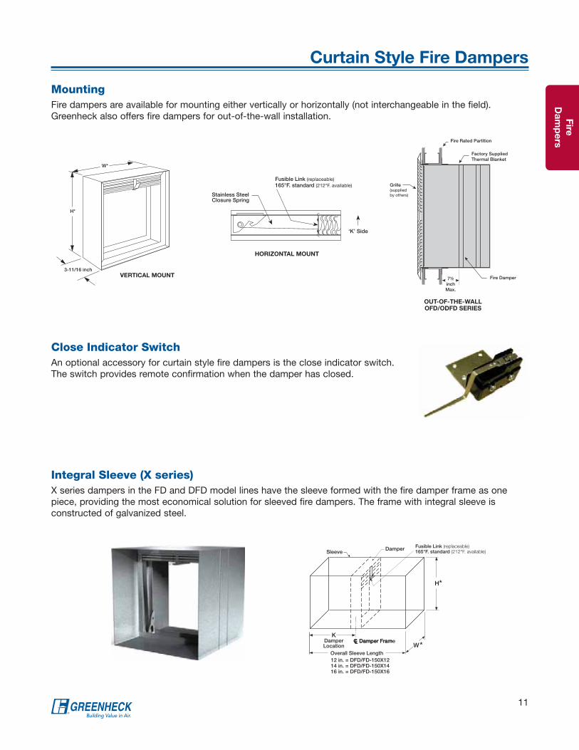
MountingFire dampers are available for mounting either vertically or horizontally (not interchangeable in the field). Greenheck also offers fire dampers for out-of-the-wall installation.
Close Indicator SwitchAn optional accessory for curtain style fire dampers is the close indicator switch. The switch provides remote confirmation when the damper has closed.
H*
KDamper Location W*
CL Damper Fram
Sleeve
CL Damper Frame
Damper
Overall Sleeve Length12 in. = DFD/FD-150X1214 in. = DFD/FD-150X1416 in. = DFD/FD-150X16
Fusible Link (replaceable)165°F. standard (212°F. available)
Fire Rated Partition
Factory Supplied Thermal Blanket
Fire Damper
Grille(supplied by others)
7½ inchMax.
Integral Sleeve (X series)X series dampers in the FD and DFD model lines have the sleeve formed with the fire damper frame as one piece, providing the most economical solution for sleeved fire dampers. The frame with integral sleeve is constructed of galvanized steel.
OUT-OF-THE-WALL OFD/ODFD SERIES

Fir
e
Da
mp
ers
12
Multi-Blade Fire Dampers
Variable Symmetric Blade Design (VSB) - a Greenheck Exclusive!• Blades are symmetric about their axis
• Combination of 4, 5, 6, and 7 in. (102, 127, 152, and 178mm) blade widths are used in a single damper
• Reduces the need for closure strips which optimize pressure drop performances
• Damper can be mounted in either direction of airflow
• Through extensive testing of our dampers, we have determined using various blade sizes reduces required actuator torque which reduces the size and quantity of actuators used on dampers. This reduces first costs for the building owner and on-going electrical power consumption.
ActuatorTorque
ActuatorTorque
Airflow worksagainstactuator
Airflow worksagainstactuator
Airflowworks with
actuator
Unbalanced BladeRequires Higher Torque
Balanced Blade Requires Less Torque
Maximize Performance - Low Profile FrameOn dampers that are 17 in. (432mm) high or less, Greenheck uses a low profile top and bottom frame to maximize free area, allowing for lower pressure drop and improved damper performance.
Tog-L-Loc®
Reinforced Corner
Frame - Tog-L-Loc® AdvantageGreenheck multi-blade fire dampers utilize a 5 in. x 1 in. (127mm x 25mm) hat channel frame. Each frame is built with four separate pieces of material and joined by our Tog-L-Loc® process. The Tog-L-Loc® process provides a more rigid frame that resists “racking” better than welded construction.
Manual
Quadrant
Frame
Linkage
Axle
Blade
MountingSingle section multi-blade fire dampers may be mounted vertically or horizontally as long as the blades stay horizontal. Multiple section multi-blade fire dampers must be mounted in the orientation in which they were ordered.

Fire
Da
mp
ers
13
Accessories
Factory Sleeve OptionFire dampers are available with factory-furnished sleeves. Sleeves are galvanized steel or stainless steel, depending on the model, and are available in gauges 10 through 20 (3 through 1 mm) thicknesses, and lengths up to 48 in. (1219mm).
Curtain Style Fire DampersThe “K” dimension specifies the location of the damper within the sleeve. Horizontal dampers must be installed with the “K” dimension on the top (K-side facing up).
Multi-Blade Fire DampersThe “A” dimension specifies the location of the damper within the sleeve.
H*
KDamper Location W*
CL Damper Fram
Sleeve
CL Damper Frame
Damper
Overall Sleeve Length
Fusible Link(replaceable)
Curtain Fire Damper in a Sleeve
ADamperLocation
L
CL Damper Frame
Sleeve
Damper
Multi-Blade Fire Damper in a Sleeve
TransitionsWhen a rectangular fire damper is being used in conjunction with round, square or oval ductwork, they can be supplied in a factory sleeve with round, square or oval transitions on one or both ends of the sleeve. Dampers should be ordered to the duct dimensions. For medium pressure ductwork, Greenheck can seal the transition and sleeve seams to prevent air leakage.
Type A Type B/B2 Type C Type CO Type CR Type R
Transitions for Curtain Style Fire Dampers
Transitions for Multi-Blade Style Fire Dampers
Type R Type O Type C
Horizontal Mount
“K” side
Stainless SteelClosure Spring
Fusible Link (replaceable)

Fir
e
Da
mp
ers
14
Quick Reference Guide
Accessories
Ret
aini
ng A
ngle
s
O
O
O
O
O
O
O
O
O
O
O
O
O
O
O
O
O
O
O
O
O
O
O
Closure Temperature
350°
F (
177°
C)
O
O
O
O
O
286°
F (
141°
C)
O
O
O
O
O
O
O
O
O
O
O
O
O
O
O
O
O
O
O
O
O
212°
F (
100°
C)
O
O
O
O
O
O
O
O
O
O
O
O
O
O
O
O
O
O
O
O
O
O
O
165°
F (
74°C
)
X
X
X
X
X
X
X
X
X
X
X
X
X
X
X
X
X
X
X
X
X
X
X
Fire Rating
3 H
our
X
X
X
X
X
X
X
X
1 ½
Ho
ur
X
X
X
X
X
X
X
X
X
X
X
X
X
X
X
Blade Profile
3V
X
X
X
Air
foil
X
X
Cur
tain
X
X
X
X
X
X
X
X
X
X
X
X
X
X
X
X
X
X
Material
316
Sta
inle
ss S
teel
X
304
Sta
inle
ss S
teel
X
X
X
X
X
Gal
vani
zed
Ste
el
X
X
X
X
X
X
X
X
X
X
X
X
X
X
X
X
X
Construction
5 in
. x 1
in. 1
6 g
a.(1
27 x
25
x 1.
5 m
m)
Hat
Cha
nnel
Fra
me
X
X
X
X
X
Sta
ndar
d F
ram
e 3
11/1
6 in
. (94
mm
)
X
X
X
X
X
X
X
X
X
X
Inte
gra
l S
leev
e 1
2, 1
4, 1
6 in
. le
ngth
(305
, 356
, 406
mm
)
X
X
Nar
row
line
Fra
me
2 3/
16 in
. (56
mm
)
X
X
X
X
Ultr
athi
n F
ram
e1
1/2
in. (
38 m
m)
X
X
X = StandardO = Optional
DFD-110
DFD-150
SSDFD-150
DFD-150X series
ODFD-150
DFD-210
DFDAF-310
DFDAF-330
SEDFD-210
SSDFD-210
DFD-310
DFD-350
SSDFD-350
FD-100
FD-110
FD-150
SSFD-150
FD-150X series
OFD-150
FD-300
FD-310
FD-350
SSFD-350
DFD/FD DFD/FD X Series DFD-210DFDAF-310/330

Fire
Da
mp
ers
15
Maximum Damper Size Limitations
Static Fire Dampers – Models and Sizes
Model
Mounting Horizontal or Vertical
(H or V)
Maximum Single Section Size W x H, in inches (mm) Maximum Multi section W x H, in inches (mm)*
No Transitionsor
A styleB/B2 C & CO CR
R
A B/B2 C & CO CR0 in. offset
1 in. offset
2 in. offset
11 ⁄2 H
our
FD-100 V48 x 48
(1219 x 1219)48 x 40
(1219 x 1016)--- --- --- ---
FD-110 H or V48 x 48
(1219 x 1219)48 x 42
(1219 x 1067)--- --- ---
96 x 48(2438 x 1219)
96 x 42(2438 x 1067)
---- ----
FD-150
H or V48 x 48
(1219 x 1219)48 x 42
(1219 x 1067)46 x 41
(1168 x 1041)41
(1041)30
(762)47
(1194)46
(1168)
96 x 48 or 120 x 40
(2438 x 1219 or
3048 x 1016)
96 x 42 or120 x 35
(2438 x 1067 or
3048 x 889)
94 x 41 or 118 x 34
(2438 x 1041 or
2997 x 864)
41(1041)
V37 x 37
(940 x 940)37 x 32
(940 x 813)37 x 31
(940 x 787)31
(787)30
(762)36
(914)35
(889)74 x 74
(1880 x 1880)74 x 69
(1880 x 1753)72 x 68
(1829 x 1727)68
(1727)
FD-150X12FD-150X14FD-150X16
H or V48 x 48
(1219 x 1219)48 x 42
(1219 x 1067)46 x 41
(1168 x 1041)41
(1041)30
(762)47
(1194)46
(1168)---
SSFD-150
V48 x 48
(1219 x 1219)48 x 42
(1219 x 1067)46 x 41
(1168 x 1041)41
(1041)30
(762)47
(1194)46
(1168)
96 x 48 or 120 x 40
(2438 x 1219 or
3048 x 1016)
96 x 42 or 120 x 35
(2438 x 1067or
3048 x 889)
94 x 41 or 118 x 34
(2438 x 1041 or
2997 x 864)
---
H36 x 36
(914 x 914)36 x 31
(914 x 787)34 x 30
(864 x 762)30
(762)30
(762)35
(889)34
(864)---
OFD-150 H or V36 x 36
(914 x 914)36 x 31
(914 x 787)--- --- --- ---
3 H
our
FD-300 V48 x 48
(1219 x 1219)48 x 40
(1219 x 1016)--- --- --- --- --- ---
FD-310 V48 x 48
(121 9 x 1219)48 x 42
(1219 x 1067)--- --- --- --- --- ---
FD-350
V48 x 48
(1219 x 1219)48 x 42
(1219 x 1067)46 x 41
(1168 x 1041)41
(1041)30
(762)47
(1194)46
(1168)---
H40 x 40
(1016 x 1016)40 x 35
(1016 x 889)38 x 34
(965 x 864)34
(864)30
(762)39
(991)38
(965)80 x 40
(2032 x 1016)80 x 35
(2032 x 889)78 x 34
(1981 x 964)---
SSFD-350 V48 x 48
(1219 x 1219)48 x 42
(1219 x 1067)46 x 41
(1168 x 1041)41
(1041)30
(762)47
(1194)46
(1168)---
*Multiple section sizeNote: For round fire dampers, see page 39.
The maximum size opening that can be protected by any manufacturer’s fire damper is specifically stated in the manufacturer’s UL Listing. These listings, which can be found on UL’s website (www.ul.com) under the category EMME, provide both the maximum single section size and the maximum multiple section size of a damper model. If no multiple section size is listed, the damper is limited strictly to single section applications.
The maximum damper sizes found in the UL Listings are based on tests conducted in accordance with UL Standard 555 (fire dampers). Filling openings larger than the maximum tested damper size is not approved by UL unless the opening requires only a static rated fire damper. Oversized openings in dynamic systems cannot be divided into smaller sections using support mullions. As always, the authority having jurisdiction can decide whether or not to approve an installation.

Fir
e
Da
mp
ers
16
Maximum Damper Size Limitations
Model
MountingHorizontal or Vertical
(H or V)
Maximum Maximum Size W x H, in inches (mm)
Temperature°F (°C)
Velocityft/min. (m/s)
Pressurein. wg (kPa)
No Transitions or A style
B/B2 C & CO CR
R
SingleSection
Multi section0 in.
offset1 in.
offset2 in.
offset
DFD-110
V
165° (74°)
2000(10)
4(1)
36 x 36(914 x 914)
72 x 48 (1829 x 1219)
72 x 45(1829 x 1143)
--- --- ---
3000(15.2)
30 x 30(762 x 762)
---30 x 26
(762 x 660)
4000(20)
24 x 24 or18 x 30
(610 x 610 or457 x 762)
---
24 x 21 or18 x 26
(610 x 533 or 457 x 660)
H2000(10)
30 x 30(762 x 762)
48 x 36 (1219 x 914)
48 x 33(1219 x 838)
V
212° (100°)
2000(10)
24 x 24(610 x 610)
48 x 36 or18 x 48
(1219 x 914 or 457 x 1219)
48 x 31 or18 x 45
(1219 x 787 or 457 x 1143)
3000 or 4000(15.2 or 20)
18 x 30(457 x 762)
---18 x 26
(457 x 660)
H2000(10)
24 x 24(610 x 610)
48 x 36 (1219 x 914)
48 x 33(1219 x 838)
V
286° (141°)
2000(10)
24 x 24(610 x 610)
18 x 48 (457 x 1219)
18 x 45(457 x 1143)
3000 or 4000(15.2 or 20)
18 x 30(457 x 762)
---18 x 26
(457 x 660)
H2000(10)
24 x 24(610 x 610)
---24 x 21
(610 x 533)
DFD-150
V
165° (74°)
2000(10)
4(1)
36 x 36(914 x 914)
72 x 48, 60 x 60 or 120 x 30
(1829 x 1219, 1524 x 1524 or
3048 x 762)
72 x 45, 60 x 58 or 120 x 26
(1829 x 1143, 1524 x 1422 or
3048 x 660)
70 x 44, 58 x 55or 118 x 25
(1778 x 1118, 1473 x 1397 or
2997 x 635)
55(1397)
30(762)
59(1499)
58(1473)
3000(15.2)
30 x 30(762 x 762)
---30 x 26
(762 x 660)28 x 25
(711 x 635)25
(635)30
(762)29
(737)28
(711)
4000(20)
24 x 24 or18 x 30
(610 x 610 or457 x 762)
---
24 x 21 or18 x 26
(610 x 533 or457 x 660)
22 x 20 or16 x 25
(559 x 508 or 406 x 635)
20(508)
24(610)
23(584)
22(559)
H2000(10)
30 x 30(762 x 762)
48 x 36(1219 x 914)
48 x 33(1219 x 838)
46 x 32(1168 x 813)
32(813)
30(762)
35(889)
34(864)
V
212° (100°)
2000(10)
24 x 24 or18 x 30
(610 x 610 or457 x 762)
48 x 36 or18 x 60
(1219 x 914457 x 1524)
48 x 31 or 18 x 56
(1219 x 787 or457 x 1422)
46 x 30 or16 x 55
(1168 x 762 or 406 x 1397)
30(762)
30(762)
35(889)
34(864)
3000 or 4000(15.2 or 20)
18 x 30(457 x 762)
---18 x 26
(457 x 660)16 x 25
(406 x 635)16
(406)18
(457)17
(432)16
(406)
H2000(10)
24 x 24(610 x 610)
48 x 36(1219 x 914)
48 x 33(1219 x 838)
46 x 32(1168 x 813)
32(813)
30(762)
35(889)
34(864)
V
286° (141°)
2000(10)
24 x 24 or18 x 30
(610 x 610 or457 x 762)
18 x 60(457 x 1524)
24 x 21 or 18 x 56
(610 x 533 or 457 x 1422)
22 x 20 or 16 x 55
(559 x 508 or406 x 1397)
20(508)
24(610)
23(584)
22(559)
3000 or 4000(15.2 or 20)
18 x 30(457 x 762)
---18 x 26
(457 x 660)16 x 25
(406 x 635)16
(406)18
(457)17
(432)16
(406)
H2000(10)
24 x 24(610 x 610)
---24 x 21
(610 x 533)22 x 20
(559 x 508)20
(508)24
(610)23
(584)22
(559)
Dynamic Fire Dampers (1½ Hour) – Models and Sizes

Fire
Da
mp
ers
17
Maximum Damper Size Limitations
Model
MountingHorizontal or Vertical
(H or V)
Maximum Maximum Size W x H, in inches (mm)
Temperature°F (°C)
Velocityft/min. (m/s)
Pressurein. wg (kPa)
No Transitions or A style
B/B2 C & CO CR
R
SingleSection
Multi section0 in.
offset1 in.
offset2 in.
offset
DFD-150X12DFD-150X14DFD-150X16
V
165° (74°)
2000(10)
4(1)
36 x 36(914 x 914)
---36 x 31
(914 x 787)34 x 30
(864 x 762)30
(762)30
(762)35
(889)34
(864)
3000(15.2)
30 x 30(762 x 762)
---30 x 26
(762 x 660)28 x 25
(762 x 635)25
(635)30
(762)29
(737)28
(711)
4000(20)
24 x 24(610 x 610)
---
24 x 21 or18 x 26
(610 x 533 or 457 x 660)
22 x 20 or16 x 25
(559 x 508 or406 x 635)
22(559)
24(610)
23(584)
22(559)
H2000(10)
30 x 30(762 x 762)
---30 x 26
(762 x 660)28 x 25
(711 x 635)25
(635)30
(762)29
(737)28
(711)
V
212° (100°)
2000(10)
24 x 24(610 x 610)
---
24 x 21 or18 x 26
(610 x 533 or 457 x 660)
22 x 20 or16 x 25
(559 x 508 or406 x 635)
22(559)
24(610)
23(584)
22(559)
3000 or 4000(15.2 or 20)
18 x 30(457 x 762)
---18 x 26
(457 x 660)16 x 25
(406 x 635)16
(406)18
(457)17
(432)16
(406)
H2000(10)
24 x 24(610 x 610)
---24 x 21
(610 x 533)22 x 20
(559 x 508)22
(559)24
(610)23
(584)22
(559)
V
286° (141°)
2000(10)
24 x 24(610 x 610)
---
24 x 21 or18 x 26
(610 x 533 or 457 x 660)
22 x 20 or16 x 25
(559 x 508 or406 x 635)
22(559)
24 (610)
23(584)
22(559)
3000 or 4000(15.2 or 20)
18 x 30(457 x 762)
---18 x 26
(457 x 660)16 x 25
(406 x 635)16
(406)18
(457)17
(432)16
(406)
H2000(10)
24 x 24(610 x 610)
---24 x 21
(610 x 533)22 x 20
(559 x 508)22
(559)24
(610)23
(584)22
(559)
ODFD-150
V
165° (74°)
2000(10)
4(1)
36 x 36(914 x 914)
---36 x 31
(914 x 787)---
3000(15.2)
30 x 30(762 x 762)
---30 x 26
(762 x 660)---
4000(20)
24 x 24 or18 x 30
(610 x 610 or457 x 762)
---
24 x 21 or18 x 26
(610 x 533 or(457 x 660)
---
H2000(10)
30 x 30(762 x 762)
36 x 36(914 x 914)
36 x 31(914 x 787)
---
V
212° (100°)
2000(10)
24 x 24 or18 x 30
(610 x 610 or457 x 762)
36 x 36(914 x 914)
36 x 31(914 x 787)
---
3000 or 4000(15.2 or 20)
18 x 30(457 x 762)
---18 x 26
(457 x 660)---
H2000(10)
24 x 24(610 x 610)
36 x 36(914 x 914)
36 x 31(914 x 787)
---
V
286° (141°)
2000(10)
24 x 24 or18 x 30
(610 x 610 or457 x 762)
36 x 36(914 x 914)
36 x 31(914 x 787)
---
3000 or 4000(15.2 or 20)
18 x 30(457 x 762)
---18 x 26
(457 x 660)---
H2000(10)
24 x 24(610 x 610)
---24 x 21
(610 x 533)---
SSDFD-150 V
Up to 212° (100°) 2000
(10)4
(1)
30 x 30 (762 x 762)
---30 x 26
(762 x 660)28 x 25
(711 x 635)25
(635)30
(762)29
(737)28
(711)
286° (141°)24 x 24
(610 x 610)---
24 x 21(610 x 533)
22 x 20(559 x 508)
20(508)
24(610)
23(584)
22(559)
Dynamic Fire Dampers (1½ Hour) – Models and Sizes

Fir
e
Da
mp
ers
18
Maximum Damper Size Limitations
Model
MountingHorizontalor Vertical
(H or V)
Maximum Maximum Size W x H, in inches (mm)
Temperature°F (°C)
Velocityft/min. (m/s)
Pressurein. wg(kPa)
No Transitions or A style
B/B2 C & CO CR
R
Single Section
Multi section0 in.
offset1 in.
offset2 in.
offset
DFD-310
V
165° (74°)
2000(10)
4(1)
36 x 36(914 x 914)
48 x 48(1219 x 1219)
48 x 45(1219 x 1143)
--- --- ---
3000(15.2)
4(1)
30 x 30(762 x 762)
---30 x 26
(762 x 660)
4000(20)
4(1)
24 x 24 or 18 x 30
(610 x 610 or457 x 762)
---
24 x 21 or18 x 26
(610 x 533 or457 x 660)
H2000(10)
4(1)
30 x 30(762 x 762)
40 x 36(1016 x 914)
40 x 33(1016 x 838)
V
212° (100°)
2000(10)
4(1)
24 x 24(610 x 610)
48 x 36 or18 x 48
(1219 x 914 or 457 x 1219)
48 x 31 or18 x 45
(1219 x 787 or457 x 1143)
3000 or 4000 (15.2 or 20)
4(1)
18 x 30(457 x 762)
---18 x 26
(457 x 660)
H2000(10)
4(1)
24 x 24 or 18 x 30
(610 x 610 or457 x 762)
40 x 36(1016 x 914)
40 x 33(1016 x 838)
V
286° (141°)
2000(10)
4(1)
24 x 24(610 x 610)
18 x 48(457 x 12190
18 x 45(457 x 1143)
3000 or 4000 (15.2 or 20)
4(1)
18 x 30(457 x 762)
---18 x 26
(457 x 660)
H2000(10)
4(1)
24 x 24(610 x 610)
---
24 x 21 or18 x 26
(610 x 533 or457 x 660)
DFD-350
V
165° (74°)
2000(10)
4(1)
36 x 36(914 x 914)
48 x 48(1219 x 1219)
48 x 45(1219 x 1143)
46 x 44(1168 x 1118)
44(1118)
30(762)
47(1194)
46(1168)
3000(15.2)
4(1)
30 x 30(762 x 762)
---30 x 26
(762 x 660)28 x 25
(711 x 635)25
(635)30
(762)29
(737)28
(711)
4000(20)
4(1)
24 x 24 or 18 x 30
(610 x 610 or 457 x 762)
---
24 x 21 or18 x 26
(610 x 533 or 457 x 660)
22 x 20 or 16 x 25
(559 x 508 or 406 x 635)
20 (508)
24(610)
23(584)
22(559)
H2000(10)
4(1)
30 x 30(762 x 762)
40 x 36(1016 x 914)
40 x 33(1016 x 914)
38 x 32(965 x 813)
32(813)
30(762)
35(889)
34(864)
V
212° (100°)
2000(10)
4(1)
24 x 24(610 x 610)
48 x 36 or 18 x 48
(1219 x 914 or457 x 1219)
48 x 31 or18 x 45
(1219 x 787 or 457 x 1143)
46 x 30 or16 x 44
(1168 x 762 or406 x 1118)
30(762)
30(762)
35(889)
34(864)
3000 or 4000(15.2 or 20)
4(1)
18 x 30(457 x 762)
---18 x 26
(457 x 660)16 x 25
(406 x 635)16
(406)18
(457)17
(432)16
(406)
H2000(10)
4(1)
30 x 30(762 x 762)
40 x 36(1016 x 914)
40 x 33(1016 x 914)
38 x 32(965 x 813)
32(813)
30(762)
35(889)
34(864)
V
286° (141°)
2000(10)
4(1)
24 x 24(610 x 610)
18 x 48(457 x 1219)
24 x 21 or18 x 45
(610 x 533 or457 x 1143)
22 x 20 or16 x 44
(559 x 508 or406 x 1118)
20(508)
24(610)
23(584)
22(559)
3000 or 4000(15.2 or 20)
4(1)
18 x 30(457 x 762)
---18 x 26
(457 x 660)16 x 25
(406 x 635)16
(406)18
(457)17
(432)16
(406)
H2000(10)
4(1)
24 x 24(610 x 610)
---24 x 21
(610 x 533)22 x 20
(559 x 508)20
(508)24
(610)23
(584)22
(559)
SSDFD-350 V
up to 212° (100°) 2000
(10)4
(1)
30 x 30(762 x 762)
---30 x 26
(762 x 660)28 x 25
(711 x 635)25
(635)30
(762)29
(737)28
(711)
286° (141°)24 x 24
(610 x 610)---
24 x 21(610 x 533)
22 x 20(559 x 508)
20(508)
24(610)
23(584)
22(559)
Dynamic Fire Dampers (3 Hour) – Models and Sizes

Fire
Da
mp
ers
19
Maximum Damper Size Limitations
Multi-Blade Dynamic Fire Dampers – Models and Sizes
Model
Mounting Horizontalor Vertical
(H or V)
Maximum Maximum Sizes H or V Installation, in inches (mm)
Temperature°F (°C)
Velocityft/min. (m/s)
Pressurein. wg (kPa)
No Transitions
C & O
R
Single Section Size Multi section0 in.
offset1 in.
offset2 in.
offset
1½ H
our
DFD-210
H
Up to286° (141°)
2000(10)
4(1)
32 x 50 (813 x 1270)
128 x 96(3251 x 2438)
C: 92 x 82(2337 x 2083)
O: 92 x 80(2337 x 2032)
30(762)
83(2108)
82(2083)
Up to 350° (177°)
36 x 36(914 x 914)
---34 x 34
(864 x 864)30
(762)35
(889)34
(864)
V
Up to286° (141°)
32 x 50 (813 x 1270)
128 x 100(3251 x 2540)
C: 92 x 82(2337 x 2083)
O: 92 x 80(2337 x 2032)
30(762)
83(2108)
82(2083)
Up to 350° (177°)
36 x 36(914 x 914)
---34 x 34
(864 x 864)30
(762)35
(889)34
(864)
H or V
Up to 212° (100°) 10
(2.5)
32 x 50(813 x 1270)
64 x 50 (1626 x 1270)
62 x 48 (1575 x 1219)
30(762)
49(1245)
48(1219)
Up to 350° (177°)
36 x 36(914 x 914)
---34 x 34
(864 x 864)30
(762)35
(889)34
(864)
Up to 212° (100°)
4000(20)
10(2.5)
32 x 50(813 x 1270)
---30 x 48
(762 x 1219)30
(762)31
(787)30
(762)
SEDFD-210 H or VUp to
350° (177°)2000(10)
4(1)
24 x 30(610 x 762)
48 x 30(1219 x 762)
46 x 28(1168 x 711)
30 (762)
29(737)
28(711)
DFDAF-310
HUp to
350° (177°)
2000(10)
4(1)
32 x 50(813 x 1219)
144 x 96(3658 x 2438)
C: 92 x 82(2337 x 2083)
O: 92 x 80(2337 x 2032)
30 (762)
83 (2108)
82(2083)
V
Up to286° (141°)
32 x 50(813 x 1219)
128 x 100(3251 x 2540)
C: 92 x 82(2337 x 2083)
O: 92 x 80(2337 x 2032)
30 (762)
83(2108)
82(2083)
Up to 350° (177°)
32 x 50(813 x 1219)
96 x 50(2438 x 1219)
92 x 48(2337 x 1219)
30 (762)
49(1245)
48(1219)
H or VUp to
350° (177°)4000(20)
8(2)
32 x 50(813 x 1219)
---30 x 48
(762 x 1219)30
(762)31
(787)30
(762)
3 H
our
DFDAF-330
V
Up to286° (141°)
2000(10)
4(1)
32 x 36 or 30 x 48(813 x 914 or 762 x 1219)
120 x 96(3048 x 2438)
C: 92 x 82(2337 x 2083)
O: 92 x 80(2337 x 2032)
30 (762)
83 (2108)
82(2083)
Up to 350° (177°)
32 x 36 or 30 x 48(813 x 914 or 762 x 1219)
32 x 48(813 x 1219)
30 x 46(762 x 1219)
30(762)
31(787)
30(762)
H
Up to286° (141°)
30 x 48(762 x 1219)
144 x 96(3658 x 2438)
C: 92 x 82(2337 x 2083)
O: 92 x 80(2337 x 2032)
30 (762)
83(2108)
82(2083)
Up to 350° (177°)
30 x 48(762 x 1219)
32 x 48 (813 x 1219)
30 x 46 (762 x 1168)
30 (762)
31 (787)
30 (762)
H or VUp to
350° (177°)4000 (20)
8 (2)
30 x 48 (762 x 1219)
--28 x 46
(711 x 1168)30
(762)29
(737)28
(711)

Sm
ok
e
Da
mp
ers
20
Smoke Dampers
ApplicationSmoke dampers are required to close and resist the passage of smoke through ducts or air transfer openings in smoke barriers.
Smoke dampers have two general applications. They may be applied in a “Passive Smoke Control System” where they simply close to minimize the passage of smoke through a duct or ventilation opening in a smoke barrier. They also may be applied as part of an “Engineered Smoke Control System” designed to control the spread of smoke using the building’s HVAC system and/or dedicated fans to create pressure differences. Higher pressures surround the fire zone and prevent the spread of smoke from the fire zone into other areas of the building. Smoke dampers are also used in air handling equipment for isolation.
Smoke dampers are motorized with electric or pneumatic actuators and are controlled by a smoke detector or a smoke control system to accomplish the intent of the design.
UL Classified smoke dampers are tested to UL Standard 555S “Smoke Dampers”. It is necessary to determine the following ratings when applying a UL smoke damper:
• Leakage: Class I (lowest leakage), Class II, or Class III (highest leakage). The 2015 International Building Code (IBC), section 717.3.2 requires a minimum of Leakage Class II. Leakage Class I is recommended to provide the safest level of protection.
• Elevated Temperature: 250°F or 350°F (121°C or 177°C) is the temperature at which the actuator must be able to operate the damper and the temperature at which the leakage test is conducted. Most often 350°F (177°C) is selected for the highest level of safety.
• Velocity and Pressure: UL 555S requires each smoke damper with its installed actuator to be rated for operation to open against a specific pressure differential (in. wg) and to close against a specific velocity of airflow (ft/min). Dampers should be selected to operate at the pressures and velocities they will be exposed to in their application, with a minimum of 4 in. wg (1 kPa) and 2000 ft/min (10.2 m/s).
SupplyFan
Return/Exhaust
Fan
Damper positioned to create positive pressurization
Typical Fire Smoke Zone
Typical Non-Smoke Zone
Damper positioned to create negative pressurization
Typical Engineered Smoke Control System
Smoke is contained to the fire zone by higherpressures in adjacent zones
Ret
urn/
Exh
aust
Air
Sup
ply
Air
Typical Smoke Damper

Sm
ok
e
Da
mp
ers
21
UL Standards for Testing and Rating of Smoke Dampers
Leakage Class
Maximum Leakage in cfm/ft2 Maximum Leakage in cmh/m2
@ 4 in. wg @ 8 in. wg @ 1 kPa @ 2 kPa
Class I 8 11 146 201
Class II 20 28 366 512
Class III 80 112 1463 2048
UL (Underwriters Laboratories) Classified smoke dampers are tested to UL Standard 555S “Smoke Dampers”. They are always supplied with an appropriate UL label. Below are some of the test requirements that UL 555S classified dampers are subject to.
Cycle Test (UL 555S)UL classified smoke dampers are cycled open and closed (by their actuator) 20,000 times. Smoke dampers that are also intended for use as a volume control damper must be cycled open and closed 100,000 repositioning cycles. These cycling tests are performed prior to all other tests (described below) and ensure that the damper will function reliably after repeated operations.
Salt Spray Exposure Test (UL 555 & UL 555S)A damper sample is exposed to salt spray in a test chamber for a period of 120 hours. After this exposure, the damper must close (and latch if a latch is provided). The purpose of this test is to make sure the damper operates after build-up.
Operational Test (UL 555S)During an operation test a smoke damper and actuator assembly must demonstrate the ability to operate under the velocity and pressure conditions for which it is rated. The assembly must cycle three times under ambient conditions and then one time after being exposed to the rated temperature (250°F or 350°F) for 15 minutes.
Temperature Degradation Test (UL 555S)A damper with an actuator that has previously been subjected to the Operational Test (described above) is exposed to an elevated temperature of 250°F (121°C) minimum (or higher in multiples of 100°F [38°C]) for a period of 30 minutes. After 30 minutes exposure and while still at the elevated temperature, the damper actuator must operate the damper open and closed three times. Time of operation cannot exceed 75 seconds for any of the open or closed operations.
Leakage Test (UL 555S)At least three damper sizes of each model being tested (minimum width by maximum height, maximum width by minimum height, and maximum width by maximum height) that have previously been subjected to both the Cycle Test and the Temperature Degradation Test must be tested for leakage. The minimum airflow and pressure ratings of dampers shall be 2000 ft/min (10.2 m/s) and 4 in. wg. (1 kPa). Ratings shall be set in 1000 ft/ min (5 m/s) increments from the minimum airflow and in 2 in. wg (0.5 kPa) increments from the minimum pressure. A damper’s leakage rating is based on the worst-case performance of the three damper sizes tested.

Sm
ok
e
Da
mp
ers
22
Installation
24 in.maximum
Ductwork
Duct Outlet
SmokeBarrier
Sealant
Damper
The IBC (International Building Code) requires life safety dampers to be installed in accordance with the manufacturer’s installation instructions and the damper’s listing.
UL (Underwriters Laboratories) requires all fire, smoke, and combination fire smoke damper manufacturers to publish specific damper installation instructions detailing the required installation methods and procedures to properly install each specific model of damper. These instructions must be followed to maintain the validity of the damper’s UL listing. A copy of the appropriate installation instruction(s) is included with each shipment of UL fire, smoke, or combination fire smoke dampers. Installation requirements may differ between damper manufacturers as a manufacturer may qualify alternate installation methods by conducting additional tests. Dampers must be installed in accordance with instructions published by the company that manufactured the dampers.
Location of DamperThe centerline of the damper blades must be within 24 in. (610mm) of the rated smoke barrier and before any duct inlets or outlets.
Attaching Damper to the DuctAttach the damper to the duct using sheet metal screws, bolts and nuts, tack or spot weld, or pop rivets. Attachments must be made per installation instructions to sleeve or sideplate.
Sealing the Damper Frame to the DuctworkAfter installing the damper, seal the joint between the damper and ductwork using UL approved sealant. This prevents unwanted air leakage. This is required for Class I leakage. Sealing the damper frame and ductwork is optional for Class II or III dampers.
ActuatorFactory installation of actuators on smoke and combination fire smoke dampers is required by UL 555S.

Sm
ok
e
Da
mp
ers
23
Construction
Frame OptionsThe frame options available are:
• Channel (standard) - allows damper to be insert mounted into an opening or duct
• Single flange or single reverse flange (SMD-401EF only) - can be insert mounted or directly mounted to the wall or mating surfaces such as a plenum wall.
ChannelFrame
(for inserting in duct)
SingleFlange
(actuator side)
SingleReverseFlange
(opposite actuator)
Maximize Performance - Low Profile FrameOn dampers that are 17 in. (432mm) high or less, Greenheck uses a low profile top and bottom frame to maximize free area, allowing for lower pressure drop and increased damper performance.
Tog-L-Loc®
Reinforced Corner
Frame - Tog-L-Loc® AdvantageGreenheck smoke dampers utilize a 5 in. x 1 in. (127mm x 25mm) hat channel frame. Each frame is built with four separate pieces of material and joined by our Tog-L-Loc® process. The Tog-L-Loc® process provides a more rigid frame that resists “racking” better than welded construction.
Axle
Blade
Jamb Seal
FrameLinkage
Blade
Seal
Bearing

Sm
ok
e
Da
mp
ers
24
Construction
Blades
3V Blade
• Fabricated from a single thickness galvanized steel or stainless steel • Three V-type grooves running the full length of the blade to increase strength • Low to medium velocity and pressure applications
Steel Airfoil Blade
• Constructed of double-skin galvanized steel • This blade design results in lower resistance to airflow and increased strength • High velocity and pressure applications
Aluminum Airfoil
Blade
• Constructed of heavy gauge extruded aluminum • This blade design results in lower resistance to airflow and increased strength • High velocity and pressure applications
Bearings • 304SS - Standard
• 316SS - Used on SESMD and SEFSD series
Variable Symmetric Blade Design (VSB) - a Greenheck Exclusive! • Blades are symmetric about their axis
• Combination of 4, 5, 6, and 7 in. (102, 127, 152, and 178mm) blade widths are used in a single damper
• Reduces the need for closure strips which optimize pressure drop performances
• Damper is bi-directional airflow rated
• Through extensive testing of our dampers, we have determined using various blade sizes reduces required actuator torque which reduces the size and quantity of actuators used on dampers. This reduces first costs for the building owner and on-going electrical power consumption.
ActuatorTorque
ActuatorTorque
Airflow worksagainstactuator
Airflow worksagainstactuator
Airflowworks with
actuator
Unbalanced BladeRequires Higher Torque
Balanced Blade Requires Less Torque
SealsSeals are used for low leakage applications.
• Blade seals: Silicone
• Jamb seals: Jamb seals are constructed of fllexible 304SS compression type material to help reduce leakage along the blade edges.
Jamb Seal
LinkageGreenheck smoke dampers have blade linkages concealed in the frame to prevent additional pressure drop and unwanted noise. The linkage is engineered to accurately control each and every blade without need for adjustment. Linkage

Sm
ok
e
Da
mp
ers
25
Actuators
Greenheck also offers pneumatic actuator options.
Figure 3
A variety of electric and pneumatic actuators are available for all damper models. Each actuator-damper combination is UL Classified to operate up to specific maximum velocities and pressures, with ratings as high as 4000 ft/min. (20 m/s) and 8 in. wg (2 kPa). Actuators can be mounted internally or externally.
Under UL 555 and UL 555S testing, the damper and its installed actuator must be tested as an assembly. Actuators must be furnished factory-installed by the damper manufacturer. Modulating actuators are available for variable volume applications.
Electric Actuator Checklist See Figures 1 and 2
Power Supply
• 24, 120, or 240 VAC
• Frequency in Hz
Operation
• Two position (damper position is open or closed)
• Modulating (damper position determined by modulating control signal)
Fail Direction
• Open or close
Mounting Location
• Internal or external to the sleeve/ductwork
Control Signal (for modulating only)
• 0/2-10 VDC, 4-20 mAdc
NEMA Enclosure
• 1 or 7 (specify one for specific application)
Accessories
• Auxiliary switches (end switches built into actuator)
• Transformer
Pneumatic Actuator Checklist See Figure 3
Air Pressure
• 20 or 25 psi
Operation
• Two position (damper position is open or closed)
• Modulating (damper position determined by modulating pressure signal)
Fail Direction
• Open or close
Mounting Location
• Internal or external to the sleeve/ductwork
Control Signal (for modulating only)
• Control pressure start point and operating span are field adjustable
Accessories
• Solenoid valve
Greenheck offers a wide variety of electric actuators for installation external or internal to the sleeve/ductwork.
Figure 1 Figure 2

Sm
ok
e
Da
mp
ers
26
Actuator Mounting
Damper mounted in sleeve with
actuator internally mounted.
Damper with sideplate
actuator externally mounted.
Damper mounted in sleeve with
actuator externally mounted.
Actuators must be factory mounted. Factory mounting options may be external (on a damper sleeve or sideplate) or internal. Internal actuator mounting (where the actuator is mounted in the airstream) should be avoided if possible, as it increases pressure drop and the difficulty of actuator inspecting, testing, and servicing.
Factory Mounting - External on a Sleeve
As all combination fire smoke dampers require a sleeve for proper installation, the most practical choice is for the damper to be furnished by the factory, complete with a sleeve and the actuator installed on the outside of the sleeve. This is the standard and recommended actuator mounting option for combination fire smoke dampers.
Factory Mounting - External on a Sideplate
Smoke dampers do not require sleeves for proper installation. External installation of the actuator can be provided using a sideplate. These dampers are installed in a slotted duct section with the sideplate covering the slot in the side of the duct.
Factory Mounting - Internal
Most actuators can be mounted internally (in the airstream) to accommodate installations where space constraints prevent the more desirable external installation. There are limitations on small sizes with options (such as the TOR, RRL/OCI, OCI or PRV), which occupy much of the available internal space.
Vertical BladeVertical blade dampers allow the installer to mount the actuator externally on the top or bottom of the damper when obstructions prevent installation with the actuator mounted on the sides. The SMD-301V and FSD-311V have a Class I leakage rating and 350°F (177ºC) temperature rating.

Sm
ok
e
Da
mp
ers
27
Quick Reference Guide
X = StandardO = Optional
Frame Blade Profile Leakage Class Accessories
5 x
1 in
. x 1
6 g
a. G
alva
nize
d
Ste
el H
at C
hann
el
304
Sta
inle
ss S
teel
316
Sta
inle
ss S
teel
Alu
min
um
8 x
2 in
. x 1
2 g
a. G
alva
nize
d
Ste
el H
at C
hann
el
3V Ste
el A
irfo
il
Alu
min
um A
irfo
il
Cla
ss I
Cla
ss II
Cla
ss II
I
Ret
aini
ng A
ngle
s
Sm
oke
Det
ecto
r
Mo
men
tary
Sw
itche
s
Op
en o
r C
lose
Ind
icat
or
(OC
I)
Tran
sfo
rmer
Gre
enhe
ck T
est
Sw
itch
(GT
S)
SMD-201 X X X O O O O O O
SMD-201M X X X O O O O O O
SMD-202 X X X O O O O O O
SMD-203 X X X O O O O O O
SSSMD-201 X X X O O O O O O
SESMD-201 X X X O O O O O O
SMD-301 X X X O O O O O O
SMD-301M X X X O O O O O O
SMD-301V X X X O O O O O O
SMD-302 X X X O O O O O O
SMD-302M X X X O O O O O O
SMD-401 X X X O O O O O O
SMD-401EF X X X O O O O O O
SMD-401M X X X O O O O O O
HSD-401 X X X O O O O O
SMD-201 SMD-301V HSD-401

Sm
ok
e
Da
mp
ers
28
Maximum Damper Size Limitations
ModelLeakage
Class
Size Limitations - W x H, in inches (mm) Maximum
Single Section Multi section Temperature Ratings °F (°C)
Velocityft/min. (m/s)
Pressurein. wg (kPa)
Horizontal Vertical Horizontal Vertical
Minimum Maximum Minimum Maximum Maximum
SMD-201SMD-202SMD-203
IIIIII
8 x 6(203 x 152)
32 x 50 or 36 x 48
(813 x 1270 or914 x 1219)
8 x 6(203 x 152)
32 x 50 or36 x 48
(813 x 1270 or 914 x 1219)
144 x 100 or288 x 50
(3658 x 2540 or 7315 x
1270)
144 x 100 or288 x 50
(3658 x 2540 or
7315 x 1270)350° (177°)
2000(10.2)
4(1)
36 x 48(914 x 1219)
36 x 48(914 x 1219)
144 x 48(3658 x 1219)
144 x 48(3658 x 1219)
6(1.5)
SMD-201M I8 x 6
(203 x 152)36 x 36
(914 x 914)8 x 6
(203 x 152)36 x 36
(914 x 914)36 x 72
(914 x 1829)36 x 72
(914 x 1829)250° (121°)
2000 (10.2)
4 (1)
SESMD-201SSSMD-201
I8 x 6
(203 x 152)24 X 30
(610 x 762)8 x 6
(203 x 152)24 x 30
(610 x 762)
88 x 72 (2235 x 1829)
88 x 72 (2235 x 1829)
350° (177°)2000(10.2)
4(1)
88 x 48(2235 x 1219)
88 x 48(2235 x 1219)
6(1.5)
SMD-301SMD-302
III
8 x 6(203 X 152)
32 x 50(813 x 1270)
8 x 6(203 x 152)
32 x 50(813 x 1270)
192 x 100(4877 x 2540)
192 x 100(3251 x 2540)
350° (177°)
2000(10.2)
4(1)
192 x 72 or 128 x 100
(4877 x 1270 or
3251 x 2540)
192 x 72 or 128 x 100
(4877 x 1270 or
3251 x 2540)
8 (2)
192 x 72 or 128 x 100
(4877 x 1270 or
3251 x 2540)
192 x 72 or 128 x 100
(4877 x 1270 or
3251 x 2540)
3000(15.2)
8(2)
192 x 50(4877 x 1270)
192 x 50(4877 x 1270)
4000(20.3)
4(1)
SMD-301MSMD-302M
III
8 x 6(203 x 152)
32 x 50(813 x 1270)
8 x 6(203 x 152)
32 x 50(813 x 1270)
128 x 100 (3251 x 2540)
128 x 100 (3251 x 2540)
250° (121°)2000 (10.2)
4(1)
SMD-301V I -- --6 x 8
(152 x 203)50 x 32
(1270 x 813)
--100 x 32
(2540 x 813)350° (177°)
2000(10.2)
4(1)
-- --4000(20.3)
4(1)
SMD-401 I8 x 8
(203 x 203)
48 x 60(1219 x 1524) 8 x 8
(203 x 203)
48 x 60(1219 x 1524)
192 x 120(4877 x 3048)
192 x 120(4877 x 3048)
250° (121°)
2000(10.2)
4(1)
48 x 36(1219 x 914)
48 x 36(1219 x 914)
192 x 72(4877 x 1829)
192 x 72(4877 x 1829)
3000(15.2)
6(1.5)
SMD-401EF I8 x 6
(203 x 152)
48 x 48 (1219 x 1219) 8 x 6
(203 x 152)
48 x 48 (1219 x 1219)
192 x 120 (4877 x 3048)
192 x 120 (4877 x 3048)
250° (121°)
2000 (10.2)
4 (1)
36 x 48 (914 x 1219)
36 x 48 (914 x 1219)
144 x 96 (3658 x 2438)
144 x 96 (3658 x 2438)
3000 (15.2)
6 (1.5)
SMD-401M I8 x 8
(203 x 203)36 x 36
(914 x 914)8 x 8
(203 x 203)36 x 36
(914 x 914)36 x 72
(914 x 1829)36 x 72
(914 x 1829)250° (121°)
2000(10.2)
4 (1)
HSD-401 I6 x 6¼
(152 x 159)60 x 60
(1524 x 1524)6 x 6¼
(152 x 159)60 x 60
(1524 x 1524)240 x 120
(6096 x 3048)240 x 120
(6096 x 3048)250° (121°)
3000(15.2)
6(1.5)

Fire
Sm
ok
e
Da
mp
ers
29
Combination Fire Smoke Dampers
ApplicationA combination fire smoke damper performs the function of both a fire damper and a smoke damper. Building layouts and designs often combine fire and smoke rated partitions and barriers requiring the installation of both a fire damper and smoke damper at the same location. Combination fire smoke dampers must be qualified under UL Standard 555 as a fire damper AND under UL Standard 555S as a smoke damper. The considerations listed in the fire damper and smoke damper sections apply to the selection and application of combination fire smoke dampers.
It is necessary to determine the following ratings when applying an UL combination fire smoke damper:
• Hourly Fire Rating: 11⁄2 or 3 hour
• Leakage: Class I, II, or III
• Elevated Temperature: 250° or 350°F
• Velocity and Pressure: Minimum of 4 in. wg and 2000 fpm
Typical Combination Fire Smoke Damper
UL Standards for Testing and Rating Combination Fire Smoke DampersUL (Underwriters Laboratories) Classified combination fire smoke dampers are tested to UL Standard 555 “Fire Dampers” and UL 555S “Smoke Dampers”. They are always supplied with an appropriate UL label.
Below are some of the test requirements that UL 555 and UL 555S classified dampers are subjected to.
• Fire Endurance Test and Hose Stream Test (UL555)
• Dynamic Closure Test (UL555)
• Salt Spray Exposure Test (UL 555 and UL 555S)
• Cycling Test (UL 555 and UL 555S)
• Operational Test (UL 555S)
• Temperature Degradation Test (UL 555S)
• Leakage Test (UL 555S)
For more information on these tests, refer to the Fire Damper and the Smoke Damper section, page 6 and 21, respectively.

Fir
e S
mo
ke
Da
mp
ers
30
Installation
The IBC (International Building Code) requires life safety dampers to be installed in accordance with the manufacturer’s installation instructions and the damper’s listing.
UL requires all fire, smoke, and combination fire smoke damper manufacturers to publish specific damper installation instructions detailing the required installation methods and procedures to properly install each specific model of damper. These instructions must be followed to maintain the validity of the damper’s UL listing. A copy of the appropriate installation instruction(s) is included with each shipment of UL fire, smoke, or combination fire smoke dampers. Installation requirements may differ between damper manufacturers as a manufacturer may qualify alternate installation methods by conducting additional tests. Dampers must be installed in accordance with instructions published by the company that manufactured the dampers.
Mounting OrientationCombination fire smoke dampers are required to pass separate tests for vertical mount and horizontal mounting applications. Dampers need to be installed in the correct orientation to ensure life safety and proper fire protection. Every combination fire smoke damper is supplied with a label calling out the required mounting orientation.
Vertical mount dampers must be installed in masonry, block, or stud walls. Horizontal mount must be installed in concrete floors except when using the I503 horizontal non-concrete application (see Special Installations in the fire damper section).
Refer to the fire damper installation section (pages 7-9) for the following guidelines:
• Clearance required between damper sleeves and wall or floor openings
• Sleeve requirements
• Installing damper/sleeve assembly in wall and floor openings
• Duct-to-sleeve connection
Refer to the smoke damper installation section (page 22) for the following guidelines:
• Sealing the damper frame to the ductwork
• Actuator

Fire
Sm
ok
e
Da
mp
ers
31
Special Installations
Out of Wall Fire Smoke Dampers
Greenheck has tested and qualified combination fire smoke dampers for installations where dampers are installed out of the plane of the fire rated wall. This damper series meets all the requirements of UL 555 and UL 555S for use in walls, partitions, and floors with a fire resistance rating less than 3 hours.
The Out of Wall damper series allows easy access through the grille to the damper, closure device, and the actuator. The damper/sleeve assembly is wrapped in a thermal blanket.
• OFSD Series: 3V or airfoil blade style.
• GFSD Series: 3V blade style. A separate compartment on the side of the damper houses the actuator for installations with limited depth.
Vertical BladeVertical blade dampers (shown) allow the installer to mount the actuator externally on the top or bottom of the damper when obstructions prevent installation with the actuator mounted on the sides. The FSD-311V has a Class I leakage rating and 350°F (177ºC) temperature rating.
FSD-311V
OFSD Series
GFSD Series
Corridor Ceiling Fire Smoke DamperUL has established a separate classification to list dampers for this application. UL 555 and 555S qualification plus additional tests in actual corridor ceiling construction are required by UL to classify as a corridor combination fire smoke damper.
They are available in three different installation configurations:
• Configuration #1: Used in a fire rated ceiling that is also the finished ceiling. The damper is installed so there is access to the actuator and closure device through the grille, register,or diffuser.
• Configuration #2: Used in a fire rated ceiling that is also the finished ceiling. The damper is installed with access to the actuator and closure device above the finished ceiling. Clearance must be maintained between the damper and grille for proper operation.
• Configuration #3: Used where the fire rated ceiling is above the finished ceiling.
Configuration #1
Configuration #2
Configuration #3

Fir
e S
mo
ke
Da
mp
ers
32
Construction
Maximize Performance - Low Profile FrameOn dampers that are 17 in. (432mm) high or less, Greenheck uses a low profile top and bottom frame to maximize free area which allows for lower pressure drop and increased damper performance.
Frame - Tog-L-Loc® AdvantageGreenheck combination fire smoke dampers utilize a 5 in. x 1 in. (127mm x 25mm) hat channel frame. Each frame is built with four separate pieces of material and joined by our Tog-L-Loc® process. The Tog-L-Loc® process provides a more rigid frame that resists “racking” better than welded construction.
Axle
Blade
Jamb Seal
FrameLinkage
Blade
Seal
Bearing
Tog-L-Loc®
Reinforced Corner
Blades
3V Blade
• Fabricated from a single thickness galvanized steel or stainless steel • Three V-type grooves running the full length of the blade to increase strength • Low to medium velocity and pressure applications
Steel Airfoil Blade
• Constructed of double-skin galvanized steel • This blade design results in lower resistance to airflow and increased strength • High velocity and pressure applications

Fire
Sm
ok
e
Da
mp
ers
33
Construction
Variable Symmetric Blade Design (VSB) - a Greenheck Exclusive! • Blades are symmetric about their axis
• Combination of 4, 5, 6, and 7 in. (102, 127, 152, and 178mm) blade widths are used in a single damper
• Reduces the need for closure strips which optimize pressure drop performances
• Damper is bi-directional airflow rated
• Through extensive testing of our dampers, we have determined using various blade sizes reduces required actuator torque which reduces the size and quantity of actuators used on dampers. This reduces first costs for the building owner and on-going electrical power consumption.
Bearings • 304SS - Standard
• 316SS - Used on SEFSD series
SealsSeals are used for low leakage applications.
• Blade seals: Silicone
• Jamb seals: Jamb seals are constructed of flexible 304SS compression type material to help reduce leakage along the blade edges.
Jamb Seal
LinkageGreenheck’s combination fire smoke dampers have blade linkages concealed in the frame to prevent additional pressure drop and unwanted noise. The linkage is engineered to accurately control each and every blade without need for adjustment. Linkage
ActuatorTorque
ActuatorTorque
Airflow worksagainstactuator
Airflow worksagainstactuator
Airflowworks with
actuator
Unbalanced BladeRequires Higher Torque
Balanced Blade Requires Less Torque

Fir
e S
mo
ke
Da
mp
ers
34
Actuators
A variety of electric and pneumatic actuators are available for all damper models. Each actuator-damper combination is UL Classified to operate up to specific maximum velocities and pressures, with ratings as high as 4000 ft/min. (20 m/s) and 8 in. wg (2 kPa). Actuators can be mounted internally or externally.
Under UL 555 and UL 555S testing, the damper and its installed actuator must be tested as an assembly. Actuators must be furnished factory-installed by the damper manufacturer. Modulating actuators are available for variable volume applications.
See Smoke Damper section for more information.
Factory Mounting - External on a SleeveAs all combination fire smoke dampers require a sleeve for proper installation, the most practical choice is for the damper to be furnished by the factory complete with a sleeve and the actuator installed on the outside of the sleeve. This is the standard and recommended actuator mounting option for combination fire smoke dampers.
Actuator Mounting
Actuators must be factory mounted. Factory mounting options may be external on a damper sleeve or sideplate, or mounted internal. Internal actuator mounting (where the actuator is mounted in the airstream) should be avoided if possible, as it increases pressure drop and the difficulty of actuator inspecting, testing, and servicing.
Damper mounted in sleeve with
actuator internally mounted.
Damper mounted in sleeve with
actuator externally mounted.
Factory Mounting - InternalMost actuators can be mounted internally (in the airstream) to accommodate those installations where space constraints prevent the more desirable external installation. There are limitations on small sizes with options (such as the RRL/OCI, OCI, PRV or TOR), which occupy much of the available internal space.

Fire
Sm
ok
e
Da
mp
ers
35
Closure Devices
Resettable Link (RRL) - The RRL replaces the fusible link with a bi-metal heat responsive device that is easily reset from outside the duct (on units with externally mounted actuators). Bi-metal heat responsive devices cut power to the damper spring return actuator when the temperature setpoint is reached. This ensures controlled closure of the damper, eliminating the possibility of duct damage resulting from sudden instantaneous type closures. RRL options are available with temperature ratings of 165ºF (74ºC), 212ºF (100ºC), 250ºF (121ºC) and 350ºF (177ºC).
Resettable Link with Open Closed Indicator (RRL/OCI) - The RRL/OCI combines the resettable link (RRL) and the open close indicator (OCI) into one device. RRL/OCI option is available with temperature ratings of 165ºF (74ºC), 212ºF (100ºC), 250ºF (121ºC) and 350ºF (177ºC).
Pneumatic Relief Valve (PRV) - The PRV is a heat responsive device that activates when temperatures in excess of 165°F (74°C) or 212°F (100°C) are detected. When the fusible link melts, air from the actuator is exhausted to close the damper. No electrical connection is required. The PRV must be installed at the factory and cannot be added in the field. An alternative to the PRV is a RRL with EP switch which requires an electrical connection.
Temperature Override Control (TOR) - The TOR option provides damper closure, usually at 165°F (74°C), with the ability to override this closure (reopen damper) so the duct system can accomplish its intended smoke control system functions as long as the temperature at the damper does not exceed the secondary heat responsive device setting, usually 350°F (177°C).
Electro-Pneumatic Switch (EP) - This is also known as a three-way solenoid valve and is used to electronically open and close a pneumatic actuated damper. It is wired in series with a normally closed thermostat when used with a fire smoke damper to initiate closure at elevated temperatures. It can also be used on a smoke damper to initiate closure when required in a smoke control system.
RRL
RRL/OCI
PRV
TOR
UL 555 requires closure devices to have a minimum temperature rating of 160°F (71°C). The maximum temperature rating is 212°F (100°C) for static rated dampers and 350°F (177°C) for dynamic rated dampers. In addition, the IBC states “The operating temperature shall be approximately 50°F (10°C) above the normal temperature within the duct system”.
EP Switch

Fir
e S
mo
ke
Da
mp
ers
36
Quick Reference Guide
X = StandardO = Optional
Frame Blade Profile
Leakage Class
FireRating
ClosureTemperature
Closure Device Accessories
5 x
1 in
. x 1
6 g
a. G
alva
nize
d S
teel
Hat
Cha
nnel
304
Sta
inle
ss S
teel
316
Sta
inle
ss S
teel
Alu
min
um
8 x
2 in
. x 1
2 g
a. G
alva
nize
d S
teel
Hat
Cha
nnel
3V Ste
el A
irfo
il
Alu
min
um A
irfo
il
Cla
ss I
Cla
ss II
Cla
ss II
I
1 H
our
1½ H
our
3 H
our
165°
F (
74°C
)
212°
F (
100°
C)
250°
F (
121°
C)
286°
F (
141°
C)
350°
F (
177°
C)
Fus
ible
Lin
k
1 R
eusa
ble
Res
etta
ble
Lin
k (R
RL)
2 Te
mp
erat
ure
Lim
ited
Ove
rrid
e (T
OR
)
3 P
neum
atic
Rel
ief
Valv
e (P
RV
)
Ret
aini
ng A
ngle
s
Sm
oke
Det
ecto
r
Mo
men
tary
Sw
itche
s
Op
en o
r C
lose
Ind
icat
or
(OC
I)
Tran
sfo
rmer
Gre
enhe
ck T
est
Sw
itch
(GT
S)
CFSD-211 X X X X X O O O O O X O O O O O O O O
CFSD-212 X X X X X O O O O O X O O O O O O O O
FSD-211 X X X X X O O O O O X O O O O O O O O
FSD-212 X X X X X O O O O O X O O O O O O O O
FSD-213 X X X X X O O O O O X O O O O O O O O
SEFSD-211 X X X X X O O O O O X O O O O O O O O
SSFSD-211 X X X X X O O O O O X O O O O O O O O
FSD-311 X X X X X O O O O O X O O O O O O O O
FSD-312 X X X X X O O O O O X O O O O O O O O
FSD-311M X X X X X O O X O O O O O O O
FSD-312M X X X X X O O X O O O O O O O
FSD-311V X X X X X O O O X O O O O O O O O
FSD-331 X X X X X O O O O O X O O O O O O O O
GFSD-211 X X X X X O O O O X O O O O O O O O O
GFSD-212 X X X X X O O O O X O O O O O O O O O
OFSD-211 X X X X X O O O O O X O O O O O O O O
OFSD-212 X X X X X O O O O O X O O O O O O O O
OFSD-311 X X X X X O O O O O X O O O O O O O O
OFSD-312 X X X X X O O O O O X O O O O O O O O
1 Available with or without Open or Closed Indicator; EP switch required if pneumatic actuator is used.2 Includes Open or Closed Indicator; EP switch required if pneumatic actuator used.3 For use with pneumatic actuators.

Fire
Sm
ok
e
Da
mp
ers
37
Maximum Damper Size Limitations
ModelLeakage
Class
Size Limitations - W x H, in inches (mm) Maximum
Single Section Multi-sectionTemperature
Ratings °F (°C)
Velocityft/min. (m/s)
Pressurein. wg(kPa)
Horizontal Vertical Horizontal Vertical
Minimum Maximum Minimum Maximum Maximum
1½ H
our
FSD-211FSD-212FSD-213
IIIIII
8 x 6(203 x 152)
32 x 50 or 36 x 48
(813 x 1270 or914 x 1219)
8 x 6(203 x 152)
32 x 50 or36 x 48
(813 x 1270 or914 x 1219)
144 x 96(3658 x 2438)
128 x 100(3251 x 2540)
350° (177°)2000(10.2)
4(1)
36 x 48(914 x 1219)
36 x 48(914 x 1219)
144 x 48(3658 x 1219)
128 x 48(3251 x 1219)
6(1.5)
FSD-211M I8 x 6
(203 x 152)36 x 36
(914 x 914)8 x 6
(203 x 152)36 x 36
(914 x 914)36 x 72
(914 x 1829)36 x 72
(914 x 1829)250° (121°)
2000(10.2)
4(1)
SSFSD-211SEFSD-211
I8 x 6
(203 x 152)24 x 30
(610 x 762)8 x 6
(203 x 152)
24 x 30 or22 x 36
(610 x 762 or(559 x 914)
48 x 30(1219 x 762)
88 x 72(2235 x 1829)
350° (177°)2000(10.2)
4(1)
24 x 30(610 x 762)
48 x 30(1219 x 762)
88 x 48(2235 x 1219)
6(1.5)
GFSD-211GFSD-212
III
14 x 12(356 x 305)
42 x 48(1067 x 1219)
14 x 12(356 x 305)
42 x 48(1067 x 1219)
48 x 48(1219 x 1219)
48 x 48(1219 x 1219)
350° (177°)2000 (10.2)
4(1)
FSD-311FSD-312
III
8 x 6(203 x 152)
32 x 50(813 x 1270)
8 x 6(203 x 152)
32 x 50(813 x 1270)
144 x 96 (3658 x 2438)
128 x 100(3251 x 2540)
350° (177°)2000 (10.2)
8 (2)
128 x 96 (3251 x 2438)
128 x 100 (3251 x 2540)
350° (177°)3000 (15.2)
8 (2)
128 x 96 (3251 x 2438)
128 x 50(3251 x 1270)
350° (177°)4000 (20.3)
4(1)
FSD-311MFSD-312M
III
8 x 6(203 x 152)
32 x 50(813 x 1270)
8 x 6(203 x 152)
32 x 50(813 x 1270)
128 x 96 (3251 x 2438)
128 x 100(3251 x 2540)
250° (121°)2000 (10.2)
4(1)
FSD-311V I
-- --6 x 8
(152 x 203)50 x 32
(1270 x 813)--
100 x 32(2540 x 813)
350° (177°)2000 (10.2)
4(1)
-- --6 x 8
(152 x 203)50 x 32
(1270 x 813)-- -- 350° (177°)
4000 (20.3)
4(1)
CFSD-211CFSD-212
III
8 x 6(203 x 152)
24 x 24(610 x 610)
8 x 6(203 x 152
24 x 24(610 x 610)
-- 350° (177°)2000 (10.2)
6(1.5)
OFSD-211OFSD-212
III
12 x 12(305 x 305)
36 x 36(914 x 914)
12 x 12(305 x 305)
36 x 36(914 x 914)
-- 350° (177°)2000 (10.2)
6(1.5)
OFSD-311OFSD-312
III
12 x 12(305 x 305)
32 x 30(813 x 762)
12 x 12(305 x 305)
32 x 30(813 x 762)
36 x 36(914 x 914)
36 x 36(914 x 914)
350° (177°)4000 (20.3)
4(1)
3 H
our
FSD-331 I -- --8 x 6
(203 x 152)
32 x 36 or 30 x 48
(813 x 914 or 762 x 1219)
144 x 96 (3658 x 2438)
120 x 96(3048 x 2438)
350° (177°)3000 (15.2)
8 (2)
120 x 96 (3048 x 2438)
120 x 96 (3048 x 2438)
350° (177°)4000 (20.3)
4(1)
OFSD SeriesCFSD Series GFSD Series
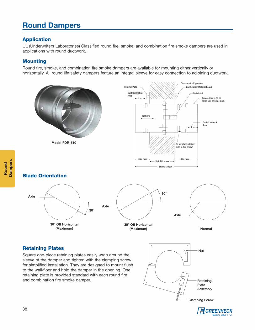
Ro
un
d
Da
mp
ers
38
Round Dampers
MountingRound fire, smoke, and combination fire smoke dampers are available for mounting either vertically or horizontally. All round life safety dampers feature an integral sleeve for easy connection to adjoining ductwork.
Retainer Plate
Duct ConnectionArea
2 in .
AIRFLOW
6 in. max.Wall Thickness
Sleeve Length
6 in. max.
Do not place retainerplate in this groove
2 in .
Duct C onnectionArea
Clearance for Expansion
2nd Retainer Plate (optional)
Blade Latch
Access door to be onsame side as blade latch
Retaining Plates Square one-piece retaining plates easily wrap around the sleeve of the damper and tighten with the clamping screw for simplified installation. They are designed to mount flush to the wall/floor and hold the damper in the opening. One retaining plate is provided standard with each round fire and combination fire smoke damper.
Blade Orientation
Normal
Axle
30° Off Horizontal
(Maximum)
Axle
30°
30° Off Horizontal
(Maximum)
Axle
30°
Clamping Screw
Retaining PlateAssembly
Nut
ApplicationUL (Underwriters Laboratories) Classified round fire, smoke, and combination fire smoke dampers are used in applications with round ductwork.
Model FDR-510
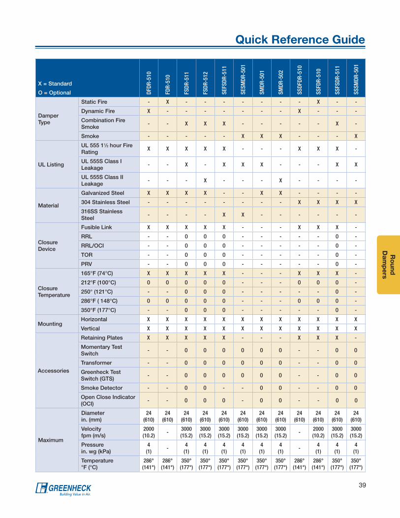
Ro
un
d
Da
mp
ers
39
Quick Reference Guide
X = Standard
O = Optional DFDR
-510
FDR-
510
FSDR
-511
FSDR
-512
SEFS
DR-5
11
SESM
DR-5
01
SMDR
-501
SMDR
-502
SSDF
DR-5
10
SSFD
R-51
0
SSFS
DR-5
11
SSSM
DR-5
01
Damper Type
Static Fire - X - - - - - - - X - -
Dynamic Fire X - - - - - - - X - - -
Combination Fire Smoke
- - X X X - - - - - X -
Smoke - - - - - X X X - - - X
UL Listing
UL 555 11⁄2 hour Fire Rating
X X X X X - - - X X X -
UL 555S Class I Leakage
- - X - X X X - - - X X
UL 555S Class II Leakage
- - - X - - - X - - - -
Material
Galvanized Steel X X X X - - X X - - - -
304 Stainless Steel - - - - - - - - X X X X
316SS Stainless Steel
- - - - X X - - - - - -
Closure Device
Fusible Link X X X X X - - - X X X -
RRL - - O O O - - - - - O -
RRL/OCI - - O O O - - - - - O -
TOR - - O O O - - - - - O -
PRV - - O O O - - - - - O -
Closure Temperature
165°F (74°C) X X X X X - - - X X X -
212°F (100°C) O O O O O - - - O O O -
250° (121°C) - - O O O - - - - - O -
286°F ( 148°C) O O O O O - - - O O O -
350°F (177°C) - - O O O - - - - - O -
MountingHorizontal X X X X X X X X X X X X
Vertical X X X X X X X X X X X X
Accessories
Retaining Plates X X X X X - - - X X X -
Momentary Test Switch
- - O O O O O O - - O O
Transformer - - O O O O O O - - O O
Greenheck Test Switch (GTS)
- - O O O O O O - - O O
Smoke Detector - - O O - - O O - - O O
Open Close Indicator (OCI)
- - O O O - O O - - O O
Maximum
Diameter in. (mm)
24 (610)
24 (610)
24 (610)
24 (610)
24 (610)
24 (610)
24 (610)
24 (610)
24 (610)
24 (610)
24 (610)
24 (610)
Velocity fpm (m/s)
2000 (10.2)
-3000 (15.2)
3000 (15.2)
3000 (15.2)
3000 (15.2)
3000 (15.2)
3000 (15.2)
-2000 (10.2)
3000 (15.2)
3000 (15.2)
Pressure in. wg (kPa)
4 (1)
-4
(1)4
(1)4
(1)4
(1)4
(1)4
(1)-
4 (1)
4 (1)
4 (1)
Temperature °F (°C)
286° (141°)
286° (141°)
350° (177°)
350° (177°)
350° (177°)
350° (177°)
350° (177°)
350° (177°)
286° (141°)
286° (141°)
350° (177°)
350° (177°)
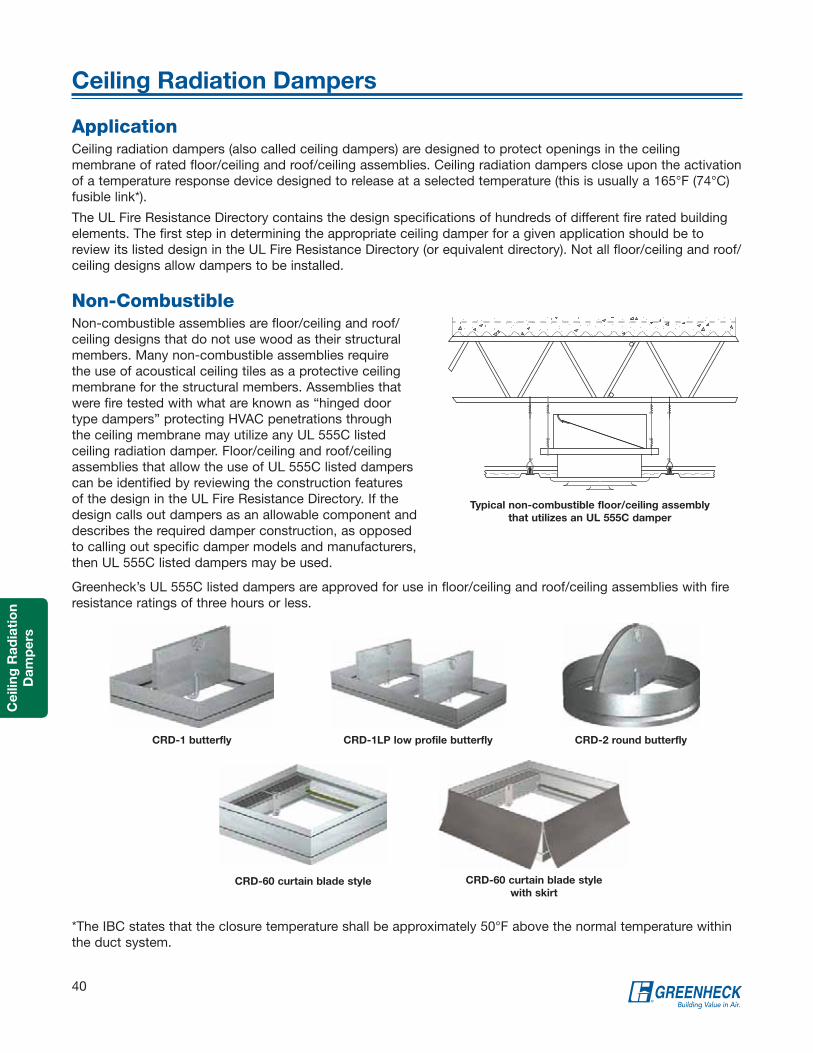
Ce
ilin
g R
ad
iati
on
Da
mp
ers
40
Ceiling Radiation Dampers
Non-CombustibleNon-combustible assemblies are floor/ceiling and roof/ceiling designs that do not use wood as their structural members. Many non-combustible assemblies require the use of acoustical ceiling tiles as a protective ceiling membrane for the structural members. Assemblies that were fire tested with what are known as “hinged door type dampers” protecting HVAC penetrations through the ceiling membrane may utilize any UL 555C listed ceiling radiation damper. Floor/ceiling and roof/ceiling assemblies that allow the use of UL 555C listed dampers can be identified by reviewing the construction features of the design in the UL Fire Resistance Directory. If the design calls out dampers as an allowable component and describes the required damper construction, as opposed to calling out specific damper models and manufacturers, then UL 555C listed dampers may be used.
ApplicationCeiling radiation dampers (also called ceiling dampers) are designed to protect openings in the ceiling membrane of rated floor/ceiling and roof/ceiling assemblies. Ceiling radiation dampers close upon the activation of a temperature response device designed to release at a selected temperature (this is usually a 165°F (74°C) fusible link*).
The UL Fire Resistance Directory contains the design specifications of hundreds of different fire rated building elements. The first step in determining the appropriate ceiling damper for a given application should be to review its listed design in the UL Fire Resistance Directory (or equivalent directory). Not all floor/ceiling and roof/ceiling designs allow dampers to be installed.
CRD-1 butterfly CRD-2 round butterfly
CRD-60 curtain blade style
CRD-1LP low profile butterfly
CRD-60 curtain blade style
with skirt
Greenheck’s UL 555C listed dampers are approved for use in floor/ceiling and roof/ceiling assemblies with fire resistance ratings of three hours or less.
Typical non-combustible floor/ceiling assembly
that utilizes an UL 555C damper
*The IBC states that the closure temperature shall be approximately 50°F above the normal temperature within the duct system.

Ce
iling
Ra
dia
tion
Da
mp
ers
41
Ceiling Radiation Dampers
CombustibleRated floor/ceiling and roof/ceiling assemblies that utilize wood trusses or wood joists as their structural membrane are often referred to as “Combustible Assemblies”. Because their structural members are combustible, most of these assemblies require the use of a gypsum board ceiling membrane. Combustible assemblies that were tested with HVAC penetrations in their ceiling membrane require the use of better insulated dampers. Dampers that only carry a UL 555C listing are not approved for these applications. Combustible designs in the UL Fire Resistance Directory that were tested with a damper, call out the specific damper manufacturer and models that are approved to be used. Because the tests for many of these designs were sponsored by a damper manufacturer, the approved damper models in a given design number may be limited to a single manufacturer. However, other damper manufacturer’s damper models are often approved to be used in different design numbers that permit the same construction material and methods.
Low Leakage Ceiling Radiation DamperThe CRD-501 is a round ceiling radiation damper with a Class I Smoke Leakage Rating. It is UL Classified as a ceiling radiation (UL 555C) and as a smoke damper (UL 555S). As a UL 555C ceiling radiation damper, it is used in floor/ceiling and roof/ceiling assemblies to maintain the fire resistance integrity of the assembly during fire exposure. As a UL 555S smoke damper, model CRD-501 is a Class I smoke leakage rated damper designed to control the spread of smoke.
CRD-501
Typical floor/ceiling assembly with wood joist
CRD-1WJ shown
t
Typical floor/ceiling assembly with wood truss
CRD-1WT shown

Ce
ilin
g R
ad
iati
on
Da
mp
ers
42
Ceiling Radiation Dampers
Ceiling Radiation Dampers - Models and Sizes
Butterfly Style Curtain Style Round
Model CRD-1CRD-1LP
Low ProfileCRD-1WJ CRD-1WT CRD-2WT CRD-60 CRD-60X CRD-2 CRD-501
Minimum Sizein. (mm)
4 x 6(102 x 152)
4 x 12(102 x 305)
4 x 6(102 x 152)
4 x 6(102 x 152)
5 x 5 (127 x 127)
6 x 4(152 x 102)
6 x 4(152 x 102)
5(127)
6(152)
Maximum Sizein. (mm)
24 x 24(610 x 610)
24 x 24(610 x 610)
16 x 12(406 x 305)
21 x 18(533 x 457)
12 x 12 (305 x 305)
24 x 24(610 x 610)
24 x 24(610 x 610)
24(610)
12(305)
Volume Controller
OptionsFrame Extensions
Top, bottom, or both top and bottom frame extensions are available on CRD-1, CRD-1LP, and CRD-2.
Mounting
Grille mount or duct mount for the CRD-1WT.
Plenum
The CRD-1WT dampers must have a plenum installed per UL. We can offer steel plenum, ductboard plenum, or they can choose to do a customer supplied plenum.
Thermal Blankets
Greenheck offers two different types of thermal blankets with ceiling radiation dampers to be used as batt and blanket material. QB-24 is a refractory thermal blanket consisting of a non-asbestos high temperature ceramic fiber blanket quilted between two layers of fiberglass cloth. The TB-24 is a non-asbestos mineral wool thermal blanket.
Volume Controller
A volume controller gives you the ability to regulate airflow through the damper by manually setting the blades to a given angle. Adjusting the screw will open or close the blades. Available on all CRD models.
Bottom and Top Extension
Top Extension
BottomExtension
Standard
Frame Extensions

Pe
rform
an
ce
Da
ta
43
Performance Data
Pressure drop testing was conducted in accordance with AMCA Standard 500-D using the three configurations shown. All data has been corrected to represent standard air at a density of .075 lb/ft3 (1.2 kg/m3).
Actual pressure drop found in a HVAC system is a combination of many factors. This pressure drop information, along with an analysis of other system influences should be used to estimate actual pressure losses for a damper installed in an HVAC system.
Figure 5.3 Illustrates a fully ducted damper. This configuration has the lowest pressure drop of the three test configurations because entrance and exit losses are minimized by straight duct runs upstream and downstream of the damper.
Figure 5.2 Illustrates a ducted damper exhausting air into an open area. This configuration has a lower pressure drop than Figure 5.5 because entrance losses are minimized by a straight duct run upstream of the damper.
Figure 5.5 Illustrates a plenum mounted damper. This configuration has the highest pressure drop because of high entrance and exit losses due to the sudden changes of area in the system.
5D 6D
Figure 5.3
Figure 5.2
5D
Figure 5.5
4 (W) (H)D=3.14
D = Duct lengthW = Damper widthH = Damper height
Greenheck Fan Corporation certifies that the models CFSD-211, 212; DFD-210; DFDAF-310, 330; SEDFD-210; FSD-211, 211M, 212, 213, 311, 311M, 312, 312M, 331; SSFSD-211; SEFSD-211; OFSD-211, 212, 311, 312; SMD-201, 201M, 202, 203, 301, 301M, 302, 302M, 401EF; SESMD-201 and SSSMD-201 shown herein are licensed to bear the AMCA Seal. The ratings shown are based on tests and procedures performed in accordance with AMCA Publication 511 and comply with the requirements of the AMCA Certified Ratings Programs. The AMCA Certified Ratings Seal applies to air performance only.

Pe
rfo
rma
nc
e
Da
ta
44
Pressure Drop
These pressure drop charts apply to the following models: CFSD-211, 212; DFD-210; SEDFD-210; FSD-211, 211M, 212, 213; OFSD-211, 212; SEFSD-211; SSFSD-211; SMD-201, 201M, 202, 203; SESMD-201; and SSSMD-201.
Dimension in. (mm)
12 x 12(305 x 305)
24 x 24(610 x 610)
36 x 36(914 x 914)
12 x 48(305 x 1219)
48 x 12(1219 x 305)
Velocity (ft/min.)
Pressure Drop - in. wg
500 .04 .02 .01 .01 .03
1000 .14 .07 .04 .06 .10
1500 .32 .16 .09 .13 .23
2000 .56 .29 .16 .23 .41
2500 .86 .45 .25 .36 .63
3000 1.24 .65 .36 .52 .91
3500 1.69 .89 .49 .70 1.24
4000 2.20 1.16 .64 .92 1.62
AMCA Figure 5.2 Pressure Drop
Dimension in. (mm)
12 x 12(305 x 305)
24 x 24(610 x 610)
36 x 36(914 x 914)
12 x 48(305 x 1219)
48 x 12(1219 x 305)
Velocity (ft/min.)
Pressure Drop - in. wg
500 .02 .01 .01 .01 .02
1000 .09 .04 .03 .04 .07
1500 .20 .09 .06 .10 .16
2000 .36 .16 .11 .17 .29
2500 .56 .25 .17 .27 .45
3000 .81 .35 .24 .39 .64
3500 1.10 .48 .33 .53 .88
4000 1.44 .63 .42 .70 1.14
AMCA Figure 5.3 Pressure Drop
Dimension in. (mm)
12 x 12(305 x 305)
24 x 24(610 x 610)
36 x 36(914 x 914)
12 x 48(305 x 1219)
48 x 12(1219 x 305)
Velocity (ft/min.)
Pressure Drop - in. wg
500 .06 .03 .03 .03 .04
1000 .22 .14 .12 .13 .17
1500 .50 .31 .26 .30 .38
2000 .89 .54 .46 .53 .67
2500 1.39 .85 .73 .83 1.04
3000 2.00 1.22 1.05 1.19 1.50
3500 2.72 1.66 1.42 1.62 2.05
4000 3.55 2.17 1.86 2.11 2.67
AMCA Figure 5.5 Pressure Drop

Pe
rform
an
ce
Da
ta
45
Pressure Drop
Dimension in. (mm)
12 x 12(305 x 305)
24 x 24(610 x 610)
36 x 36(914 x 914)
12 x 48(305 x 1219)
48 x 12(1219 x 305)
Velocity (ft/min.)
Pressure Drop - in. wg
500 .03 .01 .01 .01 .02
1000 .11 .06 .05 .05 .08
1500 .24 .12 .12 .12 .18
2000 .42 .22 .21 .21 .33
2500 .66 .34 .32 .33 .51
3000 .95 .49 .47 .48 .74
3500 1.30 .67 .63 .65 1.00
4000 1.70 .87 .83 .85 1.31
AMCA Figure 5.2 Pressure Drop
Dimension in. (mm)
12 x 12(305 x 305)
24 x 24(610 x 610)
36 x 36(914 x 914)
12 x 48(305 x 1219)
48 x 12(1219 x 305)
Velocity (ft/min.)
Pressure Drop - in. wg
500 .04 .03 .03 .03 .03
1000 .18 .13 .12 .12 .14
1500 .42 .29 .27 .27 .32
2000 .75 .52 .48 .49 .57
2500 1.17 .81 .75 .77 .89
3000 1.68 1.17 1.08 1.11 1.28
3500 2.29 1.60 1.48 1.51 1.75
4000 2.09 2.14 1.93 1.97 2.29
AMCA Figure 5.5 Pressure Drop
Dimension in. (mm)
12 x 12(305 x 305)
24 x 24(610 x 610)
36 x 36(914 x 914)
12 x 48(305 x 1219)
48 x 12(1219 x 305)
Velocity (ft/min.)
Pressure Drop - in. wg
500 .01 .01 .01 .01 .01
1000 .06 .02 .02 .03 .04
1500 .13 .06 .05 .06 .10
2000 .23 .10 .09 .11 .18
2500 .36 .16 .14 .18 .29
3000 .53 .23 .21 .25 .42
3500 .73 .32 .29 .34 .57
4000 .95 .42 .38 .45 .74
AMCA Figure 5.3 Pressure Drop
These pressure drop charts apply to the following models: DFDAF-310, 330; FSD-311, 311M; FSD-312, 312M; FSD-331; OFSD-311, 312; SMD-301, 302; SMD-301M and 302M.

Pe
rfo
rma
nc
e
Da
ta
46
Pressure Drop
These pressure drop charts apply to the following models: SMD-401, SMD-401M, and SMD-401EF.
Dimension in. (mm)
12 x 12(305 x 305)
24 x 24(610 x 610)
36 x 36(914 x 914)
12 x 48(305 x 1219)
48 x 12(1219 x 305)
Velocity (ft/min.)
Pressure Drop - in. wg
500 .01 .01 .01 .01 .01
1000 .06 .04 .03 .06 .03
1500 .13 .10 .06 .13 .06
2000 .23 .18 .12 .23 .10
2500 .35 .28 .18 .36 .16
3000 .50 .40 .26 .51 .23
3500 .68 .54 .35 .71 .30
4000 .88 .70 .46 .93 .39
AMCA Figure 5.2 Pressure Drop
Dimension in. (mm)
12 x 12(305 x 305)
24 x 24(610 x 610)
36 x 36(914 x 914)
12 x 48(305 x 1219)
48 x 12(1219 x 305)
Velocity (ft/min.)
Pressure Drop - in. wg
500 .04 .03 .03 .03 .03
1000 .14 .12 .10 .11 .11
1500 .31 .27 .22 .25 .26
2000 .55 .48 .39 .46 .46
2500 .86 .75 .61 .72 .72
3000 1.23 1.07 .87 1.05 1.02
3500 1.67 1.47 1.19 1.43 1.40
4000 2.19 1.91 1.56 1.87 1.83
AMCA Figure 5.5 Pressure Drop
Dimension in. (mm)
12 x 12(305 x 305)
24 x 24(610 x 610)
36 x 36(914 x 914)
12 x 48(305 x 1219)
48 x 12(1219 x 305)
Velocity (ft/min.)
Pressure Drop - in. wg
500 .01 .01 .01 .01 .01
1000 .03 .02 .01 .03 .02
1500 .07 .04 .02 .06 .04
2000 .14 .08 .04 .11 .08
2500 .21 .13 .06 .17 .12
3000 .29 .19 .09 .25 .18
3500 .39 .26 .13 .34 .24
4000 .51 .34 .17 .45 .31
AMCA Figure 5.3 Pressure Drop
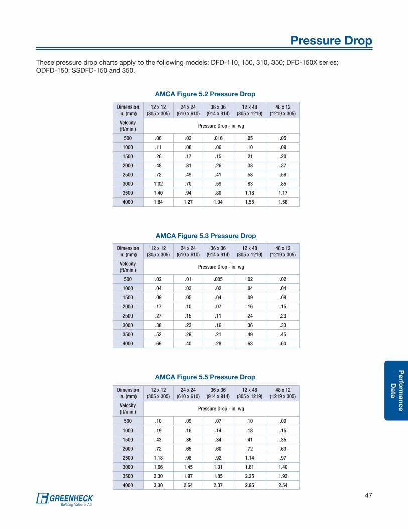
Pe
rform
an
ce
Da
ta
47
Pressure Drop
Dimension in. (mm)
12 x 12(305 x 305)
24 x 24(610 x 610)
36 x 36(914 x 914)
12 x 48(305 x 1219)
48 x 12(1219 x 305)
Velocity (ft/min.)
Pressure Drop - in. wg
500 .06 .02 .016 .05 .05
1000 .11 .08 .06 .10 .09
1500 .26 .17 .15 .21 .20
2000 .48 .31 .26 .38 .37
2500 .72 .49 .41 .58 .58
3000 1.02 .70 .59 .83 .85
3500 1.40 .94 .80 1.18 1.17
4000 1.84 1.27 1.04 1.55 1.58
AMCA Figure 5.2 Pressure Drop
Dimension in. (mm)
12 x 12(305 x 305)
24 x 24(610 x 610)
36 x 36(914 x 914)
12 x 48(305 x 1219)
48 x 12(1219 x 305)
Velocity (ft/min.)
Pressure Drop - in. wg
500 .10 .09 .07 .10 .09
1000 .19 .16 .14 .18 .15
1500 .43 .36 .34 .41 .35
2000 .72 .65 .60 .72 .63
2500 1.18 .98 .92 1.14 .97
3000 1.66 1.45 1.31 1.61 1.40
3500 2.30 1.97 1.85 2.25 1.92
4000 3.30 2.64 2.37 2.95 2.54
AMCA Figure 5.5 Pressure Drop
Dimension in. (mm)
12 x 12(305 x 305)
24 x 24(610 x 610)
36 x 36(914 x 914)
12 x 48(305 x 1219)
48 x 12(1219 x 305)
Velocity (ft/min.)
Pressure Drop - in. wg
500 .02 .01 .005 .02 .02
1000 .04 .03 .02 .04 .04
1500 .09 .05 .04 .09 .09
2000 .17 .10 .07 .16 .15
2500 .27 .15 .11 .24 .23
3000 .38 .23 .16 .36 .33
3500 .52 .29 .21 .49 .45
4000 .69 .40 .28 .63 .60
AMCA Figure 5.3 Pressure Drop
These pressure drop charts apply to the following models: DFD-110, 150, 310, 350; DFD-150X series; ODFD-150; SSDFD-150 and 350.

Ac
ce
sso
rie
s
48
Factory Mounted Accessories
Access DoorsAccording to NFPA 80 and NFPA 90A, an access door needs to be provided in air ducts adjacent to each fire damper, smoke damper, or combination fire smoke damper for maintenance and inspection.
Let Greenheck install the access door in the sleeve to save on time and labor costs in the field.
Retaining AngleSave time by letting Greenheck install retaining angles for you. You can order your retaining angles four different ways:
• Single Fastened - one retaining angle mounted in the location you want
• Single Wrapped - one retaining angle wrapped around the damper sleeve and wire tied
• Double Wrapped - the same feature as single wrapped, but with 2 sets of retaining angles
• Fastened and Wrapped - one retaining angle fastened and one angle wrapped around the damper
Quick Connect Breakaway ConnectionsGreenheck was the first manufacturer to successfully UL Qualify a universal breakaway duct connection that is compatible with TDC, TDF, Ductmate, Durodyne, Radiant T35m, MEZ, Nexus, or Ward flange systems. You now have the option to choose the universal breakaway connection on fire dampers, smoke, and combination fire smoke dampers. You can order your dampers with breakaway connection three different ways:
• Universal flange attached to one end of the sleeve
• Universal flange attached to both ends of the sleeve
• One end attached and one shipped loose
S and Drive connection uses drive slip connection on the side of the hemmed sleeve and S-slip joints are used on top and bottom.
To view the UL 555 Duct Impact Test showing the benefit of a Quick Connect Breakaway Connection, visit our resource video library at greenheck.com.

Ac
ce
sso
ries
49
Testing Devices
GTS-1
Momentary Test Switch
Greenheck has a wide range of devices to test your combination fire smoke or smoke damper.
GTS-1
• Combination fire smoke damper equipped with TOR
• Toggle switch
• Indicator lights- Red for closed damper- Green for open damper
• Factory mounted or shipped loose
GTS-2
• Combination fire smoke damper equipped with TOR
• Key switch
• Indicator lights- Red for closed damper- Green for open damper
• Shipped loose
GTS-3
• Combination fire smoke damper equipped with RRL/OCI or TOR
• Smoke damper with an OCI
• Indicator lights- Red for closed damper- Green for open damper
• Momentary test switch
• Factory mounted or shipped loose
GTS-4
• Combination fire smoke damper equipped with RRL/OCI or TOR
• Smoke damper with an OCI
• Indicator lights only- Red for closed damper- Green for open damper
• Factory mounted or shipped loose
Momentary Test Switch
• Combination fire smoke or smoke damper
• Test and cycle the damper on location
• Factory mounted
Two Position Toggle Switch
• Combination fire smoke or smoke damper
• Open and closes the damper
• Factory mounted Toggle Switch
GTS-2
GTS-3
GTS-4

Ac
ce
sso
rie
s
50
Blade Indicators and Smoke Detectors
Blade IndicationOpen Close Indicator (OCI) - The OCI option provides two switches, providing positive blade indication. One indicates when the damper is open, and the other indicates when the damper is closed. The switches are physically linked to a damper blade and therefore give true “positive blade indications”.
Actuator End SwitchesActuator end switches are also commonly referred to as auxiliary switches. These switches are internal to the actuator and perform the same function as the OCI option. These switches are also normally wired to indicator lights (at the Firefighter’s Smoke Control Station), or used for other purposes as required. The end switches are offered as an alternative to the OCI option based on preference of the design engineer.
Smoke DetectorsA smoke detector’s purpose is to sample air passing through a duct and provide an alarm upon detection of smoke. The detectors can be used to control smoke and combination fire smoke dampers.
Low Flow Smoke Detector - This smoke detector is rated for velocities from 100 to 4000 ft/min. (0.5 to 20.3 m/s). These smoke detectors can either be factory mounted and wired or shipped loose.
No Flow Smoke Detector - The no flow smoke detector is rated for systems without a minimum operating velocity. This smoke detector is rated for air velocities from 0 to 3000 ft/min. (0 to 15.2 m/s) and is mounted internally to the damper sleeve. It can be used on dampers with a maximum of two actuators. The no flow smoke detector has a built-in test switch.
Security BarsWhen a specification requires security bars to be installed with the damper, they can be shipped assembled. Installation of security bars into dampers reduces security risks and reinforces the equipment. Security bars maintain the UL Classification for all products and are welded into the sleeve. Two types of security bars are available:
• Cross bar - round steel bars placed horizontal and vertical on center, based on customer selection or
• Punched mid bar - round steel bars placed vertical on center, based on customer selection, with flat mid bars placed horizontal on dampers higher than 24 inches (610mm).
OCI
Low Flow
No Flow
Security Bars

Ac
ce
sso
ries
51
Transitions and Installation
Clean WrapIn the Indoor Air Quality section of the Green Building and LEED Core Concepts Guide, you need to protect air quality during construction and prevent dust and particulate buildup. Greenheck offers Clean Wrap to help meet this requirement. Clean Wrap is a thin film that adheres to the ends of the damper sleeve to prevent dust, dirt and debris from entering the damper at the construction site.
Helpful Installation DecalsGreenheck dampers feature decals highlighting damper areas that are important to an accurate installation. Our decals point out critical damper areas and include messages to make installation hassle-free. We are the only damper manufacturer to offer these simple, yet very helpful tips, right on the damper.
Installation BookletsGreenheck includes installation booklets in every shipment of dampers. These booklets include installation guidelines such as field-supplied sleeves, single side retaining angles, and much more to help with your installation needs.
TransitionsWhen a rectangular combination fire smoke or smoke damper is being used in conjunction with round or oval ductwork, it must be supplied with round or oval transitions on one or both ends of the sleeve. A Type C transition may be used to increase free area and minimize pressure drop. Dampers should be ordered to the duct dimensions.
Transitions for Smoke and Combination Fire Smoke Dampers
TYPE R TYPE O TYPE C

Ac
ce
sso
rie
s
52
Convenience Features
Tag LabelGreenheck labels—on all dampers—include the tag information for your order (30 character limit). This label provides the damper model, size, actuator model, and purchase order number. This label will help save time in the field when you have multiple locations for dampers on the job site. On combination fire smoke, smoke and fire dampers, you will see a QR code on the label too. When you scan the QR code with your smartphone, you will be directed to www.greenheck.com for model specific information.
One Piece Retaining AnglesGreenheck’s one piece retaining angle, the POC (literally named for being a “Piece of Cake”) makes combination fire smoke damper installation a breeze. The POC simply wraps around the sleeve of the damper, connections are made as described in our installation instructions, and that’s it! Simple! Like their rectangular counterparts, round one-piece retaining plates easily wrap around the sleeve of the damper and tighten with the clamping screw for simplified installation.
Maximum Qualified Damper Size for Single Side and 3-Side* Retaining Angle
(Width x Height)
Mounting Inches Millimeters
Vertical*80 x 50 2032 x 1270
50 x 80 1270 x 2032
40 x 100 1016 x 2540
Horizontal 144 x 96 3658 x 2438
Round Fire and Fire Smoke
24 diameter 610 diameter
Single Side Retaining Angles and PlatesRectangular dampers and sleeve assemblies are qualified for installations with retaining angles on one side of the partition only. Round dampers and sleeve assemblies may be installed with retaining plates on one side only. Damper assemblies exceeding these maximum sizes must be secured with retaining angles or plates on both sides of the partition.
A 3-side retaining angle is qualified in applications where the damper rests directly on the base of the wall opening (example: underfloor application). A retaining angle is not required on the bottom side of the damper.
Retaining Plate for
Round Dampers

Ac
ce
sso
ries
53
Cost Saving Products
Tight Space Constraints – Use FirestopWhere standard retaining angle installations will not work, Greenheck has a UL approved firestop and retaining clip installation which allows contractors to meet UL requirements where space limits capabilities.
Firestop and Retaining Clip InstallationMaximum Damper Size
(Width x Height)
Inches Millimeters
72 x 96 1829 x 2438
Two Dampers in One - Modulating Fire Smoke or Smoke DampersGreenheck offers UL approved modulating actuators on smoke and combination fire smoke dampers. A modulating actuator combines the functions of a control damper and a fire smoke or smoke damper into one unit reducing the number of dampers needed and the overall project cost.
Two Dampers in One - Manual Balancing Fire DamperThis allows them to function as both a fire damper and manual balancing damper. All Greenheck multi-blade fire dampers are supplied with a manual quadrant.

54
Damper Model Definition
EXAMPLE: Dynamic Fire Damper with 11⁄2 Hour Fire Rating 3-11⁄16 inch Frame Low to Medium Pressure 12 inch Integral Sleeve
A Product Type: Multi-Blade and RoundCFSD Corridor Ceiling Combination Fire Smoke DamperDFD Dynamic Fire Damper
DFDAF Dynamic Fire Damper - Airfoil Blade DamperDFDR Round Dynamic Fire DamperFDR Round Static Fire DamperFSD Combination Fire Smoke Damper
FSDR Round Combination Fire Smoke DamperGFSD Grille Access Combination Fire Smoke DamperHSD Heavy Duty Smoke DamperOFSD Out-of-Wall Combination Fire Smoke DamperSEDFD 316 Stainless Steel Dynamic Fire DamperSEFSD 316 Stainless Steel Combination Fire Smoke
DamperSEFSDR Round 316 Stainless Steel Combination Fire
Smoke DamperSESMD 316 Stainless Steel Smoke Damper
SESMDR Round 316 Stainless Steel Smoke DamperSMD Smoke Damper
SMDR Round Smoke DamperSSDFDR Round 304 Stainless Steel Dynamic Fire DamperSSFDR Round 304 Stainless Steel Static Fire DamperSSFSD 304 Stainless Steel Combination Fire Smoke
DamperSSFSDR Round 304 Stainless Steel Combination Fire
Smoke DamperSSSMD 304 Stainless Steel Smoke Damper
SSSMDR Round 304 Stainless Steel Smoke DamperB Blade Style2 Fabricated Steel with Triple Vee Reinforcements
(3V)3 Fabricated Steel Airfoil
4 Extruded Aluminum Airfoil5 Round C Fire Rating0 Smoke Damper-No Fire Rating1 1½ Hour3 3 HourD Leakage0 No Leakage Rating1 Leakage Class l2 Leakage Class lI
3 Leakage Class lII
1 Product Type: CurtainDFD Dynamic Fire DamperFD Static Fire Damper
ODFD Out-of-Wall Dynamic Fire DamperOFD Out-of-Wall Static Fire Damper
SSDFD 304 Stainless Steel Dynamic Fire DamperSSFD 304 Stainless Steel Static Fire Damper
2 Fire Resistance Rating1 1½ Hour3 3 Hour3 Frame Style0 Ultrathin - 1½ in. (38mm)1 Narrowline - 23⁄16 in. (56mm)5 Standard - 311⁄16 in. (94mm)4 Pressure Rating0 Pressure (up to 4 in. wg)
5 Damper with Integral Sleeve
X12 12 in. long
X14 14 in. long
X16 16 in. long
DFD -150X121 2 3 4 5
EXAMPLE: Combination Fire-Smoke Damper with Vertical Steel Airfoil Blades 11⁄2 Hour Fire Rating Class I Leakage
FSD-311VV = Vertical Blade
M = Modulating Blade
EF = Extruded Frame
A B C D

55
Drive Arrangement Definition
Listings/Approvals
1 Number of sections wide2 Number of sections high3 Number of actuators4 Who supplies the actuators
F = Factory (always) on UL dampers5 Actuator mounting
E = External
I = Internal
B = Both internal and external6 Actuator location (viewed from
jackshaft side)
L = Left hand drive
R = Right hand drive
B = Both right and left7 Number of jackshaftsDamper Width
Dam
per
Hei
ght
Actuator
Jackshaft
Jackshaft
Actuator
22-2FEL-21 2 3 4 5 6 7
UL Category EMME/CABS (all models)
California State Fire Marshal
EMME R13317
DFD-2xx; DFDAF-3xx; SSDFD-2xx 3225-0981:0103
All DFD/FD curtain style 3225-0981:0102
GFSD/FSD/OFSD/SSFSD (fire) 3225-0981:0103
GFSD/FSD/OFSD/SSFSD/SMD/SSSMD (leakage) 3230-0981:0104
CFSD (leakage) 3230-0981:0105
CFSD (fire) 3225-0981:0106
DFDR/FDR/FSDR/SSFSDR (fire) 3225-0981:0112
FSDR/SSFSDR/SMDR/SSSMDR (leakage) 3230-0981:0113
EMME R13317 CABS R13446
CRD-501 3230-0981:0113
CABS R13446
CRD-1/CRD-1xx/CRD-2 3225-0981:0101
CRD-60, -60X 3226-0981:0111
CRD-2WT 3226-0981:0500
The following breakdown of a drive arrangement code is a good reference in understanding what each number and letter signifies.

56
Specification Checklist
Ceiling Radiation
Dampers
Combination Fire
Smoke DampersFire Dampers Smoke Dampers
UL StandardUL 555
UL 555C
UL 555SNFPA
80
90A
92
101
105Fire Resistance
1½ Hour
3 HourFire Closure Temperature
165°F (74°C)
212°F (100°C)
250°F (121°C)
286°F (141°C)
350°F (177°C)Elevated Operational Temperature
250°F (121°C)
350°F (177°C)Differential Pressure (applies to dynamic rated fire dampers, combination fire smoke dampers, smoke dampers)
4 in. wg (1 kPa)
6 in. wg (1.5 kPa)
8 in. wg (2 kPa)
10 in. wg (2.5 kPa)Velocity
2000 ft/min. (10 m/s)
3000 ft/min. (15 m/s)
4000 ft/min. (20 m/s)Leakage
Class I
Class II
Class IIIMounting
Horizontal
VerticalFactory Mounted Actuators
Please visit our website at www.greenheck.com/products/air-control/dampers for complete specifications.

57
Modifications to Life Safety Dampers
Field ModificationsThe UL mark applies to the product as it is originally manufactured when shipped from the factory. UL does not know what effect a modification may have on the safety of the product or the continued validity of the UL certification mark unless the field modifications have been specifically investigated by UL. Unless UL investigates a modified product, UL cannot indicate that the product continues to meet UL’s safety requirements.
Design ModificationsCareful considerations need to be given to alterations or modifications of the fire resistance assemblies. When field issues arise, it is recommended the first contact for assistance be the technical staff provided by the product manufacturer noted for the design. Users of fire resistance assemblies are advised to consult the general Guide Information for each product category and each group of assemblies. The Guide Information includes specifics concerning alternate materials and alternate methods of construction.
Contacting ULUL provides assistance to the users of fire resistance assemblies and products, which includes clarification of the published information.
UL also provides a service to investigate modifications to the fire resistance assemblies when requested by the design submitter. Requests for clarification should describe the change and include drawings, if necessary.
Requests for clarifications or investigations can be made by contacting UL at:
• Phone 1-877-ULHELPS (1-877-854-3577) ext. 49590 • Email: [email protected] or • Website: www.ul.com.
Steps to Take When an Unapproved Installation Must be Provided 1. Identify the problem and be ready to explain why
an approved installation cannot be made.
2. Research the alternate installation methods that may be applicable and select a practical alternative that provides relative equivalency based on engineering principles.
3. Illustrate your proposed alternative and discuss it with the damper manufacturer (or representative), job design engineer, or both. Obtain an agreement that it is an acceptable alternative.
4. Submit your alternative damper installation to the authority having jurisdiction and obtain formal approval. Only the authority having jurisdiction can approve an alternative combination fire smoke damper installation. It is usually much easier to obtain approval before a damper has been installed. After an installation has been rejected by the inspector, it is often quite difficult to obtain approval.

58
Most Commonly Asked Questions
Q. Are pneumatic actuators available on smoke and combination fire smoke dampers?A. Smoke and combination fire smoke dampers are available with pneumatic or electric actuators (internal or
external mount).
Reference: Actuator Selection, page 25
Q. Does the smoke and combination fire smoke damper actuator have to be factory mounted by the damper manufacturer?
A. Yes. The 7th Edition of UL 555 and 4th Edition of UL 555S require all actuators on smoke and combination fire smoke dampers to be factory mounted.
Reference: Smoke Dampers Installation, page 22
Q. Are there any specific sleeve gauge requirements for combination fire smoke damper installation?A. Sleeve gauge or thickness requirements depend on damper size and the type of duct-to-sleeve connections
used.
Reference: Sleeve Requirements, page 8
Q. How much space outside the damper sleeve is required to accommodate the actuator installation? Can the actuators be installed inside the sleeve to eliminate external space requirements?
A. Clearance requirements for externally mounted actuators vary with actuator type. Enough space should be provided to allow for connection of wiring or piping and the replacement of the actuator and/or control components. If clearance is potentially a problem, the damper manufacturer should be contacted for specific clearance requirements. Installing the actuators internally should be considered only as a last resort, as it creates wiring/piping and service difficulties.
Q. How should combination fire smoke dampers be installed?A. Combination fire smoke dampers must always be installed in accordance with the manufacturer’s installation
instructions.
References: Fire Dampers Installation, page 7 through 10 Smoke Dampers Installation, page 22 Combination Fire Smoke Dampers Installation, page 30 through 31
Q. Is there any fire, smoke or combination fire smoke dampers that can be used in corrosive environment applications?
A. Greenheck has Severe Environment dampers that are constructed out of 316 stainless steel for this application.
Reference: Damper Model Definition, page 54
Q. When do I use a ceiling radiation damper versus a fire damper?A. Both dampers are intended to protect openings in horizontal fire barriers. A fire damper is required in a
fire rated wall, floor or ceiling or partition when it is penetrated by air ducts or other air transfer openings. A ceiling radiation damper, according to the 2015 IBC (International Building Code). should be used in the following situations: 1. A ceiling radiation damper installed where a duct penetrates the ceiling of a fire resistance rated floor/
ceiling or roof/ceiling assembly.
2. A ceiling radiation damper installed at the ceiling line where a diffuser with no duct attached penetrates the ceiling of a fire resistance rated floor/ceiling or roof/ceiling assembly.
Reference: Ceiling Radiation Dampers, page 40 through 42

59
Inspection, Maintenance and Testing
Inspection and TestingOnce a building is commissioned, the dampers are required to be inspected and tested one year after installation. After one year, the dampers are inspected and tested every 4 years, except in a building containing a hospital, the frequency is every six years per NFPA 80 and NFPA 105.
Dampers are part of the smoke control system and are required to be tested along with the system. Per NFPA 92, the smoke control system is inspected and tested:
• At least semi-annually if it’s a dedicated system
• At least annually if it’s a non-dedicated system
The damper actuator shall be inspected and cycled per the manufacturer’s recommendations.
MaintenanceDampers do not typically require maintenance as long as they are kept dry and clean. If cleaning is necessary, use mild detergents or solvents. If lubrication is desired for components such as axle bearings, jackshaft bearings, and jamb seals, do not use oil-based lubricants or any other lubricants that attracts contaminants such as dust.
If the damper and/or the actuator are not operable, repairs shall begin as soon as possible.

P.O. Box 410 • Schofield, WI 54476-0410 • Phone (715) 359-6171 • greenheck.com
Greenheck delivers value
to mechanical engineers by
helping them solve virtually
any air quality challenges
their clients face with a
comprehensive selection of
top quality, innovative air-
related equipment. We offer
extra value to contractors
by providing easy-to-install,
competitively priced, reliable
products that arrive on time.
And building owners and
occupants value the energy
efficiency, low maintenance
and quiet dependable operation
they experience long after the
construction project ends.
Building Value in Air
As a result of our commitment to continuous improvement, Greenheck reserves the right to change
specifications without notice.
Specific Greenheck product warranties are located on greenheck.com within the product
area tabs and in the Library under Warranties.
Our Commitment
Prepared to SupportGreen Building Efforts
Greenheck has a complete line of dampers for your needs!
00.DMP.1000 R5 6-2018 SPCopyright © 2018 Greenheck Fan Corp.
• Commercial Control Dampers
• Industrial Control Dampers
• Combination Fire, Smoke, Fire and Smoke Dampers
• Ceiling Radiation Dampers
• Backdraft Dampers
• Pressure Relief Dampers
• Balancing Dampers
• Access Doors
• Marine Products
• Severe Environment Dampers
• Industrial Smoke Dampers
• Insulated Thermally Broken Dampers
• Air Measuring Dampers
• Pressure Relief Dampers
• Barometric Relief Dampers
• Industrial Backdraft Dampers
• Tunnel Transit Dampers
• Bubble-Tight Dampers
• Blast and Tornado Dampers
• Shock Dampers
CCCCCCCCConononononononononontrtrtrtrtrtrtrtrrolololololoolooo ••••••• AAAcAcAcAcAcAcAcAAA cecececececececec sssssssssssssssss DDDDDDDDDDDooooooooooooooooooo rsrsrsrsrsrsrsss •••••••• BaBaBaBaBaBaBBaB rororororororoor memememememeememeemetrtrtrtrtrtrtrrricicicicicicicicc RRRRRRRRRR
Bubble-Tight Dampers
HBTR Series
Zero Leakage
March
2016
Tunnel Transit Dampers
• Heavy Duty Tunnel Transit
• Life Safety
November
2017
1
®
A Global PresenceMarine ProductsDampers, Louvers, and Fans• Selection • Construction • Performance
February2016
January2014
Heavy-Duty/Industrial Dampers
HB, HBTR, HPR, HCD, HCDR, HSD, and HTD Series
HVAC Control & Balancing Dampers
Models VCD, ICD, FBH, FBV, MBD and RBD
• Selection • Construction • Performance
January
2018
Life Safety Dampers
• Fire • Combination Fire Smoke
• Smoke • Ceiling Radiation
June2018
mokee
uJunJunJuneJuneuneJuneu eeuJuneJuneeJ eJuneJuJJunuunnJJuJuunnnnJJu101820180 80180182018820120201820 8220001188201822018200202
m
JJannuaryuaryyJaaannanannn22201420144422