Embed Size (px)
Citation preview

Greenheck Coils A Complete Line of Custom Coils to Meet Your Needs3/8, 1/2 and 5/8 inch OD Tubing
March2010

2
Custom Coils
Custom Coils Configured to Meet Your NeedsGreenheck is proud to offer a complete line of competitively priced, quality engineered replacement and OEM coils. Coils are made from the finest materials to your specifications and then tested with high pressure dry nitrogen gas for 100% quality assurance. Greenheck’s experienced team of application specialists are only a phone call away and ready to respond to any questions you may have.
Quick Build ProgramAt Greenheck, our Quick Build (QB) program ensures that your coils will be manufactured to your specifications and shipped to meet your time requirements. We work together as a team to match the exact measurements and the performance requirements you need.
Our efficient system can design and manufacture most custom coils for you in 3-, 5-, or 10-day turnarounds. Contact your local Greenheck Representative for more information on our Quick Build program or to order a coil.
World Class ManufacturingGreenheck’s custom coils are manufactured using advanced processes, superior engineering, and quality control procedures to guarantee the highest quality product. Highly skilled production workers use cost-efficient machines and unique die designs to add innovative features. And just to be sure you get the performance you expect when you specify Greenheck, our coils are tested in accordance with AHRI Standard 410-2001 and every coils bears the AHRI label.
Leading Edge Technical SupportGreenheck’s products are supported by the industry’s best product literature, electronic media, and selection software programs. Greenheck Coil technical literature, specifications, Installation, Operation, and Maintenance manual (IOM), and our Coil Selection software program is available at www.greenheck.com
You can always count on personal service and expertise from our network of Greenheck representatives. To locate your local Greenheck representative, call 715-359-6171 or visit our Web site.
To guarantee your coil is going to perform as required, check for AHRI Certification.

3
Coil Applications
Heating / CoolingGreenheck coils are designed, manufactured and tested to meet a broad range of heating and cooling requirements. To achieve maximum efficiency and longevity, coils must be properly sized for the intended application.
Water Coils can be used for a single purpose such as heating or cooling, or their function can be alternated between heating and cooling by changing the temperature of the water flowing through the coil. Depending on the application, it may be necessary to use a glycol mixture to prevent the liquid from freezing. Greenheck water coils are engineered to operate at pressures up to 250 PSIG and temperatures up to 300°F, but ancillary equipment such as valves and pumps will often dictate lower operating temperatures. All water coils are pressure tested at the factory with 450 PSIG of dry nitrogen.
Steam Coils are used for heating applications and are built to operate at pressures of up to 125 PSIG with a maximum temperature of 353°F. They are pressure tested with 600 PSIG of dry nitrogen. The most frequent use of steam coils is for retrofitting or modifying existing steam heat systems.
Direct Expansion (DX) Coils are part of a refrigerant filled system consisting of a condenser coil, evaporator coil and a refrigerant compressor. The evaporator coil must be paired with a thermal expansion valve (TXV) intended for the specific capacity and refrigerant type. When used in conjunction with a heat pump and reversing valves, a coil serves for both heating and cooling.
Evaporator Coils (DX) are made for heat absorption and generally function at a lower pressure. Coils made with 3/8-inch diameter tubing are rated for 400 PSIG and 300°F maximum operating temperature. Coils made with 1/2- or 5/8-inch diameter tubing are rated for 250 PSIG and a maximum operating temperature of 300°F. All evaporator coils are factory tested at 600 PSIG. These coils are generally used for spot cooling or as part of an air handling system.
Condenser Coils are made for heat rejection, such as the heat absorbed by an evaporator coil, and they typically operate under higher internal pressures. Coils made with 3/8-inch tubing are rated for use at 600 PSIG and 300°F while coils made from 1/2- or 5/8-inch tubing are rated for 300 PSIG and 300°F. Condenser coils are sometimes used as part of a heat pump to provide heat in a specific location, but more often they are used to simply exhaust heat energy that is collected elsewhere. These coils are also factory tested to 600 PSIG.
DX Cooling Cycle
Outdoor Air Intake
Condenser Coils
Reheat Coil for Humidity Control
Evaporator Coil (DX) for cooling
4
Coil Applications
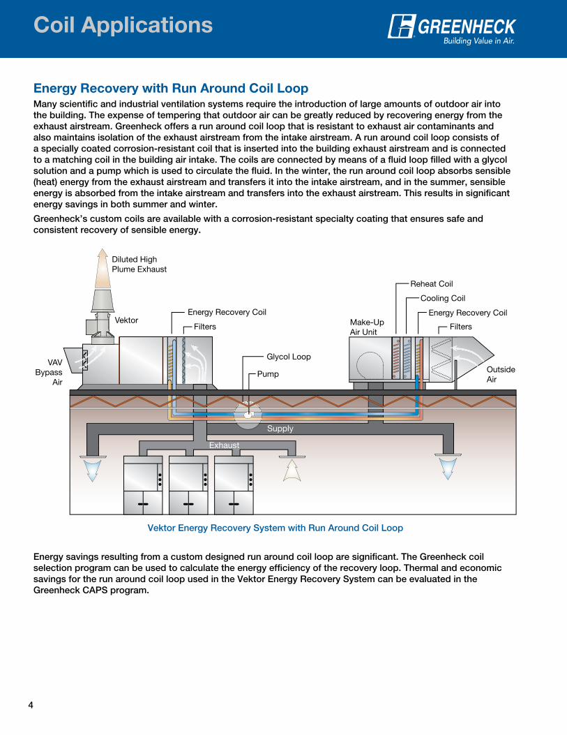
Energy Recovery with Run Around Coil LoopMany scientific and industrial ventilation systems require the introduction of large amounts of outdoor air into the building. The expense of tempering that outdoor air can be greatly reduced by recovering energy from the exhaust airstream. Greenheck offers a run around coil loop that is resistant to exhaust air contaminants and also maintains isolation of the exhaust airstream from the intake airstream. A run around coil loop consists of a specially coated corrosion-resistant coil that is inserted into the building exhaust airstream and is connected to a matching coil in the building air intake. The coils are connected by means of a fluid loop filled with a glycol solution and a pump which is used to circulate the fluid. In the winter, the run around coil loop absorbs sensible (heat) energy from the exhaust airstream and transfers it into the intake airstream, and in the summer, sensible energy is absorbed from the intake airstream and transfers into the exhaust airstream. This results in significant energy savings in both summer and winter.
Greenheck’s custom coils are available with a corrosion-resistant specialty coating that ensures safe and consistent recovery of sensible energy.
Energy savings resulting from a custom designed run around coil loop are significant. The Greenheck coil selection program can be used to calculate the energy efficiency of the recovery loop. Thermal and economic savings for the run around coil loop used in the Vektor Energy Recovery System can be evaluated in the Greenheck CAPS program.
Supply
Exhaust
Filters Vektor
Glycol Loop
Pump
Filters Make-UpAir Unit
Outside Air
Energy Recovery Coil
Diluted High Plume Exhaust
Energy Recovery Coil
Reheat Coil
Cooling Coil
VAVBypass
Air
Vektor Energy Recovery System with Run Around Coil Loop

5
Construction Features
Fin Materials• .006 in., .008 in. and .010 in. aluminum• .006 in. copper
Rows• Chilled water and DX coils – 1 to 12 rows• Hot water coils – 1 to 12 rows• Steam coils – 1 to 2 rows• Condenser coils – 1 to 12 rows
Construction Features and Options
• Chilled Water• Hot Water• DX Evaporator• Heat Reclaim• Condenser
• Standard Steam• Non-Freeze Steam
Distributing• Booster / Duct Mounted
Complete Line of Standard and Custom Built Coils
Headers• Type “L” or “M”
from 7⁄8 in. OD to 4 1⁄8 in. OD copper
Other Options• Nonstandard casing flange widths and
casing depths• Special coil coatings• Additional distributors• Nonstandard circuiting• Intertwined circuiting (DX Only)• Insulated coil sections
Optional Seamless Rifled Tubing• For enhanced performance
Brazing• All joints are
hand-brazed
Connections • Water and steam coils - Copper, steel or brass - MPT, FPT or
sweat connections• DX distributors - Standard or hot gas• DX, condenser and
heat reclaim - Copper sweat connections• Supply connections on both
ends of steam distributing coils
Casings• 16 and 14 gauge galvanized steel• 16 gauge 304 stainless steel• Copper
Tube Material• 3⁄8 in. OD x .016 in.
wall, copper• 3⁄8 in. OD x .016 in.
wall rifled, copper (optional)
• 1⁄2 in. OD x .016 in., .020 in. wall, copper
• 5⁄8 in. OD x .020 in., .025 in., .035 in., .049 in. copper
Fin Spacing• 1⁄2 in. OD Tubing - 6 to 14 fins per in.• 5⁄8 in. OD Tubing - 6 to 14 fins per in.• 3⁄8 in. OD Tubing - 10 to 20 fins per in.

6
Quick Reference Chart
SUPPLY
STL
SP2 CLEP1CH EP2
DIMENSIONAL DATA IN INCHES SUPPLY RETURN
ITEM QTY FHROWS FPI SP1 FL
2 1/8
SWEAT FPT
1 2
86
53 4ROWS AVAILABLE
6 7 8FPI AVAILABLE
1/2
16 GA. STAINLESS STEEL
.025
.035 5/8
COPPER
1 3/8 1 5/8
2 5/8
7/85/8
3 1/8
TUBES OD & Wall Thickness COPPER
ONLY
FINS Material & Thickness
.016
.049
.006 ALUM.
P.O. #
W.O. #
CD E
MODEL NO.
CASING
LMAX C OAL
HEADERS COPPER
ONLY
CONNECTION SIZESMPT
R F RETURN CU
11
DATE NOTES
APPROVED BY TAG:
CUSTOMER
14
1 1/8
.010
.006
.020
16 GA. GALV. STEEL
10 12
109
13
EWT LWT GPM
S
CAPACITY
12
Performance Data CFM EDB/EWB LDB/LWB
®
Coil Selection ProgramSoftware Visit www.greenheck.com/software to obtain Greenheck’s coil selection software. Use of the self-explanatory software will guide the user in proper sizing and feature selection.
Coil Drawing WorksheetsReplacement Blank Coil Drawings—which are helpful for recording coil construction details when sizing and ordering replacement coils—are available from our Web site. The drawings are located on the Coils product Web page under the Other Product Information section.
Tube Diameter3/8 1/2 5/8
Wall Thickness (inches)0.016 0.020 0.025 0.035 0.049
Fin TypeAluminum Copper Fins Per Inch (FPI)Min 10 6 6Max 20 14 14Fin TypeSine wave Lanced Corrugated Flat Connection Size (inches)Min 0.5 0.5 0.5Max 4.0 4.0 4.0Fin Height (inches)Min 4.0 5.0 4.5Max 60 120 120Increments of 1.00 1.25 1.50
Refrigerant TypesR-22
R-134aR-404AR-407CR-410AR-502
Casing MaterialStandard Optional
16 gauge galvanized steel
14 gauge galvanized steel
16 gauge stainless steel
.06 or .09 in. thick copper
Fluid Flow RatesFor water coils, connections sizes are based on GPM of waterGPM 1-4 4-8 8-16 16-30 30-40 40-70 75-150Connection 3/4 1 1 1/4 1 1/2 2 2 1/2 3
Fin MaterialFin Material Aluminum Copper
Tube Diameter3/8 1/2 5/8
Fin Thickness0.006 0.008 0.010
Fin Type
Sine wave (5/8 inch only)
Lanced Corrugated Flat
Casing TypesStd. (1.5-inch flange)Standard Booster (1-inch flange)Slip and driveEndplates onlyInverted S.P. flange
Connection TypesFPT - Female pipe threadMPT - Male pipe threadSweat

7
Quick Reference Chart
Coil Type (Style)Custom Booster
Chilled Water
Hot Water
Direct Expansion
CondenserStandard
SteamSteam
DistributingHot
WaterStandard
Steam
Tube Diameter (inches)
3/8
1/2
5/8
Rows
Min Rows 1 1 1 1 1 1 1 1
Max Rows 12 12 12 12 2 2 2 2
Fin Height (inches)
Min
Fin height is dependent on tube diameter (see Tube Diameter chart)
6 6
Max 24 24
Increments of
3 3
Fin Length (inches)
Min Minimum fin length is 1 inch 6 6
Max Max fin length is 250 inches with center supports every 50 inches 48** 48**
Increments of
No restriction on fin length increments 1 1
Recommended Face Velocity (FPM)
Min 400 500 400 600 500 500 500 500
Max 550 800 550 750 850 850 800 850
Recommended Fluid Velocity (FPS - for water coils)
Min 1.5 1.5 NA NA NA NA 1.5 NA
Max 4.0 4.0 NA NA NA NA 4.0 NA
Recommended Pressure Drop (ft. of H2O or psi)
Min 1 1 1.5 3 1 1 1 1
Max 20 10 9 10 125* 125* 10 125*
* Higher steam pressures will require heavier tube wall thicknesses. ** Booster coil fin lengths are dependent on fin height.
Coil Measuring ToolGreenheck’s coil measuring tool helps the user determine the specifications to properly size a replacement coil. It will quickly, easily and accurately check tubing and connection diameters, and fins per inch (FPI).
Contact your local Greenheck representative to request a free coil measuring tool today.
400 Ross Avenue • P.O. Box 410 WI 54476-0410
Tel: 715-359-6171FAX: 715-355-2382
www.greenheck.come-mail [email protected]
Tub
e D
iam
eter Tub
e Diam
eter
Fins per inch
16 14 12 10 8 6 4
Connection Diameter
1 in
ch5/
8 in
ch
½ inch
3⁄8 inch
1 inch
1½ inch
2 inch
2½ inch

Greenheck warrants this equipment to be free from defects in material and workmanship for a period
of one year from the shipment date. Any units or parts which prove defective during the warranty
period will be replaced at our option when returned to our factory, transportation prepaid. Motors are
warranted by the motor manufacturer for a period of one year. Should motors furnished by Greenheck
prove defective during this period, they should be returned to the nearest authorized motor service
station. Greenheck will not be responsible for any removal or installation costs.
As a result of our commitment to continuous improvement, Greenheck reserves the right to change
specifications without notice.
Building Value in Air
Our Warranty
Greenheck delivers value to mechanical engineers by helping them solve virtually any air quality challenges their clients face with a comprehensive selection of
top quality, innovative air-related equipment. We offer extra value to contractors by providing easy-to-install, competitively priced, reliable products that arrive on time. And building
owners and occupants value the energy efficiency, low maintenance and quiet, dependable operation they experience long after the construction project ends.
Model Number Code
Greenheck’s Coil Measuring Tool
Z CW 58 S 04 F 10 24 x 36 RH
Coil TypeCW = Chilled WaterHW = Hot WaterDX = EvaporatorHR = Heat ReclaimCD = CondenserSS = Standard SteamSD = Steam DistributingDR = Evaporator, Rifled TubesCR = Condenser, Rifled Tubes
CircuitD = DoubleO = One-and-a-HalfF = FullT = Three-QuarterH = HalfQ = QuarterS = SpecialA = Single FeedB = 2 Feed
RH = Right HandLH = Left HandConnection hand is determined by looking at the inlet face of the coil, with the air hitting you in the back.
Tube Diameter58 = 5/8”12 = 1/2”38 = 3/8”
Z = Special Feature
Fins Per Inch6 - 18
Fin Height x Fin Length
Rows Deep01, 02, 03, 04, 05, 06, 08, 10, 12, etc.
Fin TypeS = Sine waveL = LancedC = CorrugatedF = Flat
Greenheck Coils
00.TAP.1039 R2 3-2010 RGCopyright © 2010 Greenheck Fan Corp.
Prepared to SupportGreen Building Efforts
Visit www.greenheck.com for specific coil worksheets to record the details below to help w/ replacement coil sizing
• Coil Type : water, booster, steam, steam distributing, DX, DX intertwined, condenser
• Coil Model # and manufacturer, design conditions and performance if known
• Dimensional data shown on the drawing, casing material (galvanized, stainless)
• Rows deep in direction of airflow, FPI, tube diameter, coil hand, connection size O.D. and type (MPT, FPT, Sweat)
400 Ross Avenue • P.O. Box 410
Schoifeld, WI
54476-0410
Tel: 715-359-6171
FAX: 715-355-2382
www.greenheck.com
e-mail [email protected]
Tube
Dia
met
er
Tube Diam
eter
Fins per inch
1614
1210
86
4
Connection Diameter
1 in
ch
5/8
inch
½ inch
3⁄8 inch
1 inch
1½ inch
2 inch
2½ inch
P.O. Box 410 • Schofield, WI 54476-0410 • Phone (715) 359-6171 • greenheck.com