Embed Size (px)
Citation preview

01801-08.14
Life Pulse® High Frequency Ventilator
In-Service Manual
436 Lawndale Drive Salt Lake City, UT 84115
Phone: 801-467-0800 Hotline: 800-800-4358 Fax: 801-467-0867 Website: www.bunl.com

i
In-service Manual TABLE OF CONTENTS
HOW TO USE THIS MANUAL 1 CHAPTER 1: OVERVIEW 2
HFV WITH CV 3 LIFEPORT ADAPTER 4
CHAPTER 2: SETUP 5 REAR PANEL CONNECTIONS 6 FRONT PANEL CONNECTIONS 7 PATIENT BOX CONNECTIONS 8 SETUP CAUTIONS 9
CHAPTER 3: VENTILATOR CONTROLS & TEST PROCEDURE 10 THE CONTROLS SECTION 11 PERFORMING A TEST 12 A FAILED TEST 12
CHAPTER 4: PRESSURE MONITORING 14 MONITOR DISPLAYS 15 PRESSING ENTER BUTTON 16 PURGE PAUSES 17
CHAPTER 5: HUMIDIFIER 18 GAS FLOW THROUGH HUMIDIFIER 19 STARTING THE HUMIDIFIER 21 CHANGING THE CIRCUIT 22 CIRCUIT CHANGE PREPARATIONS 22 CHECKLIST 22 FRONT PANEL DUTIES 22 PATIENT BOX DUTIES 23 POST-CIRCUIT CHANGE 23 AFTER ENTER BUTTON IS PRESSED: 23 IMPORTANT 24 TO COMPLETE A CIRCUIT CHANGE: 24 IDENTIFYING PROPER HUMIDIFICATION 25
CHAPTER 6: START UP 26 MEASURING & DISPLAYING PRESSURES 27 CHOOSING STARTING VALUES 28 6 STEPS TO START HFV 29
CHAPTER 7: PATIENT MANAGEMENT 32 CLINICAL OBJECTIVES 32 OXYGENATION 33 OXYGENATION OVEREXPANDED LUNGS 35 FINDING OPTIMAL PEEP 36 VENTILATION 37 UNDERSTANDING SERVO PRESSURE 39
CHAPTER 8: SUCTIONING THE PATIENT 40

ii
In-service Manual TABLE OF CONTENTS
CHAPTER 9: WEANING 41 GENERAL GUIDELINES FOR WEANING 41 CHAPTER 10: VENTILATOR ALARMS 44
READY LIGHT ON 44 ALARM LIMITS 45 JET VALVE FAULT 46 VENTILATOR FAULT: HFV CONTINUES RUNNING 47 VENTILATOR FAULT:HFV STOPS RUNNING 48 VENTILATOR FAULT: CODE 10 49 LOW GAS PRESSURE 50 CANNOT MEET PIP 51 LOSS OF PIP 52 HIGH PIP 53
CHAPTER 11: INTERPRETING VENTILATOR ALARMS 54 ALARM DISPLAY 54 LOOK AT THE PATIENT 55 USE COMMON SENSE 56 KNOW THE LIFE PULSE 57 COMMON THINGS HAPPEN COMMONLY 58 USE AVAILABLE RESOURCES 59
CHAPTER 12: HUMIDIFIER ALARMS 60 HUMIDIFIER OPERATION 61 CIRCUIT FAULT: LEVEL ALARM 62 WATER LEVEL SENSING 63 CIRCUIT TEMPERATURE 64 TEMPERATURE CONTROLS 65 SETTING CARTRIDGE TEMPERATURE 66 CONDENSATION PROBLEMS 67 MANUALLY PURGING 68 HIGH / LOW WATER LEVEL 69 HIGH / LOW TEMPERATURE 70
APPENDIX A: POST-TEST QUESTIONS 71 APPENDIX B: POST-TEST ANSWERS 85
1
Introduction HOW TO USE THIS MANUAL
Each chapter begins with a chapter designation
Each page will list its contents in large, bold, capitol letters
Text will appear in the right column
Objectives 1. Understand how to use this manual.
2. Know how to navigate to the information you need.
INSTRUCTION BOXES Boxes containing instructions and summaries of procedures will appear in lightly shaded boxes and will look like this.
WARNING: Warnings will also appear in lightly shaded boxes and will look like this.
CONTROLS
ON
STANDBY
STANDBYENTER ENTER
SILENCEENTER
Each chapter includes objectives for the reader
Graphics and instruction boxes will appear in the left column
Text that lists sequential procedures: 1. Is numbered 2. Like this Otherwise, lists will be: • Bulleted • Like this
Text that instructs you to press a button will highlight the button’s font like this: press MENU

2
Chapter 1 OVERVIEW
The Life Pulse High-Frequency Ventilator is a microprocessor-controlled infant ventilator capable of delivering and monitoring between 240 and 660 heated, humidified breaths per minute.
The Life Pulse is composed if 5 subsystems: MONITOR: Displays patient and machine pressures. ALARMS: Indicates various conditions that may require attention. CONTROLS: Regulates the On-Time, Peak Inspiratory Pressure, and Rate of the HFV breaths. HUMIDIFIER: Monitors and controls the temperature and humidification of gas flowing through the disposable humidifier circuit to the patient. PATIENT BOX: Contains the pinch valve that breaks the flow of pressurized gas into tiny jet pulses and sends pressure information back to the ventilator’s microprocessor. Together, these elements form a system that offers a variety of options for managing patients and the potential for improving blood gases using less pressure.
Objectives
1. Know the 5 subsystems of the Life Pulse and their purposes.
2. Understand the relationship between the Life Pulse and the conventional ventilator.
3. Know the structure and function of the LifePort adapter.
NOTE: Graphics that display illuminated indicator lamps (LEDs) in this manual reflect Life Pulse model 203. For model 203A, please refer to the table at right:
INDICATOR LED MODEL 203 MODEL 203A
STANDBY Red Yellow
TEST Red Yellow
JET VALVE OFF Red Yellow
READY Red Green
WAIT Red Yellow
CIRCUIT Red Yellow
CARTRIDGE Red Yellow
MONITOR ALARMS CONTROLS
PATIENT BOX HUMIDIFIER
3
HFV with CV
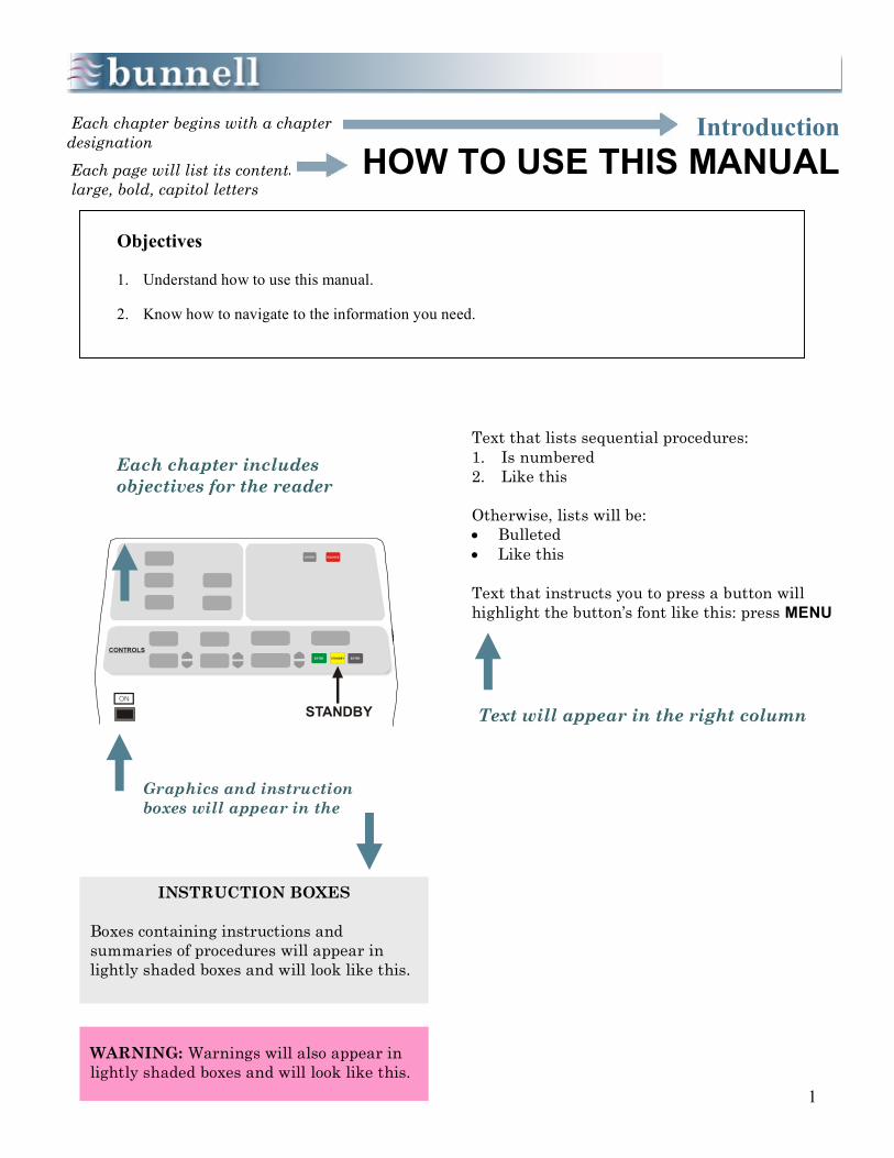
The Life Pulse is used in conjunction with a conventional infant ventilator. The conventional ventilator has 4 functions: • provides fresh gas for the patient’s
spontaneous breathing, • regulates PEEP, • provides supplementary IMV when needed,
and • provides periodic dilation of airways when
needed. The purpose of the supplementary IMV is to provide background breaths sufficient to recruit atelectatic alveoli. The purpose of the PEEP provided by the conventional ventilator is to maintain the inflation of alveoli with adequate FRC. Using IMV periodically to dilate airways without interrupting the Life Pulse affords opportunities to ventilate areas downstream from airway restrictions.
VENTILATOR FUNCTIONS
LIFE PULSE • High-frequency breaths • Airway pressure monitoring • Humidification • Alarms CONVENTIONAL VENTILATOR • Regulate PEEP • Fresh gas for spontaneous breathing • Supplementary IMV • Airway dilation
Life Pulse
Conventional Ventilator mounts here
4
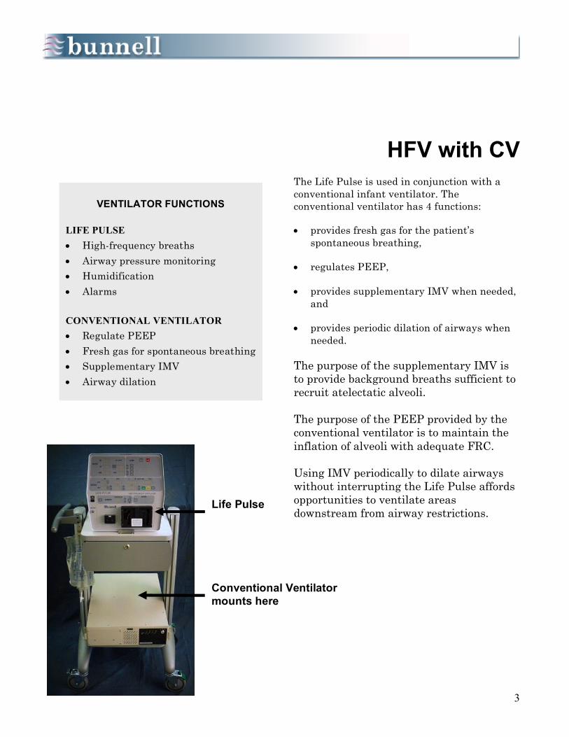
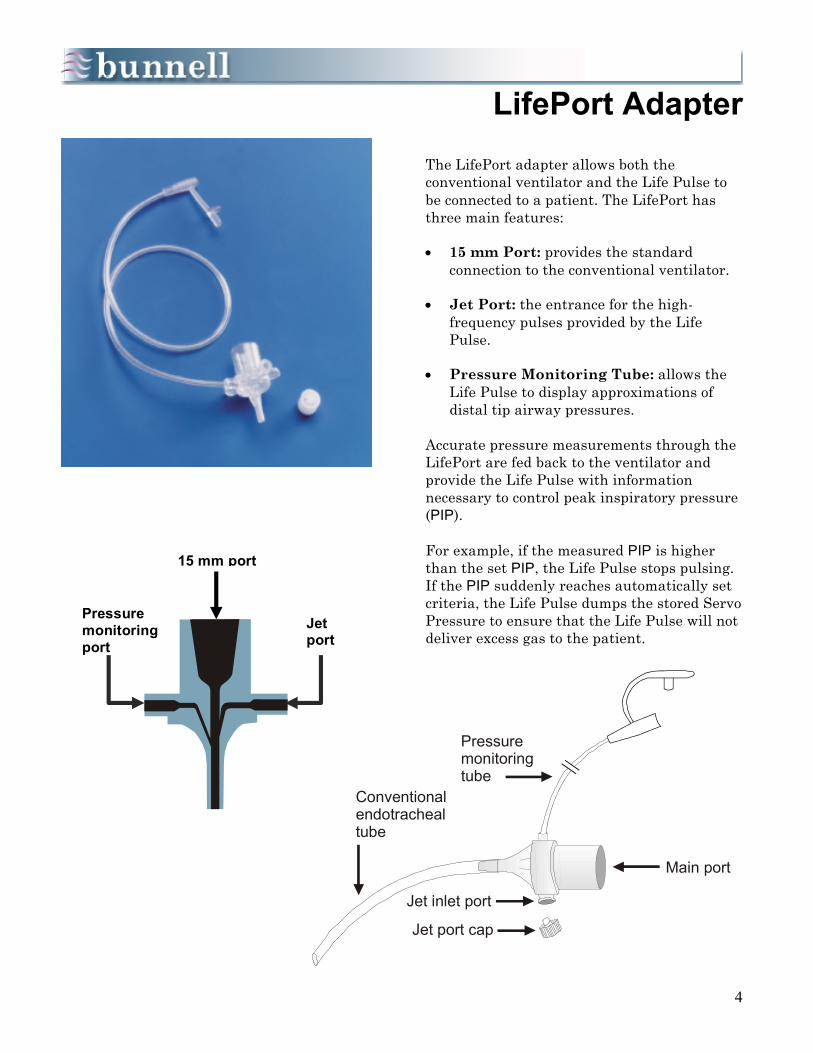
Jet inlet port
Jet port cap
Main port
Pressuremonitoringtube
Conventionalendotrachealtube
LifePort Adapter
The LifePort adapter allows both the conventional ventilator and the Life Pulse to be connected to a patient. The LifePort has three main features: • 15 mm Port: provides the standard
connection to the conventional ventilator. • Jet Port: the entrance for the high-
frequency pulses provided by the Life Pulse.
• Pressure Monitoring Tube: allows the
Life Pulse to display approximations of distal tip airway pressures.
Accurate pressure measurements through the LifePort are fed back to the ventilator and provide the Life Pulse with information necessary to control peak inspiratory pressure (PIP). For example, if the measured PIP is higher than the set PIP, the Life Pulse stops pulsing. If the PIP suddenly reaches automatically set criteria, the Life Pulse dumps the stored Servo Pressure to ensure that the Life Pulse will not deliver excess gas to the patient.
Pressure monitoring port
Jet port
15 mm port

5
Chapter 2 SETUP
The Life Pulse should be positioned so that the displays are easy to read and its controls and the conventional ventilator controls are within easy reach. The cart is on 5 inch, lockable casters for easy portability and stability. The Bunnell ventilator cart is designed to carry most of the patient’s cardiopulmonary equipment. For example, oxygen analyzers and other monitors can be placed on the top shelf. The Life Pulse is typically placed on the second shelf, the conventional ventilator on the third, and an uninterruptable power supply on the bottom. Setup procedures for the Life Pulse include making connections in three places: • the Rear Panel,
• the Front Panel, and
• the Patient Box.
Objectives 1. Understand the connections to the electrical power, air, oxygen, and water necessary for
the Life Pulse to function.
2. Know how to install the humidifier cartridge and circuit.

6
WITH INTERNAL HUMIDIFIER
LR 52321STANDARD C22-2 NO. 125
MODEL 203
SERIAL NO.
DO NOT BLOCK VENT HOLESALARMVOLUME
PATIENT BOX
+ +
+ +
+ +
OXYGENSENSOR
MIXED GASINPUT
GAS FLOWApprox. 0.1 LPM
+ +
ANALOGOUTPUT
DO NOT BLOCK
3 AMPS
HOURS
MANUFACTURED BYBUNNELL IncorporatedSal t Lake City, UT 84115
WARNING: Operate uni t on ly in accordance with manufacturer ’soperating manual. Do not remove cover -- -- possible electricshock hazard. Refer servicing to quali fied personnel.
DANGER: EXPLOSION HAZARD. DO NOTUSE IN THEPRESENCE OF FLAMMABLE ANAESTHETICS.
DANGER: RISQUE D’EXPLOSION NE PAS EMPLOYEREN PRESENCE D’ANESTHESIQUES INFLAMMABLES.
PATIENT NO. 4,481,944PATIENT NO. 4,501,405PATIENT NO. 4,538,604PATIENT NO. 4,588,425OTHER PATENTS PENDING
MADE IN U.S.A.
THIS EQUI PMEN T C OM PLI ES WITH REQU IREM ENTSIN PAR T IS O F FC C RU LES FO R A CL ASS OF C OM -PUTIN G D EVICE. OPER ATIO N O F TH IS EQ UIPM ENTIN A RESIDEN TI AL AREA M AY CAUSE U NACC EPTABLEIN TER FER ENCE TO RADIO AND TV RECEPTIO N RE-Q UIRI NG THE OPERATOR TO TAKE WHATEVER STEPSARE NECESSARY TO COR RECT THE I NTERFERENCE.
3.0 AMP
120 VAC
60 HZ
REAR PANEL CONNECTIONS 1. Plug in the power cord to a standard 110-
volt outlet or, preferably, an uninterruptible power supply.
2. Connect a high-pressure oxygen hose from a
low flow air/oxygen blender (0-30 L/min) or the output from the low flow port (2-100 L/min) of a standard blender to the Mixed Gas Input fitting. A minimum pressure of 30 psi is required to operate the Life Pulse.
3. Attach an oxygen analyzer to the Oxygen
Sensor to monitor FiO2 (not applicable to serial number 2414 or higher), or monitor FiO2 from the air/oxygen blender output.
4. With Model 203, plug in one of a variety of
recording devices to the Analog Output to monitor airway pressure graphically (Optional).
5. Connect the Patient Box to the ventilator by
its electrical cable attached to the multi-pinned connector.
6. Adjust the volume of the audible alarms
using the Alarm Volume dial.
CHECKLIST Rear Panel Connections
• Power cord • Gas in from blender • O2 Sensor (Only SN’s 2413 and lower) • Patient Box • Alarm volume
Life Pulse Model 203
Life Pulse Model 203 A
Mixed gas input
Patient Box connector
Alarm volume
Analog output
Power cord
Circuit breaker
Gas Dump port
O2 sensor

7
2
1
6 5 4
3
GAS OUT PURGE
Transfer tube towater supply
Cartridge in door
Green gas inlettube to Gas Out
Purge tube
Water inlettube
WaterPump
FRONT PANEL CONNECTIONS
1. Insert the Humidifier Cartridge into the
cartridge door. Latch the door shut to make all electrical connections between the cartridge and the Life Pulse.
2. Connect the green gas inlet tube to the
large barbed connector labeled GAS OUT. 3. Connect the small diameter purge tube to
the barbed connector labeled PURGE. 4. Locate the water inlet tube, a clear tube
running from the lower right corner of the cartridge with a check valve and a Leur fitting on the end.
5. Install the water inlet tube by placing the
clear tube into the pump housing, closing the pump door securely to pinch the water inlet tube inside, and connect the water transfer tube to the Luer connector on the end of the water inlet tube.
6. Tap the sterile water bag with the other
end of the water transfer tube and open the tubing clamp.
Use only sterile water for the cartridge water supply.
CHECKLIST
Front Panel Connections
1 Cartridge in and door latched
2 Green gas inlet tube
3 Purge tube
4 Water inlet tube
5 Water pump
6 Water supply bag
WARNING: The water inlet tube of the humidifier cartridge/circuit must be latched into the pump housing to prevent cartridge overfill and delivery of water to the patient by gravity feed.
WARNING: The water supply should be positioned at or below the level of the humidifier cartridge to decrease the potential of overfilling the cartridge by gravity feed.

8
PATIENT BOX CONNECTIONS
1. Locate the soft pinch tubing portion of the
circuit just beyond where the red and white wires inside the circuit terminate.
2. Place the pinch tubing in line with the
pinch valve assembly. 3. Hold the pinch tubing on each side of the
pinch valve assembly. 4. Press the PUSH TO LOAD button with one
finger. 5. Slide the pinch tubing into the pinch valve
assembly until you feel it snap into place. The illustrations on the left show a proper pinch tubing placement. The entire width of the pinch tube should be within the pinch valve jaws. 6. Connect the small purge tube to the
barbed connector labeled FROM PURGE. The disposable humidifier cartridge and circuit are now ready for operation, and the Life Pulse is ready to be turned on.
CHECKLIST Patient Box Connections
• Pinch tubing in pinch valve • Purge tube connect
Purge Tube
Push To Load button
To Patient
Pinch Tube
Pinch Valve
End view
9
SETUP CAUTIONS
Two cautions should be noted about the Setup procedure: First, patients are often placed on the Life Pulse on an emergency basis. You can save time if the ventilator is stored clean and partially set up, ready for use. Do NOT install the pinch tube in the pinch valve prior to actual patient set-up. The disposable cartridge/circuit, water transfer tube, and a test lung can be placed with the Life Pulse. If using the Bunnell Cart, everything necessary to begin high-frequency jet ventilation can be wheeled to the patient’s bedside. Second, notice that the installation description includes only cartridge/circuit tubing supplied by Bunnell Incorporated. Do NOT make modifications to the supplies or the setup procedure! Pressures cannot be monitored accurately and the Life Pulse will not work properly if other equipment is teed into the pressure monitoring tube or if leaks are present in the circuit.

10
Chapter 3 VENTILATOR CONTROLS &
TEST PROCEDURE
This section discusses how to manipulate the CONTROLS and perform a systems test. When the ON button is pressed, the Life Pulse activates into the Standby mode with an audible alarm sounding. The Standby mode is indicated by a small light in the corner of the STANDBY button and an audible alarm every 30 seconds. The alarm may be silenced by pushing the SILENCE button. Once the 60-second alarm silence time has expired, the audible alarm will sound 6 beeps every 30 seconds to remind you that the Life Pulse is in the Standby mode and not operating. The Life Pulse can monitor conventional ventilator and other high-frequency ventilator pressures in the Standby mode. This information will be displayed in the MONITOR section.
Objectives 1. Be able to attach the Life Pulse circuit to the LifePort adapter.
2. Understand the ON, STANDBY, ALARM SILENCE, TEST, and ENTER buttons.
3. Know how to perform a Life Pulse systems test and know the meaning of VENTILATOR FAULT alarms 02, 03, and 04.
4. Be able to enter NEW settings and convert them to NOW settings.
CONTROLS
ON
SILENCE
TEST
POWER ON
STANDBY
STANDBYENTER ENTER
SILENCEENTER
11
+
+
+
+
THE CONTROLS SECTION
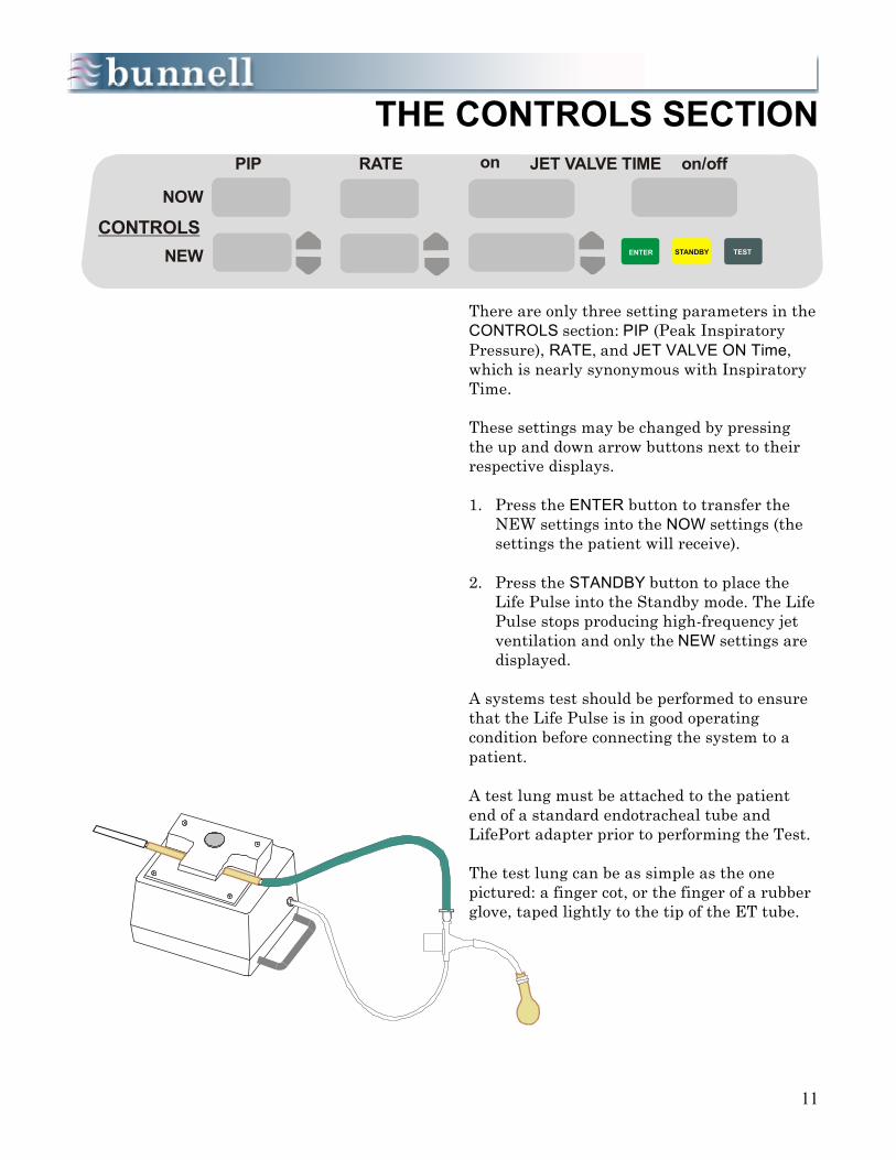
There are only three setting parameters in the CONTROLS section: PIP (Peak Inspiratory Pressure), RATE, and JET VALVE ON Time, which is nearly synonymous with Inspiratory Time. These settings may be changed by pressing the up and down arrow buttons next to their respective displays. 1. Press the ENTER button to transfer the
NEW settings into the NOW settings (the settings the patient will receive).
2. Press the STANDBY button to place the
Life Pulse into the Standby mode. The Life Pulse stops producing high-frequency jet ventilation and only the NEW settings are displayed.
A systems test should be performed to ensure that the Life Pulse is in good operating condition before connecting the system to a patient. A test lung must be attached to the patient end of a standard endotracheal tube and LifePort adapter prior to performing the Test. The test lung can be as simple as the one pictured: a finger cot, or the finger of a rubber glove, taped lightly to the tip of the ET tube.
RATE JET VALVE TIMEon on/offPIP
NOW
NEWCONTROLS
TESTSTANDBYENTER

12
TESTSTANDBY
JET VALVE TIMEon on/off
ENTER
seconds
PERFORMING A TEST
The Life Pulse’s systems test will ensure that the ventilator is operating according to specifications. To perform the test, follow these steps: 1. Attach a LifePort adapter to an ET tube and
test lung.
2. In the Standby mode, connect the patient end of the Life Pulse circuit, coming from the pinch valve, to the Jet port on the side of the LifePort adapter.
3. Connect the clear pressure monitoring tube of the LifePort adapter to the Patient Box barbed connector labeled MONITORING LUMEN.
4. Press the TEST button. An automatic test begins which determines the integrity of all the ventilator’s electronics and valves.
5. Observe the front panel to assure all LEDs and displays are functional, and listen to make sure the audible alarm is functioning properly. If no problems are detected, all the ventilator displays will illuminate 1 through 9 in sequence and all the alarm messages will be displayed.
The Test procedure will end with the Life Pulse in the Standby mode and an audible alarm sounding.
6. Silence the audible alarm by pressing the SILENCE button. The audible alarm stops for 60 seconds.
7. Once the internal Test passes, perform an operational test using the test lung. A conventional ventilator is not needed and the LifePort adapter 15mm connector is left open to the room.
8. Press the ENTER button to activate the default control settings (20, 420, 0.02).
9. Once the PIP is stable, the Ready light will activate. Make sure the pressures are stable and the PEEP is reading 0.0 ± 1 cm H2O.
10. If the PEEP is > ± 1 cm H2O, switch out the Patient Box and repeat the operational test.
A FAILED TEST
ALARMS
JET VALVE FAULT
LOW GAS PRESSCANNOT MEET PIP
LOSS OF PIPHIGH PIP
VENTILATOR FAULT
SILENCERESET
All possible alarms will be illuminated briefly during the systems test.
Press TEST button to begin systems test.
13
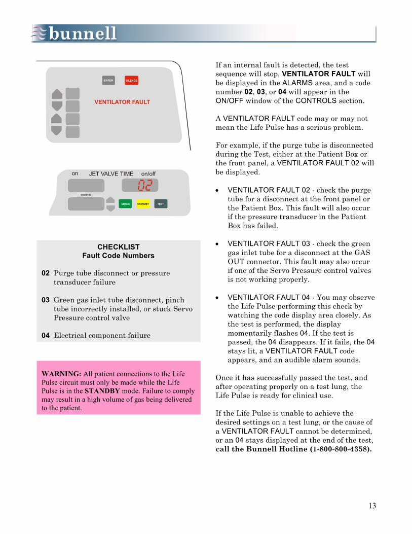
If an internal fault is detected, the test sequence will stop, VENTILATOR FAULT will be displayed in the ALARMS area, and a code number 02, 03, or 04 will appear in the ON/OFF window of the CONTROLS section. A VENTILATOR FAULT code may or may not mean the Life Pulse has a serious problem. For example, if the purge tube is disconnected during the Test, either at the Patient Box or the front panel, a VENTILATOR FAULT 02 will be displayed. • VENTILATOR FAULT 02 - check the purge
tube for a disconnect at the front panel or the Patient Box. This fault will also occur if the pressure transducer in the Patient Box has failed.
• VENTILATOR FAULT 03 - check the green
gas inlet tube for a disconnect at the GAS OUT connector. This fault may also occur if one of the Servo Pressure control valves is not working properly.
• VENTILATOR FAULT 04 - You may observe
the Life Pulse performing this check by watching the code display area closely. As the test is performed, the display momentarily flashes 04. If the test is passed, the 04 disappears. If it fails, the 04 stays lit, a VENTILATOR FAULT code appears, and an audible alarm sounds.
Once it has successfully passed the test, and after operating properly on a test lung, the Life Pulse is ready for clinical use. If the Life Pulse is unable to achieve the desired settings on a test lung, or the cause of a VENTILATOR FAULT cannot be determined, or an 04 stays displayed at the end of the test, call the Bunnell Hotline (1-800-800-4358).
SILENCEENTER
VENTILATOR FAULT
TESTSTANDBY
JET VALVE TIMEon on/off
ENTER
seconds
CHECKLIST Fault Code Numbers
02 Purge tube disconnect or pressure
transducer failure 03 Green gas inlet tube disconnect, pinch
tube incorrectly installed, or stuck Servo Pressure control valve
04 Electrical component failure
WARNING: All patient connections to the Life Pulse circuit must only be made while the Life Pulse is in the STANDBY mode. Failure to comply may result in a high volume of gas being delivered to the patient.

14
Chapter 4 PRESSURE MONITORING
The MONITOR displays reflect the pressures at the tip of the endotracheal tube and the internal Servo or drive pressure of the Life Pulse. If the Life Pulse is in Standby, and there is no patient connected to the Patient Box, the displays will all read zero. Once the pressure monitoring tube of the LifePort adapter has been connected to the Patient Box, the Life Pulse, even in its Standby mode, will begin to monitor the pressures being delivered by the conventional ventilator. These pressures are updated in the MONITOR displays every 10 seconds. The Life Pulse monitors:
• PIP: Peak Inspiratory Pressure,
• PEEP: Positive End-Expiratory Pressure,
• MAP: Mean Airway Pressure,
• DP: PIP minus PEEP, roughly equivalent to tidal volume, and
• SERVO PRESSURE: internal driving pressure; always 0.0 in Standby mode.
Objectives 1. Appreciate the advantages of the LifePort Adapter and the purpose of each of its 3 ports.
2. Understand the parameters displayed in the MONITOR section and where they are measured.
3. Understand Servo Pressure and its clinical relevance.
4. Understand the function of the PURGE.
PIP
P
PEEP
SERVOPRESS
MAP
cm H O2
cm H O
cm H O2 cm H O2
ON OFF
JET VALVE
MONITOR
PSI (0.145kPa)

15
MONITOR DISPLAYS
• PIP: the average of maximum airway
pressures measured during a set time period
• PEEP: the average minimum airway
pressure • MAP: is an average of pressures measured
from the total pressure waveform. It includes pressures produced by high-frequency ventilation, conventional ventilation, or spontaneous breathing.
• DP: (Delta P) simply the arithmetic
difference between PIP and PEEP. DP is roughly proportional to Tidal Volume and its importance in clinical decision making will become more apparent in the discussion of patient management.
• SERVO PRESSURE: the internal drive
pressure of the Life Pulse; indicates how much gas flow must be produced to meet the NOW PIP, Rate, and On-Time requested by the operator.
Servo Pressure is regulated by the ventilator’s microprocessor and is outside the control of the operator. Bigger patients, or those with more compliant lungs, will require higher Servo Pressures whereas those infants with smaller and/or less compliant lungs will require lower Servo Pressures. Servo Pressure is an indication of how much gas flow the Life Pulse must generate to meet the settings requested. Servo Pressure changes above or below the established operating level for a patient may be a result of changes in lung compliance, airway resistance, or lung volume. Servo Pressure changes give an early indication that the patient’s condition may be improving or worsening.
SERVO PRESSURE é • Improved compliance and/or resistance • Air leak • Disconnected tube SERVO PRESSURE ê • Worsening compliance and/or resistance • ET tube obstruction • Tension pneumothorax • Patient needs suctioning • Right mainstem intubation
PIP
SERVO PRESSURE
rP (i.e., VT)
MAP
PEEP
16
PRESSING ENTER BUTTON
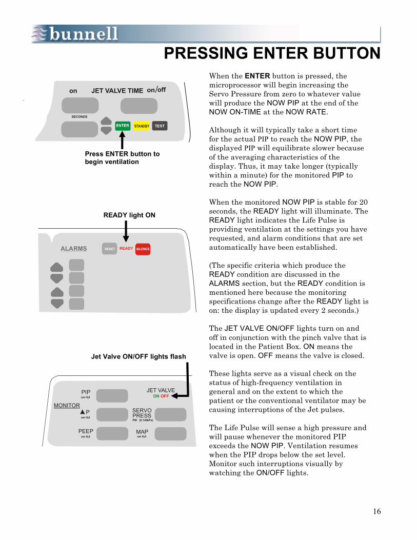
When the ENTER button is pressed, the microprocessor will begin increasing the Servo Pressure from zero to whatever value will produce the NOW PIP at the end of the NOW ON-TIME at the NOW RATE. Although it will typically take a short time for the actual PIP to reach the NOW PIP, the displayed PIP will equilibrate slower because of the averaging characteristics of the display. Thus, it may take longer (typically within a minute) for the monitored PIP to reach the NOW PIP. When the monitored NOW PIP is stable for 20 seconds, the READY light will illuminate. The READY light indicates the Life Pulse is providing ventilation at the settings you have requested, and alarm conditions that are set automatically have been established. (The specific criteria which produce the READY condition are discussed in the ALARMS section, but the READY condition is mentioned here because the monitoring specifications change after the READY light is on: the display is updated every 2 seconds.) The JET VALVE ON/OFF lights turn on and off in conjunction with the pinch valve that is located in the Patient Box. ON means the valve is open. OFF means the valve is closed. These lights serve as a visual check on the status of high-frequency ventilation in general and on the extent to which the patient or the conventional ventilator may be causing interruptions of the Jet pulses. The Life Pulse will sense a high pressure and will pause whenever the monitored PIP exceeds the NOW PIP. Ventilation resumes when the PIP drops below the set level. Monitor such interruptions visually by watching the ON/OFF lights.
ALARMS
SILENCERESET READY
cm H 02
PIPcm H 02
Pcm H 02
cm H 02
PEEP
SERVOPRESSPSI (0.145kPa)
MAP
MONITOR
JET VALVEON OFF
JET VALVE TIME on on off
Press ENTER button to begin ventilation
READY light ON
Jet Valve ON/OFF lights flash

17
PURGE PAUSES
The Life Pulse may pause periodically and briefly during operation for no apparent reason. Such pauses can occur during clinical use or when you are operating on a test lung. These brief pauses are usually a result of the purge of the pressure monitoring tube that takes place once every 15 seconds. The Purge valve is located next to the pressure transducer inside the Patient Box. When the valve opens it allows a pulse of dry air to flush the pressure monitoring tube. On rare occasions, the purge may cause high pressure to be measured by the transducer that, in turn, makes the Life Pulse skip a beat in conjunction with its built-in response to high pressures. Do not be concerned if the Life Pulse appears to hiccup every occasionally. If you time the pauses, you will find that they occur at some multiple of 15 seconds. (This pause usually will only occur on rates of 550 bpm or greater.)
cm H 02
PIPcm H 02
Pcm H 02
cm H 02
PEEP
SERVOPRESSPSI (0.145kPa)
MAP
MONITOR
JET VALVEON
Extended pauses of the Green Jet Valve ON light indicate an interruption of jet pulses

18
Chapter 5 HUMIDIFIER
The Life Pulse humidifier uses a one-piece disposable cartridge and tubing set called the humidifier cartridge/circuit. This item is often referred to as “the cartridge”, “the circuit”, or “the patient breathing circuit”. All are terms that refer to all or part of the humidifier cartridge/circuit. It is pre-assembled and contains the heating wire, thermistors, and all connections needed for operation. Gas from the GAS OUT connector on the front panel of the ventilator flows into the humidifier cartridge via the green gas inlet tube. The shorter clear tube is the water inlet tube and contains a check valve that prevents gas from leaking out when the water supply bag is disconnected. Water is pumped into the cartridge against the cartridge pressure. Once the water inlet tubing is securely closed in the pump housing, water and air cannot be forced back into the water supply bag.
Objectives 1. Describe the flow of gas from the ventilator through the entire length of the Humidifier
Cartridge/Circuit. 2. Understand the purpose of humidification and how it is produced and regulated. 3. Learn to adjust the temperature manually in the cartridge and the circuit. 4. Understand the function of the pinch tube portion of the circuit.
Purge tube
Circuit
Heating WireCircuit thermistor
Purge tube
Pinch Tube
Gas inlettube
Cartridgethermistor
Gas topatient
Cartridge
Water supply tube
19
GAS FLOW THROUGH HUMIDIFIER
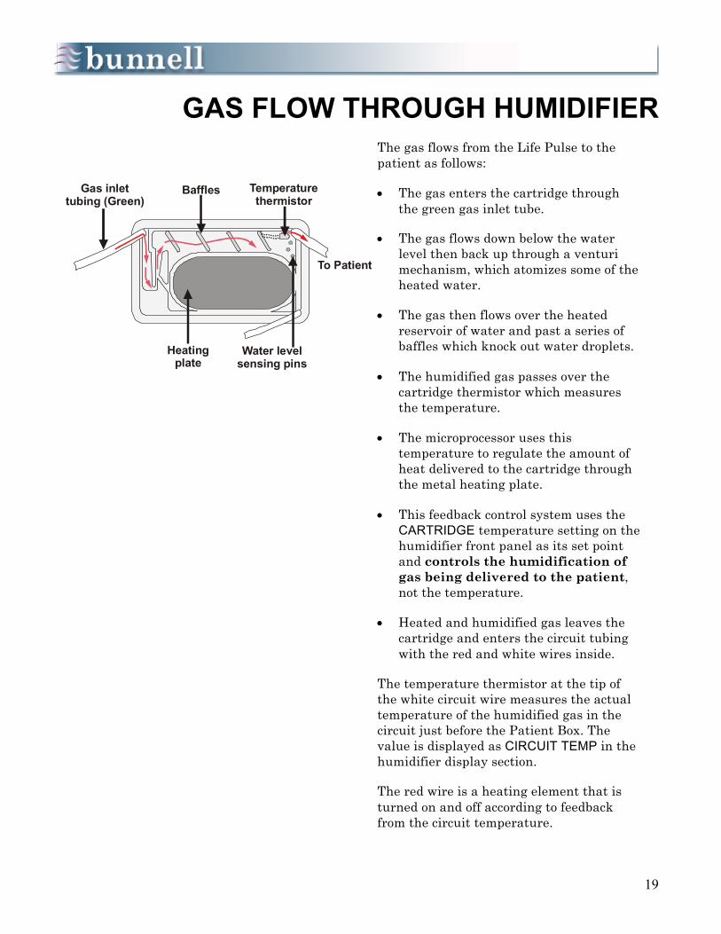
The gas flows from the Life Pulse to the patient as follows: • The gas enters the cartridge through
the green gas inlet tube. • The gas flows down below the water
level then back up through a venturi mechanism, which atomizes some of the heated water.
• The gas then flows over the heated
reservoir of water and past a series of baffles which knock out water droplets.
• The humidified gas passes over the
cartridge thermistor which measures the temperature.
• The microprocessor uses this
temperature to regulate the amount of heat delivered to the cartridge through the metal heating plate.
• This feedback control system uses the
CARTRIDGE temperature setting on the humidifier front panel as its set point and controls the humidification of gas being delivered to the patient, not the temperature.
• Heated and humidified gas leaves the
cartridge and enters the circuit tubing with the red and white wires inside.
The temperature thermistor at the tip of the white circuit wire measures the actual temperature of the humidified gas in the circuit just before the Patient Box. The value is displayed as CIRCUIT TEMP in the humidifier display section. The red wire is a heating element that is turned on and off according to feedback from the circuit temperature.
Gas inlettubing (Green)
Baffles Temperaturethermistor
Water levelsensing pins
Heatingplate
To Patient

20
GAS FLOW THROUGH HUMIDIFIER (cont.)
• Using the CIRCUIT temperature setting
on the humidifier front panel as its set point, the microprocessor controls the temperature of the gas being delivered to the patient.
The heating wire also minimizes the amount of condensation in the tubing to control “rainout.” • The heated and humidified gas flows into
the pinch tube section of the circuit where the pinch valve breaks the flow into breaths.
• The gas begins to cool as it leaves the
pinch valve and condensation occurs as a result of the cooling.
The temperature of the gas that enters the LifePort adapter will be approximately 3o C less than when it was last measured by the circuit thermistor. Therefore, the CIRCUIT temperature is automatically set at 40o C on the front panel by the microprocessor. The intention is to deliver the gas to the patient at close to 37o C, normal body temperature.
Pinch Tube
Pinch Valve

21
PURGE
ENTER
GAS OUT
HUMIDIFIER
WAIT
STARTING THE HUMIDIFIER
The Life Pulse Humidifier requires little operator intervention. The temperature of the gas is regulated by feedback control from the point where it enters the cartridge to the point where it enters the Patient Box. When the Life Pulse is first turned on, the ventilator comes up in its Standby mode and the humidifier is in its WAIT mode. The two modes are equivalent; there is no ventilation and no humidification or heating being done in these modes. When the ENTER button is pressed, the light in the corner of the WAIT button goes off and the humidifier automatically begins functioning. The pump has 86 seconds to fill the cartridge to the proper level. When the STANDBY button is pressed, the light in the corner of the WAIT button is lit and the humidifier assumes its WAIT mode. The humidifier WAIT mode may also be entered independently by pressing the WAIT button. In this case, the light in the corner of the WAIT button begins blinking on and off. Press the WAIT button again to bring the humidifier back into operation and reset the 86-second timer for the water pump,
Press WAIT button to stop and start humidification
Press ENTER button to initially start humidifier
22
CHANGING THE CIRCUIT
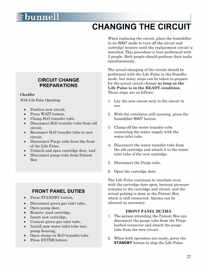
When replacing the circuit, place the humidifier in its WAIT mode to turn off the circuit and cartridge heaters until the replacement circuit is installed. This procedure is best performed with 2 people. Both people should perform their tasks simultaneously. The actual changing of the circuit should be performed with the Life Pulse in the Standby mode, but many steps can be taken to prepare for the actual circuit change as long as the Life Pulse is in the READY condition. These steps are as follows: 1. Lay the new circuit next to the circuit in
use. 2. With the ventilator still running, press the
humidifier WAIT button. 3. Clamp off the water transfer tube
connecting the water supply with the water inlet tube.
4. Disconnect the water transfer tube from
the old cartridge and attach it to the water inlet tube of the new cartridge.
5. Disconnect the Purge tube. 6. Open the cartridge door. The Life Pulse continues to ventilate even with the cartridge door open, because pressure remains in the cartridge and circuit, and the actual pulsing is done in the Patient Box, which is still connected. Alarms can be silenced as necessary.
FRONT PANEL DUTIES 1. The person attending the Patient Box can
disconnect the purge tube from the Purge barbed connector and attach the purge tube from the new circuit.
2. When both operators are ready, press the
STANDBY button to stop the Life Pulse.
CIRCUIT CHANGE PREPARATIONS
Checklist With Life Pulse Operating:
• Position new circuit, • Press WAIT button, • Clamp H2O transfer tube, • Disconnect H2O transfer tube from old
circuit, • Reconnect H2O transfer tube to new
circuit, • Disconnect Purge tube from the front
of the Life Pulse, • Unlatch and open cartridge door, and • Disconnect purge tube from Patient
Box.
FRONT PANEL DUTIES • Press STANDBY button, • Disconnect green gas inlet tube, • Open pump door, • Remove used cartridge, • Insert new cartridge, • Connect green gas inlet tube, • Install new water inlet tube into
pump housing, • Open clamp on H2O transfer tube • Press ENTER button.

23
CHANGING THE CIRCUIT (cont.)
Once the Life Pulse has been placed in the Standby mode, manually ventilate the patient or adjust the conventional ventilator settings to provide the patient with adequate ventilatory support while the Life Pulse is not running. With two people, one at the ventilator and one at the Patient Box, the circuit change can be performed more quickly.
PATIENT BOX DUTIES
1. The person at the Patient Box disconnects
the Jet port of the old Life Pulse circuit from the side of the LifePort adapter.
2. Remove the old pinch tube from the jaws of
the pinch valve in the Patient Box and install the pinch tube of the new circuit.
3. Attach the new circuit to the Jet port of the
LifePort adapter.
FRONT PANEL DUTIES 1. The person at the ventilator can disconnect
the gas inlet tube and remove the cartridge from its holder,
2. Place the new cartridge into the cartridge
door and latch it, 3. Connect the green GAS OUT tube and
purge tube to their ports, 4. Install the water inlet tube into the pump
housing and latch the door securely; with the pump door latched open the clamp on the water transfer tube.
5. Press the ENTER button to reestablish
high-frequency ventilation and clear a LOSS OF PIP alarm that may result from tubing disconnections.
PATIENT BOX DUTIES • Disconnect Life Pulse circuit at ET
tube connections, • Remove pinch tube from pinch valve, • Insert new pinch tube into pinch
valve, • Connect new Life Pulse circuit at ET
tube connections, and • Press ENTER button to resume
ventilation.
POST-CIRCUIT CHANGE
After ENTER button is pressed: • Close and latch cartridge door, • Reconnect purge tube at Life Pulse
front panel, • Reconnect purge tube at Patient Box, • Make sure Humidifier is not in WAIT
mode, • Recheck all connections, and • Press ENTER button again if
necessary.

24
CHANGING THE CIRCUIT (cont.)
6. After the ventilator is running, make sure
the purge tube is attached at both the ventilator and Patient Box barbed connectors.
7. If necessary, adjust the conventional
ventilator settings back to their previous settings. Lower the peak pressure first to eliminate any unintentional interruptions of the jet pulses, then lower the CV rate back to where it was before the circuit change.
8. Bring the humidifier out of its Wait mode
by pressing the WAIT button after the Life Pulse has been restarted with the new cartridge/circuit; otherwise, the patient will receive relatively cold and dry gas.
There are no alarms for low temperature or low water level when the humidifier is in the Wait mode. The circuit change is not complete until the water fills the cartridge, the water pump shuts off, and humidity appears in green portion of the circuit between the Patient Box and the LifePort. On rare occasions, a defective cartridge might not fill, might overfill, or might not heat properly. The circuit will then need to be replaced.
IMPORTANT
To complete a circuit change:
• Observe water filling cartridge,
• Observe water pump stopping when cartridge fills to proper level, and
• Observe humidity appearing in the green portion of the circuit.
25
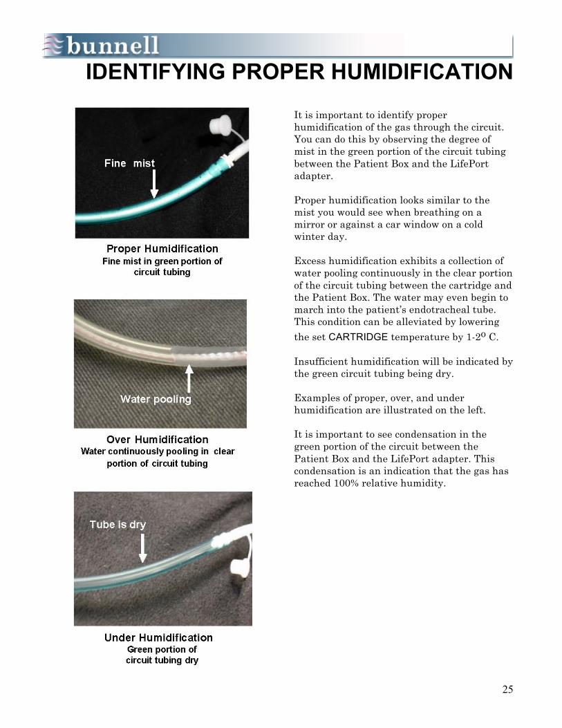
IDENTIFYING PROPER HUMIDIFICATION
It is important to identify proper humidification of the gas through the circuit. You can do this by observing the degree of mist in the green portion of the circuit tubing between the Patient Box and the LifePort adapter. Proper humidification looks similar to the mist you would see when breathing on a mirror or against a car window on a cold winter day. Excess humidification exhibits a collection of water pooling continuously in the clear portion of the circuit tubing between the cartridge and the Patient Box. The water may even begin to march into the patient’s endotracheal tube. This condition can be alleviated by lowering the set CARTRIDGE temperature by 1-2o C. Insufficient humidification will be indicated by the green circuit tubing being dry. Examples of proper, over, and under humidification are illustrated on the left. It is important to see condensation in the green portion of the circuit between the Patient Box and the LifePort adapter. This condensation is an indication that the gas has reached 100% relative humidity.
26
Chapter 6 START UP
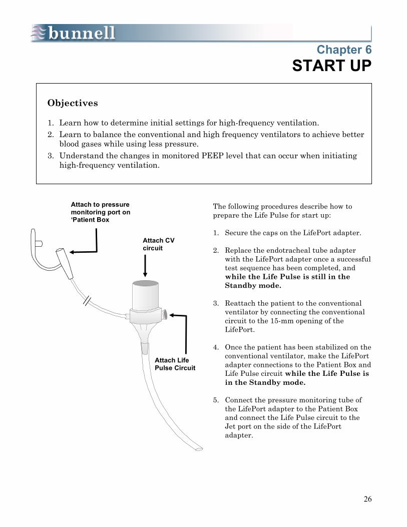
The following procedures describe how to prepare the Life Pulse for start up: 1. Secure the caps on the LifePort adapter. 2. Replace the endotracheal tube adapter
with the LifePort adapter once a successful test sequence has been completed, and while the Life Pulse is still in the Standby mode.
3. Reattach the patient to the conventional
ventilator by connecting the conventional circuit to the 15-mm opening of the LifePort.
4. Once the patient has been stabilized on the
conventional ventilator, make the LifePort adapter connections to the Patient Box and Life Pulse circuit while the Life Pulse is in the Standby mode.
5. Connect the pressure monitoring tube of
the LifePort adapter to the Patient Box and connect the Life Pulse circuit to the Jet port on the side of the LifePort adapter.
Objectives 1. Learn how to determine initial settings for high-frequency ventilation. 2. Learn to balance the conventional and high frequency ventilators to achieve better
blood gases while using less pressure. 3. Understand the changes in monitored PEEP level that can occur when initiating
high-frequency ventilation.
Attach to pressure monitoring port on ‘Patient Box
Attach CV circuit
Attach Life Pulse Circuit

27
MEASURING & DISPLAYING PRESSURES
Once the pressure monitoring tube of the LifePort adapter has been connected to the Patient Box, the Life Pulse, in its Standby mode, will begin to monitor the pressures being delivered by the conventional ventilator or other high frequency ventilator and update them in the MONITOR section every 10 seconds. It will take about a minute and a half for the MONITOR to display an accurate PIP, PEEP, and MAP being delivered by the conventional ventilator or HFOV. In the Standby mode, the Life Pulse monitors and displays the airway pressures as if measured at the distal tip of the ET tube. These pressures may or may not be different from the pressures displayed on the conventional ventilator. Remember that the conventional ventilator displays pressures measured proximally while the Life Pulse displays approximations of distal pressures. We recommend that start up decisions be based on the pressures displayed in the Life Pulse’s MONITOR section.
10 sec. 2nd 80 sec.
display
1st 80 sec. display

28
CHOOSING STARTING VALUES
The PIP setting chosen for initiation of high-frequency ventilation will depend on the PIP currently being monitored by the Life Pulse in its Standby mode. The other initial high-frequency settings are usually left at the default values of a RATE of 420 breaths per minute and an ON Time of 0.02 seconds. For larger patients, the rate may need to be lowered to avoid gas trapping and inadvertent PEEP (240-360 bpm). Generally, the more pulmonary airleaks are a concern, the lower you will set the background CV rate, PIP, and I-Time on the conventional ventilator. In fact, the goal is to effectively treat the patient in CPAP mode. PEEP and CPAP are a better methods than IMV breaths for controlling oxygenation in patients with airleaks. The more atelectasis is a concern, the higher the background CV Rate, PEEP, and I-Time can be set. Backgrounds CV rates greater than 5 bpm are almost never indicated. Consider background breaths a temporary recruitment maneuver while you find optimal PEEP. For more detailed information on choosing starting values, see the next few pages.
29
6 STEPS TO START HFV
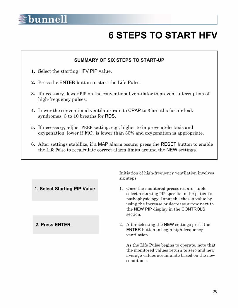
Initiation of high-frequency ventilation involves six steps: 1. Once the monitored pressures are stable,
select a starting PIP specific to the patient’s pathophysiology. Input the chosen value by using the increase or decrease arrow next to the NEW PIP display in the CONTROLS section.
2. After selecting the NEW settings press the
ENTER button to begin high-frequency ventilation.
As the Life Pulse begins to operate, note that the monitored values return to zero and new average values accumulate based on the new conditions.
SUMMARY OF SIX STEPS TO START-UP
1. Select the starting HFV PIP value. 2. Press the ENTER button to start the Life Pulse. 3. If necessary, lower PIP on the conventional ventilator to prevent interruption of
high-frequency pulses. 4. Lower the conventional ventilator rate to CPAP to 3 breaths for air leak
syndromes, 3 to 10 breaths for RDS. 5. If necessary, adjust PEEP setting: e.g., higher to improve atelectasis and
oxygenation, lower if FiO2 is lower than 30% and oxygenation is appropriate. 6. After settings stabilize, if a MAP alarm occurs, press the RESET button to enable
the Life Pulse to recalculate correct alarm limits around the NEW settings.
1. Select Starting PIP Value
2. Press ENTER

30
6 STEPS TO START HFV (cont.)
The Life Pulse may pause every time the conventional ventilator delivers a breath. These interruptions may be heard, or seen by observing the JET VALVE ON/OFF lights. The interruptions in the Jet pulses are caused by the delivery of conventional breaths at pressures higher than the PIP that has been requested by the operator and entered as the NOW PIP. Except in cases of extremely poor lung compliance, it is usually best to allow the high-frequency pulses to continue uninter-rupted by lowering the conventional PIP. 3. If desired, lower the conventional PIP by
slowly turning down the PIP knob to just below the threshold of interruptions; it may need to be lowered even more when treating infants with pulmonary airleaks.
4. Lower the rate of the conventional
ventilator to 0 -5 breaths per minute once the conventional PIP is set properly.
A conventional ventilator rate of zero (CPAP) to 2 breaths per minute may be used in cases of pulmonary air leak. If oxygenation is still a concern after optimizing PEEP, provide ample opportunity for the recruitment of collapsed alveoli by adjusting CV PIP, I-TIME, or by providing up to 6 conventional breaths per minute. Lower the CV support (e.g., lower the rate to 0-2 bpm) once collapsed alveoli are recruited and stabilized with adequate PEEP. If both problems are of equal concern after PEEP has been optimized, start with the lowest number of CV breaths possible and modest CV PIP and I-TIME settings.
3. Lower Conventional PIP
4. Lower Conventional Rate
31
5. Readjust PEEP
6. Press RESET
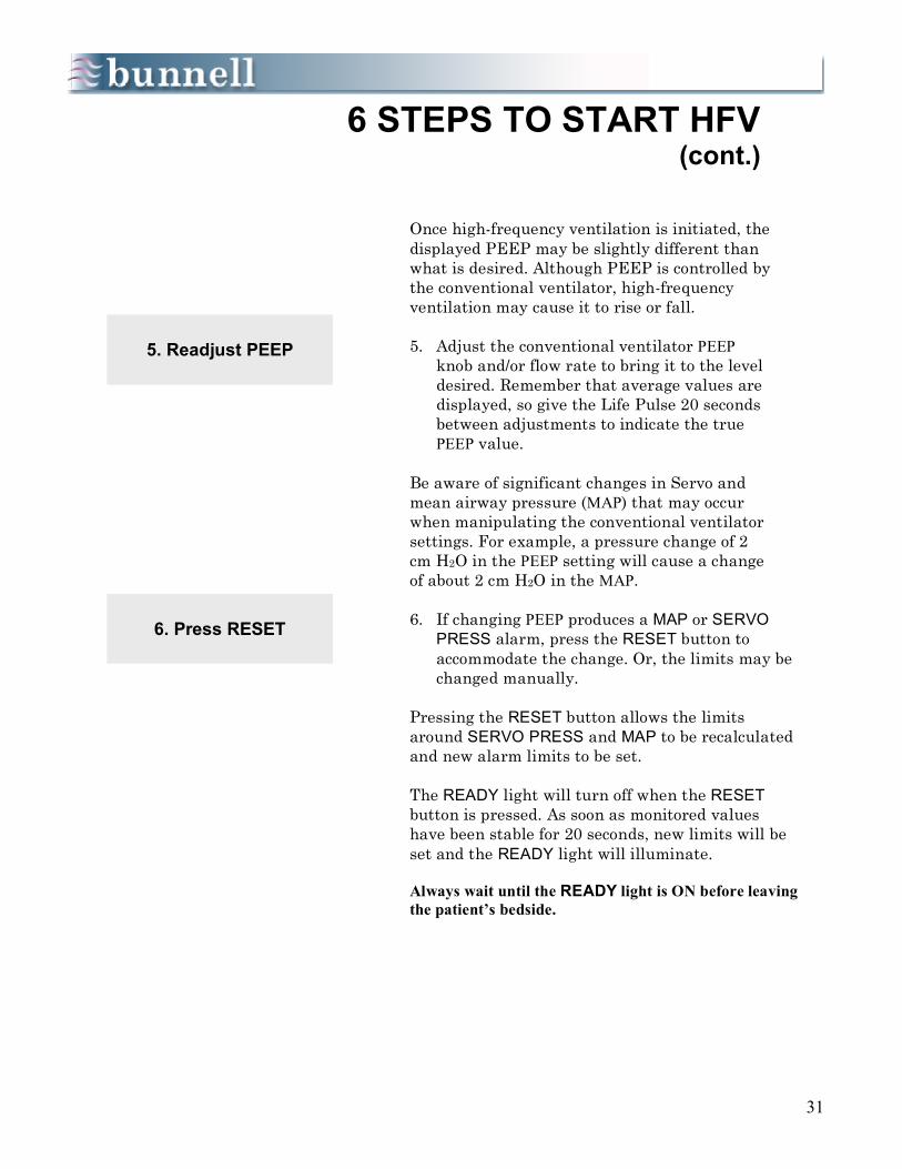
Once high-frequency ventilation is initiated, the displayed PEEP may be slightly different than what is desired. Although PEEP is controlled by the conventional ventilator, high-frequency ventilation may cause it to rise or fall. 5. Adjust the conventional ventilator PEEP
knob and/or flow rate to bring it to the level desired. Remember that average values are displayed, so give the Life Pulse 20 seconds between adjustments to indicate the true PEEP value.
Be aware of significant changes in Servo and mean airway pressure (MAP) that may occur when manipulating the conventional ventilator settings. For example, a pressure change of 2 cm H2O in the PEEP setting will cause a change of about 2 cm H2O in the MAP. 6. If changing PEEP produces a MAP or SERVO
PRESS alarm, press the RESET button to accommodate the change. Or, the limits may be changed manually.
Pressing the RESET button allows the limits around SERVO PRESS and MAP to be recalculated and new alarm limits to be set. The READY light will turn off when the RESET button is pressed. As soon as monitored values have been stable for 20 seconds, new limits will be set and the READY light will illuminate. Always wait until the READY light is ON before leaving the patient’s bedside.
6 STEPS TO START HFV (cont.)

32
Chapter 7 PATIENT MANAGEMENT
Managing patients on high-frequency ventilation is similar to managing patients on a conventional ventilator. The main distinction with the Life Pulse is that typically less pressure and much smaller tidal volumes are used to manage the patient. The conventional ventilator settings will be manipulated most often when oxygenation of the patient is of primary concern. The Life Pulse settings will be manipulated most often when ventilation (CO2 removal) and/or the consequences of using high airway pressures (e.g., pulmonary air leaks) are of greatest concern.
Objectives 1. Understand the advantages for patient management of using a conventional
ventilator in tandem with the high-frequency ventilator. 2. Understand the techniques for improving oxygenation and ventilation. 3. Comprehend the relationship between DP and tidal volume.

33
OXYGENATION
The main choices for improving oxygenation require increasing mean airway pressure by elevating the:
• CV PEEP • CV RATE • CV PIP • CV I-Time
High-frequency PIP and rate would be secondary considerations. Raising high-frequency On-Time has been shown to be more effective for improving ventilation than oxygenation. The choices for improving oxygenation due to atelectasis are: • Increases in PEEP are meant to
stabilize alveoli. PEEP changes are made with the conventional ventilator since the Life Pulse has no PEEP control. However, the PEEP adjustment will be displayed on the Life Pulse in the MONITOR, PEEP display. • Increase background rate from the
conventional ventilator. Do not exceed 6 bpm on the background rate. If more CV breaths are needed to oxygenate, it may be an indication that the PEEP is too low.
Always optimize PEEP before increasing CV Rate, PIP, or I-time. • Increase the PIP delivered with the
background conventional breaths. Increases in CV PIP are meant to reach the critical opening pressure required to inflate collapsed alveoli.
Adequate PEEP levels are essential for avoiding derecruitment between conventional breaths.
1. Increase PEEP
2. Increase CV Rate
3. Increase CV PIP

34
OXYGENATION (cont.)
• Increase I-Time, in combination with
adequate levels of PEEP and PIP, to improve atelectasis.
Consider carefully the combined effect of PIP and I-Time increases. Increasing I-Time when CV PIP is set at high levels increases the risks of causing lung injury. • If other approaches to oxygenation have
failed or are contrary to the patient’s pathophysiology, increase the Life Pulse PIP by 2 cm H2O at a time until the desired response has been achieved.
Increasing HFV PIP too high may result in hyperventilation and hypocarbia which, in preterm infants may increase the risk of cerebral injuries. Concomitant increases in PEEP may help maintain an appropriate tidal volume and reduce this risk. • If necessary, the conventional ventilator
PIP can be increased along with the Life Pulse peak pressure except in severe cases of air leak. However, the CV PIP should not be raised if it is at an adequate level to reach the critical opening pressure of the alveoli.
Remember to keep the conventional PIP below the Life Pulse’s peak pressure to avoid interrupting the high-frequency pulses. Additional possibilities for increasing mean airway pressure are available, but they have not been studied in prospective clinical trials. Increasing high-frequency rate by 50 or 60 breaths per minute at a time has been helpful in some cases, especially in smaller infants. If the high-frequency rate is increased, be sure to watch the PEEP level. Inadvertent PEEP may develop as the I:E ratio is shortened.
4. Increase CV I-Time
35
OXYGENATION Overexpanded Lungs
There is one major exception to this strategy. This exception arises when the patient on conventional ventilation has grossly overexpanded lungs. If overexpansion is observed on X-ray, the lungs will need to deflate considerably before any improvements in oxygenation will result. To accomplish this deflation, set the conventional ventilator rate near zero when starting the Life Pulse. In most cases, DO NOT DECREASE PEEP. Overexpanded lungs are usually a result of gas trapping, not excessive PEEP. Decreasing CV support (Rate, PIP, and I-Time) is usually a more effective strategy. PEEP must be maintained, or even increased, when the CV rate is very low to prevent atelectasis and maintain oxygenation. However, beware that if the patient initially responds well to this strategy, poor oxygenation may result some time later due to atelectasis. You must be ready to treat that condition as outlined above. A strategy for identifying optimal PEEP is demonstrated in the flow chart on the next page. It is always important to optimize PEEP regardless of what pathophysiology is being treated.
EXCEPTION!
Overexpanded Lungs
36
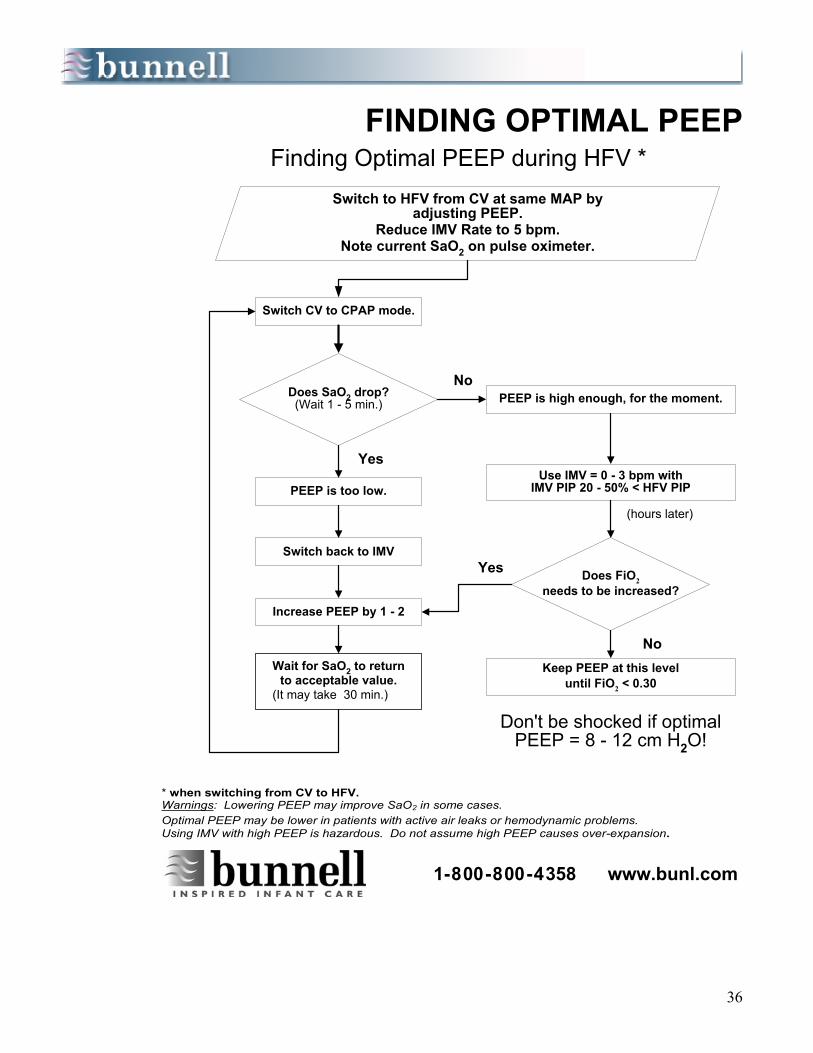
FINDING OPTIMAL PEEP
Switch to HFV from CV at same MAP byadjusting PEEP.
Reduce IMV Rate to 5 bpm.Note current SaO2 on pulse oximeter.
Finding Optimal PEEP during HFV *
Switch CV to CPAP mode.
Does SaO2 drop?(Wait 1 - 5 min.)
PEEP is too low.
Switch back to IMV
Increase PEEP by 1 - 2
Wait for SaO2 to returnto acceptable value.
(It may take 30 min.)
PEEP is high enough, for the moment.
(hours later)
Use IMV = 0 - 3 bpm withIMV PIP 20 - 50% < HFV PIP
Does FiO2needs to be increased?
Keep PEEP at this leveluntil FiO2 < 0.30
Don't be shocked if optimalPEEP = 8 - 12 cm H2O!
1-800-800-4358 www.bunl.com
* when switching from CV to HFV. Warnings: Lowering PEEP may improve SaO2 in some cases. Optimal PEEP may be lower in patients with active air leaks or hemodynamic problems. Using IMV with high PEEP is hazardous. Do not assume high PEEP causes over-expansion.
Yes
No
No
Yes
02559-00.1C
37
VENTILATION
Manipulating the patient’s arterial PCO2 is one of the easier tasks when using the Life Pulse. Studies have shown that ventilation (CO2 elimination) during high-frequency ventilation is proportional to the tidal volume squared ( VT
2 ). Tidal volume on the Life Pulse is roughly proportional to delta P (DP), the arithmetic difference between PIP and PEEP. Thus, small changes in PIP or PEEP can produce significant changes in a patient’s PCO2. The main choices for improving ventilation require increasing minute ventilation by changing: • HFV PIP • PEEP • HFV Rate
• If the patient’s PO2 is acceptable, but his
PCO2 is too high, increase high-frequency PIP by 1 to 2 cm H2O at a time.
• If the patient’s PO2 and PCO2 are both
unacceptable, increasing PIP may address both problems at once.
When PEEP is increased, oxygenation may improve. However, increasing PEEP without a corresponding increase in HFV PIP reduces tidal volume and may result in some degree of CO2 retention. The PIP must be increased by an equal amount to keep the delta P (DP) the same and maintain tidal volume and adequate ventilation.
1. Increase HFV PIP
38
VENTILATION (cont.)
• If the primary concern is air leaks or
cardiac compromise and oxygenation is acceptable, lower PEEP to increase ΔP (i.e., tidal volume) and increase ventilation.
Be careful not to compromise oxygenation when lowering PEEP. • Increase the high-frequency rate by 40 to
80 breaths per minute at a time to improve ventilation without further increasing PIP.
Increasing high-frequency rate is much less effective than increasing delta P (ΔP) for reducing PCO2 . Changes in CV Rate, PIP, and, to a lesser degree, I-Time may also effect HFV minute ventilation. Raising CV Rate or PIP seldom improves ventilation, but it may be helpful in extreme cases if HFV is not interrupted. • The main choices for raising PCO2 are, of
course, doing the opposite of the above suggestions for lowering PCO2 .
Decreasing HFV PIP is the most effective way to increase PCO2 . However, the concomitant drop in mean airway pressure may cause PO2 to fall. Thus, it is very important to raise PEEP in such cases to maintain adequate mean airway pressure. Reducing HFV Rate will also increase PCO2 unless inadvertent PEEP is present. If monitored PEEP falls when HFV Rate is dropped, PEEP may need to be increased to maintain adequate oxygenation. Do not hesitate to use the minimum Life Pulse HFV Rate of 240 bpm when indicated for hyperinflation. The Life Pulse can provide adequate ventilation over its entire range of HFV Rates (240 - 660 bpm).
2. Decrease PEEP
3. Increase HFV Rate
4. Hyperventilation
39
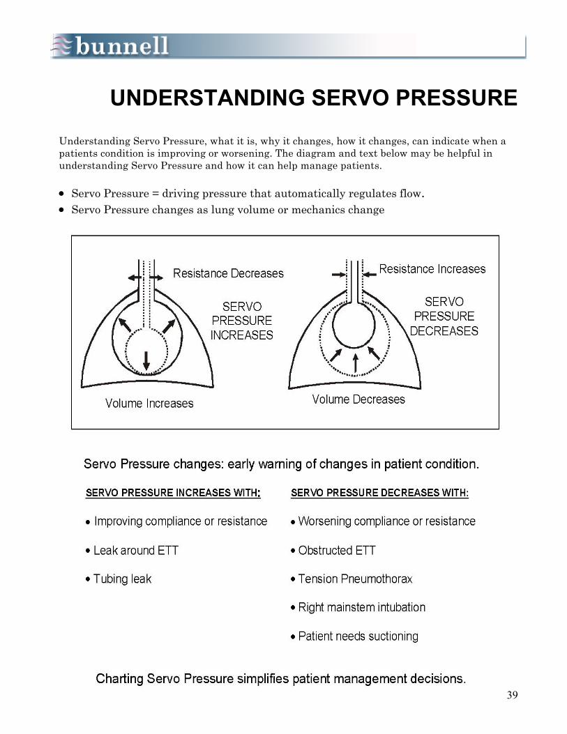
UNDERSTANDING SERVO PRESSURE
Understanding Servo Pressure, what it is, why it changes, how it changes, can indicate when a patients condition is improving or worsening. The diagram and text below may be helpful in understanding Servo Pressure and how it can help manage patients. • Servo Pressure = driving pressure that automatically regulates flow. • Servo Pressure changes as lung volume or mechanics change

40
Chapter 8
SUCTIONING THE PATIENT
High-frequency ventilation may mobilize and help remove secretions. Be prepared to suction soon after starting the Life Pulse on a patient. Suctioning may need to be performed more frequently in the first 4 to 6 hours. Suctioning frequency may then subside. Suctioning the patient is easy to learn because the procedure is similar to suctioning during conventional ventilation.
1. Suction according to hospital policy and procedures.
2. Make sure the monitored pressures are stable and the READY light is on before leaving the patient’s bedside.
Please call the Bunnell Hotline if you have questions about suctioning. 800-800-4358
SUCTIONING
Technique
Suction according to hospital policy and procedures.
Objectives 1. Learn the method of suctioning a patient while on high-frequency ventilation. 2. Be ready for problems that may possibly be encountered.
41
Chapter 9 WEANING
As the patient improves, he will eventually need to be weaned from the Life Pulse. The goal in most cases will be to wean the patient back to conventional ventilation at much less support than the patient was on before beginning high-frequency ventilation. However, the Life Pulse may be left on the patient while he is weaned directly to CPAP, a nasal cannula, or Nasal CPAP. Below is a summary of weaning guidelines:
Objectives: 1. Recognize the indications for weaning from the Life Pulse. 2. Know the various options for weaning and the advantages of each.
GENERAL GUIDELINES FOR WEANING • Decrease Minute Ventilation and MAP slowly by lowering PIP on the Life Pulse
and the conventional ventilator.
• Lower FIO2 gradually to around 30%.
• Continue decreasing PIP as blood gases allow, weaning slowly (1-2 cm H2O of PIP), unless hyperventilation is occurring, in which case PIP should be weaned faster.
• As the PIP is lowered into the teens, make sure if you are delivering conventional
ventilator breaths not let them interrupt the high-frequency pulses.
• As the high-frequency PIP continues to be decreased, consider extubating to Nasal CPAP near the level of the last recorded MAP.
• Place the Life Pulse into the Standby mode and begin Nasal CPAP.

42
WEANING (cont.)
• Wean slowly: The fundamental rule in
weaning is to WEAN SLOWLY, to wean as slowly as the patient allows. The Life Pulse is a very gentle form of ventilation, much more so than conventional ventilation. Therefore, weaning a patient back to conventional ventilation too soon is ill-advised.
• Find Optimal MAP: During patient
management, the MAP should be kept as low as the patient’s pathophysiology allows without compromising oxygenation.
As the patient’s condition improves, blood gases will indicate that pressures can be weaned. • Lower Life Pulse PIP: As weaning
begins in earnest, reduce PIP in increments of only 1 to 2 cm H2O unless PCO2 is below 35 torr.
Small changes in tidal volume have very dramatic results during high-frequency ventilation whether you are increasing or decreasing support. Lower the conventional PIP just enough to avoid interruptions of the high-frequency pulses when these brief interruptions begin to occur. • Adjust PEEP: The PEEP may be
adjusted as necessary to maintain adequate PO2, alveolar inflation, and MAP (which may decrease as PIP is weaned). Do not worry about lowering PEEP until FiO2 is .30 or less.
• Lower FiO2: Begin more aggressive
weaning of FiO2 when you are comfortable with the patient’s MAP. Remember to adjust both blenders so the settings remain equal.
Wean SLOWLY!
Find Optimal MAP
Lower HFV PIP
Adjust PEEP if necessary
Lower FiO2
43
WEANING (cont.)
• Resume weaning PIP: Do so as tolerated. If the patient begins to deteriorate with further reductions in PIP, the pressure may be near a mean airway pressure threshold. In this case, cease weaning and consider raising PEEP to stabilize the lungs. Resume weaning when the patient is ready as determined by blood gases and clinical observation. If possible, you may continue weaning FiO2 during the interim. Once the high-frequency PIP is down to approximately 18 cm H2O or less and FiO2 is <30%, consider extubation to Nasal CPAP. • Wean to Nasal CPAP: If the patient is stable on low
Life Pulse and background CV settings, and the patient is breathing on his own, extubate to N-CPAP at the level of the last recorded MAP.
• Remove the Life Pulse for cleaning and preparation for
the next patient.
Resume Lowering HFV PIP
Begin CPAP Trial by Placing
Life Pulse in STANDBY

44
Chapter 10
VENTILATOR ALARMS
The Life Pulse alarm system alerts the operator, both audibly and visually, to changes in the ventilator or the patient. The alarm statements are not visible until they are lit. The ALARMS area has three key features: • upper and lower alarm limits for Servo
and Mean Airway Pressure (MAP); • alarm messages for various potentially
hazardous conditions, and; • an alarm SILENCE button. After the ENTER button has been pressed, the Servo Pressure rises to bring the monitored PIP up to the NOW PIP setting. The alarm limits are set automatically when the READY light comes on indicating that the monitored PIP has come to within ± 1.5 cm H2O of the NOW PIP and has stabilized there for at least 20 seconds. The instant the READY light comes on, the limits around the current Servo Pressure are set and vary according to the size of the patient; wider limits are set for larger patients and tighter limits for smaller patients. Both the upper and lower alarm limits are set automatically and can be adjusted manually.
Objectives 1. Understand how the High and Low alarm limits are set for the Servo Pressure
and Mean Airway Pressure. 2. Learn how and when to change the High and Low alarm limits. 3. Know the possible causes of the six types of alarm messages and how to
troubleshoot and correct them.
READY Light ON
1. Monitored PIP + 1.5 cm H2O of
set NOW PIP for 20 Seconds. 2. SERVO PRESSURE alarm limits
vary according to size of patient.
3. MAP alarms set + 1.5 cm H2O.

45
SILENCEENTER
JET VALVE FAULTVENTILATOR FAULT
LOW GAS PRESSURECANNOT MEET PIP
LOSS OF PIPHIGH PIP
ALARM LIMITS
The limits around the current mean airway pressure (MAP) are set at +1.5 cm H2O. Press the various limit buttons any time after the READY light is lit to observe where the limits have been set. If the READY light is not lit then the limits have not yet been set, and the SERVO PRESS and MAP displays will not change when you press one of the limit buttons. To change the limits and make them tighter or wider in any combination, press the button for the particular limit you wish to change, hold it down, and press either the increase or decrease button next to it. The other alarms that are available with the Life Pulse are illuminated only to indicate changing or potentially threatening conditions. While in the Standby mode, press the TEST button to observe a display of these alarms. Do NOT perform the Test while a patient is connected to the Life Pulse. Alarm messages include:
• JET VALVE FAULT
• VENTILATOR FAULT
• LOW GAS PRESSURE
• CANNOT MEET PIP
• LOSS OF PIP
• HIGH PIP

46
JET VALVE FAULT
A JET VALVE FAULT alarm implies that the pinch valve is out of synchrony with the electrical drive signal. A JET VALVE FAULT alarm will appear in the ALARMS section and the Life Pulse and Patient Box will continue running. This alarm is extremely rare; if it occurs call the Bunnell Hotline at 1-800-800-4358 for troubleshooting support. The JET VALVE FAULT alarm only applies to electrical failures. If the pinch valve fails mechanically, it will stop cycling. The following precautions should be followed if the “WhisperJet” Patient Box (Cat # 312) pinch valve stops cycling while on a patient.
In the READY condition:
1. A Loss of PIP alarm will be activated; check for chest vibration.
2. Do not press the Enter or Reset buttons.
3. If chest is vibrating, do normal troubleshooting for Loss of PIP alarm (see Operator’s Manual).
4. If chest is not vibrating, check the pinch valve.
5. If pinch valve is NOT CYCLING, press the STANDBY button to dump the Servo Pressure and change out the “WhisperJet” Patient Box.
6. Call Bunnell Hotline to report stoppage, get RA#, and send “WhisperJet” Patient Box to Bunnell for service.
In the Non-READY condition:
1. A Loss of PIP alarm will be activated; verify pinch valve is cycling.
2. Do not press the Enter or Reset buttons.
3. If pinch valve is cycling, do normal troubleshooting for a Loss of PIP alarm (see Operator’s Manual).
4. If pinch valve is NOT CYCLING, press the STANDBY button to dump Servo Pressure and change out “WhisperJet” Patient Box.
5. Call Bunnell Hotline to report stoppage, get RA#, and send “WhisperJet” Patient Box to Bunnell for service.
SILENCEENTER
JET VALVE FAULT
JET VALVE FAULT

47
SILENCEENTER
VENTILATOR FAULT
VENTILATOR FAULT:
HFV CONTINUES RUNNING
A VENTILATOR FAULT message may or may not be serious. If the Life Pulse has a serious Ventilator Fault, it will automatically put itself in the STANDBY mode with the audible alarm sounding. Ventilator Fault alarms that place the Life Pulse in Standby will display a code number in the ON/OFF display window of the CONTROLS section to let the operator or service rep know where the fault occurred. If the Life Pulse continues to run with the VENTILATOR FAULT message, possible causes are: • One of the ends of the purge tube has
become disconnected, either at the PURGE connector on the front panel, or at the FROM PURGE connector on the Patient Box.
• The purge tube is kinked or obstructed. In any case, with the Life Pulse in its Ready condition, the Life Pulse will continue operating because the purge function is not critical for supporting the patient.
VENTILATOR FAULT
48
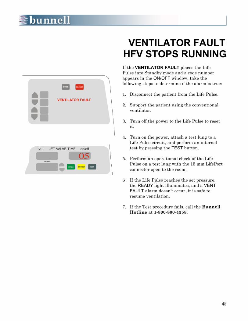
VENTILATOR FAULT:
HFV STOPS RUNNING
If the VENTILATOR FAULT places the Life Pulse into Standby mode and a code number appears in the ON/OFF window, take the following steps to determine if the alarm is true: 1. Disconnect the patient from the Life Pulse. 2. Support the patient using the conventional
ventilator. 3. Turn off the power to the Life Pulse to reset
it. 4. Turn on the power, attach a test lung to a
Life Pulse circuit, and perform an internal test by pressing the TEST button.
5. Perform an operational check of the Life
Pulse on a test lung with the 15 mm LifePort connector open to the room.
6 If the Life Pulse reaches the set pressure,
the READY light illuminates, and a VENT FAULT alarm doesn’t occur, it is safe to resume ventilation.
7. If the Test procedure fails, call the Bunnell
Hotline at 1-800-800-4358.
SILENCEENTER
VENTILATOR FAULT
TESTSTANDBY
JET VALVE TIMEon on/off
ENTER
seconds
05
49
TESTSTANDBY
JET VALVE TIMEon on/off
ENTER
seconds
10
SILENCEENTER
VENTILATOR FAULT
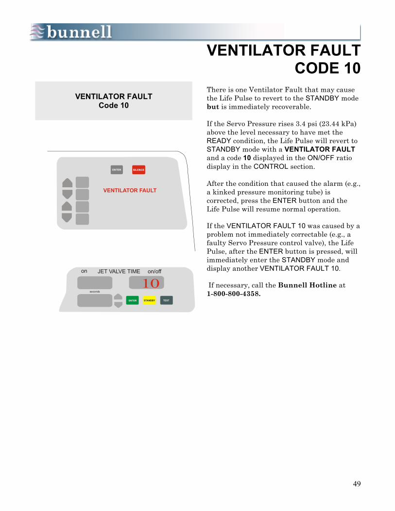
VENTILATOR FAULT CODE 10
There is one Ventilator Fault that may cause the Life Pulse to revert to the STANDBY mode but is immediately recoverable. If the Servo Pressure rises 3.4 psi (23.44 kPa) above the level necessary to have met the READY condition, the Life Pulse will revert to STANDBY mode with a VENTILATOR FAULT and a code 10 displayed in the ON/OFF ratio display in the CONTROL section. After the condition that caused the alarm (e.g., a kinked pressure monitoring tube) is corrected, press the ENTER button and the Life Pulse will resume normal operation. If the VENTILATOR FAULT 10 was caused by a problem not immediately correctable (e.g., a faulty Servo Pressure control valve), the Life Pulse, after the ENTER button is pressed, will immediately enter the STANDBY mode and display another VENTILATOR FAULT 10. If necessary, call the Bunnell Hotline at 1-800-800-4358.
VENTILATOR FAULT
Code 10
50
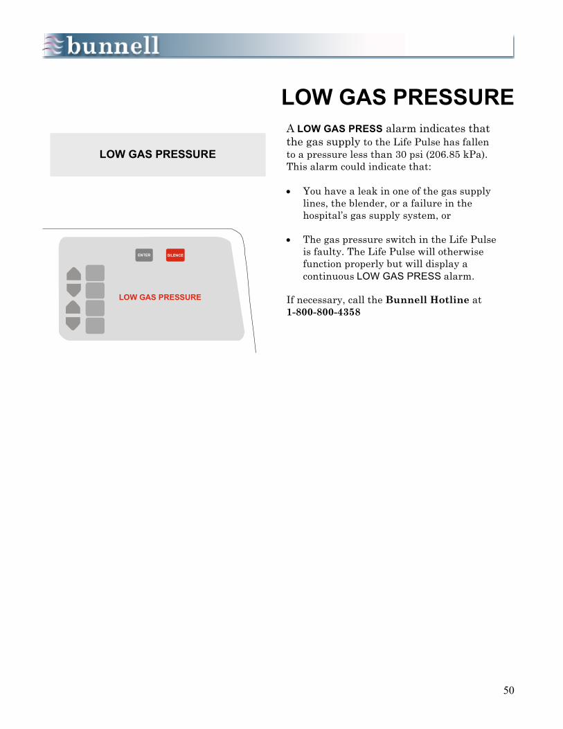
LOW GAS PRESSURE
A LOW GAS PRESS alarm indicates that the gas supply to the Life Pulse has fallen to a pressure less than 30 psi (206.85 kPa). This alarm could indicate that: • You have a leak in one of the gas supply
lines, the blender, or a failure in the hospital’s gas supply system, or
• The gas pressure switch in the Life Pulse
is faulty. The Life Pulse will otherwise function properly but will display a continuous LOW GAS PRESS alarm.
If necessary, call the Bunnell Hotline at 1-800-800-4358
SILENCEENTER
LOW GAS PRESSURE
LOW GAS PRESSURE

51
SILENCEENTER
CANNOT MEET PIP
CANNOT MEET PIP
A CANNOT MEET PIP alarm means one of two things: • the Life Pulse has been unable to meet
the Ready condition within 3 minutes of pressing the RESET or ENTER button; or,
• the Servo Pressure has risen to 20 psi
(137.90 kPa) and the Ready condition has not been met.
The first criteria would be met if conditions keep changing after the RESET or ENTER button is pressed. An unstable monitored PIP makes it difficult for the Life Pulse to meet the criteria necessary to enter the Ready condition. For example, a patient who is taking vigorous spontaneous breaths may initiate this alarm. The alarm may be alerting you that the patient needs comforting, attention, or possibly sedation. This condition can be simulated with a test lung by periodically creating leaks after pressing the ENTER button. The CANNOT MEET PIP alarm will occur after 3 minutes. The second criteria may be met with a relatively large patient on the Life Pulse, or if large leaks are present somewhere in the system. This condition can be simulated by using a test lung with a large air leak. In either case, the Life Pulse does not give up trying to meet the Ready condition. This alarm is simply informing you that the Life Pulse is taking longer than usual to meet the Ready condition. If necessary, call the Bunnell Hotline at 1-800-800-4358
CANNOT MEET PIP
CANNOT MEET PIP
Causes
1. Ready condition not met within 3 minutes
2. Servo Pressure reaches 20 psi
(137.90 kPa) before the Ready condition is met
52
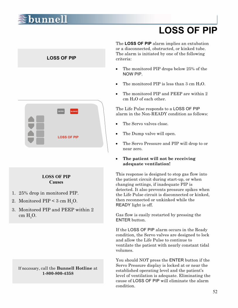
LOSS OF PIP
The LOSS OF PIP alarm implies an extubation or a disconnected, obstructed, or kinked tube. The alarm is initiated by one of the following criteria: • The monitored PIP drops below 25% of the
NOW PIP. • The monitored PIP is less than 3 cm H2O. • The monitored PIP and PEEP are within 2
cm H2O of each other. The Life Pulse responds to a LOSS OF PIP alarm in the Non-READY condition as follows: • The Servo valves close.
• The Dump valve will open. • The Servo Pressure and PIP will drop to or
near zero. • The patient will not be receiving
adequate ventilation! This response is designed to stop gas flow into the patient circuit during start-up, or when changing settings, if inadequate PIP is detected. It also prevents pressure spikes when the Life Pulse circuit is disconnected or kinked, then reconnected or unkinked while the READY light is off. Gas flow is easily restarted by pressing the ENTER button. If the LOSS OF PIP alarm occurs in the Ready condition, the Servo valves are designed to lock and allow the Life Pulse to continue to ventilate the patient with nearly constant tidal volumes. You should NOT press the ENTER button if the Servo Pressure display is locked at or near the established operating level and the patient’s level of ventilation is adequate. Eliminating the cause of LOSS OF PIP will eliminate the alarm condition.
SILENCEENTER
LOSS OF PIP
LOSS OF PIP
Causes
1. 25% drop in monitored PIP. 2. Monitored PIP < 3 cm H2O.
3. Monitored PIP and PEEP within 2 cm H2O.
LOSS OF PIP
If necessary, call the Bunnell Hotline at
1-800-800-4358

53
HIGH PIP
The HIGH PIP alarm indicates one of the following conditions: • the monitored pressure has exceeded the
set NOW PIP by at least 5 cm H2O for 1 second;
• the PIP has consistently exceeded the
NOW PIP by 10 cm H2O for all high-frequency breaths for the past 30 seconds; or,
• the monitored PIP for each breath during
a 0.75 second period exceeds the set point by 30 cm H2O, or,
• Instantaneous airway pressure > 65
cm H2O This alarm may be observed by pinching off the exhalation limb of the conventional circuit. Note that the Life Pulse Servo Pressure is “dumped” in this condition. Although it has no way of alleviating a condition caused by the conventional ventilator, the Life Pulse does ensure that it will not further aggravate the problem. All of the alarm conditions described in this section are accompanied by an audible alarm. While the cause of the alarm is being evaluated, the beeping may be silenced by pressing the Alarm SILENCE button. It may be necessary to review this section several times before becoming familiar with the conditions that trigger each alarm. Remember, all alarms are important and should be responded to by the operator. If necessary, call the Bunnell Hotline at 1-800-800-4358.
SILENCEENTER
HIGH PIP
HIGH PIP
HIGH PIP Causes
1. Pressure 5 cm > NOW PIP for
1 sec. 2. PIP 10 cm > NOW PIP for
each breath over a 30-second period
3. Monitored PIP > NOW PIP by 30 cm for each breath during a 0.75 sec. period.
4. Instantaneous airway pressure > 65 cm H2O

54
SILENCEENTER
JET VALVE FAULTVENTILATOR FAULT
LOW GAS PRESSURECANNOT MEET PIP
LOSS OF PIPHIGH PIP
Chapter 11 INTERPRETING VENTILATOR ALARMS
ALARM DISPLAY
This section discusses interpreting and correcting the ventilator alarms. It is beyond the scope of this manual to list all possible problems and their solutions. Many ventilator problems and corrective actions have already been covered. A more comprehensive review is offered in the Operator’s and Service manuals. There are, however, a few general principles that can simplify Life Pulse troubleshooting. Most of the necessary troubleshooting will be in response to alarms. Ventilator alarms alert the operator to changes in the patient or the Life Pulse. It is recommended that when a patient is on the Life Pulse the operator: • pays particular attention to ventilator
alarms; and, • sets the alarm volume loud enough to
present a sense of urgency when it sounds
There are at least five basic troubleshooting principles that, if followed, will help make working with patients on the Life Pulse easier.
Objectives 1. Understand the usefulness of ventilator alarms. 2. Know the “Five Principles” of ventilator troubleshooting.

55
LOOK AT THE PATIENT
First, as with any ventilator, observe the patient. Whenever an alarm occurs, LOOK AT THE PATIENT FIRST. • Is the patient’s chest rise adequate?
• How is the patient’s color?
• How is the patient’s external monitoring?
• Is there an obvious disconnected tube
near the patient?
• Has the Servo Pressure locked at or near its operating level? With the most common Life Pulse alarm, LOSS OF PIP, the Servo Pressure will lock and the patient will continue to receive a constant level of ventilation.
The cause of the alarm may then be determined without increasing conventional ventilator support or providing manual ventilation. However, some alarm conditions may require the conventional ventilator settings to be increased to provide ventilation while an alarm condition is corrected, or the patient may need to be hand bagged.
1. Look At The Patient

56
USE COMMON SENSE
Second, USE COMMON SENSE. There is no substitute for a skilled and alert therapist, nurse, or doctor who takes a logical approach to alarm interpretation. • The Life Pulse’s rhythmic sounds will
become familiar to you. Learn to recognize when the sounds have changed.
• The displayed and monitored values
should remain at consistent levels. Watch for changes in these levels and learn to understand what the changes mean.
For example, the Servo Pressure value reflects the gas flow and pressure required by the Life Pulse to produce the NOW settings on a patient. If the Servo Pressure changes, either suddenly or gradually, it may be that: • Lung compliance is changing.
• A pneumothorax has occurred.
• Tension is developing on a pneumothorax.
• A right mainstem intubation has occurred.
• The patient needs suctioning.
• There is a leak in the tubing.
Not all alarms require emergency corrective actions. Use common sense. If the Life Pulse alarms are saying one thing, and clinical observation says another, react accordingly. For example, if the humidifier displays a TEMP LOW alarm and the circuit and cartridge feels hot to the touch, place the humidifier into WAIT and replace the cartridge/circuit.
2. Use Common Sense

57
KNOW THE LIFE PULSE
Third, KNOW THE LIFE PULSE. Interpreting alarms is difficult, if not impossible, without a good working knowledge of the ventilator, how the feedback control mechanisms function, and what the various alarms mean. • What conditions can cause an alarm? • How does the Life Pulse respond to an
alarm? • What should the clinical response be? Review this manual and study the Operator’s Manual which, among other information, contains a comprehensive troubleshooting section. Interpreting alarm conditions is made easier when you know, for example, the HIGH PIP alarm means that the Life Pulse has sensed PIPs 10 cm H2O greater than the set PIP for every breath during the last 30 seconds, or a sustained PIP 5 cm H2O greater for 1 second.
3. Know The Life Pulse

58
COMMON THINGS HAPPEN COMMONLY
Fourth, common things are the most likely cause of the majority of alarms. COMMON THINGS HAPPEN COMMONLY. • Perhaps ninety-five percent of alarms occur
due to kinked, disconnected, or obstructed tubes. Knowing this information will help greatly in troubleshooting.
The solutions to these problems are equally as common: • Unkink the tubes, reconnect the tubes, or
clear the obstruction. Again, if the Servo Pressure has locked at or near its last operating level, the tubing problem can be corrected without manual ventilation or changing conventional ventilator settings.
4. Common Things Happen
Commonly

59
USE AVAILABLE RESOURCES
Fifth, USE AVAILABLE RESOURCES. Bunnell Incorporated offers an Operator’s Manual, newsletters, research articles, and a 24 hour Hotline:
800-800-4358 When using the Hotline, make sure to gather as much information about the alarm condition as possible. The more facts you have about the situation, the better the assistance a clinical specialist can provide on the Hotline. If an alarm condition cannot be corrected easily, perform a systems Test. The systems Test can help isolate the source of the alarm. If the Life Pulse passes the Test on the test lung, the cause of the alarm has to be in the ET tube or the patient. Also run an operational test on a test lung to verify the Life Pulse’s operation. Remember to call as soon as possible after determining the alarm condition cannot be corrected. Do not hesitate to call if there are any question or concern. It is much better to call and have a good experience than not call and have a bad experience.
5. Use Available Resources
Examples of
Available Resources
• In-service Manual • Operator’s Manual • Service Manual • Clinical Updates • Newsletters • Website - www.bunl.com • 24 Hour Hotline

60
Chapter 12
HUMIDIFIER ALARMS
The humidifier alarms are on the right side of the humidifier control panel. Humidifier alarms will appear as red LEDs accompanied by an audible alarm. The alarm can be silenced for 60 seconds by pressing the SILENCE button. The humidifier alarm system detects high or low water levels and high and low temperature for both the circuit and cartridge. The system also has an alarm for disrupted electrical connections between the humidifier and the cartridge.
WAIT HUMIDIFIER
TEMPERATURE
SET
CIRCUITCARTRIDGE
CIRCUITTEMP
SILENCE
CIRCUIT
LEVEL
TEMP
FAULT
LOW
HIGHALARMS
HIGH FREQUENCY VENTILATORLIFE PULSE
Objectives
1. Recognize and correct the conditions that will produce humidifier cartridge/circuit alarms.
2. Understand the purpose and methods of controlling gas temperature in the cartridge and circuit.
3. Understand how cartridge temperature is linked with humidification and when and how to change this temperature.
4. Understand the importance of the CIRCUIT TEMP, CARTRIDGE TEMP, WAIT button, and SILENCE button.
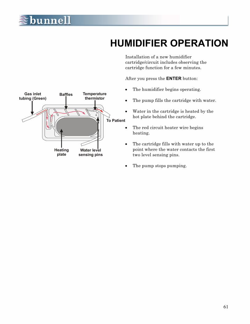
61
HUMIDIFIER OPERATION
Installation of a new humidifier cartridge/circuit includes observing the cartridge function for a few minutes. After you press the ENTER button:
• The humidifier begins operating. • The pump fills the cartridge with water. • Water in the cartridge is heated by the
hot plate behind the cartridge. • The red circuit heater wire begins
heating. • The cartridge fills with water up to the
point where the water contacts the first two level sensing pins.
• The pump stops pumping.
Gas inlettubing (Green)
Baffles Temperaturethermistor
Water levelsensing pins
Heatingplate
To Patient

62
SILENCESET
CARTRIDGECIRCUIT
CIRCUITTEMP
ALARMS
CIRCUIT
LEVEL
TEMP
FAULT
LOW
HIGH
CIRCUIT FAULT: LEVEL Alarm
The humidifier microprocessor knows that the pump should be able to fill the cartridge within eighty-six seconds. If the level sensing pins do not detect water within this period, the water pump will shut off and a CIRCUIT FAULT: LEVEL alarm will appear in the humidifier ALARMS window.
The alarm may be silenced for 60 seconds by pressing the humidifier alarm SILENCE button.
The CIRCUIT FAULT: LEVEL alarm indicates it is necessary to check the progress of the cartridge filling. If the water has reached the appropriate level as described above, the cartridge may need to be replaced.
If a CIRCUIT FAULT: LEVEL alarm sounds and the water has not reached it proper level, look for one of the following possible causes:
• The water supply and/or water transfer
tubing may not be connected properly. • The water transfer tubing may be
clamped shut. • The water supply may be empty.
If the CIRCUIT FAULT alarm sounds immediately after the ENTER button is pressed:
• The humidifier door may not be closed
properly. • The cartridge/circuit may be faulty.
If none of these conditions exists, call the Bunnell Hotline at 800-800-4358.

63
WATER LEVEL SENSING
While observing the delivery of water to the cartridge, ensure that it does not overfill. The pump stops pumping when the water level reaches the second water level sensing pin. The cartridge has a third level sensing pin to detect high water level and prevent overfill into the circuit. The water pump is stopped automatically if the water level reaches the third pin. If the all level sensing pins are defective, the water level isn’t sensed properly and a set fill time limit (86 seconds) is designed to turn off the pump in time to prevent overfill. Whenever installing a new cartridge/circuit, observe the cartridge fill until the pump stops.
As the cartridge fills, the water and gas inside are heated by the hot plate behind the cartridge. The temperature is regulated by the white cartridge thermistor wire located near where the circuit tubing attaches to the cartridge.
Proper water levelis at 2nd level sensing pin
Water levelsensing pins

64
CIRCUIT TEMPERATURE
The actual temperature of the gas is measured in the circuit just before the Patient Box and is displayed in the humidifier monitor section as CIRCUIT TEMP with a green light. As this temperature adjusts, it will approach 40o C, may overshoot slightly and then settle in right at or near 40o C. There is approximately a 3o C drop in gas temperature from where it is last measured to where it enters the patient’s trachea. If the set circuit temperature is 40o C, the actual temperature of the gas as it enters the patient will be 37o C (body temperature). The lungs are very effective heat exchangers. Unless there is a reason for wanting to raise or lower the patient’s core temperature, do not adjust the Circuit temperature to any value other than 40o C.
WAIT HUMIDIFIER
TEMPERATURE
SET
CIRCUITCARTRIDGE
CIRCUITTEMP
The actual Circuit Temperature will be 40 C andwill be indicated by a green LED
o

65
TEMPERATURE CONTROLS
We recommend that the set CIRCUIT temperature remain at its default setting of 40o C. Adjust the Circuit Temperature only if the patient’s temperature is not within an expected range, and if there is a reason to believe the temperature of the delivered gas may be contributing to the problem. Adjusting the Circuit temperature may affect humidification in the circuit tubing. Be ready to change the Cartridge Temperature to provide appropriate levels of humidification. The temperature in the cartridge and the circuit tubing are set and controlled independently. Pressing the SET button repeatedly causes the LED to alternate between CIRCUIT, CARTRIDGE, and CIRCUIT TEMP readings. • A red or yellow light indicates a set
temperature. • A green light indicates an actual
temperature.
WAIT HUMIDIFIER
TEMPERATURE
SET
CIRCUITCARTRIDGE
CIRCUITTEMP
Pressing the SET button repeated will scroll throughthe Circuit, Cartridge, and Circuit Temp LEDs.
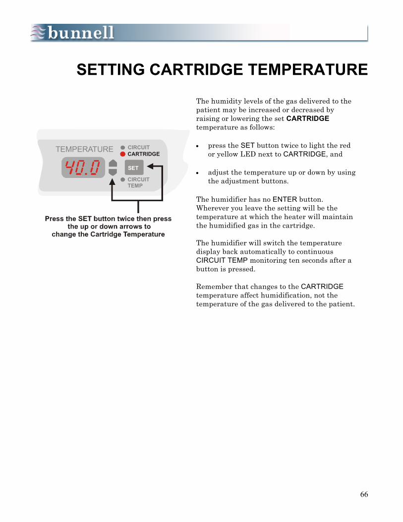
66
SETTING CARTRIDGE TEMPERATURE
The humidity levels of the gas delivered to the patient may be increased or decreased by raising or lowering the set CARTRIDGE temperature as follows: • press the SET button twice to light the red
or yellow LED next to CARTRIDGE, and • adjust the temperature up or down by using
the adjustment buttons. The humidifier has no ENTER button. Wherever you leave the setting will be the temperature at which the heater will maintain the humidified gas in the cartridge. The humidifier will switch the temperature display back automatically to continuous CIRCUIT TEMP monitoring ten seconds after a button is pressed. Remember that changes to the CARTRIDGE temperature affect humidification, not the temperature of the gas delivered to the patient.
TEMPERATURE
SET
CIRCUITCARTRIDGE
CIRCUITTEMP

67
CONDENSATION PROBLEMS
A LOSS OF PIP alarm with the READY light on will lock the Servo Pressure.
The patient will continue to be ventilated appropriately.
If the preset Cartridge Temperature is too high for a patient: • Excess condensation will develop in the
clear portion of the Life Pulse circuit between the cartridge and the Patient Box.
• The MONITOR section of the Life Pulse
will display fluctuating pressures. • A LOSS OF PIP alarm may occur. • As long as the Life Pulse is in the READY
mode, the Servo Pressure will lock at or near its operating level, and the Life Pulse will continue to ventilate the patient appropriately during a LOSS OF PIP alarm
If the Cartridge temperature is set too low: • The green portion of the Life Pulse
circuit between the Patient Box and the LifePort adapter will be dry.
CARTRIDGE TEMP too high
CARTRIDGE TEMP too low
SILENCEENTER READY
SERVOPRESS
PSI
LOSS OF PIP
UPPERLIMIT
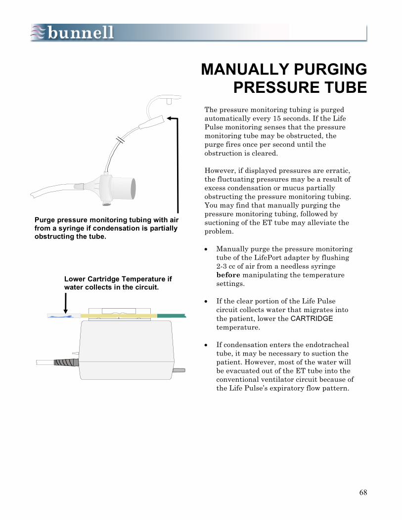
68
MANUALLY PURGING
PRESSURE TUBE
The pressure monitoring tubing is purged automatically every 15 seconds. If the Life Pulse monitoring senses that the pressure monitoring tube may be obstructed, the purge fires once per second until the obstruction is cleared. However, if displayed pressures are erratic, the fluctuating pressures may be a result of excess condensation or mucus partially obstructing the pressure monitoring tubing. You may find that manually purging the pressure monitoring tubing, followed by suctioning of the ET tube may alleviate the problem.
• Manually purge the pressure monitoring
tube of the LifePort adapter by flushing 2-3 cc of air from a needless syringe before manipulating the temperature settings.
• If the clear portion of the Life Pulse
circuit collects water that migrates into the patient, lower the CARTRIDGE temperature.
• If condensation enters the endotracheal
tube, it may be necessary to suction the patient. However, most of the water will be evacuated out of the ET tube into the conventional ventilator circuit because of the Life Pulse’s expiratory flow pattern.
Purge pressure monitoring tubing with air from a syringe if condensation is partially obstructing the tube.
Lower Cartridge Temperature if water collects in the circuit.
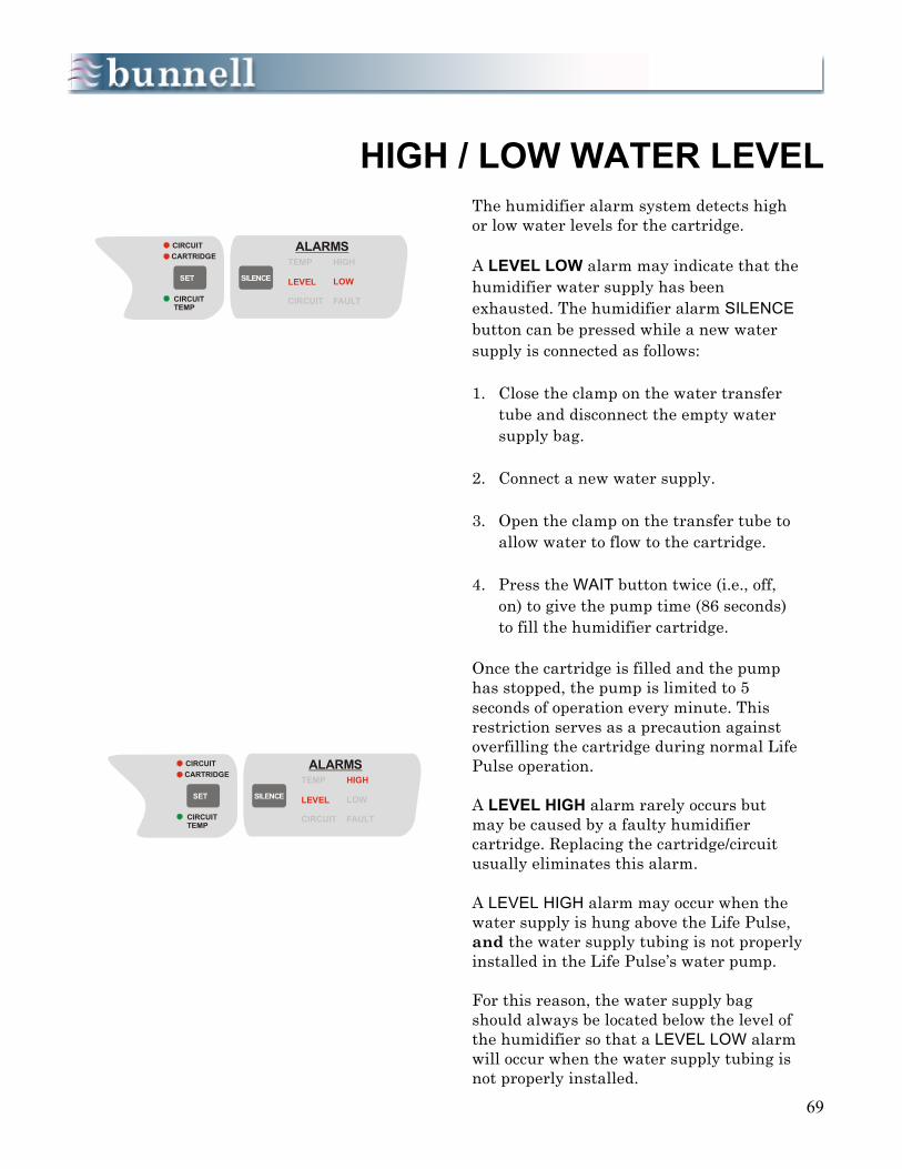
69
HIGH / LOW WATER LEVEL
The humidifier alarm system detects high or low water levels for the cartridge. A LEVEL LOW alarm may indicate that the humidifier water supply has been exhausted. The humidifier alarm SILENCE button can be pressed while a new water supply is connected as follows:
1. Close the clamp on the water transfer
tube and disconnect the empty water supply bag.
2. Connect a new water supply. 3. Open the clamp on the transfer tube to
allow water to flow to the cartridge. 4. Press the WAIT button twice (i.e., off,
on) to give the pump time (86 seconds) to fill the humidifier cartridge.
Once the cartridge is filled and the pump has stopped, the pump is limited to 5 seconds of operation every minute. This restriction serves as a precaution against overfilling the cartridge during normal Life Pulse operation. A LEVEL HIGH alarm rarely occurs but may be caused by a faulty humidifier cartridge. Replacing the cartridge/circuit usually eliminates this alarm. A LEVEL HIGH alarm may occur when the water supply is hung above the Life Pulse, and the water supply tubing is not properly installed in the Life Pulse’s water pump. For this reason, the water supply bag should always be located below the level of the humidifier so that a LEVEL LOW alarm will occur when the water supply tubing is not properly installed.
SILENCESET
CARTRIDGECIRCUIT
CIRCUITTEMP
ALARMS
CIRCUIT
LEVEL
TEMP
FAULT
LOW
HIGH
SILENCESET
CARTRIDGECIRCUIT
CIRCUITTEMP
ALARMS
CIRCUIT
LEVEL
TEMP
FAULT
LOW
HIGH

70
HIGH / LOW TEMPERATURE
The humidifier alarm system detects high and low temperature for both the circuit and cartridge. A high or low temperature is indicated by an audible alarm and a TEMP HIGH or TEMP LOW message in the alarm display. The TEMP HIGH alarm is activated if: • the monitored temperature strays 3o
above the set temperature for more than 1 minute in the circuit; or
• the monitored temperature strays 3o
above the set temperature for more than 10 minutes in the cartridge.
• The TEMP LOW alarm is activated if:
• the monitored temperature strays 3o below the set temperature for more than 3 minutes in the circuit; or
• the monitored temperature strays 3o
below the set temperature for more than 30 minutes in the cartridge.
Such alarms may be caused by a faulty circuit relaying false information to the microprocessor. For example, if the circuit is quite warm to the touch when the humidifier is indicating that it is too cold, it could result in overheating. The humidifier circuit might need to be replaced in such conditions. Call the Bunnell Hotline at 800-800-4358 before changing the circuit
SILENCESET
CARTRIDGECIRCUIT
CIRCUITTEMP
ALARMS
CIRCUIT
LEVEL
TEMP
FAULT
LOW
HIGH
SILENCESET
CARTRIDGECIRCUIT
CIRCUITTEMP
ALARMS
CIRCUIT
LEVEL
TEMP
FAULT
LOW
HIGH
71
Appendix A POST-TEST QUESTIONS
Section 1
OVERVIEW 1. The five subsystems of the Life Pulse are ____________, ____________,
___________, ____________, and ____________. 2. Pressures measured in the patient are displayed in the ____________ section. 3. To make ventilator changes in high-frequency Rate, PIP, and On-Time, use the
buttons and displays in the ____________ section. 4. The Patient Box is where blended gas is broken up into small “pulses” which
then provide the patient with breaths necessary for ventilation. T q F q 5. The Life Pulse is routinely used without attaching a conventional ventilator. T q F q 6. The Life Pulse is designed to improve the patient’s blood gases while using less
pressure. T q F q 7. Each ventilator performs distinct functions when using a conventional ventilator
in tandem with the Life Pulse. Check which ventilator primarily performs the following functions. Check both ventilators if they provide an equally important function.
Life Pulse Conventional ___ a. Provides gas for patient’s spontaneous breathing. ___ ___ b. Monitors Mean Airway Pressure (MAP). ___ ___ c. Controls Positive End Expiratory Pressure (PEEP). ___ ___ d. Controls high-frequency Rate and PIP. ___ ___ e. Provides supplementary IMV. ___ ___ f. Humidifies blended gas delivered to the patient. ___ ___ g. Blends oxygen and compressed air. ___ 8. A major advantage of the LifePort adapter is that reintubation is not required in
order to provide high-frequency ventilation. T q F q

72
Appendix A POST-TEST QUESTIONS
Section 2 SET UP
REAR PANEL 1. The Life Pulse’s power cord may be plugged into a standard electrical outlet or an
uninterruptible power supply. T q F q 2. Oxygen and compressed air must be blended before entering the Life Pulse. T q F q 3. At least 30 psi (206.85 kPa) of gas pressure must be supplied for the Life Pulse to
operate. T q F q 4. Analyzing FiO2 is best performed by measuring directly from the air/oxygen blender. T q F q 5. The Life Pulse alarm volume level is not adjustable. T q F q FRONT PANEL 6. The disposable humidifier cartridge/circuit consists of which of the following: a. Electrical sensors b. Heating elements c. Purge tubing d. Humidification cartridge e. All of the above 7. The pinch valve is located in the Patient Box. T q F q 8. Either sterile water or normal saline may be used in the humidifier cartridge. T q F q 9. Once the humidifier cartridge/circuit has been installed, three tubes will need to be
connected to the front panel of the Life Pulse. Attach the small clear tube to the barbed connector labeled PURGE; attach the green gas inlet tube to the barbed connector labeled GAS OUT, and latch the clear water inlet tube into the pump housing.
T q F q 10. The pinch tube portion of the humidifier cartridge/circuit is the only tube that should be
between the jaws of the pinch valve. T q F q

73
Appendix A POST-TEST QUESTIONS Section 3
VENTILATOR CONTROLS AND TEST PROCEDURE
1. An immediate audible alarm after the Life Pulse is turned on means the ventilator is defective.
T q F q 2. The STANDBY button stops jet ventilation from being delivered to the patient. T q F q 3. The STANDBY button:
a. should be pressed each time a parameter is changed in the CONTROLS section. b. puts the Life Pulse through a systems test. c. creates a brief audible alarm every 30 seconds. d. none of the above.
4. A systems TEST may be performed only with the Life Pulse in the Standby mode and should never be performed while the Life Pulse is attached to the patient.
T q F q 5. It is important to observe the front panel of the Life Pulse during the TEST procedure to
assure all LEDs and displays are functional. T q F q 6. Match each item in the first column with the single most accurate statement in the
second column.
1. ENTER button ____ a. Never pressed while the Life Pulse is attached to the patient
2. NOW settings ____ b. Stops the audible alarm for 60 seconds 3. TEST button ____ c. “Awakens” the Life Pulse into the Standby mode
with an audible alarm 4. ON button ____ d. Transfers NEW settings to NOW settings. 5. NEW settings ____ e. Disconnected purge tubing 6. SILENCE button ____ f. The current or active PIP, RATE, and ON-Time 7. STANDBY button ____ g. Problem with connection at GAS OUT hose barb
or with one of the Servo Pressure control valves 8. VENTILATOR ____ h. Similar to Inspiratory Time
FAULT 02 9. VENTILATOR ____ i. Proposed PIP, RATE, and ON Time
FAULT 03 10. JET VALVE ____ j. Stops high-frequency ventilation delivery ON-TIME

74
Appendix A POST-TEST QUESTIONS
Section 4 PRESSURE MONITORING
1. What pressure is displayed in the MONITOR section when the Life Pulse is in the
Standby mode and not attached to a patient?
a. Servo Pressure b. MAP c. proposed PIP d. Zeros will be displayed e. a., b., and c.
2. Once the pressure monitoring tube of the LifePort adapter has been connected to the
Patient Box, the Life Pulse, in its Standby mode, will begin to monitor the pressures being delivered by the conventional ventilator. These pressures are measured every 2 milliseconds, averaged over ________ seconds, and updated on the display every ________ seconds.
3. Match one MONITOR feature in the first column with its definition in the second
column:
1. MAP a. The internal driving or working pressure required to ventilate the patient at the NOW settings
2. D P b. Average of peak pressures measured in the LifePort. 3. PEEP c. PIP minus PEEP 4. PIP d. Average of pressures measured over the total area of
the pressure waveform 5. SERVO e. Average of minimum airway pressure
4. Bigger patients, or patients with more compliant lungs, require ________
(MORE/LESS) Servo Pressure.
5. The Purge system maintains the patency of which tube? a. Jet port
b. Main port of the endotracheal tube c. Pressure monitoring tube

75
Appendix A POST-TEST QUESTIONS
Section 5
HUMIDIFIER
1. Lowering the cartridge temperature will reduce the amount of humidity in the gas but will not affect the temperature of the gas that is delivered to the patient. T q F q
2. There are two separate temperature controls for the humidifier cartridge/circuit.
T q F q
3. Improper regulation of the humidity and temperature of the gas delivered to the patient may: (choose all that apply) a. contribute to dehydration. b. contribute to fluid overload. c. raise the patient’s body temperature. d. lower the patient’s body temperature. e. contribute to mucus plugging.
4. It is important to check for proper humidification (misty or condensation) in the green
portion of the Life Pulse circuit between the Patient Box and the LifePort. T q F q
5. The humidity of the gas delivered to the patient is:
a. primarily controlled by the Circuit temperature. b. determined by the Cartridge temperature. c. controlled in response to measurements taken by the Cartridge thermistor.
6. The temperature regulation in the Patient Circuit tubing:
a. primarily controls the temperature of the gas going to the patient. b. is used to control condensation in the Circuit tubing. c. is controlled in response to measurements taken by the thermistor in the circuit
just before the Patient Box. d. a. and c. only.
7. The Circuit temperature stays at 40o C and the Cartridge temperature is adjusted as
necessary to control condensation and rainout. T q F q
8. If a small red light on the Humidifier’s WAIT button is flashing, the Humidifier has
been placed in its WAIT mode manually, and the button must be pressed by the operator to return the humidifier to normal operation. T q F q

76
Appendix A
POST-TEST QUESTIONS
Section 6 START UP
1. To begin high-frequency Jet ventilation, attach the Life Pulse to the patient, monitor
conventional ventilator pressures with the Life Pulse in Standby mode, and determine the initial Life Pulse settings. T q F q
2. In the Standby mode, the pressures displayed in the MONITOR section are 80-second
running averages updated every 10 seconds. During operation, the displayed pressures are 10-second running averages updated every 2 seconds. T q F q
3. If air leak is the primary concern, select a PIP approximately 90-100% of the
monitored conventional ventilator PIP. If the primary concern is RDS, select a PIP 100-110% of the monitored conventional ventilator PIP. T q F q
4. Number the following Start-up steps according to the order in which they occur.
____ a. Adjust PEEP, if necessary ____ b. Select starting PIP ____ c. Lower conventional ventilator Rate ____ d. Lower conventional ventilator PIP if interrupting jet pulses ____ e. Press ENTER button ____ f. Press RESET button to establish new alarm limits, if necessary
5. A 10% drop in PIP with the Life Pulse typically results in a 20 to 25% drop in MAP, a
reduction that may be too great in the RDS patient. T q F q
6. After making a change in the conventional ventilator settings, it may be necessary to:
a. make the same changes on the Life Pulse. b. press the RESET button to allow the Life Pulse to recalculate alarm limits around
the Servo and Mean Airway Pressures. c. lower the RATE on the Life Pulse. d. Both a. and c. e. None of the above.
77
Appendix A POST-TEST QUESTIONS
Section 7
PATIENT MANAGEMENT
1. The thought processes and rationale for managing patients on the Life Pulse as compared with a conventional ventilator are very similar. T q F q
2. Which of the following statements regarding patient management is (are) true? (Circle
all that apply)
a. Most setting changes to manage PCO2 will be performed on the Life Pulse. b. Most setting changes to manage PO2 will be performed on the conventional
ventilator. c. The Life Pulse is used in tandem with the conventional ventilator to provide
better blood gases while using less airway pressure. d. All of the above. e. a. and b. only.
3. The best approach for dealing with a high PCO2 is to increase delta P (DP).
T q F q
4. Because CO2 elimination is proportional to Tidal Volume squared ( VT2 ) during high-
frequency ventilation, small changes in which of the following parameters may produce significant changes in PCO2? (Circle all that apply)
a. PIP b. PEEP c. Delta P d. All of the above
5. PCO2 would most likely ______________ (INCREASE/DECREASE) if PEEP is
increased to improve PO2.
6. Increasing high-frequency PIP is a more effective means of eliminating PCO2 than increasing high-frequency Rate. T q F q
7. The best approach for controlling PO2 is to adjust Mean Airway Pressure (MAP).
T q F q
78
Appendix A POST-TEST QUESTIONS
Section 7
PATIENT MANAGEMENT Cont.
8. Which of the following strategies may be the most effective for increasing MAP and
oxygenation?
a. Increasing PEEP b. Increasing conventional IMV c. Increasing conventional inspiratory time d. Increasing high-frequency On-time e. Increasing high-frequency PIP
In the following two scenarios, match the most appropriate ventilator strategy with the patient’s specific pathophysiology.
9. A near term infant with a. Increase FiO2
a spontaneous pneumothorax and pneumomediastinum; b. Set initial conventional IMV rates 0 to 3 bpm minimal oxygenation concerns but excessively high PCO2. c. Set initial conventional IMV rates 3 to 5 bpm ____ ____ ____ d. Increase high-frequency PIP by 1 to 2 cm H2O e. Increase PEEP
10. A premature infant with RDS requiring high pressures; f. Increase conventional IMV rate to 10 bpm worsening oxygenation. g. Decrease PEEP ____ ____ ____ ____
11. Changing the high-frequency On-Time has not been proven an effective means of improving oxygenation. T q F q

79
Appendix A POST-TEST QUESTIONS
Section 8
SUCTIONING THE PATIENT
1. There are three methods of suctioning a patient while on the Life Pulse. T q F q
2. Secretions and suctioning frequency may ______________ (INCREASE/DECREASE)
during the first 4 to 6 hours of high-frequency ventilation.
3. The technique(s) for suctioning during high-frequency ventilation is (are):
a. to place the Life Pulse in Standby mode and suction normally. b. to leave the Life Pulse running, instill normal saline down the Jet port of the LifePort
adapter, and apply suction in both directions, while introducing and withdrawing the suction catheter.
c. to use a closed-suction system. d. All of the above
4. If the Life Pulse is placed in Standby mode for suctioning, the patient will not require
manual resuscitation or increased support from the conventional ventilator. T q F q
5. Once the suctioning procedure is completed, push the ENTER buttton and walk away..
T q F q

80
Appendix A POST-TEST QUESTIONS
Section 9
WEANING
1. Which of the following statements regarding weaning is false?
a. If the Life Pulse is not needed for another patient, a baby may be weaned from high-frequency ventilation down to CPAP.
b. Weaning too quickly is a vital concern and should be avoided. c. If a separate blender is being used to supply mixed gas to the Life Pulse, both
blenders should be adjusted to wean FiO2 . d. Conventional pressures and/or breaths may need to be increased gradually when
the Life Pulse pressures have been decreased into the teens. e. The Life Pulse Rate should always be lowered to its minimum setting of 240 bpm
before returning the patient to conventional ventilation.
2. The Servo Pressure may indicate when a patient’s compliance is improving. T q F q
3. Generally, as PCO2 decreases, high-frequency PIP is lowered in increments of 1 to 2
bpm; as PO2 improves, the FiO2 or the parameters that produce MAP are lowered. T q F q
4. When a patient begins to respond negatively to further decreases in pressure, it may
indicate that the patient has reached a “pressure threshold” and further decreases are ill-advised until the patient has “acclimated” to the changes. T q F q
5. FiO2 should be reduced to 40% or less before weaning PEEP.
T q F q
6. Interruptions in the jet pulses should never be allowed during any stage of the weaning procedure. T q F q
7. The conventional ventilator rate and PIP usually need to be increased as Life Pulse
PIP is weaned into the mid-teens. T q F q
8. When the patient is stable and most of the chest rise is being provided by the
conventional ventilator breaths, a trial of conventional ventilation alone may be attempted by pressing the STANDBY button on the Life Pulse. T q F q

81
Appendix A POST-TEST QUESTIONS
Section 10
VENTILATOR ALARMS 1. The four components of the ALARMS section are: upper and lower alarm limits, alarm
messages, the SILENCE button, and the RESET button. T q F q 2. The displayed values which have manually adjustable upper and lower alarm limits
are: (check all that apply) a. PIP b. DP c. PEEP d. Servo Pressure e. MAP 3. The READY condition is met when the monitored PIP has come to within ______ cm
H2O of the set NOW PIP and has stabilized there for ______ seconds. 4. It is important to never walk away from the Life Pulse until the READY light is
illuminated. T q F q 5. The Servo and Mean Airway Pressure alarm limits are set automatically and are not
manually adjustable. T q F q 6. A JET VALVE FAULT alarm may indicate that the electronics controlling the pinch
valve have failed. T q F q 7. The patient should be left attached to the Life Pulse when pressing the TEST button
to perform a systems test in the Standby mode. T q F q 8. If the Life Pulse continues to run with the VENTILATOR FAULT message, chances
are one of the ends of the purge tube has become disconnected. T q F q 9. If a VENTILATOR FAULT 10 alarm occurs, the Life Pulse will resume operating
when the ENTER button is pressed. T q F q
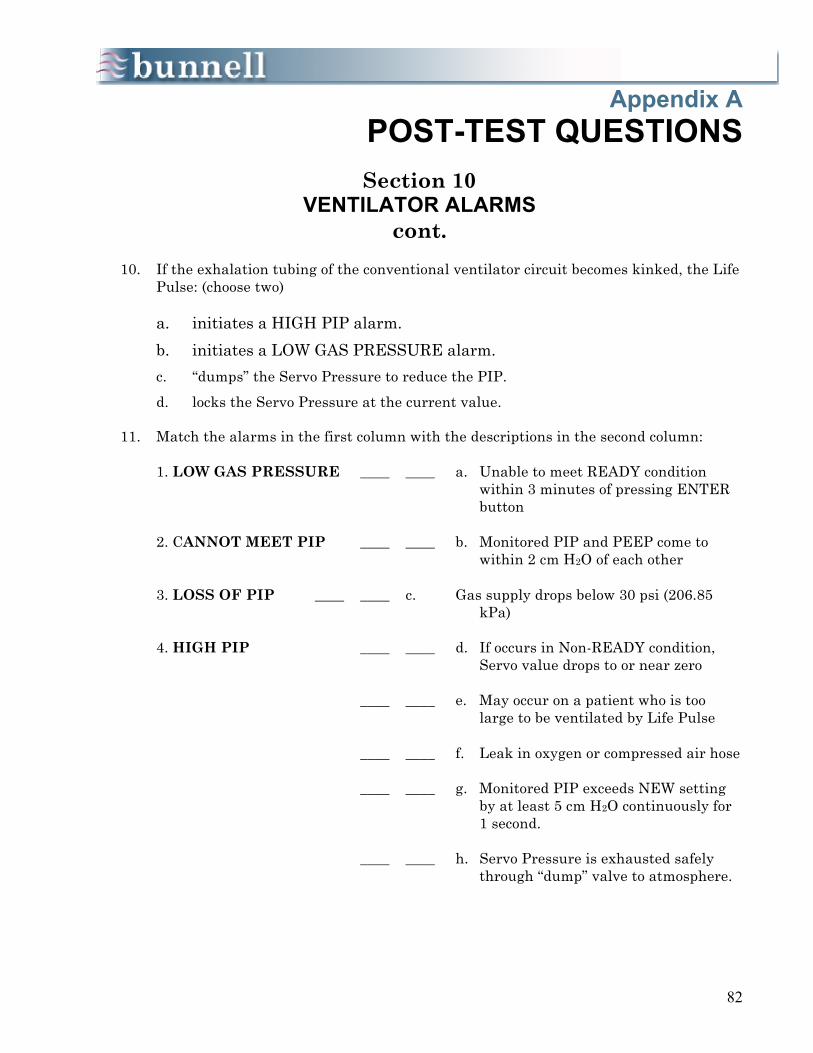
82
Appendix A POST-TEST QUESTIONS
Section 10
VENTILATOR ALARMS cont.
10. If the exhalation tubing of the conventional ventilator circuit becomes kinked, the Life
Pulse: (choose two) a. initiates a HIGH PIP alarm. b. initiates a LOW GAS PRESSURE alarm. c. “dumps” the Servo Pressure to reduce the PIP. d. locks the Servo Pressure at the current value. 11. Match the alarms in the first column with the descriptions in the second column: 1. LOW GAS PRESSURE ____ ____ a. Unable to meet READY condition
within 3 minutes of pressing ENTER button
2. CANNOT MEET PIP ____ ____ b. Monitored PIP and PEEP come to
within 2 cm H2O of each other 3. LOSS OF PIP ____ ____ c. Gas supply drops below 30 psi (206.85
kPa) 4. HIGH PIP ____ ____ d. If occurs in Non-READY condition,
Servo value drops to or near zero ____ ____ e. May occur on a patient who is too
large to be ventilated by Life Pulse ____ ____ f. Leak in oxygen or compressed air hose ____ ____ g. Monitored PIP exceeds NEW setting
by at least 5 cm H2O continuously for 1 second.
____ ____ h. Servo Pressure is exhausted safely
through “dump” valve to atmosphere.

83
Appendix A POST-TEST QUESTIONS
Section 11
INTERPRETING VENTILATOR ALARMS
1. Many alarms can be prevented by learning how the Life Pulse is designed, understanding its operation, and performing careful and thorough ventilator checks. However, when an alarm occurs, the first thing to do is look at the _____________.
2. Some alarm conditions may require manual ventilation or increased conventional
ventilator support while adjustments are made to the Life Pulse. T q F q 3. “There is no substitute for a skilled and alert ______________, ______________, or
______________.” 4. Careful observation is one aspect of using common sense when troubleshooting. An
example of this skill is: a. watching for appropriate chest rise. b. looking for proper condensation in the circuit. c. listening to the sounds of the Life Pulse for correct operation. d. knowing baseline operating levels and observing trends. e. All of the above. 5. If Servo Pressure exhibits an upward trend, the patient’s compliance may be
improving or there may be an air leak, either in the patient or the cartridge/circuit. T q F q 6. Knowing the ventilator is an important principle for understanding how to
troubleshoot the Life Pulse. T q F q 7. A majority of alarms are caused by kinked, disconnected, or obstructed tubes. T q F q 8. One of the most important resources available to clinicians using the Life Pulse is the
trained customer service representative answering the Bunnell 24-hour Hotline. T q F q 9. The Operator’s Manual is a valuable resource for understanding the Life Pulse since it
details information not covered in the In-Service Manual. T q F q

84
Appendix A POST-TEST QUESTIONS
Section 12
INTERPRETING HUMIDIFIER ALARMS
1. A humidifier CIRCUIT FAULT alarm may be caused by: a. broken cartridge or circuit wires. b. impaired contact between electrical connections (e.g., cartridge door open). c. water in the cartridge not reaching the appropriate level within the allotted fill time. d. All of the above. 2. The Circuit temperature is best left at 40o C because the gas temperature drops 3o
from where it is last heated to where it enters the patient. T q F q 3. Match the following: Circuit temperature ____ a. Primarily controls humidity of delivered gas. Cartridge temperature ____ b. Primarily controls temperature of delivered gas. 4. Which of the following alarms is not found in the Humidifier Section? a. LEVEL LOW b. TEMP HIGH c. LEVEL HIGH d. TEMP LOW e. VENTILATOR FAULT 5. Excessive rainout in the clear portion of the circuit may enter the ET tube and impede
pressure monitoring causing a LOSS OF PIP alarm. T q F q 6. If the cartridge door is closed and secured, if all tubing and electrical connections have
been made, if water is in the water supply bag, and if the water transfer tubing is patent, and the humidifier appears to be working normally, a TEMP HIGH or LOW or a LEVEL HIGH or LOW alarm usually means the operator should:
a. press the WAIT button and continue delivering high-frequency Jet ventilation. b. adjust the Cartridge and Circuit temperature settings. c. probably replace the Humidifier Cartridge/Circuit. d. call the Bunnell Hotline for additional troubleshooting ideas. e. c and d only

85
Appendix B POST-TEST ANSWERS
Section 1
OVERVIEW
1. CONTROLS, MONITOR , ALARMS, HUMIDIFIER, AND the Patient Box. 2. MONITOR. 3. CONTROL. 4. True. 5. False. The Life Pulse is always used in tandem with a conventional ventilator. 6. True. The conventional ventilator and the Life Pulse work synergistically to
improve the patient’s blood gases using less pressure, in most cases. 7. a. Conventional only. b. Life Pulse and some Conventional. c. Conventional only d. Life Pulse only. e. Conventional only. f. Both. g. Conventional. (Unless the conventional ventilator has a low flow external
output, a separate oxygen blender provides mixed gas to the Life Pulse) 8. True. The LifePort adapter replaces the standard ET tube adapter and obviates
the need to reintubate the patient.

86
Appendix B POST-TEST ANSWERS
Section 2
SET UP 1. True. However, the uninterruptible power source is more desirable. 2. True. The Life Pulse does not have an internal blender. 3. True. Pressures under 30 psi (206.85 kPa) will cause a LOW GAS PRESS alarm. 4. True. 5. False. The alarm volume knob is located on the rear panel of the Life Pulse. 6. e. All of the above. 7. True. 8. False. Only sterile water should be used to properly humidify the gas and assure
normal function of the cartridge. 9. True. Once the cartridge is placed in the cartridge door and the door is closed, the
tubes must be attached to the Life Pulse. 10. True. The pinch tube is the only circuit section flexible enough to function in the
pinch valve.
87
Appendix B POST-TEST ANSWERS
Section 3
VENTILATOR CONTROLS AND TEST PROCEDURE
1. False. When the Life Pulse is powered up it always “awakens” in the Standby mode with the alarm sounding.
2. True. Pressing STANDBY is the accepted method of stopping high-frequency ventilation while still allowing the Life Pulse monitoring to be active. 3. c. In the Standby mode, the Life Pulse beeps six times every thirty
seconds to inform you that it is not ventilating. 4. True. The TEST button should only be pushed with the ventilator attached
to a test lung. Pressing the TEST button will not initiate the systems test when the Life Pulse is running.
5. True. 6. 1-d; 2-f; 3-a; 4-c; 5-i; 6-b; 7-j; 8-e; 9-g; 10-h.

88
Appendix B POST-TEST ANSWERS
Section 4 PRESSURE MONITORING
1. d. “zero pressure.” All displays will be zero. 2. “80”, “10”. However, during operation all pressures are averaged over a 10 second
period and the display is updated every 2 seconds. This approach helps to produces more stable readings.
3. 1-d; 2-c; 3-e; 4-b; and 5-a. 4. MORE. 5. C. Pressure monitoring tube.

89
Appendix B POST-TEST ANSWERS
Section 5
HUMIDIFIER
1. True. The cartridge temperature may be reduced to minimize condensation; however, the heated wire circuit will assure that the temperature of the gas remains stable.
2. True. Temperature in the cartridge and in the circuit tubing are controlled
separately. 3. a, b, c, d, e. All of these are complications of improperly regulated humidification,
with high-frequency ventilation and conventional ventilation. 4. True. 5. b and c only. 6. d. Condensation is controlled by adjusting the Cartridge temperature.
The Circuit temperature should normally remain at 40° C 7. True. 8. True. If the humidifier is placed in the WAIT mode manually (indicated by a
flashing WAIT button), it must be restarted manually.

90
Appendix B POST-TEST ANSWERS
Section 6 START UP
1. True. 2. True. 3. True. However, these starting criteria may vary depending on the patient’s
pathophysiology. 4. a-5, b-1, c-4, d-3, e-2, f-6. 5. True. 6. b.

91
Appendix B POST-TEST ANSWERS
Section 7
PATIENT MANAGEMENT
1. True. 2. d. 3. True. Delta P can be increased by raising the Life Pulse PIP or by
decreasing the PEEP. 4. d. Delta P is PIP minus PEEP. 5. EITHER. Raising PEEP might decreases Tidal Volume and may result in CO2
retention if, despite raising PEEP, alveoli remain unstable at the end of expiration. However, if by raising PEEP the alveoli are stabilized at the end of expiration, CO2 may decrease.
6. True. 7. True. 8. a. MAP and PEEP have a 1-to-1 ratio, meaning that raising the PEEP by
1cm H2O raises the MAP by 1 cm H2O. 9. b, d, g. Concern for pulmonary airleaks means limiting tidal volume form
IMV breaths, but increasing minute ventilation using HFJV. Increasing HFJV PIP is more effective than increasing HFJV Rate for lowering PCO2. Decreasing PEEP will increase delta pressure, thus tidal volume, and may help lower PCO2.
10. a, c, e, f. Concern for oxygenation would lead to actions that recruit and
maintain lung volume. Except for increasing FiO2, all options involve increasing Mean Airway Pressure. Using more IMV breaths improves lung volume recruitment, and raising PEEP maintains recruitment. Once oxygenation improves (alveoli are open and stable), wean the IMV rate as tolerated.
11. True. Clinical trials have shown that changing high-frequency On-Time has
little clinical value, except possibly at slow ventilator rates while weaning and trying to maintain a desired I:E ratio.
92
Appendix B POST-TEST ANSWERS
Section 8
SUCTIONING THE PATIENT
1. False. It is recommened to place the Life Pulse in Standby before suctioning. 2. INCREASE. 3. a, c. It is not recommmend to suction a patient with the Life Pulse
running. 4. False. 5. False. After pressing the ENTER button, always make sure the monitored
pressures are stable and the READY light is on before leaving the patient’s bedside.

93
Appendix B POST-TEST ANSWERS
Section 9 WEANING
1. e. 2. True. 3. True. 4. True. 5. True. 6. False. 7. True. 8. True.

94
Appendix B POST-TEST ANSWERS
Section 10
VENTILATOR ALARMS
1. True. 2. d. and e. 3. ± 1.5, 20. 4. True. 5. False. The Servo and Mean Airway Pressure alarm limits may be manually
adjusted to suit the patient’s needs. 6. False. The pinch valve will continue cycling but may be out of synch with the
Life Pulse. 7. False. A test should only be performed with the Life Pulse connected to a test
lung. 8. True. 9. True 10. a. and c. 11. 1-c and f; 2-a and e; 3-b and d; 4-g and h.
95
Appendix B POST-TEST ANSWERS
Section 11
INTERPRETING VENTILATOR ALARMS
1. Patient (baby). 2. True. 3. Therapist, Nurse, Doctor. 4. e. 5. True. Increasing Servo Pressure may be an early warning indication of
compliance improving, pneumothoraces, leaks in the cartridge/circuit. 6. True. 7. True. 8. True. The Hotline number is 1-800-800-4358. 9. True.

96
Appendix B POST-TEST ANSWERS
Section 12
INTERPRETING HUMIDIFIER ALARMS
1. d. All of the above. 2. True. 3. Circuit-b; Cartridge-a. 4. e. VENTILATOR FAULT 5. True. In this condition despite fluctuating PIP and PEEP displays, the
Servo Pressure locks at or near its baseline operating level and the patient continues to be ventilated appropriately.
6. e. Any time there is a question about the Life Pulse or its alarms
call the Hotline. Under the conditions described, the circuit may be faulty and need to be replaced.