Embed Size (px)
Citation preview
PROJECT MANUAL FOR:
UO HOUSING CENTRAL KITCHEN & WOODSHOP
UNIVERSITY OF OREGONEUGENE, OREGON
GMP Conformed Design Development Set
7 November 2014
PROJECT TITLE PAGE - 00 01 01
UO Housing - Central Kitchen & Woodshop 00 01 01 - 1
PROJECT TITLE PAGE
PROJECT TITLE:
UO HOUSING - CENTRAL KITCHEN & WOODSHOP
PROJECT #CP13-111
1793 1793 Columbia Street
Eugene, Oregon 97403
OWNER:
STATE OF OREGON, ACTING BY AND THROUGH THE BOARD OF TRUSTEES UNIVERSITYOF OREGON
UNIVERSITY HOUSING
1220 University of Oregon
Eugene, Oregon 97403
Tel (541) 346-6794
Fax (541) 346-4268
Contact: David Opp-Beckman, Capital Construction Manager
CAMPUS PLANNING, DESIGN AND CONSTRUCTION
1276 University of Oregon
Eugene, Oregon 97403
Tel (541) 346-5880
Fax (541) 346-6197
Contact: Martina Oxoby, Planning Associate
Contact: Denise Stewart, Construction Project Manager
ARCHITECTS:
ROBERTSON/SHERWOOD/ARCHITECTS PC
132 East Broadway - Suite 540
Eugene, Oregon 97401
Tel (541) 342-8077
Fax (541) 345-4302
Contact: Scott Stolarczyk, AIA, LEED AP
DESIGN/BUILD CONTRACTOR:
CHAMBERS CONSTRUCTION
3028 Judkins Road #1
Eugene, Oregon 97403
Tel (541) 687-9445
PROJECT TITLE PAGE - 00 01 01
UO Housing - Central Kitchen & Woodhsop 00 01 01 - 2
Fax (541) 687-9451
Contact: Brian Erickson, Project Manager
CIVIL ENGINEER:
KPFF CONSULTING ENGINEERS
1201 Oak Street
Eugene, Oregon 97401
Tel (541) 684-4902
Fax (541) 684-4909
Contact: Matt Keenan, PE
LANDSCAPE ARCHITECT:
CAMERON MCCARTHY LANDSCAPE ARCHITECTS
160 East Broadway
Eugene, Oregon 97401
Tel (541) 485-7385
Fax (541) 485-7389
Contact: Matt Scheibe, ASLA
STRUCTURAL ENGINEER:
HOHBACH-LEWIN ENGINEERS
296 East 5th Avenue, Suite 302
Eugene, Oregon 97401
Tel (541) 349-1701
Fax (541) 349-1702
Contact: Vikki Bourcier, PE
MECHANICAL DESIGN-BUILD CONTRACTOR:
ALLIANT SYSTEMS
1600 NW 167th Place
Beaverton, Oregon 97006
Tel (503) 619-4000
Fax (503) 230-9238
Contact: Nick Scott, Project Manager
PROJECT TITLE PAGE - 00 01 01
UO Housing - Central Kitchen & Woodhsop 00 01 01 - 3
FOOD SERVICE DESIGNER
JLR DESIGN GROUP
557 Roy Street, Suite 175-A
Seattle, Washington 98109
Tel (206) 625-0070
Fax: (206) 625-0073
Contact: Deon Richards
ELECTRICAL DESIGN-BUILD CONTRACTOR:
ELECTRICAL CONSTRUCTION COMPANY
32758 Old Highway 34 SE
Albany, Oregon 97322
Tel (541) 812-6248
Fax (541) 926-4268
Contact: Glenn Anderson, Project Manager
DATE:
7 NOVEMBER 2014
END OF PROJECT TITLE PAGE
TABLE OF CONTENTS - 00 01 10
UO Housing - Central Kitchen & Woodshop 00 01 10 - 1
TABLE OF CONTENTS
PROCUREMENT AND CONTRACTING REQUIREMENTS
Division 00 -- Procurement and Contracting Requirements
00 01 01 - Project Title Page
00 01 10 - Table of Contents
00 01 15 - List of Drawing Sheets
00 31 00 - Available Project Information
00 31 01 - Geotechnical Report
SPECIFICATIONS
Division 01 -- General Requirements
01 10 00 - Summary
01 30 00 - Administrative Requirements
01 40 00 - Quality Requirements
01 50 00 - Temporary Facilities and Controls
01 56 39 - Temporary Tree & Plant Protection
01 60 00 - Product Requirements
01 60 01 - Substitution Request Form
01 70 00 - Execution and Closeout Requirements
01 74 19 - Construction Waste Management and Disposal
01 78 00 - Closeout Submittals
01 81 13 - LEED Requirements
01 81 19 - Construction Indoor Air Quality
01 91 13 - General Commissioning Requirements
Division 03 -- Concrete
03 10 00 - Concrete Forming and Accessories
03 20 00 - Concrete Reinforcement
03 30 00 - Cast-in-Place Concrete
Division 05 -- Metals
05 12 00 - Structural Steel Framing
05 50 00 - Metal Fabrications
05 52 13 - Pipe and Tube Railings
Division 06 -- Wood, Plastics, and Composites
06 10 00 - Rough Carpentry
06 17 36 - Metal-Web Wood Joists
06 18 00 - Glued-Laminated Construction
06 41 00 - Architectural Wood Casework
TABLE OF CONTENTS - 00 01 10
UO Housing - Central Kitchen & Woodhsop 00 01 10 - 2
Division 07 -- Thermal and Moisture Protection
07 13 00 - Sheet Waterproofing
07 21 00 - Thermal Insulation
07 25 00 - Weather Barriers
07 42 13 - Metal Wall Panels
07 46 46 - Fiber Cement Siding
07 54 00 - Thermoplastic Membrane Roofing
07 62 00 - Sheet Metal Flashing and Trim
07 84 00 - Firestopping
07 90 05 - Joint Sealers
Division 08 -- Openings
08 11 13 - Hollow Metal Doors and Frames
08 14 16 - Flush Wood Doors
08 31 00 - Access Doors and Panels
08 36 13 - Sectional Doors
08 38 15 - Double-Acting Traffic Doors
08 53 13 - Vinyl Windows
08 71 00 - Door Hardware
08 80 00 - Glazing
08 91 00 - Louvers
Division 09 -- Finishes
09 21 16 - Gypsum Board Assemblies
09 51 00 - Acoustical Ceilings
09 65 00 - Resilient Flooring
09 90 00 - Painting and Coating
Division 10 -- Specialties
10 14 00 - Signage
10 28 00 - Toilet, Bath, and Laundry Accessories
10 44 00 - Fire Protection Specialties
10 81 01 - Pest Control
Division 11 -- Equipment
11 13 13 - Loading Dock Bumpers
11 40 00 - Foodservice Equipment
Division 12 -- Furnishings
12 93 00 - Site Furnishings
TABLE OF CONTENTS - 00 01 10
UO Housing - Central Kitchen & Woodhsop 00 01 10 - 3
Division 22 -- Plumbing
22 08 00 - Commissioning of Plumbing
Division 23 -- Heating, Ventilating, and Air-Conditioning (HVAC)
23 08 00 - Commissioning of HVAC
Division 26 -- Electrical
26 08 00 - Commissioning of Electrical Systems
Division 31 -- Earthwork
31 20 00 - Earth Moving
Division 32 -- Exterior Improvements
32 12 16 - Asphaltic Concrete Paving
32 13 13 - Concrete Site Paving
32 31 13 - Chain Link Fences and Gates
32 80 00 - Irrigation
32 90 00 - Planting
Division 33 -- Utilities
33 11 00 - Water Utility Distribution Piping
33 31 00 - Sanitary Utility Sewerage Piping
33 41 00 - Storm Utility Drainage Piping
33 46 00 - Subdrainage
END OF TABLE OF CONTENTS
LIST OF DRAWING SHEETS - 00 01 15
UO Housing - Central Kitchen & Woodshop 00 01 15 - 1
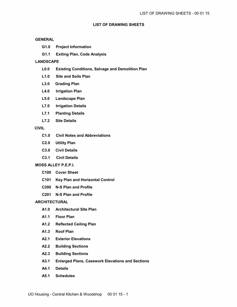
LIST OF DRAWING SHEETS
GENERAL
G1.0 Project Information
G1.1 Exiting Plan, Code Analysis
LANDSCAPE
L0.0 Existing Conditions, Salvage and Demolition Plan
L1.0 Site and Soils Plan
L3.0 Grading Plan
L4.0 Irrigation Plan
L5.0 Landscape Plan
L7.0 Irrigation Details
L7.1 Planting Details
L7.2 Site Details
CIVIL
C1.0 Civil Notes and Abbreviations
C2.0 Utility Plan
C3.0 Civil Details
C3.1 Civil Details
MOSS ALLEY P.E.P.I.
C100 Cover Sheet
C101 Key Plan and Horizontal Control
C200 N-S Plan and Profile
C201 N-S Plan and Profile
ARCHITECTURAL
A1.0 Architectural Site Plan
A1.1 Floor Plan
A1.2 Reflected Ceiling Plan
A1.3 Roof Plan
A2.1 Exterior Elevations
A2.2 Building Sections
A2.3 Building Sections
A3.1 Enlarged Plans, Casework Elevations and Sections
A4.1 Details
A5.1 Schedules
LIST OF DRAWING SHEETS - 00 01 15
UO Housing - Central Kitchen & Woodhsop 00 01 15 - 2
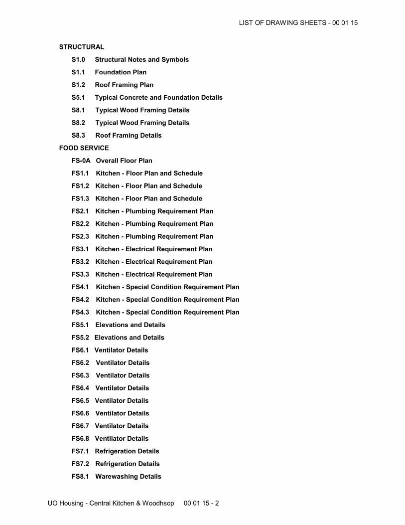
STRUCTURAL
S1.0 Structural Notes and Symbols
S1.1 Foundation Plan
S1.2 Roof Framing Plan
S5.1 Typical Concrete and Foundation Details
S8.1 Typical Wood Framing Details
S8.2 Typical Wood Framing Details
S8.3 Roof Framing Details
FOOD SERVICE
FS-0A Overall Floor Plan
FS1.1 Kitchen - Floor Plan and Schedule
FS1.2 Kitchen - Floor Plan and Schedule
FS1.3 Kitchen - Floor Plan and Schedule
FS2.1 Kitchen - Plumbing Requirement Plan
FS2.2 Kitchen - Plumbing Requirement Plan
FS2.3 Kitchen - Plumbing Requirement Plan
FS3.1 Kitchen - Electrical Requirement Plan
FS3.2 Kitchen - Electrical Requirement Plan
FS3.3 Kitchen - Electrical Requirement Plan
FS4.1 Kitchen - Special Condition Requirement Plan
FS4.2 Kitchen - Special Condition Requirement Plan
FS4.3 Kitchen - Special Condition Requirement Plan
FS5.1 Elevations and Details
FS5.2 Elevations and Details
FS6.1 Ventilator Details
FS6.2 Ventilator Details
FS6.3 Ventilator Details
FS6.4 Ventilator Details
FS6.5 Ventilator Details
FS6.6 Ventilator Details
FS6.7 Ventilator Details
FS6.8 Ventilator Details
FS7.1 Refrigeration Details
FS7.2 Refrigeration Details
FS8.1 Warewashing Details
LIST OF DRAWING SHEETS - 00 01 15
UO Housing - Central Kitchen & Woodhsop 00 01 15 - 3
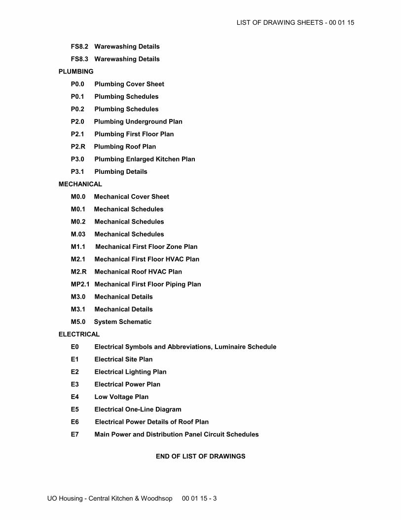
FS8.2 Warewashing Details
FS8.3 Warewashing Details
PLUMBING
P0.0 Plumbing Cover Sheet
P0.1 Plumbing Schedules
P0.2 Plumbing Schedules
P2.0 Plumbing Underground Plan
P2.1 Plumbing First Floor Plan
P2.R Plumbing Roof Plan
P3.0 Plumbing Enlarged Kitchen Plan
P3.1 Plumbing Details
MECHANICAL
M0.0 Mechanical Cover Sheet
M0.1 Mechanical Schedules
M0.2 Mechanical Schedules
M.03 Mechanical Schedules
M1.1 Mechanical First Floor Zone Plan
M2.1 Mechanical First Floor HVAC Plan
M2.R Mechanical Roof HVAC Plan
MP2.1 Mechanical First Floor Piping Plan
M3.0 Mechanical Details
M3.1 Mechanical Details
M5.0 System Schematic
ELECTRICAL
E0 Electrical Symbols and Abbreviations, Luminaire Schedule
E1 Electrical Site Plan
E2 Electrical Lighting Plan
E3 Electrical Power Plan
E4 Low Voltage Plan
E5 Electrical One-Line Diagram
E6 Electrical Power Details of Roof Plan
E7 Main Power and Distribution Panel Circuit Schedules
END OF LIST OF DRAWINGS
LIST OF DRAWING SHEETS - 00 01 15
UO Housing - Central Kitchen & Woodhsop 00 01 15 - 4
AVAILABLE PROJECT INFORMATION - 00 31 00
UO Housing - Central Kitchen & Woodshop 00 31 00 - 1
AVAILABLE PROJECT INFORMATION
PART 1 GENERAL
1.01 EXISTING CONDITIONS
A. Certain information relating to existing surface and subsurface conditions and structures isavailable to bidders but will not be part of the Contract Documents, as follows:
B. Geotechnical Report: Entitled Geotechnical Investigation, dated June 11, 2013 prepared by GRI.1. Copy is included in the Project Manual.2. This report identifies properties of below grade conditions and offers recommendations for
the design of foundations, prepared primarily for the use of Architect.3. The recommendations described shall not be construed as a requirement of this Contract,
unless specifically referenced in the Contract Documents.
PART 2 PRODUCTS (NOT USED)
PART 3 EXECUTION (NOT USED)
END OF AVAILABLE PROJECT INFORMATION
June 11, 2013 5454 GEOTECHNICAL RPT
University of Oregon University Planning Office 1295 Franklin Boulevard Eugene, OR 97403-1276 Attention: Martina Oxoby
SUBJECT: Geotechnical Investigation Central Kitchen and Woodshop University of Oregon Columbia Street Between E 17th and E 19th Avenues Eugene, Oregon
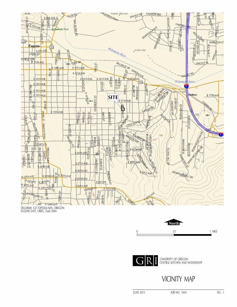
At your request, GRI has conducted a geotechnical investigation for the proposed central kitchen and woodshop on the University of Oregon (UO) campus in Eugene, Oregon. The general location of the site is shown on the Vicinity Map, Figure 1. The purpose of our investigation was to evaluate subsurface conditions at the site and develop conclusions and recommendations for site preparation, utilities, subdrainage, floor support, design and construction of foundations, and seismic design considerations. The investigation included subsurface explorations, laboratory testing, and engineering analyses. This report describes the work accomplished and summarizes our conclusions and recommendations for design and construction of the proposed project.
PROJECT DESCRIPTION
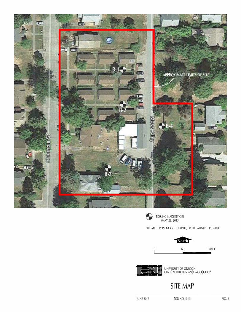
We understand the proposed structure will be up to two stories high and have a concrete slab-on-grade first floor at or near existing site grades. Although design of the structure is still in development, we anticipate maximum column and wall loads will be less than 200 kips and 3 kips/ft, respectively. The maximum height of cuts and fills to establish the structure will be minimal and generally less than 2 ft. The maximum depth of excavation for utilities is expected to be less than 10 ft. The limits of the proposed site are shown on the Site Map, Figure 2. We anticipate the new facility may include parking and access areas paved with asphaltic concrete.
SITE DESCRIPTION Topography and Surface Conditions
The site is located in the central portion of the block bordered by Columbia and Moss streets and East 17th and 19th avenues. The gravel-surfaced Moss Alley cuts through the eastern portion of the site. The site is currently occupied by single-family housing and associated sidewalks, driveways, and yards. Available topographic information indicates the site slopes is relatively flat and lies at about elevation 455 ft.
Geology
The site is mantled with predominantly fine-grained soils derived from the weathering of volcaniclastic mudstone. Beneath the decomposed mudstone, the site is underlain by Oligocene-age, fine-grained
2
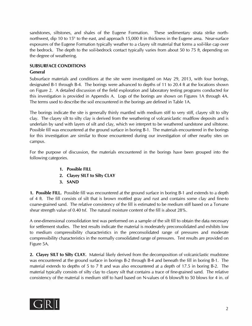
sandstones, siltstones, and shales of the Eugene Formation. These sedimentary strata strike north-northwest, dip 10 to 15 to the east, and approach 15,000 ft in thickness in the Eugene area. Near-surface exposures of the Eugene Formation typically weather to a clayey silt material that forms a soil-like cap over the bedrock. The depth to the soil-bedrock contact typically varies from about 50 to 75 ft, depending on the degree of weathering.
SUBSURFACE CONDITIONS General
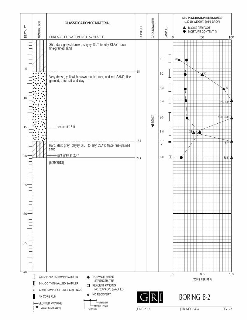
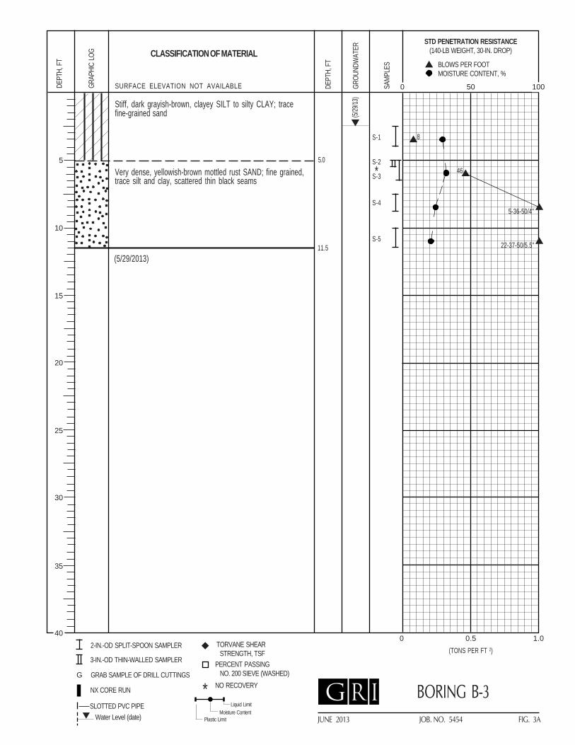
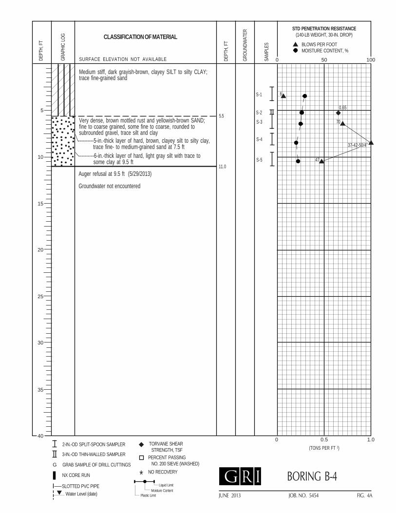
Subsurface materials and conditions at the site were investigated on May 29, 2013, with four borings, designated B-1 through B-4. The borings were advanced to depths of 11 to 20.4 ft at the locations shown on Figure 2. A detailed discussion of the field exploration and laboratory testing programs conducted for this investigation is provided in Appendix A. Logs of the borings are shown on Figures 1A through 4A. The terms used to describe the soil encountered in the borings are defined in Table 1A.
The borings indicate the site is generally thinly mantled with medium stiff to very stiff, clayey silt to silty clay. The clayey silt to silty clay is derived from the weathering of volcaniclastic mudflow deposits and is underlain by sand with layers of silt and clay, which we interpret to be weathered sandstone and siltstone. Possible fill was encountered at the ground surface in boring B-1. The materials encountered in the borings for this investigation are similar to those encountered during our investigation of other nearby sites on campus.
For the purpose of discussion, the materials encountered in the borings have been grouped into the following categories.
1. Possible FILL 2. Clayey SILT to Silty CLAY 3. SAND
1. Possible FILL. Possible fill was encountered at the ground surface in boring B-1 and extends to a depth of 4 ft. The fill consists of silt that is brown mottled gray and rust and contains some clay and fine-to coarse-grained sand. The relative consistency of the fill is estimated to be medium stiff based on a Torvane shear strength value of 0.40 tsf. The natural moisture content of the fill is about 28%.
A one-dimensional consolidation test was performed on a sample of the silt fill to obtain the data necessary for settlement studies. The test results indicate the material is moderately preconsolidated and exhibits low to medium compressibility characteristics in the preconsolidated range of pressures and moderate compressibility characteristics in the normally consolidated range of pressures. Test results are provided on Figure 5A.
2. Clayey SILT to Silty CLAY. Material likely derived from the decomposition of volcaniclastic mudstone was encountered at the ground surface in borings B-2 through B-4 and beneath the fill in boring B-1. The material extends to depths of 5 to 7 ft and was also encountered at a depth of 17.5 in boring B-2. The material typically consists of silty clay to clayey silt that contains a trace of fine-grained sand. The relative consistency of the material is medium stiff to hard based on N-values of 6 blows/ft to 50 blows for 4 in. of
3
sampler penetration and a Torvane shear strength value of 0.65 tsf. The natural moisture content of the material ranges from about 14 to 29%. Boring B-2 was terminated in this unit at a depth of 20.4 ft.
3. SAND. Yellowish-brown mottled rust, white, and red, fine-grained sand, likely derived from the weathering of the siltstone and sandstone that underlies the site was encountered at depths of 5 to 7 ft in borings B-1 through B-4. The sand in boring B-4 contains gravel-size rock fragment, relict rock structure, and thin layers of silt and clay. Based on N-values of 24 blows/ft to 50 blows for 1 in. of sampler penetration, the relative density of the sand is estimated to be medium dense to very dense. The natural moisture content of the sand ranges from 21 to 46%. Borings B-1, B-3, and B-4 were terminated in sand at depths of 11 to 16.3 ft.
Groundwater
Groundwater was encountered during drilling at depths of 4.5, 15, and 2.5 ft in borings B-1, B-2, and B-3, respectively. Groundwater was not encountered in boring B-4.
Near the end of drilling, the groundwater level in boring B-2 rose to near the ground surface before the auger was removed. Immediately after removing the auger, groundwater in the borehole was measured at a depth of 17.5 ft. The borehole was left open throughout the day and groundwater was measured at a depth of 9.3 ft about 5 hours after the auger was removed. We anticipate much of the groundwater yield is due to the zone of dense sand encountered at a depth of 15 ft in boring B-2.
Based on our experience with other nearby projects, we understand that the local groundwater level typically ranges from about 5 to 15 ft below the ground surface. However, due to the presence of shallow, low-permeability subsurface materials, perched groundwater conditions approaching the ground surface could occur during the wet, winter months and following periods of intense precipitation.
CONCLUSIONS AND RECOMMENDATIONS General
The borings indicate the site is generally mantled with clayey silt to silty clay that is underlain by sand. The native materials encountered in the borings were likely derived from the decomposition of mudstone, sandstone, and siltstone. We anticipate that the groundwater level at the site will fluctuate with precipitation, approaching the ground surface during the wet season and lowest at the end of the dry season. Our experience indicates the soils that mantle the site are sensitive to moisture and are easily disturbed by construction activities when wet.
The important geotechnical aspects relating to earthwork and design and construction of foundations at this site include a seasonally high groundwater table, the moisture-sensitive and compressible nature of the fine-grained soils, and the potential presence of fill. The following sections of this report provide our conclusions and recommendations regarding site preparation, utility construction, and design and construction of foundations, floor support, embedded walls, and pavements for the project.
Site Preparation
The ground surface within all building areas, paved areas, walkways, and other areas to receive structure, should be stripped of existing pavement, vegetation, surface organics, and loose surface soils. In our opinion, all non-organic debris should be removed from the site. Organic strippings should be disposed of
4
off-site or stockpiled on site for use in landscaped areas. Following stripping or excavation to subgrade level, the exposed subgrade should be evaluated to identify any soft areas that may require overexcavation. Proof rolling with a loaded dump truck may be part of this evaluation. Soft or loose areas disclosed by the evaluation should be overexcavated to firm material and backfilled with structural fill. Particular attention should be paid to any areas of possible uncontrolled fill exposed during site preparation. It may be necessary to excavate several test pits in these areas to document the extent, thickness, and condition of existing fill and determine whether additional overexcavation is necessary to remove soft, loose, or deleterious materials. A qualified geotechnical engineer or engineering geologist should observe the proof rolling and fill removal.
It has been our experience that the moisture content of the upper few feet of the silty soils will decrease during extended warm, dry weather. However, below this depth, the moisture content of the soil tends to remain relatively unchanged and well above the optimum moisture content for compaction. As a result, the contractor must use construction equipment and procedures that prevent disturbance and softening of the subgrade soils. To prevent disturbance of the moisture-sensitive silt soils, site grading should be completed using a track-mounted hydraulic excavator. The excavation should be finished using a smooth-edged bucket to produce a firm, undisturbed surface. It may also be necessary to construct granular haul roads and work pads concurrently with excavation to minimize subgrade disturbance. If the subgrade is disturbed during construction, soft, disturbed soils should be overexcavated to firm soil and backfilled with structural fill.
If construction occurs during wet ground conditions, the use of imported granular material will be required for filling to protect the underlying silt subgrade and provide a firm working surface for construction activities. In our opinion, a 12- to 18-in.-thick granular work pad should be sufficient to prevent disturbance of the subgrade by lighter construction equipment and limited traffic by dump trucks. Haul roads and other high-density traffic areas will require a minimum of 18 to 24 in. of fragmental rock, up to 6-in. nominal size, to reduce the risk of subgrade deterioration. The use of a geotextile fabric over the subgrade may reduce maintenance during construction. Haul roads can also be constructed by placing a thickened section of pavement crushed rock base course (CRB) and subsequently spreading and grading the excess CRB after earthwork is complete.
Utilities
The method of excavation and the design of trench support are the responsibility of the contractor and subject to applicable local, state, and federal safety regulations, including the current OSHA excavation and trench safety standards. The means, methods, and sequencing of construction operations and site safety are also the responsibility of the contractor. The information provided below is for the use of our client and should not be interpreted to mean that we are assuming responsibility for the contractor’s actions or site safety.
According the current OSHA regulations, the materials encountered in the borings at this site may be classified as Type B. In our opinion, trenches less than 4 ft deep may be cut vertically and left unsupported during the normal construction sequence, i.e., assuming trenches are excavated and backfilled in the shortest possible sequence, and excavations are not allowed to remain open longer than 8 hrs. Excavations that are more than 4 ft deep should be laterally supported or alternatively provided with stable side slopes
5
of 1H:1V or flatter. In our opinion, adequate lateral support may be provided by common methods, such as the use of a trench shield or hydraulic shoring systems.
All backfill placed in utility trench excavations within the limits of the building, pavement areas, sidewalks, and any other area of structure, should consist of sand, sand and gravel, or crushed rock with a maximum size of up to 11/2 in. and not more than about 5% passing the No. 200 sieve (washed analysis). In our opinion, the granular backfill should be placed in 9-in.-thick lifts (loose) and compacted using vibratory plate compactors or tamping units to at least 95% of the maximum dry density as determined by ASTM D 698. If heavier compaction equipment (e.g., a hoepack) is used, 12- to 24-in.-thick lifts may be appropriate. Flooding or jetting the backfilled trenches with water to achieve the recommended compaction should not be permitted. Dewatering of utility trenches will also depend on groundwater levels at the time of construction. Overexcavation of trench bottoms may be necessary to place granular stabilization material and to facilitate dewatering.
Structural Fill
It is anticipated that a relatively minor amount of structural fill may be required to establish site grades. In our opinion, imported granular material would be most suitable for construction of the structural fills. Granular material such as sand, sandy gravel, or fragmental rock with a maximum size of about 2 in. and with not more than about 5% passing the No. 200 sieve (washed analysis), would be suitable structural fill material. Granular fill should be placed in up to 12-in.-thick (loose) lifts and compacted with a medium-weight (48-in.-diameter drum), smooth, steel-wheeled, vibratory roller to at least 95% of the maximum dry density as determined by ASTM D 698.
The natural moisture content of the on-site soils will likely exceed the optimum moisture content throughout the majority of the year; therefore, some aeration and drying will be required to meet the requirements for proper compaction. The required drying can best be accomplished during dry weather by spreading the material in thin lifts and disking. Fine-grained soils used as structural fill should be placed in up to 9-in.-thick lifts (loose) and compacted with segmented-pad or sheepsfoot rollers. If fine-grained fill soils are compacted at a moisture content wetter than recommended, it will be difficult to achieve the specified densities, and may result in fill that is relatively weak and compressible.
On-site, fine-grained soils and site strippings that are free of debris may be used as fill in landscaped areas. These materials should be placed at about 90% of the maximum dry density as determined by ASTM D 698. The moisture content of soils placed in landscaped areas is not as critical, provided that construction equipment can effectively handle the materials.
Subdrainage and Floor Support
We understand the floor of the proposed building will be established near existing site grades. To provide uniform floor support and a capillary break between the subgrade soils and the floor slabs, we recommend the installation of a minimum 8-in.-thick granular base course beneath the floor slabs. This should be considered a minimum thickness for structural support considerations. In areas where construction equipment will operate on the rock, a thicker section will likely be required. The base course material should consist of fragmental rock of up to 11/2 in. and have less than 2% passing the No. 200 sieve (washed analysis), 3/4- to1/4-in. crushed rock would be suitable for this purpose. Prior to installation of the base course, the subgrade should be evaluated, possibly by proof rolling with a loaded dump truck. Soft areas
6
detected during the evaluation should be overexcavated and replaced with granular structural fill. The base course material should be installed in a single lift and compacted as structural fill. In addition, it may be appropriate to install a suitable vapor-retarding membrane beneath slab-on-grade floors in moisture-sensitive storage areas, or areas that will have floor coverings.
If moisture-sensitive flooring will be placed on the floor slab, it may be appropriate to install a suitable vapor-retarding membrane beneath slab-on-grade floors. The membrane should be installed in accordance with the manufacturer’s recommendations.
Foundations
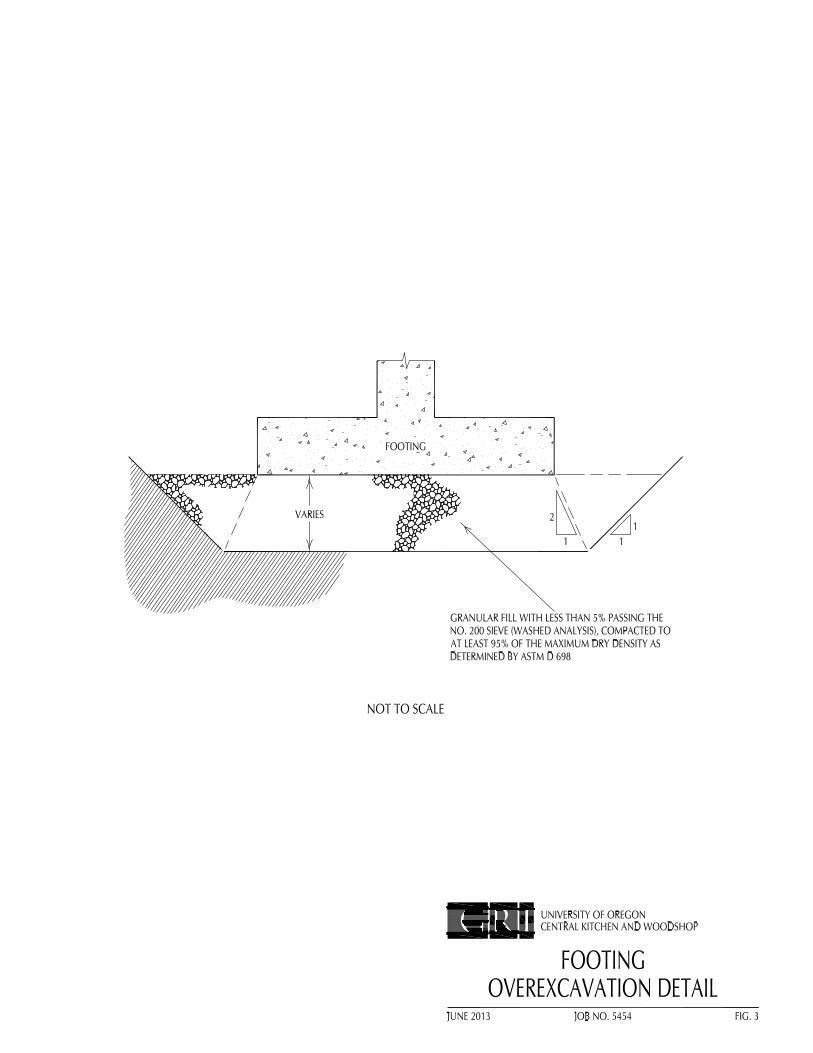
Foundation support for the building can be provided by conventional wall- and column-type spread footings. Footings should be established in firm, undisturbed soil or compacted structural fill at a minimum depth of 11/2 ft below the lowest adjacent finished grade. The width of footings should not be less that 18 in. for wall footings or 24 in. for isolated column footings. During wet weather, a 3-in. -thick layer of 3/4- in.-minus crushed rock should be placed in the bottom of footing excavations to minimize disturbance of the silty foundation soils. We anticipate the bearing value used for footing design will be limited by settlement rather than bearing capacity considerations. Footings established in accordance with the criteria above can be designed on the basis of an allowable soil bearing pressure of 2,000 psf. This value applies to the total of dead load plus frequently and/or permanently applied live loads and can be increased by one-half for the total of all loads; dead, live, and wind or seismic. Where fill is encountered at footing subgrade, the material should be evaluated by a qualified geotechnical engineer. Where the footing subgrade is underlain by fill, the fill should be overexcavated to competent native material, or a maximum of 2 ft. If softer fill soils extend below the recommended depth of overexcavation, we recommend removing the soft fill to competent material. The overexcavation should be accomplished in accordance with the guidelines provided on Figure 3 and backfilled with granular structural fill as described in Structural Fill section of this report. For estimating purposes, it should be assumed that about half of the building foundations will encounter fill at subgrade elevation.
We estimate the total settlement of spread footings designed in accordance with the recommendations presented above will be less than 1 in. Differential settlements between adjacent footings should be less than half the total settlement. Past experience indicates that these settlements will occur rapidly, with the majority of the settlement occurring during construction.
Horizontal shear forces can be resisted partially or completely by frictional forces developed between the base of spread footings and the underlying soil. The total shearing resistance between the foundation footprint and the soil should be taken as the normal force, i.e., the sum of all vertical forces (dead load plus real live load) times the coefficient of friction between the soil and the base of the footing. We recommend an ultimate value of 0.35 for the coefficient of friction for footings cast on undisturbed fine-grained soil. For footings cast on granular structural fill, the coefficient of friction can be increased to 0.40. If additional lateral resistance is required, passive earth pressures against embedded footings or walls can be computed using a hydrostatic pressure based on an equivalent fluid with a unit weight of 250 pcf. This design passive earth pressure would be effective only if granular structural fill is used for the backfill.
7
Lateral Earth Pressures
Design lateral earth pressures for embedded walls, such as for a loading dock, depend on the type of construction, i.e., the ability of the wall to yield. The two possible conditions are 1) a wall that is laterally supported at floor levels or its top and, therefore, is unable to yield, and 2) a conventional cantilevered retaining wall, which yields by tilting about its base. Non-yielding walls should be designed using an equivalent fluid pressure of 45 pcf. Walls that are allowed to yield by tilting about their base should be designed using an equivalent fluid pressure of 35 pcf. Horizontal pressures due to seismic loads may be estimated on the basis of an equivalent fluid having a unit weight of 18 pcf. The resultant of the seismic force acts at a distance of 0.6H above the base of the wall, where H is the height of the wall.
The lateral earth pressure criteria described above assume the embedded walls will be backfilled with clean, free-draining, granular material. Wall backfill material should consist of medium-grained sand, sand and gravel, or well-graded gravel, with not more than 2% passing the No. 200 sieve (washed analysis). A minimum 24-in.-thick drainage blanket should be placed from top to bottom against the embedded. The granular backfill should be placed in lifts not to exceed 9 in. (loose) and compacted to about 93% of the maximum dry density (ASTM D 698). Compaction close to the walls should be accomplished using hand-operated, vibratory plate compactors. Overcompaction of the backfill should be avoided. Heavy compactors and large pieces of construction equipment should be kept a minimum distance of 5 ft away from any embedded wall to avoid excessive lateral pressures.
Pavement Section
It has been our experience with similar projects on campus that 3 in. of asphaltic concrete (AC) over 8 in. of crushed rock base course (CRB) is suitable for the support of automobile traffic and parking areas. The pavement section should consist of at least 4 in. of AC over 12 in. of CRB in areas that will be subjected to heavy truck traffic. These design sections assume the subgrade consists of firm, undisturbed silty soils or compacted structural fill. The recommended thicknesses assume all pavement sections will be constructed during the dry season. If wet-weather pavement construction is considered, it will likely be necessary to increase the thickness of CRB for all pavement sections to support construction equipment.
Seismic Considerations
Based on our review of the 2009 International Building Code (IBC) and 2010 Oregon Structural Specialty Code, we recommend using Site Class D to evaluate the seismic design of the structure. The IBC design methodology uses two spectral response coefficients, SS and S1, corresponding to periods of 0.2 and 1.0 seconds, to develop the design earthquake spectrum. The SS and S1 coefficients identified for the site are 0.665 and 0.326 g, respectively.
Based on the plasticity, high fines content, strength of the soils encountered in the borings completed by GRI at the site and at nearby sites, and the anticipated ground motions, it is our opinion the risk of liquefaction of the soils below the groundwater level is very low. Based on the proximity of the site to mapped active faults, the risk of surface rupture due to faulting is very low. The risk of tsunami inundation at the site is absent. Due to the horizontal distance of the site from a saturated sloping free face, we estimate the risk of lateral spreading and slope instability for the building site is very low.
8
Renews 12/2014
LIMITATIONS
This report has been prepared to aid the architect and engineer in the design of this project. The scope is limited to the specific project and location described herein, and our description of the project represents our understanding of the significant aspects of the project relevant to the design and construction of the earthwork, floor support, foundations, and pavements. In the event that any changes in the design and location of the project elements as outlined in this report are planned, we should be given the opportunity to review the changes and to modify or reaffirm the conclusions and recommendations of this report in writing.
The conclusions and recommendations submitted in this report are based on the data obtained from the borings made at the locations indicated on Figure 2 and from other sources of information discussed in this report. In the performance of subsurface investigations, specific information is obtained at specific locations at specific times. However, it is acknowledged that variations in soil conditions may exist between boring locations. This report does not reflect any variations that may occur between these explorations. The nature and extent of variation may not become evident until construction. If, during construction, subsurface conditions different from those encountered in the explorations are observed or encountered, we should be advised at once so that we can observe and review these conditions and reconsider our recommendations where necessary.
Please contact the undersigned if you have any questions or comments regarding this report.
Submitted for GRI, Michael W. Reed, PE Gene M. Tupper, PE, GE Principal Senior Engineer
This document has been submitted electronically.
G R I
VICINITY MAP
JUNE 2013 JOB NO. 5454 FIG. 1
0 1/2 1 MILE
North
UNIVERSITY OF OREGONCENTRAL KITCHEN AND WOODSHOP
DELORME 3-D TOPOQUADS, OREGONEUGENE EAST, OREG. (3ad) 2004
A-1
APPENDIX A
FIELD EXPLORATIONS AND LABORATORY TESTING
FIELD EXPLORATIONS
Subsurface materials and conditions at the site were investigated on May 29, 2013, with four borings, designated B-1 through B-4. The borings were drilled with solid stem auger methods using a trailer-mounted Simco 2400 SK drill rig provided and operated by Greg Vandehey Soil Sampling, of Forest Grove, Oregon. All drilling and sampling operations were observed by an experienced geotechnical engineer from GRI, who maintained a detailed log of the materials disclosed during the course of the work.
The borings were advanced to depths of 11 to 20.4 ft at the locations shown on Figure 2. Disturbed and undisturbed soil samples were obtained from the borings at approximately 2.5-ft intervals of depth. Disturbed soil samples were obtained using a standard split-spoon sampler. The Standard Penetration Test (SPT) was conducted while obtaining disturbed soil samples. This test is performed by driving a split-spoon sampler into the soil a distance of 18 in. using the force of a 140-lb hammer dropped 30 in. The number of blows required to drive the sampler the last 12 in. is called the Standard Penetration Resistance, or N-value. The N-value provides a measure of the relative density of granular soils, such as sand, and the relative consistency or stiffness of cohesive soils, such as silt. In addition, a relatively undisturbed 3.0-in.-diameter Shelby tube sample was taken at selected intervals in the silt soil. The sample was obtained by pushing a Shelby tube into the undisturbed soil a distance of approximately 24 in. using the hydraulic ram of the drill rig. The soil exposed in the ends of the Shelby tube was examined and classified. After classification, the tube was sealed with rubber caps and tape and returned to our laboratory for further classification and testing.
Logs of the borings are provided on Figures 1A through 4A. Each log presents a descriptive summary of the various types of material encountered in the boring and notes the depth where the materials and/or characteristics of the materials change. To the right of the descriptive summary, the numbers and types of samples collected during the drilling operation are indicated. Farther to the right, N-values are shown graphically along with moisture contents, Torvane shear strength values, and the percent passing the No. 200 sieve. The terms used to describe the soils encountered in the borings are defined in Table 1A.
LABORATORY TESTING General
The samples obtained from the borings were examined in our laboratory where the physical characteristics of the samples were noted, and the field classifications were modified where necessary. At the time of classification, the natural moisture content of each sample was determined.
Natural Moisture Content
Natural moisture contents were determined in conformance with ASTM D 2216. The results are summarized on Figures 1A through 4A.
A-2
Torvane Shear Strength
The approximate undrained shear strength of relatively undisturbed fine-grained soil samples was determined using a Torvane shear device. The Torvane is a hand-held apparatus with vanes which are inserted into the soil. The torque required to fail the soil in shear around the vanes is measured using a calibrated spring. The results of the Torvane shear tests are shown on Figures 1A and 4A.
Unit Weight
The dry unit weight, or density, of an undisturbed soil sample was determined in the laboratory in substantial conformance with ASTM D 2937. Sample S-1 from boring B-1 has a dry unit weight of 97 pcf and natural moisture content of 28%.
One-Dimensional Consolidation Test
A one-dimensional consolidation test was performed in conformance with ASTM D 2435 on relatively undisturbed sample S-1 obtained from a depth of 3 ft in boring B-1. The test provides data on the compressibility of the underlying fine-grained soils, necessary for settlement studies. The test results are summarized on Figure 5A in the form of a curve showing percent strain versus applied effective stress. The initial and final dry unit weight and moisture content of the sample are also shown on the figure.
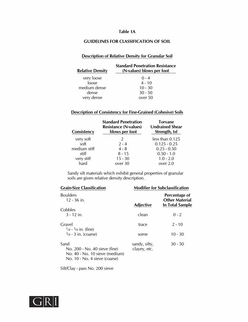
Table 1A
GUIDELINES FOR CLASSIFICATION OF SOIL
Description of Relative Density for Granular Soil
Standard Penetration Resistance Relative Density (N-values) blows per foot
very loose 0 - 4 loose 4 - 10
medium dense 10 - 30 dense 30 - 50
very dense over 50
Description of Consistency for Fine-Grained (Cohesive) Soils
Standard Penetration Torvane Resistance (N-values) Undrained Shear
Consistency blows per foot Strength, tsf
very soft 2 less than 0.125 soft 2 - 4 0.125 - 0.25
medium stiff 4 - 8 0.25 - 0.50 stiff 8 - 15 0.50 - 1.0
very stiff 15 - 30 1.0 - 2.0 hard over 30 over 2.0
Sandy silt materials which exhibit general properties of granular soils are given relative density description.
Grain-Size Classification Modifier for Subclassification
Boulders Percentage of 12 - 36 in. Other Material Adjective In Total Sample Cobbles 3 - 12 in. clean 0 - 2 Gravel trace 2 - 10 1/4 - 3/4 in. (fine) 3/4 - 3 in. (coarse) some 10 - 30 Sand sandy, silty, 30 - 50 No. 200 - No. 40 sieve (fine) clayey, etc. No. 40 - No. 10 sieve (medium) No. 10 - No. 4 sieve (coarse) Silt/Clay - pass No. 200 sieve
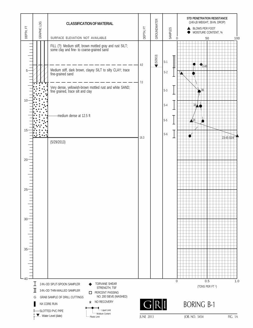
CLASSIFICATION OF MATERIALDE
PTH,
FT
2-IN.-OD SPLIT-SPOON SAMPLER
3-IN.-OD THIN-WALLED SAMPLER
TORVANE SHEAR STRENGTH, TSF
PERCENT PASSING NO. 200 SIEVE (WASHED)NO RECOVERY*
GRAP
HIC
LOG
GROU
NDW
ATER
DEPT
H, F
T
SAMP
LES
Water Level (date)SLOTTED PVC PIPE
NX CORE RUN
GRAB SAMPLE OF DRILL CUTTINGS
Liquid Limit
Plastic LimitMoisture Content
STD PENETRATION RESISTANCE(140-LB WEIGHT, 30-IN. DROP)
BLOWS PER FOOTMOISTURE CONTENT, %
G
0 0.5 1.0(TONS PER FT 2)
0 50 100
G R I
5
10
15
25
30
35
40
20
SURFACE ELEVATION NOT AVAILABLE
BORING B-1
JUNE 2013 JOB. NO. 5454 FIG. 1A
S-2
S-5
S-6
S-1
(5/29/2013)16.3
S-3
S-4
7
36
34
24
23-45-50/4"
FILL (?): Medium stiff, brown mottled gray and rust SILT;some clay and fine- to coarse-grained sand
Medium stiff, dark brown, clayey SILT to silty CLAY; tracefine-grained sand
Very dense, yellowish-brown mottled rust and white SAND;fine grained, trace silt and clay
(5/29
/13)
4.0
7.0
0.40
----------medium dense at 12.5 ft
CLASSIFICATION OF MATERIALDE
PTH,
FT
2-IN.-OD SPLIT-SPOON SAMPLER
3-IN.-OD THIN-WALLED SAMPLER
TORVANE SHEAR STRENGTH, TSF
PERCENT PASSING NO. 200 SIEVE (WASHED)NO RECOVERY*
GRAP
HIC
LOG
GROU
NDW
ATER
DEPT
H, F
T
SAMP
LES
Water Level (date)SLOTTED PVC PIPE
NX CORE RUN
GRAB SAMPLE OF DRILL CUTTINGS
Liquid Limit
Plastic LimitMoisture Content
STD PENETRATION RESISTANCE(140-LB WEIGHT, 30-IN. DROP)
BLOWS PER FOOTMOISTURE CONTENT, %
G
0 0.5 1.0(TONS PER FT 2)
0 50 100
G R I
5
10
15
25
30
35
40
20
SURFACE ELEVATION NOT AVAILABLE
BORING B-2
JUNE 2013 JOB. NO. 5454 FIG. 2A
S-2
S-5
S-6
S-1
S-8
10
(5/29/2013)20.4
S-3
S-7*
S-4
50
87
22-50/6"
39-36-50/6"
35
50/1"
50/5"
Stiff, dark grayish-brown, clayey SILT to silty CLAY; tracefine-grained sand
Very dense, yellowish-brown mottled rust, and red SAND; finegrained, trace silt and clay
Hard, dark gray, clayey SILT to silty CLAY; trace fine-grainedsand
(5/29
/13)
5.5
17.5
----------dense at 15 ft
----------light gray at 20 ft
CLASSIFICATION OF MATERIALDE
PTH,
FT
2-IN.-OD SPLIT-SPOON SAMPLER
3-IN.-OD THIN-WALLED SAMPLER
TORVANE SHEAR STRENGTH, TSF
PERCENT PASSING NO. 200 SIEVE (WASHED)NO RECOVERY*
GRAP
HIC
LOG
GROU
NDW
ATER
DEPT
H, F
T
SAMP
LES
Water Level (date)SLOTTED PVC PIPE
NX CORE RUN
GRAB SAMPLE OF DRILL CUTTINGS
Liquid Limit
Plastic LimitMoisture Content
STD PENETRATION RESISTANCE(140-LB WEIGHT, 30-IN. DROP)
BLOWS PER FOOTMOISTURE CONTENT, %
G
0 0.5 1.0(TONS PER FT 2)
0 50 100
G R I
5
10
15
25
30
35
40
20
SURFACE ELEVATION NOT AVAILABLE
BORING B-3
JUNE 2013 JOB. NO. 5454 FIG. 3A
S-2*
S-1 8
(5/29/2013)11.5
S-3
S-4
46
5-36-50/4"
S-522-37-50/5.5"
Stiff, dark grayish-brown, clayey SILT to silty CLAY; tracefine-grained sand
Very dense, yellowish-brown mottled rust SAND; fine grained,trace silt and clay, scattered thin black seams
(5/29
/13)
5.0
CLASSIFICATION OF MATERIALDE
PTH,
FT
2-IN.-OD SPLIT-SPOON SAMPLER
3-IN.-OD THIN-WALLED SAMPLER
TORVANE SHEAR STRENGTH, TSF
PERCENT PASSING NO. 200 SIEVE (WASHED)NO RECOVERY*
GRAP
HIC
LOG
GROU
NDW
ATER
DEPT
H, F
T
SAMP
LES
Water Level (date)SLOTTED PVC PIPE
NX CORE RUN
GRAB SAMPLE OF DRILL CUTTINGS
Liquid Limit
Plastic LimitMoisture Content
STD PENETRATION RESISTANCE(140-LB WEIGHT, 30-IN. DROP)
BLOWS PER FOOTMOISTURE CONTENT, %
G
0 0.5 1.0(TONS PER FT 2)
0 50 100
G R I
5
10
15
25
30
35
40
20
SURFACE ELEVATION NOT AVAILABLE
BORING B-4
JUNE 2013 JOB. NO. 5454 FIG. 4A
Auger refusal at 9.5 ft (5/29/2013)
Groundwater not encountered
11.0
S-2
S-1 6
S-3
S-4
70
37-42-50/4"
S-5 47
Medium stiff, dark grayish-brown, clayey SILT to silty CLAY;trace fine-grained sand
Very dense, brown mottled rust and yellowish-brown SAND;fine to coarse grained, some fine to coarse, rounded tosubrounded gravel, trace silt and clay
5.5
----------5-in.-thick layer of hard, brown, clayey silt to silty clay,trace fine- to medium-grained sand at 7.5 ft
----------6-in.-thick layer of hard, light gray silt with trace tosome clay at 9.5 ft
0.65
SUMMARY - 01 10 00
UO Housing - Central Kitchen & Woodshop 01 10 00 - 1
SUMMARY
PART 1 GENERAL
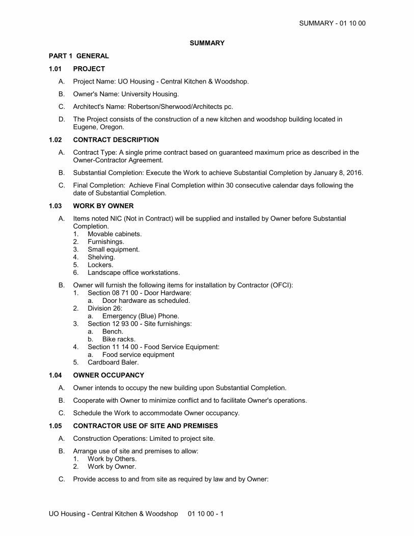
1.01 PROJECT
A. Project Name: UO Housing - Central Kitchen & Woodshop.
B. Owner's Name: University Housing.
C. Architect's Name: Robertson/Sherwood/Architects pc.
D. The Project consists of the construction of a new kitchen and woodshop building located inEugene, Oregon.
1.02 CONTRACT DESCRIPTION
A. Contract Type: A single prime contract based on guaranteed maximum price as described in theOwner-Contractor Agreement.
B. Substantial Completion: Execute the Work to achieve Substantial Completion by January 8, 2016.
C. Final Completion: Achieve Final Completion within 30 consecutive calendar days following thedate of Substantial Completion.
1.03 WORK BY OWNER
A. Items noted NIC (Not in Contract) will be supplied and installed by Owner before SubstantialCompletion. 1. Movable cabinets.2. Furnishings.3. Small equipment.4. Shelving.5. Lockers.6. Landscape office workstations.
B. Owner will furnish the following items for installation by Contractor (OFCI):1. Section 08 71 00 - Door Hardware:
a. Door hardware as scheduled.2. Division 26:
a. Emergency (Blue) Phone.3. Section 12 93 00 - Site furnishings:
a. Bench.b. Bike racks.
4. Section 11 14 00 - Food Service Equipment:a. Food service equipment
5. Cardboard Baler.
1.04 OWNER OCCUPANCY
A. Owner intends to occupy the new building upon Substantial Completion.
B. Cooperate with Owner to minimize conflict and to facilitate Owner's operations.
C. Schedule the Work to accommodate Owner occupancy.
1.05 CONTRACTOR USE OF SITE AND PREMISES
A. Construction Operations: Limited to project site.
B. Arrange use of site and premises to allow:1. Work by Others.2. Work by Owner.
C. Provide access to and from site as required by law and by Owner:
SUMMARY - 01 10 00
UO Housing - Central Kitchen & Woodhsop 01 10 00 - 2
1. Emergency Building Exits During Construction: Keep all exits required by code open duringconstruction period; provide temporary exit signs if exit routes are temporarily altered.
2. Do not obstruct roadways, sidewalks, or other public ways without permit.
PART 2 PRODUCTS - NOT USED
PART 3 EXECUTION - NOT USED
END OF SECTION
ADMINISTRATIVE REQUIREMENTS - 01 30 00
UO Housing - Central Kitchen & Woodshop 01 30 00 - 1
ADMINISTRATIVE REQUIREMENTS
PART 1 GENERAL
1.01 SECTION INCLUDES
A. Electronic document submittal process.
B. Preconstruction meeting.
C. Site mobilization meeting.
D. Progress meetings.
E. Progress photographs.
F. Coordination drawings.
G. Submittals for review, information, and project closeout.
H. Number of copies of submittals.
I. Submittal procedures.
1.02 RELATED REQUIREMENTS
A. Document 00 72 00 - General Conditions: Dates for applications for payment.
B. Section 01 10 00 - Summary: Summary of Work.
C. Section 01 70 00 - Execution and Closeout Requirements: Additional coordination requirements.
D. Section 01 78 00 - Closeout Submittals: Project record documents.
PART 2 PRODUCTS - NOT USED
PART 3 EXECUTION
3.01 ELECTRONIC DOCUMENT SUBMITTAL PROCESS
A. All documents transmitted for purposes of administration of the contract are to be in electronic(PDF) format and transmitted via email.1. Besides submittals for review, information, and closeout, this procedure applies to requests
for information (RFIs), progress documentation, contract modification documents (e.g.supplementary instructions, change proposals, change orders), applications for payment,field reports and meeting minutes, and any other document any participant wishes to makepart of the project record.
2. It is Contractor's responsibility to submit documents in PDF format.3. Unless approved in advance by the Architect, paper document transmittals will not be
reviewed.4. All other specified submittal and document transmission procedures apply, except that
electronic document requirements do not apply to samples or color selection charts.
3.02 PRECONSTRUCTION MEETING
A. Owner will schedule a meeting after Notice to Proceed.
B. Attendance Required:1. Owner.2. Owner's Project Manager.3. Architect.4. Contractor.5. Major Subcontractors.
C. Agenda:1. Submission of list of Subcontractors, list of Products, schedule of values, and progress
schedule.
ADMINISTRATIVE REQUIREMENTS - 01 30 00
UO Housing - Central Kitchen & Woodhsop 01 30 00 - 2
2. Designation of personnel representing the parties to Contract and Architect.3. Designation of personnel representing the parties to Contract and Architect.4. Procedures and processing of field decisions, submittals, substitutions, applications for
payments, proposal request, Change Orders, and Contract closeout procedures.5. Scheduling.6. Use of premises by Owner and Contractor.7. Owner's requirements and occupancy prior to completion.8. Construction facilities and controls provided by Owner.9. Temporary utilities provided by Owner.10. Security and housekeeping procedures.11. Schedules.12. Application for payment procedures.13. Procedures for testing.14. Procedures for maintaining record documents.15. Requirements for start-up of equipment.16. Inspection and acceptance of equipment put into service during construction period.
D. Record minutes and distribute copies within two days after meeting to participants, with copies toArchitect, Owner, participants, and those affected by decisions made.
3.03 PROGRESS MEETINGS
A. Schedule and administer meetings throughout progress of the Work at maximum weeklyintervals.
B. Make arrangements for meetings, prepare agenda with copies for participants, preside atmeetings.
C. Attendance Required: Job superintendent, major Subcontractors and suppliers, Owner, Owner'sProject Manager, Architect, as appropriate to agenda topics for each meeting.
D. Agenda:1. Review minutes of previous meetings.2. Review of Work progress.3. Field observations, problems, and decisions.4. Identification of problems that impede, or will impede, planned progress.5. Review of submittals schedule and status of submittals.6. Review of off-site fabrication and delivery schedules.7. Maintenance of progress schedule.8. Corrective measures to regain projected schedules.9. Planned progress during succeeding work period.10. Coordination of projected progress.11. Maintenance of quality and work standards.12. Effect of proposed changes on progress schedule and coordination.13. Other business relating to Work.
E. Record minutes and distribute copies within two days after meeting to participants, with copies toArchitect, Owner, participants, and those affected by decisions made.
3.04 PROGRESS PHOTOGRAPHS
A. Submit photographs with each application for payment, taken not more than 3 days prior tosubmission of application for payment.
B. Photography Type: Digital; electronic files.
C. Provide photographs of site and construction throughout progress of Work produced by anexperienced photographer, acceptable to Architect.
D. In addition to periodic, recurring views, take photographs of each of the following events:1. Completion of site clearing.2. Excavations in progress.3. Foundations in progress and upon completion.
ADMINISTRATIVE REQUIREMENTS - 01 30 00
UO Housing - Central Kitchen & Woodhsop 01 30 00 - 3
4. Structural framing in progress and upon completion.5. Enclosure of building, upon completion.6. Final completion, minimum of ten (10) photos.
E. Take photographs as evidence of existing project conditions as follows:1. Surrounding site and street conditions.2. Adjacent buildings close to property lines.
F. Views: 1. Provide non-aerial photographs from four cardinal views at each specified time, until Date of
Substantial Completion.2. Consult with Architect for instructions on views required.3. Provide factual presentation.4. Provide correct exposure and focus, high resolution and sharpness, maximum depth of field,
and minimum distortion.
G. Digital Photographs: 24 bit color, minimum resolution of 1024 by 768, in JPG format; provide filesunaltered by photo editing software.1. Delivery Medium: On photo CD.2. File Naming: Include project identification, date and time of view, and view identification.3. Photo CD(s): Provide 1 copy including all photos cumulative to date and PDF file(s), with
files organized in separate folders by submittal date.4. Hard Copy: Printed hardcopy (grayscale) of PDF file and point of view sketch.
3.05 SUBMITTALS FOR REVIEW
A. When the following are specified in individual sections, submit them for review:1. Product data.2. Shop drawings.3. Samples for selection.4. Samples for verification.
B. Submit to Architect for review for the limited purpose of checking for conformance with informationgiven and the design concept expressed in the contract documents.
C. Samples will be reviewed only for aesthetic, color, or finish selection.
D. After review, provide copies and distribute in accordance with SUBMITTAL PROCEDURES articlebelow and for record documents purposes described in Section 01 78 00 - CLOSEOUTSUBMITTALS.
3.06 SUBMITTALS FOR INFORMATION
A. When the following are specified in individual sections, submit them for information:1. Design data.2. Certificates.3. Test reports.4. Inspection reports.5. Manufacturer's instructions.6. Manufacturer's field reports.7. Other types indicated.
B. Submit for Architect's knowledge as contract administrator or for Owner. No action will be taken.
3.07 SUBMITTALS FOR PROJECT CLOSEOUT
A. When the following are specified in individual sections, submit them at project closeout:1. Project record documents.2. Operation and maintenance data.3. Warranties.4. Bonds.5. Other types as indicated.
ADMINISTRATIVE REQUIREMENTS - 01 30 00
UO Housing - Central Kitchen & Woodhsop 01 30 00 - 4
B. Submit for Owner's benefit during and after project completion.
3.08 NUMBER OF COPIES OF SUBMITTALS
A. Documents: Submit one electronic copy in PDF format; an electronically-marked up file will bereturned. Create PDFs at native size and right-side up; illegible files will be rejected.
B. Documents for Project Closeout: Make one reproduction of submittal originally reviewed. Submitone extra of submittals for information.
C. Samples: Submit the number specified in individual specification sections; one of which will beretained by Architect.1. After review, produce duplicates.2. Retained samples will not be returned to Contractor unless specifically so stated.
3.09 SUBMITTAL PROCEDURES
A. Transmit each submittal with a copy of approved submittal form.
B. Transmit each submittal with approved form.
C. Sequentially number the transmittal form. Revise submittals with original number and a sequentialalphabetic suffix.
D. Identify Project, Contractor, Subcontractor or supplier; pertinent drawing and detail number, andspecification section number, as appropriate on each copy.
E. Apply Contractor's stamp, signed or initialed certifying that review, approval, verification ofProducts required, field dimensions, adjacent construction Work, and coordination of informationis in accordance with the requirements of the Work and Contract Documents.
F. Schedule submittals to expedite the Project, and coordinate submission of related items.
G. For each submittal for review, allow 15 days excluding delivery time to and from the Contractor.
H. Identify variations from Contract Documents and Product or system limitations that may bedetrimental to successful performance of the completed Work.
I. Provide space for Contractor and Architect review stamps.
J. When revised for resubmission, identify all changes made since previous submission.
K. Distribute reviewed submittals as appropriate. Instruct parties to promptly report any inability tocomply with requirements.
L. Submittals not requested will not be recognized or processed.
END OF SECTION
QUALITY REQUIREMENTS - 01 40 00
UO Housing - Central Kitchen & Woodshop 01 40 00 - 1
QUALITY REQUIREMENTS
PART 1 GENERAL
1.01 SECTION INCLUDES
A. References and standards.
B. Quality assurance submittals.
C. Mock-ups.
D. Control of installation.
E. Tolerances.
F. Testing and inspection services.
G. Manufacturers' field services.
1.02 RELATED REQUIREMENTS
A. Section 01 30 00 - Administrative Requirements: Submittal procedures.
B. Section 01 60 00 - Product Requirements: Requirements for material and product quality.
1.03 REFERENCE STANDARDS
A. ASTM C1021 - Standard Practice for Laboratories Engaged in Testing of Building Sealants; 2008(Reapproved 2014).
B. ASTM C1077 - Standard Practice for Laboratories Testing Concrete and Concrete Aggregates forUse in Construction and Criteria for Laboratory Evaluation; 2014.
C. ASTM C1093 - Standard Practice for Accreditation of Testing Agencies for Masonry; 2013.
D. ASTM D3740 - Standard Practice for Minimum Requirements for Agencies Engaged in theTesting and/or Inspection of Soil and Rock as Used in Engineering Design and Construction;2012a.
E. ASTM E329 - Standard Specification for Agencies Engaged in Construction Inspection, Testing,or Special Inspection; 2014a.
F. ASTM E543 - Standard Specification for Agencies Performing Nondestructive Testing; 2013.
1.04 SUBMITTALS
A. Design Data: Submit for Architect's knowledge as contract administrator for the limited purpose ofassessing conformance with information given and the design concept expressed in the contractdocuments, or for Owner's information.
B. Test Reports: After each test/inspection, promptly submit two copies of report to Architect.1. Include:
a. Date issued.b. Project title and number.c. Name of inspector.d. Date and time of sampling or inspection.e. Identification of product and specifications section.f. Location in the Project.g. Type of test/inspection.h. Date of test/inspection.i. Results of test/inspection.j. Conformance with Contract Documents.k. When requested by Architect, provide interpretation of results.
QUALITY REQUIREMENTS - 01 40 00
UO Housing - Central Kitchen & Woodhsop 01 40 00 - 2
2. Test report submittals are for Architect's knowledge as contract administrator for the limitedpurpose of assessing conformance with information given and the design concept expressedin the contract documents, or for Owner's information.
C. Certificates: When specified in individual specification sections, submit certification by themanufacturer and Contractor or installation/application subcontractor to Architect, in quantitiesspecified for Product Data.1. Indicate material or product conforms to or exceeds specified requirements. Submit
supporting reference data, affidavits, and certifications as appropriate.2. Certificates may be recent or previous test results on material or product, but must be
acceptable to Architect.
D. Manufacturer's Instructions: When specified in individual specification sections, submit printedinstructions for delivery, storage, assembly, installation, start-up, adjusting, and finishing, for theOwner's information. Indicate special procedures, perimeter conditions requiring special attention,and special environmental criteria required for application or installation.
E. Manufacturer's Field Reports: Submit reports for Architect's benefit as contract administrator orfor Owner.1. Submit report in duplicate within 30 days of observation to Architect for information.2. Submit for information for the limited purpose of assessing conformance with information
given and the design concept expressed in the contract documents.
F. Erection Drawings: Submit drawings for Architect's benefit as contract administrator or for Owner.1. Submit for information for the limited purpose of assessing conformance with information
given and the design concept expressed in the contract documents.2. Data indicating inappropriate or unacceptable Work may be subject to action by Architect or
Owner.
1.05 REFERENCES AND STANDARDS
A. For products and workmanship specified by reference to a document or documents not includedin the Project Manual, also referred to as reference standards, comply with requirements of thestandard, except when more rigid requirements are specified or are required by applicable codes.
B. Conform to reference standard of date of issue current on date specified in the individualspecification sections, except where a specific date is established by applicable code.
C. Obtain copies of standards where required by product specification sections.
D. Maintain copy at project site during submittals, planning, and progress of the specific work, untilSubstantial Completion.
E. Should specified reference standards conflict with Contract Documents, request clarification fromArchitect before proceeding.
F. Neither the contractual relationships, duties, or responsibilities of the parties in Contract nor thoseof Architect shall be altered from the Contract Documents by mention or inference otherwise inany reference document.
1.06 TESTING AND INSPECTION AGENCIES
A. Owner will employ and pay for services of an independent testing agency to perform coderequired and specified testing and inspection.
B. Employment of agency in no way relieves Contractor of obligation to perform Work in accordancewith requirements of Contract Documents.
QUALITY REQUIREMENTS - 01 40 00
UO Housing - Central Kitchen & Woodhsop 01 40 00 - 3
PART 2 PRODUCTS - NOT USED
PART 3 EXECUTION
3.01 CONTROL OF INSTALLATION
A. Monitor quality control over suppliers, manufacturers, products, services, site conditions, andworkmanship, to produce Work of specified quality.
B. Comply with manufacturers' instructions, including each step in sequence.
C. Should manufacturers' instructions conflict with Contract Documents, request clarification fromArchitect before proceeding.
D. Comply with specified standards as minimum quality for the Work except where more stringenttolerances, codes, or specified requirements indicate higher standards or more preciseworkmanship.
E. Have Work performed by persons qualified to produce required and specified quality.
F. Verify that field measurements are as indicated on shop drawings or as instructed by themanufacturer.
G. Secure products in place with positive anchorage devices designed and sized to withstandstresses, vibration, physical distortion, and disfigurement.
3.02 MOCK-UPS
A. Tests will be performed under provisions identified in this section and identified in the respectiveproduct specification sections.
B. Assemble and erect specified items with specified attachment and anchorage devices, flashings,seals, and finishes.
C. Accepted mock-ups shall be a comparison standard for the remaining Work.
D. Where mock-up has been accepted by Architect and is specified in product specification sectionsto be removed, remove mock-up and clear area when directed to do so.
3.03 TOLERANCES
A. Monitor fabrication and installation tolerance control of products to produce acceptable Work. Donot permit tolerances to accumulate.
B. Comply with manufacturers' tolerances. Should manufacturers' tolerances conflict with ContractDocuments, request clarification from Architect before proceeding.
C. Adjust products to appropriate dimensions; position before securing products in place.
3.04 TESTING AND INSPECTION
A. See individual specification sections for testing required.
B. Testing Agency Duties:1. Test samples of mixes submitted by Contractor.2. Provide qualified personnel at site. Cooperate with Architect and Contractor in performance
of services.3. Perform specified sampling and testing of products in accordance with specified standards.4. Ascertain compliance of materials and mixes with requirements of Contract Documents.5. Promptly notify Architect and Contractor of observed irregularities or non-conformance of
Work or products.6. Perform additional tests and inspections required by Architect.7. Submit reports of all tests/inspections specified.
C. Limits on Testing/Inspection Agency Authority:
QUALITY REQUIREMENTS - 01 40 00
UO Housing - Central Kitchen & Woodhsop 01 40 00 - 4
1. Agency may not release, revoke, alter, or enlarge on requirements of Contract Documents.2. Agency may not approve or accept any portion of the Work.3. Agency may not assume any duties of Contractor.4. Agency has no authority to stop the Work.
D. Contractor Responsibilities:1. Deliver to agency at designated location, adequate samples of materials proposed to be
used that require testing, along with proposed mix designs.2. Cooperate with laboratory personnel, and provide access to the Work and to manufacturers'
facilities.3. Provide incidental labor and facilities:
a. To provide access to Work to be tested/inspected.b. To obtain and handle samples at the site or at source of Products to be
tested/inspected.c. To facilitate tests/inspections.d. To provide storage and curing of test samples.
4. Notify Architect and laboratory 24 hours prior to expected time for operations requiringtesting/inspection services.
5. Employ services of an independent qualified testing laboratory and pay for additionalsamples, tests, and inspections required by Contractor beyond specified requirements.
6. Arrange with Owner's agency and pay for additional samples, tests, and inspections requiredby Contractor beyond specified requirements.
E. Re-testing required because of non-conformance to specified requirements shall be performed bythe same agency on instructions by Architect.
F. Re-testing required because of non-conformance to specified requirements shall be paid for byContractor.
G. Re-testing required because of non-conformance to specified requirements shall be performed bythe same agency on instructions by Architect. Payment for re testing will be charged to theContractor by deducting testing charges from the Contract Price.
3.05 MANUFACTURERS' FIELD SERVICES
A. When specified in individual specification sections, require material or product suppliers ormanufacturers to provide qualified staff personnel to observe site conditions, conditions ofsurfaces and installation, quality of workmanship, start-up of equipment, test, adjust and balanceof equipment as applicable, and to initiate instructions when necessary.
B. Submit qualifications of observer to Architect 30 days in advance of required observations.1. Observer subject to approval of Architect.
C. Report observations and site decisions or instructions given to applicators or installers that aresupplemental or contrary to manufacturers' written instructions.
3.06 DEFECT ASSESSMENT
A. Replace Work or portions of the Work not conforming to specified requirements.
B. If, in the opinion of Architect, it is not practical to remove and replace the Work, Architect willdirect an appropriate remedy or adjust payment.
END OF SECTION
TEMPORARY FACILITIES AND CONTROLS - 01 50 00
UO Housing - Central Kitchen & Woodshop 01 50 00 - 1
TEMPORARY FACILITIES AND CONTROLS
PART 1 GENERAL
1.01 SECTION INCLUDES
A. Temporary telecommunications services.
B. Temporary sanitary facilities.
C. Temporary Controls: Barriers, enclosures, and fencing.
D. Vehicular access and parking.
E. Field offices.
1.02 TELECOMMUNICATIONS SERVICES
A. Provide, maintain, and pay for telecommunications services to field office at time of projectmobilization.
B. Telecommunications services shall include:1. Windows-based personal computer dedicated to project telecommunications, with necessary
software and laser printer.2. Internet Connections: Minimum of one; DSL modem or faster.3. Email: Account/address reserved for project use.4. Facsimile Service: Minimum of one dedicated fax machine/printer, with dedicated phone
line.
1.03 TEMPORARY SANITARY FACILITIES
A. Provide and maintain required facilities and enclosures. Provide at time of project mobilization.
B. Maintain daily in clean and sanitary condition.
1.04 BARRIERS
A. Provide barriers to prevent unauthorized entry to construction areas, to prevent access to areasthat could be hazardous to workers or the public, to allow for owner's use of site and to protectexisting facilities and adjacent properties from damage from construction operations anddemolition.
B. Provide barricades and covered walkways required by governing authorities for publicrights-of-way and for public access to existing building.
C. Provide protection for plants designated to remain. Replace damaged plants.
D. Protect non-owned vehicular traffic, stored materials, site, and structures from damage.
1.05 FENCING
A. Construction: Commercial grade chain link fence.
B. Provide 6 foot high fence around construction site; equip with vehicular and pedestrian gates withlocks.
1.06 EXTERIOR ENCLOSURES
A. Provide temporary insulated weather tight closure of exterior openings to accommodateacceptable working conditions and protection for Products, to allow for temporary heating andmaintenance of required ambient temperatures identified in individual specification sections, andto prevent entry of unauthorized persons. Provide access doors with self-closing hardware andlocks.
TEMPORARY FACILITIES AND CONTROLS - 01 50 00
UO Housing - Central Kitchen & Woodhsop 01 50 00 - 2
1.07 VEHICULAR ACCESS AND PARKING
A. Comply with regulations relating to use of streets and sidewalks, access to emergency facilities,and access for emergency vehicles.
B. Coordinate access and haul routes with governing authorities and Owner.
C. Provide and maintain access to fire hydrants, free of obstructions.
D. Provide means of removing mud from vehicle wheels before entering streets.
E. Provide temporary parking areas to accommodate construction personnel. When site space isnot adequate, provide additional off-site parking.
1.08 FIELD OFFICES
A. Office: Weathertight, with lighting, electrical outlets, heating, cooling equipment, and equippedwith sturdy furniture, drawing rack and drawing display table.
B. Provide space for Project meetings, with table and chairs to accommodate 12 persons.
C. Locate offices a minimum distance of 30 feet from existing and new structures.
1.09 REMOVAL OF UTILITIES, FACILITIES, AND CONTROLS
A. Remove temporary utilities, equipment, facilities, materials, prior to Substantial Completioninspection.
B. Remove underground installations to a minimum depth of 2 feet. Grade site as indicated.
C. Clean and repair damage caused by installation or use of temporary work.
PART 2 PRODUCTS - NOT USED
PART 3 EXECUTION - NOT USED
END OF SECTION
TEMPORARY TREE AND PLANT PROTECTION - 01 56 39
UO Housing - Central Kitchen & Woodshop 01 56 39 - 1
TEMPORARY TREE AND PLANT PROTECTION
PART 1 - GENERAL
1.01 SUMMARY
A. This Section includes the following: 1. Protection of existing trees from damage.
1.02 DEFINITIONS
A. Designated Trees: As indicated on Drawings.
B. Critical Root Zone (CRZ): The CRZ for trees 4 inches in caliper or smaller shall be an area with a radius at least 5 feet from the trunk. The CRZ for trees over 4 inches in caliper shall be an area with a radius of at least 1 foot 6 inches from the trunk for every 1 inch of caliper size.
C. Zone of Protection: CRZ and as indicated on Drawings.
1.03 POSTING
A. When directed, post Designated Trees with Notice sign provided by Owner's Representative. Attach sign to tree with twine or staples, no nails. Maintain and protect the Notice sign until completion of construction. Obtain approval of Owner's Representative prior to removal of sign.
1.04 NOTICE
A. Notify all workers, including subcontractors, of the requirements to protect Designated Trees using Notice provided.
1.05 PROTECTIVE FENCING
A. Install protective fencing around Designated Trees and where shown on Drawings prior to commencement of any work. Fencing to be a minimum 6 foot chain link, with fence posts securely anchored. Maintain during construction. Adjustments to fence locations are to be approved by the Owner's Representative prior to performing any work within the Zone of Protection.
1.06 CONSTRUCTION FENCING
A. No construction activities are permitted within the protective fencing without prior approval of the Owner’s Representative.
B. Prior to removal of Construction Fencing perform a mandatory meeting for the remaining exterior trades to ensure tree protection measures are met.
1.07 ZONE OF PROTECTION
A. No storage, stockpiling, parking, etc. is permitted within the Zone of Protection.
B. Post notices on fencing listing prohibited activities without prior apporval. Notice to remain in place until authorization is granted by the Owner's Representative.
C. Submit requests to work within the Zone of Protection to Owner's Representative.
D. The following activities are prohibited in the Zone of Protection without written approval from the Owner's Representative: 1. Removal or moving protective fencing 2. Parking and driving of vehicles 3. Storing equipment or materials 4. Excavations 5. Flooding and cleanup of equipment, tools, etc. 6. Operation of equipment 7. Staging of materials
TEMPORARY TREE AND PLANT PROTECTION - 01 56 39
UO Housing - Central Kitchen & Woodshop 01 56 39 - 2
8. Trenching 9. stockpiling 10. Altering drainage
1.08 TRENCHING AND EXCAVATION
A. All trenching and excavation within the Critical Root Zone is to be performed with the use of an air spade or by hand. Obtain Owner’s Representative approval of trenching and excavation locations and methods prior to performing any work.
1.09 ROOT PRUNING
A. Prune roots encountered during construction with an approved root-pruning device. Make clean, vertical cuts. Do not leave split or frayed ends. Obtain Owner’s Representative approval prior to cutting roots larger than 1 inch in diameter. Backfill exposed roots with specified Planting Soil as soon as practical.
1.10 TREE CANOPY PRUNING
A. Prune canopies of Designated Trees impacted by construction only upon approval of Owner’s Representative. All canopy pruning must be performed by a certified arborist. Canopy pruning must be approved in advance by consulting arborist hired by Owner.
1.11 MULCH
A. Provide four (4) inch deep mulch within CRZ and/or Zone of Protection as directed.
1.12 WATERING
A. Water trees if required by Owner’s Representative. Watering will be required if it is judged that root removal is necessary for construction and threatens the survival of the tree. Use a slow drip or soaker hose to provide one-inch water per week until completion of construction.
1.13 PROHIBITED ACTIVITIES
A. Cutting of roots larger than 1 1/2 inch diameter or larger without approval.
B. Damaging tree bark, branches.
C. Removal of protective fencing or notice posted on trees prior to approval of Owner’s Representative.
D. Activities prohibited within the Zone of Protection (without prior approval) are, but not limited to: construction, operation of machinery, storage of materials, paving, grading, cutting, filling, travel within, dumping, disposal of liquids, and parking of vehicles or equipment.
1.14 DAMAGE
A. Actual tree damage such as trunk scoring and broken limbs or damaged roots inside the Zone of Protection will be assessed according to the percentage of loss of tree value. Percentage of tree value will be determined by the Owner’s Representative. Tree value will be determined from “Evaluation of Landscape Trees, Shrubs, and Other Landscape Plants” by International Society of Arboriculture.
PART 2 - PRODUCTS - NOT USED
PART 3 - EXECUTION - NOT USED
END OF SECTION
PRODUCT REQUIREMENTS - 01 60 00
UO Housing - Central Kitchen & Woodshop 01 60 00 - 1
PRODUCT REQUIREMENTS
PART 1 GENERAL
1.01 SECTION INCLUDES
A. General product requirements.
B. Re-use of existing products.
C. Transportation, handling, storage and protection.
D. Product option requirements.
E. Substitution limitations and procedures.
F. Procedures for Owner-supplied products.
G. Maintenance materials, including extra materials, spare parts, tools, and software.
1.02 RELATED REQUIREMENTS
A. Document 00 21 13 - Instructions to Bidders: Product options and substitution procedures prior tobid date.
B. Section 01 10 00 - Summary - : Lists of products to be removed from existing building.
C. Section 01 40 00 - Quality Requirements: Product quality monitoring.
D. Section 01 61 16 - Volatile Organic Compound (VOC) Content Restrictions: Requirements forVOC-restricted product categories.
E. Section 01 60 01 - Substitution Request Form.
1.03 REFERENCE STANDARDS
A. NFPA 70 - National Electrical Code; National Fire Protection Association; Most Recent EditionAdopted by Authority Having Jurisdiction, Including All Applicable Amendments and Supplements.
1.04 SUBMITTALS
A. Proposed Products List: Submit list of major products proposed for use, with name ofmanufacturer, trade name, and model number of each product.1. Submit within 15 days after date of Notice to Proceed.2. For products specified only by reference standards, list applicable reference standards.
B. Product Data Submittals: Submit manufacturer's standard published data. Mark each copy toidentify applicable products, models, options, and other data. Supplement manufacturers'standard data to provide information specific to this Project.
C. Shop Drawing Submittals: Prepared specifically for this Project; indicate utility and electricalcharacteristics, utility connection requirements, and location of utility outlets for service forfunctional equipment and appliances.
D. Sample Submittals: Illustrate functional and aesthetic characteristics of the product, with integralparts and attachment devices. Coordinate sample submittals for interfacing work.1. For selection from standard finishes, submit samples of the full range of the manufacturer's
standard colors, textures, and patterns.
PART 2 PRODUCTS
2.01 EXISTING PRODUCTS
A. Do not use materials and equipment removed from existing premises unless specifically requiredor permitted by the Contract Documents.
B. Unforeseen historic items encountered remain the property of the Owner; notify Owner promptlyupon discovery; protect, remove, handle, and store as directed by Owner.
PRODUCT REQUIREMENTS - 01 60 00
UO Housing - Central Kitchen & Woodhsop 01 60 00 - 2
C. Existing materials and equipment indicated to be removed, but not to be re-used, relocated,reinstalled, delivered to the Owner, or otherwise indicated as to remain the property of the Owner,become the property of the Contractor; remove from site.
D. Reused Products: Reused products include materials and equipment previously used in this orother construction, salvaged and refurbished as specified.
2.02 NEW PRODUCTS
A. Provide new products unless specifically required or permitted by the Contract Documents.
B. DO NOT USE products having any of the following characteristics:1. Made using or containing CFC's or HCFC's.2. Made of wood from newly cut old growth timber.
C. Where all other criteria are met, Contractor shall give preference to products that:1. If used on interior, have lower emissions, as defined in Section 01 61 16.2. If wet-applied, have lower VOC content, as defined in Section 01 61 16.3. Are extracted, harvested, and/or manufactured closer to the location of the project.4. Have longer documented life span under normal use.5. Result in less construction waste.6. Are made of vegetable materials that are rapidly renewable.7. Have a published GreenScreen Chemical Hazard Analysis.1. Overall Project Requirement: Provide materials amounting to a minimum of 2.5 percent of
the total value of all materials and products used on the project.a. This provision is applicable to LEED Credit MR 6; show quantity on LEED report.
2. LEED Submittals: State unit cost, renewable material content percentage, quantity installed,total material cost, and total renewable material value; attach evidence of contents fromeither manufacturer or an independent agency.
3. Overall Project Requirement: Provide products with recycled content such that the sum ofpost-consumer recycled content plus one-half of the post-industrial recycled contentconstitutes at least 10 percent of the total value of all products installed, except mechanicaland electrical components.a. This provision is applicable to LEED Credit MR 4; show quantity and calculations on
LEED report.4. LEED Submittals: State unit cost, post-consumer and post-industrial content percentages,
quantity installed, total material cost, and total recycled content value; attach evidence ofcontents from either manufacturer or an independent agency.
5. Overall Project Requirement: Provide a minimum of 50 percent of all wood-based materialsmade of sustainably harvested wood.
D. Interchangeable Components: Provide interchangeable components of the same manufacture forcomponents being replaced.
E. Motors: Specific motor type is specified in individual specification sections.
F. Wiring Terminations: Provide terminal lugs to match branch circuit conductor quantities, sizes,and materials indicated. Size terminal lugs to NFPA 70, include lugs for terminal box.
G. Cord and Plug: Provide minimum 6 foot cord and plug including grounding connector forconnection to electric wiring system. Cord of longer length is specified in individual specificationsections.
2.03 PRODUCT OPTIONS
A. Products Specified by Reference Standards or by Description Only: Use any product meetingthose standards or description.
B. Products Specified by Naming One or More Manufacturers: Use a product of one of themanufacturers named and meeting specifications, no options or substitutions allowed.
PRODUCT REQUIREMENTS - 01 60 00
UO Housing - Central Kitchen & Woodhsop 01 60 00 - 3
C. Products Specified by Naming One or More Manufacturers with a Provision for Substitutions:Submit a request for substitution for any manufacturer not named in accordance with Section 0116 01.
2.04 MAINTENANCE MATERIALS
A. Furnish extra materials, spare parts, tools, and software of types and in quantities specified inindividual specification sections.
B. Deliver to Project site; obtain receipt prior to final payment.
PART 3 EXECUTION
3.01 SUBSTITUTION PROCEDURES
A. Instructions to Bidders specify time restrictions for submitting requests for substitutions during thebidding period. Comply with requirements specified in this section.
B. After date of contract, the Owner may, at its option, consider formal requests from Contractor forsubstitution of products for those specified. One or more of the following conditions must bedocumented:1. Compliance with final interpretation of code requirements or insurance regulations.2. Unavailability of a specified Product through no fault of the Contractor.3. Inability of specified Product to perform properly or fit in designated place.4. Manufacturer's or fabricator's refusal to certify or guarantee performance of a specified
product.
C. Document each request with complete data substantiating compliance of proposed substitutionwith Contract Documents.
D. Submit requests for substitution on Form following this Section.
E. A request for substitution constitutes a representation that the submitter:1. Has investigated proposed product and determined that it meets or exceeds the quality level
of the specified product.2. Will provide the same warranty for the substitution as for the specified product.3. Will coordinate installation and make changes to other Work that may be required for the
Work to be complete with no additional cost to Owner.4. Waives claims for additional costs or time extension that may subsequently become
apparent.5. Will reimburse Owner and Architect for review or redesign services associated with
re-approval by authorities.
F. Substitutions will not be considered when they are indicated or implied on shop drawing or productdata submittals, without separate written request, or when acceptance will require revision to theContract Documents.
G. Substitution Submittal Procedure:1. Submit three copies of Request for Substitution Form, Section 01 60 01 for consideration.
Limit each request to one proposed substitution.2. Submit shop drawings, product data, and certified test results attesting to the proposed
product equivalence. Burden of proof is on proposer.3. During bidding, Architect will make notification of acceptance as noted on Addenda.
3.02 OWNER-SUPPLIED PRODUCTS
A. See Section 01 10 00 - Summary for identification of Owner-supplied products.
B. Owner's Responsibilities:1. Arrange for and deliver Owner reviewed shop drawings, product data, and samples, to
Contractor.2. Arrange and pay for product delivery to site.3. On delivery, inspect products jointly with Contractor.
PRODUCT REQUIREMENTS - 01 60 00
UO Housing - Central Kitchen & Woodhsop 01 60 00 - 4
4. Submit claims for transportation damage and replace damaged, defective, or deficient items.5. Arrange for manufacturers' warranties, inspections, and service.
C. Contractor's Responsibilities:1. Review Owner reviewed shop drawings, product data, and samples.2. Receive and unload products at site; inspect for completeness or damage jointly with Owner.3. Handle, store, install and finish products.4. Repair or replace items damaged after receipt.
3.03 TRANSPORTATION AND HANDLING
A. Coordinate schedule of product delivery to designated prepared areas in order to minimize sitestorage time and potential damage to stored materials.
B. Transport and handle products in accordance with manufacturer's instructions.
C. Transport materials in covered trucks to prevent contamination of product and littering ofsurrounding areas.
D. Promptly inspect shipments to ensure that products comply with requirements, quantities arecorrect, and products are undamaged.
E. Provide equipment and personnel to handle products by methods to prevent soiling,disfigurement, or damage.
F. Arrange for the return of packing materials, such as wood pallets, where economically feasible.
3.04 STORAGE AND PROTECTION
A. Designate receiving/storage areas for incoming products so that they are delivered according toinstallation schedule and placed convenient to work area in order to minimize waste due toexcessive materials handling and misapplication.
B. Store and protect products in accordance with manufacturers' instructions.
C. Store with seals and labels intact and legible.
D. Store sensitive products in weather tight, climate controlled, enclosures in an environmentfavorable to product.
E. For exterior storage of fabricated products, place on sloped supports above ground.
F. Provide bonded off-site storage and protection when site does not permit on-site storage orprotection.
G. Cover products subject to deterioration with impervious sheet covering. Provide ventilation toprevent condensation and degradation of products.
H. Prevent contact with material that may cause corrosion, discoloration, or staining.
I. Provide equipment and personnel to store products by methods to prevent soiling, disfigurement,or damage.
J. Arrange storage of products to permit access for inspection. Periodically inspect to verify productsare undamaged and are maintained in acceptable condition.
END OF SECTION
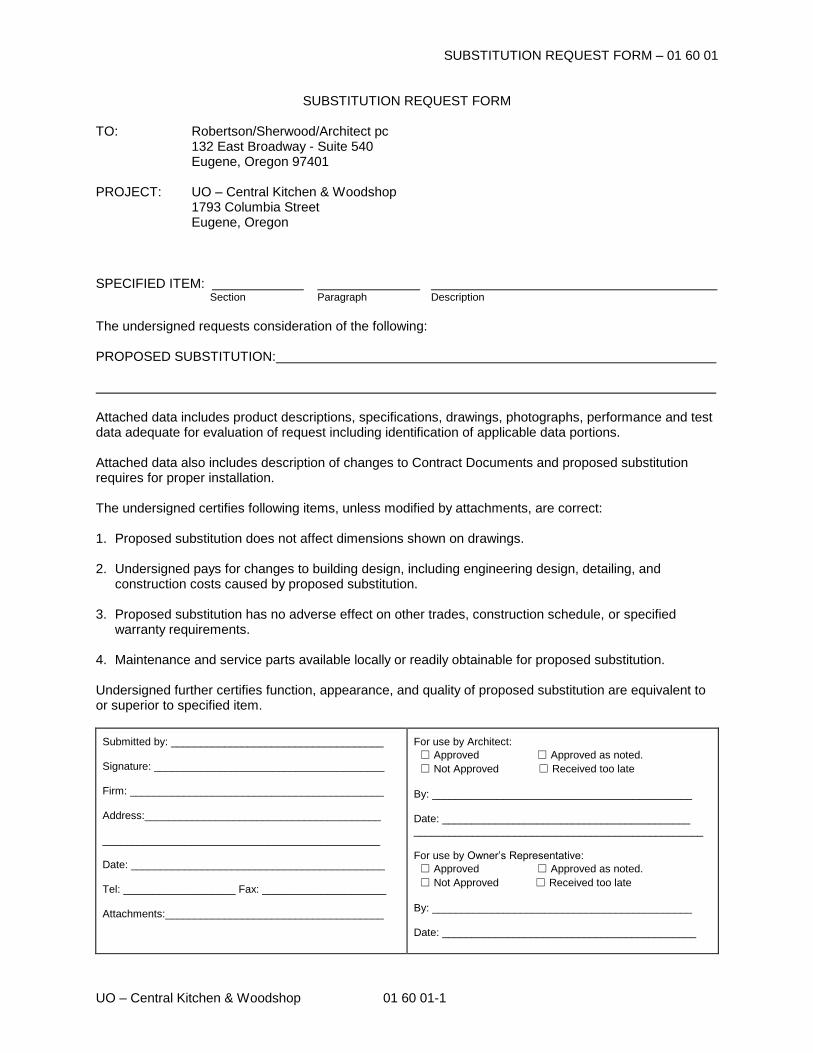
SUBSTITUTION REQUEST FORM – 01 60 01
UO – Central Kitchen & Woodshop 01 60 01-1
SUBSTITUTION REQUEST FORM TO: Robertson/Sherwood/Architect pc 132 East Broadway - Suite 540 Eugene, Oregon 97401 PROJECT: UO – Central Kitchen & Woodshop 1793 Columbia Street Eugene, Oregon
SPECIFIED ITEM: Section Paragraph Description The undersigned requests consideration of the following: PROPOSED SUBSTITUTION: Attached data includes product descriptions, specifications, drawings, photographs, performance and test data adequate for evaluation of request including identification of applicable data portions. Attached data also includes description of changes to Contract Documents and proposed substitution requires for proper installation. The undersigned certifies following items, unless modified by attachments, are correct: 1. Proposed substitution does not affect dimensions shown on drawings. 2. Undersigned pays for changes to building design, including engineering design, detailing, and
construction costs caused by proposed substitution. 3. Proposed substitution has no adverse effect on other trades, construction schedule, or specified
warranty requirements. 4. Maintenance and service parts available locally or readily obtainable for proposed substitution. Undersigned further certifies function, appearance, and quality of proposed substitution are equivalent to or superior to specified item.
Submitted by: ____________________________________ Signature: _______________________________________ Firm: ___________________________________________ Address:________________________________________ _______________________________________________ Date: ___________________________________________ Tel: ___________________ Fax: _____________________ Attachments:_____________________________________
For use by Architect:
☐ Approved ☐ Approved as noted.
☐ Not Approved ☐ Received too late
By: ____________________________________________ Date: __________________________________________ _________________________________________________ For use by Owner’s Representative:
☐ Approved ☐ Approved as noted.
☐ Not Approved ☐ Received too late
By: ____________________________________________ Date: ___________________________________________
EXECUTION AND CLOSEOUT REQUIREMENTS - 01 70 00
UO Housing - Central Kitchen & Woodshop 01 70 00 - 1
EXECUTION AND CLOSEOUT REQUIREMENTS
PART 1 GENERAL
1.01 SECTION INCLUDES
A. Examination, preparation, and general installation procedures.
B. Pre-installation meetings.
C. Cutting and patching.
D. Surveying for laying out the work.
E. Cleaning and protection.
F. Starting of systems and equipment.
G. Demonstration and instruction of Owner personnel.
H. General requirements for maintenance service.
1.02 RELATED REQUIREMENTS
A. Section 01 30 00 - Administrative Requirements: Submittals procedures.
B. Section 01 40 00 - Quality Requirements: Testing and inspection procedures.
C. Section 01 50 00 - Temporary Facilities and Controls: Temporary interior and exteriorenclosures.
D. Section 01 78 00 - Closeout Submittals: Project record documents, operation and maintenancedata, warranties and bonds.
1.03 SUBMITTALS
A. See Section 01 30 00 - Administrative Requirements, for submittal procedures.
B. Survey work: Submit name, address, and telephone number of Surveyor before starting surveywork.1. On request, submit documentation verifying accuracy of survey work.2. Submit a copy of site drawing signed by the Land Surveyor, that the elevations and locations
of the work are in conformance with Contract Documents.3. Submit surveys and survey logs for the project record.
C. Cutting and Patching: Submit written request in advance of cutting or alteration that affects:1. Structural integrity of any element of Project.2. Integrity of weather exposed or moisture resistant element.3. Efficiency, maintenance, or safety of any operational element.4. Visual qualities of sight exposed elements.5. Work of Owner or separate Contractor.
1.04 QUALIFICATIONS
A. For demolition work, employ a firm specializing in the type of work required.
B. For survey work, employ a land surveyor registered in Oregon and acceptable to Architect.Submit evidence of Surveyor's Errors and Omissions insurance coverage in the form of anInsurance Certificate.
1.05 PROJECT CONDITIONS
A. Grade site to drain. Maintain excavations free of water. Provide, operate, and maintain pumpingequipment.
B. Protect site from puddling or running water. Provide water barriers as required to protect site fromsoil erosion.
EXECUTION AND CLOSEOUT REQUIREMENTS - 01 70 00
UO Housing - Central Kitchen & Woodhsop 01 70 00 - 2
C. Ventilate enclosed areas to assist cure of materials, to dissipate humidity, and to preventaccumulation of dust, fumes, vapors, or gases.
D. Dust Control: Execute work by methods to minimize raising dust from construction operations.Provide positive means to prevent air-borne dust from dispersing into atmosphere and overadjacent property.
E. Erosion and Sediment Control: Plan and execute work by methods to control surface drainagefrom cuts and fills, from borrow and waste disposal areas. Prevent erosion and sedimentation.
F. Noise Control: Provide methods, means, and facilities to minimize noise produced byconstruction operations.
G. Pest and Rodent Control: Provide methods, means, and facilities to prevent pests and insectsfrom damaging the work.
H. Rodent Control: Provide methods, means, and facilities to prevent rodents from accessing orinvading premises.
I. Pollution Control: Provide methods, means, and facilities to prevent contamination of soil, water,and atmosphere from discharge of noxious, toxic substances, and pollutants produced byconstruction operations. Comply with federal, state, and local regulations.
1.06 COORDINATION
A. Coordinate scheduling, submittals, and work of the various sections of the Project Manual toensure efficient and orderly sequence of installation of interdependent construction elements, withprovisions for accommodating items installed later.
B. Notify affected utility companies and comply with their requirements.
C. Verify that utility requirements and characteristics of new operating equipment are compatible withbuilding utilities. Coordinate work of various sections having interdependent responsibilities forinstalling, connecting to, and placing in service, such equipment.
D. Coordinate space requirements, supports, and installation of mechanical and electrical work thatare indicated diagrammatically on Drawings. Follow routing shown for pipes, ducts, and conduit,as closely as practicable; place runs parallel with lines of building. Utilize spaces efficiently tomaximize accessibility for other installations, for maintenance, and for repairs.
E. In finished areas except as otherwise indicated, conceal pipes, ducts, and wiring within theconstruction. Coordinate locations of fixtures and outlets with finish elements.
F. Coordinate completion and clean-up of work of separate sections.
G. After Owner occupancy of premises, coordinate access to site for correction of defective work andwork not in accordance with Contract Documents, to minimize disruption of Owner's activities.
PART 2 PRODUCTS
2.01 PATCHING MATERIALS
A. New Materials: As specified in product sections; match existing products and work for patchingand extending work.
B. Type and Quality of Existing Products: Determine by inspecting and testing products wherenecessary, referring to existing work as a standard.
C. Product Substitution: For any proposed change in materials, submit request for substitutiondescribed in Section 01 60 00.
EXECUTION AND CLOSEOUT REQUIREMENTS - 01 70 00
UO Housing - Central Kitchen & Woodhsop 01 70 00 - 3
PART 3 EXECUTION
3.01 EXAMINATION
A. Verify that existing site conditions and substrate surfaces are acceptable for subsequent work.Start of work means acceptance of existing conditions.
B. Verify that existing substrate is capable of structural support or attachment of new work beingapplied or attached.
C. Examine and verify specific conditions described in individual specification sections.
D. Take field measurements before confirming product orders or beginning fabrication, to minimizewaste due to over-ordering or misfabrication.
E. Verify that utility services are available, of the correct characteristics, and in the correct locations.
F. Prior to Cutting: Examine existing conditions prior to commencing work, including elementssubject to damage or movement during cutting and patching. After uncovering existing work,assess conditions affecting performance of work. Beginning of cutting or patching meansacceptance of existing conditions.
3.02 PREPARATION
A. Clean substrate surfaces prior to applying next material or substance.
B. Seal cracks or openings of substrate prior to applying next material or substance.
C. Apply manufacturer required or recommended substrate primer, sealer, or conditioner prior toapplying any new material or substance in contact or bond.
3.03 PREINSTALLATION MEETINGS
A. When required in individual specification sections, convene a preinstallation meeting at the siteprior to commencing work of the section.
B. Require attendance of parties directly affecting, or affected by, work of the specific section.
C. Notify Architect four days in advance of meeting date.
D. Prepare agenda and preside at meeting:1. Review conditions of examination, preparation and installation procedures.2. Review coordination with related work.
E. Record minutes and distribute copies within two days after meeting to participants, with two copiesto Architect, Owner, participants, and those affected by decisions made.
3.04 LAYING OUT THE WORK
A. Verify locations of survey control points prior to starting work.
B. Promptly notify Architect of any discrepancies discovered.
C. Contractor shall locate and protect survey control and reference points.
D. Control datum for survey is that indicated on Drawings.
E. Protect survey control points prior to starting site work; preserve permanent reference pointsduring construction.
F. Promptly report to Architect the loss or destruction of any reference point or relocation requiredbecause of changes in grades or other reasons.
G. Replace dislocated survey control points based on original survey control. Make no changeswithout prior written notice to Architect.
H. Utilize recognized engineering survey practices.
EXECUTION AND CLOSEOUT REQUIREMENTS - 01 70 00
UO Housing - Central Kitchen & Woodhsop 01 70 00 - 4
I. Establish a minimum of two permanent bench marks on site, referenced to established controlpoints. Record locations, with horizontal and vertical data, on project record documents.
J. Establish elevations, lines and levels. Locate and lay out by instrumentation and similarappropriate means:1. Site improvements including pavements; stakes for grading, fill and topsoil placement; utility
locations, slopes, and invert elevations.2. Grid or axis for structures.3. Building foundation, column locations, ground floor elevations.
K. Periodically verify layouts by same means.
L. Maintain a complete and accurate log of control and survey work as it progresses.
M. On completion of foundation walls and major site improvements, prepare a certified surveyillustrating dimensions, locations, angles, and elevations of construction and site work.
3.05 GENERAL INSTALLATION REQUIREMENTS
A. Install products as specified in individual sections, in accordance with manufacturer's instructionsand recommendations, and so as to avoid waste due to necessity for replacement.
B. Make vertical elements plumb and horizontal elements level, unless otherwise indicated.
C. Install equipment and fittings plumb and level, neatly aligned with adjacent vertical and horizontallines, unless otherwise indicated.
D. Make consistent texture on surfaces, with seamless transitions, unless otherwise indicated.
E. Make neat transitions between different surfaces, maintaining texture and appearance.
3.06 CUTTING AND PATCHING
A. Whenever possible, execute the work by methods that avoid cutting or patching.
B. Perform whatever cutting and patching is necessary to:1. Complete the work.2. Fit products together to integrate with other work.3. Provide openings for penetration of mechanical, electrical, and other services.4. Match work that has been cut to adjacent work.5. Repair areas adjacent to cuts to required condition.6. Repair new work damaged by subsequent work.7. Remove samples of installed work for testing when requested.8. Remove and replace defective and non-conforming work.
C. Execute cutting and patching including excavation and fill to complete the work, to uncover workin order to install improperly sequenced work, to remove and replace defective or non-conformingwork, to remove samples of installed work for testing when requested, to provide openings in thework for penetration of mechanical and electrical work, to execute patching to complementadjacent work, and to fit products together to integrate with other work.
D. Execute work by methods that avoid damage to other work and that will provide appropriatesurfaces to receive patching and finishing.
E. Employ original installer to perform cutting for weather exposed and moisture resistant elements,and sight exposed surfaces.
F. Cut rigid materials using masonry saw or core drill. Pneumatic tools not allowed without priorapproval.
G. Restore work with new products in accordance with requirements of Contract Documents.
H. Fit work air tight to pipes, sleeves, ducts, conduit, and other penetrations through surfaces.
EXECUTION AND CLOSEOUT REQUIREMENTS - 01 70 00
UO Housing - Central Kitchen & Woodhsop 01 70 00 - 5
I. At penetrations of fire rated walls, partitions, ceiling, or floor construction, completely seal voidswith fire rated material in accordance with Section 07 84 00, to full thickness of the penetratedelement.
J. Patching:1. Finish patched surfaces to match finish that existed prior to patching. On continuous
surfaces, refinish to nearest intersection or natural break. For an assembly, refinish entireunit.
2. Match color, texture, and appearance.3. Repair patched surfaces that are damaged, lifted, discolored, or showing other imperfections
due to patching work. If defects are due to condition of substrate, repair substrate prior torepairing finish.
K. Refinish surfaces to match adjacent finish. For continuous surfaces, refinish to nearestintersection or natural break. For an assembly, refinish entire unit.
L. Make neat transitions. Patch work to match adjacent work in texture and appearance. Wherenew work abuts or aligns with existing, perform a smooth and even transition.
3.07 PROGRESS CLEANING
A. Maintain areas free of waste materials, debris, and rubbish. Maintain site in a clean and orderlycondition.
B. Remove debris and rubbish from pipe chases, plenums, attics, crawl spaces, and other closed orremote spaces, prior to enclosing the space.
C. Broom and vacuum clean interior areas prior to start of surface finishing, and continue cleaning toeliminate dust.
D. Collect and remove waste materials, debris, and trash/rubbish from site weekly and disposeoff-site; do not burn or bury.
3.08 PROTECTION OF INSTALLED WORK
A. Protect installed work from damage by construction operations.
B. Provide special protection where specified in individual specification sections.
C. Provide temporary and removable protection for installed products. Control activity in immediatework area to prevent damage.
D. Provide protective coverings at walls, projections, jambs, sills, and soffits of openings.
E. Protect finished floors, stairs, and other surfaces from traffic, dirt, wear, damage, or movement ofheavy objects, by protecting with durable sheet materials.
F. Prohibit traffic or storage upon waterproofed or roofed surfaces. If traffic or activity is necessary,obtain recommendations for protection from waterproofing or roofing material manufacturer.
G. Remove protective coverings when no longer needed; reuse or recycle plastic coverings ifpossible.
3.09 SYSTEM STARTUP
A. Coordinate schedule for start-up of various equipment and systems.
B. Verify that each piece of equipment or system has been checked for proper lubrication, driverotation, belt tension, control sequence, and for conditions that may cause damage.
C. Verify tests, meter readings, and specified electrical characteristics agree with those required bythe equipment or system manufacturer.
D. Verify that wiring and support components for equipment are complete and tested.
EXECUTION AND CLOSEOUT REQUIREMENTS - 01 70 00
UO Housing - Central Kitchen & Woodhsop 01 70 00 - 6
E. Execute start-up under supervision of applicable Contractor personnel and manufacturer'srepresentative in accordance with manufacturers' instructions.
F. Submit a written report that equipment or system has been properly installed and is functioningcorrectly.
3.10 DEMONSTRATION AND INSTRUCTION
A. Demonstrate start-up, operation, control, adjustment, trouble-shooting, servicing, maintenance,and shutdown of each item of equipment at scheduled time, at equipment location.
B. For equipment or systems requiring seasonal operation, perform demonstration for other seasonwithin six months.
C. Provide a qualified person who is knowledgeable about the Project to perform demonstration andinstruction of owner personnel.
3.11 ADJUSTING
A. Adjust operating products and equipment to ensure smooth and unhindered operation.
3.12 FINAL CLEANING
A. Use cleaning materials that are nonhazardous.
B. Clean interior and exterior glass, surfaces exposed to view; remove temporary labels, stains andforeign substances, polish transparent and glossy surfaces, vacuum carpeted and soft surfaces.
C. Remove all labels that are not permanent. Do not paint or otherwise cover fire test labels ornameplates on mechanical and electrical equipment.
D. Clean equipment and fixtures to a sanitary condition with cleaning materials appropriate to thesurface and material being cleaned.
E. Clean filters of operating equipment.
F. Clean debris from roofs, gutters, downspouts, and drainage systems.
G. Clean site; sweep paved areas, rake clean landscaped surfaces.
H. Remove waste, surplus materials, trash/rubbish, and construction facilities from the site; disposeof in legal manner; do not burn or bury.
3.13 CLOSEOUT PROCEDURES
A. Make submittals that are required by governing or other authorities.
B. Notify Architect when work is considered ready for Substantial Completion.
C. Submit written certification that Contract Documents have been reviewed, work has beeninspected, and that work is complete in accordance with Contract Documents and ready forArchitect's review.
D. Correct items of work listed in executed Certificates of Substantial Completion and comply withrequirements for access to Owner-occupied areas.
E. Notify Architect when work is considered finally complete.
F. Complete items of work determined by Architect's final inspection.
3.14 MAINTENANCE
A. Provide service and maintenance of components indicated in specification sections.
EXECUTION AND CLOSEOUT REQUIREMENTS - 01 70 00
UO Housing - Central Kitchen & Woodhsop 01 70 00 - 7
B. Maintenance service shall not be assigned or transferred to any agent or subcontractor withoutprior written consent of the Owner.
END OF SECTION
CONSTRUCTION WASTE MANAGEMENT AND DISPOSAL - 01 74 19
UO Housing - Central Kitchen & Woodshop 01 74 19 - 1
CONSTRUCTION WASTE MANAGEMENT AND DISPOSAL
PART 1 GENERAL
1.01 SECTION INCLUDES
A. Demolition and construction waste management and recycling goals.
B. Administrative and procedural requirements for the development and execution of a constructionwaste management plan.
1.02 CONSTRUCTION WASTE MANAGEMENT GOALS
A. The Owner has established that this Project shall generate the least amount of waste possibleand that processes that ensure the generation of as little waste as possible due to error, poorplanning, breakage, mishandling, contamination, or other factors shall be employed.
B. Of the inevitable waste that is generated, as many of the waste materials as economically feasibleshall be reused, salvaged, or recycled. Waste disposal in landfills shall be minimized.
C. Diversion Goal: A minimum 75% of total project waste shall be diverted from the landfill.
D. With regard to these goals the Contractor shall develop, for the Owner and Architect's review, aWaste Management Plan for this Project.
1.03 SUBMITTALS
A. See Section 01 30 00 - Administrative Requirements, for submittal procedures.
B. Submit a Construction Waste Management Plan.
C. Submit periodic and final summary report of waste materials recycled, salvaged and landfilled.
D. Submit weight tickets for all waste materials removed from the site during demolition andconstruction.
1.04 CONSTRUCTION WASTE MANAGEMENT PLAN
A. Draft Waste Management Plan: Prior to the Pre-Construction Conference, or prior to any wasteremoval, whichever occurs sooner, the Contractor shall meet with the Owner designatedrepresentative(s) and Architect to discuss preparation of a Draft Waste Management Plan. TheDraft Plan shall contain the following:1. Analysis of the proposed jobsite waste to be generated. Include the types of material to be
generated and estimated quantity of each material (in tons).2. Landfill options: Estimated cost of disposing of all project waste in transfer
station(s)/landfill(s), name of transfer station(s)/landfill(s) where Project waste would normallybe disposed of and tipping fees. Estimated cost of transportation and other relevant costsand fees.
3. Alternatives to Landfilling: A list of each material proposed to be salvaged or recycled duringthe course of the Project. The list of these materials is to include, at a minimum, the followingmaterials:a. Concreteb. Asphaltc. Bricksd. Concrete Masonry Units (CMU)e. Land Cleaning Debris - Land clearing debris shall not contribute to Diversion Goal
achievement.f. Clean dimensional woodg. Plywood, OSB, and particle boardh. Cardboardi. Paperj. Metalsk. Gypsum Wallboardl. Carpet
CONSTRUCTION WASTE MANAGEMENT AND DISPOSAL - 01 74 19
UO Housing - Central Kitchen & Woodhsop 01 74 19 - 2
m. Paintn. Plastico. Glassp. Rigid foam insulationq. Beverage Containers
4. Material Handling Procedures: A description of the means by which any waste materialsidentified in item (3) above will be protected from contamination, and a description of themeans to be employed in recycling the above materials consistent with requirements foracceptance by designated facilities.a. The facility diversion rate shall be required for facilities hauling and processing
commingled waste in accordance with the LEED-NC v.2.2 Credit Interpretation Request(CIR) Ruling dated 12/02/2005. Identifying the facility diversion rate by means of visualinspection is not acceptable per CIR Ruling dated 1/29/2009.
b. Reference: http://www.usgbc.org/LEED/Credit/CIRDetails.aspx?RequirementID=6755. Transportation: A description of the means of transportation of the recyclable materials
(whether materials will be site-separated and self-hauled to designated centers, or whethermixed materials will be collected by a waste hauler and removed from the site) anddestination of materials. The final destination must be approved by Owner designatedrepresentative(s).
6. Source Reduction: List processes that minimize waste such as working with suppliers totake back or buy back substandard, rejected or unused items and to deliver supplies usingreturnable pallets and containers. Also include procedures to minimize breakage,mishandling, contamination, and other factors that reduce job site waste.
7. Meetings: A description of the regular meetings to be held to address waste management.Contractor shall conduct Construction Waste Management meetings. Meetings shall includesubcontractors affected by the Waste Management Plan as well as Owner designatedrepresentative(s). At a minimum, waste management goals and issues shall be discussed atthe following meetings:a. Pre-bid meeting.b. Pre-construction meeting.c. Regularly scheduled job-site meetings.
8. Indicate any instance where compliance with requirements of this specification does notappear to be possible and request resolution from the Owner and Architect.
B. Waste Management Plan Review Meeting: Once the Owner and Architect have reviewed theDraft Waste Management Plan and prior to any waste removal at the site, schedule and conduct afollow-up meeting. The purpose of the meeting is to review the Draft Waste Management Planand discuss procedures, schedules and specific requirements for waste materials recycling anddisposal. Discuss coordination and interface between the Contractor and other constructionactivities. Identify and resolve potential compliance problems with requirements. Record minutesof the meeting, identifying all conclusions reached and matters requiring further resolution.1. Attendees: The Contractor and related Contractor personnel associated with the work of this
section, including personnel to be in charge of the waste management program, Architect,Owner and such additional personnel as the Architect or Owner deem appropriate.
C. Final Construction Waste Management Plan: Make any revisions to the Draft Waste ManagementPlan agreed upon during the review meeting and incorporate resolutions agreed to be madesubsequent to the meeting. Submit the revised plan to the Owner and Architect for approvalwithin 10 calendar days of the meeting.
PART 2 PRODUCTS (NOT USED)
PART 3 EXECUTION
3.01 IMPLEMENTATION OF CONSTRUCTION WASTE MANAGEMENT PLAN
A. Manager: The Contractor shall designate an on-site party (or parties) responsible for instructingworkers and overseeing and documenting results of the Waste Management Plan for the Project.
B. Distribution: The Contractor shall distribute copies of the Waste Management Plan to the Job SiteForeman, each Subcontractor, the Owner, and the Architect.
CONSTRUCTION WASTE MANAGEMENT AND DISPOSAL - 01 74 19
UO Housing - Central Kitchen & Woodhsop 01 74 19 - 3
C. Instruction: The Contractor shall provide on-site instruction of appropriate separation, handling,and recycling, salvage, reuse, and return methods to be used by all parties at the appropriatestages of the Project.
D. Separation facilities: The Contractor shall lie out and label a specific area to facilitate separationof materials for potential recycling, salvage, reuse, and return. Recycling and waste bin areas areto be kept neat and clean and clearly marked in order to avoid contamination of materials.
E. Hazardous Waste: Hazardous wastes shall be separated, stored, and disposed of according tolocal regulations.
F. Application for Progress Payments: The Contractor shall submit with each Application forProgress Payment a Summary of Waste Generated by the Project. Failure to submit thisinformation shall render the Application for Payment incomplete and shall delay ProgressPayment. The Summary shall be submitted on a form acceptable to the Owner and shall containthe following information:1. The amount of waste (in tons) landfilled from the Project, the identity of the transfer
station/landfill, the total amount of tipping fees paid at the landfill, the transportation cost, andthe total disposal cost. Include manifests, weight tickets, receipts, and invoices.
2. For each material recycled, reused, or salvaged from the Project, the amount (in tons), thedate removed from the jobsite, the receiving party, the transportation cost, the amount of anymoney paid or received for the recycled or salvaged material, and the net total cost orsavings of salvage or recycling each material. Attach manifests, weight tickets, receipts, andinvoices.
G. Closeout: At the end of the project the Contractor shall submit a Final Waste ManagementReport. The Report shall be submitted on a form acceptable to the Owner and shall contain thefollowing information:1. The total amount of waste landfilled from the Project, the identity of the transfer
station/landfill, the total amount of tipping fees paid at the landfill, the transportation cost, andthe total disposal cost.
2. The total amount (in tons) of each material recycled, reused, or salvaged from the Project,the receiving party, and net cost savings or additional costs resulting from separating andrecycling (versus landfilling) each material. The total amount of all materials recycled in tonsand the total net cost savings or additional costs.
3. The total percentage of material recycled in tons.
END OF SECTION
CLOSEOUT SUBMITTALS - 01 78 00
UO Housing - Central Kitchen & Woodshop 01 78 00 - 1
CLOSEOUT SUBMITTALS
PART 1 GENERAL
1.01 SECTION INCLUDES
A. Project Record Documents.
B. Operation and Maintenance Data.
C. Warranties and bonds.
1.02 RELATED REQUIREMENTS
A. Section 00 72 00 - General Conditions: Performance bond and labor and material paymentbonds, warranty, and correction of work.
B. Section 01 30 00 - Administrative Requirements: Submittals procedures, shop drawings, productdata, and samples.
C. Section 01 70 00 - Execution and Closeout Requirements: Contract closeout procedures.
D. Individual Product Sections: Specific requirements for operation and maintenance data.
E. Individual Product Sections: Warranties required for specific products or Work.
1.03 SUBMITTALS
A. Project Record Documents: Submit documents to Architect with claim for final Application forPayment.
B. Operation and Maintenance Data:1. Submit two copies of preliminary draft or proposed formats and outlines of contents before
start of Work. Architect will review draft and return one copy with comments.2. For equipment, or component parts of equipment put into service during construction and
operated by Owner, submit completed documents within ten days after acceptance.3. Submit one copy of completed documents 15 days prior to final inspection. This copy will be
reviewed and returned after final inspection, with Architect comments. Revise content of alldocument sets as required prior to final submission.
4. Submit two sets of revised final documents in final form within 10 days after final inspection.
C. Warranties and Bonds:1. For equipment or component parts of equipment put into service during construction with
Owner's permission, submit documents within 10 days after acceptance.2. Make other submittals within 10 days after Date of Substantial Completion, prior to final
Application for Payment.3. For items of Work for which acceptance is delayed beyond Date of Substantial Completion,
submit within 10 days after acceptance, listing the date of acceptance as the beginning of thewarranty period.
PART 2 PRODUCTS - NOT USED
PART 3 EXECUTION
3.01 PROJECT RECORD DOCUMENTS
A. Maintain on site one set of the following record documents; record actual revisions to the Work:1. Drawings.2. Specifications.3. Addenda.4. Change Orders and other modifications to the Contract.5. Reviewed shop drawings, product data, and samples.6. Manufacturer's instruction for assembly, installation, and adjusting.
B. Ensure entries are complete and accurate, enabling future reference by Owner.
CLOSEOUT SUBMITTALS - 01 78 00
UO Housing - Central Kitchen & Woodhsop 01 78 00 - 2
C. Store record documents separate from documents used for construction.
D. Record information concurrent with construction progress.
E. Specifications: Legibly mark and record at each product section description of actual productsinstalled, including the following:1. Manufacturer's name and product model and number.2. Product substitutions or alternates utilized.3. Changes made by Addenda and modifications.
F. Record Drawings and Shop Drawings: Legibly mark each item to record actual constructionincluding:1. Measured depths of foundations in relation to finish first floor datum.2. Measured horizontal and vertical locations of underground utilities and appurtenances,
referenced to permanent surface improvements.3. Measured locations of internal utilities and appurtenances concealed in construction,
referenced to visible and accessible features of the Work.4. Field changes of dimension and detail.5. Details not on original Contract drawings.
3.02 OPERATION AND MAINTENANCE DATA
A. Source Data: For each product or system, list names, addresses and telephone numbers ofSubcontractors and suppliers, including local source of supplies and replacement parts.
B. Product Data: Mark each sheet to clearly identify specific products and component parts, anddata applicable to installation. Delete inapplicable information.
C. Drawings: Supplement product data to illustrate relations of component parts of equipment andsystems, to show control and flow diagrams. Do not use Project Record Documents asmaintenance drawings.
D. Typed Text: As required to supplement product data. Provide logical sequence of instructions foreach procedure, incorporating manufacturer's instructions.
3.03 OPERATION AND MAINTENANCE DATA FOR MATERIALS AND FINISHES
A. For Each Product, Applied Material, and Finish:1. Product data, with catalog number, size, composition, and color and texture designations.2. Information for re-ordering custom manufactured products.
B. Instructions for Care and Maintenance: Manufacturer's recommendations for cleaning agents andmethods, precautions against detrimental cleaning agents and methods, and recommendedschedule for cleaning and maintenance.
C. Moisture protection and weather-exposed products: Include product data listing applicablereference standards, chemical composition, and details of installation. Provide recommendationsfor inspections, maintenance, and repair.
D. Additional information as specified in individual product specification sections.
E. Where additional instructions are required, beyond the manufacturer's standard printedinstructions, have instructions prepared by personnel experienced in the operation andmaintenance of the specific products.
F. Provide a listing in Table of Contents for design data, with tabbed fly sheet and space for insertionof data.
3.04 OPERATION AND MAINTENANCE DATA FOR EQUIPMENT AND SYSTEMS
A. For Each Item of Equipment and Each System:1. Description of unit or system, and component parts.2. Identify function, normal operating characteristics, and limiting conditions.3. Include performance curves, with engineering data and tests.
CLOSEOUT SUBMITTALS - 01 78 00
UO Housing - Central Kitchen & Woodhsop 01 78 00 - 3
4. Complete nomenclature and model number of replaceable parts.
B. Where additional instructions are required, beyond the manufacturer's standard printedinstructions, have instructions prepared by personnel experienced in the operation andmaintenance of the specific products.
C. Panelboard Circuit Directories: Provide electrical service characteristics, controls, andcommunications; typed.
D. Include color coded wiring diagrams as installed.
E. Operating Procedures: Include start-up, break-in, and routine normal operating instructions andsequences. Include regulation, control, stopping, shut-down, and emergency instructions.Include summer, winter, and any special operating instructions.
F. Maintenance Requirements: Include routine procedures and guide for preventative maintenanceand trouble shooting; disassembly, repair, and reassembly instructions; and alignment, adjusting,balancing, and checking instructions.
G. Provide servicing and lubrication schedule, and list of lubricants required.
H. Include manufacturer's printed operation and maintenance instructions.
I. Include sequence of operation by controls manufacturer.
J. Provide original manufacturer's parts list, illustrations, assembly drawings, and diagrams requiredfor maintenance.
K. Provide control diagrams by controls manufacturer as installed.
L. Provide Contractor's coordination drawings, with color coded piping diagrams as installed.
M. Provide charts of valve tag numbers, with location and function of each valve, keyed to flow andcontrol diagrams.
N. Provide list of original manufacturer's spare parts, current prices, and recommended quantities tobe maintained in storage.
O. Include test and balancing reports.
P. Additional Requirements: As specified in individual product specification sections.
3.05 ASSEMBLY OF OPERATION AND MAINTENANCE MANUALS
A. Assemble operation and maintenance data into durable manuals for Owner's personnel use, withdata arranged in the same sequence as, and identified by, the specification sections.
B. Where systems involve more than one specification section, provide separate tabbed divider foreach system.
C. Prepare instructions and data by personnel experienced in maintenance and operation ofdescribed products.
D. Prepare data in the form of an instructional manual.
E. Binders: Commercial quality, 8-1/2 by 11 inch three D side ring binders with durable plasticcovers; 2 inch maximum ring size. When multiple binders are used, correlate data into relatedconsistent groupings.
F. Cover: Identify each binder with typed or printed title OPERATION AND MAINTENANCEINSTRUCTIONS; identify title of Project; identify subject matter of contents.
G. Project Directory: Title and address of Project; names, addresses, and telephone numbers ofArchitect, Consultants, Contractor and subcontractors, with names of responsible parties.
CLOSEOUT SUBMITTALS - 01 78 00
UO Housing - Central Kitchen & Woodhsop 01 78 00 - 4
H. Tables of Contents: List every item separated by a divider, using the same identification as on thedivider tab; where multiple volumes are required, include all volumes Tables of Contents in eachvolume, with the current volume clearly identified.
I. Dividers: Provide tabbed dividers for each separate product and system; identify the contents onthe divider tab; immediately following the divider tab include a description of product and majorcomponent parts of equipment.
J. Text: Manufacturer's printed data, or typewritten data on 24 pound paper.
K. Drawings: Provide with reinforced punched binder tab. Bind in with text; fold larger drawings tosize of text pages.
L. Arrange content by systems under section numbers and sequence of Table of Contents of thisProject Manual.
M. Contents: Prepare a Table of Contents for each volume, with each product or system descriptionidentified, in three parts as follows:1. Part 1: Directory, listing names, addresses, and telephone numbers of Architect, Contractor,
Subcontractors, and major equipment suppliers.2. Part 2: Operation and maintenance instructions, arranged by system and subdivided by
specification section. For each category, identify names, addresses, and telephone numbersof Subcontractors and suppliers. Identify the following:a. Significant design criteria.b. List of equipment.c. Parts list for each component.d. Operating instructions.e. Maintenance instructions for equipment and systems.f. Maintenance instructions for special finishes, including recommended cleaning methods
and materials, and special precautions identifying detrimental agents.3. Part 3: Project documents and certificates, including the following:
a. Shop drawings and product data.b. Air and water balance reports.c. Certificates.d. Photocopies of warranties and bonds.
N. Provide a listing in Table of Contents for design data, with tabbed dividers and space for insertionof data.
O. Table of Contents: Provide title of Project; names, addresses, and telephone numbers ofArchitect, Consultants, and Contractor with name of responsible parties; schedule of products andsystems, indexed to content of the volume.
3.06 WARRANTIES AND BONDS
A. Obtain warranties and bonds, executed in duplicate by responsible Subcontractors, suppliers, andmanufacturers, within 10 days after completion of the applicable item of work. Except for itemsput into use with Owner's permission, leave date of beginning of time of warranty until the Date ofSubstantial completion is determined.
B. Verify that documents are in proper form, contain full information, and are notarized.
C. Co-execute submittals when required.
D. Retain warranties and bonds until time specified for submittal.
E. Manual: Bind in commercial quality 8-1/2 by 11 inch three D side ring binders with durable plasticcovers.
F. Cover: Identify each binder with typed or printed title WARRANTIES AND BONDS, with title ofProject; name, address and telephone number of Contractor and equipment supplier; and nameof responsible company principal.
CLOSEOUT SUBMITTALS - 01 78 00
UO Housing - Central Kitchen & Woodhsop 01 78 00 - 5
G. Table of Contents: Neatly typed, in the sequence of the Table of Contents of the Project Manual,with each item identified with the number and title of the specification section in which specified,and the name of product or work item.
H. Separate each warranty or bond with index tab sheets keyed to the Table of Contents listing.Provide full information, using separate typed sheets as necessary. List Subcontractor, supplier,and manufacturer, with name, address, and telephone number of responsible principal.
END OF SECTION
LEED REQUIREMENTS - 01 81 13
UO Housing - Central Kitchen & Woodshop 01 81 13 - 1
LEED REQUIREMENTS
PART 1 - GENERAL
1.01 SECTION INCLUDES
A. General requirements and procedures for compliance with certain U.S. Green Building Council(USGBC) LEED® prerequisites and credits needed for the Project to obtain LEED Goldcertification.
B. Other LEED prerequisites and credits needed to obtain LEED certification are dependent onmaterial selections and may not be specifically identified as LEED requirements. Compliance withrequirements needed to obtain LEED prerequisites and credits may be used as one criterion toevaluate substitution requests.
C. Additional LEED prerequisites and credits needed to obtain the indicated LEED certification aredependent on the Architect's design and other aspects of the Project that are not part of the Workof this contract.
1.02 RELATED REQUIREMENTS
A. It should be assumed that all sections may include requirements intended to achieve LEEDcredits.
B. Section 01 74 19 - Construction Waste Management and Disposal
C. Section 01 81 19 - Construction Indoor Air Quality.
D. Divisions 02 through 48 Section for LEED Requirements specific to the Work of each of theseSections. These requirements may or may not include reference to LEED.
E. Section 01 91 13 - General Commissioning Requirements
1.03 DEFINITIONS
A. LEED-NC 2009: Leadership in Energy and Environmental Design - Green Building Rating Systemfor New Construction and Major Renovations version 2009. LEED is a national rating system forgreen buildings created by the US Green Building Council and administered by the Green BuildingCertification Institute. All references to LEED throughout the Construction Documents shall meanLEED-NC.
B. Reused Material: Salvaged, refurbished or reused materials, products and furnishings that havebeen returned to active use in the same or related capacity as their original use.
C. Recycled Content: The percentage by weight of constituents that have been recovered orotherwise diverted from the solid waste stream, either during the manufacturing process(pre-consumer or post-industrial), or after consumer use (post-consumer) as defined by ISO14021.1. Scraps, spills or other waste from the original manufacturing process that are combined with
other constituents after a minimal amount of reprocessing for use in the further production ofthe same product are not recycled materials.
2. Discarded materials from one manufacturing process that are used as constituents inanother manufacturing process are pre-consumer recycled materials.
D. Regional Materials: Materials that are harvested (extracted or recovered), processed andmanufactured within a radius of 500 miles from the Project location.
E. Rapidly Renewable Materials: Materials considered to be agricultural products, both fiber andanimal, that take 10 years or less to grow or raise, and to harvest in an ongoing and sustainablefashion. Rapidly renewable materials include products made from straw, jute, flax, bamboo,cotton, vegetable oil, wool or sunflower seed hulls.
F. Chain-of-Custody Certificate: A certificate signed by a manufacturer certifying a wood product wasobtained from forests certified by a Forest Stewardship Council (FSC) accredited certification
LEED REQUIREMENTS - 01 81 13
UO Housing - Central Kitchen & Woodhsop 01 81 13 - 2
body to comply with FSC 1.2, “Principals and Criteria.” Certificates shall include evidence that themill and distributor are certified for chain-of-custody by a FSC-accredited certification body.
G. Composite Wood and Agrifiber Board: Manufactured materials made from wood or agriculturalfibers manufactured with bonding agents. Composite wood materials include particle board,medium density fiberboard (MDF), plywood, strawboard, wheatboard, panel substrates and doorcores.
1.04 SUBMITTALS
A. See Section 01 30 00 - Administrative Requirements, for submittal procedures.
B. General: Submit additional LEED related submittals included in other Sections of theSpecifications.
C. LEED submittals are in addition to other submittals. If submitted item is identical to that submittedto comply with other requirements, submit duplicate copies as a separate submittal to verifycompliance with indicated LEED requirements.
D. Project Construction Materials Cost Data: Provide the necessary material cost data required tocomplete the LEED-Online calculators, including the total Project materials cost and itemizedcosts of specific materials being tracked for LEED Materials and Resources credits. The totalproject construction materials cost includes all materials contained in CSI MasterFormat™ 2004Edition Divisions 03 through 10 and 32 (Sections 32 10 00 - Paving, 32 30 00 - SiteImprovements, and 32 90 00 - Planting). All material costs exclude labor and equipment. Thetotal materials cost is exclusive of Specialties, Conveying Systems and Mechanical and Electricalcomponents.
E. LEED Action Plans: Within 30 days of Notice to Proceed submit the following action plans:1. Credit MRc2 - Construction Waste Management: Construction waste management plan
complying with Section 01 74 19 - Construction Waste Management and Disposal.2. Credit EQc3.1 - Construction IAQ Management Plan: Construction indoor air quality
management plan complying with Section 01 81 19 - Construction Indoor Air Quality.
F. LEED Progress Reports: Concurrent with each Application for Payment, submit reportssummarizing progress in construction and purchasing activities related to the following credits:1. Credit MRc2 - Construction Waste Management: Construction waste reduction progress
reports complying with Section 01 74 19 - Construction Waste Management and Disposal.2. Credit MRc4 - Recycled Content: Summary of product data and material costs collected for
all recycled content materials that have been purchased or installed.3. Credit MRc5 - Regional Materials: Summary of manufacturer's information and material
costs collected for all regional materials that have been purchased or installed.4. Credit MRc7 - Certified Wood: Summary of product data and material costs collected for all
FSC-certified wood products that have been purchased or installed.5. Credit EQc3 - Construction IAQ Management Plan: Construction indoor air quality
management reports complying with Section 01 81 19 - Construction Indoor Air Quality.6. Credit EQc4 - Low-Emitting Materials: Summary of product data collected for all adhesives,
sealants, paints, coatings, flooring, composite wood materials and laminating adhesives usedto fabricate composite wood assemblies that are installed inside of the building's moisturebarrier.
G. LEED Documentation Submittals: For each Section of the Specification, submit the following foreach applicable LEED Credit.1. Pre-requisite SSp1 - Construction Activity Pollution Prevention:
a. Graphical erosion and sedimentation control site planb. Written specifications or executive summary that outlines the specific implemented
measures and best practices employed on site.c. Corroborating progress records such as time/date stamped digital photographs,
inspection logs or formal reports.d. Credit SSc7.2 - Heat Island Effect, Roof: Cut sheets and product data for roofing
materials indicating reflectance and emittance, or solar reflectance index. Reflectancemust be measured according to ASTM E903-96, ASTM E1918-97, or ASTM C1549-04.
LEED REQUIREMENTS - 01 81 13
UO Housing - Central Kitchen & Woodhsop 01 81 13 - 3
Emittance must be measured according to ASTM E408-71 or ASTM C1371-04. SRImust be calculated according to ASTM E1980-01).
e. Credit SSc8 - Light Pollution Reduction: Cut sheets for all exterior light fixtures indicatinglamp lumen data and shielding and cut-off information.
f. Credit MRc2 - Construction Waste Management:1) Complete LEED Submittal Template.2) Comply with Section 01 74 19 - Construction Waste Management and Disposal.3) Construction waste management plan.4) Itemized waste hauling certificates/receipts for all waste removed from the Project
site and documentation of recycling recovery rate for off-site sorting facilities (ifwaste is commingled).
g. Credit MRc4 - Recycled Content:1) Complete LEED Submittal Template.2) Cut sheet, product literature or letter from manufacturer that clearly indicates the
percentage by weight of post-consumer and pre-consumer (post-industrial)recycled content.
3) Material cost.h. Credit MRc5 - Regional Materials:
1) Complete LEED Submittal Template.2) Cut sheet, product literature or letter from manufacturer indicating the location of
harvest, processing and manufacturer.3) Material cost.
i. Credit MRc7 - Certified Wood:1) Complete LEED Submittal Template.2) Copies of vendor invoices for each certified wood product.3) FSC chain-of-custody certificates for each certified wood product with
chain-of-custody number indicated.4) Material cost.
j. Credit IEQc3.1 - Construction IAQ Management Plan, During Construction:1) Complete LEED Submittal Template.2) Comply with Section 01 81 19 - Construction Indoor Air Quality.3) Cut sheets indicating MERV values for filtration media used during construction.4) Time/Date stamped digital photographs highlighting the IAQ Management Plan
practices, labeled to identify the highlighted approach. At least 18 photographs -six photographs taken on three different occasions during construction.
k. Credit IEQc3.2 - Construction IAQ Management Plan, After Construction:1) Narrative outlining the building flush-out procedures, including start and finish dates
and mechanical system settings. If possible, providing trend log from DDC systemfor flush-out period.
2) If IAQ testing is performed in place of building flush-out, provide specifications anddocumentation demonstrating conformance with IAQ testing procedures per creditrequirements.
l. Credit IEQc4.1 - Low-Emitting Materials, Adhesives and Sealants:1) Complete LEED Submittal Template.2) Product data and Material Safety Data Sheets (MSDS) for all adhesives and
sealants used inside the building's moisture barrier indicating the Volatile OrganicCompound (VOC) content of each product and verifying that each product meetsthe LEED requirements (Refer to “Low Emitting Materials” paragraph in Part 2).Indicate VOC content in grams/liter (g/l).
3) List of all installed adhesives and sealants including manufacturer, quantity used ingallons and VOC content.
m. Credit IEQc4.2 - Low-Emitting Materials, Paints and Coatings:1) Complete LEED Submittal Template.2) Product data and Material Safety Data Sheets (MSDS) for all paints and coatings
used inside the building's moisture barrier indicating the VOC content of eachproduct and verifying that each product meets the LEED requirements (Refer to“Low Emitting Materials” paragraph in Part 2). Indicate VOC content in grams/liter(g/l).
LEED REQUIREMENTS - 01 81 13
UO Housing - Central Kitchen & Woodhsop 01 81 13 - 4
3) List of all installed paints including manufacturer, quantity used in gallons and VOCcontent.
n. Credit IEQc4.3 - Low-Emitting Materials, Flooring Systems:1) Complete LEED Submittal Template.2) Cut sheets or letter from manufacturer clearly indicating that all carpet products
meet the CRI Green Label Plus Test Program requirements.3) Cut sheets or letter from manufacturer clearly indicating that all carpet cushion
products meet the CRI Green Label Test Program requirements.4) Product data and Material Safety Data Sheets (MSDS) for all carpet adhesives
indicating the Volatile Organic Compound (VOC) content of each product andverifying that each product meets the LEED requirements (Refer to “Low EmittingMaterials” paragraph in Part 2 for IEQc4.1). Indicate VOC content in grams/liter(g/l).
5) Cut sheets or letter from manufacturer clearly indicating that all hard surface andresilient flooring is certified compliant with the FloorScore standard or equivalent.
6) Product data and Material Safety Data Sheets (MSDS) for all sealers, stains andfinishes applied on-site to concrete, wood, bamboo and cork flooring indicating theVolatile Organic Compound (VOC) content of each product and verifying that eachproduct meets the LEED requirements (Refer to “Low Emitting Materials”paragraph in Part 2 for IEQc4.2). Indicate VOC content in grams/liter (g/l).
7) Product data and Material Safety Data Sheets (MSDS) for all tile setting adhesivesand grouts indicating the Volatile Organic Compound (VOC) content of eachproduct and verifying that each product meets the LEED requirements (Refer to“Low Emitting Materials” paragraph in Part 2 for IEQc4.1). Indicate VOC content ingrams/liter (g/l).
o. Credit IEQc4.4 - Low-Emitting Materials, Composite Wood:1) Complete LEED Submittal Template.2) Cut sheets clearly indicating the bonding agents used for each composite wood
and agrifiber product and assembly, as well as all laminating adhesives used onand off-site, demonstrating that no added urea-formaldehyde resins are used inthese products.
p. Credit ID2 - Mercury Reduction1) Complete LEED Submittals Template.2) Cut sheets for all fluorescent lamps used on project, indicating mercury content
and service life.
PART 2 - PRODUCTS
2.01 SUMMARY OF REFERENCED STANDARDS
A. Credit SSc7.2 - Heat Island Effect, Roof1. Solar Reflectance Index (SRI) must meet the following:
Roof Type Slope SRI
Low-Sloped Roof less than 2:12 78Steep-Sloped Roof more than 2:12 29
B. Credit MRc4 - Recycled Content:1. This product must contain a minimum post-consumer and post-industrial recycled content.
C. Credit MRc5 - Regional Materials:1. This product must be sourced by a manufacturer or supplier that harvests, extracts,
processes and manufactures the product within 500 miles of the project site.
D. Credit MRc7 - Certified Wood:1. This product must contain Forest Stewardship Council Pure Certified wood.2. Forest Stewardship Council website: http://www.fsc.org/
E. Credit IEQc4.1: Adhesives and Sealants
LEED REQUIREMENTS - 01 81 13
UO Housing - Central Kitchen & Woodhsop 01 81 13 - 5
1. Adhesives and sealants used on the interior of the building during construction shall complywith the VOC limits of the South Coast Rule #1168 by the South Coast Air QualityManagement District, dated July 1, 2005 and rule amendment date of January 7, 2005(www.aqmd.gov/rules/reg/reg11/r1168.pdf<http://www.aqmd.gov/rules/reg/reg11/r1168.pdf>). VOC limits in grams per liter foradhesives and sealants used on interior of building are as follows:
Welding and Installation VOC Limit (g/L)
Indoor Carpet Adhesives 50Carpet Pad Adhesives 50Wood Flooring Adhesives 100Rubber Flooring Adhesives 60Subfloor Adhesives 50Ceramic Tile Adhesives 65VCT and Asphalt Tile Adhesives 50Dry Wall and Panel Adhesives 50Cove Base Adhesives 50Multipurpose Construction Adhesives 70Structural Glazing Adhesives 100PVC Welding 510CPVC Welding 490ABS Welding 325Plastic Cement Welding 250Adhesive Primer for Plastic 550Contact Adhesives 80Special Purpose Contact Adhesives 250Structural Wood Member Adhesives 140Sheet Applied Rubber Lining Operations 850Top and Trim Adhesives 250
2. VOC limits in grams per liter for adhesives and sealants used on interior of building are asfollows:
Substrates VOC Limit (g/L)
Metal to Metal 30Plastic Foams 50Porous Material Except Wood 50Wood 30Fiberglass 80
SealantsArchitectural 250Other 250
Sealant PrimersArchitectural - Nonporous 250Architectural - Porous 775Other 750
3. Aerosol adhesives used on the interior of the building shall comply with the VOC limits ofGreen Seal Standard for Commercial Adhesives GS-36 requirements in effect on October19, 2000. VOC limits in percent by weight for aerosol adhesives used on interior of buildingare as follows.
Aerosol Adhesives VOC Limit (g/L)
LEED REQUIREMENTS - 01 81 13
UO Housing - Central Kitchen & Woodhsop 01 81 13 - 6
General Purpose Spray Mist 65% VOCs by weightGeneral Purpose Web Stray 55% by weightSpecial Purpose Aerosol Adhesive 70% by weight
4. Limits on VOCs in grams per liter for carpet adhesives shall comply with the VOC limitsshown below:
Adhesives VOC Limit (g/L)
Total VOCs 50
F. Credit IEQc4.2: Paints and Coatings1. Paints applied on the interior of the building shall comply with Green Seal Product Specific
Environmental Requirements (www.greenseal.org/standard/paints.htm). The Green Sealstandard is intended for paints and anti-corrosive paints. Both interior and exterior paints areaddressed by the standard, but only limits for interior paints apply to a LEED project.Architectural paints coating and primers applied to interior walls as well as Anti-corrosivepaints applied to interior ferrous metal shall not exceed the VOC limits set forth in Green SealStandard GS-11 and GS-03, respectively. Limits on VOCs in grams per liter for paints andanti-corrosive paints are as follows:
Interior Paint Coatings VOC Limit (g/L minus water)
Flat Coating or Flat Primer (GS-11-93) 50Non-Flat Coating or Non-Flat Primer(GS-11-93)
50
Anti-Corrosive/Anti-Rust Paint (GS-03-97) 100
2. Clear wood finishes, floor coatings, stain, sealers and shellac applied to interior elementsduring construction shall comply with the VOC limits set forth in South coast Air QualityManagement District (SCAQMD) Rule 1113, Architectural Coatings, dated January, 2004.
Other Interior Coatings VOC Limit (g/L minus water)
Sealers and Undercoater 100Concrete Curing Components 100Waterproofing Sealers 100Waterproofing Concrete / Masonry Sealers 100Floor Coatings 50Japan/Faux Finishing Coatings 350Magnesite Cement Coatings 450Stains 100Clear Wood Finish: Lacquer 275Clear Wood Finish: Sanding Sealer 275Clear Wood Finish: Varnish 275Clear Brushing Lacquer 275Pigmented Lacquer 275Shellac: Clear 730Shellac: Pigmented 550Wood Preservatives 350Low-Solids Coatings 120
G. Credit IEQc4.3: Flooring Systems:1. Carpets installed within the building during construction shall meet the testing and product
requirements of the Carpet and Rug Institute Green Label Plus program.
LEED REQUIREMENTS - 01 81 13
UO Housing - Central Kitchen & Woodhsop 01 81 13 - 7
2. Carpet cushion installed within the building during construction shall meet thee requirementsof the Carpet and Rug Institute Green Label program.
3. Carpet adhesives shall meet the requirements of IEQc4.1: VOC limit of 50 g/l.4. Hard surface and resilient flooring installed within the building must be certified as compliant
with the FloorScore (or equivalent) standard by an independent third-party. Flooring productscovered by FloorScore include vinyl, linoleum, laminate flooring, wood flooring, rubberflooring and wall base.
5. Finishes, such as sealers and stains, applied to concrete, wood, bamboo and cork flooringshall comply with the VOC limits set forth in South coast Air Quality Management District(SCAQMD) Rule 1113, Architectural Coatings, dated January, 2004.
6. Tile setting adhesives and grout shall comply with the VOC limits set forth in South coast AirQuality Management District (SCAQMD) Rule 1168, effective date of July 1, 2005 and ruleamendment date of January 7, 2005.
H. Credit IEQc4.4: Composite Wood1. Composite wood and agrifiber products, including laminating adhesives, installed inside the
exterior moisture barrier shall contain no added urea-formaldehyde resins.
I. Credit IEQc5 - Indoor Chemical and Pollutant Source Control:1. Provide MERV 13 or greater air filtration media on all supply air.
PART 3 EXECUTION
3.01 CONSTRUCTION WASTE MANAGEMENT
A. Credit MRc2.1 and MRc2.2: Comply Section 01 74 19 - Construction Waste Management.
3.02 CONSTRUCTION INDOOR AIR QUALITY MANAGEMENT
A. Credit IEQc3.1:1. Comply with the recommended Control measures of the SMACNA IAQ Guidelines for
Occupied Buildings under Construction, 1996, Chapter 3.2. Protect stored on-site or installed absorptive materials from moisture damage.3. If permanently installed air handlers are used during construction, filtration media with a
MERV of 8 shall be used at each return air grille.4. Replace all filtration media immediately prior to occupancy.
B. Credit IEQc3.1 and IEQc3.2: Comply with Section 01 81 19 - Construction Indoor Air Quality.
END OF SECTION
CONSTRUCTION INDOOR AIR QUALITY - 01 81 19
UO Housing - Central Kitchen & Woodshop 01 81 19 - 1
CONSTRUCTION INDOOR AIR QUALITY
PART 1 GENERAL
1.01 SECTION INCLUDES
A. Construction indoor air quality (IAQ) goals and includes
B. Administrative and procedural requirements for the development and execution of a constructionair quality management plan.
1.02 RELATED REQUIREMENTS
A. Section 01 50 00 - Temporary Facilities and Controls: Requirements for installation, maintenanceand removal of temporary utilities, controls, and facilities during construction.
B. Section 01 81 13 - LEED Requirements: Special requirements for LEED certification.
C. Section 01 60 00 - Product Requirements: Procedures for storage of interior materials to preventexposure to moisture and pollutants.
1.03 IAQ MANAGEMENT SUMMARY
A. The Owner has established that the contractor shall prevent indoor air quality problems resultingfrom the construction process, to sustain long term installer and occupant health and comfort.
B. Protect the ventilation system components during construction and clean contaminatedcomponents after construction is complete.
C. Control sources of potential IAQ pollutants by controlling selection of materials and processesused in project construction.
1.04 SUBMITTALS
A. See Section 01 30 00 - Administrative Requirements, for submittal procedures.
B. IAQ Management Plan: Construction and pre-occupancy phases of the project.
C. Photographs: Time/Date stamped digital photographs documenting construction IAQmanagement measures implemented during construction, such as duct protection measures andmeasures to protect on-site stored or installed absorptive materials from moisture. At leasteighteen (18) such photographs - at least six photographs taken on at least three differentoccasions during construction- must be provided.
D. Product Data: Cut sheets of filtration media used during construction with MERV valueshighlighted.
1.05 CONSTRUCTION AIR QUALITY MANAGEMENT PLAN
A. Develop a Draft Indoor Air Quality (IAQ) Management Plan for the construction andpre-occupancy phases of the building as follows:1. During construction meet or exceed the minimum requirements of the Sheet Metal and Air
Conditioning National Contractors Association (SMACNA) IAQ Guidelines for OccupiedBuildings under Construction 1995, Chapter 3,
2. Protect stored on-site or installed absorptive materials from moisture damage.
B. The SMACNA IAQ Guidelines for Occupied Buildings under Construction provides an overview ofair pollution associated with construction, control measures, construction process management,quality control, communicating with occupants, and case studies. These guidelines can beaccessed at www.smacna.org. Chapter 3 of the SMACNA Guidelines recommends ControlMeasures in five areas: HVAC protection, source control, pathway interruption, housekeeping,and scheduling. Review the applicability of each Control Measure and include those that apply inthe Draft IAQ Management Plan.
CONSTRUCTION INDOOR AIR QUALITY - 01 81 19
UO Housing - Central Kitchen & Woodhsop 01 81 19 - 2
1. HVAC Protection: Shut down the return side of the HVAC system whenever possible duringheavy construction. If the system must remain operational during construction include thefollowing strategies that apply:a. Fit all return air grilles with temporary filters with a Minimum Efficiency Reporting Value
(MERV) of 8.b. Isolate the return side of the HVAC system from the surrounding environment as much
as possible (e.g., place all tiles for the ceiling plenum, repair all ducts and air handlerleaks).
c. Damper off the return system in the heaviest work areas and seal the return systemopenings with plastic.
d. Upgrade the filter efficiency where major loading is expected to affect operating HVACsystem.
e. Clean permanent return air ductwork per National Air Duct Cleaning Associationstandards upon completion of all construction and finish installation work.
f. Replace all filtration media prior to occupancy.2. Source Control: Propose the substitution of non-toxic formulations of materials that are
generally the responsibility of the contractor such as caulks, sealants, and cleaning products.3. Pathway Interruption: Prevent contamination of clean spaces. Include the following
strategies that apply:a. Erect some type of barrier between work areas or between the inside and outside of the
building to prevent unwanted airflow from dirty to clean areas.4. Housekeeping: Reduce construction contamination in the building prior to occupancy
through HVAC and regular space cleaning activities.a. Store building materials in a weather tight, clean area prior to unpacking for installation.b. Check for possible damage to building materials from high humidity.c. Clean all coils, air filters, and fans before testing and balancing procedures are
performed.5. Scheduling: Specify construction sequencing to reduce absorption of VOC's by materials
that act as sinks or contaminant sources. Complete application of wet and odor-emittingmaterials such as paints, sealants, and coatings before installing sink materials such asceiling tiles, carpets, insulation, gypsum products, and fabric-covered furnishings areinstalled.a. Protect stored on-site or installed absorptive materials from exposure to moisture
through precipitation, plumbing leaks, or condensation from the HVAC system toprevent microbial contamination.
b. After construction ends, prior to occupancy and with all interior finishes installed,perform a building flush-out by supplying a total air volume of 14,000 cu.ft. of outdoor airper sq.ft. of floor area while maintaining an internal temperature of at least 60 degrees Fand relative humidity no higher than 60% or perform IAQ Testing in accordance withLEED-NC v2009 IEQc3.2 Requirements. The flush-out will require auxiliary fansconnected to the ventilation system.
C. Draft IAQ Management Plan Review Meeting: Once the Owner and Architect have reviewed theDraft IAQ Management Plan and prior to construction at the site, schedule and conduct a meetingto review the Draft IAQ Management Plan and discuss procedures, schedules and specificrequirements for IAQ during the construction and pre-construction phases of the building.Discuss coordination and interface between the Contractor and other construction activities.Identify and resolve problems with compliance to the requirements. Record minutes of themeeting, and identify all conclusions reached and matters requiring further resolution.1. Attendees: The Contractor and related Contractor personnel associated with the work of this
section, including personnel to be in charge of the IAQ management program, Architect,Owner and such additional personnel as the Architect or Owner deem appropriate.
D. Final IAQ Management Plan: Make any revisions to the Draft IAQ Management Plan agreedupon during the meeting identified in item (C) above and incorporate resolutions agreed to bemade subsequent to the meeting. Submit the revised plan to the Owner and Architect forapproval within 10 calendar days of the meeting.
CONSTRUCTION INDOOR AIR QUALITY - 01 81 19
UO Housing - Central Kitchen & Woodhsop 01 81 19 - 3
PART 2 PRODUCTS (NOT USED)
PART 3 EXECUTION
3.01 IMPLEMENTATION OF IAQ MANAGEMENT PLAN
A. Manager: The Contractor shall designate an on-site party (or parties) responsible for instructingworkers and overseeing and the IAQ Management Plan for the Project.
B. Progress Meetings: Construction related IAQ procedures shall be included in the pre-constructionand construction progress meeting agenda.
C. Distribution: The Contractor shall distribute copies of the IAQ Management Plan to the Job SiteForeman, each Subcontractor, the Owner, and the Architect.
D. Instruction: The Contractor shall provide on-site instruction of the IAQ procedures and ensurethat all participants in the construction process understand the importance of the goals of the IAQManagement Plan.
END OF SECTION
GENERAL COMMISSIONING REQUIREMENTS - 01 91 13
UO Housing - Central Kitchen & Woodshop 01 91 13 - 1 SWE #P010.04
GENERAL COMMISSIONING REQUIREMENTS
PART 1 GENERAL
1.01 SUMMARY
A. Section describes work associated with commissioning of selected systems including commissioning meetings, construction checks, equipment start-up, functional testing, operations and maintenance manuals, and operator training.
B. Work Provided Under Separate Contract: Owner's Commissioning Authority (CA) will supervise commissioning activities and provide the following commissioning services: 1. Develop commissioning plan. 2. Assist Contractor to incorporate commissioning activities into Project Construction
Schedule. 3. Conduct commissioning meetings. 4. Review project submittals. 5. Develop Construction Checklists and Functional Test Plans. 6. Observe Construction checks and start-up of selected equipment. 7. Supervise and document functional testing. 8. Review O&M manuals and as-built documents. 9. Coordinate operator training. 10. Prepare final commissioning report.
C. Contractor shall provide the following services: 1. Assign individuals representing Contractor and mechanical, electrical, controls, and low
voltage subcontractors as members of Commissioning Team. 2. Incorporate commissioning activities in Contractor’s construction schedule. 3. Assist CA in development of Construction Checklists. 4. Execute Construction Checklists. 5. Perform Equipment Start-up. 6. Perform contractor directed verification of automatic controls, communications, and fire
and life safety systems and provide required verification documentation. 7. Assist CA in development of Functional Test Plans. 8. Assist CA with Functional Testing. 9. Provide Operations & Maintenance documentation. 10. Perform operator training and supervise training performed by manufacturer’s
representative. 11. Provide submittals, product data, shop drawings, and design documents as specified to
comply with LEED requirements.
D. Contractor shall provide related services as directed, including, but not limited to: 1. Access to the Work 2. Incidental labor, facilities, and equipment to assist CA in conducting commissioning
activities. 3. Completion of required submittals. 4. Coordination of Work with activities of CA.
1.02 RELATED SECTIONS
A. 22 08 00 – COMMISSIONING OF PLUMBING
B. 23 08 00 – COMMISSIONING OF HVAC
C. 26 08 00 – COMMISSIONING OF ELECTRICAL
1.03 DEFINITIONS
A. CA: Commissioning Authority (CA) is the Individual responsible for supervising commissioning work.
GENERAL COMMISSIONING REQUIREMENTS - 01 91 13
UO Housing - Central Kitchen & Woodshop 01 91 13 - 2 SWE #P010.04
B. Construction Phase Commissioning Plan: Document prepared by the CA that guides commissioning work through construction, verification, and warranty periods. The plan will include a listing of commissioning team members, systems to be commissioned, narrative description of the commissioning tasks and responsibilities, and a draft copy of the commissioning forms to be executed by the Contractor.
C. Construction Phase: Phase of the project during which the facility is constructed and equipment is installed and started. During the Construction Phase, the Contractor completes construction checklists, performs equipment start-up, performs TAB work, submits O&M manuals, and performs control system verification. The Construction Phase generally ends at Substantial Completion.
D. Verification Phase: Phase of the project during which functional testing and operator training is performed. The Verification Phase generally begins at Substantial Completion and ends at Final Completion.
E. Leadership in Energy and Environmental Design (LEED): LEED is a certification program administered by the U.S. Green Building Council (USGBC) that promotes sustainable construction practices. LEED has developed a rating system used to certify construction projects. Where indicated, work under this project must conform to standards set forth by the LEED rating system as specified herein.
F. Online Commissioning System: The CA will maintain an online commissioning system, which serves as a central location for accessing commissioning documents such as the Owner’s Project Requirements, Commissioning Plan, status reports, design reviews, submittal reviews, schedules, and Issues Log. The online system provides current project information to authorized project team members through general internet access. The site URL is https://www.swecx.com. The Issues Log portion of the site allows for the Owner’s Construction Manager, Architect, and General Contractor to provide comments, document actions, and indicate resolutions.
1.04 SUBMITTALS
A. Designated Commissioning Team Representatives: Submit list of names and contact information for individuals representing Contractor and Subcontractor as members of Commissioning Team.
B. Construction Schedule: Submit updated project construction schedule to CA monthly. Incorporate time and duration of Commissioning activities, as provided by CA, into the construction schedule
C. Construction Submittals and Shop Drawings: Provide as required to perform commissioning work. 1. Contractor to provide CA a copy of submittal log. CA will review log and identify
submittals that are associated with equipment and systems being commissioned and required to be submitted to the CA.
2. Contractor to provide one copy of each submittal or shop drawing to the Owner’s Representative, including all resubmissions, required by the CA at the same time submittals are provided to the Design Team. CA will review submittals concurrently with the Design Team and provide review comments to the Design Team. The Design Team will consolidate review comments into a single submittal review response to be provided to the Contractor.
3. Contractor to provide a copy of Design Team submittal review comments to the CA.
D. Engineering Data: Provide shop drawings, product data, performance data, engineering data, installation and start-up data, operation and maintenance information, schematics, wiring diagrams, programming manuals, and similar information as necessary for completion of the Work of the Section in accordance with Commissioning Schedule.
GENERAL COMMISSIONING REQUIREMENTS - 01 91 13
UO Housing - Central Kitchen & Woodshop 01 91 13 - 3 SWE #P010.04
E. Construction Checklists: Complete and submit to CA for certification. Attach copies of all manufacturers’ field or factory performance and start-up test documentation provided for associated equipment or systems.
F. Control Verification Reports: Complete and submit to CA for certification.
G. Operator Training Schedule: Contractor shall submit training schedule listing all required training sessions as specified and in accordance with Training Plans. Training schedule shall include date and time of training, location, and name and qualification of trainer, and facilities needed for training. Training Schedule to be submitted to Owner’s Authorized Representative four weeks prior to substantial completion.
H. Operations and Maintenance Manuals: Furnish one copy of draft and final Operations and Maintenance Manuals for review by CA. Deliver two manuals to CA or provide access to manuals at project site. CA will return manuals to Contractor upon completion of CA review.
I. LEED Documentation: Contractor to provide electronic copies of work products and other items as specified to support development of Systems Manual. 1. Provide documentation for fire protection; plumbing; heating, ventilating, and air-
conditioning; electrical; communications; electronic safety and security systems, and building support systems being commissioned.
2. Provide the following documentation for each system where appropriate. a. General system description b. System schematic process diagram including equipment, process piping and
ductwork, major components, control input and output devices, and relevant component designations coordinated with parts list and other design documentation
c. Systems plans and sections required to show general arrangement d. Parts list e. Sensor and actuator calibration schedule f. Wiring diagrams for power, control, and monitoring g. Automatic control system sequence of operations revised to accurately reflect as-
constructed conditions. Sequence of operations narrative shall be complete and accurate and have proper grammar and spelling
h. Electronic copy of final automatic control system programming and configuration parameters. Documentation shall clearly display all programming sequences and parameters in an understandable and printable format. Compiled controller configurations files are not acceptable.
i. Electronic copy of programming manuals that provide complete and detailed information for the access, programming, operation, monitoring, troubleshooting, maintenance, and repair of systems, equipment, and controls
1.05 QUALITY ASSURANCE
A. Provide qualified mechanics and technicians to provide required commissioning services. Technicians shall have knowledge of the Work and experience with installation and operation of the general systems and components involved to assist in commissioning activities. Individuals shall be adequately equipped to effectively assist the CA as necessary. Upon request submit names and qualifications of technicians to CA for approval.
B. Provide qualified instructors to perform operator training. Instructor shall be knowledgeable in the specific equipment and systems involved. Upon request submit names and qualifications of technicians to CA for approval.
C. Commissioning work shall be provided as set forth by the LEED NC 2009 rating system in accordance with the following requirements: 1. Energy & Atmosphere, Prerequisite 1 - Fundamental Commissioning 2. Energy & Atmosphere, Credit 3 - Enhanced Commissioning
GENERAL COMMISSIONING REQUIREMENTS - 01 91 13
UO Housing - Central Kitchen & Woodshop 01 91 13 - 4 SWE #P010.04
1.06 SEQUENCING
A. Schedule adequate time as determined by CA for execution of Commissioning Plan.
B. CA will conduct a Commissioning Process Meeting approximately 30 days after Contractor received Notice-to-Proceed and after all subcontractors are identified.
C. CA will prepare a Construction Phase Commissioning Plan approximately 30 days after Commissioning Process Meeting.
D. Provide construction submittals and shop drawings to CA as described above in SUBMITTALS.
E. Provide engineering data as required by CA to prepare Construction Checklists within four weeks after date of approved submittal.
F. CA will conduct an initial commissioning coordination meeting approximately 30 days before equipment begins to arrive at the project site to coordinate commissioning activities and execution of construction checklists. Additional commissioning coordination meetings will be scheduled as necessary throughout the process to discuss commissioning schedule and coordination among trades.
G. Perform Construction Checks as equipment is received, installed, and placed in operation. Construction checks shall be performed as work is completed. For example, equipment inspection shall be performed upon receipt of equipment on site, installation inspection shall be performed when equipment is set in place and anchored, and so on.
H. Submit schedule for operator training to Owner’s Authorized Representative and CA four weeks prior to Substantial Completion. Schedule shall include time and duration of each required training session.
I. Submit fire alarm system control verification report two weeks prior to Fire Marshall's acceptance test.
J. Submit control verification reports three weeks after Substantial Completion.
K. Functional testing will be scheduled after construction checklists; testing, adjusting, and balancing report; and control verification reports have been submitted and accepted. Contractor shall provide written notice that systems are completely operational and ready for functional testing. Functional testing may proceed prior to acceptance if the CA and Owner’s Authorized Representative determines that deficiencies will not significantly affect system performance and timing is critical. The CA will provide notification to Contractor, Architect, and Owner’s Authorized Representative a minimum of one week prior to performing functional testing.
L. Submit draft operations and maintenance manuals to Owner’s Authorized Representative 30 days prior to substantial completion.
M. Operator training shall be performed within a 30-day period following Substantial Completion.
N. Troubleshooting, corrections, and retesting shall be completed within 3 months of Substantial Completion.
PART 2 PRODUCTS
2.01 MATERIALS
A. Provide specialized test equipment including manufacturer's proprietary test equipment, as necessary for commissioning of mechanical, plumbing and electrical systems and components. Comply with requirements of individual technical Sections of Division 22, 23, and 26. Common test equipment such as temperature, pressure, speed, and electrical power measuring devices shall be provided by CA.
GENERAL COMMISSIONING REQUIREMENTS - 01 91 13
UO Housing - Central Kitchen & Woodshop 01 91 13 - 5 SWE #P010.04
PART 3 EXECUTION
3.01 APPLICATION
A. Commissioning Meetings: Commissioning Team shall attend meetings as required by CA including Commissioning Process Meeting, submittal review meetings, and coordination meetings prior to construction checks; adjusting and balancing; and functional testing. Commissioning team shall attend troubleshooting meetings as required to resolve issues identified in submittal reviews and commissioning reports.
B. Construction Checklists: 1. Provide equipment installation, start-up, and operating information requested by the CA
as required to develop Construction checklists. 2. Perform construction checks for all equipment being commissioned as described in
Construction Checklists prior to equipment start-up. The Contractor shall designate responsibility for completing construction checks among subcontractors. The designated subcontractor shall initial and date each item on checkout sheets as completed and submit executed forms to CA for certification. All items listed in the Construction Checklists shall be complete prior to certification unless the incomplete item does not affect safe and reliable equipment operation. If such an item is identified, a description of the incomplete work must be attached to the Construction Checklists. Equipment requiring construction checkout shall not be started until the Construction Checklists are fully executed by the Contractor.
3. Contractor shall maintain “Cx Submittal Status Report”. CA will furnish Excel status report spreadsheet that will be used to monitor completion of construction checklists.
4. Contractor shall startup equipment as described in construction checklists. Where required, provide manufacturer's agent to perform start-up as specified in Divisions 22, 23, and 26.
5. Fully executed Construction Checklists shall be submitted to the CA for certification. 6. CA will document unresolved issues in a project Issues Log. The Issues Log
documents status, responsibility, and required action for each unresolved issue. 7. CA shall perform a recheck of selected equipment. If minor discrepancies are
identified, Contractor shall recheck all similar systems and resubmit Construction Check forms for certification. If major discrepancies are identified, CA shall perform Construction Checks, and Contractor shall compensate Owner for additional commissioning costs by Contract modification.
C. Control Verification Reports: 1. Perform control system verification and prepare verification reports as specified in
Divisions 23 and 26. Verification shall be performed by manufacturer’s authorized installation contractor. Verification report shall include a description of the incomplete work.
2. Submit completed Control Verification Reports to the CA for acceptance. 3. CA will document unresolved issues in a project Issues Log. The Issues Log
documents status, responsibility, and required action for each unresolved issue.
D. Functional Tests: 1. Assist CA in performing Functional Tests, which shall generally include operating
equipment and systems as necessary for testing. The CA will record test measurements and documentation of results.
2. CA will document all unresolved issues in a project Issues Log. The Issues Log documents status, responsibility, and required action for each unresolved issue.
3. CA shall retest selected systems once to verify that corrective work is complete. Retests will be performed after notification from the Contractor that work is complete. If corrective work is not complete and additional retesting is required, Contractor shall compensate Owner for costs of additional CA testing sessions by Contract modification.
GENERAL COMMISSIONING REQUIREMENTS - 01 91 13
UO Housing - Central Kitchen & Woodshop 01 91 13 - 6 SWE #P010.04
E. Operations & Maintenance Manuals: Contractor shall provide complete operation and maintenance information for all equipment and systems being commissioned. Information shall be suitably bound, organized, and comprehensive. CA will review and provide written review comments to the Owner’s Authorized Representative.
F. Operator Training: Instruct Owner's operating personnel in operation and maintenance of mechanical and electrical equipment and all systems being commissioned. 1. Instruct Owner in proper operation and maintenance of equipment and systems.
Instruction shall generally include topics listed in manufacturer’s operations and maintenance manual. Operator instructions shall cover all aspects of manual, automatic, and safety controls. Contractor shall also instruct the Owner in the general configuration of systems and location of equipment and components. Equipment shall be fully operational prior to instruction.
2. Contractor shall furnish training by equipment manufacturers where specifically required. Manufacturer’s field start-up and adjustment will not fulfill manufacturer’s training requirement.
3. Contractor shall coordinate operator training with the Owner’s Authorized Representative and CA as follows: a. Training Plan: The CA shall develop an Operator Training Plan, which provides
details regarding the type and amount of training required. The plan will include a Training Record and an Evaluation section to be executed at the completion of each training session.
b. Training Schedule: Contractor shall develop a training schedule for approval by the Owner’s Authorized Representative.
c. Training Record and Evaluation Section: The Training Record and Evaluation section included on the Training Plan provide documentation of the attendees, duration, and quality of each training session. The Contractor shall complete Training Record after each training session. The Owner’s Authorized Representative will complete the evaluation section of the Training Plan and the completed plan shall be returned to the CA. Training will not be accepted until the Training Plan is returned to the CA with the Record and Evaluation sections fully executed.
G. Issues Resolution: Unresolved issues will be listed in the project online Issues Log. Refer to Online Commissioning System in Article 1.03, Definitions above. Each issue will be identified with an identification number. The Issues Log will include a description of the unresolved condition, identify the responsible individual(s), and describe suggested corrective action. The Contractor will periodically access the On-line Commissioning System to monitor the status of commissioning issues, and shall diligently complete all tasks that are identified as the responsibility of the Contractor. The Contractor shall modify on-line issue status when each item is completed and provide a description of corrective action performed. Contractor and related subcontractors shall attend commissioning meetings to review the Issues Log and coordinate resolution of issues as required by the CA.
3.02 QUALITY CONTROL
A. Provide mechanics that are experienced with the Work and installed components of each system to assist in completion of the commissioning activities. 1. Work necessary to provide systems complying with performance requirements of the
contracts is the Contractor's responsibility.
B. Manufacturer's Field Services: Provide manufacturer's representatives with expertise in components and systems. Where required, manufacturer’s representative shall perform start-up, testing, and maintenance training of Owner's facilities staff including classroom and onsite instruction.
GENERAL COMMISSIONING REQUIREMENTS - 01 91 13
UO Housing - Central Kitchen & Woodshop 01 91 13 - 7 SWE #P010.04
3.03 ACCESS TO WORK
A. Contractor shall provide facilities and access for CA to perform work including but not limited to: 1. Keys, security passes, passwords, codes, etc. 2. Ladders 3. Lifts where work is more than 12 feet above floor level 4. Removal of ceiling tiles, partitions, panels, or other fixed construction necessary for
completion of work 5. Proprietary programming and metering equipment
END OF SECTION
CONCRETE FORMING AND ACCESSORIES - 03 10 00
UO Housing - Central Kitchen & Woodshop 03 10 00 - 1
CONCRETE FORMING AND ACCESSORIES
PART 1 GENERAL
1.01 SECTION INCLUDES
A. Formwork for cast-in place concrete, with shoring, bracing and anchorage.
B. Openings for other work.
C. Form accessories.
D. Form stripping.
1.02 RELATED REQUIREMENTS
A. Section 01 40 00 - Quality Requirements: Testing and Inspection Agency.
B. Section 03 20 00 - Concrete Reinforcing.
C. Section 03 30 00 - Cast-in-Place Concrete.
D. Section 05 12 00 - Structural Steel Framing: Placement of embedded steel anchors and plates incast-in-place concrete.
1.03 REFERENCE STANDARDS
A. ACI 117 - Standard Specifications for Tolerances for Concrete Construction and Materials; 2010.
B. ACI 301 - Specifications for Structural Concrete for Buildings; American Concrete Institute; 2010.
C. ACI 318 - Building Code Requirements for Structural Concrete and Commentary; AmericanConcrete Institute; 2011.
D. ACI 347 - Guide to Formwork for Concrete; American Concrete Institute; 2004.
E. ASME A17.1 - Safety Code for Elevators and Escalators; The American Society of MechanicalEngineers; 2013.
1.04 DESIGN REQUIREMENTS
A. Design, engineer and construct formwork, shoring and bracing to conform to design and coderequirements; resultant concrete to conform to required shape, line and dimension.
1.05 SUBMITTALS
A. See Section 01 30 00 - Administrative Requirements, for submittal procedures.
B. Product Data: Provide data on void form materials and installation requirements.
C. Shop Drawings: Indicate pertinent dimensions, materials, bracing, and arrangement of joints andties.
1.06 QUALITY ASSURANCE
A. Designer Qualifications: Design formwork under direct supervision of a Professional StructuralEngineer experienced in design of concrete formwork and licensed in Oregon.
1.07 REGULATORY REQUIREMENTS
A. Conform to applicable code for design, fabrication, erection and removal of formwork.
1.08 LEED REQUIREMENTS
A. LEED Project Goals:1. See Section 01 81 13 - LEED Requirements.
B. Requirements of the following LEED credits contribute cumulatively toward LEED certification:1. Materials and Resources Credit 4 - Recycled Content.
CONCRETE FORMING AND ACCESSORIES - 03 10 00
UO Housing - Central Kitchen & Woodhsop 03 10 00 - 2
2. Materials and Resources Credit 5 - Regional Materials.
C. Submittals: Submit required LEED documentation for Mandatory and Contributing credits:1. See Section 01 81 13 - LEED Requirements.
PART 2 PRODUCTS
2.01 FORMWORK - GENERAL
A. Provide concrete forms, accessories, shoring, and bracing as required to accomplishcast-in-place concrete work.
B. Design and construct to provide resultant concrete that conforms to design with respect to shape,lines, and dimensions.
C. Comply with applicable State and local codes with respect to design, fabrication, erection, andremoval of formwork.
D. Comply with relevant portions of ACI 347, ACI 301, and ACI 318.
2.02 WOOD FORM MATERIALS
A. Form Materials: At the discretion of the Contractor.
2.03 REMOVABLE PREFABRICATED FORMS
A. Preformed Steel Forms: Minimum 16 gage matched, tight fitting, stiffened to support weight ofconcrete without deflection detrimental to tolerances and appearance of finished surfaces.
2.04 FORMWORK AT UNDULATING EDGES
A. Flexible Plastic Edging: Flexible edging capable of obtaining 12” minimum diameter without kinks.1. Plastic Flexi-Form by Frank Wall Enterprise, LLC: www.frankwall.com.2. Ketter Forms by Ketter Forms, LLC: www.ketterforms.com.3. Substitutions: See Section 01 60 00 - Product Requirements.
2.05 FORMWORK ACCESSORIES
A. Form Ties: Removable type, galvanized metal, fixed length, cone type, with waterproofing washer, free of defects that could leave holes larger than 1 inch in concrete surface.
B. Form Release Agent: Capable of releasing forms from hardened concrete without staining ordiscoloring concrete or forming bugholes and other surface defects, compatible with concrete andform materials, and not requiring removal for satisfactory bonding of coatings to be applied.
C. Form Release Agent: Colorless mineral oil that will not stain concrete, impair natural bonding ofconcrete finish coatings, or affect color characteristics of concrete finish coatings.
D. Filler Strips for Exposed Corners: Rigid plastic type; 3/4 x 3/4 inch size; maximum possiblelengths.
E. Nails, Spikes, Lag Bolts, Through Bolts, Anchorages: Sized as required, of sufficient strength andcharacter to maintain formwork in place while placing concrete.
F. Embedded Anchor Shapes, Plates, Angles and Bars: As specified in Section 05 12 00.
PART 3 EXECUTION
3.01 EXAMINATION
A. Verify lines, levels and centers before proceeding with formwork. Ensure that dimensions agreewith drawings.
3.02 PREPARATION
A. Paint layout of irregular shaped concrete edges on prepared base for approval prior to installingforms.
CONCRETE FORMING AND ACCESSORIES - 03 10 00
UO Housing - Central Kitchen & Woodhsop 03 10 00 - 3
3.03 EARTH FORMS
A. Earth forms are not permitted.
3.04 ERECTION - FORMWORK
A. Erect formwork, shoring and bracing to achieve design requirements, in accordance withrequirements of ACI 301.
B. Provide bracing to ensure stability of formwork. Shore or strengthen formwork subject tooverstressing by construction loads.
C. Arrange and assemble formwork to permit dismantling and stripping. Do not damage concreteduring stripping. Permit removal of remaining principal shores.
D. Align joints and make watertight. Keep form joints to a minimum.
E. Obtain approval before framing openings in structural members that are not indicated ondrawings.
F. Provide chamfer strips on exposed external corners of columns and walls.
G. Coordinate this section with other sections of work that require attachment of components toformwork.
H. If formwork is placed after reinforcement, resulting in insufficient concrete cover overreinforcement, request instructions from Architect before proceeding.
3.05 APPLICATION - FORM RELEASE AGENT
A. Apply form release agent on formwork in accordance with manufacturer's recommendations.
B. Apply prior to placement of reinforcing steel, anchoring devices, and embedded items.
C. Do not apply form release agent where concrete surfaces will receive special finishes or appliedcoverings that are affected by agent. Soak inside surfaces of untreated forms with clean water.Keep surfaces coated prior to placement of concrete.
3.06 INSERTS, EMBEDDED PARTS, AND OPENINGS
A. Provide formed openings where required for items to be embedded in passing through concretework.
B. Locate and set in place items that will be cast directly into concrete.
C. Coordinate with work of other sections in forming and placing openings, slots, reglets, recesses,sleeves, bolts, anchors, other inserts, and components of other work.
D. Install accessories in accordance with manufacturer's instructions, so they are straight, level, andplumb. Ensure items are not disturbed during concrete placement.
E. Provide temporary ports or openings in formwork where required to facilitate cleaning andinspection. Locate openings at bottom of forms to allow flushing water to drain.
F. Close temporary openings with tight fitting panels, flush with inside face of forms, and neatly fittedso joints will not be apparent in exposed concrete surfaces.
3.07 FORM CLEANING
A. Clean forms as erection proceeds, to remove foreign matter within forms.
B. Clean formed cavities of debris prior to placing concrete.1. Flush with water or use compressed air to remove remaining foreign matter. Ensure that
water and debris drain to exterior through clean-out ports.
CONCRETE FORMING AND ACCESSORIES - 03 10 00
UO Housing - Central Kitchen & Woodhsop 03 10 00 - 4
2. During cold weather, remove ice and snow from within forms. Do not use de-icing salts. Donot use water to clean out forms, unless formwork and concrete construction proceed withinheated enclosure. Use compressed air or other means to remove foreign matter.
3.08 FORMWORK TOLERANCES
A. Construct formwork to maintain tolerances required by ACI 117, unless otherwise indicated.
B. Construct and align formwork for elevator hoistway in accordance with ASME A17.1.
C. Camber slabs and beams in accordance with ACI 301.
3.09 FIELD QUALITY CONTROL
A. An independent testing agency will perform field quality control tests, as specified in Section 01 4000.
B. Inspect erected formwork, shoring, and bracing to ensure that work is in accordance withformwork design, and to verify that supports, fastenings, wedges, ties, and items are secure.
3.10 FORM REMOVAL
A. Do not remove forms or bracing until concrete has gained sufficient strength to carry its ownweight and imposed loads.
B. Loosen forms carefully. Do not wedge pry bars, hammers, or tools against finish concretesurfaces scheduled for exposure to view.
C. Store removed forms to prevent damage to form materials or to fresh concrete. Discarddamaged forms.
END OF SECTION
CONCRETE REINFORCING - 03 20 00
UO Housing - Central Kitchen & Woodshop 03 20 00 - 1
CONCRETE REINFORCING
PART 1 GENERAL
1.01 SECTION INCLUDES
A. Reinforcing steel for cast-in-place concrete.
B. Supports and accessories for steel reinforcement.
1.02 RELATED REQUIREMENTS
A. Section 01 40 00 - Quality Requirements: Testing and Inspection Agency.
B. Section 03 10 00 - Concrete Forming and Accessories.
C. Section 03 30 00 - Cast-in-Place Concrete.
1.03 REFERENCE STANDARDS
A. ACI 301 - Specifications for Structural Concrete for Buildings; American Concrete InstituteInternational; 2010.
B. ACI SP-66 - ACI Detailing Manual; American Concrete Institute International; 2004.
C. ASTM A185/A185M - Standard Specification for Steel Welded Wire Reinforcement, Plain, forConcrete; 2007.
D. ASTM A615/A615M - Standard Specification for Deformed and Plain Carbon-Steel Bars forConcrete Reinforcement; 2014.
E. ASTM A1064/A1064M - Standard Specification for Carbon-Steel Wire and Welded WireReinforcement, Plain and Deformed, for Concrete; 2013.
F. AWS D1.4/D1.4M - Structural Welding Code - Reinforcing Steel; American Welding Society;2011.
G. CRSI (DA4) - Manual of Standard Practice; Concrete Reinforcing Steel Institute; 2009.
1.04 SUBMITTALS
A. See Section 01 30 00 - Administrative Requirements, for submittal procedures.
B. Shop Drawings: Comply with requirements of ACI SP-66. Include bar schedules, shapes of bentbars, spacing of bars, and location of splices.
C. Manufacturer's Certificate: Certify that reinforcing steel and accessories supplied for this projectmeet or exceed specified requirements.
1.05 QUALITY ASSURANCE
A. Perform work of this section in accordance with ACI 301.1. Maintain one copy of each document on project site.
B. Installer Qualifications: A qualified installer who employs on Project personnel qualified asACI-certified Flatwork Technician and Finisher and a supervisor who is an ACI-certified ConcreteFlatwork Technician.
1.06 LEED REQUIREMENTS
A. LEED Project Goals:1. See Section 01 81 13 - LEED Requirements.
B. Requirements of the following LEED credits contribute cumulatively toward LEED certification:1. Materials and Resources Credit 4 - Recycled Content.2. Materials and Resources Credit 5 - Regional Materials.
C. Submittals: Submit required LEED documentation for Mandatory and Contributing credits:
CONCRETE REINFORCING - 03 20 00
UO Housing - Central Kitchen & Woodhsop 03 20 00 - 2
1. See Section 01 81 13 - LEED Requirements.
PART 2 PRODUCTS
2.01 REINFORCEMENT
A. Reinforcing Steel: ASTM A615/A615M Grade 60 (60,000 psi).1. Plain billet-steel bars.2. Unfinished.
B. Steel Welded Wire Reinforcement: ASTM A1064/A1064M, plain type.1. Flat Sheets.2. Mesh Size and Wire Gage: As indicated on drawings.
C. Reinforcement Accessories:1. Tie Wire: Annealed, minimum 16 gage.2. Chairs, Bolsters, Bar Supports, Spacers: Sized and shaped for adequate support of
reinforcement during concrete placement.
D. Provide stainless steel components for placement within 1-1/2 inches of weathering surfaces.
E. Epoxy Adhesive: Two component epoxy.1. See Structural Drawings.2. Substitutions: See Section 01 60 00 - Product Requirements.
2.02 FABRICATION
A. Fabricate concrete reinforcing in accordance with CRSI (DA4) - Manual of Standard Practice.
B. Welding of reinforcement is permitted only with the specific approval of Architect. Performwelding in accordance with AWS D1.4/D1.4M.
C. Locate reinforcing splices not indicated on drawings at point of minimum stress.1. Review locations of splices with Architect.
PART 3 EXECUTION
3.01 PLACEMENT
A. Place, support and secure reinforcement against displacement. Do not deviate from requiredposition.
B. Do not displace or damage vapor barrier.
C. Accommodate placement of formed openings.
D. Maintain concrete cover around reinforcing as indicated on Structural Drawings.
E. Support and secure against displacement by formwork construction or concrete placement.Support with chairs, runners, bolsters, spacers, and hangers as required.
F. Install welded wire fabric in large pieces as practical. Lap adjoining pieces at least two full mesh.Offset end laps in adjacent widths to prevent continuous laps in either direction.
G. Provide standard reinforcement splices by lapping ends, placing bars in contact and tightly wiringand tying. Comply with requirements of ACI 318 for minimum lap of spliced bars, except asindicated otherwise.
H. Install rebar with epoxy adhesive as indicated on Drawings. Follow manufacturer's publishedinstruction for preparation, mixing and placement of epoxy adhesive. Coordinate specialinspection requirements. Do not substitute epoxy anchors for cast-in anchors without specificapproval.
3.02 SPECIAL REINFORCEMENT
A. Slab Re-Entrant Corners: Provide one each, 48 inch long, No. 5 bar diagonally across corner.
CONCRETE REINFORCING - 03 20 00
UO Housing - Central Kitchen & Woodhsop 03 20 00 - 3
3.03 FIELD QUALITY CONTROL
A. An independent testing agency, as specified in Section 01 40 00, will inspect installedreinforcement for conformance to contract documents before concrete placement.
B. Testing and Inspection: Special inspections required by Code.
END OF SECTION
CAST-IN-PLACE CONCRETE - 03 30 00
UO Housing - Central Kitchen & Woodshop 03 30 00 - 1
CAST-IN-PLACE CONCRETE
PART 1 GENERAL
1.01 SECTION INCLUDES
A. Concrete materials.
B. Floors and slabs on grade.
C. Concrete footings.
D. Concrete foundation walls.
E. Joint devices associated with concrete work.
F. Miscellaneous concrete elements, including equipment pads, light pole bases, and flagpole bases.
G. Concrete curing.
H. Underslab vapor barrier.
1.02 RELATED REQUIREMENTS
A. Section 01 40 00 - Quality Requirements: Testing and Inspection Agency.
B. Section 01 50 00 - Temporary Facilities and Controls: Recycling concrete truck wash-down waste.
C. Section 03 10 00 - Concrete Forming and Accessories: Forms and accessories for formwork.
D. Section 03 20 00 - Concrete Reinforcing.
1.03 REFERENCE STANDARDS
A. ACI 211.1 - Standard Practice for Selecting Proportions for Normal, Heavyweight, and MassConcrete; American Concrete Institute International; 1991 (Reapproved 2002).
B. ACI 301 - Specifications for Structural Concrete; American Concrete Institute International; 2010.
C. ACI 302.1R - Guide for Concrete Floor and Slab Construction; American Concrete InstituteInternational; 2004 (Errata 2007).
D. ACI 304R - Guide for Measuring, Mixing, Transporting, and Placing Concrete; American ConcreteInstitute International; 2000.
E. ACI 305R - Hot Weather Concreting; American Concrete Institute International; 2010.
F. ACI 306R - Cold Weather Concreting; American Concrete Institute International; 2010.
G. ACI 308R - Guide to Curing Concrete; American Concrete Institute International; 2001(Reapproved 2008).
H. ACI 318 - Building Code Requirements for Structural Concrete and Commentary; AmericanConcrete Institute International; 2011.
I. ASTM C33/C33M - Standard Specification for Concrete Aggregates; 2013.
J. ASTM C39/C39M - Standard Test Method for Compressive Strength of Cylindrical ConcreteSpecimens; 2014.
K. ASTM C94/C94M - Standard Specification for Ready-Mixed Concrete; 2014.
L. ASTM C143/C143M - Standard Test Method for Slump of Hydraulic-Cement Concrete; 2012.
M. ASTM C150/C150M - Standard Specification for Portland Cement; 2012.
N. ASTM C260/C260M - Standard Specification for Air-Entraining Admixtures for Concrete; 2010a.
CAST-IN-PLACE CONCRETE - 03 30 00
UO Housing - Central Kitchen & Woodhsop 03 30 00 - 2
O. ASTM C309 - Standard Specification for Liquid Membrane-Forming Compounds for CuringConcrete; 2011.
P. ASTM C494/C494M - Standard Specification for Chemical Admixtures for Concrete; 2013.
Q. ASTM C618 - Standard Specification for Coal Fly Ash and Raw or Calcined Natural Pozzolan forUse in Concrete; 2012.
R. ASTM C881/C881M - Standard Specification for Epoxy-Resin-Base Bonding Systems forConcrete; 2013.
S. ASTM C1059/C1059M - Standard Specification for Latex Agents for Bonding Fresh to HardenedConcrete; 2013.
T. ASTM D1751 - Standard Specification for Preformed Expansion Joint Filler for Concrete Pavingand Structural Construction (Nonextruding and Resilient Bituminous Types); 2004 (Reapproved2013).
U. ASTM E1745 - Standard Specification for Plastic Water Vapor Retarders Used in Contact withSoil or Granular Fill under Concrete Slabs; 2011.
1.04 SUBMITTALS
A. See Section 01 30 00 - Administrative Requirements, for submittal procedures.
B. Product Data: Submit manufacturers' data on manufactured products showing compliance withspecified requirements and installation instructions.
C. Concrete Mix Design Data: For each strength with history.
D. Floor Joint Layout Drawings: Submit layout for all joints, coordinate with joints in finishes.
E. Samples: Submit samples of underslab vapor retarder to be used.
F. Manufacturer's Installation Instructions: For concrete accessories, indicate installation proceduresand interface required with adjacent construction.
G. Project Record Documents: Accurately record actual locations of embedded utilities andcomponents that will be concealed from view upon completion of concrete work.
1.05 QUALITY ASSURANCE
A. Perform work of this section in accordance with ACI 301 and ACI 318.1. Maintain one copy of each document on site.
B. Follow recommendations of ACI 305R when concreting during hot weather.
C. Follow recommendations of ACI 306R when concreting during cold weather.
1.06 LEED REQUIREMENTS
A. LEED Project Goals:1. See Section 01 81 13 - LEED Requirements.
B. Requirements of the following LEED credits are mandatory for the work of this Section in order toachieve LEED certification:1. Indoor Environmental Quality Credit 4.2 - Low-Emitting Materials: Paints and Coatings.
C. Requirements of the following LEED credits contribute cumulatively toward LEED certification:1. Materials and Resources Credit 4 - Recycled Content.2. Materials and Resources Credit 5 - Regional Materials.
D. Submittals: Submit required LEED documentation for Mandatory and Contributing credits:1. See Section 01 81 13 - LEED Requirements.
CAST-IN-PLACE CONCRETE - 03 30 00
UO Housing - Central Kitchen & Woodhsop 03 30 00 - 3
PART 2 PRODUCTS
2.01 FORMWORK
A. Comply with requirements of Section 03 10 00.
2.02 REINFORCEMENT
A. Comply with requirements of Section 03 20 00.
2.03 CONCRETE MATERIALS
A. Cement: ASTM C 150, Type I - Normal and Type II - Moderate Portland type. 1. Acquire all cement for entire project from same source.
B. Fine and Coarse Aggregates: ASTM C 33.1. Acquire all aggregates for entire project from same source.
C. Fly Ash: ASTM C618, Class C or F.
D. Slag: Ground granulated blast-furnace slag, ASTM Grade 100 or 120.
E. Water: Clean and not detrimental to concrete.
2.04 ADMIXTURES
A. Do not use chemicals that will result in soluble chloride ions in excess of 0.1 percent by weight ofcement.
B. Air Entrainment Admixture: ASTM C260/C260M.
C. High Range Water Reducing and Retarding Admixture: ASTM C494/C494M Type G.
D. High Range Water Reducing Admixture: ASTM C494/C494M Type F.
2.05 ACCESSORY MATERIALS
A. Underslab Vapor Retarder: Multi-layer, fabric-, cord-, grid-, or aluminum-reinforced polyethyleneor equivalent, complying with ASTM E1745, Class A; stated by manufacturer as suitable forinstallation in contact with soil or granular fill under concrete slabs. The use of single plypolyethylene is prohibited.1. Accessory Products: Vapor retarder manufacturer's recommended tape, adhesive, mastic,
prefabricated boots, etc., for sealing seams and penetrations in vapor retarder.2. Permeance: 0.04 minimum.3. Products:
a. Insulation Solutions, Inc; Viper VaporCheck II 15-mil (Class A):www.insulationsolutions.com.
b. Stego Industries, LLC; Stego Wrap Vapor Barrier 15-mil (Class A):www.stegoindustries.com.
c. W.R. Meadows, Inc.; PERMINATOR Class A - 15 mils: www.wrmeadows.com.d. 15 Mil Husky Yellow Guard by Poly-America: www.yellowguard.com.e. Moistop Ultra 15 by Fortifiber Building Systems Group: www.fortifiber.com.f. Vaporblock VB15 by Raven Industries: www.ravenefd.com.g. Substitutions: See Section 01 60 00 - Product Requirements.
B. Snap Tie Plugs: Preformed, non-shrink grout plugs to fill holes left by form ties; size to flush withwall surface; compatible permanent adhesive.
2.06 BONDING AND JOINTING PRODUCTS
A. Latex Bonding Agent: Non-redispersable acrylic latex, complying with ASTM C 1059 Type II.
B. Epoxy Bonding System:
CAST-IN-PLACE CONCRETE - 03 30 00
UO Housing - Central Kitchen & Woodhsop 03 30 00 - 4
C. Slab Isolation Joint Filler: 1/2 inch thick, height equal to slab thickness, with removable topsection that will form 1/2 inch deep sealant pocket after removal.
D. Joint Filler: Nonextruding, resilient asphalt impregnated fiberboard or felt, complying with ASTM D1751, 1/4 inch thick and 4 inches deep; tongue and groove profile.
2.07 CURING MATERIALS
A. Curing and Sealing Compound: Liquid, membrane-forming, clear, non-yellowing acrylic;complying with ASTM C309; UV resistant; VOC limit of 100 g/L; approved for use with coloredconcrete.
2.08 CONCRETE MIX DESIGN
A. Proportioning Normal Weight Concrete: Comply with ACI 211.1 recommendations.
B. Concrete Strength: Establish required average strength for each type of concrete on the basis offield experience or trial mixtures, as specified in ACI 301.
C. Admixtures: Add acceptable admixtures as recommended in ACI 211.1 and at ratesrecommended or required by manufacturer.
D. Type A Concrete: Provide concrete to the following characteristics for typical concrete, exceptexterior slabs on grade:1. Compressive Strength (28 days): See General Structural Notes on Drawings2. Minimum Cement Content: 5 sacks per cubic yard3. Maximum Water/Cement Ratio: 0.5; 0.45 at interior slabs on grade4. Fly Ash or Slag Content: 15 percent minimum, 25 percent maximum, of cementitious
materials by weight.
E. Type B Concrete: Provide concrete to the following characteristics for exterior slabs on grade:1. Compressive Strength (28 days): 3,500 psi.2. Minimum Cement Content: 5 sacks per cubic yard3. Maximum Water/Cement Ratio: 0.384. Fly Ash or Slag Content: 15 percent minimum, 25 percent maximum, of cementitious
materials by weight.
F. Provide 4 percent, +/- 1 percent, air entraining agent to concrete mix for work exposed to exterior.
G. Use set retarding admixtures during hot weather only when approved by Architect.
H. Use accelerating admixtures in cold weather only when approved by Architect. Use of admixtureswill not relax cold weather placement requirements.
2.09 MIXING
A. Transit Mixers: Comply with ASTM C94/C94M.
PART 3 EXECUTION
3.01 EXAMINATION
A. Verify lines, levels, and dimensions before proceeding with work of this section.
3.02 PREPARATION
A. Where new concrete is to be bonded to previously placed concrete, prepare existing surface bycleaning with steel brush and applying bonding agent in accordance with manufacturer'sinstructions.1. Use epoxy bonding system for bonding to damp surfaces, for structural load-bearing
applications, and where curing under humid conditions is required.2. Use latex bonding agent only for non-load-bearing applications.
B. Install vapor retarder under interior slabs on grade. Lap joints minimum 6 inches and sealwatertight by taping edges and ends. Coordinate vapor retarder installation with installation of
CAST-IN-PLACE CONCRETE - 03 30 00
UO Housing - Central Kitchen & Woodhsop 03 30 00 - 5
reinforcing specified in Section 03 20 00. Repair damaged vapor retarder before concreteplacement.1. Vapor Retarder Over Granular Fill: Install compactible granular fill before placing vapor
retarder as shown on the drawings. Do not use sand.
3.03 PLACING CONCRETE
A. Place concrete in accordance with ACI 304R.
B. Place concrete for floor slabs in accordance with ACI 302.1R.
C. Notify Architect not less than 24 hours prior to commencement of placement operations.
D. Ensure reinforcement, inserts, waterstops, embedded parts, and formed construction joint deviceswill not be disturbed during concrete placement.
E. Finish floors level and flat, unless otherwise indicated, within the tolerances specified below.
3.04 SLAB JOINTING
A. Locate joints as indicated on the Drawings or as approved by Architect.
B. Anchor joint fillers and devices to prevent movement during concrete placement.
C. Isolation Joints: Use preformed joint filler with removable top section for joint sealant, total heightequal to thickness of slab, set flush with top of slab.
D. Extend joint filler from bottom of slab to within 1/2 inch of finished slab surface.
E. Place floor slabs in checkerboard or saw cut pattern on approved Floor Joint layout Plan.
F. Saw cut joints within 12 hours after placing. Use 3/16 inch thick blade, cut into 1/4 depth of slabthickness.
3.05 FLOOR FLATNESS AND LEVELNESS TOLERANCES
A. Maximum Variation of Surface Flatness:1. Exposed Concrete Floors: 1/4 inch in 10 ft.2. Under Seamless Resilient Flooring: 1/4 inch in 10 ft.3. Under Carpeting: 1/4 inch in 10 ft.
B. Correct the slab surface if tolerances are less than specified.
C. Correct defects by grinding or by removal and replacement of the defective work. Areas requiringcorrective work will be identified. Re-measure corrected areas by the same process.
3.06 CONCRETE FINISHING
A. Repair surface defects, including tie holes, immediately after removing formwork.
B. Unexposed Form Finish: Rub down or chip off fins or other raised areas 1/4 inch or more inheight.
C. Exposed Form Finish: Rub down or chip off and smooth fins or other raised areas 1/4 inch ormore in height. Provide finish as follows:1. Smooth Rubbed Finish: Wet concrete and rub with carborundum brick or other abrasive, not
more than 24 hours after form removal.
D. Interior Concrete Slabs: Finish to requirements of ACI 302.1R, and as follows:1. Surfaces to Receive Thin Floor Coverings: "Steel trowel" as described in ACI 301.1R; thin
floor coverings include carpeting and resilient flooring.2. Other Surfaces to Be Left Exposed: "Steel trowel" as described in ACI 302.1R, minimizing
burnish marks and other appearance defects.
E. Exterior Concrete Paving: Finish to requirements of ACI 302.1R, and as follows:1. Sidewalks: Medium broom finish to match approved sample.
CAST-IN-PLACE CONCRETE - 03 30 00
UO Housing - Central Kitchen & Woodhsop 03 30 00 - 6
3.07 CURING AND PROTECTION
A. Comply with requirements of ACI 308R. Immediately after placement, protect concrete frompremature drying, excessively hot or cold temperatures, and mechanical injury.
B. Maintain concrete with minimal moisture loss at relatively constant temperature for periodnecessary for hydration of cement and hardening of concrete.1. Normal concrete: Not less than 7 days.2. High early strength concrete: Not less than 4 days.
C. Formed Surfaces: Cure by moist curing with forms in place for full curing period.
D. Surfaces Not in Contact with Forms:1. Slabs and Floors To Receive Adhesive-Applied Flooring: Curing compounds and other
surface coatings are usually considered unacceptable by flooring and adhesivemanufacturers. If such materials must be used, either obtain the approval of the flooring andadhesive manufacturers prior to use or remove the surface coating after curing to flooringmanufacturer's satisfaction.
2. Initial Curing: Start as soon as free water has disappeared and before surface is dry. Keepcontinuously moist for not less than three days by water ponding, water-saturated sand,water-fog spray, or saturated burlap.
3. Final Curing: Begin after initial curing but before surface is dry.
E. Exterior Sealer: Apply sealer/hardener to exterior horizontal concrete surfaces; apply asrecommended by manufacturer.
3.08 FIELD QUALITY CONTROL
A. An independent testing agency will perform field quality control tests, as specified in Section 01 4000.
B. Provide free access to concrete operations at project site and cooperate with appointed firm.
C. Submit proposed mix design of each class of concrete to inspection and testing firm for reviewprior to commencement of concrete operations.
D. Tests of concrete and concrete materials may be performed at any time to ensure conformancewith specified requirements.
E. Compressive Strength Tests: ASTM C39/C39M. For each test, mold and cure three concretetest cylinders. Obtain test samples for every 100 cu yd or less of each class of concrete placed.
F. Take one additional test cylinder during cold weather concreting, cured on job site under sameconditions as concrete it represents.
G. Perform one slump test for each set of test cylinders taken, following procedures of ASTMC143/C143M.
H. Special inspections required by Code.
3.09 DEFECTIVE CONCRETE
A. Test Results: The testing agency shall report test results in writing to Architect and Contractorwithin 24 hours of test.
B. Defective Concrete: Concrete not conforming to required lines, details, dimensions, tolerances orspecified requirements.
C. Repair or replacement of defective concrete will be determined by the Architect. The cost ofadditional testing shall be borne by Contractor when defective concrete is identified.
CAST-IN-PLACE CONCRETE - 03 30 00
UO Housing - Central Kitchen & Woodhsop 03 30 00 - 7
D. Do not patch, fill, touch-up, repair, or replace exposed concrete except upon express direction ofArchitect for each individual area.
END OF SECTION
STRUCTURAL STEEL FRAMING - 05 12 00
UO Housing - Central Kitchen & Woodshop 05 12 00 - 1
STRUCTURAL STEEL FRAMING
PART 1 GENERAL
1.01 SECTION INCLUDES
A. Structural steel framing members, support members.
B. Grouting under base plates.
1.02 RELATED REQUIREMENTS
A. Section 01 40 00 - Quality Requirements: Testing and Inspection Agency.
B. Section 05 50 00 - Metal Fabrications: Steel fabrications affecting structural steel work.
1.03 REFERENCE STANDARDS
A. AISC (MAN) - Steel Construction Manual; American Institute of Steel Construction, Inc.; 2011.
B. AISC S303 - Code of Standard Practice for Steel Buildings and Bridges; American Institute ofSteel Construction, Inc.; 2005.
C. ASTM A36/A36M - Standard Specification for Carbon Structural Steel; 2012.
D. ASTM A500/A500M - Standard Specification for Cold-Formed Welded and Seamless CarbonSteel Structural Tubing in Rounds and Shapes; 2010a.
E. ASTM C1107/C1107M - Standard Specification for Packaged Dry, Hydraulic-Cement Grout(Nonshrink); 2014.
F. ASTM E94 - Standard Guide for Radiographic Examination; 2004 (Reapproved 2010).
G. ASTM E164 - Standard Practice for Contact Ultrasonic Testing of Weldments; 2013.
H. ASTM E165/E165M - Standard Test Method for Liquid Penetrant Examination for GeneralIndustry; 2012.
I. ASTM E709 - Standard Guide for Magnetic Particle Testing; 2008.
J. AWS A2.4 - Standard Symbols for Welding, Brazing, and Nondestructive Examination; AmericanWelding Society; 2012.
K. AWS D1.1/D1.1M - Structural Welding Code - Steel; American Welding Society; 2010 w/Errata.
L. SSPC-Paint 15 - Steel Joist Shop Primer; Society for Protective Coatings; 1999 (Ed. 2004).
1.04 SUBMITTALS
A. See Section 01 30 00 - Administrative Requirements, for submittal procedures.
B. Shop Drawings:1. Indicate profiles, sizes, spacing, locations of structural members, openings, attachments, and
fasteners.2. Connections not detailed.3. Indicate welded connections with AWS A2.4 welding symbols. Indicate net weld lengths.
C. Manufacturer's Mill Certificate: Certify that products meet or exceed specified requirements.
D. Welders Certificates: Certify welders employed on the Work, verifying AWS qualification withinthe previous 12 months.
1.05 QUALITY ASSURANCE
A. Fabricate structural steel members in accordance with AISC "Steel Construction Manual."
B. Comply with Section 10 of AISC "Code of Standard Practice for Steel Buildings and Bridges" forarchitecturally exposed structural steel.
STRUCTURAL STEEL FRAMING - 05 12 00
UO Housing - Central Kitchen & Woodhsop 05 12 00 - 2
C. Fabricator: Company specializing in performing the work of this section with minimum 5 years ofdocumented experience.
D. Erector: Company specializing in performing the work of this section with minimum 5 years ofdocumented experience.
E. Design connections not detailed on the drawings under direct supervision of a ProfessionalEngineer experienced in design of this work and licensed in Oregon.
1.06 LEED REQUIREMENTS
A. LEED Project Goals:1. See Section 01 81 13 - LEED Requirements.
B. Requirements of the following LEED credits are mandatory for the work of this Section in order toachieve LEED certification:1. Indoor Environmental Quality Credit 4.2 - Low-Emitting Materials: Paints and Coatings.
C. Requirements of the following LEED credits contribute cumulatively toward LEED certification:1. Materials and Resources Credit 4 - Recycled Content.2. Materials and Resources Credit 5 - Regional Materials.
D. Submittals: Submit required LEED documentation for Mandatory and Contributing credits:1. See Section 01 81 13 - LEED Requirements.
PART 2 PRODUCTS
2.01 MATERIALS
A. Steel Angles, Plates, and Channels: ASTM A 36/A 36M (unless noted otherwise on StructuralDrawings).
B. Cold-Formed Structural Tubing/Hollow Steel Sections (HSS): ASTM A500, Grade B.
C. Carbon Steel Anchor Bolts, Machine Bolts and Threaded Rods: ASTM A 307.
D. Welding Materials: AWS D1.1; E70XX, type required for materials being welded. CVN 20 ft-lbs at-20 degrees F for welds at structural flange.
E. Grout: Non-shrink, non-metallic aggregate type, complying with ASTM C1107/C1107M andcapable of developing a minimum compressive strength of 7,000 psi at 28 days.
F. Shop and Touch-Up Primer: SSPC-Paint 15, complying with VOC limitations as specified inSection 01 81 13.01 and Section 01 81 13.02.
2.02 FABRICATION - GENERAL
A. Shop fabricate to greatest extent possible.
B. Continuously seal joined members by continuous welds. Grind visually exposed welds smooth.
C. Fabricate connections for bolt, nut, and washer connectors.
D. Develop required camber for members.
2.03 SHOP FINISH - NON-EXPOSED STEEL
A. Surface Preparation: Clean surfaces in accordance with SSPC SP 1, Solvent Cleaning; preparegalvanized surfaces in accordance with primer manufacturer's instructions.
B. Shop prime structural steel members. Do not prime surfaces that will be fireproofed, field welded,in contact with concrete, or high strength bolted.
2.04 SOURCE QUALITY CONTROL
A. Welded Connections: Visually inspect all shop-welded connections and test at least 25 percent ofwelds using one of the following:
STRUCTURAL STEEL FRAMING - 05 12 00
UO Housing - Central Kitchen & Woodhsop 05 12 00 - 3
1. Radiographic testing performed in accordance with ASTM E94.2. Ultrasonic testing performed in accordance with ASTM E164.3. Liquid penetrant inspection performed in accordance with ASTM E165/E165M.4. Magnetic particle inspection performed in accordance with ASTM E709.
PART 3 EXECUTION
3.01 EXAMINATION
A. Verify that conditions are appropriate for erection of structural steel and that the work mayproperly proceed.
3.02 ERECTION
A. Erect structural steel in compliance with AISC "Code of Standard Practice for Steel Buildings andBridges".
B. Allow for erection loads, and provide sufficient temporary bracing to maintain structure in safecondition, plumb, and in true alignment until completion of erection and installation of permanentbracing.
C. Field weld components indicated on shop drawings.
D. Do not field cut or alter structural members without approval of Architect.
E. After erection, prime welds, abrasions, and surfaces not shop primed, except surfaces to be incontact with concrete.
F. Grout solidly between column plates and bearing surfaces, complying with manufacturer'sinstructions for nonshrink grout. At exposed locations, trowel grouted surfaces smooth, splayingneatly to 45 degrees.
3.03 TOLERANCES
A. Maximum Variation From Plumb: 1/4 inch per story, non-cumulative.
B. Maximum Offset From True Alignment: 1/4 inch.
3.04 FIELD QUALITY CONTROL
A. An independent testing agency will perform field quality control tests, as specified in Section 01 4000.
B. Welded Connections: Provide testing of any unidentified steel members and Special Inspectionper OSSC Chapter 17.
C. Refer to Structural Drawings.
END OF SECTION
METAL FABRICATIONS - 05 50 00
UO Housing - Central Kitchen & Woodshop 05 50 00 - 1
METAL FABRICATIONS
PART 1 GENERAL
1.01 SECTION INCLUDES
A. Shop fabricated steel items, including:1. Plates and tubes at exterior sectional overhead doors.2. Free-standing support for mechanical screens at roof.3. Other work as indicated on Drawings.
B. Accessories.
1.02 RELATED REQUIREMENTS
A. Section 06 10 00 - Rough Carpentry: Wall framing; roof deck.
B. Section 09 90 00 - Painting and Coating: Paint finish.
C. Section 08 36 13 - Sectional Doors.
1.03 REFERENCE STANDARDS
A. ASTM A36/A36M - Standard Specification for Carbon Structural Steel; 2012.
B. ASTM A123/A123M - Standard Specification for Zinc (Hot-Dip Galvanized) Coatings on Iron andSteel Products; 2013.
C. ASTM A153/A153M - Standard Specification for Zinc Coating (Hot-Dip) on Iron and SteelHardware; 2009.
D. ASTM A283/A283M - Standard Specification for Low and Intermediate Tensile Strength CarbonSteel Plates; 2013.
E. ASTM A307 - Standard Specification for Carbon Steel Bolts, Studs, and Threaded Rod 60 000PSI Tensile Strength; 2012.
F. ASTM A325 - Standard Specification for Structural Bolts, Steel, Heat Treated, 120/105 ksiMinimum Tensile Strength; 2010.
G. ASTM A325M - Standard Specification for Structural Bolts, Steel, Heat Treated 830 MPaMinimum Tensile Strength (Metric); 2013.
H. ASTM A500/A500M - Standard Specification for Cold-Formed Welded and Seamless CarbonSteel Structural Tubing in Rounds and Shapes; 2013.
I. AWS D1.1/D1.1M - Structural Welding Code - Steel; American Welding Society; 2010 w/Errata.
J. SSPC-Paint 20 - Zinc-Rich Primers (Type I, "Inorganic," and Type II, "Organic"); Society forProtective Coatings; 2002 (Ed. 2004).
1.04 SUBMITTALS
A. See Section 01 30 00 - Administrative Requirements, for submittal procedures.
B. Shop Drawings: Indicate profiles, sizes, connection attachments, reinforcing, anchorage, size andtype of fasteners, and accessories. Include erection drawings, elevations, and details whereapplicable.
1.05 LEED REQUIREMENTS
A. LEED Project Goals:1. See Section 01 81 13 - LEED Requirements.
B. Requirements of the following LEED credits are mandatory for the work of this Section in order toachieve LEED certification:1. Materials and Resources Credit 4 - Recycled Content.
METAL FABRICATIONS - 05 50 00
UO Housing - Central Kitchen & Woodhsop 05 50 00 - 2
C. Requirements of the following LEED credits contribute cumulatively toward LEED certification:1. Materials and Resources Credit 5 - Regional Materials.
D. Submittals: Submit required LEED documentation for Mandatory and Contributing credits:1. See Section 01 81 13 - LEED Requirements.
PART 2 PRODUCTS
2.01 MATERIALS - STEEL
A. Steel Angles, Channel and Plates: ASTM A36/A36M.
B. Steel Tubing: ASTM A500/A500M, Grade B cold-formed structural tubing.
C. Plates: ASTM A283.
D. Slotted Channel Framing: ASTM A653/A653M, Grade 33.
E. High Strength Bolts, Nuts, and Washers: ASTM A325 (ASTM A325M), Type 1, galvanized toASTM A153/A153M where connecting galvanized components.
F. Welding Materials: AWS D1.1/D1.1M; type required for materials being welded.
G. Screws: Compatible with materials and to provide adequate anchorage and support.
H. Touch-Up Primer for Galvanized Surfaces: SSPC-Paint 20, Type I - Inorganic, complying withVOC limitations of authorities having jurisdiction.
2.02 FABRICATION
A. Fit and shop assemble items in largest practical sections, for delivery to site.
B. Fabricate items with joints tightly fitted and secured.
C. Grind exposed joints flush and smooth with adjacent finish surface. Make exposed joints butttight, flush, and hairline. Ease exposed edges to small uniform radius.
D. Exposed Mechanical Fastenings: Flush countersunk screws or bolts; unobtrusively located;consistent with design of component, except where specifically noted otherwise.
E. Supply components required for anchorage of fabrications. Fabricate anchors and relatedcomponents of same material and finish as fabrication, except where specifically noted otherwise.
2.03 FABRICATED ITEMS
A. Door Frames for Overhead Door Openings: Flat plate; galvanized finish.
B. Overhead Door Frame Stops: Steel tube; galvanized finish.
C. Mechanical Screen Supports (Roof): As detailed; galvanized finish, shop primed.
2.04 FINISHES - STEEL
A. Galvanizing of Steel Members: Galvanize after fabrication to ASTM A 123/A 123M requirements.Provide minimum 2.0 oz/sq ft galvanized coating.
2.05 FABRICATION TOLERANCES
A. Squareness: 1/8 inch maximum difference in diagonal measurements.
B. Maximum Offset Between Faces: 1/16 inch.
C. Maximum Misalignment of Adjacent Members: 1/16 inch.
D. Maximum Bow: 1/8 inch in 48 inches.
E. Maximum Deviation From Plane: 1/16 inch in 48 inches.
METAL FABRICATIONS - 05 50 00
UO Housing - Central Kitchen & Woodhsop 05 50 00 - 3
PART 3 EXECUTION
3.01 EXAMINATION
A. Verify that field conditions are acceptable and are ready to receive work.
3.02 PREPARATION
A. Supply setting templates to the appropriate entities for steel items required to be cast intoconcrete.
3.03 INSTALLATION
A. Install items plumb and level, accurately fitted, free from distortion or defects.
B. Provide for erection loads, and for sufficient temporary bracing to maintain true alignment untilcompletion of erection and installation of permanent attachments.
C. Perform field welding in accordance with AWS D1.1/D1.1M.
D. Obtain approval prior to site cutting or making adjustments not scheduled.
E. After erection, prime welds, abrasions, and surfaces not shop primed or galvanized, exceptsurfaces to be in contact with concrete.
3.04 TOLERANCES
A. Maximum Variation From Plumb: 1/4 inch per story, non-cumulative.
B. Maximum Offset From True Alignment: 1/4 inch.
C. Maximum Out-of-Position: 1/4 inch.
END OF SECTION
PIPE AND TUBE RAILINGS - 05 52 13
UO Housing - Central Kitchen & Woodshop 05 52 13 - 1
PIPE AND TUBE RAILINGS
PART 1 GENERAL
1.01 SECTION INCLUDES
A. Free-standing railings at steps.
1.02 RELATED REQUIREMENTS
A. Section 03 30 00 - Cast-in-Place Concrete: Placement of anchors in concrete.
1.03 REFERENCE STANDARDS
A. ASTM A53/A53M - Standard Specification for Pipe, Steel, Black and Hot-Dipped, Zinc-Coated,Welded and Seamless; 2012.
B. ASTM A123/A123M - Standard Specification for Zinc (Hot-Dip Galvanized) Coatings on Iron andSteel Products; 2013.
C. ASTM E985 - Standard Specification for Permanent Metal Railing Systems and Rails forBuildings; 2000 (Reapproved 2006).
1.04 SUBMITTALS
A. See Section 01 30 00 - Administrative Requirements, for submittal procedures.
B. Shop Drawings: Indicate profiles, sizes, connection attachments, anchorage, size and type offasteners, and accessories.
1.05 LEED REQUIREMENTS
A. LEED Project Goals:1. See Section 01 81 13 - LEED Requirements.
B. Requirements of the following LEED credits are mandatory for the work of this Section in order toachieve LEED certification:1. Materials and Resources Credit 4 - Recycled Content.
C. Requirements of the following LEED credits contribute cumulatively toward LEED certification:1. Materials and Resources Credit 5 - Regional Materials.
D. Submittals: Submit required LEED documentation for Mandatory and Contributing credits:1. See Section 01 81 13 - LEED Requirements.
PART 2 PRODUCTS
2.01 RAILINGS - GENERAL REQUIREMENTS
A. Design, fabricate, and test railing assemblies in accordance with the most stringent requirementsof ASTM E985 and applicable local code.
B. Allow for expansion and contraction of members and building movement without damage toconnections or members.
C. Dimensions: See drawings for configurations and heights.1. Wall and Guard Rails: 1-1/2 inches diameter, round; or as indicated on Drawings.
2.02 STEEL RAILING SYSTEM
A. Steel Pipe: ASTM A 53/A 53M, Grade B Schedule 40, black finish.
B. Welding Fittings: Factory- or shop-welded from matching pipe or tube; seams continuouslywelded; joints and seams ground smooth.
C. Exposed Fasteners: No exposed bolts or screws.
D. Galvanizing: In accordance with requirements of ASTM A123/A123M.
PIPE AND TUBE RAILINGS - 05 52 13
UO Housing - Central Kitchen & Woodhsop 05 52 13 - 2
2.03 FABRICATION
A. Accurately form components to suit specific project conditions and for proper connection tobuilding structure.
B. Fit and shop assemble components in largest practical sizes for delivery to site.
C. Fabricate components with joints tightly fitted and secured.
D. Welded Joints:1. Exterior Components: Continuously seal joined pieces by intermittent welds and plastic filler.
Drill condensate drainage holes at bottom of members at locations that will not encouragewater intrusion.
2. Grind exposed joints flush and smooth with adjacent finish surface. Make exposed jointsbutt tight, flush, and hairline. Ease exposed edges to small uniform radius.
2.04 STEEL FINISHES
A. Galvanizing of Steel Members: Galvanize after fabrication to ASTM A 123/A 123M requirements.Provide minimum 2.0 oz/sq ft galvanized coating.
PART 3 EXECUTION
3.01 EXAMINATION
A. Verify that field conditions are acceptable and are ready to receive work.
3.02 PREPARATION
A. Clean and strip primed steel items to bare metal where site welding is required.
B. Supply items required to be cast into concrete with setting templates, for installation as work ofother sections.
3.03 INSTALLATION
A. Install in accordance with manufacturer's instructions.
B. Install components plumb and level, accurately fitted, free from distortion or defects, with tightjoints.
3.04 TOLERANCES
A. Maximum Variation From Plumb: 1/4 inch per floor level, non-cumulative.
B. Maximum Offset From True Alignment: 1/4 inch.
C. Maximum Out-of-Position: 1/4 inch.
END OF SECTION
ROUGH CARPENTRY - 06 10 00
UO Housing - Central Kitchen & Woodshop 06 10 00 - 1
ROUGH CARPENTRY
PART 1 GENERAL
1.01 SECTION INCLUDES
A. Structural dimension lumber framing.
B. Non-structural dimension lumber framing.
C. Rough opening framing for doors, windows, and roof openings.
D. Structural floor, wall, and roof framing.
E. Preservative treated wood materials.
F. Miscellaneous framing and sheathing.
G. Wood nailers associated with roofing and flashing.
H. Concealed wood blocking, nailers, and supports.
I. Miscellaneous wood nailers, furring, and grounds.
J. Composite wood bumper rails and corner guards.
1.02 RELATED REQUIREMENTS
A. Section 06 17 33 - Wood I-Joists.
B. Section 06 17 36 - Metal-Web Wood Joists.
C. Section 06 18 00 - Glued-Laminated Construction.
D. Section 07 90 05 - Joint Sealers: Sill sealer for exterior sill plates.
1.03 REFERENCE STANDARDS
A. ASTM A153/A153M - Standard Specification for Zinc Coating (Hot-Dip) on Iron and SteelHardware; 2009.
B. ASTM A653/A653M - Standard Specification for Steel Sheet, Zinc-Coated (Galvanized) orZinc-Iron Alloy-Coated (Galvannealed) by the Hot-Dip Process; 2013.
C. AWPA U1 - Use Category System: User Specification for Treated Wood; American WoodProtection Association; 2012.
D. PS 1 - Structural Plywood; 2009.
E. PS 2 - Performance Standard for Wood-Based Structural-Use Panels; National Institute ofStandards and Technology, U.S. Department of Commerce; 2010.
F. PS 20 - American Softwood Lumber Standard; National Institute of Standards and Technology,Department of Commerce; 2010.
1.04 SUBMITTALS
A. See Section 01 30 00 - Administrative Requirements, for submittal procedures.
B. Product Data: Provide technical data on wood preservative materials and application instructions.
1.05 QUALITY ASSURANCE
A. Lumber: Comply with PS 20 and approved grading rules and inspection agencies.1. Acceptable Lumber Inspection Agencies: Any agency with rules approved by American
Lumber Standards Committee.
ROUGH CARPENTRY - 06 10 00
UO Housing - Central Kitchen & Woodhsop 06 10 00 - 2
B. Preservative-Treated Wood: Provide lumber and plywood marked or stamped by anALSC-accredited testing agency, certifying level and type of treatment in accordance with AWPAstandards.
C. Fire-Rated and Acoustical-Rated Construction: Comply with installation requirements for systemsas indicated on Drawings.
1.06 DELIVERY, STORAGE, AND HANDLING
A. General: Cover wood products to protect against moisture. Support stacked products to preventdeformation and to allow air circulation.
1.07 LEED REQUIREMENTS
A. LEED Project Goals:1. See Section 01 81 13 - LEED Requirements.
B. Requirements of the following LEED credits are mandatory for the work of this Section in order toachieve LEED certification:1. Materials and Resources Credit 5 - Regional Materials.2. Materials and Resources Credit 7 - FSC Certified Wood.3. Indoor Environmental Quality Credit 4.1 - Low-Emitting Materials: Adhesives and Sealants.4. Indoor Environmental Quality Credit 4.4 - Low-Emitting Materials: Composite Woods and
Agrifiber Products.
C. Requirements of the following LEED credits contribute cumulatively toward LEED certification:1. Materials and Resources Credit 4 - Recycled Content.
D. Submittals: Submit required LEED documentation for Mandatory and Contributing credits:1. See Section 01 81 13 - LEED Requirements.
PART 2 PRODUCTS
2.01 GENERAL REQUIREMENTS
A. Dimension Lumber: Comply with PS 20 and requirements of specified grading agencies.1. If no species is specified, provide any species graded by the agency specified; if no grading
agency is specified, provide lumber graded by any grading agency meeting the specifiedrequirements.
2. Grading Agency: Any grading agency whose rules are approved by the Board of Review,American Lumber Standard Committee (www.alsc.org) and who provides grading service forthe species and grade specified; provide lumber stamped with grade mark unless otherwiseindicated.
B. Provide sustainably harvested wood; FCS certified.
2.02 DIMENSION LUMBER FOR CONCEALED APPLICATIONS
A. Sizes: Nominal sizes as indicated on drawings, S4S.
B. Moisture Content: 19 percent, maximum.
C. Stud Framing (2 by 2 through 2 by 6 ); S4S:1. Species: Douglas Fir-Larch.2. Grade: See Structural Drawings.
D. Beams (4 x 5 and larger):1. Species: Douglas Fir-Larch.2. Grade: See Structural Drawings.
E. Posts:1. Species: Douglas Fir-Larch.2. Grade: See Structural Drawings.
ROUGH CARPENTRY - 06 10 00
UO Housing - Central Kitchen & Woodhsop 06 10 00 - 3
F. Miscellaneous Framing, Blocking, Nailers, Grounds, and Furring:1. Lumber: S4S, No. 2 or Standard Grade.2. Boards: Standard or No. 3.
G. Miscellaneous Blocking, Furring, and Nailers:1. Lumber: S4S, No. 2 or Standard Grade.2. Boards: Standard or No. 3.
H. Lumber to Receive Preservative Pressure Treatment:1. Species: Hem-fir or Douglas fir, S-Dry.2. Grade: No. 2.
2.03 STRUCTURAL COMPOSITE LUMBER
A. Structural Composite Lumber: Factory fabricated joists, beams, headers, and columns, of sizesand types indicated on drawings; structural capacity as published by manufacturer; See StructuralDrawings.1. Laminated Strand Lumber (LSL): Timberstrand 1.55E. See Structural Drawings.2. Manufacturers:
a. Weyerhaeuser: www.weyerhaeuser.com.
2.04 EXPOSED BOARDS
A. Exposed Composite Boards: Composite wood and plastic composition.1. Size: 0.875 x 5.5 inch.2. Edges: Eased.3. Surfacing: Smooth.4. Product:
a. Select by Trex: www.trex.com.b. Substitutions: See Section 01 60 00 - Product Requirements.
2.05 CONSTRUCTION PANELS
A. Provide FSC certified wood products.
B. Roof Sheathing: APA PRP-108, Structural I Rated Sheathing, Exterior Exposure Class, and asfollows:1. Face Grade: CD at concealed locations; BC at exposed locations at Kitchen; CD at
Woodshop.2. Size: 4 feet wide by 8 feet long.3. Span Rating: See Structural Drawings.4. Thickness: See Structural Drawings.
C. Wall Sheathing: APA PRP-108, Rated Sheathing, Exterior Exposure Class, and as follows:1. Span Rating: See Structural Drawings.2. Thickness: See Structural Drawings.3. Face Grade: CD at concealed locations; CD at Wood Shop; BC at Kitchen.
D. Shear Wall Sheathing: Structural Plywood or Oriented strand board wood structural panel,conforming to requirements of PS 1 or PS 2.1. Span Rating: See Structural Drawings.2. Thickness: See Structural Drawings.3. Face Grade: CD at concealed locations; CD at Wood Shop; BC at Kitchen.
2.06 ACCESSORIES
A. Fasteners and Anchors:1. Metal and Finish: Hot-dipped galvanized steel per ASTM A 153/A 153M for high humidity
and preservative-treated wood locations, unfinished steel elsewhere.
B. Die-Stamped Connectors: Hot dipped galvanized steel, sized to suit framing conditions.1. For contact with preservative treated wood, provide minimum G185 galvanizing per ASTM A
653/A 653M.
ROUGH CARPENTRY - 06 10 00
UO Housing - Central Kitchen & Woodhsop 06 10 00 - 4
2. See Structural Drawings.
C. Joist Hangers: Hot dipped galvanized steel, sized to suit framing conditions.1. For contact with preservative treated wood, provide minimum G185 galvanizing per ASTM A
653/A 653M.2. See Structural Drawings.
2.07 FACTORY WOOD TREATMENT
A. Treated Lumber and Plywood: Comply with requirements of AWPA U1 - Use Category Systemfor wood treatments determined by use categories, expected service conditions, and specificapplications. 1. Preservative-Treated Wood: Provide lumber and plywood marked or stamped by an
ALSC-accredited testing agency, certifying level and type of treatment in accordance withAWPA standards.
B. Preservative Pressure Treatment of Lumber Above Grade: AWPA U1, Use Category UC3B,Commodity Specification A using waterborne preservative to 0.25 lb/cu ft retention.1. Kiln dry lumber after treatment to maximum moisture content of 19 percent.2. Treat lumber in contact with roofing, flashing, or waterproofing.3. Treat lumber in contact with masonry or concrete.
PART 3 EXECUTION
3.01 PREPARATION
A. Coordinate installation of rough carpentry members specified in other sections.
3.02 INSTALLATION - GENERAL
A. Select material sizes to minimize waste.
B. Reuse scrap to the greatest extent possible; clearly separate scrap for use on site as accessorycomponents, including: shims, bracing, and blocking.
C. Where treated wood is used on interior, provide temporary ventilation during and immediatelyafter installation sufficient to remove indoor air contaminants.
3.03 FRAMING INSTALLATION
A. Select material sizes to minimize waste.
B. Reuse scrap to the greatest extent possible; clearly separate scrap for use on site as accessorycomponents, including: shims, bracing, and blocking.
C. Set structural members level, plumb, and true to line. Discard pieces with defects that wouldlower required strength or result in unacceptable appearance of exposed members.
D. Make provisions for temporary construction loads, and provide temporary bracing sufficient tomaintain structure in true alignment and safe condition until completion of erection and installationof permanent bracing.
E. Install structural members full length without splices unless otherwise specifically detailed.
F. Comply with member sizes, spacing, and configurations indicated, and fastener size and spacingindicated, but not less than required by applicable codes.
G. Construct double joist headers at floor and ceiling openings and under wall stud partitions that areparallel to floor joists; use metal joist hangers unless otherwise detailed.
H. Frame wall openings with two or more studs at each jamb; support headers on cripple studs.
I. Coordinate installation of sill sealer with Section 07 90 05 - Joint Sealers; set exterior wall sillplates with sill sealer.
ROUGH CARPENTRY - 06 10 00
UO Housing - Central Kitchen & Woodhsop 06 10 00 - 5
3.04 COMPOSITE BOARDS (WALL BUMPERS, CORNER GUARDS)
A. Install bumper rails continuous and level where indicated on Drawings; bevel joints and exposedends.
B. Install corner guards where indicated on Drawings; single pieces without joints.
C. Attach with counter-sunk screws attached to studding.
3.05 BLOCKING, NAILERS, AND SUPPORTS
A. Provide framing and blocking members as indicated or as required to support finishes, fixtures,specialty items, and trim.
B. In framed assemblies that have concealed spaces, provide solid wood fireblocking as required byapplicable local code, to close concealed draft openings between floors and between top storyand roof/attic space; other material acceptable to code authorities may be used in lieu of solidwood blocking.
C. In walls, provide blocking attached to studs as backing and support for wall-mounted items,unless item can be securely fastened to two or more studs or other method of support is explicitlyindicated.
D. Where ceiling-mounting is indicated, provide blocking and supplementary supports above ceiling,unless other method of support is explicitly indicated.
E. Provide the following specific non-structural framing and blocking:1. Cabinets and shelf supports.2. Wall brackets.3. Handrails.4. Grab bars.5. Towel and bath accessories.6. Wall-mounted door stops.7. Chalkboards and marker boards.8. Joints of rigid wall coverings that occur between studs.
3.06 ROOF-RELATED CARPENTRY
A. Coordinate installation of roofing carpentry with deck construction, framing of roof openings, androofing assembly installation.
B. Provide wood curb at all roof openings except where prefabricated curbs are specified and wherespecifically indicated otherwise. Form corners by alternating lapping side members.
3.07 INSTALLATION OF CONSTRUCTION PANELS
A. Roof Sheathing: Secure panels with long dimension perpendicular to framing members, withends staggered and over firm bearing.1. At long edges provide solid edge blocking where joints occur between roof framing
members.2. Nail panels to framing; staples are not permitted.
B. Wall Sheathing: Secure with long dimension perpendicular to wall studs, with ends over firmbearing and staggered, using nails or screws.1. Use plywood or other acceptable structural panels at building corners, for not less than 96
inches, measured horizontally.2. Exposed Location: Provide uniform layout of fasteners.
3.08 TOLERANCES
A. Framing Members: 1/4 inch from true position, maximum.
B. Variation from Plane (Other than Floors): 1/4 inch in 10 feet maximum, and 1/4 inch in 30 feetmaximum.
ROUGH CARPENTRY - 06 10 00
UO Housing - Central Kitchen & Woodhsop 06 10 00 - 6
3.09 CLEANING
A. Do not leave any wood, shavings, sawdust, etc. on the ground or buried in fill.
B. Prevent sawdust and wood shavings from entering the storm drainage system.
END OF SECTION
METAL-WEB WOOD JOISTS - 06 17 36
UO Housing - Central Kitchen & Woodshop 06 17 36 - 1
METAL-WEB WOOD JOISTS
PART 1 GENERAL
1.01 SECTION INCLUDES
A. Joists for roof framing.
B. Bridging, bracing, and anchorage.
C. Framing for openings.
1.02 RELATED REQUIREMENTS
A. Section 06 10 00 - Rough Carpentry: Installation requirements for miscellaneous framing.
1.03 REFERENCE STANDARDS
1.04 SUBMITTALS
A. See Section 01 30 00 - Administrative Requirements, for submittal procedures.
B. Product Data: Provide joist configurations, bearing and anchor details, bridging and bracing .
C. Shop Drawings: Indicate framing system, sizes and spacing of joists, loads and joist cambers,required openings for web penetrations, framed openings . Submit design calculations.
1.05 QUALITY ASSURANCE
A. Designer Qualifications: Design joists under direct supervision of a Professional StructuralEngineer experienced in design of this product type and licensed in Oregon.
B. Manufacturer Qualifications: Company specializing in manufacturing the products specified in thissection, with minimum three years of documented experience.
1.06 REGULATORY REQUIREMENTS
A. Conform to applicable code for loads, seismic zoning, other governing load criteria and fireretardant requirements.
1.07 DELIVERY, STORAGE, AND HANDLING
A. Protect joists from warping or other distortion by stacking in vertical position, braced to resistmovement.
1.08 LEED REQUIREMENTS
A. LEED Project Goals:1. See Section 01 81 13 - LEED Requirements.
B. Requirements of the following LEED credits are mandatory for the work of this Section in order toachieve LEED certification:1. Materials and Resources Credit 5 - Regional Materials.2. Materials and Resources Credit 7 - FSC Certified Wood.3. Indoor Environmental Quality Credit 4.1 - Low-Emitting Materials: Adhesives and Sealants.4. Indoor Environmental Quality Credit 4.4 - Low-Emitting Materials: Composite Woods and
Agrifiber Products.
C. Requirements of the following LEED credits contribute cumulatively toward LEED certification:1. Materials and Resources Credit 4 - Recycled Content.
D. Submittals: Submit required LEED documentation for Mandatory and Contributing credits:1. See Section 01 81 13 - LEED Requirements.
METAL-WEB WOOD JOISTS - 06 17 36
UO Housing - Central Kitchen & Woodhsop 06 17 36 - 2
PART 2 PRODUCTS
2.01 MANUFACTURERS
A. Joists:1. Red-L by RedBuilt: www.redbuilt.com.2. Substitutions: See Section 01 60 00 - Product Requirements.
2.02 MATERIALS
A. Lumber:1. Grade: As required by design.2. Moisture Content: Between 7 and 9 percent.3. Lumber fabricated from old growth timber is not permitted.4. Provide sustainably harvested wood, FSC certified or labeled.
B. Wood Chord Members: Single top and bottom chord.
C. Web Members: Cold rolled steel tubing, electrogalvanized, accurately die stamped, electricallywelded.
D. Connecting Pins: Electrogalvanized structural carbon steel.
E. Joist Bridging: Type, size and spacing recommended by joist manufacturer.
2.03 ACCESSORIES
A. Wood Blocking, Bridging, Plates, and Miscellaneous Framing: Softwood lumber, any species,construction grade, maximum moisture content of 19 percent.
B. Fasteners: Electrogalvanized steel, type to suit application.
C. Bearing Plates: Electrogalvanized, unfinished steel.
2.04 FABRICATION
A. Fabricate joists to achieve structural requirements indicated.
PART 3 EXECUTION
3.01 EXAMINATION
A. Verify that supports and openings are ready to receive joists.
B. Verify that field measurements are as indicated.
3.02 PREPARATION
A. Coordinate placement of bearing items.
3.03 ERECTION
A. Install joists in accordance with manufacturer's instructions.
B. Set members level and plumb, in correct position.
C. Make provisions for erection loads, and for sufficient temporary bracing to maintain structureplumb and in true alignment until completion of erection and installation of permanent bracing.
D. Install permanent bridging and bracing.
E. Install headers and supports to frame openings required.
F. Frame openings between joists with lumber in accordance with Section 06 10 00.
G. Coordinate installation of sheathing/decking.
METAL-WEB WOOD JOISTS - 06 17 36
UO Housing - Central Kitchen & Woodhsop 06 17 36 - 3
3.04 TOLERANCES
A. Framing Members: 1/2 inch maximum, from true position.
END OF SECTION
GLUED-LAMINATED CONSTRUCTION - 06 18 00
UO Housing - Central Kitchen & Woodshop 06 18 00 - 1
GLUED-LAMINATED CONSTRUCTION
PART 1 GENERAL
1.01 SECTION INCLUDES
A. Glue laminated wood beams.
1.02 RELATED REQUIREMENTS
A. Section 06 10 00 - Rough Carpentry: Wood framing and supports.
1.03 REFERENCE STANDARDS
A. AITC A190.1 - American National Standard for Wood Products - Structural Glued LaminatedTimber; American Institute of Timber Construction; 2007.
B. ASTM A36/A36M - Standard Specification for Carbon Structural Steel; 2012.
C. ASTM A123/A123M - Standard Specification for Zinc (Hot-Dip Galvanized) Coatings on Iron andSteel Products; 2013.
D. ASTM D2559 - Standard Specification for Adhesives for Bonded Structural Wood Products forUse Under Exterior Exposure Conditions; 2012a.
E. WWPA G-5 - Western Lumber Grading Rules; Western Wood Products Association; 2011.
1.04 SUBMITTALS
A. See Section 01 30 00 - Administrative Requirements, for submittal procedures.
B. Product Data: Provide technical data on wood preservative materials, application technique andresultant performance information.
C. Shop Drawings: Indicate framing system, sizes and spacing of members, loads and cambers,bearing and anchor details, bridging and bracing, framed openings .
1.05 QUALITY ASSURANCE
A. Manufacturer/Fabricator Qualifications: Company specializing in manufacture of glue laminatedstructural units with three years of documented experience, and certified by AITC in accordancewith AITC A190.1.
1.06 DELIVERY, STORAGE, AND HANDLING
A. Protect members to AITC requirements for not wrapped.
B. Leave individual wrapping in place until finishing occurs.
1.07 LEED REQUIREMENTS
A. LEED Project Goals:1. See Section 01 81 13 - LEED Requirements.
B. Requirements of the following LEED credits are mandatory for the work of this Section in order toachieve LEED certification:1. Materials and Resources Credit 5 - Regional Materials.2. Materials and Resources Credit 7 - FSC Certified Wood.3. Indoor Environmental Quality Credit 4.1 - Low-Emitting Materials: Adhesives and Sealants.
C. Submittals: Submit required LEED documentation for Mandatory and Contributing credits:1. See Section 01 81 13 - LEED Requirements.
PART 2 PRODUCTS
2.01 GLUED-LAMINATED UNITS
A. Glued-Laminated Units - Exposed: Fabricate in accordance with AITC 117 Industrial grade.
GLUED-LAMINATED CONSTRUCTION - 06 18 00
UO Housing - Central Kitchen & Woodhsop 06 18 00 - 2
1. Verify dimensions and site conditions prior to fabrication.2. Cut and fit members accurately to length to achieve tight joint fit.3. Fabricate member with camber built in.4. Do not splice or join members in locations other than those indicated without permission.5. After end trimming, seal with penetrating sealer in accordance with AITC requirements.
B. Glued-Laminated Units - Concealed: Fabricate in accordance with AITC 117 Industrial grade.1. Verify dimensions and site conditions prior to fabrication.2. Cut and fit members accurately to length to achieve tight joint fit.3. Fabricate member with camber built in.4. Do not splice or join members in locations other than those indicated without permission.5. After end trimming, seal with penetrating sealer in accordance with AITC requirements.
2.02 MATERIALS
A. Lumber: Douglas Fir lumber conforming to WWPA grading rules with 12 percent maximummoisture content before fabrication. Design for the following values:1. See General Structural Notes on Drawings.2. Lumber fabricated from old growth timber is not permitted.3. Provide sustainably harvested lumber; FSC certified or labeled.
B. Steel Connections and Brackets: ASTM A 36/A 36M weldable quality, galvanize per ASTMA123/A123M.1. Products as indicated on Drawings by Simpson Strong-Tie: www.strongtie.com.2. Substitutions: See Section 01 60 00 - Product Requirements.
C. Laminating Adhesive: Tested for wet/exterior service in accordance with ASTM D2559.
2.03 FABRICATION
A. Combination Symbol: As indicated on Drawings.
B. Fabricate glue laminated structural members in accordance with AITC Industrial grade forconcealed members.
C. Verify dimensions and site conditions prior to fabrication.
D. Cut and fit members accurately to length to achieve tight joint fit.
E. Fabricate member with camber built in.
F. Do not splice or join members in locations other than those indicated without permission.
G. Fabricate steel hardware and connections with joints neatly fitted, welded, and ground smooth.
PART 3 EXECUTION
3.01 EXAMINATION
A. Verify that supports are ready to receive units.
B. Verify sufficient end bearing area.
3.02 PREPARATION
A. Coordinate placement of bearing items.
3.03 ERECTION
A. Lift members using protective straps to prevent visible damage.
B. Set structural members level and plumb, in correct positions or sloped where indicated.
C. Provide temporary bracing and anchorage to hold members in place until permanently secured.
D. Fit members together accurately without trimming, cutting, splicing, or other unauthorizedmodification.
GLUED-LAMINATED CONSTRUCTION - 06 18 00
UO Housing - Central Kitchen & Woodhsop 06 18 00 - 3
3.04 TOLERANCES
A. Framing Members: 1/2 inch maximum from true position.
END OF SECTION
ARCHITECTURAL WOOD CASEWORK - 06 41 00
UO Housing - Central Kitchen & Woodshop 06 41 00 - 1
ARCHITECTURAL WOOD CASEWORK
PART 1 GENERAL
1.01 SECTION INCLUDES
A. Specially fabricated plastic laminate faced cabinet units.
B. Countertops.
C. Cabinet hardware.
D. Preparation for installing utilities.
1.02 RELATED REQUIREMENTS
A. Section 06 10 00 - Rough Carpentry: Support framing, grounds, and concealed blocking.
1.03 REFERENCE STANDARDS
A. ANSI A135.4 - American National Standard for Basic Hardboard; 2012.
B. ANSI A208.2 - American National Standard for Medium Density Fiberboard for Interior Use; 2009.
C. AWI/AWMAC/WI (AWS) - Architectural Woodwork Standards; 2009.
D. AWI/AWMAC (QSI) - Architectural Woodwork Quality Standards Illustrated; ArchitecturalWoodwork Institute and Architectural Woodwork Manufacturers Association of Canada; 2006, 8thEd., Version 2.0.
E. BHMA A156.9 - American National Standard for Cabinet Hardware; Builders HardwareManufacturers Association; 2010 (ANSI/BHMA A156.9).
F. NEMA LD 3 - High-Pressure Decorative Laminates; National Electrical ManufacturersAssociation; 2005.
G. PS 20 - American Softwood Lumber Standard; National Institute of Standards and Technology(Department of Commerce); 2010.
1.04 SUBMITTALS
A. See Section 01 30 00 - Administrative Requirements, for submittal procedures.
B. Shop Drawings: Indicate materials, component profiles and elevations, assembly methods, jointdetails, fastening methods, accessory listings, hardware location and schedule of finishes.
C. Product Data: Provide data for hardware accessories.
1.05 QUALITY ASSURANCE
A. Fabricator Qualifications: Company specializing in fabricating the products specified in thissection with minimum five years of documented experience.
B. Perform work in accordance with AWI/AWMAC Architectural Woodwork Quality StandardsIllustrated, Premium quality, unless other quality is indicated for specific items.
C. Manufacturer Qualifications: Company specializing in manufacturing the products specified in thissection with minimum three years of documented experience.
1.06 DELIVERY, STORAGE, AND HANDLING
A. Protect units from moisture damage.
1.07 FIELD CONDITIONS
A. During and after installation of custom cabinets, maintain temperature and humidity conditions inbuilding spaces at same levels planned for occupancy.
ARCHITECTURAL WOOD CASEWORK - 06 41 00
UO Housing - Central Kitchen & Woodhsop 06 41 00 - 2
1.08 LEED REQUIREMENTS
A. LEED Project Goals:1. See Section 01 81 13 - LEED Requirements.
B. Requirements of the following LEED credits are mandatory for the work of this Section in order toachieve LEED certification:1. Materials and Resources Credit 4 - Recycled Content.2. Materials and Resources Credit 7 - FSC Certified Wood.3. Indoor Environmental Quality Credit 4.1 - Low-Emitting Materials: Adhesives and Sealants.4. Indoor Environmental Quality Credit 4.4 - Low-Emitting Materials: Composite Woods and
Agrifiber Products.
C. Requirements of the following LEED credits contribute cumulatively toward LEED certification:1. Materials and Resources Credit 5 - Regional Materials.
D. Submittals: Submit required LEED documentation for Mandatory and Contributing credits:1. See Section 01 81 13 - LEED Requirements.
PART 2 PRODUCTS
2.01 CABINETS
A. Quality Grade: Unless otherwise indicated provide products of quality specified byAWI//AWMAC/WI Architectural Woodwork Standards for Grades as indicated.
B. Plastic Laminate Faced Cabinets: Custom grade, except as modified below.
2.02 WOOD-BASED COMPONENTS
A. Wood fabricated from old growth timber is not permitted.
B. Provide sustainably harvested wood, FSC certified or labeled.
C. Composite wood products including, but not limited to, plywood, fiber board, particle board, andhardboard shall not contain any added urea-formaldehyde.
2.03 LUMBER MATERIALS
A. Softwood Lumber: NIST PS 20; Graded in accordance with AWI/AWMAC ArchitecturalWoodwork Quality Standards Illustrated, Grade II/Custom; average moisture content of 5-10percent; species as follows:1. Concealed Surfaces: Species Douglas fir.
2.04 PANEL MATERIALS
A. Softwood Plywood Not Exposed to View: Any face species, veneer core; PS 1 Grade A-B; exteriorglue type as recommended for application.1. Concealed locations.2. Backing for countertops with sinks.3. Core for shelving.
B. Medium Density Fiberboard (MDF): ANSI A208.2; type as specified in AWI/AWMAC ArchitecturalWoodwork Quality Standards Illustrated; composed of wood fibers pressure bonded with moistureresistant adhesive to suit application; sanded faces; thickness as required.1. Backing for plastic laminate faced cabinet components, except shelving.
C. Hardboard: AHA A135.4; Pressed wood fiber with resin binder, Class 1 - Tempered, 1/4 inchthick, smooth two sides (S2S); use for drawer bottoms, dust panels, and other componentsindicated on drawings.1. Drawer bottoms.2. Cabinet backs.
ARCHITECTURAL WOOD CASEWORK - 06 41 00
UO Housing - Central Kitchen & Woodhsop 06 41 00 - 3
2.05 LAMINATE MATERIALS
A. High Pressure Decorative Laminate (HPDL): NEMA LD 3, types as recommended for specificapplications and as follows:1. Horizontal Surfaces: HGL, 0.039 inch nominal thickness, colors as selected, satin finish.2. Vertical Surfaces: VGS, 0.028 inch nominal thickness, colors as selected, satin finish.3. Laminate Backer: BKL, 0.020 inch nominal thickness, undecorated; for application to
concealed backside of panels faced with high pressure decorative laminate.
2.06 COUNTERTOPS
A. Plastic Laminate Countertops: Medium density fiberboard substrate covered with HPDL,conventionally fabricated and self-edge banded and turn-down edge as indicated on Drawings..
B. Plastic Laminate Countertops with Sinks and Over Dishwashers: Plywood substrate covered withHPDL, conventionally fabricated, with turn-down edge.
2.07 ACCESSORIES
A. Adhesive: Type recommended by fabricator to suit application.
B. Plastic Edge Banding: Extruded PVC, convex shaped; smooth finish; self locking serratedtongue; of width to match component thickness.1. Color: As selected by Architect from manufacturer's standard range.
C. Fasteners: Size and type to suit application.
D. Bolts, Nuts, Washers, Lags, Pins, and Screws: Of size and type to suit application; galvanized orchrome-plated finish in concealed locations and stainless steel or chrome-plated finish in exposedlocations.
E. Concealed Joint Fasteners: Threaded steel.
2.08 HARDWARE
A. Hardware: BHMA A156.9, types as recommended by fabricator for quality grade specified.
B. Adjustable Shelf Supports: Standard side-mounted system using recessed metal shelf standardsand coordinated self rests, zinc-plated finish, for nominal 1 inch spacing adjustments.1. Products:
a. Model 255 Standard and Model 256 Shelf Rest by Knape & Vogt: www.kv.com.b. Substitutions: See Section 01 60 00 - Product Requirements.
C. Drawer and Door Pulls: "U" shaped wire pull, bronze with satin finish, 4 inch centers.1. Products:
a. Model 117.50.610 by Hafele: www.hafeleus.com.b. Substitutions: See Section 01 60 00 - Product Requirements.
D. Catches: Magnetic, adjustable.1. Products:
a. EDP# 71 0300 by The Stanley Works: www.stanleyworks.com.b. Substitutions: See Section 01 60 00 - Product Requirements.
E. Silencers: Resilient type, adhesive set; clear; adhesive set.
F. Drawer Slides:1. Type: Full extension.2. Static Load Capacity: Heavy Duty grade.
a. Pencil and Box Drawers: 100 pound capacity.b. File Drawers: 200 pound capacity.
3. Mounting: Side mounted.4. Stops: Integral type.5. Features: Provide self closing/stay closed type.6. Products:
ARCHITECTURAL WOOD CASEWORK - 06 41 00
UO Housing - Central Kitchen & Woodhsop 06 41 00 - 4
a. Accuride International, Inc: www.accuride.com.b. Grass America Inc: www.grassusa.com.c. Knape & Vogt Manufacturing Company: www.knapeandvogt.com.d. Substitutions: See Section 01 60 00 - Product Requirements.
G. Hinges: Semiconcealed interleaf casework type, steel with satin finish.1. Products:
a. Class 1592-4 by Stanley Hardware: www.stanleyhardware.com.b. Substitutions: See Section 01 60 00 - Product Requirements.
2.09 FABRICATION
A. Cabinet Style: Flush overlay.
B. Cabinet Doors and Drawer Fronts: Flush style.
C. Drawer Construction Technique: Dovetail joints.
D. Assembly: Shop assemble cabinets for delivery to site in units easily handled and to permitpassage through building openings.
E. Base Cabinet: Provide with adjustable feet.
F. Edging: Fit shelves, doors, and exposed edges with specified edging. Do not use more than onepiece for any single length.
G. Fitting: When necessary to cut and fit on site, provide materials with ample allowance for cutting.Provide matching trim for scribing and site cutting.
H. Plastic Laminate: Apply plastic laminate finish in full uninterrupted sheets consistent withmanufactured sizes. Fit corners and joints hairline; secure with concealed fasteners. Slightlybevel arises. Locate counter butt joints minimum 2 feet from sink cut-outs.1. Apply laminate backing sheet to reverse side of plastic laminate finished surfaces.2. Cap exposed plastic laminate finish edges with material of same finish and pattern.
I. Mechanically fasten back splash to countertops with steel brackets at 16 inches on center.
J. Provide cutouts for plumbing fixtures. Verify locations of cutouts from on-site dimensions. Primepaint cut edges.
PART 3 EXECUTION
3.01 EXAMINATION
A. Verify adequacy of backing and support framing.
B. Verify location and sizes of utility rough-in associated with work of this section.
3.02 INSTALLATION
A. Set and secure custom cabinets in place, assuring that they are rigid, plumb, and level.
B. Use fixture attachments in concealed locations for wall mounted components.
C. Use concealed joint fasteners to align and secure adjoining cabinet units.
D. Carefully scribe casework abutting other components, with maximum gaps of 1/32 inch. Do notuse additional overlay trim for this purpose.
E. Secure cabinets to floor using appropriate angles and anchorages.
F. Countersink anchorage devices at exposed locations. Conceal with solid wood plugs of speciesto match surrounding wood; finish flush with surrounding surfaces.
3.03 ADJUSTING
A. Adjust installed work.
ARCHITECTURAL WOOD CASEWORK - 06 41 00
UO Housing - Central Kitchen & Woodhsop 06 41 00 - 5
B. Adjust moving or operating parts to function smoothly and correctly.
3.04 CLEANING
A. Clean casework, counters, shelves, hardware, fittings, and fixtures.
END OF SECTION
SHEET WATERPROOFING - 07 13 00
UO Housing - Central Kitchen & Woodshop 07 13 00 - 1
SHEET WATERPROOFING
PART 1 GENERAL
1.01 SECTION INCLUDES
A. Sheet membrane waterproofing.
B. Drainage panels.
1.02 RELATED REQUIREMENTS
A. Section 31 23 23 - Fill.
B. Section 03 3000 - Cast-In-Place Concrete: Concrete substrate.
1.03 REFERENCE STANDARDS
1.04 SUBMITTALS
A. See Section 01 30 00 - Administrative Requirements, for submittal procedures.
B. Product Data: Provide data for membrane.
C. Shop Drawings: Indicate special joint or termination conditions and conditions of interface withother materials.
D. Manufacturer's Installation Instructions: Indicate special procedures.
E. Warranty: Submit manufacturer warranty and ensure forms have been completed in Owner'sname and registered with manufacturer.
1.05 QUALITY ASSURANCE
A. Membrane Manufacturer Qualifications: Company specializing in waterproofing sheetmembranes with three years experience.
B. Installer Qualifications: Company specializing in performing the work of this section with minimumthree years experience.
1.06 FIELD CONDITIONS
A. Maintain ambient temperatures above 40 degrees F for 24 hours before and during applicationand until liquid or mastic accessories have cured.
1.07 WARRANTY
A. See Section 01 78 00 - Closeout Submittals, for additional warranty requirements.
B. Contractor shall correct defective Work within a two year period after Date of SubstantialCompletion; remove and replace materials concealing waterproofing at no extra cost to Owner.
C. Provide 20 year manufacturer warranty for waterproofing failing to resist penetration of water ,except where such failures are the result of structural failures of building. Hairline cracking ofconcrete due to temperature change or shrinkage is not considered a structural failure.
1.08 LEED REQUIREMENTS
A. LEED Project Goals:1. See Section 01 81 13 - LEED Requirements.
B. Requirements of the following LEED credits contribute cumulatively toward LEED certification:1. Materials and Resources Credit 4 - Recycled Content.2. Materials and Resources Credit 5 - Regional Materials.
C. Submittals: Submit required LEED documentation for Mandatory and Contributing credits:1. See Section 01 81 13 - LEED Requirements.
SHEET WATERPROOFING - 07 13 00
UO Housing - Central Kitchen & Woodhsop 07 13 00 - 2
PART 2 PRODUCTS
2.01 MEMBRANE MATERIALS
A. Composite Laminate Membrane: Comprised of 0.056 inch thickness of rubberized asphalt and a0.040 inch thickness of polyethylene film; 0.060 inch total thickness; self-adhering.
B. Seaming Materials: As recommended by membrane manufacturer.
C. Membrane Sealant: As recommended by membrane manufacturer.
D. Termination Bars: Stainless steel; compatible with membrane and adhesives.
E. Surface Primer: Recommended by membrane manufacturer for substrate.
F. Thinner and Cleaner: As recommended by adhesive manufacturer, compatible with sheetmembrane.
2.02 ACCESSORIES
A. Sealant: Recommended by membrane manufacturer.
PART 3 EXECUTION
3.01 EXAMINATION
A. Verify existing conditions before starting work.
B. Verify substrate surfaces are durable; free of matter detrimental to adhesion or application ofwaterproofing system.
C. Verify that items that penetrate surfaces to receive waterproofing are securely installed.
3.02 PREPARATION
A. Protect adjacent surfaces not designated to receive waterproofing.
B. Clean and prepare surfaces to receive waterproofing in accordance with manufacturer'sinstructions. Vacuum substrate clean.
C. Do not apply waterproofing to surfaces unacceptable to membrane manufacturer.
D. Seal cracks and joints with sealant using depth to width ratio as recommended by sealantmanufacturer.
E. Pre-strip wall cracks over 1/16 inch width with 8 inch wide membrane.
F. Apply primer at a rate recommended by membrane manufacturer. Protect primer from rain or frostuntil dry.
3.03 INSTALLATION - MEMBRANE
A. Install membrane waterproofing in accordance with manufacturer's instructions.
B. Roll out membrane. Minimize wrinkles and bubbles.
C. Self-Adhering Membrane: Remove release paper layer. Roll out on substrate with a mechanicalroller to encourage full contact bond.
D. Overlap edges and ends and seal by method recommended by manufacturer, minimum 3 inches.Seal permanently waterproof. Apply uniform bead of sealant to joint edge.
E. Reinforce membrane with multiple thickness of membrane material over joints, whether joints arestatic or dynamic.
F. Weather lap joints on sloped substrate in direction of drainage. Seal joints and seams.
SHEET WATERPROOFING - 07 13 00
UO Housing - Central Kitchen & Woodhsop 07 13 00 - 3
G. Install flexible flashings. Seal items penetrating through membrane with flexible flashings. Sealwatertight to membrane.
H. Seal membrane and flashings to adjoining surfaces. Install termination bar at all edges. Installcounterflashing over all exposed edges.
3.04 PROTECTION
A. Do not permit traffic over unprotected or uncovered membrane.
3.05 SCHEDULE
A. Interior stemwalls where change in finish floor elevation occurs.
B. Other Locations: As indicated on Drawings.
END OF SECTION
THERMAL INSULATION - 07 21 00
UO Housing - Central Kitchen & Woodshop 07 21 00 - 1
THERMAL INSULATION
PART 1 GENERAL
1.01 SECTION INCLUDES
A. Batt insulation in exterior wall construction.
B. Batt and foam insulation for filling perimeter window and door shim spaces and crevices inexterior wall and roof.
1.02 RELATED REQUIREMENTS
A. Section 06 10 00 - Rough Carpentry: Supporting construction for batt insulation.
B. Section 07 25 00 - Weather Barriers: Separate air barrier and vapor retarder materials.
C. Section 07 54 00 - Thermoplastic Membrane Roofing: Insulation specified as part of roofingsystem.
D. Section 09 21 16 - Gypsum Board Assemblies: Acoustical insulation.
1.03 REFERENCE STANDARDS
A. ASTM C665 - Standard Specification for Mineral-Fiber Blanket Thermal Insulation for Light FrameConstruction and Manufactured Housing; 2012.
B. ASTM E136 - Standard Test Method for Behavior of Materials in a Vertical Tube Furnace At 750Degrees C; 2012.
1.04 SUBMITTALS
A. See Section 01 30 00 - Administrative Requirements, for submittal procedures.
B. Product Data: Provide data on product characteristics, performance criteria, and productlimitations.
C. Manufacturer's Installation Instructions: Include information on special environmental conditionsrequired for installation and installation techniques.
1.05 FIELD CONDITIONS
A. Do not install insulation adhesives when temperature or weather conditions are detrimental tosuccessful installation.
1.06 LEED REQUIREMENTS
A. LEED Project Goals:1. See Section 01 81 13 - LEED Requirements.
B. Requirements of the following LEED credits are mandatory for the work of this Section in order toachieve LEED certification:1. Indoor Environmental Quality Credit 4.1 - Low-Emitting Materials: Adhesives and Sealants.
C. Requirements of the following LEED credits contribute cumulatively toward LEED certification:1. Materials and Resources Credit 4 - Recycled Content.2. Materials and Resources Credit 5 - Regional Materials.
D. Submittals: Submit required LEED documentation for Mandatory and Contributing credits:1. See Section 01 81 13 - LEED Requirements.
PART 2 PRODUCTS
2.01 BATT INSULATION MATERIALS
A. Batt Insulation: Flexible preformed high density batt or blanket, complying with ASTM C 665;friction fit.
THERMAL INSULATION - 07 21 00
UO Housing - Central Kitchen & Woodhsop 07 21 00 - 2
1. Combustibility: Non-combustible, when tested in accordance with ASTM E136, except forfacing, if any.
2. Formaldehyde Content: Zero.3. Thermal Resistance:
a. Walls: R of 21.4. Width: 16 and 24 inch as indicated on Drawings.5. Facing: Unfaced.6. Manufacturers:
a. Eco-Batt by Knauf Insulation GmbH: www.knaufinsulation.us.b. Substitutions: See Section 01 60 00 - Product Requirements.
2.02 FOAM INSULATION MATERIALS
A. Spray Foam Insulation: Two-component, spray-applied polyurethane closed cell foam that createsa seamless, monolithic barrier for protection against water vapor and air on the interior of steelstud walls.
2.03 ACCESSORIES
A. Sheet Vapor Retarder: Specified in Section 07 25 00.
PART 3 EXECUTION
3.01 EXAMINATION
A. Verify that substrate, adjacent materials, and insulation materials are dry and that substrates areready to receive insulation and adhesive.
B. Verify substrate surfaces are flat, free of irregularities or materials or substances that may impedeadhesive bond.
3.02 BATT INSTALLATION
A. Install insulation in accordance with manufacturer's instructions.
B. Install in exterior wall spaces without gaps or voids. Do not compress insulation.
C. Trim insulation neatly to fit spaces. Insulate miscellaneous gaps and voids.
D. Fit insulation tightly in cavities and tightly to exterior side of mechanical and electrical serviceswithin the plane of the insulation.
E. Coordinate work of this section with requirements for vapor retarder specified in Section 07 25 00.
3.03 PROTECTION
A. Do not permit installed insulation to be damaged prior to its concealment.
END OF SECTION
WEATHER BARRIERS - 07 25 00
UO Housing - Central Kitchen & Woodshop 07 25 00 - 1
WEATHER BARRIERS
PART 1 GENERAL
1.01 SECTION INCLUDES
A. Weather-resistant, air barrier sheet, self-adhered (WRB) - Walls.
B. Vapor Retarder: Interior walls and ceilings.
1.02 RELATED REQUIREMENTS
A. Section 03 30 00 - Cast-In-Place Concrete: Vapor retarder under concrete slabs on grade.
B. Section 07 21 00 - Thermal Insulation: Rigid and batt insulation.
C. Section 07 54 00 - Thermoplastic Membrane Roofing: Vapor retarder installed as part of roofingsystem.
D. Section 07 62 00 - Sheet Metal Flashing and Trim: Sheet metal flashing and window sill pans tobe sealed to weather barrier system.
E. Section 07 90 05 - Joint Sealers: Sealant materials and installation techniques.
1.03 REFERENCE STANDARDS
A. ASTM E84 - Standard Test Method for Surface Burning Characteristics of Building Materials;2014.
B. ASTM E96/E96M - Standard Test Methods for Water Vapor Transmission of Materials; 2013.
C. ASTM E2178 - Standard Test Method for Air Permeance of Building Materials; 2013.
1.04 SUBMITTALS
A. See Section 01 30 00 - Administrative Requirements for submittal procedures.
B. Product Data: Provide data on material characteristics.
C. Manufacturer's Installation Instructions: Indicate preparation.
1.05 MOCK-UP
A. Provide a mock-up, 10 feet long by 10 feet high, illustrating installation procedures andtechniques.
B. Accepted mock-up may remain as part of the Work.
1.06 FIELD CONDITIONS
A. Maintain temperature and humidity recommended by the materials manufacturers before, duringand after installation.
1.07 WARRANTY
A. See Section 01 78 00 - Closeout Submittals, for additional warranty requirements.
B. Correct defective Work within a five year period after the date of Substantial Completion.
1.08 LEED REQUIREMENTS
A. LEED Project Goals:1. See Section 01 81 13 - LEED Requirements.
B. Requirements of the following LEED credits contribute cumulatively toward LEED certification:1. Materials and Resources Credit 4 - Recycled Content.2. Materials and Resources Credit 5 - Regional Materials.
C. Submittals: Submit required LEED documentation for Mandatory and Contributing credits:
WEATHER BARRIERS - 07 25 00
UO Housing - Central Kitchen & Woodhsop 07 25 00 - 2
1. See Section 01 81 13 - LEED Requirements.
PART 2 PRODUCTS
2.01 WEATHER BARRIER MATERIALS
A. Weather-Resistant Sheet, Mechanically Fastened: Asphalt-saturated kraft Grade D breather typesheathing paper.1. Air Permeance: 0.02 cubic feet per minute per square foot, maximum, when tested in
accordance with ASTM E2178.2. Water Vapor Permeance: 11 perms, minimum, when tested in accordance with ASTM
E96/E96M Procedure A (desiccant method).3. Surface Burning Characteristics: Flame spread index of 25 or less, smoke developed index
of 50 or less, when tested in accordance with ASTM E84.4. Products:
a. Super Jumbo Tex 60 by Fortifiber Building Systems Group: www.fortifiber.com.b. Substitutions: See Section 01 60 00 - Product Requirements.
2.02 VAPOR RETARDER MATERIALS
A. Vapor Retarder - Interior, : 3-ply laminated combination of 2 layers of rubber modifiedhigh-density polyethylene and high-strength cord grid, black color.1. Water Vapor Permeance: 0.037 perm, maximum, when tested in accordance with ASTM
E96/E96M.2. Products:
a. Stego by Stego Industries, LLC: www.stegoindustries.com.b. Griffolyn Type 65 by Griffolyn Division of Reef Industries, Inc: www.reefindustries.com.c. Substitutions: See Section 01 60 00 - Product Requirements.
B. Vapor Retarder Tape: Approved self adhering type, mesh reinforced, 2 inches wide, compatiblewith sheet material.
C. Joint Tape: As recommended by coating manufacturer and suitable to the substrate.
2.03 SEALANTS
A. Sealant: As recommended by membrane manufacturer.
B. Sealant Backers: As specified in Section 07 90 05.
C. Primers, Cleaners, and Other Sealant Materials: As recommended by sealant manufacturer,appropriate to application, and compatible with adjacent materials.
2.04 ACCESSORIES
A. Substrate Primer: Low VOC content primer compatible with membrane and substrate.
B. Thinners and Cleaners: As recommended by material manufacturer.
PART 3 EXECUTION
3.01 EXAMINATION
A. Verify that surfaces and conditions are ready to accept the work of this section.
3.02 PREPARATION
A. Remove projections, protruding fasteners, and loose or foreign matter that might interfere withproper installation.
B. Clean and prime substrate surfaces to receive sealants in accordance with manufacturer'sinstructions.
3.03 INSTALLATION
A. Install materials in accordance with manufacturer's instructions.
WEATHER BARRIERS - 07 25 00
UO Housing - Central Kitchen & Woodhsop 07 25 00 - 3
B. Air Barriers: Install continuous air tight barrier over surfaces indicated, with sealed seams andwith sealed joints to adjacent surfaces.
C. Vapor Retarders: Install continuous air tight barrier over surfaces indicated, with sealed seamsand with sealed joints to adjacent surfaces.
D. Apply sealants and adhesives within recommended application temperature ranges. Consultmanufacturer if temperature is out of this range.
E. Mechanically Fastened Sheets - Vapor Retarder On Interior:1. When insulation is to be installed in assembly, install vapor retarder over insulation.2. Seal seams, laps, perimeter edges, penetrations, tears, and cuts with self-adhesive tape,
making air tight seal.3. Locate laps at a framing member; at laps fasten one sheet to framing member then tape
overlapping sheet to first sheet.4. Seal entire perimeter to structure, window and door frames, and other penetrations.5. Where conduit, pipes, wires, ducts, outlet boxes, and other items are installed in insulation
cavity, pass vapor retarder sheet behind item but over insulation and maintain air tight seal.
F. Openings and Penetrations in Weather Barriers:1. Install flashing over sills, covering entire sill frame member, extending at least 5 inches onto
weather barrier and at least 6 inches up jambs; mechanically fasten stretched edges.2. At openings to be filled with frames having nailing flanges, seal head and jamb flanges using
a continuous bead of sealant compressed by flange and cover flanges with at least 4 incheswide; do not seal sill flange.
3. At openings to be filled with non-flanged frames, seal weather barrier to all sides of openingframing, using flashing at least 9 inches wide, covering entire depth of framing.
4. At head of openings, install flashing under weather barrier extending at least 2 inches beyondface of jambs; seal weather barrier to flashing.
5. At interior face of openings, seal gap between window/door frame and rough framing, usingjoint sealant over backer rod.
6. Service and Other Penetrations: Form flashing around penetrating item and seal to weatherbarrier surface.
3.04 FIELD QUALITY CONTROL
A. Do not cover installed weather barriers until required inspections have been completed.
B. Obtain approval of installation procedures by the weather barrier manufacturer based on amock-up installed in place, prior to proceeding with remainder of installation.
C. Take digital photographs of each portion of the installation prior to covering up.
3.05 PROTECTION
A. Do not allow membrane to be exposed to weather for more than 30 days before covering.
END OF SECTION
METAL WALL PANELS - 07 42 13
UO Housing - Central Kitchen & Woodshop 07 42 13 - 1
METAL WALL PANELS
PART 1 GENERAL
1.01 SECTION INCLUDES
A. Manufactured metal panels for walls, with accessory components.
1.02 RELATED REQUIREMENTS
A. Section 05 50 00 - Metal Fabrications: Support framing for mechanical screens.
B. Section 07 90 05 - Joint Sealers.
1.03 REFERENCE STANDARDS
A. ASTM A792/A792M - Standard Specification for Steel Sheet, 55% Aluminum-Zinc Alloy-Coated bythe Hot-Dip Process; 2010.
1.04 SUBMITTALS
A. See Section 01 30 00 - Administrative Requirements, for submittal procedures.
B. Shop Drawings: Indicate dimensions, layout, joints, construction details, methods of anchorage,and exposed fastener layout.
C. Samples: Submit two samples of wall panel and soffit panel, 4 by 4 inch in size illustrating finishcolor, sheen, and texture.
D. Warranty: Submit specified manufacturer's warranty and ensure that forms have been completedin Owner's name and are registered with manufacturer.
1.05 QUALITY ASSURANCE
A. Manufacturer Qualifications: Company specializing in manufacturing the products specified in thissection with minimum five years of documented experience.
B. Installer Qualifications: Company specializing in performing the work of this section with minimumthree years of documented experience.
1.06 MOCK-UP
A. Construct mock-up, 10 feet long by 10 feet wide; include panel and soffit system, glazing,attachments to building frame, associated vapor retarder and air seal materials, vents, weepdrainage system, sealants and seals, related insulation in mock-up.
B. Locate where directed.
C. Mock-up may remain as part of the Work.
1.07 DELIVERY, STORAGE, AND HANDLING
A. Protect panels from accelerated weathering by removing or venting sheet plastic shipping wrap.
B. Store prefinished material off ground and protected from weather. Prevent twisting, bending, orabrasion, and provide ventilation to stored materials. Slope metal sheets to ensure drainage.
C. Prevent contact with materials that may cause discoloration or staining of products.
1.08 WARRANTY
A. See Section 01 78 00 - Closeout Submittals, for additional warranty requirements.
B. Panel Finish: Provide finish manufacturer's standard 20-year product warranty.
1.09 LEED REQUIREMENTS
A. LEED Project Goals:
METAL WALL PANELS - 07 42 13
UO Housing - Central Kitchen & Woodhsop 07 42 13 - 2
1. See Section 01 81 13 - LEED Requirements.
B. Requirements of the following LEED credits are mandatory for the work of this Section in order toachieve LEED certification:1. Materials and Resources Credit 4 - Recycled Content.
C. Requirements of the following LEED credits contribute cumulatively toward LEED certification:1. Materials and Resources Credit 5 - Regional Materials.
D. Submittals: Submit required LEED documentation for Mandatory and Contributing credits:1. See Section 01 81 13 - LEED Requirements.
PART 2 PRODUCTS
2.01 MANUFACTURED METAL PANELS
A. Metal Wall Panel (Roof Equipment Screens): Corrugated-formed metal panel system.1. Panel:
a. Material: Galvalume, minimum 24 gage.b. Profile: Corrugations at 7.2 inches on center.c. Face: Smooth.d. Panel Coverage: 36 inches.e. Panel Depth: 1-1/2 inch.f. Seams: Nested.g. Color: Standard color as selected.
2. Products:a. IC72-Panel by Metal Sales Manufacturing Corporation: www.metalsales.us.com.b. Substitutions: See Section 01 60 00 - Product Requirements.
2.02 ACCESSORIES
A. Spacers: Recommended by panel manufacturer.
B. Fasteners: Manufacturer's standard type to suit application; stainless steel. 1. Metal-to-Metal Fasteners: Self-drilling, self-tapping screws.
C. Field Touch-up Paint: As recommended by panel manufacturer.
2.03 FABRICATION
A. Form sections true to shape, accurate in size, square, and free from distortion or defects.
B. Form panels in lengths to avoid end laps; end laps are not permitted.
C. Fabricate corners in one continuous piece with minimum 18 inch returns.
PART 3 EXECUTION
3.01 EXAMINATION
A. Verify that support framing members are ready to receive panels.
3.02 INSTALLATION
A. Install panels on screen framing vertically as indicated on Drawings in accordance withmanufacturer's instructions.
B. Do not stretch or compress panel side-laps.
C. Secure panels without warp or deflection.
D. Protect surfaces in contact with dissimilar metals with spacers.
E. Fasten panels to framing; aligned, level, and plumb.
METAL WALL PANELS - 07 42 13
UO Housing - Central Kitchen & Woodhsop 07 42 13 - 3
3.03 TOLERANCES
A. Maximum Offset From True Alignment Between Adjacent Members Butting or In Line: 1/16 inch.
B. Maximum Variation from Plane or Location Indicated on Drawings: 1/4 inch.
3.04 CLEANING
A. Remove site cuttings from finish surfaces.
B. Clean and wash prefinished surfaces with mild soap and water; rinse with clean water.
END OF SECTION
FIBER CEMENT SIDING - 07 46 46
UO Housing - Central Kitchen & Woodshop 07 46 46 - 1
FIBER CEMENT SIDING
PART 1 GENERAL
1.01 SECTION INCLUDES
A. Fiber cement siding.
B. Fiber cement trim.
C. Accessories.
1.02 RELATED REQUIREMENTS
A. Section 06 10 00 - Rough Carpentry: Exterior framing.
B. Section 07 21 00 - Thermal Insulation: Exterior wall insulation.
C. Section 07 25 00 - Weather Barriers: Weather barrier under siding.
D. Section 07 62 00 - Sheet Metal Flashing and Trim: Fabricated metal trim for installation in thisSection.
E. Section 07 90 05 - Joint Sealers.
F. Section 09 90 00 - Painting and Coating: Field painting.
1.03 REFERENCE STANDARDS
A. ASTM B221 - Standard Specification for Aluminum and Aluminum-Alloy Extruded Bars, Rods,Wire, Profiles, and Tubes; 2013.
B. ASTM C1186 - Standard Specification for Flat Fiber Cement Sheets; 2008 (Reapproved 2012).
1.04 SUBMITTALS
A. See Section 01 30 00 - Administrative Requirements, for submittal procedures.
B. Product Data: Manufacturer's data sheets on each product to be used, including:1. Manufacturer's requirements for related materials to be installed by others.2. Preparation instructions and recommendations.3. Storage and handling requirements and recommendations.4. Installation methods, including nail patterns.
C. Maintenance Instructions: Periodic inspection recommendations and maintenance procedures.
D. Warranty: Submit copy of manufacturer’s warranty, made out in Owner’s name, showing that ithas been registered with manufacturer.
1.05 QUALITY ASSURANCE
A. Installer Qualifications: Company specializing in performing work of the type specified in thissection with minimum 3 years of experience.
1.06 DELIVERY, STORAGE, AND HANDLING
A. Store products under waterproof cover and elevated above grade, on a flat surface.
1.07 LEED REQUIREMENTS
A. LEED Project Goals:1. See Section 01 81 13 - LEED Requirements.
B. Requirements of the following LEED credits are mandatory for the work of this Section in order toachieve LEED certification:1. Sustainable Sites Credit 7.2 - Heat Island Reduction: Roofs.2. Materials and Resources Credit 7 - FSC Certified Wood.
FIBER CEMENT SIDING - 07 46 46
UO Housing - Central Kitchen & Woodhsop 07 46 46 - 2
C. Requirements of the following LEED credits contribute cumulatively toward LEED certification:1. Materials and Resources Credit 4 - Recycled Content.2. Materials and Resources Credit 5 - Regional Materials.
D. Submittals: Submit required LEED documentation for Mandatory and Contributing credits:1. See Section 01 81 13 - LEED Requirements.
PART 2 PRODUCTS
2.01 SIDING
A. Fiber Cement Lap Siding: Individual horizontal boards made of cement and cellulose fiber formedunder high pressure with integral surface texture, complying with ASTM C 1186 Type A Grade II;with machined edges, for nail attachment.1. Style: Board, square edges (not beveled).2. Texture: Simulated cedar grain.3. Length: 12 ft, nominal.4. Width (Height): 5-1/4 inches (4 inch exposure).5. Thickness: 5/16 inch, nominal.6. Finish: Factory applied primer.7. Warranty: 50 year limited; transferable.8. Approved Products:
a. Smooth Lap Siding by James Hardie Building Products, Inc : www.jameshardie.com.b. Substitutions: See Section 01 60 00 - Product Requirements.
B. Fiber Cement Panel Siding: Siding panels made of cement and cellulose fiber formed under highpressure with integral surface texture, complying with ASTM C 1186 Type A Grade II; withmachined edges, for screw attachment.1. Texture: Simulated cedar grain.2. Length (Height): 96 inches, nominal.3. Width: 48 inches.4. Thickness: 5/16 inch, nominal.5. Finish: Factory applied primer.6. Warranty: 50 year limited.7. Approved Products:
a. Hardie Panel Siding by James Hardie Building Products, Inc: www.jameshardie.comb. Substitutions: See Section 01 60 00 - Product Requirements.
2.02 ACCESSORIES
A. Furring: 1 x 4 inch size, preservative pressure treated wood; AQS preservative treatment.
B. Trim: Same material and texture as siding.
C. Metal Trim: Pre-finished steel, See Section 07 62 00 - Sheet Metal Flashing and Trim; profiles asindicated on Drawings.
D. Extruded Aluminum Trim: Profiles as indicated on Drawings; chemical conversion coat finish perASTM ND 1730-67, Type B.1. J-Trim: FCP-J-CHANNEL by Fry Reglet Corporation.
E. Siding Fasteners: Corrosion resistant; length as required to penetrate minimum 2 inch.
F. Bug Screen: Galvanized wire mesh screen.
G. Joint Sealer: As specified in Section 07 90 05.
H. Primer: Standard with manufacturer, compatible with finish specified in Section 09 90 00.
2.03 SHOP FINISH
A. Fiber Cement Panel and Board Siding:1. Shop applied primer.
FIBER CEMENT SIDING - 07 46 46
UO Housing - Central Kitchen & Woodhsop 07 46 46 - 3
PART 3 EXECUTION
3.01 PREPARATION
A. Examine substrate and clean and repair as required to eliminate conditions that would bedetrimental to proper installation.
B. Verify that weather barrier/substrate has been installed completely and correctly.
C. Do not begin until unacceptable conditions have been corrected.
D. If substrate preparation is the responsibility of another installer, notify Architect of unsatisfactorypreparation before proceeding.
3.02 INSTALLATION
A. Install furring vertically to align with and attached to wall studs; secure with corrosion-resistantscrews.
B. Install siding panels and boards in accordance with manufacturer's instructions andrecommendations.1. Read warranty and comply with all terms necessary to maintain warranty coverage.2. Use trim details indicated on Drawings.3. Touch up all field cut edges before installing.4. Pre-drill nail holes if necessary to prevent breakage.
C. Install metal trim as indicated on Drawings.
D. Joints in Panel Siding: Install flashing in horizontal joints between successive courses of verticalsiding; locate only as indicated on Drawings.
E. Do not install siding less than 6 inches from surface of ground nor closer than 2-1/2 inch to roofs,patios, porches, and other surfaces where water may collect.
F. Paint field cut edges to match face finish.
G. After installation, seal all joints. Seal around all penetrations. Paint all exposed cut edges.
H. Finish Painting: Specified in Section 09 90 00.
3.03 PROTECTION
A. Protect installed products until completion of project.
B. Touch-up, repair or replace damaged products before Substantial Completion.
END OF SECTION
THERMOPLASTIC MEMBRANE ROOFING - 07 54 00
UO Housing - Central Kitchen & Woodshop 07 54 00 - 1
THERMOPLASTIC MEMBRANE ROOFING
PART 1 GENERAL
1.01 SECTION INCLUDES
A. Thermoplastic roofing membrane, fully adhered application.
B. Insulation, flat and tapered.
C. Vapor retarder.
D. Membrane-clad flashing.
E. Roof stack boots and walkway pads.
1.02 RELATED SECTIONS
A. Section 07 62 00 - Sheet Metal Flashing and Trim: Counterflashing, splash pans, and reglets.
1.03 REFERENCES
A. ASTM C 1289 - Standard Specification for Faced Rigid Cellular Polyisocyanurate ThermalInsulation Board; 2006.
B. ASTM D 751 - Standard Test Methods for Coated Fabrics; 2000.
C. FM DS 1-28 - Design Wind Loads; Factory Mutual Research Corporation; 2005.
D. NRCA ML 104 - The NRCA Roofing and Waterproofing Manual; National Roofing ContractorsAssociation; Fifth Edition, with interim updates.
E. UL (PRSD) - Roofing Materials and Systems Directory
1.04 SUBMITTALS
A. See Section 01 30 00 - Administrative Requirements, for submittal procedures.
B. Product Data: Provide data indicating membrane materials, flashing materials, insulation,surfacing, adhesives and fasteners.
C. Shop Drawings: Indicate joint or termination detail conditions and conditions of interface with othermaterials.
D. Manufacturer's Installation Instructions: Indicate membrane seaming precautions and perimeterconditions requiring special attention.
E. Manufacturer's Field Reports: Indicate procedures followed, ambient temperatures, humidity, windvelocity during application, and supplementary instructions given.
F. Warranty: Submit manufacturer warranty and ensure forms have been completed in Owner'sname and registered with manufacturer.
1.05 QUALITY ASSURANCE
A. Perform work in accordance with NRCA Roofing and Waterproofing Manual and manufacturer'sinstructions.
B. Manufacturer Qualification: Company specializing in manufacturing the products specified in thissection with minimum three years of documented experience.
C. Applicator Qualifications: Company specializing in performing work of this section with minimumthree years experience and approved by manufacturer.
1.06 PERFORMANCE REQUIREMENTS
A. Classified by Underwriters Laboratories as a Class A roofing material for use in construction ofClass A roofing assemblies.
THERMOPLASTIC MEMBRANE ROOFING - 07 54 00
UO Housing - Central Kitchen & Woodhsop 07 54 00 - 2
B. Meet test requirements for FM Class 1A fire and I-60 wind resistance.
1.07 PRE-INSTALLATION MEETING
A. Convene one week before starting work of this section.
B. Review preparation and installation procedures and coordinating and scheduling required withrelated work.
C. Verify conditions are acceptable for installation of work of this section.
1.08 DELIVERY, STORAGE AND PROTECTION
A. Deliver products in manufacturer's original containers, dry, undamaged, with seals and labelsintact.
B. Store products in weather protected environment, clear of ground and moisture.
C. Protect foam insulation from direct sunlight.
D. Store materials in their original undamaged packaging; maintain storage conditions in accordancewith the manufacturer's requirements.
1.09 PROJECT CONDITIONS
A. Coordinate the work with installation of associated counterflashing installed by other sections asthe work of this section proceeds.
1.10 ENVIRONMENTAL REQUIREMENTS
A. Do not apply insulation or membrane during unsuitable weather.
B. Do not apply membrane when ambient temperature is below 40 degrees F or above 100 degreesF.
C. Do not apply roofing membrane or insulation to damp or frozen deck surface or when precipitationis expected or occuring.
D. Do not expose materials vulnerable to water or sun damage in quantities greater than can beweatherproofed the same day.
1.11 WARRANTY
A. See Section 01 78 00 - Closeout Submittals, for additional warranty requirements.
B. Correct defective work within a two year period after Date of Substantial Completion.
C. Provide 20 year manufacturer's no-dollar-limit (NDL) material and labor warranty to cover failureof system to prevent penetration of water.
1.12 LEED REQUIREMENTS
A. LEED Project Goals:1. See Section 01 81 13 - LEED Requirements.
B. Requirements of the following LEED credits are mandatory for the work of this Section in order toachieve LEED certification:1. Sustainable Sites Credit 7.2 - Heat Island Reduction: Roofs.
C. Requirements of the following LEED credits contribute cumulatively toward LEED certification:1. Materials and Resources Credit 4 - Recycled Content.2. Materials and Resources Credit 5 - Regional Materials.
D. Submittals: Submit required LEED documentation for Mandatory and Contributing credits:1. See Section 01 81 13 - LEED Requirements.
THERMOPLASTIC MEMBRANE ROOFING - 07 54 00
UO Housing - Central Kitchen & Woodhsop 07 54 00 - 3
PART 2 PRODUCTS
2.01 ROOFING SYSTEM
A. Membrane: Scrim-reinforced, thermoplastic polyolefin (TPO)-based sheet, bearing UL label on thepackaging; heat-welded seams.1. Thickness: 0.060 inch, nominal, when measured in accordance with ASTM D 751.2. Sheet Length: As required to avoid end seams.3. Color: White.
B. Approved Systems:1. UltraGard SRT-60FR by Johns Manville: www.jm.com.2. Substitutions: See Section 01 60 00 - Product Requirements.
2.02 ACCESSORY MATERIALS
A. Membrane-Clad Flashing: Unreinforced membrane, 0.020 inch thick, bonded to G90, hot-dippedgalvanized steel sheet metal, 0.023 inch thick; color as selected.
B. Pipe Boot: Pre-molded type, stainless steel clamping ring; standard with roofing manufacturer.
C. Membrane Flashing: 0.055 inch thick, TPO membrane.
D. Membrane Adhesive: Manufacturers standard type.
E. Sealant: Roofing membrane manufacturer approved type, for use as water cut-off mastic,pitch-box sealer, and to seal membrane to metal.
F. Cut-Edge Sealant: Membrane manufacturer approved type, to seal exposed cut edges ofreinforced membrane.
G. Seam Cleaner: Membrane manufacturer approved type, to remove contaminants from the surfaceof the membrane where hot-air welding is to occur.
H. Mechanical Fasteners: Type and size recommended by membrane manufacturer; non-corrosivematerial.
I. Insulation Adhesive: Recommended by insulation and membrane manufacturer to achievespecified performance requirements.
J. Termination Bar: Type recommended by membrane manufacturer.
K. Walkway Pads: Reinforced TPO membrane, minimum 80 mil thickness; non-slip finish.
2.03 VAPOR RETARDER
A. Sheet Rubber Asphalt Barrier Membrane - Roof: Rubberized asphalt bonded to sheetpolyethylene, self-adhesive, complying with ASTM D 1970.1. Thickness: 30 mil, nominal.2. Water Vapor Permeance: 0.1 perm, maximum, when tested in accordance with ASTM
E96/E96M.3. Water Absorption: Less than 0.10 percent per ASTM D5147.4. Air Permeability: Less than 0.007 per ASTM D1970.5. Elongation: 52 percent per ASTM D5147.6. Tensile Strength: 64 psi minimum per ASTM D5147, Composite.7. Products:
a. JM Vapor Barrier SA by Johns Manville: www.jm.com.b. Substitutions: See Section 01 60 00 - Product Requirements.
2.04 INSULATION AND ACCESSORIES
A. Polyisocyanurate Board Insulation: Rigid cellular foam, complying with ASTM C 1289, Type II,Class 2, polymer bonded glass fiber mat both faces and with the following characteristics:1. Compressive Strength: 20 psi.
THERMOPLASTIC MEMBRANE ROOFING - 07 54 00
UO Housing - Central Kitchen & Woodhsop 07 54 00 - 4
2. Thermal Resistant Value: R-24, Long Term Thermal Resistance; two layer application.3. Board Size: 48 x 96 inch.4. Non-tapered Board Thickness: Minimum 1 inch.5. Tapered Board Thickness: 1/4 inch taper per foot; minimum 1 inch thickness or as indicated
on Drawings.6. Manufacturers:
a. Atlas Roofing Corporation: www.atlasroofing.com.b. GAF Materials Corporation: www.gaf.com.c. Johns Manville: www.jm.com.d. Substitutions: See Section 01 60 00 - Product Requirements.
B. Separator Board: Glass mat-faced, water and moisture-resistant gypsum board, UL Class Afire-rated, with the following characteristics:1. Compressive Strength: 500 psi.2. Board Size: 48 x 96 inch.3. Thickness: 1/4 inch.4. Board Edges: Square.5. Products:
a. Dens-Deck Prime by Georgia Pacific: www.gp.com.b. Substitutions: See Section 01 60 00 - Product Requirements.
C. Slip Sheet: Approved by membrane manufacturer; use if required by membrane manufacturer.
D. Tapered Edge Strips: High density fiber board.
E. Mechanical Fasteners: Type and spacing as required by insulation manufacturer to meetperformance requirements and deck conditions; large disk washers.
PART 3 EXECUTION
3.01 EXAMINATION
A. Verify that surfaces and site conditions are ready to receive work.
B. Verify that surfaces to be bonded to are dry, clean and free of debris. Suitable surfaces aresmooth, solid masonry, and metal, plus insulation board fastened to the specific manufacturer'srecommendations for receiving adhered roofing membranes and accepted by membranemanufacturer for adhered application.
C. Verify vapor retarder installed under Section 07 25 00 is complete.
D. Verify that positive roof slope exists in all areas.
E. Block off or shut down positive pressure building ventilation systems during application to preventsheet from billowing during application.
F. Correct unsuitable conditions before proceeding with installation. Commencing installationsignifies acceptance by the installer of the substrate.
3.02 SUBSTRATE PREPARATION - AT UNINSULATED LOCATIONS
A. Prior to the start of work, make the substrate smooth and free of debris, sharp edges, and othersurface irregularities that will be detrimental to the installation.
B. Correct unevenness and joint gaps greater than 1/4 inch in the membrane substrate as they cancause inconsistent membrane welds. When such conditions occur fill with appropriate andproperly secured insulation or material approved by manufacturer's technical review department.
3.03 FASTENERS - GENERAL
A. Install fasteners with a depth-sensing screw gun to prevent overdriving or underdriving, unlessotherwise approved or required by project conditions.
THERMOPLASTIC MEMBRANE ROOFING - 07 54 00
UO Housing - Central Kitchen & Woodhsop 07 54 00 - 5
3.04 INSULATION INSTALLATION
A. Take care to prevent damage to vapor retarder; repair damage as it occurs.
B. Handle and secure insulation boards so as to not damage or rupture the facer and surface. Cutout damaged areas and replace with structurally sound insulation, properly secured in place.
C. Install boards in multiple layers with offsetting joints between layers.
D. Install boards with the longest dimension perpendicular to the direction of the membrane seamsand with end joints staggered. Butt boards as closely as possible with no gaps over 1/4 inch.
E. Mechanically attached boards:1. Mechanically attach base layer of insulation.2. Use fastener pattern and spacing in accordance with approved submittals.3. Provide additional fasteners as necessary to conform to the substrate surface geometry.4. Provide additional fastening at corners and perimeter as recommended by FM Global.
F. Adhesive attached boards:1. Adhesive attach top layer of insulation.2. Use adhesive pattern and spacing in accordance with approved submittals.3. Provide additional adhesive and mechanical fastening at corners and perimeters as
recommended by FM Global.
G. Tapered Insulation:1. Install over board insulation.2. Place tapered insulation to the required slope pattern in accordance with manufacturer's
instructions and Factory Mutual requirements.3. Provide a smooth transition between tapered and flat areas; if necessary, install tapered
edge strips at termination of tapered insulation boards.
3.05 COVER BOARD / SEPARATOR BOARD
A. Install separator board over installed insulation in accordance with roofing and insulationmanufacturers instructions.
B. Install separator board over wood substrate at non-insulated decks in accordance with roofingmanufacturers instructions.
3.06 MEMBRANE APPLICATION
A. Roll out membrane, free from wrinkles or tears. Place sheet into place without stretching.
B. Shingle joints on sloped substrate in direction of drainage.
C. Install TPO cover strips at "T" laps.
D. Fully Adhered Application:1. Apply adhesive to substrate at rate recommended by manufacturer.2. Fully embed membrane in adhesive except in areas directly over or within 3 inches of
expansion joints.3. Fully adhere one roll before proceeding with the adjacent roll.
E. Overlap edges and ends and seal seams by heat welding, minimum 3 inches. Seal permanentlywaterproof.
F. At intersections with vertical surfaces:1. Extend field sheet to intersection of vertical surfaces and curbs; mechanically fasten at
minimum 12 inches on center.2. Extend and fully adhere flexible membrane up a minimum 12 inches onto vertical surfaces.3. Fully adhere flexible flashing over membrane and up to reglets or over top of parapet coping;
adhere membrane to outside face of coping plate.
THERMOPLASTIC MEMBRANE ROOFING - 07 54 00
UO Housing - Central Kitchen & Woodhsop 07 54 00 - 6
G. At roof penetrations: Mechanically fasten field membrane at minimum 12 inches on center; sealflanges and flashings with flexible flashing.
H. Coordinate installation of roof drains, sumps and related flashing.
I. Install membrane-clad flashing at locations indicated on Drawings.
3.07 WALKWAYS
A. Install pads in accordance with roofing manufacturer's instructions.
B. Clean and prepare membrane
C. Position walkway pad, cut as necessary.
D. Do not cover membrane seams with walkway pad. When installed adjacent to a seam, keep thepad a minimum of 2 inches from the edge of the seam on the bottom sheet of the completed lapand a minimum of 6 inches from the edge of the seam when located on the top sheet of acompleted lap.
E. Install pads to allow roof drainage.
F. Weld perimeter of walkway pad to the membrane following standard welding procedures. Allowperiodic breaks in the weld of 1 to 2 inches at pad edge to prevent the accumulation of waterunder the pad.
3.08 PROTECTION AND CLEANING
A. Protect membrane in progress and completed membrane from foot and vehicular traffic. Installprotective cover as necessary to prevent damage.
B. Clean soiled surfaces, remove trash and debris, and leave project site in a clean condition.
END OF SECTION
SHEET METAL FLASHING AND TRIM - 07 62 00
UO Housing - Central Kitchen & Woodshop 07 62 00 - 1
SHEET METAL FLASHING AND TRIM
PART 1 GENERAL
1.01 SECTION INCLUDES
A. Fabricated sheet metal items, including flashings, counterflashings, gutters, downspouts, andother items indicated in Schedule.
B. Reglets and accessories.
C. Fabricated metal trim at fiber cement siding.
1.02 RELATED REQUIREMENTS
A. Section 07 46 46 - Fiber Cement Siding: Fiber cement siding.
B. Section 07 72 00 - Roof Accessories: Roof-mounted items.
C. Section 07 90 05 - Joint Sealers.
D. Section 08 53 13 - Vinyl Windows.
E. Section 08 91 00 - Louvers: Exterior louvers.
1.03 REFERENCE STANDARDS
A. AAMA 2604 - Voluntary Specification, Performance Requirements and Test Procedures for HighPerformance Organic Coatings on Aluminum Extrusions and Panels; 2013.
B. AAMA 2605 - Voluntary Specification, Performance Requirements and Test Procedures forSuperior Performing Organic Coatings on Aluminum Extrusions and Panels; 2013.
C. ASTM A 53 - Standard Specification for Pipe, Steel, Black, Hot-Dipped, Zinc-Coated, Welded andSeamless.
D. ASTM A653/A653M - Standard Specification for Steel Sheet, Zinc-Coated (Galvanized) orZinc-Iron Alloy-Coated (Galvannealed) by the Hot-Dip Process; 2013.
E. ASTM A666 - Standard Specification for Annealed or Cold-Worked Austenitic Stainless SteelSheet, Strip, Plate, and Flat Bar; 2010.
F. ASTM B209 - Standard Specification for Aluminum and Aluminum-Alloy Sheet and Plate; 2010.
G. ASTM B209M - Standard Specification for Aluminum and Aluminum-Alloy Sheet and Plate[Metric]; 2010.
H. ASTM D4586/D4586M - Standard Specification for Asphalt Roof Cement, Asbestos-Free; 2007(Reapproved 2012)e1.
I. NACM - US National Association of Chain Manufacturers.
J. SMACNA 1793 - Architectural Sheet Metal Manual; Sheet Metal and Air Conditioning Contractors'National Association; 2012.
1.04 SUBMITTALS
A. See Section 01 30 00 - Administrative Requirements, for submittal procedures.
B. Shop Drawings: Indicate material profile, jointing pattern, jointing details, fastening methods,flashings, terminations, and installation details.
C. Samples: Submit two samples, 4 x 4 inch in size illustrating material of typical standing seam,external corner, and internal corner.
D. Samples: Submit two samples 4 x 4 inch in size illustrating metal finish color.
SHEET METAL FLASHING AND TRIM - 07 62 00
UO Housing - Central Kitchen & Woodhsop 07 62 00 - 2
1.05 QUALITY ASSURANCE
A. Perform work in accordance with SMACNA Architectural Sheet Metal Manual and CDA Copper inArchitecture Handbook requirements and standard details, except as otherwise indicated.
B. Fabricator and Installer Qualifications: Company specializing in sheet metal work with three yearsof documented experience.
1.06 DELIVERY, STORAGE, AND HANDLING
A. Stack material to prevent twisting, bending, and abrasion, and to provide ventilation. Slope metalsheets to ensure drainage.
B. Prevent contact with materials that could cause discoloration or staining.
1.07 WARRANTY
A. See Section 01 78 00 - Closeout Submittals, for additional warranty requirements.
B. Contractor shall correct defective Work within a five year period after Date of SubstantialCompletion; replace work at not cost to Owner.
1.08 LEED REQUIREMENTS
A. LEED Project Goals:1. See Section 01 81 13 - LEED Requirements.
B. Requirements of the following LEED credits contribute cumulatively toward LEED certification:1. Materials and Resources Credit 4 - Recycled Content.2. Materials and Resources Credit 5 - Regional Materials.
C. Submittals: Submit required LEED documentation for Mandatory and Contributing credits:1. See Section 01 81 13 - LEED Requirements.
PART 2 PRODUCTS
2.01 SHEET MATERIALS
A. Pre-Finished Galvanized Steel: ASTM A653/A653M, with G90/Z275 zinc coating; minimum 0.02inch thick base metal, shop pre-coated with PVDF coating.1. PVDF (Polyvinylidene Fluoride) Coating: Superior Performance Organic Finish, AAMA 2605;
multiple coat, thermally cured fluoropolymer finish system; multiple colors as selected.
B. Pre-Finished Aluminum: ASTM B 209 (ASTM B 209M); 0.032 inch thick; plain finish shop precoated with fluoropolymer coating of color as selected.1. PVDF (Fluoropolymer Fluoride) Coating: Superior Performance Organic Finish, AAMA 2605;
multiple coat, thermally cured fluoropolymer finish system; color as selected frommanufacturer's standard colors
C. Stainless Steel: ASTM A 666 Type 304, soft temper, 0.0187 inch thick; smooth No. 4 finish.
2.02 ACCESSORIES
A. Fasteners: Stainless steel, with soft neoprene washers.
B. Primer: Galvanized iron type.
C. Protective Backing Paint: Zinc molybdate alkyd.
D. Sealant: Type B - MS Polymer specified in Section 07 90 05.
E. Plastic Cement: ASTM D4586, Type I.
2.03 FABRICATION
A. Form sections true to shape, accurate in size, square, and free from distortion or defects.
SHEET METAL FLASHING AND TRIM - 07 62 00
UO Housing - Central Kitchen & Woodhsop 07 62 00 - 3
B. Form pieces in longest possible lengths.
C. Hem exposed edges on underside 1/2 inch; miter and seam corners.
D. Form material with flat lock seams, except where otherwise indicated. At moving joints, usesealed lapped, bayonet-type or interlocking hooked seams.
E. Fabricate corners from one piece with minimum 18 inch long legs; seam for rigidity, seal withsealant.
F. Fabricate vertical faces with bottom edge formed outward 1/4 inch and hemmed to form drip.
2.04 GUTTER FABRICATION
A. Gutters: SMACNA Architectural Sheet Metal Manual, Rectangular profile.
B. Downspouts: Rectangular profile, size as indicated on Drawings.
C. Accessories: Profiled to suit gutters and downspouts.1. Anchorage Devices: In accordance with SMACNA requirements.2. Gutter Supports: Similar to SMACNA Figure 1-18A.
D. Seal metal joints watertight.
PART 3 EXECUTION
3.01 EXAMINATION
A. Verify roof openings, curbs, pipes, sleeves, ducts, and vents through roof are solidly set, reglets inplace, and nailing strips located.
B. Verify roofing termination and base flashings are in place, sealed, and secure.
3.02 PREPARATION
A. Install starter and edge strips, and cleats before starting installation.
B. Install surface mounted reglets true to lines and levels. Seal top of reglets with sealant.
C. Back paint concealed metal surfaces with protective backing paint to a minimum dry filmthickness of 15 mil.
3.03 INSTALLATION
A. Secure flashings in place using concealed fasteners. Use exposed fasteners only wherepermitted.
B. Apply plastic cement compound between metal flashings and felt flashings.
C. Fit flashings tight in place. Make corners square, surfaces true and straight in planes, and linesaccurate to profiles.
D. Seal metal joints watertight.
E. Downspouts:1. Secure downspouts in place using metal brackets, straps and fasteners as indicated on
Drawings.
F. Slope gutters 1/8 inch per foot minimum.
3.04 SCHEDULE
LOCATION METAL TYPE THICKNESS FINISH
A. Metal Flashing: Prefinished Steel 22 Gage Fluoropolymer
B. Reglet / Flashing: Prefinished Steel 22 Gage Fluoropolymer
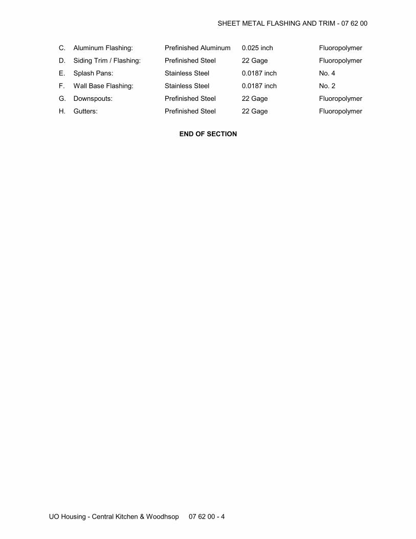
SHEET METAL FLASHING AND TRIM - 07 62 00
UO Housing - Central Kitchen & Woodhsop 07 62 00 - 4
C. Aluminum Flashing: Prefinished Aluminum 0.025 inch Fluoropolymer
D. Siding Trim / Flashing: Prefinished Steel 22 Gage Fluoropolymer
E. Splash Pans: Stainless Steel 0.0187 inch No. 4
F. Wall Base Flashing: Stainless Steel 0.0187 inch No. 2
G. Downspouts: Prefinished Steel 22 Gage Fluoropolymer
H. Gutters: Prefinished Steel 22 Gage Fluoropolymer
END OF SECTION
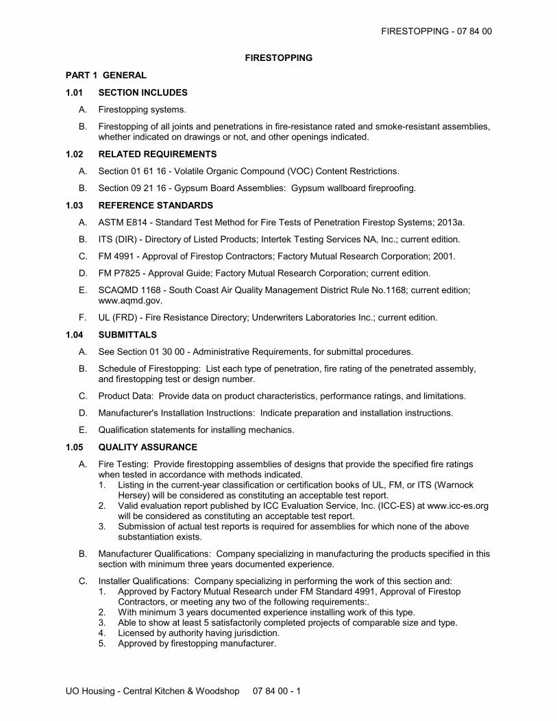
FIRESTOPPING - 07 84 00
UO Housing - Central Kitchen & Woodshop 07 84 00 - 1
FIRESTOPPING
PART 1 GENERAL
1.01 SECTION INCLUDES
A. Firestopping systems.
B. Firestopping of all joints and penetrations in fire-resistance rated and smoke-resistant assemblies,whether indicated on drawings or not, and other openings indicated.
1.02 RELATED REQUIREMENTS
A. Section 01 61 16 - Volatile Organic Compound (VOC) Content Restrictions.
B. Section 09 21 16 - Gypsum Board Assemblies: Gypsum wallboard fireproofing.
1.03 REFERENCE STANDARDS
A. ASTM E814 - Standard Test Method for Fire Tests of Penetration Firestop Systems; 2013a.
B. ITS (DIR) - Directory of Listed Products; Intertek Testing Services NA, Inc.; current edition.
C. FM 4991 - Approval of Firestop Contractors; Factory Mutual Research Corporation; 2001.
D. FM P7825 - Approval Guide; Factory Mutual Research Corporation; current edition.
E. SCAQMD 1168 - South Coast Air Quality Management District Rule No.1168; current edition;www.aqmd.gov.
F. UL (FRD) - Fire Resistance Directory; Underwriters Laboratories Inc.; current edition.
1.04 SUBMITTALS
A. See Section 01 30 00 - Administrative Requirements, for submittal procedures.
B. Schedule of Firestopping: List each type of penetration, fire rating of the penetrated assembly,and firestopping test or design number.
C. Product Data: Provide data on product characteristics, performance ratings, and limitations.
D. Manufacturer's Installation Instructions: Indicate preparation and installation instructions.
E. Qualification statements for installing mechanics.
1.05 QUALITY ASSURANCE
A. Fire Testing: Provide firestopping assemblies of designs that provide the specified fire ratingswhen tested in accordance with methods indicated.1. Listing in the current-year classification or certification books of UL, FM, or ITS (Warnock
Hersey) will be considered as constituting an acceptable test report.2. Valid evaluation report published by ICC Evaluation Service, Inc. (ICC-ES) at www.icc-es.org
will be considered as constituting an acceptable test report.3. Submission of actual test reports is required for assemblies for which none of the above
substantiation exists.
B. Manufacturer Qualifications: Company specializing in manufacturing the products specified in thissection with minimum three years documented experience.
C. Installer Qualifications: Company specializing in performing the work of this section and:1. Approved by Factory Mutual Research under FM Standard 4991, Approval of Firestop
Contractors, or meeting any two of the following requirements:.2. With minimum 3 years documented experience installing work of this type.3. Able to show at least 5 satisfactorily completed projects of comparable size and type.4. Licensed by authority having jurisdiction.5. Approved by firestopping manufacturer.
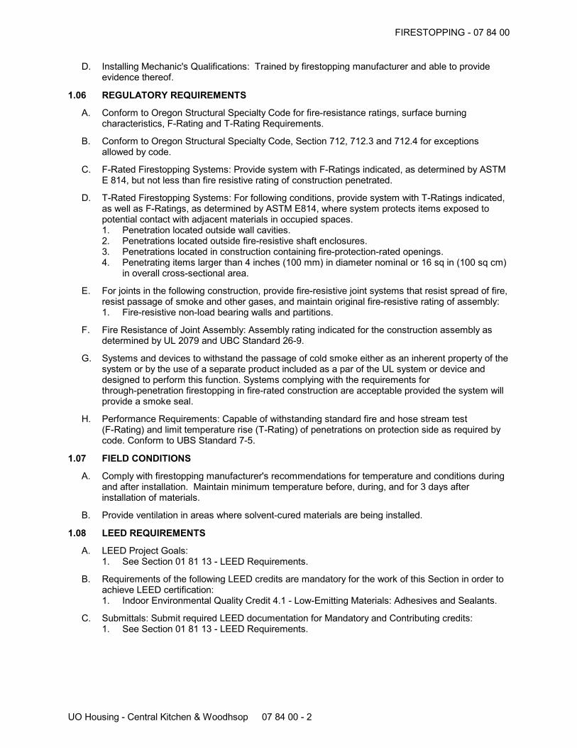
FIRESTOPPING - 07 84 00
UO Housing - Central Kitchen & Woodhsop 07 84 00 - 2
D. Installing Mechanic's Qualifications: Trained by firestopping manufacturer and able to provideevidence thereof.
1.06 REGULATORY REQUIREMENTS
A. Conform to Oregon Structural Specialty Code for fire-resistance ratings, surface burningcharacteristics, F-Rating and T-Rating Requirements.
B. Conform to Oregon Structural Specialty Code, Section 712, 712.3 and 712.4 for exceptionsallowed by code.
C. F-Rated Firestopping Systems: Provide system with F-Ratings indicated, as determined by ASTME 814, but not less than fire resistive rating of construction penetrated.
D. T-Rated Firestopping Systems: For following conditions, provide system with T-Ratings indicated,as well as F-Ratings, as determined by ASTM E814, where system protects items exposed topotential contact with adjacent materials in occupied spaces.1. Penetration located outside wall cavities.2. Penetrations located outside fire-resistive shaft enclosures.3. Penetrations located in construction containing fire-protection-rated openings.4. Penetrating items larger than 4 inches (100 mm) in diameter nominal or 16 sq in (100 sq cm)
in overall cross-sectional area.
E. For joints in the following construction, provide fire-resistive joint systems that resist spread of fire,resist passage of smoke and other gases, and maintain original fire-resistive rating of assembly:1. Fire-resistive non-load bearing walls and partitions.
F. Fire Resistance of Joint Assembly: Assembly rating indicated for the construction assembly asdetermined by UL 2079 and UBC Standard 26-9.
G. Systems and devices to withstand the passage of cold smoke either as an inherent property of thesystem or by the use of a separate product included as a par of the UL system or device anddesigned to perform this function. Systems complying with the requirements forthrough-penetration firestopping in fire-rated construction are acceptable provided the system willprovide a smoke seal.
H. Performance Requirements: Capable of withstanding standard fire and hose stream test(F-Rating) and limit temperature rise (T-Rating) of penetrations on protection side as required bycode. Conform to UBS Standard 7-5.
1.07 FIELD CONDITIONS
A. Comply with firestopping manufacturer's recommendations for temperature and conditions duringand after installation. Maintain minimum temperature before, during, and for 3 days afterinstallation of materials.
B. Provide ventilation in areas where solvent-cured materials are being installed.
1.08 LEED REQUIREMENTS
A. LEED Project Goals:1. See Section 01 81 13 - LEED Requirements.
B. Requirements of the following LEED credits are mandatory for the work of this Section in order toachieve LEED certification:1. Indoor Environmental Quality Credit 4.1 - Low-Emitting Materials: Adhesives and Sealants.
C. Submittals: Submit required LEED documentation for Mandatory and Contributing credits:1. See Section 01 81 13 - LEED Requirements.
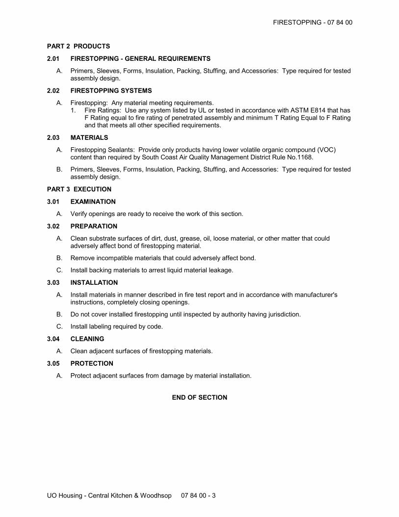
FIRESTOPPING - 07 84 00
UO Housing - Central Kitchen & Woodhsop 07 84 00 - 3
PART 2 PRODUCTS
2.01 FIRESTOPPING - GENERAL REQUIREMENTS
A. Primers, Sleeves, Forms, Insulation, Packing, Stuffing, and Accessories: Type required for testedassembly design.
2.02 FIRESTOPPING SYSTEMS
A. Firestopping: Any material meeting requirements.1. Fire Ratings: Use any system listed by UL or tested in accordance with ASTM E814 that has
F Rating equal to fire rating of penetrated assembly and minimum T Rating Equal to F Ratingand that meets all other specified requirements.
2.03 MATERIALS
A. Firestopping Sealants: Provide only products having lower volatile organic compound (VOC)content than required by South Coast Air Quality Management District Rule No.1168.
B. Primers, Sleeves, Forms, Insulation, Packing, Stuffing, and Accessories: Type required for testedassembly design.
PART 3 EXECUTION
3.01 EXAMINATION
A. Verify openings are ready to receive the work of this section.
3.02 PREPARATION
A. Clean substrate surfaces of dirt, dust, grease, oil, loose material, or other matter that couldadversely affect bond of firestopping material.
B. Remove incompatible materials that could adversely affect bond.
C. Install backing materials to arrest liquid material leakage.
3.03 INSTALLATION
A. Install materials in manner described in fire test report and in accordance with manufacturer'sinstructions, completely closing openings.
B. Do not cover installed firestopping until inspected by authority having jurisdiction.
C. Install labeling required by code.
3.04 CLEANING
A. Clean adjacent surfaces of firestopping materials.
3.05 PROTECTION
A. Protect adjacent surfaces from damage by material installation.
END OF SECTION
JOINT SEALERS - 07 90 05
UO Housing - Central Kitchen & Woodshop 07 90 05 - 1
JOINT SEALERS
PART 1 GENERAL
1.01 SECTION INCLUDES
A. Sealants and joint backing.
B. Precompressed foam sealers.
C. Preconstruction testing.
1.02 RELATED REQUIREMENTS
A. Section 07 25 00 - Weather Barriers: Sealants required in conjunction with air barriers and vaporretarders:
B. Section 08 80 00 - Glazing: Glazing sealants and accessories.
C. Section 09 21 16 - Gypsum Board Assemblies: Acoustic sealant installation.
1.03 REFERENCE STANDARDS
A. ASTM C834 - Standard Specification for Latex Sealants; 2010.
B. ASTM C919 - Standard Practice for Use of Sealants in Acoustical Applications; 2012.
C. ASTM C920 - Standard Specification for Elastomeric Joint Sealants; 2014.
D. ASTM C1193 - Standard Guide for Use of Joint Sealants; 2013.
1.04 SUBMITTALS
A. See Section 01 30 00 - Administrative Requirements, for submittal procedures.
B. Product Data: Provide data indicating sealant chemical characteristics.
C. Manufacturer's Installation Instructions: Indicate special procedures.
D. Preconstruction Field Test Reports: Indicate which sealants and joint preparation methodsresulted in optimum adhesion to joint substrates based on preconstruction testing specified inQuality Assurance below.
E. Compatibility and Adhesion Test Reports: From sealant manufacturer, including the following:1. Confirmation that joint substrates and joint-sealant backings have been tested for
compatibility and adhesion with joint sealants.2. Interpretation of test results and written recommendations for primers and substrate
preparation needed for adhesion.
1.05 QUALITY ASSURANCE
A. Manufacturer Qualifications: Company specializing in manufacturing the Products specified in thissection with minimum three years documented experience.
B. Applicator Qualifications: Company specializing in performing the work of this section withminimum three years documented experience and approved by manufacturer.
C. Compatibility and Adhesion Testing: Submit to joint sealant manufacturers, for testing indicatedbelow, samples of materials that will contact or affect joint sealants. Submit no fewer than fourpieces of each type of material, including joint substrates, shims, joint-sealant backings,secondary seals, and miscellaneous materials.1. Use manufacturer's standard test method to determine whether priming and other specific
joint preparation techniques are required to obtain rapid, optimum adhesion of joint sealantsto joint substrate.
2. Schedule sufficient time for testing and analyzing results to prevent delaying Work.3. For materials failing tests, obtain joint sealant manufacturer's written instruction for corrective
measures including use of specially formulated primers.
JOINT SEALERS - 07 90 05
UO Housing - Central Kitchen & Woodhsop 07 90 05 - 2
1.06 FIELD CONDITIONS
A. Maintain temperature and humidity recommended by the sealant manufacturer during and afterinstallation.
1.07 COORDINATION
A. Coordinate the work with all sections referencing this section.
1.08 WARRANTY
A. See Section 01 78 00 - Closeout Submittals, for additional warranty requirements.
B. Provide a five year extended correction period for sealant work.
C. Warranty: Include coverage for installed sealants and accessories which fail to achieve airtightseal and watertight seal, exhibit loss of adhesion or cohesion, or do not cure.
1.09 LEED REQUIREMENTS
A. LEED Project Goals:1. See Section 01 81 13 - LEED Requirements.
B. Requirements of the following LEED credits are mandatory for the work of this Section in order toachieve LEED certification:1. Indoor Environmental Quality Credit 4.1 - Low-Emitting Materials: Adhesives and Sealants.
C. Submittals: Submit required LEED documentation for Mandatory and Contributing credits:1. See Section 01 81 13 - LEED Requirements.
PART 2 PRODUCTS
2.01 SEALANTS
A. Type A - Elastomeric Sealant: ASTM C920; multi-component polyurethane, chemical curing,non-staining, non-bleeding, capable of continuous water immersion, non-sagging type; color asselected; meeting the following minimum requirements:1. Elongation: 25 percent2. Service Temperature Range: -40 to 180 degrees F.3. Shore A Hardness Range:+404. Products:
a. DynaTred by Pecora Corporation: www.pecora.comb. Vulkem 227 by Tremco: www.tremcosealants.com.c. Substitutions: See Section 01 60 00 - Product Requirements.
B. Type B - MS Polymer Sealant: ASTM C920, Type S, Grade NS, Class 25; single or 2-partcomponent silyl-terminated polyether, moisture curing, non-staining, non-bleeding, capable ofcontinuous water immersion, non-sagging type; multiple colors as selected to match adjacentmaterials; meeting the following minimum requirements.1. Elongation: 100 percent2. Service Temperature Range: -40 to 220 degrees F3. Shore A Hardness Range: 20 to 354. Products:
a. Sonolastic 150 by Sonneborn Building Products: www.chemrex.com.b. Substitutions: See Section 01 60 00 - Product Requirements.
C. Type C - Acoustical Sealant (Exposed): ASTM C834; single component latex, non-staining,non-bleeding, non-sagging type; multiple colors to match adjacent materials.1. Products:
a. AC20 FTR Acoustical and Insulation Sealant by Pecora Corporation: www.pecora.com.b. Sheetrock Acoustical Sealant by United States Gypsum Co: www.usg.com.c. Substitutions: See Section 01 60 00 - Product Requirements.
JOINT SEALERS - 07 90 05
UO Housing - Central Kitchen & Woodhsop 07 90 05 - 3
D. Type D - Acoustical Sealant (Concealed): Single component latex, non-staining, non-bleeding,non-hardening, non-skinning, non-sagging type; synthetic rubber type.1. Products:
a. BA-98 by Pecora Corporation.b. Tremco Acoustical Sealant by Tremco: www.tremcosealants.com.c. Acoustical Sealant by United States Gypsum Co: www.usg.com.d. #313 Sound Control Sealant by The W.W. Henry Company: www.wwhenry.com.e. Substitutions: See Section 01 60 00 - Product Requirements.
E. Type E - Silicone Sealant: Single component, mildew resistant, acid curing, silicone sealant; Class25.1. Products:
a. 786 Mildew Resistant by Dow Corning Corporation: www.dowcorningsealants.com.b. Sanitary SCS1700 by GE Silicones: www.gesilicones.com.c. Tremsil 200 by Tremco: www.tremcosealants.com.d. Substitutions: See Section 01 60 00 - Product Requirements.
F. Type F - General Purpose Sealant: Polymer; ASTM C920, Type S, Grade NS single component,paintable.1. Products:
a. Side Winder Advanced Polymer by DAP: www.dap.com.b. Substitutions: See Section 01 60 00 - Product Requirements.
2.02 GASKETS AND CLOSURES
A. Sill Seal: Foam gasket, self-adhering membrane.1. Triple Guard Energy Sill Sealer by Protecto Wrap: www.protectowrap.com.2. Substitutions: See Section 01 60 00 - Product Requirements.
B. Threshold Tape: Rubberized adhesive membrane with foam; waterproof.1. Protecto Premium Dual Guard Threshold Tape by Protecto Wrap: www.protectowrap.com.2. Substitutions: See Section 01 60 00 - Product Requirements.
2.03 ACCESSORIES
A. Primer: Non-staining type, recommended by sealant manufacturer to suit application.
B. Joint Cleaner: Non-corrosive and non-staining type, recommended by sealant manufacturer;compatible with joint forming materials.
C. Joint Backing: Round foam rod compatible with sealant; ASTM D 1667, closed cell PVC;oversized 30 to 50 percent larger than joint width.
D. Bond Breaker: Pressure sensitive tape recommended by sealant manufacturer to suit application.
PART 3 EXECUTION
3.01 EXAMINATION
A. Verify that substrate surfaces are ready to receive work.
B. Verify that joint backing and release tapes are compatible with sealant.
C. Verify that preconstruction testing has been completed.
3.02 PREPARATION
A. Remove loose materials and foreign matter that could impair adhesion of sealant.
B. Clean and prime joints in accordance with manufacturer's instructions.
C. Perform preparation in accordance with manufacturer's instructions and ASTM C1193.
D. Protect elements surrounding the work of this section from damage or disfigurement.
JOINT SEALERS - 07 90 05
UO Housing - Central Kitchen & Woodhsop 07 90 05 - 4
3.03 INSTALLATION
A. Perform work in accordance with sealant manufacturer's requirements for preparation of surfacesand material installation instructions.
B. Perform installation in accordance with ASTM C1193.
C. Perform acoustical sealant application work in accordance with ASTM C919.
D. Measure joint dimensions and size joint backers to achieve the following, unless otherwiseindicated:1. Width/depth ratio of 2:1.2. Neck dimension no greater than 1/3 of the joint width.3. Surface bond area on each side not less than 75 percent of joint width.
E. Install bond breaker where joint backing is not used.
F. Install sealant free of air pockets, foreign embedded matter, ridges, and sags.
G. Apply sealant within recommended application temperature ranges. Consult manufacturer whensealant cannot be applied within these temperature ranges.
H. Tool joints concave.
I. Precompressed Foam Sealant: Do not stretch; avoid joints except at corners, ends, andintersections; install with face 1/8 to 1/4 inch below adjoining surface.
J. Sill Sealer: Coordinate with installation of exterior wall framing.
K. Threshold Seals: Coordinate with installation of exterior door thresholds.
3.04 CLEANING
A. Clean adjacent soiled surfaces.
3.05 PROTECTION
A. Protect sealants until cured.
3.06 SCHEDULE
A. Type A - Elastomeric:1. Interior concrete slab joints.2. Exterior concrete paving joints.
B. Type B - MS Polymer:1. Sheet metal work.2. Exterior and interior perimeter of steel door and window frames.3. Perimeter of window frames.4. Joints at cabinet bases and floor.5. Other joints indicated on Drawings.
C. Type C - Acoustical Sealant:1. Perimeter of gypsum board in acoustical wall, and corner intersections.2. Perimeter of penetrations in acoustical walls and ceilings.3. Perimeter of suspended acoustical ceiling wall angles.
D. Type D - Acoustical Sealant:1. Under stud track or plate at acoustical walls, 2 beads continuous.2. Concealed perimeter of gypsum board in acoustical walls and corner intersections.3. Concealed perimeter of penetrations in acoustical walls.
E. Type E - Silicone Sealant:1. Perimeter of plumbing fixtures.
F. Type F - Polymer Sealant:
JOINT SEALERS - 07 90 05
UO Housing - Central Kitchen & Woodhsop 07 90 05 - 5
1. Exposed interior plywood wall paneling joints (Except at Wood Shop)
G. Gaskets, Sealers and Closures:1. Under exterior wall sill plates.2. Under exterior door thresholds.3. As indicated on Drawings.
END OF SECTION
HOLLOW METAL DOORS AND FRAMES - 08 11 13
UO Housing - Central Kitchen & Woodshop 08 11 13 - 1
HOLLOW METAL DOORS AND FRAMES
PART 1 GENERAL
1.01 SECTION INCLUDES
A. Non-fire-rated steel doors and frames.
B. Fire-rated steel doors and frames.
C. Thermally insulated steel doors.
D. Thermally broken exterior steel frames.
E. Accessories, including relite frames.
1.02 RELATED REQUIREMENTS
A. Section 06 10 00 - Rough Carpentry: Framed openings.
B. Section 08 14 16 - Flush Wood Doors.
C. Section 08 71 00 - Door Hardware.
D. Section 08 80 00 - Glazing: Glass for doors and relites.
E. Section 09 21 16 - Gypsum Board Assemblies: Framed openings and acoustical insulation.
F. Section 09 90 00 - Painting and Coating: Field painting.
1.03 REFERENCE STANDARDS
A. ANSI/ICC A117.1 - American National Standard for Accessible and Usable Buildings andFacilities; International Code Council; 2009.
B. ANSI A250.8 - SDI-100 Recommended Specifications for Standard Steel Doors and Frames;2003 (R2008).
C. ANSI A250.10 - Test Procedure and Acceptance Criteria for Prime Painted Steel Surfaces forSteel Doors and Frames; 1998 (R2011).
D. ASTM A653/A653M - Standard Specification for Steel Sheet, Zinc-Coated (Galvanized) orZinc-Iron Alloy-Coated (Galvannealed) by the Hot-Dip Process; 2013.
E. ASTM C1363 - Standard Test Method for Thermal Performance of Building Assemblies by Meansof a Hot Box Apparatus; 2011.
F. BHMA A156.115 - Hardware Preparation in Steel Doors and Steel Frames; 2006.
G. NAAMM HMMA 840 - Guide Specifications for Installation and Storage of Hollow Metal Doors andFrames; The National Association of Architectural Metal Manufacturers; 2007.
H. UL (BMD) - Building Materials Directory; Underwriters Laboratories Inc.; current edition.
I. UL 10C - Standard for Positive Pressure Fire Tests of Door Assemblies; Current Edition, IncludingAll Revisions.
1.04 SUBMITTALS
A. See Section 01 30 00 - Administrative Requirements for submittal procedures.
B. Product Data: Materials and details of design and construction, hardware locations,reinforcement type and locations, anchorage and fastening methods, and finishes.
C. Shop Drawings: Details of each opening, showing elevations, glazing, frame profiles, andidentifying location of different finishes, if any.
D. Installation Instructions: Manufacturer's published instructions, including any special installationinstructions relating to this project.
HOLLOW METAL DOORS AND FRAMES - 08 11 13
UO Housing - Central Kitchen & Woodhsop 08 11 13 - 2
1.05 QUALITY ASSURANCE
A. Manufacturer Qualifications: Company specializing in manufacturing the products specified in thissection with minimum five years documented experience.
B. Maintain at the project site a copy of all reference standards dealing with installation.
1.06 DELIVERY, STORAGE, AND HANDLING
A. Store in accordance with NAAMM HMMA 840.
B. Protect with resilient packaging; avoid humidity build-up under coverings; prevent corrosion.
1.07 LEED REQUIREMENTS
A. LEED Project Goals:1. See Section 01 81 13 - LEED Requirements.
B. Requirements of the following LEED credits contribute cumulatively toward LEED certification:1. Materials and Resources Credit 4 - Recycled Content.2. Materials and Resources Credit 5 - Regional Materials.
C. Submittals: Submit required LEED documentation for Mandatory and Contributing credits:1. See Section 01 81 13 - LEED Requirements.
PART 2 PRODUCTS
2.01 MANUFACTURERS
A. Steel Doors and Frames:1. Assa Abloy Ceco, Curries, or Fleming: www.assaabloydss.com.2. Windsor Republic Doors: www.republicdoor.com.3. Substitutions: See Section 01 60 00 - Product Requirements.
2.02 DOORS AND FRAMES
A. Requirements for All Doors and Frames:1. ADA Compliant: Comply with ANSI/ICC A117.1 and Oregon Structural Specialty Code.2. Door Top Closures: Flush with top of faces and edges.3. Door Edge Profile: Beveled on both edges.4. Door Texture: Smooth faces.5. Glazed Lights: Non-removable stops on non-secure side; sizes and configurations as
indicated on drawings.6. Hardware Preparation: In accordance with BHMA A156.115, with reinforcement welded in
place, in addition to other requirements specified in door grade standard.7. Galvanizing for Exterior: All components hot-dipped zinc-iron alloy-coated (galvannealed),
A60/ZF180.8. Finish: Factory primed, for field finishing.
2.03 STEEL DOORS
A. Exterior Doors :1. Grade: ANSI A250.8 Level 3, physical performance Level A, Model 2, seamless.2. Core: Polystyrene or Polyurethane.3. Thickness: 1-3/4 inches.4. Galvanizing: All components hot-dipped zinc-iron alloy-coated (galvannealed) in accordance
with ASTM A653/A653M, with manufacturer's standard coating thickness.5. Insulating Value: U-value of 0.09, when tested in accordance with ASTM C 1363 or ASTM C
518.6. Weatherstripping: Separate, see Section 08 71 00.
B. Interior Doors, Non-Fire-Rated:1. Grade: ANSI A250.8 Level 2, physical performance Level B, Model 2, seamless.2. Core: Cardboard honeycomb.
HOLLOW METAL DOORS AND FRAMES - 08 11 13
UO Housing - Central Kitchen & Woodhsop 08 11 13 - 3
3. Thickness: 1-3/4 inches.4. Finish: Factory primed, for field finishing.
C. Interior Doors, Fire-Rated:1. Grade: ANSI A250.8 Level 3, physical performance Level A, Model 2, seamless.2. Fire Rating: As indicated on Door and Frame Schedule, tested in accordance with UL 10C
("positive pressure").a. Provide units listed and labeled by UL.b. Attach fire rating label to each fire rated unit.
3. Core: As required for rating.4. Thickness: 1-3/4 inch.5. Finish: Factory primed, for field finishing.
2.04 STEEL FRAMES
A. General:1. Comply with the requirements of grade specified for corresponding door.
a. Frames for Exterior Doors: Comply with frame requirements specified in ANSI A250.8for Level 3 Doors, 14 gage.
2. Finish: Factory primed, for field finishing.3. Provide mortar guard boxes for hardware cut-outs in frames to be installed in masonry or to
be grouted.4. Frames Wider than 48 Inches: Reinforce with steel channel fitted tightly into frame head,
flush with top.
B. Exterior Door Frames: Face welded, seamless with joints filled.1. Thermal Break: True thermally-broken frame profile.2. Galvanizing: All components hot-dipped zinc-iron alloy-coated (galvannealed) in accordance
with ASTM A653/A653M, with manufacturer's standard coating thickness.3. Weatherstripping: Separate, see Section 08 71 00.
C. Interior Door Frames, Non-Fire-Rated: Fully welded type.
D. Interior Door Frames, Fire-Rated: Fully welded type.1. Fire Rating: Same as door, labeled.
2.05 ACCESSORY MATERIALS
A. Relite Frames: Cold rolled galvanized steel, 16 gage; split frame type to accept insulated glassunit; through door security bolt attachment; shop-primed finish.1. FGS-DBL by Anemostat Door Products: www.anemostat.com.2. Substitutions: See Section 01 60 00 - Product Requirements.
B. Glazing: As specified in Section 08 80 00 .
C. Silencers: Resilient rubber, fitted into drilled hole; 3 on strike side of single door, 3 on centermullion of pairs, and 2 on head of pairs without center mullions. Do not install silencers on door toreceive gasket seals.
D. Temporary Frame Spreaders: Provide for all factory- or shop-assembled frames.
E. Jamb Anchors: Provide welded floor anchor at each jamb.
F. Frame Clips: Provide frame clips appropriate for wall width and material.
2.06 FINISH MATERIALS
A. Primer: Rust-inhibiting, complying with ANSI A250.10, baked on.
B. Bituminous Coating: Asphalt emulsion or other high-build, water-resistant, resilient coating.
HOLLOW METAL DOORS AND FRAMES - 08 11 13
UO Housing - Central Kitchen & Woodhsop 08 11 13 - 4
PART 3 EXECUTION
3.01 EXAMINATION
A. Verify existing conditions before starting work.
B. Verify that opening sizes and tolerances are acceptable.
3.02 PREPARATION
A. Coat inside of frames to be installed in masonry or to be grouted, with bituminous coating, prior toinstallation.
B. Coat inside of other frames to be grouted with bituminous coating to a thickness of 1/16 inch.
3.03 INSTALLATION
A. Install in accordance with the requirements of the specified door grade standard .
B. Coordinate frame anchor placement with wall construction.
C. Coordinate installation of acoustical insulation in acoustical/sound-rated walls.
D. Coordinate installation of hardware.
E. Install relite frames in doors as recommended by manufacturer for a secure and waterproofassembly.
F. Coordinate installation of glazing.
3.04 TOLERANCES
A. Clearances Between Door and Frame: As specified in ANSI A250.8.
B. Maximum Diagonal Distortion: 1/16 in measured with straight edge, corner to corner.
3.05 ADJUSTING
A. Adjust for smooth and balanced door movement.
END OF SECTION
FLUSH WOOD DOORS - 08 14 16
UO Housing - Central Kitchen & Woodshop 08 14 16 - 1
FLUSH WOOD DOORS
PART 1 GENERAL
1.01 SECTION INCLUDES
A. Flush wood doors; flush configuration; fire rated and non-rated.
1.02 RELATED REQUIREMENTS
A. Section 06 20 00 - Finish Carpentry: Interior door and relite frames.
B. Section 08 11 13 - Hollow Metal Doors and Frames.
C. Section 08 71 00 - Door Hardware.
D. Section 08 80 00 - Glazing.
1.03 REFERENCE STANDARDS
A. AWI/AWMAC/WI (AWS) - Architectural Woodwork Standards; 2009.
B. AWI/AWMAC (QSI) - Architectural Woodwork Quality Standards Illustrated; ArchitecturalWoodwork Institute and Architectural Woodwork Manufacturers Association of Canada; 2006, 8thEd., Version 2.0.
C. NEMA LD 3 - High-Pressure Decorative Laminates; National Electrical ManufacturersAssociation; 2005.
D. NFPA 252 - Standard Methods of Fire Tests of Door Assemblies; National Fire ProtectionAssociation; 2012.
E. UL 10B - Standard for Fire Tests of Door Assemblies; Current Edition, Including All Revisions.
1.04 SUBMITTALS
A. See Section 01 30 00 - Administrative Requirements for submittal procedures.
B. Product Data: Indicate door core materials and construction; veneer species, type andcharacteristics.
C. Shop Drawings: Show doors and frames, elevations, sizes, types, swings, undercuts, beveling,blocking for hardware, factory machining, factory finishing, cutouts for glazing and other details.
D. Specimen warranty.
E. Shop Drawings: Illustrate door opening criteria, elevations, sizes, types, swings, undercutsrequired, special beveling, special blocking for hardware, factory machining criteria, factoryfinishing criteria, identify cutouts for glazing and louvers.
F. Samples: Submit two samples of door veneer, 8 x 10 inch in size illustrating wood grain, staincolor, and sheen.
G. Manufacturer's Installation Instructions: Indicate special installation instructions.
H. Warranty, executed in Owner's name.
1.05 QUALITY ASSURANCE
A. Maintain one copy of the specified door quality standard on site for review during installation andfinishing.
B. Manufacturer Qualifications: Company specializing in manufacturing the products specified in thissection with minimum five years of documented experience.
1.06 DELIVERY, STORAGE, AND HANDLING
A. Package, deliver and store doors in accordance with specified quality standard.
FLUSH WOOD DOORS - 08 14 16
UO Housing - Central Kitchen & Woodhsop 08 14 16 - 2
B. Accept doors on site in manufacturer's packaging. Inspect for damage.
C. Protect doors with resilient packaging sealed with heat shrunk plastic. Do not store in damp or wetareas; or in areas where sunlight might bleach veneer. Seal top and bottom edges with tintedsealer if stored more than one week. Break seal on site to permit ventilation.
1.07 PROJECT CONDITIONS
A. Coordinate the work with door opening construction, door frame and door hardware installation.
1.08 WARRANTY
A. See Section 01 78 00 - Closeout Submittals for additional warranty requirements.
B. Interior Doors: Provide manufacturer's warranty for the life of the installation.
C. Provide warranty for the following term:1. Interior Doors: Life of installation.
D. Include coverage for delamination of veneer, warping beyond specified installation tolerances,defective materials, and telegraphing core construction.
1.09 LEED REQUIREMENTS
A. LEED Project Goals:1. See Section 01 81 13 - LEED Requirements.
B. Requirements of the following LEED credits are mandatory for the work of this Section in order toachieve LEED certification:1. Materials and Resources Credit 7 - FSC Certified Wood.2. Indoor Environmental Quality Credit 4.4 - Low-Emitting Materials: Composite Woods and
Agrifiber Products.
C. Requirements of the following LEED credits contribute cumulatively toward LEED certification:1. Materials and Resources Credit 4 - Recycled Content.2. Materials and Resources Credit 5 - Regional Materials.
D. Submittals: Submit required LEED documentation for Mandatory and Contributing credits:1. See Section 01 81 13 - LEED Requirements.
PART 2 PRODUCTS
2.01 MANUFACTURERS
A. Wood Veneer Faced Doors: Core and veneer sourced from United States:1. Graham Wood Doors: www.grahamdoors.com.2. Lynden Door: www.lyndendoor.com.3. Algoma Hardwoods, Inc: www.algomahardwoods.com.4. Eggers Industries: www.eggersindustries.com.5. Marshfield DoorSystems, Inc: www.marshfielddoors.com.6. Oregon Door Co: www.oregondoor.com.7. Vancouver Door, Inc: www.vancouverdoorco.com.8. Substitutions: See Section 01 60 00 - Product Requirements.
B. High Pressure Decorative Laminate Faced Doors:1. Ampco Products, Inc: www.ampco.com.2. Poncraft Door Co: www.poncraft.com.3. VT Industries, Inc: www.vtindustries.com.4. Substitutions: See Section 01 60 00 - Product Requirements.
2.02 DOORS
A. All Doors - General: Comply with the following limitations:
FLUSH WOOD DOORS - 08 14 16
UO Housing - Central Kitchen & Woodhsop 08 14 16 - 3
1. Wood products including, but not limited to, plywood, fiber board, particle board andhardboard, shall not contain any added urea-formaldehyde.
2. Laminating adhesives shall not contain any added urea-formaldehyde and shall comply withVOC requirements as specified in Section 01 81 13.
3. FSC Certified Wood.
B. All Doors: See drawings for locations and additional requirements.1. Quality Level: Premium Grade, in accordance with AWI/AWMAC/WI Architectural Woodwork
Standards.2. Wood Veneer Faced Doors: 5-ply unless otherwise indicated.3. High Pressure Decorative Laminate Faced Doors: 5-ply unless otherwise indicated.
C. Interior Doors: 1-3/4 inches thick unless otherwise indicated; flush construction.1. Provide solid core doors at all locations .2. Fire Rated Doors: Tested to ratings indicated on drawings in accordance with NFPA 252, UL
10B, or UBC Standard 7-2-94 ("neutral pressure"); UL or WH (ITS) labeled without anyvisible seals when door is open.
3. Face Veneer: White Birch veneer facing, AWI Grade A, with factory transparent finish .4. High pressure decorative laminate finish where indicated on drawings.
2.03 DOOR AND PANEL CORES
A. Non-Rated Solid Core and 20 Minute Rated Doors: Type structural composite lumber core(SCLC), plies and faces as indicated above.
B. Fire Rated Doors: Mineral core, Type FD, plies and faces as indicated above; with core blockingas required to provide adequate anchorage of hardware without through-bolting.
2.04 DOOR FACINGS
A. Wood Veneer Facing for Transparent Finish: Species as specified above, veneer grade asspecified by quality standard, quarter sliced, book veneer match, running assembly match; unlessotherwise indicated.1. Vertical Edges: Same species as face veneer.2. Pairs: Pair match each pair; set match pairs within 10 feet of each other when doors are
closed.
B. High Pressure Decorative Laminate Facing for Fire Doors: NEMA LD 3, HGF; color as selected;satin finish.
C. High Pressure Decorative Laminate Facing for Non-Fire-Rated Doors: NEMA LD 3, HGS; coloras selected; satin finish.
2.05 ACCESSORIES
A. Glazing Stops: Rolled steel channel shape, mitered corners; prepared for countersink styletamper proof screws.
2.06 DOOR CONSTRUCTION
A. Fabricate doors in accordance with door quality standard specified.
B. Cores Constructed with stiles and rails:
C. Provide solid blocks at lock edge for hardware reinforcement.1. Provide solid blocking for other throughbolted hardware.
D. Fit door edge trim to edge of stiles after applying veneer facing.
E. Factory machine doors for hardware other than surface-mounted hardware, in accordance withhardware requirements and dimensions.
F. Factory fit doors for frame opening dimensions identified on shop drawings, with edge clearancesin accordance with specified quality standard.1. Exception: Doors to be field finished.
FLUSH WOOD DOORS - 08 14 16
UO Housing - Central Kitchen & Woodhsop 08 14 16 - 4
G. Provide edge clearances in accordance with the quality standard specified.
2.07 FACTORY FINISHING - WOOD VENEER DOORS
A. Finish work in accordance with AWI/AWMAC/WI Architectural Woodwork Standards, Section 5 -Finishing for Grade specified and as follows:1. Transparent:
a. System - 11, Polyurethane, Catalyzed.b. Stain: As selected by Architect.c. Sheen: Satin.
PART 3 EXECUTION
3.01 EXAMINATION
A. Verify existing conditions before starting work.
B. Verify that opening sizes and tolerances are acceptable.
C. Do not install doors in frame openings that are not plumb or are out-of-tolerance for size oralignment.
3.02 INSTALLATION
A. Install doors in accordance with manufacturer's instructions and specified quality standard.1. Install fire-rated doors in accordance with NFPA 80 requirements.
B. Factory-Finished Doors: Do not field cut or trim; if fit or clearance is not correct, replace door.
C. Use machine tools to cut or drill for hardware.
D. Coordinate installation of doors with installation of frames and hardware.
E. Coordinate installation of glazing.
3.03 TOLERANCES
A. Conform to specified quality standard for fit and clearance tolerances.
B. Conform to specified quality standard for telegraphing, warp, and squareness.
C. Maximum Vertical Distortion (Bow): 1/8 inch measured with straight edge or taut string, top tobottom, over an imaginary 36 by 84 inches surface area.
D. Maximum Width Distortion (Cup): 1/8 inch measured with straight edge or taut string, edge toedge, over an imaginary 36 by 84 inches surface area.
3.04 ADJUSTING
A. Adjust doors for smooth and balanced door movement.
B. Adjust closers for full closure.
END OF SECTION
ACCESS DOORS AND PANELS - 08 31 00
UO Housing - Central Kitchen & Woodshop 08 31 00 - 1
ACCESS DOORS AND PANELS
PART 1 GENERAL
1.01 SECTION INCLUDES
A. Wall access door and frame units.
B. Ceiling access door and frame units.
1.02 RELATED REQUIREMENTS
A. Section 09 21 16 - Gypsum Board Assemblies: Openings in partitions and ceilings.
B. Section 09 90 00 - Painting and Coating: Field paint finish.
1.03 SUBMITTALS
A. See Section 01 30 00 - Administrative Requirements, for submittal procedures.
B. Product Data: Provide sizes, types, finishes, hardware, scheduled locations, and details ofadjoining work.
C. Manufacturer's Installation Instructions: Indicate installation requirements.
D. Project Record Documents: Record actual locations of all access units.
1.04 PROJECT CONDITIONS
A. Coordinate the work with other work requiring access doors.
1.05 LEED REQUIREMENTS
A. LEED Project Goals:1. See Section 01 81 13 - LEED Requirements.
B. Requirements of the following LEED credits contribute cumulatively toward LEED certification:1. Materials and Resources Credit 4 - Recycled Content.
C. Submittals: Submit required LEED documentation for Mandatory and Contributing credits:1. See Section 01 81 13 - LEED Requirements.
PART 2 PRODUCTS
2.01 ACCESS DOORS AND PANELS
A. All Units: Factory fabricated, fully assembled units with corner joints welded, filled, and groundflush; square and without rack or warp; coordinate requirements with assemblies units are to beinstalled in.
2.02 ACCESS DOOR UNITS - WALLS AND CEILINGS - INTERIOR
A. Type AP: Door and Frame Units: Formed steel.1. Frames and flanges: 0.058 inch steel; profile compatible with wall construction.2. Door Panels (Non-rated): 0.070 inch single thickness steel sheet.3. Door Panels (Rated): 0.070 inch double steel sheet with integral non-combustible insulation
filler.4. Size: As indicated on Drawings.5. Hardware:
a. Hinges for Non-Fire-Rated Units: Concealed, constant force closure spring type.b. Hinge: 175 degree stainless steel piano hinge with removable pin.c. Lock: Screw driver slot for quarter turn cam lock, typical.d. Prime coat with baked on primer.
2.03 ACCESS DOOR UNITS - WALLS - EXTERIOR
A. Type APX: Door and Frame Units: Formed galvanized steel.
ACCESS DOORS AND PANELS - 08 31 00
UO Housing - Central Kitchen & Woodhsop 08 31 00 - 2
1. Frames and flanges: 0.03 inch steel; profile compatible with wall construction.2. Door Panels: 0.03 inch single thickness steel sheet.3. Size: As indicated on Drawings.4. Special Reinforcing: Torx security screws.5. Core: Insulated, minimum R-7.7.6. Hardware:
a. Hinges for Non-Fire-Rated Units: Concealed, constant force closure spring type.b. Latch/Lock: Tamperproof tool-operated cam latch; tool approved by Owner.c. Gasketing: Extruded neoprene, around the perimeter of the door panel.
7. Prime coat with baked on primer.8. Manufacturers:
a. Karp Associates, Inc: www.karpinc.com.b. Milcor Inc: www.milcorinc.com.c. Substitutions: See Section 01 60 00 - Product Requirements.
2.04 FABRICATION
A. Weld, fill, and grind joints to ensure flush and square unit.
PART 3 EXECUTION
3.01 EXAMINATION
A. Verify that rough openings are correctly sized and located.
3.02 INSTALLATION
A. Install units in accordance with manufacturer's instructions.
B. Install frames plumb and level in openings. Secure rigidly in place.
C. Position units to provide convenient access to the concealed work requiring access.
END OF SECTION
SECTIONAL DOORS - 08 36 13
UO Housing - Central Kitchen & Woodshop 08 36 13 - 1
SECTIONAL DOORS
PART 1 GENERAL
1.01 SECTION INCLUDES
A. Overhead sectional doors, manually operated.
B. Operating hardware and supports.
1.02 RELATED REQUIREMENTS
A. Section 05 50 00 - Metal Fabrications: Steel plate and stop opening frame.
B. Section 06 10 00 - Rough Carpentry: Rough wood framing for door opening.
C. Section 07 90 05 - Joint Sealers: Perimeter sealant and backup materials.
D. Section 08 71 00 - Door Hardware: Lock cylinders.
1.03 REFERENCE STANDARDS
A. ASTM E330/E330M - Standard Test Method for Structural Performance of Exterior Windows,Doors, Skylights and Curtain Walls by Uniform Static Air Pressure Difference; 2014.
B. DASMA 102 - American National Standard Specifications for Sectional Overhead Type Doors;Door & Access Systems Manufacturers' Association, International; 2011.
1.04 SUBMITTALS
A. See Section 01 30 00 - Administrative Requirements, for submittal procedures.
B. Shop Drawings: Indicate opening dimensions and required tolerances, connection details,anchorage spacing, hardware locations, and installation details.
C. Product Data: Show component construction, anchorage method, and hardware.
D. Manufacturer's Installation Instructions: Include any special procedures required by projectconditions.
E. Operation Data: Include normal operation, troubleshooting, and adjusting.
F. Maintenance Data: Include data for transmission, shaft and gearing, lubrication frequency, sparepart sources.
G. Warranty: Submit manufacturer warranty and ensure forms have been completed in Owner'sname and registered with manufacturer.
1.05 QUALITY ASSURANCE
A. Manufacturer Qualifications: Company specializing in manufacturing the products specified in thissection with minimum three years of experience.
B. Installer Qualifications: Company specializing in performing the work of this section with minimumthree years of experience.
1.06 WARRANTY
A. See Section 01 78 00 - Closeout Submittals for warranty requirements.
B. Correct defective Work within a five year period after Date of Substantial Completion.
1.07 LEED REQUIREMENTS
A. LEED Project Goals:1. See Section 01 81 13 - LEED Requirements.
B. Requirements of the following LEED credits contribute cumulatively toward LEED certification:1. Materials and Resources Credit 4 - Recycled Content.
SECTIONAL DOORS - 08 36 13
UO Housing - Central Kitchen & Woodhsop 08 36 13 - 2
2. Materials and Resources Credit 5 - Regional Materials.
C. Submittals: Submit required LEED documentation for Mandatory and Contributing credits:1. See Section 01 81 13 - LEED Requirements.
PART 2 PRODUCTS
2.01 MANUFACTURERS
A. Overhead Door Corporation; Product Model 422: www.overheaddoor.com.
B. Other Acceptable Manufacturers:1. Cornell Iron Works: ww.cornelliron.com.2. The Cookson Company Inc: www.cooksondoor.com.3. Substitutions: See Section 01 60 00 - Product Requirements.
2.02 STEEL DOOR COMPONENTS
A. Steel Doors: Flush steel, insulated; low headroom operating style with track and hardware;complying with DASMA 102, Commercial application.1. Performance: Withstand positive and negative wind loads equal to 1.5 times design wind
loads specified by local code without damage or permanent set, when tested in accordancewith ASTM E330/E330M, using 10 second duration of maximum load.
2. Door Nominal Thickness: 2 inches thick.3. Exterior Finish: Pre-finished with baked enamel of color as selected.4. Interior Finish: Pre-finished with baked enamel of color as selected.5. Operation: Chain hoist.6. Internal Insulation: Polystyrene, minimum R-7.35.
B. Door Panels: Flush steel construction; outer steel sheet of 0.018 inch thick, flat profile; inner steelsheet of 0.018 inch thick, flat profile; core reinforcement of 0.06 inch thick sheet steel roll formedto channel shape, rabbeted weather joints at meeting rails; insulated.
2.03 DOOR COMPONENTS
A. Track: Rolled galvanized steel, 0.090 inch thick; 2 inch wide, continuous one piece per side;galvanized steel mounting brackets 1/4 inch thick.
B. Hinge and Roller Assemblies: Heavy duty hinges and adjustable roller holders of galvanizedsteel; floating hardened steel bearing rollers, located at top and bottom of each panel, each side.
C. Lift Mechanism: Torsion spring on cross head shaft, with braided galvanized steel lifting cables.1. For Manual Operation: Requiring maximum exertion of 25 lbs force to open.
D. Sill Weatherstripping: Resilient hollow rubber strip, one piece; fitted to bottom of door panel, fulllength contact.
E. Jamb Weatherstripping: Roll formed steel section full height of jamb, fitted with resilientweatherstripping, placed in moderate contact with door panels.
F. Head Weatherstripping: EPDM rubber seal, one piece full length.
G. Panel Joint Weatherstripping: Neoprene foam seal, one piece full length.
H. Lock: Inside center mounted, adjustable keeper, spring activated latch bar with feature to retain inlocked or retracted position; interior and exterior handle.
PART 3 EXECUTION
3.01 EXAMINATION
A. Verify that wall openings are ready to receive work and opening dimensions and tolerances arewithin specified limits.
SECTIONAL DOORS - 08 36 13
UO Housing - Central Kitchen & Woodhsop 08 36 13 - 3
3.02 PREPARATION
A. Prepare opening to permit correct installation of door unit to perimeter air and vapor barrier seal.
3.03 INSTALLATION
A. Install door unit assembly in accordance with manufacturer's instructions.
B. Anchor assembly to wall construction and building framing without distortion or stress.
C. Securely brace door tracks suspended from structure. Secure tracks to structural members only.
D. Fit and align door assembly including hardware.
3.04 TOLERANCES
A. Maximum Variation from Plumb: 1/16 inch.
B. Maximum Variation from Level: 1/16 inch.
C. Longitudinal or Diagonal Warp: Plus or minus 1/8 inch from 10 ft straight edge.
D. Maintain dimensional tolerances and alignment with adjacent work.
3.05 ADJUSTING
A. Adjust door assembly for smooth operation and full contact with weatherstripping.
3.06 CLEANING
A. Clean doors and frames and glazing.
B. Remove temporary labels and visible markings.
3.07 PROTECTION
A. Protect installed products from damage during subsequent construction.
B. Do not permit construction traffic through overhead door openings after adjustment and cleaning.
END OF SECTION
DOUBLE-ACTING TRAFFIC DOORS - 08 38 15
UO Housing - Central Kitchen & Woodshop 08 38 15 - 1
DOUBLE-ACTING TRAFFIC DOORS
PART 1 GENERAL
1.01 SECTION INCLUDES
A. Double-acting self-closing swinging traffic doors.
B. Door accessories.
C. Door frames.
1.02 RELATED REQUIREMENTS
A. Section 08 71 00 - Door Hardware: Wall-mounted door stops.
1.03 SUBMITTALS
A. See Section 01 30 00 - Administrative Requirements, for submittal procedures.
B. Product Data: Manufacturer's technical information for each type of door specified, includingdetails about materials, components, profiles, gaskets, and finishes; include:1. Preparation and installation instructions and methods.2. Storage and handling requirements and recommendations.3. Operation and maintenance data.
C. Shop Drawings: Show installation details of doors and frames, including elevations andattachment.
D. Warranty: Submit manufacturer warranty and ensure that forms have been completed in Owner'sname and registered with manufacturer.
1.04 QUALITY ASSURANCE
A. Manufacturer Qualifications: Company specializing in manufacturing products of the typespecified in this section, with not less than three years of documented experience.
B. Installer Qualifications: Company specializing in performing type of work specified in this sectionwith not less than three years of documented experience and approved by manufacturer.
1.05 DELIVERY, STORAGE, AND HANDLING
A. Deliver product in manufacturer's original unopened packages with label legible and intact.
B. Store doors at project site on edge or in upright position, under cover and elevated above grade,following manufacturer's instructions.
1.06 WARRANTY
A. See Section 01 78 00 - Closeout Submittals, for additional warranty requirements.
B. Provide two year manufacturer warranty for molded polyethylene doors against damage due toworker-ridden vehicle traffic; state limitations in executed warranty.
1.07 LEED REQUIREMENTS
A. LEED Project Goals:1. See Section 01 81 13 - LEED Requirements.
B. Requirements of the following LEED credits are mandatory for the work of this Section in order toachieve LEED certification:1. Materials and Resources Credit 7 - FSC Certified Wood.2. Indoor Environmental Quality Credit 4.4 - Low-Emitting Materials: Composite Woods and
Agrifiber Products.
C. Requirements of the following LEED credits contribute cumulatively toward LEED certification:1. Materials and Resources Credit 4 - Recycled Content.
DOUBLE-ACTING TRAFFIC DOORS - 08 38 15
UO Housing - Central Kitchen & Woodhsop 08 38 15 - 2
2. Materials and Resources Credit 5 - Regional Materials.
D. Submittals: Submit required LEED documentation for Mandatory and Contributing credits:1. See Section 01 81 13 - LEED Requirements.
PART 2 PRODUCTS
2.01 RIGID AND SEMI-RIGID TRAFFIC DOORS
A. Molded Polyethylene Double-Acting Traffic Doors : Integrally molded polyethylene plastic facesand edges with urethane foam fill.1. Thickness: 1-1/2 inches.2. Faces: 1/8 inch minimum thickness; textured or pebble finish.3. Construction: Manufacturer's standard construction reinforced for durability and rigidity, with
all edges, cut-outs, and hardware preparations factory fabricated; provide view windowcut-outs with joints sealed independently of glazing or trim.
4. Hardware Preparations: Factory reinforce, machine, and prepare for all hardware includingfield installed items; provide solid blocking for each hardware item; make field cutting, drillingor tapping unnecessary.
5. Bumpers: Provide spring bumpers on both sides of doors.6. Color: As selected by Architect from manufacturer’s standard selection.7. Manufacturers:
a. Chase Doors : www.chasedoors.com.b. Rubbair Door, Inc : www.rubbair.com.c. Substitutions: See Section 01 60 00 - Product Requirements.
B. Door Assemblies: Provide double-acting, self-closing pairs of doors for installation in frameprovided by others; factory fabricated and finished, complete with hinges and specifiedaccessories.1. Door Swing: Minimum of 90 degrees each direction.2. Hinges: V-cam gravity hinges at top and pivots at bottom; mounted on bottom of header and
on top of floor; maximum rise 1-1/2 inches; vertical and horizontal adjustment in the field;manufacturer's standard lower hinge guards.
3. Hinge Guards: Manufacturer's standard material and configuration, to protect lower hingesfrom damage.
4. Exposed Metal Parts: Either stainless steel, extruded aluminum, or powder coated.5. View Windows: Provide view window in each door panel unless otherwise indicated,
centered in door width, and 48 inches, maximum, from finish floor to bottom of viewing area.6. Dimensional Tolerances: Plus or minus 1/4 inch in width and height of each panel.
C. View Windows: Factory installed glazing in molded or extruded black thermoplastic or rubbergasket; centered in door width; use single glazing unless otherwise indicated.1. Single Glazing: Acrylic glazing sheet, 1/4 inch thick, clear.
D. Impact Plates: Surface applied; factory installed.1. Bumper Plates: 30 inches high, mounted 18 inches above bottom of door.2. Push Plates: 12 inches high by 12 inches wide, mounted at leading edge of door with
centerline at 48 inches above floor.
E. Spring Bumpers: Teardrop style, polyethylene; projecting 3 inches from door panel.1. Height: 6 inches.
2.02 ACCESSORY COMPONENTS
A. Frames: Provide doors pre-hung in frames by door manufacturer; tubular steel welded frame.
B. Provide tamper proof fasteners and other hardware as recommended by manufacturer forcomplete installation.
DOUBLE-ACTING TRAFFIC DOORS - 08 38 15
UO Housing - Central Kitchen & Woodhsop 08 38 15 - 3
PART 3 EXECUTION
3.01 EXAMINATION
A. Verify that jambs and frames are square and plumb.
B. Verify that opening is ready to receive work and opening dimensions and clearances are asindicated on drawings.
C. If substrate preparation is responsibility of another installer, notify Architect of unsatisfactoryconditions before proceeding.
D. Commencement of work by installer is acceptance of opening conditions.
3.02 INSTALLATION
A. Install doors with clearances, anchors, hardware, and accessories according to themanufacturer's instructions and as specified.
B. Install doors plumb, level, and properly aligned.
3.03 ADJUSTING
A. Clean and lubricate operating parts.
B. Adjust doors to open and close smoothly and freely without binding and for proper fit of seals.
3.04 CLEANING
A. Clean surfaces using methods as recommended by manufacturer.
END OF SECTION
VINYL WINDOWS - 08 53 13
UO Housing - Central Kitchen & Woodshop 08 53 13 - 1
VINYL WINDOWS
PART 1 GENERAL
1.01 SECTION INCLUDES
A. Vinyl-framed, factory-glazed windows.
B. Operating hardware.
C. Insect screens.
D. Perimeter sealant.
1.02 RELATED REQUIREMENTS
A. Section 07 90 05 - Joint Sealers: Perimeter sealant and back-up materials.
B. Section 08 80 00 - Glazing.
1.03 REFERENCE STANDARDS
A. AAMA/WDMA/CSA 101/I.S.2/A440 - North American Fenestration Standard/Specification forwindows, doors, and skylights; American Architectural Manufacturers Association/Window & DoorManufacturers Association/Canadian Standards Association; 2011.
B. AAMA 701/702 - Voluntary Specification for Pile Weatherstripping and Replaceable FenestrationWeatherseals; American Architectural Manufacturers Association; 2011.
C. ASTM F588 - Standard Test Methods for Measuring the Forced Entry Resistance of WindowAssemblies, Excluding Glazing Impact; 2014.
D. NFRC 100 - Procedure for Determining Fenestration Product U-factors; 2010.
E. NFRC 200 - Procedure for Determining Fenestration Product Solar Heat Gain Coefficient andVisible Transmittance at Normal Incidence.
F. NFRC 300 - Test Method for Determining the Solar Optical Properties of Glazing Materials andSystems.
G. NFRC 400 - Procedure for Determining Fenestration Product Air Leakage.
H. NFRC 500 - Procedure for Determining Fenestration Product Condensation Resistance Values.
1.04 PERFORMANCE REQUIREMENTS
A. Performance Requirements: As specified in PART 2, with the following additional requirements:
B. Forced Entry Resistance: Conform to ASTM F588 requirements for performance level 10 forwindow type B.
C. System Design: Design and size components to withstand dead and live loads caused bypressure and suction of wind acting normal to plane of window.
D. Deflection: Limit member deflection to 1/200 of the longer dimension with full recovery of glazingmaterials.
E. Air Infiltration: Limit air infiltration through assembly to 0.3 cu ft/min/sq ft of wall area, measuredat a reference differential pressure across assembly of 1.57 psf as measured in accordance withASTM E283.
F. Water Leakage: None, when measured in accordance with ASTM E331.
G. Design Temperature Range: 120 F degrees.
VINYL WINDOWS - 08 53 13
UO Housing - Central Kitchen & Woodhsop 08 53 13 - 2
1.05 ADMINISTRATIVE REQUIREMENTS
1.06 SUBMITTALS
A. See Section 01 30 00 - Administrative Requirements, for submittal procedures.
B. Product Data: Provide component dimensions, anchorage and fasteners, glass, internal drainagedetails.
C. Shop Drawings: Indicate opening dimensions, framed opening tolerances, affected related work,installation requirements.
D. Warranty: Submit manufacturer warranty and ensure that forms have been completed in Owner'sname and registered with manufacturer.
1.07 QUALITY ASSURANCE
A. Manufacturer Qualifications: Company specializing in manufacturing products specified in thissection, with not less than five years of documented experience.
B. Installer Qualifications: Company specializing in performing the work of this section with minimumthree years experience.
1.08 DELIVERY, STORAGE, AND HANDLING
A. Protect finished surfaces with wrapping. Do not use adhesive papers or sprayed coatings thatbond when exposed to sunlight or weather.
B. Jig, brace, and box the window frame assemblies for transport to minimize flexing of members orjoints.
1.09 FIELD CONDITIONS
A. Do not install sealants when ambient temperature is less than 40 degrees F.
B. Maintain this minimum temperature during and after installation of sealants.
1.10 WARRANTY
A. See Section 01 78 00 - Closeout Submittals, for additional warranty requirements.
B. Correct defective Work within a five year period after Date of Substantial Completion.
C. Provide five year manufacturer warranty for insulated glass units from seal failure, interpanedusting or misting, and replacement of same. Include coverage for degradation of color finish.
1.11 LEED REQUIREMENTS
A. LEED Project Goals:1. See Section 01 81 13 - LEED Requirements.
B. Requirements of the following LEED credits contribute cumulatively toward LEED certification:1. Materials and Resources Credit 4 - Recycled Content.2. Materials and Resources Credit 5 - Regional Materials.
C. Submittals: Submit required LEED documentation for Mandatory and Contributing credits:1. See Section 01 81 13 - LEED Requirements.
PART 2 PRODUCTS
2.01 MANUFACTURERS
A. Vinyl Windows:1. Montecito Series by Milgard Manufacturing, Inc: www.Milgard.com.2. Substitutions: See Section 01 60 00 - Product Requirements.
VINYL WINDOWS - 08 53 13
UO Housing - Central Kitchen & Woodhsop 08 53 13 - 3
2.02 VINYL WINDOWS
A. Performance Requirements: Provide products that comply with the following:1. Comply with AAMA/WDMA/CSA 101/I.S.2/A440 requirements in accordance with the
following:2. Performance Validation: Windows shall comply with AAMA/WDMA/CSA 101/I.S.2/A440
performance requirements as indicated by having AAMA, WDMA, or CSA certified label, oran independent test report for indicated products itemizing compliance and acceptable byauthorities having jurisdiction.
2.03 COMPONENTS
A. Windows: Extruded, hollow, tubular, ultra-violet resistant polyvinyl chloride (PVC) with integralcolor; factory fabricated; with vision glass, related flashings, anchorage and attachment devices.1. Configuration: Fixed, non-operable and horizontal sliding sash; multiple ganged units as
indicated on Drawings.2. Color: Tan.
B. Frame Depth: 3-1/4 inch.
C. Insect Screens: Woven fiberglass mesh; 14/18 mesh size.1. Color: Gray.
D. Operable Sash Weather Stripping: Resilient PVC; permanently resilient, profiled to effect weatherseal.
E. Fasteners: Stainless steel.
F. Glass and Glazing Materials: As specified in Section 08 80 00 of Types described below:1. Glass in Exterior Lights: ISGU, insulated safety glass units and IGU, Insulated glass units.2. Safety glazing as required by code.
2.04 SEALANT MATERIALS
A. Perimeter Sealant and Backing Materials: Type B - MS Polymer as specified in Section 07 90 05.
2.05 HARDWARE
A. Horizontal Sliding Sash: Rigid PVC interfacing tracks, nylon rollers with stainless steel axels andopening stops in head and sill track as required.
B. Sash lock: Lever handle and keeper with cam lock, provide at least one for each operating sash.
2.06 FABRICATION
A. Fabricate framing, mullions and sash members with fusion welded corners and joints, in a rigid jig. Supplement frame sections with internal steel reinforcement where required for structural rigidity.
B. Form sills in one piece. Slope sills for wash.
C. Form snap-in glass stops, closure molds, weather stops, and flashings of extruded PVC for tightfit into window frame section.
D. Form weather stop flange to perimeter of unit.
E. Fabricate components with minimum clearances and shim spacing around perimeter of assembly,yet enabling installation and dynamic movement of perimeter seal.
F. Arrange fasteners to be concealed from view.
G. Permit internal drainage weep holes and channels to migrate moisture to exterior. Provideinternal drainage of glazing spaces to exterior through weep holes.
H. Assemble insect screen frame, miter and reinforced frame corners. Fit mesh taut into frame andsecure. Fit frame with four spring loaded steel pin retainers.
VINYL WINDOWS - 08 53 13
UO Housing - Central Kitchen & Woodhsop 08 53 13 - 4
I. Double weatherstrip operable units.
J. Factory glaze window units.
PART 3 EXECUTION
3.01 EXAMINATION
A. Verify wall openings and adjoining air and vapor seal materials are ready to receive this work.
3.02 INSTALLATION
A. Install window unit assemblies in accordance with manufacturers instructions and applicablebuilding codes.
B. Attach window frame and shims to perimeter opening to accommodate construction tolerancesand other irregularities as necessary.
C. Align window plumb and level, free of warp or twist, and maintain dimensional tolerances andalignment with adjacent work.
D. Provide thermal isolation where components penetrate or disrupt building insulation. Pack fibrousinsulation in shim spaces at perimeter of assembly to maintain continuity of thermal barrier.
E. Coordinate attachment and seal of perimeter air and vapor barrier materials.
F. Install operating hardware.
G. Install perimeter sealant and backing materials in accordance with Section 07 90 05.
3.03 TOLERANCES
A. Maximum Variation from Level or Plumb: 0.06 inches every 3 ft non-cumulative or 0.5 inches per100 ft, whichever is less.
3.04 ADJUSTING
A. Adjust hardware for smooth operation and secure weathertight closure.
3.05 CLEANING
A. Remove protective material from pre-finished surfaces.
B. Wash surfaces by method recommended and acceptable to sealant and window manufacturer;rinse and wipe surfaces clean.
C. Remove excess sealant by moderate use of mineral spirits or other solvent acceptable to sealantmanufacturer and appropriate for application indicated.
END OF SECTION
DOOR HARDWARE - 08 71 00
UO Housing - Central Kitchen & Woodshop 08 71 00 - 1
DOOR HARDWARE
PART 1 GENERAL
1.01 SECTION INCLUDES
A. Installation of Owner furnished door hardware.
B. Installation of hardware for wood and hollow steel doors.
1.02 RELATED REQUIREMENTS
A. Section 01 10 00 - Summary: Description of Owner Furnished Contractor Installed items.
B. Section 08 11 13 - Hollow Metal Doors and Frames.
C. Section 08 14 16 - Flush Wood Doors.
D. Section 08 38 15 - Double-Acting Doors: Hardware furnished with door.
1.03 REFERENCE STANDARDS
A. DHI (LOCS) - Recommended Locations for Architectural Hardware for Standard Steel Doors andFrames; Door and Hardware Institute; 2004.
B. DHI WDHS.3 - Recommended Locations for Architectural Hardware for Flush Wood Doors; Doorand Hardware Institute; 1993; also in WDHS-1/WDHS-5 Series, 1996.
C. NFPA 80 - Standard for Fire Doors and Other Opening Protectives; 2013.
1.04 ADMINISTRATIVE REQUIREMENTS
A. Coordinate the manufacture, fabrication, and installation of products onto which door hardwarewill be installed.
B. Furnish templates for door and frame preparation to manufacturers and fabricators of productsrequiring internal reinforcement for door hardware.
1.05 SUBMITTALS
A. See Section 01 30 00 - Administrative Requirements, for submittal procedures.
B. Product Data (By Owner): Manufacturer's catalog literature for each type of hardware, marked toclearly show products to be furnished for this project.
C. Hardware Schedule (By Owner): Detailed listing of each item of hardware to be installed on eachdoor. Use door numbering scheme as included in the Contract Documents. Identify electricallyoperated items and include power requirements.
D. Project Record Documents: Record actual locations of concealed equipment, services, andconduit.
1.06 DELIVERY, STORAGE, AND HANDLING
A. Package hardware items individually; label and identify each package with door opening code tomatch hardware schedule.
B. Accept delivery of Owner Furnished hardware.
1.07 COORDINATION
A. Coordinate the work with other directly affected sections involving manufacture or fabrication ofinternal reinforcement for door hardware.
DOOR HARDWARE - 08 71 00
UO Housing - Central Kitchen & Woodhsop 08 71 00 - 2
PART 2 PRODUCTS
PART 3 EXECUTION
3.01 INSTALLATION
A. Install hardware in accordance with manufacturer's instructions and applicable codes.
B. Use templates provided by hardware item manufacturer.
C. Do not install surface mounted items until finishes applied to substrate are complete.
D. Install hardware on fire-rated doors and frames in accordance with code and NFPA 80.
E. Mounting heights for hardware from finished floor to center line of hardware item: As listed inSchedule, unless otherwise noted:1. For steel doors and frames: Comply with DHI "Recommended Locations for Architectural
Hardware for Steel Doors and Frames."2. For steel doors and frames: See Section 08 11 13.3. For wood doors: Comply with DHI "Recommended Locations for Architectural Hardware for
Wood Flush Doors."
3.02 ADJUSTING
A. Adjust work under provisions of Section 01 70 00.
B. Adjust hardware for smooth operation.
C. Adjust gasketing for complete, continuous seal; replace if unable to make complete seal.
3.03 CLEANING
A. Clean adjacent surfaces soiled by hardware installation. Clean finished hardware permanufacturer's instructions after final adjustments has been made. Replace items that cannot becleaned to manufacturer's level of finish quality at no additional cost.
3.04 PROTECTION
A. Protect finished Work under provisions of Section 01 70 00.
B. Do not permit adjacent work to damage hardware or finish.
HARDWARE SETS
4.01 HARDWARE GROUPS
A. Group 1 - Office (109B-A, 109C-A, 109D-A, 111-A) 3 Ea Hinges 1 Ea Lockset, Office 1 Ea Stop, Wall
B. Group 2 - Office (101-B) 3 Ea Hinges 1 Ea Lockset, Office 1 Ea Stop, Overhead
C. Group 3 - Passage (101-H, 106-A, 109A-A, 117-C) 3 Ea Hinges 1 Ea Lockset, Passage 1 Ea Stop, Overhead
D. Group 4 - Passage (112-A) 3 Ea Hinges 1 Ea Lockset, Passage 1 Ea Stop, Overhead
DOOR HARDWARE - 08 71 00
UO Housing - Central Kitchen & Woodhsop 08 71 00 - 3
1 Set Seals 1 EA Door Bottom Seal
E. Group 5 - Passage (112-A) 3 Ea Hinges 1 Ea Lockset, Passage 1 Ea Stop, Wall 1 Set Seals 1 EA Door Bottom Seal
F. Group 6 - Storage (H102-C, 128-A) 3 Ea Hinges 1 Ea Lockset, Storage 1 Ea Stop, Overhead
G. Group 7 - Restroom (101D-A, 103-A, 104-A, 107-A, 108-A) 3 Ea Hinges 1 Ea Mortise Latchset with Indicator 1 Ea Stop, Wall 1 Set Seals 1 Ea Door Bottom Seal
H. Group 8 - Storage, Fire Rated (121A-A) 3 Ea Hinges 1 Ea Lockset, Storage 1 Ea Closer 1 Set Seals 1 Ea Door Bottom Seal
I. Group 9 - Storage, Fire Rated (121A-A) 3 Ea Hinges 1 Ea Lockset, Storage 1 Ea Closer 1 Ea Stop, Wall 1 Set Seals 1 Ea Door Bottom Seal
J. Group 10 - Entry/Access Control (102-A, H102-A, H102-B) 3 Ea Hinges 1 Ea Lockset, for keyless entry 1 Ea Closer 1 Ea Stop, Wall 1 Set Seals 1 Ea Door Bottom Seal
K. Group 11 - Pair/Passage/Interior (101-E/D, 101-G/G, 101B-A/B) 3 Ea Hinges 1 Ea Lockset, Passage 1 Ea Stop, Overhead 1 Ea Coordinator 1 Sets Seals 1 Ea Door Bottom Seal
L. Group 12 - Pair/Passage/Interior (117-A/B) 3 Ea Hinges 1 Ea Lockset, Passage 1 Ea Stop, Overhead 1 Ea Coordinator
M. Group 13 - Double Acting Pair/Interior (110A-A/B, 116-C/D) 3 Ea Hinges 1 Ea Protection Plates
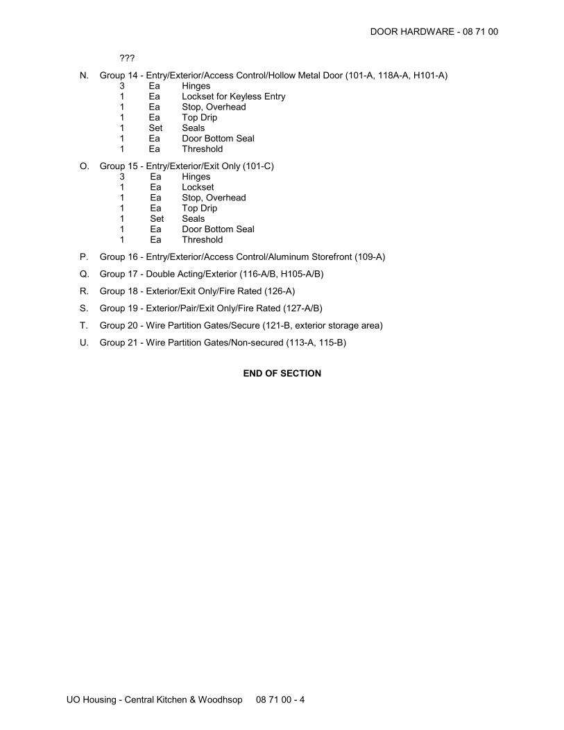
DOOR HARDWARE - 08 71 00
UO Housing - Central Kitchen & Woodhsop 08 71 00 - 4
???
N. Group 14 - Entry/Exterior/Access Control/Hollow Metal Door (101-A, 118A-A, H101-A) 3 Ea Hinges 1 Ea Lockset for Keyless Entry 1 Ea Stop, Overhead 1 Ea Top Drip 1 Set Seals 1 Ea Door Bottom Seal 1 Ea Threshold
O. Group 15 - Entry/Exterior/Exit Only (101-C) 3 Ea Hinges 1 Ea Lockset 1 Ea Stop, Overhead 1 Ea Top Drip 1 Set Seals 1 Ea Door Bottom Seal 1 Ea Threshold
P. Group 16 - Entry/Exterior/Access Control/Aluminum Storefront (109-A)
Q. Group 17 - Double Acting/Exterior (116-A/B, H105-A/B)
R. Group 18 - Exterior/Exit Only/Fire Rated (126-A)
S. Group 19 - Exterior/Pair/Exit Only/Fire Rated (127-A/B)
T. Group 20 - Wire Partition Gates/Secure (121-B, exterior storage area)
U. Group 21 - Wire Partition Gates/Non-secured (113-A, 115-B)
END OF SECTION
GLAZING - 08 80 00
UO Housing - Central Kitchen & Woodshop 08 80 00 - 1
GLAZING
PART 1 GENERAL
1.01 SECTION INCLUDES
A. Glass.
B. Glazing compounds and accessories.
1.02 RELATED REQUIREMENTS
A. Section 07 90 05 - Joint Sealers: Sealant and back-up material.
B. Section 08 11 13 - Hollow Metal Doors and Frames: Glazed exterior doors.
C. Section 08 14 16 - Flush Wood Doors: Glazed doors.
D. Section 08 53 13 - Vinyl Windows.
1.03 REFERENCE STANDARDS
A. 16 CFR 1201 - Safety Standard for Architectural Glazing Materials; current edition.
B. ASTM C864 - Standard Specification for Dense Elastomeric Compression Seal Gaskets, SettingBlocks, and Spacers; 2005 (Reapproved 2011).
C. ASTM C1036 - Standard Specification for Flat Glass; 2011e1.
D. ASTM C1048 - Standard Specification for Heat-Strengthened and Fully Tempered Flat Glass;2012.
E. ASTM E2190 - Standard Specification for Insulating Glass Unit Performance and Evaluation;2010.
F. GANA (GM) - GANA Glazing Manual; Glass Association of North America; 2009.
1.04 ADMINISTRATIVE REQUIREMENTS
A. Preinstallation Meeting: Convene a preinstallation meeting one week before starting work of thissection; require attendance by all affected installers.
1.05 PERFORMANCE REQUIREMENTS
A. Select type and thickness of exterior glass to withstand dead loads and wind loads acting normalto plane of glass at design pressures calculated in accordance with Oregon Structural Specialtycode.1. Use the procedure specified in ASTM E1300 to determine glass type and thickness.2. Limit glass deflection to 1/200 or flexure limit of glass, whichever is less, with full recovery of
glazing materials.3. Thicknesses listed are minimum.
1.06 SUBMITTALS
A. See Section 01 30 00 - Administrative Requirements, for submittal procedures.
B. Product Data on Glass Types: Provide structural, physical and environmental characteristics, sizelimitations, special handling or installation requirements.
C. Product Data on Glazing Compounds: Provide chemical, functional, and environmentalcharacteristics, limitations, special application requirements. Identify available colors.
D. Samples: Submit two samples 12 inch in size of glass units, showing coloration and design.
E. Certificates: Certify that products meet or exceed specified requirements.
F. Maintenance Materials: Furnish the following for Owner's use in maintenance of project.1. See Section 01 60 00 - Product Requirements, for additional provisions.
GLAZING - 08 80 00
UO Housing - Central Kitchen & Woodhsop 08 80 00 - 2
2. Extra Insulating Glass Units: One of each glass size and each glass type.
1.07 QUALITY ASSURANCE
A. Perform Work in accordance with GANA Glazing Manual and FGMA Sealant Manual for glazinginstallation methods.
B. Installer Qualifications: Company specializing in performing the work of this section with minimumthree years documented experience.
1.08 PRE-INSTALLATION MEETING
A. Convene one week before starting work of this section.
1.09 FIELD CONDITIONS
A. Do not install glazing when ambient temperature is less than 50 degrees F.
B. Maintain minimum ambient temperature before, during and 24 hours after installation of glazingcompounds.
1.10 WARRANTY
A. See Section 01 78 00 - Closeout Submittals, for additional warranty requirements.
B. Sealed Insulating Glass Units: Provide a ten (10) year warranty to include coverage for sealfailure, interpane dusting or misting, including replacement of failed units.
1.11 LEED REQUIREMENTS
A. LEED Project Goals:1. See Section 01 81 13 - LEED Requirements.
B. Requirements of the following LEED credits are mandatory for the work of this Section in order toachieve LEED certification:1. Indoor Environmental Quality Credit 4.1 - Low-Emitting Materials: Adhesives and Sealants.
C. Requirements of the following LEED credits contribute cumulatively toward LEED certification:1. Materials and Resources Credit 4 - Recycled Content.2. Materials and Resources Credit 5 - Regional Materials.
D. Submittals: Submit required LEED documentation for Mandatory and Contributing credits:1. See Section 01 81 13 - LEED Requirements.
PART 2 PRODUCTS
2.01 GLAZING TYPES
2.02 GLASS MATERIALS
A. Float Glass: All glazing is to be float glass unless otherwise indicated.1. Annealed Type: ASTM C 1036, Type I, transparent flat, Class 1 clear, Quality Q3 (glazing
select).2. Heat-Strengthened and Fully Tempered Types: ASTM C1048.3. Thicknesses: As indicated; for exterior glazing comply with specified requirements for wind
load design regardless of specified thickness.
B. Clear Float Glass (Type CG): Clear, annealed.1. Comply with ASTM C 1036, Type I, transparent flat, Class 1 clear, Quality Q3 (glazing
select).2. Comply with ASTM C 1048.3. Thickness: 1/4 inch (6 mm) minimum.
C. Clear Safety Glass (Type CSG): Clear; fully tempered.1. Comply with ASTM C 1036, Type I, transparent flat, Class 1 clear, Quality Q3 (glazing select)
and ASTM C 1048.
GLAZING - 08 80 00
UO Housing - Central Kitchen & Woodhsop 08 80 00 - 3
2. Comply with 16 CFR 1201 test requirements for Category II.3. Thickness: 1/4 inch (6 mm) minimum.
D. Low E Glass : Float type, annealed and tempered, clear.1. High performance, triple silver layer Low E coating.2. 1/4 inch (6 mm) minimum thick.
2.03 SEALED INSULATING GLASS UNITS
A. Sealed Insulating Glass Units: Types as indicated.1. Locations: Exterior, except as otherwise indicated.2. Durability: Certified by an independent testing agency to comply with ASTM E 2190.3. Edge Spacers: Stainless steel, bent and soldered corners.4. Edge Seal: Glass to elastomer with supplementary silicone sealant.5. Purge interpane space with dry hermetic air.
B. Insulated Glass Units (Type IGU): Double pane with glass to elastomer edge seal.1. Outer pane of Low E clear glass (1/4 inch thick), and inner pane of clear glass2. Place low E coating on No. 2 surface within the unit.3. Durability: Certified by an independent testing agency to comply with ASTM E 2190.4. Purge interpane space with dry hermetic air.5. U Value (Center of Glass): 0.29 maximum.6. Shading Coefficient: 0.31 maximum.7. Solar Heat Gain Coefficient: 0.27.8. Visible Light Transmittance: 64 percent.9. Total unit thickness of 1 inch minimum.10. Product:
a. LoE3-366 insulated glass units with XL Edge by Cardinal Glass Industries:www.cadinalcorp.com.
b. Substitutions: See Section 01 60 00 - Product Requirements.
C. Insulated Safety Glass Units (Type ISGU): Double pane with glass to elastomer edge seal.1. Outer pane of Low E clear safety glass (1/4 inch thick), inner pane of clear safety glass (3/16
inch thick).2. Place low E coating on No.2 surface within the unit.3. Durability: Certified by an independent testing agency to comply with ASTM E 2190.4. Purge interpane space with dry hermetic air.5. U Value: 0.29 maximum.6. Shading Coefficient: 0.31 maximum.7. Solar Heat Gain Coefficient: 0.27.8. Visible Light Transmittance: 64 percent.9. Total unit thickness of 1 inch minimum.10. Product:
a. LoE3-366 insulated glass units with XL Edge by Cardinal Glass Industries:www.cadinalcorp.com.
b. Substitutions: See Section 01 60 00 - Product Requirements.
2.04 GLAZING ACCESSORIES
A. Setting Blocks: Silicone, 80 to 90 Shore A durometer hardness, ASTM C864 Option I. Length of0.1 inch for each square foot of glazing or minimum 4 inch x width of glazing rabbet space minus1/16 inch x height to suit glazing method and pane weight and area.
B. Spacer Shims: Neoprene, 50 to 60 Shore A durometer hardness, ASTM C 864 Option I.Minimum 3 inch long x one half the height of the glazing stop x thickness to suit application, selfadhesive on one face.
C. Glazing Tape: Preformed butyl compound with integral resilient tube spacing device; 10 to 15Shore A durometer hardness; coiled on release paper; size as required; black color.
GLAZING - 08 80 00
UO Housing - Central Kitchen & Woodhsop 08 80 00 - 4
PART 3 EXECUTION
3.01 EXAMINATION
A. Verify that openings for glazing are correctly sized and within tolerance.
B. Verify that surfaces of glazing channels or recesses are clean, free of obstructions that mayimpede moisture movement, weeps are clear, and ready to receive glazing.
3.02 PREPARATION
3.03 INSTALLATION - HOLLOW METAL DOORS
A. Method recommended by hollow metal door manufacturer.
3.04 INSTALLATION - WOOD DOORS AND RELITES - DRY METHOD (TAPE AND TAPE)
A. Cut glazing tape to length and set against permanent stops, projecting 1/16 inch above sight line.
B. Place setting blocks at 1/4 points with edge block no more than 6 inches from corners.
C. Rest glazing on setting blocks and push against tape for full contact at perimeter of pane or unit.
D. Place glazing tape on free perimeter of glazing in same manner described above.
E. Install removable stop without displacement of tape. Exert pressure on tape for full continuouscontact.
F. Knife trim protruding tape.
3.05 CLEANING
A. Remove glazing materials from finish surfaces.
B. Remove labels after Work is complete.
C. Clean glass and adjacent surfaces.
3.06 PROTECTION
A. After installation, mark pane with an 'X' by using removable plastic tape or paste; do not mark heatabsorbing or reflective glass units.
END OF SECTION
LOUVERS - 08 91 00
UO Housing - Central Kitchen & Woodshop 08 91 00 - 1
LOUVERS
PART 1 GENERAL
1.01 SECTION INCLUDES
A. Louvers, frames, and accessories.
1.02 RELATED REQUIREMENTS
A. Section 06 10 00 - Rough Carpentry: Exterior wall framing.
B. Section 07 46 46 - Fiber Cement Siding: Exterior wall finish.
C. Section 07 62 00 - Sheet Metal Flashing and Trim.
D. Section 07 90 05 - Joint Sealers.
E. Section 08 11 13 - Hollow Metal Doors and Frames: Frames to accept louvers.
1.03 REFERENCE STANDARDS
A. AAMA 2604 - Voluntary Specification, Performance Requirements and Test Procedures for HighPerformance Organic Coatings on Aluminum Extrusions and Panels; 2013.
B. AMCA 500-L - Laboratory Methods of Testing Louvers for Rating; Air Movement and ControlAssociation International, Inc.; 2012.
C. AMCA 511 - Certified Ratings Program Product Rating Manual for Air Control Devices; 2013.
1.04 SUBMITTALS
A. See Section 01 30 00 - Administrative Requirements, for submittal procedures.
B. Product Data: Provide data describing design characteristics, maximum recommended airvelocity, design free area, materials and finishes.
C. Product Data: Provide data on actuator.
D. Shop Drawings: Indicate louver layout plan and elevations, opening and clearance dimensions,tolerances; head, jamb and sill details; blade configuration, screens, blankout areas required, andframes.
E. Samples: Submit two samples 2 by 2 inches in size illustrating finish and color of exterior andinterior surfaces.
F. Test Reports: Independent agency reports showing compliance with specified performancecriteria.
1.05 QUALITY ASSURANCE
A. Manufacturer Qualifications: Company specializing in manufacturing products of the typespecified in this section, with minimum three years of documented experience.
1.06 PROJECT CONDITIONS
A. Coordinate work of this section with installation of siding and flashing.
B. Coordinate work of this section with installation of mechanical ductwork .
1.07 WARRANTY
A. See Section 01 78 00 - Closeout Submittals, for additional warranty requirements.
B. Provide twenty year manufacturer warranty against distortion, metal degradation, and failure ofconnections.
LOUVERS - 08 91 00
UO Housing - Central Kitchen & Woodhsop 08 91 00 - 2
1.08 LEED REQUIREMENTS
A. LEED Project Goals:1. See Section 01 81 13 - LEED Requirements.
B. Requirements of the following LEED credits contribute cumulatively toward LEED certification:1. Materials and Resources Credit 4 - Recycled Content.
C. Submittals: Submit required LEED documentation for Mandatory and Contributing credits:1. See Section 01 81 13 - LEED Requirements.
PART 2 PRODUCTS
2.01 MANUFACTURERS
A. Fixed Wall Louvers:1. Type K6844 by The Airolite Company: www.airolite.com.2. Substitutions: See Section 01 60 00 - Product Requirements.
2.02 LOUVERS
A. Louvers, General: Factory fabricated and assembled, complete with frame, mullions, andaccessories; AMCA Certified under AMCA 511.1. Wind Load Resistance: Design to resist positive and negative wind load of 25 psf without
damage or permanent deformation.2. Intake Louvers: Design to allow maximum of 0.01 oz/sq ft water penetration at calculated
intake design velocity based on design air flow and actual free area, when tested inaccordance with AMCA 500-L.
3. Drainable Blades: Continuous rain stop at front or rear of blade aligned with vertical gutterrecessed into both jambs of frame.
4. Screens: Provide bird screens at intake and exhaust louvers.
B. Stationary Louvers : Horizontal blade, extruded aluminum construction, with concealedintermediate mullions.1. Free Area: 50 percent, minimum.2. Blades: Drainable; 45 degree angle.3. Frame: 4 inches deep, channel profile; corner joints mitered and, with continuous recessed
caulking channel each side.4. Metal Thickness: Frame 0.081 inch; blades 0.081 inch.5. Finish: Fluoropolymer coating, finished after fabrication.6. Color: As selected from manufacturer's standard colors.
2.03 MATERIALS
A. Extruded Aluminum: ASTM B221 (ASTM B221M), .
B. Bird Screen: Interwoven wire mesh of steel, 0.063 inch diameter wire, 1/2 inch open weave,diagonal design.
2.04 ACCESSORIES
A. Screens: Frame of same material as louver, with reinforced corners; removable, screw attached;installed on inside face of louver frame.
B. Fasteners and Anchors: Galvanized steel.
C. Head and Sill Flashings: See Section 07 62 00.
D. Sealant: Type B - MS Polymer Sealant, as specified in Section 07 90 05.
2.05 FINISHES
A. Polyvinylidene Fluoride Coating: Minimum 70 percent Kynar 500/Hylar 500 resin, two coat finish,complying with AAMA 2604.
LOUVERS - 08 91 00
UO Housing - Central Kitchen & Woodhsop 08 91 00 - 3
PART 3 EXECUTION
3.01 EXAMINATION
A. Verify that prepared openings and flashings are ready to receive work and opening dimensionsare as indicated on shop drawings.
B. Verify that field measurements are as indicated.
3.02 INSTALLATION
A. Install louver assembly in accordance with manufacturer's instructions.
B. Coordinate with installation of flashings by others.
C. Install louvers level and plumb.
D. Align louver assembly to ensure moisture shed from flashings and diversion of moisture toexterior.
E. Secure louver frames in openings with concealed fasteners.
F. Install perimeter sealant and backing rod in accordance with Section 07 90 05.
G. Coordinate with installation of mechanical ductwork.
3.03 CLEANING
A. Strip protective finish coverings.
B. Clean surfaces and components.
END OF SECTION
GYPSUM BOARD ASSEMBLIES - 09 21 16
UO Housing - Central Kitchen & Woodshop 09 21 16 - 1
GYPSUM BOARD ASSEMBLIES
PART 1 GENERAL
1.01 SECTION INCLUDES
A. Acoustic insulation.
B. Gypsum wallboard.
C. Joint treatment and accessories.
1.02 RELATED REQUIREMENTS
A. Section 06 10 00 - Rough Carpentry: Wood framing and plywood sheathing.
B. Section 07 21 00 - Thermal Insulation.
C. Section 07 90 05 - Joint Sealers: Acoustic sealant.
1.03 REFERENCE STANDARDS
A. ASTM C475/C475M - Standard Specification for Joint Compound and Joint Tape for FinishingGypsum Board; 2012.
B. ASTM C665 - Standard Specification for Mineral-Fiber Blanket Thermal Insulation for Light FrameConstruction and Manufactured Housing; 2012.
C. ASTM C840 - Standard Specification for Application and Finishing of Gypsum Board; 2013.
D. ASTM C1047 - Standard Specification for Accessories for Gypsum Wallboard and GypsumVeneer Base; 2010a.
E. ASTM C1396/C1396M - Standard Specification for Gypsum Board; 2014.
F. ASTM C1658/C1658M - Standard Specification for Glass Mat Gypsum Panels; 2013.
G. ASTM D3273 - Standard Test Method for Resistance to Growth of Mold on the Surface of InteriorCoatings in an Environmental Chamber; 2012.
H. GA-216 - Application and Finishing of Gypsum Board; Gypsum Association; 2013.
1.04 SUBMITTALS
A. See Section 01 30 00 - Administrative Requirements, for submittal procedures.
B. Product Data: Provide data on gypsum board, accessories, and joint finishing system.
C. Product Data: Provide manufacturer's data on partition head to structure connectors, showingcompliance with requirements.
1.05 QUALITY ASSURANCE
A. Perform in accordance with ASTM C 840.
B. Installer Qualifications: Company specializing in performing gypsum board application andfinishing, with minimum three years of documented experience.
1.06 LEED REQUIREMENTS
A. LEED Project Goals:1. See Section 01 81 13 - LEED Requirements.
B. Requirements of the following LEED credits are mandatory for the work of this Section in order toachieve LEED certification:1. Materials and Resources Credit 4 - Recycled Content.2. Materials and Resources Credit 5 - Regional Materials.3. Indoor Environmental Quality Credit 4.1 - Low-Emitting Materials: Adhesives and Sealants.
GYPSUM BOARD ASSEMBLIES - 09 21 16
UO Housing - Central Kitchen & Woodhsop 09 21 16 - 2
C. Submittals: Submit required LEED documentation for Mandatory and Contributing credits:1. See Section 01 81 13 - LEED Requirements.
PART 2 PRODUCTS
2.01 GYPSUM BOARD ASSEMBLIES
A. Provide completed assemblies complying with ASTM C840 and GA-216.
2.02 BOARD MATERIALS
A. Gypsum Wallboard: Paper-faced gypsum panels as defined in ASTM C 1396/C 1396M; sizes tominimize joints in place; ends square cut. Gypsum panel products shall both be manufactured andcontain at least a portion of assembly contents that has been recovered or extracted within 500miles of Project site.1. Application: Use for vertical surfaces and ceilings, unless otherwise indicated.2. Glass mat faced gypsum panels as defined in ASTM C1658/C1658M, suitable for paint
finish, of the same core type and thickness may be substituted for paper-faced board.3. Mold Resistance: Score of 10, when tested in accordance with ASTM D 3273.
a. Mold-resistant board is required at all locations.4. Thickness:
a. Vertical Surfaces: 5/8 inch.b. Ceilings: 5/8 inch.c. Multi-Layer Assemblies: Thicknesses as indicated on drawings.
2.03 ACCESSORIES
A. Acoustic Insulation: ASTM C 665, Type 1, Class A; preformed glass mineral wool fiber, friction fittype, unfaced. 3-1/2 and 5-1/2 inch as indicated on Drawings; formaldehyde free.1. Knauf Eco-Batt QuietTherm by Knauf Insulation GmbH: www.knaufinsulation.us.2. Substitutions: See Section 01 60 00 - Product Requirements.
B. Acoustic Sealant: As specified in Section 07 90 05.
C. Gasket Tape: Closed-cell neoprene gasket tape, 1/4 and 3/4 inch thicknesses.
D. Control Joints: ASTM C1047, galvanized steel or rolled zinc, "v" joint with removable cover.1. Zinc Expansion Control Joint by ClarkDietrich: www.clarkdietrich.com.2. Substitutions: See Section 01 60 00 - Product Requirements.
E. Finishing Accessories: ASTM C1047, galvanized steel or rolled zinc, unless otherwise indicated.1. Types: Corner, casing, control, or as indicated or needed for finished appearance.
F. Joint Materials: ASTM C 475 and as recommended by gypsum board manufacturer for projectconditions.1. Tape: 2 inch wide, coated glass fiber tape for joints and corners.2. Ready-mixed vinyl-based joint compound.
G. High Build Drywall Surfacer: Vinyl acrylic latex-based coating for spray application, designed totake the place of skim coating and separate paint primer in achieving Level 5 finish.
H. Anchorage to Substrate: Tie wire, nails, screws, and other metal supports, of type and size to suitapplication; to rigidly secure materials in place.
PART 3 EXECUTION
3.01 EXAMINATION
A. Verify that project conditions are appropriate for work of this section to commence.
3.02 ACOUSTIC ACCESSORIES INSTALLATION
A. Acoustic Insulation: Place tightly within spaces, around cut openings, behind and around electricaland mechanical items within partitions, and tight to items passing through partitions.
GYPSUM BOARD ASSEMBLIES - 09 21 16
UO Housing - Central Kitchen & Woodhsop 09 21 16 - 3
1. Place in acoustical walls as indicated on Drawings; thickness as indicated.2. Place blankets firmly pressed in place against back of wall finish.
B. Acoustic Sealant: Install in accordance with manufacturer's instructions.1. Place two beads continuously on substrate before installation of perimeter framing members.2. Place continuous bead at perimeter of each layer of gypsum board.3. In non-fire-rated construction, seal around all penetrations by conduit, pipe, ducts, and
rough-in boxes.4. Apply also as indicated on Drawings.
3.03 BOARD INSTALLATION
A. Comply with ASTM C 840 and manufacturer's instructions. Install to minimize butt end joints,especially in highly visible locations.
B. Single-Layer Non-Rated: Install gypsum board in most economical direction, with ends and edgesoccurring over firm bearing.1. Exception: Tapered edges to receive joint treatment at right angles to framing.
3.04 INSTALLATION OF TRIM AND ACCESSORIES
A. Control Joints: Place control joints consistent with lines of building spaces and as indicated.1. Not more than 30 feet apart on walls and ceilings over 50 feet long.
B. Corner Beads: Install at external corners, using longest practical lengths.
C. Edge Trim: Install at locations where gypsum board abuts dissimilar materials and as indicated.
3.05 JOINT TREATMENT
A. Finish gypsum board in accordance with levels defined in ASTM C840, as follows:1. Level 5: Walls and ceilings to receive eggshell, semi-gloss or gloss paint finish and other
areas specifically indicated.2. Level 2: In utility areas, behind cabinetry, and on backing board to receive tile finish.3. Level 1: Wall areas above finished ceilings, whether or not accessible in the completed
construction.4. Level 0: Temporary partitions and surfaces indicated to be finished in later stage of project.
B. Tape, fill, and sand exposed joints, edges, and corners to produce smooth surface ready toreceive finishes.1. Feather coats of joint compound so that camber is maximum 1/32 inch.
C. Where Level 5 finish is indicated, spray apply high build drywall surfacer over entire surface afterjoints have been properly treated; achieve a flat and tool mark-free finish.
3.06 TOLERANCES
A. Maximum Variation of Finished Gypsum Board Surface from True Flatness: 1/8 inch in 10 feet inany direction.
END OF SECTION
ACOUSTICAL CEILINGS - 09 51 00
UO Housing - Central Kitchen & Woodshop 09 51 00 - 1
ACOUSTICAL CEILINGS
PART 1 GENERAL
1.01 SECTION INCLUDES
A. Suspended metal grid ceiling system.
B. Acoustical Units: Panels.
1.02 RELATED REQUIREMENTS
A. Section 07 90 05 - Joint Sealers: Acoustical sealant.
1.03 REFERENCE STANDARDS
A. ASCE 7 - Minimum Design Loads for Buildings and Other Structures; 2002.
B. ASTM C635/C635M - Standard Specification for the Manufacture, Performance, and Testing ofMetal Suspension Systems for Acoustical Tile and Lay-in Panel Ceilings; 2013a.
C. ASTM E1264 - Standard Classification for Acoustical Ceiling Products; 2008e1.
D. CISCA - Acoustical Ceilings: Use and Practice.
1.04 ADMINISTRATIVE REQUIREMENTS
A. Sequence work to ensure acoustical ceilings are not installed until building is enclosed, sufficientheat is provided, dust generating activities have terminated, and overhead work is completed,tested, and approved.
B. Do not install acoustical units until after interior wet work is dry.
1.05 SUBMITTALS
A. See Section 01 30 00 - Administrative Requirements, for submittal procedures.
B. Product Data: Provide data on suspension system components.
C. Samples: Submit two samples 6 x 6 inch in size illustrating material and finish of acoustical units.
D. Samples: Submit two samples each, 12 inch (300 mm) long, of suspension system main runner,cross runner, and perimeter molding.
E. Manufacturer's Installation Instructions: Indicate special procedures.
F. Regulatory Submittal (Deferred Permit Submittals): Submit seismic design and details sealed by aProfessional Structural Engineer licensed in Oregon to code agency for review and approval.
1.06 QUALITY ASSURANCE
A. Suspension System Manufacturer Qualifications: Company specializing in manufacturing theproducts specified in this section with minimum three years documented experience.
B. Acoustical Unit Manufacturer Qualifications: Company specializing in manufacturing the productsspecified in this section with minimum three years documented experience.
C. Installer Qualifications: Company specializing in performing the work of this section with minimumthree years documented.
1.07 PERFORMANCE REQUIREMENTS
A. Suspension System: Rigidly secure ceiling system including integral mechanical and electricalcomponents with maximum deflection of 1:360.
B. Seismic Standard: Provide acoustical ceiling system designed and installed to withstand effects ofearthquake motions according as follows:1. Seismic Restraint: ASTM E 580.
ACOUSTICAL CEILINGS - 09 51 00
UO Housing - Central Kitchen & Woodhsop 09 51 00 - 2
2. Comply with CISCA's "Guidelines for Seismic Restraint of Direct-Hung Suspended CeilingAssemblies - Seismic Zones 3 & 4.
3. Oregon Structural Specialty Code.4. Comply with ASCE 7-02 Seismic Design Category D.
1.08 FIELD CONDITIONS
A. Maintain uniform temperature of minimum 60 degrees F, and maximum humidity of 40 percentprior to, during, and after acoustical unit installation.
1.09 PROJECT CONDITIONS
A. Sequence work to ensure acoustical ceilings are not installed until building is enclosed, sufficientheat is provided, dust generating activities have terminated, and overhead work is completed,tested, and approved.
B. Install acoustical units after interior wet work is dry.
1.10 EXTRA MATERIALS
A. See Section 01 60 00 - Product Requirements, for additional provisions.
B. Provide 100 sq ft of each type of acoustical unit for Owner's use in maintenance of project.
1.11 LEED REQUIREMENTS
A. LEED Project Goals:1. See Section 01 81 13 - LEED Requirements.
B. Requirements of the following LEED credits are mandatory for the work of this Section in order toachieve LEED certification:1. Materials and Resources Credit 4 - Recycled Content.2. Indoor Environmental Quality Credit 4.1 - Low-Emitting Materials: Adhesives and Sealants.
C. Requirements of the following LEED credits contribute cumulatively toward LEED certification:1. Materials and Resources Credit 4 - Recycled Content.2. Materials and Resources Credit 5 - Regional Materials.
D. Submittals: Submit required LEED documentation for Mandatory and Contributing credits:1. See Section 01 81 13 - LEED Requirements.
PART 2 PRODUCTS
2.01 ACOUSTICAL UNITS
A. Acoustical Units - General: ASTM E1264, Class A.
B. Acoustical Panels, Type ACP-1: Mineral fiber, ASTM E 1264 Type III, Form 2, Pattern CD,acoustically transparent finish, with the following characteristics:1. Size: 24 x 48 inches.2. Thickness: 5/8 inches.3. Composition: Wet-formed mineral fiber.4. Fire Rating: Class A.5. Light Reflectance: 0.82 percent, determined as specified in ASTM E 1264.6. NRC Rating: 0.55, determined as specified in ASTM E 1264.7. Ceiling Attenuation Class (CAC): 35, determined as specified in ASTM E 1264.8. Edge: Tegular.9. Surface Color: White.10. Surface Pattern: Medium, non-directional, texture.11. Suspension System: Exposed grid Type 1.12. Product:
a. Cortega Second Look by Armstrong World Industries, Inc: www.armstrong.com/ceilings.b. Substitutions: See Section 01 60 00 - Product Requirements.
ACOUSTICAL CEILINGS - 09 51 00
UO Housing - Central Kitchen & Woodhsop 09 51 00 - 3
C. Acoustical Panels, Type ACP-2: Mineral fiber, ASTM E 1264 Type IX, Form 2, Pattern G,acoustically transparent finish, with the following characteristics:1. Size: 24 x 24 inches.2. Thickness: 5/8 inches.3. Composition: Wet-formed mineral fiber; sag-resistant; anti mold/mildew and bacteria
treatment.4. Fire Rating: Class A.5. Light Reflectance: 0.89 percent, determined as specified in ASTM E 1264.6. Ceiling Attenuation Class (CAC): 33, determined as specified in ASTM E 1264.7. Surface Finish: Factory-applied vinyl latex paint.8. Edge: Square.9. Surface Color: White.10. Surface Pattern: Smooth texture.11. Suspension System: Exposed grid Type 2.12. Product:
a. Kitchen Zone, Item No. 673 by Armstrong World Industries, Inc:www.armstrong.com/ceilings.
b. Substitutions: See Section 01 60 00 - Product Requirements.
2.02 SUSPENSION SYSTEM(S)
A. Suspension Systems - General: Complying with ASTM C635/C635M; die cut and interlockingcomponents, with stabilizer bars, clips, splices, perimeter moldings, and hold down clips asrequired.
B. Exposed Steel Suspension System Type 1: Formed steel, commercial quality cold rolled;intermediate-duty.1. Profile: Tee; 15/16 inch wide face.2. Construction: Double web.3. Finish: White painted.4. Product:
a. Prelude XL by Armstrong World Industries, Inc: www.armstrong.com.b. Substitutions: See Section 01 60 00 - Product Requirements.
C. Exposed Aluminum Suspension System Type 2: Extruded aluminum; intermediate-duty.1. Profile: Tee; 15/16 inch wide face.2. Finish: PVC, white color.3. Products:
a. Clean Room by Armstrong World Industries, Inc: www.armstrong.com.b. Substitutions: See Section 01 60 00 - Product Requirements.
2.03 ACCESSORIES
A. Support Channels and Hangers: Galvanized steel; size and type to suit application, seismicrequirements, and ceiling system flatness requirement specified.
B. Perimeter Moldings: Same material and finish as grid.1. At Exposed Grid: Provide L-shaped molding for mounting at same elevation as face of grid.
C. Hold-Down Clips: Manufacturer's standard retention clip.
D. Acoustical Sealant For Perimeter Moldings: Specified in Section 07 90 05.
E. Touch-up Paint: Type and color to match acoustical and grid units.
PART 3 EXECUTION
3.01 EXAMINATION
A. Verify existing conditions before starting work.
B. Verify that layout of hangers will not interfere with other work.
ACOUSTICAL CEILINGS - 09 51 00
UO Housing - Central Kitchen & Woodhsop 09 51 00 - 4
3.02 INSTALLATION - SUSPENSION SYSTEM
A. Install suspension system in accordance with ASTM C 636, ASTM E 580, and manufacturer'sinstructions, Oregon Structural Specialty Code for seismic restraint, and CISCA's "Guidelines forSeismic Restraint of Direct-Hung Suspended Ceiling Assemblies - Seismic Zones 3 & 4, and assupplemented in this section.
B. Rigidly secure system, including integral mechanical and electrical components, for maximumdeflection of 1:360.
C. Lay out system to a balanced grid design with edge units no less than 50 percent of acousticalunit size.
D. Install after major above-ceiling work is complete. Coordinate the location of hangers with otherwork.
E. Hang suspension system independent of walls, columns, ducts, pipes and conduit. Wherecarrying members are spliced, avoid visible displacement of face plane of adjacent members.
F. Where ducts or other equipment prevent the regular spacing of hangers, reinforce the nearestaffected hangers and related carrying channels to span the extra distance.
G. Do not support components on main runners or cross runners if weight causes total dead load toexceed deflection capability.
H. Support fixture loads using supplementary hangers located within 6 inches of each corner, orsupport components independently.
I. Do not eccentrically load system or induce rotation of runners.
J. Perimeter Molding: Install at intersection of ceiling and vertical surfaces and at junctions withother interruptions.1. Install in bed of acoustical sealant or bed of acoustical sealant.2. Use longest practical lengths.3. Overlap and rivet corners.
3.03 INSTALLATION - ACOUSTICAL UNITS
A. Install acoustical units in accordance with manufacturer's instructions.
B. Fit acoustical units in place, free from damaged edges or other defects detrimental to appearanceand function.
C. Lay directional patterned units with pattern parallel to longest room axis.
D. Fit border trim neatly against abutting surfaces.
E. Install units after above-ceiling work is complete.
F. Install acoustical units level, in uniform plane, and free from twist, warp, and dents.
G. Install acoustical panels on top of radiant ceiling panels.
H. Cutting Acoustical Units:1. Cut to fit irregular grid and perimeter edge trim.2. Make field cut edges of same profile as factory edges.3. Double cut and field paint exposed reveal edges.
I. Where round obstructions occur, provide preformed closures to match perimeter molding.
J. Install hold-down clips on panels within 20 ft of an exterior door.
3.04 TOLERANCES
A. Maximum Variation from Flat and Level Surface: 1/8 inch in 10 feet.
ACOUSTICAL CEILINGS - 09 51 00
UO Housing - Central Kitchen & Woodhsop 09 51 00 - 5
B. Maximum Variation from Plumb of Grid Members Caused by Eccentric Loads: 2 degrees.
END OF SECTION
RESILIENT FLOORING - 09 65 00
UO Housing - Central Kitchen & Woodshop 09 65 00 - 1
RESILIENT FLOORING
PART 1 GENERAL
1.01 SECTION INCLUDES
A. Resilient sheet flooring.
B. Resilient base.
C. Transition strips.
D. Installation accessories.
1.02 RELATED REQUIREMENTS
A. Section 03 30 00 - Cast-In-Place Concrete: Concrete floor substrate.
B. Section 09 21 16 - Gypsum Board Assemblies: Gypsum board wall substrate.
1.03 REFERENCE STANDARDS
A. ASTM E648 - Standard Test Method for Critical Radiant Flux of Floor-Covering Systems Using aRadiant Heat Energy Source; 2010e1.
B. ASTM F1303 - Standard Specification for Sheet Vinyl Floor Covering with Backing; 2004(Reapproved 2009).
C. ASTM F1861 - Standard Specification for Resilient Wall Base; 2008 (Reapproved 2012).
D. NFPA 253 - Standard Method of Test for Critical Radiant Flux of Floor Covering Systems Using aRadiant Heat Energy Source; National Fire Protection Association; 2011.
1.04 SUBMITTALS
A. See Section 01 30 00 - Administrative Requirements, for submittal procedures.
B. Product Data: Provide data on specified products, describing physical and performancecharacteristics; including sizes, patterns and colors available; and installation instructions.
C. Verification Samples: Submit two samples, 2 x 2 inch in size illustrating color and pattern for eachresilient flooring product specified.
D. Maintenance Data: Include maintenance procedures, recommended maintenance materials, andsuggested schedule for cleaning, stripping, and re-waxing.
E. Maintenance Materials: Furnish the following for Owner's use in maintenance of project.1. See Section 01 60 00 - Product Requirements, for additional provisions.2. Extra Flooring Material: 100 square feet of each type and color.
1.05 DELIVERY, STORAGE, AND HANDLING
A. Protect roll materials from damage by storing on end.
1.06 FIELD CONDITIONS
A. Maintain temperature in storage area between 55 degrees F and 90 degrees F.
B. Store materials for not less than 48 hours prior to installation in area of installation at atemperature of 70 degrees F to achieve temperature stability. Thereafter, maintain conditionsabove 55 degrees F.
1.07 EXTRA MATERIALS
A. See Section 01 60 00 - Product Requirements, for additional provisions.
B. Provide 100 sq ft of flooring, 50 lineal feet of base, of each type and color specified.
RESILIENT FLOORING - 09 65 00
UO Housing - Central Kitchen & Woodhsop 09 65 00 - 2
1.08 LEED REQUIREMENTS
A. LEED Project Goals:1. See Section 01 81 13 - LEED Requirements.
B. Requirements of the following LEED credits are mandatory for the work of this Section in order toachieve LEED certification:1. Indoor Environmental Quality Credit 4.1 - Low-Emitting Materials: Adhesives and Sealants.2. Indoor Environmental Quality Credit 4.3 - Low-Emitting Materials: Flooring Systems.
C. Requirements of the following LEED credits contribute cumulatively toward LEED certification:1. Materials and Resources Credit 4 - Recycled Content.2. Materials and Resources Credit 5 - Regional Materials.
D. Submittals: Submit required LEED documentation for Mandatory and Contributing credits:1. See Section 01 81 13 - LEED Requirements.
PART 2 PRODUCTS
2.01 SHEET FLOORING
A. Vinyl Sheet Flooring (SV): Heterogeneous sheet, transparent or translucent vinyl wear layer overinterlayer and backing, and:1. Minimum Requirements: Comply with ASTM F 1303, Type I, with Class B plastic backing.2. Critical Radiant Flux (CRF): Minimum 0.45 watt per square centimeter, when tested in
accordance with ASTM E 648 or NFPA 253.3. Printed Interlayer: Standard with manufacturer.4. Wear Layer Thickness: 0.020 inch minimum.5. Total Thickness: 0.080 inch minimum.6. Static Load Resistance: 175 psi minimum.7. Seams: Heat welded.8. Product:
a. Abode by Armstrong World Industries, Inc: www.armstrong.com.b. Substitutions: See Section 01 60 00 - Product Requirements.
B. Vinyl Sheet Safety Flooring: Homogeneous sheer, slip resistant particulate suspended evenlythroughout thickness.1. Total Thickness: 0.10 inch2. Sheet Width: 79 inches.3. Static Load Resistance: 2000 psi minimum per ASTM F 970.4. Pattern: Color as selected.5. Seams: Heat welded.6. Product:
a. Altro Designer 25 by Altro: www.altrofloors.com.b. Substitutions: See Section 01 60 00 - Product Requirements.
2.02 RESILIENT BASE
A. Resilient Base (RB) and Stair Stringers: ASTM F 1861, Type TS rubber, vulcanized thermoset;top set Style B, Cove, and as follows:1. Height: 4 inch.2. Thickness: 0.125 inch thick.3. Finish: Satin.4. Length: Roll.5. Color: To match Roppe 194 Burnt Umber.6. Accessories: Premolded end stops.7. Manufacturers:
a. Burke Flooring: www.burkemercer.com.b. Johnsonite, a Tarkett Company: www.johnsonite.com.c. Roppe Corp: www.roppe.com.d. Substitutions: See Section 01 60 00 - Product Requirements.
RESILIENT FLOORING - 09 65 00
UO Housing - Central Kitchen & Woodhsop 09 65 00 - 3
2.03 ACCESSORIES
A. Subfloor Filler: White premix latex; type recommended by adhesive material manufacturer.
B. Primers, Adhesives, and Seaming Materials: Waterproof; types recommended by flooringmanufacturer.
C. Transition Strip (SSV to Sealed Concrete): Rubber.1. Model SSR-XX-B by Johnsonite: www.johnsonite.com2. Substitutions: See Section 01 60 00 - Product Requirements.
D. Filler for Coved Base: Plastic.
PART 3 EXECUTION
3.01 EXAMINATION
A. Verify that surfaces are flat to tolerances acceptable to flooring manufacturer, free of cracks thatmight telegraph through flooring, clean, dry, and free of curing compounds, surface hardeners,and other chemicals that might interfere with bonding of flooring to substrate.
B. Verify that sub-floor surfaces are smooth and flat within the tolerances specified for that type ofwork and are ready to receive resilient flooring.
C. Cementitious Sub-floor Surfaces: Verify that substrates are dry enough and ready for resilientflooring installation by testing for moisture and pH.1. Obtain instructions if test results are not within limits recommended by resilient flooring
manufacturer and adhesive materials manufacturer.
D. Verify that sub-floor surfaces are dust-free and free of substances which would impair bonding ofadhesive materials to sub-floor surfaces.
E. Verify that required floor-mounted utilities are in correct location.
3.02 PREPARATION
A. Remove sub-floor ridges and bumps. Fill minor low spots, cracks, joints, holes, and other defectswith sub-floor filler to achieve smooth, flat, hard surface.
B. Prohibit traffic until filler is cured.
C. Clean substrate.
D. Apply primer as required to prevent "bleed-through" or interference with adhesion by substancesthat cannot be removed.
3.03 INSTALLATION
A. Starting installation constitutes acceptance of sub-floor conditions.
B. Install in accordance with manufacturer's instructions.
C. Spread only enough adhesive to permit installation of materials before initial set.
D. Fit joints tightly.
E. Set flooring in place, press with heavy roller to attain full adhesion.
F. Where type of floor finish, pattern, or color are different on opposite sides of door, terminateflooring under centerline of door.
G. Install edge strips at unprotected or exposed edges, where flooring terminates, and whereindicated.1. Resilient Strips: Attach to substrate using adhesive.
H. Scribe flooring to walls, columns, cabinets, floor outlets, and other appurtenances to produce tightjoints.
RESILIENT FLOORING - 09 65 00
UO Housing - Central Kitchen & Woodhsop 09 65 00 - 4
3.04 SHEET FLOORING
A. Lay flooring with joints and seams parallel to longer room dimensions, to produce minimumnumber of seams. Lay out seams to avoid widths less than 1/3 of roll width; match patternscarefully at seams.
B. Seams are prohibited in toilet rooms and custodial closets.
C. Double cut sheet at seams.
D. Lay flooring with tightly butted seams, without any seam sealer .
E. Coved Base: Install as detailed on drawings, using coved base filler as backing at floor to walljunction. Extend sheet flooring vertically to height indicated, and cover top edge with metal capstrip.
3.05 CLEANING
A. Remove excess adhesive from floor, base, and wall surfaces without damage.
B. Clean in accordance with manufacturer's instructions.
C. Clean, seal, and wax resilient flooring products in accordance with manufacturer's instructions.
3.06 PROTECTION
A. Prohibit traffic on resilient flooring for 48 hours after installation.
END OF SECTION
PAINTING AND COATING - 09 90 00
UO Housing - Central Kitchen & Woodshop 09 90 00 - 1
PAINTING AND COATING
PART 1 GENERAL
1.01 SECTION INCLUDES
A. Surface preparation.
B. Field application of paints, stains, varnishes, and other coatings.
C. Scope: Finish all interior and exterior surfaces exposed to view, unless fully factory-finished andunless otherwise indicated, including the following:1. Both sides and edges of plywood backboards for electrical and telecom equipment before
installing equipment.2. Mechanical and Electrical:
a. In finished areas, paint all insulated and exposed pipes, conduit, boxes, insulated andexposed ducts, hangers, brackets, collars and supports, mechanical equipment,electrical equipment, and sprinkler piping, unless otherwise indicated.
b. In finished areas, paint shop-primed items.c. On the roof and outdoors, paint all equipment that is exposed to weather or to view,
including that which is factory-finished.d. Paint interior surfaces of air ducts that are visible through grilles and louvers with one
coat of flat black paint to visible surfaces.e. Paint dampers exposed behind louvers, grilles, to match face panels.
D. Do Not Paint or Finish the Following Items:1. Items fully factory-finished unless specifically so indicated; materials and products having
factory-applied primers are not considered factory finished.2. Items indicated to receive other finishes.3. Items indicated to remain unfinished.4. Fire rating labels, equipment serial number and capacity labels, and operating parts of
equipment.5. Stainless steel, anodized aluminum, bronze, terne, and lead items.6. Floors, unless specifically so indicated.7. Ceramic and other tiles.8. Glass.9. Acoustical materials, unless specifically so indicated.10. Concealed pipes, ducts, and conduits.
E. See Schedule - Surfaces to be Finished, at end of Section.
1.02 RELATED REQUIREMENTS
A. Section 05 50 00 - Metal Fabrications: Shop-primed items.
B. Section 08 11 13 - Hollow Metal Doors and Frames: Shop-primed items.
1.03 REFERENCE STANDARDS
A. ASTM D4442 - Standard Test Methods for Direct Moisture Content Measurement of Wood andWood-Base Materials; 2007.
1.04 SUBMITTALS
A. See Section 01 30 00 - Administrative Requirements, for submittal procedures.
B. Product Data: Provide data on all finishing products, including VOC content.
C. Samples: Submit two painted samples, illustrating selected colors and textures for each color andsystem selected with specified coats cascaded. Submit on gloss thick paper, 8-1/2 x 11 inch insize.
D. Manufacturer's Instructions: Indicate special surface preparation procedures.
PAINTING AND COATING - 09 90 00
UO Housing - Central Kitchen & Woodhsop 09 90 00 - 2
E. Maintenance Data: Submit data on cleaning, touch-up, and repair of painted and coatedsurfaces.
1.05 QUALITY ASSURANCE
A. Manufacturer Qualifications: Company specializing in manufacturing the products specified, withminimum three years documented experience.
B. Applicator Qualifications: Company specializing in performing the type of work specified withminimum three years documented experience.
1.06 MOCK-UP
A. See Section 01 40 00 - Quality Requirements, for general requirements for mock-up.
B. Provide one room as a mockup, illustrating coating colors, texture, and finish; include door andframe.
C. Locate where directed.
D. Mock-up may remain as part of the work.
1.07 DELIVERY, STORAGE, AND HANDLING
A. Deliver products to site in sealed and labeled containers; inspect to verify acceptability.
B. Container Label: Include manufacturer's name, type of paint, brand name, lot number, brandcode, coverage, surface preparation, drying time, cleanup requirements, color designation, andinstructions for mixing and reducing.
C. Paint Materials: Store at minimum ambient temperature of 45 degrees F and a maximum of 90degrees F, in ventilated area, and as required by manufacturer's instructions.
1.08 FIELD CONDITIONS
A. Do not apply materials when surface and ambient temperatures are outside the temperatureranges required by the paint product manufacturer.
B. Follow manufacturer's recommended procedures for producing best results, including testing ofsubstrates, moisture in substrates, and humidity and temperature limitations.
C. Do not apply exterior coatings during rain or snow, or when relative humidity is outside thehumidity ranges required by the paint product manufacturer.
D. Minimum Application Temperatures for Latex Paints: 45 degrees F for interiors; 50 degrees F forexterior; unless required otherwise by manufacturer's instructions.
E. Minimum Application Temperature for Varnish Finishes: 65 degrees F for interior or exterior,unless required otherwise by manufacturer's instructions.
F. Provide lighting level of 80 ft candles measured mid-height at substrate surface.
1.09 EXTRA MATERIALS
A. See Section 01 60 00 - Product Requirements, for additional provisions.
B. Supply 1 gallon of each color; store where directed.
C. Label each container with color in addition to the manufacturer's label.
1.10 LEED REQUIREMENTS
A. LEED Project Goals:1. See Section 01 81 13 - LEED Requirements.
B. Requirements of the following LEED credits are mandatory for the work of this Section in order toachieve LEED certification:
PAINTING AND COATING - 09 90 00
UO Housing - Central Kitchen & Woodhsop 09 90 00 - 3
1. Indoor Environmental Quality Credit 4.2 - Low-Emitting Materials: Paints and Coatings.
C. Submittals: Submit required LEED documentation for Mandatory and Contributing credits:1. See Section 01 81 13 - LEED Requirements.
PART 2 PRODUCTS
2.01 MANUFACTURERS
A. Provide all paint and coating products used in any individual system from the same manufacturer;no exceptions.
B. Provide all paint and coating products from the same manufacturer to the greatest extentpossible.
C. Paints, Primer Sealers, Block Fillers:1. Base Manufacturer: Miller Paint Co. and Sherwin-Williams Co.as noted below.2. Other Approved Manufacturers of similar products:
a. Glidden Professional, a product of PPG Architectural Coatings:www.gliddenprofessional.com.
b. Benjamin Moore & Co: www.benjaminmoore.com.c. PPG Architectural Finishes, Inc: www.ppgaf.com.d. Miller Paint Co.: www.millerpaint.com.e. Sherwin-Williams Company: www.sherwin-williams.com.f. Rodda Paint Company: www.roddapaint.com.
D. Substitutions: See Section 01 60 00 - Product Requirements.
2.02 PAINTS AND COATINGS - GENERAL
A. Paints and Coatings: Ready mixed, unless intended to be a field-catalyzed coating.1. Provide paints and coatings of a soft paste consistency, capable of being readily and
uniformly dispersed to a homogeneous coating, with good flow and brushing properties, andcapable of drying or curing free of streaks or sags.
2. Provide materials that are compatible with one another and the substrates indicated underconditions of service and application, as demonstrated by manufacturer based on testing andfield experience.
3. For opaque finishes, tint each coat including primer coat and intermediate coats, one-halfshade lighter than succeeding coat, with final finish coat as base color.
4. Supply each coating material in quantity required to complete entire project's work from asingle production run.
5. Do not reduce, thin, or dilute coatings or add materials to coatings unless such procedure isspecifically described in manufacturer's product instructions.
B. Primers: Where the manufacturer offers options on primers for a particular substrate, use primercategorized as "best" by the manufacturer.
C. Volatile Organic Compound (VOC) Content: All paints, coatings and associated primers appliedat the interior side of building envelop weather proofing barrier shall not exceed limits specified inSection 01 81 13.
2.03 PRODUCTS
A. Exterior Galvanized Metal Primer:1. Miller Paint Co., Acrimetal DTM Primer/Finish 5000 (100 g/L VOC).2. Sherwin-Williams Co., Pro-Cryl Universal Primer (<100 g/L VOC).
B. Exterior Rust Inhibiting Metal Primer:1. Miller Paint Co., Quick Dry Metal Primer 358 (436 g/L VOC).2. Sherwin-Williams Co., All Surface Enamel A41 Series (132 g/L VOC)
C. Interior Ferrous Metal Primer (Non-Corrosive/Anti-Rust):1. Miller Paint Co., Acrimetal DTM Primer/Finish 5000 (<100 g/L VOC).2. Sherwin-Williams Co., Pro-Cryl Universal Primer (<100 g/L VOC).
PAINTING AND COATING - 09 90 00
UO Housing - Central Kitchen & Woodhsop 09 90 00 - 4
D. Interior Galvanized Metal Primer:1. Sherwin-Williams Co., Pro-Cryl Universal Primer (<100 g/L VOC).
E. Interior Wood Primer:1. Sherwin-Williams Co., Premium Wall & Wood Latex Primer (<50 g/L VOC).
F. Interior Acrylic Latex Primer:1. Miller Paint Co., Acro Pure Interior Primer 6440 (6 g/L VOC).
G. Exterior Acrylic Latex - Low Luster/Satin:1. Miller Paint Co., Acro Pure 1450 (6 g/L VOC).2. Sherwin-Williams Co.,
H. Exterior Alkyd Enamel - Semi-Gloss1. Miller Paint Co., Premium Spar Enamel 2510 Series (355 g/L VOC)2. Sherwin-Williams Co.,
I. Interior Acrylic Latex Enamel - Semi-Gloss:1. Miller Paint Co., Acro Pure 2850 Series (Less than 6 g/L VOC).2. Sherwin-Williams Co.,
J. Interior Acrylic Latex Enamel - Egg-Shell Gloss)1. Miller Paint Co., Acro Pure 4650 Series (6 g/L VOC).2. Sherwin-Williams Co.,
K. Interior Acrylic Latex Enamel - Flat:1. Miller Paint Co., Acro Pure 6450 Series (6 g/L VOC).2. Sherwin-Williams Co.,
L. Interior Alkyd Enamel - Semi-Gloss:1. Miller Paint Co., Evolution 1750 Series (50 g/L VOC).2. Sherwin-Williams Co.,
M. Interior Water Based Catalyzed Epoxy System - Egg Shell Gloss:1. Sherwin-Williams, Pro Industrial Water Based Catalyzed Epoxy (< 50 g/L VOC).
N. Interior Concrete Floor Sealer:1. Lion Hard (VOC-Free) by L&M Construction Chemicals: www.lmcc.com.
O. Substitutions: See Section 01 60 00 - Product Requirements.
2.04 ACCESSORY MATERIALS
A. Accessory Materials: Provide all primers, sealers, cleaning agents, cleaning cloths, sandingmaterials, and clean-up materials required to achieve the finishes specified whether specificallyindicated or not; commercial quality.
B. Patching Material: Latex filler.
C. Fastener Head Cover Material: Latex filler.
PART 3 EXECUTION
3.01 EXAMINATION
A. Verify that surfaces are ready to receive work as instructed by the product manufacturer.
B. Examine surfaces scheduled to be finished prior to commencement of work. Report any conditionthat may potentially affect proper application.
C. If substrate preparation is the responsibility of another installer, notify Architect of unsatisfactorypreparation before proceeding.
D. Test shop-applied primer for compatibility with subsequent cover materials.
PAINTING AND COATING - 09 90 00
UO Housing - Central Kitchen & Woodhsop 09 90 00 - 5
E. Measure moisture content of surfaces using an electronic moisture meter. Do not apply finishesunless moisture content of surfaces are below the following maximums:1. Gypsum Wallboard: 12 percent.2. Interior Wood: 15 percent, measured in accordance with ASTM D4442.3. Exterior Fiber Cement Siding: 12 percent.
3.02 PREPARATION
A. Clean surfaces thoroughly and correct defects prior to coating application.
B. Prepare surfaces using the methods recommended by the manufacturer for achieving the bestresult for the substrate under the project conditions.
C. Remove or mask surface appurtenances, including electrical plates, hardware, light fixture trim,escutcheons, and fittings, prior to preparing surfaces or finishing.
D. Surfaces: Correct defects and clean surfaces which affect work of this section.
E. Seal surfaces that might cause bleed through or staining of topcoat.
F. Remove mildew from impervious surfaces by scrubbing with solution of tetra-sodium phosphateand bleach. Rinse with clean water and allow surface to dry.
G. Gypsum Board Surfaces to be Painted: Fill minor defects with filler compound. Spot primedefects after repair.
H. Concrete Floor to be Sealed: Remove contamination by chemically or mechanically and rinsefloors with clear water. Verify required acid, alkali balance is achieved. Allow to dry.
I. Aluminum Surfaces to be Painted: Remove surface contamination by steam or high pressurewater. Remove oxidation with acid etch and solvent washing. Apply etching primer immediatelyfollowing cleaning.
J. Galvanized Surfaces to be Painted: Remove surface contamination and oils and wash withsolvent. Apply coat of etching primer.
K. Uncorroded Uncoated Steel and Iron Surfaces to be Painted: Remove grease, mill scale, weldsplatter, dirt, and rust. Where heavy coatings of scale are evident, remove by hand wire brushingor sandblasting; clean by washing with solvent. Apply a treatment of phosphoric acid solution,ensuring weld joints, bolts, and nuts are similarly cleaned. Prime paint entire surface; spot primeafter repairs.
L. Shop-Primed Steel Surfaces to be Finish Painted: Sand and scrape to remove loose primer andrust. Feather edges to make touch-up patches inconspicuous. Clean surfaces with solvent.Prime bare steel surfaces. Re-prime entire shop-primed item.
M. Glue-Laminated Beams: Prior to finishing, wash surfaces with solvent, remove grease and dirt.
N. Metal Doors to be Painted: Prime metal door top and bottom edge surfaces.
3.03 APPLICATION
A. Remove unfinished louvers, grilles, covers, and access panels on mechanical and electricalcomponents and paint separately.
B. Apply products in accordance with manufacturer's instructions.
C. Where adjacent sealant is to be painted, do not apply finish coats until sealant is applied.
D. Do not apply finishes to surfaces that are not dry. Allow applied coats to dry before next coat isapplied.
E. Apply each coat to uniform appearance.
F. Dark Colors and Deep Clear Colors: Regardless of number of coats specified, apply as manycoats as necessary for complete hide.
PAINTING AND COATING - 09 90 00
UO Housing - Central Kitchen & Woodhsop 09 90 00 - 6
G. Sand wood and metal surfaces lightly between coats to achieve required finish.
H. Vacuum clean surfaces of loose particles. Use tack cloth to remove dust and particles just priorto applying next coat.
I. Reinstall electrical cover plates, hardware, light fixture trim, escutcheons, and fittings removedprior to finishing.
3.04 FINISHING MECHANICAL AND ELECTRICAL WORK
A. Paint shop-primed equipment, where indicated.
B. Remove unfinished louvers, grilles, covers, and access panels on mechanical and electricalcomponents and paint separately.
C. Finish equipment, piping, conduit, and exposed duct work in utility areas in colors according to thecolor coding scheme indicated.
D. Reinstall electrical cover plates, hardware, light fixture trim, escutcheons, and fittings removedprior to finishing.
3.05 CLEANING
A. Collect waste material that could constitute a fire hazard, place in closed metal containers, andremove daily from site.
3.06 PROTECTION
A. Protect finished coatings until completion of project.
B. Touch-up damaged coatings after Substantial Completion.
3.07 SCHEDULE - SURFACES TO BE FINISHED
A. Do Not Paint or Finish the Following Items:1. Items fully factory-finished unless specifically noted.2. Fire rating labels, equipment serial number and capacity labels.3. Stainless steel items.
B. Paint the surfaces described below under Schedule - Paint Systems.
C. Mechanical and Electrical: Use paint systems defined for the substrates to be finished.1. Paint all insulated and exposed pipes occurring in finished areas to match background
surfaces, unless otherwise indicated.2. Paint all equipment, including that which is factory-finished, exposed to weather or to view on
the roof and outdoors.3. Paint shop-primed items occurring in finished areas.4. Paint interior surfaces of air ducts that are visible through grilles and louvers with one coat of
flat black paint to visible surfaces.5. Paint dampers exposed behind louvers, grilles, to match face panels.6. Paint interior of ductwork black behind all grilles.
3.08 SYSTEMS SCHEDULE - EXTERIOR
A. Galvanized Steel:1. Prepare surfaces.2. One coat Exterior Galvanized Metal Primer.3. Two coats Exterior Alkyd Enamel, Semi-Gloss.4. Colors: As selected.
B. Ferrous Metal:1. Prepare surfaces.2. One coat Exterior Rust Inhibiting Primer.3. Two coats Exterior Alkyd Enamel, Semi-Gloss.
PAINTING AND COATING - 09 90 00
UO Housing - Central Kitchen & Woodhsop 09 90 00 - 7
4. Colors: As selected.
C. Fiber Cement Siding and Extruded Aluminum Trim:1. Prepare surfaces.2. Touch-up shop primer on siding.3. One coat primer on extruded aluminum trim.4. Two coats Exterior Acrylic Latex, Low Luster/Satin.5. Colors: As selected.
3.09 SYSTEMS SCHEDULE - INTERIOR
A. Concrete Floors, Exposed (SLR):1. Prepare surfaces.2. Two applications of Concrete Floor Sealer.3. Color: Clear.
B. Gypsum Wall Board, Walls (EN):1. Prepare surfaces.2. One coat Interior Latex Primer / Sealer.3. Two coats Acrylic Latex Enamel, Egg-Shell Gloss.4. Colors: As selected.
C. Gypsum Wall Board, Ceilings and Soffits (EN):1. Prepare surfaces.2. One coat Interior Latex Primer.3. Two coats Acrylic Latex Enamel, Flat.4. Colors: As selected.
D. Plywood (EP) in Kitchen Areas:1. Prepare surfaces.2. One coat Interior Wood Primer.3. Two coat Water Based Catalyzed Epoxy.4. Color: As selected.
E. Plywood in Wood Shop:1. Unpainted.
F. Galvanized Steel (EN):1. Prepare surfaces.2. One coat Interior Galvanized Metal Primer.3. Two coats Interior Acrylic Latex Enamel, Semi-Gloss.4. Colors: As selected.
G. Ferrous Metal (EN):1. Prepare surfaces.2. One coat Interior Metal Primer.3. Two coats Interior Acrylic Latex Enamel, Semi-Gloss.4. Colors: As selected.
END OF SECTION
SIGNAGE - 10 14 00
UO Housing - Central Kitchen & Woodshop 10 14 00 - 1
SIGNAGE
PART 1 GENERAL
1.01 SECTION INCLUDES
A. Room and door signs.
B. Installation of Owner Furnished building monument sign.
1.02 RELATED REQUIREMENTS
A. Section 01 10 00 - Summary: Description of work by Owner: Monument sign.
1.03 REFERENCE STANDARDS
A. 36 CFR 1191 - Americans with Disabilities Act (ADA) Accessibility Guidelines for Buildings andFacilities; Architectural Barriers Act (ABA) Accessibility Guidelines; current edition.
B. ICC A117.1 - Accessible and Usable Buildings and Facilities; International Code Council; 2009(ANSI).
1.04 SUBMITTALS
A. See Section 01 30 00 - Administrative Requirements, for submittal procedures.
B. Product Data: Manufacturer's printed product literature for each type of sign, indicating signstyles, font, foreground and background colors, locations, overall dimensions of each sign.
C. Signage Schedule: Provide information sufficient to completely define each sign for fabrication,including room number, room name, other text to be applied, sign and letter sizes, fonts, andcolors.1. When room numbers to appear on signs differ from those on the drawings, include the
drawing room number on schedule.2. When content of signs is indicated to be determined later, request such information from
Owner through Architect at least 2 months prior to start of fabrication; upon request, submitpreliminary schedule.
3. Submit for approval by Owner through Architect prior to fabrication.
D. Samples: Submit two samples of each type of sign, of size similar to that required for project,illustrating sign style, font, and method of attachment.
1.05 QUALITY ASSURANCE
A. Manufacturer Qualifications: Company specializing in manufacturing the products specified in thissection with minimum three years of documented experience.
1.06 DELIVERY, STORAGE, AND HANDLING
A. Package signs as required to prevent damage before installation.
1.07 LEED REQUIREMENTS
A. LEED Project Goals:1. See Section 01 81 13 - LEED Requirements.
B. Requirements of the following LEED credits are mandatory for the work of this Section in order toachieve LEED certification:1. Indoor Environmental Quality Credit 4.1 - Low-Emitting Materials: Adhesives and Sealants.
C. Requirements of the following LEED credits contribute cumulatively toward LEED certification:1. Materials and Resources Credit 4 - Recycled Content.
D. Submittals: Submit required LEED documentation for Mandatory and Contributing credits:
SIGNAGE - 10 14 00
UO Housing - Central Kitchen & Woodhsop 10 14 00 - 2
PART 2 PRODUCTS
2.01 MANUFACTURERS
A. Flat Signs:1. APCO Graphics, Inc: www.apcosigns.com.2. ASI Sign Systems: www.asisign.com.3. InPro : www.inprocorp.com.4. Substitutions: See Section 01 60 00 - Product Requirements.
2.02 SIGNAGE
A. Material: Moisture resistant, non-glare photopolymer; one piece construction; integral raised 1/32inch tactile text with Grade 2 Braille on 0.118 inch thick base.
B. Accessibility Compliance: All signs are required to comply with ADA Standards for AccessibleDesign and ANSI/ICC A 117.1 and applicable building codes, unless otherwise indicated; in theevent of conflicting requirements, comply with the most comprehensive and specific requirements.
C. All Signage Types: Unless otherwise indicated:1. Character Font: Helvetica, Arial, or other sans serif font.2. Character Case: Upper case only.3. Background Color: Color as selected.4. Character Color: Contrasting color as selected.
D. Sign Text and Images: Tactile and braille.1. Fire Riser Room: Text.2. Unisex Restroom: Text and unisex pictogram and wheelchair.3. Exits: Text at Doors.4. Rooms: Room number, braille, and removable text insert.
E. Size: 6 inch wide x 8 inch high; radius corners.
2.03 ACCESSORIES
PART 3 EXECUTION
3.01 EXAMINATION
A. Verify that substrate surfaces are ready to receive work.
3.02 INSTALLATION
A. Install in accordance with manufacturer's instructions.
B. Install neatly, with horizontal edges level.
C. Locate interior signs where indicated:1. Room and Door Signs: Locate on wall at latch side of door with centerline of sign at 60
inches above finished floor.
D. Install Owner Furnished monument sign in accordance with Owner standards.
E. Protect from damage until Substantial Completion; repair or replace damage items.
END OF SECTION
TOILET, BATH, AND LAUNDRY ACCESSORIES - 10 28 00
UO Housing - Central Kitchen & Woodshop 10 28 00 - 1
TOILET, BATH, AND LAUNDRY ACCESSORIES
PART 1 GENERAL
1.01 SECTION INCLUDES
A. Accessories for toilet rooms, showers, and utility rooms.
B. Grab bars.
1.02 RELATED REQUIREMENTS
A. Section 06 10 00 - Rough Carpentry: Concealed supports for accessories, including in wallframing and plates, and above ceiling framing.
1.03 REFERENCE STANDARDS
A. ASTM A269/A269M - Standard Specification for Seamless and Welded Austenitic Stainless SteelTubing for General Service; 2014e1.
B. ASTM A666 - Standard Specification for Annealed or Cold-Worked Austenitic Stainless SteelSheet, Strip, Plate, and Flat Bar; 2010.
C. ASTM C1036 - Standard Specification for Flat Glass; 2011e1.
D. ASTM C1503 - Standard Specification for Silvered Flat Glass Mirror; 2008 (Reapproved 2013).
1.04 SUBMITTALS
A. See Section 01 30 00 - Administrative Requirements, for submittal procedures.
B. Product Data: Provide data on accessories describing size, finish, details of function, attachmentmethods.
C. Manufacturer's Installation Instructions: Indicate special procedures and conditions requiringspecial attention.
1.05 COORDINATION
A. Coordinate the work with the placement of internal wall reinforcement to receive anchorattachments.
1.06 LEED REQUIREMENTS
A. LEED Project Goals:1. See Section 01 81 13 - LEED Requirements.
B. Requirements of the following LEED credits contribute cumulatively toward LEED certification:1. Materials and Resources Credit 4 - Recycled Content.
C. Submittals: Submit required LEED documentation for Mandatory and Contributing credits:1. See Section 01 81 13 - LEED Requirements.
PART 2 PRODUCTS
2.01 MATERIALS
A. Accessories - General: Shop assembled, free of dents and scratches and packaged completewith anchors and fittings, steel anchor plates, adapters, and anchor components for installation.
B. Stainless Steel Sheet: ASTM A 666, Type 304.
C. Stainless Steel Tubing: ASTM A 269, Type 304 or 316.
D. Mirror Glass: Float glass, ASTM C 1036 Type I, Class 1, Quality Q2, with silvering, protective andphysical characteristics complying with ASTM C 1503.
E. Adhesive: Two component epoxy type, waterproof.
TOILET, BATH, AND LAUNDRY ACCESSORIES - 10 28 00
UO Housing - Central Kitchen & Woodhsop 10 28 00 - 2
F. Fasteners, Screws, and Bolts: Hot dip galvanized, tamper-proof, security type.
2.02 FINISHES
2.03 TOILET ROOM ACCESSORIES
A. Toilet Paper Dispenser: Surface mounted type; Owner furnished.
B. Paper Towel Dispenser: Wall mounted type; Owner furnished.
C. Soap Dispenser: Wall mounted type; Owner furnished.
D. Mirrors: Stainless steel framed, 6 mm thick tempered glass mirror.1. Size: As scheduled.
a. MR-1: 24 inch x 36 inch.2. Frame: 1/2 inch x 1/2 inch x 1/4 inch channel shapes, with mitered and welded and ground
corners, and tamperproof hanging system; No.4 finish.3. Backing: Full-mirror sized, minimum 0.03 inch galvanized steel sheet and nonabsorptive filler
material.4. Product:
a. Model B-1658 Series by Bobrick Washroom Equipment Inc: www.bobrick.com.b. Substitutions: See Section 01 60 00 - Product Requirements.
E. Seat Cover Dispenser: Surface mounted type; Owner furnished.
F. Grab Bars: Stainless steel, 1-1/2 inches outside diameter, minimum 0.05 inch wall thickness,nonslip grasping surface finish, concealed flange mounting; 1-1/2 inches clearance between walland inside of grab bar.1. Length / Configuration:
a. GB-A: 36 inch; straight.b. GB-B: 42 inch; straight.c. GB-C: 18 inch; straight.
2. Product:a. Model B-5806 Series by Bobrick Washroom Equipment Inc: www.bobrick.com.b. Substitutions: See Section 01 60 00 - Product Requirements.
G. Shelf: Wall mounted type; Owner furnished.
H. Wall Hook: Surface mounted type; Owner furnished.
2.04 SHOWER AND TUB ACCESSORIES
A. Shower Curtain Rod: Stainless steel tube, 1-1/4 inch outside diameter, 0.04 inch wall thickness,satin-finished, with 3 inch outside diameter, minimum 0.04 inch thick satin-finished stainless steelflanges, for concealed mounting.1. Product:
a. Model B-6047 by Bobrick Washroom Equipment Inc: www.bobrick.com.b. Substitutions: See Section 01 60 00 - Product Requirements.
B. Shower Curtain:1. Material: Nylon reinforced vinyl, 0.008 inch thick, matte finish, with antibacterial treatment,
flameproof and stain-resistant.2. Size: 42 x 72 inches, hemmed edges.3. Grommets: Stainless steel; pierced through top hem on 6 inch centers.4. Color: White.5. Shower curtain hooks: Chrome-plated or stainless steel spring wire designed for snap
closure.6. Product:
a. Model 204-2 by Bobrick Washroom Equipment Inc: www.bobrick.com.b. Substitutions: See Section 01 60 00 - Product Requirements.
TOILET, BATH, AND LAUNDRY ACCESSORIES - 10 28 00
UO Housing - Central Kitchen & Woodhsop 10 28 00 - 3
2.05 UTILITY ROOM ACCESSORIES
A. Combination Utility Shelf/Mop and Broom Holder: 0.05 inch thick stainless steel, Type 304, with1/2 inch returned edges, 0.06 inch steel wall brackets.1. Drying rod: Stainless steel, 1/4 inch diameter.2. Hooks: 3, 0.06 inch stainless steel rag hooks at shelf front.3. Mop/broom holders: 3 spring-loaded rubber cam holders at shelf front.4. Length: 36 inches.5. Product:
a. Model B-224 by Bobrick Washroom Equipment Inc: www.bobrick.com.b. Substitutions: See Section 01 60 00 - Product Requirements.
PART 3 EXECUTION
3.01 EXAMINATION
A. Verify existing conditions before starting work.
B. Verify exact location of accessories for installation.
C. Verify that field measurements are as indicated on drawings.
D. See Sections 06 10 00 and 09 21 16 for installation of blocking, reinforcing plates, and concealedanchors in walls.
3.02 PREPARATION
A. Deliver inserts and rough-in frames to site for timely installation.
B. Provide templates and rough-in measurements as required.
3.03 INSTALLATION
A. Install accessories in accordance with manufacturers' instructions in locations indicated on thedrawings.
B. Install plumb and level, securely and rigidly anchored to substrate.
C. Mounting Heights: As required by accessibility regulations, unless otherwise indicated.
D. Mounting Heights and Locations: As required by accessibility regulations and as indicated ondrawings
3.04 SCHEDULE
A. Unisex Toilet Room:1. Mirror.2. Soap Dispenser.3. Toilet Tissue Dispenser with Shelf.4. Seat Cover Dispenser.5. Paper Towel Dispenser.6. Grab Bars, One Set.7. Wall Hook.
B. Unisex Toilet/Shower Room:1. Mirror.2. Soap Dispenser.3. Toilet Tissue Dispenser with Shelf.4. Seat Cover Dispenser.5. Paper Towel Dispenser.6. Grab Bars, One Set.7. Wall Hook.8. Shower Curtain Rod.9. Shower Curtain.
TOILET, BATH, AND LAUNDRY ACCESSORIES - 10 28 00
UO Housing - Central Kitchen & Woodhsop 10 28 00 - 4
C. Custodial Room:1. Combination Utility Shelf/Mop and Broom Holder.2. Waste Receptacle (By Owner).
D. Break Room:1. Paper Towel Dispenser.
END OF SECTION
FIRE PROTECTION SPECIALTIES - 10 44 00
UO Housing - Central Kitchen & Woodshop 10 44 00 - 1
FIRE PROTECTION SPECIALTIES
PART 1 GENERAL
1.01 SECTION INCLUDES
A. Fire extinguishers.
B. Accessories.
1.02 RELATED REQUIREMENTS
A. Section 06 10 00 - Rough Carpentry: Wood blocking product and execution requirements.
1.03 REFERENCE STANDARDS
A. NFPA 10 - Standard for Portable Fire Extinguishers; 2013.
B. UL (FPED) - Fire Protection Equipment Directory; Underwriters Laboratories Inc.; current edition.
1.04 PERFORMANCE REQUIREMENTS
A. Conform to NFPA 10.
B. Provide extinguishers classified and labeled by Underwriters Laboratories Inc. for the purposespecified and indicated.
1.05 SUBMITTALS
A. See Section 01 30 00 - Administrative Requirements, for submittal procedures.
B. Shop Drawings: Indicate wall bracket mounted measurements.
C. Product Data: Provide extinguisher operational features.
D. Manufacturer's Installation Instructions: Indicate special criteria and wall opening coordinationrequirements.
E. Maintenance Data: Include test, refill or recharge schedules and re-certification requirements.
1.06 FIELD CONDITIONS
A. Do not install extinguishers when ambient temperature may cause freezing of extinguisheringredients.
1.07 LEED REQUIREMENTS
A. LEED Project Goals:1. See Section 01 81 13 - LEED Requirements.
B. Requirements of the following LEED credits contribute cumulatively toward LEED certification:1. Materials and Resources Credit 4 - Recycled Content.
C. Submittals: Submit required LEED documentation for Mandatory and Contributing credits:1. See Section 01 81 13 - LEED Requirements.
PART 2 PRODUCTS
2.01 MANUFACTURERS
A. Fire Extinguishers:1. Ansul, a Tyco Business; Cleanguard: www.ansul.com.2. JL Industries, Inc: www.jlindustries.com.3. Larsen's Manufacturing Co: www.larsensmfg.com.
FIRE PROTECTION SPECIALTIES - 10 44 00
UO Housing - Central Kitchen & Woodhsop 10 44 00 - 2
2.02 FIRE EXTINGUISHERS
A. Fire Extinguishers - General: Comply with product requirements of NFPA 10 and applicablecodes, whichever is more stringent.
B. Dry Chemical Type Fire Extinguishers: Stainless steel tank, with pressure gage.1. Class B:C.2. Size 10.3. Size and classification as scheduled.4. Finish: Baked enamel, red color.
C. Foam Type Fire Extinguishers: Stainless steel tank, with pressure gage.1. Class: K.2. Size: 2.5 gallon.3. Finish: Polished stainless steel.4. Temperature range: 40 degrees F to 120 degrees F.
2.03 ACCESSORIES
A. Extinguisher Brackets: Formed steel, galvanized and enamel finished.
PART 3 EXECUTION
3.01 EXAMINATION
A. Verify existing conditions before starting work.
B. Verify rough openings for cabinet are correctly sized and located.
3.02 INSTALLATION
A. Install in accordance with manufacturer's instructions.
B. Secure wall mounted brackets rigidly in place.
C. Place extinguishers on wall brackets.
END OF SECTION
PEST CONTROL - 10 81 01
UO Housing - Central Kitchen & Woodshop 10 81 01 - 1
PEST CONTROL
PART 1 GENERAL
1.01 SECTION INCLUDES
A. Boric acid treatments.
1.02 RELATED REQUIREMENTS
A. Section 09 21 16 - Gypsum Board Assemblies: Interior wall framing.
1.03 ADMINISTRATIVE REQUIREMENTS
A. Preinstallation Meeting: Conduct a preinstallation meeting one week prior to the start of the workof this section; require attendance by all affected installers.
1.04 SUBMITTALS
A. See Section 01 30 00 - Administrative Requirements, for submittal procedures.
B. Product Data: Provide data on materials and products specified.
PART 2 PRODUCTS
2.01 MATERIALS
A. Boric Acid Powder:1. BorActin Insecticide Powder (EPA Reg. No. 73079-4) by Rockwell Labs Ltd:
www.rockwelllabs.com.2. Substitutions: See Section 01 60 00 - Product Requirements.
PART 3 EXECUTION
3.01 EXAMINATION
A. Verification of Conditions: Verify that conditions are as required by product manufacturer.
3.02 PREPARATION
A. Vacuum clean voids in areas and remove any loose particles, dust or other materials or conditionsthat could affect installation.
3.03 INSTALLATION
A. Install boric acid powder in accordance with manufacturer's instructions.
B. Install at interior base of stud walls immediately prior to enclosure at the following locations:1. Toilet Rooms.2. Shower Rooms.3. Kitchens and Accessory Areas.4. Exterior wood framed walls.5. Other areas as indicated on Drawings.
C. Coordinate with installation of wall surfacing.
3.04 CLEANING
A. Clean and remove all traces of powder from surfaces outside of concealed spaces and voidswhere powder has been installed.
END OF SECTION
LOADING DOCK BUMPERS - 11 13 13
UO Housing - Central Kitchen & Woodshop 11 13 13 - 1
LOADING DOCK BUMPERS
PART 1 GENERAL
1.01 SECTION INCLUDES
A. Dock bumpers of reinforced rubber with attachment frame.
1.02 RELATED REQUIREMENTS
A. Section 03 10 00 - Concrete Forming and Accessories: Placement of bumper anchors intoconcrete.
1.03 SUBMITTALS
A. See Section 01 30 00 - Administrative Requirements, for submittal procedures.
B. Product Data: Indicate unit dimensions, method of anchorage, and details of construction.
C. Manufacturer's Installation Instructions: Indicate special installation requirements.
PART 2 PRODUCTS
2.01 MANUFACTURERS
A. Dock Bumpers:1. McGuire Systems, Inc: www.wbmcguire.com.2. Blue Giant Equipment Corporation: www.bluegiant.com.3. Durable Corp: www.durablecorp.com.4. Substitutions: See Section 01 60 00 - Product Requirements.
2.02 COMPONENTS
A. Bumpers: Fabric reinforced rubber pads, ozone resistant, laminated and compressed in positionwith two galvanized steel rods with threaded ends, washers and nuts; between 3 x 2-1/2 x 1/4 inchgalvanized steel angle end plates:1. Projection From Wall: 4-1/2 inches.2. Vertical Height: 10 inches.3. Length: 14 inches.
B. Attachment Hardware: 3/4 inch diameter galvanized bolts and expansion shields.
PART 3 EXECUTION
3.01 EXAMINATION
A. Verify that anchor placement is acceptable.
3.02 INSTALLATION
A. Install dock bumpers in accordance with manufacturer's instructions.
B. Set plumb and level.
END OF SECTION
FOOD SERVICE EQUIPMENT – 11 40 00
UO Housing – Central Kitchen & Woodshop 11 40 00 - 1
FOOD SERVICE EQUIPMENT October 21, 2014
PART 1 GENERAL
1.01 SECTION INCLUDES
A. Refer to PART 4 ITEMIZED SPECIFICATIONS for Food Service Equipment furnishing
and installation responsibilities:
CF/CI – Contractor Furnished/Contractor Installed
OF/CI – Owner Furnished/Contractor Installed
OF/OI – Owner Furnished/Owner Installed
1.02 RELATED SECTIONS
A. Refer to General Conditions, Supplementary Conditions, and applicable provisions of
Division 1 for additional instructions.
B. Refer to Division 22 - Mechanical; for applicable provisions and sections regarding
mechanical services, including, but not limited to, rough-ins, grease traps, steam traps,
drain traps, atmospheric vents, valves, pipes and pipe fittings, ductwork, and other
materials necessary to complete final connections to individual items as specified in this
Section; not work of this Section.
C. Electrical services, including, but not limited to, rough-ins, wiring, disconnects and other
materials necessary to complete final connections to individual items as specified in this
Section; not work of this Section..
D. Work included in other Sections - Provision of all wall, floor, and/or ceiling/roof openings,
recesses, sleeves, and/or conduits; and equipment pads, as required for installation of
items included in this section. Also sealing of these openings, recesses, sleeves, etc.,
after installation of the equipment items, as required. Not work of this Section.
1.03 DEFINITIONS
A. Furnish - Supply and deliver to Project Site, ready for unloading, unpacking, assembly,
installation, and similar operations.
B. Install (set in place) - Operations at Project Site including actual unloading, unpacking,
assembly, erecting, placing, anchoring, applying, finishing, curing, protecting, cleaning,
and similar operations; ready for final utility connections by other Sections as appropriate.
C. Provide - Furnish and install complete, ready for intended use.
FOOD SERVICE EQUIPMENT – 11 40 00
UO Housing – Central Kitchen & Woodshop 11 40 00 - 2
1.04 LAWS, ORDINANCES AND STANDARDS
A. STANDARDS: Except as otherwise indicated, comply with the following standards as
applicable to the manufacture, fabrication, and installation of the work of this Section:
1. Air Conditioning and Refrigeration Institute (A.R.I): Comply with the applicable
regulations and references of the latest edition of standards for remote
refrigeration system(s), components and installation.
2. American National Standards Institute (A.N.S.I.): Comply with A.N.S.I. A40.4 and
A40.6 for water connection air gaps and vacuum breakers.
3. American Society of Heating, Refrigeration and Air Conditioning Engineers
(A.S.H.R.A.E.): Comply with the applicable regulations and references of the
latest edition of standards for remote refrigeration system(s), components and
installation
4. American Society for Testing and Materials (A.S.T.M.): Comply with A.S.T.M.
C1036 for flat glass.
5. American Society for Testing and Materials (A.S.T.M.): Comply with A.S.T.M.
C1048 for heat-treated flat glass - Kind HS, Kind FT coated and uncoated glass.
6. American Welding Society (A.W.S.): Comply with A.W.S. D1.1 structural welding
code.
7. National Electric Code (N.E.C.): Comply with N.F.P.A. Volume 5 for electrical
wiring and devices included with foodservice equipment, A.N.S.I. C2 and C73,
and applicable N.E.M.A. and N.E.C.A. standards.
8. National Electrical Manufacturers Association (N.E.M.A.): Comply with N.E.M.A.
LD3 for high-pressure decorative laminates.
9. National Fire Protection Association (N.F.P.A.): Comply with the applicable
sections of the N.F.P.A. for exhaust hood, ventilators, duct and fan materials,
hoods fire suppression systems, construction and installation; as well as, local
codes and standards.
10. National Sanitation Foundation (N.S.F.): Comply with the latest Standards and
Revisions established by N.S.F. Provide N.S.F. Seal of Approval on each
applicable manufactured item, and on items of custom fabricated work. (UL
Sanitation approval and seal may be accepted if acceptable to local code
jurisdictions.)
11. Sheet Metal and Air Conditioning Contractor's National Association
(S.M.A.C.N.A.): Comply with the latest edition of S.M.A.C.N.A. guidelines for
seismic restraint of kitchen equipment, and the applicable local regulatory
agencies requirements.
12. Underwriters Laboratories (U.L.): For electrical components and assemblies
provide either U.L. labeled products or, where no labeling service is available,
"recognized markings" to indicate listing in the UL "Recognized Component
FOOD SERVICE EQUIPMENT – 11 40 00
UO Housing – Central Kitchen & Woodshop 11 40 00 - 3
Index". (Canadian Standards Association or alternate testing lab's seals may be
accepted if acceptable to local code jurisdictions.)
13. UL 300 Standard: Wet chemical fire suppression systems for exhaust
hoods/ventilators shall comply with these requirements.
14. American with Disabilities Act (ADA): Comply with requirements, as applicable to
this Project.
15. Refrigeration Service Engineers Society (R.S.E.S.): Comply with the applicable
regulations and references of the latest edition of standards for remote
refrigeration system(s), components and installation; and the 1995 requirements
of the Montreal Protocol Agreement.
16. All refrigerants used for any purpose shall comply with the 1995 requirements of
the Montreal Protocol Agreement, and subsequent revisions and amendments.
No CFC refrigerants shall be allowed on this Project.
17. All refrigeration components installation, repairs, and/or associated work on any
refrigeration system, self-contained or remote, shall be performed by a Certified
Refrigeration Mechanic.
18. Comply with all applicable local codes, standards and regulations and any special
local conditions (example only: City of Los Angeles Testing Lab requirements).
19. Backflow prevention assemblies must be applied per WAC 246-290-490.
20. Backflow prevention equipment will be applied as required in UPC 603.4.13 and
devices will be required to be from the current list of approved devices for use in
Washington State.
21. The UPC states that integral air gaps or vented backflow assembly be installed.
An integral air gap is preferred. However if a backflow assembly is installed it
must be a reduced pressure backflow assembly per AWWA Cross Connection
Control Manual as cited under WAC 246-290-490 and installed so that it can be
tested annually. If this is an integral assembly, Equipment supplier must provide
information as to how it can be tested annually.
1.05 SUBMITTALS
A. Rough-In Drawings:
1. Submit one (1) digital set for approval. After approval, reproduce and supply the
required number of corrected distribution prints for record and construction
purposes.
2. Submit 1/4 inch scale rough-in drawings for approval. These drawings shall be
dimensioned; showing location of ducts, stubs, floor and wall sleeves, for
ventilation, plumbing, steam, electrical, refrigeration lines, and concrete base and
curb dimensions as required for equipment so supported. Provide plumbing and
electrical rough-in drawings on separate sheets.
3. Site-verify mechanical, electrical and ventilating rough-in and sleeve locations.
FOOD SERVICE EQUIPMENT – 11 40 00
UO Housing – Central Kitchen & Woodshop 11 40 00 - 4
4. Maintain one record set with any related corrections, revisions, additions,
deletions, changes, etc. noted during construction and installation; and provide an
"as-built" set in reproducible transparency form at the completion of this phase of
the Project.
B. Shop Drawings:
1. Submit one (1) digital set for approval. After approval, reproduce and supply the
required number of corrected distribution prints for record and construction
purposes.
C. Product Data Manuals:
1. Submit one (1) digital sets of manufacturer's specifications sheets with complete
and specific information; including model numbers, options and accessories
provided, exact utility requirements, and similar information on all items of
standard manufacture. Distribute one additional copy of installation and start-up
instructions to the Installer. Mark each data sheet with the applicable project
equipment item number. Each data sheet to include N.E.M.A. plug and
receptacle configuration for applicable items, where applicable.
D. Architect’s/Consultant’s review of drawings, shop details, product data brochures, and
service and parts manuals is for general conformance with the design concept and
contract documents. Markings or comments shall not be construed as relieving the
Contractor from compliance with the contract documents, or departures therefrom. The
Contractor remains responsible for details and accuracy, for confirming and correlating all
quantities and dimensions, for selecting fabrication processes, for techniques of
assembly, and for performing their work in a safe, satisfactory, and professional manner.
1.06 OPERATION AND MAINTENANCE DATA MANUALS
A. Service And Parts Manuals: Two (2) bound sets of service and parts manuals shall be
furnished for items of standard manufacture before final acceptance of installation by
Owner. Manuals to be in alphabetical order, according to manufacturer.
B. Service Agency List: Submit, with the service and parts manuals, a complete list of local
service agencies for included manufacturers, complete with telephone numbers.
C. Provide video tapes for maintenance, training, operation, etc where available from the
manufacturer.
1.07 PRODUCT HANDLING
A. Delivery Of Materials: Deliver materials (except bulk materials) in manufacturer's
containers fully identified with manufacturer's name, trade name, type, class, grade, size,
color and item number.
B. Storage Of Materials, Equipment And Fixtures: Contractor is responsible for receiving and
warehousing of equipment and fixtures, until ready for installation. Store materials,
equipment and fixtures in sealed containers. Store off the ground and under cover,
protected from damage.
FOOD SERVICE EQUIPMENT – 11 40 00
UO Housing – Central Kitchen & Woodshop 11 40 00 - 5
C. Handling Materials And Equipment: Verify and coordinate conditions at the building site,
particularly door and/or wall openings, and passages, to assure access for all equipment.
Pieces too bulky for existing facilities shall be hoisted or otherwise handled with apparatus
as required. All special handling equipment charges shall be arranged for and paid for by
the Contractor.
1.08 PRODUCT PROTECTION
A. The Contractor is responsible, during the progress of the project, to protect their
equipment against theft or damage, until final acceptance by the Owner. Items delivered
to the job site at the Owner's or Contract Manager's request before the site is ready for
installation; should be signed for, as delivered by the Owner or Contract Manager.
B. Use all means reasonable to protect the materials of this Section before, during, and after
installation; and to protect the associated work and materials of the other trades.
C. Pre-fabricated walk-in boxes, on-site and installed in advance of the rest of the equipment,
are not to be available for or used as general storage by other trades; and should be locked
before leaving the site. Damage and theft resulting from the failure to secure boxes shall be
repaired or replaced at Contractor's own expense.
1.09 WARRANTY
A. Unless otherwise noted in Related Sections 1.02.A, items furnished shall be fully
guaranteed against defects in workmanship and material(s) for one full year after issue of
Certificate Of Occupancy, or the equivalent. Should a Temporary Certificate Of
Occupancy be issued for partial completion of work, the items furnished within that
designated area shall be under warranty from the date of issue of that Certificate. Repairs
and replacements will be made by the Contractor or their service agent without charge to
the Owner, and within a reasonable time.
PART 2 - PRODUCTS
2.01 EQUIPMENT
A. Equipment schedule: Refer to schedule on Foodservice Drawings and Itemized
Specifications for equipment included in this Section.
2.02 FABRICATION OF METALWORK
A. General Fabrication Requirements:
1. Remove burrs from sheared edges of metalwork, ease the corners and smooth to
eliminate cutting hazard. Bend sheets of metal, at not less than the minimum
radius required to avoid grain separation in the metal. Maintain flat, smooth
surfaces, without damage to finish.
2. Reinforce metal at locations of hardware, anchorages and accessory
attachments; wherever metal is less than 14 gauge (2.0mm), or requires mortized
application. Conceal reinforcements to the greatest extent possible. Weld in
place, on concealed faces.
FOOD SERVICE EQUIPMENT – 11 40 00
UO Housing – Central Kitchen & Woodshop 11 40 00 - 6
3. Exposed screws or bolt heads, rivets and butt joints made by riveting straps
under seams and then filled with solder, will not be accepted. Where fasteners
are permitted, provide Phillips head, flat or oval head machine screws. Cap
threads with acorn nuts, unless fully concealed in inaccessible construction; and
provide nuts and lockwashers unless metal for tapping is at least 12 gauge
(2.5mm). Match fastener head finish with finish of metal fastened.
4. Where components of fabricated metal work are indicated to be galvanized, and
involve welding or machining of metal heavier than 16 gauge (1.6mm), complete
the fabrication and provide hot-dip galvanizing of each component, after
fabrication, to the greatest extent possible (depending upon available dip-tank
sizes). Comply with ASTM A123.
5. Welding And Soldering:
a. Materials 18-gauge (1.27mm), or heavier, shall be welded.
b. Seams and joints shall be shop welded or soldered as the nature of the
material may require.
c. Welds must be ground smooth and polished to match original finish.
d. Where galvanizing has been burned off, the weld shall be cleaned and
touched up with high grade aluminum paint.
6. Provide removable panels for access to mechanical and electrical service
connections, which are concealed behind or within foodservice equipment, but
only where access is not possible and not indicated through other work.
7. Closures: Where ends of fixtures, splashbacks, shelves, etc., are open, fill by
forming the metal, or welding sections, if necessary, to close entire opening flush
to walls or adjoining fixtures.
8. Rolled Edges: Rolled edges shall be as detailed, with corners bullnosed, ground
and polished.
9. Coved Corners: Stainless steel foodservice equipment shall have 1/2 inch
(13mm) or larger radius coves in horizontal and vertical corners, and
intersections, per N.S.F. standards.
B. Metal And Gauges:
1. Except as otherwise indicated, fabricate exposed metalwork of stainless steel;
and fabricate the following components from the gauge of metal indicated, and
other components from not less than 20 gauge (0.8mm) metal:
a.Table and counter tops: 14 gauge.
b.Sinks and drainboards: 14 gauge.
c.Shelves: 16 gauge.
FOOD SERVICE EQUIPMENT – 11 40 00
UO Housing – Central Kitchen & Woodshop 11 40 00 - 7
d.Front drawer and door panels: 18 gauge (double-pan
type).
e.Single pan doors and drawer fronts: 16 gauge.
f.Enclosed base cabinets: 18 gauge.
g.Enclosed wall cabinets: 18 gauge.
h.Exhaust hoods and ventilators: 18 gauge.
i.Pan-type insets and trays: 16 gauge.
j.Removable covers and panels: 18 gauge.
k.Skirts and enclosure panels: 18 gauge.
l.Closure and trim strips over 4" wide: 18 gauge.
m.Hardware reinforcement: 12 gauge.
n.Gusset plates: 10 gauge.
C. Work-Surface Fabrication:
1. Fabricate metal work surfaces by forming and welding, to provide seamless
construction; using welding rods matching sheet metal, grinding and polishing.
Where necessary for disassembly, provide waterproof gasketed draw-type joints
with concealed bolting.
2. Reinforce work surfaces 30 inches on center both ways, with galvanized or
stainless steel concealed structural members. Reinforce edges which are not
self-reinforced, by formed edges.
D. Metal Top Construction:
1. Metal tops shall be one-piece welded construction, including field joints. Secure
to a full perimeter galvanized steel channel frame cross-braced not farther than
2'-6" (760mm) on center. Fasten top with stud bolts or tack welds. If hat sections
are used in lieu of channels, close ends.
2. Properly designed draw fastening, trim strip, or commercial joint material to suit
requirement shall be used, only if specified.
E. Structural Framing:
1. Except as otherwise indicated, provide framing of minimum 1 inch (25mm)
pipe-size round pipe or tube members, with mitered and welded joints and gusset
plates, ground smooth. Provide 14 gauge (2.0mm) stainless steel tube for
exposed framing, and galvanized steel pipe for concealed framing.
2. Where indicated, flange rear and end edges up to form splashes integrally with
top, with vertical and horizontal corners coved of not less than 1/4 inch (6mm)
FOOD SERVICE EQUIPMENT – 11 40 00
UO Housing – Central Kitchen & Woodshop 11 40 00 - 8
radius, die formed. Turn back splashes 1 inch to wall across top and ends with
rounded edge on break, unless otherwise specified.
3. For die-crimped edges, use inverted "V" 1/2 inch (13mm) deep inside and 2 inch
(38mm) deep on outside, unless otherwise shown. For straight down flanges,
make 1-3/4 inch (45mm) deep on outside. For bullnose edges, roll down 1-3/4
inch (45mm).
4. Edges: die-formed, integral with top. For rounded corners, form to 1 inch radius,
weld, and polish to original finish.
F. Field Joints: For any field joint required because of size of fixture; butt-joint, reinforce on
underside with angles of same material, bolt together with non-corrosive bolts and nuts,
field weld, grind and polish.
G. Pipe Bases: Construct pipe bases of 1-5/8 inch (41mm) diameter 18 gauge (1.2mm)
stainless steel tubing. Fit legs with polished stainless steel sanitary adjustable bullet feet
to provide for adjustment of approximately 1-1/2 inch (38mm), without exposing threads.
Space legs to provide ample support for tops, precluding any possibility of buckling or
sagging, and in no case more than 6'-0" centers.
H. Legs And Crossrails
1. Equipment legs and crossrails shall be 1-5/8 inch (41mm), 16-gauge (1.59mm)
stainless steel tubing.
2. Welds at cross rails shall be continuous and ground smooth. Please note; tack
welds are not acceptable.
3. Bottom of legs shall be swedged inward and fitted with a stainless steel
bullet-type foot with not less than 2 inch (50mm) adjustment.
4. Free standing legs shall be pegged to floor with 1/4 inch (6mm) stainless steel
rod.
5. Components:
a. Stainless Steel Gusset: Stainless steel exterior to fit 1-5/8 inch (41mm)
tubing, with allen screw for fastening and adjustment. Not less than 3
inches (76mm) diameter at top and 3-3/4 inch (95mm) long. Outer shell
16-gauge (1.6mm) stainless steel, reinforced with 12-gauge (2.5mm) mild
steel insert welded interior shell, or approved equal.
b. Stainless Steel Low Counter Legs: Stainless steel exterior 5-3/4 inch
(146mm) minimum, 7 inch (178mm) maximum length with stainless steel
3-1/2 inch (89mm) square plate with four counter-sunk holes, welded to
top for fastening.
c. Stainless Steel Adjustable Foot: Stainless steel 1-1/2 inch (38mm)
diameter tapered at bottom to 1 inch (25mm) diameter, fitted with
threaded cold rolled rod for minimum 1-1/2 inch (38mm) diameter x 3/4
inch (19mm) threaded bushing plug welded to legs, or approved equal.
Push-in foot not acceptable.
FOOD SERVICE EQUIPMENT – 11 40 00
UO Housing – Central Kitchen & Woodshop 11 40 00 - 9
6. Legs shall be fastened to equipment with gussets, as follows:
a. Sinks: Reinforced with bushings and set screw.
b. Metal Top Tables and Dish Tables: Welded to galvanized steel
channels, 14-gauge (1.98mm) or heavier, anchored to top with screws
through slotted holes.
c. Wood Top Tables: Welded to stainless steel channels, 14-gauge
(1.98mm) or heavier, anchored to top with screws through slotted holes.
I. Shelves:
1. Construct solid shelves under pipe base tables of 16 gauge stainless steel, with
1-1/2 inch turned down and under edges on exposed sides, and 2 inch turn up
against walls or equipment. Fully weld to pipe legs.
2. In fixtures with enclosed bases, turn up shelves on back and sides with 1/4 inch
(6mm) (minimum) radius and feather slightly to ensure a tight fit to enclosure
panels.
J. Sinks:
1. Construct sinks of 14 gauge stainless steel with No.4 finish inside and outside.
2. Form back, bottom and front of one piece, with ends and partitions welded into
place. Partitions: double thickness, 1 inch minimum space between walls.
Multiple compartments shall be continuous on the exterior, without applied facing
strips or panels.
3. Cove interior vertical and horizontal corners of each tub not less than 1/4 inch
radius, die formed. Outer ends of drainboards to have roll rim risers not less than
3 inches high.
4. Drill faucet holes in splashes 2-1/2 inches below top edge. Verify center spacing
with faucet specified.
5. Sink insets shall be deep drawn of 16-gauge (1.59mm), or heavier, polished
stainless steel. Weld into sink drainboards with 1-1/2 inch x 1-1/2 inch x 14
gauge stainless steel angle brackets; securely welded to sinks and galvanized
cross angles spot welded to underside of drainboards to form an integral part of
the installation.
6. The bottom of each compartment shall be creased such as to ensure complete
drainage to waste opening. Slope bottom of sink bowls toward outlet.
K. Drains, Wastes and Faucets:
1. Furnish and install Fisher model 22322 stainless steel rotary drain assembly with
connected overflow assembly, in die-drawn inset type sinks and bain marie
sinks.
FOOD SERVICE EQUIPMENT – 11 40 00
UO Housing – Central Kitchen & Woodshop 11 40 00 - 10
2. Other custom fabricated sinks shall be furnished with Fisher model 22322
stainless steel rotary drain assembly, with S/S cap nut over overflow outlet.
Waste connection shall have 2 inch (50mm) external thread size, with 1-1/2 inch
(38mm) internal thread size.
3. Rotary Handle: Of sufficient length to extend to front edge of sink. No riveting,
screws or soldering permitted to fit drains to sinks, with all parts of drains easily
removable for servicing and replacement.
4. Water pans for steam tables shall be fitted with 1 inch (25mm) drains with
chrome-plated brass stand pipes.
5. All faucets furnished with equipment included in this Section shall be lead free
and comply with NSF Standard #61, Section #9; such as manufactured by Fisher,
or T&S. Where the itemized specifications list a faucet by manufacturer and
model, the Contractor shall verify that the listed faucet complies with this
requirement. If the listed faucet does not comply, the Contractor shall submit a
similar model which does comply, from the same manufacturer where available;
or from one of the above manufacturers.
L. Workmanship:
1. Best quality in the trade. Field verify dimensions before fabricating; conform all
items to dimensions of building; neatly fit around pipes, offsets and other
obstructions.
2. Fabricate only in accordance with approved shop drawings, showing pipes,
obstructions to be built around, and location of utilities and services.
M. Enclosures:
1. Provide enclosures, including panels, housings, and skirts for service lines,
operating components and mechanical and electrical devices associated with the
foodservice equipment, except as specifically indicated to be "open".
2. Where equipment is exposed to customer view, provide enclosure of service
lines, operating components and mechanical and electrical devices.
N. Casework:
1. Enclosure: except as otherwise indicated, provide each unit of casework (base,
wall, overhead and free-standing) with a complete-enclosure metal cabinet,
including fronts, backs, tops, bottoms, and sides.
2. Bases shall be made of 18-gauge (1.27mm) stainless steel sheets reinforced by
forming the metal.
3. Ends, partitions and shelves are stainless steel.
4. Unexposed backs and structural members are galvanized.
5. Vertical ends and partitions are single wall, with a 2 inch (50mm) face.
FOOD SERVICE EQUIPMENT – 11 40 00
UO Housing – Central Kitchen & Woodshop 11 40 00 - 11
6. Sides and through partitions are flush with bottom rail, welded at intersections.
7. Shelves: Provide adjustable standards for positioning and support of shelves in
casework; except bottom shelf of cabinet mounted on legs or as specified. Turn
back of shelf units up 2 inches, and hem. Turn other edges down to form open
channel. Reinforce shelf units to support 40 pounds per square foot loading, plus
100 percent impact loading.
8. Bottom front rail of bases set on masonry platform shall be continuously closed
and sealed to platform.
O. Doors:
1. Metal doors shall be double-cased stainless steel. Outer pans shall be 18-gauge
(1.27mm) stainless steel with corners welded, ground smooth and polished.
Inner pan shall be 20-gauge (.95mm) stainless steel fitted tightly into outer pan
with a sound-deadening material such as Celotex or styrofoam used as a core.
The two pans shall be tack welded together and joints solder filled. Doors shall
finish approximately 3/4 inch (19mm) thick, and be fitted with flush recessed type
stainless steel door pulls.
2. Wood doors shall be fabricated as detailed. If formica or other plastic surfaces
are used, sides and backs must be laminated.
3. Hinged doors shall be mounted on heavy-duty N.S.F. approved hinges, or as
noted on plans or specifications.
P. Drawer Assemblies:
1. Assemblies shall consist of removable drawer body mounted in a ball bearing
slide assembly with fully enclosed housing.
2. Slide assembly consists of one pair of 200 pound stainless steel roller bearing
extension slides, with side and back enclosure panels, front spacer angle, two
drawer carrier angles, secured to slides and stainless steel front.
3. Drawer bodies for general storage are to be 20 inches x 20 inches (508mm x
508mm), with 18 gauge stainless steel or Royalite containers.
4. Drawers intended to hold food products shall be removable type with 12 x 20
(305mm x 508mm) stainless steel food pans, in a stainless steel assembly.
5. Drawer fronts are double cased, 3/4 inch (19mm) thick, with 18 gauge (1.27mm)
stainless steel welded and polished front pan. Steel back pan is tightly fitted and
tack welded. Sound deaden with rigid insulation material.
6. Provide drawers with replaceable soft neoprene bumpers; or for refrigerated
drawers, a full perimeter soft gasket.
Q. Closed Base: Where casework is indicated to be located on a raised-floor base, prepare
casework for support without legs, and for anchorage and sealant application, as required
for a completely enclosed and concealed base.
FOOD SERVICE EQUIPMENT – 11 40 00
UO Housing – Central Kitchen & Woodshop 11 40 00 - 12
R. Support from Floor: Equip floor supported mobile units with casters, and equip items
indicated as roll-out units, with manufacturer's standard one-directional rollers.
Otherwise, and except for closed-base units, provide pipe or tube legs, with adjustable
bullet-design feet for floor supported items of fabricated metalwork. Provide 1-1/2 inch
adjustment of feet (concealed threading).
S. Shop Painting:
1. Clean and prepare metal surfaces to be painted; remove rust and dirt. Apply
treatment to zinc coated surfaces, which have not been mill phosphatized. Coat
welded and abraded areas of zinc coated surfaces, with galvanize repair paint.
2. Apply 1.5 mil (dry film thickness) metal primer coating, followed by 2, 1.0 mil (dry
film thickness) metal enamel finish coatings.
3. Bake primer and finish coatings in accordance with paint manufacturer's
instructions for a baked enamel finish.
T. Sound Deadening:
1. Sound deaden underside of metal tops, drainboards, undershelves, cabinet
interior shelves, etc., above the underbracing/reinforcing/framing only.
2.03 MISCELLANEOUS MATERIALS AND FABRICATION
A. Manufactured Equipment Items: Furnish items as scheduled or herein specified. Verify
dimensions, spaces, rough-in and service requirements, and electrical characteristics,
before ordering. Provide trim, accessories and miscellaneous items for complete
installation.
PART 3 EXECUTION
3.01 SITE EXAMINATION
A. Verify site conditions under the provisions of the General Conditions, Supplementary
Conditions and applicable provisions of Division 1 Sections. Notify the Architect, in
writing, of unsatisfactory conditions for proper installation of foodservice equipment.
B. Verify wall, column, door, window, and ceiling locations and dimensions. Fabrication and
installation should not proceed until dimensions and conditions have been verified and
coordinated with fabrication details.
C. Verify that wall reinforcement or backing has been provided, and is correct for wall
supported equipment. Coordinate placement dimensions with wall construction Section.
D. Verify that ventilation ducts are of the correct characteristics, and in the required
locations.
FOOD SERVICE EQUIPMENT – 11 40 00
UO Housing – Central Kitchen & Woodshop 11 40 00 - 13
E. Verify that utilities are available, of the correct characteristics, and in the required
locations.
3.02 INSTALLATION
A. Sequence installation and erection to ensure correct mechanical and electrical utility
connections are achieved.
B. Install items in accordance with manufacturer's instructions.
C. Set each item of non-mobile and non-portable equipment securely in place, leveled and
adjusted to correct height. Anchor to supporting substrate where indicated, and where
required for sustained operation and use without shifting or dislocation. Conceal
anchorages wherever possible. Provide anchors, supports, bracing, clips, attachments,
etc., as required to comply with the local seismic restraint requirements. The Guidelines
For Seismic Restraint Of Kitchen Equipment, as prepared for the Sheet Metal Industry
Fund of Los Angeles and endorsed by S.M.A.C.N.A., should be followed.
D. Complete field assembly joints in the work (joints which cannot be completed in the shop)
by welding, bolting-and-gasketing, or similar methods as indicated and specified. Grind
welds smooth and restore finish. Set or trim flush, except for "T" gaskets as indicated.
E. Provide closure plates and strips where required, with joints coordinated with units of
equipment.
F. Provide sealants and gaskets all around each unit to make joints airtight, waterproof,
vermin-proof, and sanitary for cleaning purposes.
G. Joints up to 3/8 inch wide, to be stuffed with backer rod, to shape sealant bead properly,
at 1/4 inch depth.
H. At internal corner joints, apply sealant or gaskets to form a sanitary cove, of not less than
3/8 inch radius.
I. Shape exposed surfaces of sealant slightly concave, with edges flush with faces of
materials at joint.
J. Provide sealant filled or gasketed joints up to 3/8 inch joint width. Wider than 3/8 inch,
provide matching metal closure strips, with sealant application each side of strips. Anchor
gaskets mechanically, or with adhesives to prevent displacement.
K. Treat enclosed spaces, inaccessible after equipment installation, by covering horizontal
surfaces with powdered borax at a rate of 4 ounces per square foot.
L. Insulate to prevent electrolysis between dissimilar metals.
M. Cut and drill components for service outlets, fixtures, piping, conduit, and fittings.
N. Coordinate the installation of approved dry pendant sprinkler head in each cooler and
freezer. Sprinkler heads should be installed in coolers/freezers only if required by local
codes.
FOOD SERVICE EQUIPMENT – 11 40 00
UO Housing – Central Kitchen & Woodshop 11 40 00 - 14
O. Verify and coordinate the mounting heights of all exhaust ventilators and equipment, with
equipment located below them, for proper clearances.
P. Coordinate with the Plumbing and Electrical Divisions, and provide holes in food service
equipment for plumbing and electrical service to and through the fixtures, as required.
This includes welded sleeves, collars, ferrules, or escutcheons. These services are to be
located so that they do not interfere with intended use and/or servicing of the fixture.
3.03 ADJUSTING
A. Test and adjust equipment, controls and safety devices to ensure proper working order
and conditions.
3.04 CLEANING AND RESTORING FINISHES
A. After completion of installation, and completion of other major work in foodservice areas,
remove protective coverings and clean foodservice equipment, internally and externally.
B. Restore exposed and semi-exposed finishes, to remove abrasions and other damages;
polish exposed metal surfaces and touch-up painted surfaces. Replace work, which
cannot be successfully restored.
3.05 TESTING, START-UP AND INSTRUCTIONS
A. Begin the start-up of equipment after service lines have been tested, balanced, and
adjusted for pressure, voltage and similar considerations; and until water and steam lines
have been cleaned and treated for sanitation.
B. Make arrangements for demonstration of foodservice equipment operation and
maintenance, in advance with the Owner/Operator.
C. Demonstrate foodservice equipment, to familiarize the Owner and the Operator on
operation and maintenance procedures, including periodic preventative maintenance
measures required. Include an explanation of service requirements and simple on-site
service procedures, as well as, information concerning the name, address and telephone
number of qualified local source of service. The individual performing the demonstration
shall be knowledgeable of operating and service aspects of the equipment.
D. Provide a written report of the demonstration, to the Owner, outlining the equipment
demonstrated and malfunctions or deficiencies noted. Indicate individuals present at
demonstration.
E. Final Cleaning: After testing and start-up, clean the foodservice equipment, and leave in
a condition ready for the Owner to sanitize and use.
3.06 CLEAR AWAY
Throughout the progress of their work, the Contractor shall keep the working area free from debris,
and shall remove rubbish from premises resulting from work being done by them. At the
completion of their work, the Contractor shall leave the premises in a clean and finished condition.
FOOD SERVICE EQUIPMENT – 11 40 00
UO Housing – Central Kitchen & Woodshop 11 40 00 - 15
PART 4 ITEMIZED SPECIFICATIONS Item 1 Walk-in Receiving Freezer One (1) Required CF/CI American Panel Include:
A. Walk-in cooler freezer combination to be prefabricated of modular panel construction. Of size and shape as shown on drawings. Interior ceiling height shall be a minimum of 10’-4” at Items 1, 4, and 6. The interior ceiling height shall be a minimum of 8’-4” at Items 189, 191, 193 and 146. Verify all dimensions with building conditions for proper fit. Provide maximum size possible to fit available space. Walk-in shall be set on the building slab.
B. Wall,corner,partition, "T" and ceiling panels; 4” urethane floor insulation; doors and finish hardware; light fixtures and switches; temperature alarm systems; exterior digital thermometers; low-temperature door fan switches; closure panels and finish trim; coil supports; utility penetrations and escutcheons; pressure relief vents; corner guards; interior and exterior wall protection; and factory supervised installation.
C. Materials:
1. Insulation shall be full 4 inches thick, HCFC Free 141B. UL Class 1 rigid foamed-in-place polyurethane with a minimum 2.0 cubic foot density. The “K” factor shall be no more than 0.133 BTU per hour (at 20 degree F. operation) per square foot, per inch thickness, per degrees F. of temperature difference. Heat transfer “U” factor shall not exceed .033 at –20 degrees F. operation. Actual “R” value may vary with specific application. The “R” value shall be a minimum of 30.00. Insulation shall be 95% closed cell structure. Flame spread rating according to ASTM E-84/ UL 723 shall be 25 or less. Polyurethane foam shall be expanded with HCFC-141B insulation containing ozone depleting CFC’s will not be acceptable
D. Panel Construction:
1. Panels shall be 4" thick modular sandwich type foamed in place without the use of
wood or metal frame members.
2. Interior and exterior sheet metal facings shall be die formed, fully bonded to urethane core and with 1/2" to 3/4" flanged perimeter.
3. Exterior panels, interior partitions, corner panels, ceiling panels and "T" intersection
panels shall be matching construction.
4. All interior vertical corners shall be coved with a NSF approved radius.
5. Alignment of adjoining panels shall be accomplished with a continuous tongue and groove in the urethane. Joints between panels shall be sealed at interior and exterior edges with a PVC double bubble attached to the flange and foamed as part of the panel gasket.
6. Panels, including ceiling, shall be connected and held in place by steel cam action
locks, foamed in place not more that 4'-0" on center. The lock ports shall be finished with a snap-in PVC button.
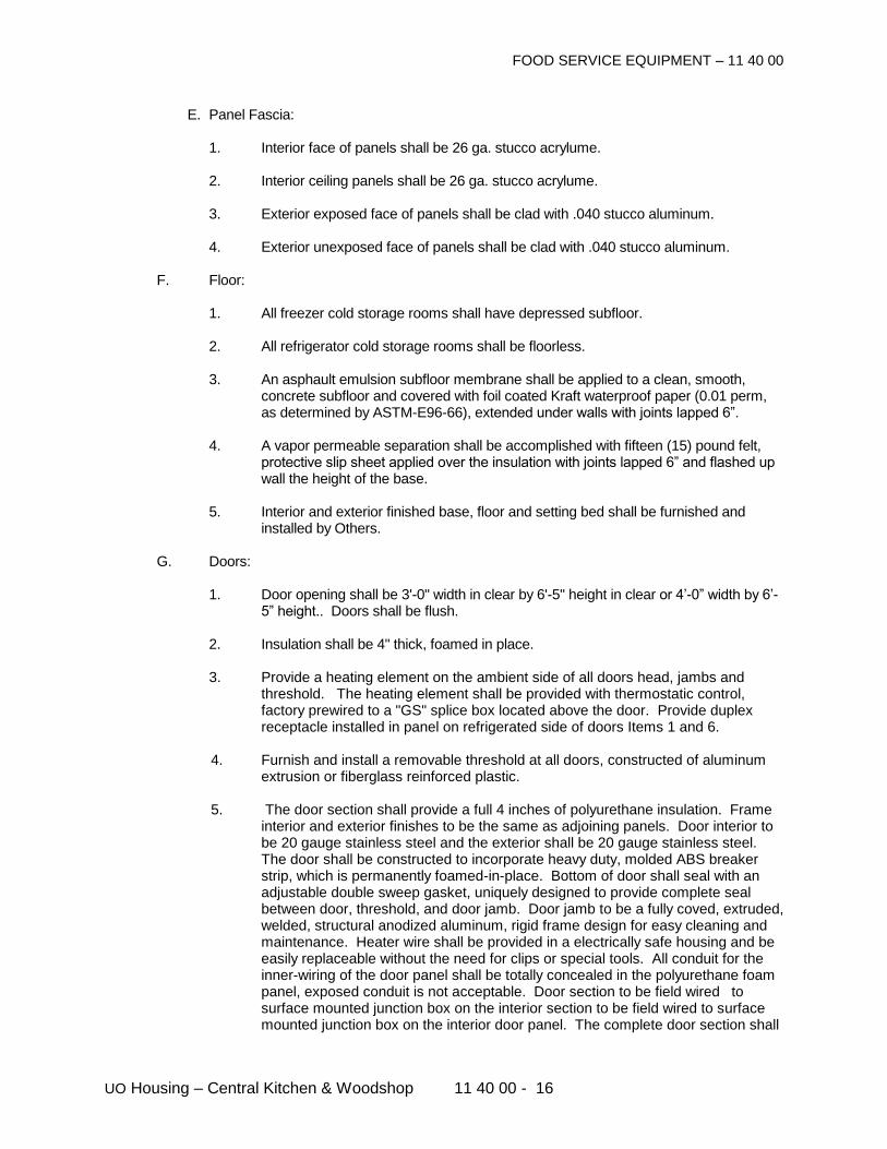
FOOD SERVICE EQUIPMENT – 11 40 00
UO Housing – Central Kitchen & Woodshop 11 40 00 - 16
E. Panel Fascia:
1. Interior face of panels shall be 26 ga. stucco acrylume.
2. Interior ceiling panels shall be 26 ga. stucco acrylume.
3. Exterior exposed face of panels shall be clad with .040 stucco aluminum.
4. Exterior unexposed face of panels shall be clad with .040 stucco aluminum. F. Floor:
1. All freezer cold storage rooms shall have depressed subfloor. 2. All refrigerator cold storage rooms shall be floorless.
3. An asphault emulsion subfloor membrane shall be applied to a clean, smooth,
concrete subfloor and covered with foil coated Kraft waterproof paper (0.01 perm, as determined by ASTM-E96-66), extended under walls with joints lapped 6”.
4. A vapor permeable separation shall be accomplished with fifteen (15) pound felt,
protective slip sheet applied over the insulation with joints lapped 6” and flashed up wall the height of the base.
5. Interior and exterior finished base, floor and setting bed shall be furnished and
installed by Others. G. Doors:
1. Door opening shall be 3'-0" width in clear by 6'-5" height in clear or 4’-0” width by 6’-5” height.. Doors shall be flush.
2. Insulation shall be 4" thick, foamed in place.
3. Provide a heating element on the ambient side of all doors head, jambs and
threshold. The heating element shall be provided with thermostatic control, factory prewired to a "GS" splice box located above the door. Provide duplex receptacle installed in panel on refrigerated side of doors Items 1 and 6.
4. Furnish and install a removable threshold at all doors, constructed of aluminum
extrusion or fiberglass reinforced plastic.
5. The door section shall provide a full 4 inches of polyurethane insulation. Frame interior and exterior finishes to be the same as adjoining panels. Door interior to be 20 gauge stainless steel and the exterior shall be 20 gauge stainless steel. The door shall be constructed to incorporate heavy duty, molded ABS breaker strip, which is permanently foamed-in-place. Bottom of door shall seal with an adjustable double sweep gasket, uniquely designed to provide complete seal between door, threshold, and door jamb. Door jamb to be a fully coved, extruded, welded, structural anodized aluminum, rigid frame design for easy cleaning and maintenance. Heater wire shall be provided in a electrically safe housing and be easily replaceable without the need for clips or special tools. All conduit for the inner-wiring of the door panel shall be totally concealed in the polyurethane foam panel, exposed conduit is not acceptable. Door section to be field wired to surface mounted junction box on the interior section to be field wired to surface mounted junction box on the interior door panel. The complete door section shall
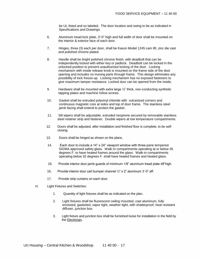
FOOD SERVICE EQUIPMENT – 11 40 00
UO Housing – Central Kitchen & Woodshop 11 40 00 - 17
be UL listed and so labeled. The door location and swing to be as indicated in Specifications and Drawings.
6. Aluminum tread kick plate, 3'-0" high and full width of door shall be mounted on
the interior & exterior face of each door.
7. Hinges, three (3) each per door, shall be Kason Model 1245 cam lift, zinc die cast and polished chrome plated.
8. Handle shall be bright polished chrome finish, with deadbolt that can be
independently locked with either key or padlock. Deadbolt can be locked in the unlocked position to prevent unauthorized locking of the door. Locking mechanism with inside release knob is mounted on the frame side of the door opening and includes no moving parts through frame. This design eliminates any possibility of lock freeze-up. Locking mechanism has no exposed fasteners to give maximum tamper resistance. Locked door can be opened from the inside.
9. Hardware shall be mounted with extra large ½” thick, non-conducting synthetic
tapping plates and machine hi/low screws.
10. Gasket shall be extruded polyvinyl chloride with vulcanized corners and continuous magnetic core at sides and top of door frame. The stainless steel jamb facing shall extend to protect the gasket.
11. Sill wipers shall be adjustable, extruded neoprene secured by removable stainless
steel retainer strip and fastener. Double wipers at low temperature compartments.
12. Doors shall be adjusted, after installation and finished floor is complete, to be self-closing.
13. Doors shall be hinged as shown on the plans.
14. Each door to include a 14” x 24” viewport window with three-pane tempered
SIGMA approved safety glass. Walk-in compartments operating at or below 35 degrees F. to have heated frames around the glass. Walk-in compartments operating below 32 degrees F. shall have heated frames and heated glass.
15. Provide interior door jamb guards of minimum 1/8” aluminum tread plate 48”high.
16. Provide interior door cart bumper channel ¼” x 2” aluminum 3’-0” aff. 17. Provide strip curtains on each door. H. Light Fixtures and Switches:
1. Quantity of light fixtures shall be as indicated on the plan.
2. Light fixtures shall be fluorescent ceiling mounted, cast aluminum, fully enclosed, gasketed, vapor tight, weather tight, with shatterproof, heat resistant diffuser, junction box.
3. Light fixture and junction box shall be furnished loose for installation in the field by
the Electrician.
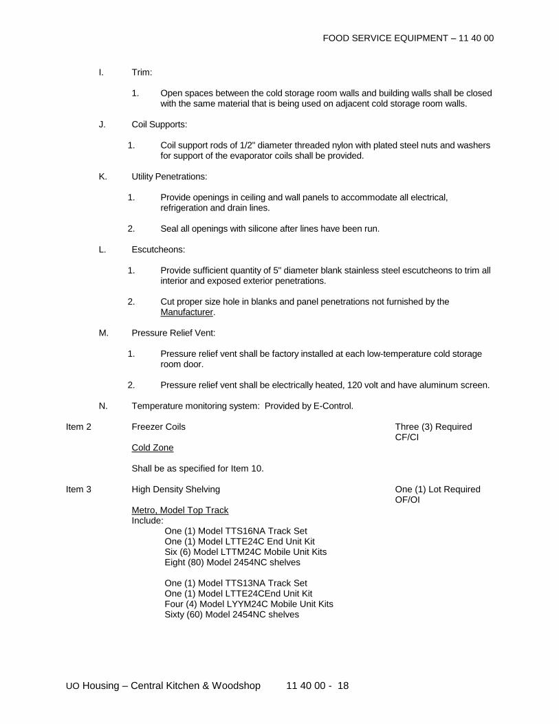
FOOD SERVICE EQUIPMENT – 11 40 00
UO Housing – Central Kitchen & Woodshop 11 40 00 - 18
I. Trim:
1. Open spaces between the cold storage room walls and building walls shall be closed with the same material that is being used on adjacent cold storage room walls.
J. Coil Supports:
1. Coil support rods of 1/2" diameter threaded nylon with plated steel nuts and washers for support of the evaporator coils shall be provided.
K. Utility Penetrations:
1. Provide openings in ceiling and wall panels to accommodate all electrical, refrigeration and drain lines.
2. Seal all openings with silicone after lines have been run.
L. Escutcheons:
1. Provide sufficient quantity of 5" diameter blank stainless steel escutcheons to trim all interior and exposed exterior penetrations.
2. Cut proper size hole in blanks and panel penetrations not furnished by the
Manufacturer. M. Pressure Relief Vent:
1. Pressure relief vent shall be factory installed at each low-temperature cold storage room door.
2. Pressure relief vent shall be electrically heated, 120 volt and have aluminum screen.
N. Temperature monitoring system: Provided by E-Control. Item 2 Freezer Coils Three (3) Required CF/CI Cold Zone Shall be as specified for Item 10. Item 3 High Density Shelving One (1) Lot Required OF/OI Metro, Model Top Track Include: One (1) Model TTS16NA Track Set One (1) Model LTTE24C End Unit Kit Six (6) Model LTTM24C Mobile Unit Kits Eight (80) Model 2454NC shelves One (1) Model TTS13NA Track Set One (1) Model LTTE24CEnd Unit Kit Four (4) Model LYYM24C Mobile Unit Kits Sixty (60) Model 2454NC shelves
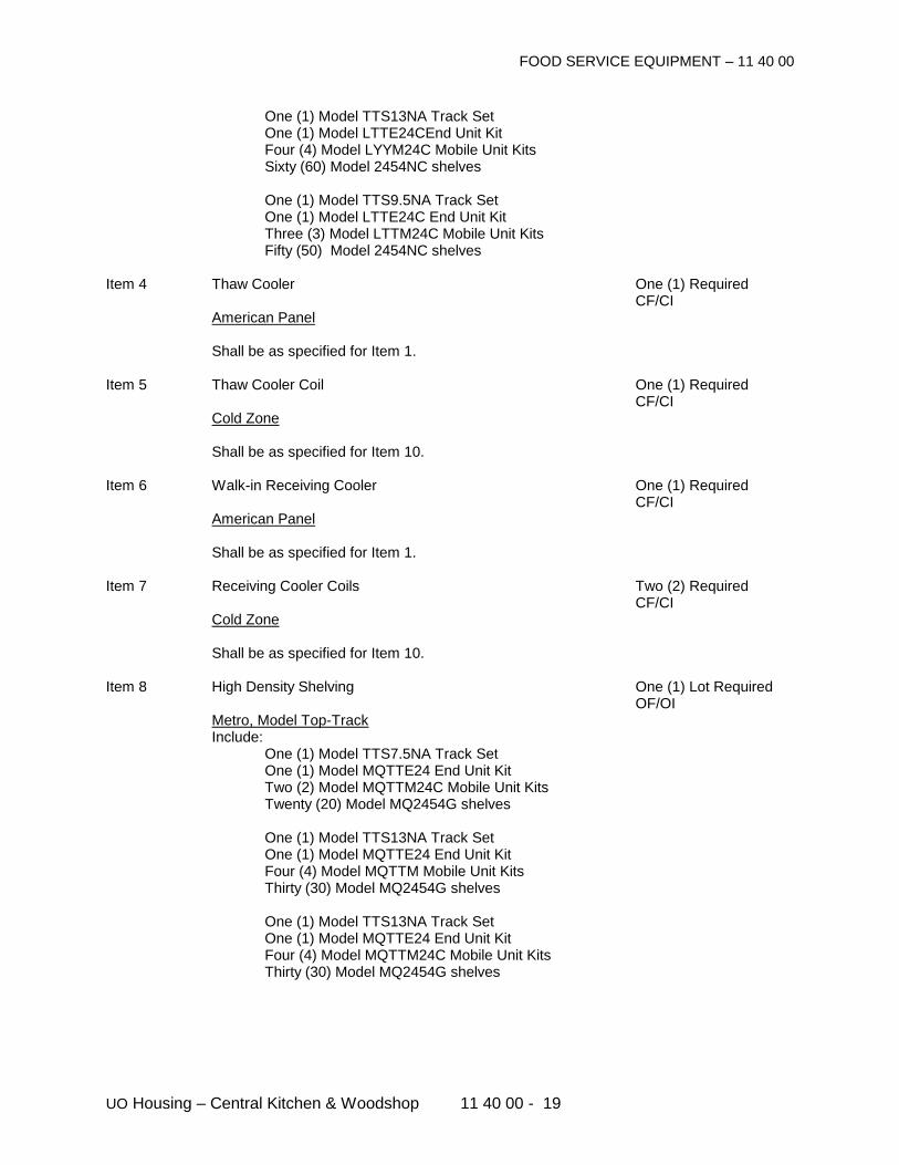
FOOD SERVICE EQUIPMENT – 11 40 00
UO Housing – Central Kitchen & Woodshop 11 40 00 - 19
One (1) Model TTS13NA Track Set One (1) Model LTTE24CEnd Unit Kit Four (4) Model LYYM24C Mobile Unit Kits Sixty (60) Model 2454NC shelves One (1) Model TTS9.5NA Track Set One (1) Model LTTE24C End Unit Kit Three (3) Model LTTM24C Mobile Unit Kits Fifty (50) Model 2454NC shelves Item 4 Thaw Cooler One (1) Required CF/CI American Panel Shall be as specified for Item 1. Item 5 Thaw Cooler Coil One (1) Required CF/CI Cold Zone Shall be as specified for Item 10. Item 6 Walk-in Receiving Cooler One (1) Required CF/CI American Panel Shall be as specified for Item 1. Item 7 Receiving Cooler Coils Two (2) Required CF/CI Cold Zone Shall be as specified for Item 10. Item 8 High Density Shelving One (1) Lot Required OF/OI Metro, Model Top-Track Include: One (1) Model TTS7.5NA Track Set One (1) Model MQTTE24 End Unit Kit Two (2) Model MQTTM24C Mobile Unit Kits Twenty (20) Model MQ2454G shelves One (1) Model TTS13NA Track Set
One (1) Model MQTTE24 End Unit Kit Four (4) Model MQTTM Mobile Unit Kits Thirty (30) Model MQ2454G shelves One (1) Model TTS13NA Track Set One (1) Model MQTTE24 End Unit Kit Four (4) Model MQTTM24C Mobile Unit Kits Thirty (30) Model MQ2454G shelves
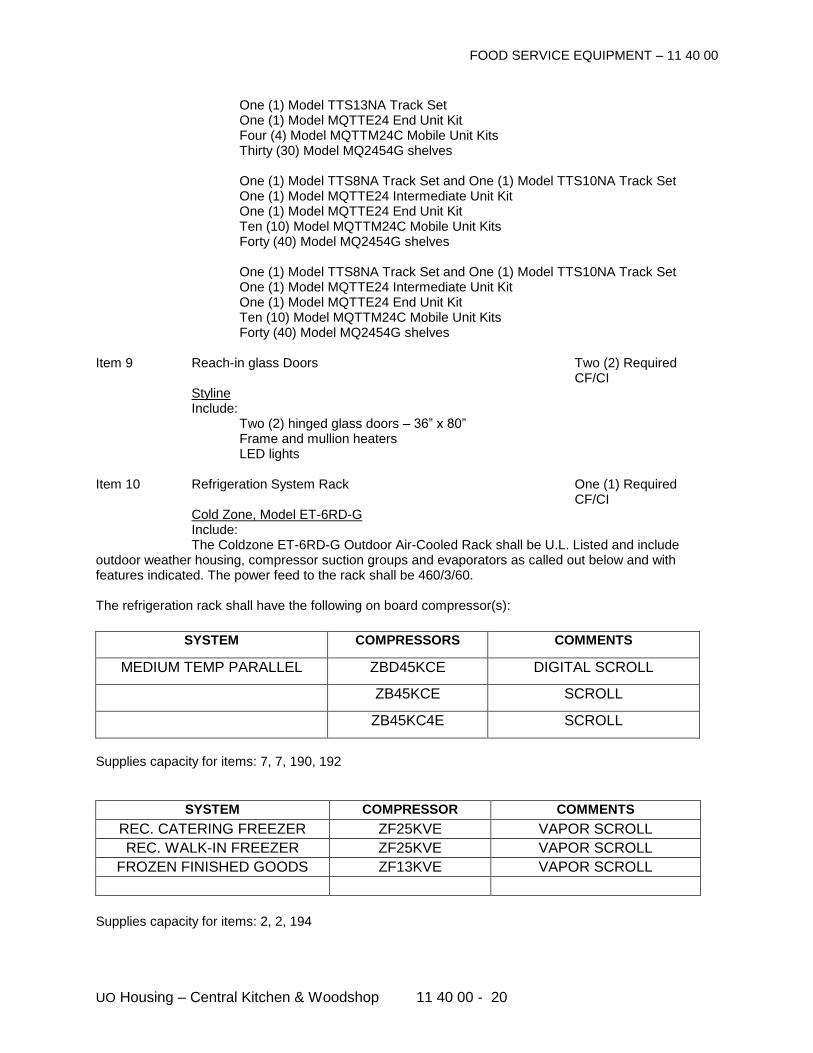
FOOD SERVICE EQUIPMENT – 11 40 00
UO Housing – Central Kitchen & Woodshop 11 40 00 - 20
One (1) Model TTS13NA Track Set One (1) Model MQTTE24 End Unit Kit Four (4) Model MQTTM24C Mobile Unit Kits Thirty (30) Model MQ2454G shelves One (1) Model TTS8NA Track Set and One (1) Model TTS10NA Track Set One (1) Model MQTTE24 Intermediate Unit Kit One (1) Model MQTTE24 End Unit Kit Ten (10) Model MQTTM24C Mobile Unit Kits Forty (40) Model MQ2454G shelves One (1) Model TTS8NA Track Set and One (1) Model TTS10NA Track Set One (1) Model MQTTE24 Intermediate Unit Kit One (1) Model MQTTE24 End Unit Kit Ten (10) Model MQTTM24C Mobile Unit Kits Forty (40) Model MQ2454G shelves
Item 9 Reach-in glass Doors Two (2) Required CF/CI Styline Include: Two (2) hinged glass doors – 36” x 80” Frame and mullion heaters LED lights Item 10 Refrigeration System Rack One (1) Required CF/CI Cold Zone, Model ET-6RD-G Include: The Coldzone ET-6RD-G Outdoor Air-Cooled Rack shall be U.L. Listed and include outdoor weather housing, compressor suction groups and evaporators as called out below and with features indicated. The power feed to the rack shall be 460/3/60. The refrigeration rack shall have the following on board compressor(s):
SYSTEM COMPRESSORS COMMENTS
MEDIUM TEMP PARALLEL ZBD45KCE DIGITAL SCROLL
ZB45KCE SCROLL
ZB45KC4E SCROLL
Supplies capacity for items: 7, 7, 190, 192
SYSTEM COMPRESSOR COMMENTS REC. CATERING FREEZER ZF25KVE VAPOR SCROLL
REC. WALK-IN FREEZER ZF25KVE VAPOR SCROLL
FROZEN FINISHED GOODS FR.
ZF13KVE VAPOR SCROLL
Supplies capacity for items: 2, 2, 194
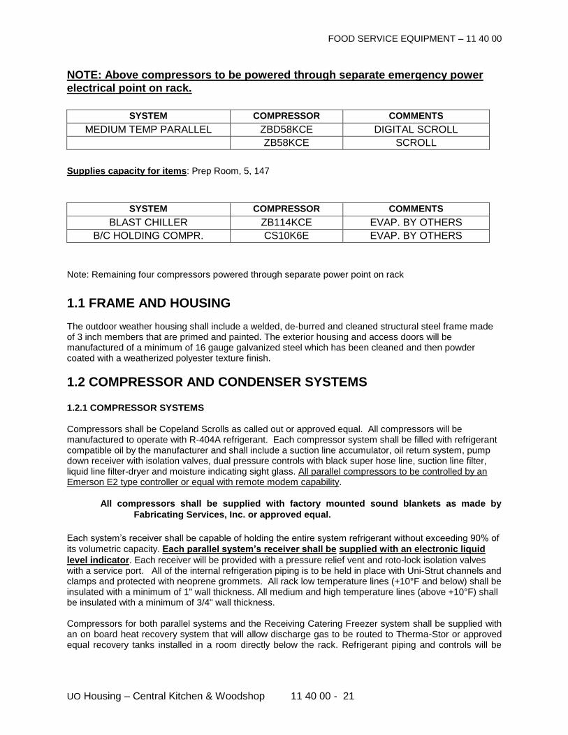
FOOD SERVICE EQUIPMENT – 11 40 00
UO Housing – Central Kitchen & Woodshop 11 40 00 - 21
NOTE: Above compressors to be powered through separate emergency power electrical point on rack.
SYSTEM COMPRESSOR COMMENTS MEDIUM TEMP PARALLEL ZBD58KCE DIGITAL SCROLL
ZB58KCE SCROLL
Supplies capacity for items: Prep Room, 5, 147
SYSTEM COMPRESSOR COMMENTS
BLAST CHILLER ZB114KCE EVAP. BY OTHERS
B/C HOLDING COMPR. CS10K6E EVAP. BY OTHERS
Note: Remaining four compressors powered through separate power point on rack
1.1 FRAME AND HOUSING
The outdoor weather housing shall include a welded, de-burred and cleaned structural steel frame made of 3 inch members that are primed and painted. The exterior housing and access doors will be manufactured of a minimum of 16 gauge galvanized steel which has been cleaned and then powder coated with a weatherized polyester texture finish.
1.2 COMPRESSOR AND CONDENSER SYSTEMS
1.2.1 COMPRESSOR SYSTEMS Compressors shall be Copeland Scrolls as called out or approved equal. All compressors will be manufactured to operate with R-404A refrigerant. Each compressor system shall be filled with refrigerant compatible oil by the manufacturer and shall include a suction line accumulator, oil return system, pump down receiver with isolation valves, dual pressure controls with black super hose line, suction line filter, liquid line filter-dryer and moisture indicating sight glass. All parallel compressors to be controlled by an Emerson E2 type controller or equal with remote modem capability.
All compressors shall be supplied with factory mounted sound blankets as made by Fabricating Services, Inc. or approved equal.
Each system’s receiver shall be capable of holding the entire system refrigerant without exceeding 90% of
its volumetric capacity. Each parallel system’s receiver shall be supplied with an electronic liquid level indicator. Each receiver will be provided with a pressure relief vent and roto-lock isolation valves with a service port. All of the internal refrigeration piping is to be held in place with Uni-Strut channels and clamps and protected with neoprene grommets. All rack low temperature lines (+10°F and below) shall be insulated with a minimum of 1" wall thickness. All medium and high temperature lines (above +10°F) shall be insulated with a minimum of 3/4" wall thickness. Compressors for both parallel systems and the Receiving Catering Freezer system shall be supplied with an on board heat recovery system that will allow discharge gas to be routed to Therma-Stor or approved equal recovery tanks installed in a room directly below the rack. Refrigerant piping and controls will be
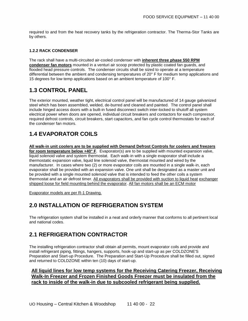
FOOD SERVICE EQUIPMENT – 11 40 00
UO Housing – Central Kitchen & Woodshop 11 40 00 - 22
required to and from the heat recovery tanks by the refrigeration contractor. The Therma-Stor Tanks are by others.
1.2.2 RACK CONDENSER
The rack shall have a multi-circuited air-cooled condenser with inherent three phase 550 RPM
condenser fan motors mounted in a venturi air scoop protected by plastic coated fan guards, and flooded head pressure controls. The condenser circuits shall be sized to operate at a temperature differential between the ambient and condensing temperatures of 20° F for medium temp applications and 15 degrees for low temp applications based on an ambient temperature of 100° F.
1.3 CONTROL PANEL The exterior mounted, weather tight, electrical control panel will be manufactured of 14 gauge galvanized steel which has been assembled, welded, de-burred and cleaned and painted. The control panel shall include hinged access doors with a built-in fused disconnect switch inter-locked to shutoff all system electrical power when doors are opened, individual circuit breakers and contactors for each compressor, required defrost controls, circuit breakers, start capacitors, and fan cycle control thermostats for each of the condenser fan motors.
1.4 EVAPORATOR COILS All walk-in unit coolers are to be supplied with Demand Defrost Controls for coolers and freezers for room temperature below +40° F. Evaporator(s) are to be supplied with mounted expansion valve, liquid solenoid valve and system thermostat. Each walk-in with a single evaporator shall include a thermostatic expansion valve, liquid line solenoid valve, thermostat mounted and wired by the manufacturer. In cases where two (2) or more evaporator coils are mounted in a single walk-in, each evaporator shall be provided with an expansion valve. One unit shall be designated as a master unit and be provided with a single mounted solenoid valve that is intended to feed the other coils a system thermostat and an air defrost timer. All evaporators shall be provided with suction to liquid heat exchanger shipped loose for field mounting behind the evaporator. All fan motors shall be an ECM motor Evaporator models are per R-1 Drawing. 2.0 INSTALLATION OF REFRIGERATION SYSTEM The refrigeration system shall be installed in a neat and orderly manner that conforms to all pertinent local and national codes.
2.1 REFRIGERATION CONTRACTOR The installing refrigeration contractor shall obtain all permits, mount evaporator coils and provide and install refrigerant piping, fittings, hangers, supports, hook-up and start-up as per COLDZONE'S Preparation and Start-up Procedure. The Preparation and Start-Up Procedure shall be filled out, signed and returned to COLDZONE within ten (10) days of start-up.
All liquid lines for low temp systems for the Receiving Catering Freezer, Receiving Walk-In Freezer and Frozen Finished Goods Freezer must be insulated from the rack to inside of the walk-in due to subcooled refrigerant being supplied.
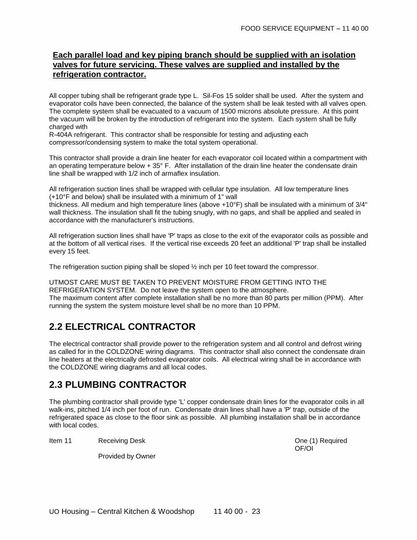
FOOD SERVICE EQUIPMENT – 11 40 00
UO Housing – Central Kitchen & Woodshop 11 40 00 - 23
Each parallel load and key piping branch should be supplied with an isolation valves for future servicing. These valves are supplied and installed by the refrigeration contractor.
All copper tubing shall be refrigerant grade type L. Sil-Fos 15 solder shall be used. After the system and evaporator coils have been connected, the balance of the system shall be leak tested with all valves open. The complete system shall be evacuated to a vacuum of 1500 microns absolute pressure. At this point the vacuum will be broken by the introduction of refrigerant into the system. Each system shall be fully charged with R-404A refrigerant. This contractor shall be responsible for testing and adjusting each compressor/condensing system to make the total system operational. This contractor shall provide a drain line heater for each evaporator coil located within a compartment with an operating temperature below + 35° F. After installation of the drain line heater the condensate drain line shall be wrapped with 1/2 inch of armaflex insulation. All refrigeration suction lines shall be wrapped with cellular type insulation. All low temperature lines (+10°F and below) shall be insulated with a minimum of 1" wall thickness. All medium and high temperature lines (above +10°F) shall be insulated with a minimum of 3/4" wall thickness. The insulation shall fit the tubing snugly, with no gaps, and shall be applied and sealed in accordance with the manufacturer's instructions. All refrigeration suction lines shall have 'P' traps as close to the exit of the evaporator coils as possible and at the bottom of all vertical rises. If the vertical rise exceeds 20 feet an additional 'P' trap shall be installed every 15 feet. The refrigeration suction piping shall be sloped ½ inch per 10 feet toward the compressor. UTMOST CARE MUST BE TAKEN TO PREVENT MOISTURE FROM GETTING INTO THE REFRIGERATION SYSTEM. Do not leave the system open to the atmosphere. The maximum content after complete installation shall be no more than 80 parts per million (PPM). After running the system the system moisture level shall be no more than 10 PPM.
2.2 ELECTRICAL CONTRACTOR
The electrical contractor shall provide power to the refrigeration system and all control and defrost wiring as called for in the COLDZONE wiring diagrams. This contractor shall also connect the condensate drain line heaters at the electrically defrosted evaporator coils. All electrical wiring shall be in accordance with the COLDZONE wiring diagrams and all local codes.
2.3 PLUMBING CONTRACTOR The plumbing contractor shall provide type 'L' copper condensate drain lines for the evaporator coils in all walk-ins, pitched 1/4 inch per foot of run. Condensate drain lines shall have a 'P' trap, outside of the refrigerated space as close to the floor sink as possible. All plumbing installation shall be in accordance with local codes. Item 11 Receiving Desk One (1) Required OF/OI Provided by Owner
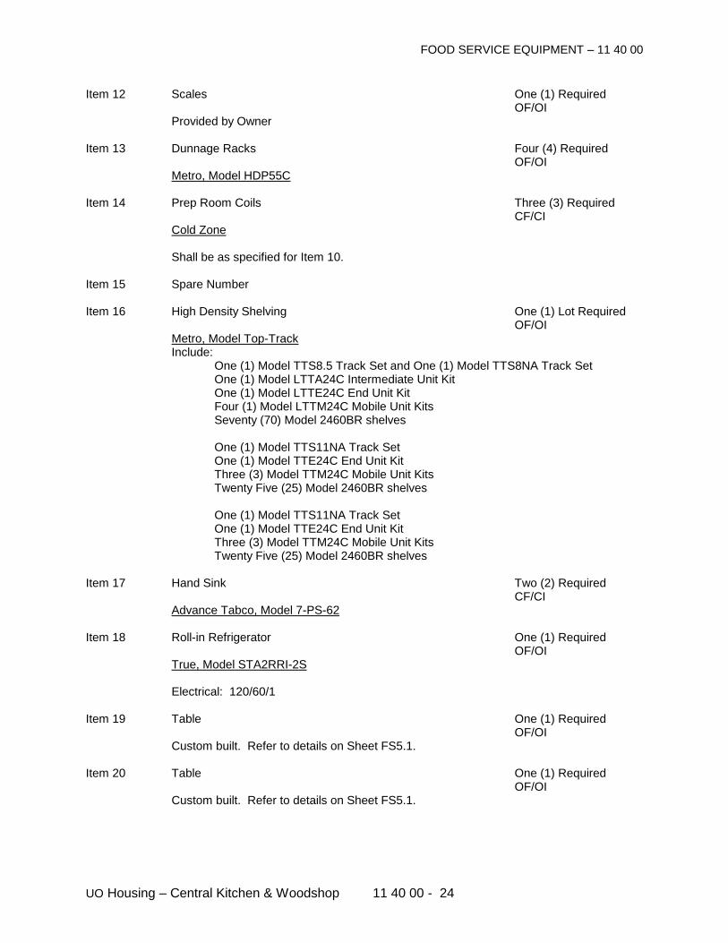
FOOD SERVICE EQUIPMENT – 11 40 00
UO Housing – Central Kitchen & Woodshop 11 40 00 - 24
Item 12 Scales One (1) Required OF/OI Provided by Owner Item 13 Dunnage Racks Four (4) Required OF/OI Metro, Model HDP55C Item 14 Prep Room Coils Three (3) Required CF/CI Cold Zone Shall be as specified for Item 10. Item 15 Spare Number Item 16 High Density Shelving One (1) Lot Required OF/OI Metro, Model Top-Track Include: One (1) Model TTS8.5 Track Set and One (1) Model TTS8NA Track Set One (1) Model LTTA24C Intermediate Unit Kit One (1) Model LTTE24C End Unit Kit Four (1) Model LTTM24C Mobile Unit Kits Seventy (70) Model 2460BR shelves One (1) Model TTS11NA Track Set One (1) Model TTE24C End Unit Kit Three (3) Model TTM24C Mobile Unit Kits Twenty Five (25) Model 2460BR shelves One (1) Model TTS11NA Track Set One (1) Model TTE24C End Unit Kit Three (3) Model TTM24C Mobile Unit Kits Twenty Five (25) Model 2460BR shelves Item 17 Hand Sink Two (2) Required CF/CI Advance Tabco, Model 7-PS-62 Item 18 Roll-in Refrigerator One (1) Required OF/OI True, Model STA2RRI-2S Electrical: 120/60/1 Item 19 Table One (1) Required OF/OI Custom built. Refer to details on Sheet FS5.1. Item 20 Table One (1) Required OF/OI Custom built. Refer to details on Sheet FS5.1.
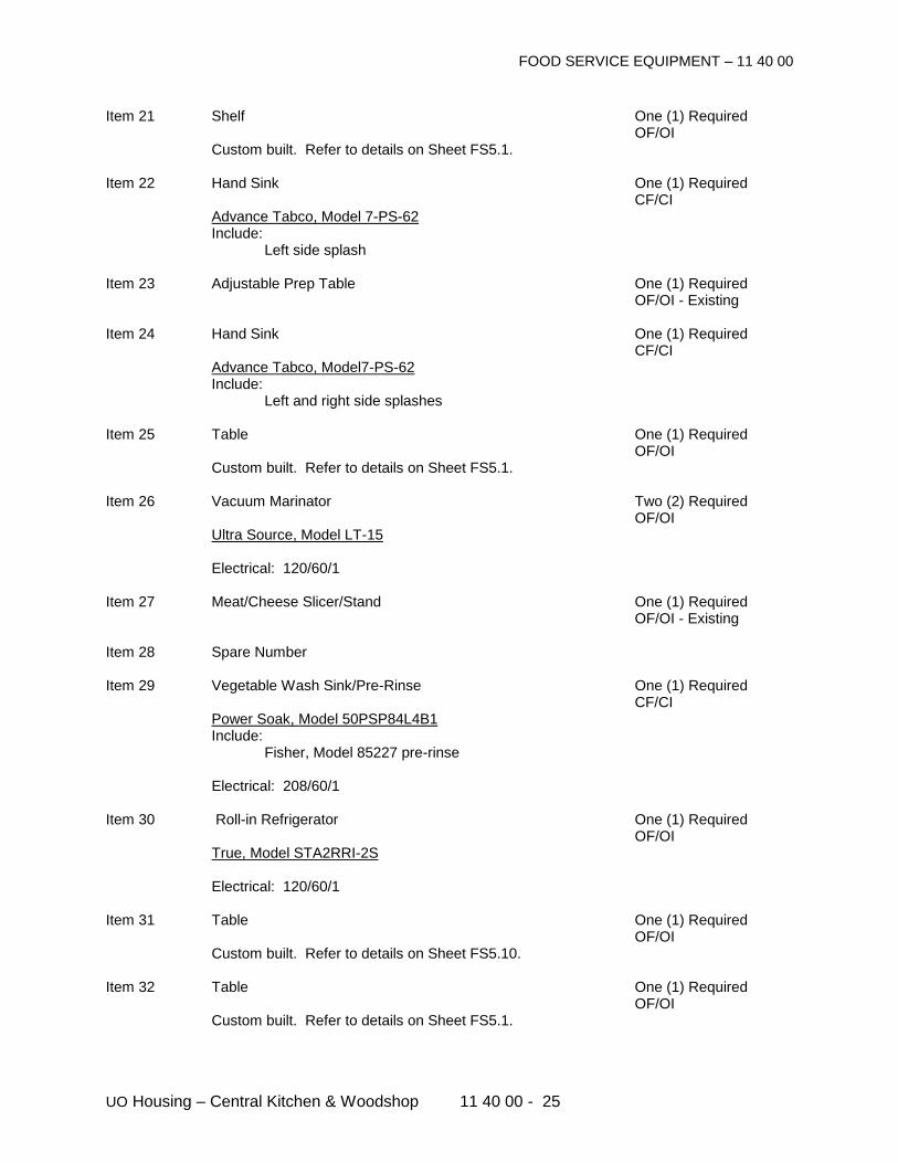
FOOD SERVICE EQUIPMENT – 11 40 00
UO Housing – Central Kitchen & Woodshop 11 40 00 - 25
Item 21 Shelf One (1) Required OF/OI Custom built. Refer to details on Sheet FS5.1. Item 22 Hand Sink One (1) Required CF/CI Advance Tabco, Model 7-PS-62 Include: Left side splash Item 23 Adjustable Prep Table One (1) Required OF/OI - Existing Item 24 Hand Sink One (1) Required CF/CI Advance Tabco, Model7-PS-62 Include: Left and right side splashes Item 25 Table One (1) Required OF/OI Custom built. Refer to details on Sheet FS5.1. Item 26 Vacuum Marinator Two (2) Required OF/OI Ultra Source, Model LT-15 Electrical: 120/60/1 Item 27 Meat/Cheese Slicer/Stand One (1) Required OF/OI - Existing Item 28 Spare Number Item 29 Vegetable Wash Sink/Pre-Rinse One (1) Required CF/CI Power Soak, Model 50PSP84L4B1 Include: Fisher, Model 85227 pre-rinse Electrical: 208/60/1 Item 30 Roll-in Refrigerator One (1) Required OF/OI True, Model STA2RRI-2S Electrical: 120/60/1 Item 31 Table One (1) Required OF/OI Custom built. Refer to details on Sheet FS5.10. Item 32 Table One (1) Required OF/OI Custom built. Refer to details on Sheet FS5.1.
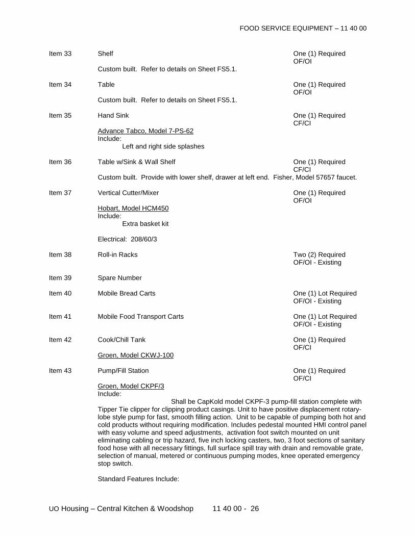
FOOD SERVICE EQUIPMENT – 11 40 00
UO Housing – Central Kitchen & Woodshop 11 40 00 - 26
Item 33 Shelf One (1) Required OF/OI Custom built. Refer to details on Sheet FS5.1. Item 34 Table One (1) Required OF/OI Custom built. Refer to details on Sheet FS5.1. Item 35 Hand Sink One (1) Required CF/CI Advance Tabco, Model 7-PS-62 Include: Left and right side splashes Item 36 Table w/Sink & Wall Shelf One (1) Required CF/CI Custom built. Provide with lower shelf, drawer at left end. Fisher, Model 57657 faucet. Item 37 Vertical Cutter/Mixer One (1) Required OF/OI Hobart, Model HCM450 Include: Extra basket kit Electrical: 208/60/3 Item 38 Roll-in Racks Two (2) Required OF/OI - Existing Item 39 Spare Number Item 40 Mobile Bread Carts One (1) Lot Required OF/OI - Existing Item 41 Mobile Food Transport Carts One (1) Lot Required OF/OI - Existing Item 42 Cook/Chill Tank One (1) Required OF/CI Groen, Model CKWJ-100 Item 43 Pump/Fill Station One (1) Required OF/CI Groen, Model CKPF/3 Include:
Shall be CapKold model CKPF-3 pump-fill station complete with Tipper Tie clipper for clipping product casings. Unit to have positive displacement rotary-lobe style pump for fast, smooth filling action. Unit to be capable of pumping both hot and cold products without requiring modification. Includes pedestal mounted HMI control panel with easy volume and speed adjustments, activation foot switch mounted on unit eliminating cabling or trip hazard, five inch locking casters, two, 3 foot sections of sanitary food hose with all necessary fittings, full surface spill tray with drain and removable grate, selection of manual, metered or continuous pumping modes, knee operated emergency stop switch.
Standard Features Include:
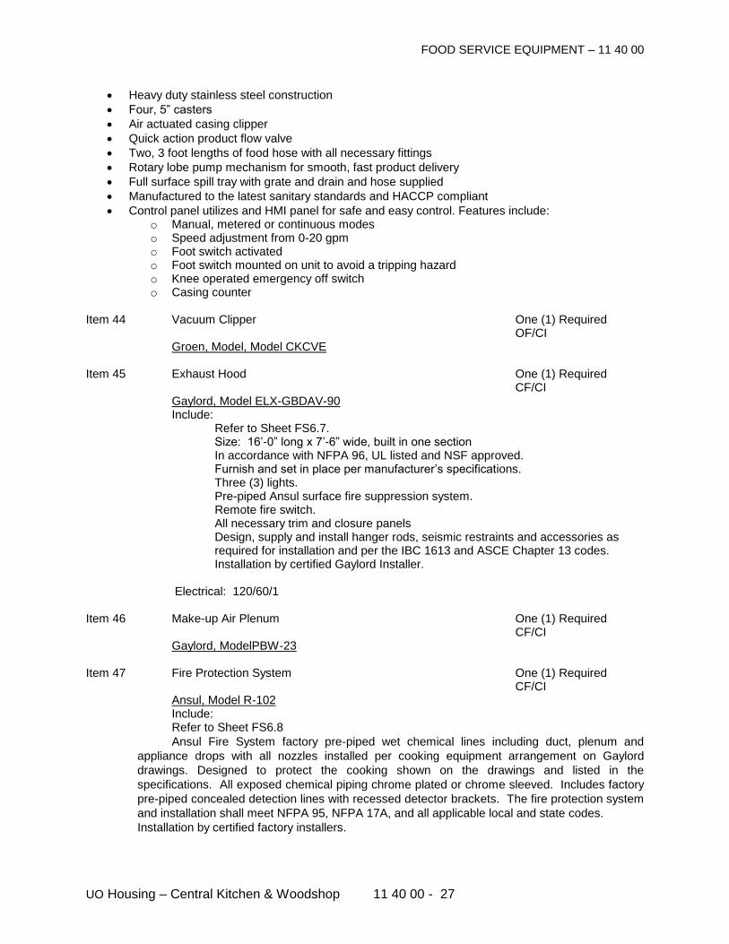
FOOD SERVICE EQUIPMENT – 11 40 00
UO Housing – Central Kitchen & Woodshop 11 40 00 - 27
Heavy duty stainless steel construction
Four, 5” casters
Air actuated casing clipper
Quick action product flow valve
Two, 3 foot lengths of food hose with all necessary fittings
Rotary lobe pump mechanism for smooth, fast product delivery
Full surface spill tray with grate and drain and hose supplied
Manufactured to the latest sanitary standards and HACCP compliant
Control panel utilizes and HMI panel for safe and easy control. Features include: o Manual, metered or continuous modes o Speed adjustment from 0-20 gpm o Foot switch activated o Foot switch mounted on unit to avoid a tripping hazard o Knee operated emergency off switch o Casing counter
Item 44 Vacuum Clipper One (1) Required OF/CI Groen, Model, Model CKCVE Item 45 Exhaust Hood One (1) Required CF/CI Gaylord, Model ELX-GBDAV-90 Include: Refer to Sheet FS6.7. Size: 16’-0” long x 7’-6” wide, built in one section In accordance with NFPA 96, UL listed and NSF approved. Furnish and set in place per manufacturer’s specifications. Three (3) lights. Pre-piped Ansul surface fire suppression system. Remote fire switch. All necessary trim and closure panels
Design, supply and install hanger rods, seismic restraints and accessories as required for installation and per the IBC 1613 and ASCE Chapter 13 codes. Installation by certified Gaylord Installer.
Electrical: 120/60/1 Item 46 Make-up Air Plenum One (1) Required CF/CI Gaylord, ModelPBW-23 Item 47 Fire Protection System One (1) Required CF/CI Ansul, Model R-102 Include: Refer to Sheet FS6.8
Ansul Fire System factory pre-piped wet chemical lines including duct, plenum and
appliance drops with all nozzles installed per cooking equipment arrangement on Gaylord
drawings. Designed to protect the cooking shown on the drawings and listed in the
specifications. All exposed chemical piping chrome plated or chrome sleeved. Includes factory
pre-piped concealed detection lines with recessed detector brackets. The fire protection system
and installation shall meet NFPA 95, NFPA 17A, and all applicable local and state codes.
Installation by certified factory installers.
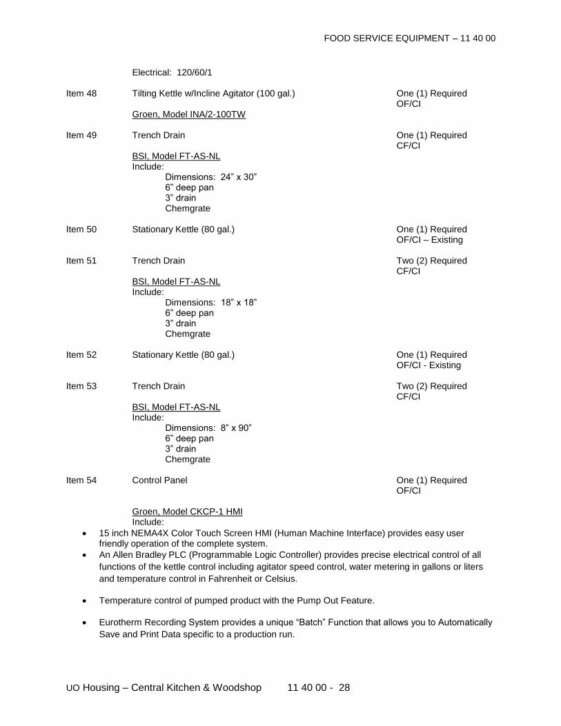
FOOD SERVICE EQUIPMENT – 11 40 00
UO Housing – Central Kitchen & Woodshop 11 40 00 - 28
Electrical: 120/60/1 Item 48 Tilting Kettle w/Incline Agitator (100 gal.) One (1) Required OF/CI Groen, Model INA/2-100TW Item 49 Trench Drain One (1) Required CF/CI BSI, Model FT-AS-NL Include: Dimensions: 24” x 30” 6” deep pan 3” drain Chemgrate Item 50 Stationary Kettle (80 gal.) One (1) Required OF/CI – Existing Item 51 Trench Drain Two (2) Required CF/CI BSI, Model FT-AS-NL Include: Dimensions: 18” x 18” 6” deep pan 3” drain Chemgrate Item 52 Stationary Kettle (80 gal.) One (1) Required OF/CI - Existing Item 53 Trench Drain Two (2) Required CF/CI BSI, Model FT-AS-NL Include: Dimensions: 8” x 90” 6” deep pan 3” drain Chemgrate Item 54 Control Panel One (1) Required OF/CI Groen, Model CKCP-1 HMI Include:
15 inch NEMA4X Color Touch Screen HMI (Human Machine Interface) provides easy user friendly operation of the complete system.
An Allen Bradley PLC (Programmable Logic Controller) provides precise electrical control of all
functions of the kettle control including agitator speed control, water metering in gallons or liters
and temperature control in Fahrenheit or Celsius.
Temperature control of pumped product with the Pump Out Feature.
Eurotherm Recording System provides a unique “Batch” Function that allows you to Automatically
Save and Print Data specific to a production run.
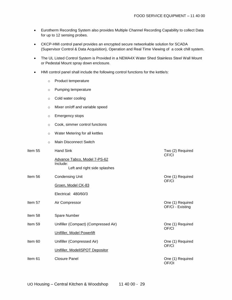
FOOD SERVICE EQUIPMENT – 11 40 00
UO Housing – Central Kitchen & Woodshop 11 40 00 - 29
Eurotherm Recording System also provides Multiple Channel Recording Capability to collect Data
for up to 12 sensing probes.
CKCP-HMI control panel provides an encrypted secure networkable solution for SCADA
(Supervisor Control & Data Acquisition), Operation and Real Time Viewing of a cook chill system.
The UL Listed Control System is Provided in a NEMA4X Water Shed Stainless Steel Wall Mount
or Pedestal Mount spray down enclosure.
HMI control panel shall include the following control functions for the kettle/s:
o Product temperature
o Pumping temperature
o Cold water cooling
o Mixer on/off and variable speed
o Emergency stops
o Cook, simmer control functions
o Water Metering for all kettles
o Main Disconnect Switch
Item 55 Hand Sink Two (2) Required CF/CI Advance Tabco, Model 7-PS-62 Include: Left and right side splashes Item 56 Condensing Unit One (1) Required OF/CI Groen, Model CK-83 Electrical: 480/60/3 Item 57 Air Compressor One (1) Required OF/CI - Existing Item 58 Spare Number Item 59 Unifiller (Compact) (Compressed Air) One (1) Required OF/CI Unifiller, Model Powerlift Item 60 Unifiller (Compressed Air) One (1) Required OF/CI Unifiller, ModelISPOT Depositor Item 61 Closure Panel One (1) Required OF/OI
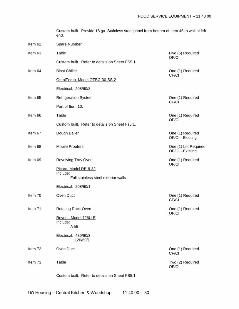
FOOD SERVICE EQUIPMENT – 11 40 00
UO Housing – Central Kitchen & Woodshop 11 40 00 - 30
Custom built. Provide 18 ga. Stainless steel panel from bottom of Item 46 to wall at left end.
Item 62 Spare Number Item 63 Table Five (5) Required OF/OI Custom built. Refer to details on Sheet FS5.1. Item 64 Blast Chiller One (1) Required CF/CI OmniTemp, Model OTBC-30-SS-2 Electrical: 208/60/3 Item 65 Refrigeration System One (1) Required CF/CI Part of Item 10. Item 66 Table One (1) Required OF/OI Custom built. Refer to details on Sheet Fs5.1. Item 67 Dough Baller One (1) Required OF/OI - Existing Item 68 Mobile Proofers One (1) Lot Required OF/OI - Existing Item 69 Revolving Tray Oven One (1) Required OF/CI Picard, Model RE-8-32 Include: Full stainless steel exterior walls Electrical: 208/60/1 Item 70 Oven Duct One (1) Required CF/CI Item 71 Rotating Rack Oven One (1) Required OF/CI Revent, Model 726U-E Include: A-lift Electrical: 480/60/3 120/60/1 Item 72 Oven Duct One (1) Required CF/CI Item 73 Table Two (2) Required OF/OI Custom built. Refer to details on Sheet FS5.1.
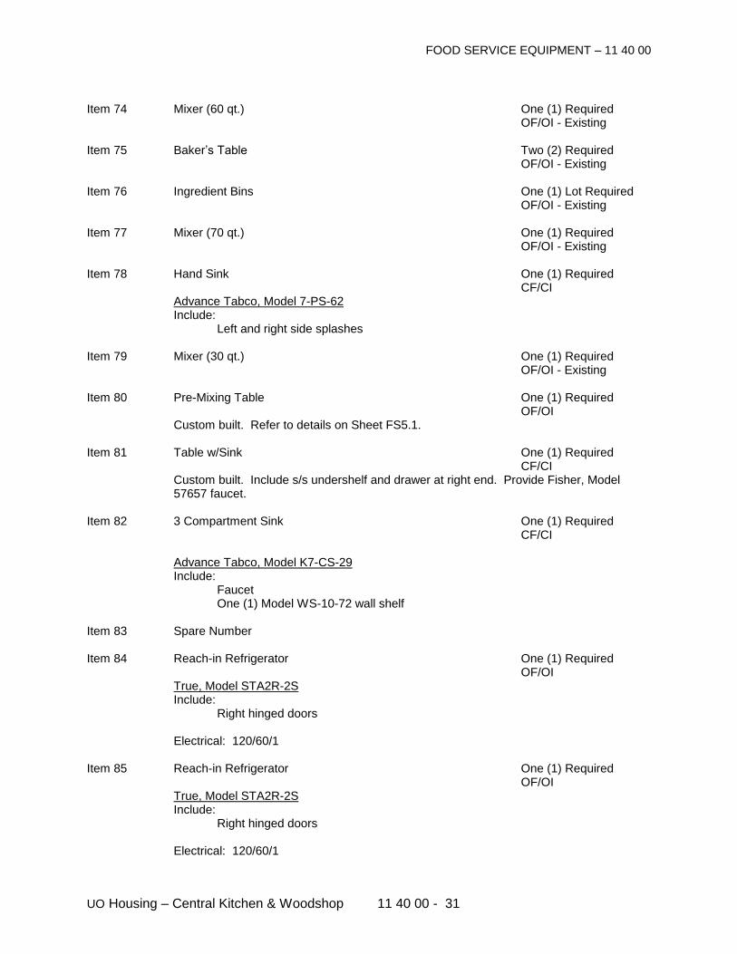
FOOD SERVICE EQUIPMENT – 11 40 00
UO Housing – Central Kitchen & Woodshop 11 40 00 - 31
Item 74 Mixer (60 qt.) One (1) Required OF/OI - Existing Item 75 Baker’s Table Two (2) Required OF/OI - Existing Item 76 Ingredient Bins One (1) Lot Required OF/OI - Existing Item 77 Mixer (70 qt.) One (1) Required OF/OI - Existing Item 78 Hand Sink One (1) Required CF/CI Advance Tabco, Model 7-PS-62 Include: Left and right side splashes Item 79 Mixer (30 qt.) One (1) Required OF/OI - Existing Item 80 Pre-Mixing Table One (1) Required OF/OI Custom built. Refer to details on Sheet FS5.1. Item 81 Table w/Sink One (1) Required CF/CI
Custom built. Include s/s undershelf and drawer at right end. Provide Fisher, Model 57657 faucet.
Item 82 3 Compartment Sink One (1) Required CF/CI Advance Tabco, Model K7-CS-29 Include: Faucet One (1) Model WS-10-72 wall shelf Item 83 Spare Number Item 84 Reach-in Refrigerator One (1) Required OF/OI True, Model STA2R-2S Include: Right hinged doors Electrical: 120/60/1 Item 85 Reach-in Refrigerator One (1) Required OF/OI True, Model STA2R-2S Include: Right hinged doors Electrical: 120/60/1
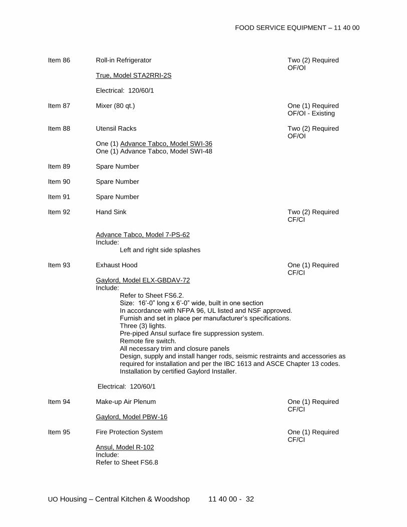
FOOD SERVICE EQUIPMENT – 11 40 00
UO Housing – Central Kitchen & Woodshop 11 40 00 - 32
Item 86 Roll-in Refrigerator Two (2) Required OF/OI True, Model STA2RRI-2S Electrical: 120/60/1 Item 87 Mixer (80 qt.) One (1) Required OF/OI - Existing Item 88 Utensil Racks Two (2) Required OF/OI One (1) Advance Tabco, Model SWI-36 One (1) Advance Tabco, Model SWI-48 Item 89 Spare Number Item 90 Spare Number Item 91 Spare Number Item 92 Hand Sink Two (2) Required CF/CI Advance Tabco, Model 7-PS-62 Include: Left and right side splashes Item 93 Exhaust Hood One (1) Required CF/CI Gaylord, Model ELX-GBDAV-72 Include: Refer to Sheet FS6.2. Size: 16’-0” long x 6’-0” wide, built in one section In accordance with NFPA 96, UL listed and NSF approved. Furnish and set in place per manufacturer’s specifications. Three (3) lights. Pre-piped Ansul surface fire suppression system. Remote fire switch. All necessary trim and closure panels
Design, supply and install hanger rods, seismic restraints and accessories as required for installation and per the IBC 1613 and ASCE Chapter 13 codes. Installation by certified Gaylord Installer.
Electrical: 120/60/1 Item 94 Make-up Air Plenum One (1) Required CF/CI Gaylord, Model PBW-16 Item 95 Fire Protection System One (1) Required CF/CI Ansul, Model R-102 Include: Refer to Sheet FS6.8
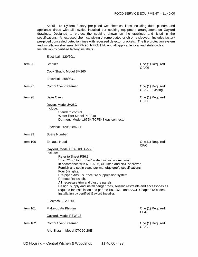
FOOD SERVICE EQUIPMENT – 11 40 00
UO Housing – Central Kitchen & Woodshop 11 40 00 - 33
Ansul Fire System factory pre-piped wet chemical lines including duct, plenum and
appliance drops with all nozzles installed per cooking equipment arrangement on Gaylord
drawings. Designed to protect the cooking shown on the drawings and listed in the
specifications. All exposed chemical piping chrome plated or chrome sleeved. Includes factory
pre-piped concealed detection lines with recessed detector brackets. The fire protection system
and installation shall meet NFPA 95, NFPA 17A, and all applicable local and state codes.
Installation by certified factory installers. Electrical: 120/60/1 Item 96 Smoker One (1) Required OF/OI Cook Shack, Model SM260 Electrical: 208/60/1 Item 97 Combi Oven/Steamer One (1) Required OF/CI - Existing Item 98 Bake Oven One (1) Required OF/CI Doyon, Model JA28G Include: Standard control Water filter Model PLF240 Dormont, Model 1675KITCFS48 gas connector Electrical: 120/208/60/1 Item 99 Spare Number Item 100 Exhaust Hood One (1) Required CF/CI Gaylord, Model ELX-GBDAV-66 Include: Refer to Sheet FS6.3. Size: 21’-0” long x 5’-6” wide, built in two sections. In accordance with NFPA 96, UL listed and NSF approved. Furnish and set in place per manufacturer’s specifications. Four (4) lights. Pre-piped Ansul surface fire suppression system. Remote fire switch. All necessary trim and closure panels
Design, supply and install hanger rods, seismic restraints and accessories as required for installation and per the IBC 1613 and ASCE Chapter 13 codes. Installation by certified Gaylord Installer.
Electrical: 120/60/1 Item 101 Make-up Air Plenum One (1) Required CF/CI Gaylord, Model PBW-18 Item 102 Combi Oven/Steamer One (1) Required OF/CI Alto-Shaam, Model CTC20-20E
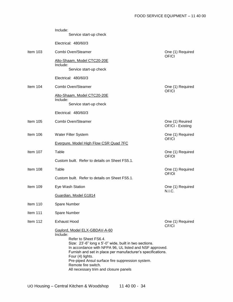
FOOD SERVICE EQUIPMENT – 11 40 00
UO Housing – Central Kitchen & Woodshop 11 40 00 - 34
Include: Service start-up check Electrical: 480/60/3 Item 103 Combi Oven/Steamer One (1) Required OF/CI Alto-Shaam, Model CTC20-20E Include: Service start-up check Electrical: 480/60/3 Item 104 Combi Oven/Steamer One (1) Required OF/CI Alto-Shaam, Model CTC20-20E Include: Service start-up check Electrical: 480/60/3 Item 105 Combi Oven/Steamer One (1) Reuired OF/CI - Existing Item 106 Water Filter System One (1) Required OF/CI Everpure, Model High Flow CSR Quad 7FC Item 107 Table One (1) Required OF/OI Custom built. Refer to details on Sheet FS5.1. Item 108 Table One (1) Required OF/OI Custom built. Refer to details on Sheet FS5.1. Item 109 Eye Wash Station One (1) Required N.I.C. Guardian, Model G1814 Item 110 Spare Number Item 111 Spare Number Item 112 Exhaust Hood One (1) Required CF/CI Gaylord, Model ELX-GBDAV-A-60 Include: Refer to Sheet FS6.4. Size: 23’-6” long x 5’-0” wide, built in two sections. In accordance with NFPA 96, UL listed and NSF approved. Furnish and set in place per manufacturer’s specifications. Four (4) lights. Pre-piped Ansul surface fire suppression system. Remote fire switch. All necessary trim and closure panels
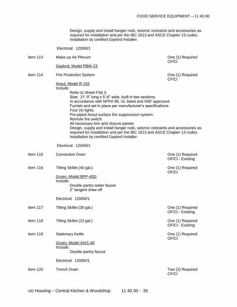
FOOD SERVICE EQUIPMENT – 11 40 00
UO Housing – Central Kitchen & Woodshop 11 40 00 - 35
Design, supply and install hanger rods, seismic restraints and accessories as required for installation and per the IBC 1613 and ASCE Chapter 13 codes. Installation by certified Gaylord Installer.
Electrical: 120/60/1 Item 113 Make-up Air Plenum One (1) Required CF/CI Gaylord, Model PBW-23 Item 114 Fire Protection System One (1) Required CF/CI Ansul, Model R-102 Include: Refer to Sheet FS6.3. Size: 21’-0” long x 5’-6” wide, built in two sections. In accordance with NFPA 96, UL listed and NSF approved. Furnish and set in place per manufacturer’s specifications. Four (4) lights. Pre-piped Ansul surface fire suppression system. Remote fire switch. All necessary trim and closure panels
Design, supply and install hanger rods, seismic restraints and accessories as required for installation and per the IBC 1613 and ASCE Chapter 13 codes. Installation by certified Gaylord Installer.
Electrical: 120/60/1 Item 115 Convection Oven One (1) Required OF/CI - Existing Item 116 Tilting Skillet (40 gal.) One (1) Required OF/CI Groen, Model BPP-40G Include: Double pantry water faucet 2” tangent draw-off Electrical: 120/60/1 Item 117 Tilting Skillet (30 gal.) One (1) Required OF/CI - Existing Item 118 Tilting Skillet (23 gal.) One (1) Required OF/CI - Existing Item 119 Stationary Kettle One (1) Required OF/CI Groen, Model AH/1-40 Include: Double pantry faucet Electrical: 120/60/1 Item 120 Trench Drain Two (2) Required CF/CI
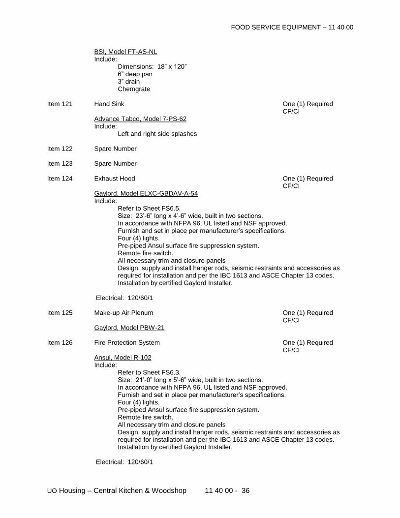
FOOD SERVICE EQUIPMENT – 11 40 00
UO Housing – Central Kitchen & Woodshop 11 40 00 - 36
BSI, Model FT-AS-NL Include: Dimensions: 18” x 120” 6” deep pan 3” drain Chemgrate Item 121 Hand Sink One (1) Required CF/CI Advance Tabco, Model 7-PS-62 Include: Left and right side splashes Item 122 Spare Number Item 123 Spare Number Item 124 Exhaust Hood One (1) Required CF/CI Gaylord, Model ELXC-GBDAV-A-54 Include: Refer to Sheet FS6.5. Size: 23’-6” long x 4’-6” wide, built in two sections. In accordance with NFPA 96, UL listed and NSF approved. Furnish and set in place per manufacturer’s specifications. Four (4) lights. Pre-piped Ansul surface fire suppression system. Remote fire switch. All necessary trim and closure panels
Design, supply and install hanger rods, seismic restraints and accessories as required for installation and per the IBC 1613 and ASCE Chapter 13 codes. Installation by certified Gaylord Installer.
Electrical: 120/60/1 Item 125 Make-up Air Plenum One (1) Required CF/CI Gaylord, Model PBW-21 Item 126 Fire Protection System One (1) Required CF/CI Ansul, Model R-102 Include: Refer to Sheet FS6.3. Size: 21’-0” long x 5’-6” wide, built in two sections. In accordance with NFPA 96, UL listed and NSF approved. Furnish and set in place per manufacturer’s specifications. Four (4) lights. Pre-piped Ansul surface fire suppression system. Remote fire switch. All necessary trim and closure panels
Design, supply and install hanger rods, seismic restraints and accessories as required for installation and per the IBC 1613 and ASCE Chapter 13 codes. Installation by certified Gaylord Installer.
Electrical: 120/60/1
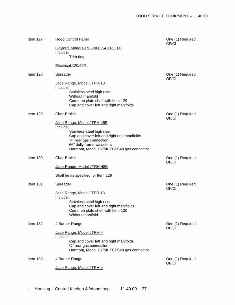
FOOD SERVICE EQUIPMENT – 11 40 00
UO Housing – Central Kitchen & Woodshop 11 40 00 - 37
Item 127 Hood Control Panel. One (1) Required CF/CI Gaylord, Model GPC-7000-S4-TR-1.00 Include: Trim ring Electrical:120/60/1 Item 128 Spreader One (1) Required OF/CI Jade Range, Model JTPR-18 Include: Stainless steel high riser Without manifold Common plate shelf with Item 129 Cap and cover left and right manifolds Item 129 Char-Broiler One (1) Required OF/CI Jade Range, Model JTRH-48B Include; Stainless steel high riser Cap and cover left and right end manifolds ¾” rear gas connection 66” dolly frame w/casters Dormont, Model 1675KITCFS48 gas connector Item 130 Char-Broiler One (1) Required OF/CI
Jade-Range, Model JTRH-48B Shall be as specified for Item 129
Item 131 Spreader One (1) Required OF/CI Jade Range, Model JTPR-18 Include: Stainless steel high riser Cap and cover left and right maniflolds Common plate shelf with Item 130 Without manifold Item 132 4 Burner Range One (1) Required OF/CI Jade Range, Model JTRH-4 Include: Cap and cover left and right manifolds ¾” rear gas connection Dormont, Model 1675KITCFS48 gas connector Item 133 4 Burner Range One (1) Required OF/CI Jade Range, Model JTRH-4
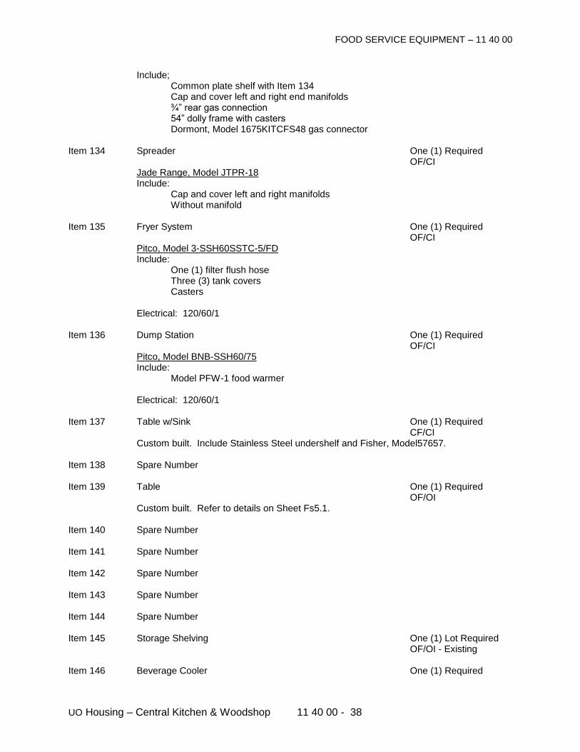
FOOD SERVICE EQUIPMENT – 11 40 00
UO Housing – Central Kitchen & Woodshop 11 40 00 - 38
Include; Common plate shelf with Item 134 Cap and cover left and right end manifolds ¾” rear gas connection 54” dolly frame with casters Dormont, Model 1675KITCFS48 gas connector Item 134 Spreader One (1) Required OF/CI Jade Range, Model JTPR-18 Include: Cap and cover left and right manifolds Without manifold Item 135 Fryer System One (1) Required OF/CI Pitco, Model 3-SSH60SSTC-5/FD Include: One (1) filter flush hose Three (3) tank covers Casters Electrical: 120/60/1 Item 136 Dump Station One (1) Required OF/CI Pitco, Model BNB-SSH60/75 Include: Model PFW-1 food warmer Electrical: 120/60/1 Item 137 Table w/Sink One (1) Required CF/CI Custom built. Include Stainless Steel undershelf and Fisher, Model57657. Item 138 Spare Number Item 139 Table One (1) Required OF/OI Custom built. Refer to details on Sheet Fs5.1. Item 140 Spare Number Item 141 Spare Number Item 142 Spare Number Item 143 Spare Number Item 144 Spare Number Item 145 Storage Shelving One (1) Lot Required OF/OI - Existing Item 146 Beverage Cooler One (1) Required
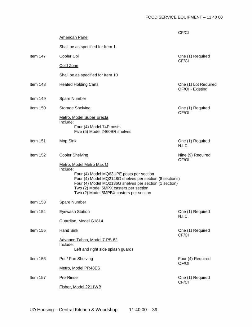
FOOD SERVICE EQUIPMENT – 11 40 00
UO Housing – Central Kitchen & Woodshop 11 40 00 - 39
CF/CI American Panel Shall be as specified for Item 1. Item 147 Cooler Coil One (1) Required CF/CI Cold Zone Shall be as specified for Item 10 Item 148 Heated Holding Carts One (1) Lot Required OF/OI - Existing Item 149 Spare Number Item 150 Storage Shelving One (1) Required OF/OI Metro, Model Super Erecta Include: Four (4) Model 74P posts Five (5) Model 2460BR shelves Item 151 Mop Sink One (1) Required N.I.C. Item 152 Cooler Shelving Nine (9) Required OF/OI Metro, Model Metro Max Q Include: Four (4) Model MQ63UPE posts per section Four (4) Model MQ2148G shelves per section (8 sections) Four (4) Model MQ2136G shelves per section (1 section) Two (2) Model 5MPX casters per section Two (2) Model 5MPBX casters per section Item 153 Spare Number Item 154 Eyewash Station One (1) Required N.I.C. Guardian, Model G1814 Item 155 Hand Sink One (1) Required CF/CI Advance Tabco, Model 7-PS-62 Include: Left and right side splash guards Item 156 Pot / Pan Shelving Four (4) Required OF/OI Metro, Model PR48ES Item 157 Pre-Rinse One (1) Required CF/CI Fisher, Model 2211WB
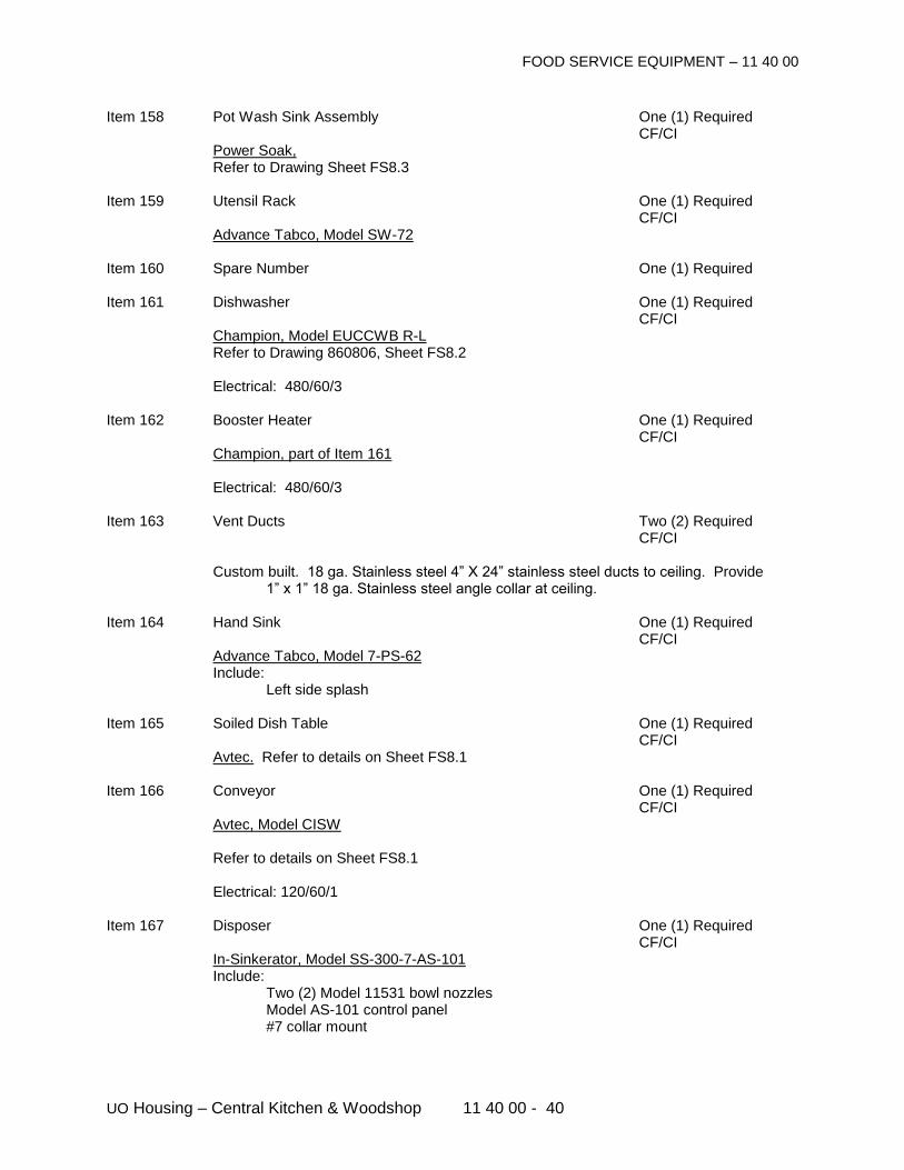
FOOD SERVICE EQUIPMENT – 11 40 00
UO Housing – Central Kitchen & Woodshop 11 40 00 - 40
Item 158 Pot Wash Sink Assembly One (1) Required CF/CI Power Soak, Refer to Drawing Sheet FS8.3 Item 159 Utensil Rack One (1) Required CF/CI Advance Tabco, Model SW-72 Item 160 Spare Number One (1) Required Item 161 Dishwasher One (1) Required CF/CI Champion, Model EUCCWB R-L Refer to Drawing 860806, Sheet FS8.2 Electrical: 480/60/3 Item 162 Booster Heater One (1) Required CF/CI Champion, part of Item 161 Electrical: 480/60/3 Item 163 Vent Ducts Two (2) Required CF/CI Custom built. 18 ga. Stainless steel 4” X 24” stainless steel ducts to ceiling. Provide
1” x 1” 18 ga. Stainless steel angle collar at ceiling. Item 164 Hand Sink One (1) Required CF/CI Advance Tabco, Model 7-PS-62 Include: Left side splash Item 165 Soiled Dish Table One (1) Required CF/CI Avtec. Refer to details on Sheet FS8.1 Item 166 Conveyor One (1) Required CF/CI Avtec, Model CISW Refer to details on Sheet FS8.1 Electrical: 120/60/1 Item 167 Disposer One (1) Required CF/CI In-Sinkerator, Model SS-300-7-AS-101 Include: Two (2) Model 11531 bowl nozzles Model AS-101 control panel #7 collar mount
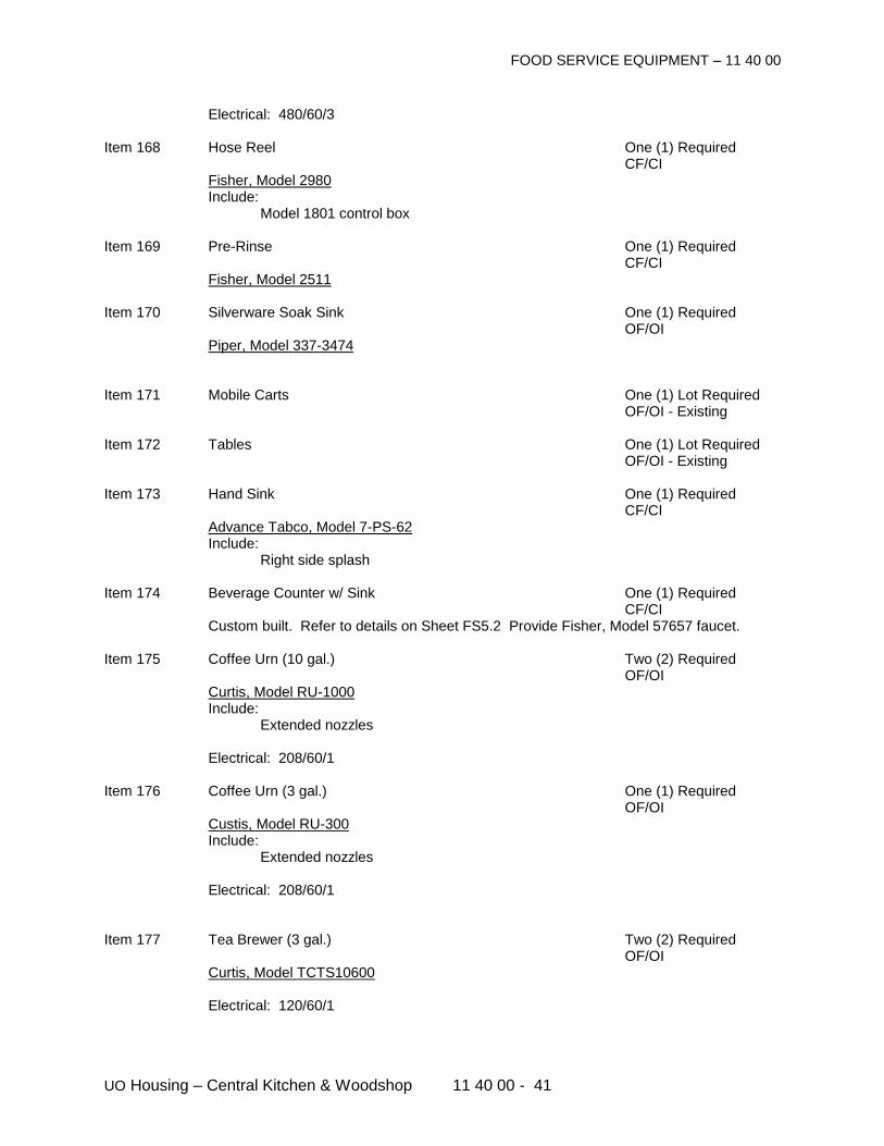
FOOD SERVICE EQUIPMENT – 11 40 00
UO Housing – Central Kitchen & Woodshop 11 40 00 - 41
Electrical: 480/60/3 Item 168 Hose Reel One (1) Required CF/CI Fisher, Model 2980 Include: Model 1801 control box Item 169 Pre-Rinse One (1) Required CF/CI Fisher, Model 2511 Item 170 Silverware Soak Sink One (1) Required OF/OI Piper, Model 337-3474 Item 171 Mobile Carts One (1) Lot Required OF/OI - Existing Item 172 Tables One (1) Lot Required OF/OI - Existing Item 173 Hand Sink One (1) Required CF/CI Advance Tabco, Model 7-PS-62 Include: Right side splash Item 174 Beverage Counter w/ Sink One (1) Required CF/CI Custom built. Refer to details on Sheet FS5.2 Provide Fisher, Model 57657 faucet. Item 175 Coffee Urn (10 gal.) Two (2) Required OF/OI Curtis, Model RU-1000 Include: Extended nozzles Electrical: 208/60/1 Item 176 Coffee Urn (3 gal.) One (1) Required OF/OI Custis, Model RU-300 Include: Extended nozzles Electrical: 208/60/1 Item 177 Tea Brewer (3 gal.) Two (2) Required OF/OI Curtis, Model TCTS10600 Electrical: 120/60/1
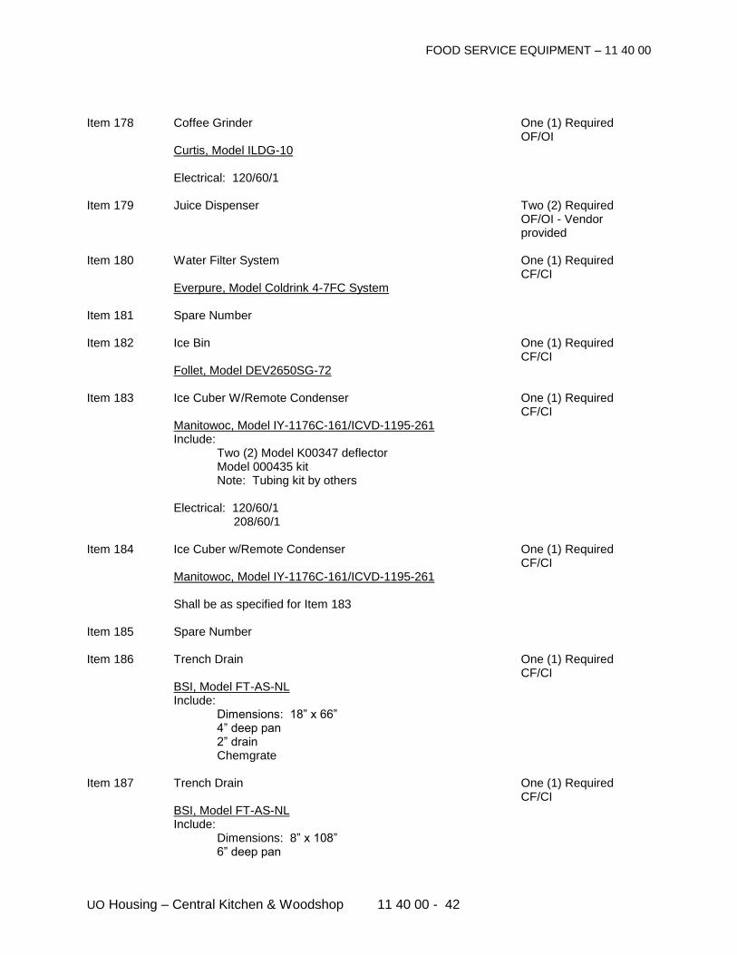
FOOD SERVICE EQUIPMENT – 11 40 00
UO Housing – Central Kitchen & Woodshop 11 40 00 - 42
Item 178 Coffee Grinder One (1) Required OF/OI Curtis, Model ILDG-10 Electrical: 120/60/1 Item 179 Juice Dispenser Two (2) Required
OF/OI - Vendor provided
Item 180 Water Filter System One (1) Required CF/CI Everpure, Model Coldrink 4-7FC System Item 181 Spare Number Item 182 Ice Bin One (1) Required CF/CI Follet, Model DEV2650SG-72 Item 183 Ice Cuber W/Remote Condenser One (1) Required CF/CI Manitowoc, Model IY-1176C-161/ICVD-1195-261 Include: Two (2) Model K00347 deflector Model 000435 kit Note: Tubing kit by others Electrical: 120/60/1 208/60/1 Item 184 Ice Cuber w/Remote Condenser One (1) Required CF/CI Manitowoc, Model IY-1176C-161/ICVD-1195-261 Shall be as specified for Item 183 Item 185 Spare Number Item 186 Trench Drain One (1) Required CF/CI BSI, Model FT-AS-NL Include: Dimensions: 18” x 66” 4” deep pan 2” drain Chemgrate Item 187 Trench Drain One (1) Required CF/CI BSI, Model FT-AS-NL Include: Dimensions: 8” x 108” 6” deep pan
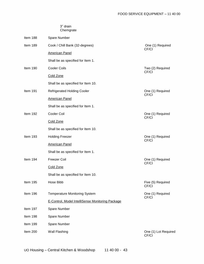
FOOD SERVICE EQUIPMENT – 11 40 00
UO Housing – Central Kitchen & Woodshop 11 40 00 - 43
3” drain Chemgrate Item 188 Spare Number Item 189 Cook / Chill Bank (32-degrees) One (1) Required CF/CI American Panel Shall be as specified for Item 1. Item 190 Cooler Coils Two (2) Required CF/CI Cold Zone Shall be as specified for Item 10. Item 191 Refrigerated Holding Cooler One (1) Required CF/CI American Panel Shall be as specified for Item 1. Item 192 Cooler Coil One (1) Required CF/CI Cold Zone Shall be as specified for Item 10. Item 193 Holding Freezer One (1) Required CF/CI American Panel Shall be as specified for Item 1. Item 194 Freezer Coil One (1) Required CF/CI Cold Zone Shall be as specified for Item 10. Item 195 Hose Bibb Five (5) Required CF/CI Item 196 Temperature Monitoring System One (1) Required CF/CI E-Control, Model IntelliSense Monitoring Package Item 197 Spare Number Item 198 Spare Number Item 199 Spare Number Item 200 Wall Flashing One (1) Lot Required CF/CI
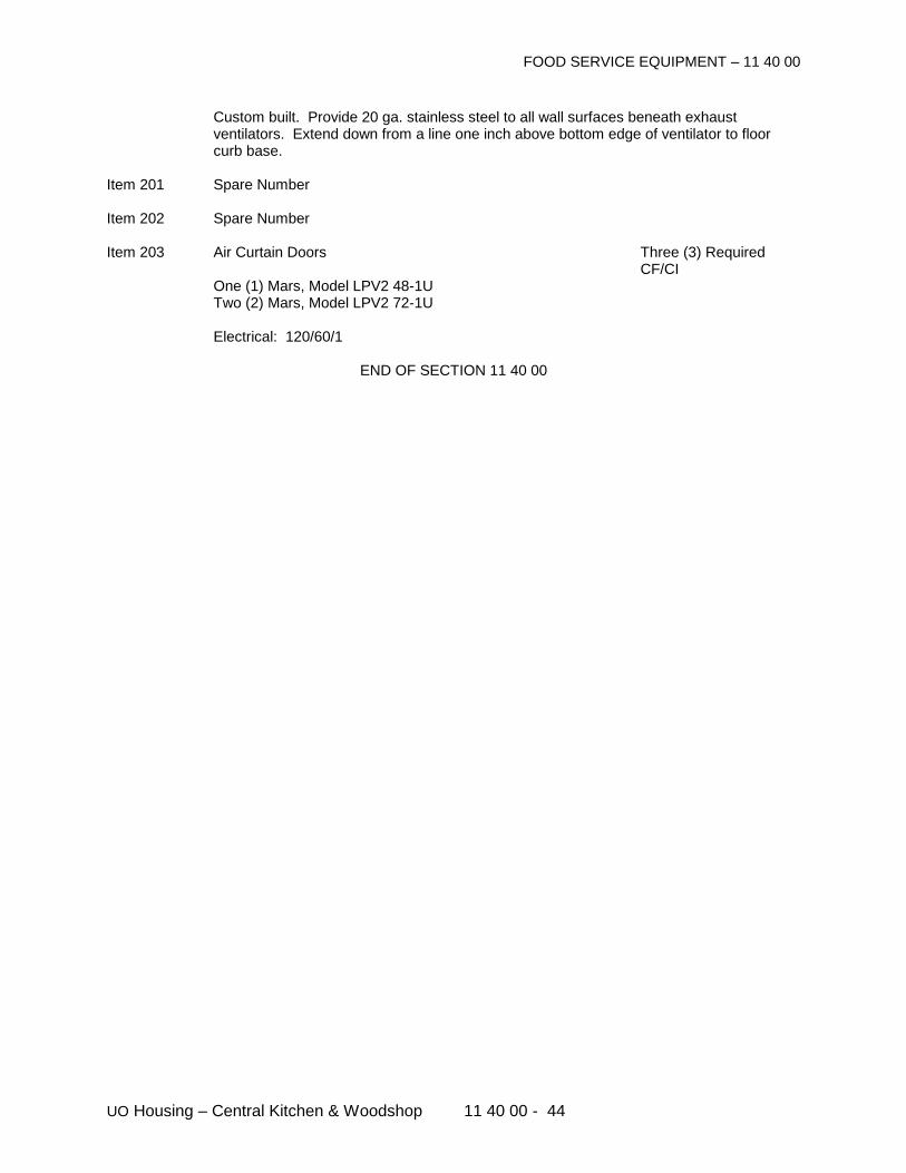
FOOD SERVICE EQUIPMENT – 11 40 00
UO Housing – Central Kitchen & Woodshop 11 40 00 - 44
Custom built. Provide 20 ga. stainless steel to all wall surfaces beneath exhaust ventilators. Extend down from a line one inch above bottom edge of ventilator to floor curb base.
Item 201 Spare Number Item 202 Spare Number Item 203 Air Curtain Doors Three (3) Required CF/CI One (1) Mars, Model LPV2 48-1U Two (2) Mars, Model LPV2 72-1U Electrical: 120/60/1
END OF SECTION 11 40 00
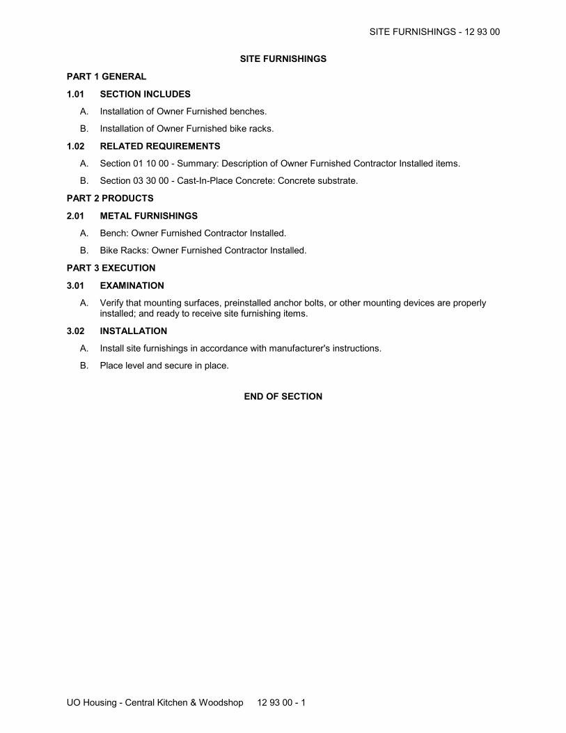
SITE FURNISHINGS - 12 93 00
UO Housing - Central Kitchen & Woodshop 12 93 00 - 1
SITE FURNISHINGS
PART 1 GENERAL
1.01 SECTION INCLUDES
A. Installation of Owner Furnished benches.
B. Installation of Owner Furnished bike racks.
1.02 RELATED REQUIREMENTS
A. Section 01 10 00 - Summary: Description of Owner Furnished Contractor Installed items.
B. Section 03 30 00 - Cast-In-Place Concrete: Concrete substrate.
PART 2 PRODUCTS
2.01 METAL FURNISHINGS
A. Bench: Owner Furnished Contractor Installed.
B. Bike Racks: Owner Furnished Contractor Installed.
PART 3 EXECUTION
3.01 EXAMINATION
A. Verify that mounting surfaces, preinstalled anchor bolts, or other mounting devices are properlyinstalled; and ready to receive site furnishing items.
3.02 INSTALLATION
A. Install site furnishings in accordance with manufacturer's instructions.
B. Place level and secure in place.
END OF SECTION
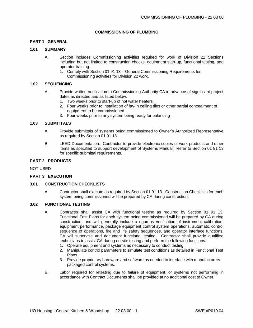
COMMISSIONING OF PLUMBING - 22 08 00
UO Housing - Central Kitchen & Woodshop 22 08 00 - 1 SWE #P010.04
COMMISSIONING OF PLUMBING PART 1 GENERAL
1.01 SUMMARY
A. Section includes Commissioning activities required for work of Division 22 Sections including but not limited to construction checks, equipment start-up, functional testing, and operator training. 1. Comply with Section 01 91 13 – General Commissioning Requirements for
Commissioning activities for Division 22 work.
1.02 SEQUENCING
A. Provide written notification to Commissioning Authority CA in advance of significant project dates as directed and as listed below. 1. Two weeks prior to start-up of hot water heaters 2. Four weeks prior to installation of lay-in ceiling tiles or other partial concealment of
equipment to be commissioned 3. Four weeks prior to any system being ready for balancing
1.03 SUBMITTALS
A. Provide submittals of systems being commissioned to Owner’s Authorized Representative as required by Section 01 91 13.
B. LEED Documentation: Contractor to provide electronic copies of work products and other items as specified to support development of Systems Manual. Refer to Section 01 91 13 for specific submittal requirements.
PART 2 PRODUCTS
NOT USED
PART 3 EXECUTION
3.01 CONSTRUCTION CHECKLISTS
A. Contractor shall execute as required by Section 01 91 13. Construction Checklists for each system being commissioned will be prepared by CA during construction.
3.02 FUNCTIONAL TESTING
A. Contractor shall assist CA with functional testing as required by Section 01 91 13. Functional Test Plans for each system being commissioned will be prepared by CA during construction, and will generally include a rigorous verification of instrument calibration, equipment performance, package equipment control system operations, automatic control sequence of operations, fire and life safety sequences, and operator interface functions. CA will supervise and document functional testing. Contractor shall provide qualified technicians to assist CA during on-site testing and perform the following functions. 1. Operate equipment and systems as necessary to conduct testing. 2. Manipulate control parameters to simulate test conditions as detailed in Functional Test
Plans. 3. Provide proprietary hardware and software as needed to interface with manufacturers
packaged control systems.
B. Labor required for retesting due to failure of equipment, or systems not performing in accordance with Contract Documents shall be provided at no additional cost to Owner.
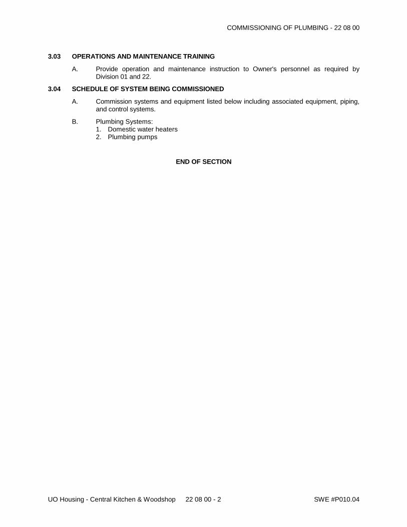
COMMISSIONING OF PLUMBING - 22 08 00
UO Housing - Central Kitchen & Woodshop 22 08 00 - 2 SWE #P010.04
3.03 OPERATIONS AND MAINTENANCE TRAINING
A. Provide operation and maintenance instruction to Owner's personnel as required by Division 01 and 22.
3.04 SCHEDULE OF SYSTEM BEING COMMISSIONED
A. Commission systems and equipment listed below including associated equipment, piping, and control systems.
B. Plumbing Systems: 1. Domestic water heaters 2. Plumbing pumps
END OF SECTION
COMMISSIONING OF HVAC - 23 08 00
UO Housing - Central Kitchen & Woodshop 23 08 00 - 1 SWE #P010.04
COMMISSIONING OF HVAC
PART 1 GENERAL
1.01 SUMMARY
A. Section includes Commissioning activities required for work of Division 23 Sections including but not limited to construction checks, equipment start-up, functional testing, and operator training. 1. Comply with Section 01 91 13 – General Commissioning Requirements for
Commissioning activities for Division 23 work.
1.02 SEQUENCING
A. Provide written notification to Commissioning Authority (CA) in advance of significant project dates as directed and as listed below. 1. Two weeks prior to start-up of air handling units, air-conditioning units, exhaust fans,
boilers and pumps 2. Four weeks prior to installation of lay-in ceiling tiles or other partial concealment of
equipment to be commissioned 3. Four weeks prior to any system ready for balancing
1.03 SUBMITTALS
A. Provide control system custom software, hardware, and technical manuals as necessary for development of Commissioning activities. Control system submittals include but are not limited to operating sequences, point database, workstation remote access, on-site custom programming/editing software, and programming and operations manual as necessary for development of Commissioning activities. Submit a minimum of 12 weeks prior to equipment start-up.
B. Provide sample control verification report to Commissioning Authority 12 weeks prior to substantial completion. Submittal shall show format and content of Final Verification Report.
C. Provide submittals of systems being commissioned to Owner’s Authorized Representative as required by Section 01 91 13.
D. Provide electronic copies (or hard copies where appropriate) of control system final configuration parameters, programs, databases, files, and electrical data as necessary to reconfigure and/or replace control components upon device failure.
E. LEED Documentation: Contractor to provide electronic copies of work products and other items as specified to support development of Systems Manual. Refer to Section 01 91 13 for specific submittal requirements.
PART 2 PRODUCTS
2.01 MATERIALS
A. Provide all necessary control hardware, software, and temporary licenses to enable Commissioning Authority to conduct activities and to fully access any electronic control systems furnished for this project. Commissioning Authorities’ laptop computer may be used for access if software and hardware systems provided are compatible with existing computer configuration, otherwise furnish laptop computer where required for duration of project.
COMMISSIONING OF HVAC - 23 08 00
UO Housing - Central Kitchen & Woodshop 23 08 00 - 2 SWE #P010.04
B. Provide minimum of two HVAC control operator interface sites for both on-site and remote access as described below: 1. Commissioning Authority Access Functions: Review and modification of control
programming, monitoring of control system operations, review and modification of software database, setup and monitoring trend data in tabular and graphical formats.
2. Remote Access: Remote access using Internet and shall include all functions described above.
3. Provide credentials for Commissioning Authority. Security access level shall be suitable to perform necessary commissioning functions.
4. Provide labor required to install hardware and software on personal computers at Commissioning Authority’s office. Software will be manufacturer’s most recent version and will be compatible with the CA’s personal computers. Provide Commissioning Authority with two hours training after fully functional remote access is established.
PART 3 EXECUTION
3.01 FIELD QUALITY CONTROL
A. Manufacturer's Field Services: Manufacturer's Representative to execute Construction Checklists and perform operational training as specified in Division 23 including the following systems: 1. Boilers 2. Packaged rooftop air-conditioners 3. Variable frequency drives 4. Building Automation System
3.02 CONSTRUCTION CHECKLISTS
A. Contractor shall execute as required by Section 01 91 13 Construction Checklists for each system commissioned will be prepared by Commissioning Authority during construction.
3.03 CONTROL VERIFICATION REPORTS
A. Building Automation System: BAS control contractor shall perform verification of the function and performance of control hardware and software. Provide verification report demonstrating proper system installation and operation. Verification report shall include the following: 1. Network Communication: Verify that all network devices properly communicate on
network. Verify communication speed and reliability is acceptable. 2. Input and Output Verification:
a. Verify that all input and output points are indicating properly. Verification tests shall be “end-to-end” meaning field measurement to workstation graphic display value.
b. Calibrate all analog inputs. Acceptance accuracy shall be as specified for product accuracy. Repair or replace all devices that do not conform to specified accuracy.
c. Operate all analog outputs from 0% to 100% of operating range. Verify that controlled device operates over the entire output range and that maximum and minimum operating conditions are achieved.
d. Valves and dampers shall close fully and provide tight shutoff. Leakage rates shall not exceed specified values.
e. Verify that all digital outputs operate controlled devices.
3. Sequence of Operation Verification: Systematically verify automatic control sequence of operation functions in field after installation is complete. Verification stall include: a. Time scheduling b. Operating modes c. Tune and adjust control loops and control sequences to optimize efficiency and
performance. Control loops shall be stable and maintain desired setpoints.
COMMISSIONING OF HVAC - 23 08 00
UO Housing - Central Kitchen & Woodshop 23 08 00 - 3 SWE #P010.04
4. Trending: Confirm trending utilities storage of operating data as required to verify operation and performance of control modes, sequence, and loops. Meet with Owner and CA to review configuration, parameter interval, and duration prior to trend setup.
5. Operator Interface: Review function of operator interface. Confirm that graphic operator interface accurately depicts as-constructed system configuration and that all required content is displayed and functions as intended.
6. Alarms: Confirm alarm utilities are configured as required, alarm conditions are displaying in alarm logs, on graphic displays, and provide annunciation and reporting as required. Meet with Owner and CA to review configuration parameters prior to alarm utility setup.
7. Coordination: Assist balancing contractor with development of control setpoints and parameters as specifically indicated or otherwise required to provide Sequence of Operation. Setpoints would include but would not be limited to actuator positions required to provide minimum ventilation rates, supply air pressure setpoints for variable air volume air distribution systems, and terminal unit calibration parameters.
8. Controls Verification Report: After system operation is completely verified, provide written certification to Owner that systems have been fully tested, are operating according to specifications and ready for functional testing. Include documentation to the Commissioning Authority detailing verification results. Report shall include: a. Updated control construction drawings and equipment data that incorporates all
changes made during construction b. Printed as-built control code c. Printed point data base d. Input/Output Verification Log: Submit point verification log including point
identification, control system readout value, verification measurement, and required calibration offset where applied.
e. Sequence of Operation Verification: Submit verification test report listing complete text of control sequence and test results. Verify all specified control sequences.
f. Trend Logs: Submit printed trend reports for the following: i. Time schedules. Seven-day log demonstrating that equipment operates
according to programmed time schedules. ii. Automatic control sequences. Trends shall be set-up as follows:
(i) Analog Control: Points that modulate over time shall be sampled at appropriate intervals and durations to demonstrate proper operating sequences. For example, a discharge temperature control loop would require trending during the morning warm-up mode and normal daytime operation mode. Each trend shall include all measured variables, control output signal, actual output signal, and controlled variable.
(ii) Digital Control: Dual-state control or monitoring points shall be recorded as COV (+) or change of value meaning that the changed parameter only needs to be recorded after the value changes from its previous state. A minimum of one week of samples shall be provided to properly demonstrate equipment cycles, modes, and schedules.
g. Include trend graphs as described below: i. Lines shall be labeled and shall be distinguishable from each other by using
either different line types, or different line colors. ii. Indicate engineering units of the y-axis values; e.g., degrees F., inches w.g.,
Btu/lb, percent wide open, etc. iii. The y-axis scale shall be chosen so that all trended values are in a readable
range. Do not mix trended values on one graph if their unit ranges are incompatible.
iv. All points trended for one HVAC subsystem; e.g., air handling unit, chilled water system, etc. shall be trended during the same trend period.
v. Each graph shall be clearly labeled with HVAC subsystem title, date, and times.
h. List of incomplete work.
COMMISSIONING OF HVAC - 23 08 00
UO Housing - Central Kitchen & Woodshop 23 08 00 - 4 SWE #P010.04
9. Demonstration: Demonstrate operation of control system to Engineer, Commissioning Authority, and Owner including: a. Menu functions b. Point overrides c. Control loop response after point modification d. Alarm response time
3.04 FUNCTIONAL TESTING
A. Contractor shall assist Commissioning Authority with functional testing as required by Section 01 91 13. Functional Test Plans for each system being commissioned will be prepared by Commissioning Authority during construction, and will generally include a rigorous verification of instrument calibration, equipment performance, packaged equipment control system operations, automatic control sequence of operations, fire and life safety sequences, and operator interface functions. Commissioning Authority will supervise and document functional testing. Contractor shall provide qualified technicians to assist Commissioning Authority during on-site testing and perform the following functions. 1. Operate equipment and systems as necessary to conduct testing. 2. Manipulate control parameters to simulate test conditions as detailed in Functional Test
Plans. 3. Access control programming and database as required to verify control configuration or
to correct observed deficiencies. 4. Create graphic displays and/or trend report as required to document test results. 5. Provide proprietary hardware and software as needed to interface with manufacturer’s
packaged control systems.
B. Labor required for retesting due to failure of equipment, or systems not performing in accordance with Contract Documents shall be provided at no additional cost to Owner.
3.05 OPERATIONS AND MAINTENANCE TRAINING
A. Provide operation and maintenance instruction to Owner's personnel as required by Division 01 and 23.
3.06 SCHEDULE OF SYSTEMS BEING COMMISSIONED
A. Commission systems and equipment listed below including associated equipment, piping, ductwork, and control systems.
B. HVAC Systems: HVAC systems, equipment, and controls
END OF SECTION
COMMISSIONING OF ELECTRICAL - 26 08 00
UO Housing - Central Kitchen & Woodshop 26 08 00 - 1 SWE #P010.04
COMMISSIONING OF ELECTRICAL
PART 1 GENERAL
1.01 SUMMARY
A. Section includes Commissioning activities required for work of Division 26 Sections including but not limited to construction checks, equipment start-up, functional testing, and operator training. 1. Comply with Section 01 91 13 – General Commissioning Requirements for
Commissioning activities for Division 26 work.
1.02 SEQUENCING
A. Provide written notification to Commissioning Authority (CA) in advance of significant project dates including but not limited to the following: 1. Two weeks prior to Manufacturer’s start-up of lighting control system
1.03 SUBMITTALS
A. Provide submittals of systems being commissioned to Owner’s Authorized Representative as required by Section 01 91 13 COMMISSIONING REQUIREMENTS.
B. LEED Documentation: Contractor to provide electronic copies of work products and other items as specified to support development of Systems Manual. Refer to Section 01 91 13 for specific submittal requirements.
PART 2 PRODUCTS
NOT USED
PART 3 - EXECUTION
3.01 FIELD QUALITY CONTROL
A. Manufacturer's Field Services: Manufacturer's representative to perform construction checks and operational training as specified in Division 26 including the following systems: 1. Lighting Control System
3.02 CONSTRUCTION CHECKLISTS
A. Contractor shall perform as required by Section 01 91 13. Construction checklists for each system being commissioned will be prepared by Commissioning Authority during construction. 1. Perform voltage and amperage measurements for mechanical equipment as required
in Section 22 08 00 and 23 08 00.
3.03 LIGHTING CONTROL VERIFICATION REPORT
A. Control Contractor shall perform construction checks, start-up, and verification of automatic lighting control system. Provide verification report demonstrating proper system installation and operation. Verification shall include the following: 1. Equipment Startup: All equipment being controlled shall be initially started and tested
as required by the manufacturer. All required manufacturer installation and start-up checklists shall attached to the construction checklists.
2. Communication Network Startup: Verify that all lighting control panels properly communicate on network. Verify communication speed and reliability is acceptable.
3. Software Verification: All programs and software functions shall be verified for proper sequence of operation.
COMMISSIONING OF ELECTRICAL - 26 08 00
UO Housing - Central Kitchen & Woodshop 26 08 00 - 2 SWE #P010.04
4. Controls Verification Report: After system operation is completely verified, provide written certification to Owner that systems have been fully tested and are operating according to specifications and ready for functional testing. Include report to the CA detailing verification results and the dates, times and person(s) performing startup. Report shall include: a. Device Calibration Log b. Lighting Relay Control Panels
1) Provide date, time, panel designation, and panel location. 2) Provide a list of all programmed time schedules. 3) Provide a list of all sweep times, sweep control on or off, and relays that are swept
off. 4) Provide a list of all group load assignments. 5) Provide all photocell control parameters and setpoints. 6) Provide a checkout document indicating the following:
a. Lighting relay panel designation b. Relay number c. Relay description d. Power circuit feeding relay e. Verified relay operation f. Verified time schedule control g. Verified sweep control h. Verified photocell control
c. Low Voltage Switches 1) Provide a verification document indicating the following:
a) Switch location b) Verified switch operation c) Verified switch override operation d. Occupancy Sensors
1) Provide a verification document indicating the following: a) Room or space designation b) Manufacturer c) Model d) Technology type e) DIP settings f) Trigger settings g) Time delay settings h) Sensitivity settings i) Verified sensor operation
e. Daylight Compensation Systems 1) Provide a verification report indicating the following:
a) Provide date and time. b) Room or space designation c) Manufacturer d) Model e) Light level maintained at the work plane f) Average light level with all electric lights off and no window obstruction g) Average light level with electric lights on and no window obstruction h) Average light level with electric lights on and at minimum output with no
window obstruction i) Average light level with electric lights on and at maximum output with no
window obstruction j) Average light level with electric lights on at maximum output at night or with
windows obstructed k) Average light level with electric lights on at minimum output at night or with
windows obstructed l) Provide all parameters and settings for all devices.
f. Digitally Addressable Lighting Interface Systems
COMMISSIONING OF ELECTRICAL - 26 08 00
UO Housing - Central Kitchen & Woodshop 26 08 00 - 3 SWE #P010.04
1) Calibration Log a) Provide date, time control system readout, means of verification, verification
measurement, and calibration parameters for each analog input. 2) Point Summary Log
a) Attach printed log showing detailed descriptive data and configuration parameters for all points.
3) Operational Trend Logs: Include trend logs as follows: a) Trend data for all analog and digital points.
i. Analog Control: Points that modulate over time shall be sampled at appropriate intervals and durations to demonstrate properly operating sequences. Provide one sample every 5 minutes for at least one week.
ii. Digital Control: Dual-state control or monitoring points shall be recorded as COV (change of value). A minimum of one week of samples shall be provided to properly demonstrate equipment cycles, modes, and schedules.
5. Demonstration: Demonstrate operation of control system to Engineer, CA, and Owner including: a. Menu functions b. Relay overrides c. Programming of relays, time schedules
3.04 FUNCTIONAL TESTING
A. Contractor shall perform testing as directed by Commissioning Authority and as required by Section 01 91 13. Functional Test Plans for each system being commissioned will be prepared by Commissioning Authority during construction. Provide an allowance of on-site labor hours per trade for assisting Commissioning Authority with Functional Testing as listed below. Labor required for retesting due to failure of equipment or systems to perform in accordance with Contract Documents shall be provided at no additional cost to Owner.
3.05 OPERATIONS AND MAINTENANCE TRAINING
A. Provide operation and maintenance instruction to Owner's personnel as required by Division 01 and 26.
3.06 SCHEDULE OF SYSTEMS BEING COMMISSIONED
A. Commission systems and equipment listed below including associated equipment and control systems. 1. Automatic Lighting Control System
END OF SECTION
EARTH MOVING – 31 20 00
UO Housing – Central Kitchen & Woodshop 31 20 00 - 1
EARTH MOVING
PART 1 - GENERAL
1.1 SUMMARY
A. Section Includes: 1. Preparing subgrades 2. Excavating and backfilling for buildings and structures. 3. Drainage course for concrete slabs-on-grade. 4. Base course for concrete walks & pavements. 5. Base course or asphalt paving. 6. Excavating and backfilling for utility trenches. 7. Drainage fill for infiltration facilities. 8. Growing media for rain gardens.
1.2 SUBMITTALS
A. Product Data.
B. Aggregate Sieve Analysis.
C. Growing media: (at least 14 days in advance of construction). 1. Documentation for the two analyses described in article 2.1.N.1 and 2.1.N.2 of this
specification (particle gradation with calculated coefficient of uniformity; and pH) shall be performed by an accredited laboratory with certification maintained current. The date of the analyses shall be no more than 90 calendar days prior to the date of the submittal. The report shall include the following information:
a. Name and address of the laboratory. b. Phone contact and e-mail address for the laboratory. c. Test data, including the date and name of the test procedure.
2. A compost technical data sheet from the compost vendor. The analysis and report must conform to the sampling and reporting requirements of the US composting Council Seal of Testing Assurance (STA) program. The analysis shall be performed and reported by an approved independent STA program laboratory and be no more than 90 calendar days prior to the date of submittal.
3. Two gallon-sized bags of the blended material. 4. A description of the location, equipment, and method proposed to mix the material.
D. Infiltration test results.
1.3 DEFINITIONS
A. Backfill: Soil material used to fill an excavation. 1. Initial Backfill: Backfill placed beside and over pipe in a trench, including haunches to
support sides of pipe. 2. Final Backfill: Backfill placed over initial backfill to fill a trench.
B. Base Course: Course placed between the subbase course, or subgrade, and concrete, or hot-mix asphalt paving.
C. Bedding Course: Course placed over the excavated subgrade in a trench before laying pipe.
D. Borrow Soil: Satisfactory soil imported from off-site for use as fill or backfill.
E. Drainage Course: Course supporting the slab-on-grade that also minimizes upward capillary flow of pore water.
F. Excavation: Removal of material encountered above subgrade elevations and to lines and dimensions indicated.
EARTH MOVING – 31 20 00
UO Housing – Central Kitchen & Woodshop 31 20 00 - 2
1. Authorized Additional Excavation: Excavation below subgrade elevations or beyond indicated lines and dimensions as directed by Architect. Authorized additional excavation and replacement material will be paid for according to Contract provisions for changes in the Work.
2. Unauthorized Excavation: Excavation below subgrade elevations or beyond indicated lines and dimensions without direction by Architect. Unauthorized excavation, as well as remedial work directed by Architect, shall be without additional compensation.
G. Fill: Soil materials used to raise existing grades.
H. Structures: Buildings, footings, foundations, retaining walls, slabs, tanks, curbs, mechanical and electrical appurtenances, or other man-made stationary features constructed above or below the ground surface.
I. Subgrade: Surface or elevation remaining after completing excavation, or the top surface of a fill or backfill immediately below subbase, drainage fill, drainage course, or topsoil materials.
J. Utilities: On-site underground pipes, conduits, ducts, and cables, as well as underground services within buildings.
K. Drainage Fill: Free draining, open-graded aggregate course used to support pervious pavement or in drainage zones in flow-through planters, vegetated stormwater facilities and infiltration galleries.
L. Growing media: Non-native soil mixture made up of sand, loam, and compost; used on surface stormwater facilities.
M. Unified Soil Classification System: 1. GW: Well-graded gravels; gravel/sand mixtures with little or no fines. 2. GP: Poorly-graded gravels; gravel/sand mixtures with little or no fines. 3. GM: Silty gravels; poorly-graded gravel/sand/silt mixtures. 4. GC: Clayey gravels; poorly-graded gravel/sand/clay mixtures. 5. SW: Well-graded sands’ gravelly sands with little or no fines. 6. SP: Poorly-graded sands; gravelly sands with little or no fines. 7. SM: Silty sands; poorly, graded- sand/gravel/silt mixtures. 8. SC: Clayey sands; poorly-graded sand/gravel/clay mixtures. 9. ML: Inorganic silts; sandy, gravelly, or clayey silts. 10. CL: Lean clays; inorganic, gravelly, sandy, or silty, low to medium-plasticity clays. 11. OL: Organic, low-plasticity clays and silts. 12. MH: Inorganic, elastic silts; sandy, gravelly or clayey elastic silts 13. CH: Fat clays; high-plasticity, inorganic clays. 14. OH: Organic, medium to high-plasticity clays and silts 15. PT: Peat, humus, hydric soils with high organic content.
1.4 PROJECT CONDITIONS
A. Utility Locator Service: Notify utility locator service for area where Project is located before beginning earth moving operations.
B. Existing Utilities: Do not interrupt utilities serving facilities occupied by Owner or others unless permitted in writing by Architect and then only after arranging to provide temporary utility services according to requirements indicated.
C. Site Information: Research public utility records and verify existing utility locations prior to ordering any material. Notify the Architect immediately if any discrepancies are found in the project survey.
D. See Geotechnical report titled Geotechnical Investigation by GRI dated June 11, 2013 for additional information and requirements.
EARTH MOVING – 31 20 00
UO Housing – Central Kitchen & Woodshop 31 20 00 - 3
PART 2 - PRODUCTS
2.1 SOIL MATERIALS
A. General: Provide borrow soil materials when sufficient satisfactory soil materials are not available from excavations.
B. Satisfactory Soils: Soil Classification Groups GW, GP, GM, SW, SP, and SM according to ASTM D 2487, or a combination of these groups; free of rock or gravel larger than 3 inches in any dimension, debris, waste, frozen materials, vegetation, and other deleterious matter.
C. Unsatisfactory Soils: Soil Classification Groups GC, SC, CL, ML, OL, CH, MH, OH, and PT according to ASTM D 2487, or a combination of these groups. 1. Unsatisfactory soils also include satisfactory soils not maintained within 2 percent of
optimum moisture content at time of compaction.
D. Base Course: Naturally or artificially graded mixture of natural or crushed gravel, crushed stone, and natural or crushed sand; ASTM D 2940; with at least 95 percent passing a 1-1/2-inch sieve and not more than 8 percent passing a No. 200 sieve or use Oregon Standard Specifications for Construction 1-inch-0-inch or ¾-inch-0-inch BASE AGGREGATE.
E. Engineered Fill: Naturally or artificially graded mixture of natural or crushed gravel, crushed stone, and natural or crushed sand; ASTM D 2940; with at least 90 percent passing a 3-inch sieve and not more than 12 percent passing a No. 200 sieve.
F. Bedding Course: Naturally or artificially graded mixture of natural or crushed gravel, crushed stone, and natural or crushed sand; ASTM D 2940; except with 100 percent passing a 1-inch sieve and not more than 8 percent passing a No. 200 sieve or use Oregon Standard Specifications for Construction ¾-inch—0-inch BASE AGGREGATE.
G. Drainage Course: Narrowly graded mixture of washed crushed stone, or crushed or uncrushed gravel; ASTM D 448; coarse-aggregate grading Size 57; except with 100 percent passing a 1-1/2-inch sieve and less than 2% passing the No. 200 sieve. May use ¾-to-1/4 inch crushed rock. See “Subdrainage and Floor Support” section of Geotechnical Report.
H. Backfill and Fill: 1. Satisfactory soil materials 2. Initial trench backfill: Use OREGON STANDARD SPECIFICATIONS FOR
CONSTRUCTION (3/4-inch – 0-inch) base aggregate.
I. Drainage Fill: Angular, granular material with a maximum particle size of 2 inches and shall meet Oregon Standard Specification 00430.11. The material shall be free of roots, organic material, and other unsuitable materials; have less than 2 percent passing the No. 200 sieve (washed analysis); and have at least two mechanically fractured faces.
J. Growing Media: A loose and friable material blend of loamy soil, sand and compost that is 30-40 percent compost (by volume) and meets the following other criteria: 1. Particle Gradation: A sieve analysis of the complete blended material shall be conducted
per ASTM C117/C136, AASHTO T11/T27, or ASTM D422/D140 and meet the following gradation criteria:
Sieve Size Percent Passing
1-inch 100
#4 75-100
#10 40-100
#40 15-50
#100 5-25
#200 5-15
The blend shall have a coefficient of uniformity (D60/D10) equal to or greater than 6 to ensure it is well graded.
2. Acidity: pH of the blended material shall be tested and be between 6 and 8.
EARTH MOVING – 31 20 00
UO Housing – Central Kitchen & Woodshop 31 20 00 - 4
3. Compost: The compost shall be derived from plant material and provided by a member of the US Composting Council Seal of Testing Assurance (STA) program. See www.compostingcouncil.org for a list of local providers. The compost shall be a result of biological degradation and transformation of plant-derived materials under conditions designed to promote aerobic decomposition. The material shall be well composted, free of viable weed seeds, and stable with regard to oxygen consumption and carbon dioxide generation. The compost shall have no visible free water and produce no dust when handled. It shall meet the following criteria, as reported by the US Composting Council STA Compost Technical Data Sheet provided by the vendor.
a. 100 percent of the material must pass through a ½ inch screen. b. The pH of the material shall be between 6 and 8. c. Manufactured inert material (plastic, concrete, ceramics, metal, etc.) shall be less
than 1.0 percent by weight. d. The organic matter content shall be between 30 and 70 percent (dry weight basis). e. Soluble salt content shall be less than 6.0 mmhos/cm. f. Maturity indicator shall be greater than 80 percent for Germination and Vigor. g. Stability shall be ‘Stable’ to ‘Very Stable’. h. Carbon/Nitrogen (C/N) ratio shall be less than 25:1. i. Trace metals test result= ‘Pass.’
4. Blend: The material shall be well mixed and homogenous. It shall be free of wood pieces, plastics, and other foreign matter. There shall be no visible free water.
5. Infiltration: The blended material shall have a minimum infiltration rate of 2 inches per hour. Contractor shall provide the Engineer with a 2 quart sample for initial testing.
2.2 ACCESSORIES
A. Detectable Warning Tape: Acid- and alkali-resistant, polyethylene film warning tape manufactured for marking and identifying underground utilities, a minimum of 6 inches wide and 4 mils thick, continuously inscribed with a description of the utility, with metallic core encased in a protective jacket for corrosion protection, detectable by metal detector when tape is buried up to 30 inches deep; colored to comply with local practice or requirements of authorities having jurisdiction or as follows: 1. Red: electric. 2. Yellow: Gas, oil, steam, and dangerous materials. 3. Orange: telephone and other communications. 4. Blue: Water systems. 5. Green: Sewer systems.
B. Tracer Wire: 12 AWG minimum solid copper insulated High Molecular Weight Polyethylene (HMW PE) tracer wire or approved equal. The tracer wire insulation shall be green for sewer pipe and blue for waterlines and be a minimum of 45 mil. thick. Joints or splices shall be waterproof. The wire shall be rated for 30 Volt.
C. Drainage Fabric: Nonwoven geotextile, specifically manufactured as a drainage geotextile; made from polyolefins, polyesters, or polyamides; and with the following minimum properties determined according to ASTM D 4759 and referenced standard test methods: 1. Grab Tensile Strength: 110 lbf; ASTM D 4632. 2. Tear Strength: 40 lbf; ASTM D 4533. 3. Puncture Strength: 220 lbf; ASTM D 4833. 4. Apparent Opening Size: No. 40; ASTM D 4751. 5. Permativity (minimum): .5 sec-1; ASTM D 4491.
D. Separation Fabric: Woven geotextile, specifically manufactured as a separation geotextile; made from polyolefins, polyesters, or polyamides; and with the following minimum properties determined according to ASTM D 4759 and referenced standard test methods: 1. Grab Tensile Strength: 180 lbf; ASTM D 4632. 2. Tear Strength: 68 lbf; ASTM D 4533. 3. Puncture Strength: 371 lbf; ASTM D 4833. 4. Apparent opening size: No. 30; ASTM D 4751.
EARTH MOVING – 31 20 00
UO Housing – Central Kitchen & Woodshop 31 20 00 - 5
PART 3 - EXECUTION
3.1 PREPARATION
A. Protect structures, utilities, sidewalks, pavements, and other facilities from damage caused by settlement, lateral movement, undermining, washout, and other hazards created by earth moving operations. Provide protective insulating materials as necessary.
B. Preparation of subgrade for earthwork operations including removal of vegetation, topsoil, debris, obstructions, and deleterious materials from ground surface is specified in Division 31 Section “Site Clearing.”
C. Protect and maintain erosion and sedimentation controls, as required by 1200-CN permit during earth moving operations.
D. Prevent surface water and ground water from entering excavations, from ponding on prepared subgrades, and from flooding Project site and surrounding area.
E. Protect subgrades and foundation soils from freezing temperatures and frost. Remove temporary protection before placing subsequent materials.
F. Protect subgrades from softening, undermining, washout, and damage by rain or water accumulation.
G. Protect all areas designated to be infiltration facilities from foot or equipment traffic and surface water runoff. Do not use proposed infiltration facilities to dispose of surface water runoff during construction. Under no circumstances shall material and equipment be stored on top of the installation area. Contractor shall not backfill facility until Engineer has inspected it and signed off.
H. Protect all areas designated to receive pervious pavers or pervious pavement from excessive compaction.
3.2 EXPLOSIVES
A. Explosives: Do not use explosives.
3.3 EXCAVATION
A. Unclassified Excavation: Excavate to subgrade elevations regardless of the character of surface and subsurface conditions encountered. Unclassified excavated materials may include rock, soil materials, and obstructions. No changes in the Contract Sum or the Contract Time will be authorized for rock excavation or removal of obstructions without prior approval by the Architect. 1. If excavated materials intended for fill and backfill include unsatisfactory soil materials
and rock, replace with satisfactory soil materials.
3.4 EXCAVATION FOR STRUCTURES
A. Excavate to indicated elevations and dimensions within a tolerance of plus or minus 1 inch. If applicable, extend excavations a sufficient distance from structures for placing and removing concrete formwork, for installing services and other construction, and for inspections. 1. Excavations for Footings and Foundations: Do not disturb bottom of excavation.
Excavate by hand to final grade just before placing concrete reinforcement. Trim bottoms to required lines and grades to leave solid base to receive other work.
3.5 EXCAVATION FOR WALKS AND PAVEMENTS
A. Excavate surfaces under walks and pavements to indicated lines, cross sections, elevations, and subgrades.
3.6 EXCAVATION FOR UTILITY TRENCHES
A. Excavate trenches to indicated gradients, lines, depths, and elevations.
EARTH MOVING – 31 20 00
UO Housing – Central Kitchen & Woodshop 31 20 00 - 6
B. Excavate trenches to uniform widths to provide the following clearance on each side of pipe or conduit. Excavate trench walls vertically from trench bottom to 12 inches higher than top of pipe or conduit unless otherwise indicated. 1. Clearance: 6 inches each side of pipe or conduit.
C. Trench Bottoms: Excavate and shape trench bottoms to provide uniform bearing and support of pipes and conduit. Shape subgrade and bedding course to provide continuous support for bells, joints, and barrels of pipes and for joints, fittings, and bodies of conduits. Remove projecting stones and sharp objects along trench subgrade. 1. Excavate trenches 6 inches deeper than elevation required in rock or other unyielding
bearing material, 4 inches deeper elsewhere, to allow for bedding course. Hand excavate for bell of pipes.
2. Excavate utility structures to provide 6 inches clearance (enlarge as needed) to allow for compaction of backfill material.
3.7 EXCAVATION FOR STORMWATER INFILTRATION FACILITIES
A. Excavate facilities to the indicated gradients, lines, depths, and elevations. All excavations shall be performed with the lightest practical excavation equipment. Excavation equipment shall not be operated within the limits of the facility.
B. To help prevent subgrade soil contamination and clogging by sediment, facility construction shall be delayed until all other construction within its drainage basin is completed and the drainage area stabilized. Provide additional sediment control measures such as diversion berms around the facility as needed. Additional excavation and backfill required to restore any infiltration rate lost due to clogging or over-compaction during construction shall be performed by the contractor at no cost to the owner.
3.8 SUBGRADE INSPECTION
A. Proof-roll subgrade with a pneumatic-tired dump truck to identify soft pockets and areas of excess yielding. Do not proof-roll wet or saturated subgrades. Do not proof-roll subgrade in infiltration facilities.
B. Soft pockets and areas of excess yielding that have been identified shall be scarified and moistened or aerated, or removed and replaced with suitable soil materials to the depth required. Re-compact and retest until specified compaction is obtained.
C. Reconstruct subgrades damaged by freezing temperatures, frost, rain, accumulated water, or construction activities, as directed by Architect, without additional compensation.
3.9 UNAUTHORIZED EXCAVATION
A. Fill unauthorized excavation under foundations or wall footings by extending bottom elevation of concrete foundation or footing to excavation bottom, without altering top elevation. Lean concrete fill, with 28-day compressive strength of 2500 psi, may be used when approved by Architect. 1. Fill unauthorized excavations under other construction, pipe, or conduit as directed by
Architect.
3.10 STORAGE OF SOIL MATERIALS
A. Stockpile borrow soil materials and excavated satisfactory soil materials without intermixing. Place, grade, and shape stockpiles to drain surface water. Cover to prevent windblown dust. 1. Stockpile soil materials away from edge of excavations. Do not store within drip line of
remaining trees.
3.11 BACKFILLS AND FILLS
A. Backfill: Place and compact backfill in excavations promptly, but not before completing the following: 1. Construction below finish grade including, where applicable, dampproofing,
waterproofing, and perimeter insulation.
EARTH MOVING – 31 20 00
UO Housing – Central Kitchen & Woodshop 31 20 00 - 7
2. Surveying locations of underground utilities for record documents. 3. Inspecting and testing underground utilities. 4. Removing concrete formwork. 5. Removing trash and debris. 6. Removing temporary shoring and bracing, and sheeting. 7. Installing permanent or temporary horizontal bracing on horizontally supported walls.
3.12 UTILITY TRENCH BEDDING
A. Place bedding on subgrades free of mud, frost, snow, or ice.
B. Place and compact bedding course on trench bottoms and where indicated. Shape bedding course to provide continuous support for bells, joints, and barrels of pipes and for joints, fittings, and bodies of conduits.
3.13 UTILITY TRENCH BACKFILL
A. Trenches under Footings: Backfill trenches excavated under footings with satisfactory soil or approved backfill to within 18 inches from the bottom of footings elevation; fill remaining trench excavation with concrete up to the elevation of bottom of footings. Concrete is specified in "Cast-in-Place Concrete."
B. Place and compact initial trench backfill material, free of particles larger than 1 inch in any dimension, to a height of 12 inches over the pipe or conduit. 1. Carefully compact initial backfill under pipe haunches and compact evenly up on both
sides and along the full length of piping or conduit to avoid damage or displacement of piping or conduit. Coordinate backfilling with utilities testing.
C. Place and compact final backfill of satisfactory soil to final subgrade elevation.
D. Install warning tape directly above utilities, 12 inches below finished grade, except 6 inches below subgrade under pavements and slabs.
E. Install tracer wire in a continuous fashion above the utility in such a manner as to be able to properly trace utility lines without loss or deterioration of signal or without the transmitted signal migrating off the tracer wire. Bring tracer wire to the surface at every box, vault, drainage structure, or manhole.
3.14 DRAINAGE FILL
A. Compaction of the native soil subgrade should be limited in order to prevent a reduction in the permeability of the soil. 1. Where erosion of subgrade has caused accumulation of fine materials and/or surface
ponding, this material shall be removed with light equipment and underlying soils scarified to a minimum depth of 3 inches with a York rake or equivalent and light tractor.
2. Where subgrade has been compacted due to construction traffic, subgrade shall be scarified or removed to a depth sufficient to match the naturally occurring insitu state. Add additional base course material to meet design grades at no cost to the owner.
3. Bring subgrade of base course to line, grade, and elevations indicated. Fill and lightly re-grade any areas damaged by erosion, ponding, or traffic compaction before the placing of stone.
B. Place drainage geotextile over prepared subgrade, overlapping ends and edges at least 12 inches. Secure in place to prevent wrinkling.
C. Place drainage fill and compact by tamping with a plate vibrator, and screed to depth indicated. For drainage fill that exceeds 8 inches in compacted thickness, place fill in layers of equal thickness, with no compacted layer more than 8 inches or less than 4 inches thick.
D. Place drainage geotextile over compacted drainage fill, overlapping ends and edges at least 12 inches.
EARTH MOVING – 31 20 00
UO Housing – Central Kitchen & Woodshop 31 20 00 - 8
3.15 SOIL FILL
A. Plow, scarify, bench, or break up sloped surfaces steeper than 1 vertical to 4 horizontal so fill material will bond with existing material.
B. Place and compact fill material in layers to required elevations as follows: 1. Under grass and planted areas, use satisfactory soil material. 2. Under walks and pavements, use base course. 3. Under steps and ramps, use base course. 4. Under building slabs, use drainage course. 5. Under footings and foundations, use drainage course. 6. Under and around utility structures, use engineered fill.
3.16 STORMWATER INFILTRATION FACILITY FILL
A. Growing media shall be placed in loose lifts, not to exceed 8 inches each.
B. Placement of the growing media will not be allowed when the weather is too wet as determined by the owner’s representative.
C. Contractor shall schedule infiltration test with KPFF after stormwater facility has been completed. If an infiltration test has not been completed prior to punchlist walk-through, it must be completed during punchlist walk-through. 1. Growing media must be saturated prior to beginning infiltration test. 2. Stormwater planter must be filled up to overflow elevation or with 6” of water, whichever
is less. 3. Engineer will time infiltration rate. 4. If the stormwater facility does not meet project infiltration requirements and City of
Eugene stormwater facility requirements, it will not be accepted, and the growing media must be reinstalled.
3.17 SOIL MOISTURE CONTROL
A. Uniformly moisten or aerate subgrade and each subsequent fill or backfill soil layer before compaction to within 2 percent of optimum moisture content. 1. Do not place backfill or fill soil material on surfaces that are muddy, frozen, or contain
frost or ice. 2. Remove and replace, or scarify and air dry, otherwise satisfactory soil material that
exceeds optimum moisture content by 3 percent and is too wet to compact to specified dry unit weight.
3.18 COMPACTION OF SOIL BACKFILLS AND FILLS
A. Place backfill and fill soil materials in layers not more than 8 inches in loose depth for material compacted by heavy compaction equipment, and not more than 4 inches in loose depth for material compacted by hand-operated tampers.
B. Place backfill and fill soil materials evenly on all sides of structures to required elevations, and uniformly along the full length of each structure.
C. Compact soil materials to not less than the following percentages of maximum dry unit weight according to ASTM D 698: 1. Under structures, building slabs, steps, and pavements, scarify and recompact top 12
inches of existing subgrade and each layer of backfill or fill soil material at 95 percent. 2. Under walkways, scarify and recompact top 6 inches below subgrade and compact each
layer of backfill or fill soil material at 92 percent. 3. Under turf or unpaved areas, scarify and recompact top 6 inches below subgrade and
compact each layer of backfill or fill soil material at 85 percent. 4. For utility trenches, compact each layer of initial and final backfill soil material at percent.
D. Growing media shall be compacted with a water-filled landscape roller. It shall not otherwise be mechanically compacted.
EARTH MOVING – 31 20 00
UO Housing – Central Kitchen & Woodshop 31 20 00 - 9
3.19 GRADING
A. General: Uniformly grade areas to a smooth surface, free of irregular surface changes. Comply with compaction requirements and grade to cross sections, lines, and elevations indicated.
B. Site Rough Grading: Slope grades to direct water away from buildings and to prevent ponding. Finish subgrades to required elevations within the following tolerances: 1. Turf or Unpaved Areas: Plus or minus 1 inch. 2. Walks: Plus or minus 1/2 inch. 3. Pavements: Plus or minus 1/2 inch.
C. Grading inside Building Lines: Finish subgrade to a tolerance of 1/2 inch when tested with a 10-foot straightedge.
3.20 SUBBASE AND BASE COURSES UNDER PAVEMENTS AND WALKS
A. Place base course on subgrades free of mud, frost, snow, or ice.
B. On prepared subgrade, place base course under pavements and walks as follows: 1. Shape base course to required crown elevations and cross-slope grades. 2. Place base course that exceeds 6 inches in compacted thickness in layers of equal
thickness, with no compacted layer more than 6 inches thick or less than 3 inches thick. 3. Compact base course at optimum moisture content to required grades, lines, cross
sections, and thickness to not less than 95 percent of maximum dry unit weight according to ASTM D 698.
3.21 DRAINAGE COURSE UNDER CONCRETE SLABS-ON-GRADE
A. Place drainage course on subgrades free of mud, frost, snow, or ice.
B. On prepared subgrade, place and compact drainage course under cast-in-place concrete slabs-on-grade as follows: 1. Place drainage course that exceeds 6 inches in compacted thickness in layers of equal
thickness, with no compacted layer more than 6 inches thick or less than 3 inches thick. 2. Compact each layer of drainage course to required cross sections and thicknesses to not
less than 95 percent of maximum dry unit weight according to ASTM D 698.
3.22 FIELD QUALITY CONTROL
A. Testing Agency: Contractor will engage a qualified geotechnical engineering testing agency to perform tests and inspections.
B. Allow testing agency to inspect and test subgrades and each fill or backfill layer. Proceed with subsequent earth moving only after test results for previously completed work comply with requirements.
C. Footing Subgrade: At footing subgrades, at least one test of each soil stratum will be performed to verify design bearing capacities. Subsequent verification and approval of other footing subgrades may be based on a visual comparison of subgrade with tested subgrade when approved by Architect.
D. Testing Agency will test compaction of soils in place according to ASTM D 1556, ASTM D 2167, ASTM D 2922, ASTM D 2937, as applicable. Tests will be performed at the following locations and frequencies: 1. Paved and building slab areas: At subgrade and at each compacted fill and backfill layer,
at least one test for every 2000 sq. ft. or less of paved area or building slab, but in no case fewer than three tests.
2. Foundation Wall Backfill: At each compacted backfill layer, at least one test for each 100 feet or less of wall length, but no fewer than two tests.
3. Trench Backfill: At each compacted initial and final backfill layer, at least one test for each 150 feet or less of trench length, but no fewer than two tests.
EARTH MOVING – 31 20 00
UO Housing – Central Kitchen & Woodshop 31 20 00 - 10
E. With the approval of the Engineer, proof-roll testing of subgrade and/or aggregate base may be substituted for other compaction testing.
F. When testing agency reports that subgrades, fills, or backfills have not achieved degree of compaction specified, scarify and moisten or aerate, or remove and replace soil materials to depth required; recompact and retest until specified compaction is obtained.
3.23 PROTECTION
A. Protecting Graded Areas: Protect newly graded areas from traffic, freezing, and erosion. Keep free of trash and debris.
B. Repair and reestablish grades to specified tolerances where completed or partially completed surfaces become eroded, rutted, settled, or where they lose compaction due to subsequent construction operations or weather conditions.
C. Where settling occurs before Project correction period elapses, remove finished surfacing, backfill with additional soil material, compact, and reconstruct surfacing. 1. Restore appearance, quality, and condition of finished surfacing to match adjacent work,
and eliminate evidence of restoration to greatest extent possible.
D. Weather permitting and as approved, stormwater infiltration facility plants shall be installed as soon as possible after placing and grading the growing media in order to minimize erosion and further compaction.
3.24 DISPOSAL OF SURPLUS AND WASTE MATERIALS
A. Remove surplus satisfactory soil and waste materials, including unsatisfactory soil, trash, and debris, and legally dispose of them off Owner's property.
END OF SECTION
ASPHALT PAVING – 32 12 16
UO Housing – Central Kitchen & Woodshop 32 12 16 - 1
ASPHALT PAVING
PART 1 - GENERAL
1.1 SUMMARY
A. Section Includes: 1. Hot-mix asphalt patching. 2. Hot-mix asphalt paving. 3. Pavement-marking paint.
B. Related Requirements: 1. Section 31 20 00 "Earth Moving" for subgrade preparation, fill material, aggregate
subbase and base courses, and aggregate pavement shoulders. 2. Division 01 LEED requirements for regional and recycled material requirements.
1.2 SUBMITTALS
A. Product Data: For each type of product. Include technical data and tested physical and performance properties. 1. Job-Mix Designs: Certification, by authorities having jurisdiction, of approval of each job
mix proposed for the work. 2. Job-mix Designs: For each job mix proposed for the Work.
B. Material Certificates: For each paving material.
C. LEED Submittals: 1. Product Data for Credit MR 4: For products having recycled content, documentation
indicating percentages by weight of postconsumer and preconsumer recycled content. Include statement indicating cost for each product having recycled content.
1.3 QUALITY ASSURANCE
A. Regulatory Requirements: Comply with materials, workmanship, and other applicable requirements of Section 0744 of the 2008 Oregon Standard Specifications for Construction for asphalt paving work. 1. Measurement and payment provisions and safety program submittals included in
standard specifications do not apply to this Section.
1.4 PROJECT CONDITIONS
A. Environmental Limitations: Do not apply asphalt materials if subgrade is wet or excessively damp, if rain is imminent or expect before time required for adequate cure, or if the following conditions are not met: 1. Tack Coat: Minimum surface temperature of 60 deg F. 2. Asphalt Base and Surface Course:
Dense Graded Mixes Surface Temperature Less than 2 inches 60 degrees F
2 inches – 2 1/2 inches 50 degrees F Greater than 2 1/2 inches 40 degrees F
3. If placing asphalt between March 15 and September 30, temperature may be lowered 5 degrees F.
4. Do not use field burners or other devices to heat the pavement to the specified minimum temperature.
B. Pavement-Marking Paint: Proceed with pavement marking only on clean, dry surfaces and at a minimum ambient or surface temperature of 40 deg F for oil based materials and 55 deg F for water-based materials, and not exceeding 95 deg F.
ASPHALT PAVING – 32 12 16
UO Housing – Central Kitchen & Woodshop 32 12 16 - 2
C. Thermoplastic Pavement-Markings: Proceed with pavement markings only on clean, dry surfaces, minimum ambient or surface temperature shall be 50 deg F.
PART 2 - PRODUCTS
2.1 AGGREGATES
A. Conform to the requirements of 00744 of the 2008 Oregon Standard Specifications for Construction.
2.2 ASPHALT MATERIALS
A. Asphalt Binder: AASHTO M 320 or AASHTO MP 1a, PG 64-22 or PG 70-22.
B. Tack Coat: ASTM D 977 or AASHTO M 140 emulsified asphalt.
2.3 AUXILIARY MATERIALS
A. Recycled Materials for Hot-Mix Asphalt Mixes: Reclaimed asphalt pavement; reclaimed, unbound-aggregate base material; and recycled tires, asphalt shingles, or glass from sources and gradations that have performed satisfactorily in previous installations, equal to performance of required hot-mix asphalt paving produced from all new materials.
B. Herbicide: Commercial chemical for weed control, registered by the EPA. Provide in granular, liquid, or wettable powder form.
C. Pavement-Marking Paint: MPI #32 Alkyd Traffic Marking Paint.
1. Color: As Indicated.
D. Pavement-Marking Paint: MPI #97 Latex Traffic Marking Paint.
1. Color: As Indicated.
E. Thermoplastic Pavement Markings: Type B-HS Pre-formed, fused thermoplastic film conformed to the requirements of 00867 of the 2008 Oregon Standard Specifications for Construction.
1. Color: As Indicated.
F. Glass Beads: AASHTO M 247, Type 1.
2.4 MIXES
A. Hot-Mix Asphalt: Dense-graded, hot-laid, hot-mix asphalt plant mixes approved by authorities having jurisdiction and complying with the following requirements: 1. Provide mixes with a history of satisfactory performance in geographical area where
Project is located. 2. Provide mixes conforming to section 00744 of the 2008 Oregon Standard Specifications
for Construction. 3. Base Course: Level 2, ½ inch dense, HMAC. 4. Surface Course: Level 2, ½ inch dense, HMAC.
PART 3 - EXECUTION
3.1 EXAMINATION
A. Proof-roll subgrade below pavements with heavy pneumatic-tired equipment to identify soft pockets and areas of excess yielding. Do not proof-roll wet or saturated subgrades.
B. Proceed with paving only after unsatisfactory conditions have been corrected.
3.2 PATCHING
A. Asphalt Pavement: Saw cut perimeter of patch and excavate existing pavement section to sound base. Excavate rectangular or trapezoidal patches, extending 12 inches into perimeter of adjacent sound pavement, unless otherwise indicated. Cut excavation faces vertically.
ASPHALT PAVING – 32 12 16
UO Housing – Central Kitchen & Woodshop 32 12 16 - 3
Remove excavated material. Recompact existing unbound-aggregate base course to form new subgrade.
B. Portland Cement Concrete Pavement: Break cracked slabs and roll as required to reseat concrete pieces firmly. 1. Remove disintegrated or badly cracked pavement. Excavate rectangular or trapezoidal
patches, extending into perimeter of adjacent sound pavement, unless otherwise indicated. Cut excavation faces vertically. Recompact existing unbound-aggregate base course to form new subgrade.
C. Tack Coat: Apply tack coat uniformly to vertical asphalt surfaces. Apply at a rate of 0.05 to 0.15 gal./sq. yd. 1. Allow tack coat to cure undisturbed before applying hot-mix asphalt paving. 2. Avoid smearing or staining adjoining surfaces, appurtenances, and surroundings.
Remove spillages and clean affected surfaces.
D. Placing Patch Material: Fill excavated pavement areas with hot-mix asphalt base mix for full thickness of patch and, while still hot, compact flush with adjacent surface.
E. Asphalt and sand seal edges where new asphalt concrete meets existing pavement.
3.3 SURFACE PREPARATION
A. General: Immediately before placing asphalt materials, remove loose and deleterious material from substrate surfaces. Ensure that prepared subgrade is ready to receive paving.
B. Proof-roll subgrade below pavements with heavy pneumatic-tired equipment to identify soft pockets and areas of excess yielding. Do not proof-roll wet or saturated subgrades.
C. Herbicide Treatment: Apply herbicide according to manufacturer's recommended rates and written application instructions. Apply to dry, prepared subgrade or surface of compacted-aggregate base before applying paving materials.
D. Tack Coat: Apply uniformly to surfaces of existing pavement at a rate of 0.05 to 0.15 gal./sq. yd. 1. Allow tack coat to cure undisturbed before applying hot-mix asphalt paving. 2. Avoid smearing or staining adjoining surfaces, appurtenances, and surroundings.
Remove spillages and clean affected surfaces.
3.4 PLACING HOT-MIX ASPHALT
A. Machine place hot-mix asphalt on prepared surface, spread uniformly, and strike off. Place asphalt mix by hand in areas inaccessible to equipment in a manner that prevents segregation of mix. Place each course to required grade, cross section, and thickness when compacted. 1. Spread mix at a minimum temperature of 250 deg F. 2. Regulate paver machine speed to obtain smooth, continuous surface free of pulls and
tears in asphalt-paving mat.
B. Place paving in consecutive strips not less than 10 feet wide unless infill edge strips of a lesser width are required.
C. Promptly correct surface irregularities in paving course behind paver. Use suitable hand tools to remove excess material forming high spots. Fill depressions with hot-mix asphalt to prevent segregation of mix; use suitable hand tools to smooth surface.
3.5 JOINTS
A. Construct joints to ensure a continuous bond between adjoining paving sections. Construct joints free of depressions, with same texture and smoothness as other sections of hot-mix asphalt course. 1. Clean contact surfaces and apply tack coat to joints. 2. Offset longitudinal joints, in successive courses, a minimum of 6 inches. 3. Offset transverse joints, in successive courses, a minimum of 24 inches.
ASPHALT PAVING – 32 12 16
UO Housing – Central Kitchen & Woodshop 32 12 16 - 4
4. Construct transverse joints at each point where paver ends a day's work and resumes work at a subsequent time. Construct these joints using either "bulkhead" or "papered" method according to AI MS-22, for both "Ending a Lane" and "Resumption of Paving Operations."
3.6 COMPACTION
A. General: Begin compaction as soon as placed hot-mix paving will bear roller weight without excessive displacement. Compact hot-mix paving with hot, hand tampers or with vibratory-plate compactors in areas inaccessible to rollers. 1. Complete compaction before mix temperature cools to 185 deg F.
B. Breakdown Rolling: Complete breakdown or initial rolling immediately after rolling joints and outside edge. Examine surface immediately after breakdown rolling for indicated crown, grade, and smoothness. Correct laydown and rolling operations to comply with requirements.
C. Intermediate Rolling: Begin intermediate rolling immediately after breakdown rolling while hot-mix asphalt is still hot enough to achieve specified density. Continue rolling until hot-mix asphalt course has been uniformly compacted to the following density: 1. Average Density: 92 percent of reference maximum theoretical density according to
ASTM D 2041, but not less than 90 percent or greater than 96 percent.
D. Finish Rolling: Finish roll paved surfaces to remove roller marks while hot-mix asphalt is still warm.
E. Edge Shaping: While surface is being compacted and finished, trim edges of pavement to proper alignment. Bevel edges while asphalt is still hot; compact thoroughly.
F. Protection: After final rolling, do not permit vehicular traffic on pavement until it has cooled and hardened.
G. Erect barricades to protect paving from traffic until mixture has cooled enough not to become marked.
3.7 INSTALLATION TOLERANCES
A. Cold Milling: Test with a 12 foot (3.7 meter) straightedge furnished and operated by the Contractor, as directed. The variation from the top of the ridges from the testing edge of the straightedge, between any two ridge contact points, shall not exceed 1/4 inch.
B. Pavement Thickness: Compact each course to produce the thickness indicated within the following tolerances: 1. Base Course: Plus or minus 1/2 inch. 2. Surface Course: Plus 1/4 inch, no minus.
C. Pavement Surface Smoothness: Compact each course to produce a surface smoothness within the following tolerances as determined by using a 10-foot straightedge applied transversely or longitudinally to paved areas: 1. Base Course: 1/4 inch. 2. Surface Course: 1/8 inch. 3. Crowned Surfaces: Test with crowned template centered and at right angle to crown.
Maximum allowable variance from template is 1/4 inch. 4. Difference between adjacent panels: 1/8 inch.
3.8 PAVEMENT MARKING
A. Do not apply pavement-marking paint or thermoplastic material until layout, colors and placement have been verified with architect.
B. Allow paving to age for 30 days before starting pavement marking.
C. Sweep and clean surface to eliminate loose material and dust.
ASPHALT PAVING – 32 12 16
UO Housing – Central Kitchen & Woodshop 32 12 16 - 5
D. Apply paint with mechanical equipment to produce pavement markings, of dimensions indicated, with uniform, straight edges. Apply at manufacturer’s recommended rates to provide a minimum wet film thickness of 15 mils. 1. Broadcast glass beads uniformly into wet pavement markings at a rate of 6 lb/gal.
E. Install thermoplastic pavement markings as indicated on the drawings per the requirements of section 00850 and 00867 of the 2008 Oregon Standard Specifications for Construction.
3.9 FIELD QUALITY CONTROL
A. Testing Agency: Contractor will engage a qualified testing agency to perform tests and inspections.
B. Replace and compact hot-mix asphalt where core tests were taken.
C. Remove and replace or install additional hot-mix asphalt where test results or measurements indicate that it does not comply with specified requirements.
3.10 WASTE HANDLING
A. Except for material indicated to be recycled, remove excavated materials from Project Site and legally dispose of them in an EPA-approved landfill.
END OF SECTION
CONCRETE PAVING – 32 13 13
UO Housing – Central Kitchen & Woodshop 32 13 13 - 1
CONCRETE PAVING
PART 1 - GENERAL
1.1 SUMMARY
A. Section Includes: 1. Driveways. 2. Parking lots. 3. Curbs and gutters. 4. Sidewalks.
B. Related Requirements: 1. Section 31 20 00 "Earth Moving" for subgrade preparation, fill material, aggregate
subbase and base courses, and aggregate pavement shoulders. 2. Division 01 LEED requirements for regional and recycled material requirements.
1.2 SUBMITTALS
A. Product Data: For each type of product indicated.
B. Design Mixtures: For each concrete paving mixture. Include alternate design mixtures when characteristics of materials, Project conditions, weather, test results, or other circumstances warrant adjustments.
C. LEED Submittals: 1. Product Data for Credit MR 4: For products having recycled content, documentation
indicating percentages by weight of postconsumer and preconsumer recycled content. Include statement indicating cost for each product having recycled content.
D. Material Certificates: Signed by manufacturers certifying that each of the following materials complies with requirements: 1. Cementitious materials. 2. Steel reinforcement and reinforcement accessories. 3. Admixtures 4. Curing compounds 5. Applied finish materials. 6. Bonding agent or epoxy adhesive. 7. Joint fillers.
1.3 QUALITY ASSURANCE
A. Ready-Mix-Concrete Manufacturer Qualifications: A firm experienced in manufacturing ready-mixed concrete products and that complies with ASTM C 94/C 94M requirements for production facilities and equipment. 1. Manufacturer certified according to NRMCA’s “Certification of Ready Mixed Concrete
Production Facilities.”
B. Testing Agency Qualifications: An independent agency qualified according to ASTM C 1077 and ASTM E 329 for testing indicated, as documented according to ASTM E 548. 1. Personnel conducting field tests shall be qualified as ACI Concrete Field Testing
Technician, Grade 1, according to ACI CP-01 or an equivalent certification program.
C. ACI Publications: Comply with ACI 301 unless otherwise indicated.
D. Concrete Testing Service: Engage a qualified independent testing agency to perform material evaluation tests and to design concrete mixtures.
CONCRETE PAVING – 32 13 13
UO Housing – Central Kitchen & Woodshop 32 13 13 - 2
1.4 PROJECT CONDITIONS
A. Traffic Control: Maintain access for vehicular and pedestrian traffic as required for other construction activities.
PART 2 - PRODUCTS
2.1 FORMS
A. Form Materials: Plywood, metal, metal-framed plywood, or other approved panel-type materials to provide full-depth, continuous, straight, smooth exposed surfaces. 1. Use flexible or curved forms for curves with a radius 100 feet or less.
B. Form-Release Agent: Commercially formulated form-release agent that will not bond with, stain, or adversely affect concrete surfaces and will not impair subsequent treatments of concrete surfaces.
2.2 STEEL REINFORCEMENT
A. Recycled Content: Postconsumer recycled content plus one-half of preconsumer recycled content not less than 25 percent.
B. Reinforcing Bars: ASTM A 615/A 615M, Grade 60; deformed.
C. Epoxy-Coated Reinforcing Bars: ASTM A 775/775M or ASTM A 934/A 934M; with ASTM A 615/A 615M, Grade 60 (Grade 420) deformed bars.
D. Epoxy-Coated Joint Dowel Bars: ASTM A 775/A 775M; with ASTM A 615/A 615M, Grade 60 (Grade 420), plain steel bars.
E. Tie bars: ASTM A 615/A 615M, Grade 60 (Grade 420), deformed.
F. Bar Supports: Bolsters, chairs, spacers, and other devices for spacing, supporting, and fastening reinforcing bars, welded wire reinforcement, and dowels in place. Manufacture bar supports according to CRSI's "Manual of Standard Practice" from steel wire, plastic, or precast concrete of greater compressive strength than concrete specified. 1. Equip wire bar supports with sand plates or horizontal runners where base material will
not support chair legs. 2. For epoxy-coated reinforcement, use epoxy-coated or other dialectric-polymer-coated
wire bar supports.
G. Epoxy Repair Coating: Liquid two-part epoxy repair coating, compatible with epoxy coating on reinforcement.
2.3 CONCRETE MATERIALS
A. Cementitious Material: Use the following cementitious materials, of same type, brand, and source throughout Project: 1. Portland Cement: ASTM C 150, portland cement Type I or Type II
a. Fly Ash: ASTM C 618, Class C. b. Ground Granulated Blast-Furnace Slag: ASTM C 989, Grade 100 or 120.
B. Normal-Weight Aggregates: ASTM C 33, uniformly graded. Provide aggregates from a single source. 1. Maximum Coarse-Aggregate Size: 3/4 inch nominal. 2. Fine Aggregate: Free of materials with deleterious reactivity to alkali in cement.
C. Water: Potable and complying with ASTM C 94/C 94M.
D. Air-Entraining Admixture: ASTM C 260.
E. Chemical Admixtures: Admixtures certified by manufacturer to be compatible with other admixtures and to contain not more than 0.1 percent water-soluble chloride ions by mass of cementitious material.
CONCRETE PAVING – 32 13 13
UO Housing – Central Kitchen & Woodshop 32 13 13 - 3
1. Water-Reducing Admixture: ASTM C 494/C 494M, Type A. 2. Water-Reducing and Retarding Admixture: ASTM C 494/C 494M, Type D. 3. High-Range, Water-Reducing Admixture: ASTM C 494/C 494M, Type F.
2.4 CURING MATERIALS
A. Absorptive Cover: AASHTO M 182, Class 3, burlap cloth made from jute or kenaf, weighing approximately 9 oz./sq. yd. dry.
B. Moisture-Retaining Cover: ASTM C 171, polyethylene film or white burlap-polyethylene sheet.
C. Water: Potable.
D. Evaporation Retarder: Waterborne, monomolecular, film forming, manufactured for application to fresh concrete.
E. Clear, Waterborne, Membrane-Forming Curing Compound: ASTM C 309, Type 1, Class B, dissipating.
2.5 RELATED MATERIALS
A. Joint Fillers: ASTM D 175, asphalt-saturated cellulosic fiber in preformed strips.
B. Epoxy Bonding Adhesive: ASTM C 881, two-component epoxy resin, capable of humid curing and bonding to damp surfaces, of class suitable for application temperature and of grade to requirements.
2.6 PAVEMENT MARKINGS
A. Pavement-Marking Paint: Alkyd-resin type, lead and chromate free, ready mixed, complying with FS TT-P-115, Type I or AASHTO M 248, Type N. 1. Color: As indicated.
B. Pavement-Marking Paint: Latex, waterborne emulsion, lead and chromate free, ready mixed, complying with FS TT-P-1952, Type II, with drying time of less than 45 minutes. 1. Color: As indicated.
C. Pavement-Marking Paint: MPI #97 Latex Traffic Marking Paint. 1. Color: As indicated.
D. Glass Beads: AASHTO M247, Type 1.
2.7 WHEEL STOPS
A. Wheel Stops: Precast, air-entrained concrete 2500-psi minimum compressive strength, 6 inches high by 9 inches wide by 72 inches long. Provide chamfered corners and drainage slots on underside and holes for anchoring to substrate. Solid, integrally colored, 96 percent recycled HDPE, or commingled postconsumer and postindustrial recycled rubber or plastic; UV stabilized. 1. Dowels: Galvanized steel, 3/4 inch in diameter, 10-inch minimum length.
2.8 CONCRETE MIXTURES
A. Prepare design mixtures, proportioned according to ACI 301, with the following properties: 1. Compressive Strength (28 Days): 4000 psi. 2. Maximum Water-Cementitious Materials Ratio at Point of Placement: 0.50. 3. Slump Limit: 4 inches, plus or minus 1 inch. 4. Air Content: 6 percent plus or minus 1.5 percent for 1-inch nominal maximum aggregate
size.
B. Use a qualified testing agency for preparing and reporting proposed concrete mixture designs for the trial batch method.
C. Chemical Admixtures: Use admixtures according to manufacturer's written instructions.
CONCRETE PAVING – 32 13 13
UO Housing – Central Kitchen & Woodshop 32 13 13 - 4
2.9 CONCRETE MIXING
A. Ready-Mixed Concrete: Measure, batch, and mix concrete materials and concrete according to ASTM C 94/C 94M and ASTM C 1116/C 1116M. Furnish batch certificates for each batch discharged and used in the Work. 1. When temperature is between 85 deg F and 90 deg F, reduce mixing and delivery time
from 1-1/2 hours to 75 minutes; when air temperature is above 90 deg F, reduce mixing and delivery time to 60 minutes.
PART 3 - EXECUTION
3.1 EXAMINATION AND PREPARATION
A. Examine exposed subgrades and subbase surfaces for compliance with requirements for dimensional, grading and elevation tolerances.
B. Proof-roll prepared subbase surface below concrete paving to identify soft pockets and areas of excess yielding. 1. Completely proof-roll subbase in one direction. Limit vehicle speed to 3 mph. 2. Proof-roll with a loaded 10-wheel tandem-axle dump truck weighing not less than 15 tons. 3. Subbase with soft spots and areas of pumping or rutting exceeding depth of 1/2 inch
require correction according to requirements in Division 31 Section "Earth Moving."
C. Remove loose material from compacted subbase surface immediately before placing concrete.
D. Proceed with concrete pavement operations only after nonconforming conditions have been corrected and subgrade is ready to receive pavement.
3.2 EDGE FORMS AND SCREED CONSTRUCTION
A. Set, brace, and secure edge forms, bulkheads, and intermediate screed guides to required lines, grades, and elevations. Install forms to allow continuous progress of work and so forms can remain in place at least 24 hours after concrete placement.
B. Clean forms after each use and coat with form-release agent to ensure separation from concrete without damage.
3.3 STEEL REINFORCEMENT
A. General: Comply with CRSI's "Manual of Standard Practice" for fabricating, placing, and supporting reinforcement.
B. Clean reinforcement of loose rust and mill scale, earth, ice, or other bond-reducing materials.
C. Arrange, space, and securely tie bars and bar supports to hold reinforcement in position during concrete placement. Maintain minimum cover to reinforcement.
3.4 JOINTS
A. General: Form construction, isolation, and contraction joints and tool edges true to line, with faces perpendicular to surface plane of concrete. Construct transverse joints at right angles to centerline unless otherwise indicated. 1. When joining existing pavement, place transverse joints to align with previously placed
joints, unless otherwise indicated.
B. Construction Joints: Set construction joints at side and end terminations of paving and at locations where paving operations are stopped for more than one-half hour unless paving terminates at isolation joints. 1. Continue steel reinforcement across construction joints, unless otherwise indicated. Do
not continue reinforcement through sides of pavement strips, unless otherwise indicated. 2. Provide tie bars at sides of pavement strips where indicated. 3. Doweled Joints: Install dowel bars and support assemblies at joints where indicated.
Lubricate or asphalt-coat one-half of dowel length to prevent concrete bonding to one side of joint or install plastic dowel sleeves per manufacturer’s recommendations.
CONCRETE PAVING – 32 13 13
UO Housing – Central Kitchen & Woodshop 32 13 13 - 5
C. Isolation Joints: Form isolation joints of preformed joint-filler strips abutting concrete curbs, catch basins, manholes, inlets, structures, other fixed objects, and where indicated. 1. Locate isolation joints at intervals of 50 feet, unless otherwise indicated. 2. Extend joint fillers full width and depth of joint. 3. Terminate joint filler not less than 1/2 inch or more than 1 inch below finished surface if
joint sealant is indicated. 4. Place top of joint filler flush with finished concrete surface if joint sealant is not indicated. 5. Furnish joint fillers in one-piece lengths. Where more than one length is required, lace or
clip joint-filler sections together. 6. Protect top edge of joint filler during concrete placement with metal, plastic, or other
temporary preformed cap. Remove protective cap after concrete has been placed on both sides of joint.
D. Contraction Joints: Form weakened-plane contraction joints, sectioning concrete into areas as indicated. Construct contraction joints for a depth equal to at least one-fourth of the concrete thickness, to match jointing of existing adjacent concrete paving: 1. Grooved Joints: Form contraction joints after initial floating by grooving and finishing
each edge of joint with grooving tool to a 1/4-inch radius. Repeat grooving of contraction joints after applying surface finishes. Eliminate grooved marks on concrete surfaces.
2. Doweled Contraction Joints: Install dowel bars and support assemblies at joints where indicated. Lubricate or asphalt coat one-half of dowel length to prevent concrete bonding to one side of joint.
E. Edging: After initial floating, tool edges of paving, gutters, curbs, and joints in concrete with an edging tool to a 1/4-inch radius. Repeat tooling of edges after applying surface finishes. Eliminate edging-tool marks on concrete surfaces.
3.5 CONCRETE PLACEMENT
A. Inspection: Before placing concrete, inspect and complete formwork installation, steel reinforcement, and items to be embedded or cast in. Notify other trades to permit installation of their work.
B. Remove snow, ice, or frost from subbase surface and reinforcement before placing concrete. Do not place concrete on frozen surfaces.
C. Moisten subbase to provide a uniform dampened condition at time concrete is placed. Do not place concrete around manholes or other structures until they are at required finish elevation and alignment.
D. Comply with ACI 301 requirements for measuring, mixing, transporting, placing, and consolidating concrete.
E. Do not add water to concrete during delivery or at Project site.
F. Do not add water to fresh concrete after testing.
G. Consolidate concrete according to ACI 301 by mechanical vibrating equipment supplemented by hand spading, rodding, or tamping. 1. Consolidate concrete along face of forms and adjacent to transverse joints with an
internal vibrator. Keep vibrator away from joint assemblies, reinforcement, or side forms. Use only square-faced shovels for hand spreading and consolidation. Consolidate with care to prevent dislocating reinforcement, dowels, and joint devices.
H. Place concrete in two operations; strike off initial pour for entire width of placement and to the required depth below finish surface. Lay welded wire fabric or fabricated bar mats immediately in final position. Place top layer of concrete, strike off, and screed. 1. Remove and replace concrete that has been placed for more than 15 minutes without
being covered by top layer, or use bonding agent if approved by Architect.
I. Deposit and spread concrete in a continuous operation between transverse joints. Do not push or drag concrete into place or use vibrators to move concrete into place.
CONCRETE PAVING – 32 13 13
UO Housing – Central Kitchen & Woodshop 32 13 13 - 6
J. Screed paving surface with a straightedge and strike off.
K. Commence initial floating using bull floats or darbies to impart an open-textured and uniform surface plane before excess moisture or bleed water appears on the surface. Do not further disturb concrete surfaces before beginning finishing operations or spreading surface treatments.
L. Curbs and Gutters: When automatic machine placement is used for curb and gutter placement, submit revised mix design and laboratory test results that meet or exceed requirements. Produce curbs and gutters to required cross section, lines, grades, finish, and jointing as specified for formed concrete. If results are not approved, remove and replace with formed concrete.
M. Slip-Form Pavers: When automatic machine placement is used for pavement, submit revised mix design and laboratory test results that meet or exceed requirements. Produce pavement to required thickness, lines, grades, finish, and jointing as required for formed pavement. 1. Compact subbase and prepare subgrade of sufficient width to prevent displacement of
paver machine during operations.
N. When adjoining pavement lanes are placed in separate pours, do not operate equipment on concrete until pavement has attained 85 percent of its 28-day compressive strength.
O. Cold-Weather Placement: Comply with ACI 306.1 and as follows. Protect concrete work from physical damage or reduced strength that could be caused by frost, freezing actions, or low temperatures. 1. When air temperature has fallen to or is expected to fall below 40 deg F, uniformly heat
water and aggregates before mixing to obtain a concrete mixture temperature of not less than 50 deg F and not more than 80 deg F at point of placement.
2. Do not use frozen materials or materials containing ice or snow. 3. Do not use calcium chloride, salt, or other materials containing antifreeze agents or
chemical accelerators unless otherwise specified and approved in mix designs.
P. Hot-Weather Placement: Comply with ACI 301 and as follows when hot-weather conditions exist: 1. Cool ingredients before mixing to maintain concrete temperature below 90 deg F at time
of placement. Chilled mixing water or chopped ice may be used to control temperature, provided water equivalent of ice is calculated to total amount of mixing water. Using liquid nitrogen to cool concrete is Contractor's option.
2. Cover steel reinforcement with water-soaked burlap so steel temperature will not exceed ambient air temperature immediately before embedding in concrete.
3. Fog-spray forms, steel reinforcement, and subgrade just before placing concrete. Keep subgrade moisture uniform without standing water, soft spots, or dry areas.
3.6 FLOAT FINISHING
A. General: Do not add water to concrete surfaces during finishing operations.
B. Float Finish: Begin the second floating operation when bleed-water sheen has disappeared and concrete surface has stiffened sufficiently to permit operations. Float surface with power-driven floats or by hand floating if area is small or inaccessible to power units. Finish surfaces to true planes. Cut down high spots and fill low spots. Refloat surface immediately to uniform granular texture. 1. Medium-to-Fine-Textured Broom Finish: Draw a soft-bristle broom across float-finished
concrete surface perpendicular to line of traffic to provide a uniform, fine-line texture. 2. Medium-to-Coarse-Textured Broom Finish: Provide a coarse finish by striating float-
finished concrete surface 1/16 to 1/8 inch deep with a stiff-bristled broom, perpendicular to line of traffic.
C. Edging: Tool edges of pavement, gutters, curbs, and joints in concrete after initial floating with an edging tool to a ¼ inch (6mm) radius. Repeat tooling of edges after applying surface finished. Eliminate tool marks on concrete surfaces.
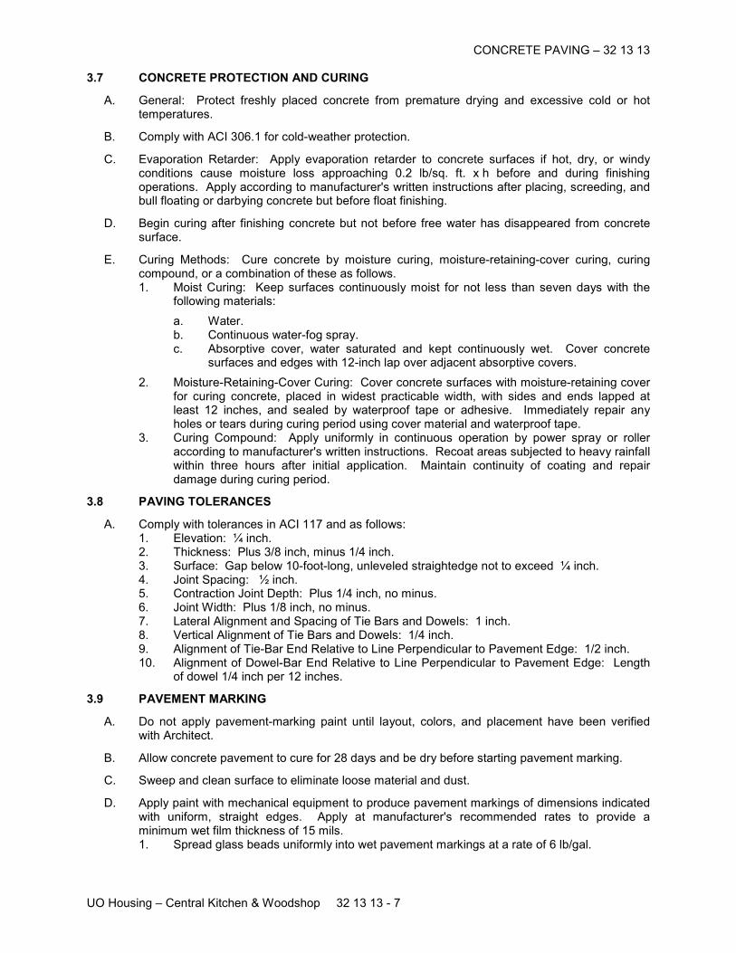
CONCRETE PAVING – 32 13 13
UO Housing – Central Kitchen & Woodshop 32 13 13 - 7
3.7 CONCRETE PROTECTION AND CURING
A. General: Protect freshly placed concrete from premature drying and excessive cold or hot temperatures.
B. Comply with ACI 306.1 for cold-weather protection.
C. Evaporation Retarder: Apply evaporation retarder to concrete surfaces if hot, dry, or windy conditions cause moisture loss approaching 0.2 lb/sq. ft. x h before and during finishing operations. Apply according to manufacturer's written instructions after placing, screeding, and bull floating or darbying concrete but before float finishing.
D. Begin curing after finishing concrete but not before free water has disappeared from concrete surface.
E. Curing Methods: Cure concrete by moisture curing, moisture-retaining-cover curing, curing compound, or a combination of these as follows. 1. Moist Curing: Keep surfaces continuously moist for not less than seven days with the
following materials:
a. Water. b. Continuous water-fog spray. c. Absorptive cover, water saturated and kept continuously wet. Cover concrete
surfaces and edges with 12-inch lap over adjacent absorptive covers.
2. Moisture-Retaining-Cover Curing: Cover concrete surfaces with moisture-retaining cover for curing concrete, placed in widest practicable width, with sides and ends lapped at least 12 inches, and sealed by waterproof tape or adhesive. Immediately repair any holes or tears during curing period using cover material and waterproof tape.
3. Curing Compound: Apply uniformly in continuous operation by power spray or roller according to manufacturer's written instructions. Recoat areas subjected to heavy rainfall within three hours after initial application. Maintain continuity of coating and repair damage during curing period.
3.8 PAVING TOLERANCES
A. Comply with tolerances in ACI 117 and as follows: 1. Elevation: ¼ inch. 2. Thickness: Plus 3/8 inch, minus 1/4 inch. 3. Surface: Gap below 10-foot-long, unleveled straightedge not to exceed ¼ inch. 4. Joint Spacing: ½ inch. 5. Contraction Joint Depth: Plus 1/4 inch, no minus. 6. Joint Width: Plus 1/8 inch, no minus. 7. Lateral Alignment and Spacing of Tie Bars and Dowels: 1 inch. 8. Vertical Alignment of Tie Bars and Dowels: 1/4 inch. 9. Alignment of Tie-Bar End Relative to Line Perpendicular to Pavement Edge: 1/2 inch. 10. Alignment of Dowel-Bar End Relative to Line Perpendicular to Pavement Edge: Length
of dowel 1/4 inch per 12 inches.
3.9 PAVEMENT MARKING
A. Do not apply pavement-marking paint until layout, colors, and placement have been verified with Architect.
B. Allow concrete pavement to cure for 28 days and be dry before starting pavement marking.
C. Sweep and clean surface to eliminate loose material and dust.
D. Apply paint with mechanical equipment to produce pavement markings of dimensions indicated with uniform, straight edges. Apply at manufacturer's recommended rates to provide a minimum wet film thickness of 15 mils. 1. Spread glass beads uniformly into wet pavement markings at a rate of 6 lb/gal.

CONCRETE PAVING – 32 13 13
UO Housing – Central Kitchen & Woodshop 32 13 13 - 8
3.10 WHEEL STOPS
A. Securely attach wheel stops to paving with not less than two galvanized-steel dowels located at one-quarter to one-third points. Firmly bond each dowel to wheel stop and to pavement. Securely install dowels in drilled holes in the paving and bond dowels to wheel stop. Recess head of dowel beneath top of wheel stop.
3.11 FIELD QUALITY CONTROL
A. Testing Agency: Engage a qualified independent testing and inspecting agency to perform field tests and inspections and prepare test reports.
B. Testing Services: Testing of composite samples of fresh concrete obtained according to ASTM C 172 shall be performed according to the following requirements: 1. Testing Frequency: Obtain at least 1 composite sample for each 100 cu. yd. or fraction
thereof of each concrete mix placed each day.
a. When frequency of testing will provide fewer than five compressive-strength tests for each concrete mixture, testing shall be conducted from at least five randomly selected batches or from each batch if fewer than five are used.
2. Slump: ASTM C 143/C 143M; one test at point of placement for each composite sample, but not less than one test for each day's pour of each concrete mix. Perform additional tests when concrete consistency appears to change.
3. Air Content: ASTM C 231, pressure method; one test for each composite sample, but not less than one test for each day's pour of each concrete mix.
4. Concrete Temperature: ASTM C 1064; one test hourly when air temperature is 40 deg F and below and when 80 deg F and above, and one test for each composite sample.
5. Compression Test Specimens: ASTM C 31/C 31M; cast and laboratory cure one set of three standard cylinder specimens for each composite sample.
6. Compressive-Strength Tests: ASTM C 39/C 39M; test 1 specimen at 7 days and 2 specimens at 28 days.
a. A compressive-strength test shall be the average compressive strength from 2 specimens obtained from same composite sample and tested at 28 days.
C. Strength of each concrete mix will be satisfactory if average of any 3 consecutive compressive-strength tests equals or exceeds specified compressive strength and no compressive-strength test value falls below specified compressive strength by more than 500 psi.
D. Test results shall be reported in writing to Architect, concrete manufacturer, and Contractor within 48 hours of testing. Reports of compressive-strength tests shall contain Project identification name and number, date of concrete placement, name of concrete testing and inspecting agency, location of concrete batch in Work, design compressive strength at 28 days, concrete mixture proportions and materials, compressive breaking strength, and type of break for both 7- and 28-day tests.
E. Nondestructive Testing: Impact hammer, sonoscope, or other nondestructive device may be permitted by Architect but will not be used as sole basis for approval or rejection of concrete.
F. Additional Tests: Testing and inspecting agency shall make additional tests of concrete when test results indicate that slump, air entrainment, compressive strengths, or other requirements have not been met, as directed by Architect.
G. Remove and replace concrete pavement where test results indicate that it does not comply with specified requirements.
H. Additional testing and inspecting, at Contractor's expense, will be performed to determine compliance of replaced or additional work with specified requirements.
CONCRETE PAVING – 32 13 13
UO Housing – Central Kitchen & Woodshop 32 13 13 - 9
3.12 REPAIRS AND PROTECTION
A. Remove and replace concrete paving that is broken, damaged, or defective or that does not comply with requirements in this Section. Remove work in complete sections from joint to joint unless otherwise approved by Architect.
B. Drill test cores, where directed by Architect, when necessary to determine magnitude of cracks or defective areas. Fill drilled core holes in satisfactory pavement areas with portland cement concrete bonded to pavement with epoxy adhesive.
C. Protect concrete paving from damage. Exclude traffic from paving for at least 14 days after placement. When construction traffic is permitted, maintain paving as clean as possible by removing surface stains and spillage of materials as they occur.
D. Maintain concrete paving free of stains, discoloration, dirt, and other foreign material. Sweep paving not more than two days before date scheduled for Substantial Completion inspections.
END OF SECTION
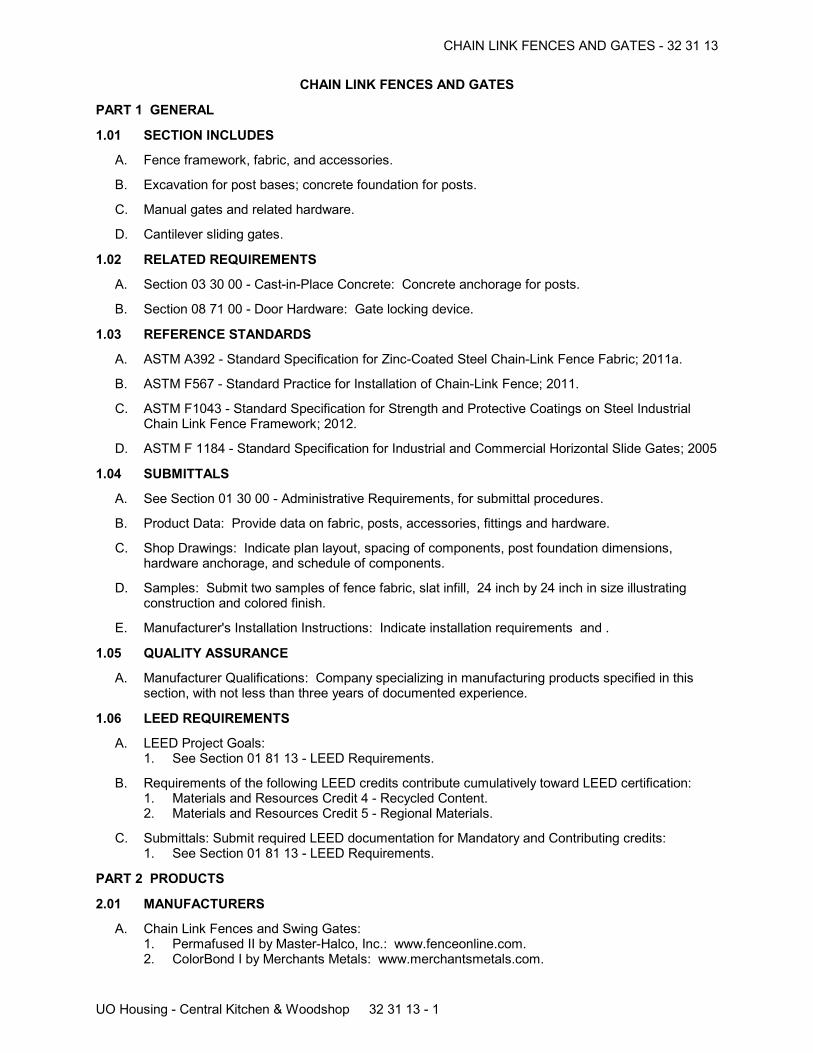
CHAIN LINK FENCES AND GATES - 32 31 13
UO Housing - Central Kitchen & Woodshop 32 31 13 - 1
CHAIN LINK FENCES AND GATES
PART 1 GENERAL
1.01 SECTION INCLUDES
A. Fence framework, fabric, and accessories.
B. Excavation for post bases; concrete foundation for posts.
C. Manual gates and related hardware.
D. Cantilever sliding gates.
1.02 RELATED REQUIREMENTS
A. Section 03 30 00 - Cast-in-Place Concrete: Concrete anchorage for posts.
B. Section 08 71 00 - Door Hardware: Gate locking device.
1.03 REFERENCE STANDARDS
A. ASTM A392 - Standard Specification for Zinc-Coated Steel Chain-Link Fence Fabric; 2011a.
B. ASTM F567 - Standard Practice for Installation of Chain-Link Fence; 2011.
C. ASTM F1043 - Standard Specification for Strength and Protective Coatings on Steel IndustrialChain Link Fence Framework; 2012.
D. ASTM F 1184 - Standard Specification for Industrial and Commercial Horizontal Slide Gates; 2005
1.04 SUBMITTALS
A. See Section 01 30 00 - Administrative Requirements, for submittal procedures.
B. Product Data: Provide data on fabric, posts, accessories, fittings and hardware.
C. Shop Drawings: Indicate plan layout, spacing of components, post foundation dimensions,hardware anchorage, and schedule of components.
D. Samples: Submit two samples of fence fabric, slat infill, 24 inch by 24 inch in size illustratingconstruction and colored finish.
E. Manufacturer's Installation Instructions: Indicate installation requirements and .
1.05 QUALITY ASSURANCE
A. Manufacturer Qualifications: Company specializing in manufacturing products specified in thissection, with not less than three years of documented experience.
1.06 LEED REQUIREMENTS
A. LEED Project Goals:1. See Section 01 81 13 - LEED Requirements.
B. Requirements of the following LEED credits contribute cumulatively toward LEED certification:1. Materials and Resources Credit 4 - Recycled Content.2. Materials and Resources Credit 5 - Regional Materials.
C. Submittals: Submit required LEED documentation for Mandatory and Contributing credits:1. See Section 01 81 13 - LEED Requirements.
PART 2 PRODUCTS
2.01 MANUFACTURERS
A. Chain Link Fences and Swing Gates:1. Permafused II by Master-Halco, Inc.: www.fenceonline.com.2. ColorBond I by Merchants Metals: www.merchantsmetals.com.
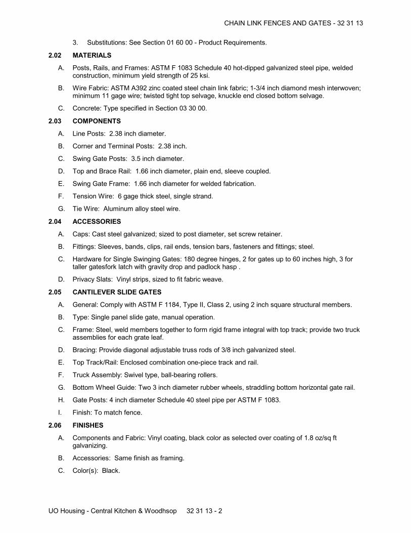
CHAIN LINK FENCES AND GATES - 32 31 13
UO Housing - Central Kitchen & Woodhsop 32 31 13 - 2
3. Substitutions: See Section 01 60 00 - Product Requirements.
2.02 MATERIALS
A. Posts, Rails, and Frames: ASTM F 1083 Schedule 40 hot-dipped galvanized steel pipe, weldedconstruction, minimum yield strength of 25 ksi.
B. Wire Fabric: ASTM A392 zinc coated steel chain link fabric; 1-3/4 inch diamond mesh interwoven;minimum 11 gage wire; twisted tight top selvage, knuckle end closed bottom selvage.
C. Concrete: Type specified in Section 03 30 00.
2.03 COMPONENTS
A. Line Posts: 2.38 inch diameter.
B. Corner and Terminal Posts: 2.38 inch.
C. Swing Gate Posts: 3.5 inch diameter.
D. Top and Brace Rail: 1.66 inch diameter, plain end, sleeve coupled.
E. Swing Gate Frame: 1.66 inch diameter for welded fabrication.
F. Tension Wire: 6 gage thick steel, single strand.
G. Tie Wire: Aluminum alloy steel wire.
2.04 ACCESSORIES
A. Caps: Cast steel galvanized; sized to post diameter, set screw retainer.
B. Fittings: Sleeves, bands, clips, rail ends, tension bars, fasteners and fittings; steel.
C. Hardware for Single Swinging Gates: 180 degree hinges, 2 for gates up to 60 inches high, 3 fortaller gatesfork latch with gravity drop and padlock hasp .
D. Privacy Slats: Vinyl strips, sized to fit fabric weave.
2.05 CANTILEVER SLIDE GATES
A. General: Comply with ASTM F 1184, Type II, Class 2, using 2 inch square structural members.
B. Type: Single panel slide gate, manual operation.
C. Frame: Steel, weld members together to form rigid frame integral with top track; provide two truckassemblies for each grate leaf.
D. Bracing: Provide diagonal adjustable truss rods of 3/8 inch galvanized steel.
E. Top Track/Rail: Enclosed combination one-piece track and rail.
F. Truck Assembly: Swivel type, ball-bearing rollers.
G. Bottom Wheel Guide: Two 3 inch diameter rubber wheels, straddling bottom horizontal gate rail.
H. Gate Posts: 4 inch diameter Schedule 40 steel pipe per ASTM F 1083.
I. Finish: To match fence.
2.06 FINISHES
A. Components and Fabric: Vinyl coating, black color as selected over coating of 1.8 oz/sq ftgalvanizing.
B. Accessories: Same finish as framing.
C. Color(s): Black.
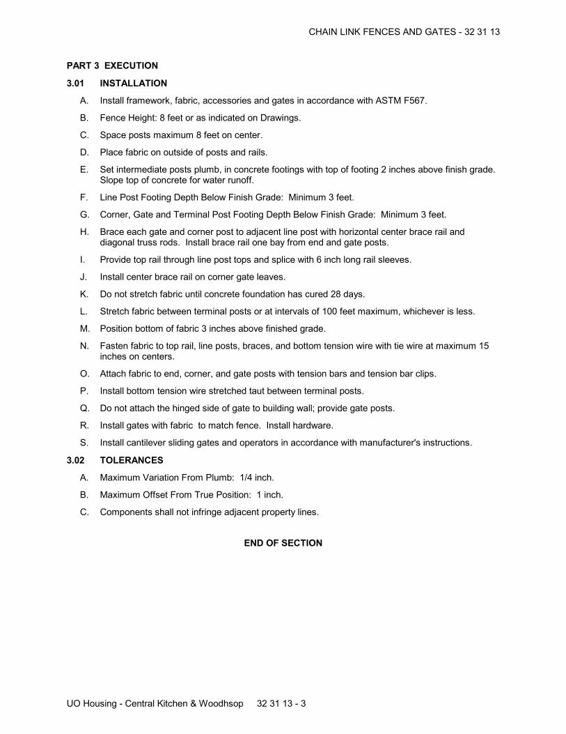
CHAIN LINK FENCES AND GATES - 32 31 13
UO Housing - Central Kitchen & Woodhsop 32 31 13 - 3
PART 3 EXECUTION
3.01 INSTALLATION
A. Install framework, fabric, accessories and gates in accordance with ASTM F567.
B. Fence Height: 8 feet or as indicated on Drawings.
C. Space posts maximum 8 feet on center.
D. Place fabric on outside of posts and rails.
E. Set intermediate posts plumb, in concrete footings with top of footing 2 inches above finish grade.Slope top of concrete for water runoff.
F. Line Post Footing Depth Below Finish Grade: Minimum 3 feet.
G. Corner, Gate and Terminal Post Footing Depth Below Finish Grade: Minimum 3 feet.
H. Brace each gate and corner post to adjacent line post with horizontal center brace rail anddiagonal truss rods. Install brace rail one bay from end and gate posts.
I. Provide top rail through line post tops and splice with 6 inch long rail sleeves.
J. Install center brace rail on corner gate leaves.
K. Do not stretch fabric until concrete foundation has cured 28 days.
L. Stretch fabric between terminal posts or at intervals of 100 feet maximum, whichever is less.
M. Position bottom of fabric 3 inches above finished grade.
N. Fasten fabric to top rail, line posts, braces, and bottom tension wire with tie wire at maximum 15inches on centers.
O. Attach fabric to end, corner, and gate posts with tension bars and tension bar clips.
P. Install bottom tension wire stretched taut between terminal posts.
Q. Do not attach the hinged side of gate to building wall; provide gate posts.
R. Install gates with fabric to match fence. Install hardware.
S. Install cantilever sliding gates and operators in accordance with manufacturer's instructions.
3.02 TOLERANCES
A. Maximum Variation From Plumb: 1/4 inch.
B. Maximum Offset From True Position: 1 inch.
C. Components shall not infringe adjacent property lines.
END OF SECTION
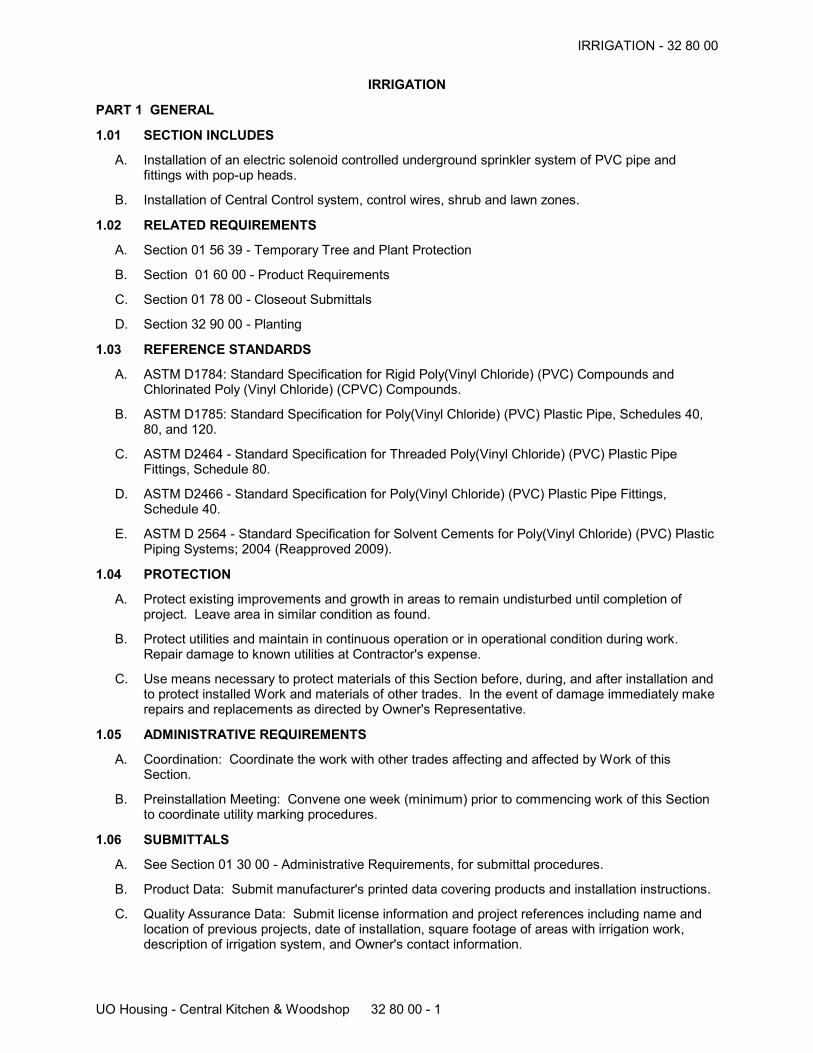
IRRIGATION - 32 80 00
UO Housing - Central Kitchen & Woodshop 32 80 00 - 1
IRRIGATION
PART 1 GENERAL
1.01 SECTION INCLUDES
A. Installation of an electric solenoid controlled underground sprinkler system of PVC pipe andfittings with pop-up heads.
B. Installation of Central Control system, control wires, shrub and lawn zones.
1.02 RELATED REQUIREMENTS
A. Section 01 56 39 - Temporary Tree and Plant Protection
B. Section 01 60 00 - Product Requirements
C. Section 01 78 00 - Closeout Submittals
D. Section 32 90 00 - Planting
1.03 REFERENCE STANDARDS
A. ASTM D1784: Standard Specification for Rigid Poly(Vinyl Chloride) (PVC) Compounds andChlorinated Poly (Vinyl Chloride) (CPVC) Compounds.
B. ASTM D1785: Standard Specification for Poly(Vinyl Chloride) (PVC) Plastic Pipe, Schedules 40,80, and 120.
C. ASTM D2464 - Standard Specification for Threaded Poly(Vinyl Chloride) (PVC) Plastic PipeFittings, Schedule 80.
D. ASTM D2466 - Standard Specification for Poly(Vinyl Chloride) (PVC) Plastic Pipe Fittings,Schedule 40.
E. ASTM D 2564 - Standard Specification for Solvent Cements for Poly(Vinyl Chloride) (PVC) PlasticPiping Systems; 2004 (Reapproved 2009).
1.04 PROTECTION
A. Protect existing improvements and growth in areas to remain undisturbed until completion ofproject. Leave area in similar condition as found.
B. Protect utilities and maintain in continuous operation or in operational condition during work.Repair damage to known utilities at Contractor's expense.
C. Use means necessary to protect materials of this Section before, during, and after installation andto protect installed Work and materials of other trades. In the event of damage immediately makerepairs and replacements as directed by Owner's Representative.
1.05 ADMINISTRATIVE REQUIREMENTS
A. Coordination: Coordinate the work with other trades affecting and affected by Work of thisSection.
B. Preinstallation Meeting: Convene one week (minimum) prior to commencing work of this Sectionto coordinate utility marking procedures.
1.06 SUBMITTALS
A. See Section 01 30 00 - Administrative Requirements, for submittal procedures.
B. Product Data: Submit manufacturer's printed data covering products and installation instructions.
C. Quality Assurance Data: Submit license information and project references including name andlocation of previous projects, date of installation, square footage of areas with irrigation work,description of irrigation system, and Owner's contact information.
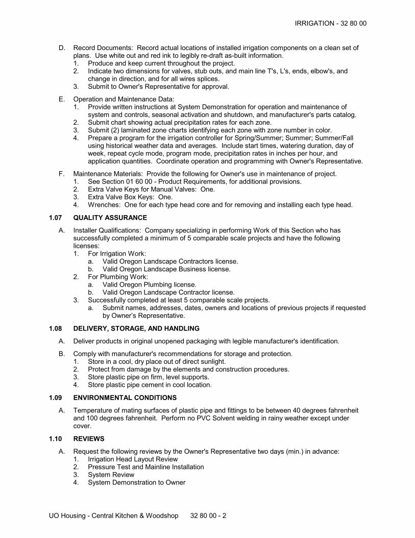
IRRIGATION - 32 80 00
UO Housing - Central Kitchen & Woodshop 32 80 00 - 2
D. Record Documents: Record actual locations of installed irrigation components on a clean set ofplans. Use white out and red ink to legibly re-draft as-built information.1. Produce and keep current throughout the project.2. Indicate two dimensions for valves, stub outs, and main line T's, L's, ends, elbow's, and
change in direction, and for all wires splices.3. Submit to Owner's Representative for approval.
E. Operation and Maintenance Data:1. Provide written instructions at System Demonstration for operation and maintenance of
system and controls, seasonal activation and shutdown, and manufacturer's parts catalog.2. Submit chart showing actual precipitation rates for each zone.3. Submit (2) laminated zone charts identifying each zone with zone number in color.4. Prepare a program for the irrigation controller for Spring/Summer; Summer; Summer/Fall
using historical weather data and averages. Include start times, watering duration, day ofweek, repeat cycle mode, program mode, precipitation rates in inches per hour, andapplication quantities. Coordinate operation and programming with Owner's Representative.
F. Maintenance Materials: Provide the following for Owner's use in maintenance of project.1. See Section 01 60 00 - Product Requirements, for additional provisions.2. Extra Valve Keys for Manual Valves: One.3. Extra Valve Box Keys: One.4. Wrenches: One for each type head core and for removing and installing each type head.
1.07 QUALITY ASSURANCE
A. Installer Qualifications: Company specializing in performing Work of this Section who hassuccessfully completed a minimum of 5 comparable scale projects and have the followinglicenses:1. For Irrigation Work:
a. Valid Oregon Landscape Contractors license.b. Valid Oregon Landscape Business license.
2. For Plumbing Work:a. Valid Oregon Plumbing license.b. Valid Oregon Landscape Contractor license.
3. Successfully completed at least 5 comparable scale projects.a. Submit names, addresses, dates, owners and locations of previous projects if requested
by Owner’s Representative.
1.08 DELIVERY, STORAGE, AND HANDLING
A. Deliver products in original unopened packaging with legible manufacturer's identification.
B. Comply with manufacturer's recommendations for storage and protection.1. Store in a cool, dry place out of direct sunlight.2. Protect from damage by the elements and construction procedures.3. Store plastic pipe on firm, level supports.4. Store plastic pipe cement in cool location.
1.09 ENVIRONMENTAL CONDITIONS
A. Temperature of mating surfaces of plastic pipe and fittings to be between 40 degrees fahrenheitand 100 degrees fahrenheit. Perform no PVC Solvent welding in rainy weather except undercover.
1.10 REVIEWS
A. Request the following reviews by the Owner's Representative two days (min.) in advance:1. Irrigation Head Layout Review2. Pressure Test and Mainline Installation3. System Review4. System Demonstration to Owner
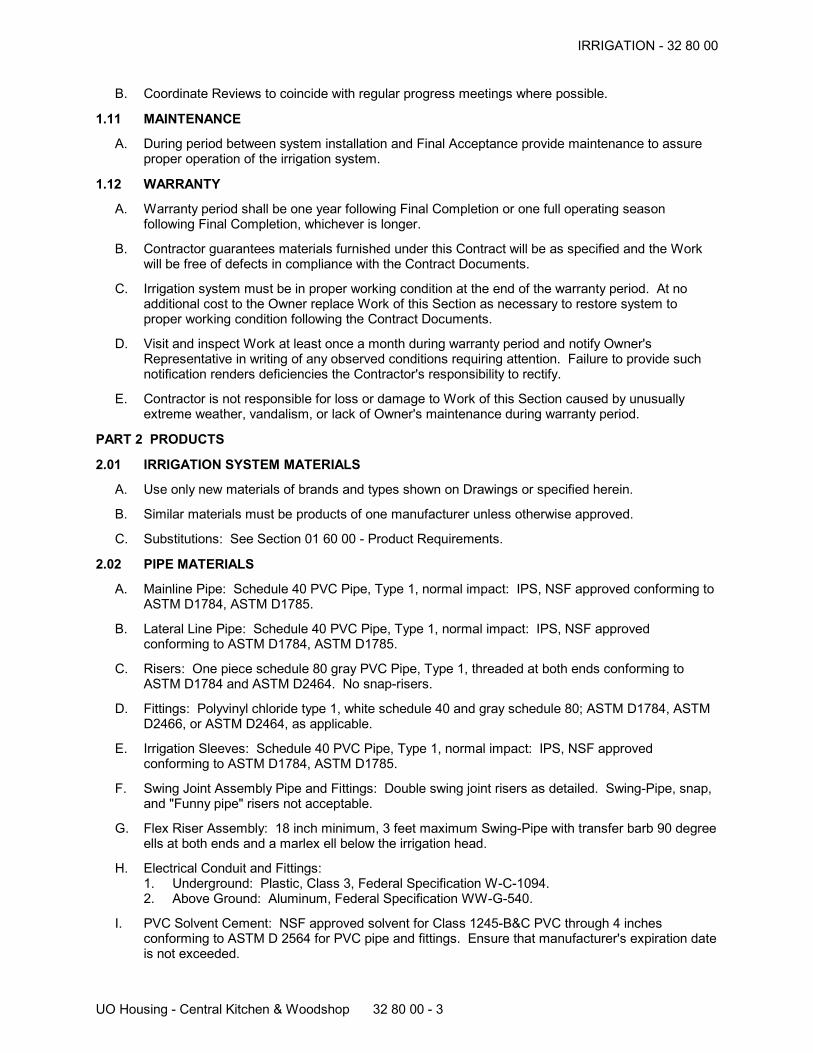
IRRIGATION - 32 80 00
UO Housing - Central Kitchen & Woodshop 32 80 00 - 3
B. Coordinate Reviews to coincide with regular progress meetings where possible.
1.11 MAINTENANCE
A. During period between system installation and Final Acceptance provide maintenance to assureproper operation of the irrigation system.
1.12 WARRANTY
A. Warranty period shall be one year following Final Completion or one full operating seasonfollowing Final Completion, whichever is longer.
B. Contractor guarantees materials furnished under this Contract will be as specified and the Workwill be free of defects in compliance with the Contract Documents.
C. Irrigation system must be in proper working condition at the end of the warranty period. At noadditional cost to the Owner replace Work of this Section as necessary to restore system toproper working condition following the Contract Documents.
D. Visit and inspect Work at least once a month during warranty period and notify Owner'sRepresentative in writing of any observed conditions requiring attention. Failure to provide suchnotification renders deficiencies the Contractor's responsibility to rectify.
E. Contractor is not responsible for loss or damage to Work of this Section caused by unusuallyextreme weather, vandalism, or lack of Owner's maintenance during warranty period.
PART 2 PRODUCTS
2.01 IRRIGATION SYSTEM MATERIALS
A. Use only new materials of brands and types shown on Drawings or specified herein.
B. Similar materials must be products of one manufacturer unless otherwise approved.
C. Substitutions: See Section 01 60 00 - Product Requirements.
2.02 PIPE MATERIALS
A. Mainline Pipe: Schedule 40 PVC Pipe, Type 1, normal impact: IPS, NSF approved conforming toASTM D1784, ASTM D1785.
B. Lateral Line Pipe: Schedule 40 PVC Pipe, Type 1, normal impact: IPS, NSF approvedconforming to ASTM D1784, ASTM D1785.
C. Risers: One piece schedule 80 gray PVC Pipe, Type 1, threaded at both ends conforming toASTM D1784 and ASTM D2464. No snap-risers.
D. Fittings: Polyvinyl chloride type 1, white schedule 40 and gray schedule 80; ASTM D1784, ASTMD2466, or ASTM D2464, as applicable.
E. Irrigation Sleeves: Schedule 40 PVC Pipe, Type 1, normal impact: IPS, NSF approvedconforming to ASTM D1784, ASTM D1785.
F. Swing Joint Assembly Pipe and Fittings: Double swing joint risers as detailed. Swing-Pipe, snap,and "Funny pipe" risers not acceptable.
G. Flex Riser Assembly: 18 inch minimum, 3 feet maximum Swing-Pipe with transfer barb 90 degreeells at both ends and a marlex ell below the irrigation head.
H. Electrical Conduit and Fittings:1. Underground: Plastic, Class 3, Federal Specification W-C-1094.2. Above Ground: Aluminum, Federal Specification WW-G-540.
I. PVC Solvent Cement: NSF approved solvent for Class 1245-B&C PVC through 4 inchesconforming to ASTM D 2564 for PVC pipe and fittings. Ensure that manufacturer's expiration dateis not exceeded.
IRRIGATION - 32 80 00
UO Housing - Central Kitchen & Woodshop 32 80 00 - 4
1. At main lines: IPS Corporation Weld-On #705 PVC.2. At lateral lines: IPS Corporation Weld-On #705 PVC or #721 PVC.
J. PVC Cleaner and Primer: Oatey Lo-V.O.C. Purple Primer #31903.
2.03 VALVES
A. Isolation Valves - 3 inch and under: Threaded gate valve with resilient wedge sized to matchmainline with wheel handle.1. Approved Products:
a. Kennedy model 8057, or approved.
B. Control Valve Assembly:1. Automatic Control Valve: Globe type, 200 psi rated, threaded connections with cross type
operating handle designed to receive operating key. Size according to Valve Schedule onDrawing.a. For Irrigation Zones less than 5 GPM:
1) Irritrol Model 700-1, or approved.2) Include Irritrol Omnireg Pressure Regulator Model OMR-100 (pressure regulating
system).b. For Irrigation Zones larger than 5 GPM:
1) Toro P-220 Series, or approved.2) Include EZ Reg (pressure regulating system).
C. Quick Coupling Valves:1. Approved Products:
a. Rain Bird 44 RC, or approved.
D. Manual Drain Valve: Globe or angle brass manual valve with non-floating seat disk that allowspositive drainage.1. Approved Products:
a. Manufactured by Champion, or approved.
E. Backflow Preventers: Double check valve assembly.1. Approved Products:
a. Size: 2 inch.b. Model # DC4A-118-T2 by Apollo.
2.04 VALVE BOXES
A. Valve box of suitable size with tee top type lid .1. Green box and lid.
B. Install valves in the following valve boxes:1. Control Valve Assembly: (2) Carson 1419-12, T-Lid, or approved.2. Quick Coupling, Manual Drain, and Isolation Valves: Carson 910-10, T-Lid, or approved.3. Other Valves: Sized as applicable by Carson, or approved.
2.05 IRRIGATION HEADS
A. Makes and models shown on Drawings, or approved.
2.06 WIRE
A. Zone Control Wire: Install according to manufacturer's wire schedule for valve specifications. 14gauge minimum, type AVG-UF, bearing U.S. approval.
B. Wire Connections: Direct bury splice Kit.1. DBR/Y by 3M.2. Scotch Lok 3570.3. Substitutions: See Section 01 60 00 - Product Requirements.
C. Utility Locate Wire: 14 gauge minimum, type AVG-UF, bearing U.S. approval, blue in color.
IRRIGATION - 32 80 00
UO Housing - Central Kitchen & Woodshop 32 80 00 - 5
2.07 IRRIGATION CONTROLLER
A. Wall mount control assembly in metal cabinet.1. Size: 24 Stations2. Enclosure: Stainless steel wall mount (large).3. Manufacturer/Model number: Toro TCM-424E-ID, or approved.
B. Contact: HD Fowler: 541-607-0081.
C. Substitutions: See Section 01 60 00 - Product Requirements.
2.08 BACKFILL MATERIALS
A. Pea Gravel: 3/4 x 1/2 inch washed round rock.
B. Sand: Clean, fill sand free of clay, rocks, organic matter, or other deleterious material.
C. Topsoil or Loam: See Section 32 90 00 - Planting.
PART 3 EXECUTION
3.01 EXAMINATION
A. Verify that required utilities and sleeves are available, in proper location, and ready for use. Verifylocation, type, size, psi, and GPM of existing water lines, meters, and sleeves.
B. Verify that surfaces and structures to receive Work are accurately sized and located, sound,secure, true, complete, and otherwise properly prepared.
C. Verify electrical service and conduit for Irrigation Controller is properly sized and located.
3.02 PREPARATION
A. System layout is diagrammatic. Route piping to avoid plants, ground cover, and structures. Iffield measurements differ slightly from Drawings modify work for accurate fit. If measurementsdiffer substantially notify Owner's Representative prior to installation.
B. Review layout requirements with other affected work. Coordinate locations of sleeves underpaving to accommodate system and piping to minimize conflict with other work.
C. Coordinate connections to existing irrigation system, including system shut down, newconnections, system re-start, and scheduling of new irrigation zone run times with Owner'sRepresentative.
D. Irrigation Head Layout Review: Install flags at locations of irrigation heads and componentsshown on Drawings. Obtain Owner's Representative's approval and make adjustments tolocations as directed. Coordinate marking of pipe trenches and location of valves prior toexecuting Work.
3.03 CUTTING OF PAVEMENT AND REPAIR
A. Do no cutting of pavement for installation of Work without Owner Representative's approval.
3.04 MASTER VALVE AND FLOW SENSOR INSTALLATION
A. Install where shown on Drawings in accordance with manufacturer's directions when makingsupply and central control component connections.
3.05 TRENCHING
A. Excavate trenches with uniform bottom and remove rocks and sharp objects to provide firm, even,clean base for pipe. Width of trench to be 1.5 times the outside diameter of the pipe.
B. Trench Depth:1. Minimum Cover over Installed Mainline Piping: 18 inches.2. Minimum Cover over Installed Lateral Line Piping: 12 inches.

IRRIGATION - 32 80 00
UO Housing - Central Kitchen & Woodshop 32 80 00 - 6
3. Minimum Cover over Installed Sleeves in Roadway: 24 inches.4. Minimum Cover over Installed Sleeves at other paving: 6 inches from bottom of paving.
C. More than one pipe is permitted in the same trench provided that:1. Two pipes may be stacked vertically if 4 inches of Sand separates them.2. Three or more pipes must be laid 4 inches apart horizontally.
D. Where excavation is performed to excess levels backfill with Sand to proper levels.
E. Keep trenches dry and frost free. Provide and operate pumping equipment to keep excavationsfree from standing water.
F. Protect existing vegetation to remain. Cut no roots over two inches in diameter without approvalof Owner's Representative. Make cuts clean, straight, at right angles to roots. Paint cuts over1-1/2 inches diameter with approved tree paint. Repair or replace damaged plant material.
3.06 SLEEVE INSTALLATION
A. Sleeves may be jacked or pulled but cover requirements must be maintained. Jacking of PVCpipe is not permitted in rocky or bar run fills where there is potential for damage to pipes.
B. Extend sleeves 12 inches beyond pavement edge or curb.
C. Install level and perpendicular to sidewalks and pavement unless shown otherwise on drawings.
D. Provide markers where sleeve ends are concealed.
3.07 PIPE BEDDING
A. Mainline: Provide uniform bearing surface of Sand, 4 inches minimum depth, free of rocks andsharp objects under entire length of pipe.
B. Lateral Line: Provide uniform bearing surface of clean topsoil, loam, or Sand. If rock or otherdeleterious materials are encountered bed pipe with 4 inches of Sand on all sides.
3.08 PIPE INSTALLATION
A. Irrigation lines may be jacked or pulled but cover requirements must be maintained. Jacking ofPVC pipe is not permitted in rocky or bar run fill or where there is potential damage to pipes.
B. Install pipe in accordance with manufacturer's instructions and with the following minimumclearances around pipe:1. 2 inch diameter and smaller: 2 inches2. 2-1/2 inch diameter and larger: 4 inches3. Between irrigation and other utilities: 1 foot
C. Threaded Plastic Pipe Installation:1. Do not use solvent cement on joints.2. Wrap threaded joints with teflon tape. Minimum 4 wraps of tape.
D. Cemented Plastic Pipe Installation:1. Cut ends square using approved pipe cutter and bevel cuts with deburring tool.2. Clean pipe of scale, sand, dirt, etc. prior to assembling.3. Avoid using an excess amount of primer and cement when making joints; particularly on the
inside of female pipe ends and fittings.4. Wipe off excess cement continuously as it appears on the surface of the pipe after making
joints.5. Allow fifteen minutes of cure time on joints before moving or handling. Assemble pipe before
lowering into trench.6. Snake lines to allow for contraction.7. Transition pipe sizes at fittings and not bell end of pipes.8. Install thrust blocks at 90 degree corners and tees.
IRRIGATION - 32 80 00
UO Housing - Central Kitchen & Woodshop 32 80 00 - 7
3.09 THRUST BLOCK INSTALLATION
A. Install 2500psi thrust block at pipe corners, tees, ells, and stub outs.1. Pipe 2 - 3 inches in diameter: 1 cubic foot.
3.10 VALVE INSTALLATION
A. Install plumb and square, as detailed, and according to manufacturer's specifications.
B. Manual Drain Valves:1. Install at mainline low points and at outlet of control valves where laterals run uphill.2. Record locations on as-built drawings.
C. Install 1 valve in each valve box assembly.
D. Valve Sump: Install a minimum of 2 cubic feet of Pea Gravel below each valve. Allow for 4inches clearance between bottom of valve and valve sump.
3.11 VALVE BOX INSTALLATION
A. Install plumb and square with adjacent construction with one valve in each valve box assembly.
B. At Control Valve Assemblies bolt two valve boxes together as detailed.
C. Permanently label valve type and zone number on inside of valve box lid.
D. Set top of valve boxes flush with lawn or mulch at plant beds unless otherwise noted.
E. Provide 12 square inches (min.) of support on each side of valve box as detailed.
3.12 CONTROL WIRE INSTALLATION
A. Install wires below irrigation mainline with multiple wires bundled together at 5 foot maximumintervals in a continuous run. Use coded and labeled wires for each valve. Notify Owner'sRepresentative for approval prior if splices are required and locate in valve box.
B. Provide 48 inches loop in wires at each valve where controls are connected and at 100 footmaximum intervals between. Coil wire around 1/2 inch rebar dowel inside of valve box.
C. Make electrical joints waterproof using specified connectors. Enclose joints in valve boxes.
D. Install wire in continuous runs with no splices unless approved.
E. Show wire routes and approved splice locations on As-Built drawings.
F. Install wires above grade or independent of the mainline in conduit.
3.13 CENTRAL CONTROL COMMUNICATION WIRE INSTALLATION
A. Install continuous run of communication wire from Master Valve to Irrigation Controller. Followsame installation procedures as Control Wire Installation. No splicing of wire is permitted.
B. Install (2) yellow Control Wires from controller to master valve in a single, unspliced length.
3.14 IRRIGATION CONTROL ASSEMBLY INSTALLATION
A. Install Irrigation Control Assembly in accordance with manufacturer's specifications and applicablecodes. Connect to 120V power supply at location shown on drawings and by Owner'sRepresentative.
3.15 MAINLINE PRESSURE TEST AND INSPECTION
A. Field inspection and testing will be performed under provisions of Section 01 40 00.
B. Prior to backfilling and installing valves test irrigation mainline for leakage. Establish and maintain100 psi pressure for 24 hours. Perform test a minimum of 24 hours after set-up of solvent weld.
IRRIGATION - 32 80 00
UO Housing - Central Kitchen & Woodshop 32 80 00 - 8
Notify Owner's Representative a minimum of 24 hours for review of pressure gauge at beginning andend of test period. Mainline will be accepted if pressure loss is less than 2 psi.
C. Following the pressure test but prior to backfilling, notify Owner's Representative for review ofpipe, fittings, joints, thrust blocks, bedding, control wire installation, valves, and other materials forinstallation and water tightness.
D. After successful pressure test and mainline inspection begin backfilling and assembly of zonesand system components.
3.16 BACKFILLING
A. Remove debris, sharp rocks, and decayable matter from areas to be back filled beforeproceeding.
B. Main Lines: Provide 6 inch Sand cover over piping then place Utility Locate Wire the entire lengthof pipes where control wires are not present. Backfill remainder of trench with Topsoil or Loam.
C. Lateral Lines: Backfill trench with Topsoil or Loam. Protect piping from displacement.
D. At Paved Areas: Backfill trench with Sand under paved areas.
E. Compact backfill in 6 inch lifts to match density of surrounding material. Install backfill to matchadjacent elevations.
3.17 FLUSHING
A. Mainline: Open valves and thoroughly flush piping system under full water head after piping,risers, and valves are installed. Maintain flushing for three minutes. Close valves and cap risersimmediately after flushing.
B. Second Flushing: Flush a second time after installation of lateral lines and sprinklers prior tonozzle installation. Flush under full water head for three minutes. Install nozzles after flushing.
3.18 SPRINKLER HEAD INSTALLATION
A. Install plumb with top of Topsoil/Loam or Mulch as detailed and at locations shown on drawings.Allow a maximum of 3 inches clearance between sprinkler head and adjacent lawn or plantingedge.
B. Install 1 cubic foot Pea Gravel sump on all low irrigation heads where drainage occurs at zoneshutdown.
3.19 IRRIGATION AUDIT
A. Coordinate Work with an independent Irrigation Auditor retained by the Facilities Services ProjectManager. The following results will be provided to the Contractor performing Work of this Sectionin a signed report by a certified irrigation auditor in good standing with the Irrigation Association(IA) and in accordance with the IA's Landscape Irrigation Auditor's Handbook.1. Distribution uniformity for zones2. Precipitation rates for zones3. Catch can test of each zone with a drawing showing catch can locations4. Flow rates, static, and dynamic pressures at each zone5. Sentinel data summary spreadsheet.
B. Coordinate scheduling of irrigation audit at plant beds with the Owner to occur prior to plantmaterial installation.
C. Provide Irrigation Auditor with marked up drawings, drawn at the original scale of the irrigationplan, showing as-built conditions including:1. station numbers and locations2. sprinkler locations and type3. nozzle type and size
IRRIGATION - 32 80 00
UO Housing - Central Kitchen & Woodshop 32 80 00 - 9
D. Adjust head types, spacing, nozzles, etc. at irrigation zones to achieve a minimum distributionuniformity of:1. 60% at fixed spray zones2. 70% at rotary zones
3.20 SYSTEM REVIEW
A. Prepare and start system in accordance with manufacturer's instructions. Prior to notifyingOwner's Representative for review of the system review zones and make adjustments to ensurefull and even coverage.
B. Notify Owner's Representative for review of system operation to determine if water afforded to allareas is complete, adequate, and uniform.
C. Adjust system for full water coverage as directed.
3.21 SYSTEM DEMONSTRATION TO OWNER
A. Instruct Owner's personnel in operation and maintenance of system, including adjusting ofsprinkler heads. Use operation and maintenance data as basis for demonstration.
3.22 CLEANING
A. Remove excess excavation, backfill materials, and other left over materials from the site. Cleanimprovements soiled by Work of this Section.
END OF SECTION
PLANTING - 32 90 00
UO Housing - Central Kitchen & Woodshop 32 90 00 - 1
PLANTING
PART 1 GENERAL
1.01 SECTION INCLUDES
A. Preparation of subsoil.
B. Soil Material placement.
C. New trees, plants, and ground cover.
D. Mulch and Fertilizer.
E. Maintenance.
1.02 RELATED REQUIREMENTS
A. Section 01 56 39 - Temporary Tree and Plant Protection.
B. Section 01 60 00 - Product Requirements.
C. Section 01 70 00 - Execution and Closeout Requirements.
D. Section 31 20 00 - Earth Moving.
E. Section 32 80 00 - Irrigation.
1.03 DEFINITIONS
A. Weeds: Any plant life not specified or scheduled. Includes seeds and roots.
B. Plants: Living trees, plants, and ground cover specified in this Section, and described in ANSIZ60.1.
1.04 REFERENCE STANDARDS
A. Quality definitions, grading tolerances, root system condition, caliper height, branching, budding:ANSI/ANLA Z60.1 - American Standard for Nursery Stock, latest edition.
B. ANSI A300 Part 1 - American National Standard for Tree Care Operations -- Tree, Shrub andOther Woody Plant Maintenance -- Standard Practices; 2001.
C. Nomenclature conforms to "Standardized Plant Names," 1942 Edition, published by J. HoraceMcFarland Co., or "New Sunset Western Garden Book," listed in these references are those usedmost commonly in the nursery trade.
1.05 PROTECTION
A. Protect existing improvements and growth in areas to remain undisturbed until completion ofproject. Leave in similar condition as found.
B. Maintain benchmarks, monuments, and other reference points. Replace if disturbed or destroyed.
C. Contact local utility companies for verification of the location of underground utilities within theproject area prior to starting excavation. Protect utilities and maintain in continuous operation orin operational condition during work. Repair damage to known utilities or related facilities in anapproved manner at Contractor's expense.
D. Protect drainage inlets and underground drain lines from infiltration or clogging by soils and mulchduring construction until Final Completion.
E. Protect materials of this Section before, during, and after installation. Protect installed work andmaterials of other trades. In the event of damage make repairs to like new condition. If productsare not repairable to like new condition provide replacement.
PLANTING - 32 90 00
UO Housing - Central Kitchen & Woodshop 32 90 00 - 2
1.06 SUBMITTALS
A. See Section 01 30 00 - Administrative Requirements, for submittal procedures.
B. Maintenance Data: Include written instructions covering yearly recommended maintenance andcare of plantings including fertilization, pest and disease control, weed control, mulching, andpruning.
C. Quality Assurance Data: Submit license information and project references including name andlocation of previous projects, date of installation, square footage of areas with planting work, andOwner's contact information.
D. Submit list of plant life sources within 14 calendar days of Agreement Date.1. Submit confirmation from supplier(s) that specified plant materials, meeting the
specifications, have been secured.2. Include plant name, quantity, size, condition, and name of supplier.
E. Product Data: Submit manufacturer's printed data for products and a list of suppliers.
F. Sample: Submit a 2 quart sample of Soil Material with supplier's name and specific location ofsource. Approval of Soil Material by Owner's Representative is required prior to delivery to thesite.
G. Invoices: Within 2 days of delivery submit invoices, load tickets, and truck measures for SoilMaterial, Organic Material, and Mulch. Landscape areas will not be accepted until invoices arereceived by Owner's Representative.
1.07 QUALITY ASSURANCE
A. Valid Oregon Landscape Contractor's license.
B. Valid Oregon Landscape Business license.
C. Herbicide applicators must have valid State of Oregon Herbicide Applicator's license.
D. Installer Qualifications: Company specializing in installing and planting the plants with 5 projectsof comparable scale successfully completed.1. Submit names, addresses, and dates of previous projects, owners.
1.08 COORDINATION
A. Coordinate with other trades affecting and affected by Work of this Section.
B. Pre-Installation Conference: Attend conference to coordinate Work of this Section and otherrelated Sections.
1.09 DELIVERY, STORAGE, AND HANDLING
A. Deliver fertilizer in waterproof bags showing weight, chemical analysis, and name ofmanufacturer.
B. Protect and maintain plant life until planted.
C. Deliver plant life materials immediately prior to placement. Keep plants moist.
D. Deliver products in original unopened packaging with legible manufacturer's identification.
E. Seed containers shall show manufacturer's guaranteed analysis of seed mixture, percentage ofpurity, year of production, date and location of packaging, name and trademark, and conformancewith governing regulations.
F. Plants may be rejected if:1. Ball of earth surrounding roots has been dried out, cracked, or broken.2. Burlap, staves, wire baskets, or ropes required in connection with transplanting have been
displaced.3. Grower or nursery identification labels have been displaced prior to acceptance.
PLANTING - 32 90 00
UO Housing - Central Kitchen & Woodshop 32 90 00 - 3
1.10 ENVIRONMENTAL CONDITIONS
A. Do not install plant life when ambient temperatures is below 32 degrees F or above 90 degrees F.
B. Do not install plant life when wind velocity exceeds 30 mph.
C. Do not install plant life when soil becomes saturated.
D. Install plant materials during periods which are normal for such work as determined by thefollowing:1. Biological season2. Specified environmental conditions3. Accepted practice4. After all major construction work has been completed
E. Planting Seasons:1. Trees: Bare root trees may be planted only between January 15th and March 15th unless
otherwise approved.2. Seeding: Permitted between April 15 and October 15 unless otherwise approved.3. Other: Permitted during any period, except when prohibited by other portions of this Section.
1.11 Reviews
A. Request the following reviews by the Owner's Representative a minimum of 2 days in advance:1. Subgrade preparation2. Soil Material placement3. Organic Material placement4. Finish grading5. Plant materials6. Plant material layout7. Planting mock-up8. Completion
B. See Part 3 - Execution for review requirements.
C. Coordinate all reviews to coincide with regular progress meetings where possible.
1.12 RECORD DOCUMENTS
A. See Section 01 78 00 - Closeout Submittals
B. Produce, keep current, and submit legible record documents on a clean set of plans and detailssupplied by the Owner's Representative. Use white-out and red ink to legibly re-draft actuallocations of installed work.
1.13 WARRANTY
A. See Section 01 78 00 - Closeout Submittals, for additional warranty requirements.
B. Provide one year warranty following Final Completion or one full growing season following FinalCompletion, whichever is later.
C. Replacements: Plants of same size and species as specified, planted in the next growing season,with a new warranty commencing on date of replacement.
D. Inspection: Visit work at least once a month during warranty period. Notify Owner'sRepresentative and Owner in writing of any observed conditions requiring attention. Failure toprovide such notification renders any deficiencies the Contractor's responsibility to rectify.
E. At the end of the warranty period, as directed by Owner's Representative and at no additional costto the Owner:1. Replace work not surviving, in poor condition, or not exhibiting satisfactory growth.2. Lawns must be healthy, dense, uniform, well sodded, and reasonably weed free as judged by
the Owner's Representative
PLANTING - 32 90 00
UO Housing - Central Kitchen & Woodshop 32 90 00 - 4
3. Reset plant materials which have settled or become un-set4. Replace plant materials which appear to be a different species or variety than specified.5. Provide noxious weed eradication from imported Soil Material, if required and as specified
herein.6. Complete warranty work within 30 days of warranty review.
F. Contractor is not responsible for plant loss or damage to work during warranty period which iscaused by unusually extreme weather, vandalism, or Owner's lack of maintenance.
1.14 LEED REQUIREMENTS
A. LEED Project Goals:1. See Section 01 81 13 - LEED Requirements.
B. Requirements of the following LEED credits contribute cumulatively toward LEED certification:1. Materials and Resources Credit 5 - Regional Materials.
C. Submittals: Submit required LEED documentation for Mandatory and Contributing credits.1. See Section 01 81 13 - LEED Requirements.
PART 2 PRODUCTS
2.01 PLANTS
A. Plants: Species and size identified in plant schedule, grown in climatic conditions similar to thosein locality of the work.
B. General:1. Sizes, grades, and conditions are listed on Plant List. Quantities are shown for Contractor's
convenience. Contract is responsible for providing plants drawn on drawings.2. Cold storage stock unacceptable.3. Free of disease, decay, injury, insects, or indication of strawberry root weevil.4. Full foliaged when in leaf.5. Furnish balled and burlapped (B&B) stock with solid, properly wrapped and secured, natural
ball. Stock 2 inch caliper and up to be transported and handled with root ball in wire basket.6. Furnish container stock with sufficient roots to insure healthy growth but not root bound.
When plant is removed from container soil must hold together and roots must be visible butnot encircling.
7. Free from Weeds or strawberry root weevil.8. Field grown trees and shrubs must have been transplanted or root pruned at least once no
more than two years prior to this Contract.9. Container stock may be substituted for Balled and Burlapped (B&B) or Bare Root (BR) stock
at any time.10. Container or B&B stock must be substituted for BR stock if installation season prohibits use
of BR stock.
C. Trees shall have:1. Single, straight, uniformly tapering trunks which are perpendicular to the ground, unless
specified as multi-stemmed or otherwise on Plant List. Trees with co-dominant, damaged,crooked, or topped leaders will be rejected.
2. Healthy and vigorous overall condition.3. Full and even branch distribution; structural scaffold branches at least 4 inches apart where
they attach to the main trunk.4. Well developed root systems. Trees with more than 2 inches of root ball soil covering root
flare will be rejected.5. Grafts near ground level.6. Minimum/maximum branching heights above the ground unless specified otherwise on Plant
List:a. 2 inch caliper tree: 5' - 7'b. 1.5 inch caliper tree: 4' - 6'
7. Conifers shall also have full, even branching to ground level and intact single leader.8. Trees shall be free of:
PLANTING - 32 90 00
UO Housing - Central Kitchen & Woodshop 32 90 00 - 5
a. Major structural defects including, but not limited to, branches with narrow angle ofattachment (less than 40 degrees to the trunk), bark with major branch unions, andtrees with co-dominant leaders.
b. Poor pruning practices including, but not limited to, stubbed branches and toppedleader.
c. Damage to the trunk, branches, and root system including, but not limited to, barkabrasions, sun scald, and disfiguring knots.
9. Trees shall be freshly dug during the most recent favorable harvest season.
2.02 SOIL MATERIALS
A. Topsoil: On-site soil, natural, fertile, friable; free of rock, clay, subsoil, clods, lumps, plants, roots,sticks, weeds, seeds, and other deleterious material, as approved. Re-use stockpiled SalvagedSoil as practical, prioritizing use at Plant Beds first and Lawns second.
B. Imported Soil at Lawns: Imported, natural, fertile, friable; free of rock, clay, subsoil, clods, plants,roots, sticks, weeds, seeds, and other deleterious material including any evidence of horsetail.Shall conform to USDA soil texture class "sandy loam".1. Approved Products:
a. 'Ball Field Loam' by Eugene Sand and Gravel, or approved.
C. Imported Soil at Plant Beds: Imported, blended, organic soil mix composed of loam, sand, andcompost. Loam, sand, and compost sources to be free of any evidence of horsetail.1. Approved Products:
a. Primary Planting Soil by Rexius Inc, Eugene, Oregon.2. Substitutions: See Section 01 60 00 - Product Requirements.
D. Growing Media at Rain Gardens:1. Refer to Section 31 20 00 - Earth Moving.
2.03 SOIL AMENDMENT MATERIALS
A. Lawn Installation Fertilizer: Uniform composition, dry, and free flowing of proportion necessary toeliminate any deficiencies of topsoil, to the following proportions:.1. Nitrogen: 16 percent. (source of Nitrogen to be methyl-urea based)2. Phosphoric Acid: 16 percent.3. Soluble Potash: 16 percent.4. Do not use within 50 feet of water.
B. Lawn Maintenance Fertilizer: Uniform composition, dry, and free flowing of proportion necessaryto eliminate any deficiencies of topsoil, to the following proportions:.1. Nitrogen: 25 percent. (30% Nitrogen from slow release)2. Phosphoric Acid: 5 percent.3. Soluble Potash: 10 percent.4. Do not use within 50 feet of water.
C. Plant Bed Maintenance Fertilizer: Uniform composition, dry, and free flowing of proportionnecessary to eliminate any deficiencies of topsoil, to the following proportions:.1. Nitrogen: 16 percent. (Source of Nitrogen to be methyl-urea based)2. Phosphoric Acid: 16 percent.3. Soluble Potash: 16 percent.4. Do not use within 50 feet of water.
D. Planting Tablets:1. Product: Sierra Chemical "Agriform" with 20-10-5 chemical analysis, or similar.
E. Micorrhizal Fungi:1. MycroApply® All Purpose Granular by Micorrhizal Applications Inc, Grants Pass, Oregon
(541-476-3985), or similar.
F. Water: Clean, fresh, and free of substances or matter that could inhibit vigorous growth of plants.
PLANTING - 32 90 00
UO Housing - Central Kitchen & Woodshop 32 90 00 - 6
G. Organic Material: 100% organic materials following guidelines and tested to meet the USComposting Council's seal of testing assurance.1. Products: Garden Compost by Rexius Inc or Lane Forest Products, Eugene, Oregon.2. Substitutions: See Section 01 60 00 - Product Requirements.
2.04 GRASS SEED
A. Certified Oregon Blue Tag Free of Weed seed with dealer's statement analysis guarantee.
B. Current or latest season's crop labeled in conformance with State and US Department ofAgriculture laws and regulations:1. Purity: 98% by weight2. Germination: 90%
C. Products:1. Repair Lawn Seed and Lawn Seed:
a. Natural Knit by Ledeboer Seed LLC, 503-678-7333, Aurora, Oregon, or approved.
2.05 MULCH MATERIALS
A. Mulch Material at Plant Beds:1. Products: Quarter Coarse Fir Bark from Lane Forest Products, Eugene, Oregon, or
approved.
2.06 ACCESSORIES
A. Wrapping Materials: Burlap.
B. Stakes: 2 x 2 inch x 8 feet wood stakes, capable of at least 2 years ground burial, stainedcharcoal or black.
C. Tree Ties: Chain lock tree ties, 1 inch wide, or approved.
2.07 HERBICIDE
A. Broad Spectrum Non-Selective: Buccaneer Plus, or similar.
B. Selective for Broadleaves: Speed Zone, Weed-B-Gone, or similar.
C. Selective for Grasses: Envoy or similar.
2.08 SOURCE QUALITY CONTROL
A. Provide testing of imported Soil Material to determine USDA classification.
PART 3 EXECUTION
3.01 EXAMINATION
A. Prior to installation of Work of this Section, carefully inspect the work of others and verify thatsuch work is complete to the point where this installation may properly commence.
B. Verify that materials and surfaces to receive work specified herein are accurately sized, shaped,and located; sound, secure, true, complete, and otherwise properly prepared.
C. Verify subgrades produce positive drainage and allow for placement of Soil Material,Ammendments, and Mulch to specified depths.
D. Do not install Work of this Section until all unsatisfactory conditions have been corrected.Beginning Work of this Section signifies acceptance of existing conditions.
3.02 TOLERANCES
A. Perform earthwork true to lines and grades, and to prevent ponding of water, with maximumvariation in elevations of +/- 1/2 inch at subgrades and +/- 1/4 inch at finish grades.
B. Compacted thickness of materials within 1/4 inch of specified thickness.
PLANTING - 32 90 00
UO Housing - Central Kitchen & Woodshop 32 90 00 - 7
3.03 PREPARATION OF SUBGRADE
A. Prepare subsoil to eliminate uneven areas or low spots. Maintain profiles and contours. Makechanges in grade gradual. Blend slopes into level areas.
B. Remove foreign materials, weeds and undesirable plants and their roots, stones, rock, and dirtclods. Remove contaminated subsoil.
C. Scarify subsoil to a depth of 4 inches where plants are to be placed. Repeat cultivation in areaswhere equipment, used for hauling and spreading topsoil, has compacted subsoil.
D. Verify subgrades, whether comprised of subgrade soil or fill drain freely. Test area by floodingwith Owner's Representative present. Where water does not drain freely auger a 10 inch hole,minimum 1 per 1,000 square feet, through fill material and into subsoil, or minimum 4 feet deepinto subsoil to establish positive drainage.
E. Verify subgrades allow for placement of Soil Material, Amendments, and Mulch to depthsspecified.
F. Notify Owner's Representative for Subgrade Preparation Review prior to placing Soil Material.
3.04 PLACING SOIL MATERIAL
A. Soil Placement Schedule:1. At Plant Beds: 18 inches minimum depth.2. At New Lawns: 12 inches inches minimum depth.3. At Rain Gardens: Refer to Civil Drawings and Specifications.4. Place additional Soil Material as required to establish finish grades shown on drawings and to
fill in depressions, blend grades, and produce positive drainage.
B. Place Soil Material during dry weather and on dry unfrozen subgrade. Suspend Soil Materialplacement if subgrade or Soil Material become saturated.
C. Phase Soil Material placement so that equipment does not travel over Soil Material alreadyinstalled.
D. Place Soil Material in a relatively dry state to depths specified at locations shown on Drawings:1. Remove stones, roots, grass, weeds, debris, and foreign material while spreading.2. Manually spread around existing trees, paving, and other structures to prevent damage.3. Establish levels, profiles, slopes, contours, and uniform gradients between given grade points
as shown on Drawings.4. Eliminate uneven or low spots at lawns and plant beds.5. Fine grade Soil Material within specified tolerances.
E. Use stock piled Topsoil in the following order of hierarchy:1. New Lawns.2. Plant Beds.
F. Notify Owner's Representative for Soil Material Placement Review prior to proceeding with Work.
3.05 INITIAL WEED CONTROL
A. Inspect plant beds and lawns for the presence of weeds. If weeds are present apply broadspectrum herbicide.
B. During herbicide application ensure safety and environmental precautions are taken and bestmanagement practices are employed. Adjust procedures adjacent to waterways.
3.06 SOIL PREPARATION AND FINISH GRADING
A. Remove debris, sticks, roots, clods, stones, and soils contaminated by petroleum products atplant beds and lawns. Rake smooth, eliminate uneven areas or low spots in Soil Material, and setgrades for positive drainage.
PLANTING - 32 90 00
UO Housing - Central Kitchen & Woodshop 32 90 00 - 8
B. Scarify subgrade to a depth of 6 inches prior to placing Soil Material. Do not allow the subgradeto become compacted after scarifying.
C. At plant beds:1. Apply herbicide to remove weeds as described in Initial Weed Control.2. If native stock piled Salvaged Soil is used:
a. Spread 3 inches Organic Material over entire plant bed. Organic Material must beincorporated immediately into plant beds, no stock piling is permitted.
b. Notify Owner's Representative for Organic Material Placement Review prior to proceedingwith tilling and planting.
c. Thoroughly rototill Organic Material into the top 6 inches of Soil Material, except within10 feet of existing trees and Tree Protection zones where plants will be pocket planted.
3. If imported Soil Material is used eliminate placement of Organic Material.4. Rake smooth and reset finish grades eliminating uneven or low spots in plant beds and
setting grades for positive drainage. Ensure grades at edges of plant beds allow forplacement of Mulch Material to specified depths and as detailed.
D. At Rain Gardens:1. See Civil Detail and Section 31 20 00 - Earth Moving specifications.
E. At trees:1. Use Salvaged Soil or Imported Soil at Plant Beds for backfilling trees.
F. At lawns:1. Apply herbicide to remove weeds as described in Initial Weed Control.2. Spread Lawn Installation Fertilizer at the rate of 15 lbs per 1000 square feet.3. Rototill to a minimum depth of 4 inches, except within Tree Protection zones.4. Set finish grades to ensure that finish grade of lawn will be flush with surrounding surfaces.5. Establish a friable, fine textured seed bed free of bumps and depressions immediately before
seeding.6. Firm seed bed with a lawn roller making passes in 2 directions.
G. Notify Owner's Representative for Finish Grading Review prior to proceeding with Work.
3.07 SECOND WEED CONTROL
A. After completion of Soil Preparation and finish grading commence irrigation of all plant beds,lawns, and erosion control grass areas. If weeds are present apply broad spectrum herbicide.
B. Wait ten days minimum and inspect all plant beds and lawn areas for the presence of anyadditional weeds. If weeds are present, apply a second application of Herbicide to affected areasand delay planting until all weeds are dead.
C. During herbicide application ensure safety and environmental precautions are taken and bestmanagement practices are employed. Adjust procedures adjacent to waterways.
3.08 INSTALLATION OF PLANT MATERIAL
A. Plant Material Review: Notify Owner's Representative prior to the delivery of all trees and plantmaterials to the site but prior to installing plants. Owner's Representative will review quality ofplant materials and reject plant materials not in compliance the the Plant List and Specifications.This review is preliminary. Final approval of plants materials will not be given until CompletionReview.
B. Plant Material Layout Review: Layout plant material (in containers or B&B) at plantbeds for reviewprior to installation. Notify Owner's Representative for review of plant material layout prior tocommencement of planting. The plant material layout review may occur concurrently with theplanting mock-up review. Adjust plant materials as directed.
C. Planting Mock-Up Review: Notify Owner's Representative prior to commencement of planting.Install an initial 500 square feet sample of typical plantings for review. Adjust planting procedureas directed.
PLANTING - 32 90 00
UO Housing - Central Kitchen & Woodshop 32 90 00 - 9
D. Tree Planting:1. Soak container grown, B&B, and BR plants before planting.2. Remove extra soil on top of root ball to expose flare of first buttress root. Root flare must be
visible at top of root ball.3. Dig individual planting holes circular with vertical sides as shown on Planting Detail.4. Save and thoroughly loosen soil removed from planting hole and use as backfill around tree.
Backfill trees with specified mixture if additional Soil Material is needed.5. Sprinkle micorrhizal fungi to surface of planting holes at rate of 2-4 ounces per inch of stem
caliper.6. Install Planting Tablet at trees at manufacturer's recommended high rate.7. Lift trees by wire basket only. Do not lift trees by trunk or use trunk as a lever to position or
move tree.8. Set B&B trees in the hole with the north marker facing north unless otherwise approved.9. Set root crown as shown on Planting Detail not less than 3 inches above surrounding finish
grade.10. Cut and completely remove twine and other fasteners from root ball. Remove burlap from
top half of root ball. Remove all burlap if not biodegradable. Neatly cut off broken or frayedroots.
11. Remove top half of wire basket after planting.12. Stake trees as shown on Planting Detail.
E. All other Plants:1. Soak container grown, B&B, and BR plants before planting.2. Dig individual planting holes with circular and with vertical sides 1-1/2 inch shallower than
depth of root ball.3. Dig holes for pocket-planted shrubs 3 times the diameter of the rootball.4. Sprinkle micorrhizal fungi to surface of planting holes at the following rates:
a. #SP4 container - 1 tablespoonb. #1 container - 2 tablespoonsc. #3 container - 3 tablespoonsd. #5 container - 5 tablespoons
5. Install Planting Tablet at shrubs and ground covers at manufacturer's recommended highrate.
6. Cut circling roots with a sharp knife.7. Set root crowns 1-1/2 inch above surrounding grade and as detailed.
F. Plants set too deeply will be rejected. Reset plants that have settled.
G. Set Plants plumb and for best appearance.
H. Carefully tamp soil under and around root balls and bare roots to prevent settlement.
I. Backfill pocket-planted plants with Soil Material.
J. Flood hole when half backfilled and tamp soil between bare roots.
K. Complete backfilling and tamp soil between bare roots.
L. Thoroughly water each plant and entire bed immediately after planting.
M. Remove all tags, labels, strings, etc. from plants.
N. Prune Plant Material to remove dead, broken, or damaged branches.
O. Rake plant beds smooth, resetting finish grades for positive drainage and eliminating uneven orlow spots.
3.09 MULCH INSTALLATION
A. Install 3 inch minimum depth Mulch within 24 hours after planting at plant beds and trees asshown on drawings and details.
PLANTING - 32 90 00
UO Housing - Central Kitchen & Woodshop 32 90 00 - 10
B. Remove excess Mulch from foliage of plant materials and from bark of trees. Mulch must not beplaced within 3 inches of tree trunks. Remove mulch from adjacent surfaces and produce edgesshown on Details.
3.10 LAWN INSTALLATION
A. Install lawns using one of the following methods:1. Hydroseeding:
a. Mix components are the following rates and apply uniformly and completely:1) Seed: 8 lbs per 1000 square feet2) Lawn Installation Fertilizer: 15 lbs per 1000 square feet3) Sufficient hydromulch to keep areas moist during germination and protect seed
from wind erosion.b. Ensure all equipment, including hoses, is clean and contains only the specified seed.
B. Apply water with fine spray immediately after each area is sown.
C. Provide a temporary barrier at the limits of newly planted lawns.
3.11 TREE PRUNING
A. Perform pruning of trees as recommended in ANSI A300.
B. Prune newly planted trees as required to remove dead, broken, and split branches.
3.12 MAINTENANCE
A. At Plant Beds during period between installation and Final Completion:1. Water, fertilize, weed, reset unstable or disturbed plants, and perform other maintenance
necessary to assure healthy growth.2. Install Plant Bed Maintenance Fertilizer at a rate of 6 lbs per 1000 square feet 45-60 days
after installation. Adjust timing for seasonal requirements of plant materials.3. Thoroughly water immediately after applying Plant Bed Maintenance Fertilizer.4. Repair and regrade erosion damage .5. Provide continued weed control and removal until any weed problem is fully eradicated.
B. At lawns during period between installation and Final Completion:1. Water, weed, mow, reseed, top dress, and fertilize as necessary to establish a healthy,
dense, uniform, weed free stand of grass; maintain at 2 inches high. This includesunirrigated lawns, unless otherwise noted on drawings.
2. Conduct first mowing after grass is firmly rooted and secure. Mow grass when it exceeds 2inches in height, cutting no more than 1/3 of the grass height at a time. Remove all clippings.
3. Maintain surfaces and supply additional Soil Material and Seed where necessary.4. After first mowing apply Lawn Maintenance Fertilizer at a rate of 8 lbs per 1000 square feet.
Thoroughly water after application.5. Apply Herbicide (selective) to remove weeds.
3.13 CLEANING
A. Remove excess materials from site. Protect drain inlets and underground piping as necessaryand clean improvements soiled by Work of this Section.
3.14 COMPLETION REVIEW
A. Notify Owner's Representative for Completion Review when Work of this Section is complete.
END OF SECTION
WATER UTILITY DISTRIBUTION PIPING – 33 11 00
UO Housing – Central Kitchen & Woodshop 33 11 00 - 1
WATER UTILITY DISTRIBUTION PIPING
PART 1 - GENERAL
1.1 SUMMARY
A. This Section includes water-distribution piping and related components outside the building for water service, fire-service mains, and combined water service and fire-service mains.
B. Utility-furnished products include water meters that will be furnished to the site, ready for installation.
1.2 SUBMITTALS
A. Product Data: For each type of product indicated. 1. Valves and accessories 2. Water meters and accessories 3. Backflow preventers and assemblies. 4. Fire hydrants. 5. Fire department connections. 6. Pipe.
B. Field quality-control test reports.
C. Operation and maintenance data for the following: 1. Water meters 2. Valves 3. Backflow preventers 4. Hydrants
D. Shop Drawings: Detail precast concrete vault assemblies and indicate dimensions, method of field assembly, and components.
1.3 QUALITY ASSURANCE
A. Regulatory Requirements: 1. Comply with requirements of utility company supplying water. Include tapping of water
mains and backflow prevention. 2. Comply with standards of authorities having jurisdiction for potable-water-service piping,
including materials, installation, testing, and disinfection. 3. Comply with standards of authorities having jurisdiction for fire-suppression water-service
piping, including materials, hose threads, installation, and testing.
B. Piping materials shall bear label, stamp, or other markings of specified testing agency.
C. Comply with ASTM F 645 for selection, design, and installation of thermoplastic water piping.
D. Comply with FMG's "Approval Guide" or UL's "Fire Protection Equipment Directory" for fire-service-main products.
E. NFPA Compliance: Comply with NFPA 24 for materials, installations, tests, flushing, and valve and hydrant supervision for fire-service-main piping for fire suppression.
F. NSF Compliance: 1. Comply with NSF 14 for plastic potable-water-service piping. Include marking "NSF-pw"
on piping. 2. Comply with NSF 61 for materials for water-service piping and specialties for domestic
water.
WATER UTILITY DISTRIBUTION PIPING – 33 11 00
UO Housing – Central Kitchen & Woodshop 33 11 00 - 2
1.4 PROJECT CONDITIONS
A. Interruption of Existing Water-Distribution Service: Do not interrupt service to facilities occupied by Owner or others unless permitted under the following conditions and then only after arranging to provide temporary water-distribution service according to requirements indicated: 1. Notify Architect no fewer than two days in advance of proposed interruption of service. 2. Do not proceed with interruption of water-distribution service without Architect's written
permission.
1.5 COORDINATION
A. Coordinate connection to water main with EWEB.
PART 2 - PRODUCTS
2.1 PIPE AND FITTINGS
A. Soft Copper Tube: ASTM B 88, Type K and ASTM B 88, Type L, water tube, annealed temper. 1. Copper, Solder-Joint Fittings: ASME B16.18, cast-copper-alloy or ASME B16.22,
wrought-copper, solder-joint pressure type. Furnish only wrought-copper fittings if indicated.
B. Hard Copper Tube: ASTM B 88, Type K and ASTM B 88, Type L, water tube, drawn temper. 1. Copper, Solder-Joint Fittings: ASME B16.18, cast-copper-alloy or ASME B16.22,
wrought-copper, solder-joint pressure type. Furnish only wrought-copper fittings if indicated.
C. Mechanical-Joint, Ductile-Iron Pipe: AWWA C151, with mechanical-joint bell and plain spigot end unless grooved or flanged ends are indicated. 1. Mechanical-Joint, Ductile-Iron Fittings: AWWA C110, ductile- or gray-iron standard
pattern or AWWA C153, ductile-iron compact pattern. 2. Glands, Gaskets, and Bolts: AWWA C111, ductile- or gray-iron glands, rubber gaskets,
and steel bolts.
D. Push-on-Joint, Ductile-Iron Pipe: AWWA C151, with push-on-joint bell and plain spigot end unless grooved or flanged ends are indicated. 1. Push-on-Joint, Ductile-Iron Fittings: AWWA C110, ductile- or gray-iron standard pattern
or AWWA C153, ductile-iron compact pattern. 2. Gaskets: AWWA C111, rubber.
E. PVC, PVC Schedule 40 Pipe: STM D 1785. 1. PVC, Schedule 40 Socket Fittings: ASTM D 2466.
F. PVC Schedule 80 Pipe: ASTM D 1785. 1. PVC Schedule 80 Socket Fittings: ASTM D 2467. 2. PVC, Schedule 80 Threaded Fittings: ASTM D 2464.
G. PVC, AWWA Pipe: AWWA C900, Class 150 and Class 200, with bell end with gasket, and with spigot end. 1. Comply with UL 1285 for fire-service mains if indicated. 2. Mechanical-Joint, Ductile-Iron Fittings: AWWA C110, ductile- or gray-iron standard
pattern or AWWA C153, ductile-iron compact pattern.
a. Gaskets: AWWA C111, rubber.
2.2 JOINING MATERIALS
A. Refer to Section 33 05 00 "Common Work Results for Utilities" for commonly used joining materials.
B. Brazing Filler Metals: AWS A5.8, BCuP Series.
WATER UTILITY DISTRIBUTION PIPING – 33 11 00
UO Housing – Central Kitchen & Woodshop 33 11 00 - 3
C. Plastic Pipe-Flange Gasket, Bolts, and Nuts: Type and material recommended by piping system manufacturer, unless otherwise indicated.
D. Soldering Flux: ASTM B 813, water-flushable type.
E. Solder Filler Metal: ASTM B 32, lead-free type with .20 percent maximum lead content.
2.3 PIPING SPECIALTIES
A. Transition Fittings: Manufactured fitting or coupling same size as, with pressure rating at least equal to and ends compatible with, piping to be joined.
B. Tubular-Sleeve Pipe Couplings: 1. Description: Metal, bolted, sleeve-type, reducing or transition coupling, with center
sleeve, gaskets, end rings, and bolt fasteners and with ends of same sizes as piping to be joined.
a. Standard: AWWA C219.
2.4 GATE VALVES
A. AWWA, Cast-Iron Gate Valves: 1. Available Manufacturers: Subject to compliance with requirements, manufacturers
offering products that may be incorporated into the Work include, but are not limited to, the following:
2. Basis-of-Design Product: Subject to compliance with requirements, provide the product indicated on Drawings or a comparable product by one of the following:
a. American AVK Co.; Valves & Fittings Div. b. American Cast Iron Pipe Co.; American Flow Control Div. c. American Cast Iron Pipe Co.; Waterous Co. Subsidiary. d. Crane Co.; Crane Valve Group; Stockham Div. e. East Jordan Iron Works, Inc. f. McWane, Inc.; Clow Valve Co. Div. (Oskaloosa). g. McWane, Inc.; Kennedy Valve Div. h. McWane, Inc.; M & H Valve Company Div. i. McWane, Inc.; Tyler Pipe Div.; Utilities Div. j. Mueller Co.; Water Products Div. k. NIBCO INC. l. U.S. Pipe and Foundry Company.
3. Nonrising-Stem, Resilient-Seated Gate Valves:
a. Description: Gray- or ductile-iron body and bonnet; with bronze or gray- or ductile-iron gate, resilient seats, bronze stem, and stem nut.
1) Standard: AWWA C509. 2) Minimum Pressure Rating: 200 psig. 3) End Connections: Mechanical joint. 4) Interior Coating: Complying with AWWA C550.
4. Nonrising-Stem, Resilient Wedge Gate Valve:
a. Description: ductile iron body bonnet and wedge. The wedge shall be encapsulated in rubber.
1) Standard: AWWA C515. 2) Minimum pressure rating: 200 psig. 3) End Connections: Mechanical joint. 4) Interior coating: Complying with AWWA C550.
5. OS&Y, Rising Stem, Resilient-Seated Gate Valves.
a. Description: Ductile-iron body and bonnet; with bronze or gray- or ductile-iron gate, resilient seats, bronze stem, and stem nut.
1) Standard: AWWA C515.
WATER UTILITY DISTRIBUTION PIPING – 33 11 00
UO Housing – Central Kitchen & Woodshop 33 11 00 - 4
2) Minimum Pressure Rating: 200 psig. 3) End Connections: Mechanical joint. 4) Interior Coating: Complying with AWWA C550.
6. OS&Y, Rising-Stem, Resilient-Seated Gate Valves:
a. Description: Cast- or ductile-iron body and bonnet, with bronze or gray- or ductile-iron gate, resilient seats, and bronze stem.
1) Standard: AWWA C509. 2) Minimum Pressure Rating: 200 psig. 3) End Connections: Flanged.
B. UL/FMG, Cast-Iron Gate Valves: 1. Available Manufacturers: Subject to compliance with requirements, manufacturers
offering products that may be incorporated into the Work include, but are not limited to, the following:
2. Basis-of-Design Product: Subject to compliance with requirements, provide the product indicated on Drawings or a comparable product by one of the following:
a. American Cast Iron Pipe Co.; American Flow Control Div. b. American Cast Iron Pipe Co.; Waterous Co. Subsidiary. c. Crane Co.; Crane Valve Group; Stockham Div. d. McWane, Inc.; Clow Valve Co. Div. (Oskaloosa).McWane, Inc.; Kennedy Valve
Div. e. McWane, Inc.; M & H Valve Company Div. f. Mueller Co.; Water Products Div. g. NIBCO INC. h. U.S. Pipe and Foundry Company.
3. UL/FMG, Nonrising-Stem Gate Valves:
a. Description: Iron body and bonnet with flange for indicator post, bronze seating material, and inside screw.
1) Standards: UL 262 and FMG approved. 2) Minimum Pressure Rating: 175 psig. 3) End Connections: Flanged.
4. OS&Y, Rising-Stem Gate Valves:
a. Description: Iron body and bonnet and bronze seating material.
1) Standards: UL 262 and FMG approved. 2) Minimum Pressure Rating: 175 psig. 3) End Connections: Flanged.
C. Bronze Gate Valves: 1. Available Manufacturers: Subject to compliance with requirements, manufacturers
offering products that may be incorporated into the Work include, but are not limited to, the following:
2. Basis-of-Design Product: Subject to compliance with requirements, provide the product indicated on Drawings or a comparable product by one of the following:
a. Crane Co.; Crane Valve Group; Crane Valves. b. Crane Co.; Crane Valve Group; Jenkins Valves. c. Crane Co.; Crane Valve Group; Stockham Div. d. Hammond Valve. e. Milwaukee Valve Company. f. NIBCO INC. g. Red-White Valve Corporation.
3. OS&Y, Rising-Stem Gate Valves:
a. Description: Bronze body and bonnet and bronze stem.
WATER UTILITY DISTRIBUTION PIPING – 33 11 00
UO Housing – Central Kitchen & Woodshop 33 11 00 - 5
1) Standards: UL 262 and FMG approved. 2) Minimum Pressure Rating: 175 psig. 3) End Connections: Threaded.
4. Nonrising-Stem Gate Valves:
a. Description: Class 125, Type 1, bronze with solid wedge, threaded ends, and malleable-iron handwheel.
1) Standard: MSS SP-80.
2.5 GATE VALVE ACCESSORIES AND SPECIALTIES
A. Valve Boxes: Comply with AWWA M44 for cast-iron valve boxes. Include top section, adjustable extension of length required for depth of burial of valve, plug with lettering "WATER," and bottom section with base that fits over valve and with a barrel approximately 5 inches in diameter. 1. Operating Wrenches: Steel, tee-handle with one pointed end, stem of length to operate
deepest buried valve, and socket matching valve operating nut.
B. Indicator Posts: UL 789, FMG-approved, vertical-type, cast-iron body with operating wrench, extension rod, and adjustable cast-iron barrel of length required for depth of burial of valve.
2.6 WATER METERS
A. Water meters will be furnished by utility company.
2.7 BACKFLOW PREVENTERS
A. Reduced-Pressure-Principle Backflow Preventers: 1. Available Manufacturers: Subject to compliance with requirements, manufacturers
offering products that may be incorporated into the Work include, but are not limited to, the following:
2. Basis-of-Design Product: Subject to compliance with requirements, provide the product indicated on Drawings or a comparable product by one of the following:
a. Ames Fire & Waterworks; a division of Watts Regulator Co. b. Conbraco Industries, Inc. c. FEBCO; SPX Valves & Controls. d. Flomatic Corporation. e. Watts Water Technologies, Inc. f. Wilkins; a Zurn company.
3. Standard: AWWA C511. 4. Operation: Continuous-pressure applications. 5. Pressure Loss: 12 psig maximum, through middle 1/3 of flow range. 6. Size: As shown on plans 7. Body: Bronze for NPS 2 and smaller; cast iron with interior lining complying with
AWWA C550 or that is FDA approved, steel with interior lining complying with AWWA C550 or that is FDA approved for NPS 2-1/2 and larger.
8. End Connections: Threaded for NPS 2 and smaller; flanged for NPS 2-1/2 and larger. 9. Configuration: Designed for horizontal, straight through flow. 10. Accessories:
a. Valves: Ball type with threaded ends on inlet and outlet of NPS 2 and smaller; OS&Y gate type with flanged ends on inlet and outlet of NPS 2-1/2 and larger.
b. Air-Gap Fitting: ASME A112.1.2, matching backflow preventer connection.
B. Double-Check, Backflow-Prevention Assemblies: 1. Available Manufacturers: Subject to compliance with requirements, manufacturers
offering products that may be incorporated into the Work include, but are not limited to, the following:
2. Basis-of-Design Product: Subject to compliance with requirements, provide the product indicated on Drawings or a comparable product by one of the following:
WATER UTILITY DISTRIBUTION PIPING – 33 11 00
UO Housing – Central Kitchen & Woodshop 33 11 00 - 6
a. Ames Fire & Waterworks; a division of Watts Regulator Co. b. Conbraco Industries, Inc. c. FEBCO; SPX Valves & Controls. d. Flomatic Corporation. e. Watts Water Technologies, Inc. f. Wilkins; a Zurn company.
3. Standard: AWWA C510. 4. Operation: Continuous-pressure applications, unless otherwise indicated. 5. Pressure Loss: 5 psig maximum, through middle 1/3 of flow range. 6. Size: As shown on plans 7. Body: Bronze for NPS 2 and smaller; cast iron with interior lining complying with
AWWA C550 or that is FDA approved, steel with interior lining complying with AWWA C550 or that is FDA approved for NPS 2-1/2 and larger.
8. End Connections: Threaded for NPS 2 and smaller; flanged for NPS 2-1/2 and larger. 9. Configuration: Designed for horizontal, straight through flow. 10. Accessories: Ball valves with threaded ends on inlet and outlet of NPS 2 and smaller;
OS&Y gate valves with flanged ends on inlet and outlet of NPS 2-1/2 and larger.
C. Double-Check Detector, Backflow-Prevention Assemblies: 1. Available Manufacturers: Subject to compliance with requirements, manufacturers
offering products that may be incorporated into the Work include, but are not limited to, the following:
a. Ames Fire & Waterworks; a division of Watts Regulator Co. b. Conbraco Industries, Inc. c. FEBCO; SPX Valves & Controls. d. Flomatic Corporation. e. Watts Water Technologies, Inc. f. Wilkins; a Zurn company.
2. Standard: AWWA C510. 3. Operation: Continuous-pressure applications, unless otherwise indicated. 4. Pressure Loss: 5 psig maximum, through middle 1/3 of flow range. 5. Size: As shown on plans 6. Body: Bronze for NPS 2 and smaller; cast iron with interior lining complying with
AWWA C550 or that is FDA approved, steel with interior lining complying with AWWA C550 or that is FDA approved for NPS 2-1/2 and larger.
7. End Connections: Threaded for NPS 2 and smaller; flanged for NPS 2-1/2 and larger. 8. By-pass meter reading: gallons/min. 9. Configuration: Designed for horizontal, straight through flow. 10. Accessories: Ball valves with threaded ends on inlet and outlet of NPS 2 and smaller;
OS&Y gate valves with flanged ends on inlet and outlet of NPS 2-1/2 and larger.
2.8 WATER METER BOXES
A. Water meter boxes will be furnished by EWEB.
2.9 CONCRETE VAULTS
A. Description: Precast, reinforced-concrete vault, designed for H-20 load designation according to ASTM C 857 and made according to ASTM C 858. 1. Ladder: ASTM A 36/A 36M, steel or polyethylene-encased steel steps. 2. Hatch: Diamond plate aluminum or galvanized steel door. See plans for model number
and/or size. 3. Manhole: ASTM A 536, Grade 60-40-18, ductile-iron traffic frame and cover.
a. Dimension: 24-inch-minimum diameter, unless otherwise indicated.
4. Drain: ASME A112.6.3, cast-iron floor drain with outlet of size indicated. Include body anchor flange, light-duty cast-iron grate, bottom outlet, and integral or field-installed bronze ball or clapper-type backwater valve.
WATER UTILITY DISTRIBUTION PIPING – 33 11 00
UO Housing – Central Kitchen & Woodshop 33 11 00 - 7
5. Riser extensions: Provide riser extensions matching vault size as necessary to match proposed grades.
2.10 FIRE HYDRANTS
A. Dry-Barrel Fire Hydrants:
1. Available Manufacturers: Subject to compliance with requirements of the City of Eugene.
2. Description: Freestanding, with one NPS 5-1/2 and two NPS 2-1/2 outlets, 5-1/4-inch main valve, drain valve, and NPS 6 mechanical-joint inlet. Include interior coating according to AWWA C550. Hydrant shall have cast-iron body, compression-type valve opening against pressure and closing with pressure.
a. Standard: AWWA C502.
b. Pressure Rating: 150 psig minimum.
3. Outlet Threads: NFPA 194, with external hose thread used by local fire department. Include cast-iron caps with steel chains.
4. Operating and Cap Nuts: Pentagon, one piece design with weather cap or seals, 1-1/2 inches point to flat.
5. Direction of Opening: Open hydrant valve by turning operating nut to left or counterclockwise. Valve shall be in the up position when closed.
6. Exterior Finish: Safety yellow.
7. Lubricate operating stem; either an oil reservoir or pressure lubrication fitting.
8. The main valve’s drain shall be of non-corrosive metal with rubber drain valve facings.
9. All packaging glands and seals shall be O-ring type.
10. Hydrant shall not have any type of cap retainer chains or devices.
11. Hydrant shall be a high profile design with 30 inch minimum dimension from the top of the hydrant to the bury line at approximately 3 inches below the break flange.
2.11 FIRE DEPARTMENT CONNECTIONS
A. Fire Department Connections:
1. Available Manufacturers: Subject to compliance with requirements, manufacturers offering products that may be incorporated into the Work include, but are not limited to, the following:
2. Basis-of-Design Product: Subject to compliance with requirements, provide the product indicated on Drawings or a comparable product by one of the following:
a. Elkhart Brass Mfg. Co., Inc. b. Fire End & Croker Corporation. c. Guardian Fire Equipment, Inc. d. Kidde Fire Fighting. e. Potter Roemer. f. Reliable Automatic Sprinkler Co., Inc.
3. Description: Exposed, Freestanding, with cast-bronze body, thread inlets according to NFPA 1963 and matching local fire department hose threads, and threaded bottom outlet. Include lugged caps, gaskets, and chains; lugged swivel connection and drop clapper for each hose-connection inlet; 18-inch-high brass sleeve; and round escutcheon plate.
a. Standard: UL 405.
WATER UTILITY DISTRIBUTION PIPING – 33 11 00
UO Housing – Central Kitchen & Woodshop 33 11 00 - 8
b. Connections: Two NPS 2-1/2 inlets and one NPS 6 outlet. c. Inlet Alignment: Inline, horizontal. d. Finish Including Sleeve: Polished bronze. e. Exterior Finish: Red or orange OSHA safety colors.
PART 3 - EXECUTION
3.1 EARTHWORK
A. Refer to Section 31 20 00 "Earth Moving" for excavating, trenching, and backfilling.
3.2 PIPING APPLICATIONS
A. General: Use pipe, fittings, and joining methods for piping systems according to the following applications.
B. Transition couplings and special fittings with pressure ratings at least equal to piping pressure rating may be used, unless otherwise indicated.
C. Do not use flanges or unions for underground piping.
D. Flanges, unions, and special fittings may be used, instead of joints indicated, on aboveground piping and piping in vaults.
E. Underground water-service piping NPS 3/4 to NPS 3 shall be: 1. Soft copper tube, ASTM B 88, Type K or ASTM B 88, Type L; wrought-copper, solder-
joint fittings; and brazed joints. 2. PVC, Schedule 40 or Schedule 80 socket fitting; and solvent-cemented joints.
F. Underground water-service piping NPS 4 and NPS 12 shall be any of the following: 1. Ductile-iron, push-on-joint pipe; ductile-iron, push-on-joint fittings; and gasketed,
mechanical-joint pipe; ductile-iron, mechanical-joint fittings; and mechanical joints. 2. NPS 4 to NPS 12: PVC, AWWA C900 Class 150 pipe; PVC, AWWA Class 150 ductile
iron, mechanical-joint fittings; and gasketed joints.
G. Underground Combined Water-Service and Fire-Service-Main Piping NPS 6 to NPS 10 shall be any of the following: 1. Ductile-iron, push-on-joint pipe; ductile-iron, push-on-joint fittings; and gasketed,
mechanical-joint pipe; ductile-iron, mechanical-joint fittings; and mechanical, or ductile-iron-pipe appurtenances joints.
2. PVC, AWWA Class 150 pipe listed for fire-protection service ductile iron fittings of same class as pipe; and gasketed joints.
H. Aboveground and Vault Combined Water Service and Fire-Service-Main Piping NPS 6 to NPS 10 shall be ductile-iron, flanged-end pipe; ductile-iron-pipe appurtenances; and flanged joints.
3.3 VALVE APPLICATIONS
A. General Application: Use mechanical-joint-end valves for NPS 3 and larger underground installation. Use threaded- or flanged-end valves for installation in vaults. Use UL/FMG, nonrising-stem gate valves for installation with indicator posts. Use corporation valves and curb valves with ends compatible with piping, for NPS 2 and smaller installation.
B. Drawings indicate valve types to be used. Where specific valve types are not indicated, the following requirements apply: 1. Underground Valves, NPS 3 and Larger: AWWA, cast-iron, nonrising-stem, resilient-
seated gate valves with valve box. 2. Underground Valves, NPS 4 and Larger, for Indicator Posts: UL/FMG, cast-iron,
nonrising-stem gate valves with indicator post. 3. Use the following for valves in vaults and aboveground:
a. Gate Valves, NPS 2 and Smaller: Bronze, nonrising stem.
WATER UTILITY DISTRIBUTION PIPING – 33 11 00
UO Housing – Central Kitchen & Woodshop 33 11 00 - 9
b. Gate Valves, NPS 3 and Larger: AWWA, cast iron, OS&Y rising stem, resilient seated, or UL/FMG, cast iron, OS&Y rising stem.
3.4 PIPING SYSTEMS - COMMON REQUIREMENTS
A. See Section 33 05 00 "Common Work Results for Utilities" for piping-system common requirements.
3.5 PIPING INSTALLATION
A. Water-Main Connection: Arrange with utility company for tap of size and in location indicated in water main.
B. Water-Main Connection: Tap water main according to requirements of water utility company and of size and in location indicated.
C. Comply with NFPA 24 for fire-service-main piping materials and installation. 1. Install copper tube and fittings according to CDA's "Copper Tube Handbook."
D. Install ductile-iron, water-service piping according to AWWA C600 and AWWA M41.
E. Install PVC, AWWA pipe according to ASTM F 645 and AWWA M23.
F. Bury piping with depth of cover over top at least 36 inches, with top at least 12 inches below level of maximum frost penetration.
G. Extend water-service piping and connect to water-supply source and building-water-piping systems at outside face of building wall in locations and pipe sizes indicated. 1. Terminate water-service piping at within 5 feet of building wall until building-water-piping
systems are installed. Terminate piping with caps, plugs, or flanges as required for piping material. Make connections to building-water-piping systems when those systems are installed.
H. Install underground piping with restrained joints at horizontal and vertical changes in direction. Use restrained-joint piping, thrust blocks, anchors, tie-rods and clamps, mechanical restraints, and other supports.
3.6 JOINT CONSTRUCTION
A. See Section 33 05 00 "Common Work Results for Utilities" for basic piping joint construction.
B. Make pipe joints according to the following: 1. Ductile-Iron Piping, Gasketed Joints for Water-Service Piping: AWWA C600 and
AWWA M41. 2. Ductile-Iron Piping, Gasketed Joints for Fire-Service-Main Piping: UL 194. 3. PVC Piping Gasketed Joints: Use joining materials according to AWWA C900.
Construct joints with elastomeric seals and lubricant according to ASTM D 2774 or ASTM D 3139 and pipe manufacturer's written instructions.
4. Dissimilar Materials Piping Joints: Use adapters compatible with both piping materials, with OD, and with system working pressure.
3.7 ANCHORAGE INSTALLATION
A. Anchorage, General: Install water-distribution piping with restrained joints. Anchorages and restrained-joint types that may be used include the following: 1. Concrete thrust blocks.
B. Install anchorages for tees, plugs and caps, bends, crosses, valves, and hydrant branches. Include anchorages for the following piping systems: 1. Gasketed-Joint, Ductile-Iron, Water-Service Piping: According to AWWA C600. 2. Gasketed-Joint, PVC Water-Service Piping: According to AWWA M23. 3. Fire-Service-Main Piping: According to NFPA 24.
WATER UTILITY DISTRIBUTION PIPING – 33 11 00
UO Housing – Central Kitchen & Woodshop 33 11 00 - 10
C. Apply full coat of asphalt or other acceptable corrosion-resistant material to surfaces of installed ferrous anchorage devices.
3.8 VALVE INSTALLATION
A. AWWA Gate Valves: Comply with AWWA C600 and AWWA M44. Install each underground valve with stem pointing up and with valve box.
B. UL/FMG, Gate Valves: Comply with NFPA 24. Install each underground valve and valves in vaults with stem pointing up and with vertical cast-iron indicator post.
C. Corporation Valves and Curb Valves: Install each underground curb valve with head pointed up and with service box.
3.9 WATER METER INSTALLATION
A. Install water meters, piping, and specialties according to utility company's written instructions.
3.10 BACKFLOW PREVENTER INSTALLATION
A. Install backflow preventers of type, size, and capacity indicated. Include valves and test cocks. Install according to requirements of plumbing and health department and authorities having jurisdiction.
B. Do not install backflow preventers that have relief drain in vault or in other spaces subject to flooding.
C. Do not install bypass piping around backflow preventers.
D. Support NPS 2-1/2 and larger backflow preventers, valves, and piping near floor and on brick, concrete piers, or pipe supports.
3.11 WATER METER BOX INSTALLATION
A. Install water meter boxes in paved areas flush with surface.
3.12 CONCRETE VAULT INSTALLATION
A. Install precast concrete vaults according to ASTM C 891 and manufacturer’s recommendations.
3.13 FIRE HYDRANT INSTALLATION
A. General: Install each fire hydrant with separate gate valve in supply pipe, anchor with restrained joints or thrust blocks, and support in upright position.
B. AWWA Fire Hydrants: Comply with AWWA M17.
3.14 CONNECTIONS
A. Connect water-distribution piping to water main in accordance with utility provider’s requirements.
3.15 FIELD QUALITY CONTROL
A. Piping Tests: Conduct piping tests before joints are covered and after concrete thrust blocks have hardened sufficiently. Fill pipeline 24 hours before testing and apply test pressure to stabilize system. Use only potable water.
B. Hydrostatic Tests: Test at not less than one-and-one-half times working pressure for two hours. 1. Increase pressure in 50-psig increments and inspect each joint between increments.
Hold at test pressure for 1 hour; decrease to 0 psig. Slowly increase again to test pressure and hold for 1 more hour. Maximum allowable leakage is 2 quarts per hour per 100 joints. Remake leaking joints with new materials and repeat test until leakage is within allowed limits.
C. Prepare reports of testing activities.
WATER UTILITY DISTRIBUTION PIPING – 33 11 00
UO Housing – Central Kitchen & Woodshop 33 11 00 - 11
3.16 CLEANING
A. Clean and disinfect water-distribution piping as follows: 1. Purge new water-distribution piping systems and parts of existing systems that have
been altered, extended, or repaired before use. 2. Use purging and disinfecting procedure prescribed by authorities having jurisdiction or, if
method is not prescribed by authorities having jurisdiction, use procedure described in NFPA 24 for flushing of piping. Flush piping system with clean, potable water until dirty water does not appear at points of outlet.
3. Use purging and disinfecting procedure prescribed by authorities having jurisdiction or, if method is not prescribed by authorities having jurisdiction, use procedure described in AWWA C651 or do as follows:
a. Fill system or part of system with water/chlorine solution containing at least 50 ppm of chlorine; isolate and allow to stand for 24 hours.
b. Drain system or part of system of previous solution and refill with water/chlorine solution containing at least 200 ppm of chlorine; isolate and allow to stand for 3 hours.
c. After standing time, flush system with clean, potable water until no chlorine remains in water coming from system.
d. Submit water samples in sterile bottles to authorities having jurisdiction. Repeat procedure if biological examination shows evidence of contamination.
B. Prepare reports of purging and disinfecting activities.
END OF SECTION
SANITARY UTILITY SEWERAGE PIPING – 33 31 00
UO Housing – Central Kitchen & Woodshop 33 31 00 - 1
SANITARY UTILITY SEWERAGE PIPING
PART 1 - GENERAL
1.1 SUMMARY
A. Section Includes: gravity-flow, nonpressure and force-main, pressure sanitary sewerage outside the building, with the following components: 1. Pipe and fittings. 2. Nonpressure and pressure couplings. 3. Cleanouts. 4. Manholes.
1.2 PERFORMANCE REQUIREMENTS
A. Gravity-Flow, Nonpressure, Drainage-Piping Pressure Rating: 10-foot head of water.
1.3 SUBMITTALS
A. Product Data: For the following: 1. Cleanouts 2. Pipe material. 3. Mechanical plugs.
B. Shop Drawings: For manholes. Include plans, elevations, sections, details, and frames and covers.
C. Coordination Drawings: Show pipe sizes, locations, and elevations. Show other piping in same trench and clearances from sewer system piping. Indicate interface and spatial relationship between manholes, piping, and proximate structures.
D. Field quality-control reports.
1.4 PROJECT CONDITIONS
A. Site information: Research public utility records and verify existing utility locations prior to ordering any materials. Notify the Architect immediately if any discrepancies are found in the project survey.
PART 2 - PRODUCTS
2.1 MANUFACTURERS
A. In other Part 2 articles where titles below introduce lists, the following requirements apply to product selection: 1. Available manufacturers: Subject to compliance with requirements, manufacturers
offering products that may be incorporated into the Work include, but are not limited to, manufacturers specified.
2. Manufacturers: Subject to compliance with requirements, provide products by one of the manufacturers specified.
2.2 PIPING MATERIALS
A. Refer to Part 3 “Piping Applications” Article for applications of pipe, fitting, and joining materials.
2.3 DUCTILE-IRON, GRAVITY SEWER PIPE AND FITTINGS
A. Pipe: ASTM A 746, for push-on joints.
B. Standard Fittings: AWWA C110, ductile or gray iron, for push-on joints.
C. Compact fittings: AWWA C153, for push-on joints.
D. Gaskets: AWWA C11, rubber.
SANITARY UTILITY SEWERAGE PIPING – 33 31 00
UO Housing – Central Kitchen & Woodshop 33 31 00 - 2
2.4 PVC PIPE AND FITTINGS
A. PVC Type PSM Sewer Piping: 1. Pipe: ASTM D 3034, SDR 35, PVC Type PSM sewer pipe with bell-and-spigot ends for
solvent-cemented or gasketed joints. 2. Fittings: ASTM D 3034, PVC with bell ends. 3. Gaskets: ASTM F 477, elastomeric seals.
B. PVC Pressure Piping: 1. Pipe: AWWA C900, Class 100, Class 150, and Class 200 PVC pipe with bell-and-spigot
ends for gasketed joints. 2. Fittings: Ductile iron, compact fittings complying with AWWA C153 for push-on joints and
using AWWA C111, rubber gaskets. 3. Gaskets: ASTM F 477, elastomeric seals.
2.5 NONPRESSURE-TYPE TRANSITION COUPLINGS
A. Comply with ASTM C 1173, elastomeric, sleeve-type, reducing or transition coupling, for joining underground nonpressure piping. Include ends of same sizes as piping to be joined and corrosion-resistant-metal tension band and tightening mechanism on each end.
B. Sleeve Materials: 1. For Plastic Pipes: ASTM F 477, elastomeric seal or ASTM D 5926, PVC. 2. For Dissimilar Pipes: ASTM D 5926, PVC or other material compatible with pipe
materials being joined.
C. Unshielded, Flexible Couplings: 1. Description: Elastomeric sleeve with stainless-steel shear ring and corrosion-resistant-
metal tension band and tightening mechanism on each end.
D. Ring-Type, Flexible Couplings: Elastomeric compression seal with dimensions to fit inside bell of larger pipe and for spigot of smaller pipe to fit inside ring.
2.6 CLEANOUTS
A. Cleanouts: At grade cleanouts shall have an adjustable sleeve-type housing, a threaded brass plug with counter sunk slot, and cast iron frame and cover.
B. PVC Cleanouts: PVC body with PVC threaded plug. Include PVC sewer pipe fittings and riser to cleanout.
2.7 MANHOLES
A. Standard Precast Concrete Manholes: 1. Description: ASTM C 478, precast, reinforced concrete, of depth indicated, with provision
for sealant joints rubber gasketed joints. 2. Diameter: 48 inches minimum unless otherwise indicated. 3. Ballast: Increase thickness of precast concrete sections or add concrete to base section,
as required to prevent flotation if site conditions warrant and/or as shown in plans. 4. Base Section: 6-inch minimum thickness for floor slab and 5 inch minimum thickness for
walls and base riser section; with separate base slab or base section with integral floor. 5. Riser Sections: 5-inch minimum thickness, of length to provide depth indicated. 6. Top Section: Eccentric-cone type unless concentric-cone or flat-slab-top type is
indicated; with top of cone of size that matches grade rings. 7. Gaskets: ASTM C 443 (ASTM C443M), rubber or preformed plastic. 8. Joint Sealant: ASTM C 990, bitumen or butyl rubber. 9. Resilient Pipe Connectors: ASTM C 923, cast or fitted into manhole walls, for each pipe
connection.
SANITARY UTILITY SEWERAGE PIPING – 33 31 00
UO Housing – Central Kitchen & Woodshop 33 31 00 - 3
10. Steps: FRP steps, FRP ladder, or ASTM A 615/A 615M, deformed, 1/2-inch steel reinforcing rods encased in ASTM D 4101, PP or ASTM A 615/A 615M, deformed, 1/2-inch steel reinforcing rods encased in ASTM D 4101, PP; wide enough to allow worker to place both feet on one step and designed to prevent lateral slippage off step. Cast or anchor steps into sidewalls at 12-inch intervals. Omit steps if total depth from floor of manhole to finished grade is less than 60 inches.
11. Adjusting Rings: Interlocking rings, with level or sloped edge in thickness and diameter matching manhole frame and cover, and with height as required to adjust manhole frame and cover to indicated elevation and slope. Include sealant recommended by ring manufacturer.
12. Grade Rings: Reinforced-concrete rings, 6- to 9-inch total thickness, with diameter matching manhole frame and cover, and with height as required to adjust manhole frame and cover to indicated elevation and slope.
B. Manhole Frames and Covers: 1. Description: Ferrous; 23-inch ID by 3- to 7-inch riser, with 3 ¼ -inch- minimum-width
flange and 24 ¾-inch- diameter cover. Include indented top design with lettering cast into cover, using wording equivalent to "SANITARY SEWER."
2. Material: ASTM A 536, Grade 60-40-18 ductile or ASTM A 48/A 48M, Class 35 gray iron designed for heavy duty service unless otherwise indicated.
2.8 CONCRETE
A. General: Cast-in-place concrete complying with ACI 318, ACI 350/350R, and the following: 1. Cement: ASTM C 150, Type II. 2. Fine Aggregate: ASTM C 33, sand. 3. Coarse Aggregate: ASTM C 33, crushed gravel. 4. Water: Potable.
B. Portland Cement Design Mix: 3000 psi minimum, with 0.45 maximum water/cementitious materials ratio. 1. Reinforcing Fabric: ASTM A 185/A 185M, steel, welded wire fabric, plain. 2. Reinforcing Bars: ASTM A 615/A 615M, Grade 60 (420 MPa) deformed steel.
C. Manhole Channels and Benches: Factory or field formed from concrete. Portland cement design mix, 3000 psi minimum, with 0.45 maximum water/cementitious materials ratio. Include channels and benches in manholes. 1. Channels: Concrete invert, formed to same width as connected piping, with height of
vertical sides to three-fourths of pipe diameter. Form curved channels with smooth, uniform radius and slope.
a. Invert Slope: Uniform slope through manhole to match invert elevations per plans, minimum 2 percent.
2. Benches: Concrete, sloped to drain into channel.
a. Slope: 8 percent.
D. Ballast and Pipe Supports: Portland cement design mix, 3000 psi minimum, with 0.58 maximum water/cementitious materials ratio. 1. Reinforcing Fabric: ASTM A 185/A 185M, steel, welded wire fabric, plain. 2. Reinforcing Bars: ASTM A 615/A 615M, Grade 60 (420 MPa) deformed steel.
PART 3 - EXECUTION
3.1 EARTHWORK
A. Excavating, trenching, and backfilling are specified in Section 31 20 00 "Earth Moving."
SANITARY UTILITY SEWERAGE PIPING – 33 31 00
UO Housing – Central Kitchen & Woodshop 33 31 00 - 4
3.2 PIPING APPLICATIONS
A. Pipe couplings and fittings with pressure ratings at least equal to piping rating may be used in applications below, unless otherwise indicated. 1. Use nonpressure-type flexible couplings where required to join gravity-flow, nonpressure
sewer piping, unless otherwise indicated.
a. Unshielded or Shielded flexible couplings for same or minor difference OD pipes. b. Unshielded, increaser/reducer-pattern, flexible couplings for pipes with different
OD. c. Ring-type flexible couplings for piping of different sizes where annular space
between smaller piping’s OD and larger piping’s ID permits installation.
B. Gravity-flow, Nonpressure Sewer Piping: Use any of the following pipe materials for each size range. 1. NPS 4 to NPS 15: PVC sewer pipe and fittings gaskets, and gasketed joints.
3.3 PIPING INSTALLATION
A. Install tracer wire directly over piping and at outside edges of underground structures. See Section 31 20 00 “Earth Moving” for tracer wire material requirements.
B. General Locations and Arrangements: Drawing plans and details indicate general location and arrangement of underground sanitary sewer piping. Location and arrangement of piping layout take into account design considerations. Install piping as indicated, to extent practical. Where specific installation is not indicated, follow piping manufacturer's written instructions.
C. Install piping beginning at low point, true to grades and alignment indicated with unbroken continuity of invert. Place bell ends of piping facing upstream. Install gaskets, seals, sleeves, and couplings according to manufacturer's written instructions for using lubricants, cements, and other installation requirements.
D. Install manholes for changes in direction unless fittings are indicated. Use fittings for branch connections unless direct tap into existing sewer is indicated.
E. Install proper size increasers, reducers, and couplings where different sizes or materials of pipes and fittings are connected. Reducing size of piping in direction of flow is prohibited.
F. Install gravity-flow, nonpressure, sewer piping according to the following: 1. Install piping pitched down in direction of flow, at minimum slope of 1percent unless
otherwise indicated. 2. Install piping with 36-inch minimum cover. 3. Install PVC corrugated sewer piping according to ASTM D 2321 and ASTM F 1668. 4. Install PVC Type PSM sewer piping according to ASTM D 2321 and ASTM F 1668.
G. Clear interior of piping and manholes of dirt and superfluous material as work progresses. Maintain swab or drag in piping, and pull past each joint as it is completed. Place plug in end of incomplete piping at end of day and when work stops.
H. Protect existing piping and structures to prevent concrete or debris from entering while making tap connections. Remove debris or other extraneous material that may accumulate.
3.4 PIPE JOINT CONSTRUCTION
A. Basic piping joint construction is specified in Section 33 05 00 “Common Work Results for Utilities.” Where specific joint construction is not indicated, follow piping manufacturer’s written instructions.
B. Join gravity-flow, nonpressure, drainage piping according to the following: 1. Join PVC corrugated sewer piping according to ASTM D 2321. 2. Join PVC Type PSM sewer piping according to ASTM D 2321 and ASTM D 3034 for
elastomeric-seal joints or ASTM D 3034 for elastomeric-gasket joints. 3. Join dissimilar pipe materials with nonpressure-type, flexible or rigid couplings. 4. Join ductile-iron, gravity sewer piping according to AWWA C600 for push-on joints.
SANITARY UTILITY SEWERAGE PIPING – 33 31 00
UO Housing – Central Kitchen & Woodshop 33 31 00 - 5
C. Pipe couplings with pressure ratings at least equal to piping rating may be used in applications below unless otherwise indicated. 1. Use nonpressure flexible couplings where required to join gravity-flow, nonpressure
sewer piping unless otherwise indicated.
a. Unshielded flexible couplings for pipes of same or slightly different OD. b. Unshielded, increaser/reducer-pattern, flexible couplings for pipes with different
OD. c. Ring-type flexible couplings for piping of different sizes where annular space
between smaller piping's OD and larger piping's ID permits installation.
3.5 MANHOLE INSTALLATION
A. General: Install manholes complete with appurtenances and accessories indicated.
B. Install precast concrete manhole sections with sealants according to ASTM C 891.
C. Form continuous concrete channels and benches between inlets and outlet.
D. Set tops of frames and covers flush with finished surface for manholes that occur in pavements. Set tops 3 inches above finished surface elsewhere unless otherwise indicated.
3.6 CONCRETE PLACEMENT
A. Place cast-in-place concrete according to ACI 318.
3.7 CLEANOUT INSTALLATION
A. Install cleanouts and riser extensions from sewer pipes to cleanouts at grade. Use pipe fittings in sewer pipes at branches for cleanouts, and use PVC pipe for riser extensions to cleanouts. Install piping so cleanouts open in direction of flow in sewer pipe. 1. Use Light-Duty, top-loading classification cleanouts in earth or unpaved foot-traffic areas. 2. Use Medium-Duty, top-loading classification cleanouts in paved foot-traffic areas. 3. Use Heavy-Duty, top-loading classification cleanouts in vehicle-traffic service areas. 4. Use Extra-Heavy-Duty, top-loading classification cleanouts in roads.
B. Set cleanout frames and covers in earth in cast-in-place-concrete block, per the Detail. Set with tops 1 inch above surrounding grade.
C. Set cleanout frames and covers in concrete pavement and roads with tops flush with pavement surface.
3.8 CONNECTIONS
A. Connect nonpressure, gravity-flow drainage piping to building's sanitary building drain. Use transition fitting to join dissimilar piping materials.
B. Make connections to existing piping and underground manholes. 1. Use commercially manufactured wye fittings for piping branch connections. Remove
section of existing pipe, install wye fitting into existing piping, and encase entire wye fitting plus 6-inch overlap with not less than 6 inches of concrete with 28-day compressive strength of 3000 psi.
2. Make branch connections from side into existing piping, NPS 4 to NPS 20. Remove section of existing pipe, install wye fitting into existing piping, and encase entire wye with not less than 6 inches of concrete with 28-day compressive strength of 3000 psi.
3. Make branch connections from side into existing piping, NPS 21 or larger, or to underground manholes by core drilling into existing unit. Make connection into existing pipe using an “Inserta-Tee” fitting per the manufacturer’s recommendations or approved equal. Make connection to existing manhole using round rubber gasket installed on the pipe per the manufacturer’s instructions. Cut end of connection pipe passing through the manhole wall to conform to the shape of and be flush with the inside wall unless otherwise indicated. The opening around the gasket shall be grouted to a watertight seal. Existing manhole inverts, flow lines, channels, etc. shall be chipped out and re-grouted to accommodate the new pipe.
SANITARY UTILITY SEWERAGE PIPING – 33 31 00
UO Housing – Central Kitchen & Woodshop 33 31 00 - 6
a. Use concrete that will attain a minimum 28-day compressive strength of 3000 psi unless otherwise indicated.
b. Use epoxy-bonding compound as interface between new and existing concrete and piping materials.
4. Protect existing piping and manholes to prevent concrete or debris from entering while making tap connections. Remove debris or other extraneous material that may accumulate.
C. Connect to grease, oil, and sand interceptors.
D. Make connections to existing piping and underground structures so finished Work complies with requirements specified for new Work.
3.9 FIELD QUALITY CONTROL
A. Inspect interior of piping to determine whether line displacement or other damage has occurred. Inspect after approximately 24 inches of backfill is in place, and again at completion of Project. 1. Submit separate report for each system inspection. 2. Defects requiring correction include the following:
a. Alignment: Less than full diameter of inside of pipe is visible between structures. b. Deflection: Flexible piping with deflection that prevents passage of ball or cylinder
of size not less than 92.5 percent of piping diameter. c. Damage: Crushed, broken, cracked, or otherwise damaged piping. d. Infiltration: Water leakage into piping. e. Exfiltration: Water leakage from or around piping.
3. Replace defective piping using new materials, and repeat inspections until defects are within allowances specified.
4. Reinspect and repeat procedure until results are satisfactory.
B. Test new piping systems, and parts of existing systems that have been altered, extended, or repaired, for leaks and defects. 1. Do not enclose, cover, or put into service before inspection and approval. 2. Test completed piping systems according to requirements of authorities having
jurisdiction. 3. Schedule tests and inspections by authorities having jurisdiction with at least 24 hours'
advance notice. 4. Submit separate report for each test. 5. Hydrostatic Tests: Test sanitary sewerage according to requirements of authorities
having jurisdiction and the following:
a. Fill sewer piping with water. Test with pressure of at least 10-foot head of water, and maintain such pressure without leakage for at least 15 minutes.
b. Allowable leakage is maximum of 50 gal. /inch of nominal pipe size per mile of pipe, during 24-hour period.
c. Close openings in system and fill with water. d. Purge air and refill with water. e. Disconnect water supply. f. Test and inspect joints for leaks. g. Option: Test concrete gravity sewer piping according to ASTM C 924.
6. Air Tests: Test sanitary sewerage according to requirements of authorities having jurisdiction, UNI-B-6, and the following:
a. Option: Test plastic gravity sewer piping according to ASTM F 1417.
7. Manholes: Perform hydraulic test according to ASTM C 969.
C. Leaks and loss in test pressure constitute defects that must be repaired.
D. Replace leaking piping using new materials, and repeat testing until leakage is within allowances specified.
SANITARY UTILITY SEWERAGE PIPING – 33 31 00
UO Housing – Central Kitchen & Woodshop 33 31 00 - 7
3.10 CLEANING
A. Clean dirt and superfluous material from interior of piping. Flush with potable water.
END OF SECTION
STORM UTILITY DRAINAGE PIPING – 33 41 00
UO Housing – Central Kitchen & Woodshop 33 41 00 - 1
STORM UTILITY DRAINAGE PIPING
PART 1 - GENERAL
1.1 SUMMARY
A. Section Includes gravity-flow nonpressure storm drainage outside the building, with the following components: 1. Pipe and fittings. 2. Trench Drains. 3. Cleanouts. 4. Nonpressure transition couplings. 5. Backwater valves 6. Stormwater inlets. 7. Pipe outlets.
1.2 SUBMITTALS
A. Product Data: For each type of product indicated. 1. Backwater valves. 2. Cleanouts. 3. Inlets. 4. Pipe. 5. Fittings. 6. Drains. 7. Trench Drains.
B. Shop Drawings: 1. Stormwater inlets. Include plans, elevations, sections, details, frames, covers, and
grates. 2. Pre-cast concrete structures, including frames and covers.
C. Field quality-control reports.
1.3 PROJECT CONDITIONS
A. Interruption of Existing Storm Drainage Service: Do not interrupt service to facilities occupied by Owner or others unless permitted under the following conditions and then only after arranging to provide temporary service according to requirements indicated: 1. Notify Architect no fewer than two days in advance of proposed interruption of service. 2. Do not proceed with interruption of service without Architect's written permission.
B. Site Information: Research public utility records, and verify existing utility locations prior to ordering any materials. Notify Architect immediately if any discrepancies are found in the project Survey.
PART 2 - PRODUCTS
2.1 Refer to Part 3 “Piping Applications” for applications of pipe, fitting, and joining materials.
2.2 DUCTILE-IRON, GRAVITY SEWER PIPE AND FITTINGS
A. Pipe: ASTM A 746, for push-on joints.
B. Standard Fittings: AWWA C110, ductile or gray iron, for push-on joints.
C. Compact Fittings: AWWA C153, for push-on joints.
D. Gaskets: AWWA C111, rubber.
STORM UTILITY DRAINAGE PIPING – 33 41 00
UO Housing – Central Kitchen & Woodshop 33 41 00 - 2
2.3 PVC PIPE AND FITTINGS
A. PVC Sewer Pipe and Fittings, NPS 15 and Smaller: ASTM D 3034, SDR 35 with bell-and-spigot ends for gasketed joints with ASTM F 477, elastomeric seals.
2.4 NONPRESSURE TRANSITION COUPLINGS
A. Comply with ASTM C 1173, elastomeric, sleeve-type, reducing or transition coupling, for joining underground nonpressure piping. Include ends of same sizes as piping to be joined, and corrosion-resistant-metal tension band and tightening mechanism on each end.
B. Sleeve Materials: 1. For Concrete Pipes: ASTM C 443, rubber. 2. For Plastic Pipes: ASTM F 477, elastomeric seal or ASTM D 5926, PVC. 3. For Dissimilar Pipes: ASTM D 5926, PVC or other material compatible with pipe
materials being joined.
C. Unshielded, Flexible Couplings: 1. Description: Elastomeric sleeve with stainless-steel shear ring and corrosion-resistant-
metal tension band and tightening mechanism on each end.
D. Shielded, Flexible Couplings: 1. Description: ASTM C 1460, elastomeric or rubber sleeve with full-length, corrosion-
resistant outer shield and corrosion-resistant-metal tension band and tightening mechanism on each end.
E. Ring-Type, Flexible Couplings: 1. Description: Elastomeric compression seal with dimensions to fit inside bell of larger pipe
and for spigot of smaller pipe to fit inside ring.
2.5 CLEANOUTS
A. Plastic Cleanouts: 1. Description: PVC body with PVC threaded plug. Include PVC sewer pipe fitting and riser
to cleanout of same material as sewer piping.
2.6 CONCRETE
A. General: Cast-in-place concrete according to ACI 318, ACI 350/350R, and the following: 1. Cement: ASTM C 150, Type II. 2. Fine Aggregate: ASTM C 33, sand. 3. Coarse Aggregate: ASTM C 33, crushed gravel. 4. Water: Potable.
B. Ballast and Pipe Supports: Portland cement design mix, 3000 psi minimum, with 0.58 maximum water/cementitious materials ratio. 1. Reinforcing Fabric: ASTM A 185/A 185M, steel, welded wire fabric, plain. 2. Reinforcing Bars: ASTM A 615/A 615M, Grade 60 (420 MPa) deformed steel.
2.7 CATCH BASINS & AREA DRAINS
A. Trapped Catch Basins: 1/4-inch or 10-Gauge steel plate bituminous coated as manufactured by Lynch, Gratemaster, Gibson Steel Basins, or approved equivalent. Reinforced concrete collars shall be installed per the Drawings.
B. Standard Precast Concrete Catch Basins: 1. Description: Precast, reinforced concrete, of depth indicated, with provision for sealant
joints.
2. Base Section: 4-inch minimum thickness for floor slab and 4-inch minimum thickness for
walls.
3. Riser Sections: 4-inch minimum thickness.
4. Joint Sealant: ASTM C 990, bitumen or butyl rubber.
STORM UTILITY DRAINAGE PIPING – 33 41 00
UO Housing – Central Kitchen & Woodshop 33 41 00 - 3
C. Frames and Grates: ASTM A 536, Grade 60-40-18, ductile iron designed for heavy-duty service H-20, structural loading. Include flat grate with small square or short-slotted drainage openings. 1. Size: As indicated on plans 2. Grate Free Area: Approximately 50 percent unless otherwise indicated.
D. Nyloplast Catch Basins: 1. Description: Round catch basin structure as indicated on the Contract Drawings. 2. Material: Structure shall be made out of PVC meeting ASTM D 1784. Joint tightness shall
conform to ASTM D 3212. Flexible elastomeric seals shall conform to ASTM F 477. 3. Grates: Grates and frames shall be ductile iron and made specifically for each basin so
as to provide a round bottom flange that closely matches the diameter of the catch basin. Grates shall be capable of supporting H-20 wheel loading for traffic areas or hold loading for pedestrian areas. Metal shall conform to ASTM A 536 grade 70-50-05 for ductile iron and be painted black.
4. Reinforced concrete collar shall be installed per the drawings.
2.8 OVERFLOW INLETS
A. As shown on plans: 12” Nyloplast Drain Basin
2.9 PIPE OUTLETS
A. Riprap Basins: as shown on Plans.
2.10 TRENCH DRAINS
A. Trench drains to be KlassikDrain as manufactured by ACO, or approved equal. 1. Load Class A pedestrian, in non-vehicular access areas. 2. Load Class C commercial, in vehicular access areas and fire lane. 3. 0.6 percent pre-slopes channel bottom.
PART 3 - EXECUTION
3.1 EARTHWORK
1. Excavation, trenching, and backfilling are specified in Section 31 20 00 "Earth Moving." Install tracer wire directly over piping and at outside edges of underground structures. See section 31 20 00 “Earth Moving” for tracer wire material requirements.
3.2 PIPING INSTALLATION
A. General Locations and Arrangements: Drawing plans and details indicate general location and arrangement of underground storm drainage piping. Location and arrangement of piping layout take into account design considerations. Install piping as indicated, to extent practical. Where specific installation is not indicated, follow piping manufacturer's written instructions.
B. Install piping beginning at low point, true to grades and alignment indicated with unbroken continuity of invert. Place bell ends of piping facing upstream. Install gaskets, seals, sleeves, and couplings according to manufacturer's written instructions for use of lubricants, cements, and other installation requirements.
C. Install proper size increasers, reducers, and couplings where different sizes or materials of pipes and fittings are connected. Reducing size of piping in direction of flow is prohibited.
D. When installing pipe under streets or other obstructions that cannot be disturbed, use pipe-jacking process or microtunneling.
E. Install gravity-flow, nonpressure drainage piping according to the following: 1. Install piping pitched down in direction of flow at a minimum slope of 1 percent, unless
otherwise indicated. 2. Install piping with 36-inch minimum cover, unless otherwise indicated. 3. Install ductile-iron piping and special fittings according to AWWA C600 or AWWA M41.
STORM UTILITY DRAINAGE PIPING – 33 41 00
UO Housing – Central Kitchen & Woodshop 33 41 00 - 4
4. Install PVC sewer piping according to ASTM D 2321 and ASTM F 1668. 5. Install piping below frost line.
F. Clear interior of piping and manholes of dirt and superfluous material as work progresses.
3.3 PIPE JOINT CONSTRUCTION
A. Join gravity-flow, nonpressure drainage piping according to the following: 1. Join ductile-iron piping and special fittings according to AWWA C600 or AWWA M41. 2. Join PVC corrugated sewer piping according to ASTM D 2321 and ASTM D 3034 for
elastomeric-seal joints. 3. Join dissimilar pipe materials with nonpressure-type flexible couplings.
3.4 CLEANOUT INSTALLATION
A. Install cleanouts and riser extensions from sewer pipes to cleanouts at grade. Use PVC fittings in sewer pipes at branches for cleanouts and PVC pipe for riser extensions to cleanouts. Install piping so cleanouts open in direction of flow in sewer pipe. 1. Use Light-Duty, top-loading classification cleanouts in earth or unpaved foot-traffic areas. 2. Use Medium-Duty, top-loading classification cleanouts in paved foot-traffic areas. 3. Use Heavy-Duty, top-loading classification cleanouts in vehicle-traffic service areas. 4. Use Extra-Heavy-Duty, top-loading classification cleanouts in roads.
B. Set cleanout frames and covers in earth in cast-in-place concrete block, as indicated on plans. Set with tops 1 inch above surrounding earth grade.
C. Set cleanout frames and covers in concrete pavement and roads with tops flush with pavement surface.
3.5 OVERFLOW INLET INSTALLATION
A. Set frames and grates to elevations indicated.
3.6 STORMWATER OUTLET INSTALLATION
A. Construct riprap as indicated.
3.7 CONCRETE PLACEMENT
A. Place cast-in-place concrete according to ACI 318.
3.8 CONNECTIONS
A. Connect nonpressure, gravity-flow drainage piping in building's storm building drains specified in Section 22 14 13 "Facility Storm Drainage Piping."
B. Make connections to existing piping and underground manholes. 1. Use commercially manufactured wye fittings for piping branch connections. Remove
section of existing pipe; install wye fitting into existing piping; and encase entire wye fitting, plus 6-inch overlap, with not less than 6 inches of concrete with 28-day compressive strength of 3000 psi.
2. Make branch connections from side into existing piping, NPS 4 to NPS 20. Remove section of existing pipe, install wye fitting into existing piping, and encase entire wye with not less than 6 inches of concrete with 28-day compressive strength of 3000 psi.
3. Make branch connections from side into existing piping, NPS 21 or larger, or to underground manholes and structures by cutting into existing unit and creating an opening large enough to allow 3 inches of concrete to be packed around entering connection. Cut end of connection pipe passing through pipe or structure wall to conform to shape of and be flush with inside wall unless otherwise indicated. On outside of pipe, manhole, or structure wall, encase entering connection in 6 inches of concrete for minimum length of 12 inches to provide additional support of collar from connection to undisturbed ground.
STORM UTILITY DRAINAGE PIPING – 33 41 00
UO Housing – Central Kitchen & Woodshop 33 41 00 - 5
a. Use concrete that will attain a minimum 28-day compressive strength of 3000 psi unless otherwise indicated.
b. Use epoxy-bonding compound as interface between new and existing concrete and piping materials.
4. Protect existing piping, manholes, and structures to prevent concrete or debris from entering while making tap connections. Remove debris or other extraneous material that may accumulate.
C. Pipe couplings and expansion joints with pressure ratings at least equal to piping rating may be used in applications below unless otherwise indicated. 1. Use nonpressure-type flexible couplings where required to join gravity-flow, nonpressure
sewer piping unless otherwise indicated.
a. Unshielded or Shielded flexible couplings for same or minor difference OD pipes. b. Unshielded, increaser/reducer-pattern, flexible couplings for pipes with different
OD. c. Ring-type flexible couplings for piping of different sizes where annular space
between smaller piping's OD and larger piping's ID permits installation.
3.9 IDENTIFICATION
A. Install green tracer wire directly over piping and at outside edges of underground structure. See Section 31 20 00 “Earth Moving” for tracer wire material requirements.
3.10 FIELD QUALITY CONTROL
A. Inspect interior of piping to determine whether line displacement or other damage has occurred. Inspect after approximately 24 inches of backfill is in place, and again at completion of Project. 1. Submit separate reports for each system inspection. 2. Defects requiring correction include the following:
a. Alignment: Less than full diameter of inside of pipe is visible between structures. b. Deflection: Flexible piping with deflection that prevents passage of ball or cylinder
of size not less than 92.5 percent of piping diameter. c. Damage: Crushed, broken, cracked, or otherwise damaged piping. d. Infiltration: Water leakage into piping. e. Exfiltration: Water leakage from or around piping.
3. Replace defective piping using new materials, and repeat inspections until defects are within allowances specified.
4. Reinspect and repeat procedure until results are satisfactory.
B. Test new piping systems, and parts of existing systems that have been altered, extended, or repaired, for leaks and defects. 1. Do not enclose, cover, or put into service before inspection and approval. 2. Test completed piping systems according to requirements of authorities having
jurisdiction. 3. Schedule tests and inspections by authorities having jurisdiction with at least 24 hours'
advance notice. 4. Submit separate report for each test. 5. Gravity-Flow Storm Drainage Piping: Test according to requirements of authorities
having jurisdiction, UNI-B-6, and the following:
a. Option: Test plastic piping according to ASTM F 1417.
C. Leaks and loss in test pressure constitute defects that must be repaired.
D. Replace leaking piping using new materials, and repeat testing until leakage is within allowances specified.
END OF SECTION
SUBDRAINAGE - 33 46 00
UO Housing - Central Kitchen & Woodshop 33 46 00 - 1
SUBDRAINAGE
PART 1 GENERAL
1.01 SECTION INCLUDES
A. Building Perimeter Foundation Drainage Systems.
B. Filter aggregate and fabric and bedding.
1.02 RELATED REQUIREMENTS
A. Section 31 20 00 - Earth Moving: Excavation and fill.
1.03 REFERENCE STANDARDS
A. ASTM D2729 - Standard Specification for Poly(Vinyl Chloride) (PVC) Sewer Pipe and Fittings;2011.
1.04 SUBMITTALS
A. See Section 01 30 00 - Administrative Requirements, for submittal procedures.
B. Product Data: Provide data on pipe drainage products, pipe accessories, and filter fabric.
C. Project Record Documents: Record location of pipe runs, connections, cleanouts and principalinvert elevations.
PART 2 PRODUCTS
2.01 PIPE MATERIALS
A. Polyvinyl Chloride Pipe: ASTM D2729; plain end, 6 inch inside diameter; with required fittings.
B. Use perforated pipe at subdrainage system; unperforated through sleeved walls.Sub
2.02 AGGREGATE AND BEDDING
A. Filter Aggregate and Bedding Material: Open graded Fine Granular fill as specified in Section 3123 33.
2.03 ACCESSORIES
A. Pipe Couplings: Solid plastic.
B. Filter Fabric: Water pervious type, black polyester; non-biodegradable, woven .
PART 3 EXECUTION
3.01 EXAMINATION
A. Verify that excavated base is ready to receive work and excavations, dimensions, and elevationsare as indicated on layout Drawings.
3.02 PREPARATION
A. Hand trim excavations to required elevations. Correct over-excavation with crushed rockspecified in Section 31 20 00 - Earth Moving.
B. Remove large stones or other hard matter that could damage drainage piping or impedeconsistent backfilling or compaction.
3.03 INSTALLATION
A. Install and join pipe and pipe fittings in accordance with pipe manufacturer's instructions.
B. Place drainage pipe on clean cut subsoil.
SUBDRAINAGE - 33 46 00
UO Housing - Central Kitchen & Woodhsop 33 46 00 - 2
C. Lay pipe to slope gradients noted on Drawings; with maximum variation from true slope of 1/8 inchin 10 feet.
D. Place pipe with perforations facing down. Mechanically join pipe ends.
E. Install pipe couplings.
F. Install Open Graded Granular Fill at sides, over joint covers and top of pipe. Provide top covercompacted thickness of 12 inches.
G. Place filter fabric over levelled top surface of aggregate cover prior to subsequent backfillingoperations.
H. Place aggregate in maximum 4 inch lifts, consolidating each lift.
I. Connect to storm sewer system with unperforated pipe .
3.04 FIELD QUALITY CONTROL
A. Section 01 40 00 - Quality Requirements: Field inspection and testing.
B. Request inspection prior to and immediately after placing aggregate cover over pipe.
3.05 PROTECTION
A. Protect pipe and aggregate cover from damage or displacement until backfilling operation begins.
END OF SECTION


![Pneumonia (Ventilator-associated [VAP] and non-ventilator](https://img.pdfslide.us/doc/110x75/61c3dfa934191a172140c0d5/pneumonia-ventilator-associated-vap-and-non-ventilator-.jpg)