Embed Size (px)
Citation preview
National Geospatial Program
Lidar Base Specification
Chapter 4 ofSection B, U.S. Geological Survey StandardsBook 11, Collection and Delineation of Spatial Data
U.S. Department of the InteriorU.S. Geological Survey
Techniques and Methods 11–B4Version 1.0, August 2012 Version 1.1, October 2014 Version 1.2, November 2014
U.S. Department of the InteriorU.S. Geological Survey
National Geospatial Program
Lidar Base Specification
Chapter 4 ofSection B, U.S. Geological Survey StandardsBook 11, Collection and Delineation of Spatial Data
Techniques and Methods 11–B4 Version 1.0, August 2012 Version 1.1, October 2014 Version 1.2, November 2014

Cover. Background: Image depicts a hillshade first-return lidar surface of a suburban area of Sioux Falls, South Dakota. Front cover inset: Image depicts a perspective view of an all-return lidar point cloud. Back cover inset: Image depicts a hillshade perspective view of a hydro-flattened bare-earth lidar surface of Palisades State Park in Garretson, South Dakota.
Lidar Base Specification
By Hans Karl Heidemann
Chapter 4 of Section B, U.S. Geological Survey Standards Book 11, Collection and Delineation of Spatial Data
National Geospatial Program
Techniques and Methods 11–B4Version 1.0, August 2012 Version 1.1, October 2014 Version 1.2, November 2014
U.S. Department of the InteriorU.S. Geological Survey

U.S. Department of the InteriorSALLY JEWELL, Secretary
U.S. Geological SurveySuzette M. Kimball, Acting Director
U.S. Geological Survey, Reston, Virginia: First release: 2012Revised: October 2014 (ver. 1.1) Revised: November 2014 (ver. 1.2)
For more information on the USGS—the Federal source for science about the Earth, its natural and living resources, natural hazards, and the environment, visit http://www.usgs.gov or call 1–888–ASK–USGS.
For an overview of USGS information products, including maps, imagery, and publications, visit http://www.usgs.gov/pubprod.
To order this and other USGS information products, visit http://store.usgs.gov.
Any use of trade, firm, or product names is for descriptive purposes only and does not imply endorsement by the U.S. Government.
Although this information product, for the most part, is in the public domain, it also may contain copyrighted materials as noted in the text. Permission to reproduce copyrighted items must be secured from the copyright owner.
Suggested citation:Heidemann, Hans Karl, 2014, Lidar base specification (ver. 1.2, November 2014): U.S. Geological Survey Techniques and Methods, book 11, chap. B4, 67 p. with appendixes, http://dx.doi.org/10.3133/tm11B4.
ISSN 2328-7055 (online)
iii
Contents
Abstract ...........................................................................................................................................................1Introduction.....................................................................................................................................................1
Purpose and Scope ..............................................................................................................................2Applicability ...........................................................................................................................................2Maintenance Authority ........................................................................................................................2Requirement Terminology ....................................................................................................................2Background............................................................................................................................................2Changes in Version 1.1 .........................................................................................................................3Changes in Version 1.2 .........................................................................................................................4
Collection.........................................................................................................................................................4Collection Area ......................................................................................................................................4Quality Level...........................................................................................................................................4Multiple Discrete Returns ...................................................................................................................4Intensity Values .....................................................................................................................................4Nominal Pulse Spacing ........................................................................................................................4Data Voids ..............................................................................................................................................5Spatial Distribution and Regularity ....................................................................................................5Collection Conditions ...........................................................................................................................6
Data Processing and Handling ....................................................................................................................6The ASPRS LAS File Format ................................................................................................................6Full Waveform ........................................................................................................................................6Time of Global Positioning System Data ...........................................................................................6Datums ....................................................................................................................................................6Coordinate Reference System ............................................................................................................6Units of Reference ................................................................................................................................7Swath Identification .............................................................................................................................7Point Families.........................................................................................................................................7Swath Size and Segmentation ............................................................................................................7Scope of Collection ..............................................................................................................................7Positional Accuracy Validation ..........................................................................................................7
Relative Vertical Accuracy .........................................................................................................7Check Points .................................................................................................................................8Absolute Vertical Accuracy .......................................................................................................9
Use of the LAS Withheld Flag ...........................................................................................................10Use of the LAS Overlap Flag .............................................................................................................10Point Classification .............................................................................................................................11Classification Accuracy .....................................................................................................................11Classification Consistency ................................................................................................................11Tiles .......................................................................................................................................................11
iv
Digital Elevation Model Hydro-Flattening ................................................................................................11Single-Line Streams or Additional Breaklines ...............................................................................13
Deliverables ..................................................................................................................................................13Metadata ..............................................................................................................................................13Raw Point Cloud ..................................................................................................................................14Classified Point Cloud ........................................................................................................................14Bare-Earth Surface (Raster Digital Elevation Model) ...................................................................15Breaklines ............................................................................................................................................15
References Cited..........................................................................................................................................15Glossary .........................................................................................................................................................17Supplemental Information ..........................................................................................................................28Appendix 1. Common Data Upgrades ......................................................................................................29Appendix 2. Hydro-Flattening Reference ................................................................................................30Appendix 3. Lidar Metadata Example ......................................................................................................32Appendix 4. Lidar Metadata Template .....................................................................................................41
Tables 1. Aggregate nominal pulse spacing and density, Quality Level 0–Quality Level 3 ...............5 2. Relative vertical accuracy for lidar-swath data, Quality Level 0–Quality Level 3 ..............8 3. Land cover classes ......................................................................................................................9 4. Absolute vertical accuracy for lidar-swath data, Quality Level 0–Quality Level 3 ..........10 5. Absolute vertical accuracy for digital elevation models, Quality Level 0–Quality
Level 3 ...........................................................................................................................................10 6. Minimum classified point cloud classification scheme .......................................................11 7. Digital elevation model cell size, Quality Level 0–Quality Level 3.......................................15
v
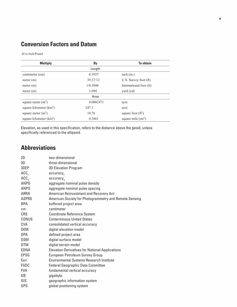
Conversion Factors and Datum SI to Inch/Pound
Multiply By To obtain
Length
centimeter (cm) 0.3937 inch (in.)meter (m) 39.37/12 U.S. Survey foot (ft) meter (m) 1/0.3048 International foot (ft)meter (m) 1.094 yard (yd)
Area
square meter (m2) 0.0002471 acre square kilometer (km2) 247.1 acresquare meter (m2) 10.76 square foot (ft2) square kilometer (km2) 0.3861 square mile (mi2)
Elevation, as used in this specification, refers to the distance above the geoid, unless specifically referenced to the ellipsoid.
Abbreviations2D two-dimensional3D three-dimensional3DEP 3D Elevation ProgramACCr accuracyrACCz accuracyzANPD aggregate nominal pulse densityANPS aggregate nominal pulse spacingARRA American Reinvestment and Recovery ActASPRS American Society for Photogrammetry and Remote SensingBPA buffered project areacm centimeterCRS Coordinate Reference SystemCONUS Conterminous United StatesCVA consolidated vertical accuracyDEM digital elevation modelDPA defined project areaDSM digital surface modelDTM digital terrain modelEDNA Elevation Derivatives for National ApplicationsEPSG European Petroleum Survey GroupEsri Environmental Systems Research InstituteFGDC Federal Geographic Data CommitteeFVA fundamental vertical accuracyGB gigabyteGIS geographic information systemGPS global positioning system
vi
ID identificationIMU inertial measurement unitkm kilometerkm2 square kilometerLAS LAS file format (.las)lidar light detection and rangingm metersmp Metadata Parserm2 square metersn/a not availableNAD 83 North American Datum of 1983NAVD 88 North American Vertical Datum of 1988NDEP National Digital Elevation ProgramNED National Elevation DatasetNEEA National Enhanced Elevation AssessmentNGP National Geospatial ProgramNGS National Geodetic SurveyNIR near infra redNPD nominal pulse densityNPS nominal pulse spacingNSSDA National Standards for Spatial Data AccuracyNVA nonvegetated vertical accuracyOGC Open Geospatial Consortiumpls/m2 pulses per square meterQA/QC quality assurance/quality controlQL quality levelRMSD root mean square differenceRMSDz root mean square difference in the z direction (elevation)RMSE root mean square errorRMSEr horizontal linear RMSE in the radial direction that includes both x and y errorsRMSEx horizontal linear RMSE in the x direction (Easting)RMSEy horizontal linear RMSE in the y direction (Northing)RMSEz vertical linear RMSE in the z direction (Elevation)SPCS State Plane Coordinate SystemSVA supplemental vertical accuracyTIN triangulated irregular networkUSGS U.S. Geological SurveyUTM Universal Transverse MercatorVVA Vegetated Vertical AccuracyWKT Well Known TextXML eXtensible Markup Language
Lidar Base Specification
By Hans Karl Heidemann
AbstractIn late 2009, a $14.3 million allocation from the
“American Recovery and Reinvestment Act” for new light detection and ranging (lidar) elevation data prompted the U.S. Geological Survey (USGS) National Geospatial Program (NGP) to develop a common base specification for all lidar data acquired for The National Map. Released as a draft in 2010 and formally published in 2012, the USGS–NGP “Lidar Base Specification Version 1.0” (now Lidar Base Specification) was quickly embraced as the foundation for numerous state, county, and foreign country lidar specifications.
Prompted by a growing appreciation for the wide applicability and inherent value of lidar, a USGS-led consortium of Federal agencies commissioned a National Enhanced Elevation Assessment (NEEA) study in 2010 to quantify the costs and benefits of a national lidar program. A 2012 NEEA report documented a substantial return on such an investment, defined five Quality Levels (QL) for elevation data, and recommended an 8-year collection cycle of Quality Level 2 (QL2) lidar data as the optimum balance of benefit and affordability. In response to the study, the USGS–NGP established the 3D Elevation Program (3DEP) in 2013 as the interagency vehicle through which the NEEA recommendations could be realized.
Lidar is a fast evolving technology, and much has changed in the industry since the final draft of the “Lidar Base Specification Version 1.0” was written. Lidar data have improved in accuracy and spatial resolution, geospatial accuracy standards have been revised by the American Society for Photogrammetry and Remote Sensing (ASPRS), industry standard file formats have been expanded, additional applications for lidar have become accepted, and the need for interoperable data across collections has been realized. This revision to the “Lidar Base Specification Version 1.0” publication addresses those changes and provides continued guidance towards a nationally consistent lidar dataset.
IntroductionAs the designated Office of Management and Budget
Circular A–16 lead agency for topographic elevation data, the U.S. Geological Survey (USGS), through the National
Geospatial Program (NGP, hereafter, USGS–NGP), has developed and adopted this specification as the base specification for the National interagency 3D Elevation Program (3DEP). This specification, developed with input from a broad coalition of Federal, state, and industry light detection and ranging (lidar) interests, also may serve, in whole or in part, as the foundation for many other lidar specifications. Overall movement throughout the industry toward more consistent practices in the collection, handling, processing, documentation, and delivery of lidar point cloud data will allow the technology and data to become more useful to a broader user base, and thereby benefit the Nation as a whole.
Although lidar data have been used in research and commercial mapping applications for more than a decade, lidar is still a relatively new technology (Stoker, 2013). Advancements and improvements in instrumentation, software, processes, applications, and understanding are constantly refined or developed. It would not be possible to develop a set of guidelines and specifications that addresses and keeps pace with all of these advances. This specification is based on the experience and research of the USGS–NGP pertaining to the lidar technology being used in the industry. Furthermore, the USGS–NGP acknowledges that a common set of best practices has not been developed or adopted by the industry for numerous processes and technical assessments (for example, measurement of density and distribution, classification accuracy, and calibration quality). The USGS encourages the development of such best practices with industry partners, other government agencies, and the appropriate professional organizations.
Unlike most other lidar data procurement specifications, which largely focus on the products derived from lidar point cloud data such as the bare-earth digital elevation model (DEM), this specification places particular emphasis on the handling of the source lidar point cloud data. These specifications are intended to ensure that the complete source dataset remains intact and viable to support the wide variety of DEM and non-DEM science and mapping applications that can benefit from lidar technology. The source dataset includes the data, metadata, descriptive documentation, quality information, and ancillary data—collected in accordance with the minimum parameters described within this specification.
2 Lidar Base Specification
Adherence to the specifications of the National Enhanced Elevation Assessment (NEEA) Quality Level 2 (QL2) and Quality Level 1 (QL1) lidar data ensures that point cloud and derivative products are suitable for the 3DEP and the National Elevation Dataset (NED) (Gesch, 2007). Data meeting Quality Level 3 (QL3) requirements will be suitable for incorporation into the NED. The 3DEP’s goal to fully realize the benefits documented in the NEEA report depends on the ability to manage, analyze, and exploit a lidar dataset spanning the Nation; the vast quantity of lidar data requires these functions be handled through computerized, machine-driven processes that will require uniformly formatted and organized data. Presidential Executive Order 13642, “Making Open and Machine Readable the New Default for Government Information,” requires agencies to implement an Open Data Policy, which makes government data easily accessible and usable (Obama, 2013). Adherence to these specifications ensures that the point cloud source data are handled in a uniform manner by all data providers and are consistently delivered to the USGS in clearly defined formats.
Purpose and Scope
The USGS intends to use this specification to acquire and procure lidar data and to create consistency across all USGS–NGP and partner-funded lidar collections, in particular those that support the NED and the 3DEP.
This base specification covers three different data QLs, defining minimum parameters for acceptance of the acquired lidar data for each QL. Local conditions in any given project, specialized applications for the data, or the preferences of cooperators, may mandate more stringent requirements. In these circumstances, the USGS may support or require the collection of more detailed, accurate, or value-added data. A list of common upgrades to the minimum requirements defined in this specification is provided in appendix 1, “Common Data Upgrades.”
A summary of the changes between the previous version of this specification (Version 1.0) and this revision (Version 1.1) is provided in the section “Changes in Version 1.1.”
Applicability
These specifications and guidelines are applicable to lidar data and deliverables supported in whole or in part with financial or in-kind contributions by or for the USGS–NGP or the 3DEP.
Maintenance Authority
The USGS–NGP is the maintenance authority for this specification.
Requirement Terminology
Individual requirements are captured throughout this specification as “shall” or “will” statements.
• A “shall” statement means that the requirement must be met in all cases.
• A “will” statement indicates that the requirement is expected to be met wherever possible, but exceptions to implementation may exist.
Background
The USGS–NGP has cooperated in the collection of many lidar datasets across the Nation for a wide array of applications. These collections have used a variety of specifications and have had a diverse set of product deliverables; however, the end result was incompatible datasets making cross-project analysis extremely difficult. The need for a single base specification was apparent, one that defined minimum collection parameters and a consistent set of deliverables
Because of the “American Reinvestment and Recovery Act” (ARRA) funding for The National Map (that began in late 2009), the rate of lidar data collection increased. This increase made it imperative that a single data specification be implemented to ensure consistency and improve data utility. Although the development of this specification was prompted by funding through the ARRA, the specification is intended to remain durable beyond ARRA-funded USGS–NGP projects.
The need for a single data specification has been reinforced by the inception of the 3DEP after the completion of the NEEA. The 3DEP is a cooperatively funded national elevation program led by the USGS. This program has been designed to meet the mission-critical data needs of the 3DEP partners and other users. A target state would produce full national QL2 (at least at this level) coverage in 8 years with lidar data in 49 States and Alaska being mapped at QL5 using other technologies. Products derived from 3DEP data would be available for the high-priority needs of partners and other users, who also would be able to use the original data to create their own products and services.
In addition, the USGS–NGP also uses lidar technology for specialized scientific research and other projects whose requirements are incompatible with the provisions of this specification. In such cases, and with properly documented justification supporting the need for the variance, waivers of any part or all of this specification may be granted by the USGS–NGP. In some cases, based on specific topography, land cover, intended application, or other factors, the USGS–NGP may require standards more rigorous than those defined in this specification. For any given collection, technical alternatives that enhance the data or associated products are encouraged and may be submitted with any proposal and will be given due professional consideration by the USGS–NGP.
Introduction 3
Changes in Version 1.1
1. For clarification, numerous sections of the specification have been editorially revised, and there has been minor reorganization of the document.
2. Glossary definitions have been updated to align with those in the new American Society for Photogrammetry and Remote Sensing (ASPRS) Positional Accuracy Standards for Digital Geospatial Data (American Society for Photogrammetry and Remote Sensing, 2014) and other industry publications, and several new definitions have been added. Notable among these are:• Aggregate nominal pulse density (and spacing),• Bridge and culvert,• Vegetated (and nonvegetated) vertical accuracy, and• Percentile.
3. Coincident with this revision of the specification, ASPRS also developed its own Positional Accuracy Standards for Digital Geospatial Data (American Society for Photogrammetry and Remote Sensing, 2014). With regard to elevation data, the new standards redefine how elevation accuracy is described and reported, and although any accuracy could be its own accuracy “class,” a number of common classes are explicitly defined. The previous ASPRS vertical accuracy standard (American Society for Photogrammetry and Remote Sensing, 1990) was based on contour interval (usually expressed in feet [ft]), resulting in non-integer accuracy thresholds when converted to the metric units typically used with lidar (for example, 9.25 centimeters [cm]). The new ASPRS standard abandons the dependency on contour interval and is based entirely in metric units; its common classes are integer (for example, 10.0 cm). The NEEA QL definitions used common accuracy classes based on the earlier accuracy definitions and, to eliminate confusion about accuracy requirements as 3DEP moves forward, the QL accuracy definitions were adjusted to match the new ASPRS classes. Another quality level, QL0, was added as a placeholder for the higher quality data anticipated with future advances in lidar technology. The requirements stated for QL0 are somewhat arbitrary and are subject to change in future revisions of this specification. The changes relevant to lidar data QLs in this revision of the specification are as follows:• QL0 was added with accuracy of 5.0 cm root mean
square error in z (RMSEz) and density of 8 pulses per square meter (pls/m2). This accuracy aligns with the ASPRS 5-cm vertical accuracy class.
• QL1 accuracy was changed from 9.25 cm RMSEz to 10.0 cm RMSEz. This accuracy does not correspond directly to any ASPRS accuracy class; it is a hybrid of QL2 accuracy and QL0 pulse density.
• QL2 accuracy was changed from 9.25 cm RMSEz to 10.0 cm RMSEz. This accuracy aligns with the ASPRS 10-cm vertical accuracy class.
• QL3 accuracy was changed from 18.5 cm RMSEz to 20.0 cm RMSEz and density was changed from 0.7 pls/m2 to 0.5 pls/m2. This accuracy aligns with the ASPRS 20-cm vertical accuracy class.
4. Also to align with the new ASPRS accuracy standards, accuracy is reported based on nonvegetated vertical accuracy (NVA) and vegetated vertical accuracy (VVA). These two classes replace the previously used fundamental, supplemental, and consolidated vertical accuracy (FVA, SVA, and CVA) classes.
5. The new ASPRS standards include recommendations tying the quantity of vertical accuracy check points required for a project to the areal extent of the project. Adherence to these recommendations is required by this specification.
6. QL2 has been established as the minimum required QL for new USGS–NGP lidar data collections.
7. Relative accuracy requirements for lidar data, within swath (intraswath) and between overlapping swaths (interswath) have been refined and established for each QL. A more detailed methodology for assessing and reporting these metrics is provided.
8. Lidar point data delivery is required in LAS v1.4 (American Society for Photogrammetry and Remote Sensing, 2011), Point Data Record Format 6, 7, 8, 9, or 10. Proper use of the Overlap and Withheld bit flags is required.
9. The block of lidar-specific metadata tags recommended in the previous version of this specification has been modified to reflect the other updates to the specification. The inclusion of this block is required in all lidar point data eXtensible Markup Language (XML) metadata files.
10. The 2 gigabyte (GB) limit on swath file size has been removed, although the method for splitting large swath files remains in the specification for use in situations where a data producer needs to produce smaller files.
11. The test area for assessing classification accuracy was changed from 1 kilometer square to 1 square kilometer.
12. Two additional point classification types are required:• Class 17, Bridges, and• Class 18, High Noise.
13. Anticipating that projects will more frequently use multiple coverage collection (for example, overlap greater than 50 percent) to achieve the higher required pulse density, terminology and requirements for this data organization have been added.
4 Lidar Base Specification
14. Requirements for datum and coordinate reference systems have been refined and clarified.
15. Development and delivery of breaklines is required for all hydro-flattened water bodies, regardless of the methodology used by the data producer for hydro-flattening.
16. Requirements and guidelines for flightline overlap and scan angle limits have been removed. Data producers are cautioned to be more rigorous about gaps in and the relative accuracy of the point cloud data.
Changes in Version 1.2
1. For clarification, the publication was modified to omit versioning from the main title. No changes were made to the content of the specification.
Collection
Collection Area
The defined project area (DPA) shall be buffered by a minimum of 100 meters (m) to create a buffered project area (BPA). Data collection is required for the full extent of the BPA.
In order for all products to be consistent to the edge of the DPA, all products shall be generated to the full extent of the BPA. Because data and products are generated for the complete BPA, they shall also be delivered to the customer. Data and products in the buffer (the area between the DPA and the BPA) will not be tested for any quality requirement. Control points may be located in the buffer; check points shall not be located in the buffered area.
Quality Level
The minimum acceptable QL for USGS–NGP and 3DEP collections is QL2, as defined in this specification.
Multiple Discrete Returns
Deriving and delivering multiple discrete returns is required in all data collection efforts. Data collection shall be capable of at least three returns per pulse. Full waveform collection is acceptable and will be promoted; however, full waveform data are regarded as supplemental information.
Intensity Values
Intensity values are required for each multiple discrete return. The values recorded in the LAS files shall be
normalized to 16 bit, as described in the LAS Specification version 1.4 (American Society for Photogrammetry and Remote Sensing, 2011).
Nominal Pulse Spacing
The term nominal pulse spacing (NPS) has been in use across the industry since its beginnings; the counterpart term, nominal pulse density (NPD), came into use when collection densities began to fall below 1 pls/m2. These terms were used by instrument manufacturers and data producers to describe instrument performance and collection targets and, in these contexts, the terms almost always refer to single swath, first return only collection. For much of the history of lidar use, most collections were planned and executed as single-coverage flight missions: thus, these terms also were used by data consumers, whose interests are naturally focused on the net result of a collection. Thus, the terms NPS and NPD could be used by the entire community without misunderstanding.
The trend towards achieving the specified “NPS” for a project through multiple passes, overlap greater than 50 percent, multi-channel instruments, and multiple instruments on a single collection platform has expanded the industry’s options and flexibility in designing lidar collection missions. Complexity and confusion have also been added to assessment and reporting standards. The net pulse density of a collection may be several times greater than the planned density of a single swath. The terms “NPS” and “NPD” can have quite different meanings to different members of the lidar community.
In this specification, the terms NPS and NPD will continue to reference single instrument, single swath, first return only lidar point data. Maintaining this terminology provides a consistent and understandable metric for communication regarding data collection.
Multiple channels of data from a single instrument are regarded as a single swath. In this sense, a single instrument is regarded as one in which both channels meet the following criteria:
• They share fundamental hardware components of the system, such as global positioning system (GPS), Inertial Measurement Unit (IMU), laser, mirror or prism, and detector assembly,
• They share a common calibration or boresighting procedure and solution, and
• They are designed and intended to operate as a single-sensor unit.
Assessment and reporting of the NPS is made against single swath, single instrument, first return only data, including only the geometrically usable part of the swath (typically the center 95 percent) and excluding acceptable data voids. The NPS can be predicted using flight planning software, or empirically calculated by delineating a 1 square
Collection 5
kilometer (km2) (or greater) polygon that is representative of the overall pulse density of the swath. The NPS is the square root of the average area per point (the area of the polygon divided by the number of points it contains). These two techniques will produce slightly different values. The NPS is largely regarded as a mission design and planning metric.
Higher net densities of lidar point measurements are being achieved more often by using multiple coverages, creating a need for a separate new term to prevent confusion with NPS and NPD. This specification will use the terms aggregate nominal pulse spacing (ANPS) and aggregate nominal pulse density (ANPD) to describe the net overall pulse spacing and density, respectively. On projects designed to achieve the ANPS through a single coverage, ANPS and NPS are equal.
Like NPS, ANPS includes only the geometrically usable part of the swaths (typically the center 95 percent), excludes acceptable data voids, and can be empirically calculated using the method described above for NPS. Conversion between ANPS and ANPD is the same as for NPS and NPD. ANPS is the metric of a lidar dataset for users.
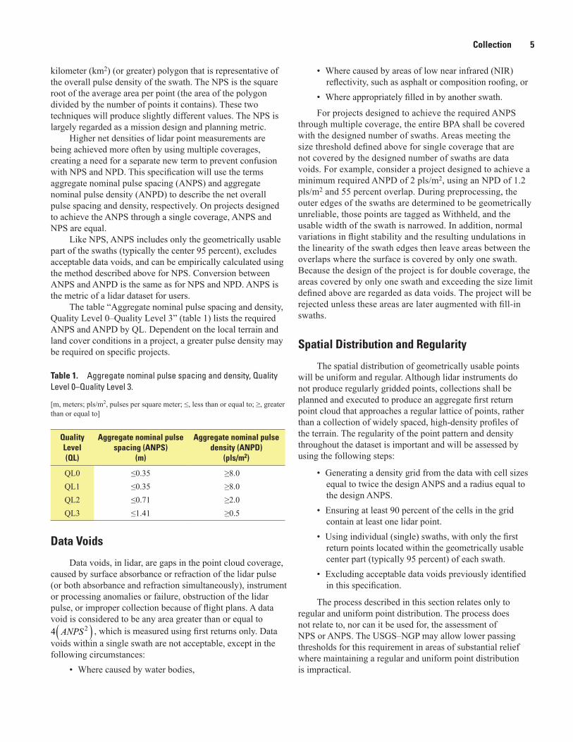
The table “Aggregate nominal pulse spacing and density, Quality Level 0–Quality Level 3” (table 1) lists the required ANPS and ANPD by QL. Dependent on the local terrain and land cover conditions in a project, a greater pulse density may be required on specific projects.
Table 1. Aggregate nominal pulse spacing and density, Quality Level 0–Quality Level 3.
[m, meters; pls/m2, pulses per square meter; ≤, less than or equal to; ≥, greater than or equal to]
Quality Level (QL)
Aggregate nominal pulse spacing (ANPS)
(m)
Aggregate nominal pulse density (ANPD)
(pls/m2)
QL0 ≤0.35 ≥8.0QL1 ≤0.35 ≥8.0QL2 ≤0.71 ≥2.0QL3 ≤1.41 ≥0.5
• Where caused by areas of low near infrared (NIR) reflectivity, such as asphalt or composition roofing, or
• Where appropriately filled in by another swath.
For projects designed to achieve the required ANPS through multiple coverage, the entire BPA shall be covered with the designed number of swaths. Areas meeting the size threshold defined above for single coverage that are not covered by the designed number of swaths are data voids. For example, consider a project designed to achieve a minimum required ANPD of 2 pls/m2, using an NPD of 1.2 pls/m2 and 55 percent overlap. During preprocessing, the outer edges of the swaths are determined to be geometrically unreliable, those points are tagged as Withheld, and the usable width of the swath is narrowed. In addition, normal variations in flight stability and the resulting undulations in the linearity of the swath edges then leave areas between the overlaps where the surface is covered by only one swath. Because the design of the project is for double coverage, the areas covered by only one swath and exceeding the size limit defined above are regarded as data voids. The project will be rejected unless these areas are later augmented with fill-in swaths.
Spatial Distribution and Regularity
The spatial distribution of geometrically usable points will be uniform and regular. Although lidar instruments do not produce regularly gridded points, collections shall be planned and executed to produce an aggregate first return point cloud that approaches a regular lattice of points, rather than a collection of widely spaced, high-density profiles of the terrain. The regularity of the point pattern and density throughout the dataset is important and will be assessed by using the following steps:
• Generating a density grid from the data with cell sizes equal to twice the design ANPS and a radius equal to the design ANPS.
• Ensuring at least 90 percent of the cells in the grid contain at least one lidar point.
• Using individual (single) swaths, with only the first return points located within the geometrically usable center part (typically 95 percent) of each swath.
• Excluding acceptable data voids previously identified in this specification.
The process described in this section relates only to regular and uniform point distribution. The process does not relate to, nor can it be used for, the assessment of NPS or ANPS. The USGS–NGP may allow lower passing thresholds for this requirement in areas of substantial relief where maintaining a regular and uniform point distribution is impractical.
Data Voids
Data voids, in lidar, are gaps in the point cloud coverage, caused by surface absorbance or refraction of the lidar pulse (or both absorbance and refraction simultaneously), instrument or processing anomalies or failure, obstruction of the lidar pulse, or improper collection because of flight plans. A data void is considered to be any area greater than or equal to( )2 4 ANPS , which is measured using first returns only. Data
voids within a single swath are not acceptable, except in the following circumstances:
• Where caused by water bodies,
6 Lidar Base Specification
Collection Conditions
Conditions for collection of lidar data will follow these guidelines:
• Atmospheric conditions shall be cloud and fog free between the aircraft and ground during all collection operations.
• Ground conditions shall be snow free. Very light, undrifted snow may be acceptable in special cases, with prior approval.
• Ground conditions shall be free of extensive flooding or any other type of inundation.
Although leaf-off vegetation conditions are preferred, many factors beyond human control may affect dormant conditions at the time of any collection, therefore, the USGS–NGP only requires that penetration to the ground be adequate to produce an accurate and reliable bare-earth surface for the prescribed QL. With prior approval from the USGS–NGP, collections for specific research projects may be exempt from this requirement.
Data Processing and Handling
The ASPRS LAS File Format
All processing will be carried out with the understanding that all point deliverables are required to be fully compliant with ASPRS LAS Specification, version 1.4, using Point Data Record Format 6, 7, 8, 9 or 10. Data producers are encouraged to review the LAS Specification version 1.4 in detail (American Society for Photogrammetry and Remote Sensing, 2011).
Full Waveform
If full waveform data are recorded during collection, the waveform packets shall be delivered. LAS Specification version 1.4 deliverables including waveform data shall use external auxiliary files with the extension .wdp to store waveform packet data. See the LAS Specification version 1.4 for additional information (American Society for Photogrammetry and Remote Sensing, 2011).
Time of Global Positioning System Data
The time of global positioning system (GPS) data shall be recorded as Adjusted GPS Time, at a precision sufficient to allow unique timestamps for each pulse. Adjusted GPS Time is defined to be Standard (or satellite) GPS time minus 109. The encoding tag in the LAS header shall be properly set. See the LAS Specification version 1.4 for additional information (American Society for Photogrammetry and Remote Sensing, 2011).
Datums
All data collected shall be tied to the datums listed below:1. For the Conterminous United States (CONUS),
unless otherwise specified by the user and agreed to in advance by the USGS–NGP:• The horizontal datum for latitude and longitude
and ellipsoid heights will be the North American Datum of 1983 (NAD 83) using the most recently published adjustment of the National Geodetic Survey (NGS) (currently NAD 83, epoch 2010.00).
• The vertical datum for orthometric heights will be the North American Vertical Datum of 1988 (NAVD 88).
• The geoid model used to convert between ellipsoid heights and orthometric heights will be the latest hybrid geoid model of NGS, supporting the latest realization of NAD 83 (currently GEOD12A model).
2. For Alaska, American Samoa, Commonwealth of the Northern Mariana Islands, Guam, Hawaii, Puerto Rico, U.S. Virgin Islands, and other areas:• Horizontal and vertical datums, ellipsoids, and
geoids shall be specified and agreed to by the USGS–NGP and all collection partners in advance of collection.
Coordinate Reference System
Lidar data for CONUS will be processed and delivered in the most accurate Coordinate Reference System (CRS) available for a project location, usually State Plane Coordinate System (SPCS) or a state system. Universal Transverse Mercator (UTM) also may be used, particularly when a single suitable local SPCS is not available, UTM is needed for compatibility with existing data for the area, or is needed for other reasons. Other CRSs may be used with prior approval from the USGS–NGP.
For Alaska, American Samoa, Commonwealth of the Northern Mariana Islands, Guam, Hawaii, Puerto Rico, U.S. Virgin Islands, and other areas, the horizontal and vertical CRS (specifically including the units) shall be specified and agreed to in advance of collection by the USGS–NGP and all collection partners.
Each project shall be processed and delivered in a single CRS, except in cases where a project area covers multiple CRSs such that processing in a single CRS would introduce unacceptable distortions in part of the project area. In such cases, the project area is to be split into subareas appropriate for each CRS. Each subarea shall be processed and delivered as a separate subproject with its own CRS. All requirements
Data Processing and Handling 7
for a single project will apply to each subproject, notably the inclusion of the required buffer area and delivery of DPA and BPA boundaries. These boundaries are required to ensure that the datasets can subsequently be merged without introducing duplicate points. The DPA boundaries of adjacent subareas shall have topologically coincident boundaries along their common borders.
In all cases, the CRS that is used shall be recognized and published by the European Petroleum Survey Group (EPSG) and correctly recognized by industry standard geographic information system (GIS) software applications.
Units of Reference
All references to the unit of measure “Feet” and “Foot” shall specify “International,” “Intl,” “U.S. Survey,” or “US.”
Swath Identification
At the time of its creation and prior to any further processing, each swath shall be assigned a unique File Source Identification (ID), and each point within the swath shall be assigned a Point Source ID equal to the File Source ID. The Point Source ID on each point will be persisted unchanged throughout all processing and delivery. See the LAS Specification version 1.4 (American Society for Photogrammetry and Remote Sensing, 2011).
Point Families
Point families (multiple return “children” of a single “parent” pulse) will be maintained throughout all processing before tiling. Multiple returns from a given pulse will be stored in sequential (collected) order.
Swath Size and Segmentation
The widespread adoption of 64-bit operating systems in mainstream computing (most notably Windows-7, 64-bit or newer operating systems) has obviated the earlier need for 2 GB limits on swath file sizes. Unless otherwise required by the data producer, lidar swaths may be of any file size supported within a 64-bit computing system. In cases where segmentation of the swaths is required by the data producer, the following requirements apply:
• Subswath segments of a given original swath will be of comparable size.
• Each subswath shall retain the File Source ID of the original complete swath.
• Points within each subswath shall retain the Point Source ID of the original complete swath.
• Each subswath file shall be named identically to the original complete swath, with the addition of an ordered alphabetic suffix to the name (“-a,” “-b,” …, “-n”). The order of the named subswaths shall be consistent with the collection order of the points (“-a” will be the first subswath; “-n” will be the last subswath).
• Point families will be maintained intact within each subswath.
• Subswaths will be broken at the edge of the scan line.
Scope of Collection
All collected swaths shall be delivered as part of the Raw Data Deliverable, including, calibration swaths and cross-ties. All collected returns within each swath shall also be delivered. No points are to be deleted from the swath LAS files. Exceptions to this rule are the extraneous data outside of the BPA (such as aircraft turns, transit between the collection area and airport, and transit between fill-in areas). These points may be permanently removed from swaths. Swaths that are being completely discarded by the vendor and reflown do not need to be delivered.
Positional Accuracy Validation
Before classification of and development of derivative products from the point cloud, the absolute and relative vertical accuracy of the point cloud shall be verified. A detailed report of the validation processes used shall be delivered.
Relative Vertical AccuracyRelative vertical accuracy refers to the internal geometric
quality of a lidar dataset, without regard to surveyed ground control. Two primary factors need to be considered in lidar data vertical accuracy:
• Smooth surface repeatability (intraswath), and• Overlap consistency (interswath).
In ideal theoretical conditions, smooth surface repeatability is a measure of variations documented on a surface that would be expected to be flat and without variation. Users of lidar technology commonly refer to these variations as “noise.” Single-swath data will be assessed using only single returns in nonvegetated areas. Repeatability will be evaluated by measuring departures from planarity of single returns from hard planar surfaces, normalizing for actual variation in the surface elevation. Repeatability of only single returns will then be assessed at multiple locations within hard surfaced areas (for example, parking lots or large rooftops).
8 Lidar Base Specification
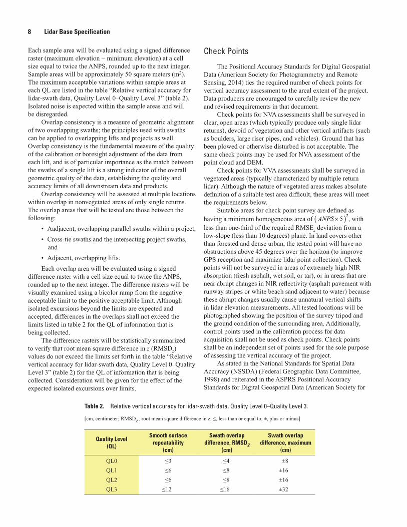
Each sample area will be evaluated using a signed difference raster (maximum elevation − minimum elevation) at a cell size equal to twice the ANPS, rounded up to the next integer. Sample areas will be approximately 50 square meters (m2). The maximum acceptable variations within sample areas at each QL are listed in the table “Relative vertical accuracy for lidar-swath data, Quality Level 0–Quality Level 3” (table 2). Isolated noise is expected within the sample areas and will be disregarded.
Overlap consistency is a measure of geometric alignment of two overlapping swaths; the principles used with swaths can be applied to overlapping lifts and projects as well. Overlap consistency is the fundamental measure of the quality of the calibration or boresight adjustment of the data from each lift, and is of particular importance as the match between the swaths of a single lift is a strong indicator of the overall geometric quality of the data, establishing the quality and accuracy limits of all downstream data and products.
Overlap consistency will be assessed at multiple locations within overlap in nonvegetated areas of only single returns. The overlap areas that will be tested are those between the following:
• Aadjacent, overlapping parallel swaths within a project,• Cross-tie swaths and the intersecting project swaths,
and• Adjacent, overlapping lifts.Each overlap area will be evaluated using a signed
difference raster with a cell size equal to twice the ANPS, rounded up to the next integer. The difference rasters will be visually examined using a bicolor ramp from the negative acceptable limit to the positive acceptable limit. Although isolated excursions beyond the limits are expected and accepted, differences in the overlaps shall not exceed the limits listed in table 2 for the QL of information that is being collected.
The difference rasters will be statistically summarized to verify that root mean square difference in z (RMSDz) values do not exceed the limits set forth in the table “Relative vertical accuracy for lidar-swath data, Quality Level 0–Quality Level 3” (table 2) for the QL of information that is being collected. Consideration will be given for the effect of the expected isolated excursions over limits.
Check Points
The Positional Accuracy Standards for Digital Geospatial Data (American Society for Photogrammetry and Remote Sensing, 2014) ties the required number of check points for vertical accuracy assessment to the areal extent of the project. Data producers are encouraged to carefully review the new and revised requirements in that document.
Check points for NVA assessments shall be surveyed in clear, open areas (which typically produce only single lidar returns), devoid of vegetation and other vertical artifacts (such as boulders, large riser pipes, and vehicles). Ground that has been plowed or otherwise disturbed is not acceptable. The same check points may be used for NVA assessment of the point cloud and DEM.
Check points for VVA assessments shall be surveyed in vegetated areas (typically characterized by multiple return lidar). Although the nature of vegetated areas makes absolute definition of a suitable test area difficult, these areas will meet the requirements below.
Suitable areas for check point survey are defined ashaving a minimum homogeneous area of ( )2 5 ANPS × , withless than one-third of the required RMSEz deviation from a low-slope (less than 10 degrees) plane. In land covers other than forested and dense urban, the tested point will have no obstructions above 45 degrees over the horizon (to improve GPS reception and maximize lidar point collection). Check points will not be surveyed in areas of extremely high NIR absorption (fresh asphalt, wet soil, or tar), or in areas that are near abrupt changes in NIR reflectivity (asphalt pavement with runway stripes or white beach sand adjacent to water) because these abrupt changes usually cause unnatural vertical shifts in lidar elevation measurements. All tested locations will be photographed showing the position of the survey tripod and the ground condition of the surrounding area. Additionally, control points used in the calibration process for data acquisition shall not be used as check points. Check points shall be an independent set of points used for the sole purpose of assessing the vertical accuracy of the project.
As stated in the National Standards for Spatial Data Accuracy (NSSDA) (Federal Geographic Data Committee, 1998) and reiterated in the ASPRS Positional Accuracy Standards for Digital Geospatial Data (American Society for
Table 2. Relative vertical accuracy for lidar-swath data, Quality Level 0–Quality Level 3.
[cm, centimeter; RMSDZ , root mean square difference in z; ≤, less than or equal to; ±, plus or minus]
Quality Level (QL)
Smooth surface repeatability
(cm)
Swath overlapdifference, RMSDZ
(cm)
Swath overlap difference, maximum
(cm)
QL0 ≤3 ≤4 ±8QL1 ≤6 ≤8 ±16QL2 ≤6 ≤8 ±16QL3 ≤12 ≤16 ±32
Data Processing and Handling 9
Photogrammetry and Remote Sensing, 2014), it is unrealistic to prescribe detailed requirements for check point locations, as many unpredictable factors will affect field operations and decisions, and the data producer must often have the freedom to use their best professional judgment. The quantity and location of check points shall meet the following requirements, unless alternative criteria are approved by the USGS–NGP in advance:1. The ASPRS-recommended total number of check points
for a given project size shall be met.
2. The ASPRS-recommended distribution of the total number of check points between NVA and VVA assessments shall be met.
3. Check points within each assessment type (NVA and VVA) will be well-distributed across the entire project area. See the glossary at the end of this specification for a definition of “well-distributed.”
4. Within each assessment type, check points will be distributed among all constituent land cover types in approximate proportion to the areas of those land cover types (American Society for Photogrammetry and Remote Sensing, 2014).
Absolute Vertical AccuracyAbsolute vertical accuracy of the lidar data and the
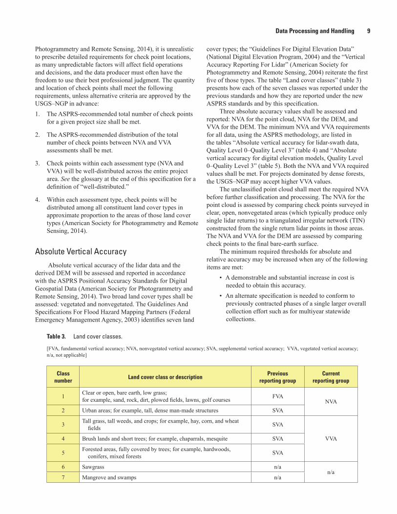
derived DEM will be assessed and reported in accordance with the ASPRS Positional Accuracy Standards for Digital Geospatial Data (American Society for Photogrammetry and Remote Sensing, 2014). Two broad land cover types shall be assessed: vegetated and nonvegetated. The Guidelines And Specifications For Flood Hazard Mapping Partners (Federal Emergency Management Agency, 2003) identifies seven land
cover types; the “Guidelines For Digital Elevation Data” (National Digital Elevation Program, 2004) and the “Vertical Accuracy Reporting For Lidar” (American Society for Photogrammetry and Remote Sensing, 2004) reiterate the first five of those types. The table “Land cover classes” (table 3) presents how each of the seven classes was reported under the previous standards and how they are reported under the new ASPRS standards and by this specification.
Three absolute accuracy values shall be assessed and reported: NVA for the point cloud, NVA for the DEM, and VVA for the DEM. The minimum NVA and VVA requirements for all data, using the ASPRS methodology, are listed in the tables “Absolute vertical accuracy for lidar-swath data, Quality Level 0–Quality Level 3” (table 4) and “Absolute vertical accuracy for digital elevation models, Quality Level 0–Quality Level 3” (table 5). Both the NVA and VVA required values shall be met. For projects dominated by dense forests, the USGS–NGP may accept higher VVA values.
The unclassified point cloud shall meet the required NVA before further classification and processing. The NVA for the point cloud is assessed by comparing check points surveyed in clear, open, nonvegetated areas (which typically produce only single lidar returns) to a triangulated irregular network (TIN) constructed from the single return lidar points in those areas. The NVA and VVA for the DEM are assessed by comparing check points to the final bare-earth surface.
The minimum required thresholds for absolute and relative accuracy may be increased when any of the following items are met:
• A demonstrable and substantial increase in cost is needed to obtain this accuracy.
• An alternate specification is needed to conform to previously contracted phases of a single larger overall collection effort such as for multiyear statewide collections.
Table 3. Land cover classes.
[FVA, fundamental vertical accuracy; NVA, nonvegetated vertical accuracy; SVA, supplemental vertical accuracy; VVA, vegetated vertical accuracy; n/a, not applicable]
Class number
Land cover class or descriptionPrevious
reporting groupCurrent
reporting group
1 Clear or open, bare earth, low grass;for example, sand, rock, dirt, plowed fields, lawns, golf courses FVA
NVA2 Urban areas; for example, tall, dense man-made structures SVA
3 Tall grass, tall weeds, and crops; for example, hay, corn, and wheat fields SVA
VVA4 Brush lands and short trees; for example, chaparrals, mesquite SVA
5 Forested areas, fully covered by trees; for example, hardwoods, conifers, mixed forests SVA
6 Sawgrass n/an/a
7 Mangrove and swamps n/a
10 Lidar Base Specification
• The USGS–NGP agrees that the use of an alternate specification is reasonable and in the best interest of all stakeholders.
Use of the LAS Withheld Flag
Outliers, blunders, noise points, geometrically unreliable points near the extreme edge of the swath, and other points the data producer deems unusable are to be identified using the Withheld Flag, as defined in the LAS Specification version 1.4 (American Society for Photogrammetry and Remote Sensing, 2011).
The Withheld Flag is primarily used to denote points identified during preprocessing or through automated post-processing routines as geometrically unusable.
Noise points subsequently identified during manual classification and quality assurance/quality control (QA/QC) are typically assigned the appropriate standard LAS classification values for noise–Class 7 is used for Low Noise and Class 18 is used for High Noise.
Use of the LAS Overlap Flag
The LAS Specification version 1.4 (American Society for Photogrammetry and Remote Sensing, 2011) includes a new overlap flag. Although strictly speaking, the term “overlap” means all lidar points lying within any overlapping areas of two or more swaths, the flag is intended to identify overage points, which are only a subset of overlap points. See the glossary for more information on the difference between overlap and overage. Having overage points identified allows for their easy exclusion from subsequent processes where the increased density and elevation variability they introduce is unwanted (for example, DEM generation).
Overage points have commonly been identified using Class 12, precluding other valuable classification (for example, bare earth, water). The overlap flag provides a discrete method to identify overage points while preserving the ability to classify the points in the normal way.
Overage points shall be identified using the LAS overlap flag in all point cloud deliverables.
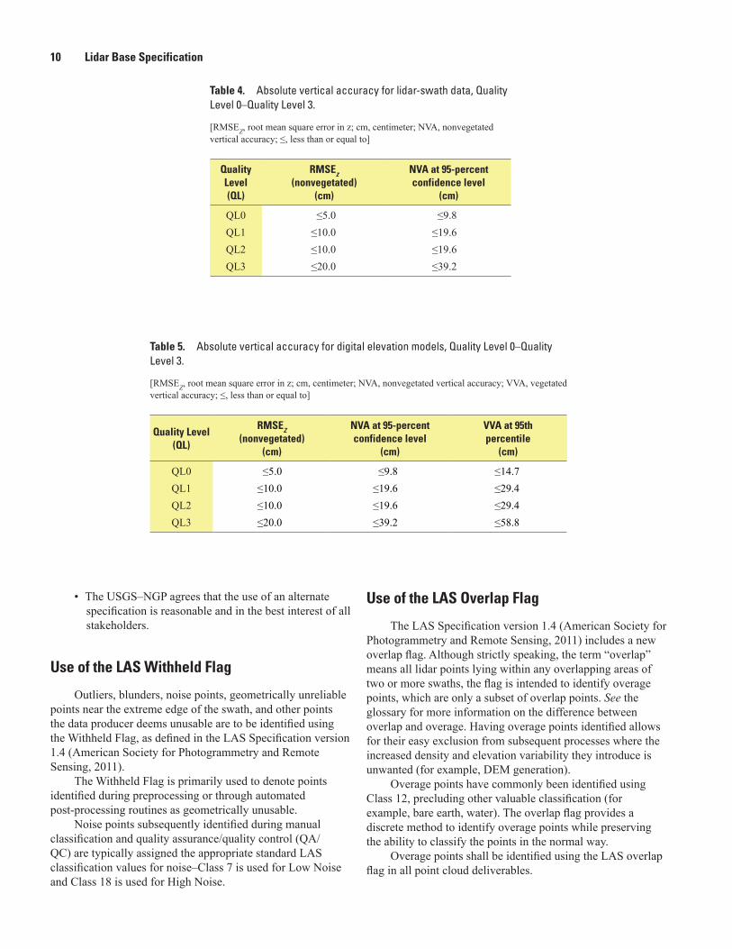
Table 4. Absolute vertical accuracy for lidar-swath data, Quality Level 0–Quality Level 3.
[RMSEZ, root mean square error in z; cm, centimeter; NVA, nonvegetated vertical accuracy; ≤, less than or equal to]
Quality Level (QL)
RMSEz (nonvegetated)
(cm)
NVA at 95-percentconfidence level
(cm)
QL0 ≤5.0 ≤9.8QL1 ≤10.0 ≤19.6QL2 ≤10.0 ≤19.6QL3 ≤20.0 ≤39.2
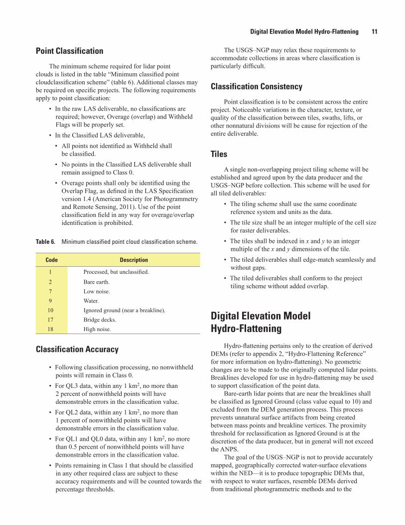
Table 5. Absolute vertical accuracy for digital elevation models, Quality Level 0–Quality Level 3.
[RMSEZ, root mean square error in z; cm, centimeter; NVA, nonvegetated vertical accuracy; VVA, vegetated vertical accuracy; ≤, less than or equal to]
Quality Level (QL)
RMSEZ (nonvegetated)
(cm)
NVA at 95-percentconfidence level
(cm)
VVA at 95thpercentile
(cm)
QL0 ≤5.0 ≤9.8 ≤14.7QL1 ≤10.0 ≤19.6 ≤29.4QL2 ≤10.0 ≤19.6 ≤29.4QL3 ≤20.0 ≤39.2 ≤58.8
Digital Elevation Model Hydro-Flattening 11
Point Classification
The minimum scheme required for lidar point clouds is listed in the table “Minimum classified point cloudclassification scheme” (table 6). Additional classes may be required on specific projects. The following requirements apply to point classification:
• In the raw LAS deliverable, no classifications are required; however, Overage (overlap) and Withheld Flags will be properly set.
• In the Classified LAS deliverable,• All points not identified as Withheld shall
be classified.• No points in the Classified LAS deliverable shall
remain assigned to Class 0.• Overage points shall only be identified using the
Overlap Flag, as defined in the LAS Specification version 1.4 (American Society for Photogrammetry and Remote Sensing, 2011). Use of the point classification field in any way for overage/overlap identification is prohibited.
Classification Accuracy
• Following classification processing, no nonwithheld points will remain in Class 0.
• For QL3 data, within any 1 km2, no more than 2 percent of nonwithheld points will have demonstrable errors in the classification value.
• For QL2 data, within any 1 km2, no more than 1 percent of nonwithheld points will have demonstrable errors in the classification value.
• For QL1 and QL0 data, within any 1 km2, no more than 0.5 percent of nonwithheld points will have demonstrable errors in the classification value.
• Points remaining in Class 1 that should be classified in any other required class are subject to these accuracy requirements and will be counted towards the percentage thresholds.
The USGS–NGP may relax these requirements to accommodate collections in areas where classification is particularly difficult.
Classification Consistency
Point classification is to be consistent across the entire project. Noticeable variations in the character, texture, or quality of the classification between tiles, swaths, lifts, or other nonnatural divisions will be cause for rejection of the entire deliverable.
Tiles
A single non-overlapping project tiling scheme will be established and agreed upon by the data producer and the USGS–NGP before collection. This scheme will be used for all tiled deliverables:
• The tiling scheme shall use the same coordinate reference system and units as the data.
• The tile size shall be an integer multiple of the cell size for raster deliverables.
• The tiles shall be indexed in x and y to an integer multiple of the x and y dimensions of the tile.
• The tiled deliverables shall edge-match seamlessly and without gaps.
• The tiled deliverables shall conform to the project tiling scheme without added overlap.
Digital Elevation Model Hydro-Flattening
Hydro-flattening pertains only to the creation of derived DEMs (refer to appendix 2, “Hydro-Flattening Reference” for more information on hydro-flattening). No geometric changes are to be made to the originally computed lidar points. Breaklines developed for use in hydro-flattening may be used to support classification of the point data.
Bare-earth lidar points that are near the breaklines shall be classified as Ignored Ground (class value equal to 10) and excluded from the DEM generation process. This process prevents unnatural surface artifacts from being created between mass points and breakline vertices. The proximity threshold for reclassification as Ignored Ground is at the discretion of the data producer, but in general will not exceed the ANPS.
The goal of the USGS–NGP is not to provide accurately mapped, geographically corrected water-surface elevations within the NED—it is to produce topographic DEMs that, with respect to water surfaces, resemble DEMs derived from traditional photogrammetric methods and to the
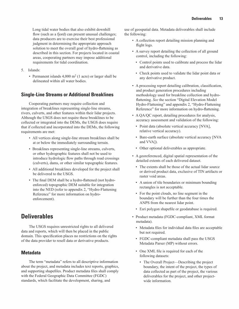
Table 6. Minimum classified point cloud classification scheme.
Code Description
1 Processed, but unclassified.
2 Bare earth.7 Low noise.9 Water.10 Ignored ground (near a breakline).17 Bridge decks.18 High noise.

12 Lidar Base Specification
degree practical are free of unnatural triangulation effects. Best professional judgment should be used to achieve this traditional smooth water-surface effect.
The requirements for hydro-flattening are listed below. These requirements also define the minimum features for which breaklines shall be collected and delivered. 1. Inland ponds and lakes:
• Water bodies of 8,000 m2 (2 acres) or greater surface area at the time of collection shall be flattened.
• Flattened water bodies shall present a flat and level water surface (a single elevation for every bank vertex defining the water body’s perimeter).
• The entire water-surface edge shall be at or below the immediately surrounding terrain (the presence of floating water bodies will be cause for rejection of the deliverable).
• Long impoundments—such as reservoirs, inlets, and fjords, whose water-surface elevations decrease with downstream travel—shall be treated as streams or rivers.
2. Inland streams and rivers:• Streams and rivers of a 30-m (100-ft) nominal width
shall be flattened.• Streams or rivers whose width varies above and below
30 meters will not be broken into multiple segments; data producers will use their best professional cartographic judgment in determining when a stream or river has attained a nominal 30-m width.
• Flattened streams and rivers shall present a flat and level water surface bank-to-bank (perpendicular to the apparent flow centerline).
• Flattened streams and rivers shall present a gradient downhill water surface, following the immediately surrounding terrain.
• In cases of sharp turns of rapidly moving water, where the natural water surface is notably not level bank-to-bank, the water surface will be represented as it exists while maintaining an aesthetic cartographic appearance.
• The entire water-surface edge shall be at or below the immediately surrounding terrain.
• Stream channels shall break at culvert locations leaving the roadway over the culvert intact.
• Bridges in all their forms shall be removed from the DEM.
• Streams shall be continuous at bridge locations.• When the identification of a structure as a bridge or
culvert cannot be made definitively, the feature shall be regarded as a culvert.
3. Non-tidal boundary waters:• Boundary waters, regardless of size, shall be
represented only as an edge or edges within the project; collection does not include the opposite shore.
• The entire water-surface edge shall be at or below the immediately surrounding terrain.
• The water-surface elevation will be consistent throughout the project.
• The water surface shall be flat and level, as appropriate for the type of water body (level for lakes, a gradient for streams and rivers).
• Any unusual changes in the water-surface elevation during the course of the collection (such as increased upstream dam discharge) shall be documented in the project metadata.
• In the event of an unusual change in water-surface elevation, the water body shall be handled as described in “4. Tidal Waters” (below).
4. Tidal waters: Tidal water bodies are defined as any water body
that is affected by tidal variations, including oceans, seas, gulfs, bays, inlets, salt marshes, and large lakes. Tidal variations during data collection or between different data collections will result in lateral and vertical discontinuities along shorelines. As it is the USGS–NGP’s intent for the DEM to represent as much ground as the collected data permits, lidar ground points shall not be removed for the sake of adjusting a shoreline inland to match another shoreline. Likewise, adjusting a shoreline outland will create an equally unacceptable area of unmeasured land in the DEM. It is recommended that, to the highest degree practical, collections be planned to minimize tidal differences at the land-water interface. In addition to meeting the requirements for inland water bodies listed in “1. Inland ponds and lakes” and “2. Inland streams and rivers,” above, as appropriate, the treatment of tidal water bodies shall also meet the following requirements:• Within each water body, the water surface shall
be flat and level for each different water-surface elevation.
• Vertical discontinuities within a water body resulting from tidal variations during the collection are considered normal and shall be retained in the final DEM.
• Horizontal discontinuities along the shoreline of a water body resulting from tidal variations during the collection are considered normal and shall be retained in the final DEM.
Deliverables 13
Long tidal water bodies that also exhibit downhill flow (such as a fjord) can present unusual challenges; data producers are to exercise their best professional judgment in determining the appropriate approach solution to meet the overall goal of hydro-flattening as described in this section. For projects located in coastal areas, cooperating partners may impose additional requirements for tidal coordination.
5. Islands:• Permanent islands 4,000 m2 (1 acre) or larger shall be
delineated within all water bodies.
Single-Line Streams or Additional Breaklines
Cooperating partners may require collection and integration of breaklines representing single-line streams, rivers, culverts, and other features within their lidar projects. Although the USGS does not require these breaklines to be collected or integrated into the DEMs, the USGS does require that if collected and incorporated into the DEMs, the following requirements are met:
• All vertices along single-line stream breaklines shall be at or below the immediately surrounding terrain.
• Breaklines representing single-line streams, culverts, or other hydrographic features shall not be used to introduce hydrologic flow paths through road crossings (culverts), dams, or other similar topographic features.
• All additional breaklines developed for the project shall be delivered to the USGS.
• The final DEM shall be a hydro-flattened (not hydro-enforced) topographic DEM suitable for integration into the NED (refer to appendix 2, “Hydro-Flattening Reference” for more information on hydro-enforcement).
DeliverablesThe USGS requires unrestricted rights to all delivered
data and reports, which will then be placed in the public domain. This specification places no restrictions on the rights of the data provider to resell data or derivative products.
Metadata
The term “metadata” refers to all descriptive information about the project, and metadata includes text reports, graphics, and supporting shapefiles. Product metadata files shall comply with the Federal Geographic Data Committee (FGDC) standards, which facilitate the development, sharing, and
use of geospatial data. Metadata deliverables shall include the following:
• A collection report detailing mission planning and flight logs.
• A survey report detailing the collection of all ground control, including the following:• Control points used to calibrate and process the lidar
and derivative data.• Check points used to validate the lidar point data or
any derivative product.
• A processing report detailing calibration, classification, and product generation procedures including methodology used for breakline collection and hydro-flattening. See the section “Digital Elevation Model Hydro-Flattening” and appendix 2, “Hydro-Flattening Reference” for more information on hydro-flattening.
• A QA/QC report, detailing procedures for analysis, accuracy assessment and validation of the following: • Point data (absolute vertical accuracy [NVA],
relative vertical accuracy). • Bare-earth surface (absolute vertical accuracy [NVA
and VVA]). • Other optional deliverables as appropriate.
• A georeferenced, digital spatial representation of the detailed extents of each delivered dataset. • The extents shall be those of the actual lidar source
or derived product data, exclusive of TIN artifacts or raster void areas.
• A union of tile boundaries or minimum bounding rectangles is not acceptable.
• For the point clouds, no line segment in the boundary will be further than the four times the ANPS from the nearest lidar point.
• Esri polygon shapefile or geodatabase is required.
• Product metadata (FGDC-compliant, XML format metadata).• Metadata files for individual data files are acceptable
but not required. • FGDC-compliant metadata shall pass the USGS
Metadata Parser (MP) without errors.
• One XML file is required for each of the following datasets:• The Overall Project—Describing the project
boundary, the intent of the project, the types of data collected as part of the project, the various deliverables for the project, and other project-wide information.
14 Lidar Base Specification
• Each Lift—Describing the extents of the lift, the swaths included in the lift, locations of GPS base stations and control for the lift, preprocessing and calibration details for the lift, adjustment and fitting processes applied to the lift in relation to other lifts, and other lift-specific information.
• Each deliverable product group—• Classified point data.• Bare-earth DEMs.• Breaklines.• Any other datasets delivered (digital surface
models [DSM], intensity images, height above ground surfaces, and others).
A block of lidar-related metadata tags specified by the USGS shall be included in FGDC metadata files for all lidar point data deliverables. All tags are required. This block was developed so information often provided in reports or in free-text metadata fields can be made machine-discoverable in a predictable location in a single file. The descriptive template of this lidar metadata block and a completed example are provided in appendix 3, “Lidar Metadata Example” and appendix 4, “Lidar Metadata Template.”
Raw Point Cloud
Delivery of the raw point cloud is a requirement for USGS–NGP lidar projects. Raw point cloud deliverables shall include or conform to the following procedures and specifications:
• All collected points, fully calibrated, georeferenced, and adjusted to ground, organized and delivered in their original swaths, one file per swath, one swath per file.
• If production processing required segmentation of the swath files, the requirements listed in the section “Swath Size and Segmentation,” shall be met.
• Fully compliant LAS Specification version 1.4, Point Data Record Format 6, 7, 8, 9, or 10.
• If collected, waveform data in external auxiliary files with the extension .wdp. See the LAS Specification version 1.4 (American Society for Photogrammetry and Remote Sensing, 2011) for additional information.
• Correct and properly formatted georeference information as Open Geospatial Consortium (OGC) well known text (WKT) in all LAS file headers.
• GPS times recorded as Adjusted GPS Time at a precision sufficient to allow unique timestamps for each pulse.
• Intensity values, normalized to 16-bit. See the LAS Specification version 1.4 (American Society for
Photogrammetry and Remote Sensing, 2011) for additional information.
• A report of the assessed relative vertical accuracy of the point cloud (smooth surface repeatability and overlap consistency). Relative vertical accuracy requirements are listed in table 2. Raw swath point cloud data shall meet the required accuracy levels before point cloud classification and derivative product generation.
• A report of the assessed absolute vertical accuracy (NVA only) of the unclassified lidar point data in accordance with the guidelines set forth in the Positional Accuracy Standards for Digital Geospatial Data (American Society for Photogrammetry and Remote Sensing, 2014). Absolute vertical accuracy requirements using the ASPRS methodology for the raw point cloud are listed in table 4. Raw swath point cloud data shall meet the required accuracy levels before point cloud classification and derivative product generation.
Classified Point Cloud
Delivery of a classified point cloud is a requirement for USGS–NGP lidar projects. Specific research projects may be exempt from this requirement. Classified point cloud deliverables shall include or conform to the following procedures and specifications:
• All project swaths, returns, and collected points, fully calibrated, adjusted to ground, and classified, by tiles. Project swaths exclude calibration swaths, cross-ties, and other swaths not used and not intended to be used, in product generation.
• Fully compliant LAS Specification version 1.4 Point Data Record Format 6, 7, 8, 9 or 10.
• If collected, waveform data in external auxiliary files with the extension .wdp. See the LAS Specification version 1.4 (American Society for Photogrammetry and Remote Sensing, 2011) for additional information.
• Correct and properly formatted georeferenced information as OGC WKT included in all LAS file headers.
• GPS times recorded as Adjusted GPS Time at a precision sufficient to allow unique timestamps for each pulse.
• Intensity values, normalized to 16-bit. See the LAS Specification version 1.4 (American Society for Photogrammetry and Remote Sensing, 2011) for additional information.
• Tiled delivery, without overlap, using the project tiling scheme.
• Classification, as defined in table 6, at a minimum.
References Cited 15
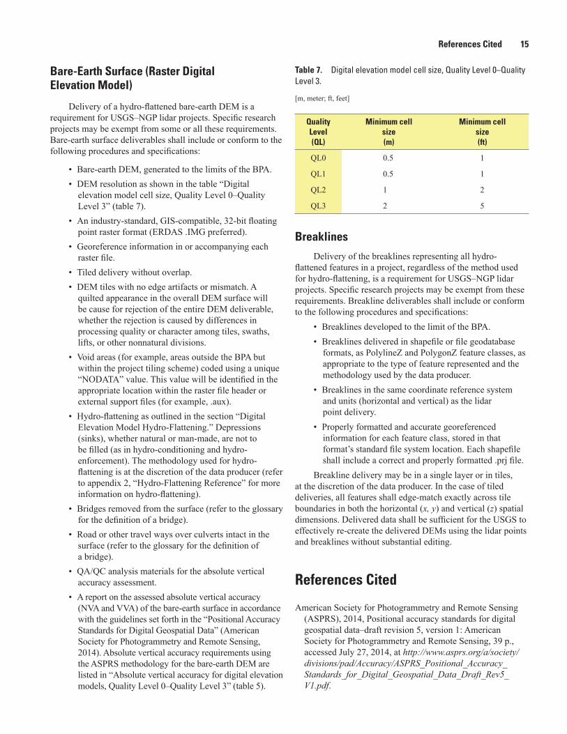
Bare-Earth Surface (Raster Digital Elevation Model)
Delivery of a hydro-flattened bare-earth DEM is a requirement for USGS–NGP lidar projects. Specific research projects may be exempt from some or all these requirements. Bare-earth surface deliverables shall include or conform to the following procedures and specifications:
• Bare-earth DEM, generated to the limits of the BPA.• DEM resolution as shown in the table “Digital
elevation model cell size, Quality Level 0–Quality Level 3” (table 7).
• An industry-standard, GIS-compatible, 32-bit floating point raster format (ERDAS .IMG preferred).
• Georeference information in or accompanying each raster file.
• Tiled delivery without overlap. • DEM tiles with no edge artifacts or mismatch. A
quilted appearance in the overall DEM surface will be cause for rejection of the entire DEM deliverable, whether the rejection is caused by differences in processing quality or character among tiles, swaths, lifts, or other nonnatural divisions.
• Void areas (for example, areas outside the BPA but within the project tiling scheme) coded using a unique “NODATA” value. This value will be identified in the appropriate location within the raster file header or external support files (for example, .aux).
• Hydro-flattening as outlined in the section “Digital Elevation Model Hydro-Flattening.” Depressions (sinks), whether natural or man-made, are not to be filled (as in hydro-conditioning and hydro-enforcement). The methodology used for hydro-flattening is at the discretion of the data producer (refer to appendix 2, “Hydro-Flattening Reference” for more information on hydro-flattening).
• Bridges removed from the surface (refer to the glossary for the definition of a bridge).
• Road or other travel ways over culverts intact in the surface (refer to the glossary for the definition of a bridge).
• QA/QC analysis materials for the absolute vertical accuracy assessment.
• A report on the assessed absolute vertical accuracy (NVA and VVA) of the bare-earth surface in accordance with the guidelines set forth in the “Positional Accuracy Standards for Digital Geospatial Data” (American Society for Photogrammetry and Remote Sensing, 2014). Absolute vertical accuracy requirements using the ASPRS methodology for the bare-earth DEM are listed in “Absolute vertical accuracy for digital elevation models, Quality Level 0–Quality Level 3” (table 5).
Table 7. Digital elevation model cell size, Quality Level 0–Quality Level 3.
[m, meter; ft, feet]
Quality Level (QL)
Minimum cell size (m)
Minimum cell size (ft)
QL0 0.5 1
QL1 0.5 1
QL2 1 2
QL3 2 5
Breaklines
Delivery of the breaklines representing all hydro-flattened features in a project, regardless of the method used for hydro-flattening, is a requirement for USGS–NGP lidar projects. Specific research projects may be exempt from these requirements. Breakline deliverables shall include or conform to the following procedures and specifications:
• Breaklines developed to the limit of the BPA.• Breaklines delivered in shapefile or file geodatabase
formats, as PolylineZ and PolygonZ feature classes, as appropriate to the type of feature represented and the methodology used by the data producer.
• Breaklines in the same coordinate reference system and units (horizontal and vertical) as the lidar point delivery.
• Properly formatted and accurate georeferenced information for each feature class, stored in that format’s standard file system location. Each shapefile shall include a correct and properly formatted .prj file.
Breakline delivery may be in a single layer or in tiles, at the discretion of the data producer. In the case of tiled deliveries, all features shall edge-match exactly across tile boundaries in both the horizontal (x, y) and vertical (z) spatial dimensions. Delivered data shall be sufficient for the USGS to effectively re-create the delivered DEMs using the lidar points and breaklines without substantial editing.
References Cited
American Society for Photogrammetry and Remote Sensing (ASPRS), 2014, Positional accuracy standards for digital geospatial data–draft revision 5, version 1: American Society for Photogrammetry and Remote Sensing, 39 p., accessed July 27, 2014, at http://www.asprs.org/a/society/divisions/pad/Accuracy/ASPRS_Positional_Accuracy_Standards_for_Digital_Geospatial_Data_Draft_Rev5_V1.pdf.

16 Lidar Base Specification
American Society for Photogrammetry and Remote Sensing (ASPRS), 2011, LAS specification version 1.4–R13: Bethesda, Md., American Society for Photogrammetry and Remote Sensing, 27 p. [Also available at http://www.asprs.org/Committee-General/LASer-LAS-File-Format-Exchange-Activities.html.]
American Society for Photogrammetry and Remote Sensing (ASPRS), 2004, Vertical accuracy reporting for lidar, version 1.0: American Society for Photogrammetry and Remote Sensing, 20 p. [Also available at http://www.asprs.org/a/society/committees/lidar/Downloads/Vertical_Accuracy_Reporting_for_Lidar_Data.pdf.]
American Society for Photogrammetry and Remote Sensing (ASPRS), 1990, Accuracy standards for large-scale maps: Bethesda, Md., American Society for Photogrammetry and Remote Sensing, 3 p. [Also available at http://www.asprs.org/a/society/committees/standards/1990_jul_1068-1070.pdf.]
Dewberry, 2012, National enhanced elevation assessment: Fairfax, Va., Dewberry, 871 p. [Also available at http://www.dewberry.com/Consultants/GeospatialMapping/FinalReport-NationalEnhancedElevationAssessment.]
Federal Emergency Management Agency (FEMA), 2002, Guidelines and specifications for flood hazard mapping partners, appendix A—Guidance for aerial mapping and surveying (revised April 2003): Federal Emergency Management Agency, 57 p., accessed June 2, 2014, at http://www.fema.gov/media-library-data/1387814416677-caa613eeca53246cb7a7dcbf342a7197/Guidelines+and+Specifications+for+Flood+Hazard+Mapping+Partners+Appendix+A-Guidance+for+Aerial+Mapping+and+Surveying+(Apr+2003).pdf.
Federal Geographic Data Committee (FGDC), 1998, Geospatial positioning accuracy standards, part 3—National standard for spatial data accuracy: Federal Geographic Data Committee, Subcommittee for Base Cartographic Data, FGDC-STD-007.3–1998, 20 p. [Also available at https://www.fgdc.gov/standards/projects/FGDC-standards-projects/accuracy/part3/chapter3.]
Gesch, D.B., 2007, The national elevation dataset, chap. 4, in Maune, D.F., ed., Digital elevation model technologies and applications—the DEM users manual (2nd ed.): Bethesda, Md., American Society for Photogrammetry and Remote Sensing, p. 99–118. [Also available at http://topotools.cr.usgs.gov/pdfs/Gesch_Chp_4_Nat_Elev_Data_2007.pdf.]
Maune, D.F., 2007, Definitions in digital elevation model technologies and applications—The DEM users manual (2nd ed.): Bethesda, Md., American Society for Photogrammetry and Remote Sensing (ASPRS), p. 550–551.
National Digital Elevation Program (NDEP), 2004, Guidelines for digital elevation data, version 1: National Digital Elevation Program, 93 p. [Also available at http://www.ndep.gov/NDEP_Elevation_Guidelines_Ver1_10May2004.pdf.]
Obama, Barack, 2013, Making open and machine readable the new default for Government information: Federal Register, v. 78, no. 93, 3 p., accessed July 30, 2014. [Also available at http://www.gpo.gov/fdsys/pkg/FR-2013-05-14/pdf/2013-11533.pdf.]
Stoker, J.M., 2013, Are we moving past the pixel? The Third Dimension in National Landscape Mapping: Photogrammetric Engineering and Remote Sensing, 79, no. 2, p. 133–134.

Glossary 17
Glossary
Note: Many of the following definitions are from Maune (2007) and American Society for Photogrammetry and Remote Sensing (2014) and are used with permission.
A
accuracy The closeness of an estimated value (for example, measured or computed) to a standard or accepted (true) value of a particular quantity. See precision.
• absolute accuracy A measure that accounts for all systematic and random errors in a dataset. Absolute accuracy is stated with respect to a defined datum or reference system.
• accuracyr (ACCr) The National Standards for Spatial Data Accuracy (NSSDA) (Federal Geographic Data Committee, 1998) reporting standard in the horizontal component that equals the radius of a circle of uncertainty, such that the true or theoretical horizontal location of the point falls within that circle 95 percent of the time. ACC RMSEr r= ×1 7308. .
• accuracyz (ACCz) The NSSDA reporting standard in the vertical component that equals the linear uncertainty value, such that the true or theoretical vertical location of the point falls within that linear uncertainty value 95 percent of the time. ACC RMSEz z= ×1 9600. .
• horizontal accuracy The horizontal (radial) component of the positional accuracy of a dataset with respect to a horizontal datum, at a specified confidence level. See accuracyr.
• local accuracy The uncertainty in the coordinates of points with respect to coordinates of other directly connected, adjacent points at the 95-percent confidence level.
• network accuracy The uncertainty in the coordinates of mapped points with respect to the geodetic datum at the 95-percent confidence level.
• positional accuracy The accuracy at the 95-percent confidence level of the position of features, including horizontal and vertical positions, with respect to horizontal and vertical datums.
• relative accuracy A measure of variation in point-to-point accuracy in a data set. In lidar, this term may also specifically mean the positional agreement between points within a swath, adjacent swaths within a lift, adjacent lifts within a project, or between adjacent projects.
• vertical accuracy The measure of the positional accuracy of a data set with respect to a specified vertical datum, at a specified confidence level or percentile. See accuracyz.
aggregate nominal pulse density (ANPD) A variant of nominal pulse density that expresses the total expected or actual density of pulses occurring in a specified unit area resulting from multiple passes of the light detection and ranging (lidar) instrument, or a single pass of a plat-form with multiple lidar instruments, over the same target area. In all other respects, ANPD is identical to nominal pulse density (NPD). In single coverage collection, ANPD and NPD will be equal. See aggregate nominal pulse spacing, nominal pulse density, nominal pulse spacing.aggregate nominal pulse spacing (ANPS) A variant of nominal pulse spacing that expresses the typical or average lateral distance between pulses in a lidar dataset resulting from multiple passes of the lidar instrument, or a single pass of a platform with multiple lidar instruments, over the same target area. In all other respects, ANPS is identical to nominal pulse spacing
18 Lidar Base Specification
(NPS). In single coverage collections, ANPS and NPS will be equal. See aggregate nominal pulse density, nominal pulse density, nominal pulse spacing.artifacts An inaccurate observation, effect, or result, especially one resulting from the tech-nology used in scientific investigation or from experimental error. In bare-earth elevation mod-els, artifacts are detectable surface remnants of buildings, trees, towers, telephone poles or other elevated features; also, detectable artificial anomalies that are introduced to a surface model by way of system specific collection or processing techniques. For example, corn-row effects of profile collection, star and ramp effects from multidirectional contour interpolation, or detect-able triangular facets caused when vegetation canopies are removed from lidar data.attitude The position of a body defined by the angles between the axes of the coordinate system of the body and the axes of an external coordinate system. In photogrammetry, the attitude is the angular orientation of a camera (roll, pitch, yaw), or of the photograph taken with that camera, with respect to some external reference system. With lidar, the attitude is normally defined as the roll, pitch and heading of the instrument at the instant an active pulse is emitted from the sensor.
B
bald earth Nonpreferred term. See bare earth.bare earth (bare-earth) Digital elevation data of the terrain, free from vegetation, buildings and other man-made structures. Elevations of the ground.blunder A mistake resulting from carelessness or negligence.boresight Calibration of a lidar sensor system equipped with an Inertial Measurement Unit (IMU) and global positioning system (GPS) to determine or establish the accurate:
• Position of the instrument (x, y, z) with respect to the GPS antenna, and
• Orientation (roll, pitch, heading) of the lidar instrument with respect to straight and level flight.
breakline A linear feature that describes a change in the smoothness or continuity of a sur-face. The two most common forms of breaklines are as follows:
• A soft breakline ensures that known z values along a linear feature are maintained (for example, elevations along a pipeline, road centerline or drainage ditch), and ensures that linear features and polygon edges are maintained in a triangulated irregular network (TIN) surface model, by enforcing the breaklines as TIN edges. They are generally synonymous with three-dimensional (3D) breaklines because they are depicted with series of x, y, z coordinates. Somewhat rounded ridges or the trough of a drain may be collected using soft breaklines.
• A hard breakline defines interruptions in surface smoothness (for example, to define streams, rivers, shorelines, dams, ridges, building footprints, and other locations) with abrupt surface changes. Although some hard breaklines are 3D breaklines, they are typically depicted as two-dimensional (2D) breaklines because features such as shorelines and building footprints are normally depicted with series of x, y coordinates only, often digitized from digital orthophotos that include no elevation data.
bridge A structure carrying a road, path, railroad, canal, aircraft taxiway, or any other transit between two locations of higher elevation over an area of lower elevation. A bridge may tra-verse a river, ravine, road, railroad, or other obstacle. “Bridge” also includes but is not limited to aqueduct, drawbridge, flyover, footbridge, overpass, span, trestle, and viaduct. In mapping, the term “bridge” is distinguished from a roadway over a culvert in that a bridge is a man-made, elevated deck which is not underlain with earth or soil. See culvert.
Glossary 19
C
calibration (lidar systems) The process of identifying and correcting for systematic errors in hardware, software, or data. Determining the systematic errors in a measuring device by comparing its measurements with the markings or measurements of a device that is considered correct. Lidar system calibration falls into two main categories:
• instrument calibration Factory calibration includes radiometric and geometric calibration unique to each manufacturer’s hardware, and tuned to meet the performance specifications for the model being calibrated. Instrument calibration can only be assessed and corrected by the instrument manufacturer.
• data calibration The lever arm calibration determines the sensor-to-GPS-antenna offset vector (the lever arm) components relative to the antenna phase center. The offset vector components are redeterminded each time the sensor or aircraft GPS antenna is moved or repositioned. Because normal aircraft operations can induce slight variations in component mounting, the components are normally field calibrated for each project, or even daily, to determine corrections to the roll, pitch, yaw, and scale calibration parameters.
calibration point Nonpreferred term. See control point. cell (pixel) A single element of a raster dataset. Each cell contains a single numeric value of information representative of the area covered by the cell. Although the terms “cell” and “pixel” are synonymous, in this specification “cell” is used in reference to non-image rasters such as digital elevation models (DEMs), whereas “pixel” is used in reference to image rasters such as lidar intensity images.check point (checkpoint) A surveyed point used to estimate the positional accuracy of a geo-spatial dataset against an independent source of greater accuracy. Check points are independent from, and may never be used as, control points on the same project.classification (of lidar) The classification of lidar point cloud returns in accordance with a classification scheme to identify the type of target from which each lidar return is reflected. The process allows future differentiation between bare-earth terrain points, water, noise, vegetation, buildings, other man-made features and objects of interest. confidence level The percentage of points within a dataset that are estimated to meet the stated accuracy; for example, accuracy reported at the 95-percent confidence level means that 95 percent of the positions in the data set will have an error with respect to true ground position that are equal to or smaller than the reported accuracy value.consolidated vertical accuracy (CVA) Replaced by the term vegetated vertical accuracy (VVA) in this specification, CVA is the term used by the National Digital Elevation Program (NDEP) guidelines for vertical accuracy at the 95th percentile in all land cover categories com-bined (National Digital Elevation Program, 2004). See percentile, vegetated vertical accuracy.control point (calibration point) A surveyed point used to geometrically adjust a lidar dataset to establish its positional accuracy relative to the real world. Control points are independent from, and may never be used as, check points on the same project. CONUS Conterminous United States, the 48 states.culvert A tunnel carrying a stream or open drainage under a road or railroad, or through another type of obstruction to natural drainage. Typically, constructed of formed concrete or corrugated metal and surrounded on all sides, top, and bottom by earth or soil.
D
data void In lidar, a gap in the point cloud coverage, caused by surface nonreflectance of the lidar pulse, instrument or processing anomalies or failure, obstruction of the lidar pulse, or improper collection flight planning. Any area greater than or equal to (four times the aggregate nominal pulse spacing [ANPS]) squared, measured using first returns only, is considered to be a data void.

20 Lidar Base Specification
datum A set of reference points on the Earth’s surface against in which position measure-ments are made, and (usually) an associated model of the shape of the Earth (reference ellip-soid) to define a geographic coordinate system. Horizontal datums (for example, the North American Datum of 1983 [NAD 83]) are used for describing a point on the Earth’s surface, in latitude and longitude or another coordinate system. Vertical datums (for example, the North American Vertical Datum of 1988 [NAVD 88]) are used to measure elevations or depths. In engineering and drafting, a datum is a reference point, surface, or axis on an object against which measurements are made. digital elevation model (DEM) See four different definitions below:
• A popular acronym used as a generic term for digital topographic and bathymetric data in all its various forms. Unless specifically referenced as a digital surface model (DSM), the generic DEM normally implies x, y coordinates and z values of the bare-earth terrain, void of vegetation and manmade features.
• As used by the U.S. Geological Survey (USGS), a DEM is the digital cartographic representation of the elevation of the land at regularly spaced intervals in x and y directions, using z values referenced to a common vertical datum.
• As typically used in the United States and elsewhere, a DEM has bare-earth z values at regularly spaced intervals in x and y directions; however, grid spacing, datum, coordinate systems, data formats, and other characteristics may vary widely.
• A “D-E-M” is a specific raster data format once widely used by the USGS. These DEMs are a sampled array of elevations for a number of ground positions at regularly spaced intervals.
digital elevation model (DEM) resolution The linear size of each cell of a raster DEM. Fea-tures smaller than the cell size cannot be explicitly represented in a raster model. DEM resolu-tion may also be referred to as cell size, grid spacing, or ground sample distance.digital surface model (DSM) Similar to digital elevation models (DEMs) except that they may depict the elevations of the top surfaces of buildings, trees, towers, and other features elevated above the bare earth. Lidar DSMs are especially relevant for telecommunications management, air safety, forest management, and 3D modeling and simulation.digital terrain model (DTM) See two different definitions below:
• In some countries, DTMs are synonymous with DEMs, representing the bare-earth terrain with uniformly-spaced z values, as in a raster.
• As used in the United States, a “DTM” is a vector dataset composed of 3D breaklines and regularly spaced 3D mass points, typically created through stereo photogrammetry, that characterize the shape of the bare-earth terrain. Breaklines more precisely delineate linear features whose shape and location would otherwise be lost. A DTM is not a surface model; its component elements are discrete and not continuous; a TIN or DEM surface must be derived from the DTM. Surfaces derived from DTMs can represent distinctive terrain features much better than those generated solely from gridded elevation measurements. A lidar point dataset combined with ancillary breaklines is also considered a DTM.
discrete return lidar Lidar system or data in which important peaks in the waveform are captured and stored. Each peak represents a return from a different target, discernible in vertical or horizontal domains. Most modern lidar systems are capable of capturing multiple discrete returns from each emitted laser pulse. See waveform lidar.
E
elevation The distance measured upward along a plumb line between a point and the geoid. The elevation of a point is normally the same as its orthometric height, defined as H in the equation: H h N= − , where h is equal to the ellipsoid height and N is equal to the geoid height.
Glossary 21
F
first return (first-return) The first important measurable part of a return lidar pulse.flightline A single pass of the collection aircraft over the target area. Commonly misused to refer to the data resulting from a flightline of collection. See swath.fundamental vertical accuracy (FVA) Replaced by the term nonvegetated vertical accuracy (NVA), in this specification, FVA is the term used by the NDEP guidelines for vertical accuracy at the 95-percent confidence level in open terrain only where errors should approximate a nor-mal error distribution. See nonvegetated vertical accuracy, accuracy, confidence level.
G
geographic information system (GIS) A system of spatially referenced information, including computer programs that acquire, store, manipulate, analyze, and display spatial data. geospatial data Information that identifies the geographic location and characteristics of natural or constructed features and boundaries of earth. This information may be derived from—among other things— remote-sensing, mapping, and surveying technologies. Geospatial data generally are considered to be synonymous with spatial data. However, the former always is associated with geographic or Cartesian coordinates linked to a horizontal or vertical datum, whereas the latter (for example, generic architectural house plans) may include dimensions and other spatial data not linked to any physical location. ground truth Verification of a situation, without errors introduced by sensors or human per-ception and judgment.
H
hillshade A function used to create an illuminated representation of the surface, using a hypo-thetical light source, to enhance terrain visualization effects.horizontal accuracy Positional accuracy of a dataset with respect to a horizontal datum. According to the NSSDA, horizontal (radial) accuracy at the 95-percent confidence level is defined as ACCr.hydraulic modeling The use of digital elevation data, rainfall-runoff data from hydrologic models, surface roughness data, and information on hydraulic structures (for example, bridges, culverts, dams, weirs, and sewers) to predict flood levels and manage water resources. Hydrau-lic models are based on computations involving liquids under pressure and many other defini-tions of hydraulic modeling exist that are not associated with terrain elevations, for example, modeling of hydraulic lines in aircraft and automobiles. hydrologic modeling The computer modeling of rainfall and the effects of land cover, soil conditions, and terrain slope to estimate rainfall runoff into streams, rivers, and lakes. Digital elevation data are used as part of hydrologic modeling.hydrologically conditioned (hydro-conditioned) Processing of a DEM or TIN so that the flow of water is continuous across the entire terrain surface, including the removal of all isolated sinks or pits. The only sinks that are retained are the real ones on the landscape. Whereas hydrologically enforced is relevant to drainage features that generally are mapped, hydrologi-cally conditioned is relevant to the entire land surface and is done so that water flow is continu-ous across the surface, whether that flow is in a stream channel or not. The purpose for continu-ous flow is so that relations and (or) links among basins and (or) catchments can be known for large areas.hydrologically flattened (hydro-flattened) Processing of a lidar-derived surface (DEM or TIN) so that mapped water bodies, streams, rivers, reservoirs, and other cartographically polygonal water surfaces are flat and, where appropriate, level from bank-to-bank. Additionally, surfaces of streams, rivers, and long reservoirs demonstrate a gradient change in elevation along their length, consistent with their natural behavior and the surrounding topography. In traditional maps that are compiled photogrammetrically, this process is accomplished automatically through the inclusion of measured breaklines in the DTM. However, because lidar does not
22 Lidar Base Specification
inherently include breaklines, a DEM or TIN derived solely from lidar points will depict water surfaces with unsightly and unnatural artifacts of triangulation. The process of hydro-flattening typically involves the addition of breaklines along the banks of specified water bodies, streams, rivers, and ponds. These breaklines establish elevations for the water surfaces that are consis-tent with the surrounding topography, and produce aesthetically acceptable water surfaces in the final DEM or TIN. Unlike hydro-conditioning and hydro-enforcement, hydro-flattening is not driven by any hydrologic or hydraulic modeling requirements, but solely by cartographic mapping needs.hydrologically enforced (hydro-enforced) Processing of mapped water bodies so that lakes and reservoirs are level and so that streams and rivers flow downhill. For example, a DEM, TIN or topographic contour dataset with elevations removed from the tops of selected drain-age structures (bridges and culverts) so as to depict the terrain under those structures. Hydro-enforcement enables hydrologic and hydraulic models to depict water flowing under these structures, rather than appearing in the computer model to be dammed by them because of road deck elevations higher than the water levels. Hydro-enforced TINs also use breaklines along shorelines and stream centerlines, for example, where these breaklines form the edges of TIN triangles along the alignment of drainage features. Shore breaklines for streams and rivers would be 3D breaklines with elevations that decrease as the stream flows downstream; however, shore breaklines for lakes or reservoirs would have the same elevation for the entire shoreline if the water surface is known or assumed to be level throughout.I
intensity (lidar) For discrete-return lidar instruments, intensity is the recorded amplitude of the reflected lidar pulse at the moment the reflection is captured as a return by the lidar instru-ment. Lidar intensity values can be affected by many factors, such as the instantaneous setting of the instrument’s automatic gain control and angle of incidence and cannot be equated to a true measure of energy. In full-waveform systems, the entire reflection is sampled and recorded, and true energy measurements can be made for each return or overall reflection. Intensity val-ues for discrete returns derived from a full-waveform system may or may not be calibrated to represent true energy.
Lidar intensity data make it possible to map variable textures in the form of a gray-scale image. Intensity return data enable automatic identification and extraction of objects such as buildings and impervious surfaces, and can aid in lidar point classification. In spite of their similar appearance, lidar intensity images differ from traditional panchromatic images in several important ways:
• Lidar intensity is a measure of the reflection of an active laser energy source, not natural solar energy.
• Lidar intensity images are aggregations of values at point samples. The value of a pixel does not represent the composite value for the area of that pixel.
• Lidar intensity images depict the surface reflectivity within an extremely narrow band of the infra-red spectrum, not the entire visible spectrum as in panchromatic images.
• Lidar intensity images are strongly affected by the angle of incidence of the laser to the target, and are subject to unnatural shadowing artifacts.
• The values on which lidar intensity images are based may or may not be calibrated to any standard reference. Intensity images usually contain wide variation of values within swaths, between swaths, and between lifts.
For these reasons, lidar intensity images must be interpreted and analyzed with unusually high care and skill.
L
LAS A public file format for the interchange of 3D point cloud data between data users. The file extension is .las.
Glossary 23
last return The last important measurable part of a return lidar pulse.lattice A 3D vector representation method created by a rectangular array of points spaced at a constant sampling interval in x and y directions relative to a common origin. A lattice differs from a grid in that it represents the value of the surface only at the lattice mesh points rather than the elevation of the cell area surrounding the centroid of a grid cell.lever arm A relative position vector of one sensor with respect to another in a direct georefer-encing system. For example, with aerial mapping cameras, lever arms are positioned between the inertial center of the IMU and the phase center of the GPS antenna, each with respect to the camera perspective center within the lens of the camera.lidar An instrument that measures distance to a reflecting object by emitting timed pulses of light and measuring the time difference between the emission of a laser pulse and the recep-tion of the pulse’s reflection(s). The measured time interval for each reflection is converted to distance, which when combined with position and attitude information from GPS, IMU, and the instrument itself, allows the derivation of the 3D-point location of the reflecting target’s loca-tion.lift A lift is a single takeoff and landing cycle for a collection platform (fixed or rotary wing) within an aerial data collection project, often lidar. local accuracy See accuracy.
M
metadata Any information that is descriptive or supportive of a geospatial dataset, including formally structured and formatted metadata files (for example, eXtensible Markup Language [XML]-formatted Federal Geographic Data Committee [FGDC] metadata), reports (collection, processing, quality assurance/quality control [QA/QC]), and other supporting data (for exam-ple, survey points, shapefiles).
N
nominal pulse density (NPD) A common measure of the density of a lidar dataset; NPD is the typical or average number of pulses occurring in a specified areal unit. The NPD is typically expressed as pulses per square meter (pls/m2). This value is predicted in mission planning and empirically calculated from the collected data, using only the first (or last) return points as sur-rogates for pulses. As used in this specification, NPD refers to single swath, single instrument data, whereas aggregate nominal pulse density describes the overall pulse density resulting from multiple passes of the lidar instrument, or a single pass of a platform with multiple lidar instruments, over the same target area. The term NPD is more commonly used in high-density collections (greater than 1 pls/m2), with its inverse, nominal pulse spacing (NPS), being used in low-density collections (less than or equal to 1 pls/m2). Assuming meters are being used in both expressions, NPD can be calculated from NPS using the formula NPD NPS=1 2/ . See aggre-gate nominal pulse density, aggregate nominal pulse spacing, nominal pulse spacing.nominal pulse spacing (NPS) A common measure of the density of a lidar dataset, NPS the typical or average lateral distance between pulses in a lidar dataset, typically expressed in meters and most simply calculated as the square root of the average area per first return point. This value is predicted in mission planning and empirically calculated from the collected data, using only the first (or last) return points as surrogates for pulses. As used in this specification, NPS refers to single swath, single instrument data, whereas aggregate nominal pulse spacing describes the overall pulse spacing resulting from multiple passes of the lidar instrument, or a single pass of a platform with multiple lidar instruments, over the same target area. The term NPS is more commonly used in low-density collections (greater than or equal to 1 meter NPS) with its inverse, nominal pulse density (NPD), being used in high-density collections (less than 1 meter NPS). Assuming meters are being used in both expressions, NPS can be calculated from NPD using the formula . See aggregate nominal pulse density, aggregate nominal pulse spacing, nominal pulse density.
NPS NPD= 1/
24 Lidar Base Specification
nonvegetated vertical accuracy (NVA) Replaces fundamental vertical accuracy (FVA). The vertical accuracy at the 95-percent confidence level in nonvegetated open terrain, where errors should approximate a normal distribution. See fundamental vertical accuracy.
O
overage Those parts of a swath that are not necessary to form a complete single, non-over-lapped, gap-free coverage with respect to the adjacent swaths. The non-tenderloin parts of a swath. In collections designed using multiple coverage, overage are the parts of the swath that are not necessary to form a complete non-overlapped coverage at the planned depth of cover-age. In the LAS Specification version 1.4 (American Society for Photogrammetry and Remote Sensing, 2011), these points are identified by using the incorrectly named “overlap” bit flag. See overlap, tenderloin.overlap Any part of a swath that also is covered by any part of any other swath. The term overlap is incorrectly used in the LAS Specification version 1.4 (American Society for Photo-grammetry and Remote Sensing, 2011) to describe the flag intended to identify overage points. See overage, tenderloin.
P
percentile A measure used in statistics indicating the value below which a given percentage of observations (absolute values of errors) in a group of observations fall. For example, the 95th percentile is the value (or score) below which 95 percent of the observations may be found.
• There are different approaches to determining percentile ranks and associated values. This specification recommends the use of the following equations for computing percentile rank and percentile as the most appropriate for estimating the VVA. Note that percentile calculations are based on the absolute values of the errors, as it is the magnitude of the errors, not the sign that is of concern.
• The percentile rank (n) is first calculated for the desired percentile using the following equation:
n P N=
× −( )
+
100
1 1 (1)
where n is the rank of the observation that contains the Pth percentile, P is the proportion (of 100) at which the percentile is desired (for example, 95 for
95th percentile), N is the number of observations in the sample data set.
• Once the rank of the observation is determined, the percentile (Qp) can then be interpolated from the upper and lower observations using the following equation:
Q A n n A n A np w d w w= [ ]+ × +[ ]− [ ]( )( )( )1 (2)
where Qp is the Pth percentile; the value at rank n, A is an array of the absolute values of the samples, indexed in ascending order
from 1 to N, A[i] is the sample value of array A at index i (for example, nw or nd). i must be an
integer between 1 and N, n is the rank of the observation that contains the Pth percentile, nw is the whole number component of n (for example, 3 of 3.14), nd is the decimal component of n (for example, 0.14 of 3.14).
Glossary 25
pixel See cell.point classification The assignment of a target identity classification to a particular lidar point or group of points. point cloud One of the fundamental types of geospatial data (others being vector and raster), a point cloud is a large set of three dimensional points, typically from a lidar collection. As a basic GIS data type, a point cloud is differentiated from a typical point dataset in several key ways:
• Point clouds are almost always 3D,
• Pint clouds have an order of magnitude more features than point datasets, and
• Individual point features in point clouds do not typically possess individually meaningful attributes; the informational value in a point cloud is derived from the relations among large numbers of features.
See raster, vector.precision (repeatability) The closeness with which measurements agree with each other, even though they may all contain a systematic bias. See accuracy.point family The complete set of multiple returns reflected from a single lidar pulse.preprocessing In lidar, the preprocessing of data most commonly refers to those steps used in converting the collected GPS, IMU, instrument, and ranging information into an interpretable x, y, z point cloud, including generation of trajectory information, calibration of the dataset, and controlling the dataset to known ground references.post processing In lidar, post processing refers to the processing steps applied to lidar data point clouds, including point classification, feature extraction (for example, building footprints, hydrographic features, and others), tiling, and generation of derivative products (DEMs, DSMs, intensity images, and others).
R
raster One of the fundamental types of geospatial data (others being vector and point cloud), a raster is an array of cells (or pixels) that each contain a single piece of numeric information representative of the area covered by the cell. Raster datasets are spatially continuous; with respect to DEMs this quality creates a surface from which information can be extracted from any location. As spatial arrays, rasters are always rectangular; cells are most often square. Co-located rasters can be stored in a single file as layers, as with color digital images. See raster, vector.resolution The smallest unit a sensor can detect or the smallest unit a raster DEM depicts. The degree of fineness to which a measurement can be made. Resolution is also used to describe the linear size of an image pixel or raster cell.root mean square difference (RMSD) The square root of the average of the set of squared differences between two dataset coordinate values taken at identical locations. The term RMSD differentiates from root mean square error (RMSE) because neither dataset is known to be more or less accurate and the differences cannot be regarded as errors. An RMSD value is used in lidar when assessing the differences between two overlapping swaths of data. See RMSE.
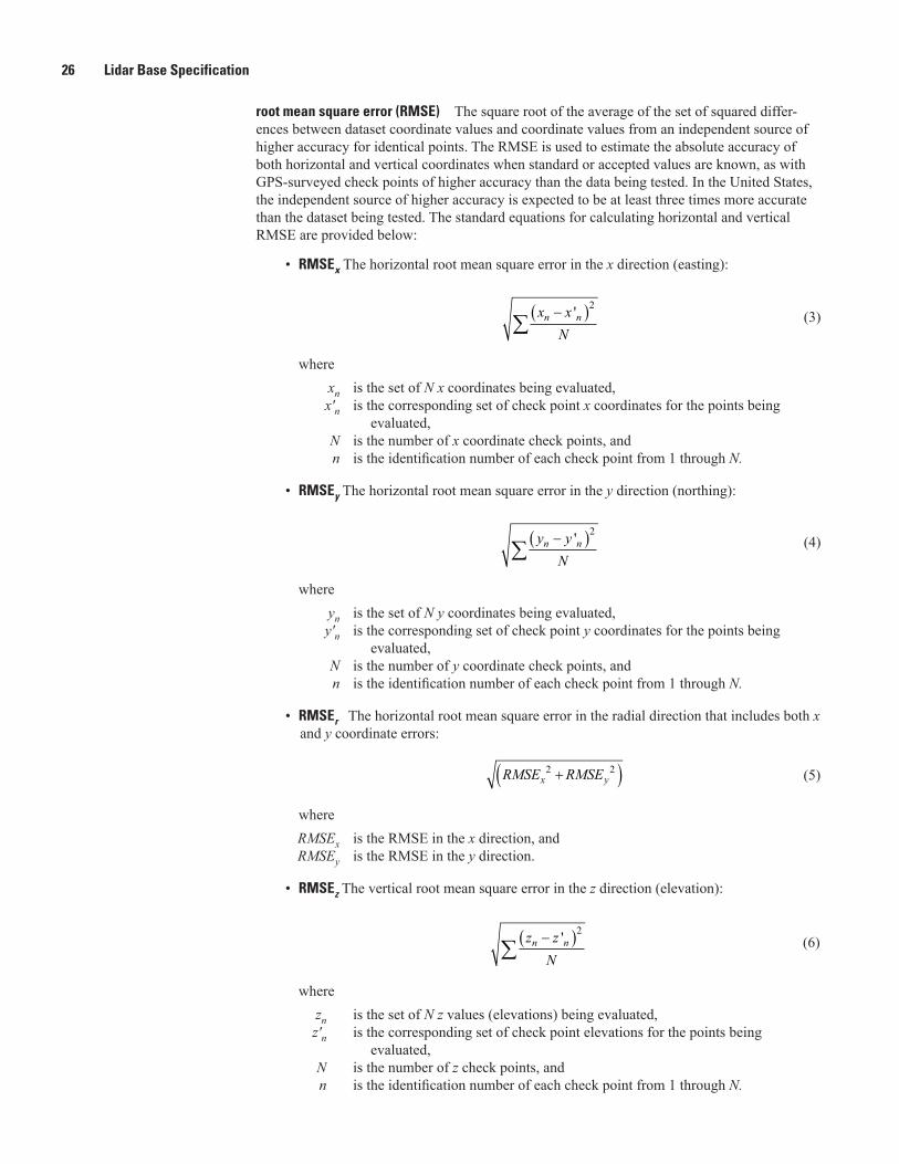
26 Lidar Base Specification
root mean square error (RMSE) The square root of the average of the set of squared differ-ences between dataset coordinate values and coordinate values from an independent source of higher accuracy for identical points. The RMSE is used to estimate the absolute accuracy of both horizontal and vertical coordinates when standard or accepted values are known, as with GPS-surveyed check points of higher accuracy than the data being tested. In the United States, the independent source of higher accuracy is expected to be at least three times more accurate than the dataset being tested. The standard equations for calculating horizontal and vertical RMSE are provided below:
• RMSEx The horizontal root mean square error in the x direction (easting):
∑−( )x xN
n n'2
(3)
where xn is the set of N x coordinates being evaluated, x′n is the corresponding set of check point x coordinates for the points being
evaluated, N is the number of x coordinate check points, and n is the identification number of each check point from 1 through N.
• RMSEy The horizontal root mean square error in the y direction (northing):
∑−( )y yN
n n'2
(4)
where yn is the set of N y coordinates being evaluated, y′n is the corresponding set of check point y coordinates for the points being
evaluated, N is the number of y coordinate check points, and n is the identification number of each check point from 1 through N.
• RMSEr The horizontal root mean square error in the radial direction that includes both x and y coordinate errors:
RMSE RMSEx y2 2+( )� (5)
where RMSEx is the RMSE in the x direction, and RMSEy is the RMSE in the y direction.
• RMSEz The vertical root mean square error in the z direction (elevation):
∑−( )z zN
n n'2
(6)
where zn is the set of N z values (elevations) being evaluated, z′n is the corresponding set of check point elevations for the points being
evaluated, N is the number of z check points, and n is the identification number of each check point from 1 through N.
Glossary 27
S
spatial distribution In lidar, the regularity or consistency of the point density within the col-lection. The theoretical ideal spatial distribution for a lidar collection is a perfect regular lattice of points with equal spacing on x and y axes. Various factors prevent this ideal from being achieved, including the following factors:
• Instrument design (oscillating mirrors),
• Mission planning (difference between along-track and cross-track pulse spacing), and
• In-flight attitude variations (roll, pitch, and yaw).standard deviation A measure of spread or dispersion of a sample of errors around the sample mean error. It is a measure of precision, rather than accuracy; the standard deviation does not account for uncorrected systematic errors.supplemental vertical accuracy (SVA) Merged into the vegetated vertical accuracy (VVA) in this specification, SVA is the NDEP guidelines term for reporting the vertical accuracy at the 95th percentile in each separate land cover category where vertical errors may not follow a normal error distribution. See percentile, vegetated vertical accuracy.swath The data resulting from a single flightline of collection. See flightline.systematic error An error whose algebraic sign and, to some extent, magnitude bears a fixed relation to some condition or set of conditions. Systematic errors follow some fixed pattern and are introduced by data collection procedures, processing or given datum.
T
tenderloin The central part of the swath that, when combined with adjacent swath tenderloins, forms a complete, single, non-overlapped, gap-free coverage. In collections designed using multiple coverage, tenderloins are the parts of the swath necessary to form a complete non-overlapped, gap-free coverage at the planned depth of coverage. See overage, overlap.triangulated irregular network (TIN) A vector data structure that partitions geographic space into contiguous, non-overlapping triangles. In lidar, the vertices of each triangle are lidar points with x, y, and z values. In most geographic applications, TINs are based on Delaunay triangula-tion algorithms in which no point in any given triangle lies within the circumcircle of any other triangle.
U
uncertainty (of measurement) a parameter that characterizes the dispersion of measured val-ues, or the range in which the “true” value most likely lies. It can also be defined as an estimate of the limits of the error in a measurement (where “error” is defined as the difference between the theoretically-unknowable “true” value of a parameter and its measured value). Standard uncertainty refers to uncertainty expressed as a standard deviation.
V
vector One of the fundamental types of geospatial data (others being raster and point cloud), vectors include a variety of data structures that are geometrically described by x and y coor-dinates, and potentially z values. Vector data subtypes include points, lines, and polygons. A DTM composed of mass points and breaklines is an example of a vector dataset; a TIN is a vector surface. See point cloud, raster.vegetated vertical accuracy (VVA) Replaces supplemental vertical accuracy (SVA) and consolidated vertical accuracy (CVA). An estimate of the vertical accuracy, based on the 95th percentile, in vegetated terrain where errors do not necessarily approximate a normal distribu-tion. See percentile, nonvegetated vertical accuracy.
28 Lidar Base Specification
W
waveform lidar Lidar system or data in which the entire reflection of the laser pulse is fully digitized, captured, and stored. Discrete return point clouds can be extracted from the wave-form data during post processing. See discrete return lidar.well-distributed For a dataset covering a rectangular area that has uniform positional accu-racy, check points should be distributed so that points are spaced at intervals of at least 10 per-cent of the diagonal distance across the dataset and at least 20 percent of the points are located in each quadrant of the dataset (adapted from the NSSDA of the Federal Geographic Data Com-mittee, 1998). As related to this specification, these guidelines are applicable to each land cover class for which check points are being collected.withheld Within the LAS file specification, a single bit flag indicating that the associated lidar point is geometrically anomalous or unreliable and should be ignored for all normal processes. These points are retained because of their value in specialized analysis. Withheld points typi-cally are identified and tagged during preprocessing or through the use of automatic classifica-tion routines. Examples of points typically tagged as withheld are listed below:
• Spatial outliers in either the horizontal or vertical domains, and
• Geometrically unreliable points near the edge of a swath.
Supplemental InformationUSGS National Elevation Dataset (NED) Web site: http://ned.usgs.gov
MP-Metadata Parser: http://geology.usgs.gov/tools/metadata
FGDC Content Standard for Geospatial Metadata: http://www.fgdc.gov/metadata/csdgm/
National Geodetic Survey, National Adjustment of 2011 Project: http://www.ngs.noaa.gov/web/surveys/NA2011/
National Geodetic Survey, Geoid and Deflection Models: http://www.ngs.noaa.gov/GEOID/models.shtml
Appendix 1 29
Appendix 1. Common Data Upgrades
Appendix 1 contains a partial list of common upgrades, which is neither comprehensive nor exclusive.• Independent third-party quality assurance/quality control (QA/QC) by another contractor. • Full waveform collection and delivery. • Additional environmental constraints:
• Tidal coordination, flood stages, crop or plant growth cycles.• Shorelines corrected for tidal variations within a collection.
• Top-of-Canopy (first return) Raster Surface (tiled):• Raster representing the highest return within each cell is preferred.
• Intensity images (8-bit gray scale, tiled):• Interpolation based on first returns.• Interpolation based on all-returns, summed.
• Detailed classification (additional classes):• Class 3: Low vegetation.• Class 4: Medium vegetation (use for single vegetation class).• Class 5: High vegetation.• Class 6: Buildings, other man-made structures.• Class n: Additional classes or features as agreed upon in advance.
• Hydrologically enforced (Hydro-Enforced) digital elevation models (DEM) as an additional deliverable.
• Hydrologically conditioned (Hydro-Conditioned) DEMs as an additional deliverable.
• Breaklines (PolylineZ and PolygonZ) for additional hydrographic and topographic features:• Narrower double-line streams and rivers.• Single-line streams and rivers.• Smaller ponds.• Culverts and other drainage structures.• Retaining walls.• Hydrologic areas, for example swamp or marsh.• Appropriate integration of additional features into delivered DEMs.
• Extracted buildings (PolygonZ):• Footprints with maximum elevation or height above ground as an attribute.
• Other products as defined by requirements and agreed upon before a funding commitment.
30 Lidar Base Specification
Appendix 2. Hydro-Flattening Reference
The subject of variations of lidar-based digital elevation models (DEM) is somewhat new and substantial diversity exists in the understanding of the topic across the industry. The material in this appendix was developed to provide a definitive reference on the subject only as it relates to the creation of DEMs intended to be integrated into the U.S. Geological Survey (USGS) National Elevation Dataset (NED). The information presented in this appendix is not meant to supplant other reference materials and should not be considered authoritative beyond its intended scope.
As used in this specification, “hydro-flattened” describes the specific type of DEM required by the USGS National Geospatial Program (NGP) for integration into the NED. Hydro-flattening is the process of creating a lidar-derived DEM in which water surfaces appear and behave as they would in traditional topographic DEMs created from photogrammetric digital terrain models (DTMs). A hydro-flattened DEM is a topographic DEM and should not be confused with hydro-enforced or hydro-conditioned DEMs, which are hydrologic surfaces.
Traditionally, topography was depicted using contours on printed maps and, although modern computer technology provides superior alternatives, the contour map remains a popular and widely used product. The NED was initially developed as a topographic DEM from USGS contour maps and it remains the underlying source data for newly generated contours. To ensure that USGS contours continue to present the same type of information as they are updated, DEMs used to update the NED must also possess the same basic character as the existing NED.
A traditional topographic DEM such as the NED represents the actual ground surface, and hydrologic features are handled in established ways. Roadways crossing drainages passing through culverts remain in the surface model because they are part of the landscape (the culvert beneath the road is the manmade feature). Bridges, manmade structures above the landscape, are removed.
For many years, the source data for topographic raster DEMs were mass points and breaklines (collectively referred to as a DTM) compiled through photogrammetric compilation from stereographic aerial imagery. The DTM is converted into a triangulated irregular network (TIN) surface from which a raster DEM could be generated. Photogrammetric DTMs inherently contain breaklines that clearly define the edges of water bodies, coastlines, and single- and double-line stream and rivers. These breaklines force the derived DEM to appear, and contours to behave, in specific ways: water surfaces appear flat, roadways are continuous when on the ground, and rivers are continuous under bridge locations; contours follow water body banks and cross streams are perpendicular to the centerline.
[Note: DEMs developed solely for orthophoto production may include bridges, because their presence prevents distortion in the image and reduces the amount of post processing for corrections of the final orthophotos. These are special use DEMs and are not relevant to this specification.]
Computer technology allows hydraulic and hydrologic modeling to be performed using digital DEM surfaces directly. For these applications, traditional topographic DEMs present a variety of problems that are solved through modification of the DEM surface. The DEM Users’ Manual (Maune, 2007) provides the following definitions related to the adjustment of DEM surfaces for hydrologic analyses:
Hydrologically Conditioned (Hydro-Conditioned) Processing of a DEM or TIN so that the flow of water is continuous across the entire terrain surface, including the removal of all spurious sinks or pits. Whereas “hydrologically-enforced” is relevant to drainage features that are generally mapped, “hydrologically-conditioned” is relevant to the entire land surface and is done so that water flow is continuous across the surface, whether that flow is in a stream channel or not. The purpose for continuous flow is so that relations/links among basins/catchments can be known for large areas. This term is specifically used when describing Elevation Derivatives for National Applications (EDNA), the dataset of NED derivatives made specifically for hydrologic modeling purposes.
Hydrologically Enforced (Hydro-Enforced) Processing of mapped water bodies so that lakes and reservoirs are level and so that streams flow downhill. For example, a DEM, TIN or topographic contour dataset with elevations removed from the tops of selected drainage structures (bridges and culverts) so as to depict the terrain under those structures. Hydro-enforcement enables hydrologic and hydraulic (H&H) models to depict water flowing under these structures, rather than appearing in the computer model to be dammed by them because of road deck elevations higher than the water levels. Hydro-enforced TINs also use breaklines along shorelines and stream centerlines, for example, where these breaklines form the edges of TIN triangles along the alignment of drainage features. Shore breaklines for streams would be 3-D breaklines with elevations that decrease as the stream flows downstream; however, shore breaklines for lakes or reservoirs would have the same elevation for the entire shoreline if the water surface is known or assumed to be level throughout. See
Appendix 2 31
also the definition for “hydrologically-conditioned” that has a slightly different meaning.Hydro-enforcement and hydro-conditioning are important
and useful modifications of the traditional topographic DEM, but they produce hydrologic surfaces that are fundamentally different at a functional level. Hydrologic surfaces are identical to topographic surfaces in many respects but they differ significantly in specific ways. In a topographic DEM, roadways over culverts are included in the surface as part of the landscape. From a hydrologic perspective however, these roadways create artificial impediments (digital dams) to the drainages and introduce sinks (undrained areas) into the landscape. Similarly, topographic DEMs obviously cannot reflect the drainage routes provided by underground storm water systems; hence, topographic DEM surfaces will invariably include other sinks. For topographic mapping, sinks are of no consequence—it is actually desirable to know their locations—but they can introduce errors into hydrologic modeling results.
Unlike the DTM, lidar data consists solely of mass points; breaklines are not automatically created during lidar data collection. Although as mass points, lidar is substantially denser than a photogrammetric DTM, it by itself remains limited in its ability to precisely define the boundaries or locations of distinct linear features such as water bodies, streams, and rivers. The lack of breaklines in the intermediate TIN data structure causes triangulation to occur across water bodies, producing a water surface filled with irregular, unnatural, and visually unappealing triangulation artifacts. These artifacts are then carried into the derived DEM, and ultimately into contours developed from the NED. The representation of random irregular water surfaces in the NED is wholly unacceptable to the USGS–NGP and to users of the NED and its derivatives.
To achieve the same character and appearance of a traditional topographic DEM (or to develop a hydrologically enforced DEM) from lidar source data, breaklines must be developed separately using other techniques. These breaklines are then integrated with lidar points as a complete DTM, or used to modify a DEM previously generated without breaklines.
Hydrologic DEMs usually require flattened water surfaces as well, hence the breaklines required for hydro-flattening the topographic DEM can be equally useful for all DEM types well. See the note, below. Additional breaklines (and lidar point classifications) are needed to efficiently generate hydro-enforced DEMs. If properly attributed, breaklines for all DEM treatments can be stored in a single set of feature classes.
The use of breaklines is the predominant method used for hydro-flattening, though other techniques may exist. The USGS–NGP does not require that breaklines be used for flattening, but does require the delivery of breaklines for all flattened water bodies, and any other breaklines developed for each project. See the section “Digital Elevation Model Hydro-Flattening” for additional information.
[Note: Civil engineers and hydrologists may have requirements for the accuracy of water-surface elevations. With respect to elevation data, the USGS–NGP’s interest is in accurate and complete representation of land topography, not water-surface elevations. Topographic lidar can be inconsistent and unreliable in water-surface measurements, and water-surface elevations fluctuate with tides, rainfall, and changes to manmade controls. It is therefore impractical to assert any accuracy for the water-surface elevations in the NED, and the USGS–NGP imposes no requirement for absolute accuracy of water-surface elevations in lidar and DEM deliveries.]
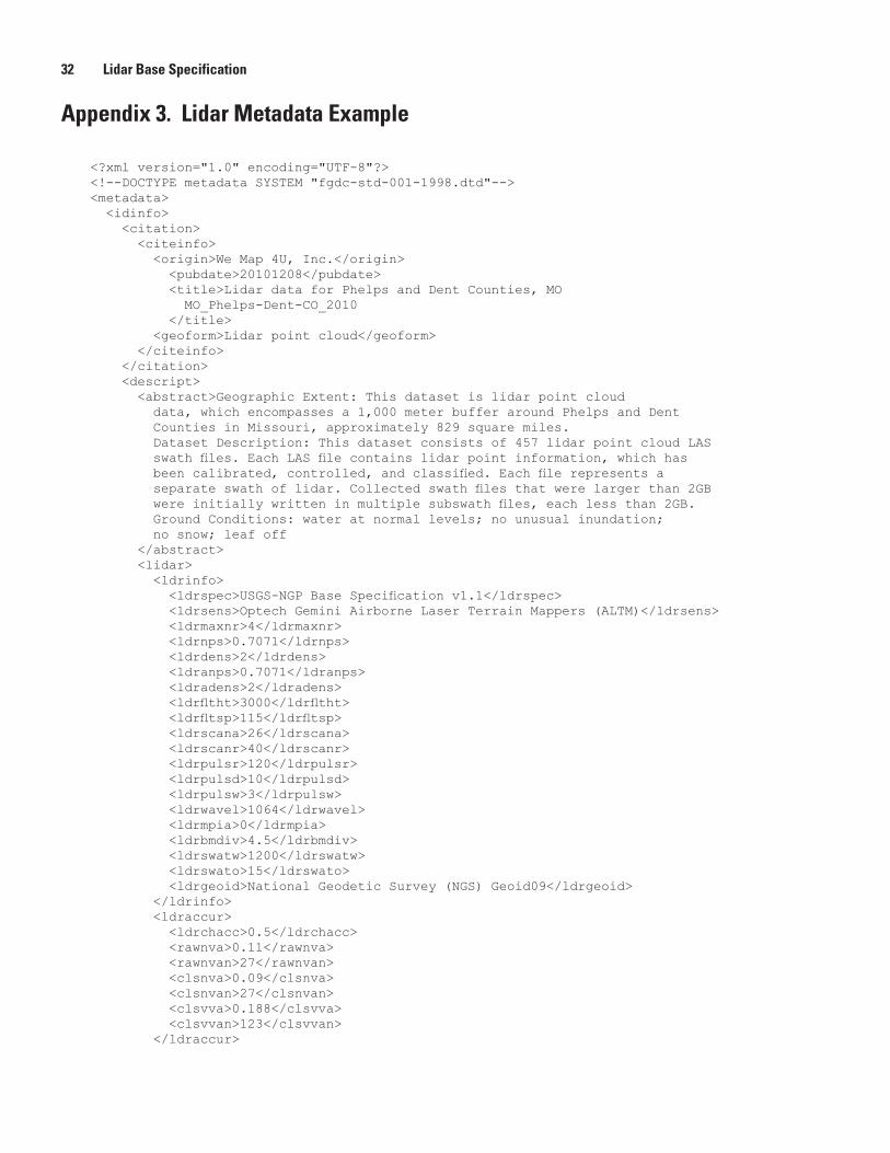
32 Lidar Base Specification
Appendix 3. Lidar Metadata Example
<?xml version="1.0" encoding="UTF-8"?><!--DOCTYPE metadata SYSTEM "fgdc-std-001-1998.dtd"--><metadata> <idinfo> <citation> <citeinfo> <origin>We Map 4U, Inc.</origin> <pubdate>20101208</pubdate> <title>Lidar data for Phelps and Dent Counties, MO MO_Phelps-Dent-CO_2010 </title> <geoform>Lidar point cloud</geoform> </citeinfo> </citation> <descript> <abstract>Geographic Extent: This dataset is lidar point cloud data, which encompasses a 1,000 meter buffer around Phelps and Dent Counties in Missouri, approximately 829 square miles. Dataset Description: This dataset consists of 457 lidar point cloud LAS swath files. Each LAS file contains lidar point information, which has been calibrated, controlled, and classified. Each file represents a separate swath of lidar. Collected swath files that were larger than 2GB were initially written in multiple subswath files, each less than 2GB. Ground Conditions: water at normal levels; no unusual inundation; no snow; leaf off </abstract> <lidar> <ldrinfo> <ldrspec>USGS-NGP Base Specification v1.1</ldrspec> <ldrsens>Optech Gemini Airborne Laser Terrain Mappers (ALTM)</ldrsens> <ldrmaxnr>4</ldrmaxnr> <ldrnps>0.7071</ldrnps> <ldrdens>2</ldrdens> <ldranps>0.7071</ldranps> <ldradens>2</ldradens> <ldrfltht>3000</ldrfltht> <ldrfltsp>115</ldrfltsp> <ldrscana>26</ldrscana> <ldrscanr>40</ldrscanr> <ldrpulsr>120</ldrpulsr> <ldrpulsd>10</ldrpulsd> <ldrpulsw>3</ldrpulsw> <ldrwavel>1064</ldrwavel> <ldrmpia>0</ldrmpia> <ldrbmdiv>4.5</ldrbmdiv> <ldrswatw>1200</ldrswatw> <ldrswato>15</ldrswato> <ldrgeoid>National Geodetic Survey (NGS) Geoid09</ldrgeoid> </ldrinfo> <ldraccur> <ldrchacc>0.5</ldrchacc> <rawnva>0.11</rawnva> <rawnvan>27</rawnvan> <clsnva>0.09</clsnva> <clsnvan>27</clsnvan> <clsvva>0.188</clsvva> <clsvvan>123</clsvvan> </ldraccur>
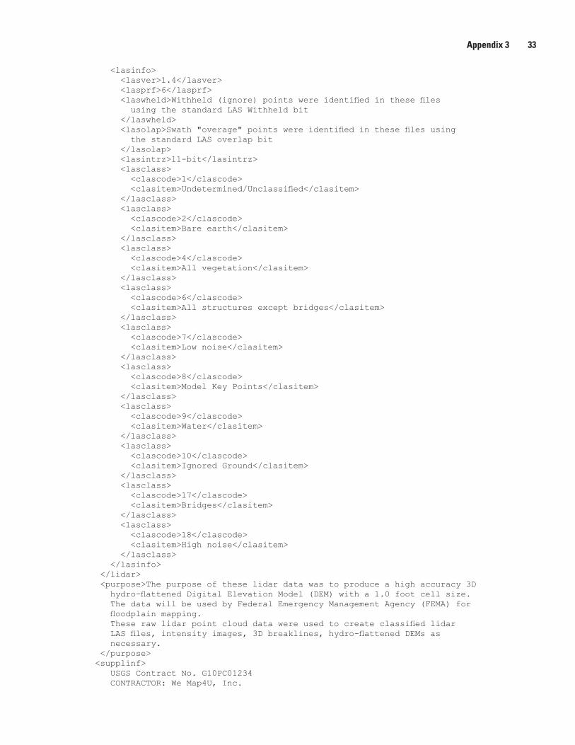
Appendix 3 33
<lasinfo> <lasver>1.4</lasver> <lasprf>6</lasprf> <laswheld>Withheld (ignore) points were identified in these files using the standard LAS Withheld bit </laswheld> <lasolap>Swath "overage" points were identified in these files using the standard LAS overlap bit </lasolap> <lasintrz>11-bit</lasintrz> <lasclass> <clascode>1</clascode> <clasitem>Undetermined/Unclassified</clasitem> </lasclass> <lasclass> <clascode>2</clascode> <clasitem>Bare earth</clasitem> </lasclass> <lasclass> <clascode>4</clascode> <clasitem>All vegetation</clasitem> </lasclass> <lasclass> <clascode>6</clascode> <clasitem>All structures except bridges</clasitem> </lasclass> <lasclass> <clascode>7</clascode> <clasitem>Low noise</clasitem> </lasclass> <lasclass> <clascode>8</clascode> <clasitem>Model Key Points</clasitem> </lasclass> <lasclass> <clascode>9</clascode> <clasitem>Water</clasitem> </lasclass> <lasclass> <clascode>10</clascode> <clasitem>Ignored Ground</clasitem> </lasclass> <lasclass> <clascode>17</clascode> <clasitem>Bridges</clasitem> </lasclass> <lasclass> <clascode>18</clascode> <clasitem>High noise</clasitem> </lasclass> </lasinfo> </lidar> <purpose>The purpose of these lidar data was to produce a high accuracy 3D hydro-flattened Digital Elevation Model (DEM) with a 1.0 foot cell size. The data will be used by Federal Emergency Management Agency (FEMA) for floodplain mapping. These raw lidar point cloud data were used to create classified lidar LAS files, intensity images, 3D breaklines, hydro-flattened DEMs as necessary. </purpose> <supplinf> USGS Contract No. G10PC01234 CONTRACTOR: We Map4U, Inc.
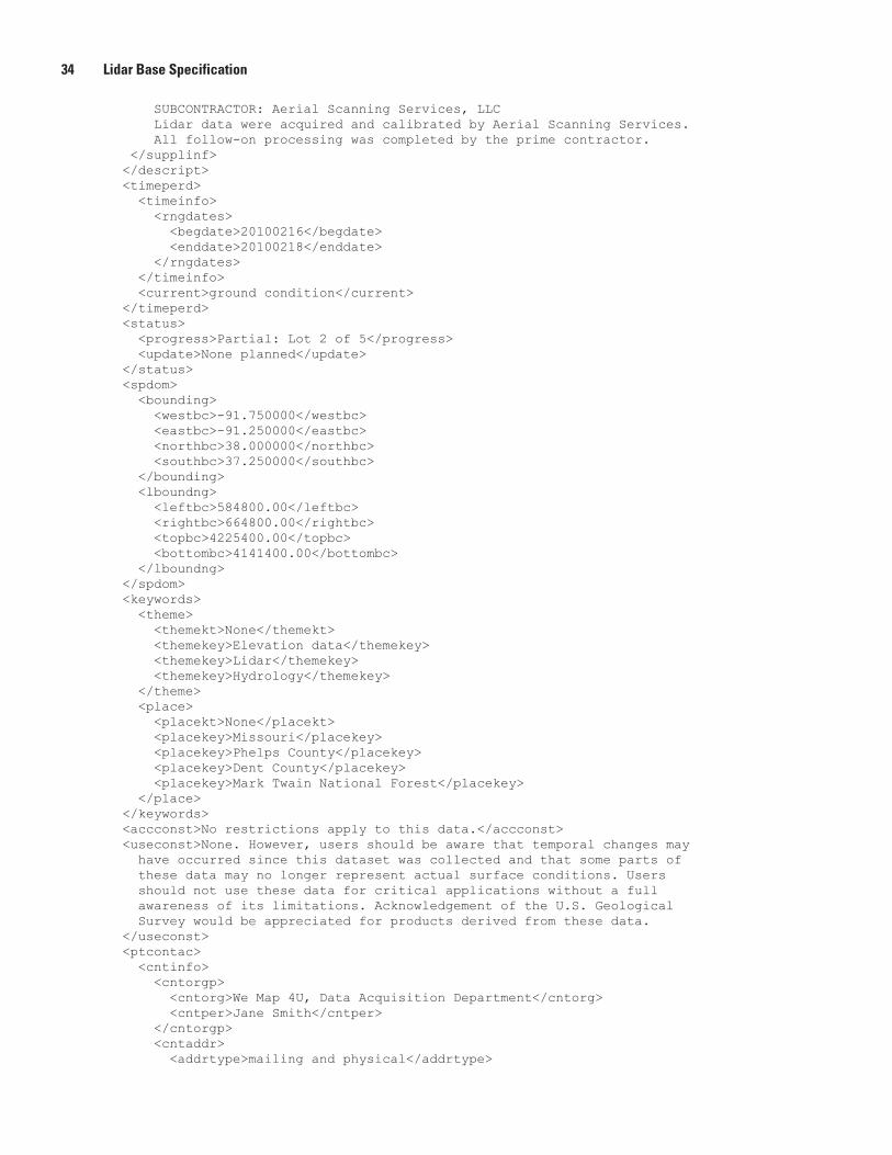
34 Lidar Base Specification
SUBCONTRACTOR: Aerial Scanning Services, LLC Lidar data were acquired and calibrated by Aerial Scanning Services. All follow-on processing was completed by the prime contractor. </supplinf> </descript> <timeperd> <timeinfo> <rngdates> <begdate>20100216</begdate> <enddate>20100218</enddate> </rngdates> </timeinfo> <current>ground condition</current> </timeperd> <status> <progress>Partial: Lot 2 of 5</progress> <update>None planned</update> </status> <spdom> <bounding> <westbc>-91.750000</westbc> <eastbc>-91.250000</eastbc> <northbc>38.000000</northbc> <southbc>37.250000</southbc> </bounding> <lboundng> <leftbc>584800.00</leftbc> <rightbc>664800.00</rightbc> <topbc>4225400.00</topbc> <bottombc>4141400.00</bottombc> </lboundng> </spdom> <keywords> <theme> <themekt>None</themekt> <themekey>Elevation data</themekey> <themekey>Lidar</themekey> <themekey>Hydrology</themekey> </theme> <place> <placekt>None</placekt> <placekey>Missouri</placekey> <placekey>Phelps County</placekey> <placekey>Dent County</placekey> <placekey>Mark Twain National Forest</placekey> </place> </keywords> <accconst>No restrictions apply to this data.</accconst> <useconst>None. However, users should be aware that temporal changes may have occurred since this dataset was collected and that some parts of these data may no longer represent actual surface conditions. Users should not use these data for critical applications without a full awareness of its limitations. Acknowledgement of the U.S. Geological Survey would be appreciated for products derived from these data. </useconst> <ptcontac> <cntinfo> <cntorgp> <cntorg>We Map 4U, Data Acquisition Department</cntorg> <cntper>Jane Smith</cntper> </cntorgp> <cntaddr> <addrtype>mailing and physical</addrtype>
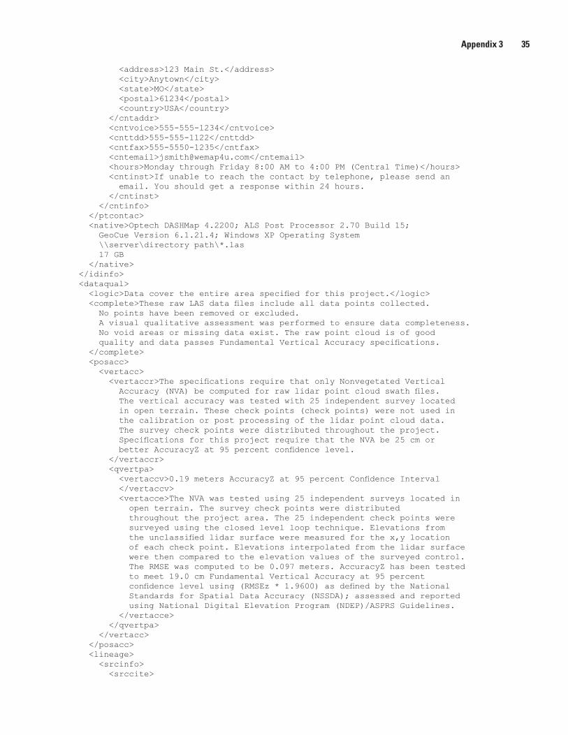
Appendix 3 35
<address>123 Main St.</address> <city>Anytown</city> <state>MO</state> <postal>61234</postal> <country>USA</country> </cntaddr> <cntvoice>555-555-1234</cntvoice> <cnttdd>555-555-1122</cnttdd> <cntfax>555-5550-1235</cntfax> <cntemail>[email protected]</cntemail> <hours>Monday through Friday 8:00 AM to 4:00 PM (Central Time)</hours> <cntinst>If unable to reach the contact by telephone, please send an email. You should get a response within 24 hours. </cntinst> </cntinfo> </ptcontac> <native>Optech DASHMap 4.2200; ALS Post Processor 2.70 Build 15; GeoCue Version 6.1.21.4; Windows XP Operating System \\server\directory path\*.las 17 GB </native> </idinfo> <dataqual> <logic>Data cover the entire area specified for this project.</logic> <complete>These raw LAS data files include all data points collected. No points have been removed or excluded. A visual qualitative assessment was performed to ensure data completeness. No void areas or missing data exist. The raw point cloud is of good quality and data passes Fundamental Vertical Accuracy specifications. </complete> <posacc> <vertacc> <vertaccr>The specifications require that only Nonvegetated Vertical Accuracy (NVA) be computed for raw lidar point cloud swath files. The vertical accuracy was tested with 25 independent survey located in open terrain. These check points (check points) were not used in the calibration or post processing of the lidar point cloud data. The survey check points were distributed throughout the project. Specifications for this project require that the NVA be 25 cm or better AccuracyZ at 95 percent confidence level. </vertaccr> <qvertpa> <vertaccv>0.19 meters AccuracyZ at 95 percent Confidence Interval </vertaccv> <vertacce>The NVA was tested using 25 independent surveys located in open terrain. The survey check points were distributed throughout the project area. The 25 independent check points were surveyed using the closed level loop technique. Elevations from the unclassified lidar surface were measured for the x,y location of each check point. Elevations interpolated from the lidar surface were then compared to the elevation values of the surveyed control. The RMSE was computed to be 0.097 meters. AccuracyZ has been tested to meet 19.0 cm Fundamental Vertical Accuracy at 95 percent confidence level using (RMSEz * 1.9600) as defined by the National Standards for Spatial Data Accuracy (NSSDA); assessed and reported using National Digital Elevation Program (NDEP)/ASPRS Guidelines. </vertacce> </qvertpa> </vertacc> </posacc> <lineage> <srcinfo> <srccite>
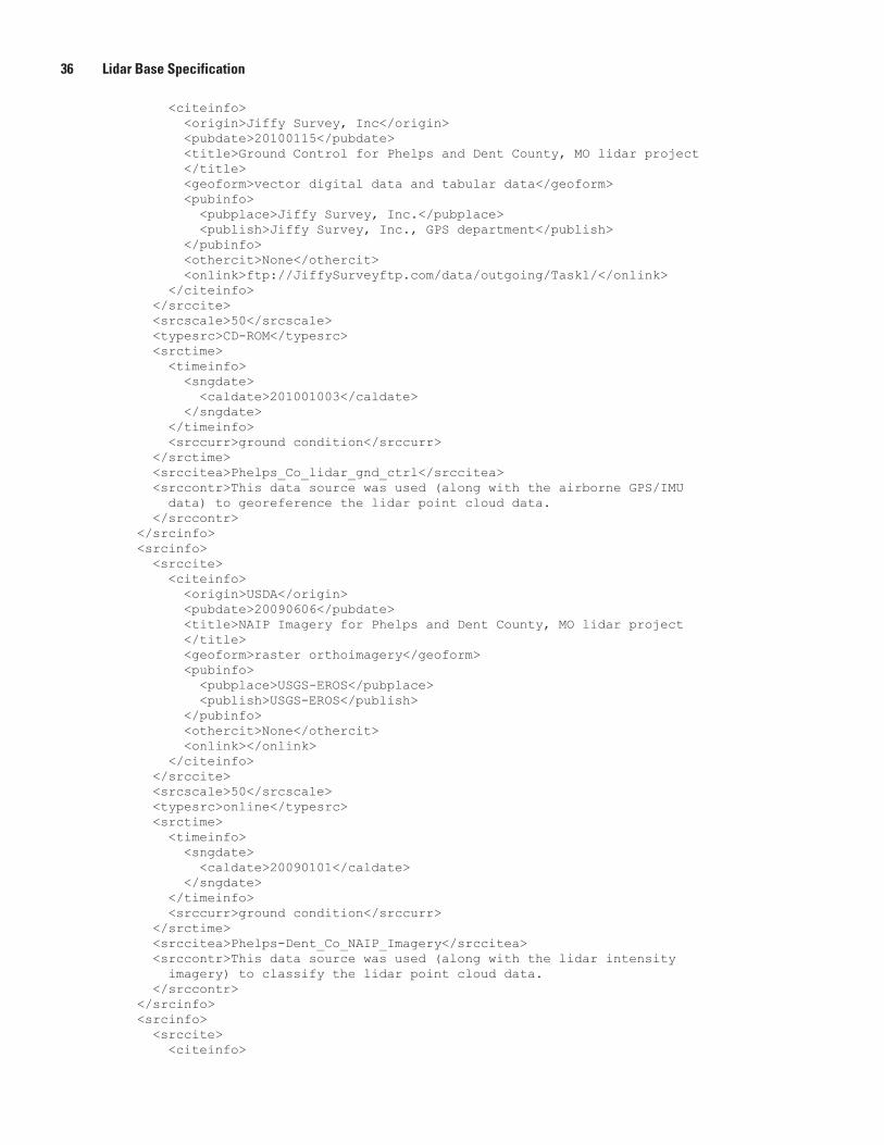
36 Lidar Base Specification
<citeinfo> <origin>Jiffy Survey, Inc</origin> <pubdate>20100115</pubdate> <title>Ground Control for Phelps and Dent County, MO lidar project </title> <geoform>vector digital data and tabular data</geoform> <pubinfo> <pubplace>Jiffy Survey, Inc.</pubplace> <publish>Jiffy Survey, Inc., GPS department</publish> </pubinfo> <othercit>None</othercit> <onlink>ftp://JiffySurveyftp.com/data/outgoing/Task1/</onlink> </citeinfo> </srccite> <srcscale>50</srcscale> <typesrc>CD-ROM</typesrc> <srctime> <timeinfo> <sngdate> <caldate>201001003</caldate> </sngdate> </timeinfo> <srccurr>ground condition</srccurr> </srctime> <srccitea>Phelps_Co_lidar_gnd_ctrl</srccitea> <srccontr>This data source was used (along with the airborne GPS/IMU data) to georeference the lidar point cloud data. </srccontr> </srcinfo> <srcinfo> <srccite> <citeinfo> <origin>USDA</origin> <pubdate>20090606</pubdate> <title>NAIP Imagery for Phelps and Dent County, MO lidar project </title> <geoform>raster orthoimagery</geoform> <pubinfo> <pubplace>USGS-EROS</pubplace> <publish>USGS-EROS</publish> </pubinfo> <othercit>None</othercit> <onlink></onlink> </citeinfo> </srccite> <srcscale>50</srcscale> <typesrc>online</typesrc> <srctime> <timeinfo> <sngdate> <caldate>20090101</caldate> </sngdate> </timeinfo> <srccurr>ground condition</srccurr> </srctime> <srccitea>Phelps-Dent_Co_NAIP_Imagery</srccitea> <srccontr>This data source was used (along with the lidar intensity imagery) to classify the lidar point cloud data. </srccontr> </srcinfo> <srcinfo> <srccite> <citeinfo>
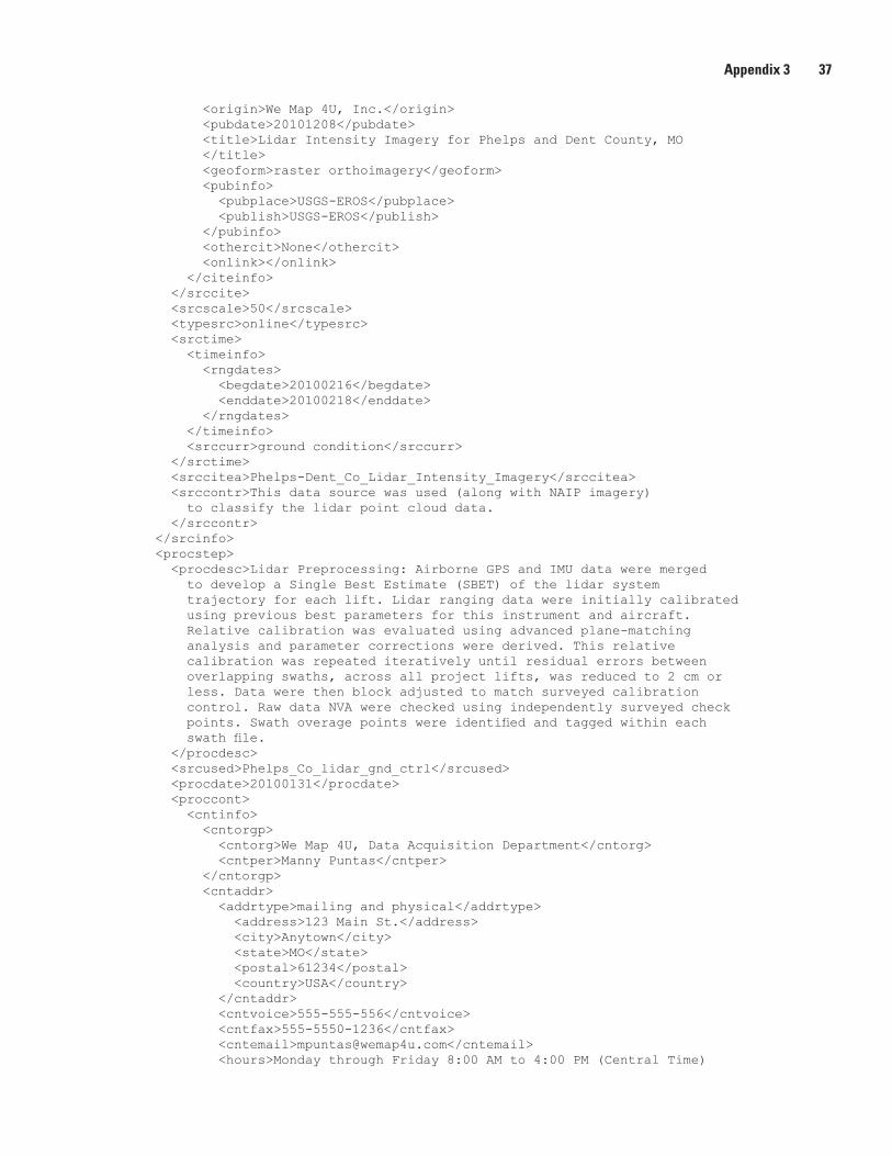
Appendix 3 37
<origin>We Map 4U, Inc.</origin> <pubdate>20101208</pubdate> <title>Lidar Intensity Imagery for Phelps and Dent County, MO </title> <geoform>raster orthoimagery</geoform> <pubinfo> <pubplace>USGS-EROS</pubplace> <publish>USGS-EROS</publish> </pubinfo> <othercit>None</othercit> <onlink></onlink> </citeinfo> </srccite> <srcscale>50</srcscale> <typesrc>online</typesrc> <srctime> <timeinfo> <rngdates> <begdate>20100216</begdate> <enddate>20100218</enddate> </rngdates> </timeinfo> <srccurr>ground condition</srccurr> </srctime> <srccitea>Phelps-Dent_Co_Lidar_Intensity_Imagery</srccitea> <srccontr>This data source was used (along with NAIP imagery) to classify the lidar point cloud data. </srccontr> </srcinfo> <procstep> <procdesc>Lidar Preprocessing: Airborne GPS and IMU data were merged to develop a Single Best Estimate (SBET) of the lidar system trajectory for each lift. Lidar ranging data were initially calibrated using previous best parameters for this instrument and aircraft. Relative calibration was evaluated using advanced plane-matching analysis and parameter corrections were derived. This relative calibration was repeated iteratively until residual errors between overlapping swaths, across all project lifts, was reduced to 2 cm or less. Data were then block adjusted to match surveyed calibration control. Raw data NVA were checked using independently surveyed check points. Swath overage points were identified and tagged within each swath file. </procdesc> <srcused>Phelps_Co_lidar_gnd_ctrl</srcused> <procdate>20100131</procdate> <proccont> <cntinfo> <cntorgp> <cntorg>We Map 4U, Data Acquisition Department</cntorg> <cntper>Manny Puntas</cntper> </cntorgp> <cntaddr> <addrtype>mailing and physical</addrtype> <address>123 Main St.</address> <city>Anytown</city> <state>MO</state> <postal>61234</postal> <country>USA</country> </cntaddr> <cntvoice>555-555-556</cntvoice> <cntfax>555-5550-1236</cntfax> <cntemail>[email protected]</cntemail> <hours>Monday through Friday 8:00 AM to 4:00 PM (Central Time)
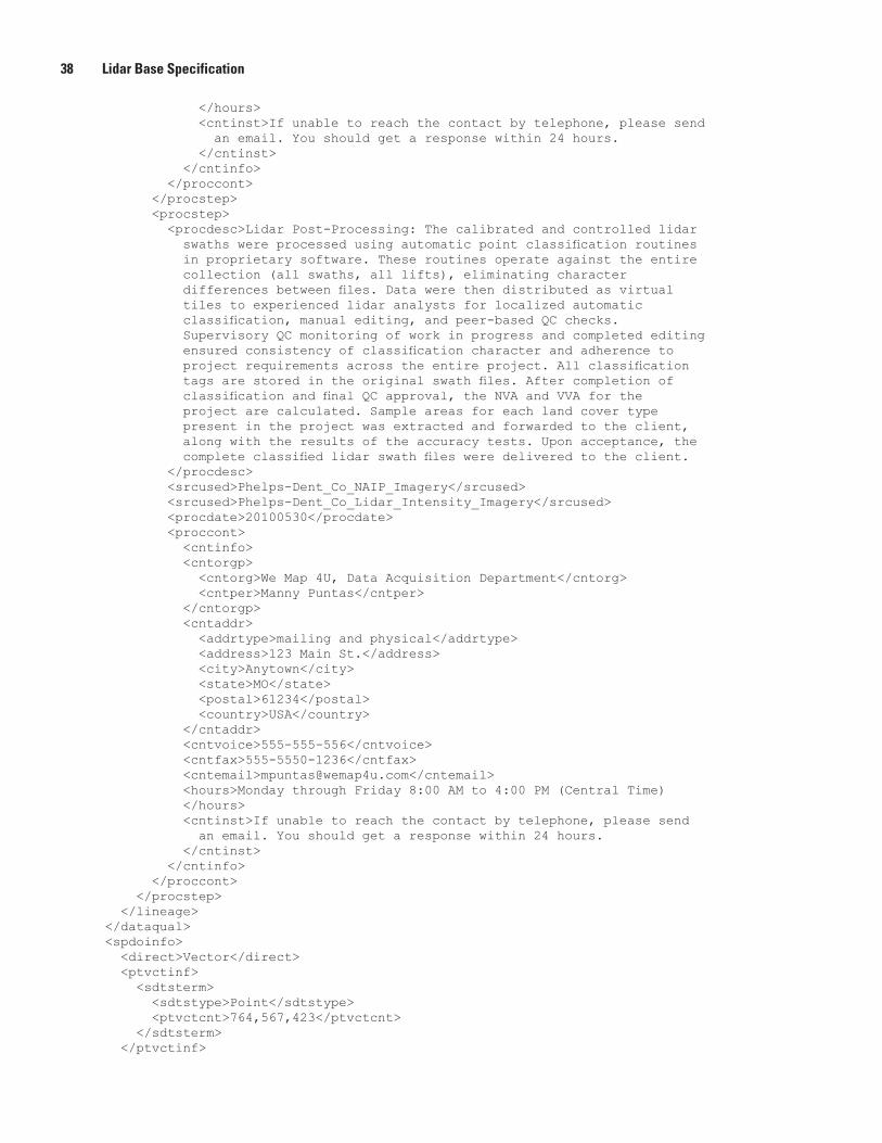
38 Lidar Base Specification
</hours> <cntinst>If unable to reach the contact by telephone, please send an email. You should get a response within 24 hours. </cntinst> </cntinfo> </proccont> </procstep> <procstep> <procdesc>Lidar Post-Processing: The calibrated and controlled lidar swaths were processed using automatic point classification routines in proprietary software. These routines operate against the entire collection (all swaths, all lifts), eliminating character differences between files. Data were then distributed as virtual tiles to experienced lidar analysts for localized automatic classification, manual editing, and peer-based QC checks. Supervisory QC monitoring of work in progress and completed editing ensured consistency of classification character and adherence to project requirements across the entire project. All classification tags are stored in the original swath files. After completion of classification and final QC approval, the NVA and VVA for the project are calculated. Sample areas for each land cover type present in the project was extracted and forwarded to the client, along with the results of the accuracy tests. Upon acceptance, the complete classified lidar swath files were delivered to the client. </procdesc> <srcused>Phelps-Dent_Co_NAIP_Imagery</srcused> <srcused>Phelps-Dent_Co_Lidar_Intensity_Imagery</srcused> <procdate>20100530</procdate> <proccont> <cntinfo> <cntorgp> <cntorg>We Map 4U, Data Acquisition Department</cntorg> <cntper>Manny Puntas</cntper> </cntorgp> <cntaddr> <addrtype>mailing and physical</addrtype> <address>123 Main St.</address> <city>Anytown</city> <state>MO</state> <postal>61234</postal> <country>USA</country> </cntaddr> <cntvoice>555-555-556</cntvoice> <cntfax>555-5550-1236</cntfax> <cntemail>[email protected]</cntemail> <hours>Monday through Friday 8:00 AM to 4:00 PM (Central Time) </hours> <cntinst>If unable to reach the contact by telephone, please send an email. You should get a response within 24 hours. </cntinst> </cntinfo> </proccont> </procstep> </lineage> </dataqual> <spdoinfo> <direct>Vector</direct> <ptvctinf> <sdtsterm> <sdtstype>Point</sdtstype> <ptvctcnt>764,567,423</ptvctcnt> </sdtsterm> </ptvctinf>
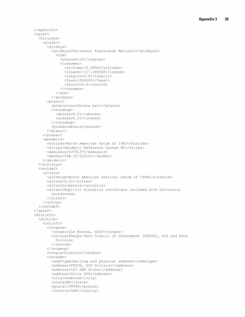
Appendix 3 39
</spdoinfo> <spref> <horizsys> <planar> <gridsys> <gridsysn>Universal Transverse Mercator</gridsysn> <utm> <utmzone>15</utmzone> <transmer> <sfctrmer>0.9996</sfctrmer> <longcm>-117.000000</longcm> <latprjo>0.0</latprjo> <feast>500000</feast> <fnorth>0.0</fnorth> </transmer> </utm> </gridsys> <planci> <plance>coordinate pair</plance> <coordrep> <absres>0.01</absres> <ordres>0.01</ordres> </coordrep> <plandu>meters</plandu> </planci> </planar> <geodetic> <horizdn>North American Datum of 1983</horizdn> <ellips>Geodetic Reference System 80</ellips> <semiaxis>6378137</semiaxis> <denflat>298.257222101</denflat> </geodetic> </horizsys> <vertdef> <altsys> <altdatum>North American Vertical Datum of 1988</altdatum> <altres>0.01</altres> <altunits>meters</altunits> <altenc>Explicit elevation coordinate included with horizontal coordinates </altenc> </altsys> </vertdef> </spref> <distinfo> <distrib> <cntinfo> <cntperp> <cntper>Jim Brooks, GISP</cntper> <cntorg>Phelps-Dent Council of Government (PDCOG), GIS and Data Division </cntorg> </cntperp> <cntpos>Director</cntpos> <cntaddr> <addrtype>mailing and physical address</addrtype> <address>PDCOG, GIS Division</address> <address>123 ABD Street</address> <address>Suite 456</address> <city>Sometown</city> <state>MO</state> <postal>99999</postal> <country>USA</country>
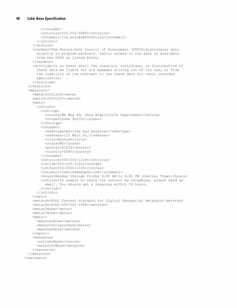
40 Lidar Base Specification
</cntaddr> <cntvoice>555-555-9999</cntvoice> <cntemail>[email protected]</cntemail> </cntinfo> </distrib> <resdesc>The Phelps-Dent Council of Government (PDCOG)distributes data directly to program partners. Public access to the data is available from the USGS as listed below. </resdesc> <distliab>In no event shall the creators, custodians, or distributors of these data be liable for any damages arising out of its use, or from the inability of the customer to use these data for their intended application. </distliab> </distinfo> <metainfo> <metd>20101206</metd> <metrd>20101207</metrd> <metc> <cntinfo> <cntorgp> <cntorg>We Map 4U, Data Acquisition Department</cntorg> <cntper>John Smith</cntper> </cntorgp> <cntaddr> <addrtype>mailing and physical</addrtype> <address>123 Main St.</address> <city>Anytown</city> <state>MO</state> <postal>61234</postal> <country>USA</country> </cntaddr> <cntvoice>555-555-1234</cntvoice> <cnttdd>555-555-1122</cnttdd> <cntfax>555-5550-1235</cntfax> <cntemail>[email protected]</cntemail> <hours>Monday through Friday 8:00 AM to 4:00 PM (Central Time)</hours> <cntinst>If unable to reach the contact by telephone, please send an email. You should get a response within 24 hours. </cntinst> </cntinfo> </metc> <metstdn>FGDC Content Standard for Digital Geospatial Metadata</metstdn> <metstdv>FGDC-STD-001-1998</metstdv> <metac>None</metac> <metuc>None</metuc> <metsi> <metscs>None</metscs> <metsc>Unclassified</metsc> <metshd>None</metshd> </metsi> <metextns> <onlink>None</onlink> <metprof>None</metprof> </metextns> </metainfo></metadata>
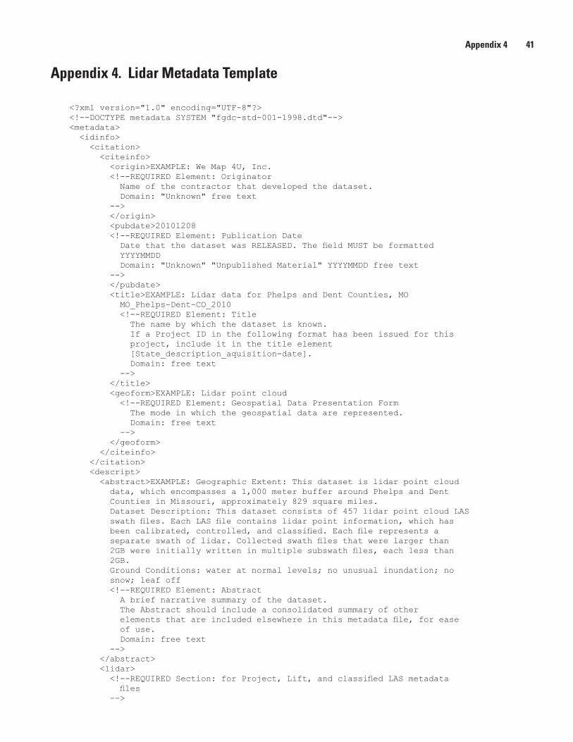
Appendix 4 41
Appendix 4. Lidar Metadata Template
<?xml version="1.0" encoding="UTF-8"?><!--DOCTYPE metadata SYSTEM "fgdc-std-001-1998.dtd"--><metadata> <idinfo> <citation> <citeinfo> <origin>EXAMPLE: We Map 4U, Inc. <!--REQUIRED Element: Originator Name of the contractor that developed the dataset. Domain: "Unknown" free text --> </origin> <pubdate>20101208 <!--REQUIRED Element: Publication Date Date that the dataset was RELEASED. The field MUST be formatted YYYYMMDD Domain: "Unknown" "Unpublished Material" YYYYMMDD free text --> </pubdate> <title>EXAMPLE: Lidar data for Phelps and Dent Counties, MO MO_Phelps-Dent-CO_2010 <!--REQUIRED Element: Title The name by which the dataset is known. If a Project ID in the following format has been issued for this project, include it in the title element [State_description_aquisition-date]. Domain: free text --> </title> <geoform>EXAMPLE: Lidar point cloud <!--REQUIRED Element: Geospatial Data Presentation Form The mode in which the geospatial data are represented. Domain: free text --> </geoform> </citeinfo> </citation> <descript> <abstract>EXAMPLE: Geographic Extent: This dataset is lidar point cloud data, which encompasses a 1,000 meter buffer around Phelps and Dent Counties in Missouri, approximately 829 square miles. Dataset Description: This dataset consists of 457 lidar point cloud LAS swath files. Each LAS file contains lidar point information, which has been calibrated, controlled, and classified. Each file represents a separate swath of lidar. Collected swath files that were larger than 2GB were initially written in multiple subswath files, each less than 2GB. Ground Conditions: water at normal levels; no unusual inundation; no snow; leaf off <!--REQUIRED Element: Abstract A brief narrative summary of the dataset. The Abstract should include a consolidated summary of other elements that are included elsewhere in this metadata file, for ease of use. Domain: free text --> </abstract> <lidar> <!--REQUIRED Section: for Project, Lift, and classified LAS metadata files -->
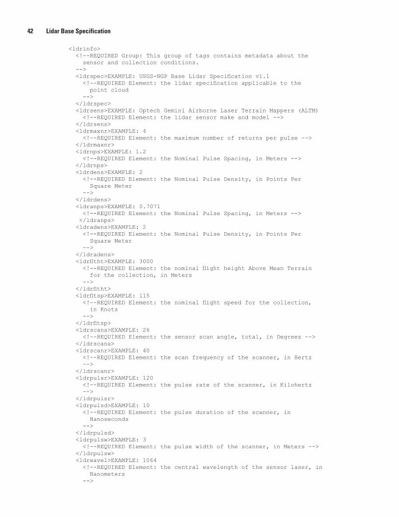
42 Lidar Base Specification
<ldrinfo> <!--REQUIRED Group: This group of tags contains metadata about the sensor and collection conditions. --> <ldrspec>EXAMPLE: USGS-NGP Base Lidar Specification v1.1 <!--REQUIRED Element: the lidar specification applicable to the point cloud --> </ldrspec> <ldrsens>EXAMPLE: Optech Gemini Airborne Laser Terrain Mappers (ALTM) <!--REQUIRED Element: the lidar sensor make and model --> </ldrsens> <ldrmaxnr>EXAMPLE: 4 <!--REQUIRED Element: the maximum number of returns per pulse --> </ldrmaxnr> <ldrnps>EXAMPLE: 1.2 <!--REQUIRED Element: the Nominal Pulse Spacing, in Meters --> </ldrnps> <ldrdens>EXAMPLE: 2 <!--REQUIRED Element: the Nominal Pulse Density, in Points Per Square Meter --> </ldrdens> <ldranps>EXAMPLE: 0.7071 <!--REQUIRED Element: the Nominal Pulse Spacing, in Meters --> </ldranps> <ldradens>EXAMPLE: 2 <!--REQUIRED Element: the Nominal Pulse Density, in Points Per Square Meter --> </ldradens> <ldrfltht>EXAMPLE: 3000 <!--REQUIRED Element: the nominal flight height Above Mean Terrain for the collection, in Meters --> </ldrfltht> <ldrfltsp>EXAMPLE: 115 <!--REQUIRED Element: the nominal flight speed for the collection, in Knots --> </ldrfltsp> <ldrscana>EXAMPLE: 26 <!--REQUIRED Element: the sensor scan angle, total, in Degrees --> </ldrscana> <ldrscanr>EXAMPLE: 40 <!--REQUIRED Element: the scan frequency of the scanner, in Hertz --> </ldrscanr> <ldrpulsr>EXAMPLE: 120 <!--REQUIRED Element: the pulse rate of the scanner, in Kilohertz --> </ldrpulsr> <ldrpulsd>EXAMPLE: 10 <!--REQUIRED Element: the pulse duration of the scanner, in Nanoseconds --> </ldrpulsd> <ldrpulsw>EXAMPLE: 3 <!--REQUIRED Element: the pulse width of the scanner, in Meters --> </ldrpulsw> <ldrwavel>EXAMPLE: 1064 <!--REQUIRED Element: the central wavelength of the sensor laser, in Nanometers -->
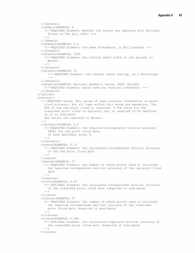
Appendix 4 43
</ldrwavel> <ldrmpia>EXAMPLE: 0 <!--REQUIRED Element: Whether the sensor was operated with Multiple Pulses In The Air, 0=No; 1=Y --> </ldrmpia> <ldrbmdiv>EXAMPLE: 0.3 <!--REQUIRED Element: the beam divergence, in Milliradians --> </ldrbmdiv> <ldrswatw>EXAMPLE: 1200 <!--REQUIRED Element: the nominal swath width on the ground, in Meters --> </ldrswatw> <ldrswato>EXAMPLE: 15 <!--REQUIRED Element: the nominal swath overlap, as a Percentage --> </ldrswato> <ldrgeoid>EXAMPLE: National Geodetic Survey (NGS) Geoid09 <!--REQUIRED Element: Geoid used for vertical reference. --> </ldrgeoid> </ldrinfo> <ldraccur> <!--REQUIRED Group: This group of tags contains information on point cloud accuracy. Not all tags within this group are mandatory. The NVA of the raw point cloud is required. A VVA value for the classified point cloud is optional, but is required to be reported if it is available. ALL Values are reported in Meters. --> <ldrchacc>EXAMPLE: 0.5 <!--REQUIRED Element: the required nonvegetated vertical accuracy (NVA) for the point cloud data. If none specified, enter 0. --> </ldrchacc> <rawnva>EXAMPLE: 0.11 <!--REQUIRED Element: the calculated nonvegetated vertical accuracy of the raw point cloud data --> </rawnva> <rawnvan>EXAMPLE: 27 <!--REQUIRED Element: the number of check points used to calculate the reported nonvegetated vertical accuracy of the raw point cloud data --> </rawnvan> <clsnva>EXAMPLE: 0.09 <!--OPTIONAL Element: the calculated nonvegetated vertical accuracy of the classified point cloud data (required if available) --> </clsnva> <clsnvan>EXAMPLE: 27 <!--REQUIRED Element: the number of check points used to calculate the reported nonvegetated vertical accuracy of the classified point cloud data (required if available) --> </clsnvan> <clsvva>EXAMPLE: 0.188 <!--OPTIONAL Element: the calculated vegetated vertical accuracy of the classified point cloud data (required if available) --> </clsvva>
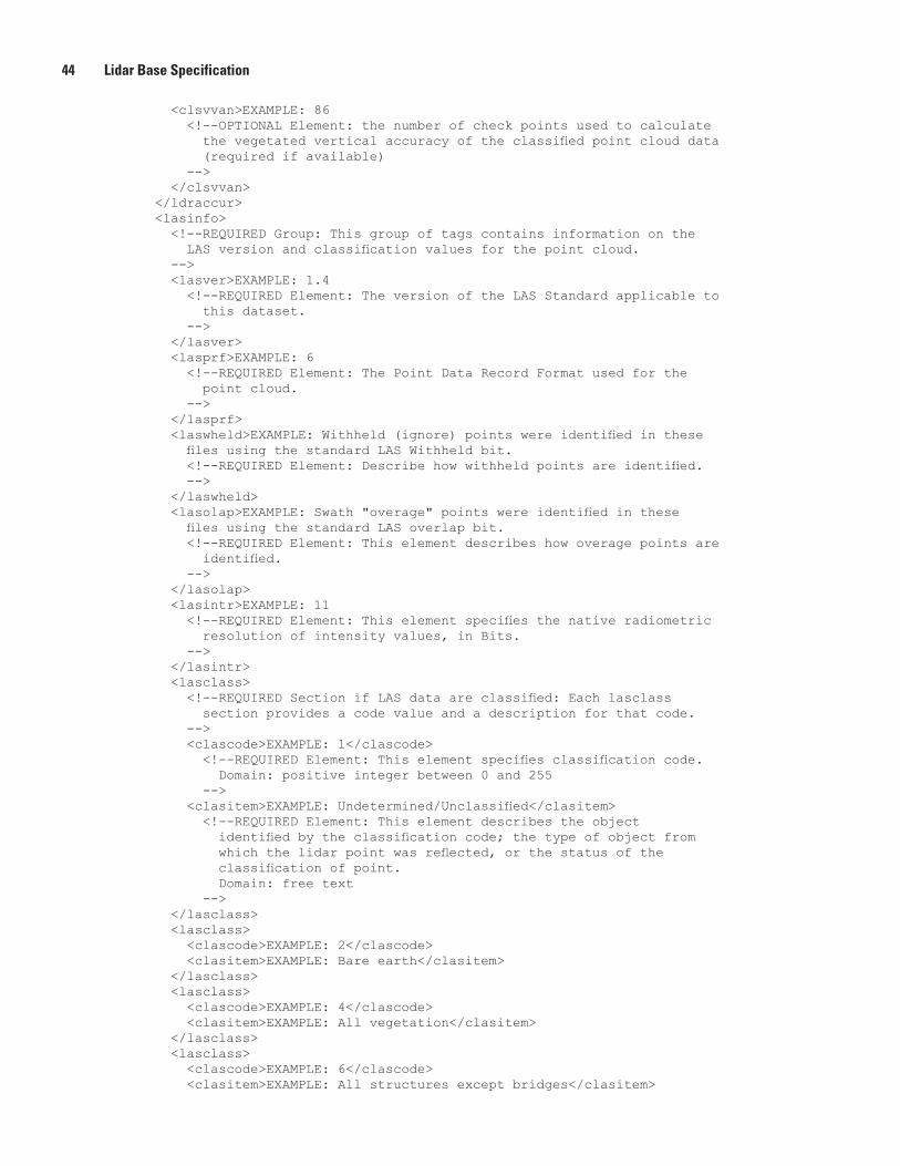
44 Lidar Base Specification
<clsvvan>EXAMPLE: 86 <!--OPTIONAL Element: the number of check points used to calculate the vegetated vertical accuracy of the classified point cloud data (required if available) --> </clsvvan> </ldraccur> <lasinfo> <!--REQUIRED Group: This group of tags contains information on the LAS version and classification values for the point cloud. --> <lasver>EXAMPLE: 1.4 <!--REQUIRED Element: The version of the LAS Standard applicable to this dataset. --> </lasver> <lasprf>EXAMPLE: 6 <!--REQUIRED Element: The Point Data Record Format used for the point cloud. --> </lasprf> <laswheld>EXAMPLE: Withheld (ignore) points were identified in these files using the standard LAS Withheld bit. <!--REQUIRED Element: Describe how withheld points are identified. --> </laswheld> <lasolap>EXAMPLE: Swath "overage" points were identified in these files using the standard LAS overlap bit. <!--REQUIRED Element: This element describes how overage points are identified. --> </lasolap> <lasintr>EXAMPLE: 11 <!--REQUIRED Element: This element specifies the native radiometric resolution of intensity values, in Bits. --> </lasintr> <lasclass> <!--REQUIRED Section if LAS data are classified: Each lasclass section provides a code value and a description for that code. --> <clascode>EXAMPLE: 1</clascode> <!--REQUIRED Element: This element specifies classification code. Domain: positive integer between 0 and 255 --> <clasitem>EXAMPLE: Undetermined/Unclassified</clasitem> <!--REQUIRED Element: This element describes the object identified by the classification code; the type of object from which the lidar point was reflected, or the status of the classification of point. Domain: free text --> </lasclass> <lasclass> <clascode>EXAMPLE: 2</clascode> <clasitem>EXAMPLE: Bare earth</clasitem> </lasclass> <lasclass> <clascode>EXAMPLE: 4</clascode> <clasitem>EXAMPLE: All vegetation</clasitem> </lasclass> <lasclass> <clascode>EXAMPLE: 6</clascode> <clasitem>EXAMPLE: All structures except bridges</clasitem>
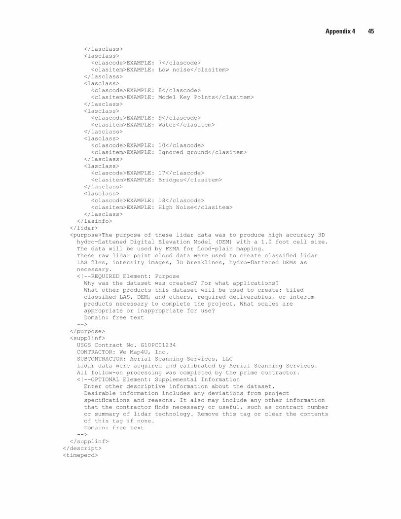
Appendix 4 45
</lasclass> <lasclass> <clascode>EXAMPLE: 7</clascode> <clasitem>EXAMPLE: Low noise</clasitem> </lasclass> <lasclass> <clascode>EXAMPLE: 8</clascode> <clasitem>EXAMPLE: Model Key Points</clasitem> </lasclass> <lasclass> <clascode>EXAMPLE: 9</clascode> <clasitem>EXAMPLE: Water</clasitem> </lasclass> <lasclass> <clascode>EXAMPLE: 10</clascode> <clasitem>EXAMPLE: Ignored ground</clasitem> </lasclass> <lasclass> <clascode>EXAMPLE: 17</clascode> <clasitem>EXAMPLE: Bridges</clasitem> </lasclass> <lasclass> <clascode>EXAMPLE: 18</clascode> <clasitem>EXAMPLE: High Noise</clasitem> </lasclass> </lasinfo> </lidar> <purpose>The purpose of these lidar data was to produce high accuracy 3D hydro-flattened Digital Elevation Model (DEM) with a 1.0 foot cell size. The data will be used by FEMA for flood-plain mapping. These raw lidar point cloud data were used to create classified lidar LAS files, intensity images, 3D breaklines, hydro-flattened DEMs as necessary. <!--REQUIRED Element: Purpose Why was the dataset was created? For what applications? What other products this dataset will be used to create: tiled classified LAS, DEM, and others, required deliverables, or interim products necessary to complete the project. What scales are appropriate or inappropriate for use? Domain: free text --> </purpose> <supplinf> USGS Contract No. G10PC01234 CONTRACTOR: We Map4U, Inc. SUBCONTRACTOR: Aerial Scanning Services, LLC Lidar data were acquired and calibrated by Aerial Scanning Services. All follow-on processing was completed by the prime contractor. <!--OPTIONAL Element: Supplemental Information Enter other descriptive information about the dataset. Desirable information includes any deviations from project specifications and reasons. It also may include any other information that the contractor finds necessary or useful, such as contract number or summary of lidar technology. Remove this tag or clear the contents of this tag if none. Domain: free text --> </supplinf> </descript> <timeperd>
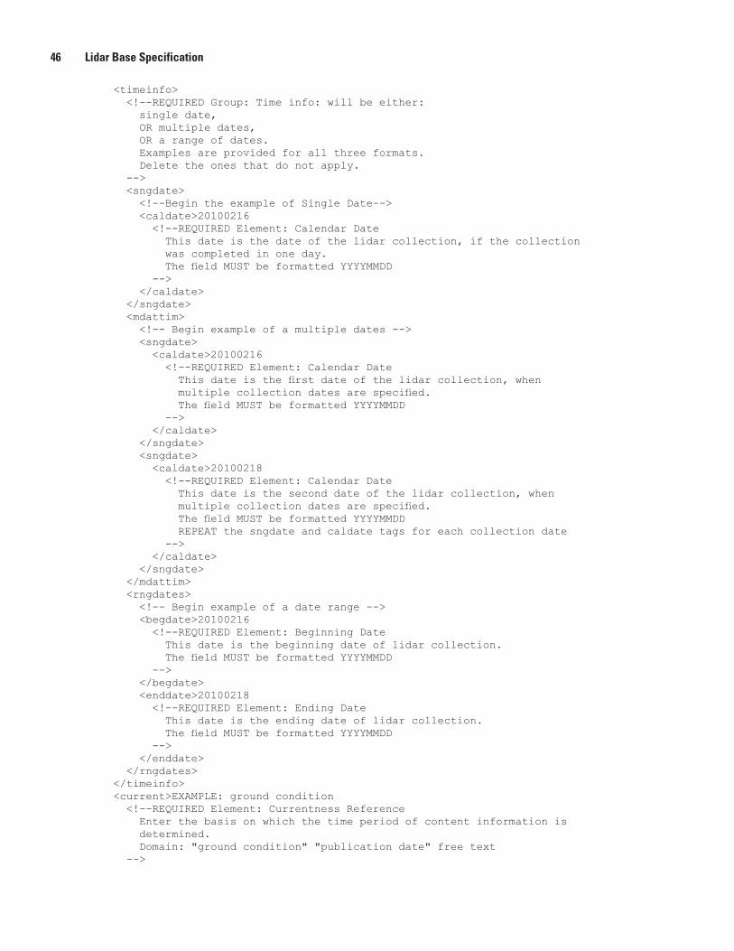
46 Lidar Base Specification
<timeinfo> <!--REQUIRED Group: Time info: will be either: single date, OR multiple dates, OR a range of dates. Examples are provided for all three formats. Delete the ones that do not apply. --> <sngdate> <!--Begin the example of Single Date--> <caldate>20100216 <!--REQUIRED Element: Calendar Date This date is the date of the lidar collection, if the collection was completed in one day. The field MUST be formatted YYYYMMDD --> </caldate> </sngdate> <mdattim> <!-- Begin example of a multiple dates --> <sngdate> <caldate>20100216 <!--REQUIRED Element: Calendar Date This date is the first date of the lidar collection, when multiple collection dates are specified. The field MUST be formatted YYYYMMDD --> </caldate> </sngdate> <sngdate> <caldate>20100218 <!--REQUIRED Element: Calendar Date This date is the second date of the lidar collection, when multiple collection dates are specified. The field MUST be formatted YYYYMMDD REPEAT the sngdate and caldate tags for each collection date --> </caldate> </sngdate> </mdattim> <rngdates> <!-- Begin example of a date range --> <begdate>20100216 <!--REQUIRED Element: Beginning Date This date is the beginning date of lidar collection. The field MUST be formatted YYYYMMDD --> </begdate> <enddate>20100218 <!--REQUIRED Element: Ending Date This date is the ending date of lidar collection. The field MUST be formatted YYYYMMDD --> </enddate> </rngdates> </timeinfo> <current>EXAMPLE: ground condition <!--REQUIRED Element: Currentness Reference Enter the basis on which the time period of content information is determined. Domain: "ground condition" "publication date" free text -->
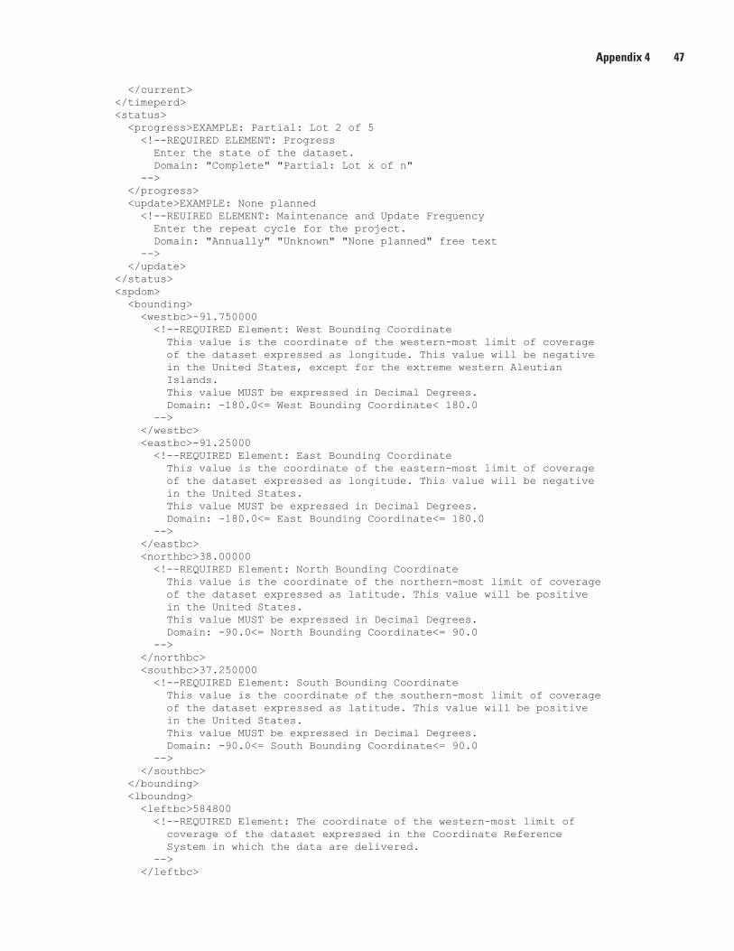
Appendix 4 47
</current> </timeperd> <status> <progress>EXAMPLE: Partial: Lot 2 of 5 <!--REQUIRED ELEMENT: Progress Enter the state of the dataset. Domain: "Complete" "Partial: Lot x of n" --> </progress> <update>EXAMPLE: None planned <!--REUIRED ELEMENT: Maintenance and Update Frequency Enter the repeat cycle for the project. Domain: "Annually" "Unknown" "None planned" free text --> </update> </status> <spdom> <bounding> <westbc>-91.750000 <!--REQUIRED Element: West Bounding Coordinate This value is the coordinate of the western-most limit of coverage of the dataset expressed as longitude. This value will be negative in the United States, except for the extreme western Aleutian Islands. This value MUST be expressed in Decimal Degrees. Domain: -180.0<= West Bounding Coordinate< 180.0 --> </westbc> <eastbc>-91.25000 <!--REQUIRED Element: East Bounding Coordinate This value is the coordinate of the eastern-most limit of coverage of the dataset expressed as longitude. This value will be negative in the United States. This value MUST be expressed in Decimal Degrees. Domain: -180.0<= East Bounding Coordinate<= 180.0 --> </eastbc> <northbc>38.00000 <!--REQUIRED Element: North Bounding Coordinate This value is the coordinate of the northern-most limit of coverage of the dataset expressed as latitude. This value will be positive in the United States. This value MUST be expressed in Decimal Degrees. Domain: -90.0<= North Bounding Coordinate<= 90.0 --> </northbc> <southbc>37.250000 <!--REQUIRED Element: South Bounding Coordinate This value is the coordinate of the southern-most limit of coverage of the dataset expressed as latitude. This value will be positive in the United States. This value MUST be expressed in Decimal Degrees. Domain: -90.0<= South Bounding Coordinate<= 90.0 --> </southbc> </bounding> <lboundng> <leftbc>584800 <!--REQUIRED Element: The coordinate of the western-most limit of coverage of the dataset expressed in the Coordinate Reference System in which the data are delivered. --> </leftbc>
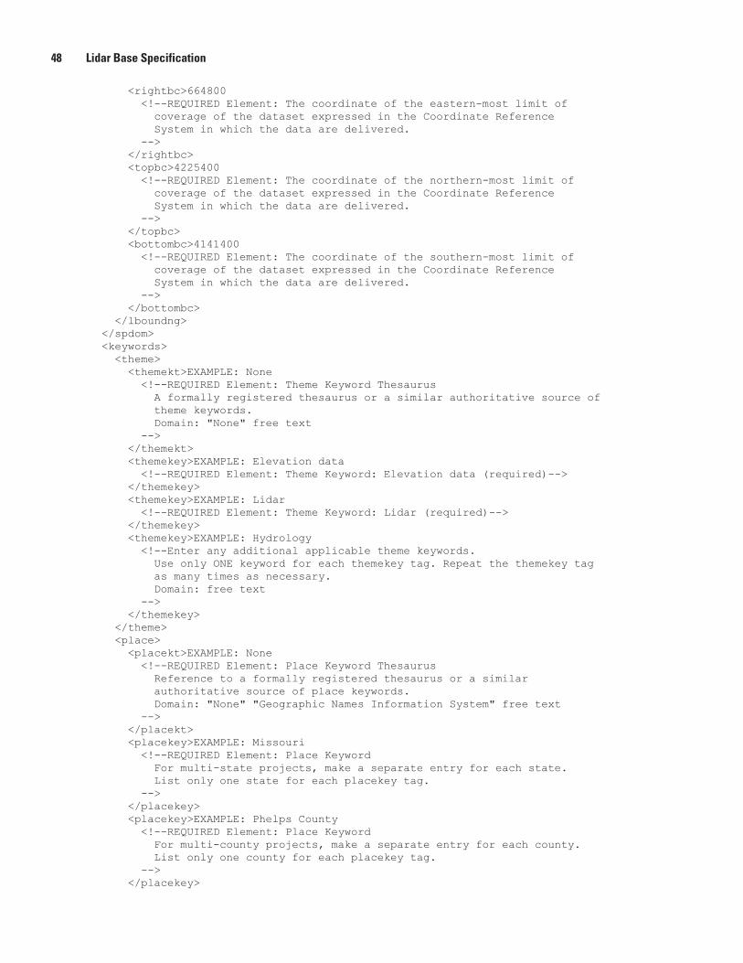
48 Lidar Base Specification
<rightbc>664800 <!--REQUIRED Element: The coordinate of the eastern-most limit of coverage of the dataset expressed in the Coordinate Reference System in which the data are delivered. --> </rightbc> <topbc>4225400 <!--REQUIRED Element: The coordinate of the northern-most limit of coverage of the dataset expressed in the Coordinate Reference System in which the data are delivered. --> </topbc> <bottombc>4141400 <!--REQUIRED Element: The coordinate of the southern-most limit of coverage of the dataset expressed in the Coordinate Reference System in which the data are delivered. --> </bottombc> </lboundng> </spdom> <keywords> <theme> <themekt>EXAMPLE: None <!--REQUIRED Element: Theme Keyword Thesaurus A formally registered thesaurus or a similar authoritative source of theme keywords. Domain: "None" free text --> </themekt> <themekey>EXAMPLE: Elevation data <!--REQUIRED Element: Theme Keyword: Elevation data (required)--> </themekey> <themekey>EXAMPLE: Lidar <!--REQUIRED Element: Theme Keyword: Lidar (required)--> </themekey> <themekey>EXAMPLE: Hydrology <!--Enter any additional applicable theme keywords. Use only ONE keyword for each themekey tag. Repeat the themekey tag as many times as necessary. Domain: free text --> </themekey> </theme> <place> <placekt>EXAMPLE: None <!--REQUIRED Element: Place Keyword Thesaurus Reference to a formally registered thesaurus or a similar authoritative source of place keywords. Domain: "None" "Geographic Names Information System" free text --> </placekt> <placekey>EXAMPLE: Missouri <!--REQUIRED Element: Place Keyword For multi-state projects, make a separate entry for each state. List only one state for each placekey tag. --> </placekey> <placekey>EXAMPLE: Phelps County <!--REQUIRED Element: Place Keyword For multi-county projects, make a separate entry for each county. List only one county for each placekey tag. --> </placekey>
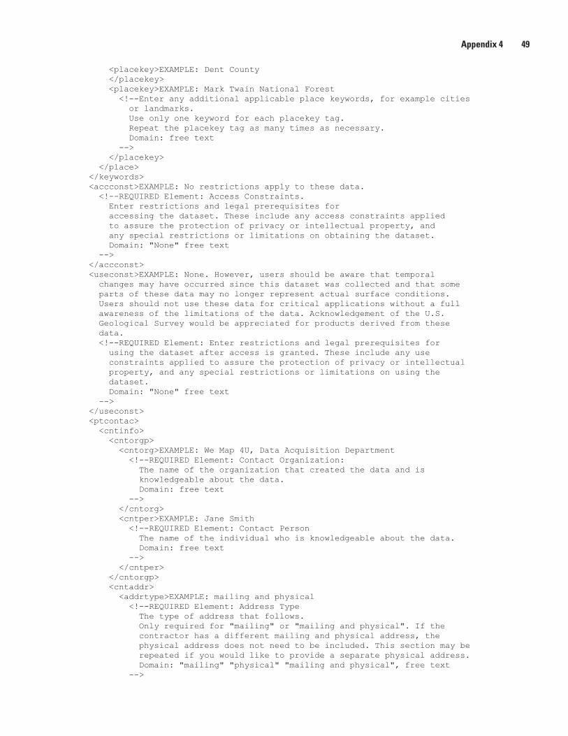
Appendix 4 49
<placekey>EXAMPLE: Dent County </placekey> <placekey>EXAMPLE: Mark Twain National Forest <!--Enter any additional applicable place keywords, for example cities or landmarks. Use only one keyword for each placekey tag. Repeat the placekey tag as many times as necessary. Domain: free text --> </placekey> </place> </keywords> <accconst>EXAMPLE: No restrictions apply to these data. <!--REQUIRED Element: Access Constraints. Enter restrictions and legal prerequisites for accessing the dataset. These include any access constraints applied to assure the protection of privacy or intellectual property, and any special restrictions or limitations on obtaining the dataset. Domain: "None" free text --> </accconst> <useconst>EXAMPLE: None. However, users should be aware that temporal changes may have occurred since this dataset was collected and that some parts of these data may no longer represent actual surface conditions. Users should not use these data for critical applications without a full awareness of the limitations of the data. Acknowledgement of the U.S. Geological Survey would be appreciated for products derived from these data. <!--REQUIRED Element: Enter restrictions and legal prerequisites for using the dataset after access is granted. These include any use constraints applied to assure the protection of privacy or intellectual property, and any special restrictions or limitations on using the dataset. Domain: "None" free text --> </useconst> <ptcontac> <cntinfo> <cntorgp> <cntorg>EXAMPLE: We Map 4U, Data Acquisition Department <!--REQUIRED Element: Contact Organization: The name of the organization that created the data and is knowledgeable about the data. Domain: free text --> </cntorg> <cntper>EXAMPLE: Jane Smith <!--REQUIRED Element: Contact Person The name of the individual who is knowledgeable about the data. Domain: free text --> </cntper> </cntorgp> <cntaddr> <addrtype>EXAMPLE: mailing and physical <!--REQUIRED Element: Address Type The type of address that follows. Only required for "mailing" or "mailing and physical". If the contractor has a different mailing and physical address, the physical address does not need to be included. This section may be repeated if you would like to provide a separate physical address. Domain: "mailing" "physical" "mailing and physical", free text -->
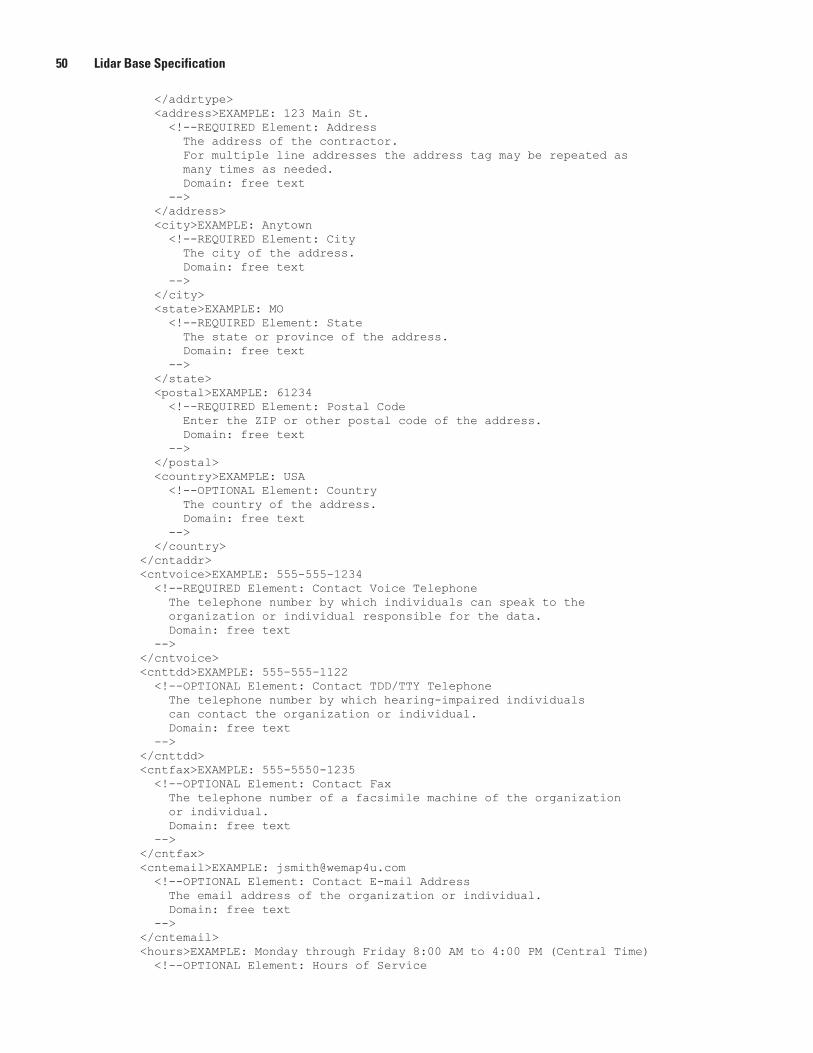
50 Lidar Base Specification
</addrtype> <address>EXAMPLE: 123 Main St. <!--REQUIRED Element: Address The address of the contractor. For multiple line addresses the address tag may be repeated as many times as needed. Domain: free text --> </address> <city>EXAMPLE: Anytown <!--REQUIRED Element: City The city of the address. Domain: free text --> </city> <state>EXAMPLE: MO <!--REQUIRED Element: State The state or province of the address. Domain: free text --> </state> <postal>EXAMPLE: 61234 <!--REQUIRED Element: Postal Code Enter the ZIP or other postal code of the address. Domain: free text --> </postal> <country>EXAMPLE: USA <!--OPTIONAL Element: Country The country of the address. Domain: free text --> </country> </cntaddr> <cntvoice>EXAMPLE: 555-555-1234 <!--REQUIRED Element: Contact Voice Telephone The telephone number by which individuals can speak to the organization or individual responsible for the data. Domain: free text --> </cntvoice> <cnttdd>EXAMPLE: 555-555-1122 <!--OPTIONAL Element: Contact TDD/TTY Telephone The telephone number by which hearing-impaired individuals can contact the organization or individual. Domain: free text --> </cnttdd> <cntfax>EXAMPLE: 555-5550-1235 <!--OPTIONAL Element: Contact Fax The telephone number of a facsimile machine of the organization or individual. Domain: free text --> </cntfax> <cntemail>EXAMPLE: [email protected] <!--OPTIONAL Element: Contact E-mail Address The email address of the organization or individual. Domain: free text --> </cntemail> <hours>EXAMPLE: Monday through Friday 8:00 AM to 4:00 PM (Central Time) <!--OPTIONAL Element: Hours of Service
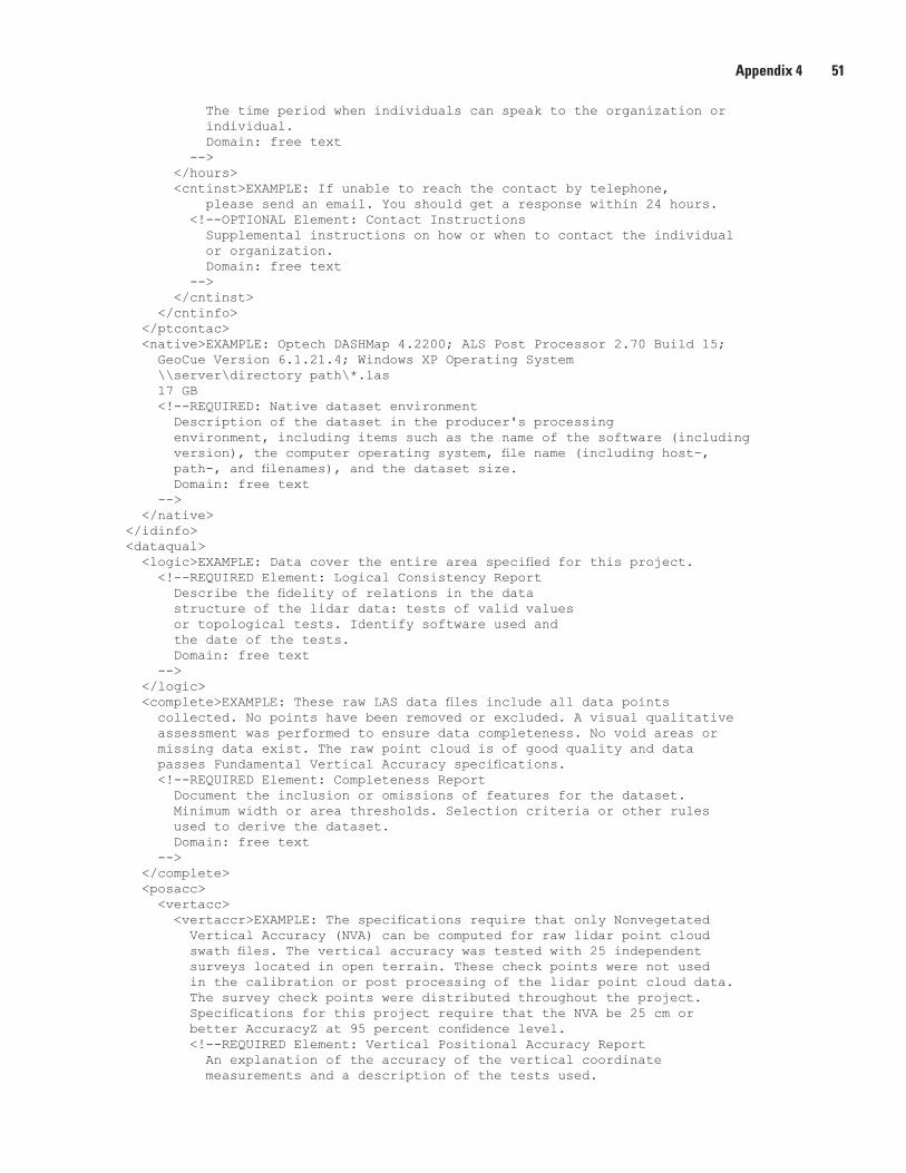
Appendix 4 51
The time period when individuals can speak to the organization or individual. Domain: free text --> </hours> <cntinst>EXAMPLE: If unable to reach the contact by telephone, please send an email. You should get a response within 24 hours. <!--OPTIONAL Element: Contact Instructions Supplemental instructions on how or when to contact the individual or organization. Domain: free text --> </cntinst> </cntinfo> </ptcontac> <native>EXAMPLE: Optech DASHMap 4.2200; ALS Post Processor 2.70 Build 15; GeoCue Version 6.1.21.4; Windows XP Operating System \\server\directory path\*.las 17 GB <!--REQUIRED: Native dataset environment Description of the dataset in the producer's processing environment, including items such as the name of the software (including version), the computer operating system, file name (including host-, path-, and filenames), and the dataset size. Domain: free text --> </native> </idinfo> <dataqual> <logic>EXAMPLE: Data cover the entire area specified for this project. <!--REQUIRED Element: Logical Consistency Report Describe the fidelity of relations in the data structure of the lidar data: tests of valid values or topological tests. Identify software used and the date of the tests. Domain: free text --> </logic> <complete>EXAMPLE: These raw LAS data files include all data points collected. No points have been removed or excluded. A visual qualitative assessment was performed to ensure data completeness. No void areas or missing data exist. The raw point cloud is of good quality and data passes Fundamental Vertical Accuracy specifications. <!--REQUIRED Element: Completeness Report Document the inclusion or omissions of features for the dataset. Minimum width or area thresholds. Selection criteria or other rules used to derive the dataset. Domain: free text --> </complete> <posacc> <vertacc> <vertaccr>EXAMPLE: The specifications require that only Nonvegetated Vertical Accuracy (NVA) can be computed for raw lidar point cloud swath files. The vertical accuracy was tested with 25 independent surveys located in open terrain. These check points were not used in the calibration or post processing of the lidar point cloud data. The survey check points were distributed throughout the project. Specifications for this project require that the NVA be 25 cm or better AccuracyZ at 95 percent confidence level. <!--REQUIRED Element: Vertical Positional Accuracy Report An explanation of the accuracy of the vertical coordinate measurements and a description of the tests used.
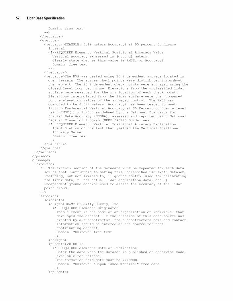
52 Lidar Base Specification
Domain: free text --> </vertaccr> <qvertpa> <vertaccv>EXAMPLE: 0.19 meters AccuracyZ at 95 percent Confidence Interval <!--REQUIRED Element: Vertical Positional Accuracy Value Vertical accuracy expressed in (ground) meters. Clearly state whether this value is RMSEz or AccuracyZ Domain: free text --> </vertaccv> <vertacce>The NVA was tested using 25 independent surveys located in open terrain. The survey check points were distributed throughout the project. The 25 independent check points were surveyed using the closed level loop technique. Elevations from the unclassified lidar surface were measured for the x,y location of each check point. Elevations interpolated from the lidar surface were then compared to the elevation values of the surveyed control. The RMSE was computed to be 0.097 meters. AccuracyZ has been tested to meet 19.0 cm Fundamental Vertical Accuracy at 95 Percent confidence level using RMSE(z) x 1.9600 as defined by the National Standards for Spatial Data Accuracy (NSSDA); assessed and reported using National Digital Elevation Program (NDEP)/ASRPS Guidelines. <!--REQUIRED Element: Vertical Positional Accuracy Explanation Identification of the test that yielded the Vertical Positional Accuracy Value. Domain: free text --> </vertacce> </qvertpa> </vertacc> </posacc> <lineage> <srcinfo> <!--The srcinfo section of the metadata MUST be repeated for each data source that contributed to making this unclassified LAS swath dataset, including, but not limited to, 1) ground control used for calibrating the lidar data, 2) the actual lidar acquisition data, and 3) independent ground control used to assess the accuracy of the lidar point cloud. --> <srccite> <citeinfo> <origin>EXAMPLE: Jiffy Survey, Inc <!--REQUIRED Element: Originator This element is the name of an organization or individual that developed the dataset. If the creation of this data source was created by a subcontractor, the subcontractors name and contact information should be entered as the source for that contributing dataset. Domain: "Unknown" free text --> </origin> <pubdate>20100115 <!--REQUIRED element: Date of Publication Enter the date when the dataset is published or otherwise made available for release. The format of this date must be YYYMMDD. Domain: "Unknown" "Unpublished material" free date --> </pubdate>
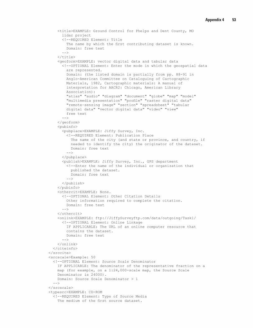
Appendix 4 53
<title>EXAMPLE: Ground Control for Phelps and Dent County, MO lidar project <!--REQUIRED Element: Title The name by which the first contributing dataset is known. Domain: free text --> </title> <geoform>EXAMPLE: vector digital data and tabular data <!--OPTIONAL Element: Enter the mode in which the geospatial data are represented. Domain: (the listed domain is partially from pp. 88-91 in Anglo-American Committee on Cataloguing of Cartographic Materials, 1982, Cartographic materials: A manual of interpretation for AACR2: Chicago, American Library Association): "atlas" "audio" "diagram" "document" "globe" "map" "model" "multimedia presentation" "profile" "raster digital data" "remote-sensing image" "section" "spreadsheet" "tabular digital data" "vector digital data" "video" "view" free text --> </geoform> <pubinfo> <pubplace>EXAMPLE: Jiffy Survey, Inc. <!--REQUIRED Element: Publication Place The name of the city (and state or province, and country, if needed to identify the city) the originator of the dataset. Domain: free text --> </pubplace> <publish>EXAMPLE: Jiffy Survey, Inc., GPS department <!--Enter the name of the individual or organization that published the dataset. Domain: free text --> </publish> </pubinfo> <othercit>EXAMPLE: None. <!--OPTIONAL Element: Other Citation Details Other information required to complete the citation. Domain: free text --> </othercit> <onlink>EXAMPLE: ftp://JiffySurveyftp.com/data/outgoing/Task1/ <!--OPTIONAL Element: Online Linkage IF APPLICABLE: The URL of an online computer resource that contains the dataset. Domain: free text --> </onlink> </citeinfo> </srccite> <srcscale>Example: 50 <!--OPTIONAL Element: Source Scale Denominator IF APPLICABLE: The denominator of the representative fraction on a map (for example, on a 1:24,000-scale map, the Source Scale Denominator is 24000). Domain: Source Scale Denominator > 1 --> </srcscale> <typesrc>EXAMPLE: CD-ROM <!--REQUIRED Element: Type of Source Media The medium of the first source dataset.
54 Lidar Base Specification
Domain: "paper" "stable-base material" "microfiche" "microfilm" "audiocassette" "chart" "filmstrip" "transparency" "videocassette" "videodisc" "videotape" "physical model" "computer program" "disc" "cartridge tape" "magnetic tape" "online" "CD-ROM" "electronic bulletin board" "electronic mail system" free text --> </typesrc> <srctime> <timeinfo> <sngdate> <caldate>201001003 <!--REQUIRED Element: Calendar Date This date is the date of the first source dataset was created. The field MUST be formatted YYYYMMDD --> </caldate> </sngdate> </timeinfo> <srccurr>EXAMPLE: ground condition <!--REQUIRED Element: Source Currentness Reference The basis on which the source time period of content information of the source dataset is determined. Domain: "ground condition" "publication date" free text --> </srccurr> </srctime> <srccitea>EXAMPLE: Phelps_Co_lidar_gnd_ctrl <!--REQUIRED Element: Source Citation Abbreviation Enter short-form alias for the source citation. Each source MUST HAVE A UNIQUE ID. This ID will be used to reference these source data in the Process Step sections below. Domain: free text --> </srccitea> <srccontr>EXAMPLE: This data source was used (along with the airborne GPS/IMU Data) to georeferencing of the lidar point cloud data. <!--REQUIRED Element: Source Contribution Brief statement identifying the information contributed. Domain: free text --> </srccontr> </srcinfo> <srcinfo> <srccite> <citeinfo> <origin>USDA</origin> <pubdate>20090606</pubdate> <title>NAIP Imagery for Phelps and Dent County, MO lidar project </title> <geoform>raster orthoimagery</geoform> <pubinfo> <pubplace>USGS-EROS</pubplace> <publish>USGS-EROS</publish> </pubinfo> <othercit>None</othercit> <onlink></onlink> </citeinfo> </srccite> <srcscale>50</srcscale> <typesrc>online</typesrc> <srctime> <timeinfo> <sngdate>
Appendix 4 55
<caldate>20090101</caldate> </sngdate> </timeinfo> <srccurr>ground condition</srccurr> </srctime> <srccitea>Phelps-Dent_Co_NAIP_Imagery</srccitea> <srccontr>This data source was used (along with the lidar intensity imagery) to classify the lidar point cloud data. </srccontr> </srcinfo> <srcinfo> <srccite> <citeinfo> <origin>We Map 4U, Inc.</origin> <pubdate>20101208</pubdate> <title>Lidar Intensity Imagery for Phelps and Dent County, MO </title> <geoform>raster orthoimagery</geoform> <pubinfo> <pubplace>USGS-EROS</pubplace> <publish>USGS-EROS</publish> </pubinfo> <othercit>None</othercit> <onlink></onlink> </citeinfo> </srccite> <srcscale>50</srcscale> <typesrc>online</typesrc> <srctime> <timeinfo> <rngdates> <begdate>20100216</begdate> <enddate>20100218</enddate> </rngdates> </timeinfo> <srccurr>ground condition</srccurr> </srctime> <srccitea>Phelps-Dent_Co_Lidar_Intensity_Imagery</srccitea> <srccontr>This data source was used (along with NAIP imagery) to classify the lidar point cloud data. </srccontr> </srcinfo> <procstep> <procdesc>EXAMPLE: Lidar Preprocessing: Airborne GPS and IMU data were merged to develop a Single Best Estimate (SBET) of the lidar system trajectory for each lift. Lidar ranging data were initially calibrated using previous best parameters for this instrument and aircraft. Relative calibration was evaluated using advanced plane-matching analysis and parameter corrections derived. This process was repeated iteratively until residual errors between overlapping swaths, across all project lifts, was reduced to 2 cm or less. Data were then block adjusted to match surveyed calibration control. Raw data NVA were checked using independently surveyed check points. Swath overage points were identified and tagged within each swath file. <!--Enter an explanation of the event and related parameters or tolerances. Domain: free text --> </procdesc> <srcused>EXAMPLE: Phelps_Co_lidar_gnd_ctrl <!--Enter the Source Citation Abbreviation of a dataset used in the processing step. Domain: Source Citation Abbreviations from the Source Information entries for the dataset.
56 Lidar Base Specification
--> </srcused> <procdate>20100131 <!--Enter the date when the event was completed. Domain: "Unknown" "Not complete" free date --> </procdate> <srcprod>EXAMPLE: Lidar datasets with USGS classifications <!--Enter the Source Citation Abbreviation of an intermediate dataset that (1) is significant in the opinion of the data producer, (2) is generated in the processing step, and (3) is used in later processing steps. Domain: Source Citation Abbreviations from the Source Information entries for the dataset. --> </srcprod> <proccont> <cntinfo> <cntorgp> <cntorg>EXAMPLE: We Map 4U, Data Acquisition Department <!--Enter the name of the organization to which the contact type applies. Domain: free text --> </cntorg> <cntper>EXAMPLE: Manny Puntas <!--Enter the name of the individual to which the contact type applies. Domain: free text --> </cntper> </cntorgp> <cntaddr> <addrtype>mailing and physical</addrtype> <address>123 Main St.</address> <city>Anytown</city> <state>MO</state> <postal>61234</postal> <country>USA</country> </cntaddr> <cntvoice>555-555-556</cntvoice> <cntfax>555-5550-1236</cntfax> <cntemail>[email protected]</cntemail> <hours>Monday through Friday 8:00 AM to 4:00 PM (Central Time) </hours> <cntinst>If unable to reach the contact by telephone, please send an email. You should get a response within 24 hours. </cntinst> </cntinfo> </proccont> </procstep> <procstep> <procdesc>Lidar Post-Processing: The calibrated and controlled lidar swaths were processed using automatic point classification routines in proprietary software. These routines operate against the entire collection (all swaths, all lifts), eliminating character differences between files. Data were then distributed as virtual tiles to experienced lidar analysts for localized automatic classification, manual editing, and peer-based QC checks. Supervisory QC monitoring of work in progress and completed editing ensured consistency of classification character and adherence to project requirements across the entire project. All classification tags are stored in the original swath files. After completion of classification and final QC approval,
Appendix 4 57
the NVA and VVA for the project are calculated. Sample areas for each land cover type present in the project were extracted and forwarded to the client, along with the results of the accuracy tests. Upon acceptance, the complete classified lidar swath files were delivered to the client. </procdesc> <srcused>Phelps-Dent_Co_NAIP_Imagery</srcused> <srcused>Phelps-Dent_Co_Lidar_Intensity_Imagery</srcused> <procdate>20100530</procdate> <proccont> <cntinfo> <cntorgp> <cntorg>We Map 4U, Data Acquisition Department</cntorg> <cntper>Manny Puntas</cntper> </cntorgp> <cntaddr> <addrtype>mailing and physical</addrtype> <address>123 Main St.</address> <city>Anytown</city> <state>MO</state> <postal>61234</postal> <country>USA</country> </cntaddr> <cntvoice>555-555-556</cntvoice> <cntfax>555-5550-1236</cntfax> <cntemail>[email protected]</cntemail> <hours>Monday through Friday 8:00 AM to 4:00 PM (Central Time) </hours> <cntinst>If unable to reach the contact by telephone, please send an email. You should get a response within 24 hours. </cntinst> </cntinfo> </proccont> </procstep> </lineage> </dataqual> <spdoinfo> <direct>EXAMPLE: Vector <!--REQUIRED Element: Enter the system of objects used to represent space in the dataset. Domain: "Point" "Vector" "Raster" --> </direct> <ptvctinf> <sdtsterm> <sdtstype>EXAMPLE: Point <!--REQUIRED Element: SDTS Point and Vector Object Type Enter name of point and vector spatial objects used to locate zero-, one-, and two-dimensional spatial locations in the dataset. Domain: (The domain is from "Spatial Data Concepts," which is Chapter 2 of Part 1 in Department of Commerce, 1992, Spatial Data Transfer Standard (SDTS) (Federal Information Processing Standard 173): Washington, Department of Commerce, National Institute of Standards and Technology): "Point" --> </sdtstype> <ptvctcnt>EXAMPLE: 764,567,423 <!--OPTIONAL Element: Point and Vector Count Enter the total number of the point or vector object type occurring in the dataset. Domain: Point and Vector Object Count > 0 -->
58 Lidar Base Specification
</ptvctcnt> </sdtsterm> </ptvctinf> </spdoinfo> <spref> <horizsys> <planar> <gridsys> <!--REQUIRED Section: The section should be filled out with the relevant parameters for the coordinate reference system for the data. Usually it will be UTM or a State Plane Zone. Delete the irrelevant section below. --> <gridsysn>EXAMPLE: Universal Transverse Mercator <!--Enter name of the grid coordinate system. Domain: "Universal Transverse Mercator" "Universal Polar Stereographic" "State Plane Coordinate System 1927" "State Plane Coordinate System 1983" "ARC Coordinate System" "other grid system" --> </gridsysn> <utm> <utmzone>EXAMPLE: 15 <!--Enter the identifier for the UTM zone. Type: integer Domain: 1 <= UTM Zone Number <= 60 for the northern hemisphere; -60 <= UTM Zone Number <= -1 for the southern hemisphere --> </utmzone> <transmer> <sfctrmer>0.9996 <!--Enter a multiplier for reducing a distance obtained from a map by computation or scaling to the actual distance along the Central Meridian. Domain: Scale Factor at Central Meridian > 0.0 --> </sfctrmer> <longcm>-117.000000 <!--Enter the line of longitude at the center of a map projection generally used as the basis for constructing the projection. Type: real Domain: -180.0 <= Longitude of Central Meridian < 180.0 --> </longcm> <latprjo>0.0 <!--Enter latitude chosen as the origin of rectangular coordinates for a map projection. Domain: -90.0 <= Latitude of Projection Origin <= 90.0 --> </latprjo> <feast>500000 <!--Enter the value added to all "x" values in the rectangular coordinates for a map projection. This value is frequently assigned to eliminate negative numbers. Expressed in the unit of measure identified in Planar Coordinate Units. Domain: free real --> </feast>
Appendix 4 59
<fnorth>0.0 <!--Enter the value added to all "y" values in the rectangular coordinates for a map projection. This value is frequently assigned to eliminate negative numbers. Expressed in the unit of measure identified in Planar Coordinate Units. Domain: free real --> </fnorth> </transmer> </utm> <spcs> <spcszone> <!--Enter identifier for the SPCS zone. Domain: Four-digit numeric codes for the State Plane Coordinate Systems based on the North American Datum of 1927 are documented in Department of Commerce, 1986, Representation of geographic information interchange (Federal Information Processing Standard 70-1): Washington: Department of Commerce, National Institute of Standards and Technology. Codes for the State Plane Coordinate Systems based on the North American Datum of 1983 are documented in Department of Commerce, 1989 (January), State Plane Coordinate System of 1983 (National Oceanic and Atmospheric Administration Manual NOS NGS 5): Silver Spring MD, National Oceanic and Atmospheric Administration, National Ocean Service, Coast and Geodetic Survey. --> </spcszone> <lambertc> <stdparll> <!--Enter line of constant latitude at which the surface of the Earth and the plane of projection intersect. Domain: -90.0 <= Standard Parallel <= 90.0 --> </stdparll> <longcm> <!--Enter the line of longitude at the center of a map projection generally used as the basis for constructing the projection. Domain: -180.0 <= Longitude of Central Meridian < 180.0 --> </longcm> <latprjo> <!--Enter latitude chosen as the origin of rectangular coordinates for a map projection. Domain: -90.0 <= Latitude of Projection Origin <= 90.0 --> </latprjo> <feast> <!--Enter the value added to all "x" values in the rectangular coordinates for a map projection. This value is frequently assigned to eliminate negative numbers. Expressed in the unit of measure identified in Planar Coordinate Units. Domain: free real --> </feast> <fnorth> <!--Enter the value added to all "y" values in the rectangular coordinates for a map projection. This value frequently is assigned to eliminate negative numbers. Expressed in the unit of measure identified in Planar Coordinate Units. Domain: free real --> </fnorth>
60 Lidar Base Specification
</lambertc> <transmer> <sfctrmer> <!--Enter a multiplier for reducing a distance obtained from a map by computation or scaling to the actual distance along the central meridian. Domain: Scale Factor at Central Meridian > 0.0 --> </sfctrmer> <longcm> <!--Enter the line of longitude at the center of a map projection generally used as the basis for constructing the projection. Type: real Domain: -180.0 <= Longitude of Central Meridian < 180.0 --> </longcm> <latprjo> <!--Enter latitude chosen as the origin of rectangular coordinates for a map projection. Domain: -90.0 <= Latitude of Projection Origin <= 90.0 --> </latprjo> <feast> <!--Enter the value added to all "x" values in the rectangular coordinates for a map projection. This value is frequently assigned to eliminate negative numbers. Expressed in the unit of measure identified in Planar Coordinate Units. Domain: free real --> </feast> <fnorth> <!--Enter the value added to all "y" values in the rectangular coordinates for a map projection. This value is frequently assigned to eliminate negative numbers. Expressed in the unit of measure identified in Planar Coordinate Units. Domain: free real --> </fnorth> </transmer> <obqmerc> <sfctrlin> <!--Enter a multiplier for reducing a distance obtained from a map by computation or scaling to the actual distance along the center line. Domain: Scale Factor at Center Line > 0.0 --> </sfctrlin> <obqlazim> <azimangl> <!--Enter angle measured clockwise from north, and expressed in degrees. Domain: 0.0 <= Azimuthal Angle < 360.0 --> </azimangl> <azimptl> <!--Enter longitude of the map projection origin. Domain: -180.0 <= Azimuth Measure Point Longitude < 180.0 --> </azimptl> </obqlazim> <obqlpt> <obqllat>
Appendix 4 61
<!--Enter latitude of a point defining the oblique line. Domain: -90.0 <= Oblique Line Latitude <= 90.0 --> </obqllat> <obqllong> <!--Enter longitude of a point defining the oblique line. Domain: -180.0 <= Oblique Line Longitude < 180.0 --> </obqllong> </obqlpt> <latprjo> <!--Enter latitude chosen as the origin of rectangular coordinates for a map projection. Domain: -90.0 <= Latitude of Projection Origin <= 90.0 --> </latprjo> <feast> <!--Enter the value added to all "x" values in the rectangular coordinates for a map projection. This value is frequently assigned to eliminate negative numbers. Expressed in the unit of measure identified in Planar Coordinate Units. Domain: free real --> </feast> <fnorth> <!--Enter the value added to all "y" values in the rectangular coordinates for a map projection. This value is frequently assigned to eliminate negative numbers. Expressed in the unit of measure identified in Planar Coordinate Units. Domain: free real --> </fnorth> </obqmerc> <polycon> <longcm> <!--Enter the line of longitude at the center of a map projection generally used as the basis for constructing the projection. Domain: -180.0 <= Longitude of Central Meridian < 180.0 --> </longcm> <latprjo> <!--Enter latitude chosen as the origin of rectangular coordinates for a map projection. Domain: -90.0 <= Latitude of Projection Origin <= 90.0 --> </latprjo> <feast> <!--Enter the value added to all "x" values in the rectangular coordinates for a map projection. This value is frequently assigned to eliminate negative numbers. Expressed in the unit of measure identified in Planar Coordinate Units. Domain: free real --> </feast> <fnorth> <!--Enter the value added to all "y" values in the rectangular coordinates for a map projection. This value is frequently assigned to eliminate negative numbers. Expressed in the unit of measure identified in Planar Coordinate Units. Domain: free real --> </fnorth>
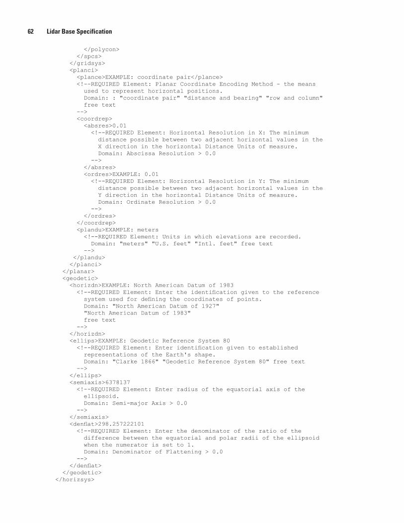
62 Lidar Base Specification
</polycon> </spcs> </gridsys> <planci> <plance>EXAMPLE: coordinate pair</plance> <!--REQUIRED Element: Planar Coordinate Encoding Method - the means used to represent horizontal positions. Domain: : "coordinate pair" "distance and bearing" "row and column" free text --> <coordrep> <absres>0.01 <!--REQUIRED Element: Horizontal Resolution in X: The minimum distance possible between two adjacent horizontal values in the X direction in the horizontal Distance Units of measure. Domain: Abscissa Resolution > 0.0 --> </absres> <ordres>EXAMPLE: 0.01 <!--REQUIRED Element: Horizontal Resolution in Y: The minimum distance possible between two adjacent horizontal values in the Y direction in the horizontal Distance Units of measure. Domain: Ordinate Resolution > 0.0 --> </ordres> </coordrep> <plandu>EXAMPLE: meters <!--REQUIRED Element: Units in which elevations are recorded. Domain: "meters" "U.S. feet" "Intl. feet" free text --> </plandu> </planci> </planar> <geodetic> <horizdn>EXAMPLE: North American Datum of 1983 <!--REQUIRED Element: Enter the identification given to the reference system used for defining the coordinates of points. Domain: "North American Datum of 1927" "North American Datum of 1983" free text --> </horizdn> <ellips>EXAMPLE: Geodetic Reference System 80 <!--REQUIRED Element: Enter identification given to established representations of the Earth's shape. Domain: "Clarke 1866" "Geodetic Reference System 80" free text --> </ellips> <semiaxis>6378137 <!--REQUIRED Element: Enter radius of the equatorial axis of the ellipsoid. Domain: Semi-major Axis > 0.0 --> </semiaxis> <denflat>298.257222101 <!--REQUIRED Element: Enter the denominator of the ratio of the difference between the equatorial and polar radii of the ellipsoid when the numerator is set to 1. Domain: Denominator of Flattening > 0.0 --> </denflat> </geodetic> </horizsys>
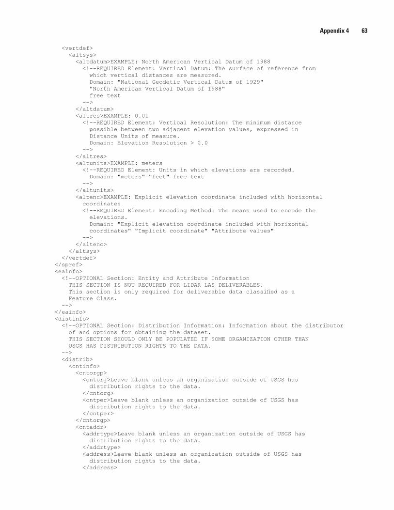
Appendix 4 63
<vertdef> <altsys> <altdatum>EXAMPLE: North American Vertical Datum of 1988 <!--REQUIRED Element: Vertical Datum: The surface of reference from which vertical distances are measured. Domain: "National Geodetic Vertical Datum of 1929" "North American Vertical Datum of 1988" free text --> </altdatum> <altres>EXAMPLE: 0.01 <!--REQUIRED Element: Vertical Resolution: The minimum distance possible between two adjacent elevation values, expressed in Distance Units of measure. Domain: Elevation Resolution > 0.0 --> </altres> <altunits>EXAMPLE: meters <!--REQUIRED Element: Units in which elevations are recorded. Domain: "meters" "feet" free text --> </altunits> <altenc>EXAMPLE: Explicit elevation coordinate included with horizontal coordinates <!--REQUIRED Element: Encoding Method: The means used to encode the elevations. Domain: "Explicit elevation coordinate included with horizontal coordinates" "Implicit coordinate" "Attribute values" --> </altenc> </altsys> </vertdef> </spref> <eainfo> <!--OPTIONAL Section: Entity and Attribute Information THIS SECTION IS NOT REQUIRED FOR LIDAR LAS DELIVERABLES. This section is only required for deliverable data classified as a Feature Class. --> </eainfo> <distinfo> <!--OPTIONAL Section: Distribution Information: Information about the distributor of and options for obtaining the dataset. THIS SECTION SHOULD ONLY BE POPULATED IF SOME ORGANIZATION OTHER THAN USGS HAS DISTRIBUTION RIGHTS TO THE DATA. --> <distrib> <cntinfo> <cntorgp> <cntorg>Leave blank unless an organization outside of USGS has distribution rights to the data. </cntorg> <cntper>Leave blank unless an organization outside of USGS has distribution rights to the data. </cntper> </cntorgp> <cntaddr> <addrtype>Leave blank unless an organization outside of USGS has distribution rights to the data. </addrtype> <address>Leave blank unless an organization outside of USGS has distribution rights to the data. </address>
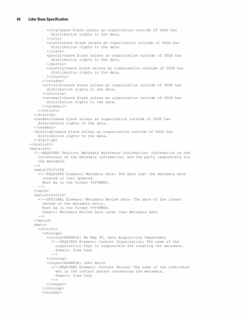
64 Lidar Base Specification
<city>Leave blank unless an organization outside of USGS has distribution rights to the data. </city> <state>Leave blank unless an organization outside of USGS has distribution rights to the data. </state> <postal>Leave blank unless an organization outside of USGS has distribution rights to the data. </postal> <country>Leave blank unless an organization outside of USGS has distribution rights to the data. </country> </cntaddr> <cntvoice>Leave blank unless an organization outside of USGS has distribution rights to the data. </cntvoice> <cntemail>Leave blank unless an organization outside of USGS has distribution rights to the data. </cntemail> </cntinfo> </distrib> <resdesc>Leave blank unless an organization outside of USGS has distribution rights to the data. </resdesc> <distliab>Leave blank unless an organization outside of USGS has distribution rights to the data. </distliab> </distinfo> <metainfo> <!--REQUIRED Section: Metadata Reference Information: Information on the currentness of the metadata information, and the party responsible for the metadata. --> <metd>20101206 <!--REQUIRED Element: Metadata Date: The date that the metadata were created or last updated. Must be in the format YYYYMMDD. --> </metd> <metrd>20101207 <!--OPTIONAL Element: Metadata Review Date: The date of the latest review of the metadata entry. Must be in the format YYYYMMDD. Domain: Metadata Review Date later than Metadata Date --> </metrd> <metc> <cntinfo> <cntorgp> <cntorg>EXAMPLE: We Map 4U, Data Acquisition Department <!--REQUIRED Element: Contact Organization: The name of the organization that is responsible for creating the metadata. Domain: free text --> </cntorg> <cntper>EXAMPLE: John Smith <!--REQUIRED Element: Contact Person: The name of the individual who is the contact person concerning the metadata. Domain: free text --> </cntper> </cntorgp> <cntaddr>
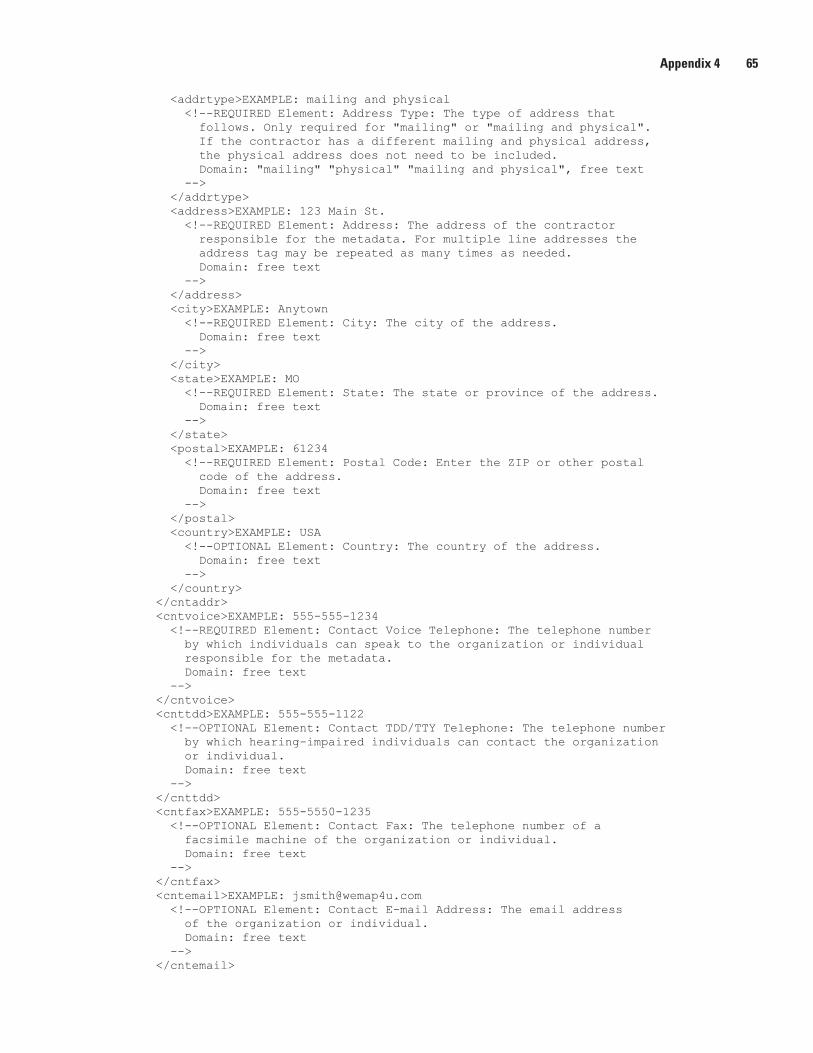
Appendix 4 65
<addrtype>EXAMPLE: mailing and physical <!--REQUIRED Element: Address Type: The type of address that follows. Only required for "mailing" or "mailing and physical". If the contractor has a different mailing and physical address, the physical address does not need to be included. Domain: "mailing" "physical" "mailing and physical", free text --> </addrtype> <address>EXAMPLE: 123 Main St. <!--REQUIRED Element: Address: The address of the contractor responsible for the metadata. For multiple line addresses the address tag may be repeated as many times as needed. Domain: free text --> </address> <city>EXAMPLE: Anytown <!--REQUIRED Element: City: The city of the address. Domain: free text --> </city> <state>EXAMPLE: MO <!--REQUIRED Element: State: The state or province of the address. Domain: free text --> </state> <postal>EXAMPLE: 61234 <!--REQUIRED Element: Postal Code: Enter the ZIP or other postal code of the address. Domain: free text --> </postal> <country>EXAMPLE: USA <!--OPTIONAL Element: Country: The country of the address. Domain: free text --> </country> </cntaddr> <cntvoice>EXAMPLE: 555-555-1234 <!--REQUIRED Element: Contact Voice Telephone: The telephone number by which individuals can speak to the organization or individual responsible for the metadata. Domain: free text --> </cntvoice> <cnttdd>EXAMPLE: 555-555-1122 <!--OPTIONAL Element: Contact TDD/TTY Telephone: The telephone number by which hearing-impaired individuals can contact the organization or individual. Domain: free text --> </cnttdd> <cntfax>EXAMPLE: 555-5550-1235 <!--OPTIONAL Element: Contact Fax: The telephone number of a facsimile machine of the organization or individual. Domain: free text --> </cntfax> <cntemail>EXAMPLE: [email protected] <!--OPTIONAL Element: Contact E-mail Address: The email address of the organization or individual. Domain: free text --> </cntemail>
66 Lidar Base Specification
<hours>EXAMPLE: Monday through Friday 8:00 AM to 4:00 PM (Central Time) <!--OPTIONAL Element: Hours of Service: The time period when individuals can speak to the organization or individual. Domain: free text --> </hours> <cntinst>EXAMPLE: If unable to reach the contact by telephone, please send an email. You should get a response within 24 hours. <!--OPTIONAL Element: Contact Instructions: Supplemental instructions on how or when to contact the individual or organization. Domain: free text --> </cntinst> </cntinfo> </metc> <metstdn>EXAMPLE: FGDC Content Standard for Digital Geospatial Metadata <!--REQUIRED Element: Metadata Standard: Enter the name of the metadata standard used to document the dataset. Domain: "FGDC Content Standard for Digital Geospatial Metadata" free text --> </metstdn> <metstdv>EXAMPLE: FGDC-STD-001-1998 <!--REQUIRED Element: Metadata Standard Version. Enter identification of the version of the metadata standard used to document the dataset. Domain: free text --> </metstdv> <metac>EXAMPLE: None. <!--OPTIONAL Element: Metadata Access Constraints: Restrictions and legal prerequisites for accessing the metadata. These include any access constraints applied to assure the protection of privacy or intellectual property, and any special restrictions or limitations on obtaining the metadata. Domain: free text --> </metac> <metuc>EXAMPLE: None. <!--OPTIONAL Element: Metadata Use Constraints: Restrictions and legal prerequisites for using the metadata after access is granted. These include any metadata use constraints applied to assure the protection of privacy or intellectual property, and any special restrictions or limitations on using the metadata. Domain: free text --> </metuc> <metsi> <metscs>EXAMPLE: None. <!--REQUIRED IF APPLICABLE: Metadata Security Classification System: Name of the classification system for the metadata. Domain: free text --> </metscs> <metsc>EXAMPLE: Unclassified <!--REQUIRED IF APPLICABLE: Metadata Security Classification: Name of the handling restrictions on the metadata. Domain: "Top secret" "Secret" "Confidential" "Restricted" "Unclassified" "Sensitive" free text --> </metsc> <metshd>EXAMPLE: NONE <!--REQUIRED IF APPLICABLE: Metadata Security Handling Description: Additional information about the restrictions on handling the metadata.
Appendix 4 67
Domain: free text --> </metshd> </metsi> <metextns> <!--Metadata Extensions Group: REQUIRED IF APPLICABLE. A reference to extended elements to the standard that may be defined by a metadata producer or a user community. Extended elements are elements outside the Standard, but needed by the metadata producer. If extended elements are created, they must follow the guidelines in Appendix D, Guidelines for Creating Extended Elements to the Content Standard for Digital Geospatial Metadata. --> <!--This section may be repeated as necessary--> <onlink>EXAMPLE: None <!--REQUIRED IF APPLICABLE: Online Linkage: URL for the resource that contains the metadata extension information for the dataset. --> </onlink> <metprof>EXAMPLE: None <!--REQUIRED IF APPLICABLE: Profile Name: Name of a document that describes the application of the Standard to a specific user community. --> </metprof> </metextns> </metainfo></metadata>


Publishing support provided by: Rolla and Tacoma Publishing Service Centers
For more information concerning this publication, contact: U.S. Geological Survey Earth Resources Observation and Science (EROS) Center 47914 252nd Street Sioux Falls, South Dakota 57198 (605) 594-6151
Or visit the EROS Center Web site at:http://eros.usgs.gov/
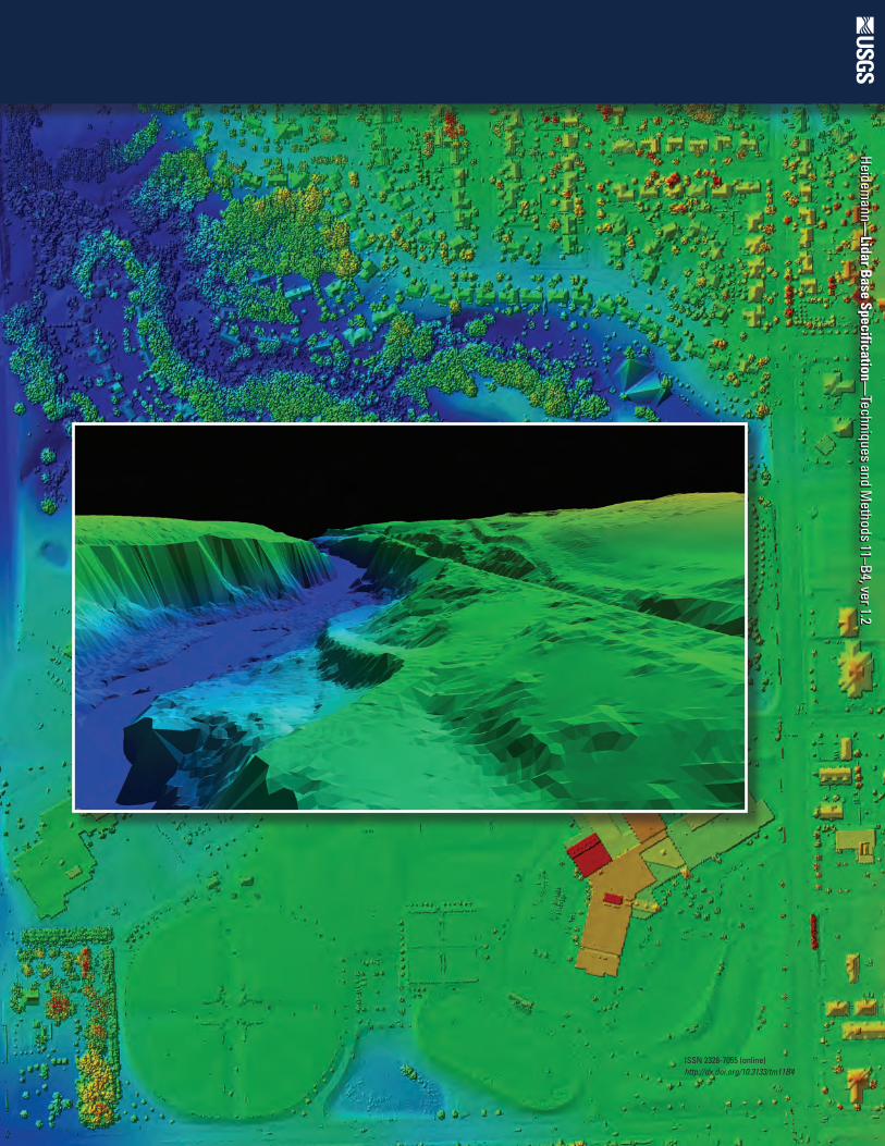
Heidemann—
Lidar Base Specification—
Techniques and Methods 11–B4, ver 1.2
Heidemann—
Lidar Base Specification—
Techniques and Methods 11–B4, ver 1.2
ISSN 2328-7055 (online)http://dx.doi.org/10.3133/tm11B4


![0 QL IA e,;;; - · PDF fileties of and i [pls. of ; and i ]. (TA.) - And Small herbage: (1 :) [or] a sort of ... 0 0Jet * :*l34,5 s JL otfl i*s,6:QL IA 0 [O0 my people,](https://img.pdfslide.us/doc/110x75/5a79dd817f8b9ad7608d63c1/0-ql-ia-e-of-and-i-pls-of-and-i-ta-and-small-herbage-1-or.jpg)