Embed Size (px)
Citation preview
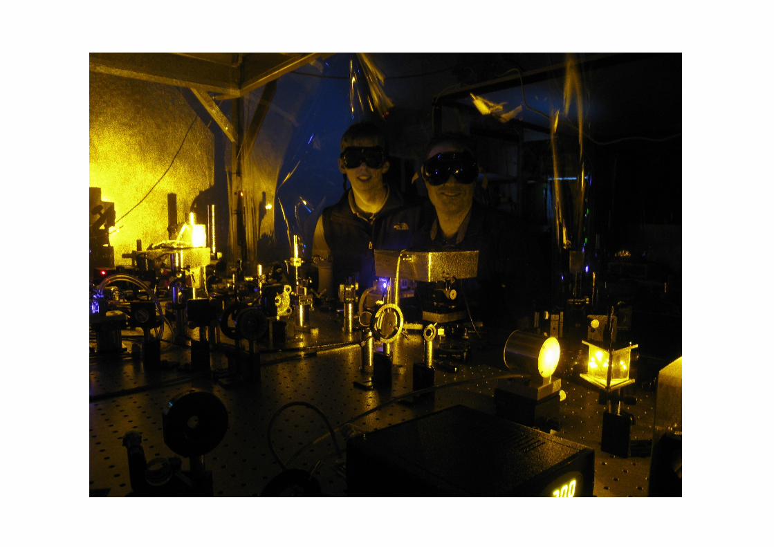
CTA Workshop, 30 Sept 2013
Peter Veitch for the Optics & Photonics Group
Department of Physics, University of Adelaide
Lidar at Adelaide
Coherent Lidar Water Vapour DIAL Rayleigh/Raman/Fe-Boltzmann Lidar Na Guide-Star Laser
Contents

Nick Chang, Myles Clark, Alex Dinovitser, Murray Hamilton,
Lachlan Harris, Matthew Heintze, David Hosken, Andrew
MacKinnon, Jesper Munch, David Ottaway, Iain Reid, Tom Rutten,
Nikita Simakov, Liam Twigger, Peter Veitch, Bob Vincent, …
People

Coherent Laser Radar System
pulsed
Initally: diode-pumped Er:Yb:glass (0.5 mJ, 2 Hz, 1535 nm) Now: diode-pumped Er:YAG (10-20 mJ, 1 kHz, 1645 nm)
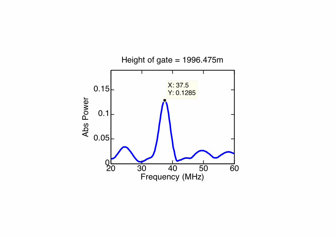
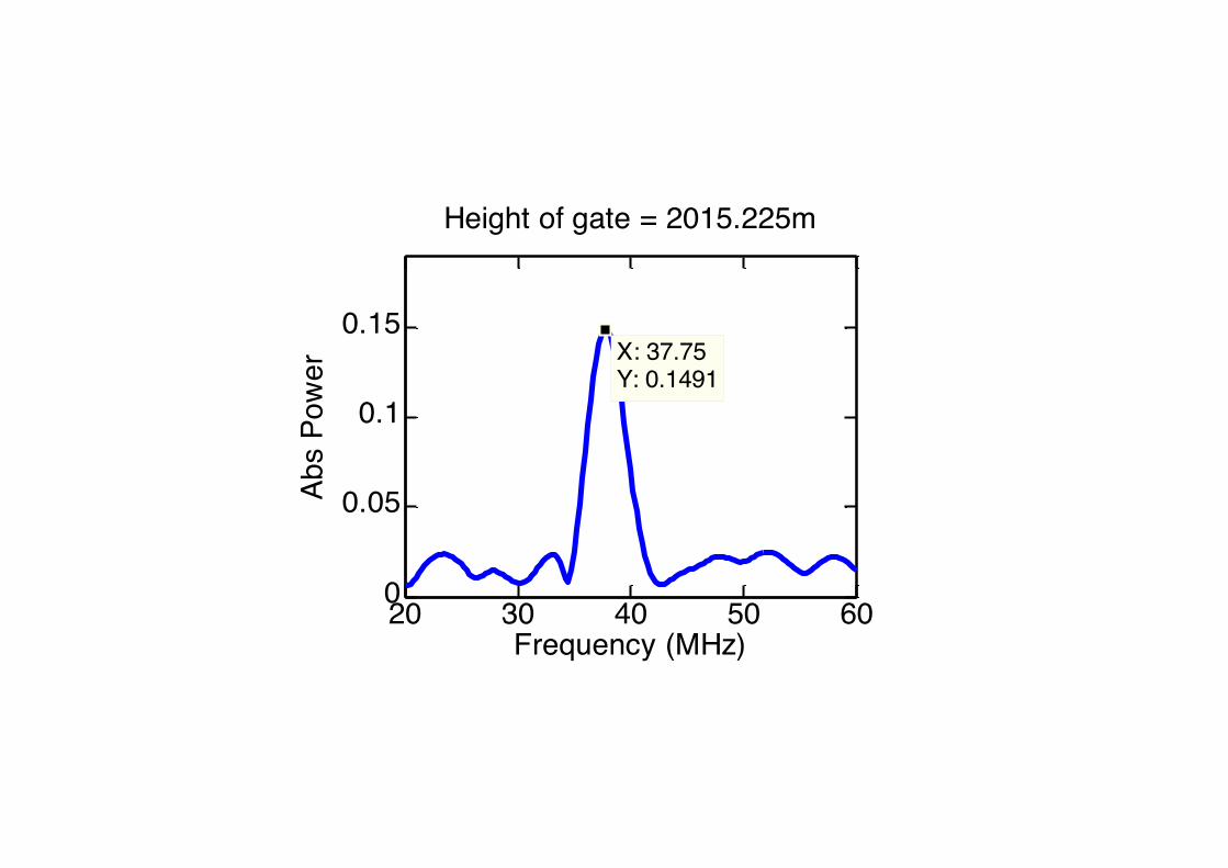
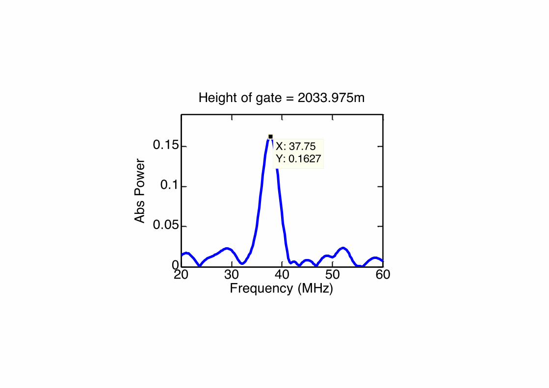
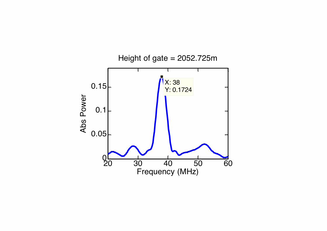
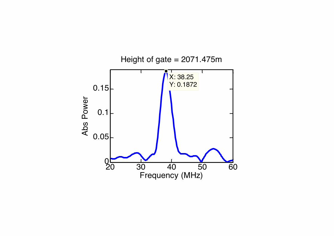
An example of a wind-speed measurement
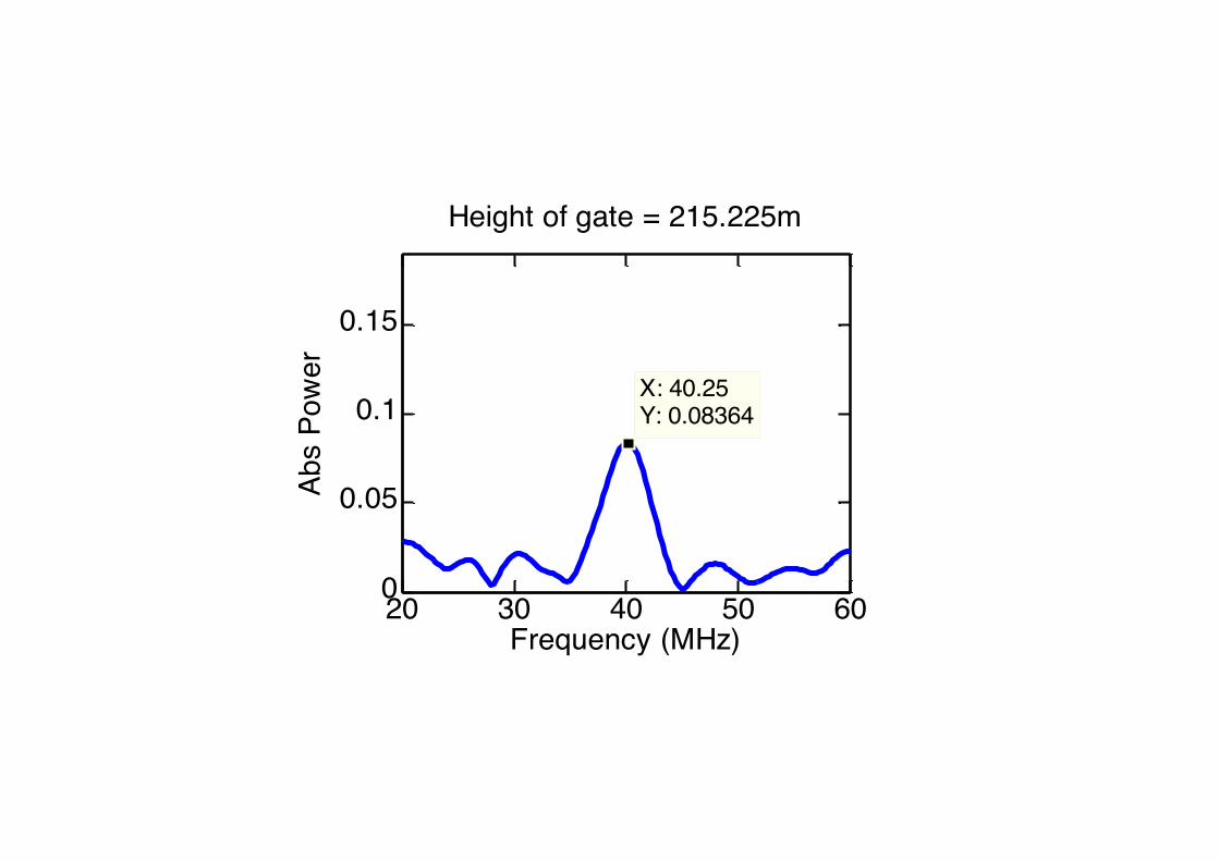
• Er:Yb:glass slave laser
• Pulse energy: 0.5 mJ
• Direction: 12º from zenith
• 500-sample range gates (500 ns duration, 75% overlap)
• 3500 sample zero padding → 0.25 MHz bins
• Single shot (no averaging)
• Spectra for range gates in which no signal usually not shown
• Statistically significant peaks in spectra are labeled
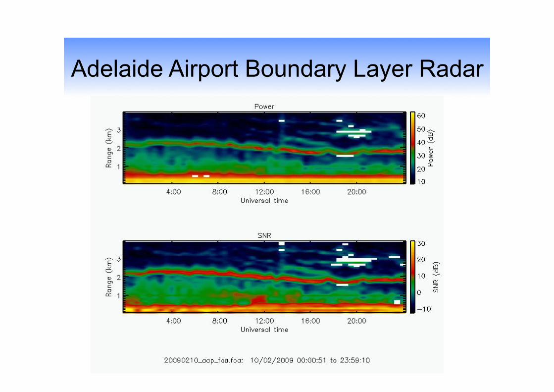
Adelaide Airport Boundary Layer Radar
0 0.5 1 1.5 2x 10⁻⁶
-0.4
-0.2
0
0.2
0.4Reference Trace
Time (s)
Ref
eren
ce S
igna
l (V)
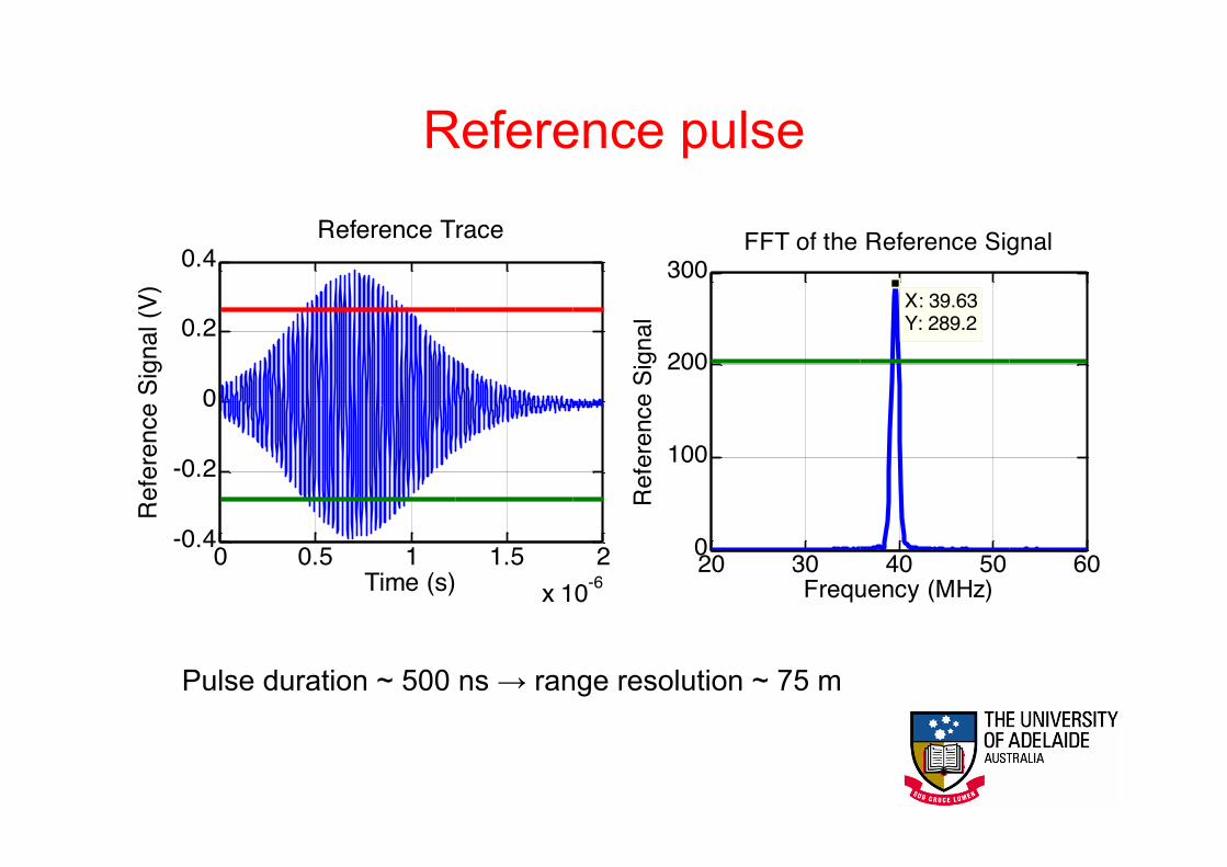
Pulse duration ~ 500 ns → range resolution ~ 75 m
20 30 40 50 600
100
200
300X: 39.63Y: 289.2
FFT of the Reference Signal
Frequency (MHz)
Ref
eren
ce S
igna
l
Reference pulse
20 30 40 50 600
0.05
0.1
0.15
X: 40.25Y: 0.08364
Frequency (MHz)
Abs
Pow
er
Height of gate = 215.225m
20 30 40 50 600
0.05
0.1
0.15
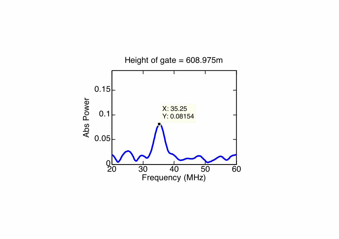
X: 35.25Y: 0.08154
Frequency (MHz)
Abs
Pow
er
Height of gate = 608.975m
20 30 40 50 600
0.05
0.1
0.15 X: 37.5Y: 0.1285
Frequency (MHz)
Abs
Pow
er
Height of gate = 1996.475m
20 30 40 50 600
0.05
0.1
0.15X: 37.75Y: 0.1491
Frequency (MHz)
Abs
Pow
er
Height of gate = 2015.225m
20 30 40 50 600
0.05
0.1
0.15 X: 37.75Y: 0.1627
Frequency (MHz)
Abs
Pow
er
Height of gate = 2033.975m
20 30 40 50 600
0.05
0.1
0.15 X: 38Y: 0.1724
Frequency (MHz)
Abs
Pow
er
Height of gate = 2052.725m
20 30 40 50 600
0.05
0.1
0.15X: 38.25Y: 0.1872
Frequency (MHz)
Abs
Pow
er
Height of gate = 2071.475m
20 30 40 50 600
0.05
0.1
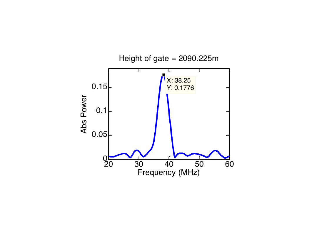
0.15X: 38.25Y: 0.1776
Frequency (MHz)
Abs
Pow
er
Height of gate = 2090.225m

20 30 40 50 600
0.05
0.1
0.15X: 38.25Y: 0.1435
Frequency (MHz)
Abs
Pow
er
Height of gate = 2108.975m
20 30 40 50 600
0.05
0.1
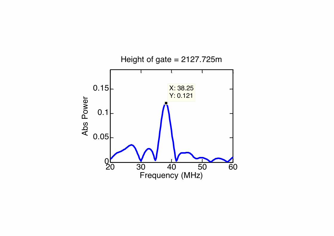
0.15 X: 38.25Y: 0.121
Frequency (MHz)
Abs
Pow
er
Height of gate = 2127.725m
20 30 40 50 600
0.05
0.1
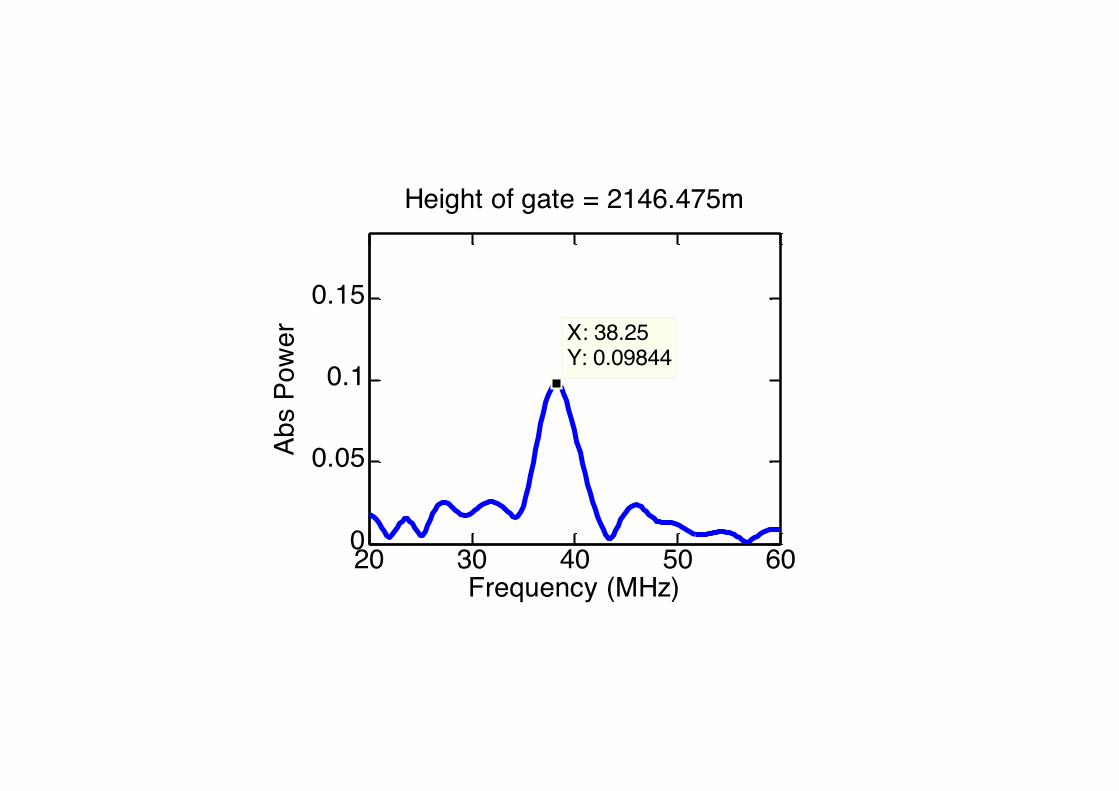
0.15X: 38.25Y: 0.09844
Frequency (MHz)
Abs
Pow
er
Height of gate = 2146.475m
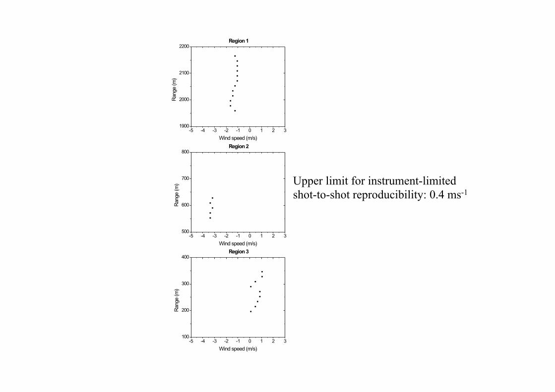
Upper limit for instrument-limited shot-to-shot reproducibility: 0.4 ms-1
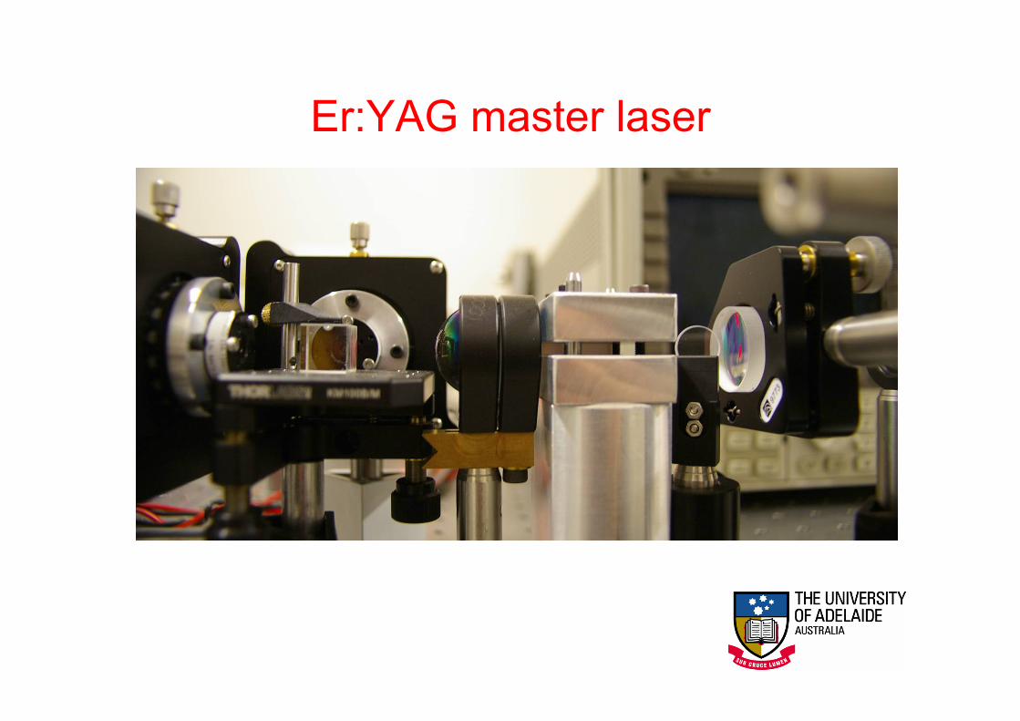
Er:YAG master laser
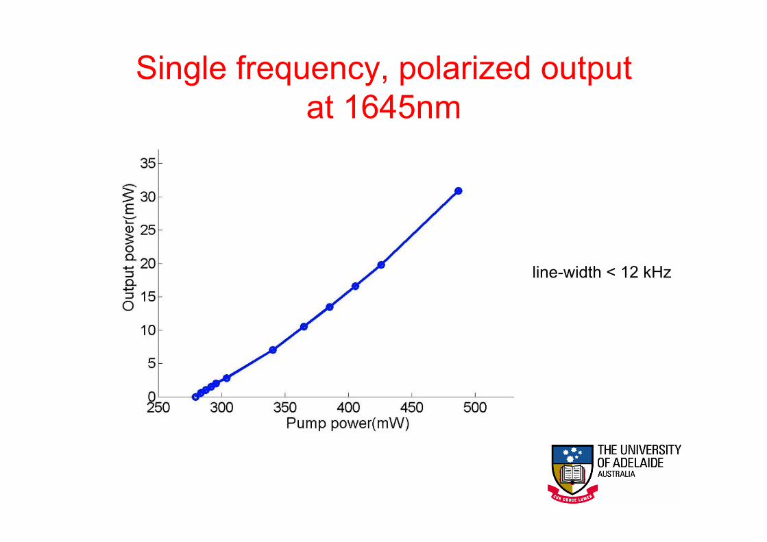
line-width < 12 kHz
Single frequency, polarized output at 1645nm
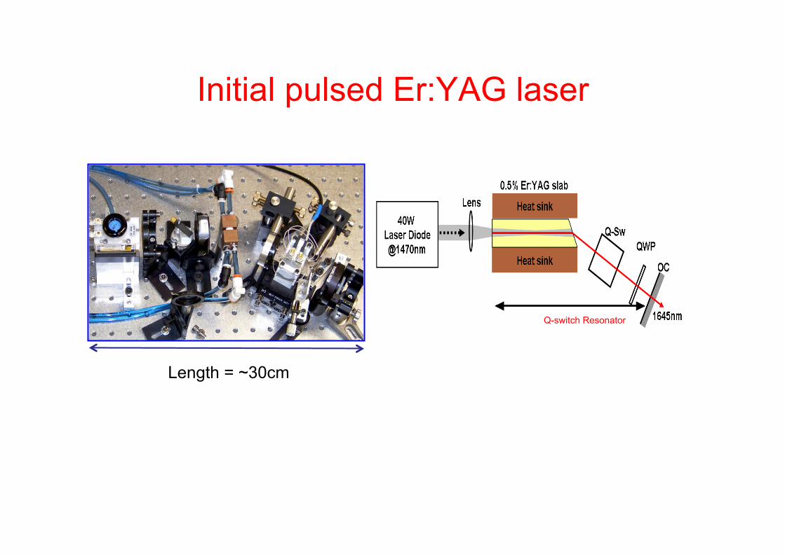
Q-switch Resonator
Length = ~30cm
Initial pulsed Er:YAG laser
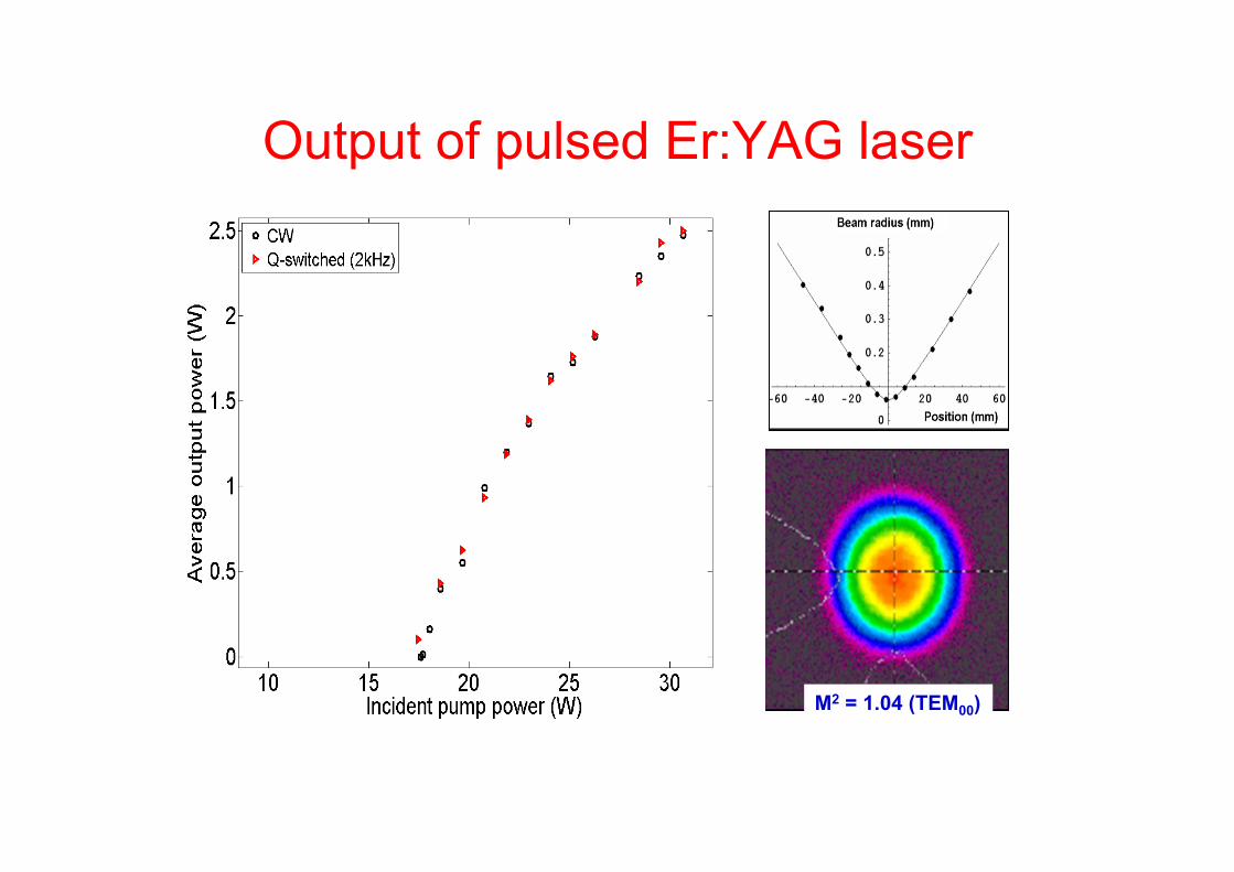
M2 = 1.04 (TEM00)
Output of pulsed Er:YAG laser
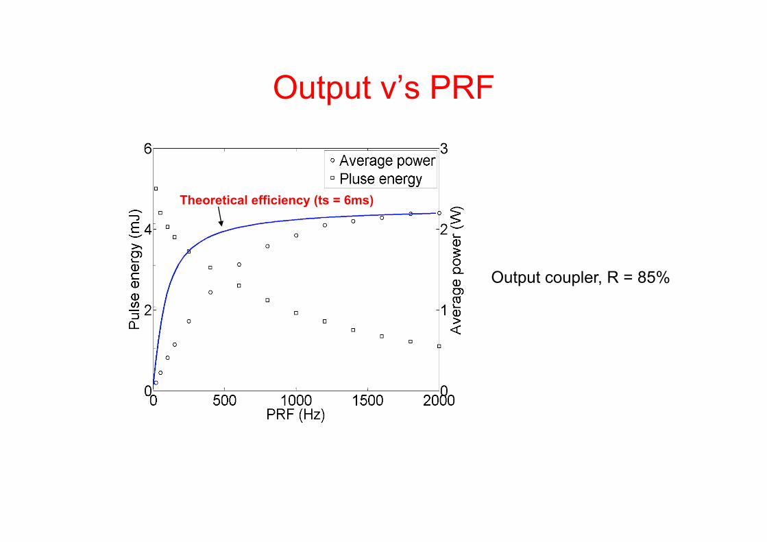
Theoretical efficiency (ts = 6ms)
Output coupler, R = 85%
Output v’s PRF
• Change gain medium to end-pumped CPFS gain • Use cheaper FAC 1470 nm pump diodes • Increase output to 10-20 mJ @ 1 kHz PRF • Incorporate in static (then scanning) coherent lidar system
Next for Coherent Lidar?
Low-cost water-vapour DIAL
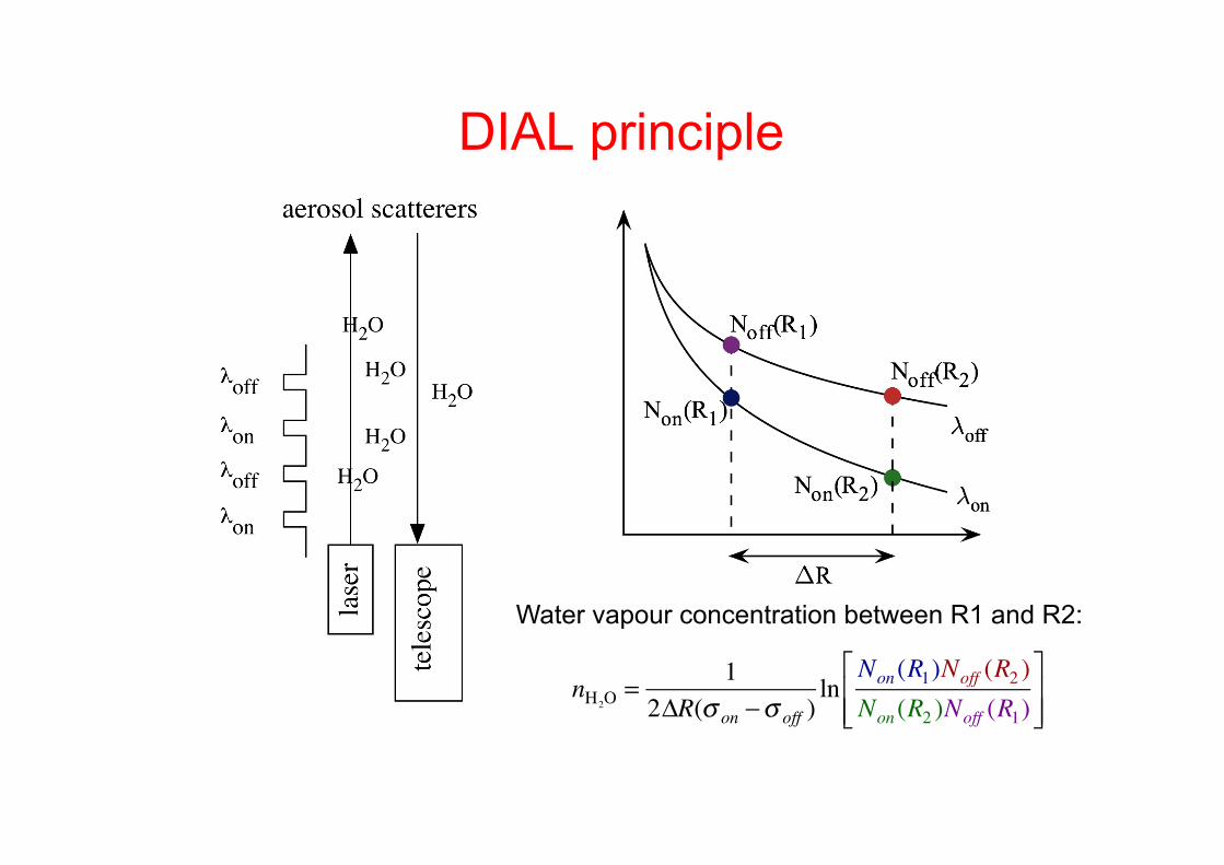
DIAL principle
nH2O = 12!R(" on #" off )
lnNon (R1)Noff (R2 )Non (R2 )Noff (R1)
$
%&&
'
())
Water vapour concentration between R1 and R2:
Low cost DIAL - laser considerations Diode laser is only really low cost laser available, but need a semiconductor optical amplifier!
Choice of wavelength • 830 nm GaAs (mature technology) • Single mode limited to ~ 0.5 W (high power diode or optical
amplifier) – Implies single photon counting
• Detector technology well developed (PMT or Si PIN/APD)
Type of diode? • Use FP diode (for better or for worse) • DFB diode (NOAA, Machol et al.) • External cavity (MSU, see Nehrir et al. ISTP8 S13-P08)
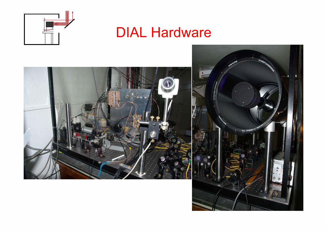
DIAL Hardware
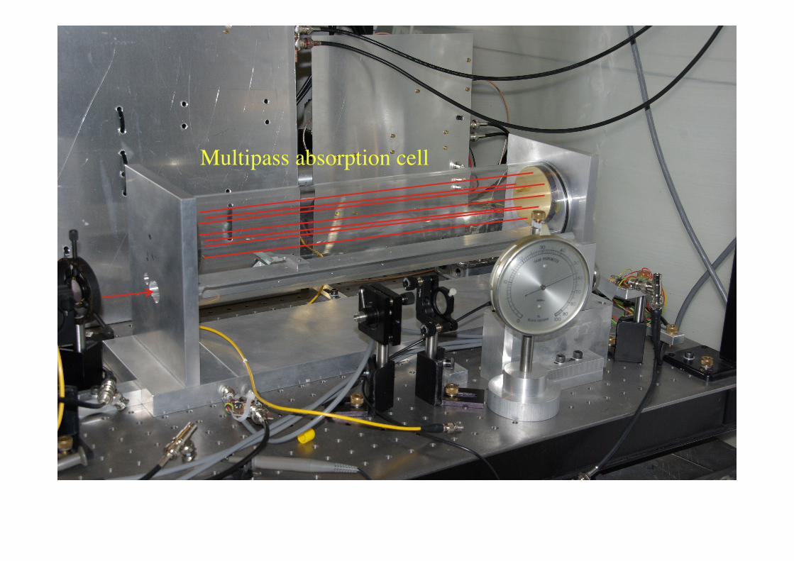
Multipass absorption cell
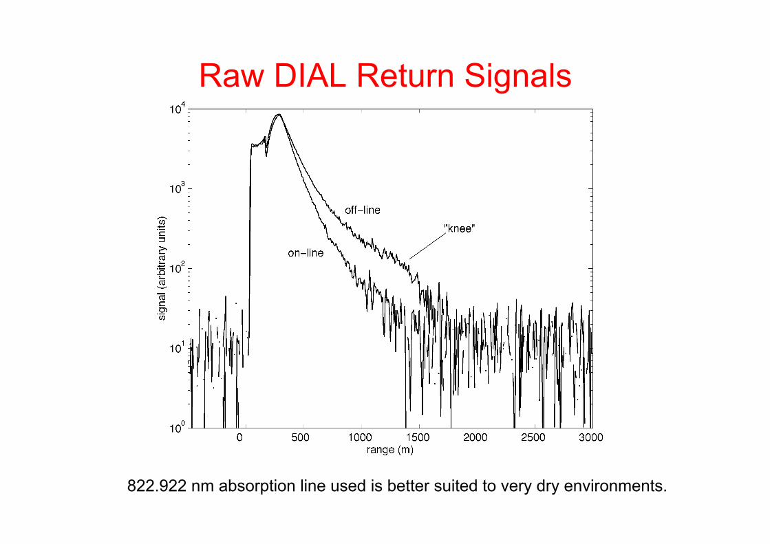
Raw DIAL Return Signals
822.922 nm absorption line used is better suited to very dry environments.
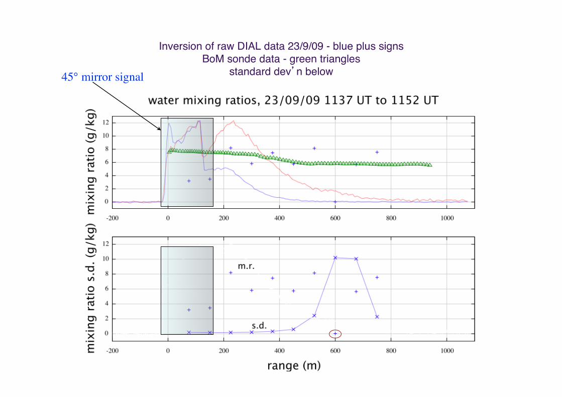
Inversion of raw DIAL data 23/9/09 - blue plus signsBoM sonde data - green triangles
standard dev’n below #45° mirror signal
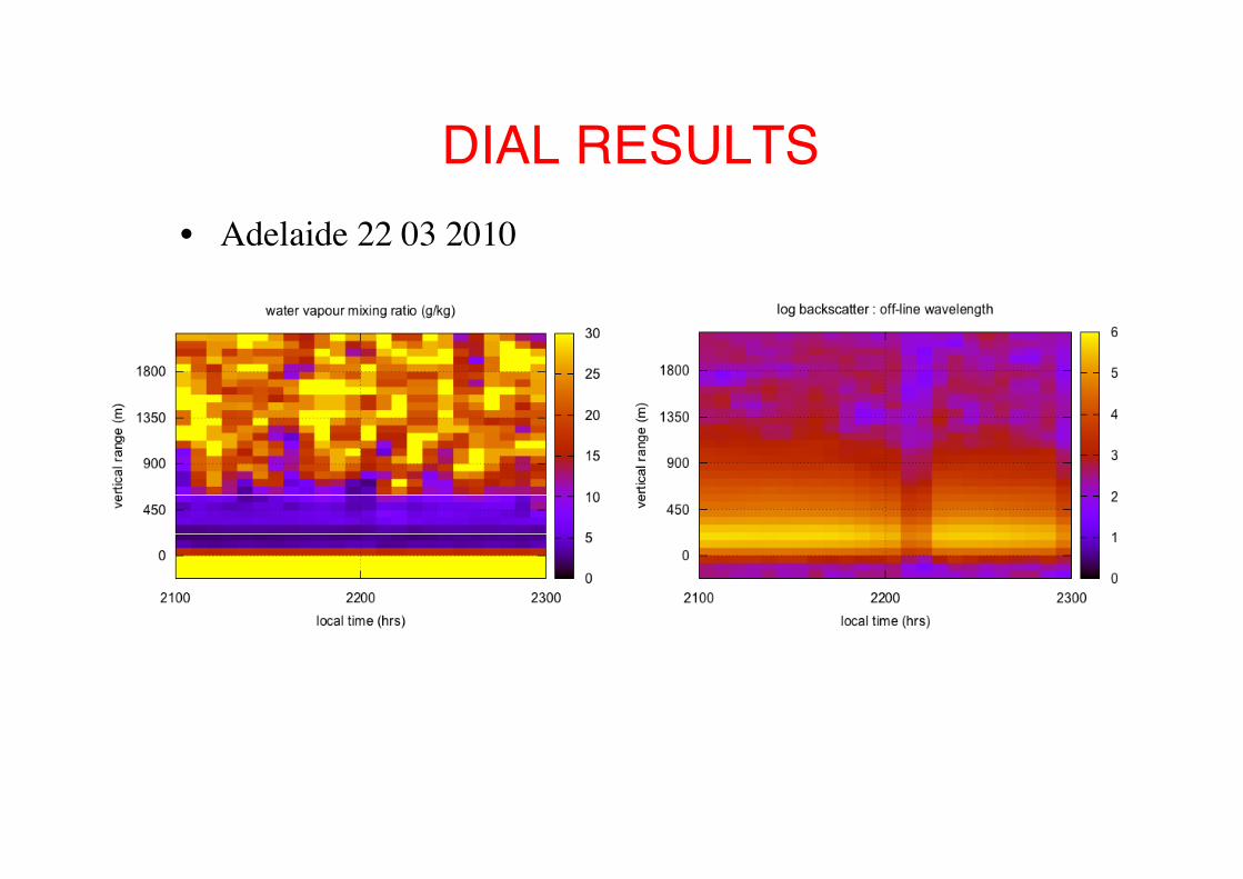
DIAL RESULTS#• Adelaide 22 03 2010
Next? • Use weaker absorption line
– 822.922 nm better suited to very dry environments • Receiver efficiency needs work • Better control of ASE to improve spectral purity • Background city light is a major limitation to range
- reduce receiver FoV?
• And after that – DFB diode technology? – Engineer for the field? – Try operation further inland? – Long-range system using higher power lasers?

Rayleigh/Raman Lidar

System schematic
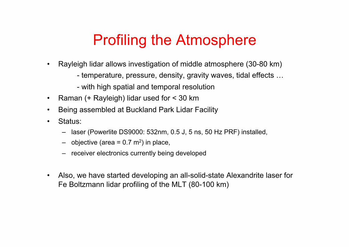
Profiling the Atmosphere • Rayleigh lidar allows investigation of middle atmosphere (30-80 km)
- temperature, pressure, density, gravity waves, tidal effects … - with high spatial and temporal resolution
• Raman (+ Rayleigh) lidar used for < 30 km • Being assembled at Buckland Park Lidar Facility • Status:
– laser (Powerlite DS9000: 532nm, 0.5 J, 5 ns, 50 Hz PRF) installed, – objective (area = 0.7 m2) in place, – receiver electronics currently being developed
• Also, we have started developing an all-solid-state Alexandrite laser for Fe Boltzmann lidar profiling of the MLT (80-100 km)
Na Guide-Star Laser
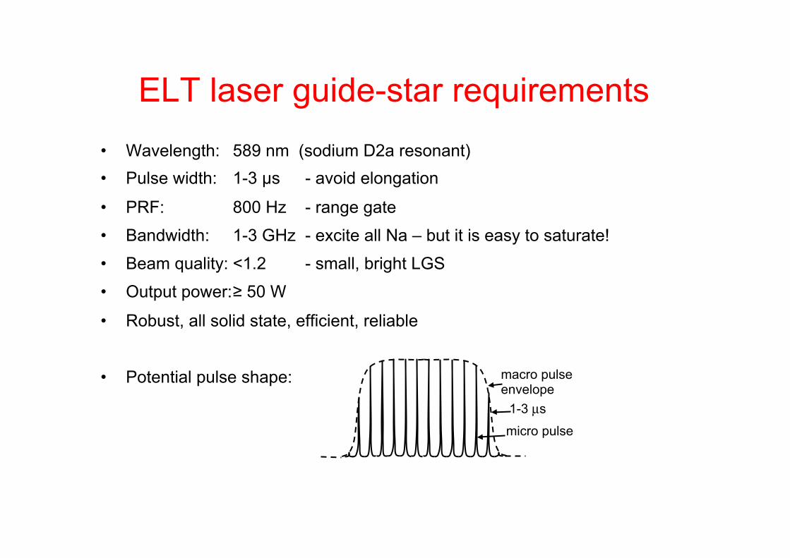
ELT laser guide-star requirements • Wavelength: 589 nm (sodium D2a resonant) • Pulse width: 1-3 µs - avoid elongation
• PRF: 800 Hz - range gate
• Bandwidth: 1-3 GHz - excite all Na – but it is easy to saturate!
• Beam quality: <1.2 - small, bright LGS
• Output power: ≥ 50 W
• Robust, all solid state, efficient, reliable
• Potential pulse shape:
micro pulse
macro pulse envelope
1-3 µs
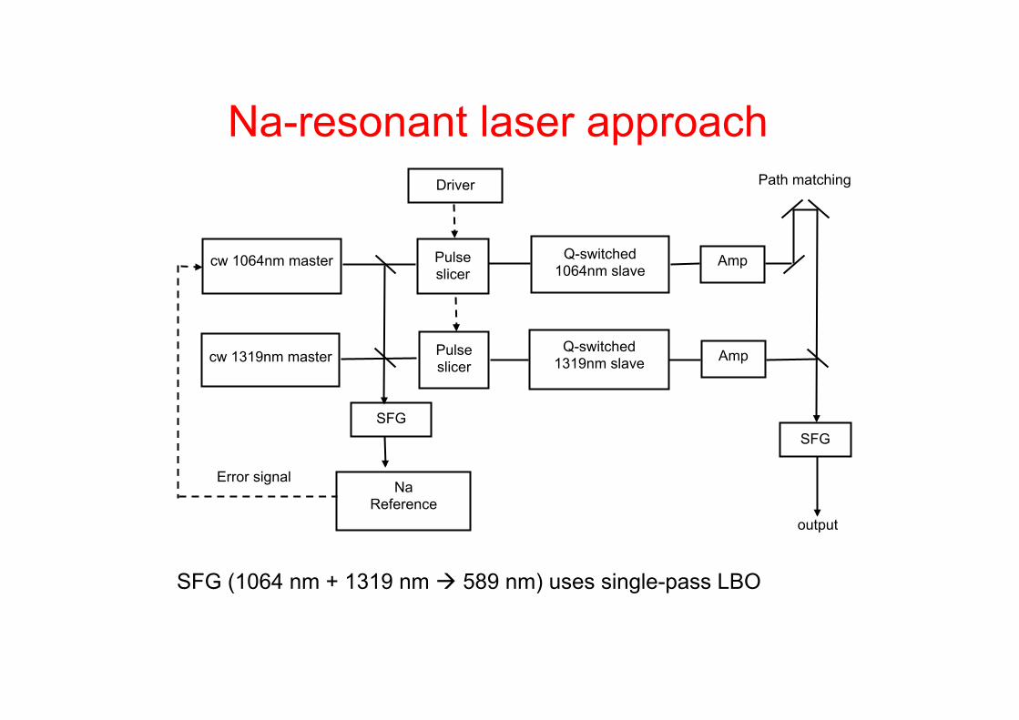
Na-resonant laser approach
SFG
cw 1064nm master
cw 1319nm master
Driver
Pulse slicer
Pulse slicer
Na Reference
Error signal
Q-switched 1064nm slave
Q-switched 1319nm slave
SFG
output
Path matching
SFG (1064 nm + 1319 nm à 589 nm) uses single-pass LBO
Amp
Amp

Injection mode-locking <3 µs
cw laser Pulse slicer
Q-Switched slave laser
1 ns
• Slice narrow pulse from output of narrow line-width cw master laser • Inject pulse into slave laser • Pulse seeds multiple longitudinal modes • Q-switch laser • Output: train of mode-locked pulses under Q-switched envelope - a “macro-micro” pulse burst
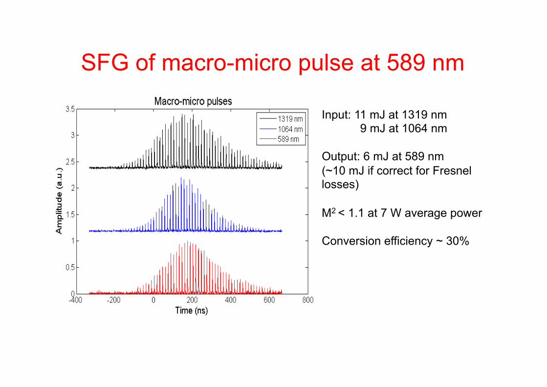
SFG of macro-micro pulse at 589 nm
Input: 11 mJ at 1319 nm 9 mJ at 1064 nm
Output: 6 mJ at 589 nm (~10 mJ if correct for Fresnel losses) M2 < 1.1 at 7 W average power Conversion efficiency ~ 30%