Embed Size (px)
Citation preview
Chapter 1
FORMS OF CORROSION
1.1
This introductory section includes basic definitions related to chemical and elec-trochemical reactions in the forward (f) and reverse (r) directions. The wordCorrosion stands for material or metal deterioration or surface damage in anaggressive environment. Corrosion is a chemical or electrochemical oxidationprocess, in which the metal transfers electrons to the environment and under-goes a valence change from zero to a positive value The environment maybe a liquid, gas or hybrid soil-liquid. These environments are called electrolytessince they have their own conductivity for electron transfer.
An electrolyte is analogous to a conductive solution, which contains posi-tively and negatively charged ions called cations and anions, respectively. Anion is an atom that has lost or gained one or more outer electron (s) and carriesan electrical charge. Thus, the corrosion process which can be chemical in na-ture or electrochemical due to a current flow, requires at least two reactions thatmust occur in a particular corrosive environment. These reactions are classifiedas anodic and cathodic reactions and are defined below for a metal M immersedin sulfuric acid solution as an example. Hence, metal oxidation oc-curs through an anodic reaction and reduction is through a cathodic reactionas shown below
where M = Metal= Hydrogen cation
Z = Valence or oxidation state
= Metal cation= Sulfate anion
INTRODUCTION
2 CHAPTER 1. FORMS OF CORROSION
The interpretation of the above equations indicate that an anodic reaction,which is equivalent to what is known as oxidation, loses metal electrons andthe cathodic reaction accepts or gains electrons for reducing pertinent ions.Consequently, both anodic and cathodic reactions are coupled in a corrosionprocess. Adding eqs. (1.1a) and (1.1b) yields eq. (1.1c). Thus, REDOX (RED= reduction and OX = oxidation) is the resultant reaction equation, eq. (1.1c),and represents the overall reaction at equilibrium where the anodic and cathodicreaction rates are equal. Observe that the anodic reaction is also referred to asan oxidation reaction since it has lost electrons, which has been gained bythe cathodic reaction for producing sulfuric acid Thus, a cathodicreaction is equivalent to a reduction reaction. Furthermore, The arrows in eq.(1.1) indicate the reaction directions as written and they represent irreversiblereactions. On the other hand, a reversible reaction is represented with an equalsign. Thus, the metal reaction can proceed to the right for oxidation or to theleft for reduction as indicated by eq. (1.2)
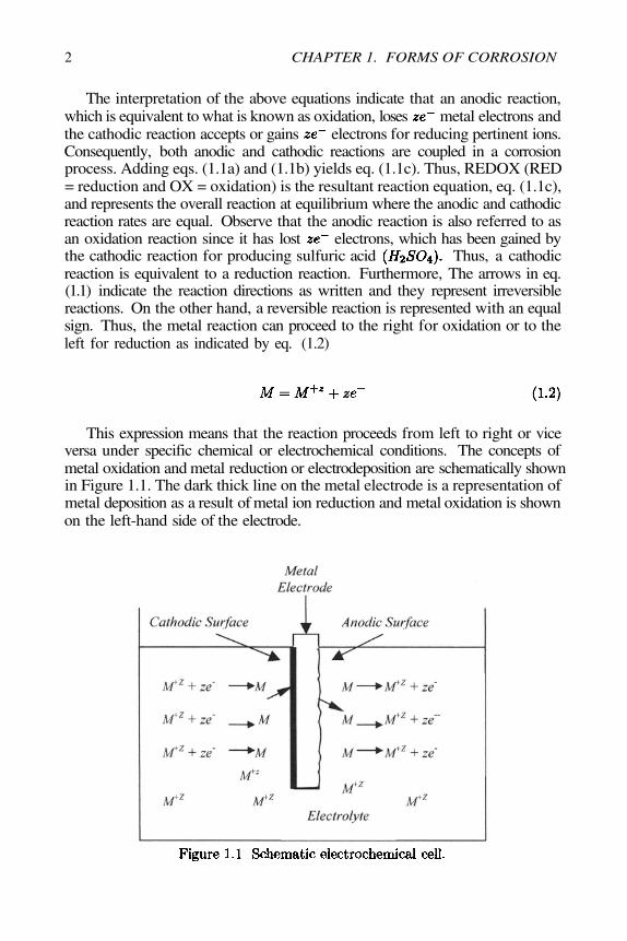
This expression means that the reaction proceeds from left to right or viceversa under specific chemical or electrochemical conditions. The concepts ofmetal oxidation and metal reduction or electrodeposition are schematically shownin Figure 1.1. The dark thick line on the metal electrode is a representation ofmetal deposition as a result of metal ion reduction and metal oxidation is shownon the left-hand side of the electrode.
1.2. CLASSIFICATION OF CORROSION 3
1.2 CLASSIFICATION OF CORROSION
There is not a unique classification of the types of corrosion, but the followingclassification is adapted hereafter.
1.2.1 GENERAL CORROSION
This is the case when the exposed metal/alloy surface area is entirely corrodedin an environment such as a liquid electrolyte (chemical solution, liquid metal),gaseous electrolyte (air, etc.), or a hybrid electrolyte (solid andwater, biological organisms, etc.). Some types of general corrosion and theirdescription are given below [8].
Atmospheric Corrosion on steel tanks, steel containers, parts, Alplates, etc..
Galvanic Corrosion between dissimilar metal/alloys or microstructuralphases (pearlitic steels, copper alloys, lead alloys).
High-Temperature Corrosion on carburized steels that forms a porousscale of several iron oxide phases.
Liquid-Metal Corrosion on stainless steel exposed to a sodium chlorideenvironment.
Molten-Salt Corrosion on stainless steels due to molten fluoridesetc.).
Biological Corrosion on steel, – alloys, – alloys in seawater.Stray-Current Corrosion on a pipeline near a railroad.
1.2.2 LOCALIZED CORROSION
This term implies that specific parts of an exposed surface area corrodes in asuitable electrolyte. This form of corrosion is more difficult to control thangeneral corrosion. Localized corrosion can be classified as [9]
Crevice Corrosion which is associated with a stagnant electrolyte suchas dirt, corrosion product, sand, etc. It occurs on a metal/alloy surface holes,underneath a gasket, lap joints under bolts, under rivet heads.
Filiform Corrosion is basically a special type of crevice corrosion, whichoccurs under a protective film. It is common on food and beverage cans beingexposed to the atmosphere.
Pitting Corrosion is an extremely localized corrosion mechanism thatcauses destructive pits.
Oral Corrosion occurs on dental alloys exposed to saliva.Biological Corrosion due to fouling organisms non-uniformly adhered on
steel in marine environments.Selective Leaching Corrosion is a metal removal process from the base
alloy matrix, such as dezincification ( is removed) in alloys andgraphitization (Fe is removed) in cast irons.
4
1.3 ATMOSPHERIC CORROSION
This is a uniform and general attack, in which the entire metal surface areaexposed to the corrosive environment is converted into its oxide form, providedthat the metallic material has a uniform microstructure.
Aqueous corrosion of iron (Fe) in solution and of in dilutedsolution are examples of uniform attack since Fe and can dissolve
(oxidize) at a uniform rate according to the following anodic and cathodic re-actions, respectively.
where is hydrogen gas. The cathodic reaction is the common hydrogenevolution process. In fact, the aggressiveness of a solution to cause a metal tooxidize can be altered by additions of water, which is an amphotetic compoundbecause it can act as an acid or base due to its dissociation as indicated below
Atmospheric corrosion of a steel structure is also a common example ofuniform corrosion, which is manifested as a brown-color corrosion layer on theexposed steel surface. This layer is a ferric hydroxide compound known as Rust.The formation of Brown Rust is as follows
where = Multiplying factor for balancing the number of electrons= Ferrous hydroxide (unstable compound)= Ferric hydroxide (with cations)
= Hydrated Ferric hydroxide=The compound precipitates as a solid
CHAPTER 1. FORMS OF CORROSION
1.3. ATMOSPHERIC CORROSION 5
In addition, can uniformly corrode forming a White Rust according tothe following reactions [1-3,12]
In fact, the compound or is zinc car-bonate or white rust or wet-storage stain (porous). Atmospheric corrosion ofaluminum is due to a passive oxide film formation instead of a porous layer.The gray/black-color film may form as follows
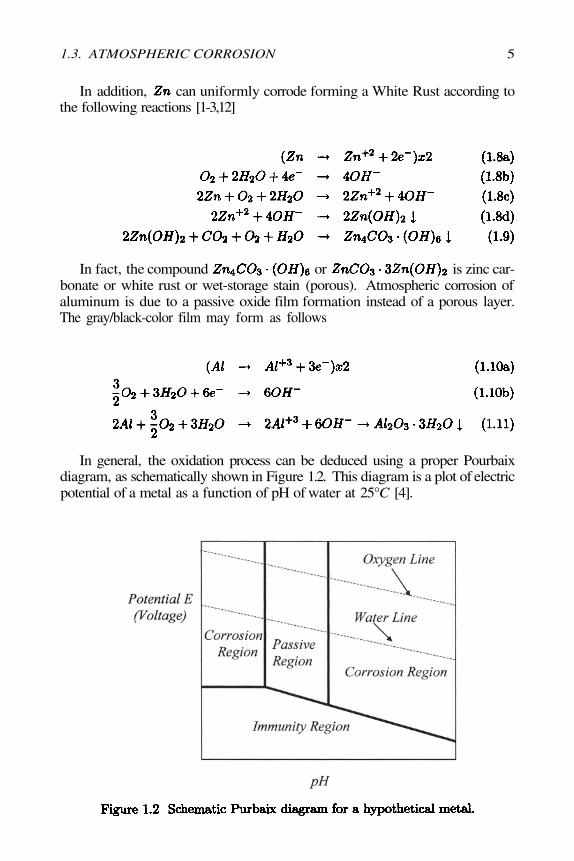
In general, the oxidation process can be deduced using a proper Pourbaixdiagram, as schematically shown in Figure 1.2. This diagram is a plot of electricpotential of a metal as a function of pH of water at 25°C [4].
6
This type of diagram indicates the possible electrochemical process on ametal surface if the potential and the pH of the electrochemical systems areknown or estimated. In fact, corrosion rates can not be determined from aPourbaix diagrams. The diagram includes regions identified as corrosion wherea metal oxidizes, passive region where a metal is protected by a stable oxide filmbeing adhered on the metal surface, and immunity where corrosion or passivationare suppressed.
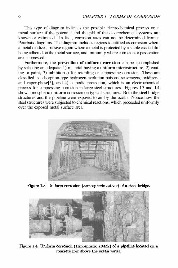
Furthermore, the prevention of uniform corrosion can be accomplishedby selecting an adequate 1) material having a uniform microstructure, 2) coat-ing or paint, 3) inhibitor(s) for retarding or suppressing corrosion. These areclassified as adsorption-type hydrogen-evolution poisons, scavengers, oxidizers,and vapor-phase[5], and 4) cathodic protection, which is an electrochemicalprocess for suppressing corrosion in large steel structures. Figures 1.3 and 1.4show atmospheric uniform corrosion on typical structures. Both the steel bridgestructures and the pipeline were exposed to air by the ocean. Notice how thesteel structures were subjected to chemical reactions, which proceeded uniformlyover the exposed metal surface area.
CHAPTER 1. FORMS OF CORROSION
1.4. GALVANIC CORROSION 7
1.4 GALVANIC CORROSION
Galvanic corrosion is either a chemical or an electrochemical corrosion. Thelatter is due to a potential difference between two different metals connectedthrough a circuit for current flow to occur from more active metal (more negativepotential) to the more noble metal (more positive potential).
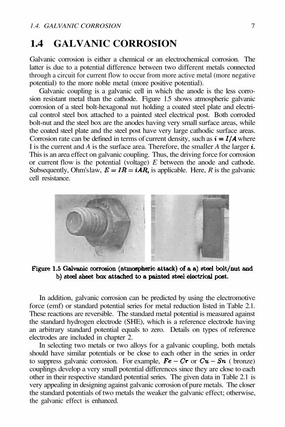
Galvanic coupling is a galvanic cell in which the anode is the less corro-sion resistant metal than the cathode. Figure 1.5 shows atmospheric galvaniccorrosion of a steel bolt-hexagonal nut holding a coated steel plate and electri-cal control steel box attached to a painted steel electrical post. Both corrodedbolt-nut and the steel box are the anodes having very small surface areas, whilethe coated steel plate and the steel post have very large cathodic surface areas.Corrosion rate can be defined in terms of current density, such as whereI is the current and A is the surface area. Therefore, the smaller A the largerThis is an area effect on galvanic coupling. Thus, the driving force for corrosionor current flow is the potential (voltage) E between the anode and cathode.Subsequently, Ohm's law, is applicable. Here, R is the galvaniccell resistance.
In addition, galvanic corrosion can be predicted by using the electromotiveforce (emf) or standard potential series for metal reduction listed in Table 2.1.These reactions are reversible. The standard metal potential is measured againstthe standard hydrogen electrode (SHE), which is a reference electrode havingan arbitrary standard potential equals to zero. Details on types of referenceelectrodes are included in chapter 2.
In selecting two metals or two alloys for a galvanic coupling, both metalsshould have similar potentials or be close to each other in the series in orderto suppress galvanic corrosion. For example, or ( bronze)couplings develop a very small potential differences since they are close to eachother in their respective standard potential series. The given data in Table 2.1 isvery appealing in designing against galvanic corrosion of pure metals. The closerthe standard potentials of two metals the weaker the galvanic effect; otherwise,the galvanic effect is enhanced.
8
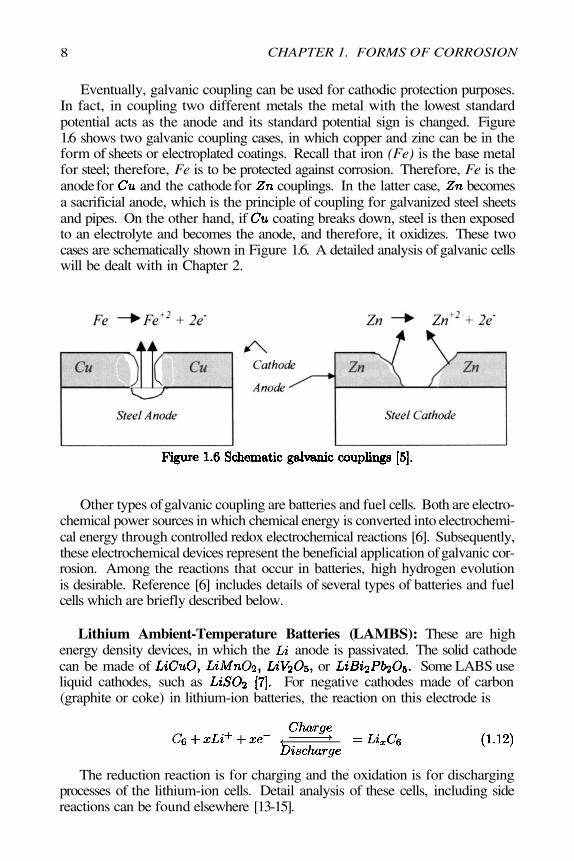
Eventually, galvanic coupling can be used for cathodic protection purposes.In fact, in coupling two different metals the metal with the lowest standardpotential acts as the anode and its standard potential sign is changed. Figure1.6 shows two galvanic coupling cases, in which copper and zinc can be in theform of sheets or electroplated coatings. Recall that iron (Fe) is the base metalfor steel; therefore, Fe is to be protected against corrosion. Therefore, Fe is theanode for and the cathode for couplings. In the latter case, becomesa sacrificial anode, which is the principle of coupling for galvanized steel sheetsand pipes. On the other hand, if coating breaks down, steel is then exposedto an electrolyte and becomes the anode, and therefore, it oxidizes. These twocases are schematically shown in Figure 1.6. A detailed analysis of galvanic cellswill be dealt with in Chapter 2.
Other types of galvanic coupling are batteries and fuel cells. Both are electro-chemical power sources in which chemical energy is converted into electrochemi-cal energy through controlled redox electrochemical reactions [6]. Subsequently,these electrochemical devices represent the beneficial application of galvanic cor-rosion. Among the reactions that occur in batteries, high hydrogen evolutionis desirable. Reference [6] includes details of several types of batteries and fuelcells which are briefly described below.
Lithium Ambient-Temperature Batteries (LAMBS): These are highenergy density devices, in which the anode is passivated. The solid cathodecan be made of or Some LABS useliquid cathodes, such as For negative cathodes made of carbon(graphite or coke) in lithium-ion batteries, the reaction on this electrode is
The reduction reaction is for charging and the oxidation is for dischargingprocesses of the lithium-ion cells. Detail analysis of these cells, including sidereactions can be found elsewhere [13-15].
CHAPTER 1. FORMS OF CORROSION
1.4. GALVANIC CORROSION 9
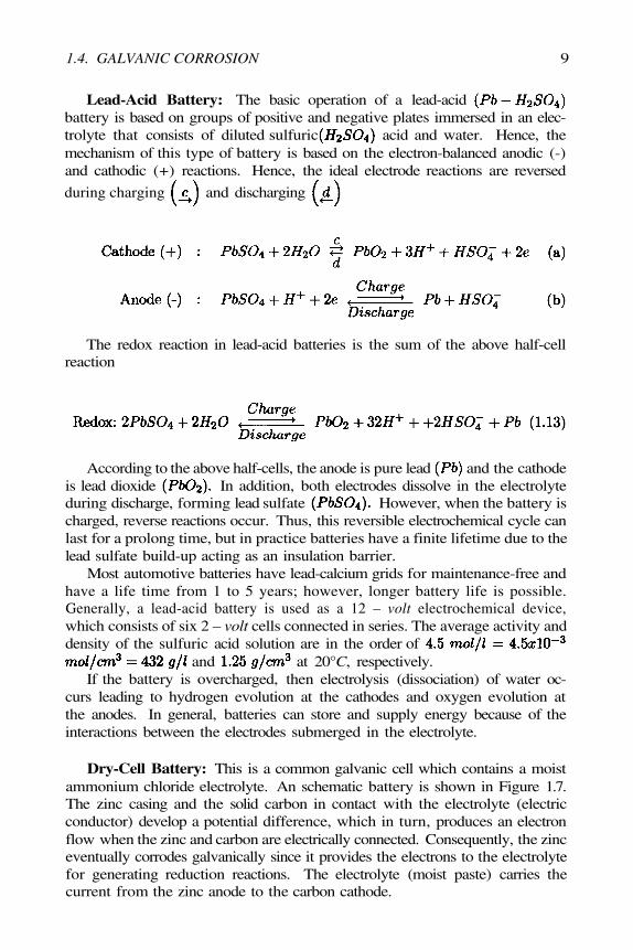
Lead-Acid Battery: The basic operation of a lead-acidbattery is based on groups of positive and negative plates immersed in an elec-trolyte that consists of diluted sulfuric acid and water. Hence, themechanism of this type of battery is based on the electron-balanced anodic (-)and cathodic (+) reactions. Hence, the ideal electrode reactions are reversed
during charging and discharging
The redox reaction in lead-acid batteries is the sum of the above half-cellreaction
According to the above half-cells, the anode is pure lead and the cathodeis lead dioxide In addition, both electrodes dissolve in the electrolyteduring discharge, forming lead sulfate However, when the battery ischarged, reverse reactions occur. Thus, this reversible electrochemical cycle canlast for a prolong time, but in practice batteries have a finite lifetime due to thelead sulfate build-up acting as an insulation barrier.
Most automotive batteries have lead-calcium grids for maintenance-free andhave a life time from 1 to 5 years; however, longer battery life is possible.Generally, a lead-acid battery is used as a 12 – volt electrochemical device,which consists of six 2 – volt cells connected in series. The average activity anddensity of the sulfuric acid solution are in the order of
and at 20°C, respectively.If the battery is overcharged, then electrolysis (dissociation) of water oc-
curs leading to hydrogen evolution at the cathodes and oxygen evolution atthe anodes. In general, batteries can store and supply energy because of theinteractions between the electrodes submerged in the electrolyte.
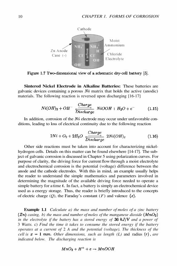
Dry-Cell Battery: This is a common galvanic cell which contains a moistammonium chloride electrolyte. An schematic battery is shown in Figure 1.7.The zinc casing and the solid carbon in contact with the electrolyte (electricconductor) develop a potential difference, which in turn, produces an electronflow when the zinc and carbon are electrically connected. Consequently, the zinceventually corrodes galvanically since it provides the electrons to the electrolytefor generating reduction reactions. The electrolyte (moist paste) carries thecurrent from the zinc anode to the carbon cathode.
10
Sintered Nickel Electrode in Alkaline Batteries: These batteries aregalvanic devices containing a porous matrix that holds the active (anodic)materials. The following reaction is reversed upon discharging [16-17]
In addition, corrosion of the electrode may occur under unfavorable con-ditions, leading to loss of electrical continuity due to the following reaction
Other side reactions must be taken into account for characterizing nickel-hydrogen cells. Details on this matter can be found elsewhere [14-17]. The sub-ject of galvanic corrosion is discussed in Chapter 5 using polarization curves. Forpurpose of clarity, the driving force for current flow through a moist electrolyteand electrochemical corrosion is the potential (voltage) difference between theanode and the cathode electrodes. With this in mind, an example usually helpsthe reader to understand the simple mathematics and parameters involved indetermining the magnitude of the available driving force needed to operate asimple battery for a time In fact, a battery is simply an electrochemical deviceused as a energy storage. Thus, the reader is briefly introduced to the conceptsof electric charge (Q), the Faraday’s constant (F) and valence
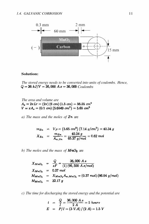
Example 1.1 Calculate a) the mass and number of moles of a zinc batterycasing, b) the mass and number of moles of the manganese dioxide
in the electrolyte if the battery has a stored energy of and a power of3 Watts. c) Find the time it takes to consume the stored energy if the batteryoperates at a current of 2 A and the potential (voltage). The thickness of thecell is Other dimensions, such as length (L) and radius areindicated below. The discharging reaction is
CHAPTER 1. FORMS OF CORROSION
1.4. GALVANIC CORROSION 11
Solution:
The stored energy needs to be converted into units of coulombs. Hence,Coulombs
The area and volume are
a) The mass and the moles of are
b) The moles and the mass of are
c) The time for discharging the stored energy and the potential are
12
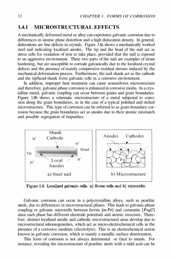
1.4.1 MICROSTRUCTURAL EFFECTSA mechanically deformed metal or alloy can experience galvanic corrosion due todifferences in atomic plane distortion and a high dislocation density. In general,dislocations are line defects in crystals. Figure 1.8a shows a mechanically workedsteel nail indicating localized anodes. The tip and the head of the nail act asstress cells for oxidation of iron to take place, provided that the nail is exposedto an aggressive environment. These two parts of the nail are examples of strainhardening, but are susceptible to corrode galvanically due to the localized crystaldefects and the presence of mainly compressive residual stresses induced by themechanical deformation process. Furthermore, the nail shank act as the cathodeand the tip/head-shank form galvanic cells in a corrosive environment.
In addition, improper heat treatment can cause nonuniform microstructureand therefore, galvanic-phase corrosion is enhanced in corrosive media. In a crys-talline metal, galvanic coupling can occur between grains and grain boundaries.Figure 1.8b shows a schematic microstructure of a metal subjected to corro-sion along the grain boundaries, as in the case of a typical polished and etchedmicrostructure. This type of corrosion can be referred to as grain-boundary cor-rosion because the grain boundaries act as anodes due to their atomic mismatchand possible segregation of impurities.
Galvanic corrosion can occur in a polycrystalline alloys, such as pearliticsteels, due to differences in microstructural phases. This leads to galvanic-phasecoupling or galvanic microcells between ferrite and cementitesince each phase has different electrode potentials and atomic structure. There-fore, distinct localized anodic and cathodic microstructural areas develop due tomicrostructural inhomogeneities, which act as micro-electrochemical cells in thepresence of a corrosive medium (electrolyte). This is an electrochemical actionknown as galvanic corrosion, which is mainly a metallic surface deterioration.
This form of corrosion is not always detrimental or fatal to metals. Forinstance, revealing the microstructure of pearlitic steels with a mild acid can be
CHAPTER 1. FORMS OF CORROSION
1.4. GALVANIC CORROSION 13
accomplished due to the formation of galvanic microcells. In this case, pearliteconsists of ferrite and cementite and when it is etched with a mild acid, whichis the electrolyte, galvanic microcells between ferrite (cathode) and cementite(anode) are generated. Consequently, pearlite is revealed as dark cementite andwhite ferrite.
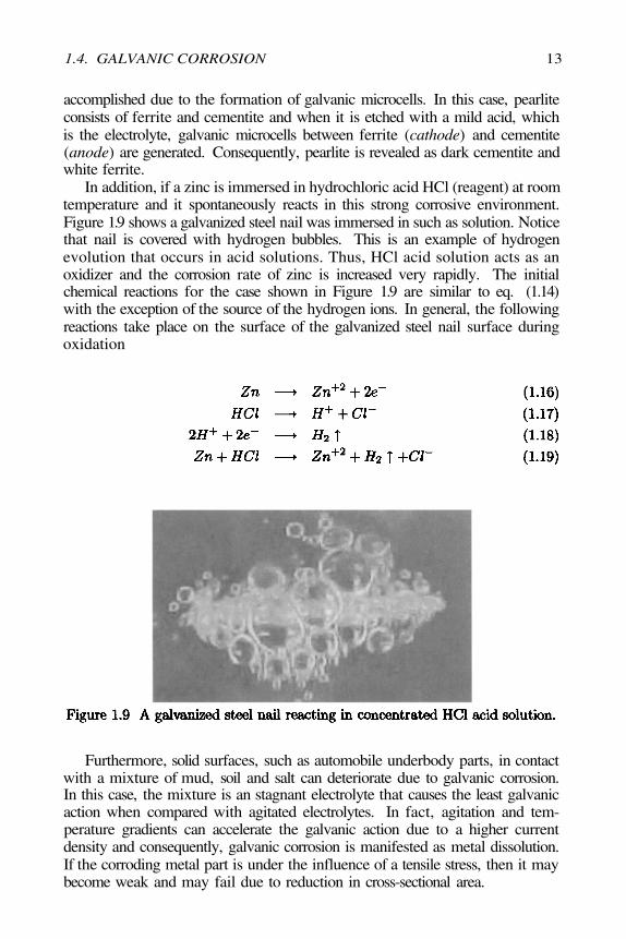
In addition, if a zinc is immersed in hydrochloric acid HCl (reagent) at roomtemperature and it spontaneously reacts in this strong corrosive environment.Figure 1.9 shows a galvanized steel nail was immersed in such as solution. Noticethat nail is covered with hydrogen bubbles. This is an example of hydrogenevolution that occurs in acid solutions. Thus, HCl acid solution acts as anoxidizer and the corrosion rate of zinc is increased very rapidly. The initialchemical reactions for the case shown in Figure 1.9 are similar to eq. (1.14)with the exception of the source of the hydrogen ions. In general, the followingreactions take place on the surface of the galvanized steel nail surface duringoxidation
Furthermore, solid surfaces, such as automobile underbody parts, in contactwith a mixture of mud, soil and salt can deteriorate due to galvanic corrosion.In this case, the mixture is an stagnant electrolyte that causes the least galvanicaction when compared with agitated electrolytes. In fact, agitation and tem-perature gradients can accelerate the galvanic action due to a higher currentdensity and consequently, galvanic corrosion is manifested as metal dissolution.If the corroding metal part is under the influence of a tensile stress, then it maybecome weak and may fail due to reduction in cross-sectional area.
14
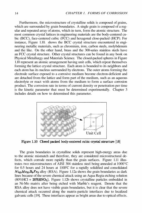
Furthermore, the microstructure of crystalline solids is composed of grains,which are surrounded by grain boundaries. A single grain is composed of a reg-ular and repeated array of atoms, which in turn, form the atomic structure. Themost common crystal lattices in engineering materials are the body-centered cu-bic (BCC), face-centered cubic (FCC) and hexagonal close-packed (HCP). Forinstance, Figure 1.10. shows the BCC crystal structure encountered in engi-neering metallic materials, such as chromium, iron, carbon steels, molybdenumand the like. On the other hand, brass and the 300-series stainless steels havean FCC crystal structure. Other crystal structures can be found in any book onPhysical Metallurgy and Materials Science. The closed-packed spheres in Figure1.10 represent an atomic arrangement having unit cells, which repeat themselvesforming the lattice crystal structure. Each atom is bounded to its neighbors andeach atom has its nucleus surrounded by electrons. The outer atoms forming theelectrode surface exposed to a corrosive medium become electron-deficient andare detached from the lattice and form part of the medium, such as an aqueouselectrolyte or react with atoms from the medium to form a surface corrosionproduct. The corrosion rate in terms of current density or penetration per timeis the kinetic parameter that must be determined experimentally. Chapter 3includes details on how to determined this parameter.
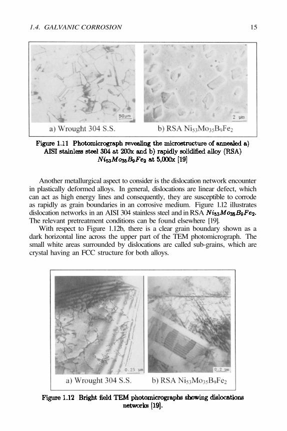
The grain boundaries in crystalline solids represent high-energy areas dueto the atomic mismatch and therefore, they are considered microstructural de-fects, which corrode more rapidly than the grain surfaces. Figure 1.11 illus-trates two microstructures of AISI 304 stainless steel being annealed at 1000°Cfor 0.5 hours and 24 hours at 1100°C for a rapidly solidified and consolidated
alloy (RSA). Figure 1.12a shows the grain boundaries as darklines because of the severe chemical attack using an Aqua Regia etching solution(80%HCl + Figure 1.12b shows crystalline particles embedded inan Ni-Mo matrix after being etched with Marble’s reagent. Denote that theRSA alloy does not have visible grain boundaries, but it is clear that the severechemical attack occurred along the matrix-particle interfaces due to localizedgalvanic cells [19]. These interfaces appear as bright areas due to optical effects.
CHAPTER 1. FORMS OF CORROSION
1.4. GALVANIC CORROSION 15
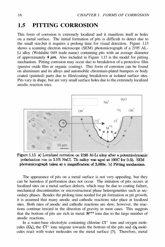
Another metallurgical aspect to consider is the dislocation network encounterin plastically deformed alloys. In general, dislocations are linear defect, whichcan act as high energy lines and consequently, they are susceptible to corrodeas rapidly as grain boundaries in an corrosive medium. Figure 1.12 illustratesdislocation networks in an AISI 304 stainless steel and in RSAThe relevant pretreatment conditions can be found elsewhere [19].
With respect to Figure 1.12b, there is a clear grain boundary shown as adark horizontal line across the upper part of the TEM photomicrograph. Thesmall white areas surrounded by dislocations are called sub-grains, which arecrystal having an FCC structure for both alloys.
16
1.5 PITTING CORROSION
This form of corrosion is extremely localized and it manifests itself as holeson a metal surface. The initial formation of pits is difficult to detect due tothe small size,but it requires a prolong time for visual detection. Figure 1.13shows a scanning electron microscope (SEM) photomicrograph of a 2195 AL-Li alloy (Weldalite 049 trade name) containing pits with an average diameterof approximately Also included in Figure 1.13 is the model for pittingmechanism. Pitting corrosion may occur due to breakdown of a protective film(passive oxide film or organic coating). This form of corrosion can be foundon aluminum and its alloys and automobile chromium-plated bumpers or bodycoated (painted) parts due to film/coating breakdown at isolated surface sites.Pits vary in shape, but are very small surface holes due to the extremely localizedanodic reaction sites.
The appearance of pits on a metal surface is not very appealing, but theycan be harmless if perforation does not occur. The initiation of pits occurs atlocalized sites on a metal surface defects, which may be due to coating failure,mechanical discontinuities or microstructural phase heterogeneities such as sec-ondary phases. Besides the prolong time needed for pit formation or pit growth,it is assumed that many anodic and cathodic reactions take place at localizedsites. Both rates of anodic and cathodic reactions are slow; however, the reac-tions continue inward in the direction of gravity in most cases. This suggeststhat the bottom of pits are rich in metal ions due to the large number ofanodic reactions.
In a water-base electrolyte containing chlorine ions and oxygen mole-cules the ions migrate towards the bottom of the pits and mole-cules react with water molecules on the metal surface [5]. Therefore, metal
CHAPTER 1. FORMS OF CORROSION
1.5. PITTING CORROSION 17
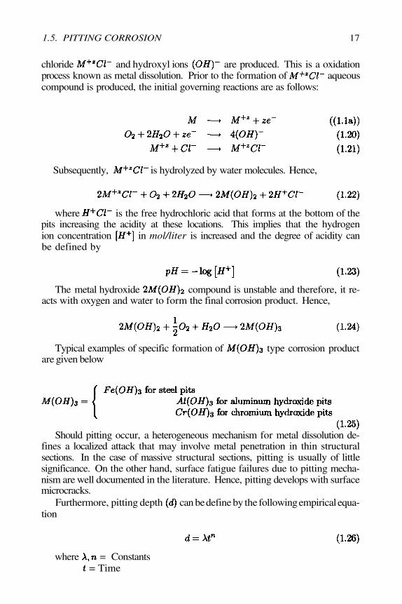
chloride and hydroxyl ions are produced. This is a oxidationprocess known as metal dissolution. Prior to the formation of aqueouscompound is produced, the initial governing reactions are as follows:
Subsequently, is hydrolyzed by water molecules. Hence,
where is the free hydrochloric acid that forms at the bottom of thepits increasing the acidity at these locations. This implies that the hydrogenion concentration in mol/liter is increased and the degree of acidity canbe defined by
The metal hydroxide compound is unstable and therefore, it re-acts with oxygen and water to form the final corrosion product. Hence,
Typical examples of specific formation of type corrosion productare given below
Should pitting occur, a heterogeneous mechanism for metal dissolution de-fines a localized attack that may involve metal penetration in thin structuralsections. In the case of massive structural sections, pitting is usually of littlesignificance. On the other hand, surface fatigue failures due to pitting mecha-nism are well documented in the literature. Hence, pitting develops with surfacemicrocracks.
Furthermore, pitting depth can be define by the following empirical equa-tion
where= Time
= Constants
18
1.6 CREVICE CORROSION
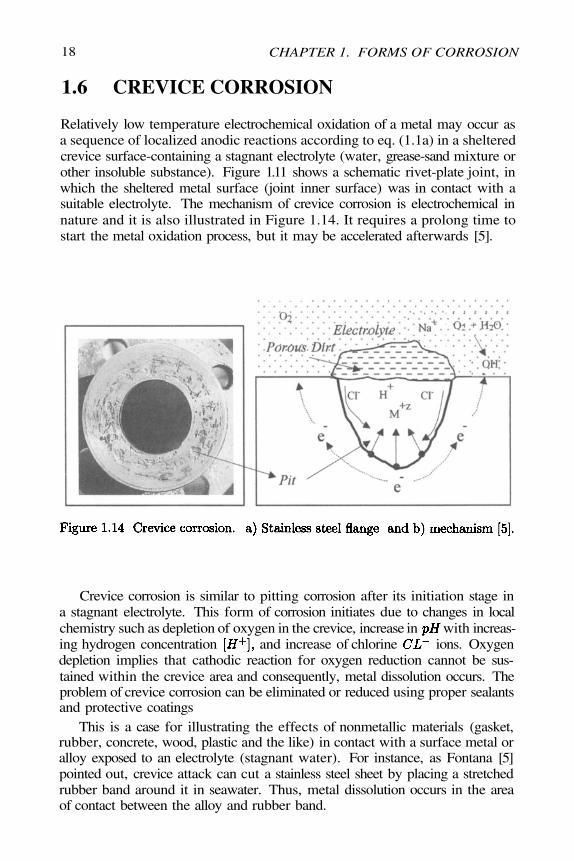
Relatively low temperature electrochemical oxidation of a metal may occur asa sequence of localized anodic reactions according to eq. (1.1a) in a shelteredcrevice surface-containing a stagnant electrolyte (water, grease-sand mixture orother insoluble substance). Figure 1.11 shows a schematic rivet-plate joint, inwhich the sheltered metal surface (joint inner surface) was in contact with asuitable electrolyte. The mechanism of crevice corrosion is electrochemical innature and it is also illustrated in Figure 1.14. It requires a prolong time tostart the metal oxidation process, but it may be accelerated afterwards [5].
Crevice corrosion is similar to pitting corrosion after its initiation stage ina stagnant electrolyte. This form of corrosion initiates due to changes in localchemistry such as depletion of oxygen in the crevice, increase in with increas-ing hydrogen concentration and increase of chlorine ions. Oxygendepletion implies that cathodic reaction for oxygen reduction cannot be sus-tained within the crevice area and consequently, metal dissolution occurs. Theproblem of crevice corrosion can be eliminated or reduced using proper sealantsand protective coatings
This is a case for illustrating the effects of nonmetallic materials (gasket,rubber, concrete, wood, plastic and the like) in contact with a surface metal oralloy exposed to an electrolyte (stagnant water). For instance, as Fontana [5]pointed out, crevice attack can cut a stainless steel sheet by placing a stretchedrubber band around it in seawater. Thus, metal dissolution occurs in the areaof contact between the alloy and rubber band.
CHAPTER 1. FORMS OF CORROSION
1.7. CORROSION-INDUCED SPALLING 19
1.7 CORROSION-INDUCED SPALLING
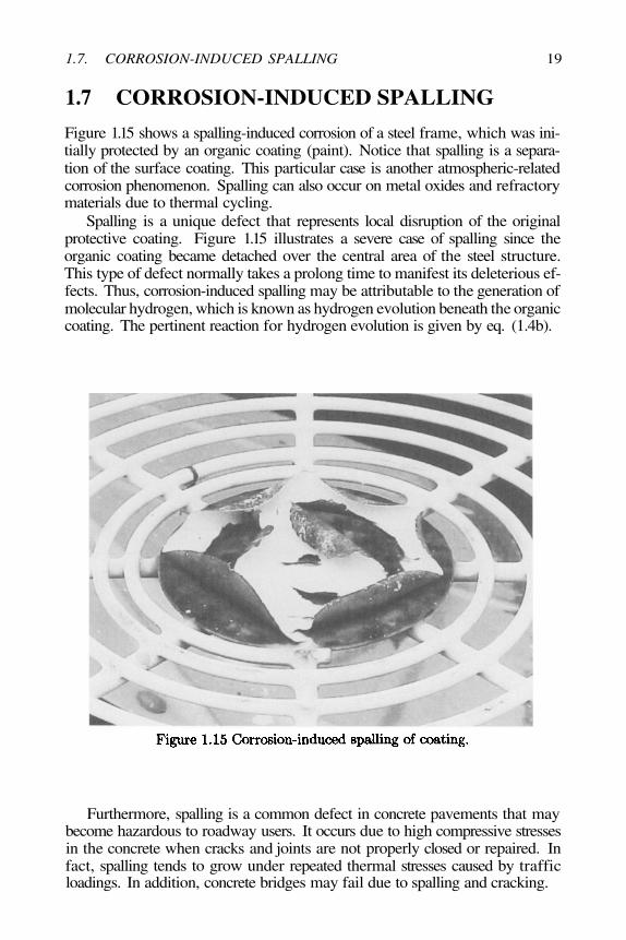
Figure 1.15 shows a spalling-induced corrosion of a steel frame, which was ini-tially protected by an organic coating (paint). Notice that spalling is a separa-tion of the surface coating. This particular case is another atmospheric-relatedcorrosion phenomenon. Spalling can also occur on metal oxides and refractorymaterials due to thermal cycling.
Spalling is a unique defect that represents local disruption of the originalprotective coating. Figure 1.15 illustrates a severe case of spalling since theorganic coating became detached over the central area of the steel structure.This type of defect normally takes a prolong time to manifest its deleterious ef-fects. Thus, corrosion-induced spalling may be attributable to the generation ofmolecular hydrogen, which is known as hydrogen evolution beneath the organiccoating. The pertinent reaction for hydrogen evolution is given by eq. (1.4b).
Furthermore, spalling is a common defect in concrete pavements that maybecome hazardous to roadway users. It occurs due to high compressive stressesin the concrete when cracks and joints are not properly closed or repaired. Infact, spalling tends to grow under repeated thermal stresses caused by trafficloadings. In addition, concrete bridges may fail due to spalling and cracking.
20
1.8 STRESS CORROSION CRACKING
Structural parts subjected to a combination of a tensile stress and a corrosiveenvironment may prematurely fail at a stress below the yield strength. This phe-nomenon is known as environmentally induced cracking (EIC), which is dividedinto the following categories: stress-corrosion cracking (SCC), hydrogen-inducedcracking (HIC) and corrosion-fatigue cracking (CFC). These three categoriescan develop under the influence of an applied potential related to polarizationdiagram. The former is extensively discussed in Chapter 3 and 4. The EIC phe-nomenon has been studied for decades, but more research needs to be done inorder to have a better understanding of corrosion. Since literature is abundanton this subject, it is convenient to include in this section a brief discussion onSCC and HIC.
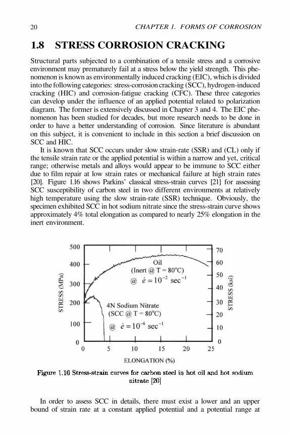
It is known that SCC occurs under slow strain-rate (SSR) and (CL) only ifthe tensile strain rate or the applied potential is within a narrow and yet, criticalrange; otherwise metals and alloys would appear to be immune to SCC eitherdue to film repair at low strain rates or mechanical failure at high strain rates[20]. Figure 1.16 shows Parkins’ classical stress-strain curves [21] for assessingSCC susceptibility of carbon steel in two different environments at relativelyhigh temperature using the slow strain-rate (SSR) technique. Obviously, thespecimen exhibited SCC in hot sodium nitrate since the stress-strain curve showsapproximately 4% total elongation as compared to nearly 25% elongation in theinert environment.
In order to assess SCC in details, there must exist a lower and an upperbound of strain rate at a constant applied potential and a potential range at
CHAPTER 1. FORMS OF CORROSION
1.8. STRESS CORROSION CRACKING 21
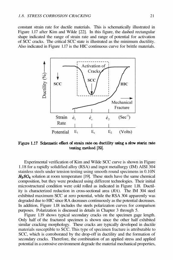
constant strain rate for ductile materials. This is schematically illustrated inFigure 1.17 after Kim and Wilde [22]. In this figure, the dashed rectangularshape indicated the range of strain rate and range of potential for activationof SCC cracks. The critical SCC state is illustrated as the minimum ductility.Also indicated in Figure 1.17 is the HIC continuous curve for brittle materials.
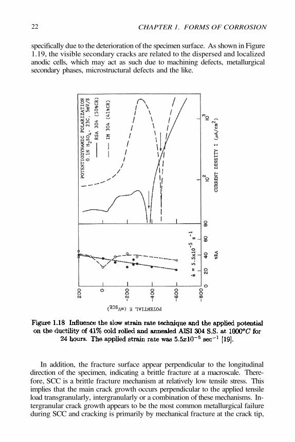
Experimental verification of Kim and Wilde SCC curve is shown in Figure1.18 for a rapidly solidified alloy (RSA) and ingot metallurgy (IM) AISI 304stainless steels under tension testing using smooth round specimens in 0.10N
solution at room temperature [19]. These steels have the same chemicalcomposition, but they were produced using different technologies. Their initialmicrostructural condition were cold rolled as indicated in Figure 1.18. Ductil-ity is characterized reduction in cross-sectional area (RA). The IM 304 steelexhibited maximum SCC at zero potential, while the RSA 304 apparently wasdegraded due to HIC since RA decreases continuously as the potential decreases.In addition, Figure 1.18 includes the steels polarization curves for comparisonpurposes. Polarization is discussed in details in Chapter 3 through 5.
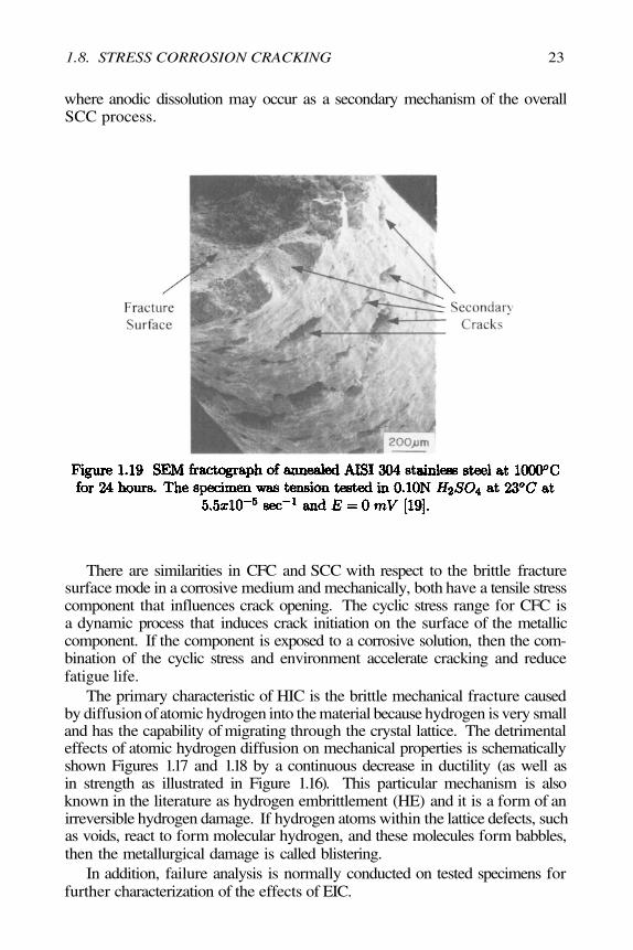
Figure 1.19 shows typical secondary cracks on the specimen gage length.Only half of the fractured specimen is shown since the other half exhibitedsimilar cracking morphology. These cracks are typically developed in ductilematerials susceptible to SCC. This type of specimen fracture is attributable toSCC, which is corroborated by the drop-off in ductility and the formation ofsecondary cracks. Therefore, the combination of an applied stress and appliedpotential in a corrosive environment degrade the material mechanical properties,
22
specifically due to the deterioration of the specimen surface. As shown in Figure1.19, the visible secondary cracks are related to the dispersed and localizedanodic cells, which may act as such due to machining defects, metallurgicalsecondary phases, microstructural defects and the like.
In addition, the fracture surface appear perpendicular to the longitudinaldirection of the specimen, indicating a brittle fracture at a macroscale. There-fore, SCC is a brittle fracture mechanism at relatively low tensile stress. Thisimplies that the main crack growth occurs perpendicular to the applied tensileload transgranularly, intergranularly or a combination of these mechanisms. In-tergranular crack growth appears to be the most common metallurgical failureduring SCC and cracking is primarily by mechanical fracture at the crack tip,
CHAPTER 1. FORMS OF CORROSION
1.8. STRESS CORROSION CRACKING 23
where anodic dissolution may occur as a secondary mechanism of the overallSCC process.
There are similarities in CFC and SCC with respect to the brittle fracturesurface mode in a corrosive medium and mechanically, both have a tensile stresscomponent that influences crack opening. The cyclic stress range for CFC isa dynamic process that induces crack initiation on the surface of the metalliccomponent. If the component is exposed to a corrosive solution, then the com-bination of the cyclic stress and environment accelerate cracking and reducefatigue life.
The primary characteristic of HIC is the brittle mechanical fracture causedby diffusion of atomic hydrogen into the material because hydrogen is very smalland has the capability of migrating through the crystal lattice. The detrimentaleffects of atomic hydrogen diffusion on mechanical properties is schematicallyshown Figures 1.17 and 1.18 by a continuous decrease in ductility (as well asin strength as illustrated in Figure 1.16). This particular mechanism is alsoknown in the literature as hydrogen embrittlement (HE) and it is a form of anirreversible hydrogen damage. If hydrogen atoms within the lattice defects, suchas voids, react to form molecular hydrogen, and these molecules form babbles,then the metallurgical damage is called blistering.
In addition, failure analysis is normally conducted on tested specimens forfurther characterization of the effects of EIC.
24
1.9 NONMETALLIC MATERIALS
CERAMICS. These are brittle and corrosion resistant compounds made outof metallic and nonmetallic elements. Some examples of ceramics are(alumina), SiC (silicon carbide), (magnesia), (magnetite), and
(zirconia). Other ceramics are made of basic ceramics and are known asbricks, clay, concrete, porcelain and the like. On the other hand, refractoriesare ceramics that withstand very high temperatures prior to melting, such as
(niobium carbide) @ 3615°C and @ 2852°C. In addition, ceramicsare immune to corrosion by almost all environments. Those which are notdissolve by chemical oxidation.
POLYMERS. These type of nonmetallic materials are very common in to-day’s society. A polymer is an organic compound, which means “poly ” manyand “meres ” parts and consists of repeated long-chain molecular structurebounded by covalent bonds [10-11]. Natural polymers are known as proteins,silks, deoxyribonucleic (DNA) among many others. On the other hand, syn-thetic polymers, such as nylon (polyamides), polyvinyl chloride (PVC), poly-acrylonitrite (PAN), polythylene, epoxy and many more are known as plastics,which are so important in nowadays society due to their vast and broad domes-tic and industrial applications. However, polymers are susceptible to degrada-tion in natural and synthetic environments, such as high temperatures (ther-mal degradation), moisture, radiation, ultraviolet light and mechanical agents.Degradation of polymers in natural environments is known as weathering due tothe effect of ultraviolet radiation from the sunlight, moisture, and temperature.Some oxidation agents of polymers can be found elsewhere [11]. In addition,degradation or damage of polymers can be classified as 1) oxidation damage ac-cording to the oxidation reaction due to high-energy ionizationradiation (radiolysis), such as electron beams, and and2) swelling caused by moisture and oxygen [11]. Furthermore, the polymer Rloses one electron leading to a degradation known a depolymerization.
WOODS. These are organic in nature and corrosion resistant in water anddiluted acids. Woods consist of cellulose fibers surrounded by lignin. The cel-lulose fibers are strong and yet, flexible, whereas the lignin is stiffer. Somewoods can dissolve in strong acids and diluted alkalies [5]. However, the woodtexture and properties play an important role in the material selection schemefor making violins, guitar, pianos, furniture, and houses.
CHAPTER 1. FORMS OF CORROSION
1.11 REFERENCES
[1] P. Morriset, Zinc el Alliages, “Zinc and Zinc Alloys,” in Corrosion: Metal-Environment Reactions, third edition, Edited by L.L. Shreir, R.A. Jarman, andG.T. Burstein, Butterworth-Heinemann, 20(1959)15.
[2] A.R.L. Chivers and F.C. Porter, “Zinc and Zinc Alloys” in Corro-sion: Metal/Environment Reactions, third edition, Edited by L.L. Shreir, R.A.Jarman, and G.T. Burstein, Butterworth-Heinemann, (1994) 4:172.
[3] C.H. Dale Nevison, “ Corrosion of Zinc” Corrosion, Vol. 13, Ninthedition, ASM international, (1987)756.
[4] J.C. Bailey, F.C. Porter,A.W. Pearson and R.A. Jarman, “Aluminumand Aluminum Alloys,” in Corrosion: Metal /Environment Reactions, thirdedition, Edited by L.L. Shreir,R.A. Jarman, and G.T. Burstein, Butterworth-Heinemann, (1994) 4.15.
[5] M.G. Fontana, “ Corrosion Engineering,” McGraw-Hill Book Company,(1986) 282,41.
[6] “Corrosion in Batteries and Fuel-cell Power Sources,” in Corrosion, Vol.13, Ninth edition, ASM International, (1987)1317.
[7] J.P. Gabano, “Lithium Battery Systems: An overview,” in LithiumBatteries, edited by J.P. Gabano, Academic Press, (1983)1-12.
1.10. SUMMARY 25
1.10 SUMMARY
The forms of corrosion encounter in diverse engineering structures have a com-mon oxidation mechanism represented by an anodic reaction, such as
eq. (1.1a). Thus, corrosion may be due to chemical or electro-chemical reactions. One common corrosion process is the formation of ferric hy-droxide, as indicated by the sequence of reactions given by eq. (1.7).Therefore, corrosion is classified as a localized or general oxidation process. Itmanifests its natural or forced behavior in various forms from atmospheric cor-rosion of steel structures to oral corrosion on dental alloys due to the effect ofsaliva and food.
In fact, the most common forms of corrosion are atmospheric and galvanic.Normally, a coating is applied on a structure to prevent or suppress oxidationsince it is a cost effective method. However, most coatings are synthetic poly-mers which oxidize in several environments leading to spalling-induced corrosionas shown in Figure 1.13. Ceramics, on the other hand, are made or formed bya combination of metallic and nonmetallic elements. Their unique characteris-tics for being corrosion and high temperature resistant materials do not excludethem from the corrosion schemes. Some strong acids are the cause of ceramicoxidation. The oxidation of polymers is represented by a molecular anodic re-action of the form This implies that the polymer R losesone electron leading to a degradation known as depolymerization. In addition,woods also degrade in strong acids and alkalies.

26
[8] S.L. Pohlman, “General Corrosion,” in Corrosion, Vol. 13, Ninth edi-tion, ASM International,(1987) 80
[9] S.C. Dexter, “Localized Corrosion,” in Corrosion, Vol. 13, ASM Inter-national, (1987)104.
[10] A. Kumar and R.K. Gupta, “Fundamentals of Polymers,” The McGraw-Hill Companies, Inc., New York, (1998).
[11] J.R. Fried, “Polymer Science and Technology,” Prentice Hall, Inc., NewJersey, (1995).
[12] C. Leygraf and T. Graedel, “Atmospheric Corrosion,” Wiley-InterscienceA John Wiley & Sons, Inc., Publication, New York, (2000)330-333.
[13] P. Arora and R.E. White, and M. Doyle, J. Electrochem. Soc., Vol.145, No. 10, (1998) 3647-3667.
[14] P. Arora, M. Doyle, and R.E. White, J. Electrochem. Soc., 146(10) (1999) 3543-3553.
[15] P. Arora, B.N. Popov, and R.E. White, J. Electrochem. Soc., Vol. 145,No. 3, (1998) 807-814.
[16] P. De Vidts, J. Delgado, B. Wu, D. See, K. Kosanovich, and R.E.White, J. Electrochem. Soc., Vol. 145, No. 11, (1998) 3874-3883.
[17] B. Wu and R.E. White, J. Electrochem. Soc., 148 (6) (2001) 3A5985-A609.
[18] W.G. Moffat, G.W. Pearsall and J. Wulff, “ The Structure and Proper-ties of Materials,” Vol. I, Structure, (1984) 51 as reported by W.D. Callister,“Materials Science and Engineering: An Introduction,” Six Edition, John Wiley& Sons, Inc., (2002) 33
[19] N. Perez, Ph.D. Dissertation, (1990)[20] R.N. Parkins, F. Mazza, J.J. Royuela and J.C. Scully, Br. Corrosion
Journal, 7 (1972) 154[21] R.N. Parkins, “Stress Corrosion Cracking - The Slow Strain Rate Tech-
nique,” ASTM STP 665, (1979) 5[22] C.D. Kim and B.E. Wilde, ASTM STP 665, (1979) 97
CHAPTER 1. FORMS OF CORROSION