Embed Size (px)
Citation preview

04/2010
USE AND MAINTENANCE MANUAL
MISTBLOWERS TURBOTEUTON
TOWED MISTBLOWERS
serie TURBOTEUTON - MAIA - TT:
T Polipo - T SuperSpalliera - RV-GDC - VLX - FXL
Read this manual carefully before use.
GB

2 unigreen
Summary
1 USING AND KEEPING THE USE AND MAINTENANCE MANUAL ................................. 4
1.1 COMPOSITION OF THE MANUAL ................................................................................................. 41.2 GUARANTEE .................................................................................................................................. 41.3 PRODUCT RESPONSIBILITY ........................................................................................................ 41.4 WARNING SIGNS IN THE MANUAL AND ON THE MACHINE....................................................... 42 SAFETY REGULATIONS AND RESIDUAL RISKS .......................................................... 5
2.1 INTENDED USE ............................................................................................................................. 62.2 PROHIBITED USE .......................................................................................................................... 62.3 USING CHEMICAL PRODUCTS .................................................................................................... 62.3.1 REGULATIONS FOR THE USE OF CHEMICAL PRODUCTS ........................................................ 6
2.4 RECOMMENDATIONS ................................................................................................................... 62.4.1 TAKING PRECAUTIONS AGAINST FIRE HAZARDS ..................................................................... 7
2.5 WEATHER CONDITIONS ............................................................................................................... 72.6 MACHINES DESIGNED TO BE USED ONLY WITH CLEAN WATER.............................................. 72.7 DRIVING ON THE ROAD................................................................................................................ 73 CHARACTERISTICS AND SPECIFICATIONS.................................................................. 7
3.1 TABLES OF FITTINGS ALLOWED ................................................................................................. 73.2 NOISE LEVEL OF THE MACHINE.................................................................................................. 83.3 STANDARDS OF REFERENCE: ..................................................................................................... 84 INSTRUCTIONS ................................................................................................................ 8
4.1 DESCRIPTION OF THE MACHINE ................................................................................................ 84.1.1 WORK STATIONS ........................................................................................................................... 84.1.2 HAND WASHING TANKS ................................................................................................................ 9
4.2 PRELIMINARY CHECKS ................................................................................................................ 94.3 TRANSPORTING AND MOVING THE MACHINE ........................................................................... 94.3.1 TOWED ATOMISERS ..................................................................................................................... 9
4.4 TRACTOR COUPLING ..................................................................................................................104.4.1 DRAWBAR WITH TOWING EYE OR FORK ..................................................................................104.4.2 STEERING DRAWBAR (COUPLED TO ELEVATOR) ....................................................................114.4.3 STEERING DRAWBAR (TOWING EYE) ........................................................................................114.4.4 ADJUSTABLE HUBS .....................................................................................................................114.4.5 HYDRAULIC CONNECTION TO THE DISTRIBUTORS .................................................................11
4.5 CARDAN SHAFT ...........................................................................................................................124.6 PUMP ............................................................................................................................................134.7 SUCTION FILTER ..........................................................................................................................134.8 PRESSURE REGULATOR .............................................................................................................144.8.1 COMPONENTS OF THE PRESSURE REGULATOR ....................................................................144.8.2 GENERAL INSTRUCTIONS ..........................................................................................................144.8.3 DELIVERY FILTERS (ONLY EQUIPPED MODELS) ......................................................................15
4.9 AUXILIARIES TAPS BLOCK ..........................................................................................................154.10 FILLING THE TANK........................................................................................................................164.11 TEST WITH CLEAN WATER ..........................................................................................................164.12 MIXING ..........................................................................................................................................174.12.1 MANUAL PREMIXING ...................................................................................................................174.12.2 PREMIXER ON COVER (OPTIONAL): ..........................................................................................174.12.2 PREMIXER ON COVER (OPTIONAL): ..........................................................................................174.12.3 PREMIXER ON HOPPER WITH TIN WASHER .............................................................................174.12.4 COVER WASHER FOR CHEMICAL CONTAINERS ......................................................................17
4.13 WASHING THE ATOMISER ...........................................................................................................184.13.1 CIRCUIT WASHER AND TANK WASHER......................................................................................185 BLOWER GROUP ........................................................................................................... 19
5.1 MULTIPLIER - FAN UNIT ...............................................................................................................195.5 CLUTCH ........................................................................................................................................195.3 DISTRIBUTOR ACCESSORIES ....................................................................................................205.3.1 POLIPO FOR ESPALIER ...............................................................................................................205.3.2 SUPER SPALLIERA FOR ESPALIER ............................................................................................205.3.3 RV BOOM FOR GDC .....................................................................................................................205.3.4 VLX BOOM FOR ESPALIER ..........................................................................................................215.3.5 FXL "UP AND OVER" BOOM FOR ESPALIER ..............................................................................21
5.4 HYDRAULICS ................................................................................................................................215.4.1 OIL FEED FROM TRACTOR .........................................................................................................225.4.2 CONTROLS FOR HYDRAULIC ACCESSORIES ...........................................................................22

unigreen 3
6 SPRAYING ....................................................................................................................... 23
6.1 DESCRIPTION OF THE DIFFUSERS...........................................................................................236.1 DESCRIPTION OF TYPE OF JETS ...............................................................................................236.2 DESCRIPTION OF TYPE OF NOZZLES .......................................................................................236.2.2 LOW VOLUME CONICAL NOZZLES (150-500L/HA) .....................................................................236.2.3 ANTI-DRIFT NOZZLES..................................................................................................................23
6.3 CALIBRATING TURBO TEUTON ...................................................................................................247 HAND LANCES ............................................................................................................... 24
8 MAINTENANCE ............................................................................................................... 25
8.1 PROGRAMMED MAINTENANCE ..................................................................................................258.2 ROUTINE MAINTENANCE ............................................................................................................258.2.1 CLEANING THE NOZZLES ...........................................................................................................258.2.2 LUBRICATION ...............................................................................................................................258.2.3 MULTIPLIER LUBRICATION ..........................................................................................................25
8.3 EXTRAORDINARY MAINTENANCE..............................................................................................268.4 REPAIRS ........................................................................................................................................268.5 STORAGE IN A WAREHOUSE AND TRANSPORTATION .............................................................268.6 PUTTING BACK INTO SERVICE AFTER WINTER LAYUP ...........................................................268.7 DEMOLITION AND DISPOSAL .....................................................................................................268.7.1 MATERIALS FOR DEMOLITION ...................................................................................................268.7.2 INDICATIONS FOR A SUITABLE TREATMENT OF WASTE .........................................................268.7.3 ELECTRICAL AND ELECTRONIC APPARATUS WASTE (EEAW) ................................................27
TABLES FOR CALIBRATING POLIPO 4+4 (8 NOZZLES) NARROW ROWS ............... 28
TABLES FOR CALIBRATING POLIPO 4+4 (16 NOZZLES) NARROW ROWS ............. 28
TABLES FOR CALIBRATING POLIPO 4+4 (8 NOZZLES) WIDE ROWS OPTIONAL .. 29
TABLES FOR CALIBRATING POLIPO 4+4 (16 NOZZLES) WIDE ROWS OPTIONAL 29
TABLES FOR CALIBRATING POLIPO 5+5 (20 NOZZLES) NARROW ROWS ............. 30
TABLES FOR CALIBRATING POLIPO 5+5 (10 NOZZLES) NARROW ROWS ............. 30
TABLES FOR CALIBRATING POLIPO 5+5 (20 NOZZLES) WIDE ROWS OPTIONAL 31
TABLES FOR CALIBRATING POLIPO 5+5 (10 NOZZLES) WIDE ROWS OPTIONAL 31
TABLES FOR CALIBRATING SUPER SPALLIERA 4+4 (16 NOZZLES) ...................... 32
TABLES FOR CALIBRATING SUPER SPALLIERA 4+4 (8 NOZZLES) ........................ 32
TABLES FOR CALIBRATING RV-GDC 5+5 (10 NOZZLES) .......................................... 33
TABLES FOR CALIBRATING RV-GDC 5+5 (20 NOZZLES) .......................................... 33
TABLES FOR CALIBRATING VLX 6+6 (24 NOZZLES) ................................................ 34
TABLES FOR CALIBRATING VLX 6+6 (12 NOZZLES) ................................................. 34
TABLES FOR CALIBRATING FXL2 ROWS 12 DIFFUSERS (12 NOZZLES) ................ 35
TABLES FOR CALIBRATING FXL2 ROWS 12 DIFFUSERS (24 NOZZLES) ................ 35
TABLES FOR CALIBRATING FXL3 ROWS 18 DIFFUSERS (36 NOZZLES) ................ 36
TABLES FOR CALIBRATING FXL3 ROWS 18 DIFFUSERS (18 NOZZLES) ................ 36
TAB. 3 TABLE OF DELIVERY OF NOZZLES FOR ATOMISERS .............................................. 37
TABLE 4-5 TABLES OF DELIVERY OF NOZZLES FOR HAND LANCES ................................... 37
TABLE 7 TABLE OF PROGRAMMED MAINTENANCE ................................................................ 38
TAB.17B ALLOWED FITTINGS ...................................................................................................... 39

4 unigreen
Thank you for having chosen UNIGREEN.The product you purchased has been designed and built with the greatestattention to the safety of the operator and the environment, nevertheless thereare still some residual risks due to the nature of the product used.For this reason we recommend reading all of this manual to avoid makingmistakes in the first period of use and to get the most out of the working life ofthe sprayer in time, doing the programmed maintenance at regular intervals.
1 USING AND KEEPING THE USE AND MAINTENANCE MANUAL
The manual is an integral part of the machine and should be kept in a safeplace where it can be reached easily for consultation.
1.1 COMPOSITION OF THE MANUAL
This manual consists of various parts to make it easier to consult by subjectand to avoid repetitions; the following are part of the manual:a) pump handbookb) pressure regulator handbook (manual or electric)c) spraying computer handbook (if fitted)d) optional accessories handbooks (marker, premix, cardan shaft, etc.)UNIGREEN reserves the right to make changes to the manual without priorwarning and the normal printing cycles may vary slightly.
1.2 GUARANTEE
The enclosed card indicates the conditions of the UNIGREEN guarantee. TheUNIGREEN guarantee covers the repair or replacement of parts consideredmanufacturing flaws, according to the unquestionable judgement of UNIGREEN,only after the authorised agent for that zone has verified the fault.Ambit of the guaranteeThe guarantee doesn’t cover cases of normal wear, negligent use, poormaintenance and/or improper use.The following materials subject to normal wear are not covered by the
guarantee: gaskets and seals, diaphragms, seal rings, tubes and pipes,nozzles, pressure gauges, oil, tyres, friction material of the clutches.Evident cases of negligence include: work speed over that indicated in thespraying tables in the handbook (or too high for the conditions of the terrain),use of herbicide booms without an auto-levelling system or with the auto-levelling system blocked, power-takeoff speed over 540 rpm.Mounted mistblowers: activation of the three-point elevator with cardan shaftengaged and power-takeoff operational.And anything else indicated in the present Use and Maintenance Manual.Maintenance:The guarantee is void if the maintenance indicated in the tables in this manualisn’t respected, regarding the period and deadline of the interventions, washingthe machine and the circuit at the end of the treatment.Improper use:The use the UNIGREEN machines are designed for is indicated in this manual,any other use is forbidden and makes the guarantee void.
1.3 PRODUCT RESPONSIBILITY
UNIGREEN spa is not responsible if:a) During the working life of the machine the normal maintenance operationsaren’t performed and documented as indicated in this handbook, in theenclosed handbooks of the pumps-motors-regulators-etc. and in any case asis customary for the normal maintenance of mechanical machinery.b) The machine is equipped with non original accessories or components orparts that aren’t acknowledged by UNIGREEN as their own.c) The machine is equipped with original accessories or components thatare unsuitable in the measurements, weight or version for the same.Please consult the page of available and recommended fittings.d) Not following the instructions in the manual whether totally or partially.e) Modifications made to the machine that haven’t been authorised byUNIGREEN.
1.4 WARNING SIGNS IN THE MANUAL AND ON THE MACHINE
Below you will find all of the pictograms on the machine (see FIG.1 for theirposition), in order to illustrate the warnings, the prohibitions and the correctmethod of use.The operations that require particular attention are shown in the images besidethe text.
Libretto composito, consultare ifascicoli specifici dei vari componenti

unigreen 5
2 SAFETY REGULATIONS AND RESIDUAL RISKS
In relation to safety, the following terms will be used:Dangerous zones: any zone inside and/or near the machine where thepresence of a person exposed constitutes a risk for the safety and health ofthe same person.Person exposed: any person who has their body or any part of their body in adangerous zone.
Before starting the machine, the operator must check for any visible faults inthe safety devices and the machine itself.Never start the machine until you have told anyone in the range of action ofthe machine to move away and they have done so.The protective devices must not be removed or disabled when the machine isrunning.It is obligatory to keep all the plates with danger and safety signs in perfectconditions. If they get damaged or deteriorate, replace them in good time.Replace parts believed to be faulty with others indicated by UNIGREEN.NEVER try makeshift or hazardous solutions.Don’t wear clothes, jewellery, accessories, or anything else that can getcaught in the moving machine members.Pay the greatest attention to all the warning and danger signs on the machine.Don’t use the machine for any other purpose other than that indicated in themanual.The machine has been designed and built with the appropriate devices toguarantee the safety of the user.In any case there are some residual risks associated with the improper use ofthe machine by the operator; for this purpose danger signs and symbols andprohibitions are applied near some parts of the machine (see previouspictograms).
Key to the symbols
1- Read the Use and Maintenance manual2- Stop the machine and read the manual beforeevery intervention3- Don’t lubricate while running4- Don’t drink5- Don’t dispose of residue liquids in theenvironment6- No smoking7- Danger, risk or injury, don’t get near themachine until the moving machine members havestopped8- Danger of crushing, don’t get your hands nearthe moving mechanical machine members9- Danger, risk or injury caused by fluids underpressure10- Don’t climb on the machine during work ortransfers11- Don’t climb on the tank12- Don’t enter in the tank13- Wearing earmuffs is obligatory14- Wearing a face mask is obligatory15- Wearing safety footwear is obligatory16- Wearing protective gloves is obligatory17- Wearing protective overalls is obligatory18- Use a working pressure under that indicated inred on the manometer.19- Don’t get your hands near the moving cardanshaft20- Make sure power-takeoff of the tractor turns inthe right direction and runs at the right speed.21- Don’t remove the protecting device with fanmoving.22- Material shooting off the machine, stand at asafe distance.23- Don’t stand between the machine and thetractor.
2019 2221
21 63 4 5
87 129 10 11
1413 1815 16 17
23
INDICATIVE POSITION OF THE WARNING SIGNSON THE MISTBLOWERSNB: the position may vary on the basis of thecharacteristics of the model.
da 1 a 1819+20
23FIG.1
21+22
11+12

6 unigreen
2.1 INTENDED USE
The sprayer in this series is built for agricultural use. The materials used areresistant to normal chemical products used in agricultural spraying (orherbicides) at the time of construction.Any other use is not allowed and the manufacturer is not responsible for anydamage caused by aggressive, dense or sticky chemicals.THE USE OF THE MACHINE BY PERSONS UNDER 18 YEARS OF AGE ISSTRICTLY FORBIDDENThe use of liquid fertilizers in suspension is not allowed, while the use of thesame in a solution is possible if requested when the machine is ordered fromUnigreen and in any case changing some of the parts described in thehandbooks of the regulator, such as the manometer (stainless steel), thenozzles (large diameter ceramic) and eliminating the fine mesh filters toprevent blockages.
2.2 PROHIBITED USE
Using the machine with the following products is strictly forbidden:= Paints of any kind and type= Solvents or thinners for paints of any kind and type= Combustibles or lubricants of any kind and type= LPG or gas of any kind and type= Flammable liquids of any kind and type= Liquid foodstuffs, whether for animals or humans= Liquids containing granules or consistent solids= Mixtures of various incompatible chemical products= Liquid fertilizer or manure in suspension with lumps and/or that is
particularly dense= Liquids with a temperature of over 40°C= Any products that aren’t suitable for the specific use of the machine.
2.3 USING CHEMICAL PRODUCTS
All pesticides or herbicides can be dangerous to humans and the environmentif used erroneously or inadvertently.Therefore we recommend that only suitably trained persons should use theseproducts (license) and in any case only after having carefully read theinstructions on the container.
2.3.1 REGULATIONS FOR THE USE OF CHEMICAL PRODUCTS
Some recommendations for avoiding damage and accidents:= Keep the machine in a suitable, protected place with no access forchildren or strangers= Handle the products with care, wearing rubber acid-proof gloves, goggles-face masks or filtering helmets, overalls made of water-repellent fabrics orTIVEK and boots made of rubber or similar materials.= If chemical products or mixtures of product come into contact with theeyes or are swallowed consult a doctor immediately, taking the label of theproduct with you.= Wash all clothes that come into contact with the chemical, whether dilutedor undiluted, thoroughly before using them again.= Don’t smoke, drink or eat when preparing or spraying the mix or near or inthe fields treated.= DON’T ENTER THE TANK: the residues of a chemical product can causepoisoning and suffocation.= When spraying, respect safe distances from residential areas, watercourses, roads, sports centres and public parks or paths.= Thoroughly wash the containers of plant protection products using therelevant accessories, rinsing several times with clean water. The liquids usedfor washing can be used for treatment.= Collect the washed containers and send them to the relevant collectioncentres. Never dispose of them in the environment and don’t use them againfor any other purpose. It is good practice to knock a hole in the bottom of thetins so they can’t be used again.= When you have finished spraying, wash the sprayer thoroughly, dilutingthe residues with a quantity of water at least 10 times that of the residues,spraying the resulting mix over the treated field.
2.4 RECOMMENDATIONS
a) Refer to the present handbook for the use and maintenance of the frame,tank, auto-levelling systems, elevators, mechanical and hydraulic herbicidebooms, spray booms and hose reels.

unigreen 7
Refer to the enclosed handbooks for the use and maintenance of the pump andpressure regulator and any accessories or motors.b) Please contact the agent in your zone, the nearest authorised workshop orUNIGREEN S.p.A. directly for any repairs the user feels they aren’t capable ofperforming alone. (see point 8.4)c) Due to the complexity of the equipment and the variety of technologies used(mechanical, hydraulic, oil-pressure and electrotechnical) operators must notdismantle or modify the equipment. All of the relevant operations must beperformed by specialised personnel, authorised by UNIGREEN S.p.A.
2.4.1 TAKING PRECAUTIONS AGAINST FIRE HAZARDS
Don’t use naked flames or heat sources near the machines.The mistblowers are made with many materials that derive from petroleum: tanks,tubes, pipes and hoses, wheels and plastic parts; furthermore the presence of oilsof various nature and residues of chemical products make them potentiallyflammable.
2.5 WEATHER CONDITIONS
We recommend spraying in the early hours of the morning or late in the afternoon,avoiding the hottest time of day.Never do any spraying if it’s raining or rain is forecast.Don’t spray in strong wind or in any case, in winds above 3/5 m/second.If you have to spray in windy conditions, use relatively low pressures to obtainquite large drops that are less sensitive to drifting (being heavier the wind has lesseffect). There are also special anti-drift nozzles available from UNIGREEN S.p.A.;for information, please contact our offices.
2.6 MACHINES DESIGNED TO BE USED ONLY WITH CLEAN WATER
There are versions of the machines designed only to be used with a hose reel forwashing with cold clean water.These machines cannot be used with chemical products as they don’t have some ofthe devices or accessories that are needed to use these products safely.These machines are identified by the word “washing” on the CE plate.
2.7 DRIVING ON THE ROAD
The towed mistblowers are not specifically designed for road use. Nevertheless,many models are also available in the version homologated for road traffic with thetank empty.You should check with your local reseller on the correct couplings to use and usetractors that meet the regulations in force.
3 CHARACTERISTICS AND SPECIFICATIONS
This handbook is valid for mounted and towed mistblowers with axial fans forphytosanitary treatment in orchards and vineyards, in any case for arborealcultivation in rows of varying nature and type.It is also valid for cannon mistblowers for the phytosanitary treatment of tall plantsand forest trees such as poplars or similar.The axial mistblowers produce a mixed spray, breaking the drops with thepressure and the speed of the air produced by the fan.These mistblowers produced by UNIGREEN SPA are identified by the CE plate(FIG. 2) bearing one of the marks indicated in the tables of the allowed fittings(see the following paragraph).
3.1 TABLES OF FITTINGS ALLOWED
Table N° 18b let you identify the version of your machine indicating the basicequipment and all the possible fittings available (optional).You can also find the other fittings allowed or other versions to meet yourrequirements in the future.
THE EQUIPMENT DEFINED IN THE TABLES OF THIS HANDBOOK (TAB: 18b,page 42) SHOULD BE CONSIDERED BINDING FOR THE VALIDITY OF THEDECLARATION OF CONFORMITY.Other fittings or setups of basic components and/or optionals should beconsidered unsafe and therefore are not covered by the guarantee and aren’tUNIGREEN’s responsibility.The same goes for fittings realised with components or accessories that aren’toriginal UNIGREEN parts.UNIGREEN accessories can easily be identified by the label with the yellowbackground “ORIGINAL UNIGREEN ACCESSORY”
TYPE : .......................................................................
code: ........................................ N˚ ...........................
massa a vuoto: ..........................Kg. max press. : ........... bar net mass
massa totale ammessa: .............................. Kg. total mass
via Rinaldi, 105 - Reggio Emilia ITALIA
ANNOYEAR
20 .......
made inItaly
FIG.2

8 unigreen
3.2 NOISE LEVEL OF THE MACHINE
Use earmuffs to protect your ears when using the machine, below you will find thedata on the maximum noise levels during work.
Atomisers with centrifugal fan rotor (Turboteuton)ACOUSTIC POWER LEVEL emitted by the machine: 123,8 dBA in 2nd gearACOUSTIC POWER LEVEL AT THE OPERATOR’S POSITION emitted by themachine: 103,2 dBA in 2nd gear
Readings taken in accordance with the following standards:Machines Directive 2006/42/CELegislative Decree D.Lgs. n°292 of the 4th of September 2002 concerning theenvironmental acoustic emission of machines and equipment for use outdoors.UNI EN ISO 4254-1:2006.
3.3 STANDARDS OF REFERENCE:
- MACHINES DIRECTIVE 2006/42/CE.- D.Lgs. 81/08 Unique text for safety and hygiene in working places.-UNI EN ISO 12100-1/Apr.2005 : Machinery safety - Fundamental concepts, generaldesign principles - Part 1: basic terminology, methodology-UNI EN ISO 12100-2/Apr.2005 : Machinery safety - Fundamental concepts, generaldesign principles - Part 2: Technical principles-UNI EN ISO 13857: May 2008 Machinery safety, safe distances to avoid reachinghazardous areas with upper limbs.-UNI EN 349/November 2008: Machinery safety, minimum spaces to prevent crushingof body parts-UNI EN 907/Nov.1998: Agricultural and forestry machinery - Sprayers and spreadersof liquid fertilizers - Safety.-UNI EN ISO 13849-1: February 2007: Machinery safety - Fundamental concepts,general design principles-UNI EN 982/January 2009: Machinery safety. Safety requisites relevant to systemsand their components for hydraulic and pneumatic transmissions. Hydraulics.-UNI EN ISO 4254-1/June 2006: Agricultural machines - Safety - Part 1: Generalrequisites-ISO 11684/1995: Pictograms - general principles.
4 INSTRUCTIONS
To use the machine the personnel must be suitably trained on the basis of theregulations in force on safety and hygiene at work.THE USE OF THE MACHINE FOR PERSONS UNDER 18 YEARS OF AGE ISSTRICTLY FORBIDDEN
4.1 DESCRIPTION OF THE MACHINE
The mistblowers consist of a structural steel frame and a polyester tank reinforcedwith fibreglass or high-density polyethylene. The frame is hot-galvanised. The tank iseasy to empty and this makes it possible to use the machine even on hillsides.The pumps are generally diaphragm pumps but in some cases they are fitted withpistons.The accessories for completing the fitting, non-drip jets and ceramic nozzles makethe UNIGREEN mistblower a highly qualified and efficient piece of equipment.
4.1.1 WORK STATIONS
The use of this machine does not envisage an operator standing constantly near thesame, the operator normally sits in the cab of the tractor.During calibration and maintenance operations the operator will be working near themachine at ground level (for all the calibration and maintenance operations refer tothe relevant chapters).In case of operations that request the entry to parts of the machines located at 1,5mt. height ,it is advised to use a ladder at rule; the ladder shall be positioned steadyon a flat ground not yielding and with the machine at a standstill and braked.In some special models with controls above 1.5 metres there is a platform to makethese operations easier.This platform must only be used with the machine stopped.

unigreen 9
4.1.2 HAND WASHING TANKS
The mistblowers are supplied with an auxiliary hand-washing tank with cleanwater and a hand tap.This tank must always be supplied with water and the inside must be cleanso you can wash any parts of the body that come into contact with thechemical product used.Never drink the liquid inside.
4.2 PRELIMINARY CHECKS
When you receive the machine, check that it is complete and no parts aremissing.If there are any damaged parts, inform your local reseller or UNIGREENdirectly in good time.When the machine is delivered, make sure you ask:
a) that the machine is delivered with all of its parts fitted and that the fittingmeets the requisites in table N° 17b (page 39).This procedure is necessary because for reasons of space duringtransportation the machine is often delivered partially dismantled.
b) that it is tested in your presence in particular checking:= that the suction filter and the inside of the tank are clean and free ofwork residues.= that the connections are made correctly following the basic layout (FIG.N° 16, page 17).= that the hose clips and all the unions and connections are tightenedproperly.= that all of the protective covers are fitted solidly to the machine, inparticular the protective cover of the power-takeoff of the pump.= that the multiplier is sufficiently supplied with lubricant oil.= that the zone where the fan turns hasn’t been bent by knocks duringtransportation.
4.3 TRANSPORTING AND MOVING THE MACHINE
Every time you have to lift the machine, before starting the operation, alwaysmake sure the lifting gear and the relevant tools and equipment (cables,hooks, etc..) are suitable for lifting the load and check the stability of thesame.It is forbidden to unhook and move the machine with the tank full.
The dry weight of the machine at the maximum level of fitting and with all theaccessories allowed is stamped on the nameplate (FIG.2); use slings andlifting gear with a adequate load-bearing capacity (FIG.3).Never lift or move the mistblowers by hand if there is liquid in the tank. Themachine will weigh more and the movement of the liquid can change thecentre of gravity causing uncontrolled movements.We recommend using slings as shown in the figure, the lifting points to useon the machine are indicated with the relevant symbol.Don’t lift the machine with the forks of a forklift truck because the machinecan tip over due to the overhanging weight of the blower group.Don’t pass or stand under the machine when it is being lifted.
4.3.1 TOWED ATOMISERS
PARKINGDon’t stand the mistblower on unstable ground or steep slopes, the machineis designed to be parked safely on compact ground with a slope of up to 8.5°using the relevant chocks (FIG. 4) in the following way:- Machine parked with drawbar uphill (max 8.5°), place the chocks behindthe wheels.- Machine parked with drawbar downhill (max 8.5°), place the chocks in frontof the wheels.- Machine parked across the slope (max 8.5°), place one chock in front ofthe drawbar wheel (in the direction of the slope) and the other in front of thewheel uphill.
FIG.3
FIG.4
This symbol identifies the cleanwater tank on the machine usedto wash your hands
This symbolidentifies thecoupling pointsof the machine
Only move and lift the machinewith the tank empty

10 unigreen
MOVINGTo lift the machine, follow the instructions above.The towed mistblowers have an extendable drawbar parking wheel so themachine can be moved around by hand on flat, compact ground, with thetank empty.To make moving the mistblower around easier when it is disconnected from thetractor, on the machine and on the drawbar there are supports for positioning the:- cardan shaft: hinged rest on the drawbar parking wheel.- manual pressure regulator: bayonet housing on the drawbar.- electric pressure regulator: pushbutton panel support (the cable must becoiled around the same to stop it getting in the way).- Brake levers if fitted: bayonet housing on the drawbar.
4.4 TRACTOR COUPLING
= The tractor must be equipped with a 1”3/8 ASAE DIN 9611/A at 550 rpmpower-takeoff capable of supplying the power necessary for operating themachine.= It must have a towing hitch (towed mistblowers with a towing eye or forkdrawbar) and a three-point elevator (for mounted machines and a steeringdrawbar for towed machines) suitable for safely bearing the weight of themistblower.= It must be able to tow the maximum overall mass of the machine.All of the characteristics required are indicated in the fittings tables 18b onpage 42 (the total mass is also indicated on the CE plate on the machine).WARNING: make sure there are no persons or things near the
mistblower before starting the machine and while you are using it.
4.4.1 DRAWBAR WITH TOWING EYE OR FORK
= Check that the weight on the hook can be supported by the tractor (themaximum weights on the drawbar are indicated in the fittings tables 18b onpage 42)= Hook the drawbar to the towing hitch adjusting the height of the samehook so the tank of the sprayer is horizontal. You can also rotate the drawbaras shown (FIG. 5).= Retract the parking drawbar wheel (or foot) so it doesn’t get damagedduring work (FIG. 5b).NB: to perform these operations, check the stability of the machine andobserve all the indications relevant to safety in the paragraphs 4.3TRANSPORTATION AND MAINTENANCE, 8 MAINTENANCE, and 8.4REPAIRS.= Position the pressure regulator in a place where it is easy to reach fromthe driver’s seat. Don’t carry liquids under pressure inside the cabin; use therelevant electrical or cable controls for these tractors.= Check that the pipes of the pressure regulator (or the electrical cables ona pushbutton control panel) don’t get in the way and are positioned at a safedistance from the cardan shaft and the wheels of the tractor.= You must purchase the brake kit if the towed mistblower will be used onhillsides.
FIG. 5
FIG. 5b
The foot wheel in the mistblower’s workposition.

unigreen 11
4.4.2 STEERING DRAWBAR (COUPLED TO ELEVATOR)
= Check that the diameter of the elevator coupling pins coincide with thetractor (adapter bushes are available on request).= Check that the weight on the elevator can be supported by the tractor (themaximum weights on the drawbar are indicated in the fittings tables 18b onpage 40)= Check that the steering joint is lubricated with grease.= Connect the drawbar to the elevator using the elevator control to keep thetank of the sprayer horizontal.= When you have connected the drawbar proceed as for the towing eyedrawbar.
4.4.3 STEERING DRAWBAR (TOWING EYE)
Special steering drawbars with a towing eye, homologated for road traffic, areavailable on request and another manual is supplied with the instructions onusing this.
4.4.4 ADJUSTABLE HUBS
If the mistblower has adjustable hubs you can adjust the height of the machine;to do this, lift the machine as explained in point 4.3, loosen the 8 axel fixingscrews, pull off the hub and position it in the desired position.
WARNING: the wheelbase should only be adjusted by qualified personnel.The length L of the part of the axle inserted in the frame must never be lessthan 250 mm, the wrong positioning of the hubs can weaken the axle and causedamage.
4.4.5 HYDRAULIC CONNECTION TO THE DISTRIBUTORS
Machines that need a hydraulic connection to drive the movements of thecannon are equipped with 1/2", “Push-Pull”, quick-fit male couplings. You canconnect the pipes by simply pushing them in, making sure you:- do so only with the engine turned off;- lower any tools connected to the elevator of the tractor;- carefully clean the two parts that will be coupled
Warning: the hydraulic cylinders used are the “Double Effect” type.Consult the use and maintenance manual of the tractor.

12 unigreen
4.5 CARDAN SHAFT
In some models this is supplied on request.The cardan shaft must bear the CE mark.It must always have its own instructions that must be followed scrupulouslyand it should come with a cover bearing the mark, integrated in every part.You should have previously checked the length to avoid:= if it is too long, DANGEROUS THRUST ON THE PUMP SHAFT= if too short, the POSSIBILITY OF DANGEROUS BREAKAGES
THE MINIMUM OVERLAP OF THE TWO TELESCOPIC TUBES MUSTNEVER BE LESS THAN 1/3 OF THE LENGTH OF THE TUBES.
The power that can be transmitted by the cardan shaft must be at leastequal to that required to run the mistblower.These power ratings are indicated in tables N° 18b (page 40).
a) Hook any safety chains to solid anchor pointsb) Check that the button or ringnut “E” (FIG. 6) is correctly engaged andblocked both on the pump side and on the tractor side.c) Don’t exceed an inclination of 30° in any direction for any reasond) With the machine stopped, periodically grease the spiders and thepipes, keeping the connecting zone particularly clean.e) Avoid letting the end of the cardan shaft come into contact with theground with the machine stopped; use the relevant support on someversions for this, if your machine has no support, hook the external safetychain to a part of the frame of the machine (ex. control unit support).f) For towed mistblowers with a steering drawbar, be very careful not to liftthe arms of the elevator too high to prevent the cardan shaft touching partsof the drawbar.l) For towed mistblowers, avoid very tight steering circles with the cardanshaft turning (max 30°) as this could damage both the cardan shaft and thefeet of the pump (FIG. 7).
NEVER USE THE CARDAN TRANSMISSION IF THE FOLLOWINGPROTECTIVE COVERS ARE MISSING:- TRACTOR POWER-TAKEOFF PROTECTIVE COVER- CARDAN SHAFT PROTECTIVE COVER- FIXED PROTECTIVE COVER ON THE PUMP SHAFT
FIG. 7
FIG. 6

unigreen 13
4.6 PUMP
When using the pump scrupulously observe the instructions in the enclosedhandbook supplied by the manufacturer.The pump can be identified by the ratings plate on the same; the main dataon the pressure and delivery are easy to find on this plate.Normally the pumps mustn’t exceed 550 RPM; a higher speed won’t improveperformance but there is a risk of compromising the life and safety of thepump.There is a safety valve on the pump, calibrated to prevent overpressure.Don’t tamper with this valve for any reason and don’t block or obstruct thepipes connected to it in any way.
4.7 SUCTION FILTER
The sprayer is fitted with a suction filter with filter cartridges that haveroughly a 50-gauge mesh, which is equivalent to a hole of 0.4 at 0.35 mm.An efficient filter lets the sprayer work properly.You should periodically check that the filter cartridge is clean, this checkshould be done more often if there are impurities in the liquid.To inspect the filter cartridge wear rubber acid-proof gloves as the liquid inthe filter can come into contact with your hands when you open the filter.Don’t perform this operation with the pump running as the depressionproduced blocks the cover preventing the removal.
Before removing the cover of the filter, make sure that the same is isolatedfrom the tubing by unscrewing the relevant rear valve (FIG. N°8) or on the 3-way deviator (FIG. N° 10, page 14).After washing the cartridge, reassemble the cover making sure you connectthe same to the circuit again, using the valves described above in theopposite order.WARNING!: Don’t disperse the washing residues in the environment!!
FIG. 8
Valve

14 unigreen
4.8 PRESSURE REGULATOR
To use the pressure regulator, follow the instructions in the enclosed hand-book scrupulously. The pressure regulator controls all of the most importantspraying functions, the thorough knowledge of its functions makes work easierand more precise.The working pressure and the maximum pressure of the sprayer are deter-mined by the pressure regulator which also protects the circuit fromoverpressure in any work conditions. (In serious but very rare cases, if theconnecting pipes get blocked the pressure relief valve lets the pressure off)In some setups there may be a pump that can reach a pressure of 50 barcontrolled by a regulator designed for 20 bar. In this case the maximumpressure that can be reached is 20 bar.The regulators can be manual, mounted on the sprayer or at a distance tomake the controls easier to use; or electrical with a control panel in the cabin.There are also regulator versions with mechanical remote controls with acable. If the tractor has a waterproof cabin the use of electrical controls isobligatory.
4.8.1 COMPONENTS OF THE PRESSURE REGULATOR
Below you will find the indications for the main models fitted on Unigreenproducts.
A main ON-OFF command: “open” lets the fluid flow into the circuit in use;“closed” empties the tank.B maximum pressure valve: adjusted by hand with the relevant knob (drainsthe excess liquid when the set pressure is reached).C jets section tap: opens the corresponding jet boom or drains to thecompensation regulator (G).D auxiliary tap: can be used for various accessories (it is always manual).E volumetric pressure valve (proportional):(when present) it regulates the spraying pressure. The valve automaticallycompensates variations in speed (within the scope of the same gear ratio),keeping the quantity of liquid supplied per surface unit (litres/hectare)unchanged.F self-cleaning filter: filters the delivery liquid.G compensation regulators: suitably regulated, these make it possible tokeep the pressure constant when one or more sections of jets is closed, theydon’t influence treatments with the boom fully open.H manometer: indicates the working pressure.
Connections:R1 supply unionR2 drain unionR3 volumetric drain unionR4 jets section delivery unionR5 auxiliary delivery union
Control box for GCP ELETTRICO electrical regulators
I1 main control valve switchI2 volumetric pressure valve switch (proportional)I3 jets section valves switches
4.8.2 GENERAL INSTRUCTIONS
When using the pressure regulator, scrupulously observe the instructions inthe enclosed handbook, below you will find generic indications for the majormodels fitted by Unigreen.All the regulation and adjustment tests must be carried out with clean
water.
Pressure regulators without a volumetric valve (GCP3-way - GRH-RVA)Adjusting the maximum pressure valve= put main control A in the drain position (“OFF”).= loosen the hand wheel of maximum pressure valve B completely(anticlockwise).= start the pump by activating the power-takeoff of the tractor at 540rpm= open main control A (position “ON”), the manometer will be activated= open all of the section valves C (position “ON”)
Don’t use the sprayerwithout having consultedthe enclosed handbook.

unigreen 15
= adjust maximum pressure valve B to the working value (in any case lessthan the safe maximum pressure the system can reach).Pressure regulators with a volumetric valve (GCP ELETTRICO)
Adjusting the maximum pressure valve= put main control A in the drain position (“OFF”).= loosen the hand wheel of maximum pressure valve B completely(anticlockwise).= open volumetric valve E completely.= start the pump by activating the power-takeoff of the tractor at 540rpm= open main control A (position “ON”), the manometer will be activated= open the drain tap on filter F slightly (only GCP ELETTRICO).= close volumetric valve E completely. If the pressure rises over the maximumlimit of the system, make sure maximum pressure valve B is open (see previousindications)= open all of the section valves C (position “ON”)= adjust maximum pressure valve B to a value over that of the workingpressure (generally 10-14 bar) and in any case lower than the safe maximumpressure that the system can reach.
Adjusting the volumetric pressure.= with the volumetric pressure valve E adjust the pressure to the value thetreatment will be done at (the pressure is indicated on the nozzles tables on thebasis of the tractor speed and litres/hectare to spray)Warning! The working pressure must be adjusted with the volumetric valve
and not with the maximum pressure valve. In the case the working
pressure is too near to the calibrated pressure of the maximum pressure
valve, the proportional valve may not be able to compensate the speed
variations correctly.
Adjusting the compensated returns= close only one tap of section C (position “OFF”).= adjust the corresponding compensator G until you return to the pressure setpreviously (displayed on the manometer).= open and close the tap of section C and check that the pressure remainsconstant.= repeat the above operations for all the section taps.If the types of nozzles aren’t changed the regulations carried out will guarantee aconstant spraying of the liquid also per treatments that are done at differentworking pressures.NB: if the type of nozzle is changed then the calibrating will have to be doneagain.
4.8.3 DELIVERY FILTERS (ONLY EQUIPPED MODELS)
This is particularly useful when using small nozzles (low volume), they arenormally mounted on the jet booms and have a filter cartridge with a 40-gaugemesh (the equivalent of a 0.4 mm hole).At the end of each treatment cycle you should clean the cartridge: turn the jets tothe closed position, put the command under pressure and open the tap underthe filter to drain the tank for a few minutes.You should clean the cartridge by hand periodically, on the basis of the productused. Stop the pump to clean. Wear rubber gloves and the other personalprotective equipment when cleaning.
4.9 AUXILIARIES TAPS BLOCK
A collector is installed (FIG. 9) in the machines with taps for the utilities andaccessories, which require a working pressure that is independent from thespraying pressure:- Tank washing jet: see paragraph 4.13.1 - Ejector: see paragraph 4.10- Agitators (2 independent taps): see paragraph 4.12The taps are identified by the relevant sticker and the methods of use aredescribed in the paragraphs indicated.The pressure is normally regulated to 30-35 bar with the relevant valve (using ayellow knob) and displayed on the manometer installed; opening the utilitiesmakes the pressure drop.
FIG. 9
Tank
rinsing
Ejector
Agitator 1

16 unigreen
4.10 FILLING THE TANK
The machines for defensive crop treatments, in consideration of the safety ofpersons, animals and the protection of the environment, must only be filledindirectly from open water courses and only by free-falling water from thewaterworks.The pipe used for filling must never come into contact with the liquid inside thetank and therefore the water must always fall over the upper edge of the fillinginlet and through the filter installed on it.The tank is fitted with a transparent graduated band that shows the exactquantity of liquid inside. This reading is precise if the tank is on flat ground; theactual total capacity coincides with the highest number. All the filling systemsfitted by Unigreen on their production machines or on request are antipollutionand stop the liquid overflowing out of the tank.
a) FILLING WITH THE 3-WAY DEVIATOR (Fig. 10- Fig. 11).It is possible to fill the tank using the pump and the floating filter kit G (cod.1002/0080F) with 6 metres of rubber hose (the floating filter lets you always and onlysuck up clean water).= connect hose T to deviator D using the union hose adaptor supplied.= turn the lever of deviator D to the filling position.= place the other end of the hose, on which you fitted filter G, in the wateringpoint.= start the power-takeoff leaving pressure regulator C in the draining position(you don’t have to put the pump under pressure).= the filling speed in litres/minute is equal to the delivery of pump P.= visually check the level of the liquid in the tank and after filling stop thepump and put the lever of deviator D back in the working position.= disconnect pipe T from deviator D.
b) FILLING WITH THE SUCTION FILTER (Fig. 3- Fig. 11).If the 3-way deviator isn’t fitted you can fill the tank using the coupling on thecover of the suction filter. Unscrew the rear wing nut of the filter and using aG1"1/2 threaded union, connect pipe T with the floating filter to the coupling.Also in this case the filling speed in litres/minute is equal to the delivery of thepump.
c) FILLING WITH THE ANTIPOLLUTION EJECTOR (Fig. 12)If you are filling with an antipollution hydroejector (mounted as standard onsome models) then you should proceed as follows:= put roughly 20-30 L of water in the tank and start the pump.= remove the cap of ejector E and insert filling pipe T.= place the other end of the hose, on which you fitted filter G, in the wateringpoint.= open the tap that supplies the ejector (on auxiliary taps, see point 4.9).= increase the pressure until it reaches a value which is sufficient to suck upthe liquid.= visually check the level of the liquid inside the tank and after fillingdisconnect pipe T from the ejector, close the tap and replace the cap.
4.11 TEST WITH CLEAN WATER
It is good practice to do a test with clean water (without chemical product in thetank) before the first treatment to make sure the mistblower is working properlyand to get to know the controls. For instructions on how to proceed with thetreatment see the chapter SPRAYING.
FIG. 12
FIG. 11
FIG. 10
WARNING: using the taps on thepump or in any case on the front of themachine puts the operator near thecardan shaft. DDespite the presenceof protections at CE rule, it iscompulsory to switch off the engineand to take the key off.

unigreen 17
4.12 MIXING
The active principle can be mixed using the relevant stirrers before andduring the treatment. Correct mixing and stirring is the basis of the correctdistribution on the crops. We recommend some useful accessories such asthe premixer for powders and liquids (see the following paragraph).The machines in the Airdrop-MFC range can be equipped with 2 hydro-pneumatic agitators, supplied by the relevant taps in the auxiliaries taps block(paragraph 4.9).o mix the product in the tank run the stirrer (or ejector) for roughly 10-15minutes at the maximum pressure available
4.12.1MANUAL PREMIXING
Dilute the active principle by hand before introducing it into the tank, (youmust wear suitable protective clothing such as rubber gloves, a mask orgoggles, overalls, etc.).WARNING: the indications to follow for using chemical products are indicatedin paragraph 2.2.1.
4.12.2PREMIXER ON COVER (OPTIONAL):
Open the cover and pour all of the chemical powder into the filter, close thecover and open the supply tap until all of the powder has dissolved.
4.12.2PREMIXER ON COVER (OPTIONAL):
Open the cover and pour all of the chemical powder into the filter, close thecover and open the supply tap until all of the powder has dissolved.
4.12.3PREMIXER ON HOPPER WITH TIN WASHER
(T16-T20 series) (see Fig. N° 14)- After having freed hook “g”, extract the premixer and lift cover D.- Open supply tap A on the pump so the liquid flows at a maximum pressureof 8 bar, then open gate B to the tank.- Introduce the product to mix and, after you have closed cover D again,press grip C to mix the product in the hopper, watching the level of the liquidto make sure it doesn’t overflow.(To prevent overflowing and to help powder products dissolve, always keepgate B) open.
To wash the tin, proceed as follows:-Lift cover D-Open tap A supplying it with a pressure of at least 8 bar-Introduce the tin into the hopper inserting washing pipe E into the tin.-Press the same tin onto the pipe until it has been completely washed.-Drain the liquid into the tank by opening gate B.-If the tin washer isn’t supplied with clean water and isn’t fitted with theoptional electrical pump, you must rinse again with clean water by hand.THE LIQUIDS USED FOR RINSING SHOULD BE INTRODUCED INTO THETANK TO BE SPRAYED ON THE FIELD.
At the end of the operations, close gate B then close tap A, insert thepremixer in the housing again, blocking hook “g”.
4.12.4COVER WASHER FOR CHEMICAL CONTAINERS
The washer for chemical containers (FIG.15) is installed as standard in thehatch on the entire Airdrop-MFC range.To wash the container, proceed as follows:-Lift the cover of the tank-Open auxiliary tap (D) of the pressure regulator (see paragraph 4.8.1)supplying it with a pressure of under 8 bar- Introduce the tin into the hopper, inserting the washing pipe into the tin.-Press the tin onto the pipe until it has been washed clean.-At the end of the operations close the tap (D) of the pressure regulatoragain.
FIG. 13
MAX
8 bar(116 psi)
WARNING:don’t open the gate if theejector isn’t functioning.
FIG. 14
FIG. 15
Box washing device on cover
WARNING: using the taps on the pump or in anycase on the front of the machine puts the operatornear the cardan shaft. Despite the presence ofprotections at CE rule, it is compulsory to switchoff the engine and to take the key off.
18 unigreen
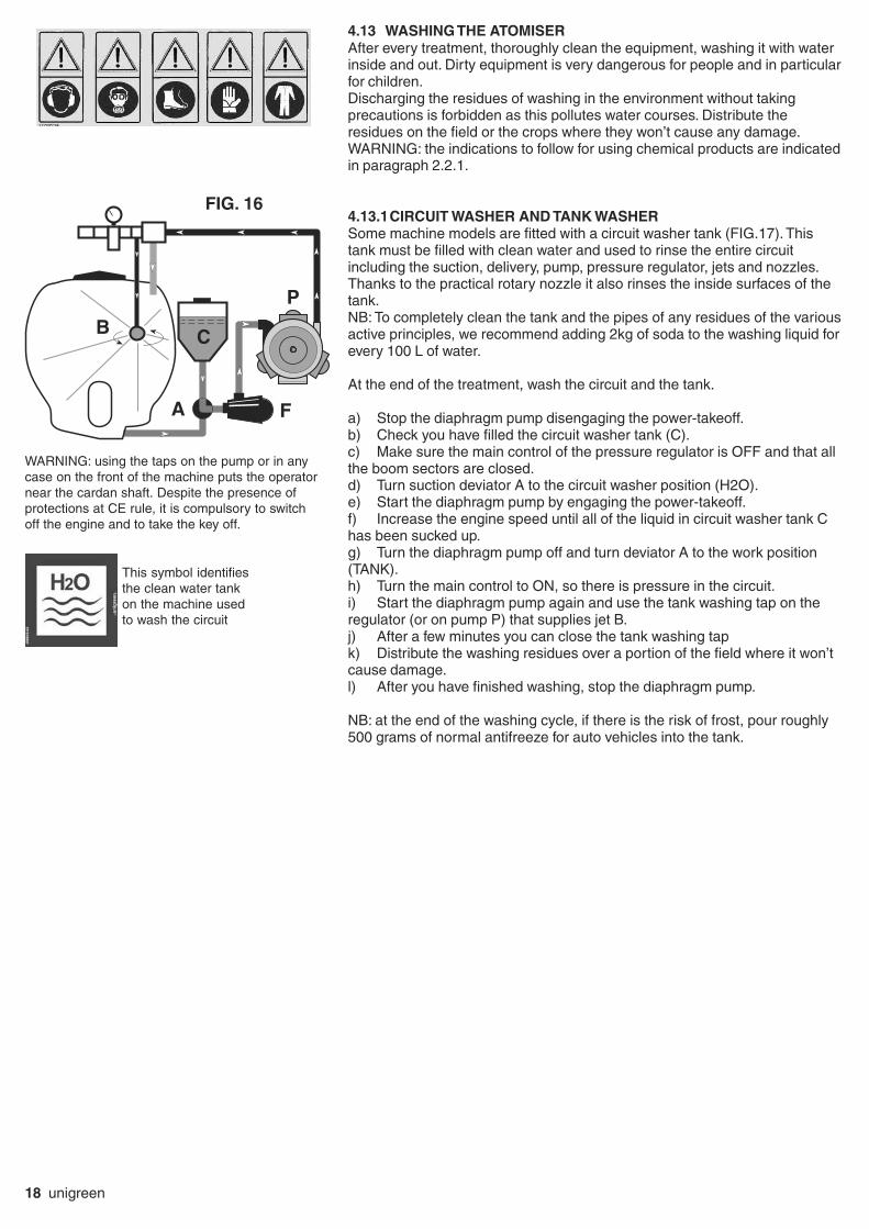
4.13 WASHING THE ATOMISER
After every treatment, thoroughly clean the equipment, washing it with waterinside and out. Dirty equipment is very dangerous for people and in particularfor children.Discharging the residues of washing in the environment without takingprecautions is forbidden as this pollutes water courses. Distribute theresidues on the field or the crops where they won’t cause any damage.WARNING: the indications to follow for using chemical products are indicatedin paragraph 2.2.1.
4.13.1CIRCUIT WASHER AND TANK WASHER
Some machine models are fitted with a circuit washer tank (FIG.17). Thistank must be filled with clean water and used to rinse the entire circuitincluding the suction, delivery, pump, pressure regulator, jets and nozzles.Thanks to the practical rotary nozzle it also rinses the inside surfaces of thetank.NB: To completely clean the tank and the pipes of any residues of the variousactive principles, we recommend adding 2kg of soda to the washing liquid forevery 100 L of water.
At the end of the treatment, wash the circuit and the tank.
a) Stop the diaphragm pump disengaging the power-takeoff.b) Check you have filled the circuit washer tank (C).c) Make sure the main control of the pressure regulator is OFF and that allthe boom sectors are closed.d) Turn suction deviator A to the circuit washer position (H2O).e) Start the diaphragm pump by engaging the power-takeoff.f) Increase the engine speed until all of the liquid in circuit washer tank Chas been sucked up.g) Turn the diaphragm pump off and turn deviator A to the work position(TANK).h) Turn the main control to ON, so there is pressure in the circuit.i) Start the diaphragm pump again and use the tank washing tap on theregulator (or on pump P) that supplies jet B.j) After a few minutes you can close the tank washing tapk) Distribute the washing residues over a portion of the field where it won’tcause damage.l) After you have finished washing, stop the diaphragm pump.
NB: at the end of the washing cycle, if there is the risk of frost, pour roughly500 grams of normal antifreeze for auto vehicles into the tank.
FIG. 16
A
BC
F
P
This symbol identifiesthe clean water tankon the machine usedto wash the circuit
WARNING: using the taps on the pump or in anycase on the front of the machine puts the operatornear the cardan shaft. Despite the presence ofprotections at CE rule, it is compulsory to switchoff the engine and to take the key off.

unigreen 19
5 BLOWER GROUP
All the mistblowers have a high speed fan rotor. You must take great
care and beware of the effects that this can provoke: such as the
aspiration and projection of foreign bodies which, although of a small
size, can be very dangerous especially for the eyes and face.
5.1 MULTIPLIER - FAN UNIT
The Airdrop range is fitted with two versions of a Ø500 centrifugal fan: STD(max absorption 30 HP) and XP (max 50 HP).The transmission of the drive from the pump to the fan is done through amultiplier with one or two gears, plus neutral.Normally the rotation speed of the fan is 3240 RPM in first gear and 3620RPM in second in the 2-speed multiplier (multiplied ratios 1:6 - 1:6.7) with thepower takeoff running at 540 RPM.You can change from one gear to the next with the lever on the multiplier,made accessible through the opening on the side in the rear left part of themachine or at a distance on the right side. The lever has 2 or 3 positionsdepending on the number of gears and the central position is neutral (to useonly the pump without the fan).
WARNING: the gear change lever must only be used with the power-takeoffdisengaged and the fan stopped. If it is difficult to engage, turn the cardanshaft slightly by hand to find the right position of the lever (make sure thetractor is turned off).
For the maintenance of the multiplier (see point "Multiplier Lubrication"
5.5 CLUTCH
Fans have a centrifugal type clutch that makes it possible to engage the fanrotor gradually.This prevents jerky starts, due to the inertia of the fan rotor, which can have anegative effect on the transmission.For the centrifugal clutch to work properly the speed of the power-takeoffmustn’t be less than 450 rpm, especially if you are using the first gear of themultiplier.Generally clutches with shoes/plates made of sintered material with a highcoefficient of friction are fitted, on some low power models rubber clutchesmay be fitted.
WARNING! As there is a high multiplication ratio, the fan must be startedgradually. Suddenly engaging the power-takeoff clutch (at high speed) candamage the gears.
Ø500 Nylon impeller with sinterized expansionclutch.
Ø500 fan with multiplier, 2-speed plusneutral.
WORK TEMPERATURE
Heat is generated by the friction between thevarious moving components and on the basisof the power transmitted. The temperatureof the multiplier or disengaging box dependson the capacity to dissipate heat to thesurrounding environment and therefore thesurfaces involved in the heat exchange andthe environmental conditions.The specifications refer to environmentalconditions with a temperature between-10° +50°C (14°C -122°F).The working temperature limit of the boxis 90°C (200°F) established to prevent theageing of the seals and guarantee a sufficientviscosity of the oil. The heat makes the air inthe box expand and therefore increases thepressure inside. The correct use of the oilseals is guaranteed up to an internal pressureof 0.5 bar. Boxes designed to be used forparticularly heavy duty work are equippedwith a breather cap that can be fittedon any cast iron box on request.

20 unigreen
5.3 DISTRIBUTOR ACCESSORIES
Various configurations of accessories or distributors are fitted to the outletof the fans. At present these are:Polipo - Super Spalliera - RV GDC - VLX for espalier- FXL "up and over"boom for espalier.WARNING: for all adjustments, always observe the safety indications in thechapters relevant to maintenance and repair of this manual, as well asparagraph 2.3.1 relevant to the use of chemical products.
5.3.1 POLIPO FOR ESPALIER
Tangential flow accessory that brings the diffusers closer to the walls totreat, for targeted and localised interventions. The vertical construction putsthe distributors parallel with the walls of the vegetation, guaranteeing auniform treatment with limited absorption.Versions with 4 or 5 distributors per side are available to choose from onthe basis of the height of the row.The height of the arms can be adjusted by hand and the distributors can beinclined to direct the chemical product in the best way for the configurationof the vegetation. All the adjustments are made by hand using knobs andscrews.When treating particularly wide rows (up to 4 m) OPTIONAL extendablearms are available.The "POLIPO" accessory is used with STD version fans.
5.3.2 SUPER SPALLIERA FOR ESPALIER
With this accessory you can treat particular espaliers with thickvegetation. It is especially indicated where you need to pass beyond therows, using a lot of air and power.The variable diffusers let you direct the product in relation to therequirements of the vegetation. All of the adjustments are done by handusing the knobs and screws.The SUPER SPALLIERA accessory is used with XP fans.
5.3.3 RV BOOM FOR GDC
This boom has lateral diffusers (variable and moveable) and two toparms with hydraulic or manual adjustment, so the jets can bedirected onto the vegetation to be treated.In the bottom part there are two adjustable, telescopic distributorsfor GDC treatment.The height of the structure can be adjusted by hand for differenttypes of vegetation.The RV-GDC accessory is used with XP fans.
SUPER SPALLIERA
POLIPO SPALLIERA
RV per GDC

unigreen 21
5.3.4 VLX BOOM FOR ESPALIER
The VLX version is designed for the simultaneous treatment of two seriesof rows, and combines the lateral diffusers (variable and movable) withtwo upper extendable arms. This makes it possibleto move the distributors up to the external rows.The opening and extension of the boom arms iscontrolled by a sequential kinematic mechanismusing hydraulic cylindersOn request, the boom can be fitted with a liftingdevice that has an integrated hydraulic cylinder inthe frame.For instructions on opening the boom, see chapter5.4.The VLX accessory is used with XP version fans.
5.3.5 FXL "UP AND OVER" BOOM FOR ESPALIER
The FXL version is a boom built for passing over the rows, the verticaldrop of the distributors remains parallel with the plant walls, guaranteeinguniform treatment.The opening and height regulation of the arms(variable geometry) are controlled by hydrauliccylinders.The extension in width is manually regulated toadapt the boom to the distance of the plants.The external arms are fitted with safety joints toavoid damage. In the event of a collision thevertical drop folds to overcome the obstacle andreturns to its normal working positionautomatically. In any case the operator should tryto avoid knocking against objects as this coulddamage both the boom and the obstacle in time;all the more so if the two elements get stuck.The boom comes complete with a lifting devicethat has a cylinder hydraulic integrated in theframe. For instructions on opening the bar, seechapter 5.4.The FXL accessory is used with XP version fans.
5.4 HYDRAULICS
The RV, VLX and FXL model distributor accessories have hydraulics thatcan be controlled by the operator directly from the seat in the cab.Check that no one and nothing is in the area where the booms will open;particular attention should be paid to the presence of any electric powerlines.
The hydraulic plant can be fed from the hydraulic pump of the tractor.The hydraulics can be controlled using the lever of the tractor (RV andVLX) or a hydraulic distributor with mechanical or electro-hydrauliccommand with switches in the cabin (FXL).- All of the controls on both versions are sustained action controls andeach lever or switch has a pictogram of the relevant operation it controls.
WARNING: with hydraulic booms, don’t stand in the range of action of themachine.Pay attention to the integrity and efficiency of the hydraulic componentsand in particular to the pipes to prevent the risk of bursting.Do a full check on the pipes and components at least once a year, werecommend replacing hydraulic pipes every 3-4 years.
VLX SPALLIERA
FXL SPALLIERA

22 unigreen
5.4.1 OIL FEED FROM TRACTOR
Consult the use and maintenance manual of the tractor.Connect the delivery and discharge quick-fit coupling to the respectiveconnections, respecting the direction of flow.= On booms that have a direct connection to the quick-fit couplings, eachpair of couplings feeds a cylinder.= For booms equipped with EDR electro-deviators, follow the diagram ofthe couplings supplied.= For manual or electric distributors (Elettroil), the distributor inlet pipe isconnected to the aluminium flow separator valve next to the distributor (seephoto).The flow separator must be adjusted correctly so it send less than 4-5 L/1° tothe distributor.To prevent the cylinders moving at a dangerous speed, adjust the relevantchokes near the cylinders. If the registration ring nuts aren’t visible then fixedchokes are fitted. The chokes are fitted on the discharge line of themovement to slow.Any impurities in the oil could block the chokes and as a consequence blockthe cylinder; remove the dirt if necessary.The maximum pressure valves of the distributors are regulated to a pressureof around 150 bar.To prevent the excessive heating of the oil we recommend supplying thedistributor of the sprayer only when the cylinders are being used.We recommend having qualified personnel do any adjustments.
5.4.2 CONTROLS FOR HYDRAULIC ACCESSORIES
Normally the hydraulic equipment of this series is equipped with cylindersdriven directly by quick-fit couplings (1 pair for each cylinder):
RV: 2 pairs of couplings control the 2 right and left independent cylinders forinclining the arms.
VL: 2 pairs of couplings control the 2 right and left independent cylinders foropening the arms.
VLX: 3 pairs of quick-fit couplings for the 2 right and left independentcylinders for opening the arms + 1 lifting cylinder.For tractors with only 2 pairs of couplings an electro-deviator with apushbutton panel can be supplied on request, in this case you will only haveto use 1 pair of couplings to lift and 1 pair to connect the electro-deviator withwhich you can alternatively control the right or left arm through switch HD.For the maintenance of the arms (cleaning nozzles and anything else) theVLX accessory is equipped with an auxiliary inclination cylinder, which lets
you lower the arms to the working height.The auxiliary cylinder is activated by a pair of supplementary quick-fitcouplings, to lower the boom momentarily connect the two couplings (ifthe tractor doesn't have a free connection disconnect any one of the pairsused for work).
FXF - FXL: 2 pairs of quick-fit couplings connected to the Elettroil modeldistributor.Opening the "Up and Over" boom is the only operation that involves anobligatory sequence of operations:- activate the lifting (button H1) to lift the boom off the lateral supports.- open the right and left arms using buttons H3 and H6.
- if necessary extend the arms using buttons H4 and H5, to adapt them tothe distance between the rows.- if necessary adjust the independent inclination (variable geometry) of thearms according to the requirements of the ground (buttons H2 and H7).To close the boom, repeat the operations in the reverse sequence.During work, both the lifting and the variable geometry can be used to avoidobstacles. In any case make sure you avoid any cables and electricity lines.
HD
H1 H2 H4H3 H5 H6 H7
Elettroil connection to quick-fit couplings of thetractor
OIL CONTROL BOX for FXL
OIL CONTROL BOX for VLX

unigreen 23
6 SPRAYING
WARNING: the indications to follow for using chemical products are indicatedin paragraph 2.2.1.
6.1 DESCRIPTION OF THE DIFFUSERS
The distributor accessories of the TurboTeuton range are equipped withvariable diffusers (FIG. 18) so you can direct the airflow (and consequentlythe treatment) onto the vegetation to treat on the basis of your needs.According to the configuration of the accessory the diffusers have outletmouths with different shapes and sections. The diffusers can be equippedwith a double series of non-drip jets on request (FIG. 19).
6.1 DESCRIPTION OF TYPE OF JETS
Various types of jets are fitted; with a single or double head.Generally they have a non-drip diaphragm and are made out of brass,suitable for pressures up to 40 bar, some models are nickel plated.The jets can be equipped with different types of nozzles, changing thelocking ringnuts. The jets used normally have high volume, Ø18, ceramicplates and low volume conical nozzles (Albuz ATR or Teejet TXB). The jetsfor cannons have a jet holder with adjustable delivery and spray that hashigh volume, ceramic plates, Ø15 instead of 18.
All the jets normally used have three positions (FIG. 21):a) spray - if the nozzle is pointing outwards, away from the blower group,parallel with the non-drip valveb) closed - if the nozzle is at 90° with respect to the non-drip valve or, forthe single jet if it is facing inwards towards the blower groupc) nozzle second spray - when these are pointing towards the outside ofthe blower group parallel with the non-drip valve.
6.2 DESCRIPTION OF TYPE OF NOZZLES
The nozzles are extremely important to obtain a correct distribution on thevegetation to be treated. Poor quality or worn nozzles have a tendency tocreate unevenly treated strips.The nozzles are produced in various sizes, to work with a precise pressurerange, to create certain types of larger or smaller drops; using nozzles for apurpose they are not envisaged for prejudices the precision and duration ofthe nozzles.
6.2.2 LOW VOLUME CONICAL NOZZLES (150-500L/HA)
Made of two ceramic pieces with colour-coded plastic inserts, they areavailable in various sizes identified by the colour (see table 3 page 34).They have been specifically designed to obtain a large number of smalldrops with strong turbulence even at low pressures (2-3 bar). This turbulencemakes them suitable for penetrating luxuriant vegetation and so they aresuitable for fungicides and insecticides. The nozzles of the TR Lechler andTXA Teejet series are in this category.
6.2.3 ANTI-DRIFT NOZZLES
Specific anti-drift nozzles are available from Unigreen. The maincharacteristic of these nozzles is that they eliminate the fog effect caused bythe presence of drops that are too small and are particularly sensitive todrifting. For further information please contact Unigreen for the relevantinstruction handbook.
FIG. 19
FIG. 20
FIG. 18
Open nozzle (ON) Closed nozzle (OFF)

24 unigreen
CB
A
FIG. 22
6.3 CALIBRATING TURBO TEUTON
The tables on pages 28-36 let you easily calculate the distribution in litres/hectare of the mistblowers with the standard fittings, proceeding as indicatedbelow:a) Choose the table relevant to the blower group of the mistblower in question(the main reference is the number of jets)b) Find the distance between the rows of the vegetation and the diameter ofthe nozzles used (ceramic plates, TR or TXA).c) In the horizontal strip, choose the working speed and the distribution inlitres/hectare and on the vertical scale find the pressure to use.d) Adjust the pressure to obtain the treatment required.If the distance between the rows is different from that in the table you caneasily calculate the distribution in proportion: for example with a distancebetween the rows of 8 m, divide the figure for the litres/hectare of the distancebetween the 4 m rows by half, with a distance between the rows of 2.5 mdouble the figure for the distance between the 5 m rows.The last line of the table indicates the overall delivery of the fan.If the mistblower is fitted with non-standard nozzles, the spraying tables of thesingle nozzles per mistblower are on page 34.To calculate the distribution in litres/hectare, use the following formula:
Vd = 600 x Q
I x V where: Vd = volume to distribute (L/ha)Q = sum of the nozzles delivery (L/min)I = distance between the rows (m)V = tractor speed (Km/h)
EXAMPLE:Distance between the rows: 5 m
Speed: 6 Km. / h
Working air pressure 30 barFan Ø 800 with 14 standard, high volume nozzles (Ø 1.0)
Q total delivery of the nozzles (Tab. 1 page 34) 2.96x14= 41.44 L/min
Vd = 600 x 41.44 = 829 L/ha 5 x 6
N.B. : Depending on the season the vegetation may be more or less luxuriant;bear this in mind before starting the treatment. If the plants don’t have muchfoliage you should diminish the quantity of litres per hectare using lowerpressures or closing one or more jets of the fan.
7 HAND LANCES
When using hand lances bear in mind the following notes:= Don’t direct the jet of liquid towards electric power lines or zones wherethere is electrical current, houses or where people might pass.= Don’t point the jet at people or animals.The jet can cause serious injuries simply due to the mechanical force of theliquid under pressure.= Never block the spraying lever of the lance in an open position because ifthe lance falls it will be uncontrollable.= At the end of work after you have stopped the pump, make sure that anyresidual pressure in the pipes under pressure has been drained to avoidunexpected jets when putting the lance away. There are various types oflances; with a lever, mitra spray gun and pistol grip.For further information please refer to the handbook in the package.The lever lance is controlled by opening lever A which, depending on howmuch it’s pressed, produces a conical spray or direct jet. The standard nozzleis Ø 1.5The mitra spray gun can produce a direct jet or a conical spray and the typeof spray is selected by pushing lever B forwards or backwards. Use lever C toopen the jet. The standard nozzle is Ø 2.5Replacement nozzles are available for all of the lances and the capacities areindicated in the tables TAB.4 and TAB.5 ( page 37).
N.B. to calculate the different ranges it issufficient to multiply the value lt/hectare by thecorresponding width indicated in the table anddivide it by the new width.
Example-In the table: 907lt/ha with row distance 3m.
907x3 = 971 Lt/ha with row distance 2,8m 2,8

unigreen 25
8 MAINTENANCE
All of the maintenance operations and repairs must be carried out with the ma-chine and cardan shaft stopped and the tank and circuit clean of any residuesof chemical products.The maintenance of the mistblower is essential for maintaining a high level ofsafety. Also consult the single handbooks of the main components of themistblower.WARNING: the indications to follow for using chemical products are indicatedin paragraph 2.2.1.
8.1 PROGRAMMED MAINTENANCE
(TAB. N° 7, page 36)We recommend using a table of programmed maintenance to follow in time tokeep the mistblower in an efficient working condition.For major and important maintenance jobs we recommend using the normalUNIGREEN assistance service available from your reseller, (if necessary)replacing parts using original spare parts only.
8.2 ROUTINE MAINTENANCE
= After every treatment wash the inside of the tank and the entire circuit asindicated in paragraph 4.13= Periodically check that the suction and delivery filters are clean= Check the oil level in the volumetric compensator of the pump= The use of chemical products that are particularly damaging for a nitrilerubber mix can cause the diaphragm to break before time.In these conditions check the state of the components more often. There arediaphragms made of special materials (viton and desmopan) that are availableon request.= When doing treatments with copper hydroxide you should take great careto thoroughly clean the system, washing it after each treatment becausehydroxides attack parts that aren’t painted or protected by hot galvanising.To prevent chemical attacks we recommend spraying transparent paint on theparts that are most exposed to the product and equipping the mistblower withstainless steel pressure gauges.
8.2.1 CLEANING THE NOZZLES
Check the state of wear of the nozzles and replace them when the delivery isover 30-35% of the theoretical level.If you notice even a partial blockage of a nozzle proceed as follows:- drain the pressure and stop the machine- dismantle the screw or bayonet ringnuts holding the nozzles- clean with a small brush or compressed air, don’t use nails, punches or
bradawls
- reassemble the nozzles and the ringnuts, replacing the filters and seals.8.2.2 LUBRICATION
The moving mechanical components must be lubricated to prevent wear andoverheating. This lubrication can be done with grease or oil: oil allowssignificantly higher speeds, in general grease is used to lubricate bearings witha vertical or inclined axis as it stays in the zone for longer.
8.2.3 MULTIPLIER LUBRICATION
The multiplier and disengaging boxes are normally lubricated in an “oil bath”, inspecial cases NLGI n.0 grease is used. The viscosity is an essentialcharacteristic of a lubricant oil and this is indicated by the SAE (SOCIETY OFAUTO-MOTIVE ENGINEERS) classification of the oils for gearboxes anddifferentials. Special additives improve the capacity of the oil to maintain alubricant film also at high pressures and temperatures. We recommendedusing SAE 90 oil for the multiplier and disengaging boxes. The quantity of oil isestablished by the level cap. A greater quantity of oil doesn’t improve theconditions of lubrication and can cause overheating in the box. Changing the oilprotects the parts from the dangers associated with wear and the presence ofmetallic particles that can be present, especially in the first period of use. Werecommend replacing the oil after the first 50 working hours and thensubsequently every 500 hours.The quantity of oil needed is indicated on the sticker near the multiplier (FIG.23)WARNING: waste oil must not be dispersed in the environment, to dispo-
se of waste oil see paragraph 8.7.1.
FIG. 23

26 unigreen
8.3 EXTRAORDINARY MAINTENANCE
At the end of a season of intense use, or every two years of normal use, it is a good idea tohave a specialised service technician perform a general check on the machine.
8.4 REPAIRS
We recommend having the normal UNIGREEN assistance service available from our resellerperform any repairs or contact a specialised workshop. During all of the repairs, in particularwhen welding, the machine and the circuit must be clean of any residues of chemicalproduct.If the machine has to be lifted (for example to change a wheel) follow the instructions in point4.3 of the present handbook.Also make sure the machine is stopped, connected to the tractor, and use the relevantchocks to block the wheel still on the ground.If you use a jack (manual or hydraulic) make sure you use a jack that is suitable for the frameso it can’t slip and put it in the right position. The jack must be placed under the main frameof the machine near the wheel to change. Make sure the ground is compact: if necessary usewooden beams or other sufficiently resistant material to broaden the supporting base of thejack.
8.5 STORAGE IN A WAREHOUSE AND TRANSPORTATION
The sprayer must be kept in a closed place away from excessive humidity and protectedfrom frost. Especially if electrical pressure regulators, electrical motors, a spraying computeror similar components are fitted.Before storing the machine, after you have washed it, apply a light coat of oil.If the temperature might drop to below zero, drain any residual liquid or add roughly 0.5 L ofnormal antifreeze for auto vehicles.To transport the machine follow the instructions in point 4.3 of the present handbook.
8.6 PUTTING BACK INTO SERVICE AFTER WINTER LAYUP
Before using the machine again after a long period of inactivity you should perform somegeneral checks, following the instructions in point 4.2 and drain any antifreeze.Never start the shaft of the pump if you think there may by ice inside. To check this,
make sure you can turn the shaft by hand without connecting it to the tractor.
After you have connected the machine to the tractor (see point 4.4) following the instructionsin the present user’s handbook and in the enclosures of the pump, pressure regulator andaccessories.
8.7 DEMOLITION AND DISPOSAL
When the sprayer will be put out of service you should wash it with great care to remove anyresidues of chemical product, follow the instructions in point 4.13 of the present handbook.ATTENTION: It is necessary to adopt appropriate Individual Protection Devices inmanipulating waste.The disposal of waste deriving from the demolition of the machine must be carried outrespecting the environment, avoiding soil, air and water pollution.Local legislation in force in the matter must be respected in any case.Remember that waste is understood as any substance or object that enters into thecategories shown in attachment A in part IV of Legislative Decree 152/2006, that the holderhas destroyed, has decided or is obliged to destroy.Waste deriving from the demolition of the machine is classifiable as special waste.
8.7.1 MATERIALS FOR DEMOLITION
Non-dangerous special waste is that which can be recovered, according to the February1998 Ministerial Decree:· Iron, aluminium, stainless steel and copper materials· Plastic materials· Electronic cards· Hydraulic oil· Electrical plant
8.7.2 INDICATIONS FOR A SUITABLE TREATMENT OF WASTE
The Correct management of special waste envisages:- stocking in suitable places, avoiding mixing dangerous waste with the non-dangerous.- ensuring that authorised carriers and receivers carry out its transport and disposal/recovery.

unigreen 27
Commonly used spare parts
Transport of one's waste to authorised collection centres is allowed exclusively if you are enrolled in the Environmental Manage-ment Register.
8.7.3 ELECTRICAL AND ELECTRONIC APPARATUS WASTE (EEAW)
The Italian government has adopted the European Parliament directives in the matter of the disposal of electrical and electronicwaste (EEAW) (2002/95/CE and 2003/108/CE Directives) with Legislative Decree n° 151,July 25 2005).The measures: in particular, the decree established measures and procedures aimed at:a) forestalling the production of EEAW;b) promoting the re-use, recycling and other forms of EEAW recovery, in order to reduce the quantity to send for disposal;c) improving, in terms of the environment, the actions of the subjects who participate in the life-cycle of these apparatuses(producers, distributors, consumers and operators directly involved in the treatment of EEAW);d) reducing the use of dangerous substances in electrical and electronic apparatus.
The decree imposes the limitation and elimination of several substances present in EEAW: lead, mercury, cadmium, chrome,hexavalent chrome, polybrominated biphenyl, polybrominated diphenyl and polybrominated diphenyl ethers.The machine has been designed and created in conformity with this directive. Follow the indications shown below.The symbol to the side, showing a barred garbage can on wheels, indicates the separate collection of the electrical andelectronic apparatuses of the machine.
The user of the present machine can contact the collection centres instituted by the Local Authorities or the UNIGREENCompany directly, or request withdrawal by the dealer, in order to carry out correct disposal of the waste.
part description code
single Ø18 non-drip jet for mistblower withdiaphragm (1/4" mount) without nozzles 1224/0194F
double Ø18 non-drip jet for mistblower withdiaphragm (1/4" mount) without nozzles 1224/0195F
double 15 + Ø18 non-drip jet Ø for cannon withdiaphragm (1/4" mount) without nozzles 1224/0199F
ceramic conical nozzle Ø0,8 3400/0394Fhigh volume Ø1,0 3400/0395Ffor Ø18 mistblower jet Ø1,2 3400/0396F
Ø1,5 3400/0397FØ1,8 3400/0398FØ2,0 3400/0399F
diffuser Ø18 mm. closed B1606.0011for mistblower jet Ø1,0 B1606.0012
Ø1,2 B1606.0013Ø1,5 B1606.0014Ø1,8 B1606.0015
filter for Ø18 jet holes Ø 0,8 1002/0110F
Ceramic, conical nozzle kit, Nozzle Ø0,8 Dif. Ø1,0 Filter Ø0,8 3400/0400Ffilter diffuser and seal Nozzle Ø1,0 Dif. Ø1,0 Filter Ø0,8 3400/0401F
for Ø18 mm jet Nozzle Ø1,2 Dif. Ø1,2 Filter Ø1,0 3400/0402FNozzle Ø1,5 Dif. Ø1,5 Filter Ø1,0 3400/0403FNozzle Ø1,8 Dif. Ø1,8 Filter Ø1,0 3400/0404FNozzle Ø2,0 Dif. Ø1,8 Filter Ø1,0 3400/0405F
Clamp kit for fixing G1/4" jets on Ø1/2" booms 1805/0034F
Clamp kit for fixing G1/4" jets on Ø1/2" booms+ M8 F thread 1805/0050F
TXA80-005 Lilac 3400/0611FISO nozzle TXA80-067 Olive 3400/0612F
ceramic conical TXA80-01 Orange 3400/0613Fwith slinger TXA80-015 Green 3400/0614F
+ OR TXA80-02 Yellow 3400/0615FTXA80-03 Blue 3400/0616FTXA80-04 Red 3400/0617F
Te
eje
t

28 unigreen
unigreen spa Tabella erogazione in Litri/ettaro Turbo Teuton 16 getti
Lt./ha spreading rate table for Turbo Teuton 16 NOZZLES
ISO OLIVA -Olive ISO ARANCIO -Orange Larghezza di lavoro
PRESSIONE bar 5 7 10 12 15 18 20 5 7 10 12 15 18 20 working width
3,5 533 629 743 819 914 1010 1067 781 914 1095 1190 1343 1467 15434 467 550 650 717 800 883 933 683 800 958 1042 1175 1283 13505 373 440 520 573 640 707 747 547 640 767 833 940 1027 1080 1,86 311 367 433 478 533 589 622 456 533 639 694 783 856 9007 267 314 371 410 457 505 533 390 457 548 595 671 733 771 1,8 m.
3,5 480 566 669 737 823 909 960 703 823 986 1071 1209 1320 13894 420 495 585 645 720 795 840 615 720 863 938 1058 1155 12155 336 396 468 516 576 636 672 492 576 690 750 846 924 972 26 280 330 390 430 480 530 560 410 480 575 625 705 770 8107 240 283 334 369 411 454 480 351 411 493 536 604 660 694 2 m.
3,5 384 453 535 590 658 727 768 562 658 789 857 967 1056 11114 336 396 468 516 576 636 672 492 576 690 750 846 924 9725 269 317 374 413 461 509 538 394 461 552 600 677 739 778 2,56 224 264 312 344 384 424 448 328 384 460 500 564 616 6487 192 226 267 295 329 363 384 281 329 394 429 483 528 555 2,5 m.
Litri/min. 5,6 6,6 7,8 8,6 9,6 10,6 11,2 8,2 9,6 11,5 12,5 14,1 15,4 16,2 Tab. 3215/0000F
ug. sing. 0,35 0,41 0,49 0,54 0,60 0,66 0,70 0,51 0,6 0,72 0,78 0,88 0,96 1,01
ISO 16 GETTI
Vel
ocità
Km
/hsp
eed
Litr
i/ha
Vel
ocità
Km
/hsp
eed
Vel
ocità
Km
/hsp
eed
Litr
i/ha
Litr
i/ha
unigreen spa Tabella erogazione in Litri/ettaro Turbo Teuton 8 getti
Lt./ha spreading rate table for Turbo Teuton 8 NOZZLES
ISO ARANCIO -Orange ISO GIALLO -Yellow Larghezza di lavoro
PRESSIONE bar 5 7 10 12 15 18 20 5 7 10 12 15 18 20 working width
3,5 390 457 552 590 667 733 771 771 905 1086 1190 1324 1448 15334 342 400 483 517 583 642 675 675 792 950 1042 1158 1267 13425 273 320 387 413 467 513 540 540 633 760 833 927 1013 1073 1,86 228 267 322 344 389 428 450 450 528 633 694 772 844 8947 195 229 276 295 333 367 386 386 452 543 595 662 724 767 1,8 m.
3,5 351 411 497 531 600 660 694 694 814 977 1071 1191 1303 13804 308 360 435 465 525 578 608 608 713 855 938 1043 1140 12085 246 288 348 372 420 462 486 486 570 684 750 834 912 966 26 205 240 290 310 350 385 405 405 475 570 625 695 760 8057 176 206 249 266 300 330 347 347 407 489 536 596 651 690 2 m.
3,5 281 329 398 425 480 528 555 555 651 782 857 953 1042 11044 246 288 348 372 420 462 486 486 570 684 750 834 912 9665 197 230 278 298 336 370 389 389 456 547 600 667 730 773 2,56 164 192 232 248 280 308 324 324 380 456 500 556 608 6447 141 165 199 213 240 264 278 278 326 391 429 477 521 552 2,5 m.
Litri/min. 4,1 4,8 5,8 6,2 7,0 7,7 8,1 8,1 9,5 11,4 12,5 13,9 15,2 16,1 Tab. 3215/0000F
ug. sing. 0,51 0,6 0,72 0,78 0,88 0,96 1,01 1,01 1,19 1,42 1,56 1,74 1,9 2,01
Litr
i/ha
Litr
i/ha
ISO 8 GETTI
Vel
ocità
Km
/hsp
eed
Litr
i/ha
Vel
ocità
Km
/hsp
eed
Vel
ocità
Km
/hsp
eed
TABLES FOR CALIBRATING POLIPO 4+4 (8 NOZZLES) NARROW ROWS
TurboTeuton CALIBRATING TABLES
N.B. to calculate the different ranges it is sufficient to multiply the value lt/hectare by the corresponding widthindicated in the table and divide it by the new width (see chapter 6.3, page 24).
TABLES FOR CALIBRATING POLIPO 4+4 (16 NOZZLES) NARROW ROWS

unigreen 29
unigreen spa Tabella erogazione in Litri/ettaro Turbo Teuton 16 getti
Lt./ha spreading rate table for Turbo Teuton 16 NOZZLES
ISO OLIVA -Olive ISO ARANCIO -Orange Larghezza di lavoro
PRESSIONE bar 5 7 10 12 15 18 20 5 7 10 12 15 18 20 working width
3,5 384 453 535 590 658 727 768 562 658 789 857 967 1056 11114 336 396 468 516 576 636 672 492 576 690 750 846 924 9725 269 317 374 413 461 509 538 394 461 552 600 677 739 778 2,56 224 264 312 344 384 424 448 328 384 460 500 564 616 6487 192 226 267 295 329 363 384 281 329 394 429 483 528 555 2,5 m.
3,5 320 377 446 491 549 606 640 469 549 657 714 806 880 9264 280 330 390 430 480 530 560 410 480 575 625 705 770 8105 224 264 312 344 384 424 448 328 384 460 500 564 616 648 36 187 220 260 287 320 353 373 273 320 383 417 470 513 5407 160 189 223 246 274 303 320 234 274 329 357 403 440 463 3 m.
3,5 240 283 334 369 411 454 480 351 411 493 536 604 660 6944 210 248 293 323 360 398 420 308 360 431 469 529 578 6085 168 198 234 258 288 318 336 246 288 345 375 423 462 486 46 140 165 195 215 240 265 280 205 240 288 313 353 385 4057 120 141 167 184 206 227 240 176 206 246 268 302 330 347 4 m.
Litri/min. 5,6 6,6 7,8 8,6 9,6 10,6 11,2 8,2 9,6 11,5 12,5 14,1 15,4 16,2 Tab. 3215/0000F
ug. sing. 0,35 0,41 0,49 0,54 0,60 0,66 0,70 0,51 0,6 0,72 0,78 0,88 0,96 1,01
Vel
ocità
Km
/hsp
eed
Litr
i/ha
Vel
ocità
Km
/hsp
eed
Vel
ocità
Km
/hsp
eed
Litr
i/ha
Litr
i/ha
ISO 16 GETTI
unigreen spa Tabella erogazione in Litri/ettaro Turbo Teuton 8 getti
Lt./ha spreading rate table for Turbo Teuton 8 NOZZLES
ISO ARANCIO -Orange ISO GIALLO -Yellow Larghezza di lavoro
PRESSIONE bar 5 7 10 12 15 18 20 5 7 10 12 15 18 20 working width
3,5 281 329 398 425 480 528 555 555 651 782 857 953 1042 11044 246 288 348 372 420 462 486 486 570 684 750 834 912 9665 197 230 278 298 336 370 389 389 456 547 600 667 730 773 2,56 164 192 232 248 280 308 324 324 380 456 500 556 608 6447 141 165 199 213 240 264 278 278 326 391 429 477 521 552 2,5 m.
3,5 234 274 331 354 400 440 463 463 543 651 714 794 869 9204 205 240 290 310 350 385 405 405 475 570 625 695 760 8055 164 192 232 248 280 308 324 324 380 456 500 556 608 644 36 137 160 193 207 233 257 270 270 317 380 417 463 507 5377 117 137 166 177 200 220 231 231 271 326 357 397 434 460 3 m.
3,5 176 206 249 266 300 330 347 347 407 489 536 596 651 6904 154 180 218 233 263 289 304 304 356 428 469 521 570 6045 123 144 174 186 210 231 243 243 285 342 375 417 456 483 46 103 120 145 155 175 193 203 203 238 285 313 348 380 4037 88 103 124 133 150 165 174 174 204 244 268 298 326 345 4 m.
Litri/min. 4,1 4,8 5,8 6,2 7,0 7,7 8,1 8,1 9,5 11,4 12,5 13,9 15,2 16,1 Tab. 3215/0000F
ug. sing. 0,51 0,6 0,72 0,78 0,88 0,96 1,01 1,01 1,19 1,42 1,56 1,74 1,9 2,01
ISO 8 GETTI
Vel
ocità
Km
/hsp
eed
Litr
i/ha
Vel
ocità
Km
/hsp
eed
Vel
ocità
Km
/hsp
eed
Litr
i/ha
Litr
i/ha
TABLES FOR CALIBRATING POLIPO 4+4 (8 NOZZLES) WIDE ROWS OPTIONAL
TurboTeuton CALIBRATING TABLES
N.B. to calculate the different ranges it is sufficient to multiply the value lt/hectare by the corresponding widthindicated in the table and divide it by the new width (see chapter 6.3, page 24).
TABLES FOR CALIBRATING POLIPO 4+4 (16 NOZZLES) WIDE ROWS OPTIONAL

30 unigreen
unigreen spa Tabella erogazione in Litri/ettaro Turbo Teuton 20 getti
Lt./ha spreading rate table for Turbo Teuton 20 NOZZLES
ISO OLIVA -Olive ISO ARANCIO -Orange Larghezza di lavoro
PRESSIONE bar 5 7 10 12 15 18 20 5 7 10 12 15 18 20 working width
3,5 667 781 933 1029 1143 1257 1333 971 1143 1371 1486 1676 1829 19244 583 683 817 900 1000 1100 1167 850 1000 1200 1300 1467 1600 16835 467 547 653 720 800 880 933 680 800 960 1040 1173 1280 1347 1,86 389 456 544 600 667 733 778 567 667 800 867 978 1067 11227 333 390 467 514 571 629 667 486 571 686 743 838 914 962 1,8 m.
3,5 600 703 840 926 1029 1131 1200 874 1029 1234 1337 1509 1646 17314 525 615 735 810 900 990 1050 765 900 1080 1170 1320 1440 15155 420 492 588 648 720 792 840 612 720 864 936 1056 1152 1212 26 350 410 490 540 600 660 700 510 600 720 780 880 960 10107 300 351 420 463 514 566 600 437 514 617 669 754 823 866 2 m.
3,5 480 562 672 741 823 905 960 699 823 987 1070 1207 1317 13854 420 492 588 648 720 792 840 612 720 864 936 1056 1152 12125 336 394 470 518 576 634 672 490 576 691 749 845 922 970 2,56 280 328 392 432 480 528 560 408 480 576 624 704 768 8087 240 281 336 370 411 453 480 350 411 494 535 603 658 693 2,5 m.
Litri/min. 7,0 8,2 9,8 10,8 12,0 13,2 14,0 10,2 12,0 14,4 15,6 17,6 19,2 20,2 Tab. 3215/0000F
ug. sing. 0,35 0,41 0,49 0,54 0,60 0,66 0,70 0,51 0,6 0,72 0,78 0,88 0,96 1,01
ISO 20 GETTI
Vel
ocità
Km
/hsp
eed
Litr
i/ha
Vel
ocità
Km
/hsp
eed
Vel
ocità
Km
/hsp
eed
Litr
i/ha
Litr
i/ha
unigreen spa Tabella erogazione in Litri/ettaro Turbo Teuton 10 getti
Lt./ha spreading rate table for Turbo Teuton 10 NOZZLES
ISO ARANCIO -Orange ISO GIALLO -Yellow Larghezza di lavoro
PRESSIONE bar 5 7 10 12 15 18 20 5 7 10 12 15 18 20 working width
3,5 486 571 686 743 838 914 962 962 1133 1352 1486 1657 1810 19144 425 500 600 650 733 800 842 842 992 1183 1300 1450 1583 16755 340 400 480 520 587 640 673 673 793 947 1040 1160 1267 1340 1,86 283 333 400 433 489 533 561 561 661 789 867 967 1056 11177 243 286 343 371 419 457 481 481 567 676 743 829 905 957 1,8 m.
3,5 437 514 617 669 754 823 866 866 1020 1217 1337 1491 1629 17234 383 450 540 585 660 720 758 758 893 1065 1170 1305 1425 15085 306 360 432 468 528 576 606 606 714 852 936 1044 1140 1206 26 255 300 360 390 440 480 505 505 595 710 780 870 950 10057 219 257 309 334 377 411 433 433 510 609 669 746 814 861 2 m.
3,5 350 411 494 535 603 658 693 693 816 974 1070 1193 1303 13784 306 360 432 468 528 576 606 606 714 852 936 1044 1140 12065 245 288 346 374 422 461 485 485 571 682 749 835 912 965 2,56 204 240 288 312 352 384 404 404 476 568 624 696 760 8047 175 206 247 267 302 329 346 346 408 487 535 597 651 689 2,5 m.
Litri/min. 5,1 6,0 7,2 7,8 8,8 9,6 10,1 10,1 11,9 14,2 15,6 17,4 19,0 20,1 Tab. 3215/0000F
ug. sing. 0,51 0,6 0,72 0,78 0,88 0,96 1,01 1,01 1,19 1,42 1,56 1,74 1,9 2,01
Vel
ocità
Km
/hsp
eed
Litr
i/ha
Vel
ocità
Km
/hsp
eed
Vel
ocità
Km
/hsp
eed
Litr
i/ha
Litr
i/ha
ISO 10 GETTI
TABLES FOR CALIBRATING POLIPO 5+5 (10 NOZZLES) NARROW ROWS
TurboTeuton CALIBRATING TABLES
TABLES FOR CALIBRATING POLIPO 5+5 (20 NOZZLES) NARROW ROWS
N.B. to calculate the different ranges it is sufficient to multiply the value lt/hectare by the corresponding widthindicated in the table and divide it by the new width (see chapter 6.3, page 24).

unigreen 31
unigreen spa Tabella erogazione in Litri/ettaro Turbo Teuton 20 getti
Lt./ha spreading rate table for Turbo Teuton 20 NOZZLES
ISO OLIVA -Olive ISO ARANCIO -Orange Larghezza di lavoro
PRESSIONE bar 5 7 10 12 15 18 20 5 7 10 12 15 18 20 working width
3,5 480 562 672 741 823 905 960 699 823 987 1070 1207 1317 13854 420 492 588 648 720 792 840 612 720 864 936 1056 1152 12125 336 394 470 518 576 634 672 490 576 691 749 845 922 970 2,56 280 328 392 432 480 528 560 408 480 576 624 704 768 8087 240 281 336 370 411 453 480 350 411 494 535 603 658 693 2,5 m.
3,5 400 469 560 617 686 754 800 583 686 823 891 1006 1097 11544 350 410 490 540 600 660 700 510 600 720 780 880 960 10105 280 328 392 432 480 528 560 408 480 576 624 704 768 808 36 233 273 327 360 400 440 467 340 400 480 520 587 640 6737 200 234 280 309 343 377 400 291 343 411 446 503 549 577 3 m.
3,5 300 351 420 463 514 566 600 437 514 617 669 754 823 8664 263 308 368 405 450 495 525 383 450 540 585 660 720 7585 210 246 294 324 360 396 420 306 360 432 468 528 576 606 46 175 205 245 270 300 330 350 255 300 360 390 440 480 5057 150 176 210 231 257 283 300 219 257 309 334 377 411 433 4 m.
Litri/min. 7,0 8,2 9,8 10,8 12,0 13,2 14,0 10,2 12,0 14,4 15,6 17,6 19,2 20,2 Tab. 3215/0000F
ug. sing. 0,35 0,41 0,49 0,54 0,60 0,66 0,70 0,51 0,6 0,72 0,78 0,88 0,96 1,01
Vel
ocità
Km
/hsp
eed
Litr
i/ha
Vel
ocità
Km
/hsp
eed
Vel
ocità
Km
/hsp
eed
Litr
i/ha
Litr
i/ha
ISO 20 GETTI
unigreen spa Tabella erogazione in Litri/ettaro Turbo Teuton 10 getti
Lt./ha spreading rate table for Turbo Teuton 10 NOZZLES
ISO ARANCIO -Orange ISO GIALLO -Yellow Larghezza di lavoro
PRESSIONE bar 5 7 10 12 15 18 20 5 7 10 12 15 18 20 working width
3,5 350 411 494 535 603 658 693 693 816 974 1070 1193 1303 13784 306 360 432 468 528 576 606 606 714 852 936 1044 1140 12065 245 288 346 374 422 461 485 485 571 682 749 835 912 965 2,56 204 240 288 312 352 384 404 404 476 568 624 696 760 8047 175 206 247 267 302 329 346 346 408 487 535 597 651 689 2,5 m.
3,5 291 343 411 446 503 549 577 577 680 811 891 994 1086 11494 255 300 360 390 440 480 505 505 595 710 780 870 950 10055 204 240 288 312 352 384 404 404 476 568 624 696 760 804 36 170 200 240 260 293 320 337 337 397 473 520 580 633 6707 146 171 206 223 251 274 289 289 340 406 446 497 543 574 3 m.
3,5 219 257 309 334 377 411 433 433 510 609 669 746 814 8614 191 225 270 293 330 360 379 379 446 533 585 653 713 7545 153 180 216 234 264 288 303 303 357 426 468 522 570 603 46 128 150 180 195 220 240 253 253 298 355 390 435 475 5037 109 129 154 167 189 206 216 216 255 304 334 373 407 431 4 m.
Litri/min. 5,1 6,0 7,2 7,8 8,8 9,6 10,1 10,1 11,9 14,2 15,6 17,4 19,0 20,1 Tab. 3215/0000F
ug. sing. 0,51 0,6 0,72 0,78 0,88 0,96 1,01 1,01 1,19 1,42 1,56 1,74 1,9 2,01
Litr
i/ha
Litr
i/ha
ISO 10 GETTI
Vel
ocità
Km
/hsp
eed
Litr
i/ha
Vel
ocità
Km
/hsp
eed
Vel
ocità
Km
/hsp
eed
TABLES FOR CALIBRATING POLIPO 5+5 (10 NOZZLES) WIDE ROWS OPTIONAL
TurboTeuton CALIBRATING TABLES
TABLES FOR CALIBRATING POLIPO 5+5 (20 NOZZLES) WIDE ROWS OPTIONAL
N.B. to calculate the different ranges it is sufficient to multiply the value lt/hectare by the corresponding widthindicated in the table and divide it by the new width (see chapter 6.3, page 24).

32 unigreen
unigreen spa Tabella erogazione in Litri/ettaro Turbo Teuton 20 getti
Lt./ha spreading rate table for Turbo Teuton 20 NOZZLES
ISO OLIVA -Olive ISO ARANCIO -Orange Larghezza di lavoro
PRESSIONE bar 5 7 10 12 15 18 20 5 7 10 12 15 18 20 working width
3,5 480 562 672 741 823 905 960 699 823 987 1070 1207 1317 13854 420 492 588 648 720 792 840 612 720 864 936 1056 1152 12125 336 394 470 518 576 634 672 490 576 691 749 845 922 970 2,56 280 328 392 432 480 528 560 408 480 576 624 704 768 8087 240 281 336 370 411 453 480 350 411 494 535 603 658 693 2,5 m.
3,5 400 469 560 617 686 754 800 583 686 823 891 1006 1097 11544 350 410 490 540 600 660 700 510 600 720 780 880 960 10105 280 328 392 432 480 528 560 408 480 576 624 704 768 808 36 233 273 327 360 400 440 467 340 400 480 520 587 640 6737 200 234 280 309 343 377 400 291 343 411 446 503 549 577 3 m.
3,5 300 351 420 463 514 566 600 437 514 617 669 754 823 8664 263 308 368 405 450 495 525 383 450 540 585 660 720 7585 210 246 294 324 360 396 420 306 360 432 468 528 576 606 46 175 205 245 270 300 330 350 255 300 360 390 440 480 5057 150 176 210 231 257 283 300 219 257 309 334 377 411 433 4 m.
Litri/min. 7,0 8,2 9,8 10,8 12,0 13,2 14,0 10,2 12,0 14,4 15,6 17,6 19,2 20,2 Tab. 3215/0000F
ug. sing. 0,35 0,41 0,49 0,54 0,60 0,66 0,70 0,51 0,6 0,72 0,78 0,88 0,96 1,01
Vel
ocità
Km
/hsp
eed
Litr
i/ha
Vel
ocità
Km
/hsp
eed
Vel
ocità
Km
/hsp
eed
Litr
i/ha
Litr
i/ha
ISO 20 GETTI
unigreen spa Tabella erogazione in Litri/ettaro Turbo Teuton 10 getti
Lt./ha spreading rate table for Turbo Teuton 10 NOZZLES
ISO ARANCIO -Orange ISO GIALLO -Yellow Larghezza di lavoro
PRESSIONE bar 5 7 10 12 15 18 20 5 7 10 12 15 18 20 working width
3,5 350 411 494 535 603 658 693 693 816 974 1070 1193 1303 13784 306 360 432 468 528 576 606 606 714 852 936 1044 1140 12065 245 288 346 374 422 461 485 485 571 682 749 835 912 965 2,56 204 240 288 312 352 384 404 404 476 568 624 696 760 8047 175 206 247 267 302 329 346 346 408 487 535 597 651 689 2,5 m.
3,5 291 343 411 446 503 549 577 577 680 811 891 994 1086 11494 255 300 360 390 440 480 505 505 595 710 780 870 950 10055 204 240 288 312 352 384 404 404 476 568 624 696 760 804 36 170 200 240 260 293 320 337 337 397 473 520 580 633 6707 146 171 206 223 251 274 289 289 340 406 446 497 543 574 3 m.
3,5 219 257 309 334 377 411 433 433 510 609 669 746 814 8614 191 225 270 293 330 360 379 379 446 533 585 653 713 7545 153 180 216 234 264 288 303 303 357 426 468 522 570 603 46 128 150 180 195 220 240 253 253 298 355 390 435 475 5037 109 129 154 167 189 206 216 216 255 304 334 373 407 431 4 m.
Litri/min. 5,1 6,0 7,2 7,8 8,8 9,6 10,1 10,1 11,9 14,2 15,6 17,4 19,0 20,1 Tab. 3215/0000F
ug. sing. 0,51 0,6 0,72 0,78 0,88 0,96 1,01 1,01 1,19 1,42 1,56 1,74 1,9 2,01
Litr
i/ha
Litr
i/ha
ISO 10 GETTI
Vel
ocità
Km
/hsp
eed
Litr
i/ha
Vel
ocità
Km
/hsp
eed
Vel
ocità
Km
/hsp
eed
TABLES FOR CALIBRATING SUPER SPALLIERA 4+4 (8 NOZZLES)
TurboTeuton CALIBRATING TABLES
TABLES FOR CALIBRATING SUPER SPALLIERA 4+4 (16 NOZZLES)
N.B. to calculate the different ranges it is sufficient to multiply the value lt/hectare by the corresponding widthindicated in the table and divide it by the new width (see chapter 6.3, page 24).

unigreen 33
unigreen spa Tabella erogazione in Litri/ettaro Turbo Teuton GDC 20 getti
Lt./ha spreading rate table for Turbo Teuton GDC 20 NOZZLES
ISO OLIVA -Olive ISO ARANCIO -Orange Larghezza di lavoro
PRESSIONE bar 5 7 10 12 15 18 20 5 7 10 12 15 18 20 working width
3,5 480 562 672 741 823 905 960 699 823 987 1070 1207 1317 13854 420 492 588 648 720 792 840 612 720 864 936 1056 1152 12125 336 394 470 518 576 634 672 490 576 691 749 845 922 970 2,56 280 328 392 432 480 528 560 408 480 576 624 704 768 8087 240 281 336 370 411 453 480 350 411 494 535 603 658 693 2,5 m.
3,5 400 469 560 617 686 754 800 583 686 823 891 1006 1097 11544 350 410 490 540 600 660 700 510 600 720 780 880 960 10105 280 328 392 432 480 528 560 408 480 576 624 704 768 808 36 233 273 327 360 400 440 467 340 400 480 520 587 640 6737 200 234 280 309 343 377 400 291 343 411 446 503 549 577 3 m.
3,5 300 351 420 463 514 566 600 437 514 617 669 754 823 8664 263 308 368 405 450 495 525 383 450 540 585 660 720 7585 210 246 294 324 360 396 420 306 360 432 468 528 576 606 46 175 205 245 270 300 330 350 255 300 360 390 440 480 5057 150 176 210 231 257 283 300 219 257 309 334 377 411 433 4 m.
Litri/min. 7,0 8,2 9,8 10,8 12,0 13,2 14,0 10,2 12,0 14,4 15,6 17,6 19,2 20,2 Tab. 3215/0000F
ug. sing. 0,35 0,41 0,49 0,54 0,60 0,66 0,70 0,51 0,6 0,72 0,78 0,88 0,96 1,01
Vel
ocità
Km
/hsp
eed
Litr
i/ha
Vel
ocità
Km
/hsp
eed
Vel
ocità
Km
/hsp
eed
Litr
i/ha
Litr
i/ha
ISO 20 GETTI
unigreen spa Tabella erogazione in Litri/ettaro Turbo Teuton GDC 10 getti
Lt./ha spreading rate table for Turbo Teuton GDC 10 NOZZLES
ISO ARANCIO -Orange ISO GIALLO -Yellow Larghezza di lavoro
PRESSIONE bar 5 7 10 12 15 18 20 5 7 10 12 15 18 20 working width
3,5 350 411 494 535 603 658 693 693 816 974 1070 1193 1303 13784 306 360 432 468 528 576 606 606 714 852 936 1044 1140 12065 245 288 346 374 422 461 485 485 571 682 749 835 912 965 2,56 204 240 288 312 352 384 404 404 476 568 624 696 760 8047 175 206 247 267 302 329 346 346 408 487 535 597 651 689 2,5 m.
3,5 291 343 411 446 503 549 577 577 680 811 891 994 1086 11494 255 300 360 390 440 480 505 505 595 710 780 870 950 10055 204 240 288 312 352 384 404 404 476 568 624 696 760 804 36 170 200 240 260 293 320 337 337 397 473 520 580 633 6707 146 171 206 223 251 274 289 289 340 406 446 497 543 574 3 m.
3,5 219 257 309 334 377 411 433 433 510 609 669 746 814 8614 191 225 270 293 330 360 379 379 446 533 585 653 713 7545 153 180 216 234 264 288 303 303 357 426 468 522 570 603 46 128 150 180 195 220 240 253 253 298 355 390 435 475 5037 109 129 154 167 189 206 216 216 255 304 334 373 407 431 4 m.
Litri/min. 5,1 6,0 7,2 7,8 8,8 9,6 10,1 10,1 11,9 14,2 15,6 17,4 19,0 20,1 Tab. 3215/0000F
ug. sing. 0,51 0,6 0,72 0,78 0,88 0,96 1,01 1,01 1,19 1,42 1,56 1,74 1,9 2,01
ISO 10 GETTI
Vel
ocità
Km
/hsp
eed
Litr
i/ha
Vel
ocità
Km
/hsp
eed
Vel
ocità
Km
/hsp
eed
Litr
i/ha
Litr
i/ha
TABLES FOR CALIBRATING RV-GDC 5+5 (10 NOZZLES)
TurboTeuton CALIBRATING TABLES
TABLES FOR CALIBRATING RV-GDC 5+5 (20 NOZZLES)
N.B. to calculate the different ranges it is sufficient to multiply the value lt/hectare by the corresponding widthindicated in the table and divide it by the new width (see chapter 6.3, page 24).

34 unigreen
unigreen spa Tabella erogazione in Litri/ettaro Turbo Teuton VLX 24 getti
Lt./ha spreading rate table for Turbo Teuton VLX 24 NOZZLES
ISO OLIVA -Olive ISO ARANCIO -Orange Larghezza di lavoro
PRESSIONE bar 5 7 10 12 15 18 20 5 7 10 12 15 18 20 working width
3,5 360 420 506 557 617 677 720 523 617 741 801 904 986 10374 315 368 443 488 540 593 630 458 540 649 701 791 863 9085 252 294 354 390 432 474 504 366 432 519 561 633 690 726 46 210 245 295 325 360 395 420 305 360 433 468 528 575 6057 180 210 253 279 309 339 360 261 309 371 401 452 493 519 2 + 2 m.
3,5 288 336 405 446 494 542 576 418 494 593 641 723 789 8304 252 294 354 390 432 474 504 366 432 519 561 633 690 7265 202 235 283 312 346 379 403 293 346 415 449 506 552 581 56 168 196 236 260 288 316 336 244 288 346 374 422 460 4847 144 168 202 223 247 271 288 209 247 297 321 362 394 415 2,5 + 2,5 m.
3,5 240 280 337 371 411 451 480 349 411 494 534 603 657 6914 210 245 295 325 360 395 420 305 360 433 468 528 575 6055 168 196 236 260 288 316 336 244 288 346 374 422 460 484 66 140 163 197 217 240 263 280 203 240 288 312 352 383 4037 120 140 169 186 206 226 240 174 206 247 267 301 329 346 3 + 3 m.
Litri/min. 8,4 9,8 11,8 13,0 14,4 15,8 16,8 12,2 14,4 17,3 18,7 21,1 23,0 24,2 Tab. 3215/0000F
ug. sing. 0,35 0,41 0,49 0,54 0,60 0,66 0,70 0,51 0,6 0,72 0,78 0,88 0,96 1,01
ISO 24 GETTI
Vel
ocità
Km
/hsp
eed
Litr
i/ha
Litr
i/ha
Vel
ocità
Km
/hsp
eed
Litr
i/ha
Vel
ocità
Km
/hsp
eed
unigreen spa Tabella erogazione in Litri/ettaro Turbo Teuton VLX 12 getti
Lt./ha spreading rate table for Turbo Teuton VLX 12 NOZZLES
ISO ARANCIO -Orange ISO GIALLO -Yellow Larghezza di lavoro
PRESSIONE bar 5 7 10 12 15 18 20 5 7 10 12 15 18 20 working width
3,5 261 309 369 403 454 493 519 519 613 729 801 896 977 10334 229 270 323 353 398 431 454 454 536 638 701 784 855 9045 183 216 258 282 318 345 363 363 429 510 561 627 684 723 46 153 180 215 235 265 288 303 303 358 425 468 523 570 6037 131 154 184 201 227 246 259 259 306 364 401 448 489 516 2 + 2 m.
3,5 209 247 295 322 363 394 415 415 490 583 641 717 782 8264 183 216 258 282 318 345 363 363 429 510 561 627 684 7235 146 173 206 226 254 276 290 290 343 408 449 502 547 578 56 122 144 172 188 212 230 242 242 286 340 374 418 456 4827 105 123 147 161 182 197 207 207 245 291 321 358 391 413 2,5 + 2,5 m.
3,5 174 206 246 269 303 329 346 346 409 486 534 597 651 6894 153 180 215 235 265 288 303 303 358 425 468 523 570 6035 122 144 172 188 212 230 242 242 286 340 374 418 456 482 66 102 120 143 157 177 192 202 202 238 283 312 348 380 4027 87 103 123 134 151 164 173 173 204 243 267 299 326 344 3 + 3 m.
Litri/min. 6,1 7,2 8,6 9,4 10,6 11,5 12,1 12,1 14,3 17,0 18,7 20,9 22,8 24,1 Tab. 3215/0000F
ug. sing. 0,51 0,6 0,72 0,78 0,88 0,96 1,01 1,01 1,19 1,42 1,56 1,74 1,9 2,01
ISO 12 GETTI
Vel
ocità
Km
/hsp
eed
Litr
i/ha
Vel
ocità
Km
/hsp
eed
Vel
ocità
Km
/hsp
eed
Litr
i/ha
Litr
i/ha
TABLES FOR CALIBRATING VLX 6+6 (12 NOZZLES)
TurboTeuton CALIBRATING TABLES
TABLES FOR CALIBRATING VLX 6+6 (24 NOZZLES)
N.B. to calculate the different ranges it is sufficient to multiply the value lt/hectare by the corresponding widthindicated in the table and divide it by the new width (see chapter 6.3, page 24).

unigreen 35
unigreen spa Tabella erogazione in Litri/ettaro Turbo Teuton FXL2 12 getti
Lt./ha spreading rate table for Turbo Teuton FXL2 12 NOZZLES
ISO ARANCIO -Orange ISO GIALLO -Yellow Larghezza di lavoro
PRESSIONE bar 5 7 10 12 15 18 20 5 7 10 12 15 18 20 working width
3,5 238 281 335 366 413 448 471 471 557 662 729 814 888 9394 208 245 293 320 361 392 413 413 488 580 638 713 777 8225 166 196 235 256 289 314 330 330 390 464 510 570 622 657 4,46 139 164 195 214 241 261 275 275 325 386 425 475 518 5487 119 140 168 183 206 224 236 236 279 331 364 407 444 469 2,2 + 2,2 m.
3,5 209 247 295 322 363 394 415 415 490 583 641 717 782 8264 183 216 258 282 318 345 363 363 429 510 561 627 684 7235 146 173 206 226 254 276 290 290 343 408 449 502 547 578 56 122 144 172 188 212 230 242 242 286 340 374 418 456 4827 105 123 147 161 182 197 207 207 245 291 321 358 391 413 2,5 + 2,5 m.
3,5 174 206 246 269 303 329 346 346 409 486 534 597 651 6894 153 180 215 235 265 288 303 303 358 425 468 523 570 6035 122 144 172 188 212 230 242 242 286 340 374 418 456 482 66 102 120 143 157 177 192 202 202 238 283 312 348 380 4027 87 103 123 134 151 164 173 173 204 243 267 299 326 344 3 + 3 m.
Litri/min. 6,1 7,2 8,6 9,4 10,6 11,5 12,1 12,1 14,3 17,0 18,7 20,9 22,8 24,1 Tab. 3215/0000F
ug. sing. 0,51 0,6 0,72 0,78 0,88 0,96 1,01 1,01 1,19 1,42 1,56 1,74 1,9 2,01
ISO 12 GETTI
Vel
ocità
Km
/hsp
eed
Litr
i/ha
Vel
ocità
Km
/hsp
eed
Vel
ocità
Km
/hsp
eed
Litr
i/ha
Litr
i/ha
TurboTeuton CALIBRATING TABLES
TABLES FOR CALIBRATING FXL2 ROWS 12 DIFFUSERS (24 NOZZLES)
unigreen spa Tabella erogazione in Litri/ettaro Turbo Teuton FXL2 24 getti
Lt./ha spreading rate table for Turbo Teuton FXL2 24 NOZZLES
ISO OLIVA -Olive ISO ARANCIO -Orange Larghezza di lavoro
PRESSIONE bar 5 7 10 12 15 18 20 5 7 10 12 15 18 20 working width
3,5 327 382 460 506 561 616 655 475 561 674 729 822 896 9434 286 334 402 443 491 539 573 416 491 590 638 719 784 8255 229 267 322 355 393 431 458 333 393 472 510 575 627 660 4,46 191 223 268 295 327 359 382 277 327 393 425 480 523 5507 164 191 230 253 281 308 327 238 281 337 364 411 448 471 2,2 + 2,2 m.
3,5 288 336 405 446 494 542 576 418 494 593 641 723 789 8304 252 294 354 390 432 474 504 366 432 519 561 633 690 7265 202 235 283 312 346 379 403 293 346 415 449 506 552 581 56 168 196 236 260 288 316 336 244 288 346 374 422 460 4847 144 168 202 223 247 271 288 209 247 297 321 362 394 415 2,5 + 2,5 m.
3,5 240 280 337 371 411 451 480 349 411 494 534 603 657 6914 210 245 295 325 360 395 420 305 360 433 468 528 575 6055 168 196 236 260 288 316 336 244 288 346 374 422 460 484 66 140 163 197 217 240 263 280 203 240 288 312 352 383 4037 120 140 169 186 206 226 240 174 206 247 267 301 329 346 3 + 3 m.
Litri/min. 8,4 9,8 11,8 13,0 14,4 15,8 16,8 12,2 14,4 17,3 18,7 21,1 23,0 24,2 Tab. 3215/0000F
ug. sing. 0,35 0,41 0,49 0,54 0,60 0,66 0,70 0,51 0,6 0,72 0,78 0,88 0,96 1,01
Vel
ocità
Km
/hsp
eed
Litr
i/ha
Vel
ocità
Km
/hsp
eed
ISO 24 GETTI
Vel
ocità
Km
/hsp
eed
Litr
i/ha
Litr
i/ha
TABLES FOR CALIBRATING FXL2 ROWS 12 DIFFUSERS (12 NOZZLES)
N.B. to calculate the different ranges it is sufficient to multiply the value lt/hectare by the corresponding widthindicated in the table and divide it by the new width (see chapter 6.3, page 24).

36 unigreen
unigreen spa Tabella erogazione in Litri/ettaro Turbo Teuton FXL3 36 getti
Lt./ha spreading rate table for Turbo Teuton FXL3 36 NOZZLES
ISO OLIVA -Olive ISO ARANCIO -Orange Larghezza di lavoro
PRESSIONE bar 5 7 10 12 15 18 20 5 7 10 12 15 18 20 working width
3,5 327 384 457 504 561 618 655 478 561 673 730 823 899 9454 286 336 400 441 491 541 573 418 491 589 639 720 786 8275 229 269 320 353 393 433 458 335 393 471 511 576 629 662 6,66 191 224 267 294 327 361 382 279 327 392 426 480 524 5527 164 192 229 252 281 309 327 239 281 336 365 412 449 473 2,2+2,2+2,2 m.
3,5 288 338 402 443 494 544 576 421 494 592 642 725 791 8324 252 296 352 388 432 476 504 368 432 518 562 634 692 7285 202 237 282 310 346 381 403 294 346 414 450 507 554 582 7,56 168 197 235 259 288 317 336 245 288 345 375 423 461 4857 144 169 201 222 247 272 288 210 247 296 321 362 395 416 2,5+2,5+2,5 m.
3,5 240 282 335 370 411 453 480 350 411 493 535 604 659 6934 210 247 293 323 360 397 420 307 360 432 468 528 577 6075 168 197 235 259 288 317 336 245 288 345 375 423 461 485 96 140 164 196 216 240 264 280 204 240 288 312 352 384 4047 120 141 168 185 206 227 240 175 206 247 268 302 330 347 3+3+3 m.
Litri/min. 12,6 14,8 17,6 19,4 21,6 23,8 25,2 18,4 21,6 25,9 28,1 31,7 34,6 36,4 Tab. 3215/0000F
ug. sing. 0,35 0,41 0,49 0,54 0,60 0,66 0,70 0,51 0,6 0,72 0,78 0,88 0,96 1,01
ISO 36 GETTI
Vel
ocità
Km
/hsp
eed
Litr
i/ha
Litr
i/ha
Vel
ocità
Km
/hsp
eed
Litr
i/ha
Vel
ocità
Km
/hsp
eed
TABLES FOR CALIBRATING FXL3 ROWS 18 DIFFUSERS (36 NOZZLES)
TurboTeuton CALIBRATING TABLES
TABLES FOR CALIBRATING FXL3 ROWS 18 DIFFUSERS (18 NOZZLES)
unigreen spa Tabella erogazione in Litri/ettaro Turbo Teuton FXL3 18 getti
Lt./ha spreading rate table for Turbo Teuton FXL3 18 NOZZLES
ISO ARANCIO -Orange ISO GIALLO -Yellow Larghezza di lavoro
PRESSIONE bar 5 7 10 12 15 18 20 5 7 10 12 15 18 20 working width
3,5 239 281 338 364 410 449 473 473 556 665 730 813 888 9404 209 245 295 318 359 393 414 414 486 582 639 711 777 8235 167 196 236 255 287 315 331 331 389 465 511 569 622 658 6,66 139 164 197 212 239 262 276 276 324 388 426 474 518 5487 119 140 169 182 205 225 236 236 278 332 365 406 444 470 2,2+2,2+2,2 m.
3,5 210 247 297 320 361 395 416 416 489 585 642 715 782 8274 184 216 260 280 316 346 364 364 428 512 562 626 684 7245 147 173 208 224 253 277 291 291 342 410 450 501 547 579 7,56 123 144 173 187 211 231 243 243 285 341 375 417 456 4837 105 123 149 160 181 198 208 208 245 293 321 358 391 414 2,5+2,5+2,5 m.
3,5 175 206 248 267 301 330 347 347 408 488 535 596 651 6904 153 180 217 233 263 288 303 303 357 427 468 522 570 6035 123 144 173 187 211 231 243 243 285 341 375 417 456 483 96 102 120 144 156 176 192 202 202 238 284 312 348 380 4027 88 103 124 133 150 165 173 173 204 244 268 298 326 345 3+3+3 m.
Litri/min. 9,2 10,8 13,0 14,0 15,8 17,3 18,2 18,2 21,4 25,6 28,1 31,3 34,2 36,2 Tab. 3215/0000F
ug. sing. 0,51 0,6 0,72 0,78 0,88 0,96 1,01 1,01 1,19 1,42 1,56 1,74 1,9 2,01
ISO 18 GETTI
Vel
ocità
Km
/hsp
eed
Litr
i/ha
Vel
ocità
Km
/hsp
eed
Vel
ocità
Km
/hsp
eed
Litr
i/ha
Litr
i/ha
N.B. to calculate the different ranges it is sufficient to multiply the value lt/hectare by the corresponding widthindicated in the table and divide it by the new width (see chapter 6.3, page 24).

unigreen 37
TABLE 4-5 TABLES OF DELIVERY OF NOZZLES FOR HAND LANCES
TABLE OF DELIVERY IN LITRES / MIN. OF THE CONICAL NOZZLES FOR MITRA SPRAY GUNnote: standard Ø2,5 nozzle
DIAMETER NOZZLE Ø 1,0 Ø 1,2 Ø 1,5 Ø 1,8 Ø 2,0 Ø 2,3 Ø 2,5 Ø 3,0
PRESSURE (BAR) JET CAPACITY ( Lt / min )
15 cone 2,45 3,60 4,60 5,90 6,90 8,10 9,20 11,5direct jet 2,50 3,80 5,10 7,30 8,80 10,8 13,0 18,4
25 cone 3,00 4,25 5,70 7,20 8,10 10,2 11,4 14,4direct jet 3,10 4,60 6,50 9,30 11,7 14,1 16,4 24,1
35 cone 3,40 4,70 6,60 8,50 10,2 12,9 14,0 18,0direct jet 3,50 5,40 7,40 10,8 13,4 16,8 19,1 28,2
40 cone 3,55 5,20 6,90 9,20 10,9 13,7 14,5 18,8direct jet 3,65 5,90 7,80 11,7 14,3 17,9 21,0 30,1
50 cone 4,00 5,60 7,70 10,5 12,5 14,9 16,4 20,9direct jet 4,10 6,30 8,60 12,7 15,8 19,7 23,0 33,0TABLE. 5
TABLE OF DELIVERY IN LITRES / MIN. OF THE CONICAL NOZZLES FOR LEVER LANCEnote: standard Ø1,5 nozzle
DIAMETER NOZZLE Ø 1,0 Ø 1,2 Ø 1,5 Ø 1,75 Ø 2,0 Ø 2,2 Ø 2,5
PRESSURE (BAR) JET CAPACITY ( Lt / min )
5 cone 1,16 1,40 1,90 2,25 2,65 2,90 3,50direct jet 1,40 1,70 2,50 3,95 4,7 6,00 7,70
8 cone 1,40 1,80 2,60 2,80 3,40 3,65 4,45direct jet 1,70 2,20 3,40 4,85 6,00 7,60 9,80
10 cone 1,50 1,96 2,90 3,10 3,90 4,10 5,00direct jet 1,90 2,40 3,75 5,40 6,95 8,55 11,0
15 cone 1,88 2,40 3,40 3,80 4,50 5,00 6,10direct jet 2,30 3,00 4,50 6,65 8,30 10,4 13,4
30 cone 2,60 3,40 4,80 5,40 6,30 7,10 8,70direct jet 3,20 4,20 6,40 9,40 11,7 14,7 19,1
50 cone 3,40 4,40 6,20 6,80 8,10 9,20 11,2direct jet 4,10 5,40 8,30 11,8 15,1 19,1 24,6
TABLE. 4
TAB. 3 TABLE OF DELIVERY OF NOZZLES FOR ATOMISERS
TABLE OF DELIVERY IN LITRES / MIN.
LOW VOLUME TR CONICAL NOZZLES FOR ATOMISER
NOZZLE TR80 ISO LILLAC OLIVE ORANGE GREEM YELLOW DARK BLUE RED BROWN
005 0067 01 015 02 03 04 05
PRESSURE 5 bar 0,25 0,35 0,51 0,76 1,03 1,53 2,04 2,557 bar 0,30 0,41 0,60 0,90 1,22 1,81 2,41 3,01
10 bar 0,36 0,49 0,72 1,07 1,45 2,17 2,88 3,6012 bar 0,39 0,54 0,78 1,18 1,60 2,38 3,16 3,9415 bar 0,44 0,60 0,88 1,31 1,79 2,66 3,53 4,41
18 bar 0,48 0,66 0,96 1,44 1,96 2,91 3,87 4,8220 bar 0,51 0,70 1,01 1,52 2,07 3,07 4,08 5,09
Code : 3400/0577F 3400/0578F 3400/0579F 3400/0580F 3400/0581F 3400/0583F 3400/0584F 3400/0585F
TAB. 3
ISO

38 unigreen
TABLE 7 TABLE OF PROGRAMMED MAINTENANCE
OPERATION 8 h 50 h 300 h END
OF SEASON
Check the level and state of the oil 0Check the accumulator pressure 0Check the suction (hoses, pipes, unions) 0Check and clean the suction 0and delivery filtersCheck the pump fixing feet 0and screws in generalCheck the diaphragm and the oil X (1) X (2)and change if necessaryCheck the suction/delivery valves X XCheck the pump screws and bolts are tight XCheck and clean the nozzles and the non-drip diaphragm 0Check the wear of the nozzles 0Check the hydraulic oil level 0Check any failures or cracking of the welds, 0especially on herbicide boomsGrease the articulated joints and the wheel hubs 0Check the tyre pressure 0
NOTE: 0 Operation to be carried out by the operatorX Operation to be carried out by a specialised technician or in an authorised workshop(1) First oil change(2) Change at the same time a changing the diaphragm
TABLE 8 PROBLEMS, CAUSES AND SOLUTIONS
PROBLEMS CAUSES SOLUTIONS
The pump won’t charge Air suction Check the suction system
Adjustment valve closed Position the lever correctly(Command group isn’t atzero pressure)
Valves and/or valve seats Replace or clean ( * )suction and delivery wornor dirty
The pump doesn’t reach the set Valve and/or valve seat Replace ( * )pressure adjustment worn
Valves and/or valve seats suction Replace or clean ( * )and delivery worn or dirty
Insufficient rpm Bring speed up to correct rpmalways in the field of 350 ÷ 550 rpm.
The nozzles used are worn or have Replaceholes that are too big
Suction blocked Clean the cartridge of thefilter or remove the blockage
Irregular pressure (with impulses) Valves and/or valve seats Replace or clean ( * )suction and delivery wornor dirty
Air suction Check the suction system
Excessive vibrations at delivery Pressure accumulator discharged Bring the air pressure back up to the rightor incorrect air pressure value (see pump handbook) ( * )
Noisiness and the level of the oil Blocked suction Check the suction systemhas dropped
Water in the oil Breakage of one or more diaphragms Replace ( * ) If the replacement isn’tdone immediately, drain the water outof the pump and introduce clean oilwithout water (also used) or diesel tostop rust attacking the internalparts
No liquid comes out of the nozzles Delivery filter dirty CleanNon-drip filters dirtyNozzles blocked
NOTE: ( * ) Only specialised technician

unigreen 39
TAB.17B ALLOWED FITTINGS
2009 TOWED ATOMISERSTYPE OF Polyethylene TankMACHINE
TABLE 17 b
FITTING T6 T8 T10 T16 T20
Nominal capacity (L.) 600 800 1000 1000 1500 1500 1500 2000 2000 2000FANGROUP CENTRIFUGO Ø500 XPV X X X X X X X X X X
COMET POMPA APS 96 X X X X X X X XPUMPS POMPA IDS1401 X X X
PRESSURE GCP 2 ELECTRIC X X X X X X X XREGULATOR GCP 2 ELECTRIC +PRES X X X X X X X X
GCP 4 ELECTRIC +PRES X X X X X XGCP 6 ELECTRIC +PRES X X X
DISTRIBUTOR POLIPO 4+4 X X X X X XACCESSORIES POLIPO 5+5 X X X X X X
SUPER SPALLIERA 4+4 X X X X X XRV-GDC 5+5 X X X X X XVLX 6+6 X X X XFXL 2 Ranges X X X XFXL 3 Ranges X X XSINGLE Ø18 X X X X X X X X X X
NOZZLES DOUBLE Ø18 X X X X X X X X X X
NOZZLE-TIPS Ceramic CONE X X X X X X X X X XDRAWBAR WITH TOWING EYE X X X X X X X X X X
WITH FORK X X X X X X X X X XSTEERING X X X X X X X X X X
OPTIONAL CIRCUIT WASHING DEVICE X X X X X X X X X XEJECTOR X X X X X X X X X XMIXER LP83 X X X X X X X X X XEXTENDABLE ARMS X X X X X X X X X XROAD TRAFF. HOMOLOG. X X X X X X X X X X
TOTAL MASS EMPTY MAX FITINGS 370 450 480 480 1050 1050 1050 1080 1080 1080in Kg FULL MAX FITINGS 1100 1400 1690 1690 2860 2860 2860 3370 3370 3370Mass on the towing eye FULL MAX FITINGS 220 330 350 350 700 700 700 700 700 700P HP POWER NECESSARY 55 55 59 59 59 59 59 59 59 59
TURBO TEUTON T

Descriptions, indicative illustrations, UNIGREEN S.P.A. reserves the right to make variations or modifications without prior warning.
via Rinaldi, 105 - 42124 Reggio Emilia - ITALY
Tel. +39 0522 369811
Fax. +39 0522 369898
e-mail: [email protected]
internet: www.unigreen-spa.com
member of the group
UN
I 161
0002
2F -
GB
A
pr.-
10