Embed Size (px)
Citation preview
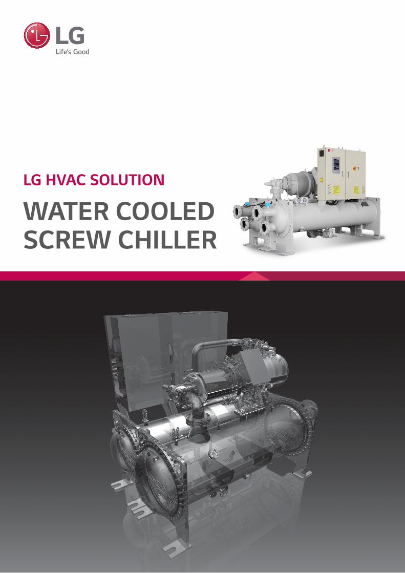
LG HVAC SOLUTION
WATER COOLED SCREW CHILLER
02 | 2015 LG Water Cooled Screw
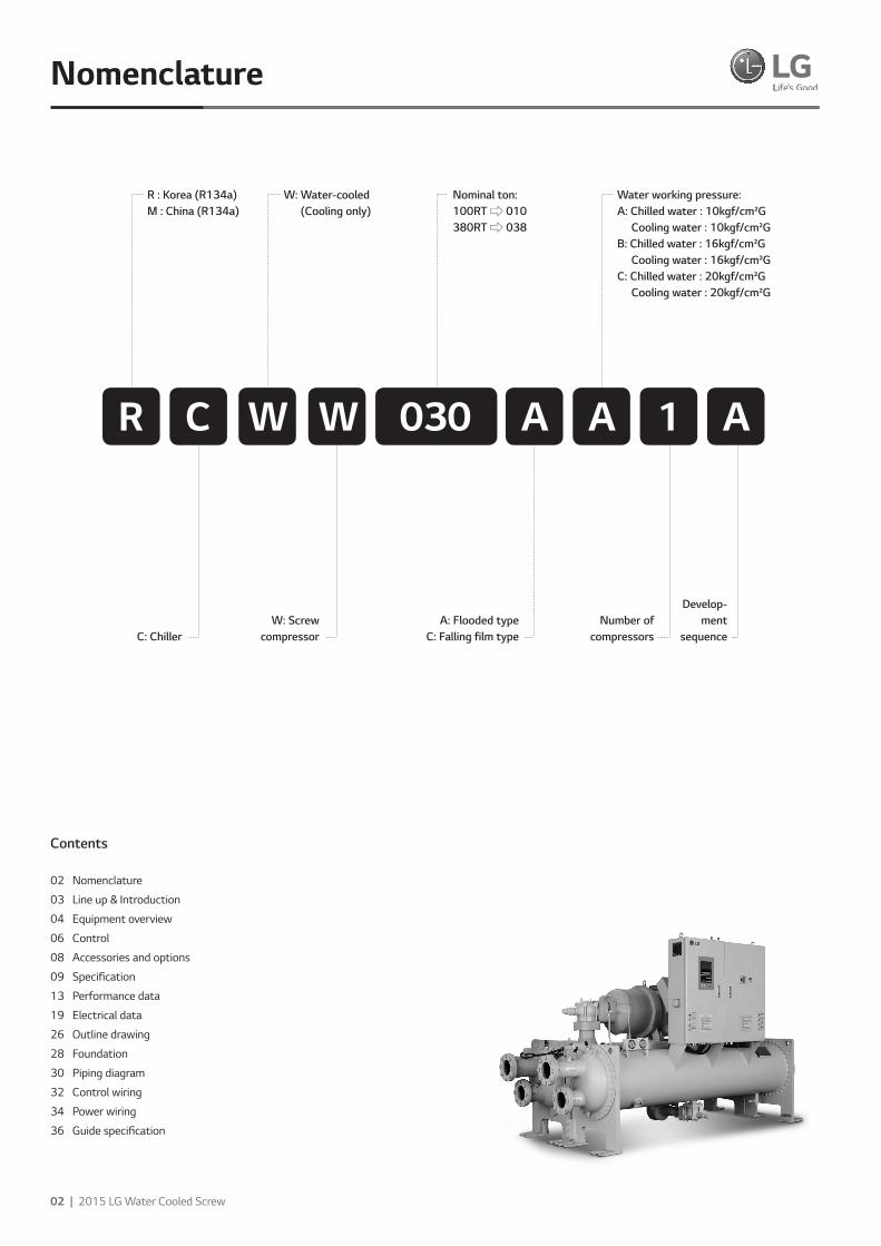
Nomenclature
R : Korea (R134a)M : China (R134a)
W: Water-cooled (Cooling only)
Water working pressure: A: Chilled water : 10kgf/cm²G Cooling water : 10kgf/cm²G B: Chilled water : 16kgf/cm²G Cooling water : 16kgf/cm²G C: Chilled water : 20kgf/cm²G Cooling water : 20kgf/cm²G
Nominal ton: 100RT ⇨ 010 380RT ⇨ 038
030R C W W A A 1 A
C: ChillerW: Screw
compressorNumber of
compressors
Develop-ment
sequenceA: Flooded type
C: Falling film type
Contents
02 Nomenclature
03 Line up & Introduction
04 Equipment overview
06 Control
08 Accessories and options
09 Specification
13 Performance data
19 Electrical data
26 Outline drawing
28 Foundation
30 Piping diagram
32 Control wiring
34 Power wiring
36 Guide specification
2015 LG HVAC Solution | 03
Line up Introduction
LG’s latest Water cooled screw chiller offers excellent operational efficiency
thanks to the company’s advanced technologies and unrivalled air conditioning
expertise. The new model’s advanced capacity control system valve help to
improve performance and efficiency. LG’s proprietary PID (Proportional, Integral,
Differential control), which controls hydraulic-head loss rate, helps to minimize
energy loss even further.
• High-performance compressor manufactured by specialized
manufacturer is adopted to ensure that the chiller is
economical and durable with low vibration and low noise.
• Highly integrated motherboard is adopted and hence the
function is strong and reliable.
• Advanced control algorithm is adopted to control chiller in
advance and hence avoid frequent stoppage protection of chiller.
• We have set complete safety protection function in order to
make chiller safely and reliably run.
• The linkage control and remote monitoring function of
peripheral equipment ensure that the chiller can run safely
and the operation and monitoring are convenient.
• The selection of excellent raw materials and fittings is the key
to guaranteeing chiller quality.
High efficiency, High reliability The RCWW & MCWW series is a kind of water-cooled spray screw chiller produced by LGE Corporation. Because of the special structure design, the chiller has high efficiency and high reliability.
Optimized dedicated motor R134a with high efficiency Made of premium grade, low-loss core steel with the special slot design, the motors of R134a dedicated compressors
can gain the highest efficiency with low power consumption. Besides, different winding for specific voltage and frequency requirement contributes to the best power factor and excellent performance.
Constructional design of dedicated screw compressor The screw compressor is characterized by a very compact design. Most of inner dimensions have been totally modified considering displacement volume, size of compression chamber, length & profile of rotors, oil separator specification and oil piping rearrangement, etc. to ensure consistency and cost effectiveness of the compressor.
Compressor • Semi-hermetical twin-rotor screw compressor.• Direct-drive, low speed/RPM for high efficiency and high reliability.• Only three moving parts, resulting in high reliability with
simple solution.• Field serviceable compressor and easy maintenance.• Precise rotor tip clearance.• The world’s advanced patent screw tooth with low noise,
smooth operation long life advantages.• A refrigerant dispersing cooling device is set internally for
compressor cooling, which uses return-refrigerant cooling.• Years of research and testing. The LG screw chiller has
amassed thousands of hours of testing, and conditions
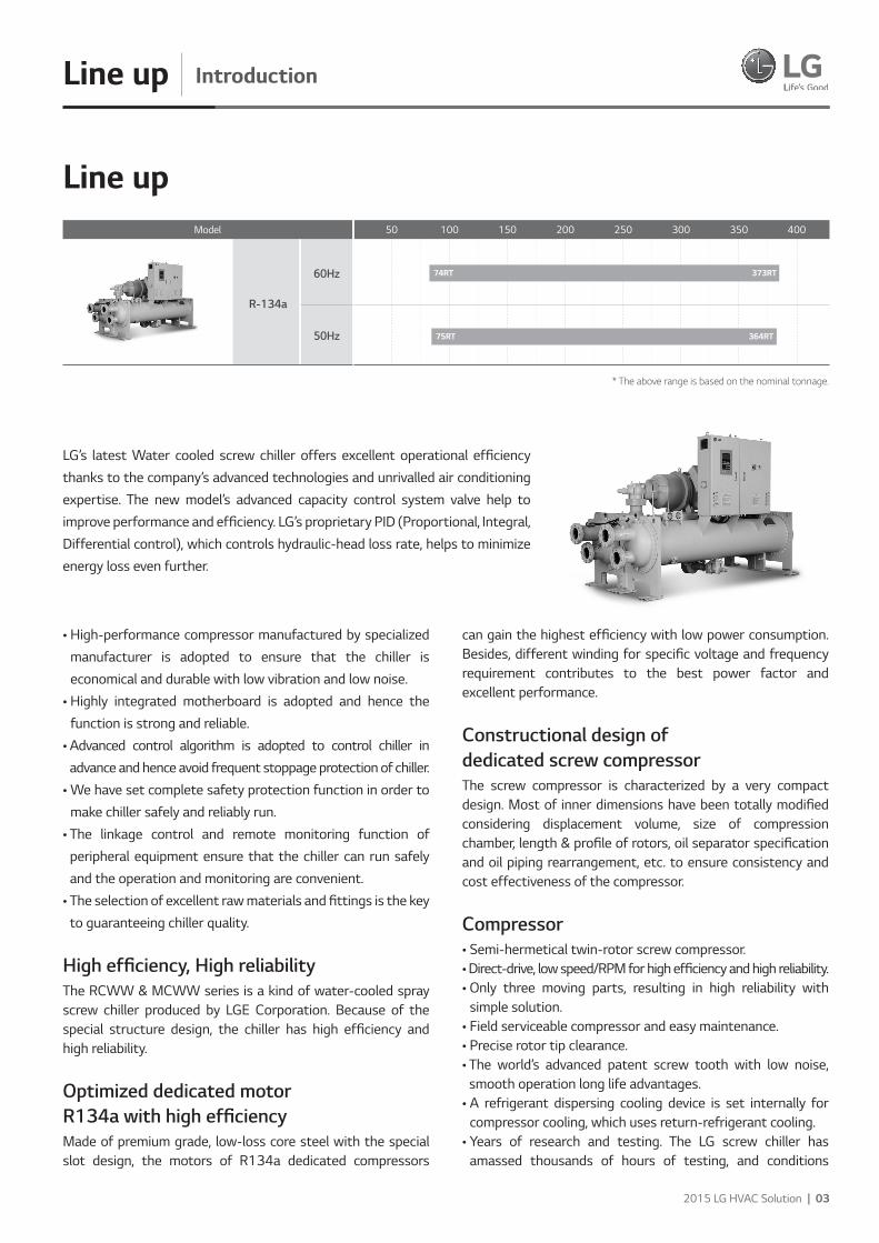
Line up50 100 150 200 250 300 350 400
74RT 373RT
75RT 364RT
* The above range is based on the nominal tonnage.
R-134a
60Hz
50Hz
Model
Features
04 | 2015 LG Water Cooled Screw
Equipment overview
beyond normal air conditioning applications.
Unit performance testingLG began promoting factory performance tests for air-cooled chillers and water-cooled chillers, to show we stand behind the products we design and build.The benefits of a performance test include verification of perfor-mance, prevention of operational problems, and assurance of a smooth start-up. Only a performance test conducted in a laboratory or laboratory grade facility will confirm both performance and operation of a specific chiller.Mostly factory performance tests go smoothly. If a problem occurs, LG personnel easily correct them and chiller is shipped to job site.When a factory performance test is requested, the test can be conducted at the specified, design conditions. The test facility has the capability to control ambient test conditions to assure our customers that our chillers will perform as predicted.
AHRI certification program and standards and codes Chillers conform to the following Standards and Codes:
• AHRI 550/590 - water chilling packages using the vapor compression cycle.
• ANSI/ASHRAE 34 - number designation and safety classification of refrigerants.
• ASME Section VIII (Option) - boiler and pressure vessel. • GB/T 18430.1 - water chilling (heat pump) packages using the
vapor compression cycle - part 1: water chilling (heat pump) packages for industrial & commercial and similar applications.(This code is only applied to product manufactured in China)
Equipment Overview Semi-hermetic twin compressorThe semi-hermetic screw compressor is developed especially for applications in air-conditioning and refrigeration. With high operating load design, each compressor is of high efficiency and reliability in all operating conditions. Each compressor has the latest and advanced 5-to-6 Patented Screw Rotor Profile designed to ensure high capacity and efficiency in all operating conditions.
The compressor is equipped with separated radial and axial bearings, liquid injection and economizer connection, PTC motor temperature thermistors and discharge temperature thermistors, a motor protector, and oil level switch and
oil pressure differential switch and other accessories. The complete accessories and their new designs guarantee the compressor has the best reliability, longest bearing life during heavy duty running and strict operating conditions.
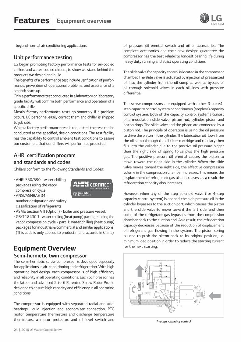
The slide valve for capacity control is located in the compressor chamber. The slide valve is actuated by injection of pressurized oil into the cylinder from the oil sump as well as bypass of oil through solenoid valves in each oil lines with pressure differential.
The screw compressors are equipped with either 3-step/4-step capacity control system or continuous (stepless) capacity control system. Both of the capacity control systems consist of a modulation slide valve, piston rod, cylinder, piston and piston rings. The slide valve and the piston are connected by a piston rod. The principle of operation is using the oil pressure to drive the piston in the cylinder. The lubrication oil flows from the oil sump through the oil filter cartridge and capillary then fills into the cylinder due to the positive oil pressure bigger than the right side of spring force plus the high pressure gas. The positive pressure differential causes the piston to move toward the right side in the cylinder. When the slide valve moves toward the right side, the effective compression volume in the compression chamber increases. This means the displacement of refrigerant gas also increases, as a result the refrigeration capacity also increases.
However, when any of the step solenoid valve (for 4-step capacity control system) is opened, the high pressure oil in the cylinder bypasses to the suction port, which causes the piston and the slide valve to move toward the left side, and then some of the refrigerant gas bypasses from the compression chamber back to the suction end. As a result, the refrigeration capacity decreases because of the reduction of displacement of refrigerant gas flowing in the system. The piston spring is used to push the piston back to its original position, i.e. minimum load position in order to reduce the starting current for the next starting.
4-steps capacity control
Features
2015 LG HVAC Solution | 05
Heat exchangerEvaporatorFalling film type“Falling film” shell and tube type evaporator having refrigerant in the shell and chilled water inside the tubes. Advantage of this type evaporator is higher heat transfer performance and reduced refrigerant charge.Distributer located on the top side of inside shell makes uniform flow of refrigerant, this refrigerant flows downward by gravity as a continuous film.The shell is of welded carbon steel construction with steel
tube sheets and copper heat exchange tubes. Removable steel water boxes at both ends of the cooler allow tube cleaning without disturbing the refrigerant circuit. Tubes are mechanically expanded into tube sheets with double grooves to ensure leak tight and trouble free operation. Multiple compressor/ circuit chillers have coolers with separate refrigeration circuits for each compressor.
Each refrigeration circuit is provided with its own pressure relief valve. All chillers are fitted with drain valves on the removable heads and shell. All coolers are factory insulated with 19mm of closed cell expanded synthetic rubber with all joints vapor sealed.
Expansion device Expansion unit consists of butterfly valve and orifice. At 100% load situation, the pressure loss at the orifice is smaller than the refrigerant pressure loss in the condenser, thus the super-cooled refrigerant passes through the orifice.
At this stage the maximum amount of refrigerant is flowing into the evaporator. As the load reduces gradually, the circulating amount of refrigerant also reduces and accordingly the refrigerant level in the condenser is getting low.
When the amount of liquid refrigerant reduces, the gas amount in the orifice is getting larger, raising the resistance thus controlling the flow rate.
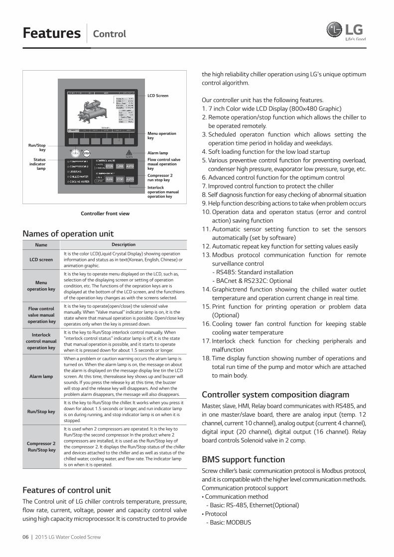
Control Control Panel Layout Function HMI with 7 inch Color LCD is composed as a graphic type. There are start/stop, control valve 2 and Compressor 2, compressor, lead/lag lamp, and chilled water / coolant flow lamp keys. There are ‘function keys’ at the bottom of the screen that change according to the current screen to be able to access lower categories.
The Display of screw chiller's control unit consists of; basic screen where present operation can be checked, and main menu which user can use conveniently for user setting, problem/warning information check, and system menu which is for sensor setting and system pertain item setting.
Equipment overview
No Component No Component
1 Suction filter 10 Lubricant
2 Gas in (low pressure) 11 Oil separator catridge
3 Motor 12Gas out (high pressure without oil)
4 Oil filter catridge 13 Capillary
5 Suction bearings 14 Solenold valve, SV2
6 Male rotor 15 Solenold valve, SV1
7 Discharge bearings 16 Orifice
8 Oil separator baffle 17 Slide valve
9 Gas out (high pressure with oil)
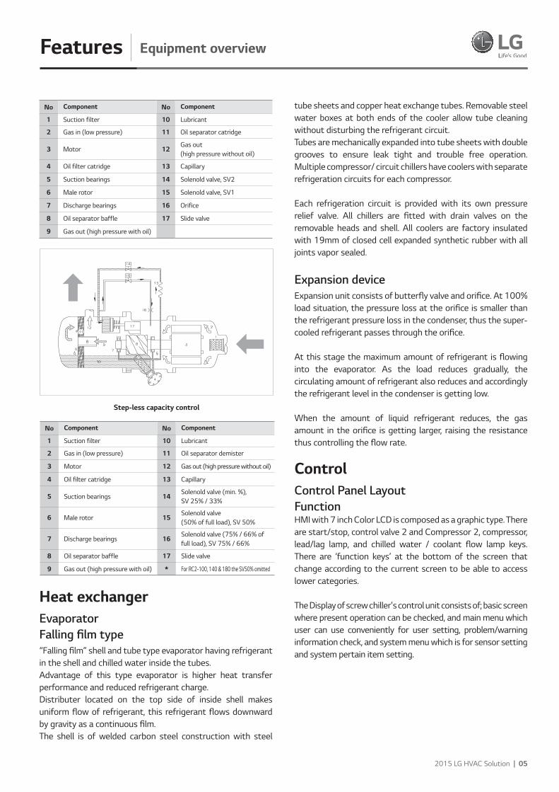
Step-less capacity control
No Component No Component
1 Suction filter 10 Lubricant
2 Gas in (low pressure) 11 Oil separator demister
3 Motor 12 Gas out (high pressure without oil)
4 Oil filter catridge 13 Capillary
5 Suction bearings 14Solenold valve (min. %), SV 25% / 33%
6 Male rotor 15Solenold valve (50% of full load), SV 50%
7 Discharge bearings 16Solenold valve (75% / 66% of full load), SV 75% / 66%
8 Oil separator baffle 17 Slide valve
9 Gas out (high pressure with oil) * For RC2-100, 140 & 180 the SV50% omitted
Features
06 | 2015 LG Water Cooled Screw
Control
Names of operation unitName Description
LCD screenIt is the color LCD(Liquid Crystal Display) showing operation information and status as in text(Korean, English, Chinese) or animation graphic.
Menu operation key
It is the key to operate menu displayed on the LCD, such as, selection of the displaying screen or setting of operation condition, etc. The functions of the oepration keys are is displayed at the bottom of the LCD screen, and the functhions of the operation key changes as with the screens selected.
Flow control valve manual
operation key
It is the key to operate(open/close) the solenoid valve manually. When "Valve manual" indicator lamp is on, it is the state where that manual operation is possible. Open/close key operates only when the key is pressed down.
Interlock control manual operation key
It is the key to Run/Stop interlock control manually. When "interlock control status" indicator lamp is off, it is the state that manual operation is possible, and it starts to operate when it is pressed down for about 1.5 seconds or longer.
Alarm lamp
When a problem or caution warning occurs the alram lamp is turned on. When the alarm lamp is on, the message on about the alarm is displayed on the message display line tin the LCD screen. At this time, therealease key shows up and buzzer will sounds. If you press the release ky at this time, the buzzer will stop and the release key will disappears. And when the problem alarm disappears, the message will also disappears.
Run/Stop key
It is the key to Run/Stop the chiller. It works when you press it down for about 1.5 seconds or longer, and run indicator lamp is on during running, and stop indicator lamp is on when it is stopped.
Compressor 2 Run/Stop key
It is used when 2 compressors are operated. It is the key to Run/Stop the second compressor. In the product where 2 compressors are installed, it is used as the Run/Stop key of the compressor 2. It displays the Run/Stop status of the chiller and devices attached to the chiller and as well as status of the chilled water, cooling water, and flow rate. The indicator lamp is on when it is operated.
Features of control unitThe Control unit of LG chiller controls temperature, pressure, flow rate, current, voltage, power and capacity control valve using high capacity microprocessor. It is constructed to provide
the high reliability chiller operation using LG's unique optimum control algorithm.
Our controller unit has the following features.1. 7 inch Color wide LCD Display (800x480 Graphic)2. Remote operation/stop function which allows the chiller to
be operated remotely.3. Scheduled operaton function which allows setting the
operation time period in holiday and weekdays.4. Soft loading function for the low load startup5. Various preventive control function for preventing overload,
condenser high pressure, evaporator low pressure, surge, etc.6. Advanced control function for the optimum control7. Improved control function to protect the chiller8. Self diagnosis function for easy checking of abnormal situation9. Help function describing actions to take when problem occurs10. Operation data and operaton status (error and control
action) saving function11. Automatic sensor setting function to set the sensors
automatically (set by software)12. Automatic repeat key function for setting values easily13. Modbus protocol communication function for remote
surveillance control - RS485: Standard installation - BACnet & RS232C: Optional14. Graphictrend function showing the chilled water outlet
temperature and operation current change in real time.15. Print function for printing operation or problem data
(Optional)16. Cooling tower fan control function for keeping stable
cooling water temperature17. Interlock check function for checking peripherals and
malfunction18. Time display function showing number of operations and
total run time of the pump and motor which are attached to main body.
Controller system composition diagramMaster, slave, HMI, Relay board communicates with RS485, and in one master/slave board, there are analog input (temp. 12 channel, current 10 channel), analog output (current 4 channel), digital input (20 channel), digital output (16 channel). Relay board controls Solenoid valve in 2 comp.
BMS support functionScrew chiller’s basic communication protocol is Modbus protocol, and it is compatible with the higher level communication methods.Communication protocol support• Communication method - Basic: RS-485, Ethernet(Optional)• Protocol - Basic: MODBUS
Controller front view
LCD Screen
Run/Stopkey
Status indicator
lamp
Menu operation key
Flow control valve maual operation key
Compressor 2 run stop key
Interlock operation manual operation key
Alarm lamp
Features
2015 LG HVAC Solution | 07
Control
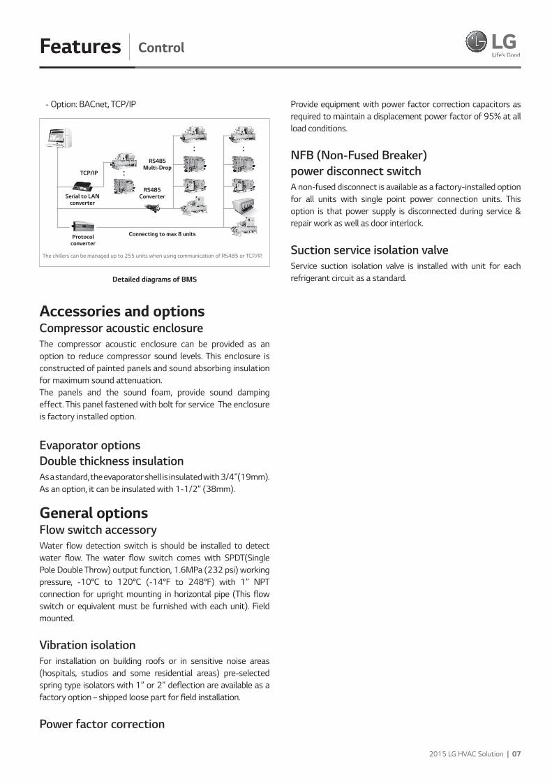
- Option: BACnet, TCP/IP
Accessories and optionsCompressor acoustic enclosure The compressor acoustic enclosure can be provided as an option to reduce compressor sound levels. This enclosure is constructed of painted panels and sound absorbing insulation for maximum sound attenuation. The panels and the sound foam, provide sound damping effect. This panel fastened with bolt for service The enclosure is factory installed option.
Evaporator options Double thickness insulation As a standard, the evaporator shell is insulated with 3/4”(19mm). As an option, it can be insulated with 1-1/2” (38mm).
General options Flow switch accessory Water flow detection switch is should be installed to detect water flow. The water flow switch comes with SPDT(Single Pole Double Throw) output function, 1.6MPa (232 psi) working pressure, -10°C to 120°C (-14°F to 248°F) with 1” NPT connection for upright mounting in horizontal pipe (This flow switch or equivalent must be furnished with each unit). Field mounted.
Vibration isolation For installation on building roofs or in sensitive noise areas (hospitals, studios and some residential areas) pre-selected spring type isolators with 1” or 2” deflection are available as a factory option – shipped loose part for field installation.
Power factor correction
Provide equipment with power factor correction capacitors as required to maintain a displacement power factor of 95% at all load conditions.
NFB (Non-Fused Breaker) power disconnect switchA non-fused disconnect is available as a factory-installed option for all units with single point power connection units. This option is that power supply is disconnected during service & repair work as well as door interlock.
Suction service isolation valve Service suction isolation valve is installed with unit for each refrigerant circuit as a standard.
Protocolconverter
TCP/IP
Serial to LANconverter
RS485 Converter
RS485Multi-Drop
Connecting to max 8 units
The chillers can be managed up to 255 units when using communication of RS485 or TCP/IP.
Detailed diagrams of BMS
08 | 2015 LG Water Cooled Screw
Accessories and optionsFeatures
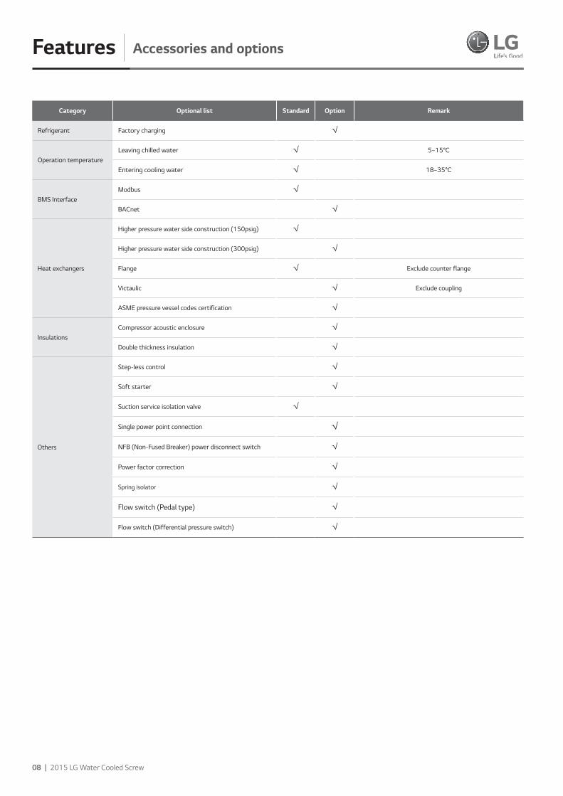
Category Optional list Standard Option Remark
Refrigerant Factory charging √
Operation temperatureLeaving chilled water √ 5~15°C
Entering cooling water √ 18~35°C
BMS Interface Modbus √
BACnet √
Heat exchangers
Higher pressure water side construction (150psig) √
Higher pressure water side construction (300psig) √
Flange √ Exclude counter flange
Victaulic √ Exclude coupling
ASME pressure vessel codes certification √
Insulations Compressor acoustic enclosure √
Double thickness insulation √
Others
Step-less control √
Soft starter √
Suction service isolation valve √
Single power point connection √
NFB (Non-Fused Breaker) power disconnect switch √
Power factor correction √
Spring isolator √
Flow switch (Pedal type) √
Flow switch (Differential pressure switch) √
2015 LG HVAC Solution | 09
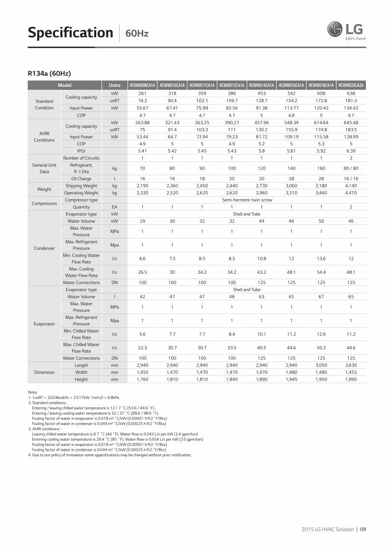
Specification 60Hz
Model Units RCWW008CA1A RCWW010CA1A RCWW011CA1A RCWW012CA1A RCWW014CA1A RCWW016CA1A RCWW018CA1A RCWW020CA2A
Standard Condition
Cooling capacitykW 261 318 359 386 453 542 608 638
usRT 74.2 90.4 102.1 109.7 128.7 154.2 172.8 181.3
Input Power kW 55.67 67.41 75.99 82.56 91.38 113.77 120.42 134.42
COP 4.7 4.7 4.7 4.7 5 4.8 5 4.7
AHRI Conditions
Cooling capacitykW 263.88 321.43 363.25 390.27 457.96 548.39 614.64 645.48
usRT 75 91.4 103.3 111 130.2 155.9 174.8 183.5Input Power kW 53.44 64.7 72.94 79.23 87.72 109.19 115.58 128.99
COP 4.9 5 5 4.9 5.2 5 5.3 5IPLV 5.41 5.42 5.45 5.43 5.8 5.61 5.92 6.39
General Unit Data
Number of Circuits 1 1 1 1 1 1 1 2Refrigerant,
R-134akg 70 80 90 100 120 140 160 80 / 80
Oil Charge l 16 16 18 20 20 28 28 16 / 16
WeightShipping Weight kg 2,190 2,360 2,450 2,440 2,730 3,060 3,180 4,140
Operating Weight kg 2,330 2,520 2,620 2,620 2,960 3,310 3,460 4,410
CompressorsCompressor type Semi-hermetic twin screw
Quantity EA 1 1 1 1 1 1 1 2
Condenser
Evaporator type kW Shell and TubeWater Volume kW 29 30 32 32 44 46 50 46
Max. Water Pressure
MPa 1 1 1 1 1 1 1 1
Max. Refrigerant Pressure
Mpa 1 1 1 1 1 1 1 1
Min. Cooling Water Flow Rate
l/s 6.6 7.5 8.5 8.5 10.8 12 13.6 12
Max. Cooling Water Flow Rate
l/s 26.5 30 34.2 34.2 43.2 48.1 54.4 48.1
Water Connections DN 100 100 100 100 125 125 125 125
Evaporator
Evaporator type Shell and TubeWater Volume l 42 47 47 48 63 65 67 65
Max. Water Pressure
MPa 1 1 1 1 1 1 1 1
Max. Refrigerant Pressure
Mpa 1 1 1 1 1 1 1 1
Min. Chilled Water Flow Rate
l/s 5.6 7.7 7.7 8.4 10.1 11.2 12.6 11.2
Max. Chilled Water Flow Rate
l/s 22.3 30.7 30.7 33.5 40.5 44.6 50.2 44.6
Water Connections DN 100 100 100 100 125 125 125 125
DimensionLength mm 2,940 2,940 2,940 2,940 2,940 2,940 3,050 3,630Width mm 1,450 1,470 1,470 1,470 1,470 1,480 1,480 1,455Height mm 1,760 1,810 1,810 1,840 1,890 1,945 1,950 1,890
R134a (60Hz)
Note: 1. 1usRT = 3,024kcal/hr = 3.517kW, 1mH2O = 9.8kPa2. Standard conditions : Entering / leaving chilled water temperature is 12 / 7 ˚C (53.6 / 44.6 ˚F). Entering / leaving cooling water temperature is 32 / 37 ˚C (89.6 / 98.6 ˚F). Fouling factor of water in evaporator is 0.018 m²·˚C/kW (0.00001 h·ft2·˚F/Btu) Fouling factor of water in condenser is 0.044 m²·˚C/kW (0.00025 h·ft2·˚F/Btu)3. AHRI conditions : Leaving chilled water temperature is 6.7 ˚C (44 ˚F). Water flow is 0.043 L/s per kW (2.4 gpm/ton) Entering cooling water temperature is 29.4 ˚C (85 ˚F). Water flow is 0.054 L/s per kW (3.0 gpm/ton) Fouling factor of water in evaporator is 0.018 m²·˚C/kW (0.00001 h·ft2·˚F/Btu) Fouling factor of water in condenser is 0.044 m²·˚C/kW (0.00025 h·ft2·˚F/Btu)4. Due to our policy of innovation some sppecifications may be changed without prior notification.
010 | 2015 LG Water Cooled Screw
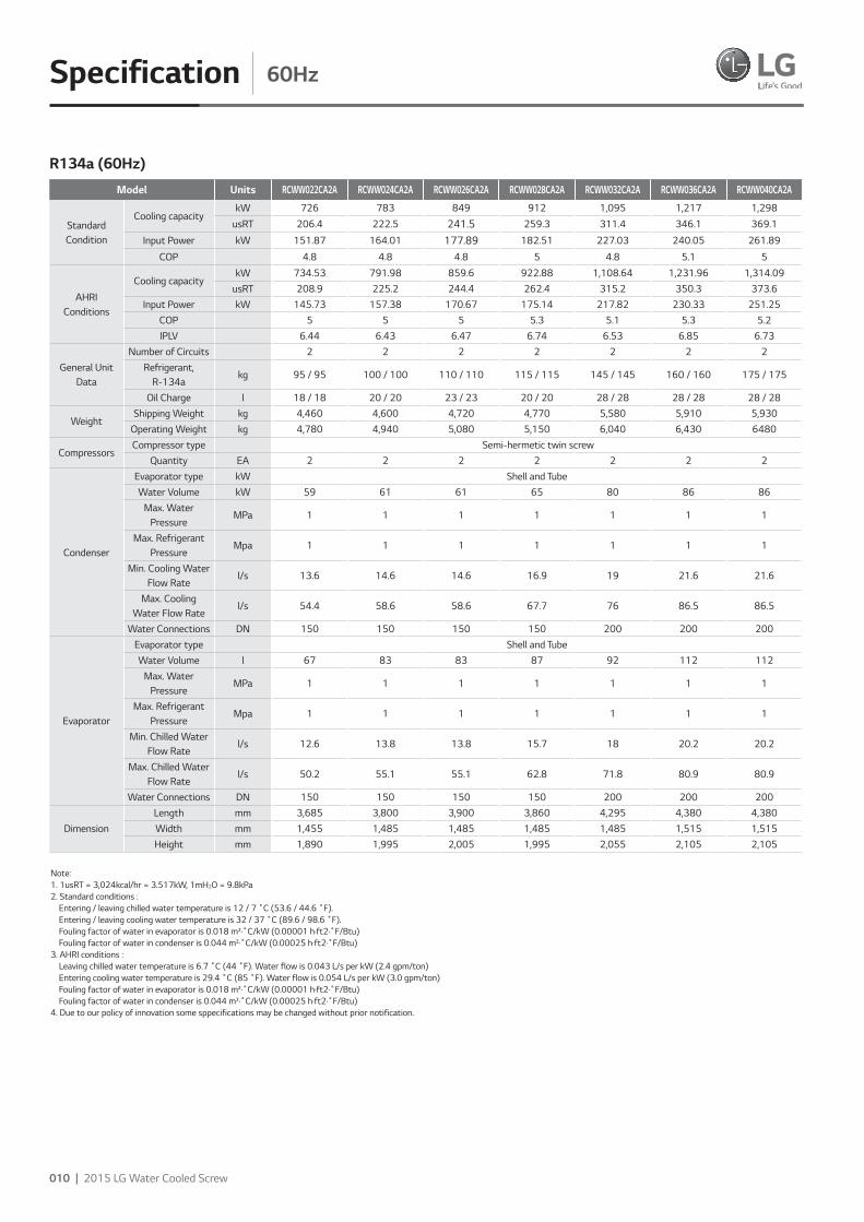
Specification 60Hz
Model Units RCWW022CA2A RCWW024CA2A RCWW026CA2A RCWW028CA2A RCWW032CA2A RCWW036CA2A RCWW040CA2A
Standard Condition
Cooling capacitykW 726 783 849 912 1,095 1,217 1,298
usRT 206.4 222.5 241.5 259.3 311.4 346.1 369.1
Input Power kW 151.87 164.01 177.89 182.51 227.03 240.05 261.89
COP 4.8 4.8 4.8 5 4.8 5.1 5
AHRI Conditions
Cooling capacitykW 734.53 791.98 859.6 922.88 1,108.64 1,231.96 1,314.09
usRT 208.9 225.2 244.4 262.4 315.2 350.3 373.6Input Power kW 145.73 157.38 170.67 175.14 217.82 230.33 251.25
COP 5 5 5 5.3 5.1 5.3 5.2IPLV 6.44 6.43 6.47 6.74 6.53 6.85 6.73
General Unit Data
Number of Circuits 2 2 2 2 2 2 2Refrigerant,
R-134akg 95 / 95 100 / 100 110 / 110 115 / 115 145 / 145 160 / 160 175 / 175
Oil Charge l 18 / 18 20 / 20 23 / 23 20 / 20 28 / 28 28 / 28 28 / 28
WeightShipping Weight kg 4,460 4,600 4,720 4,770 5,580 5,910 5,930
Operating Weight kg 4,780 4,940 5,080 5,150 6,040 6,430 6480
CompressorsCompressor type Semi-hermetic twin screw
Quantity EA 2 2 2 2 2 2 2
Condenser
Evaporator type kW Shell and TubeWater Volume kW 59 61 61 65 80 86 86
Max. Water Pressure
MPa 1 1 1 1 1 1 1
Max. Refrigerant Pressure
Mpa 1 1 1 1 1 1 1
Min. Cooling Water Flow Rate
l/s 13.6 14.6 14.6 16.9 19 21.6 21.6
Max. Cooling Water Flow Rate
l/s 54.4 58.6 58.6 67.7 76 86.5 86.5
Water Connections DN 150 150 150 150 200 200 200
Evaporator
Evaporator type Shell and TubeWater Volume l 67 83 83 87 92 112 112
Max. Water Pressure
MPa 1 1 1 1 1 1 1
Max. Refrigerant Pressure
Mpa 1 1 1 1 1 1 1
Min. Chilled Water Flow Rate
l/s 12.6 13.8 13.8 15.7 18 20.2 20.2
Max. Chilled Water Flow Rate
l/s 50.2 55.1 55.1 62.8 71.8 80.9 80.9
Water Connections DN 150 150 150 150 200 200 200
DimensionLength mm 3,685 3,800 3,900 3,860 4,295 4,380 4,380Width mm 1,455 1,485 1,485 1,485 1,485 1,515 1,515Height mm 1,890 1,995 2,005 1,995 2,055 2,105 2,105
R134a (60Hz)
Note: 1. 1usRT = 3,024kcal/hr = 3.517kW, 1mH2O = 9.8kPa2. Standard conditions : Entering / leaving chilled water temperature is 12 / 7 ˚C (53.6 / 44.6 ˚F). Entering / leaving cooling water temperature is 32 / 37 ˚C (89.6 / 98.6 ˚F). Fouling factor of water in evaporator is 0.018 m²·˚C/kW (0.00001 h·ft2·˚F/Btu) Fouling factor of water in condenser is 0.044 m²·˚C/kW (0.00025 h·ft2·˚F/Btu)3. AHRI conditions : Leaving chilled water temperature is 6.7 ˚C (44 ˚F). Water flow is 0.043 L/s per kW (2.4 gpm/ton) Entering cooling water temperature is 29.4 ˚C (85 ˚F). Water flow is 0.054 L/s per kW (3.0 gpm/ton) Fouling factor of water in evaporator is 0.018 m²·˚C/kW (0.00001 h·ft2·˚F/Btu) Fouling factor of water in condenser is 0.044 m²·˚C/kW (0.00025 h·ft2·˚F/Btu)4. Due to our policy of innovation some sppecifications may be changed without prior notification.
2015 LG HVAC Solution | 011
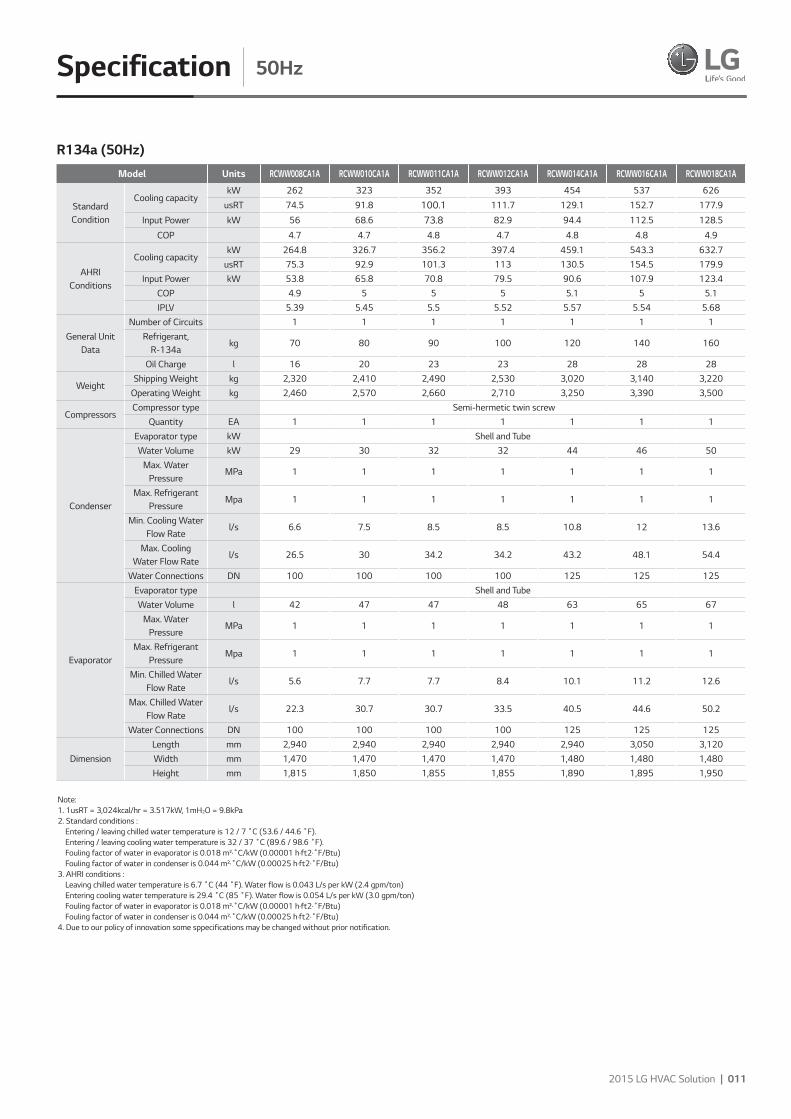
Specification 50Hz
Model Units RCWW008CA1A RCWW010CA1A RCWW011CA1A RCWW012CA1A RCWW014CA1A RCWW016CA1A RCWW018CA1A
Standard Condition
Cooling capacitykW 262 323 352 393 454 537 626
usRT 74.5 91.8 100.1 111.7 129.1 152.7 177.9
Input Power kW 56 68.6 73.8 82.9 94.4 112.5 128.5
COP 4.7 4.7 4.8 4.7 4.8 4.8 4.9
AHRI Conditions
Cooling capacitykW 264.8 326.7 356.2 397.4 459.1 543.3 632.7
usRT 75.3 92.9 101.3 113 130.5 154.5 179.9Input Power kW 53.8 65.8 70.8 79.5 90.6 107.9 123.4
COP 4.9 5 5 5 5.1 5 5.1IPLV 5.39 5.45 5.5 5.52 5.57 5.54 5.68
General Unit Data
Number of Circuits 1 1 1 1 1 1 1Refrigerant,
R-134akg 70 80 90 100 120 140 160
Oil Charge l 16 20 23 23 28 28 28
WeightShipping Weight kg 2,320 2,410 2,490 2,530 3,020 3,140 3,220
Operating Weight kg 2,460 2,570 2,660 2,710 3,250 3,390 3,500
CompressorsCompressor type Semi-hermetic twin screw
Quantity EA 1 1 1 1 1 1 1
Condenser
Evaporator type kW Shell and TubeWater Volume kW 29 30 32 32 44 46 50
Max. Water Pressure
MPa 1 1 1 1 1 1 1
Max. Refrigerant Pressure
Mpa 1 1 1 1 1 1 1
Min. Cooling Water Flow Rate
l/s 6.6 7.5 8.5 8.5 10.8 12 13.6
Max. Cooling Water Flow Rate
l/s 26.5 30 34.2 34.2 43.2 48.1 54.4
Water Connections DN 100 100 100 100 125 125 125
Evaporator
Evaporator type Shell and TubeWater Volume l 42 47 47 48 63 65 67
Max. Water Pressure
MPa 1 1 1 1 1 1 1
Max. Refrigerant Pressure
Mpa 1 1 1 1 1 1 1
Min. Chilled Water Flow Rate
l/s 5.6 7.7 7.7 8.4 10.1 11.2 12.6
Max. Chilled Water Flow Rate
l/s 22.3 30.7 30.7 33.5 40.5 44.6 50.2
Water Connections DN 100 100 100 100 125 125 125
DimensionLength mm 2,940 2,940 2,940 2,940 2,940 3,050 3,120Width mm 1,470 1,470 1,470 1,470 1,480 1,480 1,480Height mm 1,815 1,850 1,855 1,855 1,890 1,895 1,950
R134a (50Hz)
Note: 1. 1usRT = 3,024kcal/hr = 3.517kW, 1mH2O = 9.8kPa2. Standard conditions : Entering / leaving chilled water temperature is 12 / 7 ˚C (53.6 / 44.6 ˚F). Entering / leaving cooling water temperature is 32 / 37 ˚C (89.6 / 98.6 ˚F). Fouling factor of water in evaporator is 0.018 m²·˚C/kW (0.00001 h·ft2·˚F/Btu) Fouling factor of water in condenser is 0.044 m²·˚C/kW (0.00025 h·ft2·˚F/Btu)3. AHRI conditions : Leaving chilled water temperature is 6.7 ˚C (44 ˚F). Water flow is 0.043 L/s per kW (2.4 gpm/ton) Entering cooling water temperature is 29.4 ˚C (85 ˚F). Water flow is 0.054 L/s per kW (3.0 gpm/ton) Fouling factor of water in evaporator is 0.018 m²·˚C/kW (0.00001 h·ft2·˚F/Btu) Fouling factor of water in condenser is 0.044 m²·˚C/kW (0.00025 h·ft2·˚F/Btu)4. Due to our policy of innovation some sppecifications may be changed without prior notification.

012 | 2015 LG Water Cooled Screw
Specification 50Hz
Model Units RCWW020CA2A RCWW022CA2A RCWW024CA2A RCWW028CA2A RCWW032CA2A RCWW036CA2A
Standard Condition
Cooling capacitykW 649 713 798 915 1,087 1,266
usRT 184.5 202.6 226.9 260.3 309 360
Input Power kW 136.44 147.07 164.17 188.09 223.83 255.59
COP 4.8 4.8 4.9 4.9 4.9 5
AHRI Conditions
Cooling capacitykW 656.92 721.28 807.83 926.52 1,099.94 1,281.75
usRT 186.8 205.1 229.7 263.4 312.7 364.4Input Power kW 130.92 141.13 157.52 180.48 214.75 245.22
COP 5 5.1 5.1 5.1 5.1 5.2IPLV 6.42 6.52 6.55 6.56 6.57 6.72
General Unit Data
Number of Circuits 2 2 2 2 2 2Refrigerant,
R-134akg 85 / 85 90 / 90 105 / 105 120 / 120 140 / 140 165 / 165
Oil Charge l 20 / 20 23 / 23 23 / 23 28 / 28 28 / 28 28 / 28
WeightShipping Weight kg 4,220 4,520 4,780 5,360 5,710 5,990
Operating Weight kg 4,500 4,830 5,130 5,750 6,160 6,520
CompressorsCompressor type Semi-hermetic twin screw
Quantity EA 2 2 2 2 2 2
Condenser
Evaporator type kW Shell and TubeWater Volume kW 46 59 61 65 80 86
Max. Water Pressure
MPa 1 1 1 1 1 1
Max. Refrigerant Pressure
Mpa 1 1 1 1 1 1
Min. Cooling Water Flow Rate
l/s 12 13.6 14.6 16.9 19 21.6
Max. Cooling Water Flow Rate
l/s 48.1 54.4 58.6 67.7 76 86.5
Water Connections DN 125 150 150 150 200 200
Evaporator
Evaporator type Shell and TubeWater Volume l 65 67 83 87 92 112
Max. Water Pressure
MPa 1 1 1 1 1 1
Max. Refrigerant Pressure
Mpa 1 1 1 1 1 1
Min. Chilled Water Flow Rate
l/s 11.2 12.6 13.8 15.7 18 20.2
Max. Chilled Water Flow Rate
l/s 44.6 50.2 55.1 62.8 71.8 80.9
Water Connections DN 125 150 150 150 200 200
DimensionLength mm 3,800 3,900 4,268 4,295 4,380 4,520Width mm 1,455 1,455 1,485 1,485 1,515 1,545Height mm 1,960 1,970 2,005 2,050 2,060 2,075
R134a (50Hz)
Note: 1. 1usRT = 3,024kcal/hr = 3.517kW, 1mH2O = 9.8kPa2. Standard conditions : Entering / leaving chilled water temperature is 12 / 7 ˚C (53.6 / 44.6 ˚F). Entering / leaving cooling water temperature is 32 / 37 ˚C (89.6 / 98.6 ˚F). Fouling factor of water in evaporator is 0.018 m²·˚C/kW (0.00001 h·ft2·˚F/Btu) Fouling factor of water in condenser is 0.044 m²·˚C/kW (0.00025 h·ft2·˚F/Btu)3. AHRI conditions : Leaving chilled water temperature is 6.7 ˚C (44 ˚F). Water flow is 0.043 L/s per kW (2.4 gpm/ton) Entering cooling water temperature is 29.4 ˚C (85 ˚F). Water flow is 0.054 L/s per kW (3.0 gpm/ton) Fouling factor of water in evaporator is 0.018 m²·˚C/kW (0.00001 h·ft2·˚F/Btu) Fouling factor of water in condenser is 0.044 m²·˚C/kW (0.00025 h·ft2·˚F/Btu)4. Due to our policy of innovation some sppecifications may be changed without prior notification.
2015 LG HVAC Solution | 013
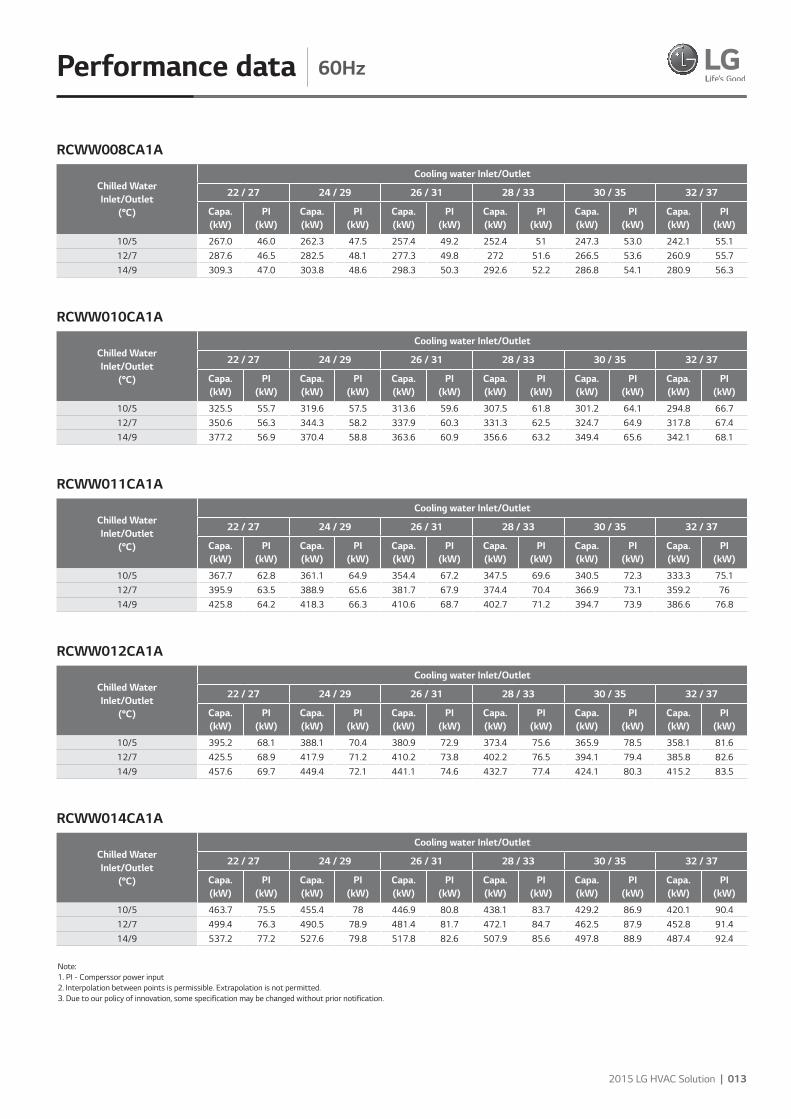
Performance data 60Hz
Chilled WaterInlet/Outlet
(°C)
Cooling water Inlet/Outlet
22 / 27 24 / 29 26 / 31 28 / 33 30 / 35 32 / 37
Capa.(kW)
PI(kW)
Capa.(kW)
PI(kW)
Capa.(kW)
PI(kW)
Capa.(kW)
PI(kW)
Capa.(kW)
PI(kW)
Capa.(kW)
PI(kW)
10/5 267.0 46.0 262.3 47.5 257.4 49.2 252.4 51 247.3 53.0 242.1 55.112/7 287.6 46.5 282.5 48.1 277.3 49.8 272 51.6 266.5 53.6 260.9 55.714/9 309.3 47.0 303.8 48.6 298.3 50.3 292.6 52.2 286.8 54.1 280.9 56.3
Chilled WaterInlet/Outlet
(°C)
Cooling water Inlet/Outlet
22 / 27 24 / 29 26 / 31 28 / 33 30 / 35 32 / 37
Capa.(kW)
PI(kW)
Capa.(kW)
PI(kW)
Capa.(kW)
PI(kW)
Capa.(kW)
PI(kW)
Capa.(kW)
PI(kW)
Capa.(kW)
PI(kW)
10/5 325.5 55.7 319.6 57.5 313.6 59.6 307.5 61.8 301.2 64.1 294.8 66.712/7 350.6 56.3 344.3 58.2 337.9 60.3 331.3 62.5 324.7 64.9 317.8 67.414/9 377.2 56.9 370.4 58.8 363.6 60.9 356.6 63.2 349.4 65.6 342.1 68.1
Chilled WaterInlet/Outlet
(°C)
Cooling water Inlet/Outlet
22 / 27 24 / 29 26 / 31 28 / 33 30 / 35 32 / 37
Capa.(kW)
PI(kW)
Capa.(kW)
PI(kW)
Capa.(kW)
PI(kW)
Capa.(kW)
PI(kW)
Capa.(kW)
PI(kW)
Capa.(kW)
PI(kW)
10/5 367.7 62.8 361.1 64.9 354.4 67.2 347.5 69.6 340.5 72.3 333.3 75.112/7 395.9 63.5 388.9 65.6 381.7 67.9 374.4 70.4 366.9 73.1 359.2 7614/9 425.8 64.2 418.3 66.3 410.6 68.7 402.7 71.2 394.7 73.9 386.6 76.8
Chilled WaterInlet/Outlet
(°C)
Cooling water Inlet/Outlet
22 / 27 24 / 29 26 / 31 28 / 33 30 / 35 32 / 37
Capa.(kW)
PI(kW)
Capa.(kW)
PI(kW)
Capa.(kW)
PI(kW)
Capa.(kW)
PI(kW)
Capa.(kW)
PI(kW)
Capa.(kW)
PI(kW)
10/5 395.2 68.1 388.1 70.4 380.9 72.9 373.4 75.6 365.9 78.5 358.1 81.612/7 425.5 68.9 417.9 71.2 410.2 73.8 402.2 76.5 394.1 79.4 385.8 82.614/9 457.6 69.7 449.4 72.1 441.1 74.6 432.7 77.4 424.1 80.3 415.2 83.5
Chilled WaterInlet/Outlet
(°C)
Cooling water Inlet/Outlet
22 / 27 24 / 29 26 / 31 28 / 33 30 / 35 32 / 37
Capa.(kW)
PI(kW)
Capa.(kW)
PI(kW)
Capa.(kW)
PI(kW)
Capa.(kW)
PI(kW)
Capa.(kW)
PI(kW)
Capa.(kW)
PI(kW)
10/5 463.7 75.5 455.4 78 446.9 80.8 438.1 83.7 429.2 86.9 420.1 90.412/7 499.4 76.3 490.5 78.9 481.4 81.7 472.1 84.7 462.5 87.9 452.8 91.414/9 537.2 77.2 527.6 79.8 517.8 82.6 507.9 85.6 497.8 88.9 487.4 92.4
RCWW008CA1A
RCWW010CA1A
RCWW011CA1A
RCWW012CA1A
RCWW014CA1A
Note: 1. PI - Comperssor power input 2. Interpolation between points is permissible. Extrapolation is not permitted. 3. Due to our policy of innovation, some specification may be changed without prior notification.
014 | 2015 LG Water Cooled Screw
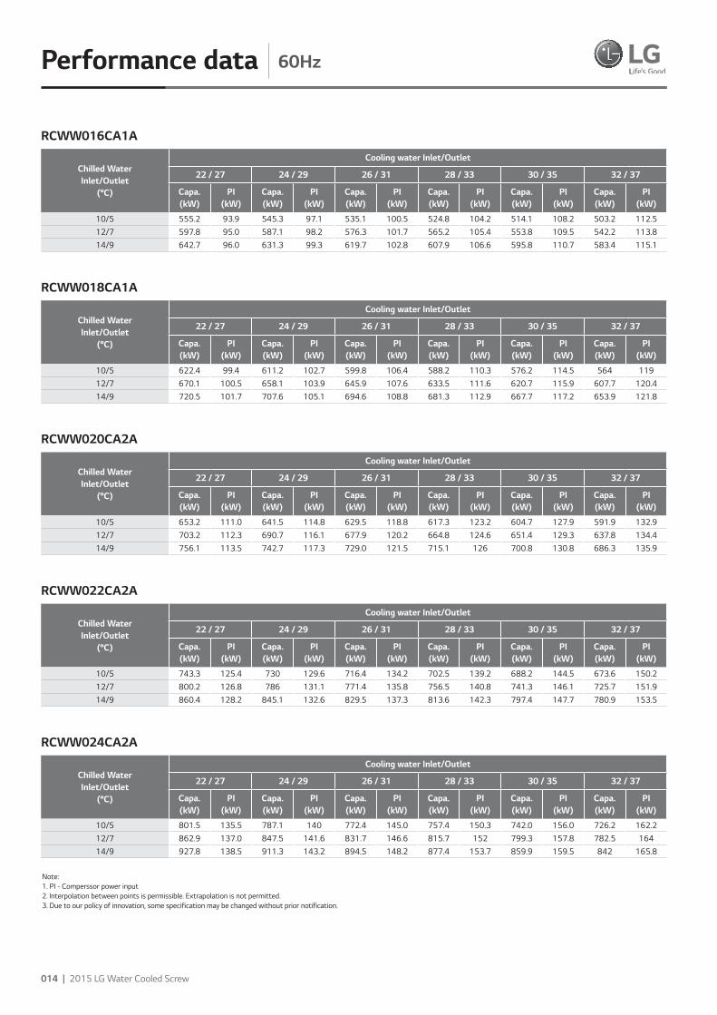
Performance data 60Hz
Chilled WaterInlet/Outlet
(°C)
Cooling water Inlet/Outlet
22 / 27 24 / 29 26 / 31 28 / 33 30 / 35 32 / 37
Capa.(kW)
PI(kW)
Capa.(kW)
PI(kW)
Capa.(kW)
PI(kW)
Capa.(kW)
PI(kW)
Capa.(kW)
PI(kW)
Capa.(kW)
PI(kW)
10/5 555.2 93.9 545.3 97.1 535.1 100.5 524.8 104.2 514.1 108.2 503.2 112.512/7 597.8 95.0 587.1 98.2 576.3 101.7 565.2 105.4 553.8 109.5 542.2 113.814/9 642.7 96.0 631.3 99.3 619.7 102.8 607.9 106.6 595.8 110.7 583.4 115.1
Chilled WaterInlet/Outlet
(°C)
Cooling water Inlet/Outlet
22 / 27 24 / 29 26 / 31 28 / 33 30 / 35 32 / 37
Capa.(kW)
PI(kW)
Capa.(kW)
PI(kW)
Capa.(kW)
PI(kW)
Capa.(kW)
PI(kW)
Capa.(kW)
PI(kW)
Capa.(kW)
PI(kW)
10/5 622.4 99.4 611.2 102.7 599.8 106.4 588.2 110.3 576.2 114.5 564 11912/7 670.1 100.5 658.1 103.9 645.9 107.6 633.5 111.6 620.7 115.9 607.7 120.414/9 720.5 101.7 707.6 105.1 694.6 108.8 681.3 112.9 667.7 117.2 653.9 121.8
Chilled WaterInlet/Outlet
(°C)
Cooling water Inlet/Outlet
22 / 27 24 / 29 26 / 31 28 / 33 30 / 35 32 / 37
Capa.(kW)
PI(kW)
Capa.(kW)
PI(kW)
Capa.(kW)
PI(kW)
Capa.(kW)
PI(kW)
Capa.(kW)
PI(kW)
Capa.(kW)
PI(kW)
10/5 653.2 111.0 641.5 114.8 629.5 118.8 617.3 123.2 604.7 127.9 591.9 132.912/7 703.2 112.3 690.7 116.1 677.9 120.2 664.8 124.6 651.4 129.3 637.8 134.414/9 756.1 113.5 742.7 117.3 729.0 121.5 715.1 126 700.8 130.8 686.3 135.9
Chilled WaterInlet/Outlet
(°C)
Cooling water Inlet/Outlet
22 / 27 24 / 29 26 / 31 28 / 33 30 / 35 32 / 37
Capa.(kW)
PI(kW)
Capa.(kW)
PI(kW)
Capa.(kW)
PI(kW)
Capa.(kW)
PI(kW)
Capa.(kW)
PI(kW)
Capa.(kW)
PI(kW)
10/5 743.3 125.4 730 129.6 716.4 134.2 702.5 139.2 688.2 144.5 673.6 150.212/7 800.2 126.8 786 131.1 771.4 135.8 756.5 140.8 741.3 146.1 725.7 151.914/9 860.4 128.2 845.1 132.6 829.5 137.3 813.6 142.3 797.4 147.7 780.9 153.5
Chilled WaterInlet/Outlet
(°C)
Cooling water Inlet/Outlet
22 / 27 24 / 29 26 / 31 28 / 33 30 / 35 32 / 37
Capa.(kW)
PI(kW)
Capa.(kW)
PI(kW)
Capa.(kW)
PI(kW)
Capa.(kW)
PI(kW)
Capa.(kW)
PI(kW)
Capa.(kW)
PI(kW)
10/5 801.5 135.5 787.1 140 772.4 145.0 757.4 150.3 742.0 156.0 726.2 162.212/7 862.9 137.0 847.5 141.6 831.7 146.6 815.7 152 799.3 157.8 782.5 16414/9 927.8 138.5 911.3 143.2 894.5 148.2 877.4 153.7 859.9 159.5 842 165.8
RCWW016CA1A
RCWW018CA1A
RCWW020CA2A
RCWW022CA2A
RCWW024CA2A
Note: 1. PI - Comperssor power input 2. Interpolation between points is permissible. Extrapolation is not permitted. 3. Due to our policy of innovation, some specification may be changed without prior notification.
2015 LG HVAC Solution | 015
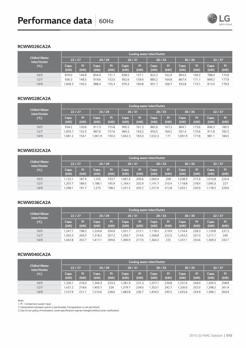
Performance data 60Hz
Chilled WaterInlet/Outlet
(°C)
Cooling water Inlet/Outlet
22 / 27 24 / 29 26 / 31 28 / 33 30 / 35 32 / 37
Capa.(kW)
PI(kW)
Capa.(kW)
PI(kW)
Capa.(kW)
PI(kW)
Capa.(kW)
PI(kW)
Capa.(kW)
PI(kW)
Capa.(kW)
PI(kW)
10/5 870.0 146.8 854.4 151.7 838.5 157.1 822.2 162.9 805.5 169.2 788.4 175.812/7 936.3 148.5 919.6 153.5 902.6 159.0 885.2 164.8 867.4 171.1 849.2 177.914/9 1,006.3 150.2 988.4 155.3 970.3 160.8 951.7 166.7 932.8 173.1 913.4 179.9
Chilled WaterInlet/Outlet
(°C)
Cooling water Inlet/Outlet
22 / 27 24 / 29 26 / 31 28 / 33 30 / 35 32 / 37
Capa.(kW)
PI(kW)
Capa.(kW)
PI(kW)
Capa.(kW)
PI(kW)
Capa.(kW)
PI(kW)
Capa.(kW)
PI(kW)
Capa.(kW)
PI(kW)
10/5 934.2 150.8 917.3 155.8 900.2 161.3 882.6 167.3 864.7 173.6 846.3 180.512/7 1,005.7 152.5 987.6 157.6 969.3 163.2 950.5 169.2 931.4 175.6 911.8 182.514/9 1,081.2 154.1 1,061.9 159.3 1,042.3 165.0 1,022.3 171 1,001.9 177.6 981.1 184.5
Chilled WaterInlet/Outlet
(°C)
Cooling water Inlet/Outlet
22 / 27 24 / 29 26 / 31 28 / 33 30 / 35 32 / 37
Capa.(kW)
PI(kW)
Capa.(kW)
PI(kW)
Capa.(kW)
PI(kW)
Capa.(kW)
PI(kW)
Capa.(kW)
PI(kW)
Capa.(kW)
PI(kW)
10/5 1,122.1 187.4 1,102 193.7 1,081.4 200.6 1,060.4 208 1,038.9 215.9 1,016.8 224.412/7 1,207.7 189.5 1,186.1 195.9 1,,164.1 202.9 1,141.7 210.4 1,118.8 218.4 1,095.3 22714/9 1,298.1 191.7 1,275 198.2 1,251.5 205.2 1,227.6 212.8 1,203.1 220.9 1,178.2 229.6
Chilled WaterInlet/Outlet
(°C)
Cooling water Inlet/Outlet
22 / 27 24 / 29 26 / 31 28 / 33 30 / 35 32 / 37
Capa.(kW)
PI(kW)
Capa.(kW)
PI(kW)
Capa.(kW)
PI(kW)
Capa.(kW)
PI(kW)
Capa.(kW)
PI(kW)
Capa.(kW)
PI(kW)
10/5 1,247.1 198.2 1,224.6 204.9 1,201.7 212.1 1,178.3 219.9 1,154.4 228.3 1,129.8 237.312/7 1,342.3 200.5 1,318.2 207.2 1,293.7 214.6 1,268.8 222.5 1,243.2 231.0 1,217.1 24014/9 1,442.8 202.7 1,417.1 209.6 1,390.9 217.0 1,364.3 225 1,337.1 233.6 1,309.3 242.7
Chilled WaterInlet/Outlet
(°C)
Cooling water Inlet/Outlet
22 / 27 24 / 29 26 / 31 28 / 33 30 / 35 32 / 37
Capa.(kW)
PI(kW)
Capa.(kW)
PI(kW)
Capa.(kW)
PI(kW)
Capa.(kW)
PI(kW)
Capa.(kW)
PI(kW)
Capa.(kW)
PI(kW)
10/5 1,330.1 216.0 1,306.3 223.3 1,281.9 231.3 1,257.1 239.8 1,231.6 249.0 1,205.5 258.812/7 1,431.2 218.6 1,405.7 226 1,379.7 234.0 1,353.1 242.7 1,326.0 252.0 1,298.2 261.914/9 1,537.9 221.1 1,510.6 228.6 1,482.8 236.7 1,454.5 245.5 1,425.6 254.9 1,396.1 264.9
RCWW026CA2A
RCWW028CA2A
RCWW032CA2A
RCWW036CA2A
RCWW040CA2A
Note: 1. PI - Comperssor power input 2. Interpolation between points is permissible. Extrapolation is not permitted. 3. Due to our policy of innovation, some specification may be changed without prior notification.
016 | 2015 LG Water Cooled Screw
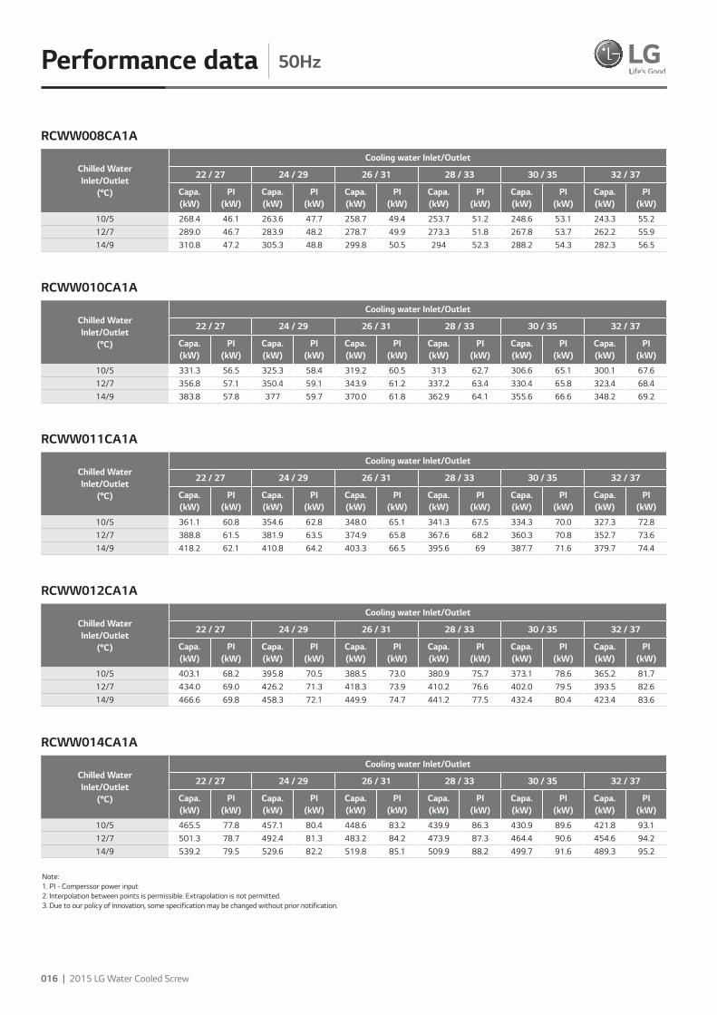
Performance data 50Hz
Chilled WaterInlet/Outlet
(°C)
Cooling water Inlet/Outlet
22 / 27 24 / 29 26 / 31 28 / 33 30 / 35 32 / 37
Capa.(kW)
PI(kW)
Capa.(kW)
PI(kW)
Capa.(kW)
PI(kW)
Capa.(kW)
PI(kW)
Capa.(kW)
PI(kW)
Capa.(kW)
PI(kW)
10/5 268.4 46.1 263.6 47.7 258.7 49.4 253.7 51.2 248.6 53.1 243.3 55.212/7 289.0 46.7 283.9 48.2 278.7 49.9 273.3 51.8 267.8 53.7 262.2 55.914/9 310.8 47.2 305.3 48.8 299.8 50.5 294 52.3 288.2 54.3 282.3 56.5
Chilled WaterInlet/Outlet
(°C)
Cooling water Inlet/Outlet
22 / 27 24 / 29 26 / 31 28 / 33 30 / 35 32 / 37
Capa.(kW)
PI(kW)
Capa.(kW)
PI(kW)
Capa.(kW)
PI(kW)
Capa.(kW)
PI(kW)
Capa.(kW)
PI(kW)
Capa.(kW)
PI(kW)
10/5 331.3 56.5 325.3 58.4 319.2 60.5 313 62.7 306.6 65.1 300.1 67.612/7 356.8 57.1 350.4 59.1 343.9 61.2 337.2 63.4 330.4 65.8 323.4 68.414/9 383.8 57.8 377 59.7 370.0 61.8 362.9 64.1 355.6 66.6 348.2 69.2
Chilled WaterInlet/Outlet
(°C)
Cooling water Inlet/Outlet
22 / 27 24 / 29 26 / 31 28 / 33 30 / 35 32 / 37
Capa.(kW)
PI(kW)
Capa.(kW)
PI(kW)
Capa.(kW)
PI(kW)
Capa.(kW)
PI(kW)
Capa.(kW)
PI(kW)
Capa.(kW)
PI(kW)
10/5 361.1 60.8 354.6 62.8 348.0 65.1 341.3 67.5 334.3 70.0 327.3 72.812/7 388.8 61.5 381.9 63.5 374.9 65.8 367.6 68.2 360.3 70.8 352.7 73.614/9 418.2 62.1 410.8 64.2 403.3 66.5 395.6 69 387.7 71.6 379.7 74.4
Chilled WaterInlet/Outlet
(°C)
Cooling water Inlet/Outlet
22 / 27 24 / 29 26 / 31 28 / 33 30 / 35 32 / 37
Capa.(kW)
PI(kW)
Capa.(kW)
PI(kW)
Capa.(kW)
PI(kW)
Capa.(kW)
PI(kW)
Capa.(kW)
PI(kW)
Capa.(kW)
PI(kW)
10/5 403.1 68.2 395.8 70.5 388.5 73.0 380.9 75.7 373.1 78.6 365.2 81.712/7 434.0 69.0 426.2 71.3 418.3 73.9 410.2 76.6 402.0 79.5 393.5 82.614/9 466.6 69.8 458.3 72.1 449.9 74.7 441.2 77.5 432.4 80.4 423.4 83.6
Chilled WaterInlet/Outlet
(°C)
Cooling water Inlet/Outlet
22 / 27 24 / 29 26 / 31 28 / 33 30 / 35 32 / 37
Capa.(kW)
PI(kW)
Capa.(kW)
PI(kW)
Capa.(kW)
PI(kW)
Capa.(kW)
PI(kW)
Capa.(kW)
PI(kW)
Capa.(kW)
PI(kW)
10/5 465.5 77.8 457.1 80.4 448.6 83.2 439.9 86.3 430.9 89.6 421.8 93.112/7 501.3 78.7 492.4 81.3 483.2 84.2 473.9 87.3 464.4 90.6 454.6 94.214/9 539.2 79.5 529.6 82.2 519.8 85.1 509.9 88.2 499.7 91.6 489.3 95.2
RCWW008CA1A
RCWW010CA1A
RCWW011CA1A
RCWW012CA1A
RCWW014CA1A
Note: 1. PI - Comperssor power input 2. Interpolation between points is permissible. Extrapolation is not permitted. 3. Due to our policy of innovation, some specification may be changed without prior notification.
2015 LG HVAC Solution | 017
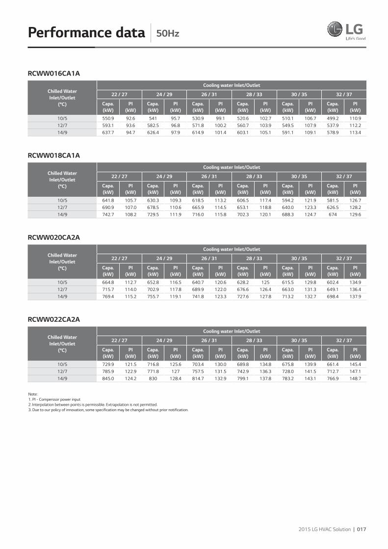
Performance data 50Hz
Chilled WaterInlet/Outlet
(°C)
Cooling water Inlet/Outlet
22 / 27 24 / 29 26 / 31 28 / 33 30 / 35 32 / 37
Capa.(kW)
PI(kW)
Capa.(kW)
PI(kW)
Capa.(kW)
PI(kW)
Capa.(kW)
PI(kW)
Capa.(kW)
PI(kW)
Capa.(kW)
PI(kW)
10/5 550.9 92.6 541 95.7 530.9 99.1 520.6 102.7 510.1 106.7 499.2 110.912/7 593.1 93.6 582.5 96.8 571.8 100.2 560.7 103.9 549.5 107.9 537.9 112.214/9 637.7 94.7 626.4 97.9 614.9 101.4 603.1 105.1 591.1 109.1 578.9 113.4
Chilled WaterInlet/Outlet
(°C)
Cooling water Inlet/Outlet
22 / 27 24 / 29 26 / 31 28 / 33 30 / 35 32 / 37
Capa.(kW)
PI(kW)
Capa.(kW)
PI(kW)
Capa.(kW)
PI(kW)
Capa.(kW)
PI(kW)
Capa.(kW)
PI(kW)
Capa.(kW)
PI(kW)
10/5 641.8 105.7 630.3 109.3 618.5 113.2 606.5 117.4 594.2 121.9 581.5 126.712/7 690.9 107.0 678.5 110.6 665.9 114.5 653.1 118.8 640.0 123.3 626.5 128.214/9 742.7 108.2 729.5 111.9 716.0 115.8 702.3 120.1 688.3 124.7 674 129.6
Chilled WaterInlet/Outlet
(°C)
Cooling water Inlet/Outlet
22 / 27 24 / 29 26 / 31 28 / 33 30 / 35 32 / 37
Capa.(kW)
PI(kW)
Capa.(kW)
PI(kW)
Capa.(kW)
PI(kW)
Capa.(kW)
PI(kW)
Capa.(kW)
PI(kW)
Capa.(kW)
PI(kW)
10/5 664.8 112.7 652.8 116.5 640.7 120.6 628.2 125 615.5 129.8 602.4 134.912/7 715.7 114.0 702.9 117.8 689.9 122.0 676.6 126.4 663.0 131.3 649.1 136.414/9 769.4 115.2 755.7 119.1 741.8 123.3 727.6 127.8 713.2 132.7 698.4 137.9
Chilled WaterInlet/Outlet
(°C)
Cooling water Inlet/Outlet
22 / 27 24 / 29 26 / 31 28 / 33 30 / 35 32 / 37
Capa.(kW)
PI(kW)
Capa.(kW)
PI(kW)
Capa.(kW)
PI(kW)
Capa.(kW)
PI(kW)
Capa.(kW)
PI(kW)
Capa.(kW)
PI(kW)
10/5 729.9 121.5 716.8 125.6 703.4 130.0 689.8 134.8 675.8 139.9 661.4 145.412/7 785.9 122.9 771.8 127 757.5 131.5 742.9 136.3 728.0 141.5 712.7 147.114/9 845.0 124.2 830 128.4 814.7 132.9 799.1 137.8 783.2 143.1 766.9 148.7
RCWW016CA1A
RCWW018CA1A
RCWW020CA2A
RCWW022CA2A
Note: 1. PI - Comperssor power input 2. Interpolation between points is permissible. Extrapolation is not permitted. 3. Due to our policy of innovation, some specification may be changed without prior notification.
018 | 2015 LG Water Cooled Screw
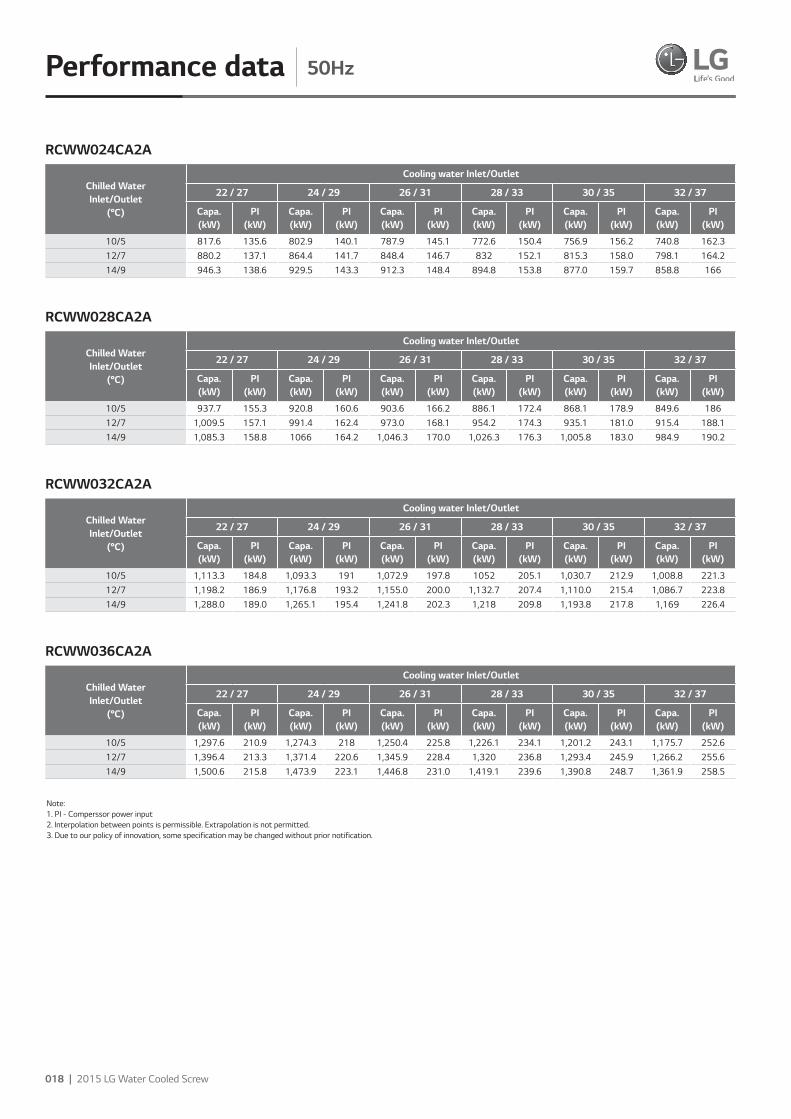
Performance data 50Hz
Chilled WaterInlet/Outlet
(°C)
Cooling water Inlet/Outlet
22 / 27 24 / 29 26 / 31 28 / 33 30 / 35 32 / 37
Capa.(kW)
PI(kW)
Capa.(kW)
PI(kW)
Capa.(kW)
PI(kW)
Capa.(kW)
PI(kW)
Capa.(kW)
PI(kW)
Capa.(kW)
PI(kW)
10/5 817.6 135.6 802.9 140.1 787.9 145.1 772.6 150.4 756.9 156.2 740.8 162.312/7 880.2 137.1 864.4 141.7 848.4 146.7 832 152.1 815.3 158.0 798.1 164.214/9 946.3 138.6 929.5 143.3 912.3 148.4 894.8 153.8 877.0 159.7 858.8 166
RCWW024CA2A
Chilled WaterInlet/Outlet
(°C)
Cooling water Inlet/Outlet
22 / 27 24 / 29 26 / 31 28 / 33 30 / 35 32 / 37
Capa.(kW)
PI(kW)
Capa.(kW)
PI(kW)
Capa.(kW)
PI(kW)
Capa.(kW)
PI(kW)
Capa.(kW)
PI(kW)
Capa.(kW)
PI(kW)
10/5 937.7 155.3 920.8 160.6 903.6 166.2 886.1 172.4 868.1 178.9 849.6 18612/7 1,009.5 157.1 991.4 162.4 973.0 168.1 954.2 174.3 935.1 181.0 915.4 188.114/9 1,085.3 158.8 1066 164.2 1,046.3 170.0 1,026.3 176.3 1,005.8 183.0 984.9 190.2
Chilled WaterInlet/Outlet
(°C)
Cooling water Inlet/Outlet
22 / 27 24 / 29 26 / 31 28 / 33 30 / 35 32 / 37
Capa.(kW)
PI(kW)
Capa.(kW)
PI(kW)
Capa.(kW)
PI(kW)
Capa.(kW)
PI(kW)
Capa.(kW)
PI(kW)
Capa.(kW)
PI(kW)
10/5 1,113.3 184.8 1,093.3 191 1,072.9 197.8 1052 205.1 1,030.7 212.9 1,008.8 221.312/7 1,198.2 186.9 1,176.8 193.2 1,155.0 200.0 1,132.7 207.4 1,110.0 215.4 1,086.7 223.814/9 1,288.0 189.0 1,265.1 195.4 1,241.8 202.3 1,218 209.8 1,193.8 217.8 1,169 226.4
Chilled WaterInlet/Outlet
(°C)
Cooling water Inlet/Outlet
22 / 27 24 / 29 26 / 31 28 / 33 30 / 35 32 / 37
Capa.(kW)
PI(kW)
Capa.(kW)
PI(kW)
Capa.(kW)
PI(kW)
Capa.(kW)
PI(kW)
Capa.(kW)
PI(kW)
Capa.(kW)
PI(kW)
10/5 1,297.6 210.9 1,274.3 218 1,250.4 225.8 1,226.1 234.1 1,201.2 243.1 1,175.7 252.612/7 1,396.4 213.3 1,371.4 220.6 1,345.9 228.4 1,320 236.8 1,293.4 245.9 1,266.2 255.614/9 1,500.6 215.8 1,473.9 223.1 1,446.8 231.0 1,419.1 239.6 1,390.8 248.7 1,361.9 258.5
RCWW028CA2A
RCWW032CA2A
RCWW036CA2A
Note: 1. PI - Comperssor power input 2. Interpolation between points is permissible. Extrapolation is not permitted. 3. Due to our policy of innovation, some specification may be changed without prior notification.
2015 LG HVAC Solution | 019
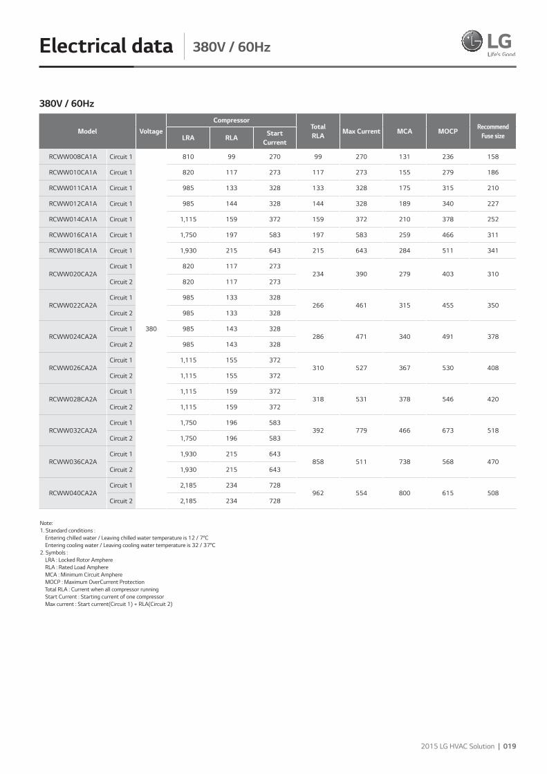
Electrical data 380V / 60Hz
Model VoltageCompressor
TotalRLA
Max Current MCA MOCPRecommend
Fuse sizeLRA RLAStart
Current
RCWW008CA1A Circuit 1
380
810 99 270 99 270 131 236 158
RCWW010CA1A Circuit 1 820 117 273 117 273 155 279 186
RCWW011CA1A Circuit 1 985 133 328 133 328 175 315 210
RCWW012CA1A Circuit 1 985 144 328 144 328 189 340 227
RCWW014CA1A Circuit 1 1,115 159 372 159 372 210 378 252
RCWW016CA1A Circuit 1 1,750 197 583 197 583 259 466 311
RCWW018CA1A Circuit 1 1,930 215 643 215 643 284 511 341
RCWW020CA2ACircuit 1 820 117 273
234 390 279 403 310 Circuit 2 820 117 273
RCWW022CA2ACircuit 1 985 133 328
266 461 315 455 350 Circuit 2 985 133 328
RCWW024CA2ACircuit 1 985 143 328
286 471 340 491 378 Circuit 2 985 143 328
RCWW026CA2ACircuit 1 1,115 155 372
310 527 367 530 408 Circuit 2 1,115 155 372
RCWW028CA2ACircuit 1 1,115 159 372
318 531 378 546 420 Circuit 2 1,115 159 372
RCWW032CA2ACircuit 1 1,750 196 583
392 779 466 673 518 Circuit 2 1,750 196 583
RCWW036CA2ACircuit 1 1,930 215 643
858 511 738 568 470 Circuit 2 1,930 215 643
RCWW040CA2ACircuit 1 2,185 234 728
962 554 800 615 508 Circuit 2 2,185 234 728
380V / 60Hz
Note: 1. Standard conditions : Entering chilled water / Leaving chilled water temperature is 12 / 7°C Entering cooling water / Leaving cooling water temperature is 32 / 37°C2. Symbols : LRA : Locked Rotor Amphere RLA : Rated Load Amphere MCA : Minimum Circuit Amphere MOCP : Maximum OverCurrent Protection Total RLA : Current when all compressor running Start Current : Starting current of one compressor Max current : Start current(Circuit 1) + RLA(Circuit 2)
020 | 2015 LG Water Cooled Screw
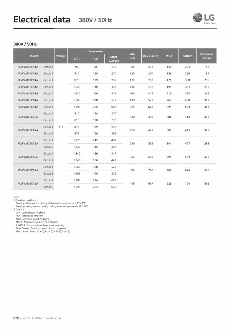
Electrical data 380V / 50Hz
Model VoltageCompressor
TotalRLA
Max Current MCA MOCPRecommend
Fuse sizeLRA RLAStart
Current
RCWW008CA1A Circuit 1
415
700 98 233 98 233 130 234 156
RCWW010CA1A Circuit 1 810 120 270 120 270 159 286 191
RCWW011CA1A Circuit 1 875 129 292 129 292 171 308 206
RCWW012CA1A Circuit 1 1,220 146 407 146 407 191 344 230
RCWW014CA1A Circuit 1 1,340 166 447 166 447 219 394 263
RCWW016CA1A Circuit 1 1,565 198 522 198 522 260 468 312
RCWW018CA1A Circuit 1 1,990 225 663 225 663 294 529 353
RCWW020CA2ACircuit 1 810 120 270
240 390 286 413 318 Circuit 2 810 120 270
RCWW022CA2ACircuit 1 875 129 292
258 421 308 445 343 Circuit 2 875 129 292
RCWW024CA2ACircuit 1 1,220 145 407
290 552 344 497 383 Circuit 2 1,220 145 407
RCWW028CA2ACircuit 1 1,340 166 447
332 613 394 569 438 Circuit 2 1,340 166 447
RCWW032CA2ACircuit 1 1,565 198 522
396 720 468 676 520 Circuit 2 1,565 198 522
RCWW036CA2ACircuit 1 1,990 224 663
448 887 529 764 588 Circuit 2 1,990 224 663
380V / 50Hz
Note: 1. Standard conditions : Entering chilled water / Leaving chilled water temperature is 12 / 7°C Entering cooling water / Leaving cooling water temperature is 32 / 37°C2. Symbols : LRA : Locked Rotor Amphere RLA : Rated Load Amphere MCA : Minimum Circuit Amphere MOCP : Maximum OverCurrent Protection Total RLA : Current when all compressor running Start Current : Starting current of one compressor Max current : Start current(Circuit 1) + RLA(Circuit 2)
2015 LG HVAC Solution | 021
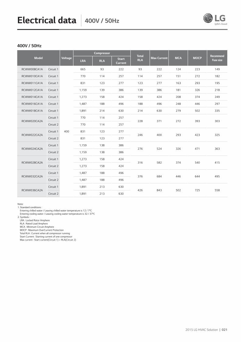
Electrical data 400V / 50Hz
Model VoltageCompressor
TotalRLA
Max Current MCA MOCPRecommend
Fuse sizeLRA RLAStart
Current
RCWW008CA1A Circuit 1
400
665 93 222 93 222 124 223 149
RCWW010CA1A Circuit 1 770 114 257 114 257 151 272 182
RCWW011CA1A Circuit 1 831 123 277 123 277 163 293 195
RCWW012CA1A Circuit 1 1,159 139 386 139 386 181 326 218
RCWW014CA1A Circuit 1 1,273 158 424 158 424 208 374 249
RCWW016CA1A Circuit 1 1,487 188 496 188 496 248 446 297
RCWW018CA1A Circuit 1 1,891 214 630 214 630 279 502 335
RCWW020CA2ACircuit 1 770 114 257
228 371 272 393 303 Circuit 2 770 114 257
RCWW022CA2ACircuit 1 831 123 277
246 400 293 423 325 Circuit 2 831 123 277
RCWW024CA2ACircuit 1 1,159 138 386
276 524 326 471 363 Circuit 2 1,159 138 386
RCWW028CA2ACircuit 1 1,273 158 424
316 582 374 540 415 Circuit 2 1,273 158 424
RCWW032CA2ACircuit 1 1,487 188 496
376 684 446 644 495 Circuit 2 1,487 188 496
RCWW036CA2ACircuit 1 1,891 213 630
426 843 502 725 558 Circuit 2 1,891 213 630
400V / 50Hz
Note: 1. Standard conditions : Entering chilled water / Leaving chilled water temperature is 12 / 7°C Entering cooling water / Leaving cooling water temperature is 32 / 37°C2. Symbols : LRA : Locked Rotor Amphere RLA : Rated Load Amphere MCA : Minimum Circuit Amphere MOCP : Maximum OverCurrent Protection Total RLA : Current when all compressor running Start Current : Starting current of one compressor Max current : Start current(Circuit 1) + RLA(Circuit 2)
022 | 2015 LG Water Cooled Screw
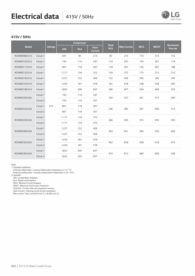
Electrical data 415V / 50Hz
Model VoltageCompressor
TotalRLA
Max Current MCA MOCPRecommend
Fuse sizeLRA RLAStart
Current
RCWW008CA1A Circuit 1
415
641 90 214 90 214 119 214 143
RCWW010CA1A Circuit 1 742 110 247 110 247 145 261 174
RCWW011CA1A Circuit 1 801 118 267 118 267 156 281 188
RCWW012CA1A Circuit 1 1,117 134 372 134 372 175 315 210
RCWW014CA1A Circuit 1 1,227 152 409 152 409 200 360 240
RCWW016CA1A Circuit 1 1,433 181 478 181 478 238 428 285
RCWW018CA1A Circuit 1 1,822 206 607 206 607 269 484 323
RCWW020CA2ACircuit 1 742 110 247
220 357 261 377 290 Circuit 2 742 110 247
RCWW022CA2ACircuit 1 801 118 267
236 385 281 406 313 Circuit 2 801 118 267
RCWW024CA2ACircuit 1 1,117 133 372
266 505 315 455 350 Circuit 2 1,117 133 372
RCWW028CA2ACircuit 1 1,227 152 409
304 561 360 520 400 Circuit 2 1,227 152 409
RCWW032CA2ACircuit 1 1,433 181 478
362 659 428 618 475 Circuit 2 1,433 181 478
RCWW036CA2ACircuit 1 1,822 205 607
410 812 484 699 538 Circuit 2 1,822 205 607
415V / 50Hz
Note: 1. Standard conditions : Entering chilled water / Leaving chilled water temperature is 12 / 7°C Entering cooling water / Leaving cooling water temperature is 32 / 37°C2. Symbols : LRA : Locked Rotor Amphere RLA : Rated Load Amphere MCA : Minimum Circuit Amphere MOCP : Maximum OverCurrent Protection Total RLA : Current when all compressor running Start Current : Starting current of one compressor Max current : Start current(Circuit 1) + RLA(Circuit 2)

2015 LG HVAC Solution | 023
Electrical data 440V / 60Hz
Model VoltageCompressor
TotalRLA
Max Current MCA MOCPRecommend
Fuse sizeLRA RLAStart
Current
RCWW008CA1A Circuit 1
440
700 86 233 86 233 114 205 137
RCWW010CA1A Circuit 1 708 101 236 101 236 134 241 161
RCWW011CA1A Circuit 1 851 115 284 115 284 151 272 182
RCWW012CA1A Circuit 1 851 124 284 124 284 163 293 195
RCWW014CA1A Circuit 1 963 137 321 137 321 181 326 218
RCWW016CA1A Circuit 1 1,511 170 504 170 504 224 403 269
RCWW018CA1A Circuit 1 1,667 186 556 186 556 245 441 294
RCWW020CA2ACircuit 1 708 101 236
202 337 241 348 268 Circuit 2 708 101 236
RCWW022CA2ACircuit 1 851 115 284
230 399 272 393 303 Circuit 2 851 115 284
RCWW024CA2ACircuit 1 851 124 284
248 408 293 423 325 Circuit 2 851 124 284
RCWW026CA2ACircuit 1 963 134 321
268 455 317 458 353 Circuit 2 963 134 321
RCWW028CA2ACircuit 1 963 137 321
274 458 326 471 363 Circuit 2 963 137 321
RCWW032CA2ACircuit 1 1,511 169 504
338 673 403 582 448 Circuit 2 1,511 169 504
RCWW036CA2ACircuit 1 1,667 186 556
372 742 441 637 490 Circuit 2 1,667 186 556
RCWW040CA2ACircuit 1 1,887 202 629
831 477 689 530 488 Circuit 2 1,887 202 629
440V / 60Hz
Note: 1. Standard conditions : Entering chilled water / Leaving chilled water temperature is 12 / 7°C Entering cooling water / Leaving cooling water temperature is 32 / 37°C2. Symbols : LRA : Locked Rotor Amphere RLA : Rated Load Amphere MCA : Minimum Circuit Amphere MOCP : Maximum OverCurrent Protection Total RLA : Current when all compressor running Start Current : Starting current of one compressor Max current : Start current(Circuit 1) + RLA(Circuit 2)
024 | 2015 LG Water Cooled Screw
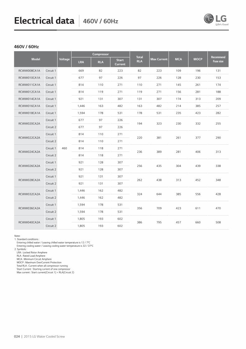
Electrical data 460V / 60Hz
Model VoltageCompressor
TotalRLA
Max Current MCA MOCPRecommend
Fuse sizeLRA RLAStart
Current
RCWW008CA1A Circuit 1
460
669 82 223 82 223 109 196 131
RCWW010CA1A Circuit 1 677 97 226 97 226 128 230 153
RCWW011CA1A Circuit 1 814 110 271 110 271 145 261 174
RCWW012CA1A Circuit 1 814 119 271 119 271 156 281 188
RCWW014CA1A Circuit 1 921 131 307 131 307 174 313 209
RCWW016CA1A Circuit 1 1,446 163 482 163 482 214 385 257
RCWW018CA1A Circuit 1 1,594 178 531 178 531 235 423 282
RCWW020CA2ACircuit 1 677 97 226
194 323 230 332 255 Circuit 2 677 97 226
RCWW022CA2ACircuit 1 814 110 271
220 381 261 377 290 Circuit 2 814 110 271
RCWW024CA2ACircuit 1 814 118 271
236 389 281 406 313 Circuit 2 814 118 271
RCWW026CA2ACircuit 1 921 128 307
256 435 304 439 338 Circuit 2 921 128 307
RCWW028CA2ACircuit 1 921 131 307
262 438 313 452 348 Circuit 2 921 131 307
RCWW032CA2ACircuit 1 1,446 162 482
324 644 385 556 428 Circuit 2 1,446 162 482
RCWW036CA2ACircuit 1 1,594 178 531
356 709 423 611 470 Circuit 2 1,594 178 531
RCWW040CA2ACircuit 1 1,805 193 602
386 795 457 660 508 Circuit 2 1,805 193 602
460V / 60Hz
Note: 1. Standard conditions : Entering chilled water / Leaving chilled water temperature is 12 / 7°C Entering cooling water / Leaving cooling water temperature is 32 / 37°C2. Symbols : LRA : Locked Rotor Amphere RLA : Rated Load Amphere MCA : Minimum Circuit Amphere MOCP : Maximum OverCurrent Protection Total RLA : Current when all compressor running Start Current : Starting current of one compressor Max current : Start current(Circuit 1) + RLA(Circuit 2)

2015 LG HVAC Solution | 025
Electrical data 480V / 60Hz
Model VoltageCompressor
TotalRLA
Max Current MCA MOCPRecommend
Fuse sizeLRA RLAStart
Current
RCWW008CA1A Circuit 1
480
641 78 214 78 214 104 187 125
RCWW010CA1A Circuit 1 649 93 216 93 216 123 221 147
RCWW011CA1A Circuit 1 780 105 260 105 260 139 250 167
RCWW012CA1A Circuit 1 780 114 260 114 260 150 270 180
RCWW014CA1A Circuit 1 883 126 294 126 294 166 299 200
RCWW016CA1A Circuit 1 1,385 156 462 156 462 205 369 246
RCWW018CA1A Circuit 1 1,528 170 509 170 509 225 405 270
RCWW020CA2ACircuit 1 649 93 216
186 309 221 319 245 Circuit 2 649 93 216
RCWW022CA2ACircuit 1 780 105 260
210 365 250 361 278 Circuit 2 780 105 260
RCWW024CA2ACircuit 1 780 113 260
226 373 270 390 300 Circuit 2 780 113 260
RCWW026CA2ACircuit 1 883 123 294
246 417 290 419 323 Circuit 2 883 123 294
RCWW028CA2ACircuit 1 883 126 294
252 420 299 432 333 Circuit 2 883 126 294
RCWW032CA2ACircuit 1 1,385 155 462
310 617 369 533 410 Circuit 2 1,385 155 462
RCWW036CA2ACircuit 1 1,528 170 509
340 679 405 585 450 Circuit 2 1,528 170 509
RCWW040CA2ACircuit 1 1,730 185 577
370 762 439 634 488 Circuit 2 1,730 185 577
480V / 60Hz
Note: 1. Standard conditions : Entering chilled water / Leaving chilled water temperature is 12 / 7°C Entering cooling water / Leaving cooling water temperature is 32 / 37°C2. Symbols : LRA : Locked Rotor Amphere RLA : Rated Load Amphere MCA : Minimum Circuit Amphere MOCP : Maximum OverCurrent Protection Total RLA : Current when all compressor running Start Current : Starting current of one compressor Max current : Start current(Circuit 1) + RLA(Circuit 2)
026 | 2015 LG Water Cooled Screw
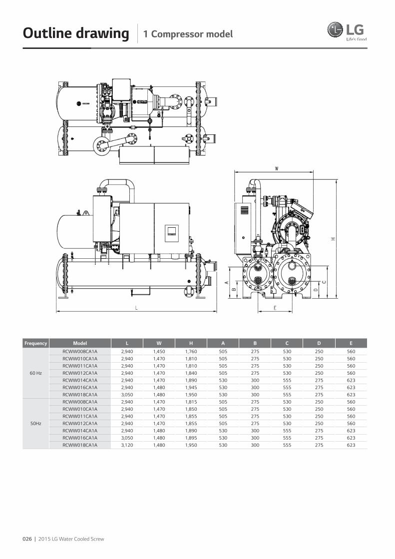
1 Compressor modelOutline drawing
Frequency Model L W H A B C D E
60 Hz
RCWW008CA1A 2,940 1,450 1,760 505 275 530 250 560RCWW010CA1A 2,940 1,470 1,810 505 275 530 250 560RCWW011CA1A 2,940 1,470 1,810 505 275 530 250 560RCWW012CA1A 2,940 1,470 1,840 505 275 530 250 560RCWW014CA1A 2,940 1,470 1,890 530 300 555 275 623RCWW016CA1A 2,940 1,480 1,945 530 300 555 275 623RCWW018CA1A 3,050 1,480 1,950 530 300 555 275 623
50Hz
RCWW008CA1A 2,940 1,470 1,815 505 275 530 250 560RCWW010CA1A 2,940 1,470 1,850 505 275 530 250 560RCWW011CA1A 2,940 1,470 1,855 505 275 530 250 560RCWW012CA1A 2,940 1,470 1,855 505 275 530 250 560RCWW014CA1A 2,940 1,480 1,890 530 300 555 275 623RCWW016CA1A 3,050 1,480 1,895 530 300 555 275 623RCWW018CA1A 3,120 1,480 1,950 530 300 555 275 623
2015 LG HVAC Solution | 027
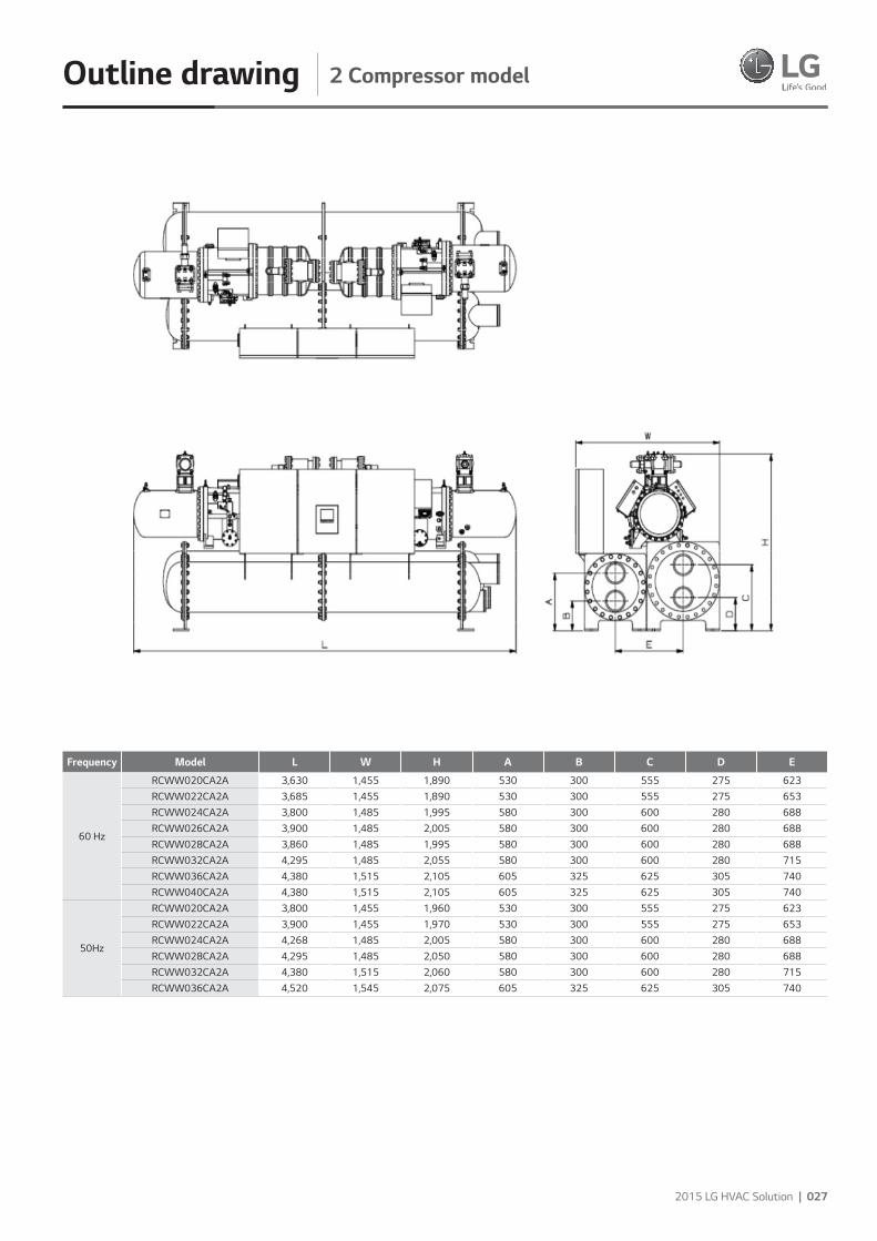
2 Compressor modelOutline drawing
Frequency Model L W H A B C D E
60 Hz
RCWW020CA2A 3,630 1,455 1,890 530 300 555 275 623RCWW022CA2A 3,685 1,455 1,890 530 300 555 275 653RCWW024CA2A 3,800 1,485 1,995 580 300 600 280 688RCWW026CA2A 3,900 1,485 2,005 580 300 600 280 688RCWW028CA2A 3,860 1,485 1,995 580 300 600 280 688RCWW032CA2A 4,295 1,485 2,055 580 300 600 280 715RCWW036CA2A 4,380 1,515 2,105 605 325 625 305 740RCWW040CA2A 4,380 1,515 2,105 605 325 625 305 740
50Hz
RCWW020CA2A 3,800 1,455 1,960 530 300 555 275 623RCWW022CA2A 3,900 1,455 1,970 530 300 555 275 653RCWW024CA2A 4,268 1,485 2,005 580 300 600 280 688RCWW028CA2A 4,295 1,485 2,050 580 300 600 280 688RCWW032CA2A 4,380 1,515 2,060 580 300 600 280 715RCWW036CA2A 4,520 1,545 2,075 605 325 625 305 740
028 | 2015 LG Water Cooled Screw
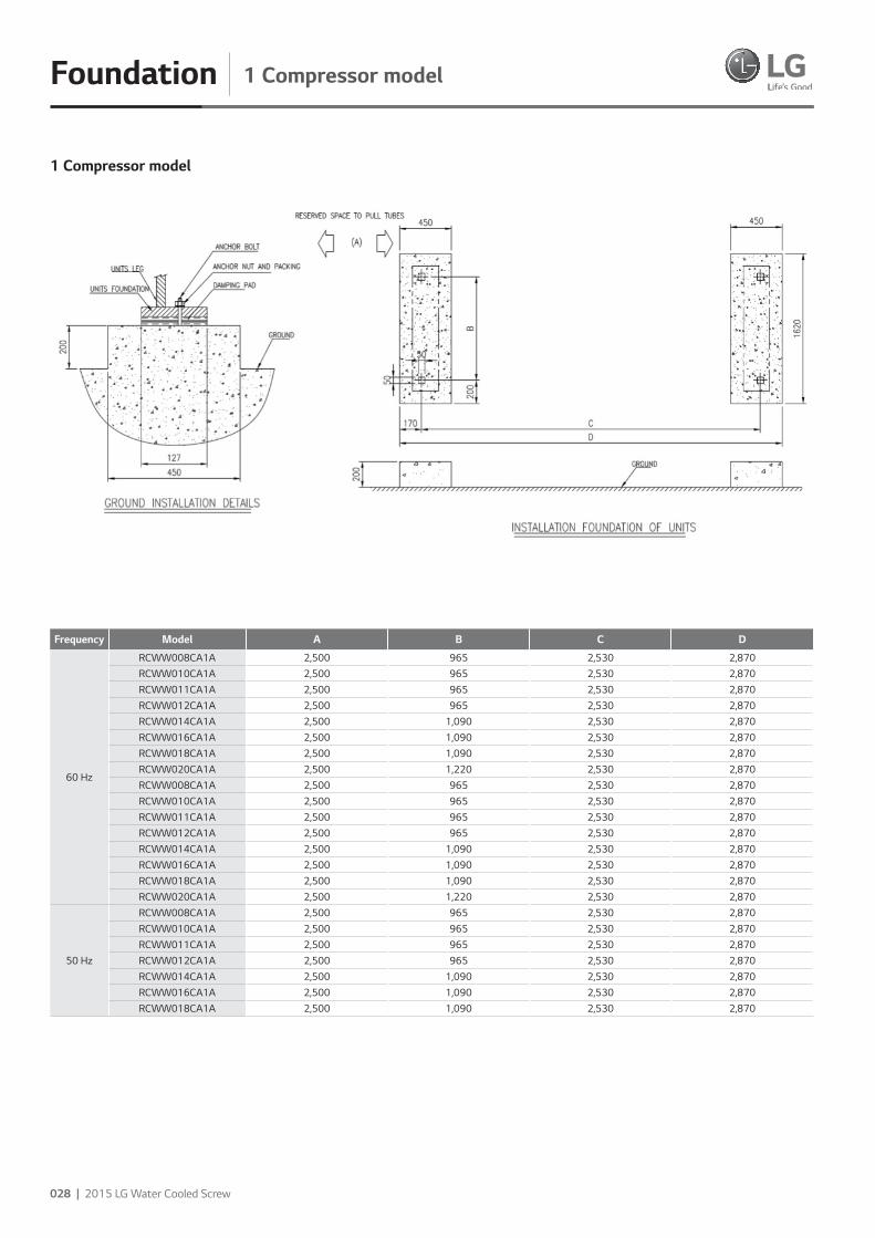
1 Compressor modelFoundation
1 Compressor model
Frequency Model A B C D
60 Hz
RCWW008CA1A 2,500 965 2,530 2,870RCWW010CA1A 2,500 965 2,530 2,870RCWW011CA1A 2,500 965 2,530 2,870RCWW012CA1A 2,500 965 2,530 2,870RCWW014CA1A 2,500 1,090 2,530 2,870RCWW016CA1A 2,500 1,090 2,530 2,870RCWW018CA1A 2,500 1,090 2,530 2,870RCWW020CA1A 2,500 1,220 2,530 2,870RCWW008CA1A 2,500 965 2,530 2,870RCWW010CA1A 2,500 965 2,530 2,870RCWW011CA1A 2,500 965 2,530 2,870RCWW012CA1A 2,500 965 2,530 2,870RCWW014CA1A 2,500 1,090 2,530 2,870RCWW016CA1A 2,500 1,090 2,530 2,870RCWW018CA1A 2,500 1,090 2,530 2,870RCWW020CA1A 2,500 1,220 2,530 2,870
50 Hz
RCWW008CA1A 2,500 965 2,530 2,870RCWW010CA1A 2,500 965 2,530 2,870RCWW011CA1A 2,500 965 2,530 2,870RCWW012CA1A 2,500 965 2,530 2,870RCWW014CA1A 2,500 1,090 2,530 2,870RCWW016CA1A 2,500 1,090 2,530 2,870RCWW018CA1A 2,500 1,090 2,530 2,870
2015 LG HVAC Solution | 029
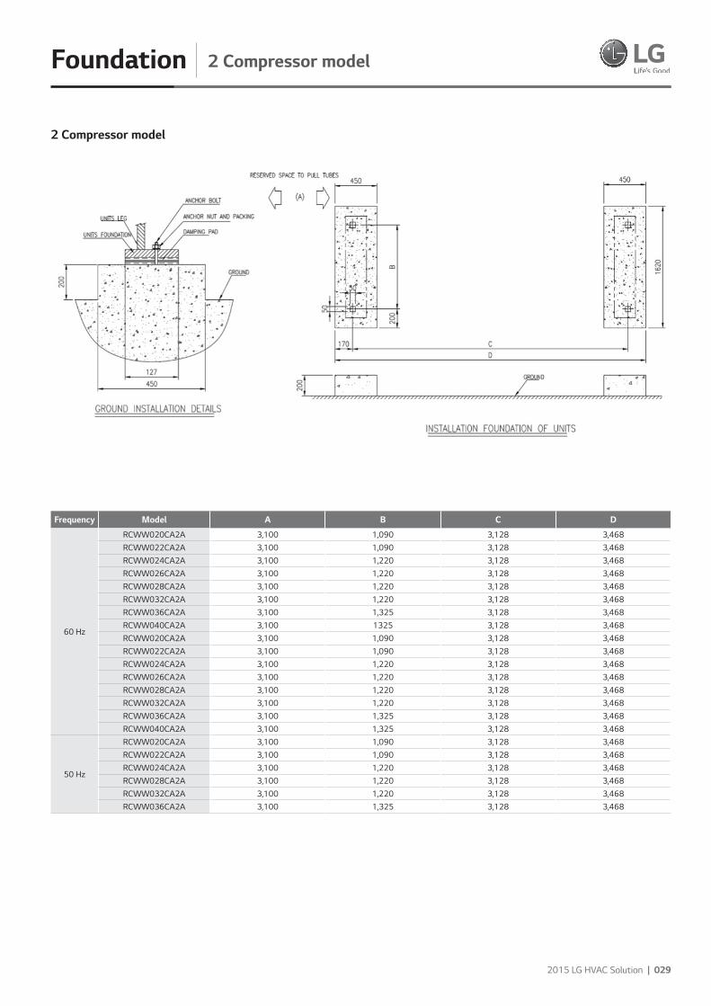
2 Compressor modelFoundation
2 Compressor model
Frequency Model A B C D
60 Hz
RCWW020CA2A 3,100 1,090 3,128 3,468RCWW022CA2A 3,100 1,090 3,128 3,468RCWW024CA2A 3,100 1,220 3,128 3,468RCWW026CA2A 3,100 1,220 3,128 3,468RCWW028CA2A 3,100 1,220 3,128 3,468RCWW032CA2A 3,100 1,220 3,128 3,468RCWW036CA2A 3,100 1,325 3,128 3,468RCWW040CA2A 3,100 1325 3,128 3,468RCWW020CA2A 3,100 1,090 3,128 3,468RCWW022CA2A 3,100 1,090 3,128 3,468RCWW024CA2A 3,100 1,220 3,128 3,468RCWW026CA2A 3,100 1,220 3,128 3,468RCWW028CA2A 3,100 1,220 3,128 3,468RCWW032CA2A 3,100 1,220 3,128 3,468RCWW036CA2A 3,100 1,325 3,128 3,468RCWW040CA2A 3,100 1,325 3,128 3,468
50 Hz
RCWW020CA2A 3,100 1,090 3,128 3,468RCWW022CA2A 3,100 1,090 3,128 3,468RCWW024CA2A 3,100 1,220 3,128 3,468RCWW028CA2A 3,100 1,220 3,128 3,468RCWW032CA2A 3,100 1,220 3,128 3,468RCWW036CA2A 3,100 1,325 3,128 3,468
030 | 2015 LG Water Cooled Screw
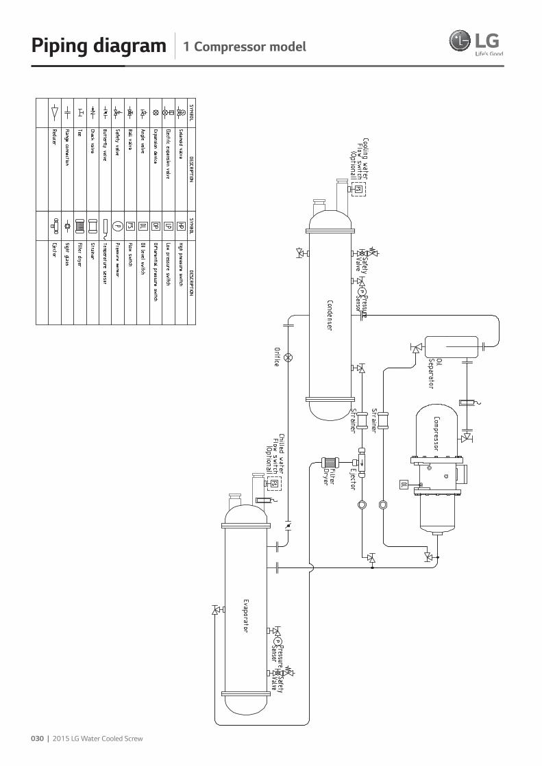
Piping diagram 1 Compressor model
2015 LG HVAC Solution | 031
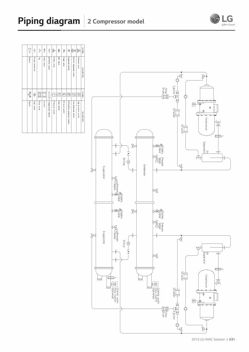
Piping diagram 2 Compressor model
032 | 2015 LG Water Cooled Screw
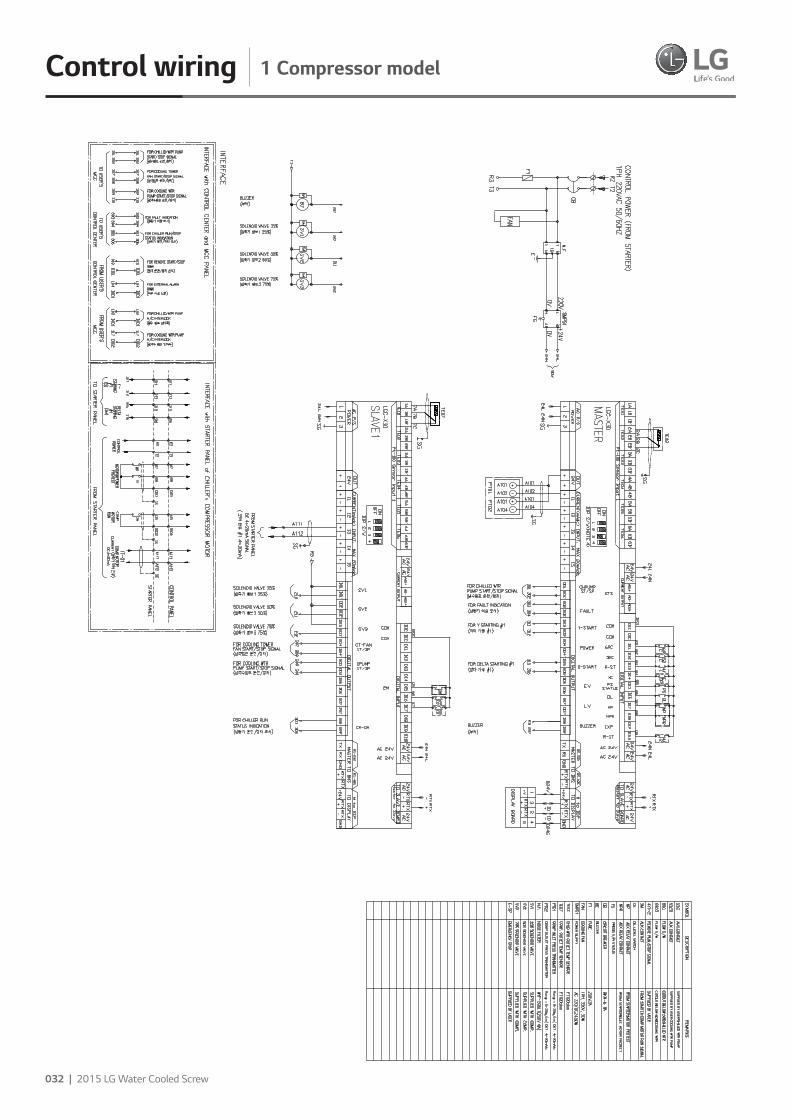
Control wiring 1 Compressor model
2015 LG HVAC Solution | 033
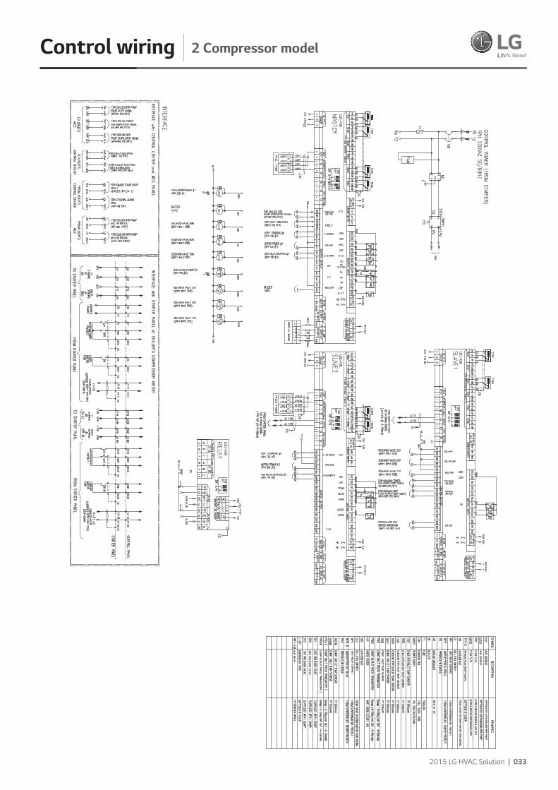
Control wiring 2 Compressor model
034 | 2015 LG Water Cooled Screw
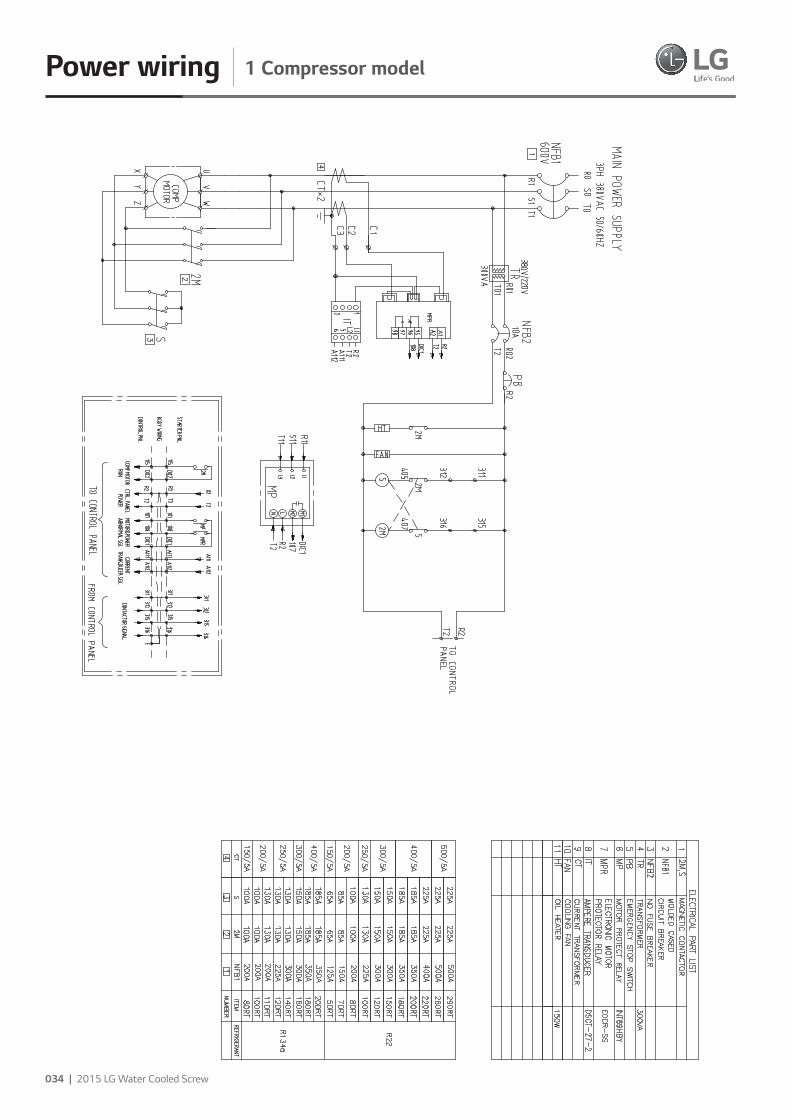
Power wiring 1 Compressor model
2015 LG HVAC Solution | 035
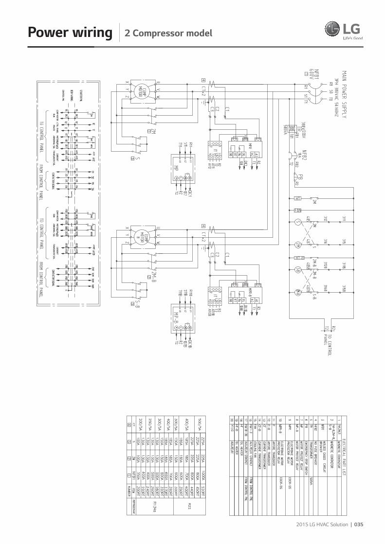
Power wiring 2 Compressor model
Guide specification Contents
Part 1 – General1.01 Scope
1.02 System descriptions
1.03 Quality assurance
1.04 Delivery and handling
Part 2 – Products2.01 General
2.02 Equipment description
2.03 Operating characteristics
2.04 Compressor
2.05 Heat exchanger
2.06 Expansion unit
2.07 Controller
2.08 Characteristics of the controller
2.09 Automatic safety device
2.10 Accessories and options
Part 3 - Execution 3.01 Installation
036 | 2015 LG Water Cooled Screw
2015 LG HVAC Solution | 037
Guide specification
Part 1 – General 1.01 Scope
The requirements of the General Conditions, Supplementary Conditions and Drawings apply to all work herein.
1.02 System descriptionsMicroprocessor controlled water-cooled liquid chiller utilizing screw compressor(s) and electronic expansion valves.
1.03 Quality assurance• AHRI 550/590 - water chilling packages using the vapor compression cycle. • ANSI/ASHRAE 34 - number designation and safety classification
of refrigerants. • ASME Section VIII - boiler and pressure vessel. • GB/T 18430.1 - water chilling (heat pump) packages using the
vapor compression cycle - part 1: water chilling (heat pump) packages for industrial & commercial and similar applications.
• GB25131 - Safety requirements for water chillers (heat pump) using the vapor compression cycle.
• GB150/151 - steel pressure vessels / Tubular heat exchangers. • ANSI/ASHRAE Standard 15 safety code. • Manufactured in an EN ISO 9001 accredited organization.
• The packaged chiller shall be pressure and leak test.• Chiller manufacturer shall have factory trained and supported
service organization local to the chiller installation to provide commissioning and service support throughout the manufacturer’s warranty period.
• Manufacturer shall warrant all equipment and material of its supply against defects in workmanship and material for a period of eighteen (18) months from date of shipment or twelve(12) months from initial start-up, whichever occurs first.
1.04 Delivery and handlingDepending on the condition of the installation site, chiller is shipped as a single unit or as separated unit, and as charged with refrigerant or with nitrogen. If shipped as separated units, contact the authorized LG Electronics dealers or LG Electronics directly. For single unit type, the unit will be delivered to the site as preassembled. Separated unit type will be delivered as 2 or 3 separated main pieces. Confirm and record that it is the correct unit and that it is properly equipped as the submitted packing list. When refrigerant is charged, refrigerant and oil are charged together according to the specification of the chiller unit. It needs special attention to high pressure inside since the saturated refrigerant pressure is decided by the external air temperature. When nitrogen is charged, the unit is charged with 0.5kg/cm2 before shipment from the factory. If the pressure is “0”, please record the condition and check for any leakage, since there is leak possibility.
Unit shall be handled, transported and stored in accordance with manufacturer’s instructions.
Shipping: Unit shall ship in one piece and shall require installer to provide the evaporator and condenser inlet and outlet pipe connections. If providing chiller model that ships in multiple pieces, bid shall include all the material and field labor costs for factory authorized personnel to connect the pieces as well as all interconnecting piping and wiring.
Part 2 – Products2.01 General
The equipment shown on the drawings is based on the model RCWW and MCWW series water cooled liquid chiller as manufactured by the LG Electronics.
2.02 Equipment description
Supply and install and commission as shown on the drawings and schedules complete factory assembled, charged and operationally tested air cooled screw compressor chiller(s) as specified herein. Chiller shall include one or more independent refrigeration circuits, semi hermetic twin screw compressors(s), shell and tube liquid cooler & condenser, Refrigerant R-134a, lubrication system and oil, interconnecting piping and wiring and lockable control center housing safety, operating and capacity controls necessary for the safe automatic operation of the liquid chiller.
2.03 Operating characteristics
- Chiller will be installed in an indoor location and shall be capable of operating in room temperatures between 4.4°C and 15.6°C (40F~60F)
- Provide capacity control system capable of reducing unit capacity to min. 25% of full load.
2.04 Compressor
The semi-hermetic twin screw compressor with precision machined cast iron housing and discharge shutoff valve. Compressor motor is cooled down by refrigerants. The differential pressure type oil lubrication and a filter-integrated type should be used. A compressor integrated type oil separator is used, a check valve should be installed at the discharge side to prevent the backward flowing of the refrigerants. Design working pressure of entire compressor, suction to discharge shall be 30 bar (435 psig) 4-step or stepless control that can control the capacity from 25 % to 100 % using a capacity control slide valve. A discharge/suction shut-off valve is installed.To separate the oil from the refrigerant in which oil is mixed together, the internal oil separator is designed to allow the oil flow into the system to the minimum.
038 | 2015 LG Water Cooled Screw
Guide specification
2.05 Heat exchanger | Falling Film Type |Evaporator shall be of the falling film shell and tube type with removable heads and mechanically cleanable tubes of seamless copper with internally and externally enhanced surface. Distributer located on the top side of inside shell, this makes uniform flow of refrigerant. Through distributer refrigerant flows downward by gravity as a continuous film. Tubes shall be mechanically expanded into multiple grooves in tube sheets. Cooler will incorporate one, two independent refrigerant circuits with a common chilled liquid multi-pass circuit arrangement. Coolers will be factory insulated with 19mm (optional 38) closed cell insulation with all joints vapor sealed and water drain and vent taps in cooler heads.
| Condenser |The shall is manufactured Shell & Tube and shell be constructed and tested in accordance with pressure vessel code for a refrigerant and 10bar(150 psig) water-side pressure.To increase efficiency, sub-cooler is installed for over-cooling of condenser liquid refrigerant.
2.06 Expansion unit Expansion unit consists of butterfly valve and orifice. At 100% load situation, the pressure loss at the orifice is smaller than the refrigerant pressure loss in the condenser, thus the super-cooled refrigerant passes through the orifice. At this stage the maximum amount of refrigerant is flowing into the evaporator. As the load reduces gradually, the circulating amount of refrigerant also reduces and accordingly the refrigerant level in the condenser is getting low. When the amount of liquid refrigerant reduces, the gas amount in the orifice is getting larger, raising the resistance thus controlling the flow rate.
| Refrigerant isolation v/v: Option |Refrigerant isolation valves shall be provided to isolate the referent into the condenser for standard water chilling application.
2.07 Controller | Composition of the control panel |The control panel is composed of a Micom module (a main module, an I/O module, a display and an operation key module), a power supply unit that provides stable power, and a breaker that performs other control jobs or ensures safety, magnetic contact, and a relay for control. The major functions of these modules are as follows.
| Main module |A high-performance microprocessor is installed in the main module and performs the control function optimized to equipment. A high-precision analog/digital converter measures sensor values in real time and displays them on the
screen or applies them for the equipment control. In addition, the RS-485/232C communication port is integrated to support customers’ remote monitoring. Customers can select RS-485 or RS-232C with simple operation. Therefore, It can be responded to the building automation easily.
| Display and operation key module |The display and operation key module is composed of setting values needed for various operation data and equipment operation, a display unit that displays the malfunction information in texts, a key input unit that enables operators to input data or select menus, and a LED lamp display unit. In particular, the convenience for operators is enhanced by allowing them to use keys directly, if keys are used frequently, or select menus. Operation keys are composed of four menu handling keys, three manual control value handling keys, three manual extraction pump handling keys and two run/stop keys to run or stop the equipment operation. If the operation keys are out of order, operators can handle the control valve and the refrigerant value using the text display unit and the menu selection key. In addition, the operation status (temperature, running/stopping of the neighboring device, storage) can be displayed in English, Chinese or Korean for users’ convenience.
| I/O module |The I/O module is composed of a digital input unit which checks the operational state of various switches, and a digital output unit that controls the equipment operation. In addition, a photo coupler is installed at the I/O unit to block noises. All the I/O module data can be sent and received from the main module. Therefore, the malfunction by the EMI, which can occur when the data are transmitted using a regular cable, can be prevented and high availability can be secured.
2.08 Characteristics of the controller | Convenient management of the operation data |The 7.1inch color LCD shows much operation information on a screen. The analog data (e.g., temperature data) can be saved for 300 times by intervals defined by customers. The data can be used to keep operation logs or to perform maintenance work. In addition, the temperature of the chilled water outlet is displayed on a graph so that customers can understand the trend of temperature changes conveniently.
| Safety controller algorithm |The safety parts such as high and low pressure sensor, discharge temperature, current sensor can help product operation without shutdown. This algorithm can be minimized malfunction operations without manual reset.
| Self-diagnosis and malfunction history saving |The microcomputer monitors the equipment state when the equipment is stopped or running, and informs the state
2015 LG HVAC Solution | 039
Guide specification
to operators using text messages, alarm lamps and buzzers. The advice function shows cause of malfunction and checking point and troubleshooting. It can be saved in USB memory with operation and malfunction history.
| Optimized artificial intelligent control algorithm |• Flexible Startup To prevent excessive shocks to the equipment due to any abrupt load at the time of startup, the input power will be supplied gradually.
| Advanced digital PID control |A digital PID control together with its smooth start-up minimizes unnecessary chiller shut-downs by recognizing the optimal PID control point automatically when the chiller is started or the chiller operation mode is changed from manual to automatic, and applying the point to the control formula. Compared with existing analog controls, more stable and accurate temperature control is possible. ※ A digital transmitter to show and monitor the evaporator
pressure/condenser pressure/ differential oil pressure. ※ A digital transmitter to show and monitor the current/voltage.※ PT 100 sensor a chilled water/Cooling water/Oil temperature
PT 100 Sensor installation.
| Scheduled operation function |Customers can conveniently run the equipment using the schedule operation function that allows customers to select Run/Stop and control temperature setting values by weekday or holiday for 11 times per day.
| Customer support function |• Communication function for building automation, remote
surveillance and control The communication function (RS232C/RS485, users can select) is integrated so that the equipment can be connected to customers’ monitoring system with ease. Also, no voltage I/O is provided so that customers can run/stop the equipment or remotely monitor the important operation state using a simple electric wiring. MODBUS is basic specification , BACnet and Modem is optional.
• Help function If a malfunction occurs, the details thereabout will be logged and operators can take measures using the help function.
• Three language support Users can select Korean, Chinese or English languages from the operation menu.
• Pump down function If the operation stops, the pump-down operation will be started automatically and the refrigerants will be gathered at the condenser. Therefore, the equipment can be operated cost-effectively by its improved operation stability and by preventing the liquid suction during the operation.
2.09 Automatic safety device A double protection device that prevents reverse phase, phase loss and overcurrents is installed. Therefore, the compressor can be completely protected against external electric shocks. Chilled water and cooling water safety device • A chilled water pump interlock contact • A cooling water pump interlock contact • A chilled /cooling water flow switch: chilled /cooling water
level – under 50 %. • Chilled water temperature (low): Chilled water out temperature
– under 2.5°C. • Evaporator refrigerant temperature (low) – Refrigerant
temperature – under 2.5°C. ※�A run/stop signal and interlock contact of the chilled water
and cooling water pump is a very important safety device that can prevent freezing and bursting and safety incidents. Therefore, make sure to connect the line in such a way that the chiller, the chilled water pump and the cooling water pump can be linked at the time of operation. ※ In addition, the automatic blocking value should be installed
to prevent the water flow on the cooling water pipe of the chiller if several cooling water pipes are connected in parallel. Then, the automatic blocking valve should be operated in line with the LG control device. To link the automatic blocking valve, the valve should be opened/closed in synchronization with the cooling water pump run/stop signal provided by the control panel.
• For more details, please contact LG service center in advance.
| Chiller protection device |• Evaporator low pressure • Condenser high pressure • Differential oil pressure • Low chilled water flow • Evaporator low temperature • Condenser high temperature • Overcurrent protection • Compressor overheat protection | Motor/Compressor protector |• A reverse phase/phase loss protection relay • A three-phase wire-wound temperature monitoring S/W • A compressor discharge temperature monitoring sensor
2.10 Accessories and options Some accessories and options supersede standard product features. All options are factory-mounted unless otherwise noted.
| Gateway |Provides communication for Building Automation Systems, including BACnet (MS/ TP), Modbus, (Field Commissioned by BAS Manufacturer)
040 | 2015 LG Water Cooled Screw
Guide specification
| General Options |1. Flow Switch: The water flow switch comes with SPDT output
function, 1.6MPa (232 psi) working pressure, -10°C to 120°C (-14°F to 248°F) with 1” NPT connection for upright mounting in horizontal pipe (This flow switch or equivalent must be furnished with each unit). Field mounted.
2. Differential Pressure Switch: 0.2-3 bar (3-45 psig) range with 1/4” NPTE pressure connections. (Field Mounted by Contractor.)
| Vibration Isolation (All Options Field Mounted by Contractor |1” Deflection Spring Isolators: Level adjustable, spring and cage type isolators for mounting under the unit base rails.
| Compressor acoustic enclosure |The compressor acoustic enclosure can be provided as a option to reduce compressor sound levels.
| Single power point connection |For models installed with 2, 3 and 4 compressors, to minimize job site installation cost and time, single point power connection can be provided as an option about the following models. If optional single point power connection is required, terminal block connections will be supplied at the point of incoming single point connection.
| Power factor correction |Provide equipment with power factor correction capacitors as required to maintain a displacement power factor of 95% at all load conditions.
| Double thickness insulation |As a standard, the evaporator shell is insulated with 19mm (3/4”). As a option, it can be insulated with 38mm (1-1/2”).
| NFB (Non-Fused Breaker) power disconnect switch |A non-fused disconnect is available as a factory-installed option for all units with single point power connection units. This option is that power supply is disconnected during service & repair work as well as door interlock.| Suction service isolation valve |Service suction isolation valve is installed with unit for each refrigerant circuit as a standard.| Pressure vessel (options) |The evaporator and condenser can be provided with either ASME or PED pressure vessel codes certification.
Part 3 – Execution 3.01 Installation A. General: rig and install in full accordance with manufacturer’s
requirements, project drawings, and contract documents.B. Location: locate chiller as indicated on drawings, including
cleaning and service maintenance clearance per manufacturer
instructions. Adjust and level chiller on support structure. C. Components: installing contractor shall provide and install all
auxiliary devices and accessories for fully operational chiller. D. Electrical: coordinate electrical requirements and connections
for all power feeds with electrical contractor.E. Controls: coordinate all control requirements and connections
with controls contractor. F. Finish: installing contractor shall paint damaged and abraded
factory finish with touch-up paint matching factory finish.
2015 LG HVAC Solution | 041
Memo
042 | 2015 LG Water Cooled Screw
Memo

2015 LG HVAC Solution | 043
Memo
Distributed by
LG Electronics, Home appliance & Air solution companyTwo IFC, 10 Gukjegeumyung-ro, Yeongdeungpo-gu, Seoul, 150-945, Korea.
www.lg.com www.lgeaircon.com
For continual product development, LG reserves the right to
change specifications or designs without notice.
© 2015 LG Electronics. Printed in Korea. April. 2015
Ver. 201504