Embed Size (px)
Citation preview

Letting November 5, 2021
Notice to Bidders,
Specifications and Proposal
Contract No. 61H15 COOK County Section 10-00055-01-WR (Streamwood) Route FAU 1321 (Il 19) Project HW2M-691 () District 1 Construction Funds
Prepared by F
Checked by
(Printed by authority of the State of Illinois)
105

NOTICE TO BIDDERS
1. TIME AND PLACE OF OPENING BIDS. Electronic bids are to be submitted to the electronic bidding system (iCX-Integrated Contractors Exchange). All bids must be submitted to the iCX system prior to 12:00 p.m. November 5, 2021 at which time the bids will be publicly opened from the iCX SecureVault.
2. DESCRIPTION OF WORK. The proposed improvement is identified and advertised for bids in the
Invitation for Bids as: Contract No. 61H15 COOK County Section 10-00055-01-WR (Streamwood) Project HW2M-691 () Route FAU 1321 (Il 19) District 1 Construction Funds
Reconstruction and widening of roadway, sidewalk replacement, construct multi-use path, roadway lighting and traffic signal upgrade on IL 19 from Winchester DRive to east of Bartlett Road and on Bartlett Road from East Oltendorf Road to south of IL 19 in Streamwood 3. INSTRUCTIONS TO BIDDERS. (a) This Notice, the invitation for bids, proposal and letter of award shall,
together with all other documents in accordance with Article 101.09 of the Standard Specifications for Road and Bridge Construction, become part of the contract. Bidders are cautioned to read and examine carefully all documents, to make all required inspections, and to inquire or seek explanation of the same prior to submission of a bid.
(b) State law, and, if the work is to be paid wholly or in part with Federal-aid funds, Federal law requires the bidder to make various certifications as a part of the proposal and contract. By execution and submission of the proposal, the bidder makes the certification contained therein. A false or fraudulent certification shall, in addition to all other remedies provided by law, be a breach of contract and may result in termination of the contract.
4. AWARD CRITERIA AND REJECTION OF BIDS. This contract will be awarded to the lowest responsive and responsible bidder considering conformity with the terms and conditions established by the Department in the rules, Invitation for Bids and contract documents. The issuance of plans and proposal forms for bidding based upon a prequalification rating shall not be the sole determinant of responsibility. The Department reserves the right to determine responsibility at the time of award, to reject any or all proposals, to re-advertise the proposed improvement, and to waive technicalities.
By Order of the Illinois Department of Transportation
Omer Osman, P.E. Secretary

CONTRACT 61H15
INDEX FOR
SUPPLEMENTAL SPECIFICATIONS AND RECURRING SPECIAL PROVISIONS
Adopted January 1, 2021
This index contains a listing of SUPPLEMENTAL SPECIFICATIONS, frequently used RECURRING SPECIAL PROVISIONS, and LOCAL ROADS AND STREETS RECURRING SPECIAL PROVISIONS. ERRATA Standard Specifications for Road and Bridge Construction (Adopted 4-1-16) (Revised 1-1-21)
SUPPLEMENTAL SPECIFICATIONS
Std. Spec. Sec. Page No. 106 Control of Materials ........................................................................................................................... 1 107 Legal Regulations and Responsibility to Public ................................................................................. 2 109 Measurement and Payment .............................................................................................................. 3 205 Embankment ..................................................................................................................................... 4 403 Bituminous Surface Treatment (Class A-1, A-2, A-3) ........................................................................ 5 404 Micro-Surfacing and Slurry Sealing ................................................................................................... 6 405 Cape Seal .......................................................................................................................................... 17 406 Hot-Mix Asphalt Binder and Surface Course ..................................................................................... 27 420 Portland Cement Concrete Pavement ............................................................................................... 28 424 Portland Cement Concrete Sidewalk ................................................................................................. 30 442 Pavement Patching ........................................................................................................................... 31 502 Excavation for Structures .................................................................................................................. 32 503 Concrete Structures ........................................................................................................................... 35 504 505
Precast Concrete Structures ............................................................................................................. Steel Structures ……………………………………………………………………………………………….
38 40
506 511
Cleaning and Painting New Steel Structures ..................................................................................... Slope Wall ……………………………………………………………………………………………………..
41 42
522 Retaining Walls .................................................................................................................................. 44 542 Pipe Culverts ..................................................................................................................................... 45 586 Sand Backfill for Vaulted Abutments ................................................................................................. 46 602 Catch Basin, Manhole, Inlet, Drainage Structure, and Valve Vault Construction, Adjustment, and
Reconstruction ...................................................................................................................................
48 603 Adjusting Frames and Grates of Drainage and Utility Structures ....................................................... 49 630 Steel Plate Beam Guardrail ............................................................................................................... 50 631 Traffic Barrier Terminals .................................................................................................................... 53 670 Engineer’s Field Office and Laboratory ............................................................................................. 54 701 Work Zone Traffic Control and Protection ......................................................................................... 55 704 Temporary Concrete Barrier .............................................................................................................. 58 780 Pavement Striping ............................................................................................................................. 60 781 783
Raised Reflective Pavement Markers ................................................................................................ Pavement Marking and Marker Removal ………………………………………………………………….
61 62
888 Pedestrian Push-Button ...................................................................................................................... 64 1001 Cement .............................................................................................................................................. 65 1003 Fine Aggregates ................................................................................................................................ 66 1004 Coarse Aggregates ............................................................................................................................ 67 1006 1008
Metals ................................................................................................................................................ Structural Steel Coatings …………………………………………………………………………………….
70 73
1020 Portland Cement Concrete ................................................................................................................ 77 1043 Adjusting Rings .................................................................................................................................. 79 1050 Poured Joint Sealers ......................................................................................................................... 81 1069 Pole and Tower ................................................................................................................................. 83 1077 1083 1095
Post and Foundation ......................................................................................................................... Elastomeric Bearings ………………………………………………………………………………………… Pavement Markings …………………………………………………………………………………………..
84 85 86
1096 Pavement Markers ............................................................................................................................ 87 1101 General Equipment ............................................................................................................................ 88 1102 Hot-Mix Asphalt Equipment ............................................................................................................... 89 1103 Portland Cement Concrete Equipment .............................................................................................. 91 1105 Pavement Marking Equipment .......................................................................................................... 93 1106 Work Zone Traffic Control Devices .................................................................................................... 95

RECURRING SPECIAL PROVISIONS The following RECURRING SPECIAL PROVISIONS indicated by an “X” are applicable to this contract and are included by reference: CHECK SHEET # PAGE NO.
1 X Additional State Requirements for Federal-Aid Construction Contracts ....................................... 97 2 X Subletting of Contracts (Federal-Aid Contracts) ........................................................................... 100 3 X EEO .............................................................................................................................................. 101 4 Specific EEO Responsibilities Non Federal-Aid Contracts ........................................................... 111 5 Required Provisions - State Contracts .......................................................................................... 116 6 Asbestos Bearing Pad Removal ................................................................................................... 122 7 Asbestos Waterproofing Membrane and Asbestos HMA Surface Removal ................................. 123 8 Temporary Stream Crossings and In-Stream Work Pads ............................................................. 124 9 Construction Layout Stakes Except for Bridges ............................................................................ 125
10 X Construction Layout Stakes .......................................................................................................... 128 11 Use of Geotextile Fabric for Railroad Crossing ............................................................................. 131 12 Subsealing of Concrete Pavements .............................................................................................. 133 13 Hot-Mix Asphalt Surface Correction .............................................................................................. 137 14 Pavement and Shoulder Resurfacing ........................................................................................... 139 15 Patching with Hot-Mix Asphalt Overlay Removal .......................................................................... 140 16 Polymer Concrete ......................................................................................................................... 142 17 PVC Pipeliner ............................................................................................................................... 144 18 Bicycle Racks ............................................................................................................................... 145 19 Temporary Portable Bridge Traffic Signals ................................................................................... 147 20 Reserved ...................................................................................................................................... 149 21 Nighttime Inspection of Roadway Lighting .................................................................................... 150 22 English Substitution of Metric Bolts ............................................................................................... 151 23 Calcium Chloride Accelerator for Portland Cement Concrete ....................................................... 152 24 Quality Control of Concrete Mixtures at the Plant ......................................................................... 153 25 X Quality Control/Quality Assurance of Concrete Mixtures .............................................................. 161 26 Digital Terrain Modeling for Earthwork Calculations ..................................................................... 177 27 Reserved ...................................................................................................................................... 179 28 Preventive Maintenance – Bituminous Surface Treatment (A-1) .................................................. 180 29 Reserved ...................................................................................................................................... 186 30 Reserved ...................................................................................................................................... 187 31 Reserved ...................................................................................................................................... 188 32 Temporary Raised Pavement Markers ......................................................................................... 189 33 Restoring Bridge Approach Pavements Using High-Density Foam .............................................. 190 34 Portland Cement Concrete Inlay or Overlay ................................................................................. 193 35 Portland Cement Concrete Partial Depth Hot-Mix Asphalt Patching ............................................ 197 36 37
Longitudinal Joint and Crack Patching .......................................................................................... Concrete Mix Design – Department Provided ………………………………………………………….
200 202
LOCAL ROADS AND STREETS RECURRING SPECIAL PROVISIONS
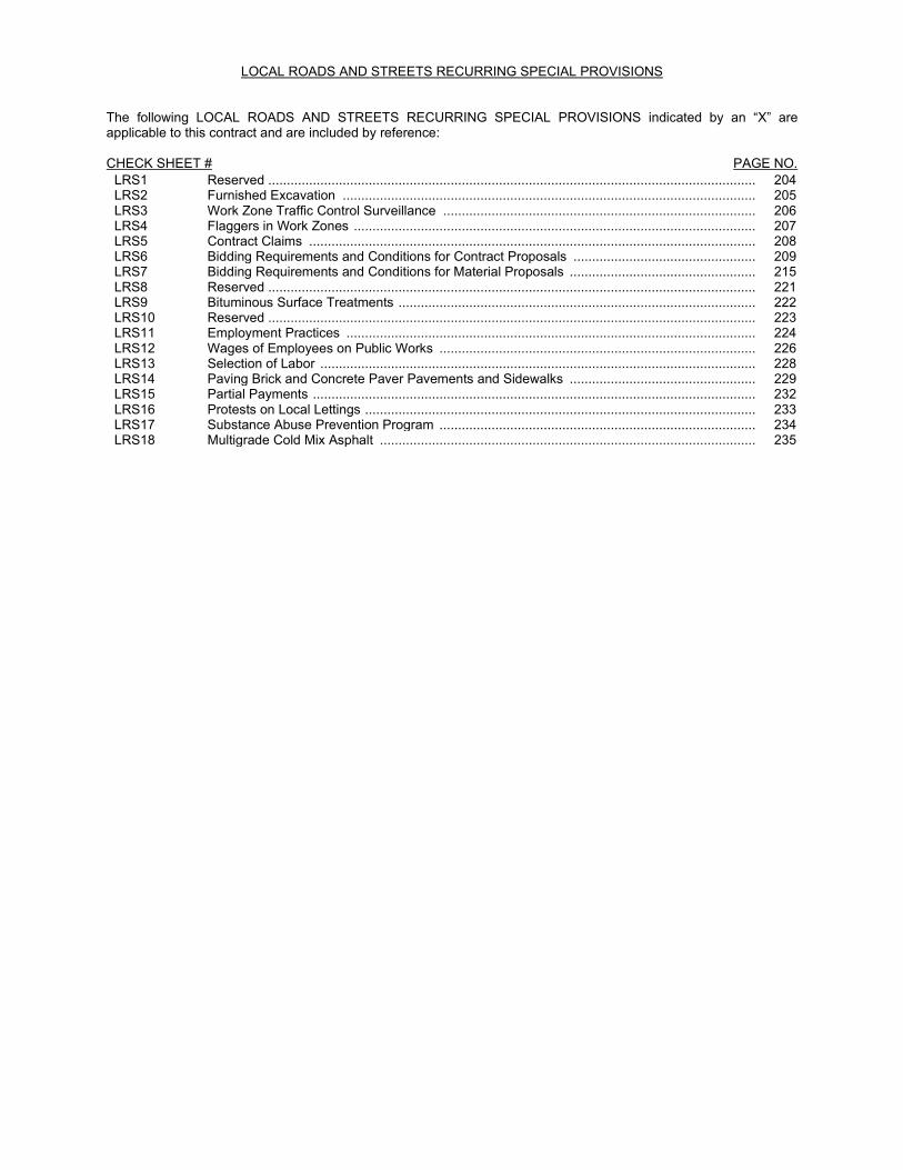
The following LOCAL ROADS AND STREETS RECURRING SPECIAL PROVISIONS indicated by an “X” are applicable to this contract and are included by reference: CHECK SHEET # PAGE NO.
LRS1 Reserved ................................................................................................................................... 204 LRS2 Furnished Excavation ............................................................................................................... 205 LRS3 Work Zone Traffic Control Surveillance .................................................................................... 206 LRS4 Flaggers in Work Zones ............................................................................................................ 207 LRS5 Contract Claims ........................................................................................................................ 208 LRS6 Bidding Requirements and Conditions for Contract Proposals ................................................. 209 LRS7 Bidding Requirements and Conditions for Material Proposals .................................................. 215 LRS8 Reserved ................................................................................................................................... 221 LRS9 Bituminous Surface Treatments ................................................................................................ 222 LRS10 Reserved ................................................................................................................................... 223 LRS11 Employment Practices .............................................................................................................. 224 LRS12 Wages of Employees on Public Works ..................................................................................... 226 LRS13 Selection of Labor ..................................................................................................................... 228 LRS14 Paving Brick and Concrete Paver Pavements and Sidewalks .................................................. 229 LRS15 Partial Payments ....................................................................................................................... 232 LRS16 Protests on Local Lettings ......................................................................................................... 233 LRS17 Substance Abuse Prevention Program ..................................................................................... 234 LRS18 Multigrade Cold Mix Asphalt ..................................................................................................... 235

INDEX OF SPECIAL PROVISIONS
LOCATION OF PROJECT ............................................................................................................................................... 1
DESCRIPTION OF PROJECT ......................................................................................................................................... 1
LIST OF WORK ITEMS NOT PAID FOR SEPARATELY ............................................................................................ 2
MAINTENANCE OF ROADWAYS .................................................................................................................................. 2
STATUS OF UTILITIES (D-1) .......................................................................................................................................... 3
FAILURE TO COMPLETE THE WORK ON TIME ........................................................................................................ 5
AVAILABLE REPORTS .................................................................................................................................................... 5
TRAFFIC CONTROL PLAN ............................................................................................................................................. 6
TRAFFIC CONTROL AND PROTECTION (ARTERIALS) .......................................................................................... 7
TEMPORARY PAVEMENT .............................................................................................................................................. 7
TEMPORARY PAVEMENT (VARIABLE DEPTH) ........................................................................................................ 8
WINTERIZING .................................................................................................................................................................... 8
PUBLIC CONVENIENCE AND SAFETY (D-1) ............................................................................................................. 9
KEEPING ARTERIAL ROADWAYS OPEN TO TRAFFIC (LANE CLOSURES ONLY) .......................................... 9
DETECTABLE WARNINGS .......................................................................................................................................... 10
DETECTABLE WARNINGS(SPECIAL) ....................................................................................................................... 11
TEMPORARY INFORMATION SIGNING ................................................................................................................... 11
AGGREGATE SURFACE COURSE FOR TEMPORARY ACCESS....................................................................... 12
EMBANKMENT II ............................................................................................................................................................ 13
EXPLORATION TRENCH, SPECIAL .......................................................................................................................... 14
STUMP REMOVAL ......................................................................................................................................................... 15
PLANTING WOODY PLANTS ...................................................................................................................................... 15
PLANTING PERENNIAL PLANTS ............................................................................................................................... 23
WEED CONTROL, PRE-EMERGENT GRANULAR HERBICIDE .......................................................................... 28
SUPPLEMENTAL WATERING ..................................................................................................................................... 29
SHREDDED HARDWOOD BARK MULCH ................................................................................................................ 30
LANDSCAPE EDGING .................................................................................................................................................. 31
TOPSOIL FURNISH AND PLACE, SPECIAL ............................................................................................................ 32 FAILURE TO COMPLETE PLANT CARE AND ESTABLISHMENT WORK ON TIME ........................................ 35

COMPOST FURNISH AND PLACE …………………………………………………………………………………..36 COARSE SAND PLACEMENT ………………………………………………………………………………………..38
AGGREGATE SUBGRADE IMPROVEMENT (D-1) .................................................................................................. 38
FRICTION AGGREGATE (D-1) .................................................................................................................................... 40
HOT-MIX ASPHALT BINDER AND SURFACE COURSE (D-1) ............................................................................. 43
HAMBURG WHEEL AND TENSILE STRENGTH RATIO TESTING (D-1) ............................................................ 51
DRAINAGE AND INLET PROTECTION UNDER TRAFFIC (DISTRICT 1) ........................................................... 53
COARSE AGGREGATE FOR BACKFILL, TRENCH BACKFILL AND BEDDING (D-1) ..................................... 54
GROUND TIRE RUBBER (GTR) MODIFIED ASPHALT BINDER (D-1)................................................................ 54
SLIPFORM PAVING (D-1) ............................................................................................................................................ 55
SIGN SHOP DRAWING SUBMITTAL ......................................................................................................................... 56
STORM SEWER (WATER MAIN REQUIREMENTS) ............................................................................................... 56
ADJUSTMENTS AND RECONSTRUCTIONS ........................................................................................................... 56
TELEVISION INSPECTION OF SEWER, SPECIAL ................................................................................................. 57
TEST HOLES .................................................................................................................................................................. 58
MANHOLES, TYPE A, 8’ DIAMETER, TYPE 1, CLOSED LID, RESTRICTOR PLATE ...................................... 58
CONNNECTION TO EXISTING SEWER ................................................................................................................... 58
MANHOLES TO BE ADJUSTED WITH NEW TYPE 1 FRAME, CLOSED LID ..................................................... 59
SANITARY MANHOLES TO BE RECONSTRUCTED WITH NEW TYPE 1 FRAME, CLOSED LID ................. 59
REMOVAL AND DISPOSAL OF REGULATED SUBSTANCES (IRVING PARK ROAD AT BARTLETT ROAD) .............................................................................................................................................................................. 60
WATER DISTRIBUTION SYSTEM .............................................................................................................................. 64
WATER MAIN PIPE ....................................................................................................................................................... 74
CONNECTION TO EXISTING WATER MAIN (NON-PRESSURE) ........................................................................ 75
WATER VALVES ............................................................................................................................................................ 75
WATERMAIN LINE STOP………………………………………………………………………………………………75
WATER SERVICES ....................................................................................................................................................... 75
FIRE HYDRANTS WITH AUXILIARY VALVE AND VALVE BOX ........................................................................... 77
FIRE HYDRANT EXTENSION…………………………………………………………………………………………77
AUXILARY VALVE BOX EXTENTION………………………………………………………………………………..78
VAULTS............................................................................................................................................................................ 78

FIRE HYDRANTS TO BE REMOVED ......................................................................................................................... 79
FILLING VALVE VAULTS ............................................................................................................................................. 79
TRENCH BACKFILL, SPECIAL (WATER MAIN) ...................................................................................................... 79 WATER MAIN DIRECTIONAL BORE (HDD) ............................................................................................................. 80
ABANDON EXISTING WATER MAIN WITH CLSM FILL ......................................................................................... 82
CASING PIPE, OPEN CUT ........................................................................................................................................... 82
TEMPORARY LUMINAIRE, LED, ROADWAY........................................................................................................... 83
GENERAL ELECTRICAL REQUIREMENTS ............................................................................................................. 85
UNDERGROUND RACEWAYS ................................................................................................................................... 99
UNIT DUCT ...................................................................................................................................................................... 99
WIRE AND CABLE ....................................................................................................................................................... 101
LUMINAIRE, LED, SPECIAL ...................................................................................................................................... 102
LIGHT POLE, SPECIAL ............................................................................................................................................... 106
LIGHT POLE FOUNDATION, 24” DIAMETER, OFFSET ....................................................................................... 107
SANITARY SERVICE REPLACEMENT .................................................................................................................... 108
MAST ARM SIGN PANELS ........................................................................................................................................ 109
TRAFFIC SIGNAL GENERAL REQUIREMENTS ................................................................................................... 109
RE-OPTIMIZE TRAFFIC SIGNAL SYSTEM ............................................................................................................ 120
SERVICE INSTALLATION (TRAFFIC SIGNALS) ................................................................................................... 122
GROUNDING OF TRAFFIC SIGNAL SYSTEMS .................................................................................................... 125
COILABLE NON-METALLIC CONDUIT .................................................................................................................... 126
ROD AND CLEAN EXISTING CONDUIT ................................................................................................................. 126
HANDHOLES ................................................................................................................................................................ 127
FIBER OPTIC TRACER CABLE................................................................................................................................. 129
MAINTENANCE OF LIGHTING SYSTEMS .............................................................................................................. 130
MAINTENANCE OF EXISTING LIGHTING SYSTEMS .......................................................................................... 130
MAINTENANCE OF EXISTING TRAFFIC SIGNAL AND FLASHING BEACON INSTALLATION ................... 132
FULL-ACTUATED CONTROLLER AND CABINET ................................................................................................ 135
UNINTERRUPTABLE POWER SUPPLY, SPECIAL............................................................................................... 137

FIBER OPTIC CABLE .................................................................................................................................................. 141
ELECTRIC CABLE ....................................................................................................................................................... 141
EMERGENCY VEHICLE PRIORITY SYSTEM LINE SENSOR CABLE, NO. 20 3/C ........................................ 142 TRAFFIC SIGNAL POST ............................................................................................................................................. 142
MAST ARM ASSEMBLY AND POLE ........................................................................................................................ 142
CONCRETE FOUNDATIONS ..................................................................................................................................... 143
LIGHT EMITTING DIODE (LED) SIGNAL HEAD AND OPTICALLY PROGRAMMED LED SIGNAL HEAD 143
LIGHT EMITTING DIODE (LED) PEDESTRIAN SIGNAL HEAD .......................................................................... 147
TRAFFIC SIGNAL BACKPLATE ................................................................................................................................ 149
DETECTOR LOOP ....................................................................................................................................................... 149
RADAR VEHICLE DETECTION SYSTEM ................................................................................................................ 151
EMERGENCY VEHICLE PRIORITY SYSTEM ........................................................................................................ 152
PEDESTRIAN PUSH-BUTTON .................................................................................................................................. 153
TEMPORARY TRAFFIC SIGNAL INSTALLATION ................................................................................................. 154
TEMPORARY TRAFFIC SIGNAL TIMING................................................................................................................ 161
REMOVE EXISTING TRAFFIC SIGNAL EQUIPMENT .......................................................................................... 161
RAISED REFLECTIVE PAVEMENT MARKER (SPECIAL) ................................................................................... 162
PEDESTRIAN SIGNAL POST .................................................................................................................................... 164
CONCRETE FOUNDATION, PEDESTRIAN POST ................................................................................................ 165
LED INTERNALLY ILLUMINATED STREET NAME SIGN ............................................................................ 166
PORTLAND CEMENT CONCRETE UNDERLAYMENT, 4” ........................................................................... 169
BRICK PAVERS .............................................................................................................................................. 169
IDOT TRAINING PROGRAM ON-THE-JOB TRAINING SPECIAL PROVISION (TPG) ................................... 171
INSURANCE (LR 107) ................................................................................................................................................ 173
STORM WATER POLLUTION PREVENTION PLAN ............................................................................................ 174
LPC 663 .......................................................................................................................................................... 182
WATER MAIN PERMIT............................................................................................................................................... 198

BDE SPECIAL PROVISIONS
The following special provisions indicated by an “X” are applicable to this contract. An * indicates a new or revised special provision for the letting.
File Name
Pg. Special Provision Title Effective Revised
80099 Accessible Pedestrian Signals (APS) April 1, 2003 April 1, 2020 80274 Aggregate Subgrade Improvement April 1, 2012 April 1, 2016 80192 Automated Flagger Assistance Device Jan. 1, 2008 80173 201 X Bituminous Materials Cost Adjustments Nov. 2, 2006 Aug. 1, 2017 80246 Bituminous Surface Treatment with Fog Seal Jan. 1, 2020 80436 203 X Blended Finely Divided Minerals April 1, 2021 80241 Bridge Demolition Debris July 1, 2009 5026I Building Removal-Case I (Non-Friable and Friable Asbestos) Sept. 1, 1990 April 1, 2010 5048I Building Removal-Case II (Non-Friable Asbestos) Sept. 1, 1990 April 1, 2010 5049I Building Removal-Case III (Friable Asbestos) Sept. 1, 1990 April 1, 2010 5053I Building Removal-Case IV (No Asbestos) Sept. 1, 1990 April 1, 2010 80425 Cape Seal Jan. 1, 2020 Jan. 1, 2021 80384 204 X Compensable Delay Costs June 2, 2017 April 1, 2019 80198 Completion Date (via calendar days) April 1, 2008 80199 Completion Date (via calendar days) Plus Working Days April 1, 2008 80293 Concrete Box Culverts with Skews > 30 Degrees and Design Fills ≤
5 Feet April 1, 2012 July 1, 2016
80311 Concrete End Sections for Pipe Culverts Jan. 1, 2013 April 1, 2016 80261 208 X Construction Air Quality – Diesel Retrofit June 1, 2010 Nov. 1, 2014 80387 Contrast Preformed Plastic Pavement Marking Nov. 1, 2017 80434 Corrugated Plastic Pipe (Culvert and Storm Sewer) Jan. 1, 2021 80029 211 X Disadvantaged Business Enterprise Participation Sept. 1, 2000 Mar. 2, 2019 80402 221 X Disposal Fees Nov. 1, 2018 80378 Dowel Bar Inserter Jan. 1, 2017 Jan. 1, 2018 80421 Electric Service Installation Jan. 1, 2020 80415 223 X Emulsified Asphalts Aug. 1, 2019 80423 226 X Engineer’s Field Office Laboratory Jan. 1, 2020 80229 229 X Fuel Cost Adjustment April 1, 2009 Aug. 1, 2017 80417 Geotechnical Fabric for Pipe Underdrains and French Drains Nov. 1, 2019 80420 Geotextile Retaining Walls Nov. 1, 2019 80433 Green Preformed Thermoplastic Pavement Markings Jan. 1, 2021 80304 Grooving for Recessed Pavement Markings Nov. 1, 2012 Nov. 1, 2020 80422 High Tension Cable Median Barrier Jan. 1, 2020 Nov. 1, 2020 80416 Hot-Mix Asphalt – Binder and Surface Course July 2, 2019 Nov. 1, 2019 80398 Hot-Mix Asphalt – Longitudinal Joint Sealant Aug. 1, 2018 Nov. 1, 2019 80406 Hot-Mix Asphalt – Mixture Design Verification and Production
(Modified for I-FIT) Jan. 1, 2019 July 1, 2021
80347 Hot-Mix Asphalt – Pay for Performance Using Percent Within Limits – Jobsite Sampling
Nov. 1, 2014 July 2, 2019
80383 Hot-Mix Asphalt – Quality Control for Performance April 1, 2017 July 2, 2019 80411 Luminaires, LED April 1, 2019 July 1, 2021 80393 232 X Manholes, Valve Vaults, and Flat Slab Tops Jan. 1, 2018 Mar. 1, 2019 80045 Material Transfer Device June 15, 1999 Aug. 1, 2014 80418 Mechanically Stabilized Earth Retaining Walls Nov. 1, 2019 Nov. 1, 2020 80424 Micro-Surfacing and Slurry Sealing Jan. 1, 2020 Jan. 1, 2021 80428 234 X Mobilization April 1, 2020 80412 Obstruction Warning Luminaires, LED Aug. 1, 2019 80430 235 X Portland Cement Concrete – Haul Time July 1, 2020 80359 Portland Cement Concrete Bridge Deck Curing April 1, 2015 Nov. 1, 2019 80431 Portland Cement Concrete Pavement Patching July 1, 2020 80432 236 X Portland Cement Concrete Pavement Placement July 1, 2020

File Name
Pg. Special Provision Title Effective Revised
80300 Preformed Plastic Pavement Marking Type D - Inlaid April 1, 2012 April 1, 2016 3426I Railroad Protective Liability Insurance Dec. 1, 1986 Jan. 1, 2006 80157 Railroad Protective Liability Insurance (5 and 10) Jan. 1, 2006 80306 237 X Reclaimed Asphalt Pavement (RAP) and Reclaimed
Asphalt Shingles (RAS) Nov. 1, 2012 Jan. 2, 2021
80407 247 X Removal and Disposal of Regulated Substances Jan. 1, 2019 Jan. 1, 2020 80419 258 X Silt Fence, Inlet Filters, Ground Stabilization and Riprap Filter
Fabric Nov. 1, 2019 July 1, 2021
80395 Sloped Metal End Section for Pipe Culverts Jan. 1, 2018 80340 264 X Speed Display Trailer April 2, 2014 Jan. 1, 2017 80127 266 X Steel Cost Adjustment April 2, 2014 Aug. 1, 2017 80408 Steel Plate Beam Guardrail Manufacturing Jan. 1, 2019 80413 Structural Timber Aug. 1, 2019 80397 269 X Subcontractor and DBE Payment Reporting April 2, 2018 80391 270 X Subcontractor Mobilization Payments Nov. 2, 2017 April 1, 2019 80437 Submission of Payroll Records April 1, 2021 80435 Surface Testing of Pavements – IRI Jan. 1, 2021 April 1, 2021 80298 271 X Temporary Pavement Marking April 1, 2012 April 1, 2017 80409 274 X Traffic Control Devices – Cones Jan. 1, 2019 80410 Traffic Spotters Jan. 1, 2019 20338 275 X Training Special Provisions Oct. 15, 1975 Sept. 2, 2021 80318 Traversable Pipe Grate for Concrete End Sections Jan. 1, 2013 Jan. 1, 2018 80429 Ultra-Thin Bonded Wearing Course April 1, 2020 * 80439 278 X Vehicle and Equipment Warning Lights Nov. 1, 2021 80288 279 Warm Mix Asphalt Jan. 1, 2012 April 1, 2016 * 80440 Waterproofing Membrane System Nov. 1, 2021 * 80302 281 X Weekly DBE Trucking Reports June 2, 2012 Nov. 1, 2021 80414 Wood Fence Sight Screen Aug. 1, 2019 April 1, 2020 80427 282 X Work Zone Traffic Control Devices Mar. 2, 2020 80071 284 X Working Days Jan. 1, 2002
The following special provisions are in the 2021 Supplemental Specifications and Recurring Special Provisions.
File
Name Special Provision Title New Location(s) Effective Revised
80277 80405 80388 80165 80349
80371
80389
80403
Concrete Mix Design – Department Provided Elastomeric Bearings Equipment Parking and Storage Moisture Cured Urethane Paint System Pavement Marking Blackout Tape Pavement Marking Removal Portland Cement Concrete Traffic Barrier Terminal, Type 1 Special
Check Sheet #37 Article 1083.01 Article 701.11 Article 1008.06 Articles 701.04, 701.19(f), 701.20(j) and 1095.06 Articles 783.02-783.04, 783.06 and 1101.13 Article 1020.04 Table 1 and Note 4 Articles 631.04 and 631.12
Jan. 1, 2012 Jan. 1, 2019 Nov. 1, 2017 Nov. 1, 2006 Nov. 1, 2014
July 1, 2016
Nov. 1, 2017
Nov. 1, 2018
April 1, 2016
Jan. 1, 2010 April 1, 2016
The following special provisions have been deleted from use.
File
Name Special Provision Title Effective Revised
80317 Surface Testing of Hot-Mix Asphalt Overlays
Jan 1, 2013 Aug. 1, 2019

FAU 1321 (Illinois Route 19) Section: 10-00055-01-WR
Village of Streamwood Cook County
Contract 61H15
1
STATE OF ILLINOIS
SPECIAL PROVISIONS
The following Special Provisions supplement the Illinois Department of Transportation’s (IDOT) “Standard Specifications for Road and Bridge Construction,” adopted April 1, 2016, (hereinafter referred to as the “Standard Specifications”); the “Manual on Uniform Traffic Control Devices for Streets and Highways” the “Manual of Test Procedures of Materials”, in effect on the date of invitation for bids; the “Supplemental Specifications and Recurring Special Provisions,” adopted January 1, 2021 as indicated on the Check Sheet included herein, and Standard Specifications for Water and Sewer Main Construction in Illinois latest edition which apply to and govern the construction of FAU 1321 Illinois Route 19, Section No. 10-00055-01-WR, Project No. HW2M(691), Job No. C-91-188-20, Contract No. 61H15, Village of Streamwood, Cook County. In case of conflict with any or parts of said Specifications, the said Special Provisions shall take precedence and shall govern. LOCATION OF PROJECT The project is located on Illinois Route 19 (FAU 1321) from 600 feet west of Bartlett Road to 800 feet east of Bartlett Road and on Bartlett Road from 700 feet south of Illinois Route 19 to 700 feet north of Illinois Route 19. The total gross and net length of the project is 2,800 feet (0.53 miles) within the Village of Streamwood in Cook County. DESCRIPTION OF PROJECT The work consists of roadway reconstruction and widening, Portland cement concrete sidewalk removal and replacement, hot-mix asphalt multi-use path, new combination concrete curb and gutter, storm sewer, water main, roadway lighting, traffic signal, segmental walls, restoration, traffic staging, and all incidental and collateral work necessary to complete the project as shown on the plans and as described herein.
FAU 1321 (Illinois Route 19) Section: 10-00055-01-WR
Village of Streamwood Cook County
Contract 61H15
2
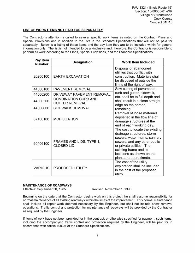
LIST OF WORK ITEMS NOT PAID FOR SEPARATELY The Contractor’s attention is called to several specific work items as noted on the Contract Plans and Special Provisions and in addition to the lists in the Standard Specifications that will not be paid for separately. Below is a listing of these items and the pay item they are to be included within for general information only. The list is not intended to be all-inclusive and, therefore, the Contractor is responsible to perform all work according to the Plans, Special Provisions, and the Standard Specifications.
Pay Item Number
Designation Work Item Included
20200100 EARTH EXCAVATION
Disposal of abandoned utilities that conflict with construction. Materials shall be disposed of outside the limits of the right of way.
44000100 PAVEMENT REMOVAL Saw cutting of pavements, curb and gutter, sidewalk, etc. shall be to full depth and shall result in a clean straight edge on the portion remaining.
44000200 DRIVEWAY PAVEMENT REMOVAL
44000500 COMBINATION CURB AND GUTTER REMOVAL
44000600 SIDEWALK REMOVAL
67100100 MOBILIZATION
Removal of loose materials deposited in the flow line of drainage structures at the end of each working day.
60406100 FRAMES AND LIDS, TYPE 1, CLOSED LID
The cost to locate the existing drainage structures, storm sewers, water mains, sanitary sewers, and any other public or private utilities. The existing frame and lid locations as shown on the plans are approximate.
VARIOUS PROPOSED UTILITY
The cost of the utility exploration shall be included in the cost of the proposed utility.
MAINTENANCE OF ROADWAYS Effective: September 30, 1985 Revised: November 1, 1996 Beginning on the date that the Contractor begins work on this project, he shall assume responsibility for normal maintenance of all existing roadways within the limits of the improvement. This normal maintenance shall include all repair work deemed necessary by the Engineer, but shall not include snow removal operations. Traffic control and protection for maintenance of roadways will be provided by the Contractor as required by the Engineer. If items of work have not been provided for in the contract, or otherwise specified for payment, such items, including the accompanying traffic control and protection required by the Engineer, will be paid for in accordance with Article 109.04 of the Standard Specifications.

FAU 1321 (Illinois Route 19) Section: 10-00055-01-WR
Village of Streamwood Cook County
Contract 61H15
3
STATUS OF UTILITIES (D-1) Effective: June 1, 2016 Revised: January 1, 2020 Utility companies and/or municipal owners located within the construction limits of this project have provided the following information regarding their facilities and the proposed improvements. The tables below contain a description of specific conflicts to be resolved and/or facilities which will require some action on the part of the Department’s contractor to proceed with work. Each table entry includes an identification of the action necessary and, if applicable, the estimated duration required for the resolution. UTILITIES TO BE ADJUSTED Conflicts noted below have been identified by following the suggested staging plan included in the contract. The company has been notified of all conflicts and will be required to obtain the necessary permits to complete their work; in some instances, resolution will be a function of the construction staging. The responsible agency must relocate, or complete new installations as noted below; this work has been deemed necessary to be complete for the Department’s contractor to then work in the stage under which the item has been listed.
Pre-Stage
STAGE / LOCATION
TYPE DESCRIPTION RESPONSIBLE
AGENCY DURATION OF TIME
539+00-553+00 607+50-622+00 PRESTAGE
Electric Aerial lines and
poles
Existing aerial lines and power poles near
right of way to be adjusted and
relocated.
ComEd 100 days.
539+00-545+20 607+50-622+00 PRESTAGE
Cable lines
12” MCD in north parkway and 4” PC in south parkway to be
adjusted and relocated.
AT&T 50 days
539+00-553+00 607+00-622+00 PRESTAGE
Cable lines and poles
Existing aerial lines and power poles near
right of way to be adjusted and
relocated.
Comcast 20 days
539+00-553+00 607+00-622+00 PRESTAGE
Cable lines and poles
Existing aerial lines and power poles near
right of way to be adjusted and
relocated.
W.O.W. 20 days.
539+00-36’RT to 545+00-38’RT 612+50-30’RT-613+50-30’RT- 547+00-40’LT-616+50-45’RT PRESTAGE
Gas main Existing gas main in
roadway and sidewalk. Nicor 100 days.
290 Days total.

FAU 1321 (Illinois Route 19) Section: 10-00055-01-WR
Village of Streamwood Cook County
Contract 61H15
4
The following contact information is what was used during the preparation of the plans as provided by the owner of the facility.
Agency/Company Responsible to Resolve Conflict
Name of contact
Address Phone e-mail address
AT&T
Chris Cass 1000 Commerce Drive Oak Brook, IL 60523
630-573-6414
ComEd
Cassie Evans Tim Tamason Mark Saccomonto
1 Lincoln Center Oakbrook Terrace
708-683-9348, 815-477-5258
[email protected] [email protected] [email protected]
Nicor Gas
Charles Parrott, PE
1844 Ferry Road Naperville, IL 60563
630-388-3319
Streamwood Matt Mann 565 S. Bartlett Road, Streamwood, IL 60107
630-736-3850
Comcast Martha Gieras Nick Mihalka
630-600-6352, 224-229-4513
[email protected] [email protected]
Wide Open West Paul.Flinkow Kevin Rhodes
630-536-3139
[email protected] [email protected]
MWRD Joseph Schuessler
312-751-3236
UTILITIES TO BE WATCHED AND PROTECTED The areas of concern noted below have been identified by following the suggested staging plan included for the contract. The information provided is not a comprehensive list of all remaining utilities, but those which during coordination were identified as ones which might require the Department’s contractor to take into consideration when making the determination of the means and methods that would be required to construct the proposed improvement. In some instances the contractor will be responsible to notify the owner in advance of the work to take place so necessary staffing on the owners part can be secured.
STAGE / LOCATION
TYPE DESCRIPTION OWNER
550+00-LT-553+00LT
Aerial Power Poles
Aerial lines shall be protected from damage by the pavement construction.
ComEd

FAU 1321 (Illinois Route 19) Section: 10-00055-01-WR
Village of Streamwood Cook County
Contract 61H15
5
550+00-LT-553+00 LT
Aerial
Aerial lines shall be protected from damage by pavement construction
Comcast
550+00-LT-553+00LT
Aerial
Aerial lines shall be protected from damage by pavement construction
W.O.W.
The above represents the best information available to the Department and is included for the convenience of the bidder. The days required for conflict resolution should be taken into account in the bid as this information has also been factored into the timeline identified for the project when setting the completion date. The applicable portions of the Standard Specifications for Road and Bridge Construction shall apply. Estimated duration of time provided in the action column for the first conflicts identified will begin on the date of the executed contract regardless of the status of the utility relocations. The responsible agencies will be working toward resolving subsequent conflicts in conjunction with contractor activities in the number of days noted. The estimated relocation dates must be part of the progress schedule submitted by the contractor. A utility kickoff meeting will be scheduled between the Department, the Department’s contractor and the utility companies. The Department’s contractor is responsible for contacting J.U.L.I.E. prior to any and all excavation work.
FAILURE TO COMPLETE THE WORK ON TIME Should the Contractor fail to complete the work on or before the completion dates as specified in the Special Provision for "Working Days", or within such extended time as may have been allowed by the Department, the Contractor shall be liable to the Department in the amount of $2,500,not as a penalty but as liquidated damages, for each calendar day or a portion thereof of overrun in the contract time or such extended time as may have been allowed. In fixing the damages as set out herein, the desire is to establish a certain mode of calculation for the work since the Department's actual loss, in the event of delay, cannot be predetermined, would be difficult of ascertainment, and a matter of argument and unprofitable litigation. This said mode is an equitable rule for measurement of the Department’s actual loss and fairly take into account the loss of use of the roadway if the project is delayed in completion. The Department shall not be required to provide any actual loss in order to recover these liquidated damages provided herein, as said damages are very difficult to ascertain. Furthermore, no provision of this clause shall be construed as a penalty, as such is not the intention of the parties. A calendar day is every day shown on the calendar and starts at 12:00 midnight and ends at the following 12:00 midnight, twenty-four hours later. AVAILABLE REPORTS
☐ No project specific reports were prepared. When applicable, the following checked reports and record information is available for Bidders’ reference upon request:

FAU 1321 (Illinois Route 19) Section: 10-00055-01-WR
Village of Streamwood Cook County
Contract 61H15
6
☐ Record structural plans ☒ Preliminary Site Investigation (PSI)-IDOT
☒ Preliminary Environmental Site Assessment (PESA)-IDOT
☒ Soils/Geotechnical Report
☐ Boring Logs
☐ Pavement Cores ☒ Location Drainage Study (LDS)
☐ Hydraulic Report ☐ Noise Analysis ☐ Other: Those seeking these reports should request access from: HR Green, Inc./Jack Melhuish/Project Manager 420 North Front Street, McHenry, IL 60050 [email protected] 815.759.8342 TRAFFIC CONTROL PLAN Effective: September 30, 1985 Revised: January 1, 2007 Traffic Control shall be according to the applicable sections of the Standard Specifications, the Supplemental Specifications, the "Illinois Manual on Uniform Traffic Control Devices for Streets and Highways", any special details and Highway Standards contained in the plans, and the Special Provisions contained herein. Special attention is called to Article 107.09 of the Standard Specifications and the following Highway Standards, Details, Quality Standard for Work Zone Traffic Control Devices, Recurring Special Provisions and Special Provisions contained herein, relating to traffic control. The Contractor shall contact the District One Bureau of Traffic at least 72 hours in advance of beginning work. Standards 701006-05, 701011-04, 701101-05, 701301-04, 701311-03, 701426-09, 701427-05, 701601-09, 701602-10, 701606-10, 701611-01, 701701-10, 701801-06, 701901-08 Details Traffic Control and Protection for Side Roads, Intersections and Driveways (TC-10)
FAU 1321 (Illinois Route 19) Section: 10-00055-01-WR
Village of Streamwood Cook County
Contract 61H15
7
Raised Reflective Pavement Markers (Snow Plow Resistant) (TC-11) District One Typical Pavement Markings (TC-13) Traffic Control and Protection at Turn Bays (To Remain Open to Traffic) (TC-14) Pavement Marking Letters and Symbols for Traffic Staging (TC-16) Detour Signing for Closing State Highways (TC-21) Arterial Road Information Sign (TC-22) Driveway Entrance Signing (TC-26) Special Provisions Maintenance of Roadways (D-1) Public Convenience and Safety (D-1) Traffic Control and Protection (Arterials) (D-1) Keeping Arterial Roadways Open to Traffic (D-1) Temporary Information Signing (D-1) Temporary Pavement Marking (BDE) Traffic Control Devices-Cones (BDE) Work Zone Traffic Control Devices (BDE) Speed Display Trailer (BDE) TRAFFIC CONTROL AND PROTECTION (ARTERIALS) Effective: February 1, 1996 Revised: March 1, 2011 Specific traffic control plan details and Special Provisions have been prepared for this contract. This work shall include all labor, materials, transportation, handling and incidental work necessary to furnish, install, maintain and remove all traffic control devices required as indicated in the plans and as approved by the Engineer. When traffic is to be directed over a detour route, the Contractor shall furnish, erect, maintain and remove all applicable traffic control devices along the detour route according to the details shown in the plans. Method of Measurement: All traffic control ((except Traffic Control and Protection (Expressways)) and temporary pavement markings) indicated on the traffic control plan details and specified in the Special Provisions will be measured for payment on a lump sum basis. Basis of Payment: All traffic control and protection will be paid for at the contract lump sum price for TRAFFIC CONTROL AND PROTECTION (SPECIAL). Temporary pavement markings will be paid for separately unless shown on a Standard. TEMPORARY PAVEMENT
Effective: March 1, 2003 Revised: April 10, 2008 Description. This work shall consist of constructing a temporary pavement at the locations shown on the plans or as directed by the engineer. The contractor shall use either Portland cement concrete according to Sections 353 and 354 of the Standard Specifications or HMA according to Sections 355, 356, 406 of the Standard Specifications, and other applicable HMA special provisions as contained herein. The HMA mixtures to be used shall be specified in the plans. The thickness of the Temporary Pavement shall be as described in the plans. The contractor shall have the option of constructing either material type if both Portland cement concrete and HMA are shown in the plans.

FAU 1321 (Illinois Route 19) Section: 10-00055-01-WR
Village of Streamwood Cook County
Contract 61H15
8
Articles 355.08 and 406.11 of the Standard Specifications shall not apply. The removal of the Temporary Pavement, if required, shall conform to Section 440 of the Standard Specification.
Method of Measurement. Temporary pavement will be measured in place and the area computed in square yards (square meters). Basis of Payment. This work will be paid for at the contract unit price per square yard (square meter) for TEMPORARY PAVEMENT and TEMPORARY PAVEMENT (INTERSTATE). Removal of temporary pavement will be paid for at the contract unit price per square yard (square meter) for PAVEMENT REMOVAL. TEMPORARY PAVEMENT (VARIABLE DEPTH)
Description. This work shall consist of constructing a temporary pavement at the locations shown on the Plans or as directed by the Engineer. The Contractor shall use hot-mix asphalt (HMA) according to Sections 355, 356, 406 of the Standard Specifications, and other applicable HMA special provisions as contained herein. The HMA mixtures to be used shall be specified in the Plans. The thickness of the Temporary Pavement shall be as described in the Plans or variable in order to meet existing or interim conditions. Articles 355.08 and 406.11 of the Standard Specifications shall not apply. Method of Measurement. TEMPORARY PAVEMENT (VARIABLE DEPTH) will be measured in place at the equivalent weight in tons based upon the area and average depth placed. Basis of Payment. This work will be paid for at the contract unit price per ton for TEMPORARY PAVEMENT (VARIABLE DEPTH). Removal of temporary pavement will be paid for at the contract unit price per square yard for PAVEMENT REMOVAL. WINTERIZING
The Contractor will not be provided additional compensation for maintaining traffic control and protection through winter conditions. Any costs incurred by the Contractor due to winter shutdown will be considered included in the contract unit price for TRAFFIC CONTROL (SPECIAL). The Contractor will not be provided additional compensation for re-startup and de-mobilization / re-mobilization costs over the duration of the contract. The Contractor will not be provided additional compensation for material or labor increases over the duration of the contract, unless the Contractor is awarded time for a delay resulting from any of the categories provided under the “Compensable Delay Costs (BDE)” spec or Article 109.13. Article 108.09 or the Special Provision for “Failure to Complete the Work on Time”, if included in this contract, shall apply to the number of workings days. Portland cement concrete pavement requiring protective coat before traffic opens for the winter season will be included in the contract unit price for PORTLAND CEMENT CONCRETE PAVEMENT 11” JOINTED. If the Contractor chooses to pour concrete during the winter months, anything including but not limited to winter protection, special equipment, additives and protective coat, and any additional material service

FAU 1321 (Illinois Route 19) Section: 10-00055-01-WR
Village of Streamwood Cook County
Contract 61H15
9
charges from supplier required will also be included in the contract unit price for PORTLAND CEMENT CONCRETE PAVEMENT 11” JOINTED. PUBLIC CONVENIENCE AND SAFETY (D-1) Effective: May 1, 2012 Revised: July 15, 2012 Add the following to the end of the fourth paragraph of Article 107.09: “If the holiday is on a Saturday or Sunday, and is legally observed on a Friday or Monday, the length of Holiday Period for Monday or Friday shall apply.” Add the following sentence after the Holiday Period table in the fourth paragraph of Article 107.09: “The Length of Holiday Period for Thanksgiving shall be from 5:00 AM the Wednesday prior to 11:59 PM the Sunday After” Delete the fifth paragraph of Article 107.09 of the Standard Specifications: “On weekends, excluding holidays, roadways with Average Daily Traffic of 25,000 or greater, all lanes shall be open to traffic from 3:00 P.M. Friday to midnight Sunday except where structure construction or major rehabilitation makes it impractical.” KEEPING ARTERIAL ROADWAYS OPEN TO TRAFFIC (LANE CLOSURES ONLY) Effective: January 22, 2003 Revised: August 10, 2017 The Contractor shall provide the necessary traffic control devices to warn the public and to delineate the work zone as required in these Special Provisions, the Standard Specifications, the State Standards, and the District Details. Arterial lane closures shall be in accordance with the Standard Specifications, Highway Standards, District Details, and the direction of the Engineer. The Contractor shall request and gain approval from the Engineer seventy–two (72) hours in advance of all long-term (24 hrs. or longer) lane closures. Arterial lane closures not shown in the staging plans will not be permitted during peak traffic volume hours. Peak traffic volume hours are defined as weekdays (Monday through Friday) from 6:00 AM to 8:30 AM and 4:30 PM to 6:00 PM. Private vehicles shall not be parked in the work zone. Contractor’s equipment and/or vehicles shall not be parked on the shoulders or in the median during non-working hours. The parking of equipment and/or vehicles on State right-of-way will only be permitted at locations approved by the Engineer in accordance with Articles 701.08 and 701.11 of the Standard Specifications. Should the Contractor fail to completely open and keep open all the traffic lanes to traffic in accordance with the limitations specified above, the Contractor shall be liable to the Department for the amount of: One lane or ramp blocked = $ 1,000.00 Two lanes blocked = $ 2,000.00

FAU 1321 (Illinois Route 19) Section: 10-00055-01-WR
Village of Streamwood Cook County
Contract 61H15
10
Not as a penalty but as liquidated and ascertained damages for each and every 15 minute interval or a portion thereof that a lane is blocked outside the allowable time limitations. Such damages may be deducted by the Department from any monies due the Contractor. These damages shall apply during the contract time and during any extensions of the contract time. DETECTABLE WARNINGS This work shall consist of the installation of pre-fabricated panel of truncated domes twenty-four inches (24”) wide and varying in length on concrete sidewalk accessibility ramps at locations as directed by the Engineer along Irving Park Road. Truncated domes shall be in accordance with Article 424.09 of the Standard Specifications. The domes shall parallel the pavement crosswalk in accordance with the latest Highway Standard. The panel shall be Red. The panel shall meet the requirements of ASTM C1028 – Slip Resistance and ASTM G155 – Accelerated Weathering. The Detectable Warning Panel shall be one of the following products: 1. Duratek tile available from Detectile Corporation P.O. Box 3513 Oak Brook, IL 60523 Phone: (630) 734-0277 OR 2. High-Impact Polymer Wet-Set tile available from TufTile, Inc. 1200 Flex Court Lake Zurich, IL 60047 Phone: (888) 960-8897 OR 3. Armor-Tile Replaceable Cast-In Place System available from White Cap Construction Supply 8124 W. 188th Street Mokena, IL 60448 Phone: (815) 464-8828 The product and method used for installing detectable warnings shall come with the following documents which shall be given to the Engineer prior to installation:
(a) Manufacturer’s certification stating the product is fully compliant with ADAAG. (b) Manufacturer’s five year warranty. (c) Manufacturer’s specifications stating the required materials, equipment, installation procedures
and conformance to ASTM C1028 This work will be paid for at the contract unit price per SQUARE FOOT for DETECTABLE WARNINGS.

FAU 1321 (Illinois Route 19) Section: 10-00055-01-WR
Village of Streamwood Cook County
Contract 61H15
11
DETECTABLE WARNINGS(SPECIAL)
Description: Work under this item shall consist of installing cast iron detectable warning tiles as shown on the plans. Work shall be performed according to Section 424 of the Illinois Department of Transportation Standard Specifications for Road and Bridge Construction, except as herein modified. Materials: Detectable warning tiles shall be cast iron, of uniform quality, and free of surface defects. The detectable warnings shall meet requirements of ASTM A 48 Class 30 or better. The dome size and spacing of the cast iron detectable warnings shall meet all requirements of sections R305.1.1 and R305.1.2 of PROWAG. The color of the detectable warning tiles is to be approved by the Engineer unless otherwise specified in the plans and comply with the requirements of section R305.1.3 of PROWAG. If a concrete border is required for installation of the cast iron detectable warnings, it shall comply with section R305.2 of PROWAG. Responsibility of the Contractor: The contractor shall verify all dimensions with the product manufacturer. If using radial units, the contractor shall verify that the radius of the detectable warnings supplied by the manufacturer matches that of the curb radius. The contractor shall ensure that the supplied detectable warnings allow placement of the rows of domes that are aligned parallel with the path of travel. Where detectable warnings are radial, dome orientation is not significant. The contractor shall ensure a maximum vertical transition of ¼” between the edge of the detectable warnings and adjacent concrete. Measurement and Payment: This work will be paid for at the contract unit price per square foot for DETECTABLE WARNINGS (SPECIAL), CAST IRON. TEMPORARY INFORMATION SIGNING Effective: November 13, 1996 Revised: January 29, 2020 Description.

FAU 1321 (Illinois Route 19) Section: 10-00055-01-WR
Village of Streamwood Cook County
Contract 61H15
12
This work shall consist of furnishing, installing, maintaining, relocating for various states of construction and eventually removing temporary informational signs. Included in this item may be ground mount signs, skid mount signs, truss mount signs, bridge mount signs, and overlay sign panels which cover portions of existing signs. Materials. Materials shall be according to the following Articles of Section 1000 - Materials:
Item Article/Section a.) Sign Base (Note 1) 1090 b.) Sign Face (Note 2) 1091 c.) Sign Legends 1091 d.) Sign Supports 1093 e.) Overlay Panels (Note 3) 1090.02
Note 1. The Contractor may use 5/8 inch (16 mm) instead of 3/4 inch (19 mm) thick plywood.
Note 2. The sign face material shall be in accordance with the Department’s Fabrication of Highway Signs Policy.
Note 3. The overlay panels shall be 0.08 inch (2 mm) thick.
GENERAL CONSTRUCTION REQUIREMENTS
Installation. The sign sizes and legend sizes shall be verified by the Contractor prior to fabrication. Signs which are placed along the roadway and/or within the construction zone shall be installed according to the requirements of Article 701.14 and Article 720.04. The signs shall be 7 ft (2.1 m) above the near edge of the pavement and shall be a minimum of 2 ft (600 mm) beyond the edge of the paved shoulder. A minimum of two (2) posts shall be used. The attachment of temporary signs to existing bridges, sign structures or sign panels shall be approved by the Engineer. Any damage to the existing signs and/or structures due to the Contractor's operations shall be repaired or signs replaced, as determined by the Engineer, at the Contractor's expense. Method of Measurement. This work shall be measured for payment in square feet (square meters) edge to edge (horizontally and vertically). All hardware, posts or skids, supports, bases for ground mounted signs, connections, which are required for mounting these signs will be included as part of this pay item. Basis Of Payment. This work shall be paid for at the contract unit price per square foot (square meter) for TEMPORARY INFORMATION SIGNING. AGGREGATE SURFACE COURSE FOR TEMPORARY ACCESS Effective: April 1, 2001 Revised: January 2, 2007 Revise Article 402.10 of the Standard Specifications to read:
“402.10 For Temporary Access. The contractor shall construct and maintain aggregate surface course for temporary access to private entrances, commercial entrances and roads according to Article

FAU 1321 (Illinois Route 19) Section: 10-00055-01-WR
Village of Streamwood Cook County
Contract 61H15
13
402.07 and as directed by the Engineer.
The aggregate surface course shall be constructed to the dimensions and grades specified below, except as modified by the plans or as directed by the Engineer.
(a) Private Entrance. The minimum width shall be 12 ft (3.6 m). The minimum compacted thickness shall be 6 in. (150 mm). The maximum grade shall be eight percent, except as required to match the existing grade.
(a) Commercial Entrance. The minimum width shall be 24 ft (7.2 m). The minimum compacted
thickness shall be 9 in. (230 mm). The maximum grade shall be six percent, except as required to match the existing grade.
(b) Road. The minimum width shall be 24 ft (7.2 m). The minimum compacted thickness shall be 9 in.
(230 mm). The grade and elevation shall be the same as the removed pavement, except as required to meet the grade of any new pavement constructed.
Maintaining the temporary access shall include relocating and/or regrading the aggregate surface
coarse for any operation that may disturb or remove the temporary access. The same type and gradation of material used to construct the temporary access shall be used to maintain it.
When use of the temporary access is discontinued, the aggregate shall be removed and utilized in the permanent construction or disposed of according to Article 202.03.” Add the following to Article 402.12 of the Standard Specifications:
“Aggregate surface course for temporary access will be measured for payment as each for every private entrance, commercial entrance or road constructed for the purpose of temporary access. If a residential drive, commercial entrance, or road is to be constructed under multiple stages, the aggregate needed to construct the second or subsequent stages will not be measured for payment but shall be included in the cost per each of the type specified.” Revise the second paragraph of Article 402.13 of the Standard Specifications to read:
“Aggregate surface course for temporary access will be paid for at the contract unit price per each for TEMPORARY ACCESS (PRIVATE ENTRANCE), TEMPORARY ACCESS (COMMERCIAL ENTRANCE) or TEMPORARY ACCESS (ROAD).
Partial payment of the each amount bid for temporary access, of the type specified, will be paid according to the following schedule:
(a) Upon construction of the temporary access, sixty percent of the contract unit price per each, of the type constructed, will be paid.
(b) Subject to the approval of the Engineer for the adequate maintenance and removal of the temporary
access, the remaining forty percent of the pay item will be paid upon the permanent removal of the temporary access.”
EMBANKMENT II Effective: March 1, 2011 Revised: November 1, 2013
Description. This work shall be according to Section 205 of the Standard Specifications except for the following.

FAU 1321 (Illinois Route 19) Section: 10-00055-01-WR
Village of Streamwood Cook County
Contract 61H15
14
Material. Reclaimed asphalt shall not be used within the ground water table or as a fill if ground water is present. The RAP used shall be according to the current Bureau of Materials and Physical Research Policy Memorandum, “Reclaimed Asphalt Pavement (RAP) for Aggregate Applications”. Gradation deleterious count shall not exceed 10% of total RAP and 5% of other by total weight. CONSTRUCTION REQUIREMENTS Samples. Embankment material shall be sampled and tested before use. The contractor shall identify embankment sources, and provide equipment as the Engineer requires, for the collection of samples from those sources. Samples will be furnished to the Geotechnical Engineer a minimum of three weeks prior to use in order that laboratory tests for compaction can be performed. Embankment material placement cannot begin until tests are completed. Placing Material. In addition to Article 202.03, broken concrete, reclaimed asphalt with no expansive aggregate, or uncontaminated dirt and sand generated from construction or demolition activities shall be placed in 6 inches (150 mm) lifts and disked with the underlying lift until a uniform homogenous material is formed. This process also applies to the overlaying lifts. The disk must have a minimum blade diameter of 24 inches (600 mm). When embankments are to be constructed on hillsides or existing slopes that are steeper than 3H:1V, steps shall be keyed into the existing slope by stepping and benching as shown in the plans or as directed by the Engineer. Compaction. Soils classification for moisture content control will be determined by the Soils Inspector using visual field examination techniques and the IDH Textural Classification Chart. When tested for density in place each lift shall have a maximum moisture content as follows.
a) A maximum of 110 percent of the optimum moisture for all forms of clay soils. b) A maximum of 105 percent of the optimum moisture for all forms of clay loam soils.
Stability. The requirement for embankment stability in article 205.04 will be measured with a Dynamic Cone Penetrometer (DCP) according to the test method in the IDOT Geotechnical Manual. The penetration rate must be equal or less than 1.5 inches (38 mm) per blow. Basis of Payment. This work will not be paid separately but will be considered as included in the various items of excavation. EXPLORATION TRENCH, SPECIAL Description. This work shall be in accordance with Section 213 of the Standard Specifications insofar as applicable and noted herein. Revise Article 213.01 to read:
“This work shall consist of excavating a trench at locations as directed by the Engineer for the purpose of locating existing sewer lines, water mains, sanitary sewers and other utilities within or adjacent to the proposed project limits.” Revise the second paragraph of Article 213.02 to read:
“The trench shall be deep enough to expose the sewer lines, water mains, sanitary sewers or other utilities. The width of the trench shall be sufficient to allow proper investigation to determine if the existing

FAU 1321 (Illinois Route 19) Section: 10-00055-01-WR
Village of Streamwood Cook County
Contract 61H15
15
facility needs to be adjusted. The Contractor shall familiarize himself with the locations of all underground utilities of facilities as outlined in applicable Articles 105 of the Standard Specifications and shall save such facilities from damage.” Revise the fourth paragraph of Article 213.02 to read: “The exploration trench shall be backfilled with trench backfill meeting the requirements of the Standard Specifications, the cost of which shall be included in the item EXPLORATION TRENCH, SPECIAL.” Method of Measurement. This work shall be measured in place and measured per lineal FOOT. Payment shall be based on actual length of trench explored without change in unit price because of adjustment in plan quantities due to field conditions. An estimated length of EXPLORATION TRENCH, SPECIAL has been shown in the Summary of Quantities to establish a unit price, and payment shall be based on actual length of trench explored without change in unit price because of adjustment in plan quantities. This work shall be measured in accordance with Article 213.03. Basis of Payment. This work will be paid for at the contract unit price per FOOT for EXPLORATION TRENCH, SPECIAL and no extra compensation will be allowed for any delays, inconvenience or damage sustained by the Contractor in performing this work. This price shall include excavation, backfill, and disposal of excess material. STUMP REMOVAL
Description. This work shall consist of the cutting, grubbing, removal, and disposal of stumps, as hereinafter defined in accordance with the applicable portions of Section 201of the Standard Specifications, and as specified herein. Definitions. Tree stump – The remaining portion of a tree (as defined in Article 201.02) that has been cut off at or near ground level and the remaining portion of a tree (as defined in Article 201.02) where a substantial portion of the tree trunk remains but almost all of the tree limbs have been removed during utility relocation construction. A multiple-stem tree stump that forks below the 4.5 ft point of measurement will be considered a cluster of individual stumps. A multiple-stem tree stump that forks at or above the 4.5 ft point of measurement will be considered a single tree stump. Tree stumps will not be considered as trees for purposes of measurement and removal. Tree stumps removed during the performance of the work for tree removal will not be measured and paid for separately. Method of Measurement. This work will be measured for payment per unit of diameter where one unit is equal to 1 in. The diameter will be measured at a point 4.5 ft above the highest ground level at the base of the tree stump or at the elevation of cut off, whichever is lower, and will be determined by dividing the measured circumference of the tree stump by 3.1416. Basis of Payment. This work will be paid for at the contract unit price per unit diameter for STUMP REMOVAL ONLY PLANTING WOODY PLANTS
This work shall consist of planting woody plants as specified in Section 253 of the Standard

FAU 1321 (Illinois Route 19) Section: 10-00055-01-WR
Village of Streamwood Cook County
Contract 61H15
16
Specifications with the following revisions: Delete Article 253.03 Planting Time and substitute the following:
Spring Planting. This work shall be performed between March 15th and May 31st except that evergreen planting shall be performed between March 15th and April 30th in the northern zone. Add the following to Article 253.03 (a) (2) and (b):
All plants shall be obtained from Illinois Nurserymen’s Association or appropriate state chapter nurseries. All trees and shrubs shall be dug prior to leafing out (bud break) in the spring or when plants have gone dormant in the fall, except for the following species which are only to be dug prior to leafing out in the spring:
• Maple (Acer spp.)
• Buckeye (Aesculus spp.)
• Serviceberry (Amelanchier spp.)
• Birch (Betulus spp.)
• American Hornbeam (Carpinus caroliana)
• Hickory (Carya spp.)
• Hackberry (Celtis occidentalis)
• Eastern Redbud (Cercis canandensis)
• Hawthorn (Crataegus spp.)
• Walnut (Juglans spp.)
• Tuliptree (Liriodendron spp.)
• Crabapple (Malus spp.)
• Black Tupelo (Nyssa sylvatica)
• American Hophornbeam (Ostraya virginiana)
• Oak (Quercus spp.)
• Sassafras (Sassafras albidum)
• Baldcypress (Taxodium distichum)
• American Linden (Tilia americana) Fall Planting. This work shall be performed between October 1 and November 30 except that evergreen planting shall be performed between August 15 and October 15. Planting dates are dependent on species of plant material and weather. Planting might begin or end prior or after above dates as approved by the Engineer. Do not plant when soil is muddy or during frost. Add the following to Article 253.05 Transportation:
Cover plants during transport with a 70% shade mesh heavy duty tarp to prevent desiccation. Plant material transported without cover shall be automatically rejected. During loading and

FAU 1321 (Illinois Route 19) Section: 10-00055-01-WR
Village of Streamwood Cook County
Contract 61H15
17
unloading, plants shall be handled such that stems are not stressed, scraped or broken and that root balls are kept intact. Delete the third sentence of Article 253.07 and substitute the following:
Trees must be installed first to establish proper layout and to avoid damage to other plantings such as shrubs and perennials. The Contractor shall be responsible for all plant layout. The layout must be performed by qualified personnel. The planting locations must be laid out as shown in the landscape plan. This will require the use of an engineer’s scale to determine some dimensions. Tree locations within each planting area shall be marked with a different color stake/flag and labeled to denote the different tree species. Shrub beds limits must be painted. All utilities shall have been marked prior to contacting the Roadside Development Unit. The Engineer will contact the Roadside Development Unit at (847) 705-4171 to approve the layout prior to installation. Allow a minimum of seven (7) working days prior to installation for approval. Delete the first paragraph to Article 253.08 Excavation of Plant Holes and substitute with
the following:
Protect structures, utilities, sidewalks, bicycle paths, knee walls, fences, pavements, utility boxes, other facilities, lawns and existing plants from damage caused by planting operations. Excavation of the planting hole may be performed by hand, machine excavator, or auger. The excavated material shall not be stockpiled on turf, in ditches, or used to create enormous water saucer berms around newly installed trees or shrubs. Remove all excess excavated subsoil from the site and dispose as specified in Article 202.03. Delete the second sentence of Article 253.08 Excavation of Plant Holes (a) and the third
paragraph of Article 253.08(b) and substitute with the following:
Excavation of planting hole width. Planting holes for trees, shrubs, and vines shall be three times the diameter of the root mass and with 45-degree sides sloping down to the base of the root mass to encourage rapid root growth. Roots can become deformed by the edge of the hole if the hole is too small and will hinder root growth. Planting holes dug with an auger shall have the sides cut down with a shovel to eliminate the glazed, smooth sides and create sloping sides. Excavation of planting hole depth. The root flare shall be visible at the top of the root mass. If the trunk flare is not visible, carefully remove soil from around the trunk until the root flare is visible without damaging the roots. Remove excess soil until the top of the root mass exposes the root collar.

FAU 1321 (Illinois Route 19) Section: 10-00055-01-WR
Village of Streamwood Cook County
Contract 61H15
18
The root flare shall always be slightly above the surface of the surrounding soil. The depth of the hole shall be equal to the depth of the root mass minus 2” allowing the tree or shrub to sit 2” higher than the surrounding soil surface for trees. For stability, the root mass shall sit on existing undisturbed soil. If the hole was inadvertently dug too deep, backfill and recompact the soil to the correct depth.
Excavation of planting hole on slopes. Excavate away the slope above the planting hole to create a flattened area uphill of the planting hole to prevent the uphill roots from being buried too deep. Place the excess soil on the downslope of the planting hole to extend the planting shelf to ensure roots on the downhill side of the tree remain buried. The planting hole shall be three times the diameter of the root mass and saucer shaped. The hole may be a bit elongated to fit the contour of the slope as opposed to the typical round hole on flat ground. Add backfill to create a small berm on the downhill portion of the planting shelf to trap water and encourage movement into the soil to increase water filtration around the tree. Smooth out the slope above the plant where you have cut into the soil so the old slope and the new slope transition together smoothly.
Add the following to Article 253.08 Excavation of Plant Holes (b):
When planting shrubs in shrub beds as shown on the plans or as directed by the Engineer, spade a planting bed edge at approximately a 45-degree angle and to a depth of approximately 3-inches around the perimeter of the shrub bed prior to placement of the mulch. Remove any debris created in the spade edging process and dispose of as specified in Article 202.03.
Delete Article 253.09 (b) Pruning and substitute with the following:
Deciduous Shrubs. Shrubs shall be pruned to remove dead, conflicting, or broken branches and shall preserve the natural form of the shrub. Delete the third and fourth paragraphs of Article 253.10 Planting Procedures and Article
253.10 (a) and substitute the following:
Approved watering equipment shall be at the site of the work and in operational condition PRIOR TO STARTING the planting operation and DURING all planting operations OR PLANTING WILL NOT BE ALLOWED. All plants shall be placed in a plumb position and avoid the appearance of leaning. Confirm the tree is straight from two directions prior to backfilling.
Before the plant is placed in the hole, any paper or cardboard trunk wrap shall be removed. Check that the trunk is not damaged. Any soil covering the tree’s root flare shall be removed to expose the root crown prior to planting. Check the depth of the root ball in the planting hole. With the root flare exposed, the depth of
FAU 1321 (Illinois Route 19) Section: 10-00055-01-WR
Village of Streamwood Cook County
Contract 61H15
19
the hole shall be equal to the depth of the root mass minus 2” allowing the tree or shrub to sit 2” higher than the surrounding soil surface for trees. The root flare shall always be slightly above the surface of the surrounding soil. For stability, the root ball shall sit on existing undisturbed soil. If the hole was inadvertently dug too deep, backfill and recompact the soil to the correct depth. After the plant is place in the hole, all cords and burlap shall be removed from the trunk. Remove the wire basket from the top three quarters (3/4) of the root ball. The remaining burlap shall be loosened and scored to provide the root system quick contact with the soil. All ropes or twine shall be removed from the root ball and tree trunk. All materials shall be disposed of properly. The plant hole shall be backfilled with the same soil that was removed from the hole. Clay soil clumps shall be broken up as much as possible. Where rocks, gravel, heavy clay or other debris are encountered, clean top soil shall be used. Do not backfill excavation with subsoil. The hole shall be 1/3 filled with soil and firmly packed to assure the plant remains in plumb, then saturated with water. After the water has soaked in, complete the remaining backfill in 8” lifts, tamping the topsoil to eliminate voids, and then the hole shall be saturated again. Maintain plumb during backfilling. Backfill to the edge of the root mass and do not place any soil on top of the root mass. Visible root flare shall be left exposed, uncovered by the addition of soil. Add the following to Article 253.10 (b):
After removal of the container, inspect the root system for circling, matted or crowded roots at the container sides and bottom. Using a sharp knife or hand pruners, prune, cut, and loosen any parts of the root system requiring corrective action. Delete the first sentence of Article 253.10(e) and substitute with the following:
Water Saucer. All plants placed individually and not specified to be bedded with other plants, shall have a water saucer constructed of soil by mounding up the soil 4-inches high x 8-inches wide outside the edge of the planting hole. Delete Article 253.11 and substitute the following: Individual trees, shrubs, shrub beds, and vines shall be mulched within 48 hours after being planted. No weed barrier fabric will be required for tree and shrub plantings. Pre-emergent herbicide will be used instead of weed barrier fabric. The pre-emergent herbicide shall be applied prior to mulching. See specification for Weed Control, Pre-Emergent Granular Herbicide. The mulch shall consist of wood chips or shredded tree bark not to exceed two (2) inches in its largest dimension, free of foreign matter, sticks, stones, and clods. Mulch shall be aged in stockpiles for a minimum of four (4) months where interior temperatures reach a minimum of 140-degrees. The mulch shall be free from inorganic materials, contaminants, fuels, invasive
FAU 1321 (Illinois Route 19) Section: 10-00055-01-WR
Village of Streamwood Cook County
Contract 61H15
20
weed seeds, disease, harmful insects such as emerald ash borer or any other type of material detrimental to plant growth. A sample must be supplied to the Roadside Development Unit for approval prior to performing any work. Allow a minimum of seven (7) working days prior to installation for approval. Mulch shall be applied at a depth of 4-inches around all plants within the entire mulched bed area or around each individual tree forming a minimum 6-foot diameter mulch ring around each tree. An excess of 4-inches of mulch is unacceptable and excess shall be removed. Mulch shall not be tapered so that no mulch shall be placed within 6-inches of the shrub base or trunk to allow the root flare to be exposed and shall be free of mulch contact. Care shall be taken not to bury leaves, stems, or vines under mulch material. All finished mulch areas shall be left smooth and level to maintain uniform surface and appearance. After the mulch placement, any debris or piles of material shall be immediately removed from the right of way, including raking excess mulch out of turf areas in accordance with Article 202.03. Delete Article 253.12 Wrapping and substitute the following:
Within 48 hours after planting, screen mesh shall be wrapped around the trunk of all deciduous trees with a caliper of 1-inch or greater. Multi-stem or clump form trees, with individual stems having a caliper of 1-inch or greater, shall have each stem wrapped separately. The screen mesh shall be secured to itself with staples or single wire strands tied to the mesh. Trees shall be wrapped at time of planting, before the installation of mulch. The lower edge of the screen wire shall be in continuous contact with the ground and shall extend up to a minimum of 36-inches or to the lowest major branch, whichever is less. Replacement plantings shall not be wrapped. Delete Article 253.13 Bracing and substitute with the following:
Unless otherwise specified by the Engineer, within 48 hours after planting all deciduous and evergreen trees, with the exception of multi-stem or clump form specimens, over 8-feet in height shall require three 6-foot long steel posts equally spaced from each other and adjacent to the outside of the ball. The posts shall be driven vertically to a depth of 18-inches below the bottom of the hole. The anchor plate shall be aligned perpendicular to a line between the tree and the post. The tree shall be firmly attached to each post with a double guy of 14-gauge steel wire. The portion of the wire in contact with the tree shall be encased in a hose of a type and length approved by the Engineer. During the life of the contract, within 72 hours the Contractor shall straighten any tree that deviates from a plumb position. The Contractor shall adjust backfill compaction and install or adjust bracing on the tree as necessary to maintain a plumb position. Replacement trees shall not be braced. Delete the second sentence of the first paragraph of Article 253.14 Period of Establishment
and substitute the following:

FAU 1321 (Illinois Route 19) Section: 10-00055-01-WR
Village of Streamwood Cook County
Contract 61H15
21
This period shall begin in April and end in November of the same year. Delete the first paragraph of Article 253.15 Plant Care and substitute the following:
From planting until final acceptance of planting, the Contractor shall properly care for all plants including watering, weeding, adjusting braces, repairing water saucers, spraying insect infected plants, or other work which is necessary to maintain the health, vigor and satisfactory appearance of the plantings. The Contractor shall provide plant care a minimum of every two weeks, or within three days following notification by the Engineer. Water shall be applied at a reasonable velocity and distance such as to cause no harm to the plant or displacement of mulch or soil. All requirements for plant care shall be considered as included in the cost of the contract.
Delete the first paragraph of Article 253.15 Plant Care (a) and substitute with the
following:
During plant care watering shall be performed at least every two weeks during the months of April through November. The Contractor shall apply a minimum of 35 gallons of water per tree, 25 gallons per large shrub, 15 gallons per small shrub, and 4 gallons per vine. The Engineer may direct the Contractor to adjust the watering rate and frequency depending upon weather conditions. Add the following to Article 253.15 Plant Care (c):
The contractor shall correct any vine growing across the ground plane that should be growing up desired vertical element (noise wall, retaining wall, fence, knee wall, etc.). Work may include but is not limited to carefully weaving vines through fence and/or taping vines to vertical elements. Add the following to Article 253.15 Plant Care (d):
The contractor shall inspect all trees, shrubs, and vines for pests and diseases at least every two weeks during the months of initial planting through final acceptance. Contractor must identify and monitor pest and diseases and determine action required to maintain the good appearance, health and, top performance of all plant material. Contractor shall notify the Engineer with their inspection findings and recommendations within twenty-four hours of findings. The recommendations for action by the Contractor must be reviewed and by the Engineer for approval/rejection. All approved corrective activities will be included in the cost of the contract and shall be performed within 48 hours following notification by the Engineer. Delete Article 253.16 Method of Measurement and substitute with the following:
Trees, shrubs, evergreens, vines, and seedlings will be measured as each individual plant. (a) This work will be measured for initial payment, in place, for plant material found to be in
live and healthy condition by June 1.

FAU 1321 (Illinois Route 19) Section: 10-00055-01-WR
Village of Streamwood Cook County
Contract 61H15
22
(b) This work will be measured for final payment, in place, for plant material found to be in live and healthy condition upon final acceptance by the department.
(c) Pre-emergent Herbicide will be measured for payment as specified in Weed Control, Pre-
emergent Granular Herbicide.
Delete Article 253.17 Basis of Payment and substitute the following:
This work will be paid for at the contract unit price per each for TREES, SHRUBS, EVERGREENS, or VINES, of the species, root type, and plant size specified; and per unit for SEEDLINGS. The unit price shall include the cost of all materials, mulch, equipment, labor, plant care, watering, and disposal required to complete the work as specified herein and to the satisfaction of the Engineer. Payment will be made according to the following schedule. (a) Initial Payment. Upon completion of planting, mulch, wrapping, and bracing 75 percent of the pay item(s) will be paid.
(b) Final Payment. After the successful completion of all required replacement
plantings, clean-up work and receipt of the “Final Acceptance of Landscape Work” memorandum from the Bureau of Maintenance, or upon execution of a third-party bond, the remaining 25 percent of the pay item(s) will be paid.
(c) The placement of Pre-emergent Herbicide shall be paid for at the contract unit price for WEED CONTROL, PRE-EMERGENT GRANULAR HERBICIDE.
REQUIRED INSPECTION OF WOODY PLANT MATERIAL
Delete Article 1081.01(a)(5) and substitute the following: The place of growth for all material, and subsequent inspection, must be located within 200 miles of the project. Delete Article 1081.01(c)(1) and substitute the following: Inspection of plant material will be made at the nursery by the Engineer, or a duly authorized representative of the Department; all plant material must be in the ground of the nursery supplying the material. The Contractor shall provide the Engineer a minimum of 50 calendar days advance notice of the plant material to be inspected. Written certification by the Nursery will be required certifying that the plants are true to their species and/or cultivar specified in the plans. The Department reserves the right to place identification seals on any or all plants selected. No trees shall be delivered without IDOT seal. Plant material not installed within 60 days of initial

FAU 1321 (Illinois Route 19) Section: 10-00055-01-WR
Village of Streamwood Cook County
Contract 61H15
23
inspection will be required to be re-inspected. PLANTING PERENNIAL PLANTS
Delete Article 254.04(a) Planting Time and substitute the following: Bulbs shall be planted between October 15 and November 30. Bulbs shall not be installed prior to trees, shrubs, perennials, and ornamental grasses are planted. Delete Article 254.06 Layout of Planting and substitute the following: When plants are specified to be planted in prepared soil planting beds, the planting bed shall be approved by the Engineer prior to planting. The Contractor shall be responsible for all plant layout. The layout must be performed by qualified personnel. The planting locations must be laid out as shown in the landscape plan. This will require the use of an engineer’s scale to determine some dimensions. Bed limits shall be painted or flagged. Individual plants layout shall be marked prior to installation. The Engineer will contact the Roadside Development Unit at (847) 705-4171 to approve the layout prior to installation. Allow a minimum of three (3) days prior to installation for approval. Add the following to Article 254.07 Planting Procedures: When planting perennials in bed areas shown on the plans or as directed by the Engineer, the following work shall be performed prior to planting:
• Spade a planting bed edge at approximately a 45 degree angle and to a depth of approximately three (3) inches around the perimeter of the perennial bed. Remove any debris created in the spade edging process and dispose of as specified in Article 202.03.
• Do not plant when soil is muddy.
• Trees and shrubs must be installed first to establish proper layout and to
avoid damage to other plantings.
• Perennial plants shall be planted by a hand method approved by the Engineer. Open holes sized to accommodate roots, place plants so it is level with the surrounding soil and backfill with soil, working carefully to avoid damage to roots and to leave no voids. Build up a small water basin of soil around each plant.
• Thoroughly water plant beds within 2 hours of installation. Do not wash
soil onto crowns of plants.
FAU 1321 (Illinois Route 19) Section: 10-00055-01-WR
Village of Streamwood Cook County
Contract 61H15
24
Delete the first sentence of Article 254.08 Mulching and substitute the following: Within 24 hours, the entire perennial plant bed shall be mulched with two (2) inches of fine grade Shredded Hardwood Bark Mulch. Hardwood bark mulch shall be clean, finely shredded mixed-hardwood bark not to exceed two (2) inches in its largest dimension, free of foreign matter, sticks, stones, and clods. All hardwood mulch shall be processed through a hammer mill. Hardwood bark not processed through a hammer mill shall not be accepted. A mulch sample shall be submitted to the Engineer for approval seven (7) days prior to placing. Care shall be taken to place the mulch to form a saucer around each perennial so as not to smother the plants or bury leaves, stems or vines under mulch material. Delete Article 254.09 (b) Period of Establishment and substitute the following: Perennial plants must undergo a 30-day period of establishment. Additional watering shall be performed not less than once a week for four weeks following installation. Any signs of stress exhibited by plant material must be given special consideration in determining water needs. Water immediately if plants begin to wilt, or if top (1) inch to two (2) inches of soil is dry. Water shall be applied at the rate of a minimum of 2 gallons per square foot. Water to ensure that moisture penetrates throughout the root zone, including the surrounding soil, and only as frequently as necessary to maintain healthy growth. Do not over water. Should excess moisture prevail, the Engineer may delete any or all of the additional watering cycles. In severe weather, the Engineer may require additional watering. Water must be applied in such a manner so as not to damage plant material. Water must trickle slowly into soil and completely soak the root zone. An open end hose is unacceptable. Water early in the day and apply water as close to the soil as possible without washing out soil or mulch. Water at the base of the plant to keep as much water as possible off plant leaves in order to minimize fungus problems. Watering of plants in beds shall be applied in such a manner that all plant holes are uniformly saturated without allowing water to flow beyond the periphery of the bed. Thoroughly saturate all areas of the perennial bed, not just individual plants. The plants to be watered and the method of application will be approved by the Engineer. The Contractor will not be relieved in any way from the responsibility for unsatisfactory plants due to the amount of watering. Any loss of newly installed plant material determined by the Engineer to be due to lack of water, is the responsibility of the contractor to replace at no additional cost. Any damage to plant material due to incorrect watering must be corrected or replace at the Contractors expense, to the satisfaction of the Engineer.

FAU 1321 (Illinois Route 19) Section: 10-00055-01-WR
Village of Streamwood Cook County
Contract 61H15
25
Add the following Article 254.09 Period of Establishment: During the period of establishment, weeds and grass growth shall be removed from within the mulched perennial beds. This weeding shall be performed a minimum of once per week or within 48 hours following notification by the Engineer during the 30-day period of establishment. The Contractor will not be relieved in any way from the responsibility for unsatisfactory plants due to the extent of weeding. The weeding may be performed in any manner approved by the Engineer provided the weed and grass growth, including their roots and stems, are removed from the area specified. Mulch disturbed by the weeding operation shall be replaced to its original condition. All debris that results from this operation must be removed from the right-of-way and disposed of at the end of each day in accordance with Article 202.03. Add the following to Article 254.10 Method of Measurement: a) Disposal of weeds, sod and debris (rock, stones, concrete, bottles, plastic bags, etc.) removed from the perennial planting bed as specified in Article 202.03. Add the following to Article 254.11 Basis of Payment: a) Payment for Shredded Mulch shall be included in contract unit price of the perennial plant pay item. b) The unit price shall include the cost of all materials, equipment, labor, plant care, removal, disposal and incidentals required to complete the work as specified herein and to the satisfaction of the Engineer. GENERAL REQUIREMENTS FOR WEED CONTROL SPRAYING Experience
The Contractor shall have previous experience with the use of weed control chemicals. He/she shall have had at least three (3) season’s experience in ecological restoration and the ability to identify and differentiate between targeted weeds and vegetation to remain. The Contractor shall observe and comply with all sections of the Illinois Custom Spray Law, including licensing. Contractor personnel applying herbicides shall have a valid pesticide applicator license issued by the Illinois Department of Agriculture. The licensed pesticide applicator shall attend the preconstruction meeting and submit
his/her current license to the Engineer. The licensed pesticide applicator shall be qualified

FAU 1321 (Illinois Route 19) Section: 10-00055-01-WR
Village of Streamwood Cook County
Contract 61H15
26
at a minimum in Right-of-Way and Aquatics. The licensed applicator shall work on-site
for every work order issued and approved.
Equipment The equipment used shall consist of a vehicle-mounted tank, pump, spray bar and handgun, plus any other accessories needed to complete the specified work. Spraying shall be done through multiple low-pressure flooding or broad jet nozzles mounted on spray bars operated not more than 36” above the ground. If different sizes or types of nozzles are used to make up the spray pattern, the pressure, sizes and capacities shall be adjusted to provide a uniform rate of application for each segment of the spray pattern. Hand spray guns may be used for spraying areas around traffic control devices, lighting standard and similar inaccessible areas. Maximum speed of the spray vehicle during application of chemical shall be ten (10) miles per hour. Pumps used shall have a volume and pressure capacity range sufficient to deliver the mixture at a pressure to provide the required coverage and to keep the spray pattern full and steady without pulsation or excessive pressure as to cause fogging. Maximum pressure for application shall be 15 PSI. Quick acting shut-off valves and spring-loaded ball check valves shall be provided to stop the spray pattern with a minimum of nozzle drip. In areas where the spray vehicle must traverse the right-of-way, a four-wheel drive vehicle with flotation tires will be required to minimize damage to the ground surface. Additional equipment used shall consist of swiping gloves, wicks, wands, hand spray guns and/or backpack sprayers, plus any other accessories needed to complete the specified work as directed by the Engineer. Wick applicators, swiping gloves, or other such devices may be required to ensure herbicides are applied only to target species. If hand spray guns used are attached to spray vehicle, maximum speed of the spray vehicle during application of chemical shall be five (5) miles per hour. In areas where a vehicle is needed to traverse the right-of-way, a four-wheel drive vehicle with flotation tires will be required to minimize damage to the ground surface. Prior to beginning work, the Contractor shall obtain approval from the Engineer of the spraying equipment proposed for completing this work. The proposed equipment shall be in an operational condition and available for inspection by the Engineer at least two (2) weeks prior to the proposed starting time. If requested by the Engineer, the Contractor shall demonstrate the calibration of the equipment. The equipment must provide consistently uniform coverage and keep the spray mixture sufficiently agitated or the work will be suspended until the equipment is repaired or replaced. Spraying Areas This work includes roadsides and other types of right-of-way of various widths and gradients. Spray areas often extend more than thirty (30) feet from the edge of the roadway, requiring both spray bar and hand gun applications.

FAU 1321 (Illinois Route 19) Section: 10-00055-01-WR
Village of Streamwood Cook County
Contract 61H15
27
When the description of work requires weed control of a stated species, such as teasel, the chemical shall be applied only to locations where the stated species is present. When the description of work requires general weed control within a bed or area, such as broadleaf weed control in turf, then the chemical shall be applied to the entire bed or area. Exclusion of Spraying Areas Areas where weed control spraying is inappropriate or detrimental to the environment, desirable planting, or private property shall be excluded from the spray area. Spraying will not be permitted over any drainage swales or waterways, or other areas where the chemical label prohibits application. Spraying within 150 feet of a natural area or site where endangered or threatened species occur. Responsibility for Prevention of Damage to Private Property The Contractor shall, at all times, exercise extreme caution to prevent damage to residential plantings, flower or vegetable gardens, vegetable crops, farm crops, orchard or desirable plants adjacent to the roadside. The Contractor or Department receives a complaint; the Contractor shall contact a complaint within ten (10) days after receiving a claim for damages, either in person or by letter. The Contractor, or his authorized representative, shall make a personal contact with the complainant within twenty (20) days. The Engineer shall also be notified by the Contractor of all claims for damage he received and shall keep the Engineer informed as to the progress in arriving at a settlement for such claims. Communication with the Engineer The Contractor is required to communicate with the Engineer to receive all required approvals in a timely way and to assure that the Engineer can accurately document the work performed. All work orders with herbicide application shall be directly supervised by the Engineer for
quality assurance and for payment purposes. If the Contractor performs work without the
Engineer’s supervision, work will not be paid for.
It shall be the Contractor’s responsibility to assure that all chemical containers are opened and added to the spray mixture in the presence of the Engineer. The Contractor shall obtain approval from the Engineer to proceed with spraying at each location 24 hours prior to the proposed spray operations. The Contractor’s superintendent shall closely coordinate work with the Engineer at all times in accordance with Article 105.06. The superintendent shall attend weekly progress meetings with the Engineer at the Engineer’s office or other mutually agreed upon location. The superintendent

FAU 1321 (Illinois Route 19) Section: 10-00055-01-WR
Village of Streamwood Cook County
Contract 61H15
28
shall communicate with the Engineer in the field during weed control activities to facilitate accurate completion of work while it is occurring. At the request of the Engineer, the Contractor shall provide a cell phone number where the superintendent can be reached during working hours. The Contractor shall notify the Engineer at least twenty-four (24) hours in advance of either discontinuing or resuming operations on all work orders. Pesticide Application Daily Spray Record The Contractor will be required to properly track pesticide applications as required by the ILG87 Permit. Reported data from this form will be collected and complied annually and reported to the IEPA as required. Within 48 hours of the application of pesticides, including but not limited to herbicides, insecticides, algaecides, and fungicides, the Contractor shall complete and return to the Engineer, Operations form “OPER 2720”. OPER 2720 may be found at the following link: http://www.idot.illinois.gov/Assets/uploads/files/IDOT-Forms/OPER/OPER%202720.docx
WEED CONTROL, PRE-EMERGENT GRANULAR HERBICIDE Description: This work shall consist of spreading a pre-emergent granular herbicide in place of weed barrier fabric in areas as shown on the plans or as directed by the Engineer. This item will be used in mulched plant beds and mulch rings. Delete Article 253.11 and substitute the following: Within 48 hours after planting, mulch shall be placed around all plants in the entire mulched bed or saucer area specified to a depth of 4 inches (100 mm). No weed barrier fabric will be required for tree and shrub planting. Pre-emergent Herbicide will be used instead of weed barrier fabric. The Pre-emergent Herbicide shall be applied prior to mulching. Mulch shall not be in contact with the base of woody stems or trunks. Materials: The pre-emergent granular herbicide shall contain the chemicals Trifluralin 2% active ingredient and Isoxaben with 0.5% active ingredient. The herbicide label shall be submitted to the Engineer for approval at least seventy-two (72) hours prior to application. Method: The pre-emergent granular herbicide shall be used in accordance with the manufacturer’s directions on the package. The granules are to be applied prior to mulching. Apply the granular herbicide using a drop or rotary-type designed to apply granular herbicide or insecticides. Calibrate application equipment to use according to manufacturer’s directions. Check frequently to be sure equipment is working properly and distributing granules uniformly. Do not use spreaders that apply material in narrow concentrated bands. Avoid skips or overlaps as poor weed control or crop injury may occur. More uniform application may be achieved by spreading half of the required amount of product over the area and then applying the remaining half in swaths at right angles to the first. Apply the granular herbicide at the rate of 100 lbs/acre (112 kg/ha) or 2.3 lbs/1000 sq. ft. (11.2 kg/1000 sq. meters).

FAU 1321 (Illinois Route 19) Section: 10-00055-01-WR
Village of Streamwood Cook County
Contract 61H15
29
Method of Measurement: Pre-emergent granular herbicide will be measured in place in Pounds (Kilograms) of Pre-emergent Granular Herbicide applied. Areas treated after mulch placement shall not be measured for payment. Basis of Payment: This work will be paid for at the contract unit price per pound (kilogram) of WEED CONTROL, PRE-EMERGENT GRANULAR HERBICIDE which price shall include all materials, equipment, and labor necessary to complete the work as specified. SUPPLEMENTAL WATERING
Scope: This work will include watering turf, trees, shrubs, vines and perennial plants at the rates specified and as directed by the Engineer. Schedule: Watering will only begin after the successful completion of all period of establishment requirements. Water trees every 10 days throughout the growing season (April 1 to November 30). The Engineer may direct the Contractor to adjust the watering rate and frequency depending upon weather conditions. Watering must be completed in a timely manner. Water trees before trees show signs of water stress. When the Engineer directs the Contractor to do supplemental watering, the Contractor must begin the watering operation within 24 hours of notice. A minimum of 10 units of water per day must be applied until the work is complete. Should the Contractor fail to complete the work on a timely basis or within such extended times as may have been allowed by the Department, the Contractor shall be liable to the Department in the amount of $50.00 per tree per day, $25.00 per shrub per day, $15.00 per vine per day, and $15.00 per perennial per day not as penalty but as liquidated damages, for each calendar day or a portion thereof of overrun in the contract time or such extended time as may have been allowed. In fixing the damages as set out herein, the desire is to establish a mode of calculation for the work since the Department’s actual loss, in the event of delay, cannot be predetermined, would be difficult of ascertainment, and a matter of argument and unprofitable litigation. This said mode is an equitable rule for measurement of the Department’s actual loss and fairly takes into account the loss of the trees if the watering is delayed. The Department shall not be required to provide any actual loss in order to recover these liquidated damages provided herein, as said damages are very difficult to ascertain. Furthermore, no provision of this clause shall be construed as a penalty, as such is not the intention of the parties.A calendar day is every day shown on the calendar and starts at 12:00 midnight and ends at the following 12:00 midnight, twenty four hours later. Source of Water: The Contractor shall notify the Engineer of the source of water used and provide written certification that the water does not contain chemicals harmful to plant growth. Rate of Application: The normal rates of application for watering are as follows. The Engineer will adjust these rates as needed depending upon weather conditions. Trees and Large Shrubs: 35 gallons per tree Medium Size Shrubs: 15 gallons per shrub Vines: 3 gallons per vine

FAU 1321 (Illinois Route 19) Section: 10-00055-01-WR
Village of Streamwood Cook County
Contract 61H15
30
Perennial Plants: 10 gallons per square yard Method of Application: A spray nozzle that does not damage small plants must be used when watering perennial plants or turf. Water shall be applied at the base of the plant to keep as much water as possible off plant leaves. An open hose may be used to water trees, shrubs, and vines if mulch and soil are not displaced by watering. Water shall trickle slowly into soil and completely soak the root zone. The Contractor must supply metering equipment as needed to assure the specified application rate of water. Method of Measurement: Supplemental watering will be measured in units of 1000 gallons (3,785 liters) of water applied as directed. Basis of Payment: This work will be paid for at the contract unit price per unit of SUPPLEMENTAL WATERING, measured as specified. Payment will include the cost of all water, equipment and labor needed to complete the work specified herein and to the satisfaction of the Engineer. SHREDDED HARDWOOD BARK MULCH
Description: The work under this item shall consist of furnishing, transporting, and placing shredded hardwood mulch into planting beds or around trees to the depth specified in areas as shown in the plans, as directed by the Engineer or as described herein. Materials: Hardwood bark mulch shall be clean, finely shredded mixed hardwood bark, not to exceed two (2) inches in its largest dimension, free of foreign matter, sticks, stones, and clods. All hardwood bark mulch shall be processed through a hammermill. A mulch sample and request for material inspection must be supplied to the Engineer for approval prior to performing any work 72 hours prior to application. General Requirements: The Contractor shall supply and install shredded hardwood bark mulch to mulch around trees, shrubs and herbaceous plants in landscaped planting beds. Existing trees require a four (4) foot minimum diameter ring around the base of the tree. Annual areas shall be mulched with pine bark fines. The grade, depth, and condition of the area must be approved by the Engineer prior to placement. The Contractor shall remove all litter and plant debris, repair grade by raking and adding planter soil mix or pulverized topsoil as needed prior to mulching. Care shall be taken not to bury leaves, stems, or vines under mulch material. All finished mulch areas shall be left smooth and level to maintain a uniform surface and appearance. After the mulch placement, any debris or piles of material shall be immediately removed from the right of way, including raking excess mulch out of turf areas. All work areas shall be clean of debris and mulch prior to leaving the site. Submittals: A sample shall be provided prior to performing the work.
Construction Requirements: Place mulch manually around plants as follows:

FAU 1321 (Illinois Route 19) Section: 10-00055-01-WR
Village of Streamwood Cook County
Contract 61H15
31
Annuals: Spread one (1) inch of mulch lightly through annual plantings. Perennials, bulbs, groundcovers, vines, grasses: Spread two (2) inches of mulch around plants. Ensure mulch is away from crowns of plants. Shrubs, including roses: Spread three (3) inches of mulch around shrub. Ensure mulch is away from stems and crown of shrub. Trees, shade and ornamental: Spread three (3) inches of mulch around trees. Do not pile mulch around trunk; ensure root flare is visible. Mechanical or power mulch systems are not acceptable methods of placing shredded hardwood mulch. Method of Measurement: Shredded hardwood bark mulch placed around existing trees will be measured in place and the area computed in square yards. Areas not meeting the depth specified shall not be measured for payment. Basis of Payment: This work will be paid for at the contract unit price per square yard (square meter) for MULCH PLACEMENT, of the thickness specified for existing trees within the landscape improvement limits. Payment shall include all costs for materials, equipment and labor required to complete the work specified herein, including the cost of removing and disposing of any debris. Placement of mulch for all new landscape plantings including new trees, shrubs, vines and perennials included as part of the work in other work items will not be measured separately for payment. Pre-emergent herbicide, if required, shall be paid for separately. LANDSCAPE EDGING
Description: This work shall consist of furnishing and installing aluminum landscape edging where indicated on the plans or as directed by the Engineer. Materials: The materials for this work shall conform to the following requirements: Aluminum Edging shall be 3/16” thick exposed top lip x 8” height x 16 feet long, extruded aluminum. The horizontal base shall have an upward facing angle profile designed to integrate restraint for strait-line and curvilinear application. Finish to be Black Anodized. Construction Methods: Edging shall be installed with 2’ of interlocking overlap between sections. Install per manufactures specifications with top of edging ¼” to ½” above finished grade. Finish grade to be compacted on either side of edging to maintain stability. Anchors shall be placed every 36” minimum with additional anchors provided as necessary to insure edging is securely fixed. Method of Measurement: The work for LANDSCAPE EDGING will be measured for payment in feet, measured along the top of the edging as designated on the plans or as directed by the Engineer. Basis of Payment: Landscape Edging will be paid for at the contract unit price per foot for

FAU 1321 (Illinois Route 19) Section: 10-00055-01-WR
Village of Streamwood Cook County
Contract 61H15
32
LANDSCAPE EDGING, complete in place, including all materials, equipment, tools and labor. TOPSOIL FURNISH AND PLACE, SPECIAL
Work under this item shall be performed in accordance with Section 200 of the Standard Specifications for Road and Bridge Construction except as modified herein. Description: This work shall consist of furnishing, transporting, testing, preparing, and placing a mechanically pulverized and blended planter soil mix at locations shown on the plans or as directed by the Engineer. Materials: Materials shall be according to the following except as modified herein: Article/Section
(a) Fine Aggregate (Note 1)… ............................................................................... 1003.06 (b) Topsoil………………………………………………………………. 1081.05(a)
Note 1.The fine aggregate shall consist of natural sand. General Requirements: The planter soil mix shall consist of two (2) parts pulverized topsoil and one (1) part fine aggregate (sand). The sand, in the amount required to produce an acceptable planter soil mix, shall be mechanically blended during the pulverization process. The planter soil mix shall be stored in stockpiles at the producer’s or supplier’s facility and be protected from erosion, absorption of excess water, and contamination at all times. Delivery to the job site shall only occur after the Engineer has given final approval.
The Contractor shall have the material tested following the guidelines presented below under Soil Testing and, if approved, this stockpile shall be the sole source for planting soil to be delivered to site. The test results and a Request for Inspection form should be sent to the Engineer prior to delivering the material to site. This transmittal must also identify the location of the stockpile. If there are any changes in the source the Contractor shall notify the Engineer immediately. No additional time will be allowed for the completion of this project in order to substitute, test, and approve a new source of planting soil. Topsoil shall be capable of supporting and germinating vegetation. Soil Testing: Test report from a qualified laboratory verifying compliance with specifications and suitability of topsoil for use as a growth material. Test report shall indicate mechanical analysis (content by percent of clay, silt, fine gravel and sand) and chemical analysis, including pH, cation exchange capacity (CEC), organic matter, phosphorous, total and available potassium, essential nutrients, trace elements, and any harmful residual chemicals. Provide Testing Laboratory’s recommendations for amending and fertilizing the soil, as well as any toxicity comments. If soil test results do not meet the above requirements, provide test results for alternate soils. A sample of the topsoil proposed for this work shall be furnished a minimum of ten (10) days before delivery of topsoil to the job site. The sample submitted shall be in a sealed container, approximately one quart in size and appropriately labeled. The container shall be completely filled with uncompacted topsoil.

FAU 1321 (Illinois Route 19) Section: 10-00055-01-WR
Village of Streamwood Cook County
Contract 61H15
33
Mechanical and chemical analyses shall be performed on the planter soil mix sample and the results shall fall within the stated limits shown below.Mechanical Analyses (Note 1)
Particle Size Analysis (AASHTO T88) Minimum Maximum Clay content (< 0.002 mm) 0 % 28 % Silt content (0.002 to 0.05 mm) 45 % 77 % Sand content (0.05 to 2 mm) 25 % 33 % Gravel content (>2 mm) 0 % 5 %
Organic Content (AASHTO T194) 5 % 10 %
Chemical Analyses
General Components (Note 2) Minimum Maximum pH value 5.5 7.5 Cation Exchange Capacity (meq/100g) 15 N/A Soluble salt (mmho/cm) 0 1.7 Sodium (ppm) 0 200 Sulfur (ppm) 10 40
Primary Nutrients Phosphorous (ppm)
30
40
Potassium (ppm) 90 240
Secondary Nutrients Magnesium (ppm)
60
1000
Calcium (ppm) 600 5500
Micronutrients (Note 3) Minimum Maximum Zinc (ppm) 1 10 Manganese (ppm) 12 40 Boron (ppm) 1 4 Copper (ppm) 1 6 Iron (ppm) 15 200
Note 1. Mechanical analysis testing on the QA split comparison sample will be granted an additional 10% tolerance on the upper and lower limits for determining approval by the Engineer. Note 2. Any constituents added to the final mixture in an attempt to bring one or more of the General Component ingredients within tolerance will not be allowed and will be cause for the immediate rejection of the planter soil mix material in its entirety. Note 3. Micronutrient testing on the QA split comparison sample will be granted an additional 20% tolerance on the upper and lower limits for determining final approval by the Engineer. Results outside the increased tolerance range will be subject to review and acceptance on a case by case basis as determined by the Engineer. Delivery, Storage and Handling: Protect soil from absorbing excess water and from erosion at all times. Do not store materials unprotected from large rainfall events. Do not allow excess

FAU 1321 (Illinois Route 19) Section: 10-00055-01-WR
Village of Streamwood Cook County
Contract 61H15
34
water to enter site prior. Preparation and Placement:
1. Perform or coordinate final adjustments of any utility structure. Excavation and grading around tree roots, plant materials and buried utilities shall be done by hand. Refer to PROTECTION OF EXISTING TREES specification for required procedures in protected zones. Obtain utility locations prior to excavation.
2. Clean planting areas of all trash and debris before placement of topsoil. Remove and
legally dispose of debris off site in accordance with Article 202.03. Repair to the satisfaction of the Engineer any portion of the geotechnical fabric or drainage layers prior to installation of amended topsoil.
3. After areas required to be landscaped have been brought to required subgrade,
thoroughly till to minimum depth of 6 inches by scarifying, disking, harrowing, or other
approved methods. Remove debris and stones larger than one inch in any dimension
remaining on surface after tillage. Immediately prior to placing topsoil, scarify subgrade
to a two-inch depth for bonding of topsoil with subsoil.
4. Spread topsoil evenly to minimum depth of six inches. Do not spread topsoil when
frozen or excessively wet or dry. Correct all irregularities in finished surfaces to eliminate
depressions. Protect finished topsoil areas from damage by vehicular or pedestrian
traffic.
5. Apply fertilizer at rates and analysis determined by laboratory soil test of soils at job site
and topsoil supplied. Apply fertilizer at rate of 3 pounds per 1000 square feet.
Incorporate fertilizer, pH adjuster, and soil conditioners into soil to minimum depth of 6
inches. This may be done as part of the subgrade tillage operation specified above.
6. Install amended topsoil to the following depths: a. Sod, Seed or Turf: 6 inches minimum b. Vine / Perennial Beds: 12 inches minimum c. Shrub Beds: 24 inches minimum d. Tree Pits: 4 inches below bottom of root ball and expanded root balls (when
poor soils are encountered)
7. Place, spread and rough grade specified planting soil to depths specified in all areas to be planted. Place topsoil mix in two level (2) lifts. The first lift shall contain 2/3 of the planter soil depth. After placing each lift, moisten the surface at a rate sufficient to hydraulically settle the soil, as determined by the Engineer. Allow water to thoroughly percolate through the soil before placing the next lift. Allow for settling, and place additional planting soil as necessary. Allow for placement and mixing of compost and sand, as determined by the Engineer, but place enough soil mix to meet finish grades within =/- 0.10 foot of design grades.
8. Rake smooth and finish grade all planted areas to create an even surface free of pockets where water may stand and to an elevation that will allow for planting installation at

FAU 1321 (Illinois Route 19) Section: 10-00055-01-WR
Village of Streamwood Cook County
Contract 61H15
35
finish grades indicated on plans. The removal of excess material or the addition of planting soil may be required prior to landscaping. This shall be considered incidental to planting soil. Grading will be to a tolerance +/- .10 foot of design grades.
9. The surface of the topsoil after spreading and grading shall be free from clods, stones,
sticks and debris, and shall conform to the lines, grades and the minimum thickness shown on the plans. One rolling of the entire surface shall be made.
10. All debris, litter, tire tracks, dirt, and unintended materials shall be removed, swept or
washed off of all landscape, hard median surfaces, and pavement on a daily basis. Topsoil Acceptance:
The Engineer retains the right to visually inspect topsoil on site before placement. The Engineer may ask that material suspected of not meeting specification be removed from the site, until the material can be mechanically tested. The Contractor shall remove all topsoil and install material meeting this specification. The Contractor shall be responsible for all costs incurred to remove deficient material and install acceptable planting soil. No additional time will be provided in the contract to perform remedial work. Method of Measurement: TOPSOIL FURNISH AND PLACE, SPECIAL will be measured in place to the depth specified in cubic yards (cubic meters) and the volume computed by the method of average end areas. Payment will not be based on load tickets. Existing material removed for the placement of new topsoil shall be measured for payment separately. Removal and disposal of unstable and/or unsuitable materials will be paid for at the contract unit price for REMOVAL AND DISPOSAL OF UNSUITABLE MATERIAL. Removal and re-use of existing soil shall be paid for at the contract unit price for EARTH EXCAVATION or TOPSOIL EXCAVATION AND PLACEMENT, SPECIAL. Basis of Payment: This work will be paid for at the contract unit price per cubic yards (cubic meters) for TOPSOIL FURNISH AND PLACE, SPECIAL, of the thickness specified. Payment shall include all costs for materials, testing soils, furnishing, stockpiling, raking, rolling, disking and tilling, transporting of materials, all labor and equipment necessary, disposal and incidentals required to complete the work as specified herein and to the satisfaction of the Engineer. FAILURE TO COMPLETE PLANT CARE AND ESTABLISHMENT WORK ON TIME
Should the Contractor fail to complete the plant care and/or supplemental watering work within the scheduled time frame as specified in the Special Provision for “Planting Woody Plants”, “Planting Perennial Plants”, “Perennial Plant Care”, and “Supplemental Watering“, or within 36 hours notification from the Engineer, or within such extended times as may have been allowed by the Department, the Contractor shall be liable to the Department in the amount of:
• $50.00 per tree/per day
• $40.00 per large shrub/per day
• $35.00 per small shrub/per day

FAU 1321 (Illinois Route 19) Section: 10-00055-01-WR
Village of Streamwood Cook County
Contract 61H15
36
• $20.00 per vine/per day
• $20.00 per perennial/per day
• $20.00 per sq yd sod/per day not as penalty but as liquidated damages, for each calendar day or a portion thereof of overrun in the contract time or such extended time as may have been allowed. In fixing the damages as set out herein, the desire is to establish a mode of calculation for the work since the Department’s actual loss, in the event of delay, cannot be predetermined, would be difficult of ascertainment, and a matter of argument and unprofitable litigation. This said mode is an equitable rule for measurement of the Department’s actual loss and fairly takes into account the loss of the tree(s) if the watering or plant care is delayed. The Department shall not be required to provide any actual loss in order to recover these liquidated damages provided herein, as said damages are very difficult to ascertain. Furthermore, no provision of this clause shall be construed as a penalty, as such is not the intention of the parties. A calendar day is every day shown on the calendar and starts at 12:00 midnight and ends at the following 12:00 midnight, twenty-four hours later. COMPOST FURNISH AND PLACE
This work shall consist of furnishing, transporting, and placing compost to the depth specified in areas as shown in the plans or as directed by the Engineer. Delete Article 211.02 Materials (b) Compost and substitute the following: Compost shall be thoroughly, and aerobically decomposed organic waste produced at an IEPA registered composting facility. The compost supplier shall furnish a certification with each shipment stating that the compost complies with the following requirements:
(1) Particle Size: 98 percent of the compost shall pass through a 3/4 in. (20 mm)
screen. (2) Physical Contaminant: Less than one percent combined glass, metal, and
plastic. (3) Organic Matter/Ash Content: At least 40 percent organic matter; less than 60
percent ash content. (4) Carbon to Nitrogen Ratio: Ranging from 10:1 to 20:1 C:N ratio. (5) pH: Between 6 and 8. (6) Soluble Salts: Electrical conductivity below 10 dS m-1 (mmhos cm-1)

FAU 1321 (Illinois Route 19) Section: 10-00055-01-WR
Village of Streamwood Cook County
Contract 61H15
37
(7) Moisture Content: Between 35 percent and 50 percent by weight. (8) Maturity: The compost shall be resistant to further decomposition and free of
compounds, such as ammonia and organic acids, in concentrations toxic to plant growth.
(9) Residual Seeds and Pathogens: Pathogens and noxious weeds shall be
minimized. A copy of the compost test results complying with IEPA standards for General Use Compost and certification of IEPA registration shall be provided to the Engineer with each shipment of compost.
Compost shall be capable of supporting and germinating vegetation.
Delete the first sentence of the first paragraph of Article 211.04 Placing Topsoil and Compost and substitute the following: Compost shall not be placed until the area to be covered has been shaped, trimmed and finished according to Section 212. Prior to placing compost the contractor shall remove all litter (including plastic bags, bottles, rocks, etc.) and plant debris. Delete the second paragraph of Article 211.04 Placing Topsoil and Compost and substitute the following:
When compost is specified as a soil amendment, it shall be place at the specified depth on top of the topsoil. The Engineer will verify that the proper compost depth has been applied. After verification of proper depth, the Contractor shall completely incorporate the compost by tilling the top 6” of the fairly dry topsoil. Do not till when the topsoil is muddy.
Add the following to Article 211.07 Basis of Payment: Compost Furnish and Place will be measured in place to the depth specified. Add the following to Article 211.08 Basis of Payment:
The work will be paid for at the contract unit price per square yard for COMPOST FURNISH AND PLACE, 2”. Payment shall include all furnishing, stockpiling, transporting, all labor and equipment necessary, disposal and incidentals required to complete the work as specified herein and to the satisfaction of the Engineer.

FAU 1321 (Illinois Route 19) Section: 10-00055-01-WR
Village of Streamwood Cook County
Contract 61H15
38
COARSE SAND PLACEMENT
Description: This work shall consist of furnishing, transporting, spreading, and incorporating Coarse Sand (FA 2) into the soil in areas shown on the plans and as directed by the Engineer. Materials: Materials shall meet the requirements of the following Article of Section 1000 – Materials: Item Article / Section (a) Fine Aggregate……………………………………………1003.04 Method: Coarse Sand shall not be placed until the area designated has been shaped, trimmed, and finished in accordance with Section 212 of the Standard Specifications and any required placement of Topsoil has been completed. Prior to Coarse Sand placement, the area shall be disked or raked to a minimum depth of 4 inches (100 mm) and all debris and loose stones removed. The grades and condition of the area must be approved by the Engineer prior to Coarse Sand placement. The Coarse Sand shall be placed in the planting beds to the depth specified. After the Engineer verifies that the proper Coarse Sand depth has been applied, the Contractor shall completely incorporate the sand into the soil to a minimum depth of 6 inches (150 mm) by raking, disking, or roto tilling to amend the existing topsoil. After the Coarse Sand has been incorporated into the soil, any debris or piles of unincorporated material shall be immediately removed from the right-of-way and the area finished to the lines and grades shown on the plans and approved by the Engineer. Disposal of material shall be done in accordance with Article 202.03. Method of Measurement: Coarse Sand Placement will be measured in square yards (square meters) at the location shown in the plans and as directed by the Engineer prior to incorporation into the soil. Basis of Payment: This work will be paid for at the contract unit price per square yards (square meters) for COARSE SAND PLACEMENT of the thickness specified. Payment shall include all costs for materials, equipment, and labor required to complete the work specified herein. AGGREGATE SUBGRADE IMPROVEMENT (D-1) Effective: February 22, 2012 Revised: April 1, 2016 Add the following Section to the Standard Specifications:
“SECTION 303. AGGREGATE SUBGRADE IMPROVEMENT
303.01 Description. This work shall consist of constructing an aggregate subgrade improvement.
303.02 Materials. Materials shall be according to the following.
Item Article/Section
(a) Coarse Aggregate ................................................................................................................ 1004.07 (b) Reclaimed Asphalt Pavement (RAP) (Notes 1, 2 and 3) .......................................................... 1031

FAU 1321 (Illinois Route 19) Section: 10-00055-01-WR
Village of Streamwood Cook County
Contract 61H15
39
Note 1. Crushed RAP, from either full depth or single lift removal, may be mechanically blended
with aggregate gradation CS 01 but shall not exceed 40 percent by weight of the total product. The top size of the Coarse RAP shall be less than 4 in. (100 mm) and well graded.
Note 2. RAP having 100 percent passing the 1 1/2 in (37.5 mm) sieve and being well graded, may
be used as capping aggregate in the top 3 in. (75 mm) when aggregate gradation CS 01 is used in lower lifts. When RAP is blended with any of the coarse aggregates, the blending shall be done with mechanically calibrated feeders. The final product shall not contain more than 40 percent by weight of RAP.
Note 3. The RAP used for aggregate subgrade improvement shall be according to the current
Bureau of Materials and Physical Research Policy Memorandum, “Reclaimed Asphalt Pavement (RAP) for Aggregate Applications”.
303.03 Equipment. The vibratory machine shall be according to Article 1101.01, or as approved by
the Engineer. The calibration for the mechanical feeders shall have an accuracy of ± 2.0 percent of the actual quantity of material delivered.
303.04 Soil Preparation. The stability of the soil shall be according to the Department’s Subgrade Stability Manual for the aggregate thickness specified.
303.05 Placing Aggregate. The maximum nominal lift thickness of aggregate gradation CS 01 shall be 24 in. (600 mm).
303.06 Capping Aggregate. The top surface of the aggregate subgrade shall consist of a minimum 3 in. (75 mm) of aggregate gradations CA 06 or CA 10. When Reclaimed Asphalt Pavement (RAP) is used, it shall be crushed and screened where 100 percent is passing the 1 1/2 in. (37.5 mm) sieve and being well graded. RAP that has been fractionated to size will not be permitted for use in capping. Capping aggregate will not be required when the aggregate subgrade improvement is used as a cubic yard pay item for undercut applications. When RAP is blended with any of the coarse aggregates, the blending shall be done with mechanically calibrated feeders.
303.07 Compaction. All aggregate lifts shall be compacted to the satisfaction of the Engineer. If the
moisture content of the material is such that compaction cannot be obtained, sufficient water shall be added so that satisfactory compaction can be obtained.
303.08 Finishing and Maintenance of Aggregate Subgrade Improvement. The aggregate
subgrade improvement shall be finished to the lines, grades, and cross sections shown on the plans, or as directed by the Engineer. The aggregate subgrade improvement shall be maintained in a smooth and compacted condition.
303.09 Method of Measurement. This work will be measured for payment according to Article
311.08. 303.10 Basis of Payment. This work will be paid for at the contract unit price per cubic yard (cubic
meter) for AGGREGATE SUBGRADE IMPROVEMENT or at the contract unit price per square yard (square meter) for AGGREGATE SUBGRADE IMPROVEMENT, of the thickness specified.
Add the following to Section 1004 of the Standard Specifications:
“ 1004.07 Coarse Aggregate for Aggregate Subgrade Improvement. The aggregate shall be according to Article 1004.01 and the following.

FAU 1321 (Illinois Route 19) Section: 10-00055-01-WR
Village of Streamwood Cook County
Contract 61H15
40
(a) Description. The coarse aggregate shall be crushed gravel, crushed stone, or crushed concrete. The top 12 inches of the aggregate subgrade improvement shall be 3 inches of capping material and 9 inches of crushed gravel, crushed stone or crushed concrete. In applications where greater than 36 inches of subgrade material is required, rounded gravel, meeting the CS01 gradation, may be used beginning at a depth of 12 inches below the bottom of pavement.
(b) Quality. The coarse aggregate shall consist of sound durable particles reasonably free of deleterious materials. Non-mechanically blended RAP may be allowed up to a maximum of 5.0 percent.
(c) Gradation.
(1) The coarse aggregate gradation for total subgrade thicknesses of 12 in. (300 mm) or greater shall be CS 01.
COARSE AGGREGATE SUBGRADE GRADATIONS Sieve Size and Percent Passing
Grad No. 8” 6” 4” 2” #4
CS 01 100 97 ± 3 90 ± 10 45 ± 25 20 ± 20
COARSE AGGREGATE SUBGRADE GRADATIONS (Metric)
Grad No. Sieve Size and Percent Passing
200 mm 150 mm 100 mm 50 mm 4.75 mm CS 01 100 97 ± 3 90 ± 10 45 ± 25 20 ± 20
(2) The 3 in. (75 mm) capping aggregate shall be gradation CA 6 or CA 10. FRICTION AGGREGATE (D-1)
Effective: January 1, 2011 Revised: November 1, 2019 Revise Article 1004.03(a) of the Standard Specifications to read: “1004.03 Coarse Aggregate for Hot-Mix Asphalt (HMA). The aggregate shall be according to Article 1004.01 and the following.
(a) Description. The coarse aggregate for HMA shall be according to the following table.
Use Mixture Aggregates Allowed
Class A Seal or Cover Allowed Alone or in Combination 5/:
Gravel Crushed Gravel Carbonate Crushed Stone Crystalline Crushed Stone Crushed Sandstone Crushed Slag (ACBF) Crushed Steel Slag Crushed Concrete

FAU 1321 (Illinois Route 19) Section: 10-00055-01-WR
Village of Streamwood Cook County
Contract 61H15
41
Use Mixture Aggregates Allowed
HMA Low ESAL
Stabilized Subbase or Shoulders
Allowed Alone or in Combination 5/:
Gravel Crushed Gravel Carbonate Crushed Stone Crystalline Crushed Stone Crushed Sandstone Crushed Slag (ACBF) Crushed Steel Slag1/
Crushed Concrete
HMA High ESAL Low ESAL
Binder IL-19.0 or IL-19.0L SMA Binder
Allowed Alone or in Combination 5/ 6/:
Crushed Gravel Carbonate Crushed Stone2/ Crystalline Crushed Stone Crushed Sandstone Crushed Slag (ACBF) Crushed Concrete3/
HMA High ESAL Low ESAL
C Surface and Binder IL-9.5 or IL-9.5L SMA Ndesign 50 Surface
Allowed Alone or in Combination 5/:
Crushed Gravel Carbonate Crushed Stone2/ Crystalline Crushed Stone Crushed Sandstone Crushed Slag (ACBF) Crushed Steel Slag4/ Crushed Concrete3/
HMA High ESAL
D Surface and Binder IL-9.5 SMA Ndesign 50 Surface
Allowed Alone or in Combination 5/:
Crushed Gravel Carbonate Crushed Stone (other than Limestone)2/ Crystalline Crushed Stone Crushed Sandstone Crushed Slag (ACBF) Crushed Steel Slag4/ Crushed Concrete3/
Other Combinations Allowed:
Up to... With...
25% Limestone Dolomite
50% Limestone Any Mixture D aggregate other than Dolomite
75% Limestone Crushed Slag (ACBF)
or Crushed Sandstone

FAU 1321 (Illinois Route 19) Section: 10-00055-01-WR
Village of Streamwood Cook County
Contract 61H15
42
Use Mixture Aggregates Allowed
HMA High ESAL
E Surface IL-9.5 SMA Ndesign 80 Surface
Allowed Alone or in Combination 5/ 6/:
Crystalline Crushed Stone Crushed Sandstone Crushed Slag (ACBF) Crushed Steel Slag No Limestone.
Other Combinations Allowed:
Up to... With...
50% Dolomite2/ Any Mixture E aggregate
75% Dolomite2/ Crushed Sandstone, Crushed Slag (ACBF), Crushed Steel Slag, or Crystalline Crushed Stone
75% Crushed Gravel2/ or Crushed Concrete3/
Crushed Sandstone, Crystalline Crushed Stone, Crushed Slag (ACBF), or Crushed Steel Slag
HMA High ESAL
F Surface IL-9.5 SMA Ndesign 80 Surface
Allowed Alone or in Combination 5/ 6/: Crystalline Crushed Stone Crushed Sandstone Crushed Slag (ACBF) Crushed Steel Slag No Limestone.
Other Combinations Allowed:
Up to... With...
50% Crushed Gravel2/, Crushed Concrete3/, or Dolomite2/
Crushed Sandstone, Crushed Slag (ACBF), Crushed Steel Slag, or Crystalline Crushed Stone
1/ Crushed steel slag allowed in shoulder surface only. 2/ Carbonate crushed stone (limestone) and/or crushed gravel shall not be used in SMA
Ndesign 80. In SMA Ndesign 50, carbonate crushed stone shall not be blended with any of the other aggregates allowed alone in Ndesign 50 SMA binder or Ndesign 50 SMA surface.
3/ Crushed concrete will not be permitted in SMA mixes. 4/ Crushed steel slag shall not be used as leveling binder.

FAU 1321 (Illinois Route 19) Section: 10-00055-01-WR
Village of Streamwood Cook County
Contract 61H15
43
5/ When combinations of aggregates are used, the blend percent measurements shall be by volume.”
Combining different types of aggregate will not be permitted in SMA Ndesign 80.” HOT-MIX ASPHALT BINDER AND SURFACE COURSE (D-1)
Effective: November 1, 2019 Revised: November 1, 2020 Description. This work shall consist of constructing a hot-mix asphalt (HMA) binder and/or surface course on a prepared base. Work shall be according to Sections 406 and 1030 of the Standard Specifications, except as modified herein. Materials. Revise Article 1004.03(c) to read: “ (c) Gradation. The coarse aggregate gradations shall be as listed in the following table.
Use Size/Application Gradation No.
Class A-1, A-2, & A-3 3/8 in. (10 mm) Seal CA 16 or CA 20
Class A-1 1/2 in. (13 mm) Seal CA 15
Class A-2 & A-3 Cover Coat CA 14
HMA High ESAL
IL-19.0;
Stabilized Subbase IL-19.0
CA 11 1/
SMA 12.5 2/ CA 134/, CA 14, or CA 16
SMA 9.5 2/ CA 133/4/ or CA 163/
IL-9.5 CA 16, CM 134/
IL-9.5FG CA 16
HMA Low ESAL IL-19.0L CA 11 1/
IL-9.5L CA 16
1/ CA 16 or CA 13 may be blended with the CA 11. 2/ The coarse aggregates used shall be capable of being combined with stone sand, slag
sand, or steel slag sand meeting the FA/FM 20 gradation and mineral filler to meet the approved mix design and the mix requirements noted herein.
3/ The specified coarse aggregate gradations may be blended. 4/ CA 13 shall be 100 percent passing the 1/2 in. (12.5mm) sieve.”
Revise Article 1004.03(e) of the Supplemental Specifications to read: “(e) Absorption. For SMA the coarse aggregate shall also have water absorption ≤ 2.0 percent.”

FAU 1321 (Illinois Route 19) Section: 10-00055-01-WR
Village of Streamwood Cook County
Contract 61H15
44
HMA Nomenclature. Revise the “High ESAL” portion of the table in Article 1030.01 to read:
“High ESAL Binder Courses
IL-19.0, IL-9.5, IL-9.5FG, IL-4.75, SMA 12.5, Stabilized Subbase IL-19.0
Surface Courses IL-9.5, IL-9.5FG, SMA 12.5, SMA 9.5”
Revise Article 1030.02 of the Standard Specifications and Supplemental Specifications to read:
“1030.02 Materials. Materials shall be according to the following.
Item Article/Section (a) Coarse Aggregate ............................................................................................... 1004.03 (b) Fine Aggregate .................................................................................................... 1003.03 (c) RAP Material ............................................................................................................ 1031 (d) Mineral Filler ............................................................................................................. 1011 (e) Hydrated Lime ..................................................................................................... 1012.01 (f) Slaked Quicklime (Note 1) (g) Performance Graded Asphalt Binder (Note 2) .......................................................... 1032 (h) Fibers (Note 3) (i) Warm Mix Asphalt (WMA) Technologies (Note 4)
Note 1. Slaked quicklime shall be according to ASTM C 5.
Note 2. The asphalt binder shall be an SBS PG 76-28 when the SMA is used on a
full-depth asphalt pavement and SBS PG 76-22 when used as an overlay, except where modified herein. The asphalt binder shall be a SBS PG 76-22 for IL-4.75, except where modified herein. The elastic recovery shall be a minimum of 80.
Note 3. A stabilizing additive such as cellulose or mineral fiber shall be added to
the SMA mixture according to Illinois Modified AASHTO M 325. The stabilizing additive shall meet the Fiber Quality Requirements listed in Illinois Modified AASHTO M 325. Prior to approval and use of fibers, the Contractor shall submit a notarized certification by the producer of these materials stating they meet these requirements. Reclaimed Asphalt Shingles (RAS) may be used in Stone Matrix Asphalt (SMA) mixtures designed with an SBA polymer modifier as a fiber additive if the mix design with RAS included meets AASHTO T305 requirements. The RAS shall be from a certified source that produces either Type I or Type 2. Material shall meet requirements noted herein and the actual dosage rate will be determined by the Engineer.
Note 4. Warm mix additives or foaming processes shall be selected from the
Department’s Qualified Producer List, “Technologies for the Production of Warm Mix Asphalt (WMA)”.”
Mixture Design. Revise Article 1030.04(a)(1) of the Standard Specifications and the Supplemental Specifications to read:

FAU 1321 (Illinois Route 19) Section: 10-00055-01-WR
Village of Streamwood Cook County
Contract 61H15
45
High ESAL, MIXTURE COMPOSITION (% PASSING) 1/
Sieve Size
IL-19.0 mm SMA 12.5 SMA 9.5 IL-9.5mm IL-4.75 mm
min max min max min max min max min max
1 1/2 in (37.5 mm)
1 in. (25 mm) 100
3/4 in. (19 mm) 90 100 100
1/2 in. (12.5 mm) 75 89 80 100 100 100 100
3/8 in. (9.5 mm) 65 90 100 90 100 100
#4 (4.75 mm) 40 60 20 30 36 50 34 69 90 100
#8 (2.36 mm) 20 42 16 24 4/ 16 324/ 34 5/ 52 2/ 70 90
#16 (1.18 mm) 15 30 10 32 50 65
#30 (600 µm) 12 16 12 18
#50 (300 µm) 6 15 4 15 15 30
#100 (150 µm) 4 9 3 10 10 18
#200 (75 µm) 3 6 7.0 9.0 3/ 7.5 9.5 3/ 4 6 7 9 3/
#635 (20 µm)
≤ 3.0 ≤ 3.0
Ratio Dust/Asphalt Binder 1.0 1.5 1.5 1.0 1.0
1/ Based on percent of total aggregate weight.
2/ The mixture composition shall not exceed 44 percent passing the #8 (2.36 mm) sieve
for surface courses with Ndesign = 90.
3/ Additional minus No. 200 (0.075 mm) material required by the mix design shall be mineral filler, unless otherwise approved by the Engineer.
4/ When establishing the Adjusted Job Mix Formula (AJMF) the percent passing the #8
(2.36 mm) sieve shall not be adjusted above the percentage stated on the table. 5/ When establishing the Adjusted Job Mix Formula (AJMF) the percent passing the #8
(2.36 mm) sieve shall not be adjusted below 34 percent.
Revise Article 1030.04(b)(1) of the Standard Specifications to read:

FAU 1321 (Illinois Route 19) Section: 10-00055-01-WR
Village of Streamwood Cook County
Contract 61H15
46
“(1) High ESAL Mixtures. The target value for the air voids of the HMA shall be 4.0 percent, for IL-4.75 it shall be 3.5 percent and for Stabilized Subbase it shall be 3.0 percent at the design number of gyrations. The voids in the mineral aggregate (VMA) and voids filled with asphalt binder (VFA) of the HMA design shall be based on the nominal maximum size of the aggregate in the mix and shall conform to the following requirements.
VOLUMETRIC REQUIREMENTS
High ESAL Voids in the Mineral Aggregate
(VMA), % minimum
Voids Filled with Asphalt
Binder (VFA),
% Ndesign
IL-19.0; Stabilized Subbase
IL- 19.0
IL-9.5
IL-4.751/
50
13.5
15.0
18.5 65 – 78 2/
70 65 - 75
90
1/ Maximum draindown for IL-4.75 shall be 0.3 percent.
2/ VFA for IL-4.75 shall be 72-85 percent.”
Revise the table in Article 1030.04(b)(3) to read:
“VOLUMETRIC REQUIREMENTS, SMA 12.5 1/ and SMA 9.5 1/
Ndesign Design Air Voids
Target %
Voids in the Mineral Aggregate
(VMA), % min.
Voids Filled with Asphalt
(VFA), %
80 4/ 3.5 17.0 2/
75 - 83 16.0 3/
1/ Maximum draindown shall be 0.3 percent. The draindown shall be
determined at the JMF asphalt binder content at the mixing temperature plus 30 °F.
2/ Applies when specific gravity of coarse aggregate is ≥ 2.760.
3/ Applies when specific gravity of coarse aggregate is < 2.760.
4/ Blending of different types of aggregate will not be permitted. For surface course, the coarse aggregate can be crushed steel slag, crystalline crushed stone or crushed sandstone. For binder course, coarse aggregate shall be crushed stone (dolomite), crushed gravel, crystalline crushed stone, or crushed sandstone.

FAU 1321 (Illinois Route 19) Section: 10-00055-01-WR
Village of Streamwood Cook County
Contract 61H15
47
Add to the end of Article 1030.05 (d) (2) a. of the Standard Specifications: “During production, the Contractor shall test SMA mixtures for draindown according to AASHTO T305 at a frequency of 1 per day of production.” Revise the last paragraph of Article 1102.01 (a) (5) of the Standard Specifications to read: “IL-4.75 and Stone Matrix Asphalt (SMA) mixtures which contain aggregate having absorptions greater than or equal to 2.0 percent, or which contain steal slag sand, shall have minimum surge bin storage plus haul time of 1.5 hours.” Quality Control/Quality Assurance (QC/QA). Revise the third paragraph of Article 1030.05(d)(3) to read:
“ If the Contractor and Engineer agree the nuclear density test method is not appropriate for the mixture, cores shall be taken at random locations determined according to the QC/QA document "Determination of Random Density Test Site Locations". Core densities shall be determined using the Illinois Modified AASHTO T 166 or T 275 procedure.”
Add the following paragraphs to the end of Article 1030.05(d)(3):
“ Longitudinal joint density testing shall be performed at each random density test location. Longitudinal joint testing shall be located at a distance equal to the lift thickness or a minimum of 4 in. (100 mm), from each pavement edge (i.e. for a 5 in. (125 mm) lift the near edge of the density gauge or core barrel shall be within 5 in. (125 mm) from the edge of pavement). Longitudinal joint density testing shall be performed using either a correlated nuclear gauge or cores. a. Confined Edge. Each confined edge density shall be represented by a one-minute
nuclear density reading or a core density and shall be included in the average of density readings or core densities taken across the mat which represents the Individual Test.
b. Unconfined Edge. Each unconfined edge joint density shall be represented by an average of three one-minute density readings or a single core density at the given density test location and shall meet the density requirements specified herein. The three one-minute readings shall be spaced 10 ft (3 m) apart longitudinally along the unconfined pavement edge and centered at the random density test location.
When a longitudinal joint sealant (LJS) is applied, longitudinal joint density testing will not be required on the joint(s) sealed.”
Revise the second table in Article 1030.05(d)(4) and its notes to read:
“DENSITY CONTROL LIMITS

FAU 1321 (Illinois Route 19) Section: 10-00055-01-WR
Village of Streamwood Cook County
Contract 61H15
48
Mixture Composition
Parameter Individual Test
(includes confined edges)
Unconfined Edge Joint Density,
minimum
IL-4.75 Ndesign = 50 93.0 – 97.4 % 1/ 91.0%
IL-9.5FG Ndesign = 50 - 90 93.0 – 97.4 % 91.0%
IL-9.5 Ndesign = 90 92.0 – 96.0 % 90.0%
IL-9.5, IL-9.5L, Ndesign < 90 92.5 – 97.4 % 90.0%
IL-19.0 Ndesign = 90 93.0 – 96.0 % 90.0%
IL-19.0, IL-19.0L Ndesign < 90 93.0 2/ – 97.4 % 90.0%
SMA Ndesign = 80 93.5 – 97.4 % 91.0%
1/ Density shall be determined by cores or by correlated, approved thin lift nuclear
gauge.
2/ 92.0 % when placed as first lift on an unimproved subgrade.” Equipment. Add the following to Article 1101.01 of the Standard Specifications:
“ (h) Oscillatory Roller. The oscillatory roller shall be self-propelled and provide a smooth operation when starting, stopping, or reversing directions. The oscillatory roller shall be able to operate in a mode that will provide tangential impact force with or without vertical impact force by using at least one drum. The oscillatory roller shall be equipped with water tanks and sprinkling devices, or other approved methods, which shall be used to wet the drums to prevent material pickup. The drum(s) amplitude and frequency of the tangential and vertical impact force shall be approximately the same in each direction and meet the following requirements: (1) The minimum diameter of the drum(s) shall be 42 in. (1070 mm); (2) The minimum length of the drum(s) shall be 57 in. (1480 mm); (3) The minimum unit static force on the drum(s) shall be 125 lb/in. (22 N/m); and (4) The minimum force on the oscillatory drum shall be 18,000 lb (80 kN).”
Construction Requirements. Add the following to Article 406.03 of the Standard Specifications:
“(j) Oscillatory Roller ................................................................................................ 1101.01” Revise the third paragraph of Article 406.05(a) to read:
“ All depressions of 1 in. (25 mm) or more in the surface of the existing pavement shall be filled with binder. At locations where heavy disintegration and deep spalling exists, the area shall be cleaned of all loose and unsound material, tacked, and filled with binder (hand method).”

FAU 1321 (Illinois Route 19) Section: 10-00055-01-WR
Village of Streamwood Cook County
Contract 61H15
49
Revise Article 406.05(c) to read.
“ (c) Binder (Hand Method). Binder placed other than with a finishing machine will be designated as binder (hand method) and shall be compacted with a roller to the satisfaction of the Engineer. Hand tamping will be permitted when approved by the Engineer.”
Revise the special conditions for mixture IL-4.75 in Article 406.06(b)(2)e. to read:
“ e. The mixture shall be overlaid within 5 days of being placed.” Revise Article 406.06(d) to read:
“ (d) Lift Thickness. The minimum compacted lift thickness for HMA binder and surface courses shall be as follows.
MINIMUM COMPACTED LIFT THICKNESS
Mixture Composition Thickness, in. (mm)
IL-4.75 3/4 (19) - over HMA surfaces 1/
1 (25) - over PCC surfaces 1/
IL-9.5FG 1 1/4 (32)
IL-9.5, IL-9.5L 1 1/2 (38)
SMA 9.5 1 3/4 (45)
SMA 12.5 2 (51)
IL-19.0, IL-19.0L 2 1/4 (57)
1/ The maximum compacted lift thickness for mixture IL-4.75 shall
be 1 1/4 in. (32 mm).” Revise Table 1 and Note 3/ of Table 1 in Article 406.07(a) of the Standard Specifications to read:
“TABLE 1 - MINIMUM ROLLER REQUIREMENTS FOR HMA
Breakdown Roller (one of the following)
Intermediate Roller
Final Roller (one or more of the following)
Density Requirement
Binder and Surface 1/ VD, P 3/, TB, 3W, OT, OB
P 3/, OT, OB VS, TB, TF, OT As specified in Articles:
1030.05(d)(3), (d)(4), and
(d)(7).
IL-4.75 and SMA 4/ 5/ TB, 3W, OT - - TF, 3W, OT
Bridge Decks 2/ TB - - TF As specified in Articles 582.05
and 582.06.

FAU 1321 (Illinois Route 19) Section: 10-00055-01-WR
Village of Streamwood Cook County
Contract 61H15
50
3/ A vibratory roller (VD) or oscillatory roller (OT or OB) may be used in lieu of the pneumatic-tired
roller on mixtures containing polymer modified asphalt binder. 5/ The Contractor shall provide two steel-wheeled tandem (T B) or three-wheel (3W) rollers for
breakdown, except one of the (TB) or (3W) rollers shall be 84 inches (2.14 m) wide and a weight of 315 pound per linear inch (PLI) (5.63 kg/mm). 3W, TB and TF rollers shall be a minimum of 280 lb/in. (50 N/mm). The 3W and TB rollers shall be operated at a uniform speed not to exceed 3 mph (5 km/h), with the drive roll for TB rollers nearest the paver and maintain an effective rolling distance of not more than 150 ft (45 m) behind the paver.”
Add the following to EQUIPMENT DEFINITION in Article 406.07(a) contained in the Errata of the Supplemental Specifications:
“ OT - Oscillatory roller, tangential impact mode. Maximum speed is 3.0 mph (4.8 km/h) or 264 ft/min (80 m/min).
OB - Oscillatory roller, tangential and vertical impact mode, operated at a speed to produce
not less than 10 vertical impacts/ft (30 impacts/m).” Delete last sentence of the second paragraph of Article 1102.01(a) (4) b. 2. Add to the end of Article 1102.01 (a) (4) b. 2.:
“As an option, collected dust (baghouse) may be used in lieu of manufactured mineral filler according to the following:
(a.) Sufficient collected dust (baghouse) is available for production of the SMA mix for the entire project.
(b.) A mix design was prepared based on collected dust (baghouse).
Production Testing. Revise first paragraph of Article 1030.06(a) of the Standard Specifications to read:
“(a) High ESAL Mixtures. A test strip of 300 ton (275 metric tons), except for SMA mixtures it will be 400 ton (363 metric ton), will be required for each mixture on each contract at the beginning of HMA production for each construction year according to the Manual of Test Procedures for Materials “Hot Mix Asphalt Test Strip Procedures”. At the request of the Producer, the Engineer may waive the test strip if previous construction during the current construction year has demonstrated the constructability of the mix using Department test results.”
Method of Measurement: Add the following after the fourth paragraph of Article 406.13 (b): “The plan quantities of SMA mixtures shall be adjusted using the actual approved binder and
surface Mix Design’s Gmb.”

FAU 1321 (Illinois Route 19) Section: 10-00055-01-WR
Village of Streamwood Cook County
Contract 61H15
51
Basis of Payment. Replace the second through the fifth paragraphs of Article 406.14 with the following:
“ HMA binder and surface courses will be paid for at the contract unit price per ton (metric ton) for MIXTURE FOR CRACKS, JOINTS, AND FLANGEWAYS; HOT-MIX ASPHALT BINDER COURSE (HAND METHOD), of the Ndesign specified; HOT-MIX ASPHALT BINDER COURSE, of the mixture composition and Ndesign specified; HOT-MIX ASPHALT SURFACE COURSE, of the mixture composition, friction aggregate, and Ndesign specified; POLYMERIZED HOT-MIX ASPHALT BINDER COURSE (HAND METHOD), of the Ndesign specified; POLYMERIZED HOT-MIX ASPHALT BINDER COURSE, of the mixture composition and Ndesign specified; POLYMERIZED HOT-MIX ASPHALT SURFACE COURSE, of the mixture composition, friction aggregate, and Ndesign specified; POLYMERIZED HOT-MIX ASPHALT BINDER COURSE, STONE MATRIX ASPHALT, of the mixture composition and Ndesign specified; POLYMERIZED HOT-MIX ASPHALT SURFACE COURSE, STONE MATRIX ASPHALT, of the mixture composition, friction aggregate, and Ndesign specified.” HAMBURG WHEEL AND TENSILE STRENGTH RATIO TESTING (D-1)
Effective: December 1, 2020 Revise Article 1030.04(d) of the Standard Specifications to read:
“ (d) Verification Testing. During mixture design, prepared samples shall be submitted to the District laboratory for verification testing. The required testing, and number and size of prepared samples submitted, shall be according to the following tables.
High ESAL – Required Samples for Verification Testing
Mixture Hamburg Wheel Testing 1/ 2/
Binder total of 3 - 160 mm tall bricks
Surface total of 4 - 160 mm tall bricks
1/ The compacted gyratory bricks for Hamburg wheel testing shall be 7.5 ± 0.5 percent
air voids. 2/ If the Contractor does not possess the equipment to prepare the 160 mm tall brick(s),
twice as many 115 mm tall compacted gyratory bricks will be acceptable. New and renewal mix designs shall meet the following requirements for verification testing. (1) Hamburg Wheel Test. The maximum allowable rut depth shall be 0.5 in. (12.5 mm).
The minimum number of wheel passes at the 0.5 in. (12.5 mm) rut depth criteria shall be based on the high temperature binder grade of the mix as specified in the mix

FAU 1321 (Illinois Route 19) Section: 10-00055-01-WR
Village of Streamwood Cook County
Contract 61H15
52
requirements table of the plans.
Illinois Modified AASHTO T 324 Requirements 1/
PG Grade Minimum Number of Wheel Passes
PG 58-xx (or lower) 5,000
PG 64-xx 7,500
PG 70-xx 15,0002/
PG 76-xx (or higher) 20,0002/
1/ When produced at temperatures of 275 ± 5 °F (135 ± 3 °C) or below, loose warm
mix asphalt shall be oven aged at 270 ± 5 °F (132 ± 3 °C) for two hours prior to gyratory compaction of Hamburg wheel specimens.
2/ For IL-4.75 binder course, the minimum number of wheel passes shall be reduced
by 5,000.
(2) Tensile Strength. Tensile strength testing shall be according to the Illinois Modified AASHTO T 283 procedure. The minimum allowable conditioned tensile strength shall be 60 psi (415 kPa) for non-polymer modified performance graded (PG) asphalt binder and 80 psi (550 kPa) for polymer modified PG asphalt binder, except polymer modified PG XX-28 or lower asphalt binders which shall have a minimum tensile strength of 70 psi (483 kPa). The maximum allowable unconditioned tensile strength shall be 200 psi (1380 kPa).
If a mix fails the Department’s verification testing, the Contractor shall make necessary changes to the mix and provide passing Hamburg wheel and tensile strength test results from a private lab. The Department will verify the passing results.”
Delete paragraph six, seven and eight of Article 1030.06(a). Add the following to the end of Article 1030.06(a) of the Standard Specifications to read:
“Mixture sampled to represent the test strip shall include approximately 60 lb (27 kg) of additional material for the Department to conduct Hamburg wheel testing. Within two working days after sampling, the Contractor shall deliver prepared samples to the District laboratory for verification testing. The required number and size of prepared samples submitted for the Hamburg wheel testing shall be according to the “High ESAL - Required Samples for Verification Testing” table in Article 1030.04(d) above. Mixture sampled during production for Hamburg wheel will be tested by the Department. The Hamburg wheel results shall meet the requirements specified in Article 1030.04(d) above.

FAU 1321 (Illinois Route 19) Section: 10-00055-01-WR
Village of Streamwood Cook County
Contract 61H15
53
Upon notification by the Engineer of a failing Hamburg wheel test and prior to restarting production, the Contractor shall make necessary adjustments approved by the Engineer to the mixture production and submit another mixture sample for the Department to conduct Hamburg wheel testing. Prior produced material may be paved out provided all other mixture criteria is being met. Upon consecutive failing Hamburg wheel tests, no additional mixture shall be produced until the Engineer receives passing Hamburg wheel test results. The Department may conduct additional Hamburg wheel testing on production material as determined by the Engineer.”
DRAINAGE AND INLET PROTECTION UNDER TRAFFIC (DISTRICT 1) Effective: April 1, 2011 Revised: April 2, 2011 Add the following to Article 603.02 of the Standard Specifications:
“ (i) Temporary Hot-Mix Asphalt (HMA) Ramp (Note 1) ………………………………. ...................... 1030 (j) Temporary Rubber Ramps (Note 2)
Note 1. The HMA shall have maximum aggregate size of 3/8 in. (95 mm). Note 2. The rubber material shall be according to the following.
Property Test Method Requirement
Durometer Hardness, Shore A ASTM D 2240 75 ±15 Tensile Strength, psi (kPa) ASTM D 412 300 (2000) min Elongation, percent ASTM D 412 90 min Specific Gravity ASTM D 792 1.0 - 1.3
Brittleness, °F (°C) ASTM D 746 -40 (-40)”
Revise Article 603.07 of the Standard Specifications to read:
“603.07 Protection Under Traffic. After the casting has been adjusted and the Class PP concrete has been placed, the work shall be protected by a barricade and two lights according to Article 701.17(e)(3)b.
When castings are under traffic before the final surfacing operation has been started, properly sized
temporary ramps shall be placed around the drainage and/or utility castings according to the following methods.
(a) Temporary Asphalt Ramps. Temporary hot-mix asphalt ramps shall be placed around the casting, flush with its surface and decreasing to a featheredge in a distance of 2 ft (600 mm) around the entire surface of the casting.
(b) Temporary Rubber Ramps. Temporary rubber ramps shall only be used on roadways with permanent posted speeds of 40 mph or less and when the height of the casting to be protected meets the proper sizing requirements for the rubber ramps as shown below.
Dimension Requirement
Inside Opening Outside dimensions of casting + 1 in. (25 mm)

FAU 1321 (Illinois Route 19) Section: 10-00055-01-WR
Village of Streamwood Cook County
Contract 61H15
54
Thickness at inside edge
Height of casting ± 1/4 in. (6 mm)
Thickness at outside edge
1/4 in. (6 mm) max.
Width, measured from inside opening to outside edge
8 1/2 in. (215 mm) min
Placement shall be according to the manufacturer’s specifications. Temporary ramps for castings shall remain in place until surfacing operations are undertaken within the
immediate area of the structure. Prior to placing the surface course, the temporary ramp shall be removed. Excess material shall be disposed of according to Article 202.03.” COARSE AGGREGATE FOR BACKFILL, TRENCH BACKFILL AND BEDDING (D-1) Effective: November 1, 2011 Revised: November 1, 2013 This work shall be according to Section 1004.05 of the Standard Specifications except for the following: Reclaimed Asphalt Pavement (RAP) maybe blended with gravel, crushed gravel, crushed stone crushed concrete, crushed slag, chats, crushed sand stone or wet bottom boiler slag. The RAP used shall be according to the current Bureau of Materials and Physical Research Policy Memorandum, “Reclaimed Asphalt Pavement (RAP) for Aggregate Applications”. The RAP shall be uniformly graded and shall pass the 1.0 in. (25 mm) screen. When RAP is blended with any of the coarse aggregate listed above, the blending shall be done mechanically with calibrated feeders. The feeders shall have an accuracy of + 2.0 percent of the actual quantity of material delivered. The final blended product shall not contain more than 40 percent by weight RAP.
The coarse aggregate listed above shall meet CA 6 and CA 10 gradations prior to being blended with the processed and uniformly graded RAP. Gradation deleterious count shall not exceed 10% of total RAP and 5% of other by total weight. GROUND TIRE RUBBER (GTR) MODIFIED ASPHALT BINDER (D-1) Effective: June 26, 2006 Revised: April 1, 2016 Add the following to the end of article 1032.05 of the Standard Specifications:
“(c) Ground Tire Rubber (GTR) Modified Asphalt Binder. A quantity of 10.0 to 14.0 percent GTR (Note 1) shall be blended by dry unit weight with a PG 64-28 to make a GTR 70-28 or a PG 58-28 to make a GTR 64-28. The base PG 64-28 and PG 58-28 asphalt binders shall meet the requirements of Article 1032.05(a). Compatible polymers may be added during production. The GTR modified asphalt binder shall meet the requirements of the following table.
Test Asphalt Grade GTR 70-28
Asphalt Grade GTR 64-28
Flash Point (C.O.C.), AASHTO T 48, °F (°C), min.
450 (232) 450 (232)
Rotational Viscosity, AASHTO T 316 @ 275 °F (135 °C), Poises, Pa∙s,
max. 30 (3) 30 (3)

FAU 1321 (Illinois Route 19) Section: 10-00055-01-WR
Village of Streamwood Cook County
Contract 61H15
55
Softening Point, AASHTO T 53, °F (°C), min.
135 (57) 130 (54)
Elastic Recovery, ASTM D 6084, Procedure A (sieve waived) @ 77 °F, (25 °C), aged, ss, 100 mm elongation, 5 cm/min., cut immediately, %, min.
65 65
Note 1. GTR shall be produced from processing automobile and/or light truck tires by the ambient grinding method. GTR shall not exceed 1/16 in. (2 mm) in any dimension and shall contain no free metal particles or other materials. A mineral powder (such as talc) meeting the requirements of AASHTO M 17 may be added, up to a maximum of four percent by weight of GTR to reduce sticking and caking of the GTR particles. When tested in accordance with Illinois modified AASHTO T 27, a 50 g sample of the GTR shall conform to the following gradation requirements:
Sieve Size Percent Passing
No. 16 (1.18 mm) 100
No. 30 (600 µm) 95 ± 5
No. 50 (300 µm) > 20 Add the following to the end of Note 1. of article 1030.03 of the Standard Specifications:
“A dedicated storage tank for the Ground Tire Rubber (GTR) modified asphalt binder shall be provided. This tank must be capable of providing continuous mechanical mixing throughout by continuous agitation and recirculation of the asphalt binder to provide a uniform mixture. The tank shall be heated and capable of maintaining the temperature of the asphalt binder at 300 °F to 350 °F (149 °C to 177 °C). The asphalt binder metering systems of dryer drum plants shall be calibrated with the actual GTR modified asphalt binder material with an accuracy of ± 0.40 percent.”
Revise 1030.02(c) of the Standard Specifications to read:
“(c) RAP Materials (Note 5) ………………………………………………..…..1031”
Add the following note to 1030.02 of the Standard Specifications:
Note 5. When using reclaimed asphalt pavement and/or reclaimed asphalt shingles, the maximum asphalt binder replacement percentage shall be according to the most recent special provision for recycled materials.
SLIPFORM PAVING (D-1)
Effective: November 1, 2014 Revise Article 1020.04 Table 1, Note (5) of Standard Specifications to read:

FAU 1321 (Illinois Route 19) Section: 10-00055-01-WR
Village of Streamwood Cook County
Contract 61H15
56
“The slump range for slipform construction shall be 1/2 to 1 1/2 in.” Revise Article 1020.04 Table 1 (metric), Note (5) of Standard Specifications to read: “The slump range for slipform construction shall be 13 to 40 mm.” SIGN SHOP DRAWING SUBMITTAL Effective: January 22, 2013 Revised: July 1, 2015 720.02TS
Add the following paragraph to Article 720.03 of the Standard Specifications: Shop drawings will be required, according to Article 105.04, for all Arterials/Expressways signs except standard highway signs covered in the MUTCD. Shop drawings shall be submitted to the Engineer for review and approval prior to fabrication. The shop drawings shall include dimensions, letter sizing, font type, colors and materials. STORM SEWER (WATER MAIN REQUIREMENTS) This work shall consist of constructing storm sewers meeting water main requirements. Storm Sewer (Water Main Requirements) shall be used at locations where lateral separation between the sewer and water main or water service line is less than 10 feet (3.1 m) and the water main invert is less than 18 inches (457 mm) above the storm sewer crown. Also, Storm Sewer (Water Main Requirements) shall be used where the sewer crosses above the water main or water service line with 18 inches (457 mm) minimum vertical separation. The storm sewer shall be constructed of Ductile iron pipe, Class 52 with bell and rubber gasket joint or Concrete pressure pipe conforming to the latest AWWA Standard C300, C301, C303, of the Standard Specifications for Water and Sewer Main Construction in Illinois and Section 550
of the Standard Specifications. The pipe joints shall be “O” ring joints conforming to ASTM C-361. This work shall be done according to the applicable portions of Sections 550 and 561 of the Standard Specifications. Method of Measurement. This work will be measured for payment according to Article 550.09 of the Standard Specifications. Basis of Payment. This work will be paid for at the contract unit price per foot (meter) for STORM SEWER (WATER MAIN REQUIREMENTS), of the diameter specified. ADJUSTMENTS AND RECONSTRUCTIONS Effective: March 15, 2011 Revise the first paragraph of Article 602.04 to read:
“602.04 Concrete. Cast-in-place concrete for structures shall be constructed of Class SI concrete according to the applicable portions of Section 503. Cast-in-place concrete for pavement patching around adjustments and reconstructions shall be constructed of Class PP-1 concrete, unless otherwise noted in the plans, according to the applicable portions of Section 1020.”

FAU 1321 (Illinois Route 19) Section: 10-00055-01-WR
Village of Streamwood Cook County
Contract 61H15
57
Revise the third, fourth and fifth sentences of the second paragraph of Article 602.11(c) to read: “Castings shall be set to the finished pavement elevation so that no subsequent adjustment will be necessary, and the space around the casting shall be filled with Class PP-1 concrete, unless otherwise noted in the plans, to the elevation of the surface of the base course or binder course. HMA surface or binder course material shall not be allowed. The pavement may be opened to traffic according to Article 701.17(e)(3)b.” Revise Article 603.05 to read:
“603.05 Replacement of Existing Flexible Pavement. After the castings have been adjusted, the surrounding space shall be filled with Class PP-1 concrete, unless otherwise noted in the plans, to the elevation of the surface of the base course or binder course. HMA surface or binder course material shall not be allowed. The pavement may be opened to traffic according to Article 701.17(e)(3)b.” Revise Article 603.06 to read:
“603.06 Replacement of Existing Rigid Pavement. After the castings have been adjusted, the pavement and HMA that was removed, shall be replaced with Class PP-1 concrete, unless otherwise noted in the plans, not less than 9 in. (225 mm) thick. The pavement may be opened to traffic according to Article 701.17(e)(3)b.
The surface of the Class PP concrete shall be constructed flush with the adjacent surface.” Revise the first sentence of Article 603.07 to read:
“603.07 Protection Under Traffic. After the casting has been adjusted and the Class PP concrete has been placed, the work shall be protected by a barricade and two lights according to Article 701.17(e)(3)b.”
TELEVISION INSPECTION OF SEWER, SPECIAL
All newly installed storm sewer mains within the project limits shall be inspected by closed circuit TV before acceptance. The entire length between manholes of sewer sections shall be televised along FAU 1321 (Irving Park Road) Section No. 10-00055-01-WR Village of Streamwood, Cook County, IL Contract No. 61H15. The Contractor shall submit two copies of the color digital record (in DVD format) of the sewer and 2 copies of the televising report to the Engineer, showing distance between manholes, location of connections, direction of flow and direction of TV camera during televising. Prior to televising, the Contractor shall flush and clean all sewers. If the sewers are found not to be clean during televising, the Contractor will be required to flush and clean and re-televise said sewers found not to be clean. Unless otherwise specified, sewers must be straight between manholes. They may be tested for straightness by flashing a light from manhole to manhole, lamping, or by other suitable means. All televising shall be recorded from manhole to manhole. The timing of the televising of sewers is of the utmost importance. No roadway work will be allowed until the video records have been viewed and accepted with the approval of the Engineer. Pre-construction televising will be required of the existing storm sewer throughout all areas of construction. Post-construction televising will be required for newly installed storm sewer.
Basis of Payment: The cost of televising storm sewer shall be paid for at the contract unit price per foot for TELEVISION INSPECTION OF SEWER, SPECIAL, which price shall include all materials, equipment and labor required for the successful televising of all sewer sections. If the inspected sewers are not acceptable, the problems found shall be repaired and the TV test repeated until satisfactory at no additional cost to the Village.

FAU 1321 (Illinois Route 19) Section: 10-00055-01-WR
Village of Streamwood Cook County
Contract 61H15
58
TEST HOLES
Description. This item shall consist of excavation for the purpose of locating existing utilities at locations where conflict is possible with proposed construction. Construction Requirements. Test holes will be dug at locations authorized by the Engineer. The Contractor shall be responsible for notifying the utility concerned. After the Engineer has verified the location of the utility, the test hole shall be backfilled with either the excavated material or crushed limestone with CA-7 gradation, as directed by the Engineer. Any excess material shall be disposed of in accordance with Article 202.03. Basis of Payment. This item shall not be paid for separately, but shall be included in the contract unit price for STORM SEWERS of the type and diameter specified. No separate payment will be made for stone used to backfill the test holes. MANHOLES, TYPE A, 8’ DIAMETER, TYPE 1, CLOSED LID, RESTRICTOR PLATE Description: This work shall consist of constructing a 8’-Diameter Type-A manhole with restrictor in accordance with Sections 602 and 1006 of the Standard Specifications and the Plans and/or as directed by the Engineer. Construction Requirements: Construction shall conform to the details shown in the Plans, all applicable IDOT Standard Drawings and all application portions of the Sections 602 and 1006 of the Standard Specifications. The manhole shall include the restrictor plates of the type and size shown on the Manhole with Restrictor Plate Detail in the plans. The work should include the steel plate, angles and fasteners which shall be galvanized. The Contractor shall provide shop drawings for approval prior to manufacturing. Method of Measurement: This work will be measured for payment, complete in place and accepted, in units of each. Basis of Payment: This work will be paid for at the contract unit price per each MANHOLES, TYPE A, 8’- DIAMETER, TYPE 1, CLOSED LID RESTRICTOR PLATE installed. Price shall include but not be limited to all frames, grades, lids, sand cushion, steps, flat slap tops, al excavation and backfilling and all other labor, equipment and materials necessary to complete the work as specified herein. CONNNECTION TO EXISTING SEWER Description. This item shall consist of the construction of proposed storm sewer connection to existing storm sewers or existing drainage structures at locations shown on the plans and as directed by the Engineer. The new opening in the existing drainage structure or storm sewer shall be made in a manner to minimize any structural damage to the storm sewer. Any damage to the existing drainage structure or storm sewer shall be repaired to the Engineer’s satisfaction at no additional cost to the Department. A storm sewer connection to an existing drainage structure shall be sealed with class SI concrete or brick and suitable mortar to the satisfaction of the Engineer.

FAU 1321 (Illinois Route 19) Section: 10-00055-01-WR
Village of Streamwood Cook County
Contract 61H15
59
The storm sewer structure connection to the existing storm sewer shall be sealed with class SI concrete or brick and suitable mortar, per applicable portions of District One Detail BD-07 Detail “C”, to the satisfaction of the Engineer. Basis of Payment: This work will be paid for at the contract unit price, per EACH for CONNECTION TO EXISTING SEWER MANHOLES TO BE ADJUSTED WITH NEW TYPE 1 FRAME, CLOSED LID Description: This work shall consist of all labor materials and equipment to adjust Sanitary Manholes to the final surface elevation of the improvements. The work shall be performed in accordance with Section 602 of the Standard Specifications for Road and Bridge Construction (latest edition), Division IV of the Standard Specifications for Water and Sewer Main Construction in Illinois (latest edition). Revise Article 602.07 to read:
“Each disrupted manhole cone and barrel section joint shall require a double layer of butyl rope and also be externally sealed with a 6” or 9” wide (minimum) sealing band of rubber and mastic. The band shall have an outer layer of rubber or polyethylene with an under layer of rubberized mastic (with a protective film), meeting the requirements of ASTM C-877, type II or type III. Prior to assembly, said joints shall be free of any aggregates or moisture.
A maximum of 8” of adjusting rings (2 total rings) is allowed in any adjustment, which shall be set in butyl rope. The frame and chimney of the cone section shall be required to be sealed with a chimney seal. Only “Adaptor-Seal” or “Infa-Shield” will be allowed.” Revise the second sentence of the second paragraph in Article 602.11(c) to read: “After the structures have been adjusted, the casting shall be set in butyl rope.” Method of Measurement: This work shall be measured per each sanitary manhole to be adjusted. Basis of Payment: This work shall be paid for at the contract unit price per each for MANHOLES TO BE ADJUSTED WITH NEW TYPE 1 FRAME, CLOSED LID, which includes all necessary labor, tools, equipment, and materials necessary to bring the existing structure frame and lid up to proposed grade. SANITARY MANHOLES TO BE RECONSTRUCTED WITH NEW TYPE 1 FRAME, CLOSED LID Description: This work shall consist of all labor materials and equipment to reconstruct Sanitary Manholes to the final surface elevation of the improvements. The work shall be performed in accordance

FAU 1321 (Illinois Route 19) Section: 10-00055-01-WR
Village of Streamwood Cook County
Contract 61H15
60
with Section 602 of the Standard Specifications for Road and Bridge Construction (latest edition), Division IV of the Standard Specifications for Water and Sewer Main Construction in Illinois (latest edition). Revise Article 602.07 to read:
“Each disrupted manhole cone and barrel section joint shall require a double layer of butyl rope and also be externally sealed with a 6” or 9” wide (minimum) sealing band of rubber and mastic. The band shall have an outer layer of rubber or polyethylene with an under layer of rubberized mastic (with a protective film), meeting the requirements of ASTM C-877, type II or type III. Prior to assembly, said joints shall be free of any aggregates or moisture.
A maximum of 8” of adjusting rings (2 total rings) is allowed in any adjustment, which shall be set in butyl rope. The frame and chimney of the cone section shall be required to be sealed with a chimney seal. Only “Adaptor-Seal” or “Infa-Shield” will be allowed.” Revise the second sentence of the second paragraph in Article 602.11(c) to read: “After the structures have been adjusted, the casting shall be set in butyl rope.” Method of Measurement: This work shall be measured per each sanitary manhole to be adjusted. Basis of Payment: This work shall be paid for at the contract unit price per each for SANITARY MANHOLES TO BE RECONSTRUCTED WITH NEW TYPE 1 FRAME, CLOSED LID, which includes all necessary labor, tools, equipment, and materials necessary to bring the existing structure frame and lid up to proposed grade. REMOVAL AND DISPOSAL OF REGULATED SUBSTANCES (Irving Park Road at Bartlett Road)
Description. This work shall consist of the removal and disposal of regulated substances according to Section 669 of the Standard Specifications as revised below. Contract Specific Sites. The excavated soil and groundwater within the areas listed below shall be managed as either “uncontaminated soil”, hazardous waste, special waste or non-special waste. For stationing, the lateral distance is measured from centerline and the farthest distance is the offset distance or construction limit, whichever is less. Soil Disposal Analysis. When the waste material requires sampling for landfill disposal acceptance, the Contractor shall secure a written list of the specific analytical parameters and analytical methods required by the landfill The Contractor shall collect and analyze the required number of samples for the parameters required by the landfill using the appropriate analytical procedures. A copy of the required parameters and analytical methods (from landfill email or on landfill letterhead) shall be provided as Attachment 4A of the BDE 2733 (Regulated Substances Final Construction Report). The price shall include all sampling materials and effort necessary for collection and management of the samples, including transportation of samples from the job site to the laboratory. The Contractor shall be responsible for determining the specific disposal facilities to be utilized; and collect and analyze any samples required for disposal facility acceptance using a NELAP certified analytical laboratory registered with the State of Illinois.
Site 2359V-33: Residences and Vacant Land, 00 block of W. Irving Park Road, 2-69 Colonial Court, 100-269 Brittany Drive, and 101A-103 Winchester Drive, Streamwood, Cook County • Station 538+20 to 541+50 (CL Irving Park Road), 0 to 50 feet LT. The Engineer has
determined this material meets the criteria of and shall be managed in accordance with Article 669.05 (a)(2). Contaminants of concern sampling parameters: Arsenic, and Manganese.

FAU 1321 (Illinois Route 19) Section: 10-00055-01-WR
Village of Streamwood Cook County
Contract 61H15
61
• Station 541+50 to 543+25 (CL Irving Park Road), 0 to 60 feet LT. The Engineer has determined this material meets the criteria of and shall be managed in accordance with Article 669.05 (a)(3). Contaminants of concern sampling parameters: Benzo(a)pyrene, Lead, and Manganese.
• Station 543+25 to 543+65 (CL Irving Park Road), 0 to 60 feet LT. The Engineer has determined this material meets the criteria of and shall be managed in accordance with Article 669.05 (a)(5). Contaminants of concern sampling parameters: Arsenic, and Manganese.
Site 2359V-38: Commercial Building/New Horizons Hair, 137-145 W. Irving Park Road, Streamwood, Cook County • Station 538+20 to 539+60 (CL Irving Park Road), 0 to 55 feet RT. The Engineer has
determined this material meets the criteria of and shall be managed in accordance with Article 669.05 (a)(2). Contaminants of concern sampling parameter: Manganese.
Site 2359V-39: McDonalds, 91 W. Irving Park Road, Streamwood, Cook County • Station 539+60 to 539+80 (CL Irving Park Road), 0 to 55 feet RT. The Engineer has
determined this material meets the criteria of and shall be managed in accordance with Article 669.05 (a)(2). Contaminants of concern sampling parameter: Manganese.
• Station 539+80 to 541+00 (CL Irving Park Road), 0 to 55 feet RT. The Engineer has determined this material meets the criteria of and shall be managed in accordance with Article 669.05 (a)(1). Contaminants of concern sampling parameters: Lead, and Manganese.
• Station 541+00 to 541+20 (CL Irving Park Road), 0 to 55 feet RT. The Engineer has determined this material meets the criteria of and shall be managed in accordance with Article 669.05 (a)(2). Contaminants of concern sampling parameter: Manganese.
Site 2359V-40: Safari Childcare, 83 W. Irving Park Road, Streamwood, Cook County • Station 541+20 to 542+10 (CL Irving Park Road), 0 to 60 feet RT. The Engineer has
determined this material meets the criteria of and shall be managed in accordance with Article 669.05 (a)(2). Contaminants of concern sampling parameter: Manganese.
• Station 542+10 to 543+20 (CL Irving Park Road), 0 to 60 feet RT. The Engineer has determined this material meets the criteria of and shall be managed in accordance with Article 669.05 (a)(5). Contaminants of concern sampling parameters: Arsenic, and Manganese.
Site 2359V-42: Mak’s Auto Repair, 948 S. Bartlett Road, Streamwood, Cook County • Station 543+65 to 545+35 (CL Irving Park Road), 0 to 90 feet LT. The Engineer has
determined this material meets the criteria of and shall be managed in accordance with Article 669.05 (a)(5). Contaminants of concern sampling parameters: Arsenic, and Manganese.
Site 2359V-43: River Rand Auto, 1000 S. Bartlett Road, Streamwood, Cook County • Station 543+30 to 545+35 (CL Irving Park Road), 0 to 155 feet RT. The Engineer has
determined this material meets the criteria of and shall be managed in accordance with Article 669.05 (a)(2). Contaminants of concern sampling parameter: Manganese.
Site 2359V-47: 7-Eleven, 2 E. Irving Park Road, Streamwood, Cook County • Station 545+35 to 546+50 (CL Irving Park Road), 0 to 110 feet LT. The Engineer has
determined this material meets the criteria of and shall be managed in accordance with

FAU 1321 (Illinois Route 19) Section: 10-00055-01-WR
Village of Streamwood Cook County
Contract 61H15
62
Article 669.05 (a)(5). Contaminants of concern sampling parameters: Benzene, and Manganese.
• Station 546+50 to 547+60 (CL Irving Park Road), 0 to 75 feet LT. The Engineer has determined this material meets the criteria of and shall be managed in accordance with Article 669.05 (a)(2). Contaminants of concern sampling parameters: Lead, and Manganese.
Site 2359V-48: Walgreens, 13 E. Irving Park Road, Streamwood, Cook County • Station 549+00 to 551+15 (CL Irving Park Road), 0 to 75 feet RT. The Engineer has
determined this material meets the criteria of and shall be managed in accordance with Article 669.05 (a)(2). Contaminants of concern sampling parameter: Manganese.

FAU 1321 (Illinois Route 19) Section: 10-00055-01-WR
Village of Streamwood Cook County
Contract 61H15
63
Site 2359V-50: Commercial Building, 14 E. Irving Park Road, Streamwood, Cook County • Station 547+60 to 549+00 (CL Irving Park Road), 0 to 75 feet LT. The Engineer has
determined this material meets the criteria of and shall be managed in accordance with Article 669.05 (a)(5). Contaminants of concern sampling parameters: Benzo(a)pyrene, Arsenic, Lead, and Manganese.
Site 2359V-51: Vacant Land, 68 E. Irving Park Road, Streamwood, Cook County • Station 549+00 to 549+20 (CL Irving Park Road), 0 to 75 feet LT. The Engineer has
determined this material meets the criteria of and shall be managed in accordance with Article 669.05 (a)(5). Contaminants of concern sampling parameters: Benzo(a)pyrene, Arsenic, Lead, and Manganese.
• Station 549+20 to 553+00 (CL Irving Park Road), 0 to 55 feet LT. The Engineer has determined this material meets the criteria of and shall be managed in accordance with Article 669.05 (a)(2). Contaminants of concern sampling parameter: Manganese.
Site 2359V-52: O’Reilly Auto Parts, 25 E. Irving Park Road, Streamwood, Cook County • Station 551+15 to 553+00 (CL Irving Park Road), 0 to 55 feet RT. The Engineer has
determined this material meets the criteria of and shall be managed in accordance with Article 669.05 (a)(2). Contaminants of concern sampling parameter: Manganese.
Work Zones Three distinct OSHA HAZWOPER work zones (exclusion, decontamination, and support) shall apply to projects adjacent to or within sites with documented leaking underground storage tank (LUST) incidents, or sites under management in accordance with the requirements of the Site Remediation Program (SRP), Resource Conservation and Recovery Act (RCRA), or Comprehensive Environmental Response, Compensation and Liability Act (CERCLA), or as deemed necessary. For this project, the work zones apply for the following ISGS PESA Sites: None Any waste generated as a special waste or a waste not certified as a non-special waste from this project should be manifested off-site using the IEPA Bureau of Land generator number associated with IDOT right-of-way in the affected county. The IEPA generator number for IDOT right-of-way in Cook County is 0318995023.
FAU 1321 (Illinois Route 19) Section: 10-00055-01-WR
Village of Streamwood Cook County
Contract 61H15
64
WATER DISTRIBUTION SYSTEM
Description: This work shall consist of the installation of new water main pipe and appurtenances in accordance with the plans and details or as directed by the Engineer. All work shall be performed in accordance with the requirements of the Village of Streamwood, the latest edition of the Standard Specifications for Water and Sewer Construction in Illinois, and Sections 561, 562, 563, 564, and 565 of the Standard Specifications (SSRBC), except as modified herein.
The Contractor shall provide all labor, material, and equipment required to furnish and install water mains and appurtenances, and all other improvements shown on the plans as required to perform the work and as specified herein. Construction staking for the installation of water mains and appurtenances shall be performed by the Contractor. Mobilization activities and construction staking required for the installation of water mains shall be included in the cost of the contract, with no additional compensation to be made. At least 30 days prior to installation of water mains covered in these specifications, the Contractor is required to submit to the Village of Streamwood and the Engineer shop drawings/catalog descriptions of all items to be installed showing locations, dimensions, and details, including piping sizes, pipe materials, fittings, valves, basins, hydrants, and other appurtenances. Detailed drawings of any proposed deviation from the Plans due to actual field conditions or other causes shall be included with the foregoing submittal as soon as practical. The shop drawings shall have a schedule of materials on each drawing defining all items mentioned above. All catalog and descriptive data shall note where the specific item is to be installed and a cross reference made on the Plans. The manufacturer shall certify to a minimum of five (5) years of experience specializing in manufacturing of products specified herein. The Contractor shall establish and maintain quality control of all equipment and construction operations involved under this item. To assure compliance with contract requirements, the Contractor shall maintain records of his quality control for all items listed below.
1. Check for damage to and defects in materials. 2. Check for proper storage of materials and provide a systematic listing of these items and their
location. 3. Check to see that shop drawings on all piping systems have been submitted and are approved. 4. Check to see that all piping materials conform to approved shop drawings. 5. Review requirements of Drawings and specifications and check layouts.
A copy of these records shall be kept at the jobsite and shall be available at all times for the Engineer's review. The Plans show the general arrangement of the water distribution systems. Whenever the Contractor deems it necessary to deviate from the arrangements shown, the Contractor shall submit to the Engineer in writing a request for the deviation, along with drawings showing the proposed new arrangement. Deviation shall not be made until approval of new arrangements is obtained. Wherever piping arrangements are shown or required to be modified to accommodate the equipment approved for installation, the Contractor shall prepare and submit for approval detailed shop drawings of the new arrangement. Only new and unused materials shall be installed in the work specified herein. The Plans are not intended to show every fitting, offset, or similar item. Piping systems shall include all unions, fittings, anchors, valves, gaskets, bracing, or other appurtenances necessary for the proper installation of the water distribution systems, but shall include not less than that shown in the Plans. All water main pipe and appurtenances shall be carefully examined for defects and no piece shall be laid which is known to be defective. If any defective piece should be discovered after having been laid, it shall be removed and replaced with a sound piece, in a satisfactory manner, by the Contractor at no additional

FAU 1321 (Illinois Route 19) Section: 10-00055-01-WR
Village of Streamwood Cook County
Contract 61H15
65
cost to the Village. All items shall be thoroughly cleaned before they are placed, shall be kept clean until they are accepted in the completed work, and when laid shall conform accurately to the lines and elevations shown on the Plans, or as specified. Materials: Specification references made herein for manufactured materials such as pipe, hydrants, valves, fittings, and other appurtenances refer to designation of the American Water Works Association (AWWA), of the American National Standards Institute (ANSI), or of the American Society for Testing and Materials (ASTM). All manufactured items shall be standard commercial products of reputable manufacturers. Where materials are shown on the Plans or listed but not specifically covered by a standard or specification, the Contractor shall furnish best commercial grades of material or articles subject to the approval of the Engineer. When two or more articles of the same material or equipment are required, similar articles of the same size shall be products of a single manufacturer. 1. Water Main Pipe: Provide ductile iron pipe materials in sizes 4-inch and greater unless otherwise
indicated on the Plans. a. Ductile iron pipe shall be per ANSI 21.51 (AWWA C151). b. Pipe thickness shall be per ANSI A21.50 (AWWA C150), thickness Class 52. c. Pipe lining shall being cement-mortar type per ANSI A21.4 (AWWA C104). d. Joints: Push-On or Mechanical Joint per ANSI A21.11 (AWWA C111). e. Fittings: ANSI 21.10 (AWWA C110) for standard body, or ANSI A21.53 (AWWA C153) for compact
body. All fittings shall be compact body type unless otherwise indicated on the Plans. All bends, tees, and fittings must be restrained, mechanical joint type.
f. Bolts and threaded rods shall be type A-304 stainless steel, with nuts and washers of series 300 stainless steel per ASTM A194.
g. Coatings: Asphaltic coating in accordance with ANSI A21.51 (AWWA C151) for pipe, ANSI A21.53 (AWWA C153) for compact fittings, and ANSI A21.10 (AWWA C110) for standard fittings.
h. Flanges: Flanged joints and fittings will only be used where it is indicated on the plans for installation of specific fittings and appurtenances. Where required, ductile iron pipe with flanged joints shall conform to ANSI A21.15 (AWWA C115). Flanged joints shall meet the requirements of ANSI B16.1, Class 125 drilling pattern.
2. Polyethylene Encasement: All buried ductile iron pipe and fittings shall be encased in polyethylene
conforming to the requirements of ANSI A21.5 (AWWA C105). The polyethylene encasement shall be provided by the ductile iron pipe manufacturer and installed per the manufacturer’s recommendation. a. Thickness: Linear Low-density polyethylene film (minimum 8 mils) or High- density cross
laminated polyethylene film (minimum 4 mils). b. Markings: The following information shall be clearly marked on the sheet at minimum
increments of 2-feet along its length: i. Manufacturers name or trademark. ii. Year of Manufacture. iii. Min. film thickness and material type (LLDPE or HDCLPE). iv. Applicable range of nominal pipe diameter size(s). v. Warning - Corrosion Protection - Repair Any Damage.
3. Thrust Restraint: All water main pipe shall be restrained at tees, plugged or capped ends, hydrants, and bends equal to or greater than 11.25 degrees; or as indicated on the Plans. a. Provide restrained joint pipe and fittings or concrete thrust blocks at locations indicated on the
Plans. b. Install thrust blocks at all fittings and bends where connections are made to existing water mains,
or as indicated on the Plans. Thrust blocks shall be installed at such connections even if restrained joint pipe is used.
c. Restrained joint devices shall be wedge type with locking segments shaped to pipe barrel that do not create stress points on the pipe. Acceptable products shall be Meg-A-Lug type manufactured by EBAA Iron, Inc. as follows:
i. Series 1100 for Mechanical Joint pipe.

FAU 1321 (Illinois Route 19) Section: 10-00055-01-WR
Village of Streamwood Cook County
Contract 61H15
66
ii. Series 1700 Harness for Push-on pipe. iii. Series 3800 for plain end pipe couplings. iv. No substitutions.
4. Conductivity Appurtenances:
a. Provide wedges of serrated silicon bronze or #10-copper cable and tapping devices specifically designed for this purpose.
b. Use devices provided by the pipe manufacturer. c. Standard mechanical joints or pipe restraining fittings are not acceptable devices for
conduct ivi ty. 5. Flange Adaptors: Provide a ductile iron flange adapter dual ring system with bolt circles
compatible with ANSI B16.1, Class 125 drilling pattern. a. Provide restrained adapter with individual actuated gripping wedges that use torque limiting
screws to insure proper initial set. b. Set screw "only" restraining adaptors are not acceptable. c. Provide system that allows joint deflection of up to 5 degrees. d. Provide a fluoropolymer coating to the wedge and wedge assembly and powder coating to
the restraint body. e. Flange adaptors shall be Series 2100 Megaflange by EBAA Iron.
6. Transition Couplings: Provide transition couplings for connections into existing cast iron or between dissimilar pipe materials. a. Couplings shall be ductile iron body with stainless streel bolts and fusion-bonded epoxy
coating. b. Couplings shall be suitable for the diameter and material of the existing pipe. c. Pipe shall be restrained at coupling connection. d. Acceptable Products:
i. Hymax (Krausz) ii. Romac Industries.
7. Water Main Valves: 4-inch to 16-inch
a. Valves shall be in accordance with AWWA C515 ductile iron body, bronze fitted, resilient wedge and seat type, with non-rising stem and O-ring packing.
b. Provide 2-inch square operating nut, counter-clockwise opening, and non-rising stem unless otherwise indicated. Provide operator type and configurations as indicated on the drawings.
c. End connections shall be restrained mechanical joint type meeting the requirements of AWWA C111 unless otherwise indicated on the Plans.
d. The body and bonnet shall be coated with fusion bonded epoxy both interior and exterior, complying with AWWA C550 and be NSF 61 approved.
e. Acceptable products: i. Mueller A-2361 ii. No substitutions.
8. Water Main Line Stops and Inserting Valves: Shall provide a means to install a line stop or valve
into a pressurized pipe with no interruption of flow through the pipe and no reduction of line pressure. a. Ductile iron or stainless steel body and using a resilient wedge to seat against the water
main pipe interior surface. b. Rated for a minimum 150 psi working pressure. c. Valves shall have a 2-inch square operating nut, counter-clockwise opening, and non-rising
stem. d. Installation will require cutting and removing a portion of the water main pipe wall. Pipe
cutting and removal of pipe material shall be completed with water main operating under continuous pressure. Install per the instructions of the manufacturer.

FAU 1321 (Illinois Route 19) Section: 10-00055-01-WR
Village of Streamwood Cook County
Contract 61H15
67
e. Installer shall be trained by, or accepted by, the insertion device manufacturer as a qualified installer; or installer shall have written proof and references of at least 3 years of experience and/or a minimum of 30 successful installations of the insertion device type to be installed for this Project.
f. Acceptable valve manufacturers: i. Hydra-Stop
9. Fire Hydrants:
a. All hydrants shall include an auxiliary valve, valve box, 6-inch ductile iron pipe hydrant lead, and valve box stabilizer supplied with the fire hydrant.
b. Hydrants shall be in accordance with AWWA C502. c. Hydrants shall be painted as follows:
i. Color: Safety Red. d. Provide hydrant with two (2) hose nozzles, and one (1) steamer nozzle with National
Standard threads, a National Standard operating nut, and an above-ground breakaway flange.
i. Mechanical joint shoe for depths of bury greater than 6 feet, with a minimum 24" long stub and a maximum 36" long stub with Megalug joints. Flange shoe for depths of less than 6 feet.
e. Provide a 6-inch auxiliary resilient seat type gate valve with restrained type joints between the fire hydrant, the valve, and the tee fitting.
f. Fire Hydrants shall be Mueller Super Centurion A-423 with 5-¼” main valve opening. No substitutions will be allowed.
g. Valve box stabilizers shall be provided on all hydrant auxiliary valves. Stabilizers shall be from Valve Box Stabilizer, Inc., Joliet, IL.
h. Provide valve boxes with the word “WATER” embossed on the lid. Valve boxes shall be Mueller H-10304.
10. Service Connections
a. Service connections shall include saddles, corporation stops, curb stops, service boxes, and water service tubing.
b. All water service lines of 2-inch diameter and smaller shall be constructed of Type K soft temper seamless copper tubing in accordance to ASTM B88 and AWWA Specification 7S-CR, with compression type fittings.
c. Service connections to water main for services 2-inch in diameter and less shall be with: i. A Mueller H-15000 corporation stop valve with flare fitting. ii. No substitutions.
d. Curb stop for each service 2-inch diameter or less shall be:
i. Mueller H-15154 curb stop.
ii. Mueller H-15164 curb stop for irrigation lines.
iii. No substitutions.
e. Service connections to ductile iron water main shall be direct tap.
f. Service connections to existing cast iron water main shall require a service saddles suitable for the water main that is being connected to. Service saddles shall be Cascade CS22.
g. Provide Minneapolis pattern curb boxes; Mueller H-10302 for 1-inch water services, and Mueller H-10304 for 1½-inch and 2-inch water services.
h. Service connections to the water main for services 3-inch in diameter or larger shall be made with ductile iron pipe and fittings conforming to the water main pipe specification. Services 3-inch diameter and larger shall have gate valves conforming to the water main gate valve specification, with valves installed inside of a vault.
General: Village of Streamwood Public employees only shall operate any existing water distribution appurtenances (i.e. water valves, fire hydrants, etc.) unless otherwise approved by the Village. A minimum forty-eight (48) hours advance notice to the Village of Streamwood Public is required for any water service disruptions.

FAU 1321 (Illinois Route 19) Section: 10-00055-01-WR
Village of Streamwood Cook County
Contract 61H15
68
All shut downs are to be coordinated with the Village of Streamwood and will require notification via door hangers to all residences and businesses affected by the shutdown. A representative from the Village of Streamwood must be present at all connections to existing water mains. All shutdowns must be limited to four (4) hours maximum per day and may only be made during times as allowed by the Village of Streamwood unless an emergency shutdown is necessary and is directed by the Village. Connections to existing water mains shall be with non-pressure connections except where pressure connections are shown on the Plans or required by conditions at the time of construction. The maximum time allowable per each connection for water pressure shut off is two (2) hours. New water main that is to be installed shall be sequenced in such a way so as to maintain the existing main in service until the new main is installed and has passed all required testing. The Contractor shall submit a sequencing plan that shall be reviewed and approved by the Engineer prior to commencing water main work. The Contractor shall make only one connection at a time unless approved by the Engineer. Excavation and Backfill: Excavation and Backfill shall be in accordance with Section 20 of the Standard Specification for Water and Sewer Main Construction in Illinois, except as modified in the Plans and Special Provisions. Unless otherwise shown or directed, all water mains and water service lines shall be laid to minimum depth of 5'-6" measured from the ground surface or established grade to the top of the pipe. In areas subject to subsequent excavation or fill, the pipes shall be laid to grades as indicated on the Plans.
The trench shall be dug to the depth and alignment required for proper installation of the pipe. The Contractor shall not advance trench excavation more than 50 feet ahead of completed pipe installation except as approved by the Engineer. The Contractor shall proceed with caution in the excavation and preparation of the trench so that the exact location of underground structures and piping, both known and unknown, may be determined.
The maximum trench widths at the top of pipelines shall be as indicated on the Plans. The trench width may vary with and depend upon the depth of the trench and the nature of the excavated material encountered, but in any case shall be of ample width to permit the pipe to be laid and jointed properly and the backfill to be placed and compacted properly.
The trench, unless otherwise specified, shall have a flat bottom conforming to the grade to which the pipe is laid. The pipe shall be laid on sound aggregate bedding of CA-11 or CA-13 material meeting the requirements of Section 1004 of the SSRBC, no less than four (4) inches in depth, true to grade, and shall have a firm bearing for the full length of pipe. Any part of the trench over excavated shall be corrected with trench backfill material and thoroughly compacted. For water main pipe located under roadway pavement, driveways, sidewalks, curb and gutter, or within three (3) feet of any paved areas; crushed CA-6 granular backfill shall be used and shall be mechanically compacted. Care shall be taken during backfilling operations so that any adjacent newly placed concrete will not be disturbed as a result of vibration due to compaction equipment.
Braced and Sheeted Trenches: Whenever necessary to prevent caving, excavations in sand, gravel, sandy soil or other unstable materials shall be adequately sheeted and braced. Provide and maintain sheeting, shoring, and bracing necessary for protection of the Work, adjacent property, and for the safety of personnel. The trench shall be so braced and drained that workmen may work therein safely and efficiently. The Contractor shall note that excavations shall conform to the latest OSHA requirements for excavations.
Where sheeting and bracing are used, the trench width shall be increased accordingly. Trench
sheeting shall remain in place until the pipe has been laid, tested for defects, and repaired if necessary, and the backfill around it compacted to a depth of two feet over the top of the pipe.

FAU 1321 (Illinois Route 19) Section: 10-00055-01-WR
Village of Streamwood Cook County
Contract 61H15
69
Remove temporary sheeting and bracing after backfilling to an elevation which will prohibit caving. Fill voids left by the withdrawal of sheeting with compacted sand. No extra payment will be made for the supports left in place without the direction of the Engineer. The Engineer may direct that supports in trenches be cut off at any specific elevation to protect adjacent facilities or property. Do not leave supports within 4 feet of the ground or pavement surface in place without the permission of the Engineer.
Over Excavation Backfill Requirement: The Contractor shall over excavate unsuitable soils found at or below the bottom of the trench to meet firm subsoil or as determined by the Engineer. In cases where the trench excavation is carried beyond or below the lines and grades as indicated in the Plans or given by the Engineer, the Contractor shall, at no additional cost, backfill all such excavated space with CA-1 granular material in layers not to exceed eight (8) inches in thickness and compact each layer solidly in place. The backfill material shall then be compacted to a minimum of 95% Standard Proctor density or that necessary to prevent settlement. Compaction of granular materials within three feet of the walls of a structure shall be accomplished by the use of hand operated compaction equipment.
Trenching by Machine or by Hand: The use of trench digging machinery will be permitted
except in places where operation of same will cause damage to trees, buildings or existing structures above or below ground, in which case hand methods shall be employed. Use of heavy compaction equipment within three feet of the walls of a structure will not be allowed.
Manner of Handling Pipe and Accessories in the Trench: Proper implements, tools and facilities
satisfactory to the Engineer shall be provided and used by the Contractor for the safe and convenient completion of the work. All pipe fittings, valves and hydrants shall be carefully lowered into the trench, piece by piece, by means of derrick, ropes or other suitable tools or equipment in such manner as to prevent damage to pipe or pipe coating. Under no circumstances shall pipe or accessories be dropped or dumped into the trench.
Dewatering: The Contractor shall at times during construction provide pumping, bailing,
wellpoints, and construct ditches and dikes required to dewater and drain ground water, sewage, or storm water in order to promptly remove and properly dispose of all water entering the excavations or other parts of the Work until all Work to be performed therein has been completed. No water containing suspended solids shall be discharged into storm sewers. The proposed method for controls of groundwater shall be submitted to the Engineer for approval.
Preventing Trench Water from Entering Pipe: At times when the pipe laying is not in
progress, the open ends of the pipe shall be closed by approved means, and no trench water shall be permitted to enter the pipe.
Protection of Pipe: Adequate provision shall be made for the safety, storage and protection of
all water pipe prior to actual installation in the trench. Care shall be taken to prevent damage to the pipe castings, both inside and out. Provisions shall be made to keep the inside of the pipe clean throughout its storage period and to keep mud and/or other debris from being deposited therein. All pipe shall be thoroughly cleaned on the inside before laying of the pipe. Proper equipment shall be used for the safe handling, conveying and laying of the pipe. All pipe shall be carefully lowered into the trench, piece by piece, by means of a derrick, ropes, or other suitable tools or equipment, in such manner as to prevent damage to water main materials and protective coatings and linings. Under no circumstances shall water main materials be dropped or dumped into the trench. Laying of Pipe: Laying of pipe shall be accomplished to line and grade in the trench only after it has been dewatered and the foundation and/or bedding has been prepared. Mud, silt, gravel and other foreign material shall be kept out of the pipe and off the jointing the surface. Contractor shall verify that excavations are required grade, dry and not over-excavated. Prior to installation

FAU 1321 (Illinois Route 19) Section: 10-00055-01-WR
Village of Streamwood Cook County
Contract 61H15
70
ream pipe and tube ends and remove burrs, scale and dirt, on inside and outside before assembly.
All pipe laid shall be retained in position so as to maintain alignment and joint closure until sufficient backfill has been completed to adequately hold the pipe in place. All pipes shall be laid to conform to the prescribed lines and grades shown on the Plans, with the limits that follow.
In making joints, all portions of the joining materials and the socket and spigot ends of the
joining pipe shall be wiped clean of all foreign materials. The actual assembly of the jointing shall be in accordance with the manufacturer's installation instructions and/or as directed by the Engineer.
Pipe Restraining Systems: At all dead ends or where fittings create alignment changes greater than 11 degrees, concrete thrust blocks or restrained joint pipe and/or devices shall be installed as indicated on the Plans. This work shall be considered incidental to the water main work, with no additional compensation allowed. 1. Provide protection from movement of water main piping, plugs, caps, tees, valves, hydrants, and bends
of 11.25 degrees or greater.
a. Provide restrained joint fittings and concrete thrust blocks where shown on the Plans and where connections are made to existing water mains. All mechanical joint fittings must be restrained joint type.
b. Install thrust blocks at all fittings and bends where connections are made to existing water mains, or as indicated on the Plans. Thrust blocks shall be installed at such connections even if restrained joint pipe is used.
2. Concrete thrust blocks:
c. Provide precast concrete thrust blocking with a compressive strength of 3,000 psi in 28 days. Concrete for thrust blocks shall be in accordance with Section 1020 of the SSRBC.
d. Locate thrust blocking between solid ground and the fitting to be anchored.
e. Unless otherwise shown or directed by the Engineer, place the base and thrust bearing sides of thrust blocking directly against undisturbed earth.
f. Sides of thrust blocking not subject to thrust may be placed against forms.
g. Place thrust blocking so the fitting joints will be accessible for repair. 3. Restrained type pipe and fittings:
h. Provide restrained joint pipe to distance indicated on the Plans, and not less than a minimum of three standard pipe lengths on each side of a bend or fitting to be restrained.
Horizontal and Vertical Separation: Maintain adequate separation between water mains and
water service lines from sanitary sewer, storm sewers, combined sewers, building sewer service connections, and drains in accordance with the "Standard Specifications for Water and Sewer Main Construction in Illinois" and Section 653.119 of the Illinois Environmental Protection Agency Title 35. 4. Horizontal Separation: Water mains shall be installed at least ten (10) feet horizontally from any existing
or proposed storm or sanitary sewer line. Where it has been indicated on the Plans that horizontal separation is less than ten (10) feet; the water main invert must be at least 18 inches above the crown of the sewer and the water main must be laid in a separate trench, or both the water main and sewer shall be constructed of water main quality materials.
5. Vertical Separation: Whenever a water main must cross storm sewers, drain lines, or sanitary sewers, the water main shall be installed at such an elevation that the invert of the water main is eighteen (18) inches above the crown of the drain or sewer. This vertical separation shall be maintained for that portion of the water main located within ten (10) feet horizontally of any sewer or drain crossed. Said ten (10) feet is to be measured at the normal distance from the water main to the drain or sewer.
6. At locations indicated on the Plans where the water main is less than 18” above the sewer or passes under the sewer, both the water main and sewer shall be constructed of water main quality pipe materials for a minimum of ten (10) feet on each side of the water main. A vertical separation of at least eighteen (18) inches between the invert of the sewer and crown of the water main must be maintained where the water main crosses under the sewer.

FAU 1321 (Illinois Route 19) Section: 10-00055-01-WR
Village of Streamwood Cook County
Contract 61H15
71
Line Stops: The Contractor shall provide temporary line stops in order to isolate sections of water main to facilitate the installation or testing of new water mains, or to maintain water service. Line stops shall be installed as indicated on the Plans or as directed by the Engineer. Where plugs or caps are not a sufficient means of isolating sections of water main, line inserts shall be installed which are suitable to the size, pipe material, and operating pressure of the existing water mains. All line insert devices and methods shall be approved by the Village of Streamwood and installed per the manufacture’s instructions.
Permissible Deflections of Joints: Whenever necessary to deflect pipe from a straight line either
in a vertical or horizontal plane to avoid obstructions or where long radius curves are permitted; the degree of deflection shall be no greater than recommended by AWWA C600 and the pipe manufacturer, and shall be approved by the Engineer.
Temporary Caps and Plugs: Plugs shall be inserted into the joints of all dead end pipes, valves, tees or crosses. No ends shall be left open during construction activities. This work shall be considered incidental to the water main work requiring the plug or cap. Testing and disinfection of water mains: Pressure testing of the water mains shall be in accordance with Section 41-2.14 of the "Standard Specifications for Water and Sewer Main Construction in Illinois", and as required by this Section. All water mains shall be disinfected and tested according to the requirements of the "Standards for Disinfecting Water Mains," AWWA C601, and as required by this Section. This work will not be measured or paid for separately but shall be included in the cost of the water main and no additional compensation will be allowed. 7. Hydrostatic Testing: All newly laid water main pipe shall be subjected to a hydrostatic pressure of 150
psi.
i. Submit for approval method for disposal of water from hydrostatic tests and from disinfection procedures, as approved in advance by the Engineer.
j. Where any section of water main is provided with concrete thrust blocking, do not make hydrostatic tests until at least 5 days after installation of concrete thrust blocking, unless otherwise approved by the Engineer.
k. Subject the new water mains and service lines, including valves and fire hydrants, to a hydrostatic pressure of 150 psi.
l. Before applying the specified test pressure, all air shall be expelled from the pipe.
m. All testing shall be done before the transfer of service lines to the new water main.
n. Hold the test pressure for a duration of two (2) hours without pressure loss or further pressure application. i. If a pressure drop is recorded, the test is to be continued for a duration of two (2) hours.
Allowable makeup water will be determined by the Village representative according to the AWWA standard for allowable leakage per 1,000 feet in gallons per hour (GPH).
ii. If makeup water is less than the following allowable amounts, the test is complete with a passing result (Linear footage/1000):
Pipe Size 3” 4” 6” 8” 10” 12” 16” GPH 0.28 0.37 0.55 0.74 0.92 1.10 1.47
iii. If at any time after the test begins a drop of 5 psi or more is recorded, the test is complete with a failing result regardless of the allowable makeup water.
o. Any cracked or defective pipes, fittings, valves, or hydrants discovered in consequence of the pressure test shall be removed and replaced. If the pipeline fails to meet the requirements of the hydrostatic testing, the Contractor shall find the cause for the failure and make repairs or replacement, and repeat the test until results are satisfactory. Any replaced items or re-testing shall be at no additional cost to the contract.
8. Leakage Testing: The Contractor shall perform a metered leakage test after the pressure testing has
been satisfactory completed. b. Duration of each leakage test shall be a minimum of 24 hours. c. During the test, subject water lines to the normal opera t ing water pressure of the Village's
water system.
FAU 1321 (Illinois Route 19) Section: 10-00055-01-WR
Village of Streamwood Cook County
Contract 61H15
72
d. Install water meter approved by the Engineer. Provide double check valve assembly (DCA) for backflow protection between water meter and existing water main.
e. Maximum allowable leakage (makeup water) shall not exceed the number of gallons per hour (gph) as determined by the following formula:
L = SD(P0.5)/148,000 Where:
L = Allowable leakage, in gallons per hour S = Length of the pipe section tested, in feet
D = Diameter of water main, in inches P = Average test pressure, in pounds per square inch (gage)
f. Should any test of pipe disclose leakage greater than the maximum allowable amount, locate
and repair the defective joint or joints and then repeat the 24-hour metered leakage test until the leakage is within the specified allowance, and at no additional cost to the Owner.
2. Preliminary Flushing: Prior to disinfection, the main shall be flushed as thoroughly as possible. a. Flush main until water runs clear. b. Provide a minimum flushing velocity of 2.5 feet per second in the water main. c. Where no fire hydrant exists on the end of the main, the plug (or cap) on the end of the
main must be tapped with opening in the end for flushing purposes. After acceptance, install threaded plug into tap.
i. 8"-12" mains: 2-1/2-inch tap. ii. 16" mains: 3-inch tap. iii. Larger than 16" use temporary fire hydrants. iv. Contractor has the option to use temporary fire hydrants in lieu of taps.
Temporary fire hydrants must be removed after testing is complete. d. Coordinate time of flushing with Village and Engineer, at least 72 hours in advance of flushing.
Flushing without permission of the Village shall not be permitted.
3. Schedule of Testing: a. Except for joint material setting, pipelines jointed with rubber gaskets, mechanical, or push-on
joints, or couplings may be subjected to hydrostatic pressure, inspected, and tested for leakage any time after partial completion of backfill.
b. Perform the pressure and leakage tests satisfactorily prior to requesting the Engineer to witness the official tests.
c. Notify the Engineer at least 48 hours prior to the time of the requested official tests. d. Depending on traffic conditions, public hazard, or other reasons, the Engineer may direct when
to conduct the tests, and may limit the length of sections to be tested.
4. Disinfection: Procedures for disinfecting water mains shall be in accordance with AWWA C651, with at least one set of samples collected from every 1,200 feet of new water main plus one set from each end of the line. Satisfactory disinfection shall be demonstrated in accordance with the requirements of 35 Illinois Administrative Code 652.203. a. Chlorine Gas: Apply c h l o r i n e b y gas feed or solution feed chlorinator, as approved by
the Engineer. b. Chlorine Solution: Apply solution of sodium hypochlorite into one end of the section of main
to be disinfected while filling the main with water. i. Initial chlorine solution in pipe: At least 50 mg/L, but not more than 100 mg/L. ii. Retain the disinfecting solutions in the work for at least 24 hours. iii. Chlorine residual after the retention period: At least 25 mg/L after 24 hours standing.
c. Flush and swab the piping, valves, and fittings that must be placed in service immediately and cannot be disinfected by the above specified methods, with 5 percent solution of calcium hypochlorite prior to assembly. The Contractor shall obtain approval from the Engineer prior to applying this method of disinfection.

FAU 1321 (Illinois Route 19) Section: 10-00055-01-WR
Village of Streamwood Cook County
Contract 61H15
73
5. Final Flushing and Testing: Following chlorination, all disinfected water shall be thoroughly flushed from
the newly laid water mains at its extremities until the replacement water, throughout its length shall, upon test, be approved as safe water by the Engineer. a. Final chlorine concentration in the water flowing from the main shall be no higher than
generally prevailing in the Village's system, or less than 1 mg/L. b. After flushing, two water samples shall be collected on successive days at least 24 hours apart
in sterile bottles treated with sodium thiosulfate. Notify the Engineer and the Village to witness sample collection.
c. Deliver the samples to a State approved laboratory for bacteriological analysis. d. Should the initial disinfection result in an unsatisfactory bacterial test, repeat the chlorination
procedure until results are satisfactory. e. The Village will provide the water for initial flushing and testing only. Compensate the Village
for water used in subsequent flushing and testing. f. The Contractor shall submit two (2) copies of bacteriological test reports to the Village. g. All samples shall be taken in the presence of Village water personnel. The Village of Streamwood
may elect to do parallel sampling and testing of all public water main construction. The chlorine must be in the main at least 24 hours. The Contractor is responsible for coordination with the Water Department on water sampling done by the Village Public Works Department. Chlorination may be done starting on Monday but shall not start later in the week than 10:00 am Wednesday. Chlorination must be scheduled 48 hours in advance to accommodate the schedules of Village staff.
Acceptance of Water Mains: Once the water main has been completed according to the specifications set forth in this Section, the Engineer shall, upon the request of the Contractor, inspect the system and prepare a list of items for repair (punch list). The list shall be given or sent to the Contractor and when repairs have been made, the Engineer shall accept the water main for operational use only. During the time after the acceptance by the Engineer and the Village of Streamwood for maintenance, the Contractor shall be responsible for any delinquencies incurred within the system, including but not limited to water main leaks, adjustment to manhole frames, and bent curb boxes. The existing water main shall remain in service until all tests have passed and the new water main has been disinfected. Testing and disinfection are subject to approval by the Engineer and the Village of Streamwood. Disposal of Water: The Contractor shall be responsible for properly disposing of flushed water during the pressure testing and disinfection of the water main. This work shall be coordinated with the Village of Streamwood. Chlorinated water with a concentration greater than 1 mg/L shall not be discharged. When written approval is obtained from the Village of Streamwood, heavily chlorinated water may be disposed of to the sanitary sewer system.
Where discharge to sanitary sewers is impractical or when approval cannot be obtained from the Village of Streamwood, the Contractor shall utilize dechlorinating agents to lower residual chlorine levels to below 1 mg/L. Prior to use, dechlorinating agents and proposed dechlorinating methods shall be submitted for review and approval.
Abandonment of Existing Water Mains: Abandon water mains indicated on the Plans as "to be abandoned" only after all requirements for testing and disinfection have been satisfied and all existing services have been connected to new water mains. Abandonment of existing water mains shall be considered incidental to the installation of water mains (except CLSM fill). No additional compensation will be allowed unless otherwise authorized by the Engineer. 1. Provide ductile iron plugs, caps, or other necessary fittings, and thrust blocking, on ends of
portions of existing water mains to remain in service.

FAU 1321 (Illinois Route 19) Section: 10-00055-01-WR
Village of Streamwood Cook County
Contract 61H15
74
2. Water mains to be abandoned that are located within existing paved areas, drives and sidewalks shall be filled with Controlled Low Strength Material (CLSM).
3. Remove fire hydrants in total, including auxiliary box, and backfill excavation with compacted granular backfill material.
4. At the discretion of the Village, all valves, valve boxes, fire hydrants, and frames and grates to be removed shall be salvaged and delivered to the Village of Streamwood Public Works Department by the Contractor. Items that are determined not to be salvaged by the Village shall be disposed of offsite by the Contractor in accordance with Article 202.03.
5. Removal of existing water mains being replaced by new water mains in the same location is considered incidental to the installation of the new water main and no additional compensation will be allowed.
6. Abandonment of water mains shall include abandoning or removing existing valves, valve boxes, water service lines, fittings, and or water main appurtenances.
WATER MAIN PIPE
Description: This work shall be done in accordance with the Special Provision for WATER DISTRIBUTION SYSTEM, and shall consist of the installation of ductile iron pipe water main complete in place. Installation of Water Main: Install all ductile iron water main, fittings, and appurtenances in accordance with pipe manufacturer's instructions and in compliance with AWWA C600.
1. Protect all pipe, fittings, fire hydrants, auxiliary valve boxes, buried valves, valve boxes, and corporation stops by loose wrapping with polyethylene sheeting or tubing.
a. Place polyethylene sheet around the entire circumference of the pipe, tie or tape sheet securely to prevent displacement during backfilling.
b. Wrap copper service lines to a point 3 feet from center of water main.
c. Do not block fire hydrant weep hole.
2. Install conductivity through joints by use of conductivity wedges or copper cable and taps.
a. Use two (2) wedges per joint for pipes 12 inches or smaller, and four (4) wedges per joint for pipe sizes larger than 12 inches.
b. Use number of copper cable connectors per joint as recommended by the pipe manufacturer.
3. Provide and install locator wire for the total length of pipe installed in open cut trenches, plus additional wire/cable to leave a 10 foot loop of cable in the adjacent valve vault and through any casing pipe.
a. Hang loop of cable inside valve vaults on a stainless steel eye hook with expansion anchor. Method of Measurement: This work will be measured for payment at the contract unit price per linear foot for the water main installed, of the size and type specified. Measurement shall be along the centerline of the pipe, and shall extend through fittings, valves, and other water system appurtenances. Basis of Payment: This work shall be measured and paid for at the contract unit price per linear foot for WATER MAIN installed of the size and type indicated, which payment will be full compensation for all materials, labor, tools, equipment and incidentals necessary to install the water main pipe, fittings, and appurtenances. This work shall include excavation (except rock excavation), bedding, backfilling with and compacting of trench backfill material, thrust blocks, restrained joint fittings and devices, tracer wire, testing and disinfection, shut-downs, caps and plugs, dewatering, protection and repair of utilities, locating existing water mains and services, providing temporary water services to residents, removal and disposal of surplus excavated material, sawcutting, removal and disposal of pavements and other surface features, cutting and abandonment of existing water mains (except CLSM fill), and clean-up. CA-6 granular backfill will be paid separately under TRENCH BACKFILL, WATER MAIN (SPECIAL), per Section 208 of the Standard Specifications.

FAU 1321 (Illinois Route 19) Section: 10-00055-01-WR
Village of Streamwood Cook County
Contract 61H15
75
It is noted that the plans indicate the general vertical and horizontal location of the proposed main. The contractor is required to provide and install all fittings, bolts, gaskets, sleeves, adaptors, and other required materials to make a complete installation for which no additional payment will be made. CONNECTION TO EXISTING WATER MAIN (NON-PRESSURE) Description: This work shall be done in accordance with the Special Provision for WATER DISTRIBUTION SYSTEM and shall consist of the non-pressure connection to existing water mains, complete in place, as a part of the water main installation, at locations indicated on the Plans. All mains shut down that are opened to the atmosphere must be disinfected prior to returning into service. Basis of Payment: This work shall be measured and paid for at the contract unit price per each for CONNETION TO EXISTING WATER MAIN of the size indicated, which payment will be full compensation for all materials, labor, tools, equipment and incidentals necessary. This work shall include excavation (except rock excavation), bedding, backfilling with and compacting of trench backfill material, shut-downs, caps and plugs, dewatering, protection and repair of utilities, locating existing water mains, removal and disposal of surplus excavated material, sawcutting, removal and disposal of pavements and other surface features, cutting and abandonment of existing water mains (except CLSM fill), removal and disposal of existing water mains and appurtenances as needed to make connections. and clean-up. Pipe and fittings shall not be included for payment under this item, and will be paid separately under WATER MAIN PIPE. WATER VALVES Description: This work shall be done in accordance with the Special Provision for WATER DISTRIBUTION SYSTEM and shall consist of the installation of gate valves, complete in place, installed as a part of the water main installation, at locations indicated on the Plans. Valves shall be of ductile iron body, bronze fitted, modified wedge disc, resilient seat type, with non-rising stem and 0-ring packing, and conform to the latest revised requirements of AWWA Specification C515. Basis of Payment: This work shall be measured and paid for at the contract unit price per each for WATER VALVES of the size and configuration indicated, which payment will be full compensation for all fittings, materials, labor, tools, equipment and incidentals necessary.
Valve vaults shall not be included for payment under this item, and will be paid separately under VAULTS. WATER MAIN LINE STOP
Description: This work shall be done in accordance with the Special Provision for WATER DISTRIBUTION SYSTEM and shall consist of the installation of water main line stops for isolation of water main segments, complete in place, at locations indicated on the Plans or as directed by the Engineer. Line stops shall be suitable for use on the existing water main pipe material. Upon approval of new water mains, line stops shall be removed to allow flow within the water main unless otherwise directed by the Engineer. Tapping sleeves used during the line stopping process shall be plugged and capped with a blind flange without leeks upon completion. Basis of Payment: This work shall be measured and paid for at the contract unit price per each for WATER MAIN LINE STOP of the size and configuration indicated, which payment will be full compensation for all fittings, materials, labor, tools, equipment and incidentals necessary, including all components necessary for live insertion into pressurized water mains. WATER SERVICES

FAU 1321 (Illinois Route 19) Section: 10-00055-01-WR
Village of Streamwood Cook County
Contract 61H15
76
Description: This work shall be done in accordance with the Special Provision for WATER DISTRIBUTION SYSTEM and in compliance with the State of Illinois Department of Public Health Plumbing Code; and shall consist of the installation of water service pipe, valves, and appurtenances complete in place by open cut methods or trenchless methods. The old curb stop is to be removed and each new service shall have a new curb stop. Unless otherwise directed by Engineer, splices between curb stop and existing service will not be allowed. Service installation is not to occur until the main has passed all required testing and has been connected to the Village system.
The Contractor shall be responsible for identifying the size of the existing service and providing the appropriate fittings for the transition from the proposed curb stop to the existing service line, regardless of the sizes indicated on the Plans or Summary of Quantities. The Contractor shall also be fully responsible for locating and identifying the depth of each service, and providing the necessary service box length to ensure the cap is set at finished grade. Prior to any backfilling, the Contractor shall arrange for inspection by the Engineer of the completed corporation stop including a leak check. The leak check shall be witnessed under normal operating pressure conditions. The Contractor shall notify residents at least 15 minutes prior to disconnecting their existing water service and shall instruct the resident to flush their water line after the new service connection. No water service shall be disconnected before 9:00 am without the resident’s consent.
Installation of Water Services: 1. Make service connections at locations shown on the Plans or determined by the Village or Engineer
at the time of construction. 2. Install water service pipe, corporation stop, curb stop, and service box as shown on the water
service installation detail and by the method indicated on the Plans. 3. Set curb stop on a precast concrete block. 4. Do not splice the water service pipe. 5. Connect new water service to existing service pipe adjacent to and on building side of water
meter or service box. 6. Water service lines to be installed shall be 1 inch minimum in diameter, or shall match the size of any
existing water services that are larger than 1 inch. Water services that are 3 inches and larger shall not be included.
Service Boxes: 1. Install service box over curb stop in a truly vertical position. 2. Set the top of box flush with the surrounding finished grade. Tapping Connections: 1. Wrap two or three layers of polyethylene adhesive tape completely around the pipe to cover the
tapping machine and chain mounting area. 2. Make the tap and install the corporation stop directly through the tap and polyethylene. 3. After making the direct service connection, inspect the entire circumferential area for damage and
make any necessary repairs. 4. Wrap the corporation stop and a minimum of 3 feet of the copper service pipe with polyethylene. Method of Measurement: This work will be measured for payment at the contract unit price per linear foot for water service line installed, of the size and type specified. Measurement shall be along the centerline of the service line, and shall extend through fittings, valves, and appurtenances. Basis Payment: This work will be measured and paid for at the contract unit price per linear foot for WATER SERVICE LINE of the size and type indicated, which payment will be full compensation for all materials, labor, tools, equipment and incidentals necessary to install the water service line, fittings, curbs stops, tapping saddles (when required), corporation stops, service boxes, and all fittings and water service appurtenances. This work shall include excavation (except rock excavation), bedding, backfill and compaction, locating existing water services, removal of existing curb stops and service boxes, removal

FAU 1321 (Illinois Route 19) Section: 10-00055-01-WR
Village of Streamwood Cook County
Contract 61H15
77
and disposal of surplus excavated material, sawcutting, removal and disposal of pavements and other surface features, and clean-up.
Water services that are 3 inches and larger shall not be included and will be paid for under WATER MAIN PIPE. CA-6 granular backfill shall be used per Section 208 of the Standard Specifications to backfill the full width of all trenches made in pavement to a point two feet beyond the existing pavements. Granular backfill used to backfill water services outside of the water main trench will not be measured for payment, but shall be considered included in the cost of WATER SERVICE LINE. FIRE HYDRANTS WITH AUXILIARY VALVE AND VALVE BOX Description: The work of this pay item shall be in accordance with the Special Provision for WATER DISTRIBUTION SYSTEM and shall consist of furnishing and installing a new fire hydrant with five (5) feet of 6-inch ductile iron hydrant lead pipe, tee, new auxiliary valve, valve box and cover, extension stem, restraining devices and fittings, stabilizer, and concrete thrust block, complete in place at the locations shown on the Plans. Hydrants shall be located as indicated on the Plans. Installation Requirements: 1 . Install fire hydrant plumb with the lowest hose connection at least 18 inches, but not more than
26 inches, above the finished grade ground level. Set fire hydrant base and auxiliary valve on a precast concrete block to provide firm support. The auxiliary valve shall be mounted behind the curb and as close to the hydrant as possible.
2 . Brace the bases with solid concrete blocking between the base and undisturbed trench wall to counteract the reaction thrust of water pressure at the base. Provide mechanical joint anchoring fittings or approved restrained joints.
3 . Brace the fire hydrant barrels during backfilling. Do not block the drain hole in the fire hydrant. 4 . Place a minimum of 0.5 cubic yards of washed coarse stone at and around the base for proper
drainage. Cover stone with plastic before backfilling. 5 . Place and compact backfill materials in 6-inch layers around the fire hydrant and auxiliary gate
valve. 6 . Cover new fire hydrant with plastic bag until new system is in service. 7 . Install new hydrants so that pumper nozzles are facing the adjacent roadway.
Basis of Payment: This work shall be measured and paid for at the contract unit price per each for FIRE HYDRANT WITH AUXILIARY VALVE AND VALVE BOX, which price shall be payment in full for all materials, labor, tools, equipment and incidentals necessary to complete this work, including the hydrant, five (5) feet of new 6-inch ductile iron hydrant lead pipe, tee, auxiliary valve, valve box and cover, extension stem, restraining devices and fittings, stabilizer, concrete thrust block, and appurtenances. This work shall include saw cutting, removal and disposal of existing pavements, excavation, removal and disposal of waste excavated materials, trench dewatering, bedding, and backfilling with and compacting of trench backfill material around the fire hydrant and auxiliary valve and valve box.
For hydrants installed at depths greater than 5 feet, any additional pipe and fittings that are required for complete installation will be paid for under WATER MAIN with no additional compensation to the Contractor allowed. For hydrants and valve boxes installed at depths greater than 5 feet, extensions shall be paid for under FIRE HYDRANT EXTENTION and AUXILIARY VALVE BOX EXTENSION. Granular backfill will be paid separately under TRENCH BACKFILL, WATER MAIN (SPECIAL), per Section 208 of the Standard Specifications.
FIRE HYDRANT EXTENSION
Description: For fire hydrants installed at depths greater than 5 feet, the Contractor shall provide hydrant extensions to meet the required grade. The contractor shall provide any special hardware, fittings, valves, and appurtenances needed to install hydrant extensions compatible with the type and model of hydrant

FAU 1321 (Illinois Route 19) Section: 10-00055-01-WR
Village of Streamwood Cook County
Contract 61H15
78
specified. Extensions shall be by the same manufacturer as the fire hydrant. The Contractor shall install per the manufacturer’s instructions. Basis of Payment: This work shall be measured and paid for at the contract unit price per foot for FIRE HYDRANT EXTENSION, which payment will be full compensation for all materials, labor, tools, equipment, and incidentals necessary to install a complete and working fire hydrant.
AUXILIARY VALVE BOX EXTENSION
Description: For valve boxes installed at depths greater than 5 feet, the Contractor shall provide valve box extensions to meet the required grade. The contractor shall provide any special hardware or fittings, valves stems, and appurtenances needed to install valve box extensions compatible with the type and model specified. Extensions shall be by the same manufacturer as the valve boxes. The Contractor shall install per the manufacturer’s instructions. Basis of Payment: This work shall be measured and paid for at the contract unit price per foot for AUXILIARY VALVE BOX EXTENSION, which payment will be full compensation for all materials, labor, tools, equipment, and incidentals necessary to install a complete valve box.
VAULTS
Description: Vaults for water main valves or other water main items shall be provided where indicated on the Plans. Vaults shall be precast and meet the requirements of ASTM C478. General: Provide eccentric cone section for vaults installed around gate valves unless otherwise indicated on the Plans. 1. Provide precast reinforced concrete monolithic or separate base. 2. Design flat slab tops for AASHTO HS20-44 wheel loading. 3. Provide 4,000 psi concrete using Type I Portland Cement complying with ASTM C150. Mortar shall
be non-shrink grout type. 4. Install pipe through vault as shown on the Detail. 5. Gate valves shall be positioned so that the operating nut is plumb and centered within the cone of the
valve vault. 6. Provide flexible rubber gasket collar for connecting pipe to vault in compliance with ASTM C923. For
pipe 24 inches and smaller, use PSX gasket system by Press-Seal Gasket Corporation. 7. Vaults for valves 10-inches and smaller shall be 4 feet in diameter, and vaults for valves 12-inches
and greater shall be 5 feet in diameter.
Joints: 1. Provide joints of either flexible watertight rubber gaskets or preformed bituminous plastic gaskets
consisting of a homogeneous blend of refined hydrocarbon resins and plasticizing compound reinforced with inert mineral filler.
2. Trim smooth and free from surplus gasket material. 3. Acceptable preformed gasket products:
a. KT Snyder Co., RAM-NEK; b. Concrete Sealants, Type CS-203;
Steps: 1. Provide steps with a minimum width of 12 inches and a minimum projection of 5 inches. 2. Provide each vault over 3 feet deep with individual wall-mounted steps as shown on the vault
detail. 3. Use steps consisting of copolymer polypropylene plastic with continuous one-half inch steel
reinforcement as manufactured by M.A. Industries, Inc.; Cast iron steps, Neenah R-1980-1.
Frames and Lids:

FAU 1321 (Illinois Route 19) Section: 10-00055-01-WR
Village of Streamwood Cook County
Contract 61H15
79
1. Provide cast iron frames and covers with heavy duty, indented top with solid self-sealing lids and machined bearing surfaces, stamped with the words "VILLAGE OF STREAMWOOD" and "WATER".
2. Unless otherwise shown on the Plans or as determined by the Engineer, set frames and covers: a. In paved areas: So that the top of the solid cover will be flush with the finished pavement. b. In unpaved areas: To drain away from the valve vault. c. With flexible watertight gaskets. d. With grade rings not exceeding 8 inches in height.
3. Acceptable products unless otherwise indicated on the Plans: a. Neenah R-1713; or b. East Jordan 1050 EXHD
Basis of Payment: This work shall be measured and paid for at the contract unit price per each for VAULTS of the size and configuration indicated, which payment will be full compensation for all materials, labor, tools, and equipment, necessary to install each vault, including the frame and lid, excavation, bedding and backfill. FIRE HYDRANTS TO BE REMOVED
Description: Fire hydrants to be removed shall consist of the complete removal of the existing fire hydrants at the location shown on the plans and as directed by the Engineer. The hydrants that are salvageable shall become the property of the Village of Streamwood. Hydrants determined not to be salvaged by the Engineer shall be disposed of offsite by the Contractor in accordance with Article 202.03. The excavated areas that are within 2-feet of the proposed paved areas shall be backfilled with granular backfill material. The other excavated areas not within 2-feet of paved areas shall be backfilled with select excavated material. The Contractor will also be responsible for exploring and determining the type, size, and depth of the fire hydrants and valves. Basis Payment: This work will be measured for payment at the contract unit price each for FIRE HYDRANT TO BE REMOVED. This work shall include all labor, equipment and material to complete the work, including removal of hydrant, valve boxes, hydrant valves, hydrant lead piping, excavation (except rock excavation), protection and repair of existing utilities, plugging pipes, saw cutting, removal and disposal of existing pavements, excavation, removal and disposal of surplus excavated material; and clean-up. Granular backfill will be paid separately under TRENCH BACKFILL, WATER MAIN (SPECIAL), per Section 208 of the Standard Specifications.
FILLING VALVE VAULTS
Description: After the existing water main has been removed from service, the Contractor shall remove the existing valve and frame and lid, and fill the existing vault in place where vaults are to be abandoned as indicated on the Plans or as directed by the Engineer. The Contractor shall follow article 605.04 and 605.05 of the Standard Specs. Basis of Payment: This work shall be measured and paid for at the contract unit price per each for FILLING VALVE VAULTS, which payment will be full compensation for all materials, labor, tools, equipment, and incidentals necessary to fill the existing vault, including the removal of the existing vault, frame and lid, and clean-up.
TRENCH BACKFILL, SPECIAL (WATER MAIN)
Description: This work shall be in accordance with Section 208 of the Standard Specifications, and Select Granular Backfill per Section 20 of the Standard Specifications for Water and Sewer Construction in Illinois. Provide CA-6 in accordance with Section 1004 of the Standard Specification at areas indication on the Plans and in the Special Provisions. This work shall be in compliance with the requirements of Article

FAU 1321 (Illinois Route 19) Section: 10-00055-01-WR
Village of Streamwood Cook County
Contract 61H15
80
550.07 of the SSRB. Method 1 shall be the only acceptable compaction method for TRENCH BACKFILL, SPECIAL (WATER MAIN). Provide trench backfill of water mains installed in streets, parking areas, driveways, sidewalks, curb and gutter, or within three (3) feet of any paved areas: 1. Place in uniform loose layers not exceeding 6 inches thick, and compact with vibrating roller or
equivalent. 2. Water jetting may not be used in lieu of vibratory compaction. 3. Fill the top of trenches with temporary aggregate pavement material to the depth(s) required to
provide aggregate base and pavement base, binder and surface courses of the depths shown on the Plans.
4. Compact each layer of trench backfill materials to yield a minimum density of 90 percent of maximum dry density as determined according to ASTM D1557 or AASHTO T-180.
5. Determine the density of compacted backfill at intervals of not more than 500 feet at locations selected by the Engineer.
6. Provide the services of an independent testing laboratory for the density tests. 7. Maintain temporary pavement level with adjoining pavement surfaces until the permanent pavement
is placed. Method of Measurement: Trench backfill for water main will be measured for payment in cubic yards for material furnished. Trench backfill will be measured from the outside edges of the trench, for no more than the maximum trench width allowable in accordance with the Plans. Payment for trench backfill shall not include pipe bedding or initial backfill materials. Any trench backfill required in excess of the maximum allowable quantity shall be furnished by the Contractor at no additional cost.
Basis of Payment: This work shall be measured and paid for at the contract unit price per cubic yard for TRENCH BACKFILL, SPECIAL, which payment will be full compensation for all materials, labor, tools, equipment, and incidentals as necessary.
WATER MAIN DIRECTIONAL BORE (HDD)
Description: At locations where water main or water service lines cannot be installed at roadway crossings without the obstruction of traffic, or at locations approved by the Engineer, the Contractor may install water main using horizontal directional drilling (HDD) methods in lieu of open trench installation. This work shall be done in accordance with the Special Provision for WATER DISTRIBUTION SYSTEM, and shall consist of the installation of ductile iron pipe water main or copper water service line by HDD complete in place. General: Installation of water mains by HDD shall be in accordance with Section 23 of the "Standard Specifications for Water and Sewer Main Construction in Illinois", the Ductile Iron Pipe Research Association (DIPRA), and the manufacturer’s requirements. Provide all excavation, pits, installation and removal of tight sheeting, backfilling of pits, and providing and compacting granular backfill materials where necessary. Use an adequate number of workmen who are thoroughly trained and experienced in the necessary crafts, and who are completely familiar with the specified requirements and methods needed for proper installation of ductile iron pipe by means of HDD. 1. Provide hydraulically or pneumatically operated, fluid-assisted, remote guided drilling system
capable of installing pipe indicated on the Plans by trenchless methods. 2. Provide compressors, pumps, apparatus, tools, and all devices certified as suitable by the system
manufacturer to install the new pipe without damaging or stressing the pipe. 3. Provide recovery system that will recover bentonite slurries or other drilling fluids without releasing
the slurry onto the surrounding ground or water surfaces. 4. Provide certification from pipe manufacturer that the proposed material and strength classification
is appropriate for application. 5. All construction activities shall be performed in accordance with the National Pollution Discharge
Elimination System (NPDES) and follow the requirements of the IEPA construction activities.

FAU 1321 (Illinois Route 19) Section: 10-00055-01-WR
Village of Streamwood Cook County
Contract 61H15
81
Installation: Water main pipe shall be installed during HDD operations by pulling of the pipe in place. 1. Provide winch systems designed to protect structures, provide directional stability, and pull pipe from
insertion point to exit point without causing damage to the pipe. 2. Install pipe in a continuous operation from pullback point to drilling point. 3. Provide silencers, mufflers, or other devices required to reduce noise from compressors
and other equipment to meet limits as outlined by local ordinances. 4. Excess drilling fluid shall be contained until recycled or removed from the site. Drilling fluids removed
from the site must be disposed of at an approved disposal site. All drilling fluids must be removed prior to backfill and restoration.
5. Drilling fluids shall not be permitted to enter roadways, streams, or municipal storm and sanitary sewers.
6. Provide tracer wire at each boring location for the total length of water main pipe, plus additional wire/cable to leave a 10 foot loop of cable in the adjacent valve vault and through any casing pipe. Connect locator wire to locator wire installed with water main in open cut trenches.
7. Upheaval of ground shall not be allowed. The contractor shall adjust depth of installations according to a minimum depth required to prevent ground upheaval or release of drilling fluids.
8. The contractor shall identify existing utilities so that HDD operations do not cause any unintended damage.
9. Install polyethylene wrap per "Horizontal Directional Drilling with Ductile Iron Pipe" published by DIPRA.
Access Pits: Where required, access pits will meet OSHA requirements for type, installation, and removal of sheeting. Shoring and protection shall immediately be installed during the excavation of access pits. 1. Access pits shall be located a minimum 10 feet from the roadway edge of pavement and outside of
any IDOT right-of-way. 2. Provide dewatering as required to allow excavation of pits and installation of pipes, along with
protection to environment from erosion or sedimentation resulting from all pumping operations. 3. Backfill access pits with CA-6 backfill material and compact. All construction debris shall be removed
prior to backfill of pits. Submittals: The Contractor shall provide a detailed Drilling Plan a minimum of thirty (30) days prior to the start of HDD operations. All cost for additional engineering calculations or subsurface investigations shall be included in the cost of the water main installed by HDD, with no additional compensation allowed. The following information, at minimum, shall be provided for approval by the Engineer: 1. Description of all procedures and methods. 2. Site layout of HDD operations. 3. List of materials. 4. List of slurry compounds and Material Safety Data Sheets. 5. Schedule of equipment that will be utilized during HDD operations. 6. A plan of the proposed alignment, including access pit dimensions and locations, entry and exit angles,
and radius of curvature. 7. Identification and location of existing utilities that may impact HDD installation. 8. Certification that pipe being installed will meet the design criteria in respect to forces being applied
and joint deflection. 9. Subsurface soil condition data that is obtained by the Contractor in order to further evaluate HDD
design requirements. 10. A storm water pollution Best Management Practices Plan meeting the requirements of an approved
Storm Water Pollution Prevention Plan (SWPPP). 11. Monitoring and contingency plans. 12. Design calculations signed by a registered Engineer in the State of Illinois, which shall include analysis
of pipe thickness design, all hoop and longitudinal stresses, soil conditions, required depth of installation, and loading pressures under multiple loading conditions. Calculations shall demonstrate that the pipe and installation methods presented are sufficient to meet all of the design criteria.

FAU 1321 (Illinois Route 19) Section: 10-00055-01-WR
Village of Streamwood Cook County
Contract 61H15
82
Method of Measurement: This work will be measured for payment at the contract unit price per foot for the water main or water service line installed, of the size and type specified. Measurement shall be along the centerline of the pipe, and shall extend through fittings, valves, and other water system appurtenances. Basis of Payment: This work shall be measured and paid for at the contract unit price per linear foot for WATER MAIN or WATER SERVICE LINE installed, of the size and type indicated, which payment will be full compensation for all materials, labor, tools, equipment, planning, and incidentals necessary to install the water main or service line pipe, fittings, and appurtenances using HDD methods. This work shall include excavation (except rock excavation) of access pits and slurry pits, backfilling with and compacting of backfill material, CA-6 backfill, restrained joint fittings and devices, tracer wire, testing and disinfection, shut-downs, caps and plugs, dewatering, protection and repair of utilities, locating existing water mains and services, removal and disposal of surplus excavated material, removal of existing curb stops and service boxes, sawcutting, removal and disposal of pavements and other surface features, cutting and abandonment of existing water mains (except CLSM fill), clean-up, mobilization and demobilization of HDD related equipment, removal and control of cuttings and HDD byproducts, additional geotechnical investigations, mixing water, drill site preparation and set-up, and development and submittal of the Drilling Plan. No additional compensation shall be allowed for water main or water service line installed by HDD methods in lieu of open-cut methods, including all work associated with HDD operations and set-up, unless otherwise approved by the Engineer. It is noted that the plans indicate the general vertical and horizontal location of the proposed main. The contractor is required to provide and install all fittings, bolts, gaskets, sleeves, adaptors, and other required materials to make a complete installation for which no additional payment will be made.
ABANDON EXISTING WATER MAIN WITH CLSM FILL Description: After the existing water main has been removed from service, the Contractor shall fill the existing water main to be abandoned in place with CLSM where located under existing roadway pavements, drives, sidewalks, and as specified on the Plans or as directed by the Engineer. The Contractor shall provide all materials and equipment per Section 1019 of the Standard Specifications in suitable and adequate quantity and quality as necessary to accomplish the work specified. Basis of Payment: This work shall be measured and paid for at the contract unit price per linear foot for ABANDON EXISTING WATER MAIN, FILL WITH CLSM, which payment will be full compensation for all materials, labor, tools, equipment, and incidentals necessary to fill the existing water mains to be abandoned. CASING PIPE, OPEN CUT
Description: At locations indicated on the Plans or as directed by the Engineer, the Contractor shall install casing pipe in accordance with the contract details and as specified by the Standard Specifications for Water and Sewer Construction in Illinois. Casing pipe shall be installed at locations as required to meet water and sewer separation requirements and for the protection of water mains. Basis of Payment: This work shall be measured and paid for at the contract unit price per linear foot for CASING PIPE, OPEN CUT, for the size and type indicated, which payment will be full compensation for all materials, labor, tools, equipment, and incidentals necessary to install the casing pipe in place where required.

FAU 1321 (Illinois Route 19) Section: 10-00055-01-WR
Village of Streamwood Cook County
Contract 61H15
83
TEMPORARY LUMINAIRE, LED, ROADWAY
Description. This work shall consist of furnishing and installing an LED luminaire, according to Sections 821 and 1067 of Tollway Supplemental Specifications, as applicable, and as modified herein. Replace Article 821.04 (a) with the following:
(a) Luminaire. Luminaires shall be LED as specified on the plans.
The selected luminaire shall meet the following Luminaire Performance Table:

FAU 1321 (Illinois Route 19) Section: 10-00055-01-WR
Village of Streamwood Cook County
Contract 61H15
84
LUMINAIRE PERFORMANCE TABLE
GIVEN CONDITIONS
ROADWAY DATA Pavement Width 60 (ft)
Number of Lanes 5
I.E.S. Surface Classification R3
Q-Zero Value .07
LIGHT POLE DATA Mounting Height 50 (ft)
Mast Arm Length 15 (ft)
Pole Set-Back From Edge of Pavement 18 (ft)
LUMINAIRE DATA Lamp Type LED
Lamp Lumens 23,925-27,000
I.E.S. Vertical Distribution Medium
I.E.S. Control Of Distribution Cutoff
I.E.S. Lateral Distribution Type III
Total Light Loss Factor 0.70
LAYOUT DATA Spacing 120 (ft)
Configuration Single Sided
Luminaire Overhang over edge of pavement -3 (ft)
NOTE: Variations from the above specified I.E.S. distribution pattern may be requested and
acceptance of variations will be subject to review by the Engineer based on how well the
performance requirements are met.
PERFORMANCE REQUIREMENTS
NOTE: These performance requirements shall be the minimum acceptable standards of
photometric performance for the luminaire, based on the given conditions listed above.
LUMINANCE Average Luminance, LAVE 0.9 Cd/m2
(Max)
Uniformity Ratio, LAVE/LMIN 3:1 (Max)
Uniformity Ratio, LMAX/LMIN 5:1 (Max)
Veiling Luminance Ratio, LV/LAVE 0.3 (Max)

FAU 1321 (Illinois Route 19) Section: 10-00055-01-WR
Village of Streamwood Cook County
Contract 61H15
85
Basis of Payment. This work will be paid at the contract unit price per each for TEMPORARY LUMINAIRE, LED, ROADWAY, OUTPUT DESIGNATION H. General Electrical Requirements
This special provision replaces Articles 801.01 – 801.07, 801.09 – 801-16 of the Standard Specifications. Definition. Codes, standards, and industry specifications cited for electrical work shall be by definition the latest adopted version thereof, unless indicated otherwise.
Materials by definition shall include electrical equipment, fittings, devices, motors, appliances, fixtures, apparatus, all hardware and appurtenances, and the like, used as part of, or in connection with, electrical installation.
Standards of Installation. Materials shall be installed according to the manufacturer’s recommendations, the NEC, OSHA, the NESC, and AASHTO’s Standard Specifications for Structural Supports for Highway Signs, Luminaires, and Traffic Signals.
All like materials shall be from the same manufacturer. Listed and labeled materials shall be used whenever possible. The listing shall be according to UL. Safety and Protection. Safety and protection requirements shall be as follows.
Safety. Electrical systems shall not be left in an exposed or otherwise hazardous condition. All electrical boxes, cabinets, pole handholes, etc. which contain wiring, either energized or non-energized, shall be closed or shall have covers in place and be locked when possible, during nonworking hours. Protection. Electrical raceway or duct openings shall be capped or otherwise sealed from the entrance of water and dirt. Wiring shall be protected from mechanical injury.
Equipment Grounding Conductor. All electrical systems, materials, and appurtenances shall be grounded. Good ground continuity throughout the electrical system shall be assured, even though every detail of the requirements is not specified or shown. Electrical circuits shall have a continuous insulated equipment grounding conductor. When metallic conduit is used, it shall be bonded to the equipment grounding conductor, but shall not be used as the equipment grounding conductor.
Detector loop lead-in circuits, circuits under 50 volts, and runs of fiber optic cable will not require an equipment grounding conductor.
Where connections are made to painted surfaces, the paint shall be scraped to fully expose metal at the connection point. After the connection is completed, the paint system shall be repaired to the satisfaction of the Engineer.
Bonding of all boxes and other metallic enclosures throughout the wiring system to the equipment grounding conductor shall be made using a splice and pigtail connection. Mechanical connectors shall have a serrated washer at the contact surface.

FAU 1321 (Illinois Route 19) Section: 10-00055-01-WR
Village of Streamwood Cook County
Contract 61H15
86
All connections to structural steel or fencing shall be made with exothermic welds. Care shall be taken not to weaken load carrying members. Where connections are made to epoxy coated reinforcing steel, the epoxy coating shall be sufficiently removed to facilitate a mechanical connection. The epoxy coating shall be repaired to the satisfaction of the Engineer. Where connections are made to insulated conductors, the connection shall be wrapped with at least four layers of electrical tape extended 6 in. (150 mm) onto the conductor insulation.
Submittals. At the preconstruction meeting, the Contractor shall submit a written listing of manufacturers for all major electrical and mechanical items. The list of manufacturers shall be binding, except by written request from the Contractor and approval by the Engineer. The request shall include acceptable reasons and documentation for the change.
Major items shall include, but not limited to the following:
Type of Work (discipline)
Item
All Electrical Work Electric Service Metering Emergency Standby System Transformers Cable Unit Duct Splices Conduit Surge Suppression System
Lighting Tower Pole Luminaire Foundation Breakaway Device Controllers Control Cabinet and Peripherals
ITS Controller Cabinet and Peripherals CCTV Cameras Camera Structures Ethernet Switches Detectors Detector Loop Fiber Optic Cable
Within 30 calendar days after contract execution, the Contractor shall submit, for approval, one copy each of the manufacturer’s product data (for standard products and components) and detailed shop drawings (for fabricated items). Submittals for the materials for each individual pay item shall be complete in every respect. Submittals which include multiple pay items shall have all submittal material for each item or group of items covered by a particular specification, grouped together and the applicable pay item identified. Various submittals shall, when taken together, form a complete coordinated package. A partial submittal will be returned without review unless prior written permission is obtained from the Engineer.

FAU 1321 (Illinois Route 19) Section: 10-00055-01-WR
Village of Streamwood Cook County
Contract 61H15
87
The submittal shall be properly identified by route, section, county, and contract number.
The Contractor shall have reviewed the submittal material and affixed his/her stamp of approval, with date and signature, for each individual item. In case of subcontractor submittal, both the subcontractor and the Contractor shall review, sign, and stamp their approval on the submittal.
Illegible print, incompleteness, inaccuracy, or lack of coordination will be grounds for rejection.
Items from multiple disciplines shall not be combined on a single submittal and transmittal. Items for lighting, signals, surveillance and CCTV must be in separate submittals since they may be reviewed by various personnel in various locations.
The Engineer will review the submittals for conformance with the design concept of the project according to Article 105.04 and the following. The Engineer will stamp the drawings indicating their status as “Approved”, “Approved as Noted”, “Disapproved”, or “Information Only”. Since the Engineer’s review is for conformance with the design concept only, it shall be the Contractor’s responsibility to coordinate the various items into a working system as specified. The Contractor shall not be relieved from responsibility for errors or omissions in the shop, working, or layout drawings by the Engineer’s approval thereof. The Contractor shall still be in full compliance with contract and specification requirements.
All submitted items reviewed and marked “Disapproved” or “Approved as Noted” shall be resubmitted by the Contractor in their entirety, unless otherwise indicated within the submittal comments.
Work shall not begin until the Engineer has approved the submittal. Material installed prior to approval by the Engineer, will be subject to removal and replacement at no additional cost to the City.
Unless otherwise approved by the Engineer, all of the above items shall be submitted to the Engineer at the same time. Each item shall be properly identified by route, section, and contract number. Electronic Submittals. Unless otherwise directed, the Contractor shall utilize the Traffic Operations Construction Submittal (TOCS) system.
Certifications. When certifications are specified and are available prior to material manufacture, the certification shall be included in the submittal information. When specified and only available after manufacture, the submittal shall include a statement of intent to furnish certification. All certificates shall be complete with all appropriate test dates and data.
Authorized Project Delay. See Article 801.08
Maintenance transfer and Preconstruction Inspection:
General. Before performing any excavation, removal, or installation work (electrical or otherwise) at the site, the Contractor shall request a maintenance transfer and preconstruction site inspection, to be held in the presence of the Engineer and a representative of the party or parties responsible for maintenance of any lighting and/or traffic control systems which may be affected by the work.

FAU 1321 (Illinois Route 19) Section: 10-00055-01-WR
Village of Streamwood Cook County
Contract 61H15
88
The request for the maintenance transfer and preconstruction inspection shall be made no less than fourteen (14) calendar days prior to the desired inspection date. The maintenance transfer and preconstruction inspection shall:
Establish the procedures for formal transfer of maintenance responsibility required for the construction period.
Establish the approximate location and operating condition of lighting and/or traffic control systems which may be affected by the work
Marking of Existing Cable Systems. The party responsible for maintenance of any existing lighting and/or traffic control systems at the project site will, at the Contractor's request, mark and/or stake, once per location, all underground cable routes owned or maintained by the City. A project may involve multiple "locations" where separated electrical systems are involved (i.e. different controllers). The markings shall be taken to have a horizontal tolerance of at least 1 foot (304.8 mm) to either side.. The request for the cable locations and marking shall be made at the same time the request for the maintenance transfer and preconstruction inspection is made. The Contractor shall exercise extreme caution where existing buried cable runs are involved. The markings of existing systems are made strictly for assistance to the Contractor and this does not relieve the Contractor of responsibility for the repair or replacement of any cable run damaged in the course of his work, as specified elsewhere herein. Note that the contractor shall be entitled to only one request for location marking of existing systems and that multiple requests may only be honored at the contractor's expense. No locates will be made after maintenance is transferred, unless it is at the contractor’s expense.
Condition of Existing Systems. The Contractor shall conduct an inventory of all existing electrical system equipment within the project limits, which may be affected by the work, making note of any parts which are found broken or missing, defective or malfunctioning. Megger and load readings shall be taken for all existing circuits which will remain in place or be modified. If a circuit is to be taken out in its entirety, then readings do not have to be taken. The inventory and test data shall be reviewed with and approved by the Engineer and a record of the inventory shall be submitted to the Engineer for the record. Without such a record, all systems transferred to the Contractor for maintenance during construction shall be returned at the end of construction in complete, fully operating condition.” Maintenance and Responsibility During Construction.
Lighting Operation and Maintenance Responsibility. The scope of work shall include the assumption of responsibility for the continuing operation and maintenance of the existing, proposed, temporary, sign and navigation lighting, or other lighting systems and all appurtenances affected by the work as specified elsewhere herein. Maintenance of lighting systems is specified elsewhere and will be paid for separately The proposed lighting system must be operational prior to opening the roadway to traffic unless temporary lighting exists which is designed and installed to properly illuminate the roadway.
Energy and Demand Charges. The payment of basic energy and demand charges by the electric utility for existing lighting which remains in service will continue as a responsibility of the Owner, unless otherwise indicated. Unless otherwise indicated or required by the Engineer duplicate lighting systems (such as temporary lighting and proposed new lighting) shall not be operated

FAU 1321 (Illinois Route 19) Section: 10-00055-01-WR
Village of Streamwood Cook County
Contract 61H15
89
simultaneously at the Owner's expense and lighting systems shall not be kept in operation during long daytime periods at the Owner's expense. Upon written authorization from the Engineer to place a proposed new lighting system in service, whether the system has passed final acceptance or not, (such as to allow temporary lighting to be removed), the Owner will accept responsibility for energy and demand charges for such lighting, effective the date of authorization. All other energy and demand payments to the utility shall be the responsibility of the Contractor until final acceptance.
Damage to Electrical Systems. Should damage occur to any existing electrical systems through the Contractor’s operations, the Engineer will designate the repairs as emergency or non-emergency in nature. Emergency repairs shall be made by the Contractor, or as determined by the Engineer, the City, or its agent. Non-emergency repairs shall be performed by the Contractor within six working days following discovery or notification. All repairs shall be performed in an expeditious manner to assure all electrical systems are operational as soon as possible. The repairs shall be performed at no additional cost to the City. Lighting. An outage will be considered an emergency when three or more lights on a circuit or three successive lights are not operational. Knocked down materials, which result in a danger to the motoring public, will be considered an emergency repair. Temporary aerial multi-conductor cable, with grounded messenger cable, will be permitted if it does not interfere with traffic or other operations, and if the Engineer determines it does not require unacceptable modification to existing installations. Marking Proposed Locations for Highway Lighting System. The Contractor shall mark or stake the proposed locations of all poles, cabinets, junction boxes, pull boxes, handholes, cable routes, pavement crossings, and other items pertinent to the work. A proposed location inspection by the Engineer shall be requested prior to any excavation, construction, or installation work after all proposed installation locations are marked. Any work installed without location approval is subject to corrective action at no additional cost to the City.
Inspection of electrical work. Inspection of electrical work shall be according to Article 105.12 and the following.
Before any splice, tap, or electrical connection is covered in handholes, junction boxes, light poles, or other enclosures, the Contractor shall notify and make available such wiring for the Engineer’s inspection. Testing. Before final inspection, the electrical work shall be tested. Tests may be made progressively as parts of the work are completed, or may be made when the work is complete. Tests shall be made in the presence of the Engineer. Items which fail to test satisfactorily shall be repaired or replaced. Tests shall include checks of control operation, system voltages, cable insulation, and ground resistance and continuity.
The forms for recording test readings will be available from the Engineer in electronic format. The Contractor shall provide the Engineer with a written report of all test data including the following:

FAU 1321 (Illinois Route 19) Section: 10-00055-01-WR
Village of Streamwood Cook County
Contract 61H15
90
• Voltage Tests • Amperage Tests • Insulation Resistance Tests • Continuity tests • Detector Loop Tests
Lighting systems. The following tests shall be made.
(1) Voltage Measurements. Voltages in the cabinet from phase to phase and phase to
neutral, at no load and at full load, shall be measured and recorded. Voltage readings at the last termination of each circuit shall be measured and recorded.
(2) Insulation Resistance. Insulation resistance to ground of each circuit at the cabinet,
with all loads connected, shall be measured and recorded. On tests of new cable runs, the readings shall exceed 50 megohms for phase and neutral conductors with a connected load over 20 A, and shall exceed 100 megohms for conductors with a connected load of 20 A or less. On tests of cable runs which include cables which were existing in service prior to this contract, the resistance readings shall be the same or better than the readings recorded at the maintenance transfer at the beginning of the contract. Measurements shall be taken with a megohm meter approved by the Engineer.
(3) Loads. The current of each circuit, phase main, and neutral shall be measured and recorded. The Engineer may direct reasonable circuit rearrangement. The current readings shall be within ten percent of the connected load based on material ratings.
(4) Ground Continuity. Resistance of the system ground as taken from the farthest
extension of each circuit run from the controller (i.e. check of equipment ground continuity for each circuit) shall be measured and recorded. Readings shall not exceed 2.0 ohms, regardless of the length of the circuit.
(5) Resistance of Grounding Electrodes. Resistance to ground of all grounding electrodes
shall be measured and recorded. Measurements shall be made with a ground tester during dry soil conditions as approved by the Engineer. Resistance to ground shall not exceed 10 ohms.
ITS. The following test shall be made in addition to the lighting system test above.
Detector Loops. Before and after permanently securing the loop in the pavement, the
resistance, inductance, resistance to ground, and quality factor for each loop and lead-in circuit shall be tested. The loop and lead-in circuit shall have an inductance between 20 and 2500 microhenries. The resistance to ground shall be a minimum of 50 megohms under any conditions of weather or moisture. The quality factor (Q) shall be 5 or greater.
Fiber Optic Systems. Fiber optic testing shall be performed as required in the fiber optic cable special provision and the fiber optic splice special provision.

FAU 1321 (Illinois Route 19) Section: 10-00055-01-WR
Village of Streamwood Cook County
Contract 61H15
91
All test results shall be furnished to the Engineer seven working days before the date the inspection is scheduled.
Contract Guarantee. The Contractor shall provide a written guarantee for all electrical work provided under the contract for a period of six months after the date of acceptance with the following warranties and guarantees.
(a) The manufacturer’s standard written warranty for each piece of electrical material or
apparatus furnished under the contract. The warranty for light emitting diode (LED) modules, including the maintained minimum luminance, shall cover a minimum of 60 months from the date of delivery.
(b) The Contractor’s written guarantee that, for a period of six months after the date of final
acceptance of the work, all necessary repairs to or replacement of said warranted material or apparatus for reasons not proven to have been caused by negligence on the part of the user or acts of a third party shall be made by the Contractor at no additional cost to the City.
(c) The Contractor’s written guarantee for satisfactory operation of all electrical systems
furnished and constructed under the contract for a period of six months after final acceptance of the work.
The warranty for an uninterruptable power supply (UPS) shall cover a minimum of two years from date the equipment is placed in operation; however, the batteries of the UPS shall be warranted for full replacement for a minimum of five years. Record Drawings. Alterations and additions to the electrical installation made during the execution of the work shall be neatly and plainly marked in red by the Contractor on the full-size set of record drawings kept at the Engineer’s field office for the project. These drawings shall be updated on a daily basis and shall be available for inspection by the Engineer during the course of the work. The record drawings shall include the following:
• Cover Sheet • Summary of Quantities, electrical items only • Legends, Schedules and Notes • Plan Sheet • Pertinent Details • Single Line Diagram • Other useful information useful to locate and maintain the systems.
Any modifications to the details shall be indicated. Final quantities used shall be indicated on the Summary of Quantities. Foundation depths used shall also be listed. As part of the record drawings, the Contractor shall inventory all materials, new or existing, on the project and record information on inventory sheets provided by the Engineer.
The inventory shall include:
• Location of Equipment, including rack, chassis, slot as applicable. • Designation of Equipment

FAU 1321 (Illinois Route 19) Section: 10-00055-01-WR
Village of Streamwood Cook County
Contract 61H15
92
• Equipment manufacturer • Equipment model number • Equipment Version Number • Equipment Configuration
o Addressing, IP or other o Settings, hardware or programmed
• Equipment Serial Number
The following electronic inventory forms are available from the Engineer:
• Lighting Controller Inventory • Lighting Inventory • Light Tower Inspection Checklist • ITS Location Inventory
The information shall be entered in the forms; handwritten entries will not be acceptable; except for signatures. Electronic file shall also be included in the documentation. When the work is complete, and seven days before the request for a final inspection, the set of contract drawings, stamped “RECORD DRAWINGS”, shall be submitted to the Engineer for review and approval and shall be stamped with the date and the signature of the Contractor’s supervising Engineer or electrician. The record drawings shall be submitted in PDF format on CDROM as well as hardcopy’s for review and approval. In addition to the record drawings, PDF copies of the final catalog cuts which have been Approved and Approved as Noted with applicable follow-up shall be submitted along with the record drawings. The PDF files shall clearly indicate either by filename or PDF table of contents the respective pay item number. Specific part or model numbers of items which have been selected shall be clearly visible. Hard copies of the catalog are not required with this submittal. The Contractor shall provide two sets of electronically produced drawings in a moisture proof pouch to be kept on the inside door of the controller cabinet or other location approved by the Engineer. These drawings shall show the final as-built circuit orientation(s) of the project in the form of a single line diagram with all luminaires numbered and clearly identified for each circuit. Final documentation shall be submitted as a complete submittal package, i.e. record drawings, test results, inventory, etc. shall be submitted at the same time. Partial piecemeal submittals will be rejected without review. A total of five hardcopies and CDROMs of the final documentation shall be submitted. GPS Documentation. In addition to the specified record drawings, the Contactor shall record GPS coordinates of the following electrical components being installed, modified or being affected in other ways by this contract:
• All light poles and light towers. • Handholes and vaults. • Junction Boxes • Conduit roadway crossings. • Controllers.

FAU 1321 (Illinois Route 19) Section: 10-00055-01-WR
Village of Streamwood Cook County
Contract 61H15
93
• Control Buildings. • Structures with electrical connections, i.e. DMS, lighted signs. • Electric Service locations. • CCTV Camera installations. • Roadway Surveillance installations. • Fiber Optic Splice Locations. • Fiber Optic Cables. Coordinates shall be recorded along each fiber
optic cable route every 200 feet. • All fiber optic slack locations shall be identified with quantity of slack
cable included. When sequential cable markings are available, those markings shall be documented as cable marking into enclosure and marking out of enclosure.
Datum to be used shall be North American 1983.
Data shall be provided electronically and in print form. The electronic format shall be compatible with MS Excel. Latitude and Longitude shall be in decimal degrees with a minimum of 6 decimal places. Each coordinate shall have the following information:
1. District 2. Description of item 3. Designation 4. Use 5. Approximate station 6. Contract Number 7. Date 8. Owner 9. Latitude 10. Longitude 11. Comments
A spreadsheet template will be available from the Engineer for use by the Contractor. Prior to the collection of data, the contractor shall provide a sample data collection of at least six data points of known locations to be reviewed and verified by the Engineer to be accurate within 20 feet. Upon verification, data collection can begin. Data collection can be made as construction progresses, or can be collected after all items are installed. If the data is unacceptable the contractor shall make corrections to the data collection equipment and or process and submit the data for review and approval as specified. Data collection prior to the submittal and review of the sample data of existing data points will be unacceptable and rejected. Accuracy. Data collected is to be mapping grade. A handheld mapping grade GPS device shall be used for the data collection. The receiver shall support differential correction and data shall have minimum 5 meter accuracy after post processing. GPS receivers integrated into cellular communication devices, recreational and automotive GPS devices are not acceptable.

FAU 1321 (Illinois Route 19) Section: 10-00055-01-WR
Village of Streamwood Cook County
Contract 61H15
94
The GPS shall be the product of an established major GPS manufacturer having been in the business for a minimum of 6 years.” The documents on the CD shall be organized by the Electrical Maintenance Contract Management System (EMCMS) location designation. If multiple EMCMS locations are within the contract, separate folders shall be utilized for each location as follows:
Extraneous information not pertaining to the specific EMCMS location shall not be included in that particular folder and sub-folder. The inspection will not be made until after the delivery of acceptable record drawings, specified certifications, and the required guarantees. The Final Acceptance Documentation Checklist shall be completed and is contained elsewhere herein. All CD’s shall be labeled as illustrated in the CD Label Template contained herein. Acceptance. Acceptance of electrical work will be given at the time when the City assumes the responsibility to protect and maintain the work according to Article 107.30 or at the time of final inspection.
When the electrical work is complete, tested, and fully operational, the Contractor shall schedule an inspection for acceptance with the Engineer no less than seven working days prior to the desired inspection date. The Contractor shall furnish the necessary labor and equipment to make the inspection. A written record of the test readings taken by the Contractor according to Article 801.13 shall be furnished to the Engineer seven working days before the date the inspection is scheduled.

FAU 1321 (Illinois Route 19) Section: 10-00055-01-WR
Village of Streamwood Cook County
Contract 61H15
95
Inspection will not be made until after the delivery of acceptable record drawings, specified certifications, and the required guarantees.
START
CONTRACTOR SUBMITS 3 COPIES OF FINAL DOCUMENTATION. R.E.
TRANSMITS DOCUMENTATION TO B.O.T.O.
REVIEW OF FINAL DOCUMENTATION BY ENGINEER
DOCUMENTATION ACCEPTABLE?
R.E. SENDS COMMENTS BACK TO CONTRACTOR
ISSUES?
INSPECTOR SENDS COMMENTS TO R.E. AND R.E. SENDS COMMENTS BACK TO CONTRACTOR
CONTRACTOR, THROUGH B.O.C., REQUESTS PRE-FINAL INSPECTION BY
INSPECTOR
CONTRACTOR PERFORMS CORRECTIVE ACTION AND SUBMITTS FINAL
CORRECTED DOCUMENTATION
CONTRACTOR REQUESTS FINAL INSPECTION WITH X COPIES OF FINAL
CORRECTED DOCUMENTATION
PROJECT ACCEPTED FOR STATE MAINTENANCE
CONTRACTOR CORRECTS DEFICIENCIES
ENGINEER COMPLETES CONSTRUCTION STATUS FORM AND DISTRIBUTES FINAL
DOCUMENTATION COPIES.
FINAL ACCEPTANCE WITH CONTRACTOR,
CONSTRUCTION, ANDEMC
MAJOR ISSUES
NO
YES
MINOR ISSUES
CONTRACTOR MAKES CORRECTIONS
PRE-FINAL INSPECTION BY B.O.T.O. MAINTENANCE SECTION INSPECTOR
NO ISSUES

FAU 1321 (Illinois Route 19) Section: 10-00055-01-WR
Village of Streamwood Cook County
Contract 61H15
96
Final Acceptance Documentation Checklist
LOCATION
Route Common Name
1321 Irving Park Road
Limits Section
Irving Park Road at Bartlett Road 10-00055-01-WR
Contract # County
61H15 Cook County
Controller Designation(s) EMC Database Location Number(s)
ITEM Contractor
(Verify)
Resident Engineer
(Verify)
Record Drawings
-Four hardcopies (11” x 17”)
-Scanned to two CD-ROMs
Field Inspection Tests
-Voltage
-Amperage
-Cable Insulation Resistance
-Continuity
-Controller Ground Rod Resistance
(Four Hardcopies & scanned to two CD’s)
GPS Coordinates
-Excel file
(Check Special Provisions, Excel file scanned to two CD’s)
Job Warranty Letter
(Four Hardcopies & scanned to two CD’s)
Catalog Cut Submittals
-Approved & Approved as Noted
(Scanned to two CD’s)
Lighting Inventory Form
(Four Hardcopies & scanned to two CD’s)
Lighting Controller Inventory Form
(Four Hardcopies & scanned to two CD’s)
Light Tower Inspection Form
(If applicable, Four Hardcopies & scanned to two CD’s)

FAU 1321 (Illinois Route 19) Section: 10-00055-01-WR
Village of Streamwood Cook County
Contract 61H15
97
Four Hardcopies & scanned to two CD’s shall be submitted for all items above. The CD ROM shall be labeled as shown in the example contained herein. General Notes: Record Drawings – The record drawings should contain contract cover sheet, summary of quantities showing all lighting pay item sheets, proposed lighting plans and lighting detail sheets. Submit hardcopies 11 x 17 size. Include the original “red-ink” copy. The red-ink markup should be neatly drawn. Record drawings copies should be legible. Blurred copies will not be acceptable. Temporary lighting plans and removal lighting plans should not be part of the set. Field Inspection Tests – Testing should be done for proposed cables. Testing shall be per standard specifications. Forms shall be neatly filled out. GPS Coordinates – Check special provisions “General Electrical Requirements”. Submit electronic “EXCEL” file. Job Warranty Letter – See standard specifications. Cutsheet Submittal – See special provisions “General Electrical Requirements”. Scan Approved and Approved as Noted cutsheets. Lighting Inventory Form – Inventory form should include only proposed light poles, proposed light towers, proposed combination (traffic/light pole) lighting and proposed underpass luminaires. Lighting Controller Inventory Form – Form should be filled out for only proposed lighting controllers. Light Tower Safety Inspection Form – Form should be filled out for each proposed light tower.

FAU 1321 (Illinois Route 19) Section: 10-00055-01-WR
Village of Streamwood Cook County
Contract 61H15
98
CD LABEL FORMAT TEMPLATE. Label must be printed; hand written labels are unacceptable and will be rejected.
Contract: 61H15
Letting: 7/31/21 Route: FAU 1321 (IL 19)
Limits: IL19 at Bartlett Road
Section: 10-00055-01-WR County: Cook
Acme Construction
Submittal Date 2/29/14
Items
Record Drawings Final Approved
Submittals Test Results Inventory
Warranty Letters

FAU 1321 (Illinois Route 19) Section: 10-00055-01-WR
Village of Streamwood Cook County
Contract 61H15
99
UNDERGROUND RACEWAYS
Effective: March 1, 2015 Revise Article 810.04 of the Standard Specifications to read:
“Installation. All underground conduits shall have a minimum depth of 30-inches (700 mm) below the finished grade.”
Add the following to Article 810.04 of the Standard Specifications:
“All metal conduit installed underground shall be Rigid Steel Conduit unless otherwise indicated on the plans.”
Add the following to Article 810.04 of the Standard Specifications:
“All raceways which extend outside of a structure or duct bank but are not terminated in a cabinet, junction box, pull box, handhole, post, pole, or pedestal shall extend a minimum or 300 mm (12”) or the length shown on the plans beyond the structure or duct bank. The end of this extension shall be capped and sealed with a cap designed for the conduit to be capped. The ends of rigid metal conduit to be capped shall be threaded, the threads protected with full galvanizing, and capped with a threaded galvanized steel cap. The ends of rigid nonmetallic conduit and coilable nonmetallic conduit shall be capped with a rigid PVC cap of not less than 3 mm (0.125”) thick. The cap shall be sealed to the conduit using a room-temperature-vulcanizing (RTV) sealant compatible with the material of both the cap and the conduit. A washer or similar metal ring shall be glued to the inside center of the cap with epoxy, and the pull cord shall be tied to this ring.”
UNIT DUCT
Effective: January 1, 2012 Revise the first paragraph of Article 810.04 to read:
“The unit duct shall be installed at a minimum depth of 30-inches (760 mm) unless otherwise directed by the Engineer.”
Revise Article 1088.01(c) to read:
“(c) Coilable Nonmetallic Conduit. General:
The duct shall be a plastic duct which is intended for underground use and which can be

FAU 1321 (Illinois Route 19) Section: 10-00055-01-WR
Village of Streamwood Cook County
Contract 61H15
100
manufactured and coiled or reeled in continuous transportable lengths and uncoiled for further processing and/or installation without adversely affecting its properties of performance. The duct shall be a plastic duct which is intended for underground use and can be manufactured and coiled or reeled in continuous transportable lengths and uncoiled for further processing and/or installation without adversely affecting its properties of performance. The duct shall be made of high density polyethylene which shall meet the requirements of ASTM D 2447, for schedule 40. The duct shall be composed of black high density polyethylene meeting the requirements of ASTM D 3350, Class C, Grade P33. The wall thickness shall be in accordance with Table 2 for ASTM D 2447.
The duct shall be UL Listed per 651-B for continuous length HDPE coiled conduit. The duct shall also comply with NEC Article 354.100 and 354.120.
Submittal information shall demonstrate compliance with the details of these requirements.
Dimensions:
Duct dimensions shall conform to the standards listed in ASTM D2447. Submittal information shall demonstrate compliance with these requirements.
Nominal Size Nominal I.D. Nominal O.D. Minimum Wall
mm in mm in mm in mm in
31.75 1.25 35.05 1.380 42.16 1.660 3.556 +0.51 0.140 +0.020
38.1 1.50 40.89 1.610 48.26 1.900 3.683 +0.51 0.145 +0.020
Nominal Size Pulled Tensile
mm in N lbs
31.75 1.25 3322 747
38.1 1.50 3972 893
Marking:
As specified in NEMA Standard Publication No. TC-7, the duct shall be clearly and durably marked at least every 3.05 meters (10 feet) with the material designation (HDPE for high density polyethylene), nominal size of the duct and the name and/or trademark of the manufacturer.
Performance Tests: Polyethylene Duct testing procedures and test results shall meet the requirements of UL 651. Certified copies of the test report shall be submitted to the Engineer prior to the installation of the duct. Duct crush test results shall meet or exceed the following requirements:

FAU 1321 (Illinois Route 19) Section: 10-00055-01-WR
Village of Streamwood Cook County
Contract 61H15
101
Duct
Diameter
Min. force required to deform
sample 50%
mm in N lbs
35 1.25 4937 1110
41 1.5 4559 1025
WIRE AND CABLE
Effective: January 1, 2012 Add the following to the first paragraph of Article 1066.02(a):
“The cable shall be rated at a minimum of 90°C dry and 75°C wet and shall be suitable for installation in wet and dry locations, and shall be resistant to oils and chemicals.”
Revise the Aerial Electric Cable Properties table of Article 1066.03(a)(3) to read:
Aerial Electric Cable Properties
Phase Conductor Messenger wire
Size Stranding Average Minimum Stranding AWG Insulation Size Thickness AWG
mm mils
6 7 1.1 (45) 6 6/1
4 7 1.1 (45) 4 6/1
2 7 1.1 (45) 2 6/1
1/0 19 1.5 (60) 1/0 6/1
2/0 19 1.5 (60) 2/0 6/1
3/0 19 1.5 (60) 3/0 6/1
4/0 19 1.5 (60) 4/0 6/1
Add the following to Article 1066.03(b) of the Standard Specifications:
“Cable sized No. 2 AWG and smaller shall be U.L. listed Type RHH/RHW and may be Type RHH/RHW/USE. Cable sized larger than No. 2 AWG shall be U.L. listed Type RHH/RHW/USE.”
Revise Article 1066.04 to read:
“Aerial Cable Assembly. The aerial cable shall be an assembly of insulated aluminum conductors according to Section 1066.02 and 1066.03. Unless otherwise indicated, the cable assembly shall be composed of three insulated conductors and a steel reinforced bare aluminum conductor (ACSR) to be used as the ground conductor. Unless otherwise indicated, the code word designation of this cable assembly is “Palomino”. The steel reinforced aluminum conductor shall conform to ASTM B-232. The cable shall be assembled according to ANSI/ICEA S-76-

FAU 1321 (Illinois Route 19) Section: 10-00055-01-WR
Village of Streamwood Cook County
Contract 61H15
102
474.” Revise the second paragraph of Article 1066.05 to read:
“The tape shall have reinforced metallic detection capabilities consisting of a woven reinforced polyethylene tape with a metallic core or backing.”
LUMINAIRE, LED, SPECIAL
Description.
This work shall consist of furnishing and installing LED luminaire as shown on the plans, as specified herein. All equipment required to connect this luminaire shall be included as part of this item. General.
The luminaire shall be Lumec TR20-135W80LED4K-G2-LE3F- as coordinated with the Village of Streamwood. Submittal Requirements.
The Contractor shall submit, for approval, an electronic version of all associated luminaire IES files, AGi32 files and the TM-21 or TM-28 calculator spreadsheet with inputs and reports associated with the project luminaires. The Contractor shall also provide (as a minimum) an electronic (PDF) version of each of the following manufacturer's product data for each type of luminaire:
1. Descriptive literature and catalogue cuts for luminaire, LED driver, and surge protection device.
2. LED drive current, total luminaire input wattage and total luminaire current at the system
operating voltage or voltage range and ambient temperature of 25 C.
3. LED efficacy per luminaire expressed in lumens per watt (lpw).
4. Initial delivered lumens at the specified color temperature, drive current, and ambient temperature.
5. Computer photometric calculation reports as specified and in the luminaire performance
table.
6. TM-15 BUG rating report.
7. lsofootcandle chart with max candela point and half candela trace indicated.

FAU 1321 (Illinois Route 19) Section: 10-00055-01-WR
Village of Streamwood Cook County
Contract 61H15
103
8. Documentation of manufacturers experience and verification that luminaires were
assembled in the U.S.A. as specified.
9. Supporting documentation of compliance with ANSI standards as well as UL listing as specified.
10. Supporting documentation of laboratory accreditations and certifications for specified
testing as indicated.
11. Thermal testing documents as specified.
12. IESNA LM-79, LM-80 (or LM-84) and TM-21 (or TM-28) reports as specified.
13. Vibration Characteristics Test Reports and certification as specified.
14. Ingress Protection Test Reports as specified.
15. Written warranty. Housing. Material. The luminaire shall be a single device not requiring on-site assembly for installation. The power supply for the luminaire shall be integral to the unit. Finish. Unless otherwise indicated in the plans, the luminaire color shall be as determined by the Village of Streamwood. The effective projected area of the luminaire shall not exceed 1.16 sq. ft. The total weight of the luminaire(s) and accessories shall be 50 pounds. A passive cooling method with no moving, rotating parts, or liquids shall be employed for heat management. Vibration Characteristics. All luminaires shall be vibration tested and pass ANSI C136.31 requirements. Luminaires shall be rated for “3G” peak acceleration. Vibration testing shall be run using the same luminaire in all three axes. Labels and Decals. All luminaires shall have labels in accordance with ANSI C136.15 for an external label, and ANSI C136.22 for an internal label. Hardware.All fasteners shall be stainless steel. Captive screws are required on any components that require maintenance after installation. The luminaire shall have a hinged door for tool-less driver and LED access.

FAU 1321 (Illinois Route 19) Section: 10-00055-01-WR
Village of Streamwood Cook County
Contract 61H15
104
Circuiting shall be designed to minimize the impact of individual LED failures on the operation of the other LED’s. Wiring. Wiring within the electrical enclosure shall be rated at 600v, 105°C or higher. Driver. The driver shall be integral to the luminaire. The plugs shall be keyed and shall be operable without the use of special tools by insulated, gloved hands The driver shall tolerate indefinite open and short circuit output conditions without damage. Ingress Protection. The driver Ingress Protection (IP) rating as defined in the ANSI/IEC 60529 standard shall have an IP65 rating. Input Voltage. The driver shall be suitable for operation over a range of 120 to 277 volts or 347 to 480 volts as required by the system operating voltage. Operating Temperature. The driver shall have an operating ambient temperature range of -40ºC to 70ºC. Power Factor. Drivers shall maintain a power factor of 0.9 or higher and total harmonic distortion of less than 20%. Driver efficiency. Efficiency of the driver is defined by the ratio of output power and input power. The driver shall deliver a maximum efficiency of >90% at maximum load and an efficiency of >85% for the driver operating at 50% power. LED Optical Assembly The LED optical assembly shall be a scalable array consisting of discrete LED panels or modules. Each panel or module shall have a minimum IP rating of 65. The optical assembly shall utilize high brightness, long life, minimum 70 CRI, 4,000K color temperature (+/-500K) LEDs binned in accordance with ANSI C78.377. Lenses shall be UV-stabilized acrylic or glass. The assembly shall have individual serial numbers or other means for manufacturer tracking. Photometric Performance. Luminaires shall be tested according to IESNA LM-79. This testing shall be performed by a test laboratory holding accreditation from the National Institute of Standards and Technology (NIST)

FAU 1321 (Illinois Route 19) Section: 10-00055-01-WR
Village of Streamwood Cook County
Contract 61H15
105
National Voluntary Laboratory Accreditation Program (NVLAP) for the IESNA LM-79 test procedure. Data reports as a minimum shall yield an isofootcandle chart, with max candela point and half candela trace indicated, maximum plane and maximum cone plots of candela, a candlepower table (house and street side), a coefficient of utilization chart, a luminous flux distribution table, spectral distribution plots, chromaticity plots, and other standard report outputs of the above mentioned tests. Lumen maintenance shall be measured for the LEDs according to LM-80 or for the luminaires according to LM-84. The LM-80 report shall be based on a minimum of 6,000 hours, yet 10,000 hour reports shall be provided for luminaires where those tests have been completed. The luminaire shall have a BUG rating of Back Light B3 or less, Up Light rating of U0, and a Glare rating of G4 or less unless otherwise indicated in the luminaire performance table. Installation.
Each luminaire shall be installed according to the luminaire manufacturer’s recommendations. Luminaires which are pole mounted shall be mounted on site such that poles and arms are not left unloaded. Pole mounted luminaires shall be leveled/adjusted after poles are set and vertically aligned before being energized. When mounted on a tenon, care shall be exercised to assure maximum insertion of the mounting tenon. Each luminaire shall be checked to assure compatibility with the project power system. When the night-time check of the lighting system by the Engineer indicates that any luminaires are mis-aligned, the mis-aligned luminaires shall be corrected at no additional cost. No luminaire shall be installed before it is approved. Each luminaire and optical assembly shall be free of all dirt, smudges, etc. Should the optical assembly require cleaning, a luminaire manufacturer approved cleaning procedure shall be used. Pole wiring shall be provided with the luminaire. Pole wire shall run from handhole to luminaire. Pole wire shall be sized No. 10, rated 600 V, RHW/USE-2, and have copper conductors, stranded in conformance with ASTM B 8. Pole wire shall be insulated with cross-linked polyethylene (XLP) insulation. Wire shall be trained within the pole or sign structure so as to avoid abrasion or damage to the insulation. Pole wire shall be extended through the pole, pole grommet, luminaire ring, and any associated arm and tenon. The pole wire shall be terminated in a manner that avoids sharp kinks, pinching, pressure on the insulation, or any other arrangement prone to damaging insulation value and producing poor megger test results. Wires shall be trained away from heat sources within the luminaire. Wires shall be terminated so all strands are extended to the full depth of the terminal lug with the insulation removed far enough so it abuts against the shoulder of the lug, but is not compressed as the lug is tightened.

FAU 1321 (Illinois Route 19) Section: 10-00055-01-WR
Village of Streamwood Cook County
Contract 61H15
106
Included with the pole wiring shall be fusing located in the handhole. Fusing shall be according to Article 1065.01with the exception that fuses shall be 6 ampere. Each luminaire and optical assembly shall be free of all dirt, smudges, etc. Should the optical assembly require cleaning, a luminaire manufacturer approved cleaning procedure shall be used. Horizontal mount luminaires shall be installed in a level, horizontal plane, with adjustments as needed to insure the optics are set perpendicular to the traveled roadway. Warranty.
The entire luminaire and all of its component parts shall be covered by a 10 year warranty. Failure is when one or more of the following occur:
1) Negligible light output from more than 10 percent of the discrete LEDs. 2) Significant moisture that deteriorates performance of the luminaire. 3) Driver that continues to operate at a reduced output due to overheating.
The warranty period shall begin on the date of project final acceptance. A copy of the acceptance letter shall be sent to the luminaire manufacturer and luminaire manufacturer’s representative by the Contractor upon final acceptance. The replacement luminaire shall be of the same manufacturer, model, and photometric distribution as the original. Basis of Payment.
This work will be paid for at the contract unit price per each for LUMINAIRE, LED, SPECIAL. LIGHT POLE, SPECIAL
Description. This item shall consist of furnishing and installing an aluminum light pole in accordance with the Standard Specifications for Road and Bridge Construction adopted April 1, 2016, Section 830 unless otherwise indicated in this special provision or on the Light Pole Detail as shown on the plans. Materials. Revise the second paragraph of Article 1069.01 of the Standard Specifications to read:
“The detailed design and fabrication of the pole shaft, arms, tenons, and attachments shall be according to AASHTO “LRFD Specifications for Structural Supports for Highway Signs, Luminaires and Traffic Signals” current at the time the project is advertised. Light poles shall be designed for ADT > 10,000 and Risk Category Typical. If Fatigue design is required, light poles shall be designed for Importance Category I.”
Revise the fifth paragraph of Article 1069.01(a) of the Standard Specifications to read:

FAU 1321 (Illinois Route 19) Section: 10-00055-01-WR
Village of Streamwood Cook County
Contract 61H15
107
“Deflection of the pole top as caused by the combined effect of deadload referenced above and wind speed prescribed by AASHTO shall be as required by AASHTO. Pole deflection and loading compliance, certified by the manufacturer, shall be noted on the pole submittal.”
The light pole shall be Lumec. The light pole shall have banner arms and/or plant support arms as shown on the plans and as determined by the Village of Streamwood. The pole and mast arm shall be bronze textured (BRTX) and in accordance with the AAMA 2603 standard. Application of polyester powder coat paint (4 mils/100 microns) with ± 1 mils/24 microns of tolerance. The Thermosetting resins provides a discoloration resistant finish in accordance with the ASTM D2244 standard, as well as luster retention in keeping with the ASTM D523 standard and humidity proof in accordance with the ASTM D2247 standard. The surface treatment achieves a minimum of 2000 hours for salt spray resistant finish in accordance with testing performed and per ASTM B117 standard. The mast arm lengths shall be as indicated on the plans. A recessed duplex weather-resistant receptacle shall be installed at approximately15 ft. mounting height and shall be waterproof (with in use cover) when closed. Pole wiring shall include fusing located in the handhole. Fusing shall be according to Article 1065.01 with the exception that fuses shall be 5 ampere, each. The light pole drawing shall be submitted to the Village of Streamwood for approval prior to manufacture and shall be inspected and approved by the Engineer as coordinated with the Village of Streamwood prior to installation. Construction requirements. Lighting unit identification numbers shall be installed on the light poles per Engineer. Basis of Payment. The work shall be paid for at the contract unit price per each LIGHT POLE,
SPECIAL, which price shall include all labor, materials and equipment necessary to complete the work in place. LIGHT POLE FOUNDATION, 24” DIAMETER, OFFSET
Description. This item shall consist of constructing and installing a 24” diameter offset light pole foundation in accordance with the Standard Specifications for Road and Bridge Construction adopted April 1, 2016, Section 836 except as specified within.
The offset foundations shall only be installed at locations as determined by the Engineer. The Contractor shall submit foundation details/drawings for approval, complete with certification of structural adequacy, prior to installation. Method Of Measurement. LIGHT POLE FOUNDATION, 24” DIAMETER, OFFSET, will be measured for payment in feet in place along the vertical and horizontal centerlines of the foundation without overlap.

FAU 1321 (Illinois Route 19) Section: 10-00055-01-WR
Village of Streamwood Cook County
Contract 61H15
108
Basis Of Payment. This work will be paid for at the contract unit price per foot for LIGHT POLE
FOUNDATION, 24” DIAMETER, OFFSET which shall be payment in full for the work specified herein. SANITARY SERVICE REPLACEMENT
Description: This work consists of furnishing labor, equipment, and materials to remove and replace sanitary sewer services at locations determined by the Engineer in field in compliance with the requirements of Section 550 of the SSRB and the SSWS. The Contractor shall excavate and expose the existing sanitary sewer at these locations to determine the exact locations of removal and replacement. The cost for exploratory excavation will not be paid for separately but shall be considered included in the contract unit price for SANITARY SERVICE REPLACEMENT. Materials: The new sewer pipe shall be PVC SDR 26 meeting the requirements of ASTM D-2241. Sewer bedding shall meet the requirements of Section 1004 of the SSRB, gradation CA-11 or CA-13. Couplings for joining sewers of dissimilar materials shall be non-shear flexible rubber with stainless steel bands and shall meet the approval of the Engineer. PVC piping shall be protected from sunlight and either covered or stored indoors. Construction Requirements: Existing sewer services may be 4 inches or 6 inches in diameter. Prior to starting any removals and replacements, the Contractor shall confer with the Engineer and present their method of removal and replacement for approval. The Engineer will designate the locations of sewers to be removed and replaced. After the Contractor exposes the sewer by excavation, the Engineer shall specify the exact length of removal and replacement required. Sewer damaged by the Contractor without prior approval by the Engineer will not be considered for payment, but shall be replaced at the Contractor’s expense. Excavation and backfill for Sanitary Sewer shall conform to the provisions of Sections 20 of the Standard Specifications for Water & Sewer Main Construction in Illinois. Bedding class shall be Type II. Minimum burial cover shall be 42” The excavation, bedding, pipe laying, backfilling (including trench backfill), and clean up shall be in accordance with the applicable portions of the “Standard Specifications for Water and Sewer Main Construction in Illinois”. The bedding for the pipe shall be CA-11 or CA-13 coarse aggregate, and shall be placed 6” below the pipe to 12” over the top of the pipe. The cost for the bedding shall be included in the contract unit price for the SANITARY SERVICE REMOVAL AND REPLACEMENT. The existing sewer shall be removed with equipment and tools meeting the approval of the Engineer. Each end of the existing sewer shall be cut to provide a uniform surface for joining to the replacement sewer. All connections to trunk and laterals shall be made with flexible rubber couplings with stainless steel bands designed to connect sewers of dissimilar materials. The existing sewer must be kept in service while the repairs are made. Service laterals must be connected to the trunk sewer as the work progresses. If conditions warrant, bypass pumping may be required. Bypass pumping will

FAU 1321 (Illinois Route 19) Section: 10-00055-01-WR
Village of Streamwood Cook County
Contract 61H15
109
not be paid for separately, but shall be included in the cost of SANITARY SERVICE REMOVAL AND REPLACEMENT.
Method Of Measurement.
This work shall be measured between the connections of the existing sanitary sewer per EACH of SANITARY SERVICE REMOVAL AND REPLACEMENT of the size and type specified.
Basis of Payment.
This work will be paid for at the contract unit price per EACH for SANITARY SERVICE REOVAL AND REPLACEMENT of the size and type specified. The price shall include all labor, tools, equipment and material including PVC pipe of size and class specified, excavation, bedding, backfilling, removal and disposal of waste excavated material and pipes, fittings, any necessary adapters and all other material necessary to complete the work as specified.
MAST ARM SIGN PANELS
Effective: May 22, 2002 Revised: July 1, 2015 720.01TS
Add the following to Article 720.02 of the Standard Specifications:
Sign stiffening channel systems shall be aluminum and meet the requirements of ASTM 6261-T5. Sign mounting banding, buckles and buckle straps shall be manufactured from AISI 201 stainless steel.
TRAFFIC SIGNAL GENERAL REQUIREMENTS
Effective: May 22, 2002 Revised: March 25, 2016 800.01TS
These Traffic Signal Special Provisions and the "District One Standard Traffic Signal Design Details” supplement the requirements of the State of Illinois “Standard Specifications for Road and Bridge Construction.” The intent of these Special Provisions is to prescribe the materials and construction methods commonly used for traffic signal installations.
• All material furnished shall be new unless otherwise noted herein.
• Traffic signal construction and maintenance work shall be performed by personnel holdingcurrent IMSA Traffic Signal Technician Level II certification. A copy of the certificationshall be immediately available upon request of the Engineer.
• The work to be done under this contract consists of furnishing, installing and maintainingall traffic signal work and items as specified in the Plans and as specified herein in a manneracceptable and approved by the Engineer.
Definitions of Terms. Add the following to Section 101 of the Standard Specifications:
101.56 Vendor. Company that sells a particular type of product directly to the contractor or the

FAU 1321 (Illinois Route 19) Section: 10-00055-01-WR
Village of Streamwood Cook County
Contract 61H15
110
101.57 Equipment supplier. Company that supplies, represents and provides technical support for IDOT District One approved traffic signal controllers and other related equipment. The Equipment Supplier shall be located within IDOT District One and shall:
• Be full service with on-site facilities to assemble, test and trouble-shoot traffic signal
controllers and cabinet assemblies.
• Maintain an inventory of IDOT District One approved controllers and cabinets.
• Be staffed with permanent sales and technical personnel able to provide traffic signal
controller and cabinet expertise and support.
• Technical staff shall hold current IMSA Traffic Signal Technician Level III certification
and shall attend traffic signal turn-ons and inspections with a minimum 14 calendar day
notice.
Submittals. Revise Article 801.05 of the Standard Specifications to read: All material approval requests shall be submitted electronically through the District’s SharePoint System unless directed otherwise by the Engineer. Electronic material submittals shall follow the District’s Traffic Operations Construction Submittals guidelines. General requirements include: 1. All material approval requests shall be made prior to or no later than the date of the
preconstruction meeting. A list of major traffic signal items can be found in Article 801.05. Material or equipment which is similar or identical shall be the product of the same manufacturer, unless necessary for system continuity. Traffic signal materials and equipment shall bear the U.L. label whenever such labeling is available.
2. Product data and shop drawings shall be assembled by pay item. Only the top sheet of each pay item submittal will be stamped by the Department with the review status, except shop drawings for mast arm pole assemblies and the like will be stamped with the review status on each sheet.
3. Original manufacturer published product data and shop drawing sheets with legible dimensions and details shall be submitted for review.
4. When hard copy submittals are necessary, four complete copies of the manufacturer’s descriptive literatures and technical data for the traffic signal materials shall be submitted. For hard copy or electronic submittals, the descriptive literature and technical data shall be adequate for determining whether the materials meet the requirements of the plans and specifications. If the literature contains more than one item, the Contractor shall indicate which item or items will be furnished.
5. When hard copy submittals are necessary for structural elements, four complete copies of the shop drawings for the mast arm assemblies and poles, and the combination mast arm assemblies and poles showing, in detail, the fabrication thereof and the certified mill analyses of the materials used in the fabrication, anchor rods, and reinforcing materials shall be submitted.
6. Partial or incomplete submittals will be returned without review.

FAU 1321 (Illinois Route 19) Section: 10-00055-01-WR
Village of Streamwood Cook County
Contract 61H15
111
7. Certain non-standard mast arm poles and special structural elements will require additional review from IDOT’s Central Office. Examples include ornamental/decorative, non-standard length mast arm pole assemblies and monotube structures. The Contractor shall account for the additional review time in his schedule.
8. The contract number or permit number, project location/limits and corresponding pay code number must be on each sheet of correspondence, catalog cuts and mast arm poles and assemblies drawings.
9. Where certifications and/or warranties are specified, the information submitted for approval shall include certifications and warranties. Certifications involving inspections, and/or tests of material shall be complete with all test data, dates, and times.
10. After the Engineer reviews the submittals for conformance with the design concept of the project, the Engineer will stamp the drawings indicating their status as ‘Approved’, ‘Approved-As-Noted’, ‘Disapproved’, or ‘Incomplete’. Since the Engineer's review is for conformance with the design concept only, it is the Contractor's responsibility to coordinate the various items into a working system as specified. The Contractor shall not be relieved from responsibility for errors or omissions in the shop, working, layout drawings, or other documents by the Department's approval thereof. The Contractor must still be in full compliance with contract and specification requirements.
11. The Contractor shall secure approved materials in a timely manner to assure construction schedules are not delayed.
12. All submitted items reviewed and marked ‘APPROVED AS NOTED’, ‘DISAPPROVED’, or ‘INCOMPLETE’ are to be resubmitted in their entirety, unless otherwise indicated within the submittal comments, with a disposition of previous comments to verify contract compliance at no additional cost to the contract.
13. Exceptions to and deviations from the requirements of the Contract Documents will not be allowed. It is the Contractor’s responsibility to note any deviations from Contract requirements at the time of submittal and to make any requests for deviations in writing to the Engineer. In general, substitutions will not be acceptable. Requests for substitutions must demonstrate that the proposed substitution is superior to the material or equipment required by the Contract Documents. No exceptions, deviations or substitutions will be permitted without the approval of the Engineer.
14. Contractor shall not order major equipment such as mast arm assemblies prior to Engineer approval of the Contractor marked proposed traffic signal equipment locations to assure proper placement of contract required traffic signal displays, push buttons and other facilities. Field adjustments may require changes in proposed mast arm length and other coordination.
Marking Proposed Locations. Revise “Marking Proposed Locations for Highway Lighting System” of Article 801.09 to read “Marking Proposed Locations for Highway Lighting System and Traffic Signals.” Add the following to Article 801.09 of the Standard Specifications: It shall be the contractor's responsibility to verify all dimensions and conditions existing in the field prior to ordering materials and beginning construction. This shall include locating the mast arm foundations and verifying the mast arms lengths.

FAU 1321 (Illinois Route 19) Section: 10-00055-01-WR
Village of Streamwood Cook County
Contract 61H15
112
Inspection of Electrical Systems. Add the following to Article 801.10 of the Standard Specifications: (c) All cabinets including temporary traffic signal cabinets shall be assembled by an approved equipment
supplier in District One. The Department reserves the right to request any controller and cabinet to be tested at the equipment supplier’s facility prior to field installation, at no extra cost to this contract.
Maintenance and Responsibility. Revise Article 801.11 of the Standard Specifications to read:
a. Existing traffic signal installations and/or any electrical facilities at all or various locations may be altered or reconstructed totally or partially as part of the work on this Contract. The Contractor is hereby advised that all traffic control equipment, presently installed at these locations, may be the property of the State of Illinois, Department of Transportation, Division of Highways, County, Private Developer, Municipality or Transit Agency in which they are located. Once the Contractor has begun any work on any portion of the project, all traffic signals within the limits of this contract or those which have the item "Maintenance of Existing Traffic Signal Installation,” “Temporary Traffic Signal Installation(s)” and/or “Maintenance of Existing Flashing Beacon Installation,” shall become the full responsibility of the Contractor. The Contractor shall supply the Engineer, Area Traffic Signal Maintenance and Operations Engineer, IDOT ComCenter and the Department’s Electrical Maintenance Contractor with two 24-hour emergency contact names and telephone numbers.
b. Automatic Traffic Enforcement equipment such as red lighting running and railroad crossing camera systems are owned and operated by others and the Contractor shall not be responsible for maintaining this equipment.
c. Regional transit, County and other agencies may also have equipment connected to existing traffic signal or peripheral equipment such as PTZ cameras, switches, transit signal priority (TSP and BRT) servers and other devices that shall be included with traffic signal maintenance at no additional cost to the contract.
d. When the project has a pay item for “Maintenance of Existing Traffic Signal Installation,” “Temporary Traffic Signal Installation(s)” and/or “Maintenance of Existing Flashing Beacon Installation,” the Contractor must notify both the Area Traffic Signal Maintenance and Operations Engineer at (847) 705-4424 and the Department’s Electrical Maintenance Contractor, of their intent to begin any physical construction work on the Contract or any portion thereof. This notification must be made a minimum of seven (7) working days prior to the start of construction to allow sufficient time for inspection of the existing traffic signal installation(s) and transfer of maintenance to the Contractor. The Department will attempt to full-fill the Contractor’s inspection date request(s), however workload and other conditions may prevent the Department from accommodating specific

FAU 1321 (Illinois Route 19) Section: 10-00055-01-WR
Village of Streamwood Cook County
Contract 61H15
113
dates or times. The Contractor shall not be entitled to any other compensation if the requested inspection date(s) cannot be scheduled by the Department. If work is started prior to an inspection, maintenance of the traffic signal installation(s) will be transferred to the Contractor without an inspection. The Contractor will become responsible for repairing or replacing all equipment that is not operating properly or is damaged at no cost to the owner of the traffic signal. Final repairs or replacement of damaged equipment must meet the approval of the Engineer prior to or at the time of final inspection otherwise the traffic signal installation will not be accepted.
e. The Contractor is advised that the existing and/or temporary traffic signal installation must remain in operation during all construction stages, except for the most essential down time. Any shutdown of the traffic signal installation, which exceeds fifteen (15) minutes, must have prior approval of the Engineer. Approval to shut down the traffic signal installation will only be granted during the period extending from 10:00 a.m. to 3:00 p.m. on weekdays. Shutdowns shall not be allowed during inclement weather or holiday periods.
f. The Contractor shall be fully responsible for the safe and efficient operation of the traffic signals and other equipment noted herein. Any inquiry, complaint or request by the Department, the Department’s Electrical Maintenance Contractor or the public, shall be investigated and repairs begun within one hour. Failure to provide this service will result in liquidated damages of $1000 per day per occurrence. In addition, the Department reserves the right to assign any work not completed within this timeframe to the Electrical Maintenance Contractor. All costs associated to repair this uncompleted work shall be the responsibility of the Contractor. Failure to pay these costs to the Electrical Maintenance Contractor within one month after the incident will result in additional liquidated damages of $1000 per month per occurrence. Unpaid bills will be deducted from the cost of the Contract. The Department may inspect any signalizing device on the Department’s highway system at any time without notification.
g. Any proposed activity in the vicinity of a highway-rail grade crossing must adhere to the guidelines set forth in the current edition of the Manual on Uniform Traffic Control Devices (MUTCD) regarding work in temporary traffic control zones in the vicinity of highway-rail grade crossings which states that lane restrictions, flagging, or other operations shall not create conditions where vehicles can be queued across the railroad tracks. If the queuing of vehicles across the tracks cannot be avoided, a uniformed law enforcement officer or flagger shall be provided at the crossing to prevent vehicles from stopping on the tracks, even if automatic warning devices are in place.
h. The Contractor shall be responsible to clear snow, ice, dirt, debris or other condition that obstructs visibility of any traffic signal display or access to traffic signal equipment.

FAU 1321 (Illinois Route 19) Section: 10-00055-01-WR
Village of Streamwood Cook County
Contract 61H15
114
i. The Contractor shall maintain the traffic signal in normal operation during short or long term loss of utility or battery back-up power at critical locations designated by the Engineer. Critical locations may include traffic signals interconnected to railroad warning devices, expressway ramps, intersection with an SRA route, critical corridors or other locations identified by the Engineer. Temporary power to the traffic signal must meet applicable NEC and OSHA guidelines and may include portable generators and/or replacement batteries. Temporary power to critical locations shall not be for separately but shall be included in the contract.
Damage to Traffic Signal System. Add the following to Article 801.12(b) of the Standard Specifications to read: Any traffic signal control equipment damaged or not operating properly from any cause shall be replaced with new equipment meeting current District One traffic signal specifications and provided by the Contractor at no additional cost to the Contract and/or owner of the traffic signal system, all as approved by the Engineer. Final replacement of damaged equipment must meet the approval of the Engineer prior to or at the time of final inspection otherwise the traffic signal installation will not be accepted. Cable splices are only allowed at the bases pf post and mast arms. Temporary replacement of damaged or knockdown of a mast arm pole assembly shall require construction of a full or partial span wire signal installation or other method approved by the Engineer to assure signal heads are located overhead and over traveled pavement. Temporary replacement of mast arm mount signals with post mount signals will not be permitted. Automatic Traffic Enforcement equipment, such as Red Light Enforcement cameras, detectors, and peripheral equipment, damaged or not operating properly from any cause, shall be the responsibility of the municipality or the Automatic Traffic Enforcement company per Permit agreement.
Traffic Signal Inspection (TURN-ON). Revise Article 801.15(b) of the Standard Specifications to read: It is the intent to have all electric work completed and equipment field tested by the Equipment Supplier prior to the Department’s “turn-on” field inspection. If in the event the Engineer determines work is not complete and the inspection will require more than two (2) hours to complete, the inspection shall be canceled and the Contractor will be required to reschedule at another date. The maintenance of the traffic signals will not be accepted until all punch list work is corrected and re-inspected. When the road is open to traffic, except as otherwise provided in Section 850 of the Standard Specifications, the Contractor may request a turn-on and inspection of the completed traffic signal installation at each separate location. This request must be made to the Area Traffic Signal Maintenance and Operations Engineer at (847) 705-4424 a minimum of seven (7)

FAU 1321 (Illinois Route 19) Section: 10-00055-01-WR
Village of Streamwood Cook County
Contract 61H15
115
working days prior to the time of the requested inspection. The Department will attempt to full-fill the Contractor’s turn-on and inspection date request(s), however workload and other conditions may prevent the Department from accommodating specific dates or times. The Contractor shall not be entitled to any other compensation if the requested turn-on and inspection date(s) cannot be scheduled by the Department. The Department will not grant a field inspection until written or electronic notification is provided from the Contractor that the equipment has been field tested and the intersection is operating according to Contract requirements. The Contractor must invite local fire department personnel to the turn-on when Emergency Vehicle Preemption (EVP) is included in the project. When the contract includes the item RE-OPTIMIZE TRAFFIC SIGNAL SYSTEM, OPTIMIZE TRAFFIC SIGNAL SYSTEM, or TEMPORARY TRAFFIC SIGNAL TIMINGS, the Contractor must notify the SCAT Consultant of the turn-on/detour implementation schedule, as well as stage changes and phase changes during construction. The Contractor must have all traffic signal work completed and the electrical service installation connected by the utility company prior to requesting an inspection and turn-on of the traffic signal installation. The Contractor shall be responsible to provide a police officer to assist with traffic control at the time of testing. The Contractor shall provide a representative from the control equipment vendor’s office who is knowledgeable of the cabinet design and controller functions to attend the traffic signal inspection for both permanent and temporary traffic signal turn-ons. Upon demonstration that the signals are operating and all work is completed in accordance with the Contract and to the satisfaction of the Engineer, the Engineer will then allow the signals to be placed in continuous operation. The Agency that is responsible for the maintenance of each traffic signal installation will assume the maintenance upon successful completion of this inspection. The District requires the following Final Project Documentation from the Contractor at traffic signal turn-ons in electronic format in addition to hard copies where noted. A CD/DVD shall be submitted with separate folders corresponding to each numbered title below. The CD/DVD shall be labelled with date, project location, company and contract or permit number. Record Drawings, Inventory and Material Approvals shall be submitted prior to traffic signal turn-on for review by the Department as described here-in. Final Project Documentation:
1. Record Drawings. Signal plans of record with field revisions marked in red ink. One hard copy set of 11”x17” record drawings shall also be provided.
2. Inventory. Inventory of new and existing traffic signal equipment including cabinet types and devices within cabinets in an Excel spread sheet format. One hard copy shall also be provided.
3. Pictures. Digital pictures of a minimum 12M pixels of each intersection approach showing all traffic signal displays and equipment. Pictures shall include controller cabinet equipment in enough detail to clearly identify manufacture and model of major equipment.

FAU 1321 (Illinois Route 19) Section: 10-00055-01-WR
Village of Streamwood Cook County
Contract 61H15
116
4. Field Testing. Written notification from the Contractor and the equipment vendor of satisfactory field testing with corresponding material performance measurements, such as for detector loops and fiber optic systems (see Article 801.13). One hard copy of all contract required performance measurement testing shall also be provided.
5. Materials Approval. The material approval letter. A hard copy shall also be provided.
6. Manuals. Operation and service manuals of the signal controller and associated control equipment. One hard copy shall also be provided.
7. Cabinet Wiring Diagram and Cable Logs. Five (5) hard copies 11” x 17" of the cabinet wiring diagrams shall be provided along with electronic pdf and dgn files of the cabinet wiring diagram. Five hard copies of the cable logs and electronic excel files shall be provided with cable #, number of conductors and spares, connected device/signal head and intersection location.
8. Controller Programming Settings. The traffic signal controller’s timings; backup timings; coordination splits, offsets, and cycles; TBC Time of Day, Week and Year Programs; Traffic Responsive Program, Detector Phase Assignment, Type and Detector Switching; and any other functions programmable from the keyboard. The controller manufacturer shall also supply a printed form, not to exceed 11” x 17” for recording that data noted above. The form shall include a location, date, manufacturer’s name, controller model and software version. The form shall be approved by the Engineer and a minimum of three (3) copies must be furnished at each turn-on. The manufacturer must provide all programming information used within the controller at the time of turn-on.
9. Warrantees and Guarantees. All manufacturer and contractor warrantees and guarantees required by Article 801.14.
10. GPS coordinate of traffic signal equipment as describe in the Record Drawings section herein.
Acceptance of the traffic signal equipment by the Department shall be based upon inspection results at the traffic signal “turn on”, completeness of the required documentation and successful operation during a minimum 72 hour “burn-in” period following activation of the traffic signal. If approved, traffic signal acceptance shall be verbal at the “turn on” inspection followed by written correspondence from the Engineer. The Contractor shall be responsible for all traffic signal equipment and associated maintenance thereof until Departmental acceptance is granted. All equipment and/or parts to keep the traffic signal installation operating shall be furnished by the Contractor. No spare traffic signal equipment is available from the Department. All punch list work shall be completed within two (2) weeks after the final inspection. The Contractor shall notify the Electrical Maintenance Contractor to inspect all punch list work. Failure to meet these time constraints shall result in liquidated damage charges of $500 per month per incident. All cost of work and materials required to comply with the above requirements shall be included in the pay item bid prices, under which the subject materials and signal equipment are paid, and

FAU 1321 (Illinois Route 19) Section: 10-00055-01-WR
Village of Streamwood Cook County
Contract 61H15
117
no additional compensation will be allowed. Materials and signal equipment not complying with the above requirements shall be subject to removal and disposal at the Contractor's expense. Record Drawings.
The requirements listed for Electrical Installation shall apply for Traffic Signal Installations in Article 801.16. Revise the 2nd paragraph of Article 801.16 of the Standard Specifications to read:
“When the work is complete, and seven days before the request for a final inspection, the reduced-size set of contract drawings, stamped “RECORD DRAWINGS”, shall be submitted to the Engineer for review and approval and shall be stamped with the date and the signature of the Contractor’s supervising Engineer or electrician. The record drawings shall be submitted in PDF format on CDROM as well as hardcopy for review and approval. If the contract consists of multiple intersections, each intersection shall be saved as an individual PDF file with TS# and location name in its file name.
In addition to the record drawings, copies of the final catalog cuts which have been Approved or Approved as Noted shall be submitted in PDF format along with the record drawings. The PDF files shall clearly indicate the pay item either by filename or PDF Table of Contents referencing the respective pay item number for multi-item PDF files. Specific part or model numbers of items which have been selected shall be clearly visible.”
As part of the record drawings, the Contractor shall inventory all traffic signal equipment, new or existing, on the project and record information in an Excel spreadsheet. The inventory shall include equipment type, model numbers, software manufacturer and version and quantities.
Add the following to Article 801.16 of the Standard Specifications:
“In addition to the specified record drawings, the Contactor shall record GPS coordinates of the following traffic signal components being installed, modified or being affected in other ways by this contract:
• All Mast Arm Poles and Posts • Traffic Signal Wood Poles • Rail Road Bungalow • UPS • Handholes • Conduit roadway crossings • Controller Cabinets • Communication Cabinets • Electric Service Disconnect locations • CCTV Camera installations • Fiber Optic Splice Locations • Conduit Crossings
Datum to be used shall be North American 1983.

FAU 1321 (Illinois Route 19) Section: 10-00055-01-WR
Village of Streamwood Cook County
Contract 61H15
118
Data shall be provided electronically and in print form. The electronic format shall be compatible with MS Excel. Latitude and Longitude shall be in decimal degrees with a minimum of 6 decimal places. Each coordinate shall have the following information:
• File shall be named: TSXXX-YY-MM-DD (i.e. TS22157_15-01-01) • Each intersection shall have its own file • Row 1 should have the location name (i.e. IL 31 @ Klausen) • Row 2 is blank • Row 3 is the headers for the columns • Row 4 starts the data • Column A (Date) – should be in the following format: MM/DD/YYYY • Column B (Item) – as shown in the table below • Column C (Description) – as shown in the table below • Column D and E (GPS Data) – should be in decimal form, per the
IDOT special provisions
Examples:
Date Item Description Latitude Longitude
01/01/2015 MP (Mast Arm Pole) NEQ, NB, Dual, Combination Pole
41.580493 -87.793378
01/01/2015 HH (Handhole) Heavy Duty, Fiber, Intersection, Double
41.558532 -87.792571
01/01/2015 ES (Electrical Service) Ground mount, Pole mount 41.765532 -87.543571
01/01/2015 CC (Controller Cabinet) 41.602248 -87.794053
01/01/2015 RSC (Rigid Steel Crossing) IL 31 east side crossing south leg to center HH at Klausen
41.611111 -87.790222
01/01/2015 PTZ (PTZ) NEQ extension pole 41.593434 -87.769876
01/01/2015 POST (Post) 41.651848 -87.762053
01/01/2015 MCC (Master Controller Cabinet)
41.584593 -87.793378
01/01/2015 COMC (Communication Cabinet)
41.584600 -87.793432
01/01/2015 BBS (Battery Backup System) 41.558532 -87.792571
01/01/2015 CNCR (Conduit Crossing) 4-inch IL 31 n/o of Klausen 41.588888 -87.794440
Prior to the collection of data, the contractor shall provide a sample data collection of at least six data points of known locations to be reviewed and verified by the Engineer to be accurate within 1 foot. Upon verification, data collection can begin. Data collection can be made as construction progresses, or can be collected after all items are installed. If the data is unacceptable the contractor shall make corrections to the data collection equipment and or process and submit the data for review and approval as specified. Accuracy. Data collected is to be mapping grade. A handheld mapping grade GPS device shall be used for the data collection. The receiver shall support differential correction and data shall have a minimum 1 foot accuracy after post

FAU 1321 (Illinois Route 19) Section: 10-00055-01-WR
Village of Streamwood Cook County
Contract 61H15
119
processing. GPS receivers integrated into cellular communication devices, recreational and automotive GPS devices are not acceptable. The GPS shall be the product of an established major GPS manufacturer having been in the business for a minimum of 6 years.”
Delete the last sentence of the 3rd paragraph of Article 801.16.
Locating Underground Facilities. Revise Section 803 to the Standard Specifications to read: IDOT traffic signal facilities are not part of any of the one-call locating service such as J.U.L.I.E or Digger. If this Contract requires the services of an Electrical Contractor, the Contractor shall be responsible at his/her own expense for locating existing IDOT electrical facilities prior to performing any work. If this Contract does not require the services of an Electrical Contractor, the Contractor may request one free locate for existing IDOT electrical facilities from the District One Electrical Maintenance Contractor prior to the start of any work. Additional requests may be at the expense of the Contractor. The location of underground traffic facilities does not relieve the Contractor of their responsibility to repair any facilities damaged during construction at their expense. The exact location of all utilities shall be field verified by the Contractor before the installation of any components of the traffic signal system. For locations of utilities, locally owned equipment, and leased enforcement camera system facilities, the local Counties or Municipalities may need to be contacted: in the City of Chicago contact Digger at (312) 744-7000 and for all other locations contact J.U.L.I.E. at 1-800-892-0123 or 811.
Restoration of Work Area. Add the following article to Section 801 of the Standard Specifications: 801.17 Restoration of work area. Restoration of the traffic signal work area shall be included in the related pay items such as foundation, conduit, handhole, underground raceways, etc. All roadway surfaces such as shoulders, medians, sidewalks, pavement, etc. shall be replaced in kind. All damage to mowed lawns shall be replaced with an approved sod, and all damage to unmowed fields shall be seeded. All brick pavers disturbed in the work area shall be restored to their original configuration as directed by the Engineer. All damaged brick pavers shall be replaced with a comparable material approved by the Engineer. Restoration of the work area shall be included in the contract without any extra compensation allowed to the Contractor. Bagging Signal Heads. Light tan colored traffic and pedestrian signal reusable covers shall be used to cover dark/un-energized signal sections and visors. Covers shall be made of outdoor fabric with urethane coating for repelling water, have elastic fully sewn around the cover ends for a tight fit over the

FAU 1321 (Illinois Route 19) Section: 10-00055-01-WR
Village of Streamwood Cook County
Contract 61H15
120
visor, and have a minimum of two straps with buckles to secure the cover to the backplate. A center mesh strip allows viewing without removal for signal status testing purposes. Covers shall include a message indicating the signal is not in service. RE-OPTIMIZE TRAFFIC SIGNAL SYSTEM
Effective: May 22, 2002 Revised: July 1, 2015 800.03TS
Description. This work shall consist of re-optimizing a closed loop traffic signal system according to the following Levels of work. LEVEL I applies when improvements are made to an existing signalized intersection within an existing closed loop traffic signal system. The purpose of this work is to integrate the improvements to the subject intersection into the signal system while minimizing the impacts to the existing system operation. This type of work would be commonly associated with the addition of signal phases, pedestrian phases, or improvements that do not affect the capacity at an intersection. LEVEL II applies when improvements are made to an existing signalized intersection within an existing closed loop traffic signal system and detailed analysis of the intersection operation is desired by the engineer, or when a new signalized or existing signalized intersection is being added to an existing system, but optimization of the entire system is not required. The purpose of this work is to optimize the subject intersection, while integrating it into the existing signal system with limited impact to the system operations. This item also includes an evaluation of the overall system operation, including the traffic responsive program. For the purposes of re-optimization work, an intersection shall include all traffic movements operated by the subject controller and cabinet. After the signal improvements are completed, the signal shall be re-optimized as specified by an approved Consultant who has previous experience in optimizing Closed Loop Traffic Signal Systems for District One of the Illinois Department of Transportation. The Contractor shall contact the Traffic Signal Engineer at (847) 705-4424 for a listing of approved Consultants. Traffic signal system optimization work, including fine-tuning adjustments of the optimized system, shall follow the requirements stated in the most recent IDOT District 1 SCAT Guidelines, except as note herein. A listing of existing signal equipment, interconnect information, phasing data, and timing patterns may be obtained from the Department, if available and as appropriate. The existing SCAT Report is available for review at the District One office and if the Consultant provides blank computer discs, copies of computer simulation files for the existing optimized system and a timing database will be made for the Consultant. The Consultant shall confer with the Traffic Signal Engineer prior to optimizing the system to determine if any extraordinary conditions exist that would affect traffic flows in the vicinity of the system, in which case, the Consultant may be

FAU 1321 (Illinois Route 19) Section: 10-00055-01-WR
Village of Streamwood Cook County
Contract 61H15
121
instructed to wait until the conditions return to normal or to follow specific instructions regarding the optimization. (a) LEVEL I Re-Optimization
1. The following tasks are associated with LEVEL I Re-Optimization.
a. Appropriate signal timings shall be developed for the subject intersection and existing timings shall be utilized for the rest of the intersections in the system.
b. Proposed signal timing plan for the modified intersection(s) shall be forwarded to IDOT for review prior to implementation.
c. Consultant shall conduct on-site implementation of the timings at the turn-on and make fine-tuning adjustments to the timings of the subject intersection in the field to alleviate observed adverse operating conditions and to enhance operations. The consultant shall respond to IDOT comments and public complaints for a minimum period of 60 days from date of timing plan implementation.
2. The following deliverables shall be provided for LEVEL I Re-Optimization.
a. Consultant shall furnish to IDOT a cover letter describing the extent of the re-optimization work performed.
b. Consultant shall furnish an updated intersection graphic display for the subject intersection to IDOT and to IDOT’s Traffic Signal Maintenance Contractor.
(b) LEVEL II Re-Optimization
1. In addition to the requirements described in the LEVEL I Re-Optimization above, the following tasks are associated with LEVEL II Re-Optimization. a. Traffic counts shall be taken at the subject intersection(s) after the traffic signals are
approved for operation by the Area Traffic Signal Operations Engineer. Manual turning movement counts shall be conducted from 6:30 a.m. to 9:30 a.m., 11:00 a.m. to 1:00 p.m., and 3:30 p.m. to 6:30 p.m. on a typical weekday from midday Monday to midday Friday and on a Saturday and/or Sunday, as directed by the Engineer, to account for special traffic generators such as shopping centers, educational institutes and special event facilities. The turning movement counts shall identify cars, and single-unit, multi-unit heavy vehicles, and transit buses.
b. As necessary, the intersection(s) shall be re-addressed and all system detectors reassigned in the master controller according to the current standard of District One.
c. Traffic responsive program operation shall be evaluated to verify proper pattern selection and lack of oscillation and a report of the operation shall be provided to IDOT.
2. The following deliverables shall be provided for LEVEL II Re-Optimization.
a. Consultant shall furnish to IDOT one (1) copy of a technical memorandum for the optimized system. The technical memorandum shall include the following elements:
(1) Brief description of the project (2) Printed copies of the analysis output from Synchro (or other appropriate,
approved optimization software file)

FAU 1321 (Illinois Route 19) Section: 10-00055-01-WR
Village of Streamwood Cook County
Contract 61H15
122
(3) Printed copies of the traffic counts conducted at the subject intersection b. Consultant shall furnish to IDOT two (2) CDs for the optimized system. The CDs
shall include the following elements: (1) Electronic copy of the technical memorandum in PDF format (2) Revised Synchro files (or other appropriate, approved optimization software
file) including the new signal and the rest of the signals in the closed loop system
(3) Traffic counts conducted at the subject intersection(s) (4) New or updated intersection(s) graphic display file for the subject
intersection(s) (5) The CD shall be labeled with the IDOT system number and master location,
as well as the submittal date and the consultant logo. The CD case shall include a clearly readable label displaying the same information securely affixed to the side and front.
Basis of Payment. This work shall be paid for at the contract unit price each for RE-OPTIMIZE TRAFFIC SIGNAL SYSTEM – LEVEL I or RE-OPTIMIZE TRAFFIC SIGNAL SYSTEM – LEVEL II, which price shall be payment in full for performing all work described herein per intersection. Following completion of the timings and submittal of specified deliverables, 100 percent of the bid price will be paid. Each intersection will be paid for separately. SERVICE INSTALLATION (TRAFFIC SIGNALS)
Effective: May 22, 2002 Revised: June 15, 2016 805.01TS Revise Section 805 of the Standard Specifications to read: Description. This work shall consist of all materials and labor required to install, modify, or extend the electric service installation. All installations shall meet the requirements of the “District One Standard Traffic Signal Design Details”. General. The electric service installation shall be the electric service disconnecting means and it shall be identified as suitable for use as service equipment. The electric utility contact information is noted on the plans and represents the current information at the time of contract preparation. The Contractor must request in writing for service and/or service modification within 10 days of contract award and must follow-up with the electric utility to assure all necessary documents and payment are received by the utility. The Contractor shall forward copies of all correspondence between the contractor and utility company to the Engineer and Area Traffic Signal Maintenance and Operations Engineer. The service agreement and sketch shall be submitted for signature to the IDOT’s Traffic Operations Programs Engineer.

FAU 1321 (Illinois Route 19) Section: 10-00055-01-WR
Village of Streamwood Cook County
Contract 61H15
123
Materials.
a. General. The completed control panel shall be constructed in accordance with UL Std. 508A, Industrial Control Panel, and carry the UL label. Wire terminations shall be UL listed.
b. Enclosures.
1. Pole Mounted Cabinet. The cabinet shall be UL 50, NEMA Type 4X, unfinished single door design, fabricated from minimum 0.080-inch (2.03 mm) thick Type 5052 H-32 aluminum. Seams shall be continuous welded and ground smooth. Stainless steel screws and clamps shall secure the cover and assure a watertight seal. The cover shall be removable by pulling the continuous stainless steel hinge pin. The cabinet shall have an oil-resistant gasket and a lock kit shall be provided with an internal O-ring in the locking mechanism assuring a watertight and dust-tight seal. The cabinet shall be sized to adequately house all required components with extra space for arrangement and termination of wiring. A minimum size of 14-inches (350 mm) high, 9-inches (225 mm) wide and 8-inches (200 mm) in depth is required. The cabinet shall be channel mounted to a wooden utility pole using assemblies recommended by the vendor.
2. Ground Mounted Cabinet. The cabinet shall be UL 50, NEMA Type 3R unfinished
single door design with back panel. The cabinet shall be fabricated from Type 5052 H-32 aluminum with the frame and door 0.125-inch (3.175 mm) thick, the top 0.250-inch (6.350 mm) thick and the bottom 0.500-inch (12.70 mm) thick. Seams shall be continuous welded and ground smooth. The door and door opening shall be double flanged. The door shall be approximately 80% of the front surface, with a full length tamperproof stainless steel .075-inch (1.91 mm) thick hinge bolted to the cabinet with stainless steel carriage bolts and nylocks nuts. The locking mechanism shall be slam-latch type with a keyhole cover. The cabinet shall be sized to adequately house all required components with extra space for arrangement and termination of wiring. A minimum size of 40-inches (1000 mm) high, 16-inches (400 mm) wide and 15-inches (375 mm) in depth is required. The cabinet shall be mounted upon a square Type A concrete foundation as indicated on the plans. The foundation is paid for separately.
3. All enclosures shall include a green external power indicator LED light with circuitry
as shown in the Electrical Service-Panel Diagram detail sheet. For pole mounted service enclosures, the power indicator light shall be mounted as shown in the detail. For ground mounted enclosures, the power indicator light shall be mounted on the side of the enclosure most visible from the major roadway.
c. Electric Utility Meter Housing and Riser. The electric meter housing and meter socket shall
be supplied and installed by the contractor. The contractor is to coordinate the work to be performed and the materials required with the utility company to make the final connection at the power source. Electric utility required risers, weather/service head and any other materials necessary for connection shall also be included in the pay item. Materials shall be in accordance with the electric utility’s requirements. For ground-mounted service, the electric utility meter housing shall be mounted to the enclosure. The meter shall be supplied by the utility company. Metered service shall not be used unless specified in the plans.
d. Surge Protector. Overvoltage protection, with LED indicator, shall be provided for the 120
volt load circuit by the means MOV and thermal fusing technology. The response time shall

FAU 1321 (Illinois Route 19) Section: 10-00055-01-WR
Village of Streamwood Cook County
Contract 61H15
124
be <5n seconds and operate within a range of –40C to +85C. The surge protector shall be UL 1449 Listed.
e. Circuit Breakers. Circuit breakers shall be standard UL listed molded case, thermal-magnetic
bolt-on type circuit breakers with trip free indicating handles. 120 volt circuit breakers shall have an interrupting rating of not less than 65,000 rms symmetrical amperes. Unless otherwise indicated, the main disconnect circuit breaker for the traffic signal controller shall be rated 60 amperes, 120 V and the auxiliary circuit breakers shall be rated 10 amperes, 120 V.
f. Fuses, Fuseholders and Power Indicating Light. Fuses shall be small-dimensional cylindrical
fuses of the dual element time-delay type. The fuses shall be rated for 600 V AC and shall have a UL listed interrupting rating of not less than 10,000 rms symmetrical amperes at rated voltage. The power indicating light shall be LED type with a green colored lens and shall be energized when electric utility power is present.
g. Ground and Neutral Bus Bars. A single copper ground and neutral bus bar, mounted on the
equipment panel shall be provided. Ground and neutral conductors shall be separated on the bus bar. Compression lugs, plus 2 spare lugs, shall be sized to accommodate the cables with the heads of the connector screws painted green for ground connections and white for neutral connections.
h. Utility Services Connection. The Contractor shall notify the Utility Company marketing
representative a minimum of 30 working days prior to the anticipated date of hook-up. This 30 day advance notification will begin only after the Utility Company marketing representative has received service charge payments from the Contractor. Prior to contacting the Utility Company marketing representative for service connection, the service installation controller cabinet and cable must be installed for inspection by the Utility Company.
i. Ground Rod. Ground rods shall be copper-clad steel, a minimum of 10 feet (3.0m) in length,
and 3/4 inch (20mm) in diameter. Ground rod resistance measurements to ground shall be 25 ohms or less. If necessary additional rods shall be installed to meet resistance requirements at no additional cost to the contract.
Installation. a. General. The Contractor shall confirm the orientation of the traffic service installation and its
door side with the engineer, prior to installation. All conduit entrances into the service installation shall be sealed with a pliable waterproof material.
b. Pole Mounted. Brackets designed for pole mounting shall be used. All mounting hardware
shall be stainless steel. Mounting height shall be as noted on the plans or as directed by the Engineer.
c. Ground Mounted. The service installation shall be mounted plumb and level on the foundation
and fastened to the anchor bolts with hot-dipped galvanized or stainless steel nuts and washers. The space between the bottom of the enclosure and the top of the foundation shall be caulked at the base with silicone.
Basis of Payment. The service installation shall be paid for at the contract unit price each for SERVICE INSTALLATION of the type specified which shall be payment in full for furnishing and

FAU 1321 (Illinois Route 19) Section: 10-00055-01-WR
Village of Streamwood Cook County
Contract 61H15
125
installing the service installation complete. The CONCRETE FOUNDATION, TYPE A, which includes the ground rod, shall be paid for separately. SERVICE INSTALLATION, POLE MOUNTED shall include the 3/4 inch (20mm) grounding conduit, ground rod, and pole mount assembly. Any charges by the utility companies shall be approved by the engineer and paid for as an addition to the contract according to Article 109.05 of the Standard Specifications. GROUNDING OF TRAFFIC SIGNAL SYSTEMS
Effective: May 22, 2002 Revised: July 1, 2015 806.01TS Revise Section 806 of the Standard Specifications to read: General. All traffic signal systems, equipment and appurtenances shall be properly grounded in strict conformance with the NEC. This work shall be in accordance with IDOT’s District One Traffic Signal Design Details. The grounding electrode system shall include a ground rod installed with each traffic signal controller concrete foundation and all mast arm and post concrete foundations. An additional ground rod will be required at locations were measured resistance exceeds 25 ohms. Ground rods are included in the applicable concrete foundation or service installation pay item and will not be paid for separately. Testing shall be according to Article 801.13 (a) (4) and (5). (a) The grounded conductor (neutral conductor) shall be white color coded. This conductor shall
be bonded to the equipment grounding conductor only at the Electric Service Installation. All power cables shall include one neutral conductor of the same size.
(b) The equipment grounding conductor shall be green color coded. The following is in addition
to Article 801.04 of the Standard Specifications.
1. Equipment grounding conductors shall be bonded to the grounded conductor (neutral conductor) only at the Electric Service Installation. The equipment grounding conductor is paid for separately and shall be continuous. The Earth shall not be used as the equipment grounding conductor.
2. Equipment grounding conductors shall be bonded, using a UL Listed grounding connector,
to all traffic signal mast arm poles, traffic signal posts, pedestrian posts, pull boxes, handhole frames and covers, conduits, and other metallic enclosures throughout the traffic signal wiring system, except where noted herein. Bonding shall be made with a splice and pigtail connection, using a sized compression type copper sleeve, sealant tape, and heat-shrinkable cap. A UL listed electrical joint compound shall be applied to all conductors’ terminations, connector threads and contact points. Conduit grounding bushings shall be installed at all conduit terminations including spare or empty conduits.

FAU 1321 (Illinois Route 19) Section: 10-00055-01-WR
Village of Streamwood Cook County
Contract 61H15
126
3. All metallic and non-metallic raceways shall have a continuous equipment grounding conductor, except raceways containing only detector loop lead-in circuits, circuits under 50 volts and/or fiber optic cable will not be required to include an equipment grounding conductor.
4. Individual conductor splices in handholes shall be soldered and sealed with heat shrink.
When necessary to maintain effective equipment grounding, a full cable heat shrink shall be provided over individual conductor heat shrinks.
(c) The grounding electrode conductor shall be similar to the equipment grounding conductor in color coding (green) and size. The grounding electrode conductor is used to connect the ground rod to the equipment grounding conductor and is bonded to ground rods via exothermic welding, UL listed pressure connectors, and UL listed clamps .
COILABLE NON-METALLIC CONDUIT
Effective: May 22, 2002 Revised: July 1, 2015 810.01TS Description. This work shall consist of furnishing and installing empty coilable non-metallic conduit (CNC). General. The CNC installation shall be in accordance with Sections 810 and 811 of the Standard Specifications except for the following: Add the following to Article 810.03 of the Standard Specifications: CNC meeting the requirements of NEC Article 353 shall be used for detector loop raceways to the handholes. Add the following to Article 811.03 of the Standard Specifications: On temporary traffic signal installations with detector loops, CNC meeting the requirements of NEC Article 353 shall be used for detector loop raceways from the saw-cut to 10 feet (3m) up the wood pole, unless otherwise shown on the plans Basis of Payment. All installations of CNC for loop detection shall be included in the contract and not paid for separately.
ROD AND CLEAN EXISTING CONDUIT
Effective: January 1, 2015 Revised: July 1, 2015

FAU 1321 (Illinois Route 19) Section: 10-00055-01-WR
Village of Streamwood Cook County
Contract 61H15
127
810.03TS Description. This work shall consist of inserting a duct rod or electrical fish rod or tape of sufficient length and rigidity into an electrical conduit opening in one electrical handhole, and pushing the said rod through the conduit to emerge at the next or subsequent handhole in the conduit system at the location(s) shown on the plans. The duct rod may be inserted and removed by any standard construction method which causes no damage to the conduit. The size of the conduit may vary, but there shall be no differentiation in cost for the size of the conduit. The conduit which is to be rodded and cleaned may exist with various amounts of standing water in the handholes to drain the conduit and to afford compatible working conditions for the installation of the duct rods and/or cables. Pumping of handholes shall be included with the work of rodding and cleaning of the conduit. Any handhole which, in the opinion of the Engineer contains excessive debris, dirt or other materials to the extent that conduit rodding and cleaning is not feasible, shall be cleaned at the Engineer’s order and payment approval as a separate pay item. Prior to removal of the duct rod, a duct cleaning attachment such as a properly sized wire brush or cleaning mandrel shall be attached to the duct rod, which by removal of the duct rod shall be pulled through the conduit to remove sand, grit, or other light obstructions from the duct to provide a clean, clear passage for the installation of cable. Whenever the installation of cables is not performed as an adjunct to or immediately following the cleaning of the duct, a light weight pulling line such as a 1/8” polyethylene line or conduit measuring tape shall be placed and shall remain in the conduit to facilitate future work. When great difficulty of either inserting the duct rod or removal of the cleaning mandrel is encountered, the duct may require further cleaning by use of a compressed air gun, or a low pressure water hose. In the case of a broken conduit, the conduit must be excavated and repaired. The existence and location of breaks in the conduit may be determined by rodding, but the excavation and repair work required will be paid for separately. This work shall be measured per lineal foot for each conduit cleaned. Measurements shall be made from point to point horizontally. No vertical rises shall count in the measurement. Basis of Payment. This work shall be paid for at the contract unit price per lineal foot for ROD AND CLEAN EXISTING CONDUIT for the installation of new electric cables in existing conduits. Such price shall include the furnishing of all necessary tools, equipment, and materials required to prepare a conduit for the installation of cable. HANDHOLES
Effective: January 01, 2002 Revised: July 1, 2018 814.01TS

FAU 1321 (Illinois Route 19) Section: 10-00055-01-WR
Village of Streamwood Cook County
Contract 61H15
128
Description. Add the following to Section 814 of the Standard Specifications: All conduits shall enter the handhole at a depth of 30 inches (762 mm) except for the conduits for detector loops when the handhole is less than 5 feet (1.52 m) from the detector loop. All conduit ends should be sealed with a waterproof sealant to prevent the entrance of contaminants into the handhole. Steel cable hooks shall be coated with hot-dipped galvanization in accordance with AASHTO Specification M111. Hooks shall be a minimum of 1/2 inch (13 mm) diameter with two 90 degree bends and extend into the handhole at least 6 inches (152 mm). Hooks shall be placed a minimum of 12 inches (305 mm) below the lid or lower if additional space is required. Precast round handholes shall not be used unless called out on the plans. The cover of the handhole frame shall be labeled “Traffic Signals" with legible raised letters. Only handholes serving IDOT traffic signal equipment shall have this label. Handhole covers for Red Light Running Cameras shall be labeled “RLRC”. Revise the third paragraph of Article 814.03 of the Standard Specifications to read:
“Handholes shall be constructed as shown on the plans and shall be cast-in-place, or precast concrete units. Heavy duty handholes shall be either cast-in-place or precast concrete units.”
Add the following to Article 814.03 of the Standard Specifications:
“(c) Precast Concrete. Precast concrete handholes shall be fabricated according to Article 1042.17. Where a handhole is contiguous to a sidewalk, preformed joint filler of 1/2 inch (13 mm) thickness shall be placed between the handhole and the sidewalk.”
Cast-In-Place Handholes. All cast-in-place handholes shall be concrete, with inside dimensions of 21-1/2 inches (546 mm) minimum. Frames and lid openings shall match this dimension. For grounding purposes the handhole frame shall have provisions for a 7/16 inch (11 mm) diameter stainless steel bolt cast into the frame. The covers shall have a stainless steel threaded stint extended from the eye hook assembly for the purpose of attaching the grounding conductor to the handhole cover. The minimum wall thickness for heavy duty hand holes shall be 12 inches (305mm).
Precast Round Handholes. All precast handholes shall be concrete, with inside dimensions of 30 inches (762mm) diameter. Frames and covers shall have a minimum opening of 26 inches (660mm) and no larger than the inside diameter of the handhole.

FAU 1321 (Illinois Route 19) Section: 10-00055-01-WR
Village of Streamwood Cook County
Contract 61H15
129
For grounding purposes the handhole frame shall have provisions for a 7/16 inch (11 mm) diameter stainless steel bolt cast into the frame. For the purpose of attaching the grounding conductor to the handhole cover, the covers shall either have a 7/16 inch (11 mm) diameter stainless steel bolt cast into the cover or a stainless steel threaded stint extended from an eye hook assembly. A hole may be drilled for the bolt if one cannot be cast into the frame or cover. The head of the bolt shall be flush or lower than the top surface of the cover. The minimum wall thickness for precast heavy duty hand holes shall be 6 inches (152 mm). Precast round handholes shall be only produced by an approved precast vendor. Materials. Add the following to Section 1042 of the Standard Specifications:
“1042.17 Precast Concrete Handholes. Precast concrete handholes shall be according to Articles 1042.03(a)(c)(d)(e).” FIBER OPTIC TRACER CABLE
Effective: May 22, 2002 Revised: July 1, 2015 817.02TS The cable shall meet the requirements of Section 817 of the Standard Specifications, except for the following: Add the following to Article 817.03 of the Standard Specifications: In order to trace the fiber optic cable after installation, the tracer cable shall be installed in the same conduit as the fiber optic cable in locations shown on the plans. The tracer cable shall be continuous, extended into the controller cabinet and terminated on a barrier type terminal strip mounted on the side wall of the controller cabinet. The barrier type terminal strip and tracer cable shall be clearly marked and identified. All tracer cable splices shall be kept to a minimum and shall incorporate maximum lengths of cable supplied by the manufacturer. The tracer cable will be allowed to be spliced at handholes only. The tracer cable splice shall use a Western Union Splice soldered with resin core flux and shall be soldered using a soldering iron. Blow torches or other devices which oxidize copper cable shall not be allowed for soldering operations. All exposed surfaces of the solder shall be smooth. The splice shall be covered with a black shrink tube meeting UL 224 guidelines, Type V and rated 600V, minimum length 4 inches (100 mm) and with a minimum 1 inch (25 mm) coverage over the XLP insulation, underwater grade. Add the following to Article 817.05 of the Standard Specifications: Basis of Payment. The tracer cable shall be paid for separately as ELECTRIC CABLE IN CONDUIT, TRACER,

FAU 1321 (Illinois Route 19) Section: 10-00055-01-WR
Village of Streamwood Cook County
Contract 61H15
130
NO. 14 1C per foot (meter), which price shall include all associated labor and material for installation. MAINTENANCE OF LIGHTING SYSTEMS
Effective: March 1, 2017 Replace Article 801.11 and 801.12 of the Standard Specifications with the following: Effective the date the Contractor's activities (electrical or otherwise) at the job site begin, the Contractor shall be responsible for the proper operation and maintenance of all existing and proposed lighting systems which are part of, or which may be affected by the work until final acceptance or as otherwise determined by the Engineer. Before performing any excavation, removal, or installation work (electrical or otherwise) at the site, the Contractor shall initiate a request for a maintenance transfer and preconstruction inspection, as specified elsewhere herein, to be held in the presence of the Engineer and a representative of the party or parties responsible for maintenance of any lighting systems which may be affected by the work. During the maintenance preconstruction inspection, the party responsible for existing maintenance shall perform testing of the existing system in accordance with Article 801.13a. The Contractor shall request a date for the preconstruction inspection no less than fourteen (14) days prior to the desired date of the inspection. The Engineer will document all test results and note deficiencies. All substandard equipment will be repaired or replaced by the existing maintenance contractor, or the Engineer can direct the Contractor to make the necessary repairs under Section109.04. Existing lighting systems, when depicted on the plans, are intended only to indicate the general equipment installation of the systems involved and shall not be construed as an exact representation of the field conditions. It remains the Contractor's responsibility to visit the site to confirm and ascertain the exact condition of the electrical equipment and systems to be maintained. Contract documents shall indicate the circuit limits. MAINTENANCE OF EXISTING LIGHTING SYSTEMS
Existing lighting systems. Existing lighting systems shall be defined as any lighting system or part of a lighting system in service at the time of contract Letting. The contract drawings indicate the general extent of any existing lighting, but whether indicated or not, it remains the Contractor's responsibility to ascertain the extent of effort required for compliance with these specifications and failure to do so will not be justification for extra payment or reduced responsibilities.
Extent of Maintenance.
Partial Maintenance. Unless otherwise ‘indicated, if the number of circuits affected by the contract is equal to or less than 40% of the total number of circuits in a given controller and the controller is not part of the contract work, the

FAU 1321 (Illinois Route 19) Section: 10-00055-01-WR
Village of Streamwood Cook County
Contract 61H15
131
Contractor needs only to maintain the affected circuits within the project limits. The project limits are defined as those limits indicated in the contract plans. Equipment outside of the project limits, on the affected circuits shall be maintained and paid for under Article 109.04. The affected circuits shall be isolated by means of in-line waterproof fuse holders as specified elsewhere and as approved by the Engineer. The unaffected circuits and the controller will remain under the maintenance of the Village of Streamwood.
Full Maintenance. If the number of circuits affected by the contract is greater than 40% of the total number of circuits in a given controller, or if the controller is modified in any way under the contract work, the Contractor shall maintain the entire controller and all associated circuits within the project limits. Equipment outside of the project limits shall be maintained and paid for under Article 109.04.
If the existing equipment is damaged by normal vehicular traffic, not contractor operations, is beyond repair and cannot be re-set, the contractor shall replace the equipment in kind with payment made for such equipment under Article 109.04. If the equipment damaged by any construction operations, not normal vehicular traffic, is beyond repair and cannot be re-set, the contractor shall replace the equipment in kind and the cost of the equipment shall be included in the cost of this pay item and shall not be paid for separately.
Maintenance of Proposed Lighting Systems
Proposed Lighting Systems. Proposed lighting systems shall be defined as any lighting system or part of a lighting system, temporary or permanent, which is to be constructed under this contract regardless of the project limits indicated in the plans.
The Contractor shall be fully responsible for maintenance of all items installed under this contract. Maintenance shall include, but not be limited to, any equipment failures or malfunctions as well as equipment damage either by the motoring public, Contractor operations, vandalism, or other means. The potential cost of replacing or repairing any malfunctioning, damaged, or vandalized equipment shall be included in the bid price of this item and will not be paid for separately.
Operation of Lighting
The lighting shall be operational every night, dusk to dawn. Duplicate lighting systems (such as temporary lighting and proposed new lighting) shall not be operated simultaneously. Lighting systems shall not be kept in operation during long daytime periods. Method of Measurement
The contractor shall demonstrate to the satisfaction of the Engineer that the lighting system is fully

FAU 1321 (Illinois Route 19) Section: 10-00055-01-WR
Village of Streamwood Cook County
Contract 61H15
132
operational prior to submitting a pay request. Failure to do so will be grounds for denying the pay request. Months in which the lighting systems are not maintained and not operational will not be paid. Payment shall not be made retroactively for months in which lighting systems were not operational. Basis of Payment. Maintenance of lighting systems shall be paid for at the contract unit price per calendar month for MAINTENANCE OF LIGHTING SYSTEM. MAINTENANCE OF EXISTING TRAFFIC SIGNAL AND FLASHING BEACON INSTALLATION
Effective: May 22, 2002 Revised: July 1, 2015 850.01TS General.
1. Full maintenance responsibility shall start as soon as the Contractor begins any physical work on the Contract or any portion thereof. If Contract work is started prior to a traffic signal inspection, maintenance of the traffic signal installation(s) will be transferred to the Contractor without an inspection.
2. The Contractor shall have electricians with IMSA Level II certification on staff to provide
signal maintenance. A copy of the certification shall be immediately available upon request of the Engineer.
3. This item shall include maintenance of all traffic signal equipment and other connected and
related equipment such as flashing beacons, emergency vehicle pre-emption equipment, master controllers, uninterruptable power supply (UPS and batteries), PTZ cameras, vehicle detection, handholes, lighted signs, telephone service installations, communication cables, conduits to adjacent intersections, and other traffic signal equipment.
4. Regional transit, County and other agencies may also have equipment connected to existing
traffic signal or peripheral equipment such as PTZ cameras, switches, transit signal priority (TSP and BRT) servers, radios and other devices that shall be included with traffic signal maintenance at no additional cost to the contract.
5. Maintenance shall not include Automatic Traffic Enforcement equipment, such as Red
Light Enforcement cameras, detectors, or peripheral equipment. This equipment is operated and maintained by the local municipality and should be de-activated while on contractor maintenance.
6. The energy charges for the operation of the traffic signal installation shall be paid for by
the Contractor. Maintenance.
1. The Contractor shall check all controllers every two (2) weeks, which will include visually inspecting all timing intervals, relays, detectors, and pre-emption equipment to ensure that

FAU 1321 (Illinois Route 19) Section: 10-00055-01-WR
Village of Streamwood Cook County
Contract 61H15
133
they are functioning properly. The Contractor shall check signal system communications and phone lines to assure proper operation. This item includes, as routine maintenance, all portions of emergency vehicle pre-emption equipment. The Contractor shall maintain in stock at all times a sufficient amount of materials and equipment to provide effective temporary and permanent repairs. Prior to the traffic signal maintenance transfer, the contractor shall supply a detailed maintenance schedule that includes dates, locations, names of electricians providing the required checks and inspections along with any other information requested by the Engineer.
2. The Contractor is advised that the existing and/or span wire traffic signal installation must
remain in operation during all construction stages, except for the most essential down time. Any shutdown of the traffic signal installation, which exceeds fifteen (15) minutes, must have prior approval of the Engineer. Approval to shut down the traffic signal installation will only be granted during the period extending from 10:00 a.m. to 3:00 p.m. on weekdays. Shutdowns shall not be allowed during inclement weather or holiday periods.
3. The Contractor shall provide immediate corrective action when any part or parts of the
system fail to function properly. Two far side heads facing each approach shall be considered the minimum acceptable signal operation pending permanent repairs. When repairs at a signalized intersection require that the controller be disconnected or otherwise removed from normal operation, and power is available, the Contractor shall place the traffic signal installation on flashing operation. The signals shall flash RED for all directions unless a different indication has been specified by the Engineer. The Contractor shall be required to place stop signs (R1-1-36) at each approach of the intersection as a temporary means of regulating traffic. When the signals operate in flash, the Contractor shall furnish and equip all their vehicles assigned to the maintenance of traffic signal installations with a sufficient number of stop signs as specified herein. The Contractor shall maintain a sufficient number of spare stop signs in stock at all times to replace stop signs which may be damaged or stolen.
4. The Contractor shall provide the Engineer with 2 (two) 24 hour telephone numbers for the
maintenance of the traffic signal installation and for emergency calls by the Engineer.
5. Traffic signal equipment which is lost or not returned to the Department for any reason shall be replaced with new equipment meeting the requirements of the Standard Specifications and these special provisions.
6. The Contractor shall respond to all emergency calls from the Department or others within
one (1) hour after notification and provide immediate corrective action. When equipment has been damaged or becomes faulty beyond repair, the Contractor shall replace it with new and identical equipment. The cost of furnishing and installing the replaced equipment shall be borne by the Contractor at no additional charge to the contract. The Contractor may institute action to recover damages from a responsible third party. If at any time the Contractor fails to perform all work as specified herein to keep the traffic signal installation in proper operating condition or if the Engineer cannot contact the Contractor's designated personnel, the Engineer shall have the State's Electrical Maintenance Contractor perform

FAU 1321 (Illinois Route 19) Section: 10-00055-01-WR
Village of Streamwood Cook County
Contract 61H15
134
the maintenance work. The Contractor shall be responsible for all of the State’s Electrical Maintenance Contractor’s costs and liquidated damages of $1000 per day per occurrence. The State's Electrical Maintenance Contractor shall bill the Contractor for the total cost of the work. The Contractor shall pay this bill within thirty (30) days of the date of receipt of the invoice or the cost of such work will be deducted from the amount due the Contractor. The Contractor shall allow the Electrical Maintenance Contractor to make reviews of the Existing Traffic Signal Installation that has been transferred to the Contractor for Maintenance.
7. Any proposed activity in the vicinity of a highway-rail grade crossing must adhere to the
guidelines set forth in the current edition of the Manual on Uniform Traffic Control Devices (MUTCD) regarding work in temporary traffic control zones in the vicinity of highway-rail grade crossings which states that lane restrictions, flagging, or other operations shall not create conditions where vehicles can be queued across the railroad tracks. If the queuing of vehicles across the tracks cannot be avoided, a uniformed law enforcement officer or flagger shall be provided at the crossing to prevent vehicles from stopping on the tracks, even if automatic warning devices are in place.
8. Equipment included in this item that is damaged or not operating properly from any cause
shall be replaced with new equipment meeting current District One traffic signal specifications and provided by the Contractor at no additional cost to the Contract and/or owner of the traffic signal system, all as approved by the Engineer. Final replacement of damaged equipment must meet the approval of the Engineer prior to or at the time of final inspection otherwise the traffic signal installation will not be accepted. Cable splices outside the controller cabinet shall not be allowed.
9. Automatic Traffic Enforcement equipment, such as Red Light Enforcement cameras,
detectors, and peripheral equipment, damaged or not operating properly from any cause, shall be the responsibility of the municipality or the Automatic Traffic Enforcement Company per Permit agreement.
10. The Contractor shall be responsible to clear snow, ice, dirt, debris or other condition that
obstructs visibility of any traffic signal display or access to traffic signal equipment.
11. The Contractor shall maintain the traffic signal in normal operation during short or long term loss of utility or battery back-up power at critical locations designated by the Engineer. Critical locations may include traffic signals interconnected to railroad warning devices, expressway ramps, intersection with an SRA route, critical corridors or other locations identified by the Engineer. Temporary power to the traffic signal must meet applicable NEC and OSHA guidelines and may include portable generators and/or replacement batteries. Temporary power to critical locations shall not be paid for separately but shall be included in the contract.
12. Temporary replacement of damaged or knockdown of a mast arm pole assembly shall
require construction of a full or partial span wire signal installation or other method approved by the Engineer to assure signal heads are located overhead and over traveled

FAU 1321 (Illinois Route 19) Section: 10-00055-01-WR
Village of Streamwood Cook County
Contract 61H15
135
pavement. Temporary replacement of mast arm mount signals with post mount signals will not be permitted.
Basis of Payment. This work will be paid for at the contract unit price per each for MAINTENANCE OF EXISTING TRAFFIC SIGNAL INSTALLATION. Each intersection will be paid for separately. Maintenance of a standalone and or not connected flashing beacon shall be paid for at the contract unit price for MAINTENANCE OF EXISITNG FLASHING BEACON INSTALLATION. Each flashing beacon will be paid for separately. FULL-ACTUATED CONTROLLER AND CABINET
Effective: January 1, 2002 Revised: November 1, 2020 857.02TS Description. This work shall consist of furnishing and installing a traffic actuated solid state digital controller in the controller cabinet of the type specified, meeting the requirements of Section 857 of the Standard Specifications, as modified herein, including malfunction management unit, load switches and flasher relays, with all necessary connections for proper operation. If the intersection is part of an existing system and/or when specified in the plans, this work shall consist of furnishing and installing a(n) "ECONOLITE" brand traffic actuated solid state controller. Materials. Add the following to Article 857.02 of the Standard Specifications: For installation as a stand-alone traffic signal, connected to a closed loop system or integrated into an advance traffic management system (ATMS), controllers shall be Econolite Cobalt (Graphics Edition) or Eagle/Siemens M60 unless specified otherwise on the plans or elsewhere on these specifications. Only controllers supplied by one of the District One approved closed loop equipment suppliers will be allowed. Unless specified otherwise on the plans or these specifications, the controller shall be of the most recent model and software version supplied by the equipment supplier at the time of the traffic signal TURN-ON. A removable controller data key shall also be provided. Individual load switches shall be provided for each vehicle, pedestrian, and right turn over lap phase. The controller shall prevent phases from being skipped during program changes and after all preemption events and shall inhibit simultaneous display of circular yellow and yellow arrow indications. For integration into an ATMS such as Centracs, Tactics, or TransSuite, the controller shall have the latest version of NTCIP software installed. For operation prior to integration into an ATMS, the controller shall maintain existing close loop management communications. Add the following to Article 1074.03 of the Standard Specifications:

FAU 1321 (Illinois Route 19) Section: 10-00055-01-WR
Village of Streamwood Cook County
Contract 61H15
136
(a) (6) Cabinets shall be designed for NEMA TS2 Type 1 operation. All cabinets shall be pre-wired for a minimum of eight (8) phases of vehicular, four (4) phases of pedestrian and four (4) phases of overlap operation.
(b) (1) Revise “conflict monitor” to read “Malfunction Management Unit” (b) (5) Cabinets – Provide 1/8" (3.2 mm) thick unpainted aluminum alloy 5052-H32.
The surface shall be smooth, free of marks and scratches. All external hardware shall be stainless steel.
(b) (6) Controller Harness – Provide a TS2 Type 2 “A” wired harness in addition to the TS2 Type 1 harness.
(b) (7) Surge Protection – Shall be a 120VAC Single phase Modular filter Plug-in type, supplied from an approved vendor.
(b) (8) BIU – shall be secured by mechanical means. (b) (9) Transfer Relays – Solid state or mechanical flash relays are acceptable. (b) (10) Switch Guards – All switches shall be guarded. (b) (11) Heating – One (1) 200 watt, thermostatically-controlled, electric heater. (b) (12) Lighting – One (1) LED Panel shall be placed inside the cabinet top panel and
one (1) LED Panel shall be placed on each side of the pull-out drawer/shelf assembly located beneath the controller support shelf. The LED Panels shall be controlled by a door switch. The LED Panels shall be provided from an approved vendor.
(b) (13) The cabinet shall be equipped with a pull-out drawer/shelf assembly. A 1 ½ inch (38mm) deep drawer shall be provided in the cabinet, mounted directly beneath the controller support shelf. The drawer shall have a hinged top cover and shall be capable of accommodating one (1) complete set of cabinet prints and manuals. This drawer shall support 50 lbs. (23 kg) in weight when fully extended. The drawer shall open and close smoothly. Drawer dimensions shall make maximum use of available depth offered by the controller shelf and be a minimum of 18 inches (610mm) wide.
(b) (14) Plan & Wiring Diagrams – 12” x 15” (305mm x 406mm) moisture sealed container attached to door.
(b) (15) Detector Racks – Fully wired and labeled for four (4) channels of emergency vehicle pre-emption and sixteen channels (16) of vehicular operation.
(b) (16) Field Wiring Labels – All field wiring shall be labeled. (b) (17) Field Wiring Termination – Approved channel lugs required. (b) (18) Power Panel – Provide a nonconductive shield. (b) (19) Circuit Breaker – The circuit breaker shall be sized for the proposed load but
shall not be rated less than 30 amps. (b) (20) Police Door – Provide wiring and termination for plug in manual phase advance
switch. Basis of Payment. This work will be paid for at the contract unit price each for FULL-ACTUATED CONTROLLER AND TYPE IV CABINET; FULL-ACTUATED CONTROLLER AND TYPE V CABINET; FULL-ACTUATED CONTROLLER AND TYPE SUPER P CABINET; FULL-ACTUATED CONTROLLER AND TYPE SUPER R CABINET; FULL-ACTUATED CONTROLLER AND TYPE IV CABINET, SPECIAL; FULL-ACTUATED CONTROLLER

FAU 1321 (Illinois Route 19) Section: 10-00055-01-WR
Village of Streamwood Cook County
Contract 61H15
137
AND TYPE V CABINET, SPECIAL; FULL-ACTUATED CONTROLLER AND TYPE SUPER P CABINET (SPECIAL); FULL-ACTUATED CONTROLLER AND TYPE SUPER R CABINET (SPECIAL). UNINTERRUPTABLE POWER SUPPLY, SPECIAL
Effective: January 1, 2013 Revised: May 19, 2016 862.01TS This work shall be in accordance with section 862 of the Standard Specification except as modified herein Add the following to Article 862.01 of the Standard Specifications: The UPS shall have the power capacity to provide normal operation of a signalized intersection that utilizes all LED type signal head optics, for a minimum of 6 (six) hours. Add the following to Article 862.02 of the Standard Specifications: Materials shall be according to Article 1074.04 as modified in UNINTERRUPTABLE POWER SUPPLY, SPECIAL. Add the following to Article 862.03 of the Standard Specifications: The UPS shall additionally include, but not be limited to, a battery cabinet, where applicable. For Super-P (Type IV) and Super-R (Type V) cabinets, the battery cabinet is integrated to the traffic signal cabinet, and shall be included in the cost for the traffic signal cabinet of the size and type indicated on the plans. The UPS shall provide reliable emergency power to the traffic signals in the event of a power failure or interruption. Revise Article 862.04 of the Standard Specifications to read: Installation. When a UPS is installed at an existing traffic signal cabinet, the UPS cabinet shall partially rest on the lip of the existing controller cabinet foundation and be secured to the existing controller cabinet by means of at least four (4) stainless steel bolts. The UPS cabinet shall be completely enclosed with the bottom and back constructed of the same material as the cabinet. When a UPS is installed at a new signal cabinet and foundation, it shall be mounted as shown on the plans. At locations where UPS is installed and an Emergency Vehicle Priority System is in use, any existing incandescent confirmation beacons shall be replaced with LED lamps in accordance with the District One Emergency Vehicle Priority System specification at no

FAU 1321 (Illinois Route 19) Section: 10-00055-01-WR
Village of Streamwood Cook County
Contract 61H15
138
additional cost to the contract. A concrete apron shall be provided and be in accordance with Articles 424 and 202 of the Standard Specifications. The concrete apron shall also, follow the District 1 Standard Traffic Signal Design Detail, Type D for Ground Mounted Controller Cabinet and UPS Battery Cabinet. This item shall include any required modifications to an existing traffic signal controller as a result of the addition of the UPS including the addition of alarms. Materials. Revise Article 1074.04(a)(1) of the Standard Specifications to read: The UPS shall be line interactive or double conversion and provide voltage regulation and power conditioning when utilizing utility power. The UPS shall be sized appropriately for the intersection(s) normal traffic signal operating load. The UPS must be able to maintain the intersection’s normal operating load plus 20 percent (20%) of the intersection’s normal operating load. When installed at a railroad-interconnected intersection the UPS must maintain the railroad pre-emption load, plus 20 percent (20%) of the railroad preemption-operating load. The total connected traffic signal load shall not exceed the published ratings for the UPS. The UPS shall provide a minimum of 6 (six) hours of normal operation run-time for signalized intersections with LED type signal head optics at 77 °F (25 °C) (minimum 1000 W active output capacity, with 86 percent minimum inverter efficiency). Revise the first paragraph of Article 1074.04(a)(3) of the Standard Specifications to read: The UPS shall have a minimum of four (4) sets of normally open (NO) and normally closed (NC) single-pole double-throw (SPDT) relay contact closures, available on a panel mounted terminal block or locking circular connectors, rated at a minimum 120 V/1 A, and labeled so as to identify each contact according to the plans. Revise Article 1074.04(a)(10) of the Standard Specifications to read: The UPS shall be compatible with the District’s approved traffic controller assemblies utilizing NEMA TS 1 or NEMA TS 2 controllers and cabinet components for full time operation. Revise Article 1074.04(a)(17) of the Standard Specifications to read: When the intersection is in battery backup mode, the UPS shall bypass all internal cabinet lights, ventilation fans, cabinet heaters, service receptacles, luminaires, any lighted street name signs, any automated enforcement equipment and any other devices directed by the Engineer. Revise Article 1074.04(b)(2)b of the Standard Specifications to read: Batteries, inverter/charger and power transfer relay shall be housed in a separate NEMA Type 3R cabinet. The cabinet shall be Aluminum alloy, 5052-H32, 0.125-inch thick and have a

FAU 1321 (Illinois Route 19) Section: 10-00055-01-WR
Village of Streamwood Cook County
Contract 61H15
139
natural mill finish. Revise Article 1074.04(b)(2)c of the Standard Specifications to read: No more than three batteries shall be mounted on individual shelves for a cabinet housing six batteries and no more than four batteries per shelf for a cabinet housing eight batteries. Revise Article 1074.04(b)(2)e of the Standard Specifications to read: The battery cabinet housing shall have the following nominal outside dimensions: a width of 25 in. (785 mm), a depth of 16 in. (440 mm), and a height of 41 to 48 in. (1.1 to 1.3 m). Clearance between shelves shall be a minimum of 10 in. (250 mm). End of paragraph 1074.04(b)(2)e The door shall be equipped with a two position doorstop, one a 90o and one at 120o. Revise Article 1074.04(b)(2)g of the Standard Specifications to read: The door shall open to the entire cabinet, have a neoprene gasket, an Aluminum continuous piano hinge with stainless steel pin, and a three point locking system. The cabinet shall be provided with a main door lock which shall operate with a traffic industry conventional No. 2 key. Provisions for padlocking the door shall be provided. Add the following to Article 1074.04(b)(2) of the Standard Specifications: j. The battery cabinet shall have provisions for an external generator connection. Add the following to Article 1074.04(c) of the Standard Specifications:
(8) The UPS shall include a tip or kill switch installed in the battery cabinet, which shall completely disconnect power from the UPS when the switch is manually activated.
(9) The UPS shall include standard RS-232 and internal Ethernet interface.
(10) The UPS shall incorporate a flanged electric generator inlet for charging the batteries and operating the UPS. The generator connector shall be male type, twist-lock, rated as 15A, 125VAC with a NEMA L5-15P configuration and weatherproof lift cover plate. Access to the generator inlet shall be from a secured weatherproof lift cover plate or behind a locked battery cabinet police panel.
(11) The bypass switch shall include an internal power transfer relay that allows removal of
the battery back-up unit, while the traffic signal is connected to utility power, without impacting normal traffic signal operation.
Revise Article 1074.04(d)(3) of the Standard Specifications to read:
FAU 1321 (Illinois Route 19) Section: 10-00055-01-WR
Village of Streamwood Cook County
Contract 61H15
140
All batteries supplied in the UPS shall be either gel cell or AGM type, deep cycle, completely sealed, prismatic lead calcium based, silver alloy, valve regulated lead acid (VRLA) requiring no maintenance. All batteries in a UPS installation shall be the same type; mixing of gel cell and AGM types within a UPS installation is not permitted. Revise Article 1074.04(d)(4) of the Standard Specifications to read: Batteries shall be certified by the manufacturer to operate over a temperature range of -13 to 160 °F (-25 to + 71 °C) for gel cell batteries and -40 to 140 °F (-40 to + 60 °C) for AGM type batteries. Add the following to Article 1074.04(d) of the Standard Specifications:
(9) The UPS shall consist of an even number of batteries that are capable of maintaining normal operation of the signalized intersection for a minimum of 6 (six) hours. Calculations shall be provided showing the number of batteries of the type supplied that are needed to satisfy this requirement. A minimum of four batteries shall be provided.
(10) Battery Heater mats shall be provided, when gel cell type batteries are supplied.
Add the following to the Article 1074.04 of the Standard Specifications: (e) Warranty. The warranty for an uninterruptable power supply (UPS) and batteries (full
replacement) shall cover a minimum of 5 years from date the equipment is placed in operation.
(f) Installation. Bypass switch shall completely disconnect the traffic signal cabinet from the
utility provider. (g) The UPS shall be set-up to run the traffic signal continuously, without going to a red flashing condition, when switched to battery power unless otherwise directed by the Engineer. The Contractor shall confirm set-up with the Engineer. The continuous operation mode when switched to battery may require modification to unit connections and these modifications are included in the unit price for this item. Revise Article 862.05 of the Standard Specifications to read: Basis of Payment. This work will be paid for at the contract unit price per each for UNINTERRUPTABLE POWER SUPPLY, SPECIAL or UNINTERRUPTABLE POWER SUPPLY AND CABINET, SPECIAL. Replacement of Emergency Vehicle Priority System confirmation beacons and any required modifications to the traffic signal controller shall be included in the cost of the UNINTERRUPTABLE POWER SUPPLY, SPECIAL or UNINTERRUPTABLE POWER SUPPLY AND CABINET, SPECIAL item. The concrete apron and earth excavation required shall be included in the cost of the

FAU 1321 (Illinois Route 19) Section: 10-00055-01-WR
Village of Streamwood Cook County
Contract 61H15
141
UNINTERRUPTABLE POWER SUPPLY AND CABINET, SPECIAL item. FIBER OPTIC CABLE
Effective: May 22, 2002 Revised: July 1, 2015 871.01TS Add the following to Article 871.01 of the Standard Specifications: The Fiber Optic cable shall be installed in conduit or as specified on the plans. Add the following to Article 871.02 of the Standard Specifications: The control cabinet distribution enclosure shall be 24 Port Fiber Wall Enclosure, unless otherwise indicated on plans. The fiber optic cable shall provide twelve fibers per tube for the amount of fibers called for in the Fiber Optic Cable pay item in the Contract. Fiber Optic cable may be gel filled or have an approved water blocking tape. Add the following to Article 871.04 of the Standard Specifications: A minimum of six multimode fibers from each cable shall be terminated with approved mechanical connectors at the distribution enclosure. Fibers not being used shall be labeled “spare." Fibers not attached to the distribution enclosure shall be capped.. A minimum of 13.0 feet (4m) of extra cable length shall be provided for controller cabinets. The controller cabinet extra cable length shall be stored as directed by the Engineer. Add the following to Article 871.06 of the Standard Specifications: The distribution enclosure and all connectors will be included in the cost of the fiber optic cable. Testing shall be in accordance with Article 801.13(d). Electronic files of OTDR signature traces shall be provided in the Final project documentation with certification from the Contractor that attenuation of each fiber does not exceed 3.5 dB/km nominal at 850nm for multimode fiber and 0.4 bd/km nominal at 1300nm for single mode fiber. ELECTRIC CABLE
Effective: May 22, 2002 Revised: July 1, 2015 873.01TS Delete “or stranded, and No. 12 or” from the last sentence of Article 1076.04 (a) of the Standard Specifications. Add the following to the Article 1076.04(d) of the Standard Specifications: Service cable may be single or multiple conductor cable.

FAU 1321 (Illinois Route 19) Section: 10-00055-01-WR
Village of Streamwood Cook County
Contract 61H15
142
EMERGENCY VEHICLE PRIORITY SYSTEM LINE SENSOR CABLE, NO. 20 3/C
Effective: January 1, 2013 Revised: July 1, 2015 873.03TS This work shall consist of furnishing and installing lead-in cable for light detectors installed at existing and/or proposed traffic signal installations as part of an emergency vehicle priority system. The work includes installation of the lead-in cables in existing and/or new conduit. The electric cable shall be shielded and have (3) stranded conductors, colored blue, orange, and yellow with a stranded tinned copper drain wire. The cable shall meet the requirements of the vendor of the Emergency Vehicle Priority System Equipment. Basis of Payment. This work will be paid for at the contract unit price per foot for EMERGENCY VEHICLE PRIORITY SYSTEM LINE SENSOR CABLE, NO. 20 3/C, which price shall be payment in full for furnishing, installing and making all electrical connections necessary for proper operations. TRAFFIC SIGNAL POST
Effective: May 22, 2002 Revised: November 01, 2018 875.01TS Revise Article 1077.01 (c) of the Standard Specifications to read: (c) Anchor Rods. The anchor rods shall be a minimum of 5/8 in. in diameter and 16 in. long and shall be according to Article 1006.09. The anchor rods shall be threaded approximately 6 in. at one end and have a bend at the other end. The first 12 in. at the threaded end shall be galvanized. One each galvanized nut and washer shall be furnished with each anchor rod. The washer shall be properly sized to fully engage and sit flush on all sides of the slot of the base plate. Revise the first sentence of Article 1077.01 (d) of the Standard Specifications to read: All posts shall be steel and bases shall be cast iron. All posts and bases shall be hot dipped galvanized according to AASHTO M 111. If the Department approves painting, powder coating by the manufacturer will be required over the galvanization in accordance with 851.01TS TRAFFIC SIGNAL PAINTING Special Provisions. MAST ARM ASSEMBLY AND POLE
Effective: May 22, 2002 Revised: July 01, 2015 877.01TS Revise the second sentence of Article 1077.03 (a)(3) of the Standard Specifications to read: Traffic signal mast arms shall be one piece construction, unless otherwise approved by the

FAU 1321 (Illinois Route 19) Section: 10-00055-01-WR
Village of Streamwood Cook County
Contract 61H15
143
Engineer. Add the following to Article 1077.03 (a)(3) of the Standard Specifications: If the Department approves painting, powder coating by the manufacturer will be required over the galvanization in accordance with 851.01TS TRAFFIC SIGNAL PAINTING Special Provisions. CONCRETE FOUNDATIONS
Effective: May 22, 2002 Revised: November 01, 2018 878.01TS Add the following to Article 878.03 of the Standard Specifications: All anchor bolts shall be according to Article 1006.09, with all anchor bolts hot dipped galvanized a minimum of 12 in. at the threaded end. No foundation is to be poured until the Resident Engineer gives his/her approval as to the depth of the foundation. Add the following to the first paragraph of Article 878.05 of the Standard Specifications: The concrete apron in front of the cabinet and UPS shall be included in this pay item. LIGHT EMITTING DIODE (LED) SIGNAL HEAD AND OPTICALLY PROGRAMMED LED SIGNAL HEAD
Effective: May 22, 2002 Revised: July 1, 2015 880.01TS Materials. Add the following to Section 1078 of the Standard Specifications:
1. LED modules proposed for use and not previously approved by IDOT District One will require independent testing for compliance to current VTCSH-ITE standards for the product and be Intertek ETL Verified. This would include modules from new vendors and new models from IDOT District One approved vendors.
2. The proposed independent testing facility shall be approved by IDOT District One.
Independent testing must include a minimum of two (2) randomly selected modules of each type of module (i.e. ball, arrow, pedestrian, etc.) used in the District and include as a minimum Luminous Intensity and Chromaticity tests. However, complete module performance verification testing may be required by the Engineer to assure the accuracy of the vendor’s published data and previous test results. An IDOT representative will select sample modules from the local warehouse and mark the modules for testing. Independent test results shall meet current ITE standards and vendor’s published data. Any module

FAU 1321 (Illinois Route 19) Section: 10-00055-01-WR
Village of Streamwood Cook County
Contract 61H15
144
failures shall require retesting of the module type. All costs associated with the selection of sample modules, testing, reporting, and retesting, if applicable, shall be the responsibility of the LED module vendor and not be a cost to this contract.
3. All signal heads shall provide 12” (300 mm) displays with glossy yellow or black
polycarbonate housings. All head housings shall be the same color (yellow or black) at the intersection. For new signalized intersections and existing signalized intersections where all signals heads are being replaced, the proposed head housings shall be black. Where only selected heads are being replaced, the proposed head housing color (yellow or black) shall match existing head housings. Connecting hardware and mounting brackets shall be polycarbonate (black). A corrosion resistant anti-seize lubricant shall be applied to all metallic mounting bracket joints, and shall be visible to the inspector at the signal turn-on. Post top mounting collars are required on all posts, and shall be constructed of the same material as the brackets.
4. The LED signal modules shall be replaced or repaired if an LED signal module fails to
function as intended due to workmanship or material defects within the first 7 years from the date of traffic signal TURN-ON. LED signal modules which exhibit luminous intensities less than the minimum values specified in Table 1 of the ITE Vehicle Traffic Control Signal Heads: Light Emitting Diode (LED) Circular Signal Supplement (June 27, 2005) [VTSCH], or applicable successor ITE specifications, or show signs of entrance of moisture or contaminants within the first 7 years of the date of traffic signal TURN-ON shall be replaced or repaired. The vendor’s written warranty for the LED signal modules shall be dated, signed by a vendor’s representative and included in the product submittal to the State.
(a) Physical and Mechanical Requirements
1. Modules can be manufactured under this specification for the following faces:
a. 12 inch (300 mm) circular, multi-section b. 12 inch (300 mm) arrow, multi-section
2. The maximum weight of a module shall be 4 lbs. (1.8 kg). 3. Each module shall be a sealed unit to include all parts necessary for operation (a printed
circuit board, power supply, a lens and gasket, etc.), and shall be weather proof after installation and connection.
5. The lens of the module shall be tinted with a wavelength-matched color to reduce sun
phantom effect and enhance on/off contrast. The tinting shall be uniform across the lens face. Polymeric lens shall provide a surface coating or chemical surface treatment applied to provide abrasion resistance. The lens of the module shall be integral to the unit, convex with a smooth outer surface and made of plastic. The lens shall have a textured surface to reduce glare.

FAU 1321 (Illinois Route 19) Section: 10-00055-01-WR
Village of Streamwood Cook County
Contract 61H15
145
6. The use of tinting or other materials to enhance ON/OFF contrasts shall not affect chromaticity and shall be uniform across the face of the lens.
7. Each module shall have a symbol of the type of module (i.e. circle, arrow, etc.) in the
color of the module. The symbol shall be 1 inch (25.4 mm) in diameter. Additionally, the color shall be written out in 1/2 inch (12.7mm) letters next to the symbol.
(b) Photometric Requirements
4. The LEDs utilized in the modules shall be AlInGaP technology for red and InGaN for green and amber indications, and shall be the ultra bright type rated for 100,000 hours of continuous operation from -40 °C to +74 °C.
(c) Electrical
1. Maximum power consumption for LED modules is per Table 2. 2. Operating voltage of the modules shall be 120 VAC. All parameters shall be measured at
this voltage. 3. The modules shall be operationally compatible with currently used controller assemblies
(solid state load switches, flashers, and conflict monitors). 4. When a current of 20 mA AC (or less) is applied to the unit, the voltage read across the
two leads shall be 15 VAC or less. 5. The LED modules shall provide constant light output under power. Modules with
dimming capabilities shall have the option disabled or set on a non-dimming operation. 6. LED arrows shall be wired such that a catastrophic loss or the failure of one or more LED
will not result in the loss of the entire module.
(d) Retrofit Traffic Signal Module
1. The following specification requirements apply to the Retrofit module only. All general specifications apply unless specifically superseded in this section.
2. Retrofit modules can be manufactured under this specification for the following faces:
a. 12 inch (300 mm) circular, multi-section b. 12 inch (300 mm) arrow, multi-section
3. Each Retrofit module shall be designed to be installed in the doorframe of a standard traffic signal housing. The Retrofit module shall be sealed in the doorframe with a one-piece EPDM (ethylene propylene rubber) gasket.

FAU 1321 (Illinois Route 19) Section: 10-00055-01-WR
Village of Streamwood Cook County
Contract 61H15
146
4. The maximum weight of a Retrofit module shall be 4 lbs. (1.8 kg). 5. Each Retrofit module shall be a sealed unit to include all parts necessary for operation (a
printed circuit board, power supply, a lens and gasket, etc.), and shall be weather proof after installation and connection.
6. Electrical conductors for modules, including Retrofit modules, shall be 39.4 inches (1m)
in length, with quick disconnect terminals attached. 7. The lens of the Retrofit module shall be integral to the unit, shall be convex with a
smooth outer surface and made of plastic or of glass. (e) The following specification requirements apply to the 12 inch (300 mm) arrow module only.
All general specifications apply unless specifically superseded in this section.
1. The arrow module shall meet specifications stated in Section 9.01 of the Equipment and Material Standards of the Institute of Transportation Engineers (November 1998) [ITE Standards], Chapter 2 (Vehicle Traffic Control Signal Heads) or applicable successor ITE specifications for arrow indications.
2. The LEDs arrow indication shall be a solid display with a minimum of three (3) outlining
rows of LEDs and at least one (1) fill row of LEDs.
(f) The following specification requirement applies to the 12 inch (300 mm) programmed visibility (PV) module only. All general specifications apply unless specifically superseded in this section. 1. The LED module shall be a module designed and constructed to be installed in a
programmed visibility (PV) signal housing without modification to the housing.
Basis of Payment. Add the following to the first paragraph of Article 880.04 of the Standard Specifications: The price shall include furnishing the equipment described above, all mounting hardware and installing them in satisfactory operating condition. Revise the second paragraph of Article 880.04 of the Standard Specifications to read: If the work consists of retrofitting an existing polycarbonate traffic signal head with light emitting diodes (LEDs), it will be paid for as a SIGNAL HEAD, LED, RETROFIT, of the type specified, and of the particular kind of material, when specified. Price shall be payment in full for removal of the existing module, furnishing the equipment described above including LED modules, all mounting hardware, and installing them in satisfactory operating condition. The type specified will indicate the number of signal faces, the number of signal sections in each signal face and the method of mounting.

FAU 1321 (Illinois Route 19) Section: 10-00055-01-WR
Village of Streamwood Cook County
Contract 61H15
147
LIGHT EMITTING DIODE (LED) PEDESTRIAN SIGNAL HEAD
Effective: May 22, 2002 Revised: July 1, 2015 881.01TS Add the following to the third paragraph of Article 881.03 of the Standard Specifications: No mixing of different types of pedestrian traffic signals or displays will be permitted. Add the following to Article 881.03 of the Standard Specifications: (a) Pedestrian Countdown Signal Heads.
(1) Pedestrian Countdown Signal Heads shall not be installed at signalized intersections
where traffic signals and railroad warning devices are interconnected.
(2) Pedestrian Countdown Signal Heads shall be 16 inch (406mm) x 18 inch (457mm), for single units with glossy yellow or black polycarbonate housings. All pedestrian head housings shall be the same color (yellow or black) at the intersection. For new signalized intersections and existing signalized intersections where all pedestrian heads are being replaced, the proposed head housings shall be black. Where only selected heads are being replaced, the proposed head housing color (yellow or black) shall match existing head housings. Connecting hardware and mounting brackets shall be polycarbonate (black). A corrosion resistant anti-seize lubricant shall be applied to all metallic mounting bracket joints, and shall be visible to the inspector at the signal turn-on.
(3) Each pedestrian signal LED module shall be fully MUTCD compliant and shall consist of
double overlay message combining full LED symbols of an Upraised Hand and a Walking Person. “Egg Crate” type sun shields are not permitted. Numerals shall measure 9 inches (229mm) in height and easily identified from a distance of 120 feet (36.6m).
Materials. Add the following to Article 1078.02 of the Standard Specifications: General. 1. The module shall operate in one mode: Clearance Cycle Countdown Mode Only. The countdown module shall display actual controller programmed clearance cycle and shall start counting when the flashing clearance signal turns on and shall countdown to “0” and turn off when the steady Upraised Hand (symbolizing Don’t Walk) signal turns on. Module shall not have user accessible switches or controls for modification of cycle. 2. At power on, the module shall enter a single automatic learning cycle. During the automatic learning cycle, the countdown display shall remain dark.

FAU 1321 (Illinois Route 19) Section: 10-00055-01-WR
Village of Streamwood Cook County
Contract 61H15
148
3. The module shall re-program itself if it detects any increase or decrease of Pedestrian Timing. The counting unit will go blank once a change is detected and then take one complete pedestrian cycle (with no counter during this cycle) to adjust its buffer timer. 4. If the controller preempts during the Walking Person (symbolizing Walk), the countdown will follow the controller's directions and will adjust from Walking Person to flashing Upraised Hand. It will start to count down during the flashing Upraised Hand. 5. If the controller preempts during the flashing Upraised Hand, the countdown will continue to count down without interruption. 6. The next cycle, following the preemption event, shall use the correct, initially programmed values. 7. If the controller output displays Upraised Hand steady condition and the unit has not arrived to zero or if both the Upraised Hand and Walking Person are dark for some reason, the unit suspends any timing and the digits will go dark. 8. The digits will go dark for one pedestrian cycle after loss of power of more than 1.5 seconds. 9. The countdown numerals shall be two (2) “7 segment” digits forming the time display utilizing two rows of LEDs. 10. The LED module shall meet the requirements of the Institute of Transportation Engineers (ITE) LED purchase specification, “Pedestrian Traffic Control Signal Indications - Part 2: LED Pedestrian Traffic Signal Modules,” or applicable successor ITE specifications, except as modified herein. 11. The LED modules shall provide constant light output under power. Modules with dimming capabilities shall have the option disabled or set on a non-dimming operation. 12. In the event of a power outage, light output from the LED modules shall cease instantaneously. 13. The LEDs utilized in the modules shall be AlInGaP technology for Portland Orange (Countdown Numerals and Upraised Hand) and GaN technology for Lunar White (Walking Person) indications. 14. The individual LEDs shall be wired such that a catastrophic loss or the failure of one or more LED will not result in the loss of the entire module. Basis of Payment. Add the following to the first paragraph of Article 881.04 of the Standard Specifications: The price shall include furnishing the equipment described above, all mounting hardware and

FAU 1321 (Illinois Route 19) Section: 10-00055-01-WR
Village of Streamwood Cook County
Contract 61H15
149
installing them in satisfactory operating condition. Add the following to Article 881.04 of the Standard Specifications: If the work consists of retrofitting an existing polycarbonate pedestrian signal head and pedestrian countdown signal head with light emitting diodes (LEDs), it will be paid for as a PEDESTRIAN SIGNAL HEAD, LED, RETROFIT, of the type specified, and of the particular kind of material, when specified. Price shall be payment in full for furnishing the equipment described above including LED modules, all mounting hardware, and installing them in satisfactory operating condition. TRAFFIC SIGNAL BACKPLATE
Effective: May 22, 2002 Revised: July 1, 2015 882.01TS Delete 1st sentence of Article 1078.03 of the Standard Specifications and add “All backplates shall be louvered, formed ABS plastic”. Add the following to the third paragraph of Article 1078.03 of the Standard Specifications. The retroreflective backplate shall not contain louvers. Delete second sentence of the fourth paragraph of Article 1078.03 the Standard Specifications. Add the following to the fourth paragraph of Article 1078.03 of the Standard Specifications: When retro reflective sheeting is specified, it shall be Type ZZ sheeting according to Article 1091.03 and applied in preferred orientation for the maximum angularity according to the vendor’s recommendations. The retroreflective sheeting shall be installed under a controlled environment at the vendor/equipment supplier before shipment to the contractor. The formed plastic backplate shall be prepared and cleaned, following recommendations of the retroreflective sheeting manufacturer. DETECTOR LOOP
Effective: May 22, 2002 Revised: July 1, 2018 886.01TS Procedure. A minimum of seven (7) working days prior to the Contractor cutting loops, the Contractor shall mark the proposed loop locations and contact the Area Traffic Signal Maintenance and Operations Engineer (847) 705-4424 to inspect and approve the layout. When preformed detector loops are installed, the Contractor shall have them inspected and approved prior to the pouring of the Portland cement concrete surface, using the same notification process as above. Installation.

FAU 1321 (Illinois Route 19) Section: 10-00055-01-WR
Village of Streamwood Cook County
Contract 61H15
150
Revise Article 886.04 of the Standard Specifications to read: Loop detectors shall be installed according to the requirements of the “District One Standard Traffic Signal Design Details.” Saw-cuts (homeruns on preformed detector loops) from the loop to the edge of pavement shall be made perpendicular to the edge of pavement when possible in order to minimize the length of the saw-cut (homerun on preformed detector loops) unless directed otherwise by the Engineer or as shown on the plan. The detector loop cable insulation shall be labeled with the cable specifications. Each loop detector lead-in wire shall be labeled in the handhole using a water proof tag, from an approved vendor, secured to each wire with nylon ties. Resistance to ground shall be a minimum of 100 mega-ohms under any conditions of weather or moisture. Inductance shall be more than 50 and less than 700 microhenries. Quality readings shall be more than 5. (a) Type I. All loops installed in new asphalt pavement shall be installed in the binder course and
not in the surface course. The edge of pavement, curb and handhole shall be cut with a 1/4 inch (6.3 mm) deep x 4 inches (100 mm) saw cut to mark location of each loop cable.
(b) Loop sealant shall be two-component thixotropic chemically cured polyurethane from an
approved vendor. The sealant shall be installed 1/8 inch (3 mm) below the pavement surface. If installed above the surface the excess shall be removed immediately.
(c) Preformed. This work shall consist of furnishing and installing a rubberized or cross linked
polyethylene heat resistant preformed traffic signal loop in accordance with the Standard Specifications, except for the following:
(d) Preformed detector loops shall be installed in the sub-base under the Portland cement concrete
pavement. Loop lead-ins shall be extended to a temporary protective enclosure near the proposed handhole location. The protective enclosure shall provide sufficient protection from other construction activities and may be buried for additional protection.
(e) Handholes shall be placed next to the shoulder or back of curb when preformed detector loops
enter the handhole. CNC, included in this pay item, shall be used to protect the preformed lead-ins from back of curb to the handhole.
(f) Preformed detector loops shall be factory assembled with ends capped and sealed against
moisture and other contaminants. The loop configurations and homerun lengths shall be assembled for the specific application. The loop and homerun shall be constructed using 5/8 inch (16 mm) outside diameter (minimum), 3/8 inch (9.5 mm) inside diameter (minimum) Class A oil resistant synthetic cord reinforced hydraulic hose with 250 psi (1,720 kPa) internal pressure rating or a similarly sized XLPE cable jacket. Hose for the loop and homerun assembly shall be one continuous piece. No joints or splices shall be allowed in the hose except where necessary to connect homeruns to the loops. This will provide maximum wire protection and loop system strength. Hose tee connections shall be heavy duty high temperature synthetic

FAU 1321 (Illinois Route 19) Section: 10-00055-01-WR
Village of Streamwood Cook County
Contract 61H15
151
rubber. The tee shall be of proper size to attach directly to the hose, minimizing glue joints. The tee shall have the same flexible properties as the hose to insure that the whole assembly can conform to pavement movement and shifting without cracking or breaking. For XLPE jacketed preformed loops, all splice connections shall be soldered, sealed, and tested before being sealed in a high impact glass impregnated plastic splice enclosure. The wire used shall be #16 THWN stranded copper. The number of turns in the loop shall be application specific. Homerun wire pairs shall be twisted a minimum of eight turns per foot. No wire splices will be allowed in the preformed loop assembly. The loop and homeruns shall be filled and sealed with a flexible sealant to insure complete moisture blockage and further protect the wire. The preformed loops shall be constructed to allow a minimum of 6.5 feet of extra cable in the handhole.
Method of Measurement. Add the following to Article 886.05 of the Standard Specifications: Preformed detector loops will be measured along the detector loop embedded in the pavement, rather than the actual length of the wire. Detector loop measurements shall include the saw cut and the length of the detector loop wire to the edge of pavement. The detector loop wire, including all necessary connections for proper operations, from the edge of pavement to the handhole, shall be included in the price of the detector loop. CNC, trench and backfill, and drilling of pavement or handholes shall be included in detector loop quantities. Basis of Payment. This work shall be paid for at the contract unit price per foot (meter) for DETECTOR LOOP, TYPE I or PREFORMED DETECTOR LOOP as specified in the plans, which price shall be payment in full for furnishing and installing the detector loop and all related connections for proper operation. RADAR VEHICLE DETECTION SYSTEM
Effective: July 01, 2015 Revised: May 9, 2017 886.03TS Description. This work shall consist of furnishing and installing a radar vehicle detection system as specified and/or as shown on the plan. This pay item shall include all necessary work and equipment required to have a fully operational system including but not limited to the detector unit/s, the interface unit and all the necessary hardware, cable and accessories required to complete the installation in accordance with the manufacturer’s specifications. The radar vehicle detection system shall work under all weather conditions, including rain, freezing rain, snow, wind, dust, fog, and changes in temperature and light. It shall work in an ambient temperature range of -34 to 74 degrees Celsius. It shall have a max power output of 75 watts or less. The radar vehicle detection system shall be compatible with the District’s approved traffic

FAU 1321 (Illinois Route 19) Section: 10-00055-01-WR
Village of Streamwood Cook County
Contract 61H15
152
controller assemblies utilizing NEMA TS 1 or NEMA TS 2 controllers and cabinet components for full time operation. The radar vehicle detection system shall provide a minimum of one interface unit that has Ethernet connectivity, surge protection and shall be capable of supporting a minimum of 2 detector units. The stop bar radar vehicle detection system shall have true presence capabilities in which it can detect stopped, slow moving or turning vehicles similar to the Departments in-pavement detection. This is especially important at side streets where driveways are near the intersection. The radar shall be able to drop the call if the vehicle leaves the detection zone. A manufacture statement confirming proper operation is required along each catalog cut submittal. The Department will not allow substitutes for other types of detection. The far back radar detection shall have a detection range of 400 feet or better. A representative from the supplier of the radar vehicle detection system shall supervise the installation and testing of the radar vehicle detection system and shall be present at the traffic signal turn-on inspection. Once the radar vehicle detection system is configured, it shall not need reconfiguration to maintain performance, unless the roadway configuration or the application requirements change. The mounting location/s of the detector unit/s shall be per the manufacturer’s recommendations. If an extension mounting assembly is needed, it shall be included in this item. All holes drilled into signal poles, mast arms, or posts shall require rubber grommets to prevent chafing of wires. The radar vehicle detection system shall be warrantied, free from material and workmanship defects for a period of two years from final inspection. Basis of Payment. This work shall be paid for at the contract unit price each for RADAR VEHICLE DETECTION SYSTEM, SINGLE APPROACH, STOP BAR; RADAR VEHICLE DETECTION SYSTEM, SINGLE APPROACH, FAR BACK; RADAR VEHICLE DETECTION SYSTEM, SINGLE APPROACH, STOP BAR AND FAR BACK, the price of which shall include the cost for all of the work and material described herein and includes furnishing, installing, delivery, handling, testing, set-up and all appurtenances and mounting hardware necessary for a fully operational radar vehicle detection system. EMERGENCY VEHICLE PRIORITY SYSTEM
Effective: May 22, 2002 Revised: July 1, 2015 887.01TS Revise Section 887 of the Standard Specifications to read: It shall be the Contractor’s responsibility to contact the municipality or fire district to verify the brand of emergency vehicle pre-emption equipment to be installed prior to the contract bidding. The equipment must be completely compatible with all components of the equipment currently

FAU 1321 (Illinois Route 19) Section: 10-00055-01-WR
Village of Streamwood Cook County
Contract 61H15
153
in use by the Agency. All new installations shall be equipped with Confirmation Beacons as shown on the "District One Standard Traffic Signal Design Details." The Confirmation Beacon shall consist of a 6 watt Par 38 LED flood lamp with a 30 degree light spread, or a 7 watt Par 30 LED flood lamp with a 15 degree or greater spread, maximum 7 watt energy consumption at 120V, and a 2,000 hour warranty for each direction of pre-emption. The lamp shall have an adjustable mount with a weatherproof enclosure for cable splicing. All hardware shall be cast aluminum or stainless steel. Holes drilled into signal poles, mast arms, or posts shall require rubber grommets. In order to maintain uniformity between communities, the confirmation beacons shall indicate when the control equipment receives the pre-emption signal. The pre-emption movement shall be signalized by a flashing indication at the rate specified by Section 4L.01 of the “Manual on Uniform Traffic Control Devices,” and other applicable sections of future editions. The stopped pre-empted movements shall be signalized by a continuous indication. All light operated systems shall include security and transit preemption software and operate at a uniform rate of 14.035 Hz ±0.002, or as otherwise required by the Engineer, and provide compatible operation with other light systems currently being operated in the District. This item shall include any required modifications to an existing traffic signal controller as a result of the addition of the EMERGENCY VEHICLE PRIORITY SYSTEM. Basis of Payment. The work shall be paid for at the contract unit price each for furnishing and installing LIGHT DETECTOR and LIGHT DETECTOR AMPLIFIER. Furnishing and installing the confirmation beacon shall be included in the cost of the Light Detector. Any required modifications to the traffic signal controller shall be included in the cost of the LIGHT DETECTOR AMPLIFIER. The preemption detector amplifier shall be paid for on a basis of (1) one each per intersection controller and shall provide operation for all movements required in the pre-emption phase sequence. PEDESTRIAN PUSH-BUTTON
Effective: May 22, 2002 Revised: July 1, 2015 888.01TS Description. Revise Article 888.01 of the Standard Specifications to read: This work shall consist of furnishing and installing a latching (single call) or non-latching (dual call) pedestrian push-button and a regulatory pedestrian instruction sign according to MUTCD, sign series R10-3e 9” x 15” sign with arrow(s) for a count-down pedestrian signal. The pedestrian station sign size without count-down pedestrian signals shall accommodate a MUTCD sign series R10-3b or R10-3d 9” x 12” sign with arrow(s). Installation.

FAU 1321 (Illinois Route 19) Section: 10-00055-01-WR
Village of Streamwood Cook County
Contract 61H15
154
Add the following to Article 888.03 of the Standard Specifications: A mounting bracket and/or extension shall be used to assure proper orientation when two pedestrian push buttons are required for one post. The price of the bracket and/or extension shall be included in the cost of the pedestrian push button. The contractor is not allowed to install a push-button assembly with the sign below the push-button in order to meet mounting requirements. Materials. Revise Article 1074.02(a) of the Standard Specifications to read:
The pedestrian push-button housing shall be constructed of aluminum alloy according to ASTM B 308 6061-T6 and powder coated yellow, unless otherwise noted on the plans. The housing shall be furnished with suitable mounting hardware. Revise Article 1074.02(e) of the Standard Specifications to read: Stations shall be designed to be mounted to a post, mast arm pole or wood pole. The station shall be aluminum and shall accept a 3 inch (75mm) round push-button assembly and a regulatory pedestrian instruction sign according to MUTCD, sign series R10-3e 9” x 15” sign with arrow(s) for a count-down pedestrian signal. The pedestrian station size without count-down pedestrian signals shall accommodate a MUTCD sign series R10-3b or R10-3d 9” x 12” sign with arrow(s). Add the following to Article 1074.02 of the Standard Specifications:
(f) Location. Pedestrian push-buttons and stations shall be mounted to a post, mast arm pole or wood pole as shown on the plans and shall be fully ADA accessible from a paved or concrete surface. See the District’s Detail sheets for orientation and mounting details.
Basis of Payment. Revise Article 888.04 of the Standard Specifications to read: This work will be paid for at the contract unit price per each for PEDESTRIAN PUSH-BUTTON or PEDESTRIAN PUSH-BUTTON, NON-LATCHING. TEMPORARY TRAFFIC SIGNAL INSTALLATION
Effective: May 22, 2002 Revised: January 1, 2017 890.01TS Revise Section 890 of the Standard Specifications to read: Description. This work shall consist of furnishing, installing, maintaining, and removing a temporary traffic signal installation as shown on the plans, including but not limited to temporary signal heads,

FAU 1321 (Illinois Route 19) Section: 10-00055-01-WR
Village of Streamwood Cook County
Contract 61H15
155
emergency vehicle priority systems, interconnect, vehicle detectors, uninterruptable power supply, and signing. Temporary traffic signal controllers and cabinets interconnected to railroad traffic control devices shall be new. When temporary traffic signals will be operating within a county or local agency Traffic Management System, the equipment must be NTCIP compliant and compatible with the current operating requirements of the Traffic Management System. General. Only an approved controller equipment supplier will be allowed to assemble temporary traffic signal and railroad traffic signal cabinet. Traffic signal inspection and TURN-ON shall be according to 800.01TS TRAFFIC SIGNAL GENERAL REQUIREMENTS special provision. Construction Requirements.
(a) Controllers. 1. Only controllers supplied by one of the District approved closed loop equipment
supplier will be approved for use at temporary signal locations. All controllers used for temporary traffic signals shall be fully actuated NEMA microprocessor based with RS232 data entry ports compatible with existing monitoring software approved by IDOT District 1, installed in NEMA TS2 cabinets with 8 phase back panels, capable of supplying 255 seconds of cycle length and individual phase length settings up to 99 seconds. On projects with one lane open and two way traffic flow, such as bridge deck repairs, the temporary signal controller shall be capable of providing an adjustable all red clearance setting of up to 30 seconds in length. All controllers used for temporary traffic signals shall meet or exceed the requirements of Section 857 of the Standard Specifications with regards to internal time base coordination and preemption. All railroad interconnected temporary controllers and cabinets shall be new and shall satisfy the requirements of Article 857.02 of the Standard Specifications and as modified herein.
2. Only control equipment, including controller cabinet and peripheral equipment,
supplied by one of the District approved closed loop equipment suppliers will be approved for use at temporary traffic signal locations. All control equipment for the temporary traffic signal(s) shall be furnished by the Contractor unless otherwise stated in the plans. On projects with multiple temporary traffic signal installations, all controllers shall be the same manufacturer brand and model number with the latest version software installed at the time of the signal TURN-ON.
(b) Cabinets. All temporary traffic signal cabinets shall have a closed bottom made of aluminum alloy. The bottom shall be sealed along the entire perimeter of the cabinet base to ensure a water, dust and insect-proof seal. The bottom shall provide a minimum of two (2) 4 inch (100 mm) diameter holes to run the electric cables through. The 4 inch (100 mm) diameter holes shall have a bushing installed to protect the electric cables and shall be sealed after the electric cables are installed.
(c) Grounding. Grounding shall be provided for the temporary traffic signal cabinet

FAU 1321 (Illinois Route 19) Section: 10-00055-01-WR
Village of Streamwood Cook County
Contract 61H15
156
meeting or exceeding the applicable portions of the National Electrical Code, Section 806 of the Standard Specifications and shall meet the requirements of the 806.01TS GROUNDING OF TRAFFIC SIGNAL SYSTEMS special provision.
(d) Traffic Signal Heads. All traffic signal sections shall be 12 inches (300 mm). Pedestrian signal sections shall be 16 inch (406mm) x 18 inch (457mm). Traffic signal sections shall be LED with expandable view, unless otherwise approved by the Engineer. Pedestrian signal heads shall be Light Emitting Diode (LED) Pedestrian Countdown Signal Heads except when a temporary traffic signal is installed at an intersection interconnected with a railroad grade crossing. When a temporary traffic signal is installed at an intersection interconnected with a railroad grade crossing, Light Emitting Diode (LED) Pedestrian Signal Heads shall be furnished. The temporary traffic signal heads shall be placed as indicated on the temporary traffic signal plan or as directed by the Engineer. If no traffic staging is in place or will not be staged on the day of the turn on, the temporary traffic signal shall have the signal head displays, signal head placements and controller phasing match the existing traffic signal or shall be as directed by the engineer. The Contractor shall furnish enough extra cable length to relocate heads to any position on the span wire or at locations illustrated on the plans for construction staging. The temporary traffic signal shall remain in operation during all signal head relocations. Each temporary traffic signal head shall have its own cable from the controller cabinet to the signal head.
(e) Interconnect.
1. Temporary traffic signal interconnect shall be provided using fiber optic cable or wireless interconnect technology as specified in the plans. The Contractor may request, in writing, to substitute the fiber optic temporary interconnect indicated in the contract documents with a wireless interconnect. The Contractor must provide assurances that the radio device will operate properly at all times and during all construction staging. If approved for use by the Engineer, the Contractor shall submit marked-up traffic signal plans indicating locations of radios and antennas and installation details. If wireless interconnect is used, and in the opinion of the engineer, it is not viable, or if it fails during testing or operations, the Contractor shall be responsible for installing all necessary poles, fiber optic cable, and other infrastructure for providing temporary fiber optic interconnect at no cost to the contract.
2. The existing system interconnect and phone lines are to be maintained as part of the Temporary Traffic Signal Installation specified for on the plan. The interconnect, including any required fiber splices and terminations, shall be installed into the temporary controller cabinet as per the notes or details on the plans. All labor and equipment required to install and maintain the existing interconnect as part of the Temporary Traffic Signal Installation shall be included in the cost of TEMPORARY TRAFFIC SIGNAL INSTALLATION. When shown in the plans, temporary traffic signal interconnect equipment shall be

FAU 1321 (Illinois Route 19) Section: 10-00055-01-WR
Village of Streamwood Cook County
Contract 61H15
157
furnished and installed. The temporary traffic signal interconnect shall maintain interconnect communications throughout the entire signal system for the duration of the project. Any temporary signal within an existing closed loop traffic signal system shall be interconnected to that system using similar brand control equipment at no additional cost to the contract.
3. Temporary wireless interconnect. The radio interconnect system shall be
compatible with Eagle or Econolite controller closed loop systems. This work shall include all temporary wireless interconnect components, at the adjacent existing traffic signal(s) to provide a completely operational closed loop system. This work shall include all materials, labor and testing to provide the completely operational closed loop system as shown on the plans. The radio interconnect system shall include the following components:
a. Rack or Shelf Mounted RS-232 Frequency Hopping Spread Spectrum
(FHSS) Radio b. Software for Radio Configuration (Configure Frequency and Hopping
Patterns) c. Antennas (Omni Directional or Yagi Directional) d. Antenna Cables, LMR400, Low Loss. Max. 100-ft from controller cabinet
to antenna e. Brackets, Mounting Hardware, and Accessories Required for Installation f. RS232 Data Cable for Connection from the radio to the local or master
controller g. All other components required for a fully functional radio interconnect
system
All controller cabinet modifications and other modifications to existing equipment that are required for the installation of the radio interconnect system components shall be included in the cost of TEMPORARY TRAFFIC SIGNAL INSTALLATION. The radio interconnect system may operate at 900Mhz (902-928) or 2.4 Ghz depending on the results of a site survey. The telemetry shall have an acceptable rate of transmission errors, time outs, etc. comparable to that of a hardwire system. The proposed or existing master controller and telemetry module shall be configured for use with the radio interconnect at a minimum rate of 9600 baud. The radio interconnect system shall include all other components required for a complete and fully functional telemetry system and shall be installed in accordance to the vendors recommendations.
(f) Emergency Vehicle Pre-Emption. All emergency vehicle preemption equipment

FAU 1321 (Illinois Route 19) Section: 10-00055-01-WR
Village of Streamwood Cook County
Contract 61H15
158
(light detectors, light detector amplifiers, confirmation beacons, etc.) as shown on the temporary traffic signal plans shall be provided by the Contractor. It shall be the Contractor's responsibility to contact the municipality or fire district to verify the brand of emergency vehicle preemption equipment to be installed prior to the contract bidding. The equipment must be completely compatible with all components of the equipment currently in use by the Agency. All light operated systems shall operate at a uniform rate of 14.035 hz ±0.002, or as otherwise required by the Engineer, and provide compatible operation with other light systems currently being operated in the District. All labor and material required to install and maintain the Emergency Vehicle Preemption installation shall be included in the item Temporary Traffic Signal Installation.
(g) Vehicle Detection. All temporary traffic signal installations shall have vehicular detection installed at all approaches of the intersection and as directed by the Engineer. Pedestrian push buttons shall be provided for all pedestrian signal heads/phases as directed by the Engineer. Microwave vehicle sensors or video vehicle detection system shall be approved by IDOT prior to Contractor furnishing and installing. The Contractor shall install, wire, and adjust the alignment of the microwave vehicle sensor or video vehicle detection system in accordance to the manufacturer’s recommendations and requirements. The Contractor shall be responsible for adjusting the alignment of the microwave vehicle sensor or video vehicle detection system for all construction staging changes and for maintaining proper alignment throughout the project. An equipment supplier shall be present and assist the contractor in setting up and maintaining the microwave vehicle sensor or video vehicle detection system. An in-cabinet video monitor shall be provided with all video vehicle detection systems and shall be included in the item Temporary Traffic Signal Installation.
(h) Uninterruptable Power Supply. All temporary traffic signal installations shall have
Uninterruptable Power Supply (UPS). The UPS cabinet shall be mounted to the temporary traffic signal cabinet and shall be according to the applicable portions of Section 862 of the Standard Specifications and as modified in 862.01TS UNITERRUPTABLE POWER SUPPLY, SPECIAL Special Provision.
(i) Signs. All existing street name and intersection regulatory signs shall be removed
from existing poles and relocated to the temporary signal span wire. If new mast arm assembly and pole(s) and posts are specified for the permanent signals, the signs shall be relocated to the new equipment at no extra cost. Any intersection regulatory signs that are required for the temporary traffic signal shall be provided as shown on the plans or as directed by the Engineer. Relocation, removing, bagging and installing the regulatory signs for the various construction stages shall be provided as shown on the plans or as directed by the Engineer. If Illuminated Street Name Signs exist they shall be taken down and stored by the contractor and reflecting street name signs shall be installed on the temporary traffic signal installation.
(j) Energy Charges. The electrical utility energy charges for the operation of the

FAU 1321 (Illinois Route 19) Section: 10-00055-01-WR
Village of Streamwood Cook County
Contract 61H15
159
temporary traffic signal installation shall be paid for by others if the installation replaces an existing signal. Otherwise charges shall be paid for under 109.05 of the Standard Specifications.
(k) Maintenance. Maintenance shall meet the requirements of the Standard Specifications
and 850.01TS MAINTENANCE OF EXISTING TRAFFIC SIGNAL INSTALLATION Special Provisions. Maintenance of temporary signals and of the existing signals shall be included in the cost of the TEMPORARY TRAFFIC SIGNAL INSTALLATION pay item. When temporary traffic signals are to be installed at locations where existing signals are presently operating, the Contractor shall be fully responsible for the maintenance of the existing signal installation as soon as he begins any physical work on the Contract or any portion thereof. In addition, a minimum of seven (7) days prior to assuming maintenance of the existing traffic signal installation(s) under this Contract, the Contractor shall request that the Resident Engineer contact the Bureau of Traffic Operations (847) 705-4424 for an inspection of the installation(s).
(l) Temporary Traffic Signals for Bridge Projects. Temporary Traffic Signals for bridge projects shall follow the State Standards, Standard Specifications, Special Provisions and any plans for Bridge Temporary Traffic Signals included in the plans. The installation shall meet the Standard Specifications and all other requirements in this TEMPORARY TRAFFIC SIGNAL INSTALLATION specification. In addition all electric cable shall be aerially suspended, at a minimum height of 18 feet (5.5m) on temporary wood poles (Class 5 or better) of 45 feet (13.7 m) minimum height. The signal heads shall be span wire mounted or bracket mounted to the wood pole or as directed by the Engineer. The Controller cabinet shall be mounted to the wood pole as shown in the plans, or as directed by the Engineer. Microwave vehicle sensors or video vehicle detection system may be used in place of detector loops as approved by the Engineer.
(m) Temporary Portable Traffic Signal for Bridge Projects. 1. The controller and cabinet shall be NEMA type designed for NEMA TS2 Type 1
operation. Controller and LED signal displays shall meet the applicable Standard Specifications and all other requirements in this TEMPORARY TRAFFIC SIGNAL INSTALLATION special provision.
2. Work shall be according to Article 701.18(b) of the Standard Specifications
except as noted herein. 3. General.
a. The temporary portable bridge traffic signals shall be trailer-mounted
units. The trailer-mounted units shall be set up securely and level. Each unit shall be self-contained and consist of two signal heads. The left signal head shall be mounted on a mast arm capable of extending over the travel

FAU 1321 (Illinois Route 19) Section: 10-00055-01-WR
Village of Streamwood Cook County
Contract 61H15
160
lane. Each unit shall contain a solar cell system to facilitate battery charging. There shall be a minimum of 12 days backup reserve battery supply and the units shall be capable of operating with a 120 V power supply from a generator or electrical service.
b. All signal heads located over the travel lane shall be mounted at a
minimum height of 17 feet (5m) from the bottom of the signal back plate to the top of the road surface. All far right signal heads located outside the travel lane shall be mounted at a minimum height of 8 feet (2.5m) from the bottom of the signal back plate to the top of the adjacent travel lane surface.
c. The long all red intervals for the traffic signal controller shall be
adjustable up to 250 seconds in one-second increments. d. As an alternative to detector loops, temporary portable bridge traffic
signals may be equipped with microwave sensors or other approved methods of vehicle detection and traffic actuation.
e. All portable traffic signal units shall be interconnected using hardwire
communication cable. Radio communication equipment may be used only with the approval of the Engineer. If radio communication is used, a site analysis shall be completed to ensure that there is no interference present that would affect the traffic signal operation. The radio equipment shall meet all applicable FCC requirements.
f. The temporary portable bridge traffic signal system shall meet the physical
display and operational requirements of conventional traffic signals as specified in Part IV and other applicable portions of the currently adopted version of the Manual on Uniform Traffic Control Devices (MUTCD) and the Illinois MUTCD. The signal system shall be designed to continuously operate over an ambient temperature range between -30 ºF (-34 ºC) and 120 ºF (48 ºC). When not being utilized to inform and direct traffic, portable signals shall be treated as non-operating equipment according to Article 701.11.
Basis of Payment. This work shall be paid for at the contract unit price each for TEMPORARY TRAFFIC SIGNAL INSTALLATION, TEMPORARY BRIDGE TRAFFIC SIGNAL INSTALLATION, or TEMPORARY PORTABLE BRIDGE TRAFFIC SIGNAL INSTALLATION, the price of which shall include all costs for the modifications required for traffic staging, changes in signal phasing as required in the Contract plans, microwave vehicle sensors, video vehicle detection system, any maintenance or adjustment to the microwave vehicle sensors/video vehicle detection system, the temporary wireless interconnect system, temporary fiber optic interconnect system, all material required, the installation and complete removal of the temporary traffic signal, and any changes required by the Engineer. Each intersection will be paid for separately.

FAU 1321 (Illinois Route 19) Section: 10-00055-01-WR
Village of Streamwood Cook County
Contract 61H15
161
TEMPORARY TRAFFIC SIGNAL TIMING
Effective: May 22, 2002 Revised: July 1, 2015 890.02TS
Description. This work shall consist of developing and maintaining appropriate traffic signal timings for the specified intersection for the duration of the temporary signalized condition, as well as impact to existing traffic signal timings caused by detours or other temporary conditions. All timings and adjustments necessary for this work shall be performed by an approved Consultant who has previous experience in optimizing Closed Loop Traffic signal Systems for District One of the Illinois Department of Transportation. The Contractor shall contact the Traffic Signal Engineer at (847) 705-4424 for a listing of approved Consultants. The following tasks are associated with TEMPORARY TRAFFIC SIGNAL TIMING.
(a) Consultant shall attend temporary traffic signal inspection (turn-on) and/or detour meeting and conduct on-site implementation of the traffic signal timings.
(b) Consultant shall be responsible for making fine-tuning adjustments to the timings in
the field to alleviate observed adverse operating conditions and to enhance operations. (c) Consultant shall provide monthly observation of traffic signal operations in the field. (d) Consultant shall provide on-site consultation and adjust timings as necessary for
construction stage changes, temporary traffic signal phase changes, and any other conditions affecting timing and phasing, including lane closures, detours, and other construction activities.
(e) Consultant shall make timing adjustments and prepare comment responses as directed
by the Area Traffic Signal Operations Engineer. (f) Return original timing plan once construction is complete.
Basis of Payment. The work shall be paid for at the contract unit price each for TEMPORARY TRAFFIC SIGNAL TIMING, which price shall be payment in full for performing all work described herein per intersection. When the temporary traffic signal installation is turned on and/or detour implemented, 50 percent of the bid price will be paid. The remaining 50 percent of the bid price will be paid following the removal of the temporary traffic signal installation and/or detour. REMOVE EXISTING TRAFFIC SIGNAL EQUIPMENT
Effective: May 22, 2002 Revised: July 1, 2015 895.02TS

FAU 1321 (Illinois Route 19) Section: 10-00055-01-WR
Village of Streamwood Cook County
Contract 61H15
162
Add the following to Article 895.05 of the Standard Specifications: The traffic signal equipment which is to be removed and is to become the property of the Contractor shall be disposed of outside the right-of-way at the Contractor’s expense.
All equipment to be returned to the State shall be delivered by the Contractor to the State's Traffic Signal Maintenance Contractor's main facility. The Contractor shall contact the State's Electrical Maintenance Contractor to schedule an appointment to deliver the equipment. No equipment will be accepted without a prior appointment. All equipment shall be delivered within 30 days of removing it from the traffic signal installation. The Contractor shall provide one hard copy and one electronic file of a list of equipment that is to remain the property of the State, including model and serial numbers, where applicable. The Contractor shall also provide a copy of the Contract plan or special provision showing the quantities and type of equipment. Controllers and peripheral equipment from the same location shall be boxed together (equipment from different locations may not be mixed) and all boxes and controller cabinets shall be clearly marked or labeled with the location from which they were removed. If equipment is not returned according to these requirements, it will be rejected by the State's Electrical Maintenance Contractor. The Contractor shall be responsible for the condition of the traffic signal equipment from the time Contractor takes maintenance of the signal installation until the acceptance of a receipt drawn by the State's Electrical Maintenance Contractor indicating the items have been returned in good condition. The Contractor shall safely store and arrange for pick up or delivery of all equipment to be returned to agencies other than the State. The Contractor shall package the equipment and provide all necessary documentation as stated above. Traffic signal equipment which is lost or not returned to the Department for any reason shall be replaced with new equipment meeting the requirements of these Specifications at no cost to the contract. RAISED REFLECTIVE PAVEMENT MARKER (SPECIAL)
Description. This work shall consist of installing lightweight reflective pavement markers on Portland cement concrete (PCC) pavement surfaces. A pavement marker consists of a reflector housing (“housing”) and a prismatic reflector (“reflector”). Lightweight raised reflective pavement markers shall not be placed in HMA pavement surfaces or placed on bridges or bridge approach slabs. Materials. Materials shall conform to Article 1096.01 of the Standard Specifications for Road and Bridge Construction with the following exceptions:
Replace paragraph 1096.01(a) with following: (a) The markers shall be low-profile units consisting of lightweight, high-impact polymeric plastic housing to which is attached a replaceable prismatic retroreflector for reflecting light from one or two directions as specified. The housing shall have steel rub rails molded into the top side, and be shaped to deflect a snowplow blade upward, and thus preventing damage to the reflectors. The bottom of the housing shall incorporate two parallel keels and a bow-shaped web designed to fit into a grooved road surface. The housing shall have leveling tabs to ensure proper embedment and shall be fastened to the road surface

FAU 1321 (Illinois Route 19) Section: 10-00055-01-WR
Village of Streamwood Cook County
Contract 61H15
163
using an epoxy adhesive. The epoxy used shall meet the requirements of AASHTO M 237 specification for epoxy adhesive. The housing shall be designed for bidirectional plowing. The housing shall be marked with the manufacturer's name and the model number of the marker shall be visible after. Replace paragraph 1096.01(b) with the following: (b) The housing shall be approximately 9.37 inches long, 5.75 inches wide, and 1.87 inches high. The surface of the keel and web shall be free of scale, dirt, rust, oil, grease, or any other contaminant which may reduce bond.
Construction Requirements. The installation of lightweight raised reflective pavement markers shall meet the requirements of Article 781.03 of the Standard Specifications for Road and Bridge Construction with the following exceptions:
Add the following to 781.03(a)
Sufficient weight shall be placed on top of the holder to ensure all leveling tabs contact the pavement for the duration of the epoxy curing time.
To ensure proper installation of the new raised reflective pavement markers, the markers shall be located fore or aft of any existing casting or holder location and on the existing alignment, or as directed by the Engineer.
Replace paragraph 781.03(c) with the following:
The Contractor shall make certain the housing surface is dry and free of dirt and debris prior to placing the reflector in the housing. The reflector shall be laminated to an elastomeric pad and adhesively attached to the housing. The protective paper or plastic film covering the adhesive pad shall be removed immediately prior to placing the reflector on the housing. Once the film covering is removed, extreme care shall be taken to avoid contamination of the exposed pad surface. An adhesive meeting the marker manufacturer’s specifications shall be used. The adhesive shall be placed either on the reflector or on the housing in sufficient quantity so as to ensure complete coverage of the contact area with no voids present and with a slight excess after the reflector is pressed in place. Adhesive material shall not be permitted on the reflective surface of the prismatic reflector.
i. Replacement Lightweight Raised Pavement Marker Housing (PCC): Surrounding pavement
surface shall be free of cracking, spalling, or other defects. The recessed area shall be cleaned free of all loose material and old epoxy, and dry before the placement of the replacement housing in the existing cut. All excess material resulting from the removal of the old epoxy shall be completely removed from the surface of the roadway by means of vacuum sweeper truck. The epoxy used shall meet the requirements of AASHTO M 237 specification for epoxy adhesive.
FAU 1321 (Illinois Route 19) Section: 10-00055-01-WR
Village of Streamwood Cook County
Contract 61H15
164
ii. Replacement Lightweight Raised Pavement Marker Reflector (PCC): The Contractor shall make certain the housing surface is dry and free of dirt, debris, and old adhesives prior to placing the reflector in the housing. The reflector shall be laminated to an elastomeric pad and adhesively attached to the housing. The protective paper or plastic film covering the adhesive pad shall be removed immediately prior to placing the reflector on the housing. Once the film covering is removed, extreme care shall be taken to avoid contamination of the exposed pad surface. An adhesive meeting the marker manufacturer’s specifications shall be used. The adhesive shall be placed either on the reflector or on the housing in sufficient quantity so as to ensure complete coverage of the contact area with no voids present and with a slight excess after the reflector is pressed in place. Adhesive material shall not be permitted on the reflective surface of the prismatic reflector.
Inspection. Inspection and acceptance for lightweight raised reflective pavement markers shall conform to Article 781.04 of the Standard Specifications for Road and Bridge Construction.
Basis of Payment. This work will be paid for at the contract unit price per EACH for RAISED REFLECTIVE PAVEMENT MARKER (SPECIAL).
PEDESTRIAN SIGNAL POST
Effective: January 1, 2020 875.02TS Description. This work shall consist of furnishing and installing a metal pedestrian signal post. All installations shall meet the requirements of the “District One Standard Traffic Signal Design Details”. Materials.
a. General. The pedestrian signal post shall be designed to support the traffic signal loading shown on the plans. The design and fabrication shall be according to the Standard Specifications for Structural Supports for Highway Signs, Luminaires, and Traffic Signals, as published by AASHTO.
b. Post. The post shall be made of steel or aluminum and have an outside diameter of 4
1/2 in. The post shall be threaded for assembly to the base. Aluminum posts shall be according to the specifications for Schedule 80 aluminum pipe. Steel posts shall be according to the specifications for Schedule 40 steel pipe.
c. Base. The base of a steel post shall be cast iron. The base of an aluminum post shall
be aluminum. The base shall be threaded for the attachment to the threaded post. The base shall be approximately 10 in. high and 6 3/4 in. square at the bottom. The bottom of the base shall be designed to accept four 5/8 in. diameter anchor rods evenly spaced in a 6 in. diameter circle. The base shall be true to pattern, with sharp clean cutting ornamentation, and equipped with access doors for cable handling. The door shall be fastened to the base with stainless steel screws. A grounding lug shall be provided inside the base.

FAU 1321 (Illinois Route 19) Section: 10-00055-01-WR
Village of Streamwood Cook County
Contract 61H15
165
d. Anchor Rods. The anchor rods shall be 5/8 in. in diameter and 16 in. long and shall be
according to Article 1006.09. The anchor rods shall be threaded approximately 6 in. at one end and have a bend at the other end. The first 12 in. at the threaded end shall be galvanized. One each galvanized nut and trapezoidal washer shall be furnished with each anchor rod. The washer shall be properly sized to fully engage and sit flush on all sides of the slot of the base plate. The aluminum post and base shall be drilled at the third points around the diameter and 1/4 in. by 2 in. stainless steel bolts shall be inserted to prevent the post from turning and wobbling.
e. Finish. The steel post, steel post cap and the cast iron base shall be hot-dipped galvanized according to AASHTO M 111. If the Department approves painting, powder coating by the manufacturer will be required over the galvanization in accordance with 851.01TS TRAFFIC SIGNAL PAINTING Special Provisions. If the post and the base are threaded after the galvanization, the bare exposed metal shall be immediately cleaned to remove all cutting solvents and oils, and then spray painted with two coats of an approved galvanized paint.
The aluminum post shall have a natural finish, 100 grit or finer.
Installation. The pedestrian signal post shall be erected plumb, securely bolted to a concrete foundation, and grounded to a ground rod according to the details shown on the plans. No more than 3/4 in. of the post threads shall protrude above the base. A post cap shall be furnished and installed on the top of the post. The post cap shall match the material of the post. The Contractor shall apply an anti-seize paste compound on all nuts and bolts prior to assembly. Prior to the assembly, the Contractor shall apply two additional coats of galvanized paint on the threads of the post and the base. The Contractor shall use a fabric post tightener to screw the post to the base. Basis of Payment. This work will be paid for at the contract unit price per each for PEDESTRIAN SIGNAL POST, of the length specified.
CONCRETE FOUNDATION, PEDESTRIAN POST
Effective: April 1, 2019 Revised: November 1, 2020 878.03TS

FAU 1321 (Illinois Route 19) Section: 10-00055-01-WR
Village of Streamwood Cook County
Contract 61H15
166
This item shall follow Section 878. Traffic Signal Concrete Foundation of the Standard Specifications. No foundation is to be poured until the Resident Engineer gives his/her approval as to the depth of the foundation. Basis of Payment. This work will be paid for at the contract unit price per foot of depth of CONCRETE FOUNDATION, TYPE A 12-INCH DIAMETER.
LED INTERNALLY ILLUMINATED STREET NAME SIGN
Effective: May 22, 2002 Revised: July 1, 2021 891.02TS Description. This work shall consist of furnishing and installing a LED internally illuminated street name sign. Materials. The illuminated street name sign shall be as follows. (a) Description. The LEDs shall be white in color. The LED internally illuminated street name sign shall display the designated street name clearly and legibly in the daylight hours without being energized and at night when energized. White translucent Type ZZ reflective sheeting sign faces with the street name applied in transparent green shall be installed on the street sign acrylic panels which shall be affixed to the interior of the sign enclosure. Sheeting material shall be of one continuous piece. Paneling shall not be allowed. Hinged door(s) shall be provided for easy access to perform general cleaning and maintenance operations. Illumination shall occur with LED Light Engine as specified. (b) Environmental Requirements. The LED lamp shall be rated for use in the ambient operating temperature range of -40 to +50oC (-40 to +122oF) for storage in the ambient temperature range of -40 to +75oC (-40 to +167oF). (c) General Construction. 1. The LED components, power supply, and wiring harness shall be arranged as to allow for maintenance, up to and including the replacement of all three components. The LED Light Engine shall be mounted in the top and/or bottom of the sign housing and no components of the light source shall sit between the sign faces. 2. The assembly and manufacturing processes of the LED Light Engine shall be designed to ensure that all LED and electronic components are adequately supported to withstand mechanical shocks and vibrations in compliance with the specifications of the ANSI C136.31-2001 standards. (d) Mechanical Construction.

FAU 1321 (Illinois Route 19) Section: 10-00055-01-WR
Village of Streamwood Cook County
Contract 61H15
167
1. The sign shall be constructed using a weatherproof, aluminum housing consisting of an extruded aluminum with the maximum sign dimensions of 30” in height, 96” in length, 10.75” in depth (including the drip edge) and shall not weight more than 110 pounds. All housing corners are continuous TIG (Tungsten Inert Gas) welded to provide a weatherproof seal. 2. The sign doors shall be continuous TIG welded along the two corners with the other two screwed together to make one side of the door removable for installation of the sign face. The door is fastened to the housing on the bottom by a full length stainless steel hinge. The sign shall also be fabricated in a way to ensure that no components fall out while a technician is opening or working inside the sign enclosure. The door shall be held secure onto a 1” wide by 5/32” thick neoprene gasket by an appropriate number of quarter-turn fasteners to form a watertight seal between the door and the housing. 3. The sign face shall be constructed of .125” white translucent polycarbonate or acrylic. Sign legend shall be according to D1 Mast Arm Mounted Street Name Sign detail and MUTCD. The sign face legend background shall consist of translucent Type ZZ white reflective sheeting and transparent green film applied to the front of the sign face. The legend shall be framed by a white border. A logo symbol and/or name of the community may be included with approval of the Engineer. 4. All fasteners and hardware shall be corrosion resistant stainless steel. No special tools shall be required for routine maintenance. 5. All wiring shall be secured by insulated wire compression nuts or barrier type terminal blocks. 6. A wire entrance junction box shall be supplied with the sign assembly. The box may be supplied mounted to the exterior or interior of the sign and shall provide a weather tight seal. 7. A photoelectric switch shall be mounted inside control cabinet to control lighting functions for day and night display. Each sign shall be individually fused. 8. Brackets and Mounting: LED internally illuminated street name signs will be factory drilled to accommodate mast arm two-point support assembly mounting brackets unless indicated otherwise in the plans. A 72” stainless steel safety cable shall be included and installed with each mounting bracket. (e) Electrical. 1. Photocell shall be rated 105-305V, turn on at 1.5 fcs. with a 3-5 second delay. A manufacturer’s warranty of six (6) years shall be provided. Power consumption shall be no greater than 1 watt at 120V. 2. The LED Light Engine shall operate from a 60 +- 3 cycle AC line power over a voltage range of 80 to 135 Vac rms. Fluctuations in line voltage over the range of 80 to 135 Vac shall not affect luminous intensity by more than +- 10%.

FAU 1321 (Illinois Route 19) Section: 10-00055-01-WR
Village of Streamwood Cook County
Contract 61H15
168
3. Total harmonic distortion induced into the AC power line by the LED Light Engine, operated at a nominal operating voltage and at a temperature of +25oC (+77oF), shall not exceed 20%. 4. The LED Light Engine shall cycled ON and OFF with a photocell as shown on the detail sheet and shall not exceed 120 Watts. The signs shall be installed such that they are not energized when traffic signals are powered by an alternate energy source such as a generator or uninterruptable power supply (UPS). (f) Photometric Requirements. 1. The entire surface of the sign panel shall be evenly illuminated. The average maintained luminous intensity measured across the letters, operating under the conditions defined in Environmental Requirements and Wattage Sections shall be of a minimum value of 100 cd/m2. 2. The manufacturer shall make available independent laboratory test results to verify compliance to Voltage Range and Luminous Intensity Distribution Sections. 3. LED shall have a color temperature of 5200k nominal, CRI of 80 with a life expectancy of 75,000 hrs. (g) Quality Assurance. The LED Light Engine shall be manufactured in accordance with a vendor quality assurance (QA) program. The production QA shall include statistically controlled routine tests to ensure minimum performance levels of the LED Light Engine build to meet this specification. QA process and test result documentations shall be kept on file for a minimum period of seven (7) years. The LED Light Engine that does not satisfy the production QA testing performance requirements shall not be labeled, advertised, or sold as conforming to these specifications. Each LED Light Engine shall be identified by a manufacturer’s serial number for warranty purposes. LED Light Engines shall be replaced or repaired if they fail to function as intended due to workmanship or material defects within the first sixty (60) months from the date of acceptance. LED Light Engines that exhibit luminous intensities less than the minimum value specified in Photometric Section within the first thirty-six (36) months from the date of acceptance shall be replaced or repaired. Installation. The sign shall be located on a steel traffic signal mast arm no further than 8-feet from the center of the pole to the center of the sign at a height of between 16 to 18-feet above traveled pavement. Mounting hardware shall be from an approved vendor, utilizing stainless steel components. Basis of Payment. This work will be paid for at the contract unit price each for LED INTERNALLY ILLUMINATED STREET NAME SIGN, of the length as specified in the contract plans which shall be payment in full for furnishing and installing the LED internally illuminated street name sign, complete with circuitry and mounting hardware including photo cell, circuit breaker, fusing, relay, connections and cabling as shown on the plans for proper operation and installation. The Illuminated street name sign cable will be paid for at the contract unit price per foot for ELECTRIC CABLE IN CONDUIT, STREET NAME SIGN, NO. 14 3C, TYPE SOOW, which

FAU 1321 (Illinois Route 19) Section: 10-00055-01-WR
Village of Streamwood Cook County
Contract 61H15
169
price shall be payment in full for furnishing, installing and making all electrical connections necessary for proper operations.
PORTLAND CEMENT CONCRETE UNDERLAYMENT, 4”
Description: This work shall consist of earth excavation and placing Portland Cement Concrete as a base and banding for paver bricks in accordance with Sections 351 and 423 of the Standard Specifications except as modified herein, as shown on the plans, and as directed by the Engineer in the field Thickness of the Portland Cement Concrete and the Aggregate Base Course, Type B are shown on the plan details. At locations where the plans indicate concrete bands, the Contractor shall extend the limits of the concrete underlayment to include the proposed concrete bands. The top of the concrete bands shall be set at the finished grade of the paver field, adjacent walk, or landscape bed as directed by the Engineer. Additional depth of concrete for bands shall be incidental to underlayment cost. Removal and disposal of unsuitable materials shall be incidental to Portland cement concrete underlayment. Method of Measurement: PORTLAND CEMENT CONCRETE UNDERLAYMENT, 4’ will be measured for payment per square foot of concrete underlayment and bands, in place, including all grading, surface preparation, aggregate base, Portland Cement Concrete, tie bars, dowels, reinforcement, and joint material as required by the Engineer. Basis of Payment: This work shall be paid for at the contract unit price for PORTLAND CEMENT CONCRETE UNDERLAYMENT, 4”, which price shall include all materials, labor, and equipment necessary to complete the work as specified herein and to the satisfaction of the Engineer. BRICK PAVERS
Description: This work shall consist of furnishing all labor and materials necessary to install a sand bedding system and paver bricks. Material: The paver bricks shall be manufactured of the type, size and color as shown on the Plans. The paver bricks shall be of the nominal sizes, shapes, and colors shown on the plans. A sample of the bricks to be used shall be submitted to the Engineer for approval of the size, shape, and color. The paver bricks shall meet the requirements set forth in ASTM C-936, “Specification of interlocking concrete paving units”. Minimum average compressive strength shall be 8,5000 p.s.i.; minimum average absorption rates shall be 5%; and the maximum average weight loss after 50 freeze/thaw cycles shall be 1%. The materials and installation of the sand bedding system shall be approved by the Engineer. The joint sand shall consist of a natural or manufactured sand conforming to ASTM C-33 for fine aggregates. Sand must be free from clay, organic matter, and other deleterious material. Mason sand will not be permitted. The contractor shall use joint sand stabilizer.

FAU 1321 (Illinois Route 19) Section: 10-00055-01-WR
Village of Streamwood Cook County
Contract 61H15
170
Installation: The paver bricks shall be installed after any adjacent P.C.C. sidewalks or banding have been installed and the forms removed. The Contractor shall then grade and compact the subgrade to the satisfaction of the Engineer. The aggregate base course shall be installed to the width and depth as shown on the plans and then compacted. The aggregate base course shall conform to Article 351 of the Standard Specifications. Once the base course has been installed and compacted, the Contractor shall place the concrete underlayment which shall be paid separately. When approval is given by the Engineer, the Contractor shall then place the sand bedding system on the concrete underlayment. The paver bricks shall be installed according to the pattern shown on the plans. The maximum gap between pavers shall not exceed 3/16”, and the minimum with a cut paver shall not be less than ¾”. Once installed, the paver bricks shall be compacted with a plate compactor outfitted with a rubber pad meeting the requirements of Section 1101.01 of the Standard Specifications. After the first pass spread a thin, uniform layer of joint sand over the top of the paver bricks and compact pavers again. Sweep additional sand in joints until they are full to within 1/16” from the bevel edge of paver or the joint surface. All excess sand shall be removed from the paver brick surface. After all excess sand has been removed from the paver brick surface, the joint stabilizer shall be liberally and evenly applied as to coat the pavers and joints by using a low pressure regulated sprayer not to exceed 25 pounds per square inch. The joint sand stabilizer shall be applied at a coverage rate of approximately 120 SF per gallon. The excess material shall be simultaneously drawn off the surface with a soft squeegee to ensure that all joints are adequately coated and that no surplus material is left on the surface. The application of the joint sand stabilizer shall be organized in such a manner so that the operation is carried out in each area before the stabilizer has a chance to dry by doing suitable increments at a time. The work shall be undertaken when the weather is appropriate and shall cease when inclement weather, including rain or winds, will affect stabilizing operation. Joint sand stabilizer shall not be applied if temperatures will fall below 45 degrees Fahrenheit during the application or curing time of the stabilizer. If the pavement has become saturated with water, work shall not commence until the joint sand has dried out sufficiently to allow for proper penetration of the stabilizer. In extremely dry, hot conditions, when midday temperatures rise above 90 degrees Fahrenheit, it may be necessary to adjust the application methods to retard drying and facilitate the proper spreading stabilizer. If these circumstances apply, consult with the Engineer before proceeding with the stabilization operation. All areas treated with sand joint stabilizer shall be protected from rain or moisture until stabilizer is dry and should not be trafficked for a minimum of 24 hours after completion of the stabilization operation. Method of Measurement: BRICK PAVERS will be measured for payment per square foot of paver bricks, in place, including sand bedding and joint stabilizer as required and directed by the Engineer. Concrete underlayment and concrete banding will be measured for and paid for separately. Basis of Payment: This work shall be paid for at the contract unit price BRICK PAVERS, which price shall include all materials, labor, and equipment necessary to complete the work as specified herein and to the satisfaction of the Engineer.

IDOT TRAINING PROGRAM GRADUATE ON-THE-JOB TRAINING SPECIAL PROVISION Effective: August 1, 2012 Revised: February 2, 2017
In addition to the Contractor’s equal employment opportunity (EEO) affirmative action efforts undertaken as required by this Contract, the Contractor is encouraged to participate in the incentive program described below to provide additional on-the-job training to certified graduates of the IDOT pre-apprenticeship training program, as outlined in this Special Provision.
IDOT funds, and various Illinois community colleges operate, pre-apprenticeship training programs throughout the State to provide training and skill-improvement opportunities to promote the increased employment of minority groups, disadvantaged persons and women in all aspects of the highway construction industry. The intent of this IDOT Pre-Apprenticeship Training Program Graduate (TPG) special provision (Special Provision) is to place these certified program graduates on the project site for this Contract in order to provide the graduates with meaningful on-the-job training. Pursuant to this Special Provision, the Contractor must make every reasonable effort to recruit and employ certified TPG trainees to the extent such individuals are available within a practicable distance of the project site.
Specifically, participation of the Contractor or its subcontractor in the Program entitles the participant to reimbursement for graduates’ hourly wages at $15.00 per hour per utilized TPG trainee, subject to the terms of this Special Provision. Reimbursement payment will be made even though the Contractor or subcontractor may also receive additional training program funds from other non-IDOT sources for other non-TPG trainees on the Contract, provided such other source does not specifically prohibit the Contractor or subcontractor from receiving reimbursement from another entity through another program, such as IDOT through the TPG program. With regard to any IDOT funded construction training program other than TPG, however, additional reimbursement for other IDOT programs will not be made beyond the TPG Program described in this Special Provision when the TPG Program is utilized.
No payment will be made to the Contractor if the Contractor or subcontractor fails to provide the required on-site training to TPG trainees, as solely determined by IDOT. A TPG trainee must begin training on the project as soon as the start of work that utilizes the relevant trade skill and the TPG trainee must remain on the project site through completion of the Contract, so long as training opportunities continue to exist in the relevant work classification. Should a TPG trainee’s employment end in advance of the completion of the Contract, the Contractor must promptly notify the IDOT District EEO Officer for the Contract that the TPG’s involvement in the Contract has ended. The Contractor must supply a written report for the reason the TPG trainee involvement terminated, the hours completed by the TPG trainee on the Contract, and the number of hours for which the incentive payment provided under this Special Provision will be, or has been claimed for the separated TPG trainee.
Finally, the Contractor must maintain all records it creates as a result of participation in the Program on the Contract, and furnish periodic written reports to the IDOT District EEO Officer that document its contractual performance under and compliance with this Special Provision. Finally, through participation in the Program and reimbursement of wages, the Contractor is not relieved of, and IDOT has not waived, the requirements of any federal or state labor or employment law applicable to TPG workers, including compliance with the Illinois Prevailing Wage Act.
METHOD OF MEASUREMENT: The unit of measurement is in hours.
171

BASIS OF PAYMENT: This work will be paid for at the contract unit price of $15.00 per hour for each utilized certified TPG Program trainee (TRAINEES TRAINING PROGRAM GRADUATE). The estimated total number of hours, unit price, and total price must be included in the schedule of prices for the Contract submitted by Contractor prior to beginning work. The initial number of TPG trainees for which the incentive is available for this contract is _____.
The Department has contracted with several educational institutions to provide screening, tutoring and pre-training to individuals interested in working as a TPG trainee in various areas of common construction trade work. Only individuals who have successfully completed a Pre-Apprenticeship Training Program at these IDOT approved institutions are eligible to be TPG trainees. To obtain a list of institutions that can connect the Contractor with eligible TPG trainees, the Contractor may contact: HCCTP TPG Program Coordinator, Office of Business and Workforce Diversity (IDOT OBWD), Room 319, Illinois Department of Transportation, 2300 S. Dirksen Parkway, Springfield, Illinois 62764. Prior to commencing construction with theutilization of a TPG trainee, the Contractor must submit documentation to the IDOT District EEOOfficer for the Contract that provides the names and contact information of the TPG trainee(s) tobe trained in each selected work classification, proof that that the TPG trainee(s) hassuccessfully completed a Pre-Apprenticeship Training Program, proof that the TPG is in anApprenticeship Training Program approved by the U.S. Department of Labor Bureau ofApprenticeship Training, and the start date for training in each of the applicable workclassifications.
To receive payment, the Contractor must provide training opportunities aimed at developing a full journeyworker in the type of trade or job classification involved. During the course of performance of the Contract, the Contractor may seek approval from the IDOT District EEO Officer to employ additional eligible TPG trainees. In the event the Contractor subcontracts a portion of the contracted work, it must determine how many, if any, of the TPGs will be trained by the subcontractor. Though a subcontractor may conduct training, the Contractor retains the responsibility for meeting all requirements imposed by this Special Provision. The Contractor must also include this Special Provision in any subcontract where payment for contracted work performed by a TPG trainee will be passed on to a subcontractor.
Training through the Program is intended to move TPGs toward journeyman status, which is the primary objective of this Special Provision. Accordingly, the Contractor must make every effort to enroll TPG trainees by recruitment through the Program participant educational institutions to the extent eligible TPGs are available within a reasonable geographic area of the project. The Contractor is responsible for demonstrating, through documentation, the recruitment efforts it has undertaken prior to the determination by IDOT whether the Contractor is in compliance with this Special Provision, and therefore, entitled to the Training Program Graduate reimbursement of $15.00 per hour.
Notwithstanding the on-the-job training requirement of this TPG Special Provision, some minimal off-site training is permissible as long as the offsite training is an integral part of the work of the contract, and does not compromise or conflict with the required on-site training that is central to the purpose of the Program. No individual may be employed as a TPG trainee in any work classification in which he/she has previously successfully completed a training program leading to journeyman status in any trade, or in which he/she has worked at a journeyman level or higher.
172
LR107-4Page 1 of 1
State of Illinois Department of Transportation
Bureau of Local Roads and Streets
SPECIAL PROVISION FOR
INSURANCE
Effective: February 1, 2007 Revised: August 1, 2007
All references to Sections or Articles in this specification shall be construed to mean specific Section or Article of the Standard Specifications for Road and Bridge Construction, adopted by the Department of Transportation.
The Contractor shall name the following entities as additional insured under the Contractor’s general liability insurance policy in accordance with Article 107.27:
The entities listed above and their officers, employees, and agents shall be indemnified and held harmless in accordance with Article 107.26.
Village of Streamwood
173

174

175

176

177

178

179

180

181

182

183

184

185

186

187

188

189

190

191

192

193

194

195

196

197

198

199

200

201

202
BLENDED FINELY DIVIDED MINERALS (BDE) Effective: April 1, 2021 Revise the second paragraph of Article 1010.01 of the Standard Specifications to read:
“ Different sources or types of finely divided minerals shall not be mixed or used alternately in the same item of construction, except as a blended finely divided mineral product according to Article 1010.06.” Add the following article to Section 1010 of the Standard Specifications:
“ 1010.06 Blended Finely Divided Minerals. Blended finely divided minerals shall be the product resulting from the blending or intergrinding of two or three finely divided minerals. Blended finely divided minerals shall be according to ASTM C 1697, except as follows.
(a) Blending shall be accomplished by mechanically or pneumatically intermixing the constituent finely divided minerals into a uniform mixture that is then discharged into a silo for storage or tanker for transportation.
(b) The blended finely divided mineral product will be classified according to its predominant constituent or the manufacturer’s designation and shall meet the chemical requirements of its classification. The other finely divided mineral constituent(s) will not be required to conform to their individual standards.”
80436
203

COMPENSABLE DELAY COSTS (BDE) Effective: June 2, 2017 Revised: April 1, 2019 Revise Article 107.40(b) of the Standard Specifications to read:
“ (b) Compensation. Compensation will not be allowed for delays, inconveniences, or damages sustained by the Contractor from conflicts with facilities not meeting the above definition; or if a conflict with a utility in an unanticipated location does not cause a shutdown of the work or a documentable reduction in the rate of progress exceeding the limits set herein. The provisions of Article 104.03 notwithstanding, compensation for delays caused by a utility in an unanticipated location will be paid according to the provisions of this Article governing minor and major delays or reduced rate of production which are defined as follows. (1) Minor Delay. A minor delay occurs when the work in conflict with the utility in an
unanticipated location is completely stopped for more than two hours, but not to exceed two weeks.
(2) Major Delay. A major delay occurs when the work in conflict with the utility in an unanticipated location is completely stopped for more than two weeks.
(3) Reduced Rate of Production Delay. A reduced rate of production delay occurs when the rate of production on the work in conflict with the utility in an unanticipated location decreases by more than 25 percent and lasts longer than seven calendar days.”
Revise Article 107.40(c) of the Standard Specifications to read:
“ (c) Payment. Payment for Minor, Major, and Reduced Rate of Production Delays will be made as follows. (1) Minor Delay. Labor idled which cannot be used on other work will be paid for
according to Article 109.04(b)(1) and (2) for the time between start of the delay and the minimum remaining hours in the work shift required by the prevailing practice in the area. Equipment idled which cannot be used on other work, and which is authorized to standby on the project site by the Engineer, will be paid for according to Article 109.04(b)(4).
(2) Major Delay. Labor will be the same as for a minor delay. Equipment will be the same as for a minor delay, except Contractor-owned equipment will be limited to two weeks plus the cost of move-out to either the
204
Contractor’s yard or another job and the cost to re-mobilize, whichever is less. Rental equipment may be paid for longer than two weeks provided the Contractor presents adequate support to the Department (including lease agreement) to show retaining equipment on the job is the most economical course to follow and in the public interest.
(3) Reduced Rate of Production Delay. The Contractor will be compensated for the reduced productivity for labor and equipment time in excess of the 25 percent threshold for that portion of the delay in excess of seven calendar days. Determination of compensation will be in accordance with Article 104.02, except labor and material additives will not be permitted.
Payment for escalated material costs, escalated labor costs, extended project overhead, and extended traffic control will be determined according to Article 109.13.”
Revise Article 108.04(b) of the Standard Specifications to read:
“ (b) No working day will be charged under the following conditions. (1) When adverse weather prevents work on the controlling item.
(2) When job conditions due to recent weather prevent work on the controlling item.
(3) When conduct or lack of conduct by the Department or its consultants,
representatives, officers, agents, or employees; delay by the Department in making the site available; or delay in furnishing any items required to be furnished to the Contractor by the Department prevents work on the controlling item.
(4) When delays caused by utility or railroad adjustments prevent work on the controlling
item.
(5) When strikes, lock-outs, extraordinary delays in transportation, or inability to procure critical materials prevent work on the controlling item, as long as these delays are not due to any fault of the Contractor.
(6) When any condition over which the Contractor has no control prevents work on the
controlling item.” Revise Article 109.09(f) of the Standard Specifications to read:
“ (f) Basis of Payment. After resolution of a claim in favor of the Contractor, any adjustment
in time required for the work will be made according to Section 108. Any adjustment in the costs to be paid will be made for direct labor, direct materials, direct equipment, direct jobsite overhead, direct offsite overhead, and other direct costs allowed by the resolution. Adjustments in costs will not be made for interest charges, loss of anticipated profit, undocumented loss of efficiency, home office overhead and unabsorbed overhead
205

other than as allowed by Article 109.13, lost opportunity, preparation of claim expenses and other consequential indirect costs regardless of method of calculation. The above Basis of Payment is an essential element of the contract and the claim cost recovery of the Contractor shall be so limited.”
Add the following to Section 109 of the Standard Specifications.
“ 109.13 Payment for Contract Delay. Compensation for escalated material costs, escalated labor costs, extended project overhead, and extended traffic control will be allowed when such costs result from a delay meeting the criteria in the following table.
Contract Type Cause of Delay Length of Delay
Working Days Article 108.04(b)(3) or Article 108.04(b)(4)
No working days have been charged for two consecutive weeks.
Completion Date
Article 108.08(b)(1) or Article 108.08(b)(7)
The Contractor has been granted a minimum two week extension of contract time, according to Article 108.08.
Payment for each of the various costs will be according to the following. (a) Escalated Material and/or Labor Costs. When the delay causes work, which would have
otherwise been completed, to be done after material and/or labor costs have increased, such increases will be paid. Payment for escalated material costs will be limited to the increased costs substantiated by documentation furnished by the Contractor. Payment for escalated labor costs will be limited to those items in Article 109.04(b)(1) and (2), except the 35 percent and 10 percent additives will not be permitted.
(b) Extended Project Overhead. For the duration of the delay, payment for extended project
overhead will be paid as follows. (1) Direct Jobsite and Offsite Overhead. Payment for documented direct jobsite
overhead and documented direct offsite overhead, including onsite supervisory and administrative personnel, will be allowed according to the following table.
Original Contract Amount
Supervisory and Administrative Personnel
Up to $5,000,000 One Project Superintendent
Over $ 5,000,000 - up to $25,000,000
One Project Manager, One Project Superintendent or Engineer, and One Clerk
Over $25,000,000 - up to $50,000,000
One Project Manager, One Project Superintendent, One Engineer, and
206

One Clerk
Over $50,000,000
One Project Manager, Two Project Superintendents, One Engineer, and One Clerk
(2) Home Office and Unabsorbed Overhead. Payment for home office and unabsorbed
overhead will be calculated as 8 percent of the total delay cost.
(c) Extended Traffic Control. Traffic control required for an extended period of time due to the delay will be paid for according to Article 109.04. When an extended traffic control adjustment is paid under this provision, an adjusted unit price as provided for in Article 701.20(a) for increase or decrease in the value of work by more than ten percent will not be paid.
Upon payment for a contract delay under this provision, the Contractor shall assign subrogation rights to the Department for the Department’s efforts of recovery from any other party for monies paid by the Department as a result of any claim under this provision. The Contractor shall fully cooperate with the Department in its efforts to recover from another party any money paid to the Contractor for delay damages under this provision.” 80384
207

CONSTRUCTION AIR QUALITY – DIESEL RETROFIT (BDE) Effective: June 1, 2010 Revised: November 1, 2014 The reduction of emissions of particulate matter (PM) for off-road equipment shall be accomplished by installing retrofit emission control devices. The term “equipment” refers to diesel fuel powered devices rated at 50 hp and above, to be used on the jobsite in excess of seven calendar days over the course of the construction period on the jobsite (including rental equipment). Contractor and subcontractor diesel powered off-road equipment assigned to the contract shall be retrofitted using the phased in approach shown below. Equipment that is of a model year older than the year given for that equipment’s respective horsepower range shall be retrofitted:
Effective Dates Horsepower Range Model Year
June 1, 2010 1/ 600-749 2002 750 and up 2006
June 1, 2011 2/ 100-299 2003 300-599 2001 600-749 2002 750 and up 2006
June 1, 2012 2/ 50-99 2004 100-299 2003 300-599 2001 600-749 2002 750 and up 2006
1/ Effective dates apply to Contractor diesel powered off-road equipment assigned to the contract.
2/ Effective dates apply to Contractor and subcontractor diesel powered off-road equipment assigned to the contract.
The retrofit emission control devices shall achieve a minimum PM emission reduction of 50 percent and shall be:
a) Included on the U.S. Environmental Protection Agency (USEPA) Verified Retrofit Technology List (http://www.epa.gov/cleandiesel/verification/verif-list.htm), or verified by the California Air Resources Board (CARB) (http://www.arb.ca.gov/diesel/verdev/vt/cvt.htm); or
b) Retrofitted with a non-verified diesel retrofit emission control device if verified retrofit
emission control devices are not available for equipment proposed to be used on the project, and if the Contractor has obtained a performance certification from the retrofit
208

device manufacturer that the emission control device provides a minimum PM emission reduction of 50 percent.
Note: Large cranes (Crawler mounted cranes) which are responsible for critical lift operations are exempt from installing retrofit emission control devices if such devices adversely affect equipment operation. Diesel powered off-road equipment with engine ratings of 50 hp and above, which are unable to be retrofitted with verified emission control devices or if performance certifications are not available which will achieve a minimum 50 percent PM reduction, may be granted a waiver by the Department if documentation is provided showing good faith efforts were made by the Contractor to retrofit the equipment. Construction shall not proceed until the Contractor submits a certified list of the diesel powered off-road equipment that will be used, and as necessary, retrofitted with emission control devices. The list(s) shall include (1) the equipment number, type, make, Contractor/rental company name; and (2) the emission control devices make, model, USEPA or CARB verification number, or performance certification from the retrofit device manufacturer. Equipment reported as fitted with emissions control devices shall be made available to the Engineer for visual inspection of the device installation, prior to being used on the jobsite. The Contractor shall submit an updated list of retrofitted off-road construction equipment as retrofitted equipment changes or comes on to the jobsite. The addition or deletion of any diesel powered equipment shall be included on the updated list. If any diesel powered off-road equipment is found to be in non-compliance with any portion of this special provision, the Engineer will issue the Contractor a diesel retrofit deficiency deduction. Any costs associated with retrofitting any diesel powered off-road equipment with emission control devices shall be considered as included in the contract unit prices bid for the various items of work involved and no additional compensation will be allowed. The Contractor's compliance with this notice and any associated regulations shall not be grounds for a claim. Diesel Retrofit Deficiency Deduction When the Engineer determines that a diesel retrofit deficiency exists, a daily monetary deduction will be imposed for each calendar day or fraction thereof the deficiency continues to exist. The calendar day(s) will begin when the time period for correction is exceeded and end with the Engineer's written acceptance of the correction. The daily monetary deduction will be $1,000.00 for each deficiency identified. The deficiency will be based on lack of diesel retrofit emissions control. If a Contractor accumulates three diesel retrofit deficiency deductions for the same piece of equipment in a contract period, the Contractor will be shutdown until the deficiency is corrected.
209

Such a shutdown will not be grounds for any extension of the contract time, waiver of penalties, or be grounds for any claim. 80261
210

DISADVANTAGED BUSINESS ENTERPRISE PARTICIPATION (BDE) Effective: September 1, 2000 Revised: March 2, 2019 FEDERAL OBLIGATION. The Department of Transportation, as a recipient of federal financial assistance, is required to take all necessary and reasonable steps to ensure nondiscrimination in the award and administration of contracts. Consequently, the federal regulatory provisions of 49 CFR Part 26 apply to this contract concerning the utilization of disadvantaged business enterprises. For the purposes of this Special Provision, a disadvantaged business enterprise (DBE) means a business certified by the Department in accordance with the requirements of 49 CFR Part 26 and listed in the Illinois Unified Certification Program (IL UCP) DBE Directory. STATE OBLIGATION. This Special Provision will also be used by the Department to satisfy the requirements of the Business Enterprise for Minorities, Females, and Persons with Disabilities Act, 30 ILCS 575. When this Special Provision is used to satisfy state law requirements on 100 percent state-funded contracts, the federal government has no involvement in such contracts (not a federal-aid contract) and no responsibility to oversee the implementation of this Special Provision by the Department on those contracts. DBE participation on 100 percent state-funded contracts will not be credited toward fulfilling the Department’s annual overall DBE goal required by the US Department of Transportation to comply with the federal DBE program requirements. CONTRACTOR ASSURANCE. The Contractor makes the following assurance and agrees to include the assurance in each subcontract the Contractor signs with a subcontractor.
The Contractor, subrecipient, or subcontractor shall not discriminate on the basis of race, color, national origin, or sex in the performance of this contract. The Contractor shall carry out applicable requirements of 49 CFR Part 26 in the award and administration of contracts funded in whole or in part with federal or state funds. Failure by the Contractor to carry out these requirements is a material breach of this contract, which may result in the termination of this contract or such other remedy as the recipient deems appropriate, which may include, but is not limited to: (a) Withholding progress payments;
(b) Assessing sanctions;
(c) Liquidated damages; and/or
(d) Disqualifying the Contractor from future bidding as non-responsible.
OVERALL GOAL SET FOR THE DEPARTMENT. As a requirement of compliance with 49 CFR Part 26, the Department has set an overall goal for DBE participation in its federally assisted contracts. That goal applies to all federal-aid funds the Department will expend in its federally assisted contracts for the subject reporting fiscal year. The Department is required to make a
211

good faith effort to achieve the overall goal. The dollar amount paid to all approved DBE companies performing work called for in this contract is eligible to be credited toward fulfillment of the Department’s overall goal.
CONTRACT GOAL TO BE ACHIEVED BY THE CONTRACTOR. This contract includes a specific DBE utilization goal established by the Department. The goal has been included because the Department has determined the work of this contract has subcontracting opportunities that may be suitable for performance by DBE companies. The determination is based on an assessment of the type of work, the location of the work, and the availability of DBE companies to do a part of the work. The assessment indicates, in the absence of unlawful discrimination and in an arena of fair and open competition, DBE companies can be expected to perform _______% of the work. This percentage is set as the DBE participation goal for this contract. Consequently, in addition to the other award criteria established for this contract, the Department will only award this contract to a bidder who makes a good faith effort to meet this goal of DBE participation in the performance of the work. A bidder makes a good faith effort for award consideration if either of the following is done in accordance with the procedures set for in this Special Provision:
(a) The bidder documents enough DBE participation has been obtained to meet the goal or,
(b) The bidder documents a good faith effort has been made to meet the goal, even thoughthe effort did not succeed in obtaining enough DBE participation to meet the goal.
DBE LOCATOR REFERENCES. Bidders shall consult the IL UCP DBE Directory as a reference source for DBE-certified companies. In addition, the Department maintains a letting and item specific DBE locator information system whereby DBE companies can register their interest in providing quotes on particular bid items advertised for letting. Information concerning DBE companies willing to quote work for particular contracts may be obtained by contacting the Department’s Bureau of Small Business Enterprises at telephone number (217) 785-4611, or by visiting the Department’s website at: http://www.idot.illinois.gov/doing-business/certifications/disadvantaged-business-enterprise-certification/il-ucp-directory/index.
BIDDING PROCEDURES. Compliance with this Special Provision is a material bidding requirement and failure of the bidder to comply will render the bid not responsive.
The bidder shall submit a DBE Utilization Plan (form SBE 2026), and a DBE Participation Statement (form SBE 2025) for each DBE company proposed for the performance of work to achieve the contract goal, with the bid. If the Utilization Plan indicates the contract goal will not be met, documentation of good faith efforts shall also be submitted. The documentation of good faith efforts must include copies of each DBE and non-DBE subcontractor quote submitted to the bidder when a non-DBE subcontractor is selected over a DBE for work on the contract. The required forms and documentation must be submitted as a single .pdf file using the “Integrated Contractor Exchange (iCX)” application within the Department’s “EBids System”.
19.00
212

The Department will not accept a Utilization Plan if it does not meet the bidding procedures set forth herein and the bid will be declared not responsive. In the event the bid is declared not responsive, the Department may elect to cause the forfeiture of the penal sum of the bidder’s proposal guaranty and may deny authorization to bid the project if re-advertised for bids. GOOD FAITH EFFORT PROCEDURES. The contract will not be awarded until the Utilization Plan is approved. All information submitted by the bidder must be complete, accurate and adequately document enough DBE participation has been obtained or document the good faith efforts of the bidder, in the event enough DBE participation has not been obtained, before the Department will commit to the performance of the contract by the bidder. The Utilization Plan will be approved by the Department if the Utilization Plan documents sufficient commercially useful DBE work to meet the contract goal or the bidder submits sufficient documentation of a good faith effort to meet the contract goal pursuant to 49 CFR Part 26, Appendix A. This means the bidder must show that all necessary and reasonable steps were taken to achieve the contract goal. Necessary and reasonable steps are those which, by their scope, intensity and appropriateness to the objective, could reasonably be expected to obtain sufficient DBE participation, even if they were not successful. The Department will consider the quality, quantity, and intensity of the kinds of efforts the bidder has made. Mere pro forma efforts, in other words efforts done as a matter of form, are not good faith efforts; rather, the bidder is expected to have taken genuine efforts that would be reasonably expected of a bidder actively and aggressively trying to obtain DBE participation sufficient to meet the contract goal.
(a) The following is a list of types of action that the Department will consider as part of the evaluation of the bidder’s good faith efforts to obtain participation. These listed factors are not intended to be a mandatory checklist and are not intended to be exhaustive. Other factors or efforts brought to the attention of the Department may be relevant in appropriate cases and will be considered by the Department. (1) Soliciting through all reasonable and available means (e.g. attendance at pre-bid
meetings, advertising and/or written notices) the interest of all certified DBE companies that have the capability to perform the work of the contract. The bidder must solicit this interest within sufficient time to allow the DBE companies to respond to the solicitation. The bidder must determine with certainty if the DBE companies are interested by taking appropriate steps to follow up initial solicitations.
(2) Selecting portions of the work to be performed by DBE companies in order to increase the likelihood that the DBE goals will be achieved. This includes, where appropriate, breaking out contract work items into economically feasible units to facilitate DBE participation, even when the Contractor might otherwise prefer to perform these work items with its own forces.
(3) Providing interested DBE companies with adequate information about the plans, specifications, and requirements of the contract in a timely manner to assist them in responding to a solicitation.
213

(4) a. Negotiating in good faith with interested DBE companies. It is the bidder’s responsibility to make a portion of the work available to DBE subcontractors and suppliers and to select those portions of the work or material needs consistent with the available DBE subcontractors and suppliers, so as to facilitate DBE participation. Evidence of such negotiation includes the names, addresses, and telephone numbers of DBE companies that were considered; a description of the information provided regarding the plans and specifications for the work selected for subcontracting; and evidence as to why additional agreements could not be reached for DBE companies to perform the work.
b. A bidder using good business judgment would consider a number of factors in negotiating with subcontractors, including DBE subcontractors, and would take a firm’s price and capabilities as well as contract goals into consideration. However, the fact that there may be some additional costs involved in finding and using DBE companies is not in itself sufficient reason for a bidder’s failure to meet the contract DBE goal, as long as such costs are reasonable. Also the ability or desire of a bidder to perform the work of a contract with its own organization does not relieve the bidder of the responsibility to make good faith efforts. Bidders are not, however, required to accept higher quotes from DBE companies if the price difference is excessive or unreasonable. In accordance with the above Bidding Procedures, the documentation of good faith efforts must include copies of each DBE and non-DBE subcontractor quote submitted to the bidder when a non-DBE subcontractor was selected over a DBE for work on the contract.
(5) Not rejecting DBE companies as being unqualified without sound reasons based on a thorough investigation of their capabilities. The bidder’s standing within its industry, membership in specific groups, organizations, or associations and political or social affiliations (for example union vs. non-union employee status) are not legitimate causes for the rejection or non-solicitation of bids in the bidder’s efforts to meet the project goal.
(6) Making efforts to assist interested DBE companies in obtaining bonding, lines of credit, or insurance as required by the recipient or Contractor.
(7) Making efforts to assist interested DBE companies in obtaining necessary equipment, supplies, materials, or related assistance or services.
(8) Effectively using the services of available minority/women community organizations; minority/women contractors’ groups; local, state, and federal minority/women business assistance offices; and other organizations as allowed on a case-by-case basis to provide assistance in the recruitment and placement of DBE companies.
(b) If the Department determines the bidder has made a good faith effort to secure the work commitment of DBE companies to meet the contract goal, the Department will award the contract provided it is otherwise eligible for award. If the Department determines the
214

bidder has failed to meet the requirements of this Special Provision or that a good faith effort has not been made, the Department will notify the responsible company official designated in the Utilization Plan that the bid is not responsive. The notification will also include a statement of reasons for the adverse determination. If the Utilization Plan is not approved because it is deficient as a technical matter, unless waived by the Department, the bidder will be notified and will be allowed no more than a five calendar day period to cure the deficiency.
(c) The bidder may request administrative reconsideration of an adverse determination by emailing the Department at “[email protected]” within the five calendar days after the receipt of the notification of the determination. The determination shall become final if a request is not made on or before the fifth calendar day. A request may provide additional written documentation or argument concerning the issues raised in the determination statement of reasons, provided the documentation and arguments address efforts made prior to submitting the bid. The request will be reviewed by the Department’s Reconsideration Officer. The Reconsideration Officer will extend an opportunity to the bidder to meet in person to consider all issues of documentation and whether the bidder made a good faith effort to meet the goal. After the review by the Reconsideration Officer, the bidder will be sent a written decision within ten working days after receipt of the request for reconsideration, explaining the basis for finding that the bidder did or did not meet the goal or make adequate good faith efforts to do so. A final decision by the Reconsideration Officer that a good faith effort was made shall approve the Utilization Plan submitted by the bidder and shall clear the contract for award. A final decision that a good faith effort was not made shall render the bid not responsive.
CALCULATING DBE PARTICIPATION. The Utilization Plan values represent work anticipated to be performed and paid for upon satisfactory completion. The Department is only able to count toward the achievement of the overall goal and the contract goal the value of payments made for the work actually performed by DBE companies. In addition, a DBE must perform a commercially useful function on the contract to be counted. A commercially useful function is generally performed when the DBE is responsible for the work and is carrying out its responsibilities by actually performing, managing, and supervising the work involved. The Department and Contractor are governed by the provisions of 49 CFR Part 26.55(c) on questions of commercially useful functions as it affects the work. Specific counting guidelines are provided in 49 CFR Part 26.55, the provisions of which govern over the summary contained herein.
(a) DBE as the Contractor: 100 percent goal credit for that portion of the work performed by the DBE’s own forces, including the cost of materials and supplies. Work that a DBE subcontracts to a non-DBE does not count toward the DBE goals.
(b) DBE as a joint venture Contractor: 100 percent goal credit for that portion of the total dollar value of the contract equal to the distinct, clearly defined portion of the work performed by the DBE’s own forces.
215

(c) DBE as a subcontractor: 100 percent goal credit for the work of the subcontract performed by the DBE’s own forces, including the cost of materials and supplies, excluding the purchase of materials and supplies or the lease of equipment by the DBE subcontractor from the Contractor or its affiliates. Work that a DBE subcontractor in turn subcontracts to a non-DBE does not count toward the DBE goal.
(d) DBE as a trucker: 100 percent goal credit for trucking participation provided the DBE is responsible for the management and supervision of the entire trucking operation for which it is responsible. At least one truck owned, operated, licensed, and insured by the DBE must be used on the contract. Credit will be given for the following: (1) The DBE may lease trucks from another DBE firm, including an owner-operator who
is certified as a DBE. The DBE who leases trucks from another DBE receives credit for the total value of the transportation services the lessee DBE provides on the contract.
(2) The DBE may also lease trucks from a non-DBE firm, including from an owner-operator. The DBE who leases trucks from a non-DBE is entitled to credit only for the fee or commission is receives as a result of the lease arrangement.
(e) DBE as a material supplier: (1) 60 percent goal credit for the cost of the materials or supplies purchased from a DBE
regular dealer.
(2) 100 percent goal credit for the cost of materials of supplies obtained from a DBE manufacturer.
(3) 100 percent credit for the value of reasonable fees and commissions for the procurement of materials and supplies if not a DBE regular dealer or DBE manufacturer.
CONTRACT COMPLIANCE. Compliance with this Special Provision is an essential part of the contract. The Department is prohibited by federal regulations from crediting the participation of a DBE included in the Utilization Plan toward either the contract goal or the Department’s overall goal until the amount to be applied toward the goals has been paid to the DBE. The following administrative procedures and remedies govern the compliance by the Contractor with the contractual obligations established by the Utilization Plan. After approval of the Utilization Plan and award of the contract, the Utilization Plan and individual DBE Participation Statements become part of the contract. If the Contractor did not succeed in obtaining enough DBE participation to achieve the advertised contract goal, and the Utilization Plan was approved and contract awarded based upon a determination of good faith, the total dollar value of DBE work calculated in the approved Utilization Plan as a percentage of the awarded contract value shall become the amended contract goal. All work indicated for performance by an approved DBE shall be performed, managed, and supervised by the DBE executing the DBE Participation Commitment Statement.
216

(a) NO AMENDMENT. No amendment to the Utilization Plan may be made without prior
written approval from the Department’s Bureau of Small Business Enterprises. All requests for amendment to the Utilization Plan shall be emailed to the Department at [email protected].
(b) CHANGES TO WORK. Any deviation from the DBE condition-of-award or contract plans, specifications, or special provisions must be approved, in writing, by the Department as provided elsewhere in the Contract. The Contractor shall notify affected DBEs in writing of any changes in the scope of work which result in a reduction in the dollar amount condition-of-award to the contract. Where the revision includes work committed to a new DBE subcontractor, not previously involved in the project, then a Request for Approval of Subcontractor, Department form BC 260A or AER 260A, must be signed and submitted. If the commitment of work is in the form of additional tasks assigned to an existing subcontract, a new Request for Approval of Subcontractor will not be required. However, the Contractor must document efforts to assure the existing DBE subcontractor is capable of performing the additional work and has agreed in writing to the change.
(c) SUBCONTRACT. The Contractor must provide copies of DBE subcontracts to the Department upon request. Subcontractors shall ensure that all lower tier subcontracts or agreements with DBEs to supply labor or materials be performed in accordance with this Special Provision.
(d) ALTERNATIVE WORK METHODS. In addition to the above requirements for reductions in the condition of award, additional requirements apply to the two cases of Contractor-initiated work substitution proposals. Where the contract allows alternate work methods which serve to delete or create underruns in condition of award DBE work, and the Contractor selects that alternate method or, where the Contractor proposes a substitute work method or material that serves to diminish or delete work committed to a DBE and replace it with other work, then the Contractor must demonstrate one of the following: (1) The replacement work will be performed by the same DBE (as long as the DBE is
certified in the respective item of work) in a modification of the condition of award; or
(2) The DBE is aware its work will be deleted or will experience underruns and has agreed in writing to the change. If this occurs, the Contractor shall substitute other work of equivalent value to a certified DBE or provide documentation of good faith efforts to do so; or
(3) The DBE is not capable of performing the replacement work or has declined to perform the work at a reasonable competitive price. If this occurs, the Contractor shall substitute other work of equivalent value to a certified DBE or provide documentation of good faith efforts to do so.
217

(e) TERMINATION AND REPLACEMENT PROCEDURES. The Contractor shall not terminate or replace a DBE listed on the approved Utilization Plan, or perform with other forces work designated for a listed DBE except as provided in this Special Provision. The Contractor shall utilize the specific DBEs listed to perform the work and supply the materials for which each is listed unless the Contractor obtains the Department’s written consent as provided in subsection (a) of this part. Unless Department consent is provided for termination of a DBE subcontractor, the Contractor shall not be entitled to any payment for work or material unless it is performed or supplied by the DBE in the Utilization Plan. As stated above, the Contractor shall not terminate or replace a DBE subcontractor listed in the approved Utilization Plan without prior written consent. This includes, but is not limited to, instances in which the Contractor seeks to perform work originally designated for a DBE subcontractor with its own forces or those of an affiliate, a non-DBE firm, or with another DBE firm. Written consent will be granted only if the Bureau of Small Business Enterprises agrees, for reasons stated in its concurrence document, that the Contractor has good cause to terminate or replace the DBE firm. Before transmitting to the Bureau of Small Business Enterprises any request to terminate and/or substitute a DBE subcontractor, the Contractor shall give notice in writing to the DBE subcontractor, with a copy to the Bureau, of its intent to request to terminate and/or substitute, and the reason for the request. The Contractor shall give the DBE five days to respond to the Contractor’s notice. The DBE so notified shall advise the Bureau and the Contractor of the reasons, if any, why it objects to the proposed termination of its subcontract and why the Bureau should not approve the Contractor’s action. If required in a particular case as a matter of public necessity, the Bureau may provide a response period shorter than five days. For purposes of this paragraph, good cause includes the following circumstances: (1) The listed DBE subcontractor fails or refuses to execute a written contract;
(2) The listed DBE subcontractor fails or refuses to perform the work of its subcontract in
a way consistent with normal industry standards. Provided, however, that good cause does not exist if the failure or refusal of the DBE subcontractor to perform its work on the subcontract results from the bad faith or discriminatory action of the Contractor;
(3) The listed DBE subcontractor fails or refuses to meet the Contractor’s reasonable, nondiscriminatory bond requirements;
(4) The listed DBE subcontractor becomes bankrupt, insolvent, or exhibits credit unworthiness;
(5) The listed DBE subcontractor is ineligible to work on public works projects because of suspension and debarment proceedings pursuant 2 CFR Parts 180, 215 and 1200 or applicable state law.
218

(6) The Contractor has determined the listed DBE subcontractor is not a responsible
contractor;
(7) The listed DBE subcontractor voluntarily withdraws from the projects and provides written notice to the Contractor of its withdrawal;
(8) The listed DBE is ineligible to receive DBE credit for the type of work required;
(9) A DBE owner dies or becomes disabled with the result that the listed DBE subcontractor is unable to complete its work on the contract;
(10) Other documented good cause that compels the termination of the DBE subcontractor. Provided, that good cause does not exist if the Contractor seeks to terminate a DBE it relied upon to obtain the contract so that the Contractor can self-perform the work for which the DBE contractor was engaged or so that the Contractor can substitute another DBE or non-DBE contractor after contract award. When a DBE is terminated or fails to complete its work on the Contract for any reason, the Contractor shall make a good faith effort to find another DBE to substitute for the original DBE to perform at least the same amount of work under the contract as the terminated DBE to the extent needed to meet the established Contract goal. The good faith efforts shall be documented by the Contractor. If the Department requests documentation under this provision, the Contractor shall submit the documentation within seven days, which may be extended for an additional seven days if necessary at the request of the Contractor. The Department will provide a written determination to the Contractor stating whether or not good faith efforts have been demonstrated.
(f) FINAL PAYMENT. After the performance of the final item of work or delivery of material
by a DBE and final payment therefore to the DBE by the Contractor, but not later than 30 calendar days after payment has been made by the Department to the Contractor for such work or material, the Contractor shall submit a DBE Payment Agreement on Department form SBE 2115 to the Resident Engineer. If full and final payment has not been made to the DBE, the DBE Payment Agreement shall indicate whether a disagreement as to the payment required exists between the Contractor and the DBE or if the Contractor believes the work has not been satisfactorily completed. If the Contractor does not have the full amount of work indicated in the Utilization Plan performed by the DBE companies indicated in the Utilization Plan and after good faith efforts are reviewed, the Department may deduct from contract payments to the Contractor the amount of the goal not achieved as liquidated and ascertained damages. The Contractor may request an administrative reconsideration of any amount deducted as damages pursuant to subsection (h) of this part.
(g) ENFORCEMENT. The Department reserves the right to withhold payment to the Contractor to enforce the provisions of this Special Provision. Final payment shall not be
219

made on the contract until such time as the Contractor submits sufficient documentation demonstrating achievement of the goal in accordance with this Special Provision or after liquidated damages have been determined and collected.
(h) RECONSIDERATION. Notwithstanding any other provision of the contract, including but not limited to Article 109.09 of the Standard Specifications, the Contractor may request administrative reconsideration of a decision to deduct the amount of the goal not achieved as liquidated damages. A request to reconsider shall be delivered to the Contract Compliance Section and shall be handled and considered in the same manner as set forth in paragraph (c) of “Good Faith Effort Procedures” of this Special Provision, except a final decision that a good faith effort was not made during contract performance to achieve the goal agreed to in the Utilization Plan shall be the final administrative decision of the Department. The result of the reconsideration process is not administratively appealable to the U.S. Department of Transportation.
80029
220

DISPOSAL FEES (BDE) Effective: November 1, 2018 Replace Articles 109.04(b)(5) – 109.04(b)(8) of the Standard Specifications with the following:
“ (5) Disposal Fees. When the extra work performed includes paying for disposal fees at a clean construction and demolition debris facility, an uncontaminated soil fill operation or a landfill, the Contractor shall receive, as administrative costs, an amount equal to five percent of the first $10,000 and one percent of any amount over $10,000 of the total approved costs of such fees.
(6) Miscellaneous. No additional allowance will be made for general superintendence, the use of small tools, or other costs for which no specific allowance is herein provided.
(7) Statements. No payment will be made for work performed on a force account basis until the Contractor has furnished the Engineer with itemized statements of the cost of such force account work. Statements shall be accompanied and supported by invoices for all materials used and transportation charges. However, if materials used on the force account work are not specifically purchased for such work but are taken from the Contractor’s stock, then in lieu of the invoices, the Contractor shall furnish an affidavit certifying that such materials were taken from his/her stock, that the quantity claimed was actually used, and that the price and transportation claimed represent the actual cost to the Contractor. Itemized statements at the cost of force account work shall be detailed as follows. a. Name, classification, date, daily hours, total hours, rate, and extension for each
laborer and foreman. Payrolls shall be submitted to substantiate actual wages paid if so requested by the Engineer.
b. Designation, dates, daily hours, total hours, rental rate, and extension for each unit of machinery and equipment.
c. Quantities of materials, prices and extensions.
d. Transportation of materials.
e. Cost of property damage, liability and workmen’s compensation insurance premiums, unemployment insurance contributions, and social security tax.
(8) Work Performed by an Approved Subcontractor. When extra work is performed by an approved subcontractor, the Contractor shall receive, as administrative costs, an amount equal to five percent of the total approved costs of such work with the minimum payment being $100.
221

(9) All statements of the cost of force account work shall be furnished to the Engineer not later than 60 days after receipt of the Central Bureau of Construction form “Extra Work Daily Report”. If the statement is not received within the specified time frame, all demands for payment for the extra work are waived and the Department is released from any and all such demands. It is the responsibility of the Contractor to ensure that all statements are received within the specified time regardless of the manner or method of delivery.”
80402
222

EMULSIFIED ASPHALTS (BDE) Effective: August 1, 2019 Revise Article 1032.06 of the Standard Specifications to read:
“1032.06 Emulsified Asphalts. Emulsified asphalts will be accepted according to the current Bureau of Materials Policy Memorandum, “Emulsified Asphalt Acceptance Procedure”. These materials shall be homogeneous and shall show no separation of asphalt after thorough mixing, within 30 days after delivery, provided separation has not been caused by freezing. They shall coat the aggregate being used in the work to the satisfaction of the Engineer and shall be according to the following requirements.
(a) Anionic Emulsified Asphalt. Anionic emulsified asphalts RS-1, RS-2, HFRS-2, SS-1h, and
SS-1 shall be according to AASHTO M 140, except as follows. (1) The cement mixing test will be waived when the emulsion is being used as a tack coat. (2) The Solubility in Trichloroethylene test according to AASHTO T 44 may be run in lieu
of Ash Content and shall meet a minimum of 97.5 percent.
(b) Cationic Emulsified Asphalt. Cationic emulsified asphalts CRS-1, CRS-2, CSS-1h, and CSS-1 shall be according to AASHTO M 208, except as follows. (1) The cement mixing test will be waived when the emulsion is being used as a tack coat. (2) The Solubility in Trichloroethylene test according to AASHTO T 44 may be run in lieu
of Ash Content and shall meet a minimum of 97.5 percent.
(c) High Float Emulsion. High float emulsions HFE-90, HFE-150, and HFE-300 are medium setting and shall be according to the following table.
Test HFE-90 HFE-150 HFE-300
Viscosity, Saybolt Furol, at 122 °F (50 °C), (AASHTO T 59), SFS 1/
50 min.
50 min.
50 min.
Sieve Test, No. 20 (850 µm), retained on sieve, (AASHTO T 59), %
0.10 max.
0.10 max.
0.10 max.
Storage Stability Test, 1 day, (AASHTO T 59), %
1 max.
1 max.
1 max.
Coating Test (All Grades), (AASHTO T 59), 3 minutes
stone coated thoroughly
Distillation Test, (AASHTO T 59): Residue from distillation test to 500 °F (260 °C), %
65 min.
65 min.
65 min.
Oil distillate by volume, % 7 max. 7 max. 7 max.
223

Characteristics of residue from distillation test to 500 °F (260 °C): Penetration at 77 °F (25 °C), (AASHTO T 49), 100 g, 5 sec, dmm 90-150 150-300 300 min.
Float Test at 140 °F (60 °C), (AASHTO T 50), sec. 1200 min. 1200 min. 1200 min.
1/ The emulsion shall be pumpable.
(d) Penetrating Emulsified Prime. Penetrating Emulsified Prime (PEP) shall be according to AASHTO T 59, except as follows.
Test Result
Viscosity, Saybolt Furol, at 77 °F (25 °C), SFS 75 max. Sieve test, retained on No. 20 (850 µm) sieve, % 0.10 max. Distillation to 500 °F (260 °C) residue, % 38 min. Oil distillate by volume, % 4 max.
The PEP shall be tested according to the current Bureau of Materials Illinois Laboratory Test Procedure (ILTP), "Sand Penetration Test of Penetrating Emulsified Prime (PEP)". The time of penetration shall be equal to or less than that of MC-30. The depth of penetration shall be equal to or greater than that of MC-30.
(e) Delete this subparagraph.
(f) Polymer Modified Emulsified Asphalt. Polymer modified emulsified asphalts, e.g. SS-1hP, CSS-1hP, CRS-2P (formerly CRSP), CQS-1hP (formerly CSS-1h Latex Modified) and HFRS-2P (formerly HFP) shall be according to AASHTO M 316, except as follows. (1) The cement mixing test will be waived when the polymer modified emulsion is being
used as a tack coat.
(2) CQS-1hP (formerly CSS-1h Latex Modified) emulsion for micro-surfacing treatments shall use latex as the modifier.
(3) Upon examination of the storage stability test cylinder after standing undisturbed for 24 hours, the surface shall show minimal to no white, milky colored substance and shall be a homogenous brown color throughout.
(4) The distillation for all polymer modified emulsions shall be performed according to AASHTO T 59, except the temperature shall be 374 ± 9 °F (190 ± 5 °C) to be held for a period of 15 minutes and measured using an ASTM 16F (16C) thermometer.
(5) The specified temperature for the Elastic Recovery test for all polymer modified emulsions shall be 50.0 ± 1.0 °F (10.0 ± 0.5 °C).
224

(6) The Solubility in Trichloroethylene test according to AASHTO T 44 may be run in lieu of Ash Content and shall meet a minimum of 97.5 percent.
(g) Non-Tracking Emulsified Asphalt. Non-tracking emulsified asphalt NTEA (formerly SS-1vh) shall be according to the following.
Test Requirement Saybolt Viscosity at 77 °F (25 °C), (AASHTO T 59), SFS 20-100 Storage Stability Test, 24 hr, (AASHTO T 59), % 1 max. Residue by Distillation, 500 ± 10 °F (260 ± 5 °C), or Residue by Evaporation, 325 ± 5 °F (163 ± 3 °C), (AASHTO T 59), % 50 min. Sieve Test, No. 20 (850 µm), (AASHTO T 59), % 0.3 max.
Tests on Residue from Evaporation
Penetration at 77 °F (25 °C), 100 g, 5 sec, (AASHTO T 49), dmm 40 max. Softening Point, (AASHTO T 53), °F (°C) 135 (57) min. Ash Content, (AASHTO T 111), % 1/ 1 max.
1/ The Solubility in Trichloroethylene test according to AASHTO T 44 may be run in
lieu of Ash Content and shall meet a minimum of 97.5 percent
The different grades are, in general, used for the following.
Grade Use
SS-1, SS-1h, RS-1, RS-2, CSS-1, CRS-1, CRS-2, CSS-1h, HFE-90, SS-1hP, CSS-1hP, NTEA (formerly SS-1vh)
Tack Coat
PEP Prime Coat RS-2, HFE-90, HFE-150, HFE-300, CRS-2P (formerly CRSP), HFRS-2P (formerly HFP), CRS-2, HFRS-2
Bituminous Surface Treatment
CQS-1hP (formerly CSS-1h Latex Modified) Micro-Surfacing Slurry Sealing Cape Seal”
80415
225

ENGINEER’S FIELD OFFICE AND LABORATORY (BDE) Effective: January 1, 2020 Revise the last sentence of the first paragraph of Article 670.01 of the Standard Specifications to read:
“ The building shall remain available for use until released by the Engineer.” Revise the fifth and sixth paragraphs of Article 670.02 of the Standard Specifications to read:
“ Sanitary facilities shall include hot and cold potable running water, lavatory and toilet as an integral part of the office where available. A portable toilet, if necessary, shall be serviced once per week. Solid waste disposal consisting of two waste baskets and an outside trash container of sufficient size to accommodate a weekly provided pick-up service.
In addition, the following furniture and equipment meeting the approval of the Engineer shall
be furnished.”
Revise Article 670.02(b) through 670.02(r) of the Standard Specifications to read:
“ (b) One desk with minimum working surface of 48 x 72 in. (1.2 x 1.8 m).
(c) Two free standing four drawer legal size file cabinets with lock and an underwriters' laboratories insulated file device 350 degrees one hour rating.
(d) Table(s) and chairs capable of seating 10 people.
(e) One equipment cabinet of minimum inside dimension of 44 in. (1100 mm) high x 24 in.
(600 mm) wide x 30 in. (750 mm) deep with lock. The walls shall be of steel with a 3/32 in. (2 mm) minimum thickness with concealed hinges and enclosed lock constructed in such a manner as to prevent entry by force. The cabinet assembly shall be permanently attached to a structural element of the field office in a manner to prevent theft of the entire cabinet.
(f) One refrigerator with a minimum size of 14 cu ft (0.40 cu m) with a freezer unit.
(g) One electric desk type tape printing calculator.
(h) A minimum of two communication paths. The configuration shall include:
(1) Internet Connection. An internet service connection with a wireless router capable of providing service to a minimum of five devices. The internet service shall be for unlimited data with a minimum internet data download speed of 25 megabits per second. For areas where this minimum download speed is not available, the maximum speed available for the area shall be provided.
226

(2) Telephone Line. One landline touch tone telephone with voicemail or answering
machine. The telephone shall have an unpublished number.
(i) One plain paper wireless color printer capable of reproducing prints up to 11 x 17 in. (280 x 432 mm) with an automatic feed tray. Separate paper trays for letter size and 11 x 17 in. (280 x 432 mm) paper shall be provided. The wireless printer shall also be equipped to copy in color and scan documents.
(j) One electric water cooler dispenser. (k) One first-aid cabinet fully equipped. (l) One microwave oven (minimum 700 watt) with a turntable and 1 cu ft (0.03 cu m)
minimum capacity. (m) One fire-proof safe, 0.5 cu ft (0.01 cu m) minimum capacity. (n) One electric paper shredder. (o) One post mounted rain gauge, located on the project site for each 5 miles (8 km) of project
length.” Revise the last sentence of the first paragraph of Articles 670.04 and 670.05 of the Standard Specifications to read:
“ Doors and windows shall be equipped with locks.” Revise Article 670.04(c) through 670.04(n) of the Standard Specifications to read:
“ (c) Two folding chairs. (d) One equipment cabinet of minimum inside dimension of 44 in. (1100 mm) high x 24 in.
(600 mm) wide x 30 in. (750 mm) deep with lock. The walls shall be of steel with a 3/32 in. (2 mm) minimum thickness with concealed hinges and enclosed lock constructed to prevent entry by force. The cabinet assembly shall be permanently attached to a structural element of the field office to prevent theft of the entire cabinet.
(e) A minimum of two communication paths. The configuration shall include:
(1) Internet Connection. An internet service connection with a wireless router capable of providing service to a minimum of five devices. The internet service shall be for unlimited data with a minimum internet download speed of 25 megabits per second. For areas where this minimum download speed is not available, the maximum speed available for the area shall be provided.
227

(2) Telephone Line. One land line touch tone telephone with voicemail or answering machine. The telephone shall have an unpublished number.
(f) One electric desk type tape printing calculator. (g) One first-aid cabinet fully equipped. (h) One plain paper wireless color printer capable of reproducing prints up to 11 x 17 in. (280
x 432 mm) with an automatic feed tray. Separate paper trays for letter size and 11 x 17 in. (280 x 432 mm) paper shall be provided. The wireless printer shall also be equipped to copy in color and scan documents.
(i) A portable toilet meeting Federal, State, and local health department requirements shall
be provided, maintained clean and in good working condition, and shall be stocked with lavatory and sanitary supplies at all times. The portable toilet shall be serviced once per week.
(j) One electric water cooler dispenser. (k) One refrigerator with a minimum size of 14 cu ft (0.45 cu m) with a freezer unit. (l) One microwave oven (minimum 700 watt) with a turntable and 1 cu ft (0.03 cu m) minimum
capacity.”
Revise Article 670.05(f) of the Standard Specifications to read:
“ (f) One landline touch tone telephone with voicemail or an answering machine. The telephone shall have an unpublished number.”
Delete the last sentence of the second paragraph of Article 670.06 of the Standard Specifications. Revise the fifth sentence of the first paragraph of Article 670.07 of the Supplemental Specifications to read:
“ This price shall include all utility costs and shall reflect the salvage value of the building or buildings, equipment, and furniture which remain the property of the Contractor after release by the Engineer, except the Department will pay that portion of the monthly long distance and monthly local telephone, when combined, exceed $250.” 80423
228

229
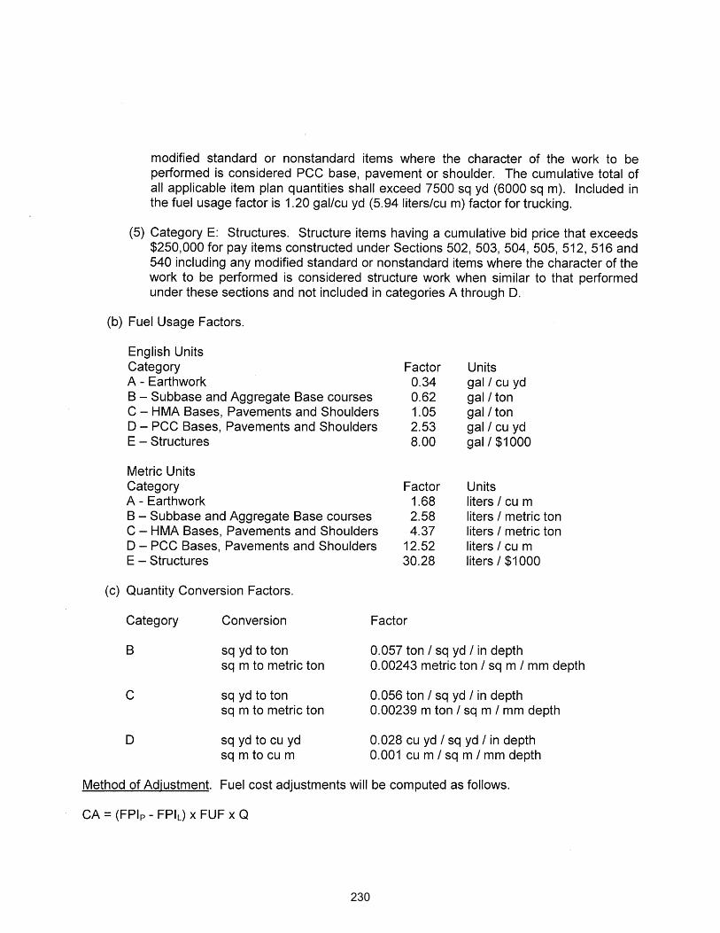
230
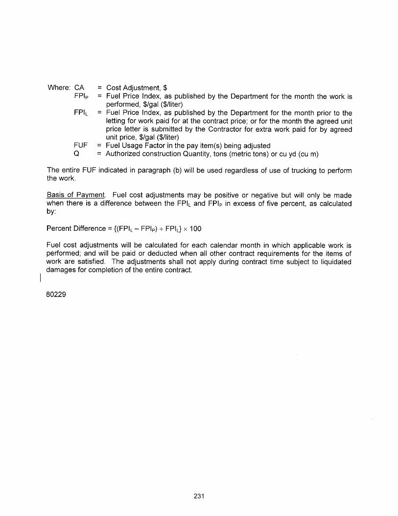
231

MANHOLES, VALVE VAULTS, AND FLAT SLAB TOPS (BDE) Effective: January 1, 2018 Revised: March 1, 2019 Description. In addition to those manufactured according to the current standards included in this contract, manholes, valve vaults, and flat slab tops manufactured prior to March 1, 2019, according to the previous Highway Standards listed below will be accepted on this contract: Product Previous Standards Precast Manhole Type A, 4’ (1.22 m) Diameter 602401-05 602401-04 602401-03 Precast Manhole Type A, 5’ (1.52 m) Diameter 602402-01 602402 602401-03 Precast Manhole Type A, 6’ (1.83 m) Diameter 602406-09 602406-08 602406-07 Precast Manhole Type A, 7’ (2.13 m) Diameter 602411-07 602411-06 602411-05 Precast Manhole Type A, 8’ (2.44 m) Diameter 602416-07 602416-06 602416-05 Precast Manhole Type A, 9’ (2.74 m) Diameter 602421-07 602421-06 602421-05 Precast Manhole Type A, 10’ (3.05 m) Diameter 602426-01 602426 Precast Valve Vault Type A, 4’ (1.22 m) Diameter 602501-04 602501-03 602501-02 Precast Valve Vault Type A, 5’ (1.52 m) Diameter 602506-01 602506 602501-02 Precast Reinforced Concrete Flat Slab Top 602601-05 602601-04 The following revisions to the Standard Specifications shall apply to manholes, valve vaults, and flat slab tops manufactured according to the current standards included in this contract: Revise Article 602.02(g) of the Standard Specifications to read:
“ (g) Structural Steel (Note 4) ....................................................................................... 1006.04
Note 4. All components of the manhole joint splice shall be galvanized according to the requirements of AASHTO M 111 or M 232 as applicable.”
Add the following to Article 602.02 of the Standard Specifications:
“ (s) Anchor Bolts and Rods (Note 5) ........................................................................... 1006.09
Note 5. The threaded rods for the manhole joint splice shall be according to the requirements of ASTM F 1554, Grade 55, (Grade 380).”
Revise the second paragraph of Article 1042.10 of the Standard Specifications to read:
“ Catch basin Types A, B, C, and D; Manhole Type A; Inlet Types A and B; Drainage Structures Types 1, 2, 3, 4, 5, and 6; Valve Vault Type A; and reinforced concrete flat slab top (Highway Standard 602601) shall be manufactured according to AASHTO M 199 (M 199M), except the minimum wall thickness shall be as shown on the plans. Additionally, catch basins, inlets, and drainage structures shall have a minimum concrete compressive strength of 4500 psi
232

(31,000 kPa) at 28 days and manholes, valve vaults, and reinforced concrete flat slab tops shall have a minimum concrete compressive strength of 5000 psi (34,500 kPa) at 28 days.” 80393
233

MOBILIZATION (BDE) Effective: April 1, 2020 Replace Articles 671.02(a), (b), and (c) of the Standard Specifications with the following:
“ (a) Upon execution of the contract, 90 percent of the pay item will be paid. (b) When 90 percent of the adjusted contract value is earned, the remaining ten percent of
the pay item will be paid along with any amount bid in excess of six percent of the original contract amount.”
80428
234

PORTLAND CEMENT CONCRETE – HAUL TIME (BDE) Effective: July 1, 2020 Revise Article 1020.11(a)(7) of the Standard Specifications to read:
“ (7) Haul Time. Haul time shall begin when the delivery ticket is stamped. The delivery ticket shall be stamped no later than five minutes after the addition of the mixing water to the cement, or after the addition of the cement to the aggregate when the combined aggregates contain free moisture in excess of two percent by weight (mass). If more than one batch is required for charging a truck using a stationary mixer, the time of haul shall start with mixing of the first batch. Haul time shall end when the truck is emptied for incorporation of the concrete into the work. The maximum haul time shall be as follows.
Concrete Temperature at Point of Discharge,
°F (°C)
Maximum Haul Time 1/ (minutes)
Truck Mixer or Truck Agitator
Nonagitator Truck
50 - 64 (10 - 17.5) 90 45 > 64 (> 17.5) - without retarder 60 30 > 64 (> 17.5) - with retarder 90 45
1/ To encourage start-up testing for mix adjustments at the plant, the first two trucks
will be allowed an additional 15 minutes haul time whenever such testing is performed.
For a mixture which is not mixed on the jobsite, a delivery ticket shall be required for each load. The following information shall be recorded on each delivery ticket: (1) ticket number; (2) name of producer and plant location; (3) contract number; (4) name of Contractor; (5) stamped date and time batched; (6) truck number; (7) quantity batched; (8) amount of admixture(s) in the batch; (9) amount of water in the batch; and (10) Department mix design number. For concrete mixed in jobsite stationary mixers, the above delivery ticket may be waived, but a method of verifying the haul time shall be established to the satisfaction of the Engineer.”
80430
235

PORTLAND CEMENT CONCRETE PAVEMENT PLACEMENT (BDE) Effective: July 1, 2020 Revise the fifth paragraph of Article 420.07 of the Standard Specifications to read:
“ The concrete shall be deposited uniformly across the subgrade or subbase as close as possible to its final position. The time elapsing from when the concrete is unloaded until it is incorporated into the work shall not exceed 20 minutes. When required, hand spreading shall be accomplished with shovels.” 80432
236
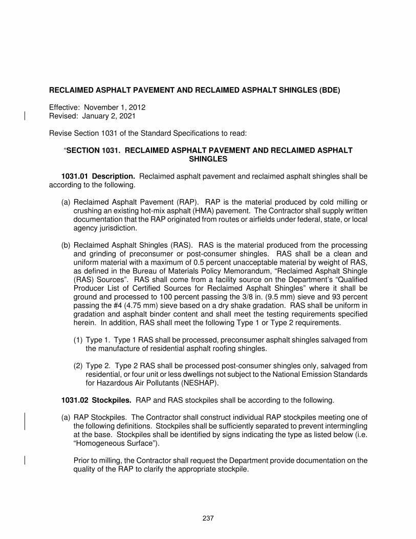
RECLAIMED ASPHALT PAVEMENT AND RECLAIMED ASPHALT SHINGLES (BDE) Effective: November 1, 2012 Revised: January 2, 2021 Revise Section 1031 of the Standard Specifications to read:
“SECTION 1031. RECLAIMED ASPHALT PAVEMENT AND RECLAIMED ASPHALT SHINGLES
1031.01 Description. Reclaimed asphalt pavement and reclaimed asphalt shingles shall be
according to the following. (a) Reclaimed Asphalt Pavement (RAP). RAP is the material produced by cold milling or
crushing an existing hot-mix asphalt (HMA) pavement. The Contractor shall supply written documentation that the RAP originated from routes or airfields under federal, state, or local agency jurisdiction.
(b) Reclaimed Asphalt Shingles (RAS). RAS is the material produced from the processing and grinding of preconsumer or post-consumer shingles. RAS shall be a clean and uniform material with a maximum of 0.5 percent unacceptable material by weight of RAS, as defined in the Bureau of Materials Policy Memorandum, “Reclaimed Asphalt Shingle (RAS) Sources”. RAS shall come from a facility source on the Department’s “Qualified Producer List of Certified Sources for Reclaimed Asphalt Shingles” where it shall be ground and processed to 100 percent passing the 3/8 in. (9.5 mm) sieve and 93 percent passing the #4 (4.75 mm) sieve based on a dry shake gradation. RAS shall be uniform in gradation and asphalt binder content and shall meet the testing requirements specified herein. In addition, RAS shall meet the following Type 1 or Type 2 requirements. (1) Type 1. Type 1 RAS shall be processed, preconsumer asphalt shingles salvaged from
the manufacture of residential asphalt roofing shingles.
(2) Type 2. Type 2 RAS shall be processed post-consumer shingles only, salvaged from residential, or four unit or less dwellings not subject to the National Emission Standards for Hazardous Air Pollutants (NESHAP).
1031.02 Stockpiles. RAP and RAS stockpiles shall be according to the following. (a) RAP Stockpiles. The Contractor shall construct individual RAP stockpiles meeting one of
the following definitions. Stockpiles shall be sufficiently separated to prevent intermingling at the base. Stockpiles shall be identified by signs indicating the type as listed below (i.e. “Homogeneous Surface”). Prior to milling, the Contractor shall request the Department provide documentation on the quality of the RAP to clarify the appropriate stockpile.
237

(1) Fractionated RAP (FRAP). FRAP shall consist of RAP from Class I, HMA (High and Low ESAL) mixtures. The coarse aggregate in FRAP shall be crushed aggregate and may represent more than one aggregate type and/or quality but shall be at least C quality. FRAP shall be fractionated prior to testing by screening into a minimum of two size fractions with the separation occurring on or between the No. 4 (4.75 mm) and 1/2 in. (12.5 mm) sieves. Agglomerations shall be minimized such that 100 percent of the RAP in the coarse fraction shall pass the maximum sieve size specified for the mixture composition of the mix design.
(2) Homogeneous. Homogeneous RAP stockpiles shall consist of RAP from Class I, HMA (High and Low ESAL) mixtures and represent: 1) the same aggregate quality, but shall be at least C quality; 2) the same type of crushed aggregate (either crushed natural aggregate, ACBF slag, or steel slag); 3) similar gradation; and 4) similar asphalt binder content. If approved by the Engineer, combined single pass surface/binder millings may be considered “homogeneous” with a quality rating dictated by the lowest coarse aggregate quality present in the mixture.
(3) Conglomerate. Conglomerate RAP stockpiles shall consist of RAP from Class I, HMA (High and Low ESAL) mixtures. The coarse aggregate in this RAP shall be crushed aggregate and may represent more than one aggregate type and/or quality but shall be at least C quality. This RAP may have an inconsistent gradation and/or asphalt binder content prior to processing. Conglomerate RAP shall be processed prior to testing by crushing to where all RAP shall pass the 5/8 in. (16 mm) or smaller screen. Conglomerate RAP stockpiles shall not contain steel slag.
(4) Conglomerate “D” Quality (Conglomerate DQ). Conglomerate DQ RAP stockpiles
shall be according to Articles 1031.02(a)(1)-1031.02(a)(3), except they may also consist of RAP from HMA shoulders, bituminous stabilized subbases, or HMA (High or Low ESAL) binder mixture. The coarse aggregate in this RAP may be crushed or round but shall be at least D quality. This RAP may have an inconsistent gradation and/or asphalt binder content.
(5) Non-Quality. RAP stockpiles that do not meet the requirements of the stockpile categories listed above shall be classified as “Non-Quality”.
RAP/FRAP containing contaminants, such as earth, brick, sand, concrete, sheet asphalt, non-bituminous surface treatment (i.e. high friction surface treatments), pavement fabric, joint sealants, plant cleanout, etc., will be unacceptable unless the contaminants are removed to the satisfaction of the Engineer. Sheet asphalt shall be stockpiled separately.
(b) RAS Stockpiles. Type 1 and Type 2 RAS shall be stockpiled separately and shall not be intermingled. Each stockpile shall be signed indicating what type of RAS is present. Unless otherwise specified by the Engineer, mechanically blending manufactured sand (FM 20 or FM 22) or fine FRAP up to an equal weight of RAS with the processed RAS will be permitted to improve workability. The sand shall be B quality or better from an
238

approved Aggregate Gradation Control System source. The sand shall be accounted for in the mix design and during HMA production. Records identifying the shingle processing facility supplying the RAS, RAS type, and lot number shall be maintained by project contract number and kept for a minimum of three years.
Additional processed RAP/FRAP/RAS shall be stockpiled in a separate working pile, as designated in the QC Plan, and only added to the original stockpile after the test results for the working pile are found to meet the requirements specified in Articles 1031.03 and 1031.04.
1031.03 Testing. RAP/FRAP and RAS testing shall be according to the following. (a) RAP/FRAP Testing. When used in HMA, the RAP/FRAP shall be sampled and tested
either during or after stockpiling. (1) During Stockpiling. For testing during stockpiling, washed extraction samples shall be
run at the minimum frequency of one sample per 500 tons (450 metric tons) for the first 2,000 tons (1,800 metric tons) and one sample per 2,000 tons (1,800 metric tons) thereafter. A minimum of five tests shall be required for stockpiles less than 4,000 tons (3,600 metric tons).
(2) After Stockpiling. For testing after stockpiling, the Contractor shall submit a plan for approval to the Department proposing a satisfactory method of sampling and testing the RAP/FRAP pile either in-situ or by restockpiling. The sampling plan shall meet the minimum frequency required above and detail the procedure used to obtain representative samples throughout the pile for testing.
Each sample shall be split to obtain two equal samples of test sample size. One of the two test samples from the final split shall be labeled and stored for Department use. The Contractor shall perform a washed extraction on the other test sample according to Illinois Modified AASHTO T 164. The Engineer reserves the right to test any sample (split or Department-taken) to verify Contractor test results.
(b) RAS Testing. RAS or RAS blended with manufactured sand shall be sampled and tested during stockpiling according to the Bureau of Materials Policy Memorandum, “Reclaimed Asphalt Shingle (RAS) Source”. Samples shall be collected during stockpiling at the minimum frequency of one sample per 200 tons (180 metric tons) for the first 1,000 tons (900 metric tons) and one sample per 500 tons (450 metric tons) or a minimum of once per week, whichever is more frequent, thereafter. A minimum of five samples are required for stockpiles less than 1,000 tons (900 metric tons). Before testing, each sample shall be split to obtain two test samples. One of the two test samples from the final split shall be labeled and stored for Department use. The
239

Contractor shall perform a washed extraction and test for unacceptable materials on the other test sample according to Illinois Modified AASHTO T 164. The Engineer reserves the right to test any sample (split or Department-taken) to verify Contractor test results. The Contractor shall obtain and make available all of the test results from the start of the original stockpile.
1031.04 Evaluation of Tests. Evaluation of test results shall be according to the following. (a) Limits of Precision. The limits of precision between the Contractor’s and the Department’s
split sample test results shall be according to the following.
Test Parameter Limits of Precision
% Passing RAP FRAP RAS
1/2 in. (12.5 mm) 6.0 % 5.0 % # 4 (4.75 mm) 6.0 % 5.0 % # 8 (2.36 mm) 4.0 % 3.0 % 4.0 % # 30 (600 µm) 3.0 % 2.0 % 4.0 % # 200 (75 µm) 2.5 % 2.2 % 4.0 % Asphalt Binder 0.4 % 0.3 % 3.0 % Gmm 0.035 0.030
If the test results are outside the above limits of precision, the Department will immediately investigate.
(b) Evaluation of RAP/FRAP Test Results. All of the extraction results shall be compiled and
averaged for asphalt binder content and gradation, and when applicable Gmm. Individual extraction test results, when compared to the averages, will be accepted if within the tolerances listed below.
Parameter FRAP/Homogeneous/
Conglomerate
1 in. (25 mm) 1/2 in. (12.5 mm) ± 8 % # 4 (4.75 mm) ± 6 % # 8 (2.36 mm) ± 5 % # 16 (1.18 mm) # 30 (600 µm) ± 5 % # 200 (75 µm) ± 2.0 %
Asphalt Binder ± 0.4 % 1/
Gmm ± 0.03 2/
1/ The tolerance for FRAP shall be ± 0.3 percent.
240

2/ For stockpile with slag or steel slag present as determined in the current Manual
of Test Procedures Appendix B 21, “Determination of Aggregate Bulk (Dry) Specific Gravity (Gsb) of Reclaimed Asphalt Pavement (RAP) and Reclaimed Asphalt Shingles (RAS)”.
If more than 20 percent of the test results for an individual parameter (individual sieves, Gmm, and/or asphalt binder content) are out of the above tolerances, the RAP/FRAP shall not be used in HMA unless the RAP/FRAP representing the failing tests is removed from the stockpile. All test data and acceptance ranges shall be sent to the Department for evaluation. With the approval of the Engineer, the ignition oven may be substituted for solvent extractions according to the document “Calibration of the Ignition Oven for the Purpose of Characterizing Reclaimed Asphalt Pavement (RAP)”.
(c) Evaluation of RAS and RAS Blended with Manufactured Sand or Fine FRAP Test Results. All of the test results, with the exception of percent unacceptable materials, shall be compiled and averaged for asphalt binder content and gradation. Individual test results, when compared to the averages, will be accepted if within the tolerances listed below.
Parameter RAS
# 8 (2.36 mm) ± 5 % # 16 (1.18 mm) ± 5 % # 30 (600 µm) ± 4 % # 200 (75 µm) ± 2.5 %
Asphalt Binder Content ± 2.0 % If more than 20 percent of the test results for an individual parameter (individual sieves and/or asphalt binder content) are out of the above tolerances, or if the unacceptable material exceeds 0.5 percent by weight of material retained on the No. 4 (4.75 mm) sieve, the RAS or RAS blend shall not be used in Department projects. All test data and acceptance ranges shall be sent to the Department for evaluation.
1031.05 Quality Designation of Aggregate in RAP/FRAP. (a) RAP. The aggregate quality of the RAP for homogeneous, conglomerate, and
conglomerate DQ stockpiles shall be set by the lowest quality of coarse aggregate in the RAP stockpile and are designated as follows. (1) RAP from Class I, HMA (High ESAL), or (Low ESAL) IL-9.5L surface mixtures are
designated as containing Class B quality coarse aggregate.
(2) RAP from Class I binder, HMA (High ESAL) binder, or (Low ESAL) IL-19.0L binder mixtures are designated as containing Class C quality coarse aggregate.
241

(3) RAP from BAM stabilized subbase and BAM shoulders are designated as containing
Class D quality coarse aggregate.
(b) FRAP. If the Engineer has documentation of the quality of the FRAP aggregate, the Contractor shall use the assigned quality provided by the Engineer. If the quality is not known, the quality shall be determined as follows. Coarse and fine FRAP stockpiles containing plus No. 4 (4.75 mm) sieve coarse aggregate shall have a maximum tonnage of 5,000 tons (4,500 metric tons). The Contractor shall obtain a representative sample witnessed by the Engineer. The sample shall be a minimum of 50 lb (25 kg). The sample shall be extracted according to Illinois Modified AASHTO T 164 by a consultant laboratory prequalified by the Department for the specified testing. The consultant laboratory shall submit the test results along with the recovered aggregate sample to the District Office. Consultant laboratory services will be at no additional cost to the Department. The District will forward the sample to the Central Bureau of Materials Aggregate Lab for MicroDeval Testing, according to ITP 327. A maximum loss of 15.0 percent will be applied for all HMA applications.
1031.06 Use of RAP/FRAP and/or RAS in HMA. The use of RAP/FRAP and/or RAS shall be the Contractor’s option when constructing HMA in all contracts.
(a) RAP/FRAP. The use of RAP/FRAP in HMA shall be as follows.
(1) Coarse Aggregate Size. The coarse aggregate in all RAP shall be equal to or less than the nominal maximum size requirement for the HMA mixture to be produced.
(2) Steel Slag Stockpiles. Homogeneous RAP stockpiles containing steel slag will be approved for use in all HMA (High ESAL and Low ESAL) surface and binder mixture applications.
(3) Use in HMA Surface Mixtures (High and Low ESAL). RAP/FRAP stockpiles for use in HMA surface mixtures (High and Low ESAL) shall be FRAP or homogeneous in which the coarse aggregate is Class B quality or better. FRAP from conglomerate stockpiles shall be considered equivalent to limestone for frictional considerations. Known frictional contributions from plus No. 4 (4.75 mm) homogeneous FRAP stockpiles will be accounted for in meeting frictional requirements in the specified mixture.
(4) Use in HMA Binder Mixtures (High and Low ESAL), HMA Base Course, and HMA Base Course Widening. RAP/FRAP stockpiles for use in HMA binder mixtures (High and Low ESAL), HMA base course, and HMA base course widening shall be FRAP, homogeneous, or conglomerate, in which the coarse aggregate is Class C quality or better.
(5) Use in Shoulders and Subbase. RAP/FRAP stockpiles for use in HMA shoulders and stabilized subbase (HMA) shall be FRAP, homogeneous, or conglomerate.
242

(6) When the Contractor chooses the RAP option, the percentage of RAP shall not exceed
the amounts indicated in Article 1031.06(c)(1) below for a given Ndesign. (b) RAS. RAS meeting Type 1 or Type 2 requirements will be permitted in all HMA
applications as specified herein. (c) RAP/FRAP and/or RAS Usage Limits. Type 1 or Type 2 RAS may be used alone or in
conjunction with RAP or FRAP in HMA mixtures up to a maximum of 5.0 percent by weight of the total mix.
(1) RAP/RAS. When RAP is used alone or RAP is used in conjunction with RAS, the
percentage of virgin asphalt binder replacement (ABR) shall not exceed the amounts listed in the following table.
HMA Mixtures - RAP/RAS Maximum ABR % 1/ 2/
Ndesign Binder Surface Polymer Modified Binder or Surface
30 30 30 10 50 25 15 10
70 15 10 10 90 10 10 10
1/ For Low ESAL HMA shoulder and stabilized subbase, the RAP/RAS ABR shall not
exceed 50 percent of the mixture. 2/ When RAP/RAS ABR exceeds 20 percent, the high and low virgin asphalt binder
grades shall each be reduced by one grade (i.e. 25 percent ABR would require a virgin asphalt binder grade of PG 64-22 to be reduced to a PG 58-28).
(2) FRAP/RAS. When FRAP is used alone or FRAP is used in conjunction with RAS, the percentage of virgin asphalt binder replacement shall not exceed the amounts listed in the following table.
HMA Mixtures - FRAP/RAS Maximum ABR % 1/ 2/
Ndesign Binder Surface Polymer Modified Binder or Surface
30 55 45 15 50 45 40 15
70 45 35 15 90 45 35 15
SMA - - - - 25
243

IL-4.75 - - - - 35 1/ For Low ESAL HMA shoulder and stabilized subbase, the FRAP/RAS ABR shall
not exceed 50 percent of the mixture.
2/ When FRAP/RAS ABR exceeds 20 percent for all mixes, the high and low virgin asphalt binder grades shall each be reduced by one grade (i.e. 25 percent ABR would require a virgin asphalt binder grade of PG 64-22 to be reduced to a PG 58-28).
1031.07 HMA Mix Designs. At the Contractor’s option, HMA mixtures may be constructed
utilizing RAP/FRAP and/or RAS material meeting the detailed requirements specified herein.
(a) RAP/FRAP and/or RAS. RAP/FRAP and/or RAS mix designs shall be submitted for verification. If additional RAP/FRAP and/or RAS stockpiles are tested and found that no more than 20 percent of the individual parameter test results, as defined in Article 1031.04, are outside of the control tolerances set for the original RAP/FRAP and/or RAS stockpile and HMA mix design, and meets all of the requirements herein, the additional RAP/FRAP and/or RAS stockpiles may be used in the original mix design at the percent previously verified.
(b) RAS. Type 1 and Type 2 RAS are not interchangeable in a mix design. The RAP, FRAP, and RAS stone bulk specific gravities (Gsb) shall be according to the
“Determination of Aggregate Bulk (Dry) Specific Gravity (Gsb) of Reclaimed Asphalt Pavement (RAP) and Reclaimed Asphalt Shingles (RAS)” procedure in the Department’s Manual of Test Procedures for Materials.
1031.08 HMA Production. HMA production utilizing RAP/FRAP and/or RAS shall be as
follows.
To remove or reduce agglomerated material, a scalping screen, gator, crushing unit, or comparable sizing device approved by the Engineer shall be used in the RAP/FRAP and/or RAS feed system to remove or reduce oversized material.
If the RAP/FRAP and/or RAS control tolerances or QC/QA test results require corrective
action, the Contractor shall cease production of the mixture containing RAP/FRAP and/or RAS and either switch to the virgin aggregate design or submit a new mix design.
(a) RAP/FRAP. The coarse aggregate in all RAP/FRAP used shall be equal to or less than
the nominal maximum size requirement for the HMA mixture being produced.
(b) RAS. RAS shall be incorporated into the HMA mixture either by a separate weight depletion system or by using the RAP weigh belt. Either feed system shall be interlocked with the aggregate feed or weigh system to maintain correct proportions for all rates of production and batch sizes. The portion of RAS shall be controlled accurately to within
244

± 0.5 percent of the amount of RAS utilized. When using the weight depletion system, flow indicators or sensing devices shall be provided and interlocked with the plant controls such that the mixture production is halted when RAS flow is interrupted.
(c) RAP/FRAP and/or RAS. HMA plants utilizing RAP/FRAP and/or RAS shall be capable of automatically recording and printing the following information. (1) Dryer Drum Plants.
a. Date, month, year, and time to the nearest minute for each print. b. HMA mix number assigned by the Department. c. Accumulated weight of dry aggregate (combined or individual) in tons (metric tons)
to the nearest 0.1 ton (0.1 metric ton). d. Accumulated dry weight of RAP/FRAP/RAS in tons (metric tons) to the nearest
0.1 ton (0.1 metric ton). e. Accumulated mineral filler in revolutions, tons (metric tons), etc. to the nearest
0.1 unit. f. Accumulated asphalt binder in gallons (liters), tons (metric tons), etc. to the nearest
0.1 unit. g. Residual asphalt binder in the RAP/FRAP/RAS material as a percent of the total
mix to the nearest 0.1 percent. h. Aggregate and RAP/FRAP/RAS moisture compensators in percent as set on the
control panel. (Required when accumulated or individual aggregate and RAP/FRAP/RAS are recorded in a wet condition.)
i. A positive dust control system shall be utilized when the combined contribution of
reclaimed material passing the No. 200 sieve exceeds 1.5 percent.
(2) Batch Plants. a. Date, month, year, and time to the nearest minute for each print. b. HMA mix number assigned by the Department. c. Individual virgin aggregate hot bin batch weights to the nearest pound (kilogram). d. Mineral filler weight to the nearest pound (kilogram). e. RAP/FRAP/RAS weight to the nearest pound (kilogram).
245

f. Virgin asphalt binder weight to the nearest pound (kilogram). g. Residual asphalt binder in the RAP/FRAP/RAS material as a percent of the total
mix to the nearest 0.1 percent. The printouts shall be maintained in a file at the plant for a minimum of one year or as directed by the Engineer and shall be made available upon request. The printing system will be inspected by the Engineer prior to production and verified at the beginning of each construction season thereafter.
1031.09 RAP in Aggregate Applications. RAP in aggregate applications shall be according
to the Bureau of Materials Policy Memorandum, “Reclaimed Asphalt Pavement (RAP) for Aggregate Applications” and the following.
(a) RAP in Aggregate Surface Course and Aggregate Wedge Shoulders, Type B. The use of
RAP in aggregate surface course (temporary access entrances only) and aggregate wedge shoulders, Type B shall be as follows.
(1) Stockpiles and Testing. RAP stockpiles may be any of those listed in Article 1031.02,
except “Non-Quality” and “FRAP”. The testing requirements of Article 1031.03 shall not apply.
(2) Gradation. One hundred percent of the RAP material shall pass the 1 1/2 in.
(37.5 mm) sieve. The RAP material shall be reasonably well graded from coarse to fine. RAP material that is gap-graded or single sized will not be accepted.
(b) RAP in Aggregate Subgrade Improvement (ASI). RAP in ASI shall be according to
Article 1031.06, except “Conglomerate DQ” and “Non-Quality” may be used.”
80306
246

REMOVAL AND DISPOSAL OF REGULATED SUBSTANCES (BDE) Effective: January 1, 2019 Revised: January 1, 2020 Revise Section 669 of the Standard Specifications to read:
“SECTION 669. REMOVAL AND DISPOSAL OF REGULATED SUBSTANCES
669.01 Description. This work shall consist of the transportation and proper disposal of regulated substances. This work shall also consist of the removal, transportation, and proper disposal of underground storage tanks (UST), their contents and associated underground piping to the point where the piping is above the ground, including determining the content types and estimated quantities.
669.02 Equipment. The Contractor shall notify the Engineer of the delivery of all excavation,
storage, and transportation equipment to a work area location. The equipment shall comply with OSHA and American Petroleum Institute (API) guidelines and shall be furnished in a clean condition. Clean condition means the equipment does not contain any residual material classified as a non-special waste, non-hazardous special waste, or hazardous waste. Residual materials include, but are not limited to, petroleum products, chemical products, sludges, or any other material present in or on equipment.
Before beginning any associated soil or groundwater management activity, the Contractor
shall provide the Engineer with the opportunity to visually inspect and approve the equipment. If the equipment contains any contaminated residual material, decontamination shall be performed on the equipment as appropriate to the regulated substance and degree of contamination present according to OSHA and API guidelines. All cleaning fluids used shall be treated as the contaminant unless laboratory testing proves otherwise.
669.03 Pre-Construction Submittals and Qualifications. Prior to beginning this work, or
working in areas with regulated substances, the Contractor shall submit a “Regulated Substances Pre-Construction Plan (RSPCP)” to the Engineer for review and approval using form BDE 2730. The form shall be signed by an Illinois licensed Professional Engineer or Professional Geologist.
As part of the RSPCP, the Contractor(s) or firm(s) performing the work shall meet the following
qualifications. (a) Regulated Substances Monitoring. Qualification for environmental observation and field
screening of regulated substances work and environmental observation of UST removal shall require either pre-qualification in Hazardous Waste by the Department or demonstration of acceptable project experience in remediation and operations for contaminated sites in accordance with applicable Federal, State, or local regulatory requirements using BDE 2730.
247

Qualification for each individual performing regulated substances monitoring shall require a minimum of one-year of experience in similar activities as those required for the project.
(b) Underground Storage Tank Removal. Qualification for underground storage tank (UST) removal work shall require licensing and certification with the Office of the State Fire Marshall (OSFM) and possession of all permits required to perform the work. A copy of the permit shall be provided to the Engineer prior to tank removal.
The qualified Contractor(s) or firm(s) shall also document it does not have any current or former ties with any of the properties contained within, adjoining, or potentially affecting the work.
The Engineer will require up to 21 calendar days for review of the RSPCP. The review may
involve rejection or revision and resubmittal; in which case, an additional 21 days will be required for each subsequent review. Work shall not commence until the RSPCP has been approved by the Engineer. After approval, the RSPCP shall be revised as necessary to reflect changed conditions in the field and documented using BDE 2730A “Regulated Substances Pre-Construction Plan (RSPCP) Addendum” and submitted to the Engineer for approval.
CONSTRUCTION REQUIREMENTS
669.04 Regulated Substances Monitoring. Regulated substances monitoring includes environmental observation and field screening during regulated substances management activities at the contract specific work areas. As part of the regulated substances monitoring, the monitoring personnel shall perform and document the applicable duties listed on form BDE 2732 “Regulated Substances Monitoring Daily Record (RSMDR)”.
(a) Environmental Observation. Prior to beginning excavation, the Contractor shall mark the
limits of the contract specific work areas. Once work begins, the monitoring personnel shall be present on-site continuously during the excavation and loading of material.
(b) Field Screening. Field screening shall be performed during the excavation and loading of material from the contract specific work areas, except for material classified according to Article 669.05(b)(1) or 669.05(c) where field screening is not required.
Field screening shall be performed with either a photoionization detector (PID) (minimum 10.6eV lamp) or a flame ionization detector (FID), and other equipment as appropriate, to monitor for potential contaminants associated with regulated substances. The PID or FID shall be calibrated on-site, and background level readings taken and recorded daily, and as field and weather conditions change. Field screen readings on the PID or FID in excess of background levels indicates the potential presence of regulated substances requiring handling as a non-special waste, special waste, or hazardous waste. PID or FID readings may be used as the basis of increasing the limits of removal with the approval of the Engineer but shall in no case be used to decrease the limits.
248

669.05 Regulated Substances Management and Disposal. The management and disposal of soil and/or groundwater containing regulated substances shall be according to the following:
(a) Soil Analytical Results Exceed Most Stringent MAC. When the soil analytical results
indicate detected levels exceed the most stringent maximum allowable concentration (MAC) for chemical constituents in soil established pursuant to Subpart F of 35 Ill. Adm. Code 1100.605, the soil shall be managed as follows: (1) When analytical results indicate inorganic chemical constituents exceed the most
stringent MAC, but still considered within area background levels by the Engineer, the excavated soil can be utilized within the right-of-way as embankment or fill, when suitable. If the soils cannot be utilized within the right-of-way, they shall be managed and disposed of at a landfill as a non-special waste.
(2) When analytical results indicate inorganic chemical constituents exceed the most stringent MAC but do not exceed the MAC for a Metropolitan Statistical Area (MSA) County identified in 35 Ill. Admin. Code 742 Appendix A. Table G, the excavated soil can be utilized within the right-of-way as embankment or fill, when suitable, or managed and disposed of at a clean construction and demolition debris (CCDD) facility or an uncontaminated soil fill operation (USFO) within an MSA County provided the pH of the soil is within the range of 6.25 - 9.0, inclusive.
(3) When analytical results indicate chemical constituents exceed the most stringent MAC but do not exceed the MAC for an MSA County excluding Chicago, or the MAC within the Chicago corporate limits, the excavated soil can be utilized within the right-of-way as embankment or fill, when suitable, or managed and disposed of off-site at a CCDD facility or an USFO within an MSA County excluding Chicago or within the Chicago corporate limits provided the pH of the soil is within the range of 6.25 - 9.0, inclusive.
(4) When analytical results indicate chemical constituents exceed the most stringent MAC but do not exceed the MAC for an MSA County excluding Chicago, the excavated soil can be utilized within the right-of-way as embankment or fill, when suitable, or managed and disposed of off-site at a CCDD facility or an USFO within an MSA County excluding Chicago provided the pH of the soil is within the range of 6.25 - 9.0, inclusive.
(5) When the Engineer determines soil cannot be managed according to Articles 669.05(a)(1) through (a)(4) above and the materials do not contain special waste or hazardous waste, as determined by the Engineer, the soil shall be managed and disposed of at a landfill as a non-special waste.
(6) When analytical results indicate soil is hazardous by characteristic or listing pursuant
to 35 Ill. Admin. Code 721, contains radiological constituents, or the Engineer otherwise determines the soil cannot be managed according to Articles 669.05(a)(1)
249

through (a)(5) above, the soil shall be managed and disposed of off-site as a special waste or hazardous waste as applicable.
(b) Soil Analytical Results Do Not Exceed Most Stringent MAC. When the soil analytical results indicate that detected levels do not exceed the most stringent MAC, the excavated soil can be utilized within the right-of-way as embankment or fill, when suitable, or managed and disposed of off-site according to Article 202.03. However, the excavated soil cannot be taken to a CCDD facility or an USFO for any of the following reasons. (1) The pH of the soil is less than 6.25 or greater than 9.0.
(2) The soil exhibited PID or FID readings in excess of background levels.
(c) Soil Analytical Results Exceed Most Stringent MAC but Do Not Exceed Tiered Approach
to Corrective Action Objectives (TACO) Residential. When the soil analytical results indicate that detected levels exceed the most stringent MAC but do not exceed TACO Tier 1 Soil Remediation Objectives for Residential Properties pursuant to 35 Ill. Admin. Code 742 Appendix B Table A, the excavated soil can be utilized within the right-of-way as embankment or fill, when suitable, or managed and disposed of off-site according to Article 202.03. However, the excavated soil cannot be taken to a CCDD facility or an USFO.
(d) Groundwater. When groundwater analytical results indicate the detected levels are above Appendix B, Table E of 35 Ill. Admin. Code 742, the most stringent Tier 1 Groundwater Remediation Objectives for Groundwater Component of the Groundwater Ingestion Route for Class 1 groundwater, the groundwater shall be managed off-site as a special waste or hazardous waste as applicable. Special waste groundwater shall be containerized and trucked to an off-site treatment facility, or may be discharged to a sanitary sewer or combined sewer when permitted by the local sewer authority. Groundwater discharged to a sanitary sewer or combined sewer shall be pre-treated to remove particulates and measured with a calibrated flow meter to comply with applicable discharge limits. A copy of the permit shall be provided to the Engineer prior to discharging groundwater to the sanitary sewer or combined sewer. Groundwater encountered within trenches may be managed within the trench and allowed to infiltrate back into the ground. If the groundwater cannot be managed within the trench, it may be discharged to a sanitary sewer or combined sewer when permitted by the local sewer authority, or it shall be containerized and trucked to an off-site treatment facility as a special waste or hazardous waste. The Contractor is prohibited from discharging groundwater within the trench through a storm sewer. The Contractor shall install backfill plugs within the area of groundwater contamination. One backfill plug shall be placed down gradient to the area of groundwater contamination. Backfill plugs shall be installed at intervals not to exceed 50 ft (15 m). Backfill plugs are to be 4 ft (1.2 m) long, measured parallel to the trench, full trench width and depth. Backfill plugs shall not have any fine aggregate bedding or backfill, but shall be entirely cohesive
250

soil or any class of concrete. The Contractor shall provide test data that the material has a permeability of less than 10-7 cm/sec according to ASTM D 5084, Method A or per another test method approved by the Engineer.
The Contractor shall use due care when transferring contaminated material from the area of origin to the transporter. Should releases of contaminated material to the environment occur (i.e., spillage onto the ground, etc.), the Contractor shall clean-up spilled material and place in the appropriate storage containers as previously specified. Clean-up shall include, but not be limited to, sampling beneath the material staging area to determine complete removal of the spilled material.
The Contractor shall provide engineered barriers, when required, and shall include materials
sufficient to completely line excavation surfaces, including sloped surfaces, bottoms, and sidewall faces, within the areas designated for protection.
The Contractor shall obtain all documentation including any permits and/or licenses required
to transport the material containing regulated substances to the disposal facility. The Contractor shall coordinate with the Engineer on the completion of all documentation. The Contractor shall make all arrangements for collection and analysis of landfill acceptance testing. The Contractor shall coordinate waste disposal approvals with the disposal facility.
The Contractor shall provide the Engineer with all transport-related documentation within two
days of transport or receipt of said document(s). For management of special or hazardous waste, the Contractor shall provide the Engineer with documentation that the Contractor is operating with a valid Illinois special waste transporter permit at least two weeks before transporting the first load of contaminated material.
Transportation and disposal of material classified according to Article 669.05(a)(5) or
669.05(a)(6) shall be completed each day so that none of the material remains on-site by the close of business, except when temporary staging has been approved.
Any waste generated as a special or hazardous waste from a non-fixed facility shall be
manifested off-site using the Department's county generator number provided by the Bureau of Design and Environment. An authorized representative of the Department shall sign all manifests for the disposal of the contaminated material and confirm the Contractor's transported volume. Any waste generated as a non-special waste may be managed off-site without a manifest, a special waste transporter, or a generator number.
The Contractor shall select a landfill permitted for disposal of the contaminant within the State
of Illinois. The Department will review and approve or reject the facility proposed by the Contractor to use as a landfill. The Contractor shall verify whether the selected disposal facility is compliant with those applicable standards as mandated by their permit and whether the disposal facility is presently, has previously been, or has never been, on the United States Environmental Protection Agency (U.S. EPA) National Priorities List or the Resource Conservation and Recovery Act (RCRA) List of Violating Facilities. The use of a Contractor selected landfill shall in no manner delay the construction schedule or alter the Contractor's responsibilities as set forth.
251

669.06 Non-Special Waste Certification. An authorized representative of the Department
shall sign and date all non-special waste certifications. The Contractor shall be responsible for providing the Engineer with the required information that will allow the Engineer to certify the waste is not a special waste.
(a) Definition. A waste is considered a non-special waste as long as it is not:
(1) a potentially infectious medical waste;
(2) a hazardous waste as defined in 35 Ill. Admin. Code 721;
(3) an industrial process waste or pollution control waste that contains liquids, as
determined using the paint filter test set forth in subdivision (3)(A) of subsection (m) of 35 Ill. Admin. Code 811.107;
(4) a regulated asbestos-containing waste material, as defined under the National Emission Standards for Hazardous Air Pollutants in 40 CFR Part 61.141;
(5) a material containing polychlorinated biphenyls (PCB's) regulated pursuant to 40 CFR Part 761;
(6) a material subject to the waste analysis and recordkeeping requirements of 35 Ill. Admin. Code 728.107 under land disposal restrictions of 35 Ill. Admin. Code 728;
(7) a waste material generated by processing recyclable metals by shredding and required to be managed as a special waste under Section 22.29 of the Environmental Protection Act; or
(8) an empty portable device or container in which a special or hazardous waste has been stored, transported, treated, disposed of, or otherwise handled.
(b) Certification Information. All information used to determine the waste is not a special waste shall be attached to the certification. The information shall include but not be limited to: (1) the means by which the generator has determined the waste is not a hazardous waste;
(2) the means by which the generator has determined the waste is not a liquid;
(3) if the waste undergoes testing, the analytic results obtained from testing, signed and
dated by the person responsible for completing the analysis;
(4) if the waste does not undergo testing, an explanation as to why no testing is needed;
252

(5) a description of the process generating the waste; and
(6) relevant material safety data sheets.
669.07 Temporary Staging. Soil classified according to Articles 669.05(a)(2), (b)(1), or (c) may be temporarily staged at the Contractor’s option. Soil classified according to Articles 669.05(a)(1), (a)(3), (a)(4), (a)(5), (a)(6), or (b)(2) shall be managed and disposed of without temporary staging to the greatest extent practicable. If circumstances beyond the Contractor’s control require temporary staging of these latter materials, the Contractor shall request approval from the Engineer in writing.
Temporary staging shall be accomplished within the right-of-way and the Contractor’s means
and methods shall be described in the approved or amended RSPCP. Staging areas shall not be located within 200 feet (61 m) of a public or private water supply well; nor within 100 feet (30 m) of sensitive environmental receptor areas, including wetlands, rivers, streams, lakes, or designated habitat zones.
The method of staging shall consist of containerization or stockpiling as applicable for the
type, classification, and physical state (i.e., liquid, solid, semisolid) of the material. Materials of different classifications shall be staged separately with no mixing or co-mingling.
When containers are used, the containers and their contents shall remain intact and
inaccessible to unauthorized persons until the manner of disposal is determined. The Contractor shall be responsible for all activities associated with the storage containers including, but not limited to, the procurement, transport, and labeling of the containers. The Contractor shall not use a storage container if visual inspection of the container reveals the presence of free liquids or other substances that could cause the waste to be reclassified as a hazardous or special waste.
When stockpiles are used, they shall be covered with a minimum 20-mil plastic sheeting or
tarps secured using weights or tie-downs. Perimeter berms or diversionary trenches shall be provided to contain and collect for disposal any water that drains from the soil. Stockpiles shall be managed to prevent or reduce potential dust generation.
When staging non-special waste, special waste, or hazardous waste, the following additional
requirements shall apply: (a) Non-Special Waste. When stockpiling soil classified according to Article 669.05(a)(1) or
669.05(a)(5), an impermeable surface barrier between the materials and the ground surface shall be installed. The impermeable barrier shall consist of a minimum 20-mil plastic liner material and the surface of the stockpile area shall be clean and free of debris prior to placement of the liner. Measures shall also be taken to limit or discourage access to the staging area.
(b) Special Waste and Hazardous Waste. Soil classified according to Article 669.05(a)(6) shall not be stockpiled but shall be containerized immediately upon generation in containers, tanks or containment buildings as defined by RCRA, Toxic Substances Control
253

Act (TSCA), and other applicable State or local regulations and requirements, including 35 Ill. Admin. Code Part 722, Standards Applicable to Generators of Hazardous Waste. The staging area(s) shall be enclosed (by a fence or other structure) to restrict direct access to the area, and all required regulatory identification signs applicable to a staging area containing special waste or hazardous waste shall be deployed. Storage containers shall be placed on an all-weather gravel-packed, asphalt, or concrete surface. Containers shall be in good condition and free of leaks, large dents, or severe rusting, which may compromise containment integrity. Containers must be constructed of, or lined with, materials that will not react or be otherwise incompatible with the hazardous or special waste contents. Containers used to store liquids shall not be filled more than 80 percent of the rated capacity. Incompatible wastes shall not be placed in the same container or comingled. All containers shall be legibly labeled and marked using pre-printed labels and permanent marker in accordance with applicable regulations, clearly showing the date of waste generation, location and/or area of waste generation, and type of waste. The Contractor shall place these identifying markings on an exterior side surface of the container. Storage containers shall be kept closed, and storage pads covered, except when access is needed by authorized personnel. Special waste and hazardous waste shall be transported and disposed within 90 days from the date of generation.
669.08 Underground Storage Tank Removal. For the purposes of this section, an
underground storage tank (UST) includes the underground storage tank, piping, electrical controls, pump island, vent pipes and appurtenances.
Prior to removing an UST, the Engineer shall determine whether the Department is considered
an "owner" or "operator" of the UST as defined by the UST regulations (41 Ill. Adm. Code Part 176). Ownership of the UST refers to the Department's owning title to the UST during storage, use or dispensing of regulated substances. The Department may be considered an "operator" of the UST if it has control of, or has responsibility for, the daily operation of the UST. The Department may however voluntarily undertake actions to remove an UST from the ground without being deemed an "operator" of the UST.
In the event the Department is deemed not to be the "owner" or "operator" of the UST, the
OSFM removal permit shall reflect who was the past "owner" or "operator" of the UST. If the "owner" or "operator" cannot be determined from past UST registration documents from OSFM, then the OSFM removal permit will state the "owner" or "operator" of the UST is the Department. The Department’s Office of Chief Counsel (OCC) will review all UST removal permits prior to submitting any removal permit to the OSFM. If the Department is not the “owner” or “operator” of the UST then it will not register the UST or pay any registration fee.
254

The Contractor shall be responsible for obtaining permits required for removing the UST, notification to the OSFM, using an OSFM certified tank contractor, removal and disposal of the UST and its contents, and preparation and submittal of the OSFM Site Assessment Report in accordance with 41 Ill. Admin. Code Part 176.330.
The Contractor shall contact the Engineer and the OSFM's office at least 72 hours prior to
removal to confirm the OSFM inspector's presence during the UST removal. Removal, transport, and disposal of the UST shall be according to the applicable portions of the latest revision of the "American Petroleum Institute (API) Recommended Practice 1604".
The Contractor shall collect and analyze tank content (sludge) for disposal purposes. The
Contractor shall remove as much of the regulated substance from the UST system as necessary to prevent further release into the environment. All contents within the tank shall be removed, transported and disposed of, or recycled. The tank shall be removed and rendered empty according to IEPA definition.
The Contractor shall collect soil samples from the bottom and sidewalls of the excavated area
in accordance with 35 Ill. Admin. Code Part 734.210(h) after the required backfill has been removed during the initial response action, to determine the level of contamination remaining in the ground, regardless if a release is confirmed or not by the OSFM on-site inspector.
In the event the UST is designated a leaking underground storage tank (LUST) by the OSFM’s
inspector, or confirmation by analytical results, the Contractor shall notify the Engineer and the District Environmental Studies Unit (DESU). Upon confirmation of a release of contaminants and notifications to the Engineer and DESU, the Contractor shall report the release to the Illinois Emergency Management Agency (IEMA) (e.g., by telephone or electronic mail) and provide them with whatever information is available (“owner” or “operator” shall be stated as the past registered “owner” or “operator”, or the IDOT District in which the tank is located and the DESU Manager).
The Contractor shall perform the following initial response actions if a release is indicated by
the OSFM inspector: (a) Take immediate action to prevent any further release of the regulated substance to the
environment, which may include removing, at the Engineer’s discretion, and disposing of up to 4 ft (1.2 m) of the contaminated material, as measured from the outside dimension of the tank;
(b) Identify and mitigate fire, explosion and vapor hazards;
(c) Visually inspect any above ground releases or exposed below ground releases and prevent further migration of the released substance into surrounding soils and groundwater; and
(d) Continue to monitor and mitigate any additional fire and safety hazards posed by vapors and free product that have migrated from the tank excavation zone and entered into subsurface structures (such as sewers or basements).
255

The tank excavation shall be backfilled according to applicable portions of Sections 205, 208,
and 550 with a material that will compact and develop stability. All uncontaminated concrete and soil removed during tank extraction may be used to backfill the excavation, at the discretion of the Engineer.
After backfilling the excavation, the site shall be graded and cleaned. 669.09 Regulated Substances Final Construction Report. Not later than 90 days after
completing this work, the Contractor shall submit a “Regulated Substances Final Construction Report (RSFCR)” to the Engineer using form BDE 2733 and required attachments. The form shall be signed by an Illinois licensed Professional Engineer or Professional Geologist.
669.10 Method of Measurement. Non-special waste, special waste, and hazardous waste
soil will be measured for payment according to Article 202.07(b) when performing earth excavation, Article 502.12(b) when excavating for structures, or by computing the volume of the trench using the maximum trench width permitted and the actual depth of the trench.
Groundwater containerized and transported off-site for management, storage, and disposal
will be measured for payment in gallons (liters). Backfill plugs will be measured in cubic yards (cubic meters) in place, except the quantity for
which payment will be made shall not exceed the volume of the trench, as computed by using the maximum width of trench permitted by the Specifications and the actual depth of the trench, with a deduction for the volume of the pipe.
Engineered Barriers will be measured for payment in square yards (square meters). 669.11 Basis of Payment. The work of preparing, submitting and administering a Regulated
Substances Pre-Construction Plan will be paid for at the contract lump sum price for REGULATED SUBSTANCES PRE-CONSTRUCTION PLAN.
Regulated substances monitoring, including completion of form BDE 2732 for each day of
work, will be paid for at the contract unit price per calendar day, or fraction thereof to the nearest 0.5 calendar day, for REGULATED SUBSTANCES MONITORING.
The installation of engineered barriers will be paid for at the contract unit price per square
yard (square meter) for ENGINEERED BARRIER. The work of UST removal, soil excavation, soil and content sampling, the management of
excavated soil and UST content, and UST disposal, will be paid for at the contract unit price per each for UNDERGROUND STORAGE TANK REMOVAL.
The transportation and disposal of soil and other materials from an excavation determined to
be contaminated will be paid for at the contract unit price per cubic yard (cubic meter) for
256

NON-SPECIAL WASTE DISPOSAL, SPECIAL WASTE DISPOSAL, or HAZARDOUS WASTE DISPOSAL.
The transportation and disposal of groundwater from an excavation determined to be
contaminated will be paid for at the contract unit price per gallon (liter) for SPECIAL WASTE GROUNDWATER DISPOSAL or HAZARDOUS WASTE GROUNDWATER DISPOSAL. When groundwater is discharged to a sanitary or combined sewer by permit, the cost will be paid for according to Article 109.05.
Backfill plugs will be paid for at the contract unit price per cubic yard (cubic meter) for
BACKFILL PLUGS. Payment for temporary staging of soil classified according to Articles 669.05(a)(1), (a)(3),
(a)(4), (a)(5), (a)(6), or (b)(2) will be paid for according to Article 109.04. The Department will not be responsible for any additional costs incurred, if mismanagement of the staging area, storage containers, or their contents by the Contractor results in excess cost expenditure for disposal or other material management requirements.
Payment for accumulated stormwater removal and disposal will be according to
Article 109.04. Payment will only be allowed if appropriate stormwater and erosion control methods were used.
Payment for decontamination, labor, material, and equipment for monitoring areas beyond the
specified areas, with the Engineer's prior written approval, will be according to Article 109.04.
When the waste material for disposal requires sampling for landfill disposal acceptance, the samples shall be analyzed for TCLP VOCs, SVOCs, RCRA metals, pH, ignitability, and paint filter test. The analysis will be paid for at the contract unit price per each for SOIL DISPOSAL ANALYSIS using EPA Methods 1311 (extraction), 8260B for VOCs, 8270C for SVOCs, 6010B and 7470A for RCRA metals, 9045C for pH, 1030 for ignitability, and 9095A for paint filter.
The work of preparing, submitting and administering a Regulated Substances Final
Construction Report will be paid for at the contract lump sum price REGULATED SUBSTANCES FINAL CONSTRUCTION REPORT.” 80407
257

SILT FENCE, INLET FILTERS, GROUND STABILIZATION AND RIPRAP FILTER FABRIC (BDE) Effective: November 1, 2019 Revised: July 1, 2021 Revise Article 280.02(m) and add Article 280.02(n) so the Standard Specifications read:
“ (m) Above Grade Inlet Filter (Fitted)....................................................................... 1081.15(j) (n) Above Grade Inlet Filter (Non-Fitted) ............................................................... 1081.15(k)”
Revise the last sentence of the first paragraph in Article 280.04(c) of the Standard Specifications to read:
“ The protection shall be constructed with hay or straw bales, silt filter fence, above grade inlet filters (fitted and non-fitted), or inlet filters.
Revise the first sentence of the second paragraph in Article 280.04(c) of the Standard Specifications to read:
“ When above grade inlet filters (fitted and non-fitted) are specified, they shall be of sufficient size to completely span and enclose the inlet structure.”
Revise Article 1080.02 of the Standard Specifications to read:
“ 1080.02 Geotextile Fabric. The fabric for silt filter fence shall consist of woven fabric meeting the requirements of AASHTO M 288 for unsupported silt fence.
The fabric for ground stabilization shall consist of woven yarns or nonwoven filaments of polyolefins or polyesters. Woven fabrics shall be Class 2 and nonwoven fabrics shall be Class 1 according to AASHTO M 288.
The physical properties for silt fence and ground stabilization fabrics shall be according to the
following.
258

PHYSICAL PROPERTIES
Silt Fence Woven 1/
Ground Stabilization
Woven 2/
Ground Stabilization Nonwoven 2/
Grab Strength, lb (N) 3/ ASTM D 4632
123 (550) MD 101 (450) XD
247 (1100) min. 4/ 202 (900) min. 4/
Elongation/Grab Strain, % ASTM D 4632 4/
49 max. 49 max. 50 min.
Trapezoidal Tear Strength, lb (N) ASTM D 4533 4/
-- 90 (400) min. 79 (350) min.
Puncture Strength, lb (N) ASTM D 6241 4/
-- 494 (2200) min. 433 (1925) min.
Apparent Opening Size, Sieve No. (mm) ASTM D 4751 5/
30 (0.60) max. 40 (0.43) max. 40 (0.43) max.
Permittivity, sec-1 ASTM D 4491
0.05 min.
Ultraviolet Stability, % retained strength after 500 hours of exposure ASTM D 4355
70 min. 50 min. 50 min.
1/ NTPEP results or manufacturer’s certification to meet test requirements. 2/ NTPEP results to meet test requirements. Manufacturer shall have public release
status and current reports on laboratory results in Test Data of NTPEP’s DataMine. 3/ MD = Machine direction. XD = Cross-machine direction. 4/ Values represent the minimum average roll value (MARV) in the weaker principle
direction, MD or XD. 5/ Values represent the maximum average roll value.”
Revise Article 1080.03 of the Standard Specifications to read:
“ 1080.03 Filter Fabric. The filter fabric shall consist of woven yarns or nonwoven filaments of polyolefins or polyesters. Woven fabrics shall be Class 3 for riprap gradations RR 4 and RR 5, and Class 2 for RR 6 and RR 7 according to AASHTO M 288. Woven slit film geotextiles (i.e. geotextiles made from yarns of a flat, tape-like character) shall not be permitted. Nonwoven fabrics shall be Class 2 for riprap gradations RR 4 and RR 5, and Class 1 for RR 6 and RR 7 according to AASHTO M 288. After forming, the fabric shall be processed so that the yarns or filaments retain their relative positions with respect to each other. The fabric shall be new and undamaged.
259

The filter fabric shall be manufactured in widths of not less than 6 ft (2 m). Sheets of fabric may be sewn together with thread of a material meeting the chemical requirements given for the yarns or filaments to form fabric widths as required. The sheets of filter fabric shall be sewn together at the point of manufacture or another approved location.
The filter fabric shall be according to the following.
PHYSICAL PROPERTIES 1/
Gradation Nos. RR 4 & RR 5
Gradation Nos. RR 6 & RR 7
Woven Nonwoven Woven Nonwoven Grab Strength, lb (N) ASTM D 4632 2/
180 (800) min.
157 (700) min.
247 (1100) min.
202 (900) min.
Elongation/Grab Strain, % ASTM D 4632 2/
49 max. 50 min. 49 max. 50 min.
Trapezoidal Tear Strength, lb (N) ASTM D 4533 2/
67 (300) min.
56 (250) min.
90 (400) min.
79 (350) min.
Puncture Strength, lb (N) ASTM D 6241 2/
370 (1650) min.
309 (1375) min.
494 (2200) min.
433 (1925) min.
Ultraviolet Stability, % retained strength after 500 hours of exposure - ASTM D 4355
50 min.
1/ NTPEP results to meet test requirements. Manufacturer shall have public release
status and current reports on laboratory results in Test Data of NTPEP’s DataMine. 2/ Values represent the minimum average roll value (MARV) in the weaker principle
direction [machine direction (MD) or cross-machine direction (XD)].
As determined by the Engineer, the filter fabric shall meet the requirements noted in the following after an onsite investigation of the soil to be protected.
Soil by Weight (Mass) Passing the No. 200 sieve (75 µm), %
Apparent Opening Size, Sieve No. (mm) - ASTM D 4751 1/
Permittivity, sec-1 ASTM D 4491
49 max. 60 (0.25) max. 0.2 min. 50 min. 70 (0.22) max. 0.1 min.
1/ Values represent the maximum average roll value.”
Revise Article 1081.15(i)(1) of the Standard Specifications to read:
“ (i) Urethane Foam/Geotextile. Urethane foam/geotextile shall be triangular shaped having a minimum height of 10 in. (250 mm) in the center with equal sides and a minimum 20 in. (500 mm) base. The triangular shaped inner material shall be a low density urethane foam. The outer geotextile fabric cover shall consist of woven yarns or nonwoven
260

filaments made of polyolefins or polyesters placed around the inner material and shall extend beyond both sides of the triangle a minimum of 18 in. (450 mm). Woven filter fabric shall be Class 3 and nonwoven filter fabric shall be Class 2 according to AASHTO M 288.
(1) The geotextile shall meet the following properties.
PHYSICAL PROPERTIES
Woven Nonwoven Grab Strength, lb (N) ASTM D 4632 1/
180 (800) min. 157 (700) min.
Elongation/Grab Strain, % ASTM D 4632 1/
49 max. 50 min.
Trapezoidal Tear Strength, lb (N) ASTM D 4533 1/
67 (300) min. 56 (250) min.
Puncture Strength, lb (N) ASTM D 6241 1/
370 (1650) min. 309 (1375) min.
Apparent Opening Size, Sieve No. (mm) ASTM D 4751 2/
30 (0.60) max.
Permittivity, sec-1 ASTM D 4491
0.25 min.
Ultraviolet Stability, % retained strength after 500 hours of exposure – ASTM D 4355
70 min.
1/ Values represent the minimum average roll value (MARV) in the weaker principle
direction [machine direction (MD) or cross-machine direction (XD)]. 2/ Values represent the maximum average roll value.”
Add the following to Article 1081.15(i) of the Standard Specifications.
“ (3) Certification. The manufacturer shall furnish a certificate with each shipment of urethane foam/geotextile assemblies stating the amount of product furnished and that the material complies with these requirements.”
Revise the title and first sentence of Article 1081.15(j) of the Standards Specifications to read:
“ (j) Above Grade Inlet Filters (Fitted). Above grade inlet filters (fitted) shall consist of a rigid polyethylene frame covered with a fitted geotextile filter fabric.”
Revise Article 1081.15(j)(2) of the Standard Specifications to read:
(2) Fitted Geotextile Filter Fabric. The fitted geotextile filter fabric shall consist of woven yarns or nonwoven filaments made of polyolefins or polyesters. Woven filter fabric shall be Class 3 and nonwoven filter fabric shall be Class 2 according to AASHTO M 288. The filter shall be fabricated to provide a direct fit to the frame. The top of the filter shall integrate a coarse screen with a minimum apparent opening size
261

of 1/2 in. (13 mm) to allow large volumes of water to pass through in the event of heavy flows. The filter shall have integrated anti-buoyancy pockets capable of holding a minimum of 3.0 cu ft (0.08 cu m) of stabilization material. Each filter shall have a label with the following information sewn to or otherwise permanently adhered to the outside: manufacturer’s name, product name, and lot, model, or serial number. The fitted geotextile filter fabric shall be according to the table in Article 1081.15(h)(3)a above.”
Add Article 1081.15(k) to the Standard Specifications to read:
“ (k) Above Grade Inlet Filters (Non-Fitted). Above grade inlet filters (non-fitted) shall consist
of a geotextile fabric surrounding a metal frame. The frame shall consist of either a) a circular cage formed of welded wire mesh, or b) a collapsible aluminum frame, as described below.
(1) Frame Construction.
a) Welded Wire Mesh Frame. The frame shall consist of 6 in. x 6 in. (150 mm x
150 mm) welded wire mesh formed of #10 gauge (3.42 mm) steel conforming to ASTM A 185. The mesh shall be 30 in. (750 mm) tall and formed into a 42 in. (1.05 m) minimum diameter cylinder.
b) Collapsible Aluminum Frame. The collapsible aluminum frame shall consist of
grade 6036 aluminum. The frame shall have anchor lugs that attach it to the inlet grate, which shall resist movement from water and debris. The collapsible joints of the frame shall have a locking device to secure the vertical members in place, which shall prevent the frame from collapsing while under load from water and debris.
(2) Geotextile Fabric. The geotextile fabric shall consist of woven yarns or nonwoven
filaments made of polyolefins or polyesters. The woven filter fabric shall be a Class 3 and the nonwoven filter fabric shall be a Class 2 according to AASHTO M 288. The geotextile fabric shall be according to the table in Article 1081.15(h)(3)a above.
(3) Geotechnical Fabric Attachment to the Frame.
a) Welded Wire Mesh Frame. The woven or nonwoven geotextile fabric shall be
wrapped 3 in. (75 mm) over the top member of a 6 in. x 6 in. (150 mm x 150 mm) welded wire mesh frame and secured with fastening rings constructed of wire conforming to ASTM A 641, A 809, A 370, and A 938 at 6 in. (150 mm) on center. The fastening rings shall penetrate both layers of geotextile and securely close around the steel mesh. The geotextile shall be secured to the sides of the welded wire mesh with fastening rings at a spacing of 1 per sq ft (11 per sq m) and securely close around a steel member.
262

b) Collapsible Aluminum Frame. The woven or nonwoven fabric shall be secured to the aluminum frame along the top and bottom of the frame perimeter with strips of aluminum secured to the perimeter member, such that the anchoring system provides a uniformly distributed stress throughout the geotechnical fabric.
(4) Certification. The manufacturer shall furnish a certificate with each shipment of above
grade inlet filter assemblies stating the amount of product furnished and that the material complies with these requirements.”
80419
263

SPEED DISPLAY TRAILER (BDE) Effective: April 2, 2014 Revised: January 1, 2017 Revise the third paragraph of Article 701.11 of the Standard Specifications to read:
“ When not being utilized to inform and direct traffic, sign trailers, speed display trailers, arrow boards, and portable changeable message boards shall be treated as nonoperating equipment.” Add the following to Article 701.15 of the Standard Specifications:
“ (m) Speed Display Trailer. A speed display trailer is used to enhance safety of the traveling public and workers in work zones by alerting drivers of their speed, thus deterring them from driving above the posted work zone speed limit.”
Add the following to Article 701.20 of the Standard Specifications:
“ (k) When speed display trailers are shown on the Standard, this work will not be paid for separately but shall be considered as included in the cost of the Standard.
For all other speed display trailers, this work will be paid for at the contract unit price per calendar month or fraction thereof for each trailer as SPEED DISPLAY TRAILER.”
Add the following to Article 1106.02 of the Standard Specifications:
“ (o) Speed Display Trailer. The speed display trailer shall consist of a LED speed indicator display with self-contained, one-direction radar mounted on an orange see-through trailer. The height of the display and radar shall be such that it will function and be visible when located behind concrete barrier. The speed measurement shall be by radar and provide a minimum detection distance of 1000 ft (300 m). The radar shall have an accuracy of ±1 mile per hour. The speed indicator display shall face approaching traffic and shall have a sign legend of “YOUR SPEED” immediately above or below the speed display. The sign letters shall be between 5 and 8 in. (125 and 200 mm) in height. The digital speed display shall show two digits (00 to 99) in mph. The color of the changeable message legend shall be a yellow legend on a black background. The minimum height of the numerals shall be 18 in. (450 mm), and the nominal legibility distance shall be at least 750 ft (250 m). The speed indicator display shall be equipped with a violation alert that flashes the displayed detected speed when the work zone posted speed limit is exceeded. The speed indicator shall have a maximum speed cutoff. On roadway facilities with a normal posted speed limit greater than or equal to 45 mph, the detected speeds of vehicles traveling more than 25 mph over the work zone speed limit shall not be displayed. On facilities with normal posted speed limit of less than 45 mph, the detected speeds of vehicles traveling more than 15 mph over the work zone speeds limit shall not be
264

displayed. On any roadway facility if detected speeds are less than 25 mph, they shall not be displayed. The display shall include automatic dimming for nighttime operation. The speed indicator measurement and display functions shall be equipped with the power supply capable of providing 24 hours of uninterrupted service.”
80340
265

266

267

268

SUBCONTRACTOR AND DBE PAYMENT REPORTING (BDE) Effective: April 2, 2018 Add the following to Section 109 of the Standard Specifications.
“ 109.14 Subcontractor and Disadvantaged Business Enterprise Payment Reporting. The Contractor shall report all payments made to the following parties:
(a) first tier subcontractors;
(b) lower tier subcontractors affecting disadvantaged business enterprise (DBE) goal credit;
(c) material suppliers or trucking firms that are part of the Contractor’s submitted DBE
utilization plan. The report shall be made through the Department’s on-line subcontractor payment reporting
system within 21 days of making the payment.” 80397
269

SUBCONTRACTOR MOBILIZATION PAYMENTS (BDE) Effective: November 2, 2017 Revised: April 1, 2019 Replace the second paragraph of Article 109.12 of the Standard Specifications with the following:
“ This mobilization payment shall be made at least seven days prior to the subcontractor starting work. The amount paid shall be at the following percentage of the amount of the subcontract reported on form BC 260A submitted for the approval of the subcontractor’s work.
Value of Subcontract Reported on Form BC 260A Mobilization Percentage
Less than $10,000 25% $10,000 to less than $20,000 20% $20,000 to less than $40,000 18% $40,000 to less than $60,000 16% $60,000 to less than $80,000 14%
$80,000 to less than $100,000 12% $100,000 to less than $250,000 10% $250,000 to less than $500,000 9%
$500,000 to $750,000 8% Over $750,000 7%”
80391
270

271

272

273

TRAFFIC CONTROL DEVICES - CONES (BDE)
Effective: January 1, 2019
Revise Article 701.15(a) of the Standard Specifications to read:
“ (a) Cones. Cones are used to channelize traffic. Cones used to channelize traffic at night shall be reflectorized; however, cones shall not be used in nighttime lane closure tapers or nighttime lane shifts.”
Revise Article 1106.02(b) of the Standard Specifications to read:
“ (b) Cones. Cones shall be predominantly orange. Cones used at night that are 28 to 36 in. (700 to 900 mm) in height shall have two white circumferential stripes. If non-reflective spaces are left between the stripes, the spaces shall be no more than 2 in. (50mm) in width. Cones used at night that are taller than 36 in. (900 mm) shall have a minimum of two white and two fluorescent orange alternating, circumferential stripes with the top stripe being fluorescent orange. If non-reflective spaces are left between the stripes, the spaces shall be no more than 3 in. (75 mm) in width.
The minimum weights for the various cone heights shall be 4 lb for 18 in. (2 kg for 450 mm), 7 lb for 28 in. (3 kg for 700 mm), and 10 lb for 36 in. (5 kg for 900 mm) with a minimum of 60 percent of the total weight in the base. Cones taller than 36 in. shall be weighted per the manufacturer’s specifications such that they are not moved by wind or passing traffic.”
80409
274

TRAINING SPECIAL PROVISIONS (BDE)
Effective: October 15, 1975 Revised: September 2, 2021
This Training Special Provision supersedes Section 7b of the Special Provision entitled “Specific Equal Employment Opportunity Responsibilities,” and is in implementation of 23 U.S.C. 140(a).
As part of the Contractor’s equal employment opportunity affirmative action program, training shall be provided as follows:
The Contractor shall provide on-the-job training aimed at developing full journeyman in the type of trade or job classification involved. The number of trainees to be trained under this contract will be . In the event the Contractor subcontracts a portion of the contract work, it shall determine how many, if any, of the trainees are to be trained by the subcontractor, provided however, that the Contractor shall retain the primary responsibility for meeting the training requirements imposed by this special provision. The Contractor shall also ensure that this Training Special Provision is made applicable to such subcontract. Where feasible, 25 percent of apprentices or trainees in each occupation shall be in their first year of apprenticeship or training.
The number of trainees shall be distributed among the work classifications on the basis of the Contractor’s needs and the availability of journeymen in the various classifications within the reasonable area of recruitment. Prior to commencing construction, the Contractor shall submit to the Illinois Department of Transportation for approval the number of trainees to be trained in each selected classification and training program to be used. Furthermore, the Contractor shall specify the starting time for training in each of the classifications. The Contractor will be credited for each trainee it employs on the contract work who is currently enrolled or becomes enrolled in an approved program and will be reimbursed for such trainees as provided hereinafter.
Training and upgrading of minorities and women toward journeyman status is a primary objective of this Training Special Provision. Accordingly, the Contractor shall make every effort to enroll minority trainees and women (e.g. by conducting systematic and direct recruitment through public and private sources likely to yield minority and women trainees) to the extent such persons are available within a reasonable area of recruitment. The Contractor will be responsible for demonstrating the steps it has taken in pursuance thereof, prior to a determination as to whether the Contractor is in compliance with this Training Special Provision. This training commitment is not intended, and shall not be used, to discriminate against any applicant for training, whether a member of a minority group or not.
No employee shall be employed as a trainee in any classification in which he or she has successfully completed a training course leading to journeyman status or in which he or she has been employed as a journeyman. The Contractor should satisfy this requirement by including appropriate questions in the employee application or by other suitable means. Regardless of the method used, the Contractor’s records should document the findings in each case.
2
275

The minimum length and type of training for each classification will be as established in the training program selected by the Contractor and approved by the Illinois Department of Transportation and the Federal Highway Administration. The Illinois Department of Transportation and the Federal Highway Administration shall approve a program, if it is reasonably calculated to meet the equal employment opportunity obligations of the Contractor and to qualify the average trainee for journeyman status in the classification concerned by the end of the training period. Furthermore, apprenticeship programs registered with the U.S. Department of Labor, Bureau of Apprenticeship and Training, or with a State apprenticeship agency recognized by the Bureau and training programs approved by not necessarily sponsored by the U.S. Department of Labor Employment Training Administration shall also be considered acceptable provided it is being administered in a manner consistent with the equal employment obligations of Federal-aid highway construction contracts. Approval or acceptance of a training program shall be obtained from the State prior to commencing work on the classification covered by the program. It is the intention of these provisions that training is to be provided in the construction crafts rather than clerk-typists or secretarial-type positions. Training is permissible in lower level management positions such as office engineers, estimators, timekeepers, etc., where the training is oriented toward construction applications. Training in the laborer classification may be permitted provided that significant and meaningful training is provided and approved by the Illinois Department of Transportation and the Federal Highway Administration. Some offsite training is permissible as long as the training is an integral part of an approved training program and does not comprise a significant part of the overall training. Except as otherwise noted below, the Contractor will be reimbursed 80 cents per hour of training given an employee on this contract in accordance with an approved training program. As approved by the Engineer, reimbursement will be made for training of persons in excess of the number specified herein. This reimbursement will be made even though the Contractor receives additional training program funds from other sources, provided such other source does not specifically prohibit the Contractor from receiving other reimbursement. Reimbursement for offsite training indicated above may only be made to the Contractor where he does one or more of the following and the trainees are concurrently employed on a Federal-aid project; contributes to the cost of the training, provides the instruction to the trainee or pays the trainee’s wages during the offsite training period. No payment shall be made to the Contractor if either the failure to provide the required training, or the failure to hire the trainee as a journeyman, is caused by the Contractor and evidences a lack of good faith on the part of the Contractor in meeting the requirement of this Training Special Provision. It is normally expected that a trainee will begin his training on the project as soon as feasible after start of work utilizing the skill involved and remain on the project as long as training opportunities exist in his work classification or until he has completed his training program. It is not required that all trainees be on board for the entire length of the contract. A Contractor will have fulfilled his responsibilities under this Training Special Provision if he has provided acceptable training to the number of trainees specified. The number trained shall be determined on the basis of the total number enrolled on the contract for a significant period.
276

Trainees will be paid at least 60 percent of the appropriate minimum journeyman’s rate specified in the contract for the first half of the training period, 75 percent for the third quarter of the training period, and 90 percent for the last quarter of the training period, unless apprentices or trainees in an approved existing program are enrolled as trainees on this project. In that case, the appropriate rates approved by the Departments of Labor or Transportation in connection with the existing program shall apply to all trainees being trained for the same classification who are covered by this Training Special Provision. The Contractor shall furnish the trainee a copy of the program he will follow in providing the training. The Contractor shall provide each trainee with a certification showing the type and length of training satisfactorily complete. The Contractor shall provide for the maintenance of records and furnish periodic reports documenting its performance under this Training Special Provision. For contracts with an awarded contract value of $500,000 or more, the Contractor is required to comply with the Illinois Works Apprenticeship Initiative (30 ILCS 559/20-20 to 20-25) and all applicable administrative rules to the extent permitted by Section 20-20(g). For federally funded projects, the number of trainees to be trained under this contract, as stated in the Training Special Provisions, will be the established goal for the Illinois Works Apprenticeship Initiative 30 ILCS 559/20-20(g). The Contractor shall make a good faith effort to meet this goal. For federally funded projects, the Illinois Works Apprenticeship Initiative will be implemented using the FHWA approved OJT procedures. The Contractor must comply with the recordkeeping and reporting obligations of the Illinois Works Apprenticeship Initiative for the life of the project, including the certification as to whether the trainee/apprentice labor hour goals were met. Method of Measurement. The unit of measurement is in hours. Basis of Payment. This work will be paid for at the contract unit price of 80 cents per hour for TRAINEES. The estimated total number of hours, unit price, and total price have been included in the schedule of prices. 20338
277

VEHICLE AND EQUIPMENT WARNING LIGHTS (BDE) Effective: November 1, 2021 Add the following paragraph after the first paragraph of Article 701.08 of the Standard Specifications:
“ The Contractor shall equip all vehicles and equipment with high-intensity oscillating, rotating, or flashing, amber or amber-and-white, warning lights which are visible from all directions. The lights shall be in operation while the vehicle or equipment is engaged in construction operations.” 80439
278

279

280

WEEKLY DBE TRUCKING REPORTS (BDE)
Effective: June 2, 2012 Revised: November 1, 2021
The Contractor shall submit a weekly report of Disadvantaged Business Enterprise (DBE) trucks hired by the Contractor or subcontractors (i.e. not owned by the Contractor or subcontractors) that are used for DBE goal credit.
The report shall be submitted to the Engineer on Department form “SBE 723” within ten business days following the reporting period. The reporting period shall be Sunday through Saturday for each week reportable trucking activities occur.
Any costs associated with providing weekly DBE trucking reports shall be considered as included in the contract unit prices bid for the various items of work involved and no additional compensation will be allowed.
80302
281

WORK ZONE TRAFFIC CONTROL DEVICES (BDE)
Effective: March 2, 2020
Add the following to Article 701.03 of the Standard Specifications:
“ (q) Temporary Sign Supports ................................................................................... 1106.02”
Revise the third paragraph of Article 701.14 of the Standard Specifications to read:
“ For temporary sign supports, the Contractor shall provide a FHWA eligibility letter for each device used on the contract. The letter shall provide information for the set-up and use of the device as well as a detailed drawing of the device. The signs shall be supported within 20 degrees of vertical. Weights used to stabilize signs shall be attached to the sign support per the manufacturer’s specifications.”
Revise the first paragraph of Article 701.15 of the Standard Specifications to read:
“ 701.15 Traffic Control Devices. For devices that must meet crashworthiness standards, the Contractor shall provide a manufacturer’s self-certification or a FHWA eligibility letter for each Category 1 device and a FHWA eligibility letter for each Category 2 and Category 3 device used on the contract. The self-certification or letter shall provide information for the set-up and use of the device as well as a detailed drawing of the device.”
Revise the first six paragraphs of Article 1106.02 of the Standard Specifications to read:
“ 1106.02 Devices. Work zone traffic control devices and combinations of devices shall meet crashworthiness standards for their respective categories. The categories are as follows.
Category 1 includes small, lightweight, channelizing and delineating devices that have been in common use for many years and are known to be crashworthy by crash testing of similar devices or years of demonstrable safe performance. These include cones, tubular markers, plastic drums, and delineators, with no attachments (e.g. lights). Category 1 devices manufactured after December 31, 2019 shall be MASH-16 compliant. Category 1 devices manufactured on or before December 31, 2019, and compliant with NCHRP 350 or MASH 2009, may be used on contracts let before December 31, 2024.
Category 2 includes devices that are not expected to produce significant vehicular velocity change but may otherwise be hazardous. These include vertical panels with lights, barricades, temporary sign supports, and Category 1 devices with attachments (e.g. drums with lights). Category 2 devices manufactured after December 31, 2019 shall be MASH-16 compliant. Category 2 devices manufactured on or before December 31, 2019, and compliant with NCHRP 350 or MASH 2009, may be used on contracts let before December 31, 2024.
Category 3 includes devices that are expected to cause significant velocity changes or other potentially harmful reactions to impacting vehicles. These include crash cushions (impact
282

attenuators), truck mounted attenuators, and other devices not meeting the definitions of Category 1 or 2. Category 3 devices manufactured after December 31, 2019 shall be MASH-16 compliant. Category 3 devices manufactured on or before December 31, 2019, and compliant with NCHRP 350 or MASH 2009, may be used on contracts let before December 31, 2029. Category 3 devices shall be crash tested for Test Level 3 or the test level specified.
Category 4 includes portable or trailer-mounted devices such as arrow boards, changeable message signs, temporary traffic signals, and area lighting supports. It is preferable for Category 4 devices manufactured after December 31, 2019 to be MASH-16 compliant; however, there are currently no crash tested devices in this category, so it remains exempt from the NCHRP 350 or MASH compliance requirement.
For each type of device, when no more than one MASH-16 compliant is available, an NCHRP 350 or MASH-2009 compliant device may be used, even if manufactured after December 31, 2019.”
Revise Articles 1106.02(g), 1106.02(k), and 1106.02(l) to read:
“ (g) Truck Mounted/Trailer Mounted Attenuators. The attenuator shall be approved for use at Test Level 3. Test Level 2 may be used for normal posted speeds less than or equal to 45 mph.
(k) Temporary Water Filled Barrier. The water filled barrier shall be a lightweight plastic shelldesigned to accept water ballast and be on the Department’s qualified product list.
Shop drawings shall be furnished by the manufacturer and shall indicate the deflection ofthe barrier as determined by acceptance testing; the configuration of the barrier in thattest; and the vehicle weight, velocity, and angle of impact of the deflection test. TheEngineer shall be provided one copy of the shop drawings.
(l) Movable Traffic Barrier. The movable traffic barrier shall be on the Department’s qualifiedproduct list.
Shop drawings shall be furnished by the manufacturer and shall indicate the deflection ofthe barrier as determined by acceptance testing; the configuration of the barrier in thattest; and the vehicle weight, velocity, and angle of impact of the deflection test. TheEngineer shall be provided one copy of the shop drawings. The barrier shall be capableof being moved on and off the roadway on a daily basis.”
80427
283

WORKING DAYS (BDE)
Effective: January 1, 2002
The Contractor shall complete the work within working days.
80071
284

3
FHWA-1273 -- Revised May 1, 2012
REQUIRED CONTRACT PROVISIONS FEDERAL-AID CONSTRUCTION CONTRACTS
I. General II. Nondiscrimination III. Nonsegregated Facilities IV. Davis-Bacon and Related Act Provisions V. Contract Work Hours and Safety Standards Act Provisions VI. Subletting or Assigning the Contract VII. Safety: Accident Prevention VIII. False Statements Concerning Highway Projects IX. Implementation of Clean Air Act and Federal Water Pollution
Control Act X. Compliance with Governmentwide Suspension and Debarment
Requirements XI. Certification Regarding Use of Contract Funds for Lobbying ATTACHMENTS A. Employment and Materials Preference for Appalachian Development Highway System or Appalachian Local Access Road Contracts (included in Appalachian contracts only) I. GENERAL 1. Form FHWA-1273 must be physically incorporated in each construction contract funded under Title 23 (excluding emergency contracts solely intended for debris removal). The contractor (or subcontractor) must insert this form in each subcontract and further require its inclusion in all lower tier subcontracts (excluding purchase orders, rental agreements and other agreements for supplies or services). The applicable requirements of Form FHWA-1273 are incorporated by reference for work done under any purchase order, rental agreement or agreement for other services. The prime contractor shall be responsible for compliance by any subcontractor, lower-tier subcontractor or service provider. Form FHWA-1273 must be included in all Federal-aid design-build contracts, in all subcontracts and in lower tier subcontracts (excluding subcontracts for design services, purchase orders, rental agreements and other agreements for supplies or services). The design-builder shall be responsible for compliance by any subcontractor, lower-tier subcontractor or service provider. Contracting agencies may reference Form FHWA-1273 in bid proposal or request for proposal documents, however, the Form FHWA-1273 must be physically incorporated (not referenced) in all contracts, subcontracts and lower-tier subcontracts (excluding purchase orders, rental agreements and other agreements for supplies or services related to a construction contract). 2. Subject to the applicability criteria noted in the following sections, these contract provisions shall apply to all work performed on the contract by the contractor's own organization and with the assistance of workers under the contractor's immediate superintendence and to all work performed on the contract by piecework, station work, or by subcontract. 3. A breach of any of the stipulations contained in these Required Contract Provisions may be sufficient grounds for withholding of progress payments, withholding of final payment, termination of the contract, suspension / debarment or any other action determined to be appropriate by the contracting agency and FHWA. 4. Selection of Labor: During the performance of this contract, the contractor shall not use convict labor for any purpose within the limits of a construction project on a Federal-aid highway unless it is labor
performed by convicts who are on parole, supervised release, or probation. The term Federal-aid highway does not include roadways functionally classified as local roads or rural minor collectors. II. NONDISCRIMINATION The provisions of this section related to 23 CFR Part 230 are applicable to all Federal-aid construction contracts and to all related construction subcontracts of $10,000 or more. The provisions of 23 CFR Part 230 are not applicable to material supply, engineering, or architectural service contracts. In addition, the contractor and all subcontractors must comply with the following policies: Executive Order 11246, 41 CFR 60, 29 CFR 1625-1627, Title 23 USC Section 140, the Rehabilitation Act of 1973, as amended (29 USC 794), Title VI of the Civil Rights Act of 1964, as amended, and related regulations including 49 CFR Parts 21, 26 and 27; and 23 CFR Parts 200, 230, and 633. The contractor and all subcontractors must comply with: the requirements of the Equal Opportunity Clause in 41 CFR 60-1.4(b) and, for all construction contracts exceeding $10,000, the Standard Federal Equal Employment Opportunity Construction Contract Specifications in 41 CFR 60-4.3. Note: The U.S. Department of Labor has exclusive authority to determine compliance with Executive Order 11246 and the policies of the Secretary of Labor including 41 CFR 60, and 29 CFR 1625-1627. The contracting agency and the FHWA have the authority and the responsibility to ensure compliance with Title 23 USC Section 140, the Rehabilitation Act of 1973, as amended (29 USC 794), and Title VI of the Civil Rights Act of 1964, as amended, and related regulations including 49 CFR Parts 21, 26 and 27; and 23 CFR Parts 200, 230, and 633. The following provision is adopted from 23 CFR 230, Appendix A, with appropriate revisions to conform to the U.S. Department of Labor (US DOL) and FHWA requirements. 1. Equal Employment Opportunity: Equal employment opportunity (EEO) requirements not to discriminate and to take affirmative action to assure equal opportunity as set forth under laws, executive orders, rules, regulations (28 CFR 35, 29 CFR 1630, 29 CFR 1625-1627, 41 CFR 60 and 49 CFR 27) and orders of the Secretary of Labor as modified by the provisions prescribed herein, and imposed pursuant to 23 U.S.C. 140 shall constitute the EEO and specific affirmative action standards for the contractor's project activities under this contract. The provisions of the Americans with Disabilities Act of 1990 (42 U.S.C. 12101 et seq.) set forth under 28 CFR 35 and 29 CFR 1630 are incorporated by reference in this contract. In the execution of this contract, the contractor agrees to comply with the following minimum specific requirement activities of EEO:
a. The contractor will work with the contracting agency and the Federal Government to ensure that it has made every good faith effort to provide equal opportunity with respect to all of its terms and conditions of employment and in their review of activities under the contract. b. The contractor will accept as its operating policy the following statement:
"It is the policy of this Company to assure that applicants are employed, and that employees are treated during employment, without regard to their race, religion, sex, color, national origin, age or disability. Such action shall include: employment, upgrading, demotion, or transfer; recruitment or recruitment advertising; layoff or termination; rates of pay or other forms of compensation; and selection

4
for training, including apprenticeship, pre-apprenticeship, and/or on-the-job training."
2. EEO Officer: The contractor will designate and make known to the contracting officers an EEO Officer who will have the responsibility for and must be capable of effectively administering and promoting an active EEO program and who must be assigned adequate authority and responsibility to do so. 3. Dissemination of Policy: All members of the contractor's staff who are authorized to hire, supervise, promote, and discharge employees, or who recommend such action, or who are substantially involved in such action, will be made fully cognizant of, and will implement, the contractor's EEO policy and contractual responsibilities to provide EEO in each grade and classification of employment. To ensure that the above agreement will be met, the following actions will be taken as a minimum:
a. Periodic meetings of supervisory and personnel office employees will be conducted before the start of work and then not less often than once every six months, at which time the contractor's EEO policy and its implementation will be reviewed and explained. The meetings will be conducted by the EEO Officer.
b. All new supervisory or personnel office employees will be given a thorough indoctrination by the EEO Officer, covering all major aspects of the contractor's EEO obligations within thirty days following their reporting for duty with the contractor.
c. All personnel who are engaged in direct recruitment for the project will be instructed by the EEO Officer in the contractor's procedures for locating and hiring minorities and women.
d. Notices and posters setting forth the contractor's EEO policy will be placed in areas readily accessible to employees, applicants for employment and potential employees.
e. The contractor's EEO policy and the procedures to implement such policy will be brought to the attention of employees by means of meetings, employee handbooks, or other appropriate means. 4. Recruitment: When advertising for employees, the contractor will include in all advertisements for employees the notation: "An Equal Opportunity Employer." All such advertisements will be placed in publications having a large circulation among minorities and women in the area from which the project work force would normally be derived.
a. The contractor will, unless precluded by a valid bargaining agreement, conduct systematic and direct recruitment through public and private employee referral sources likely to yield qualified minorities and women. To meet this requirement, the contractor will identify sources of potential minority group employees, and establish with such identified sources procedures whereby minority and women applicants may be referred to the contractor for employment consideration.
b. In the event the contractor has a valid bargaining agreement providing for exclusive hiring hall referrals, the contractor is expected to observe the provisions of that agreement to the extent that the system meets the contractor's compliance with EEO contract provisions. Where implementation of such an agreement has the effect of discriminating against minorities or women, or obligates the contractor to do the same, such implementation violates Federal nondiscrimination provisions.
c. The contractor will encourage its present employees to refer minorities and women as applicants for employment. Information and procedures with regard to referring such applicants will be discussed with employees. 5. Personnel Actions: Wages, working conditions, and employee benefits shall be established and administered, and personnel actions of every type, including hiring, upgrading, promotion, transfer, demotion, layoff, and termination, shall be taken without regard to race, color, religion, sex, national origin, age or disability. The following procedures shall be followed:
a. The contractor will conduct periodic inspections of project sites to insure that working conditions and employee facilities do not indicate discriminatory treatment of project site personnel.
b. The contractor will periodically evaluate the spread of wages paid within each classification to determine any evidence of discriminatory wage practices.
c. The contractor will periodically review selected personnel actions in depth to determine whether there is evidence of discrimination. Where evidence is found, the contractor will promptly take corrective action. If the review indicates that the discrimination may extend beyond the actions reviewed, such corrective action shall include all affected persons.
d. The contractor will promptly investigate all complaints of alleged discrimination made to the contractor in connection with its obligations under this contract, will attempt to resolve such complaints, and will take appropriate corrective action within a reasonable time. If the investigation indicates that the discrimination may affect persons other than the complainant, such corrective action shall include such other persons. Upon completion of each investigation, the contractor will inform every complainant of all of their avenues of appeal. 6. Training and Promotion:
a. The contractor will assist in locating, qualifying, and increasing the skills of minorities and women who are applicants for employment or current employees. Such efforts should be aimed at developing full journey level status employees in the type of trade or job classification involved.
b. Consistent with the contractor's work force requirements and as permissible under Federal and State regulations, the contractor shall make full use of training programs, i.e., apprenticeship, and on-the-job training programs for the geographical area of contract performance. In the event a special provision for training is provided under this contract, this subparagraph will be superseded as indicated in the special provision. The contracting agency may reserve training positions for persons who receive welfare assistance in accordance with 23 U.S.C. 140(a).
c. The contractor will advise employees and applicants for employment of available training programs and entrance requirements for each.
d. The contractor will periodically review the training and promotion potential of employees who are minorities and women and will encourage eligible employees to apply for such training and promotion. 7. Unions: If the contractor relies in whole or in part upon unions as a source of employees, the contractor will use good faith efforts to obtain the cooperation of such unions to increase opportunities for minorities and women. Actions by the contractor, either directly or through a contractor's association acting as agent, will include the procedures set forth below:
a. The contractor will use good faith efforts to develop, in cooperation with the unions, joint training programs aimed toward qualifying more minorities and women for membership in the unions and increasing the skills of minorities and women so that they may qualify for higher paying employment.
b. The contractor will use good faith efforts to incorporate an EEO clause into each union agreement to the end that such union will be contractually bound to refer applicants without regard to their race, color, religion, sex, national origin, age or disability.
c. The contractor is to obtain information as to the referral practices and policies of the labor union except that to the extent such information is within the exclusive possession of the labor union and such labor union refuses to furnish such information to the contractor, the contractor shall so certify to the contracting agency and shall set forth what efforts have been made to obtain such information.

5
d. In the event the union is unable to provide the contractor with a reasonable flow of referrals within the time limit set forth in the collective bargaining agreement, the contractor will, through independent recruitment efforts, fill the employment vacancies without regard to race, color, religion, sex, national origin, age or disability; making full efforts to obtain qualified and/or qualifiable minorities and women. The failure of a union to provide sufficient referrals (even though it is obligated to provide exclusive referrals under the terms of a collective bargaining agreement) does not relieve the contractor from the requirements of this paragraph. In the event the union referral practice prevents the contractor from meeting the obligations pursuant to Executive Order 11246, as amended, and these special provisions, such contractor shall immediately notify the contracting agency. 8. Reasonable Accommodation for Applicants / Employees with Disabilities: The contractor must be familiar with the requirements for and comply with the Americans with Disabilities Act and all rules and regulations established there under. Employers must provide reasonable accommodation in all employment activities unless to do so would cause an undue hardship. 9. Selection of Subcontractors, Procurement of Materials and Leasing of Equipment: The contractor shall not discriminate on the grounds of race, color, religion, sex, national origin, age or disability in the selection and retention of subcontractors, including procurement of materials and leases of equipment. The contractor shall take all necessary and reasonable steps to ensure nondiscrimination in the administration of this contract.
a. The contractor shall notify all potential subcontractors and suppliers and lessors of their EEO obligations under this contract.
b. The contractor will use good faith efforts to ensure subcontractor compliance with their EEO obligations. 10. Assurance Required by 49 CFR 26.13(b):
a. The requirements of 49 CFR Part 26 and the State DOT’s U.S. DOT-approved DBE program are incorporated by reference.
b. The contractor or subcontractor shall not discriminate on the basis of race, color, national origin, or sex in the performance of this contract. The contractor shall carry out applicable requirements of 49 CFR Part 26 in the award and administration of DOT-assisted contracts. Failure by the contractor to carry out these requirements is a material breach of this contract, which may result in the termination of this contract or such other remedy as the contracting agency deems appropriate. 11. Records and Reports: The contractor shall keep such records as necessary to document compliance with the EEO requirements. Such records shall be retained for a period of three years following the date of the final payment to the contractor for all contract work and shall be available at reasonable times and places for inspection by authorized representatives of the contracting agency and the FHWA.
a. The records kept by the contractor shall document the following: (1) The number and work hours of minority and non-minority group members and women employed in each work classification on the project;
(2) The progress and efforts being made in cooperation with unions, when applicable, to increase employment opportunities for minorities and women; and
(3) The progress and efforts being made in locating, hiring, training,
qualifying, and upgrading minorities and women;
b. The contractors and subcontractors will submit an annual report to the contracting agency each July for the duration of the project, indicating the number of minority, women, and non-minority group employees currently engaged in each work classification required by the contract work. This information is to be reported on Form FHWA-1391.
The staffing data should represent the project work force on board in all or any part of the last payroll period preceding the end of July. If on-the-job training is being required by special provision, the contractor will be required to collect and report training data. The employment data should reflect the work force on board during all or any part of the last payroll period preceding the end of July. III. NONSEGREGATED FACILITIES This provision is applicable to all Federal-aid construction contracts and to all related construction subcontracts of $10,000 or more. The contractor must ensure that facilities provided for employees are provided in such a manner that segregation on the basis of race, color, religion, sex, or national origin cannot result. The contractor may neither require such segregated use by written or oral policies nor tolerate such use by employee custom. The contractor's obligation extends further to ensure that its employees are not assigned to perform their services at any location, under the contractor's control, where the facilities are segregated. The term "facilities" includes waiting rooms, work areas, restaurants and other eating areas, time clocks, restrooms, washrooms, locker rooms, and other storage or dressing areas, parking lots, drinking fountains, recreation or entertainment areas, transportation, and housing provided for employees. The contractor shall provide separate or single-user restrooms and necessary dressing or sleeping areas to assure privacy between sexes. IV. DAVIS-BACON AND RELATED ACT PROVISIONS
This section is applicable to all Federal-aid construction projects exceeding $2,000 and to all related subcontracts and lower-tier subcontracts (regardless of subcontract size). The requirements apply to all projects located within the right-of-way of a roadway that is functionally classified as Federal-aid highway. This excludes roadways functionally classified as local roads or rural minor collectors, which are exempt. Contracting agencies may elect to apply these requirements to other projects.
The following provisions are from the U.S. Department of Labor regulations in 29 CFR 5.5 “Contract provisions and related matters” with minor revisions to conform to the FHWA-1273 format and FHWA program requirements.
1. Minimum wages
a. All laborers and mechanics employed or working upon the site of the work, will be paid unconditionally and not less often than once a week, and without subsequent deduction or rebate on any account (except such payroll deductions as are permitted by regulations issued by the Secretary of Labor under the Copeland Act (29 CFR part 3)), the full amount of wages and bona fide fringe benefits (or cash equivalents thereof) due at time of payment computed at rates not less than those contained in the wage determination of the Secretary of Labor which is attached hereto and made a part hereof, regardless of any contractual relationship which may be alleged to exist between the contractor and such laborers and mechanics.
Contributions made or costs reasonably anticipated for bona fide fringe benefits under section 1(b)(2) of the Davis-Bacon Act on behalf of laborers or mechanics are considered wages paid to such laborers or mechanics, subject to the provisions of paragraph 1.d. of this section; also, regular contributions made or costs incurred for more than a weekly period (but not less often than quarterly) under plans, funds, or programs which cover the particular weekly period, are deemed to be constructively made or incurred during such weekly period. Such laborers and mechanics shall be paid the appropriate wage rate and fringe benefits on the wage determination for the classification of work actually performed, without regard to skill, except as provided in 29 CFR 5.5(a)(4). Laborers or mechanics performing work in more than one classification may be compensated at the rate specified for each

6
classification for the time actually worked therein: Provided, That the employer's payroll records accurately set forth the time spent in each classification in which work is performed. The wage determination (including any additional classification and wage rates conformed under paragraph 1.b. of this section) and the Davis-Bacon poster (WH–1321) shall be posted at all times by the contractor and its subcontractors at the site of the work in a prominent and accessible place where it can be easily seen by the workers.
b. (1) The contracting officer shall require that any class of laborers or mechanics, including helpers, which is not listed in the wage determination and which is to be employed under the contract shall be classified in conformance with the wage determination. The contracting officer shall approve an additional classification and wage rate and fringe benefits therefore only when the following criteria have been met:
(i) The work to be performed by the classification requested is not performed by a classification in the wage determination; and
(ii) The classification is utilized in the area by the construction industry; and
(iii) The proposed wage rate, including any bona fide fringe benefits, bears a reasonable relationship to the wage rates contained in the wage determination.
(2) If the contractor and the laborers and mechanics to be employed in the classification (if known), or their representatives, and the contracting officer agree on the classification and wage rate (including the amount designated for fringe benefits where appropriate), a report of the action taken shall be sent by the contracting officer to the Administrator of the Wage and Hour Division, Employment Standards Administration, U.S. Department of Labor, Washington, DC 20210. The Administrator, or an authorized representative, will approve, modify, or disapprove every additional classification action within 30 days of receipt and so advise the contracting officer or will notify the contracting officer within the 30-day period that additional time is necessary.
(3) In the event the contractor, the laborers or mechanics to be employed in the classification or their representatives, and the contracting officer do not agree on the proposed classification and wage rate (including the amount designated for fringe benefits, where appropriate), the contracting officer shall refer the questions, including the views of all interested parties and the recommendation of the contracting officer, to the Wage and Hour Administrator for determination. The Wage and Hour Administrator, or an authorized representative, will issue a determination within 30 days of receipt and so advise the contracting officer or will notify the contracting officer within the 30-day period that additional time is necessary.
(4) The wage rate (including fringe benefits where appropriate) determined pursuant to paragraphs 1.b.(2) or 1.b.(3) of this section, shall be paid to all workers performing work in the classification under this contract from the first day on which work is performed in the classification.
c. Whenever the minimum wage rate prescribed in the contract for a class of laborers or mechanics includes a fringe benefit which is not expressed as an hourly rate, the contractor shall either pay the benefit as stated in the wage determination or shall pay another bona fide fringe benefit or an hourly cash equivalent thereof.
d. If the contractor does not make payments to a trustee or other third person, the contractor may consider as part of the wages of any laborer or mechanic the amount of any costs reasonably anticipated in providing bona fide fringe benefits under a plan or program, Provided, That the Secretary of Labor has found, upon the written request of the contractor, that the applicable standards of the Davis-Bacon Act have been met. The Secretary of Labor may require the contractor to set aside in a
separate account assets for the meeting of obligations under the plan or program.
2. Withholding
The contracting agency shall upon its own action or upon written request of an authorized representative of the Department of Labor, withhold or cause to be withheld from the contractor under this contract, or any other Federal contract with the same prime contractor, or any other federally-assisted contract subject to Davis-Bacon prevailing wage requirements, which is held by the same prime contractor, so much of the accrued payments or advances as may be considered necessary to pay laborers and mechanics, including apprentices, trainees, and helpers, employed by the contractor or any subcontractor the full amount of wages required by the contract. In the event of failure to pay any laborer or mechanic, including any apprentice, trainee, or helper, employed or working on the site of the work, all or part of the wages required by the contract, the contracting agency may, after written notice to the contractor, take such action as may be necessary to cause the suspension of any further payment, advance, or guarantee of funds until such violations have ceased.
3. Payrolls and basic records
a. Payrolls and basic records relating thereto shall be maintained by the contractor during the course of the work and preserved for a period of three years thereafter for all laborers and mechanics working at the site of the work. Such records shall contain the name, address, and social security number of each such worker, his or her correct classification, hourly rates of wages paid (including rates of contributions or costs anticipated for bona fide fringe benefits or cash equivalents thereof of the types described in section 1(b)(2)(B) of the Davis-Bacon Act), daily and weekly number of hours worked, deductions made and actual wages paid. Whenever the Secretary of Labor has found under 29 CFR 5.5(a)(1)(iv) that the wages of any laborer or mechanic include the amount of any costs reasonably anticipated in providing benefits under a plan or program described in section 1(b)(2)(B) of the Davis-Bacon Act, the contractor shall maintain records which show that the commitment to provide such benefits is enforceable, that the plan or program is financially responsible, and that the plan or program has been communicated in writing to the laborers or mechanics affected, and records which show the costs anticipated or the actual cost incurred in providing such benefits. Contractors employing apprentices or trainees under approved programs shall maintain written evidence of the registration of apprenticeship programs and certification of trainee programs, the registration of the apprentices and trainees, and the ratios and wage rates prescribed in the applicable programs.
b. (1) The contractor shall submit weekly for each week in which any contract work is performed a copy of all payrolls to the contracting agency. The payrolls submitted shall set out accurately and completely all of the information required to be maintained under 29 CFR 5.5(a)(3)(i), except that full social security numbers and home addresses shall not be included on weekly transmittals. Instead the payrolls shall only need to include an individually identifying number for each employee ( e.g. , the last four digits of the employee's social security number). The required weekly payroll information may be submitted in any form desired. Optional Form WH–347 is available for this purpose from the Wage and Hour Division Web site at http://www.dol.gov/esa/whd/forms/wh347instr.htm or its successor site. The prime contractor is responsible for the submission of copies of payrolls by all subcontractors. Contractors and subcontractors shall maintain the full social security number and current address of each covered worker, and shall provide them upon request to the contracting agency for transmission to the State DOT, the FHWA or the Wage and Hour Division of the Department of Labor for purposes of an investigation or audit of compliance with prevailing wage requirements. It is not a violation of this section for a prime contractor to require a subcontractor to provide addresses and social security numbers to the prime contractor for its own records, without weekly submission to the contracting agency..
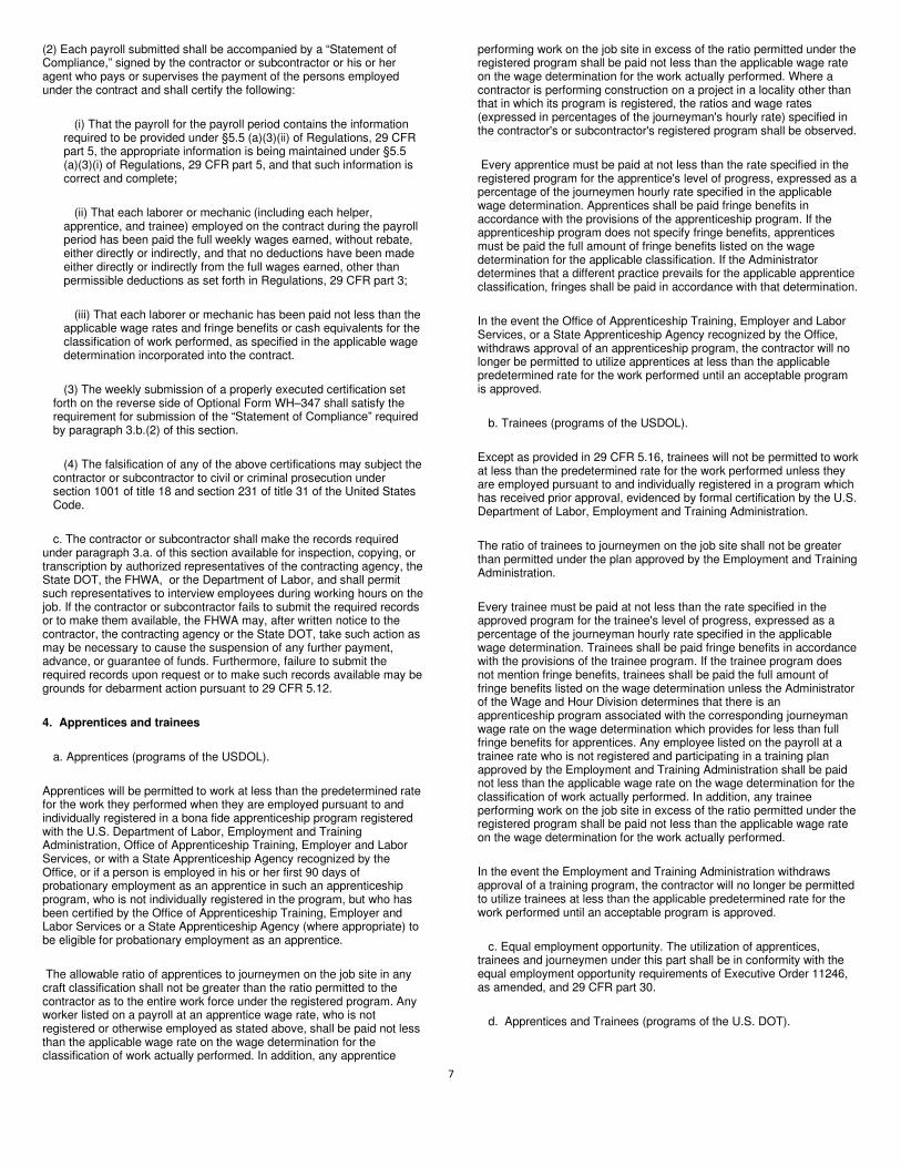
7
(2) Each payroll submitted shall be accompanied by a “Statement of Compliance,” signed by the contractor or subcontractor or his or her agent who pays or supervises the payment of the persons employed under the contract and shall certify the following:
(i) That the payroll for the payroll period contains the information required to be provided under §5.5 (a)(3)(ii) of Regulations, 29 CFR part 5, the appropriate information is being maintained under §5.5 (a)(3)(i) of Regulations, 29 CFR part 5, and that such information is correct and complete;
(ii) That each laborer or mechanic (including each helper, apprentice, and trainee) employed on the contract during the payroll period has been paid the full weekly wages earned, without rebate, either directly or indirectly, and that no deductions have been made either directly or indirectly from the full wages earned, other than permissible deductions as set forth in Regulations, 29 CFR part 3;
(iii) That each laborer or mechanic has been paid not less than the applicable wage rates and fringe benefits or cash equivalents for the classification of work performed, as specified in the applicable wage determination incorporated into the contract.
(3) The weekly submission of a properly executed certification set forth on the reverse side of Optional Form WH–347 shall satisfy the requirement for submission of the “Statement of Compliance” required by paragraph 3.b.(2) of this section.
(4) The falsification of any of the above certifications may subject the contractor or subcontractor to civil or criminal prosecution under section 1001 of title 18 and section 231 of title 31 of the United States Code.
c. The contractor or subcontractor shall make the records required under paragraph 3.a. of this section available for inspection, copying, or transcription by authorized representatives of the contracting agency, the State DOT, the FHWA, or the Department of Labor, and shall permit such representatives to interview employees during working hours on the job. If the contractor or subcontractor fails to submit the required records or to make them available, the FHWA may, after written notice to the contractor, the contracting agency or the State DOT, take such action as may be necessary to cause the suspension of any further payment, advance, or guarantee of funds. Furthermore, failure to submit the required records upon request or to make such records available may be grounds for debarment action pursuant to 29 CFR 5.12.
4. Apprentices and trainees
a. Apprentices (programs of the USDOL).
Apprentices will be permitted to work at less than the predetermined rate for the work they performed when they are employed pursuant to and individually registered in a bona fide apprenticeship program registered with the U.S. Department of Labor, Employment and Training Administration, Office of Apprenticeship Training, Employer and Labor Services, or with a State Apprenticeship Agency recognized by the Office, or if a person is employed in his or her first 90 days of probationary employment as an apprentice in such an apprenticeship program, who is not individually registered in the program, but who has been certified by the Office of Apprenticeship Training, Employer and Labor Services or a State Apprenticeship Agency (where appropriate) to be eligible for probationary employment as an apprentice.
The allowable ratio of apprentices to journeymen on the job site in any craft classification shall not be greater than the ratio permitted to the contractor as to the entire work force under the registered program. Any worker listed on a payroll at an apprentice wage rate, who is not registered or otherwise employed as stated above, shall be paid not less than the applicable wage rate on the wage determination for the classification of work actually performed. In addition, any apprentice
performing work on the job site in excess of the ratio permitted under the registered program shall be paid not less than the applicable wage rate on the wage determination for the work actually performed. Where a contractor is performing construction on a project in a locality other than that in which its program is registered, the ratios and wage rates (expressed in percentages of the journeyman's hourly rate) specified in the contractor's or subcontractor's registered program shall be observed.
Every apprentice must be paid at not less than the rate specified in the registered program for the apprentice's level of progress, expressed as a percentage of the journeymen hourly rate specified in the applicable wage determination. Apprentices shall be paid fringe benefits in accordance with the provisions of the apprenticeship program. If the apprenticeship program does not specify fringe benefits, apprentices must be paid the full amount of fringe benefits listed on the wage determination for the applicable classification. If the Administrator determines that a different practice prevails for the applicable apprentice classification, fringes shall be paid in accordance with that determination.
In the event the Office of Apprenticeship Training, Employer and Labor Services, or a State Apprenticeship Agency recognized by the Office, withdraws approval of an apprenticeship program, the contractor will no longer be permitted to utilize apprentices at less than the applicable predetermined rate for the work performed until an acceptable program is approved.
b. Trainees (programs of the USDOL).
Except as provided in 29 CFR 5.16, trainees will not be permitted to work at less than the predetermined rate for the work performed unless they are employed pursuant to and individually registered in a program which has received prior approval, evidenced by formal certification by the U.S. Department of Labor, Employment and Training Administration.
The ratio of trainees to journeymen on the job site shall not be greater than permitted under the plan approved by the Employment and Training Administration.
Every trainee must be paid at not less than the rate specified in the approved program for the trainee's level of progress, expressed as a percentage of the journeyman hourly rate specified in the applicable wage determination. Trainees shall be paid fringe benefits in accordance with the provisions of the trainee program. If the trainee program does not mention fringe benefits, trainees shall be paid the full amount of fringe benefits listed on the wage determination unless the Administrator of the Wage and Hour Division determines that there is an apprenticeship program associated with the corresponding journeyman wage rate on the wage determination which provides for less than full fringe benefits for apprentices. Any employee listed on the payroll at a trainee rate who is not registered and participating in a training plan approved by the Employment and Training Administration shall be paid not less than the applicable wage rate on the wage determination for the classification of work actually performed. In addition, any trainee performing work on the job site in excess of the ratio permitted under the registered program shall be paid not less than the applicable wage rate on the wage determination for the work actually performed.
In the event the Employment and Training Administration withdraws approval of a training program, the contractor will no longer be permitted to utilize trainees at less than the applicable predetermined rate for the work performed until an acceptable program is approved.
c. Equal employment opportunity. The utilization of apprentices, trainees and journeymen under this part shall be in conformity with the equal employment opportunity requirements of Executive Order 11246, as amended, and 29 CFR part 30.
d. Apprentices and Trainees (programs of the U.S. DOT).

8
Apprentices and trainees working under apprenticeship and skill training programs which have been certified by the Secretary of Transportation as promoting EEO in connection with Federal-aid highway construction programs are not subject to the requirements of paragraph 4 of this Section IV. The straight time hourly wage rates for apprentices and trainees under such programs will be established by the particular programs. The ratio of apprentices and trainees to journeymen shall not be greater than permitted by the terms of the particular program.
5. Compliance with Copeland Act requirements. The contractor shall comply with the requirements of 29 CFR part 3, which are incorporated by reference in this contract.
6. Subcontracts. The contractor or subcontractor shall insert Form FHWA-1273 in any subcontracts and also require the subcontractors to include Form FHWA-1273 in any lower tier subcontracts. The prime contractor shall be responsible for the compliance by any subcontractor or lower tier subcontractor with all the contract clauses in 29 CFR 5.5.
7. Contract termination: debarment. A breach of the contract clauses in 29 CFR 5.5 may be grounds for termination of the contract, and for debarment as a contractor and a subcontractor as provided in 29 CFR 5.12.
8. Compliance with Davis-Bacon and Related Act requirements. All rulings and interpretations of the Davis-Bacon and Related Acts contained in 29 CFR parts 1, 3, and 5 are herein incorporated by reference in this contract.
9. Disputes concerning labor standards. Disputes arising out of the labor standards provisions of this contract shall not be subject to the general disputes clause of this contract. Such disputes shall be resolved in accordance with the procedures of the Department of Labor set forth in 29 CFR parts 5, 6, and 7. Disputes within the meaning of this clause include disputes between the contractor (or any of its subcontractors) and the contracting agency, the U.S. Department of Labor, or the employees or their representatives.
10. Certification of eligibility.
a. By entering into this contract, the contractor certifies that neither it (nor he or she) nor any person or firm who has an interest in the contractor's firm is a person or firm ineligible to be awarded Government contracts by virtue of section 3(a) of the Davis-Bacon Act or 29 CFR 5.12(a)(1).
b. No part of this contract shall be subcontracted to any person or firm ineligible for award of a Government contract by virtue of section 3(a) of the Davis-Bacon Act or 29 CFR 5.12(a)(1).
c. The penalty for making false statements is prescribed in the U.S. Criminal Code, 18 U.S.C. 1001.
V. CONTRACT WORK HOURS AND SAFETY STANDARDS ACT
The following clauses apply to any Federal-aid construction contract in an amount in excess of $100,000 and subject to the overtime provisions of the Contract Work Hours and Safety Standards Act. These clauses shall be inserted in addition to the clauses required by 29 CFR 5.5(a) or 29 CFR 4.6. As used in this paragraph, the terms laborers and mechanics include watchmen and guards.
1. Overtime requirements. No contractor or subcontractor contracting for any part of the contract work which may require or involve the employment of laborers or mechanics shall require or permit any such laborer or mechanic in any workweek in which he or she is employed on such work to work in excess of forty hours in such workweek unless such laborer or mechanic receives compensation at a rate not less than one
and one-half times the basic rate of pay for all hours worked in excess of forty hours in such workweek.
2. Violation; liability for unpaid wages; liquidated damages. In the event of any violation of the clause set forth in paragraph (1.) of this section, the contractor and any subcontractor responsible therefor shall be liable for the unpaid wages. In addition, such contractor and subcontractor shall be liable to the United States (in the case of work done under contract for the District of Columbia or a territory, to such District or to such territory), for liquidated damages. Such liquidated damages shall be computed with respect to each individual laborer or mechanic, including watchmen and guards, employed in violation of the clause set forth in paragraph (1.) of this section, in the sum of $10 for each calendar day on which such individual was required or permitted to work in excess of the standard workweek of forty hours without payment of the overtime wages required by the clause set forth in paragraph (1.) of this section.
3. Withholding for unpaid wages and liquidated damages. The FHWA or the contacting agency shall upon its own action or upon written request of an authorized representative of the Department of Labor withhold or cause to be withheld, from any moneys payable on account of work performed by the contractor or subcontractor under any such contract or any other Federal contract with the same prime contractor, or any other federally-assisted contract subject to the Contract Work Hours and Safety Standards Act, which is held by the same prime contractor, such sums as may be determined to be necessary to satisfy any liabilities of such contractor or subcontractor for unpaid wages and liquidated damages as provided in the clause set forth in paragraph (2.) of this section.
4. Subcontracts. The contractor or subcontractor shall insert in any subcontracts the clauses set forth in paragraph (1.) through (4.) of this section and also a clause requiring the subcontractors to include these clauses in any lower tier subcontracts. The prime contractor shall be responsible for compliance by any subcontractor or lower tier subcontractor with the clauses set forth in paragraphs (1.) through (4.) of this section.
VI. SUBLETTING OR ASSIGNING THE CONTRACT This provision is applicable to all Federal-aid construction contracts on the National Highway System. 1. The contractor shall perform with its own organization contract work amounting to not less than 30 percent (or a greater percentage if specified elsewhere in the contract) of the total original contract price, excluding any specialty items designated by the contracting agency. Specialty items may be performed by subcontract and the amount of any such specialty items performed may be deducted from the total original contract price before computing the amount of work required to be performed by the contractor's own organization (23 CFR 635.116).
a. The term “perform work with its own organization” refers to workers employed or leased by the prime contractor, and equipment owned or rented by the prime contractor, with or without operators. Such term does not include employees or equipment of a subcontractor or lower tier subcontractor, agents of the prime contractor, or any other assignees. The term may include payments for the costs of hiring leased employees from an employee leasing firm meeting all relevant Federal and State regulatory requirements. Leased employees may only be included in this term if the prime contractor meets all of the following conditions: (1) the prime contractor maintains control over the supervision of the day-to-day activities of the leased employees;
(2) the prime contractor remains responsible for the quality of the work of the leased employees;
(3) the prime contractor retains all power to accept or exclude individual employees from work on the project; and

9
(4) the prime contractor remains ultimately responsible for the payment of predetermined minimum wages, the submission of payrolls, statements of compliance and all other Federal regulatory requirements.
b. "Specialty Items" shall be construed to be limited to work that
requires highly specialized knowledge, abilities, or equipment not ordinarily available in the type of contracting organizations qualified and expected to bid or propose on the contract as a whole and in general are to be limited to minor components of the overall contract. 2. The contract amount upon which the requirements set forth in paragraph (1) of Section VI is computed includes the cost of material and manufactured products which are to be purchased or produced by the contractor under the contract provisions. 3. The contractor shall furnish (a) a competent superintendent or supervisor who is employed by the firm, has full authority to direct performance of the work in accordance with the contract requirements, and is in charge of all construction operations (regardless of who performs the work) and (b) such other of its own organizational resources (supervision, management, and engineering services) as the contracting officer determines is necessary to assure the performance of the contract. 4. No portion of the contract shall be sublet, assigned or otherwise disposed of except with the written consent of the contracting officer, or authorized representative, and such consent when given shall not be construed to relieve the contractor of any responsibility for the fulfillment of the contract. Written consent will be given only after the contracting agency has assured that each subcontract is evidenced in writing and that it contains all pertinent provisions and requirements of the prime contract. 5. The 30% self-performance requirement of paragraph (1) is not applicable to design-build contracts; however, contracting agencies may establish their own self-performance requirements. VII. SAFETY: ACCIDENT PREVENTION This provision is applicable to all Federal-aid construction contracts and to all related subcontracts. 1. In the performance of this contract the contractor shall comply with all applicable Federal, State, and local laws governing safety, health, and sanitation (23 CFR 635). The contractor shall provide all safeguards, safety devices and protective equipment and take any other needed actions as it determines, or as the contracting officer may determine, to be reasonably necessary to protect the life and health of employees on the job and the safety of the public and to protect property in connection with the performance of the work covered by the contract. 2. It is a condition of this contract, and shall be made a condition of each subcontract, which the contractor enters into pursuant to this contract, that the contractor and any subcontractor shall not permit any employee, in performance of the contract, to work in surroundings or under conditions which are unsanitary, hazardous or dangerous to his/her health or safety, as determined under construction safety and health standards (29 CFR 1926) promulgated by the Secretary of Labor, in accordance with Section 107 of the Contract Work Hours and Safety Standards Act (40 U.S.C. 3704). 3. Pursuant to 29 CFR 1926.3, it is a condition of this contract that the Secretary of Labor or authorized representative thereof, shall have right of entry to any site of contract performance to inspect or investigate the matter of compliance with the construction safety and health standards and to carry out the duties of the Secretary under Section 107 of the Contract Work Hours and Safety Standards Act (40 U.S.C.3704). VIII. FALSE STATEMENTS CONCERNING HIGHWAY PROJECTS This provision is applicable to all Federal-aid construction contracts and to all related subcontracts.
In order to assure high quality and durable construction in conformity with approved plans and specifications and a high degree of reliability on statements and representations made by engineers, contractors, suppliers, and workers on Federal-aid highway projects, it is essential that all persons concerned with the project perform their functions as carefully, thoroughly, and honestly as possible. Willful falsification, distortion, or misrepresentation with respect to any facts related to the project is a violation of Federal law. To prevent any misunderstanding regarding the seriousness of these and similar acts, Form FHWA-1022 shall be posted on each Federal-aid highway project (23 CFR 635) in one or more places where it is readily available to all persons concerned with the project: 18 U.S.C. 1020 reads as follows: "Whoever, being an officer, agent, or employee of the United States, or of any State or Territory, or whoever, whether a person, association, firm, or corporation, knowingly makes any false statement, false representation, or false report as to the character, quality, quantity, or cost of the material used or to be used, or the quantity or quality of the work performed or to be performed, or the cost thereof in connection with the submission of plans, maps, specifications, contracts, or costs of construction on any highway or related project submitted for approval to the Secretary of Transportation; or Whoever knowingly makes any false statement, false representation, false report or false claim with respect to the character, quality, quantity, or cost of any work performed or to be performed, or materials furnished or to be furnished, in connection with the construction of any highway or related project approved by the Secretary of Transportation; or Whoever knowingly makes any false statement or false representation as to material fact in any statement, certificate, or report submitted pursuant to provisions of the Federal-aid Roads Act approved July 1, 1916, (39 Stat. 355), as amended and supplemented; Shall be fined under this title or imprisoned not more than 5 years or both." IX. IMPLEMENTATION OF CLEAN AIR ACT AND FEDERAL WATER POLLUTION CONTROL ACT This provision is applicable to all Federal-aid construction contracts and to all related subcontracts. By submission of this bid/proposal or the execution of this contract, or subcontract, as appropriate, the bidder, proposer, Federal-aid construction contractor, or subcontractor, as appropriate, will be deemed to have stipulated as follows: 1. That any person who is or will be utilized in the performance of this contract is not prohibited from receiving an award due to a violation of Section 508 of the Clean Water Act or Section 306 of the Clean Air Act. 2. That the contractor agrees to include or cause to be included the requirements of paragraph (1) of this Section X in every subcontract, and further agrees to take such action as the contracting agency may direct as a means of enforcing such requirements. X. CERTIFICATION REGARDING DEBARMENT, SUSPENSION, INELIGIBILITY AND VOLUNTARY EXCLUSION This provision is applicable to all Federal-aid construction contracts, design-build contracts, subcontracts, lower-tier subcontracts, purchase orders, lease agreements, consultant contracts or any other covered transaction requiring FHWA approval or that is estimated to cost $25,000 or more – as defined in 2 CFR Parts 180 and 1200. 1. Instructions for Certification – First Tier Participants:

10
a. By signing and submitting this proposal, the prospective first tier participant is providing the certification set out below. b. The inability of a person to provide the certification set out below will not necessarily result in denial of participation in this covered transaction. The prospective first tier participant shall submit an explanation of why it cannot provide the certification set out below. The certification or explanation will be considered in connection with the department or agency's determination whether to enter into this transaction. However, failure of the prospective first tier participant to furnish a certification or an explanation shall disqualify such a person from participation in this transaction. c. The certification in this clause is a material representation of fact upon which reliance was placed when the contracting agency determined to enter into this transaction. If it is later determined that the prospective participant knowingly rendered an erroneous certification, in addition to other remedies available to the Federal Government, the contracting agency may terminate this transaction for cause of default. d. The prospective first tier participant shall provide immediate written notice to the contracting agency to whom this proposal is submitted if any time the prospective first tier participant learns that its certification was erroneous when submitted or has become erroneous by reason of changed circumstances. e. The terms "covered transaction," "debarred," "suspended," "ineligible," "participant," "person," "principal," and "voluntarily excluded," as used in this clause, are defined in 2 CFR Parts 180 and 1200. “First Tier Covered Transactions” refers to any covered transaction between a grantee or subgrantee of Federal funds and a participant (such as the prime or general contract). “Lower Tier Covered Transactions” refers to any covered transaction under a First Tier Covered Transaction (such as subcontracts). “First Tier Participant” refers to the participant who has entered into a covered transaction with a grantee or subgrantee of Federal funds (such as the prime or general contractor). “Lower Tier Participant” refers any participant who has entered into a covered transaction with a First Tier Participant or other Lower Tier Participants (such as subcontractors and suppliers). f. The prospective first tier participant agrees by submitting this proposal that, should the proposed covered transaction be entered into, it shall not knowingly enter into any lower tier covered transaction with a person who is debarred, suspended, declared ineligible, or voluntarily excluded from participation in this covered transaction, unless authorized by the department or agency entering into this transaction. g. The prospective first tier participant further agrees by submitting this proposal that it will include the clause titled "Certification Regarding Debarment, Suspension, Ineligibility and Voluntary Exclusion-Lower Tier Covered Transactions," provided by the department or contracting agency, entering into this covered transaction, without modification, in all lower tier covered transactions and in all solicitations for lower tier covered transactions exceeding the $25,000 threshold. h. A participant in a covered transaction may rely upon a certification of a prospective participant in a lower tier covered transaction that is not debarred, suspended, ineligible, or voluntarily excluded from the covered transaction, unless it knows that the certification is erroneous. A participant is responsible for ensuring that its principals are not suspended, debarred, or otherwise ineligible to participate in covered transactions. To verify the eligibility of its principals, as well as the eligibility of any lower tier prospective participants, each participant may, but is not required to, check the Excluded Parties List System website (https://www.epls.gov/), which is compiled by the General Services Administration. i. Nothing contained in the foregoing shall be construed to require the establishment of a system of records in order to render in good faith the certification required by this clause. The knowledge and information of the prospective participant is not required to exceed that which is normally possessed by a prudent person in the ordinary course of business dealings.
j. Except for transactions authorized under paragraph (f) of these instructions, if a participant in a covered transaction knowingly enters into a lower tier covered transaction with a person who is suspended, debarred, ineligible, or voluntarily excluded from participation in this transaction, in addition to other remedies available to the Federal Government, the department or agency may terminate this transaction for cause or default. * * * * * 2. Certification Regarding Debarment, Suspension, Ineligibility and Voluntary Exclusion – First Tier Participants: a. The prospective first tier participant certifies to the best of its knowledge and belief, that it and its principals: (1) Are not presently debarred, suspended, proposed for debarment, declared ineligible, or voluntarily excluded from participating in covered transactions by any Federal department or agency; (2) Have not within a three-year period preceding this proposal been convicted of or had a civil judgment rendered against them for commission of fraud or a criminal offense in connection with obtaining, attempting to obtain, or performing a public (Federal, State or local) transaction or contract under a public transaction; violation of Federal or State antitrust statutes or commission of embezzlement, theft, forgery, bribery, falsification or destruction of records, making false statements, or receiving stolen property; (3) Are not presently indicted for or otherwise criminally or civilly charged by a governmental entity (Federal, State or local) with commission of any of the offenses enumerated in paragraph (a)(2) of this certification; and (4) Have not within a three-year period preceding this application/proposal had one or more public transactions (Federal, State or local) terminated for cause or default. b. Where the prospective participant is unable to certify to any of the statements in this certification, such prospective participant shall attach an explanation to this proposal. 2. Instructions for Certification - Lower Tier Participants: (Applicable to all subcontracts, purchase orders and other lower tier transactions requiring prior FHWA approval or estimated to cost $25,000 or more - 2 CFR Parts 180 and 1200) a. By signing and submitting this proposal, the prospective lower tier is providing the certification set out below. b. The certification in this clause is a material representation of fact upon which reliance was placed when this transaction was entered into. If it is later determined that the prospective lower tier participant knowingly rendered an erroneous certification, in addition to other remedies available to the Federal Government, the department, or agency with which this transaction originated may pursue available remedies, including suspension and/or debarment. c. The prospective lower tier participant shall provide immediate written notice to the person to which this proposal is submitted if at any time the prospective lower tier participant learns that its certification was erroneous by reason of changed circumstances. d. The terms "covered transaction," "debarred," "suspended," "ineligible," "participant," "person," "principal," and "voluntarily excluded," as used in this clause, are defined in 2 CFR Parts 180 and 1200. You may contact the person to which this proposal is submitted for assistance in obtaining a copy of those regulations. “First Tier Covered Transactions” refers to any covered transaction between a grantee or subgrantee of Federal funds and a participant (such as the prime or general contract). “Lower Tier Covered Transactions” refers to any covered transaction under a First Tier Covered Transaction (such as subcontracts). “First Tier Participant” refers to the participant who has entered into a covered transaction with a grantee or subgrantee of

11
Federal funds (such as the prime or general contractor). “Lower Tier Participant” refers any participant who has entered into a covered transaction with a First Tier Participant or other Lower Tier Participants (such as subcontractors and suppliers). e. The prospective lower tier participant agrees by submitting this proposal that, should the proposed covered transaction be entered into, it shall not knowingly enter into any lower tier covered transaction with a person who is debarred, suspended, declared ineligible, or voluntarily excluded from participation in this covered transaction, unless authorized by the department or agency with which this transaction originated. f. The prospective lower tier participant further agrees by submitting this proposal that it will include this clause titled "Certification Regarding Debarment, Suspension, Ineligibility and Voluntary Exclusion-Lower Tier Covered Transaction," without modification, in all lower tier covered transactions and in all solicitations for lower tier covered transactions exceeding the $25,000 threshold. g. A participant in a covered transaction may rely upon a certification of a prospective participant in a lower tier covered transaction that is not debarred, suspended, ineligible, or voluntarily excluded from the covered transaction, unless it knows that the certification is erroneous. A participant is responsible for ensuring that its principals are not suspended, debarred, or otherwise ineligible to participate in covered transactions. To verify the eligibility of its principals, as well as the eligibility of any lower tier prospective participants, each participant may, but is not required to, check the Excluded Parties List System website (https://www.epls.gov/), which is compiled by the General Services Administration. h. Nothing contained in the foregoing shall be construed to require establishment of a system of records in order to render in good faith the certification required by this clause. The knowledge and information of participant is not required to exceed that which is normally possessed by a prudent person in the ordinary course of business dealings. i. Except for transactions authorized under paragraph e of these instructions, if a participant in a covered transaction knowingly enters into a lower tier covered transaction with a person who is suspended, debarred, ineligible, or voluntarily excluded from participation in this transaction, in addition to other remedies available to the Federal Government, the department or agency with which this transaction originated may pursue available remedies, including suspension and/or debarment. * * * * * Certification Regarding Debarment, Suspension, Ineligibility and Voluntary Exclusion--Lower Tier Participants: 1. The prospective lower tier participant certifies, by submission of this proposal, that neither it nor its principals is presently debarred, suspended, proposed for debarment, declared ineligible, or voluntarily excluded from participating in covered transactions by any Federal department or agency. 2. Where the prospective lower tier participant is unable to certify to any of the statements in this certification, such prospective participant shall attach an explanation to this proposal. * * * * * XI. CERTIFICATION REGARDING USE OF CONTRACT FUNDS FOR LOBBYING This provision is applicable to all Federal-aid construction contracts and to all related subcontracts which exceed $100,000 (49 CFR 20). 1. The prospective participant certifies, by signing and submitting this bid or proposal, to the best of his or her knowledge and belief, that: a. No Federal appropriated funds have been paid or will be paid, by or on behalf of the undersigned, to any person for influencing or attempting to influence an officer or employee of any Federal agency, a Member of
Congress, an officer or employee of Congress, or an employee of a Member of Congress in connection with the awarding of any Federal contract, the making of any Federal grant, the making of any Federal loan, the entering into of any cooperative agreement, and the extension, continuation, renewal, amendment, or modification of any Federal contract, grant, loan, or cooperative agreement. b. If any funds other than Federal appropriated funds have been paid or will be paid to any person for influencing or attempting to influence an officer or employee of any Federal agency, a Member of Congress, an officer or employee of Congress, or an employee of a Member of Congress in connection with this Federal contract, grant, loan, or cooperative agreement, the undersigned shall complete and submit Standard Form-LLL, "Disclosure Form to Report Lobbying," in accordance with its instructions. 2. This certification is a material representation of fact upon which reliance was placed when this transaction was made or entered into. Submission of this certification is a prerequisite for making or entering into this transaction imposed by 31 U.S.C. 1352. Any person who fails to file the required certification shall be subject to a civil penalty of not less than $10,000 and not more than $100,000 for each such failure. 3. The prospective participant also agrees by submitting its bid or proposal that the participant shall require that the language of this certification be included in all lower tier subcontracts, which exceed $100,000 and that all such recipients shall certify and disclose accordingly.

12
ATTACHMENT A - EMPLOYMENT AND MATERIALS PREFERENCE FOR APPALACHIAN DEVELOPMENT HIGHWAY SYSTEM OR APPALACHIAN LOCAL ACCESS ROAD CONTRACTS This provision is applicable to all Federal-aid projects funded under the Appalachian Regional Development Act of 1965. 1. During the performance of this contract, the contractor undertaking to do work which is, or reasonably may be, done as on-site work, shall give preference to qualified persons who regularly reside in the labor area as designated by the DOL wherein the contract work is situated, or the subregion, or the Appalachian counties of the State wherein the contract work is situated, except: a. To the extent that qualified persons regularly residing in the area are not available. b. For the reasonable needs of the contractor to employ supervisory or specially experienced personnel necessary to assure an efficient execution of the contract work. c. For the obligation of the contractor to offer employment to present or former employees as the result of a lawful collective bargaining contract, provided that the number of nonresident persons employed under this subparagraph (1c) shall not exceed 20 percent of the total number of employees employed by the contractor on the contract work, except as provided in subparagraph (4) below. 2. The contractor shall place a job order with the State Employment Service indicating (a) the classifications of the laborers, mechanics and other employees required to perform the contract work, (b) the number of employees required in each classification, (c) the date on which the participant estimates such employees will be required, and (d) any other pertinent information required by the State Employment Service to complete the job order form. The job order may be placed with the State Employment Service in writing or by telephone. If during the course of the contract work, the information submitted by the contractor in the original job order is substantially modified, the participant shall promptly notify the State Employment Service. 3. The contractor shall give full consideration to all qualified job applicants referred to him by the State Employment Service. The contractor is not required to grant employment to any job applicants who, in his opinion, are not qualified to perform the classification of work required. 4. If, within one week following the placing of a job order by the contractor with the State Employment Service, the State Employment Service is unable to refer any qualified job applicants to the contractor, or less than the number requested, the State Employment Service will forward a certificate to the contractor indicating the unavailability of applicants. Such certificate shall be made a part of the contractor's permanent project records. Upon receipt of this certificate, the contractor may employ persons who do not normally reside in the labor area to fill positions covered by the certificate, notwithstanding the provisions of subparagraph (1c) above. 5. The provisions of 23 CFR 633.207(e) allow the contracting agency to provide a contractual preference for the use of mineral resource materials native to the Appalachian region. 6. The contractor shall include the provisions of Sections 1 through 4 of this Attachment A in every subcontract for work which is, or reasonably may be, done as on-site work.

13
Contract Provision - Cargo Preference Requirements
In accordance with Title 46 CFR § 381.7 (b), the contractor agrees—
“(1) To utilize privately owned United States-flag commercial vessels to ship at least 50 percent of the gross tonnage
(computed separately for dry bulk carriers, dry cargo liners, and tankers) involved, whenever shipping any equipment,
material, or commodities pursuant to this contract, to the extent such vessels are available at fair and reasonable rates for
United States-flag commercial vessels.
(2) To furnish within 20 days following the date of loading for shipments originating within the United States or within 30
working days following the date of loading for shipments originating outside the United States, a legible copy of a rated,
‘on-board’ commercial ocean bill-of-lading in English for each shipment of cargo described in paragraph (b) (1) of this
section to both the Contracting Officer (through the prime contractor in the case of subcontractor bills-of-lading) and to the
Division of National Cargo, Office of Market Development, Maritime Administration, Washington, DC 20590.
(3) To insert the substance of the provisions of this clause in all subcontracts issued pursuant to this contract.”
Provisions (1) and (2) apply to materials or equipment that are acquired solely for the project. The two provisions do not
apply to goods or materials that come into inventories independent of the project, such as shipments of Portland
cement, asphalt cement, or aggregates, when industry suppliers and contractors use these materials to replenish
existing inventories.

14
MINIMUM WAGES FOR FEDERAL AND FEDERALLY
ASSISTED CONSTRUCTION CONTRACTS
This project is funded, in part, with Federal-aid funds and, as such, is subject to the provisions of the Davis-Bacon Act of March 3, 1931, as
amended (46 Sta. 1494, as amended, 40 U.S.C. 276a) and of other Federal statutes referred to in a 29 CFR Part 1, Appendix A, as well as such
additional statutes as may from time to time be enacted containing provisions for the payment of wages determined to be prevailing by the
Secretary of Labor in accordance with the Davis-Bacon Act and pursuant to the provisions of 29 CFR Part 1. The prevailing rates and fringe
benefits shown in the General Wage Determination Decisions issued by the U.S. Department of Labor shall, in accordance with the provisions
of the foregoing statutes, constitute the minimum wages payable on Federal and federally assisted construction projects to laborers and
mechanics of the specified classes engaged on contract work of the character and in the localities described therein.
General Wage Determination Decisions, modifications and supersedes decisions thereto are to be used in accordance with the provisions of 29
CFR Parts 1 and 5. Accordingly, the applicable decision, together with any modifications issued, must be made a part of every contract for
performance of the described work within the geographic area indicated as required by an applicable DBRA Federal prevailing wage law and 29
CFR Part 5. The wage rates and fringe benefits contained in the General Wage Determination Decision shall be the minimum paid by contractors
and subcontractors to laborers and mechanics.