Embed Size (px)
Citation preview
Copyright © Winters2 2004Version 1.0
Lesson 9: Base Stations
Preparation for Amateur Radio
Technician Class Exam
Copyright © Winters2 2004Version 1.0
Lesson 2: How Radio Works - 1
TopicsHome StationsBasic Station LayoutRTTY and Data CommunicationsStation AccessoriesWavelengthsFeed LinesImpedance-matching & balancingExam Questions for this section
Copyright © Winters2 2004Version 1.0
Lesson 2: How Radio Works - 2
ReadingChapter 8 – 8.1-8.19
Copyright © Winters2 2004Version 1.0
Lesson 2: How Radio Works - 3
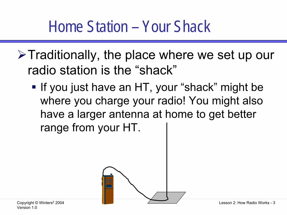
Home Station – Your ShackTraditionally, the place where we set up our radio station is the “shack”
If you just have an HT, your “shack” might be where you charge your radio! You might also have a larger antenna at home to get better range from your HT.
Copyright © Winters2 2004Version 1.0
Lesson 2: How Radio Works - 4
Home Station – Your ShackYour shack should enable you to lock up your gear to prevent unlicensed people from using it when you are not present
Many hams have their HTs with them at all times, so don’t have to worry about locking them!If your shack is in an area where the radio sounds might bother others, you can get a headset with microphone to use with your radio
Copyright © Winters2 2004Version 1.0
Lesson 2: How Radio Works - 5
Base Station LayoutAny ham radio operator with any license can build and operate their own radio station. In this section we look at the parts of a station that you need to operate
Most of these components are built into your HT radios
Copyright © Winters2 2004Version 1.0
Lesson 2: How Radio Works - 6
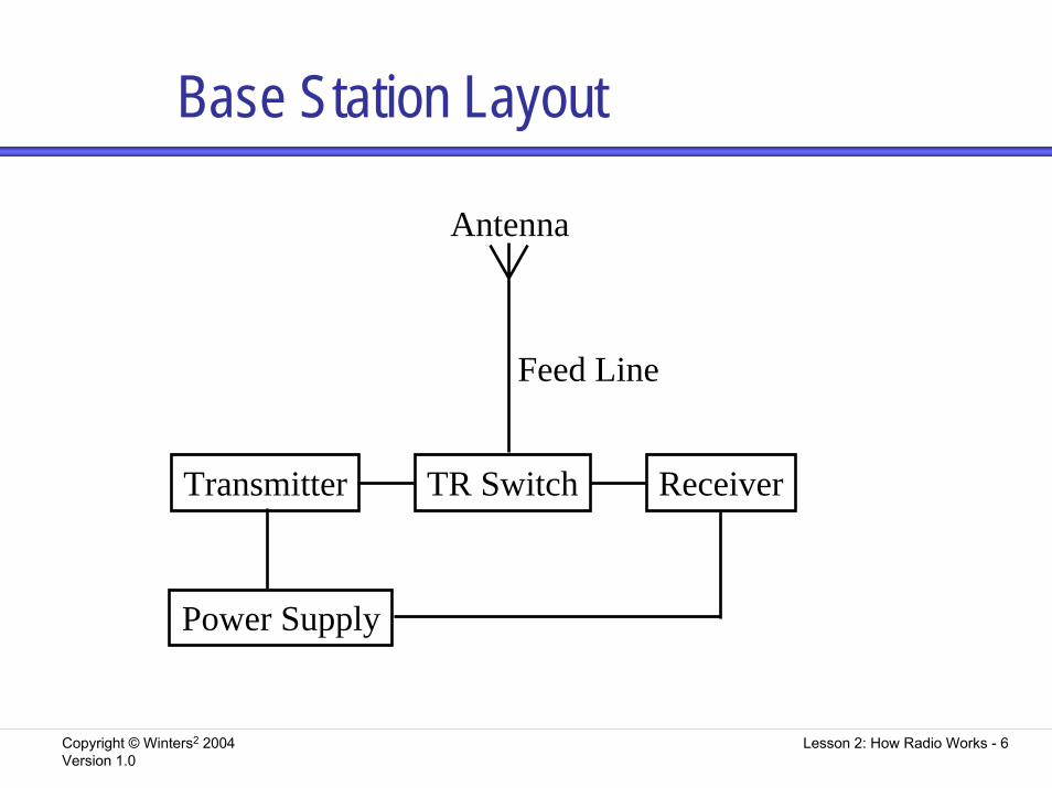
Base Station Layout
Transmitter TR Switch Receiver
Power Supply
Feed Line
Antenna
Copyright © Winters2 2004Version 1.0
Lesson 2: How Radio Works - 7
TransmittersA transmitter produces RF signalsThe signal from a transmitter is called an RF carrierTransmitters have two stages:
OscillatorPower amplifier
Copyright © Winters2 2004Version 1.0
Lesson 2: How Radio Works - 8
Transmitters - CWTo transmit Morse Code the RF signal from a transmitter is turned on and off in a pattern
This is a kind of modulation of the RF signalThe frequency you transmit on can be set in two different ways
Crystal oscillatorVariable-frequency oscillator (VFO)
To prevent AC hum from interfering by modulating the CW transmission, be sure the power supply is filtered
Copyright © Winters2 2004Version 1.0
Lesson 2: How Radio Works - 9
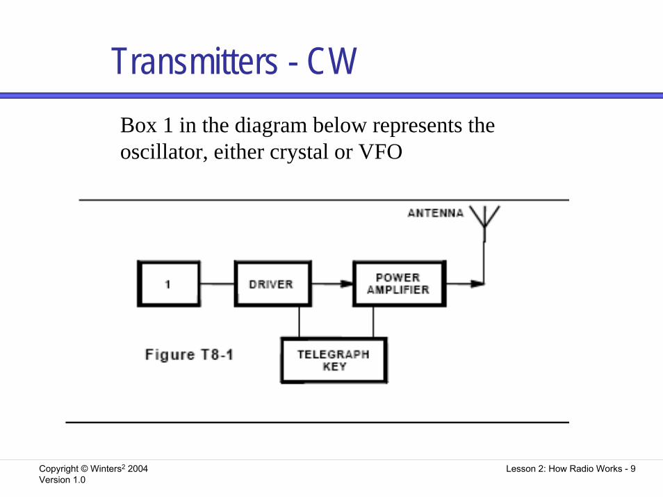
Transmitters - CWBox 1 in the diagram below represents the oscillator, either crystal or VFO
Copyright © Winters2 2004Version 1.0
Lesson 2: How Radio Works - 10
Transmitters - FMTo transmit voice, the RF signal from a transmitter is modified when a circuit called a modulator is used to add voice content to the RF carrierFM transmission is popular because it is less affected by interference from static-type electrical noise than the AM modesThe signal can be modulated by either frequency or phase
These are so closely related, that practically they will appear to be the same – only the circuitry varies
Copyright © Winters2 2004Version 1.0
Lesson 2: How Radio Works - 11
Transmitters - FMThe frequency from the oscillator is modulated by a circuit called a reactance modulator, which reacts to the rise and fall of your voice to raise and lower the frequency that is transmitted
Copyright © Winters2 2004Version 1.0
Lesson 2: How Radio Works - 12
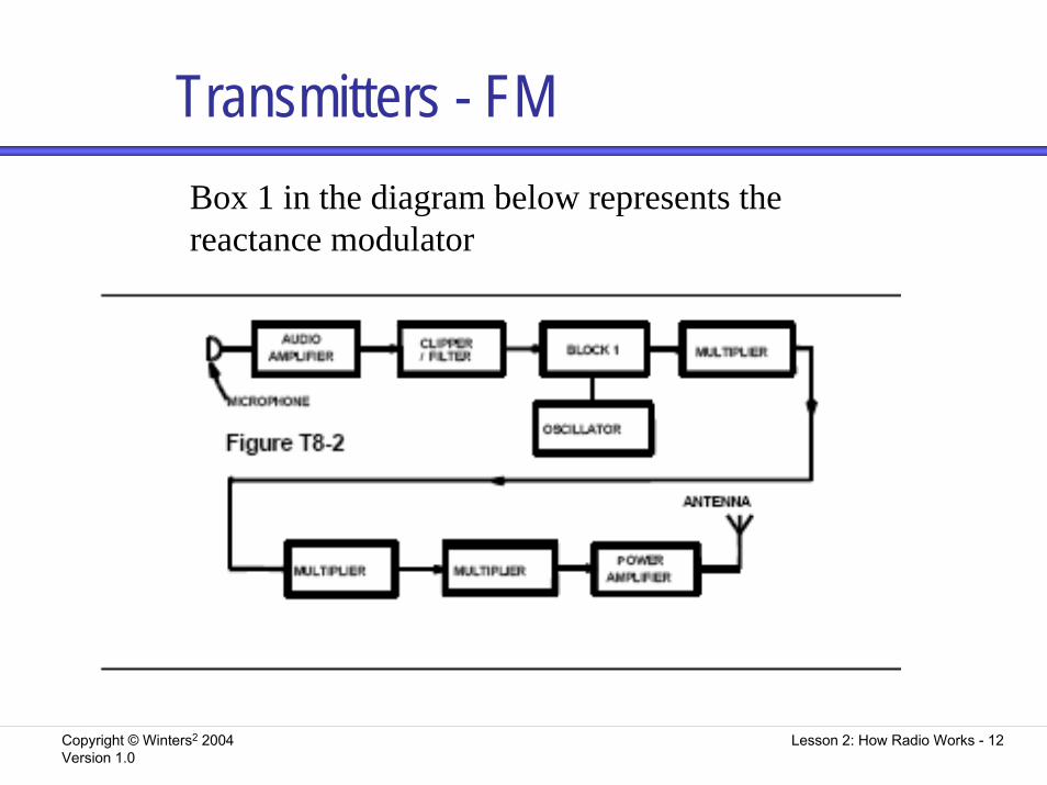
Transmitters - FMBox 1 in the diagram below represents the reactance modulator
Copyright © Winters2 2004Version 1.0
Lesson 2: How Radio Works - 13
Transmitters - FMThe voice signal from the microphone is rather weak, so it is boosted by the audio amplifier
If the audio amplifier isn’t working, the signal from the microphone will be too weak to modulate the signal
The clipper/filter sets the amplitude of the signalIf the clipper/filter is not doing its job correctly, the signal can be over deviated and interfere with transmissions on nearby channelsIf someone tells you that your radio is over-deviating, try talking software or holding the microphone further away
Copyright © Winters2 2004Version 1.0
Lesson 2: How Radio Works - 14
ReceiversA receiver converts RF energy into an audio-frequency signalThe heart of the receiver is the detector
A detector compares an unmodulated model to an incoming signal to get informationDetectors are particular to types of modulation, such as AM, FM, or phase
Copyright © Winters2 2004Version 1.0
Lesson 2: How Radio Works - 15
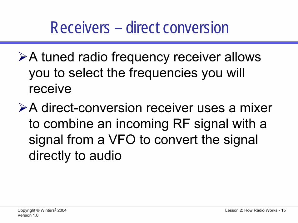
Receivers – direct conversionA tuned radio frequency receiver allows you to select the frequencies you will receiveA direct-conversion receiver uses a mixer to combine an incoming RF signal with a signal from a VFO to convert the signal directly to audio
Copyright © Winters2 2004Version 1.0
Lesson 2: How Radio Works - 16
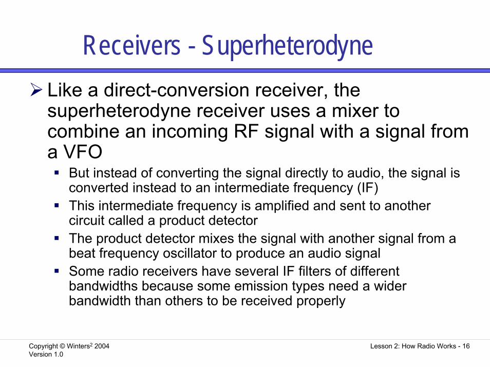
Receivers - SuperheterodyneLike a direct-conversion receiver, the superheterodyne receiver uses a mixer to combine an incoming RF signal with a signal from a VFO
But instead of converting the signal directly to audio, the signal is converted instead to an intermediate frequency (IF)This intermediate frequency is amplified and sent to another circuit called a product detectorThe product detector mixes the signal with another signal from abeat frequency oscillator to produce an audio signalSome radio receivers have several IF filters of different bandwidths because some emission types need a wider bandwidth than others to be received properly
Copyright © Winters2 2004Version 1.0
Lesson 2: How Radio Works - 17
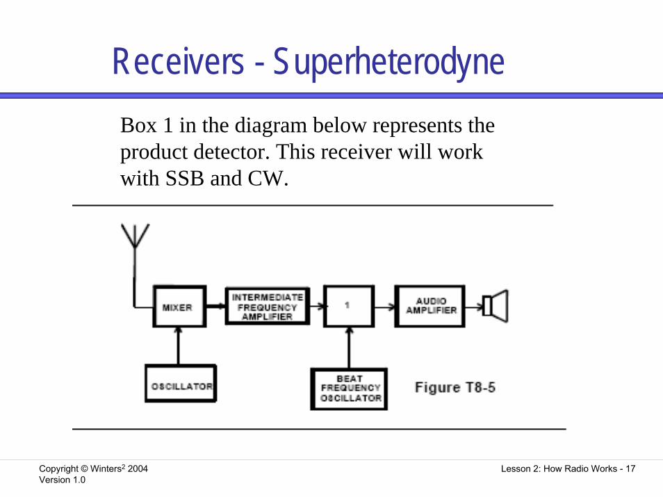
Receivers - SuperheterodyneBox 1 in the diagram below represents the product detector. This receiver will work with SSB and CW.
Copyright © Winters2 2004Version 1.0
Lesson 2: How Radio Works - 18
Receivers - SuperheterodyneTo avoid the incoming sound from getting too loud and hurting your ears, most commercial receivers include automatic gain controlYou can use an S meter connected across the automatic gain control line to show relative signal strengthTo determine if your radio is properly calibrated for frequency, you can tune it in to the NIST frequency standard stations WWV or WWVH
Copyright © Winters2 2004Version 1.0
Lesson 2: How Radio Works - 19
Receivers - FMAn FM superheterodyne repeater adds more stages
It has a different kind of detector called a frequency discriminator
• With no frequency discriminator, you will have no audio output
It also will usually include squelch circuitry• This mutes the noise when an FM carrier signal is
not present• Tune the squelch just until noise is silenced, but you
can still hear transmissions
Copyright © Winters2 2004Version 1.0
Lesson 2: How Radio Works - 20
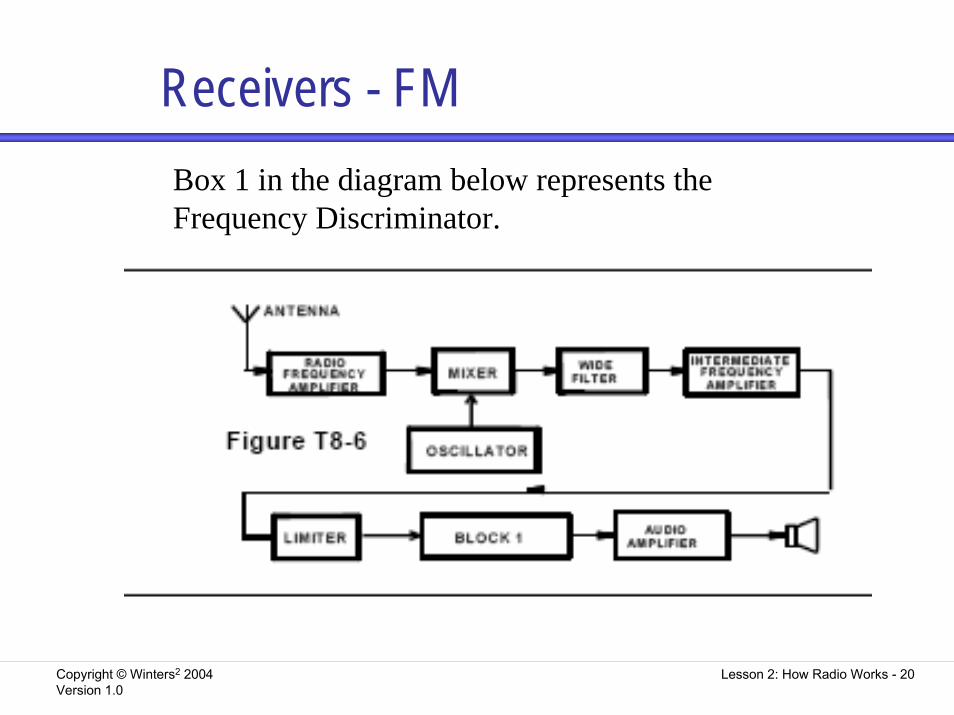
Receivers - FMBox 1 in the diagram below represents the Frequency Discriminator.
Copyright © Winters2 2004Version 1.0
Lesson 2: How Radio Works - 21
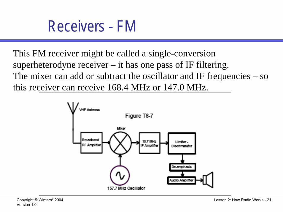
Receivers - FMThis FM receiver might be called a single-conversion superheterodyne receiver – it has one pass of IF filtering.The mixer can add or subtract the oscillator and IF frequencies – so this receiver can receive 168.4 MHz or 147.0 MHz.
Copyright © Winters2 2004Version 1.0
Lesson 2: How Radio Works - 22
TransceiversA transceiver is a transmitter and a receiver put together in one boxA mobile transceiver is typically used in the car and is designed to run on 12V DC
To use it at home either connect it to a 12V battery, or connect it to a power supply that converts 120V AC to 12V DC
Copyright © Winters2 2004Version 1.0
Lesson 2: How Radio Works - 23
Trouble-shootingYour radio works fine in the car but not in the house:
Check the power supply• Connect a voltmeter at the 12 V plug on the chassis
of the radio when transmitting to see what current it is drawing
• If there is no voltage, check the fuses
You hear a whine or clicks when running the radio using DC
Filter the power lines for DC as well as RF
Copyright © Winters2 2004Version 1.0
Lesson 2: How Radio Works - 24
RTTY & Data CommunicationsThese are forms of digital communications, often involving direct transfer of information between computers
Copyright © Winters2 2004Version 1.0
Lesson 2: How Radio Works - 25
RTTYRadioteletype
You connect the transceiver to a modem that is connected to either a computer or teleprinterData received through the transceiver is output on the teleprinter or computerIn the VHF/UHF bands, a common method of transmitting RTTY is to modulate a conventional FM transmitter with a modem
Copyright © Winters2 2004Version 1.0
Lesson 2: How Radio Works - 26
PacketPacket uses a terminal node controller (TNC) in place of a modem
The sending TNC breaks the data into chunks, called packets, to send information to another TNCA receiving TNC recombines the packets into a signal
The transceiver is often a VHF or UHF FM transceiver with the squelch control set low enough to receive packets, but high enough to filter out noise that might be mistaken for data
Copyright © Winters2 2004Version 1.0
Lesson 2: How Radio Works - 27
Station AccessoriesAntenna SwitchSWR MeterAntenna TunerTelegraph Key (paddle or bug)MicrophoneDuplexerPower amplifier
Copyright © Winters2 2004Version 1.0
Lesson 2: How Radio Works - 28
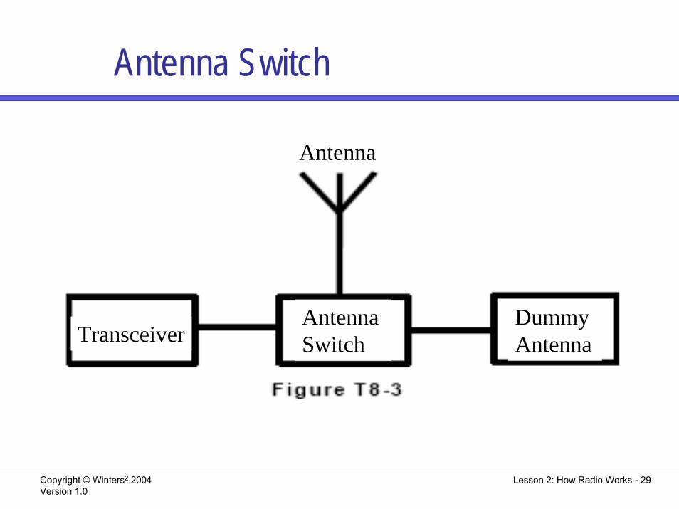
Antenna SwitchThis connects one transceiver (or transmitter/receiver pair) to several antennasThe switch determines which antenna the radio is currently usingMany hams have a switch between an antenna and a dummy antenna
Copyright © Winters2 2004Version 1.0
Lesson 2: How Radio Works - 29
Antenna Switch
TransceiverAntenna Switch
Antenna
Dummy Antenna
Copyright © Winters2 2004Version 1.0
Lesson 2: How Radio Works - 30
SWR MeterThis measures the standing-wave ratioSWR indicates how well your antenna system is workingConnect between the antenna switch and the transceiver, as close to the transmitter output as possible
Copyright © Winters2 2004Version 1.0
Lesson 2: How Radio Works - 31
Antenna TunerAn antenna matches the impedance of the load (antenna and feed line) to the impedance of the transmitter
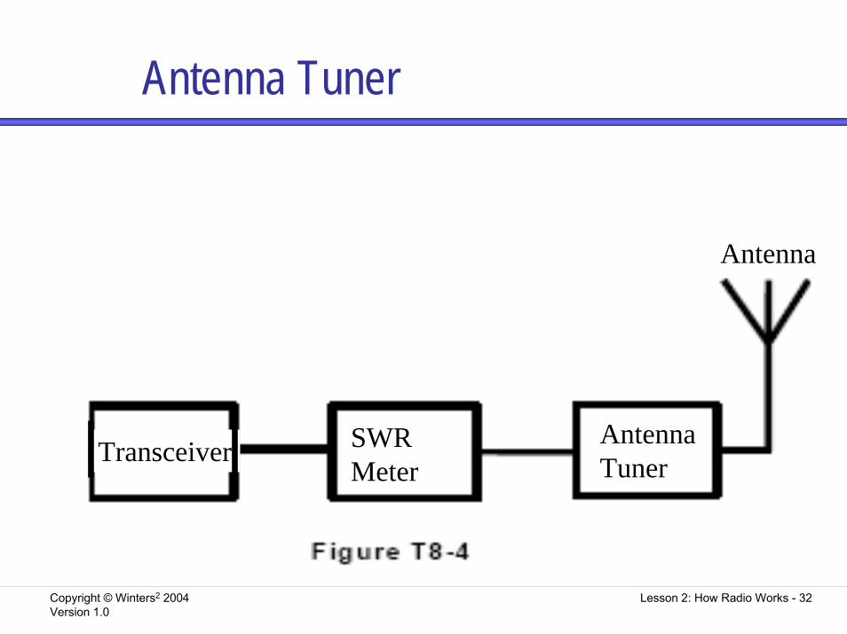
It lets you use the same antenna on several bands, or use an antenna on a band it is not designed forConnect the antenna tuner right where the antenna comes into the stationConnect the SWR meter between the antenna tuner and the transceiver when tuning the system
Copyright © Winters2 2004Version 1.0
Lesson 2: How Radio Works - 32
Antenna Tuner
Transceiver Antenna Tuner
Antenna
SWRMeter
Copyright © Winters2 2004Version 1.0
Lesson 2: How Radio Works - 33
Telegraph KeyThis is a device to send Morse Code
It is also called a straight key or bugAn electronic keyer is another device to send Morse Code
It is connected to a paddle It sends dots when you press one side of the paddle and dashes one you press the other side
Connects directly to the transmitter
Copyright © Winters2 2004Version 1.0
Lesson 2: How Radio Works - 34
MicrophoneUsed to transmit voice signalsConnects directly to the transmitter
Copyright © Winters2 2004Version 1.0
Lesson 2: How Radio Works - 35
DuplexerPopular HTs and mobile radios are dual-band or multi-mode
A popular combination of frequencies for dual-band radios is 2 meter and 70 cmA multi-mode VHF transceiver could be used for weak-signal VHF communication, or to combine FM phone with weak-signal SSB
A duplexer in the radio makes sure that the signal on one frequency goes out to the antenna and is not received on the other frequency
Similarly it automatically switches the signal received from the antenna to the correct receiver
Copyright © Winters2 2004Version 1.0
Lesson 2: How Radio Works - 36
Power AmplifierAn external power amplifier can be used to boost the power output of your radio
These are popular with hams who have low power HT radios that they want to use at home with an outside antenna
Copyright © Winters2 2004Version 1.0
Lesson 2: How Radio Works - 37
Feed LinesA feed line transfers the RF signal from your antenna to your receiver, or from your transmitter to your antennaThe impedance of the feed line should match the impedance of the transceiver and the antennaTypes of feed line include:
Coaxial cable or coaxOpen-wire line or parallel-conductor feed line
Copyright © Winters2 2004Version 1.0
Lesson 2: How Radio Works - 38
CoaxHas one center wire, inside insulation, inside a metal sleeveTypically has a 50Ω or 75Ω impedance
RG-58, RG-8 and RG-213 are 50Ω cablesRG-59 and RG-11 are 75Ω cables
A half wavelength dipole far from other objects has a 73Ω impedanceThe same antenna near the ground, trees, or buildings has a 50Ω impedanceRG-58 and RG-59 cables are thinner in diameter than the others, but have a higher signal loss and handle lower power
Copyright © Winters2 2004Version 1.0
Lesson 2: How Radio Works - 39
Open-wire transmission linesTwo parallel wires spaced a constant distance by an insulator
Also called parallel-conductor feed lineLess signal loss than coaxOperates well with a high SWRCheaper than coaxBalanced transmission line
An unbalanced transmission line has a conductor connected to ground (Coax is unbalanced)
Copyright © Winters2 2004Version 1.0
Lesson 2: How Radio Works - 40
SWRPower traveling from the transmitter to the antenna is forward powerIn a system where there is an impedance mismatch between the transmitter and antenna, power can be reflected from the antenna back to the transmitter. This is reflected power.The ratio of the maximum voltage to the minimum voltage on the line is the standing-wave ratio (SWR)
Copyright © Winters2 2004Version 1.0
Lesson 2: How Radio Works - 41
SWR MeterAn SWR meter is used to measure SWRWhen the SWR is 1:1, the impedances of the antenna and transmission line match
This would be great, but no system is perfect!An SWR of 1.5:1 is actually very good, and 2:1 is quite acceptable
An SWR of 4:1 indicates a serious mismatch of impedancesMeasure SWR at the antenna feed point, the place where the feed line connects to the antenna
Copyright © Winters2 2004Version 1.0
Lesson 2: How Radio Works - 42
WattmeterA wattmeter measures power in watts
Wattmeters usually operate at 50ΩYou can use a wattmeter to determine the true forward power in your systemMeasure the forward power and the reflected power and use this formula
True forward power = forward power– reflected power
Copyright © Winters2 2004Version 1.0
Lesson 2: How Radio Works - 43
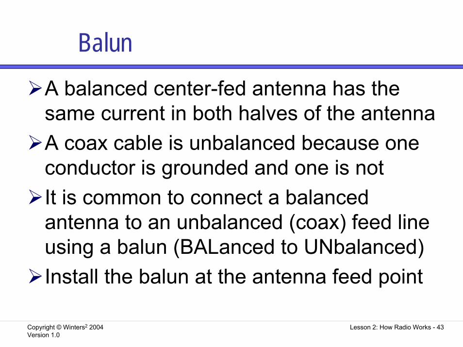
BalunA balanced center-fed antenna has the same current in both halves of the antennaA coax cable is unbalanced because one conductor is grounded and one is notIt is common to connect a balanced antenna to an unbalanced (coax) feed line using a balun (BALanced to UNbalanced)Install the balun at the antenna feed point
Copyright © Winters2 2004Version 1.0
Lesson 2: How Radio Works - 44
Exam QuestionsThe following slides contain questions from the exam pool that are covered in this section of the notes
Copyright © Winters2 2004Version 1.0
Lesson 2: How Radio Works - 45
T2B18T2B18 What emissions do a transmitter using a reactance modulator produce?
A. CW B. Test C. Single-sideband, suppressed-carrier phone D. Phase-modulated phone
Copyright © Winters2 2004Version 1.0
Lesson 2: How Radio Works - 46
T2B19T2B19 What other emission does phase modulation most resemble?
A. Amplitude modulation B. Pulse modulation C. Frequency modulation D. Single-sideband modulation
Copyright © Winters2 2004Version 1.0
Lesson 2: How Radio Works - 47
T8A08T8A08 Why is it important to provide adequate power supply filtering for a CW transmitter?
A. It isn't important, since CW transmitters cannot be modulated by AC hum B. To eliminate phase noise C. It isn't important, since most CW receivers can easily suppress any hum by using narrow filters D. To eliminate modulation of the RF signal by AC hum
Copyright © Winters2 2004Version 1.0
Lesson 2: How Radio Works - 48
T8B02T8B02 How is a CW signal usually transmitted?
A. By frequency-shift keying an RF signal B. By on/off keying an RF signal C. By audio-frequency-shift keying an oscillator tone D. By on/off keying an audio-frequency signal
Copyright © Winters2 2004Version 1.0
Lesson 2: How Radio Works - 49
T8B03T8B03 What purpose does block 1 serve in the simple CW transmitter pictured in Figure T8-1?
A. It detects the CW signal B. It controls the transmitter frequency C. It controls the transmitter output power D. It filters out spurious emissions from the transmitter
Copyright © Winters2 2004Version 1.0
Lesson 2: How Radio Works - 50
T8B04T8B04 What circuit is pictured in Figure T8-1 if block 1 is a variable-frequency oscillator?
A. A packet-radio transmitter B. A crystal-controlled transmitter C. A single-sideband transmitter D. A VFO-controlled transmitter
Copyright © Winters2 2004Version 1.0
Lesson 2: How Radio Works - 51
T8B05T8B05 What circuit is shown in Figure T8-2 if block 1 represents a reactance modulator?
A. A single-sideband transmitter B. A double-sideband AM transmitter C. An FM transmitter D. A product transmitter
Copyright © Winters2 2004Version 1.0
Lesson 2: How Radio Works - 52
T8B06T8B06 How would the output of the FM transmitter shown in Figure T8-2 be affected if the audio amplifier failed to operate (assuming block 1 is a reactance modulator)?
A. There would be no output from the transmitter B. The output would be 6-dB below the normal output power C. The transmitted audio would be distorted but understandableD. The output would be an unmodulated carrier
Copyright © Winters2 2004Version 1.0
Lesson 2: How Radio Works - 53
T8B12T8B12 What is the result of over deviation in an FM transmitter?
A. Increased transmitter power B. Out-of-channel emissions C. Increased transmitter range D. Poor carrier suppression
Copyright © Winters2 2004Version 1.0
Lesson 2: How Radio Works - 54
T8B13T8B13 What can you do if you are told your FM hand-held or mobile transceiver is over deviating?
A. Talk louder into the microphone B. Let the transceiver cool off C. Change to a higher power level D. Talk farther away from the microphone
Copyright © Winters2 2004Version 1.0
Lesson 2: How Radio Works - 55
T8C09T8C09 Why is FM voice so effective for local VHF/UHF radio communications?
A. The carrier is not detectable B. It is more resistant to distortion caused by reflected signals than the AM modes C. It has audio that is less affected by interference from static-type electrical noise than the AM modes D. Its RF carrier stays on frequency better than the AM modes
Copyright © Winters2 2004Version 1.0
Lesson 2: How Radio Works - 56
T8F14T8F14 What is the minimum FCC certification required for an amateur radio operator to build or modify their own transmitting equipment?
A. A First-Class Radio Repair License B. A Technician class license C. A General class license D. An Amateur Extra class license
Copyright © Winters2 2004Version 1.0
Lesson 2: How Radio Works - 57
T8A02T8A02 If your mobile transceiver works in your car but not in your home, what should you check first?
A. The power supply B. The speaker C. The microphone D. The SWR meter
Copyright © Winters2 2004Version 1.0
Lesson 2: How Radio Works - 58
T8A09T8A09 Why is it important to provide adequate DC source supply filtering for a mobile transmitter or transceiver?
A. To reduce AC hum and carrier current device signals B. To provide an emergency power source C. To reduce stray noise and RF pick-up D. To allow the use of smaller power conductors
Copyright © Winters2 2004Version 1.0
Lesson 2: How Radio Works - 59
T8B08T8B08 A mobile radio may be operated at home with the addition of which piece of equipment?
A. An alternator B. A power supply C. A linear amplifier D. A rhombic antenna
Copyright © Winters2 2004Version 1.0
Lesson 2: How Radio Works - 60
T8B09T8B09 What might you use instead of a power supply for home operation of a mobile radio?
A. A filter capacitor B. An alternator C. A 12-volt battery D. A linear amplifier
Copyright © Winters2 2004Version 1.0
Lesson 2: How Radio Works - 61
T8B10T8B10 What device converts 120 V AC to 12 V DC?
A. A catalytic converter B. A low-pass filter C. A power supply D. An RS-232 interface
Copyright © Winters2 2004Version 1.0
Lesson 2: How Radio Works - 62
T8C01T8C01 What type of circuit does Figure T8-5 represent if block 1 is a product detector?
A. A simple phase modulation receiver B. A simple FM receiver C. A simple CW and SSB receiver D. A double-conversion multiplier
Copyright © Winters2 2004Version 1.0
Lesson 2: How Radio Works - 63
T8C02T8C02 If Figure T8-5 is a diagram of a simple single-sideband receiver, what type of circuit should be shown in block 1?
A. A high pass filter B. A ratio detector C. A low pass filter D. A product detector
Copyright © Winters2 2004Version 1.0
Lesson 2: How Radio Works - 64
T8C03T8C03 What circuit is pictured in Figure T8-6, if block 1 is a frequency discriminator?
A. A double-conversion receiver B. A variable-frequency oscillator C. A superheterodyne receiver D. An FM receiver
Copyright © Winters2 2004Version 1.0
Lesson 2: How Radio Works - 65
T8C04T8C04 What is block 1 in the FM receiver shown in Figure T8-6?
A. A frequency discriminator B. A product detector C. A frequency-shift modulator D. A phase inverter
Copyright © Winters2 2004Version 1.0
Lesson 2: How Radio Works - 66
T8C05T8C05 What would happen if block 1 failed to function in the FM receiver diagram shown in Figure T8-6?
A. The audio output would sound loud and distorted B. There would be no audio output C. There would be no effect D. The receiver's power supply would be short-circuited
Copyright © Winters2 2004Version 1.0
Lesson 2: How Radio Works - 67
T8C06T8C06 What circuit function is found in all types of receivers?
A. An audio filter B. A beat-frequency oscillator C. A detector D. An RF amplifier
Copyright © Winters2 2004Version 1.0
Lesson 2: How Radio Works - 68
T8C07T8C07 What is one accurate way to check the calibration of your receiver's tuning dial?
A. Monitor the BFO frequency of a second receiver B. Tune to a popular amateur net frequency C. Tune to one of the frequencies of station WWV or WWVH D. Tune to another amateur station and ask what frequency the operator is using
Copyright © Winters2 2004Version 1.0
Lesson 2: How Radio Works - 69
T8C08T8C08 What circuit combines signals from an IF amplifier stage and a beat-frequency oscillator (BFO), to produce an audio signal?
A. An AGC circuit B. A detector circuit C. A power supply circuit D. A VFO circuit
Copyright © Winters2 2004Version 1.0
Lesson 2: How Radio Works - 70
T8C10T8C10 Why do many radio receivers have several IF filters of different bandwidths that can be selected by the operator?
A. Because some frequency bands are wider than others B. Because different bandwidths help increase the receiver sensitivity C. Because different bandwidths improve S-meter readings D. Because some emission types need a wider bandwidth than others to be received properly
Copyright © Winters2 2004Version 1.0
Lesson 2: How Radio Works - 71
T8C11T8C11 What is the function of a mixer in asuperheterodyne receiver?
A. To cause all signals outside of a receiver'spassband to interfere with one another B. To cause all signals inside of a receiver'spassband to reinforce one another C. To shift the frequency of the received signal so that it can be processed by IF stages D. To interface the receiver with an auxiliary device, such as a TNC
Copyright © Winters2 2004Version 1.0
Lesson 2: How Radio Works - 72
T8C12T8C12 What frequency or frequencies could the radio shown in Figure T8-7 receive?
A. 136.3 MHz B. 157.7 MHz and 10.7 MHz C. 10.7 MHz D. 147.0 MHz and 168.4 MHz
Copyright © Winters2 2004Version 1.0
Lesson 2: How Radio Works - 73
T8C13T8C13 What type of receiver is shown in Figure T8-7?
A. Direct conversion B. Superregenerative C. Single-conversion superheterodyne D. Dual conversion superheterodyne
Copyright © Winters2 2004Version 1.0
Lesson 2: How Radio Works - 74
T8C14T8C14 What emission mode could the receiver in Figure T8-7 detect?
A. AM B. FM C. Single sideband (SSB) D. CW
Copyright © Winters2 2004Version 1.0
Lesson 2: How Radio Works - 75
T8C15T8C15 Where should the squelch be set for the proper operation of an FM receiver?
A. Low enough to hear constant background noise B. Low enough to hear chattering background noise C. At the point that just silences background noise D. As far beyond the point of silence as the knob will turn
Copyright © Winters2 2004Version 1.0
Lesson 2: How Radio Works - 76
T8F09T8F09 What is used to measure relative signal strength in a receiver?
A. An S meter B. An RST meter C. A signal deviation meter D. An SSB meter
Copyright © Winters2 2004Version 1.0
Lesson 2: How Radio Works - 77
T8F16T8F16 Where would you connect a voltmeter to a 12-volt transceiver if you think the supply voltage may be low when you transmit?
A. At the battery terminals B. At the fuse block C. Midway along the 12-volt power supply wire D. At the 12-volt plug on the chassis of the equipment
Copyright © Winters2 2004Version 1.0
Lesson 2: How Radio Works - 78
T8F17T8F17 If your mobile transceiver does not power up, what might you check first?
A. The antenna feedpoint B. The coaxial cable connector C. The microphone jack D. The 12-volt fuses
Copyright © Winters2 2004Version 1.0
Lesson 2: How Radio Works - 79
T8A03T8A03 Which of the following devices would you need to conduct Amateur Radio communications using a data emission?
A. A telegraph key B. A computer C. A transducer D. A telemetry sensor
Copyright © Winters2 2004Version 1.0
Lesson 2: How Radio Works - 80
T8A10T8A10 What would you connect to a transceiver for RTTY operation?
A. A modem and a teleprinter or computer system B. A computer, a printer and a RTTY refresh unit C. A data-inverter controller D. A modem, a monitor and a DTMF keypad
Copyright © Winters2 2004Version 1.0
Lesson 2: How Radio Works - 81
T8A12T8A12 What might happen if you set your receiver's signal squelch too low while attempting to receive packet mode transmissions?
A. Noise may cause the TNC to falsely detect a data carrier B. Weaker stations may not be received C. Transmission speed and throughput will be reduced D. The TNC could be damaged
Copyright © Winters2 2004Version 1.0
Lesson 2: How Radio Works - 82
T8A13T8A13 What is one common method of transmitting RTTY on VHF/UHF bands?
A. Frequency shift the carrier to indicate mark and space at the receiver B. Amplitude shift the carrier to indicate mark and space at the receiver C. Key the transmitter on to indicate space and off for mark D. Modulate a conventional FM transmitter with a modem
Copyright © Winters2 2004Version 1.0
Lesson 2: How Radio Works - 83
T8A01T8A01 What two bands are most commonly used by "dual band" hand-held transceivers?
A. 6 meters and 2 meters B. 2 meters and 1.25 meters C. 2 meters and 70 cm D. 70 cm and 23 cm
Copyright © Winters2 2004Version 1.0
Lesson 2: How Radio Works - 84
T8A04T8A04 Which of the following devices would be useful to create an effective Amateur Radio station for weak-signal VHF communication?
A. A hand-held VHF FM transceiver B. A multi-mode VHF transceiver C. An Omni-directional antenna D. A mobile VHF FM transceiver
Copyright © Winters2 2004Version 1.0
Lesson 2: How Radio Works - 85
T8A05T8A05 What would you connect to a transceiver for voice operation?
A. A splatter filter B. A terminal-voice controller C. A receiver audio filter D. A microphone
Copyright © Winters2 2004Version 1.0
Lesson 2: How Radio Works - 86
T8A06T8A06 What would you connect to a transceiver to send Morse code?
A. A key-click filter B. A telegraph key C. An SWR meter D. An antenna switch
Copyright © Winters2 2004Version 1.0
Lesson 2: How Radio Works - 87
T8A07T8A07 What do many amateurs use to help form good Morse code characters?
A. A key-operated on/off switch B. An electronic keyer C. A key-click filter D. A DTMF keypad
Copyright © Winters2 2004Version 1.0
Lesson 2: How Radio Works - 88
T8A11T8A11 What might you connect between your transceiver and an antenna switch connected to several antennas?
A. A high-pass filter B. An SWR meter C. A key-click filter D. A mixer
Copyright © Winters2 2004Version 1.0
Lesson 2: How Radio Works - 89
T8A14T8A14 What would you use to connect a dual-band antenna to a mobile transceiver that has separate VHF and UHF output connectors?
A. A dual-needle SWR meter B. A full-duplex phone patch C. Twin high-pass filters D. A duplexer
Copyright © Winters2 2004Version 1.0
Lesson 2: How Radio Works - 90
T8B01T8B01 Can a transceiver designed for FM phone operation also be used for single sideband in the weak-signal portion of the 2-meter band?
A. Yes, with simple modification B. Only if the radio is a "multimode" radio C. Only with the right antenna D. Only with the right polarization
Copyright © Winters2 2004Version 1.0
Lesson 2: How Radio Works - 91
T8B11T8B11 What device could boost the low-power output from your hand-held radio up to 100 watts?
A. A voltage divider B. A power amplifier C. A impedance network D. A voltage regulator
Copyright © Winters2 2004Version 1.0
Lesson 2: How Radio Works - 92
T8B14T8B14 In Figure T8-3, if block 1 is a transceiver and block 3 is a dummy antenna, what is block 2?
A. A terminal-node switch B. An antenna switch C. A telegraph key switch D. A high-pass filter
Copyright © Winters2 2004Version 1.0
Lesson 2: How Radio Works - 93
T8B16T8B16 In Figure T8-4, if block 1 is a transceiver and block 2 is an SWR meter, what is block 3?
A. An antenna switch B. An antenna tuner C. A key-click filter D. A terminal-node controller
Copyright © Winters2 2004Version 1.0
Lesson 2: How Radio Works - 94
T8B17T8B17 In Figure T8-4, if block 1 is a transceiver and block 3 is an antenna tuner, what is block 2?
A. A terminal-node switch B. A dipole antenna C. An SWR meter D. A high-pass filter
Copyright © Winters2 2004Version 1.0
Lesson 2: How Radio Works - 95
T8B18T8B18 In Figure T8-4, if block 2 is an SWR meter and block 3 is an antenna tuner, what is block 1?
A. A terminal-node switch B. A power supply C. A telegraph key switch D. A transceiver
Copyright © Winters2 2004Version 1.0
Lesson 2: How Radio Works - 96
T8D22T8D22 What device might allow use of an antenna on a band it was not designed for?
A. An SWR meter B. A low-pass filter C. An antenna tuner D. A high-pass filter
Copyright © Winters2 2004Version 1.0
Lesson 2: How Radio Works - 97
T8E05T8E05 What does an antenna tuner do?
A. It matches a transceiver output impedance to the antenna system impedance B. It helps a receiver automatically tune in stations that are far away C. It switches an antenna system to a transceiver when sending, and to a receiver when listening D. It switches a transceiver between different kinds of antennas connected to one feed line
Copyright © Winters2 2004Version 1.0
Lesson 2: How Radio Works - 98
T8E06T8E06 What is a coaxial cable?
A. Two wires side-by-side in a plastic ribbon B. Two wires side-by-side held apart by insulating rods C. Two wires twisted around each other in a spiral D. A center wire inside an insulating material covered by a metal sleeve or shield
Copyright © Winters2 2004Version 1.0
Lesson 2: How Radio Works - 99
T8E07T8E07 Why should you use only good quality coaxial cable and connectors for a UHF antenna system?
A. To keep RF loss low B. To keep television interference high C. To keep the power going to your antenna system from getting too high D. To keep the standing-wave ratio of your antenna system high
Copyright © Winters2 2004Version 1.0
Lesson 2: How Radio Works -100
T8E08T8E08 What is parallel-conductor feed line?
A. Two wires twisted around each other in a spiral B. Two wires side-by-side held apart by insulating material C. A center wire inside an insulating material that is covered by a metal sleeve or shield D. A metal pipe that is as wide or slightly wider than a wavelength of the signal it carries
Copyright © Winters2 2004Version 1.0
Lesson 2: How Radio Works -101
T8E09T8E09 (D) Which of the following are some reasons to use parallel-conductor, open-wire feed line?
A. It has low impedance and will operate with a high SWR B. It will operate well even with a high SWR and it works well when tied down to metal objects C. It has a low impedance and has less loss than coaxial cable D. It will operate well even with a high SWR and has less loss than coaxial cable
Copyright © Winters2 2004Version 1.0
Lesson 2: How Radio Works -102
T8E12T8E12 What happens to radio energy when it is sent through a poor quality coaxial cable?
A. It causes spurious emissions B. It is returned to the transmitter's chassis ground C. It is converted to heat in the cable D. It causes interference to other stations near the transmitting frequency
Copyright © Winters2 2004Version 1.0
Lesson 2: How Radio Works -103
T8E13T8E13 What is an unbalanced line?
A. A feed line with neither conductor connected to ground B. A feed line with both conductors connected to ground C. A feed line with one conductor connected to ground D. All of these answers are correct
Copyright © Winters2 2004Version 1.0
Lesson 2: How Radio Works -104
T8E01T8E01 What does standing-wave ratio mean?
A. The ratio of maximum to minimum inductances on a feed line B. The ratio of maximum to minimum capacitances on a feed line C. The ratio of maximum to minimum impedances on a feed line D. The ratio of maximum to minimum voltages on a feed line
Copyright © Winters2 2004Version 1.0
Lesson 2: How Radio Works -105
T8E02T8E02 What instrument is used to measure standing wave ratio?
A. An ohmmeter B. An ammeter C. An SWR meter D. A current bridge
Copyright © Winters2 2004Version 1.0
Lesson 2: How Radio Works -106
T8E03T8E03 What would an SWR of 1:1 indicate about an antenna system?
A. That the antenna was very effective B. That the transmission line was radiating C. That the antenna was reflecting as much power as it was radiating D. That the impedance of the antenna and its transmission line were matched
Copyright © Winters2 2004Version 1.0
Lesson 2: How Radio Works -107
T8E04T8E04 What does an SWR reading of 4:1 mean?
A. An impedance match that is too low B. An impedance match that is good, but not the best C. An antenna gain of 4 D. An impedance mismatch; something may be wrong with the antenna system
Copyright © Winters2 2004Version 1.0
Lesson 2: How Radio Works -108
T8E10T8E10 What does "balun" mean?
A. Balanced antenna network B. Balanced unloader C. Balanced unmodulator D. Balanced to unbalanced
Copyright © Winters2 2004Version 1.0
Lesson 2: How Radio Works -109
T8E11T8E11 Where would you install a balun to feed a dipole antenna with 50-ohm coaxial cable?
A. Between the coaxial cable and the antenna B. Between the transmitter and the coaxial cable C. Between the antenna and the ground D. Between the coaxial cable and the ground
Copyright © Winters2 2004Version 1.0
Lesson 2: How Radio Works -110
T8E14T8E14 What point in an antenna system is called the feed point?
A. The antenna connection on the back of the transmitter B. Halfway between the transmitter and the feed line C. At the point where the feed line joins the antenna D. At the tip of the antenna
Copyright © Winters2 2004Version 1.0
Lesson 2: How Radio Works -111
T8F10T8F10 With regard to a transmitter and antenna system, what does "forward power" mean?
A. The power traveling from the transmitter to the antenna B. The power radiated from the top of an antenna system C. The power produced during the positive half of an RF cycle D. The power used to drive a linear amplifier
Copyright © Winters2 2004Version 1.0
Lesson 2: How Radio Works -112
T8F11T8F11 With regard to a transmitter and antenna system, what does "reflected power" mean?
A. The power radiated down to the ground from an antenna B. The power returned towards the source on a transmission line C. The power produced during the negative half of an RF cycle D. The power returned to an antenna by buildings and trees
Copyright © Winters2 2004Version 1.0
Lesson 2: How Radio Works -113
T8F12T8F12 At what line impedance do most RF watt meters usually operate?
A. 25 ohms B. 50 ohms C. 100 ohms D. 300 ohms
Copyright © Winters2 2004Version 1.0
Lesson 2: How Radio Works -114
T8F13T8F13 If a directional RF wattmeter reads 90 watts forward power and 10 watts reflected power, what is the actual transmitter output power?
A. 10 watts B. 80 watts C. 90 watts D. 100 watts