Embed Size (px)
Citation preview

Name…………………Class…………..
science-spark.co.uk
G482Electrons, Photons and Waves
Module 2.4: Waves
©2011 science-spark.co.uk RAB Plymstock School

G482 Module 2.4 Waves
1. Wave equation 2.4.1 Wave motionCandidates should be able to:(a) describe and distinguish between progressive longitudinal and transverse waves;(b) define and use the terms displacement, amplitude, wavelength, period, phase difference, frequency and speed of a wave;(c) derive from the definitions of speed, frequency and wavelength, the wave equation v = fλ;(d) select and use the wave equation v = fλ;
Progressive, longitudinal, transverse, displacement, amplitude, wavelength, period, phase difference, frequency, speed, velocity
2. Reflection and Refraction
(e) explain what is meant by reflection, refraction and diffraction of waves such as sound and light.
Reflection, refraction, speed, echo, sonar
3. Diffraction (e) explain what is meant by reflection, refraction and diffraction of waves such as sound and light.
Diffraction, wavelength, interference, constructive, destructive, transverse, longitudinal.
4. Electromagnetic Waves
2.4.2 Electromagnetic wavesCandidates should be able to:(a) state typical values for the wavelengths of the different regions of the electromagnetic spectrum from radio waves to γ-rays;(b) state that all electromagnetic waves travel at the same speed in a vacuum;(c) describe differences and similarities between different regions of the electromagnetic spectrum;
Wavelength, frequency, spectrum, speed, vacuum.
5. Uses of Electromagnetic Waves
2.4.2 Electromagnetic wavesCandidates should be able to:(d) describe some of the practical uses of electromagnetic waves;(e) describe the characteristics and dangers of UV-A, UV-B and UV-C radiations and explain the role of sunscreen (HSW 6a);
UV-A, UV-B, UV-C, radiation, sunscreen
6. Polarization and Malus’ Law
(f) explain what is meant by plane polarised waves and understand the polarisation of electromagnetic waves;(g) explain that polarisation is a phenomenon associated with transverse waves only;(h) state that light is partially polarised on reflection; (i) recall and apply Malus’s law for transmitted intensity of light from a polarising filter.
Plane, polarise, transverse, longitudinal, reflection, transmit, intensity, filter.
7. Interference 2.4.3 InterferenceCandidates should be able to:(a) state and use the principle of superposition of waves;(b) apply graphical methods to illustrate the principle of superposition;(c) explain the terms interference, coherence, path difference and phase difference;(d) state what is meant by constructive interference and destructive interference;
Superposition, interference, coherence, path difference, phase difference, constructive, destructive
8. 2 Source Interference
(e) describe experiments that demonstrate two source interference using sound, light and microwaves;(f) describe constructive interference and destructive interference in terms of path difference and phase difference;
Interference, constructive, destructive, path difference, phase difference, intensity, power, amplitude
9. Intensity (g) use the relationships intensity = power/cross-sectional areaintensity = k x amplitude2 ;
intensity, power, amplitude
©2011 science-spark.co.uk RAB Plymstock School

10. Young’s Slits (h) describe the Young double-slit experiment and explain how it is a classical confirmation of the wave-nature of light (HSW 1);(i) Select and use the equationλ = ax D for electromagnetic waves;(j) describe an experiment to determine the wavelength of monochromatic light using a laser and a double slit (HSW 1);
Young double slit, wavelength, slit width, slit separation, distance to screen, monochromatic (laser)
11. Diffraction gratings (k) describe the use of a diffraction grating to determine the wavelength of light (the structure and use of a spectrometer are not required);(l) select and use the equation dsinθ = nλ;(m) explain the advantages of using multiple slits in an experiment to find the wavelength of light.
Diffraction, diffraction grating, wavelength, frequency, coherence, path difference, phase difference.
12. Stationary Waves 2.4.4 Stationary wavesCandidates should be able to:(a) explain the formation of stationary (standing) waves using graphical methods;(b) describe the similarities and differences between progressive and stationary waves;(c) define the terms nodes and antinodes;
Progressive, stationary, graphical, node, antinode
13. Stationary Waves and resonance
(d) describe experiments to demonstrate stationary waves using microwaves, stretched strings and air columns;(e) determine the standing wave patterns for stretched string and air columns in closed and open pipes;(f) use the equation: separation between adjacent nodes (or antinodes) = λ/2;(g) define and use the terms fundamental mode of vibration and harmonics;(h) determine the speed of sound in air from measurements on stationary waves in a pipe closed at one end.
Standing, progressive, node, antinode
14. G482 Module 4: 2.4 Waves Test
Review topic
©2011 science-spark.co.uk RAB Plymstock School

Lesson 21 notes – The wave equationObjectives(a) describe and distinguish between progressive longitudinal and transverse waves;(b) define and use the terms displacement, amplitude, wavelength, period, phase difference, frequency and speed of a wave;(c) derive from the definitions of speed, frequency and wavelength, the wave equation v = fλ;(d) select and use the wave equation v = fλ;
The Anatomy of a Wave
A transverse wave is a wave in which the particles of the medium are displaced in a direction perpendicular to the direction of energy transport. A transverse wave can be created in a rope if the rope is stretched out horizontally and the end is vibrated back-and-forth in a vertical direction. If a snapshot of such a transverse wave could be taken so as to freeze the shape of the rope in time, then it would look like the following diagram.
The dashed line drawn through the center of the diagram represents the equilibrium or rest position of the string. This is the position that the string would assume if there were no disturbance moving through it. Once a disturbance is introduced into the string, the particles of the string begin to vibrate upwards and downwards. At any given moment in time, a particle on the medium could be above or below the rest position. Points A and F on the diagram represent the crests of this wave. The crest of a wave is the point on the medium which exhibits the maximum amount of positive or upwards displacement from the rest position. Points D and I on the diagram represent the troughs of this wave. The trough of a wave is the point on the medium which exhibits the maximum amount of negative or downwards displacement from the rest position.
The wave shown above can be described by a variety of properties. One such property is amplitude. The amplitude of a wave refers to the maximum amount of displacement of a a particle on the medium from its rest position. In a sense, the amplitude is the distance from rest to crest. Similarly, the amplitude can be measured from the rest position to the trough position. In the diagram above, the amplitude could be measured as the distance of a line segment which is perpendicular to the rest position and extends vertically upward from the rest position to point A.
The wavelength is another property of a wave which is portrayed in the diagram above. The wavelength of a wave is simply the length of one
©2011 science-spark.co.uk RAB Plymstock School

complete wave cycle. If you were to trace your finger across the wave in the diagram above, you would notice that your finger repeats its path. A wave has a repeating pattern. And the length of one such repetition (known as a wave cycle) is the wavelength. The wavelength can be measured as the distance from crest to crest or from trough to trough. In fact, the wavelength of a wave can be measured as the distance from a point on a wave to the corresponding point on the next cycle of the wave. In the diagram above, the wavelength is the horizontal distance from A to F, or the horizontal distance from B to G, or the horizontal distance from E to J, or the horizontal distance from D to I, or the horizontal distance from C to H. Any one of these distance measurements would suffice in determining the wavelength of this wave.
A longitudinal wave is a wave in which the particles of the medium are displaced in a direction parallel to the direction of energy transport. A longitudinal wave can be created in a slinky if the slinky is stretched out horizontally and the end coil is vibrated back-and-forth in a horizontal direction. If a snapshot of such a longitudinal wave could be taken so as to freeze the shape of the slinky in time, then it would look like the following diagram.
Because the coils of the slinky are vibrating longitudinally, there are regions where they become pressed together and other regions where they are spread apart. A region where the coils are pressed together in a small amount of space is known as a compression. A compression is a point on a medium through which a longitudinal wave is travelling which has the maximum density. A region where the coils are spread apart, thus maximizing the distance between coils, is known as a rarefaction. A rarefaction is a point on a medium through which a longitudinal wave is travelling which has the minimum density. Points A, C and E on the diagram above represent compressions and points B, D, and F represent rarefactions. While a transverse wave has an alternating pattern of crests and troughs, a longitudinal wave has an alternating pattern of compressions and rarefactions.
As discussed above, the wavelength of a wave is the length of one complete cycle of a wave. For a transverse wave, the wavelength is determined by measuring from crest to crest. A longitudinal wave does not have crest; so how can its wavelength be determined? The wavelength can always be determined by measuring the distance between any two corresponding points on adjacent waves. In the case of a longitudinal wave, a wavelength measurement is made by measuring the distance from a compression to the next compression or from a rarefaction to the next rarefaction. On the diagram above, the distance from point A to point C or from point B to point D would be representative of the wavelength.
©2011 science-spark.co.uk RAB Plymstock School

Deducing and using the wave equation
Justification/deduction of the wave equation v = f λ.
Lets use an example of the coaches of a train are going past;
You count how many coaches go by in a second and you know the length of one – so you multiply the two together to get the train’s speed. Apply this to waves: count the number of waves passing each second (= frequency), and multiply by the length of each (= wavelength) to find the speed.
speed = distance/time = l/T= l / (1/f) = f λ.
So v = f λ
Which becomes: c = f λ as c is the speed of light.
You must practice and be able to rearrange this to find f or λ.
©2011 science-spark.co.uk RAB Plymstock School

Lesson 21 – The wave equation1 (a) Define the following terms associated with waves.
(i) frequency f..........................................................................................................................................................................................................................................................................[1]
(ii) wavelength λ......................................................................................................................................................................................................................................................................[1]
(b) Use the definitions in (a) to deduce an equation for the speed v of a wave in terms of λ and f.
[3](c) (i) The speed of sound in air is about 340 m s–1 while light travels at a
speed of 3.0 × 10⁸ m s–1. Calculate the time interval between seeing a flash of lightning, 1.0 km away, and hearing the sound of thunder caused by the lightning.
time interval = ....................................................... s [3]
(ii) Describe how observers may estimate their distance away from the point of a flash of lightning.
.......................................................................................................................................
.......................................................................................................................................
...................................................................................................................................[1]
(d) State two differences, other than their speeds, between sound and light waves..................................................................................................................................................................................................................................................................................................................................................................................................................[2]
[Total: 11]
Turn over for question 22 Label both of the diagrams appropriately with the key words below. You can
use some of the keywords on both diagrams. You will gain one mark for each correct use of the word (maximum of once per diagram)
Transverse, Longitudinal, Amplitude, Wavelength, compression, rarefaction, crest, trough
©2011 science-spark.co.uk RAB Plymstock School

Total [9]
©2011 science-spark.co.uk RAB Plymstock School

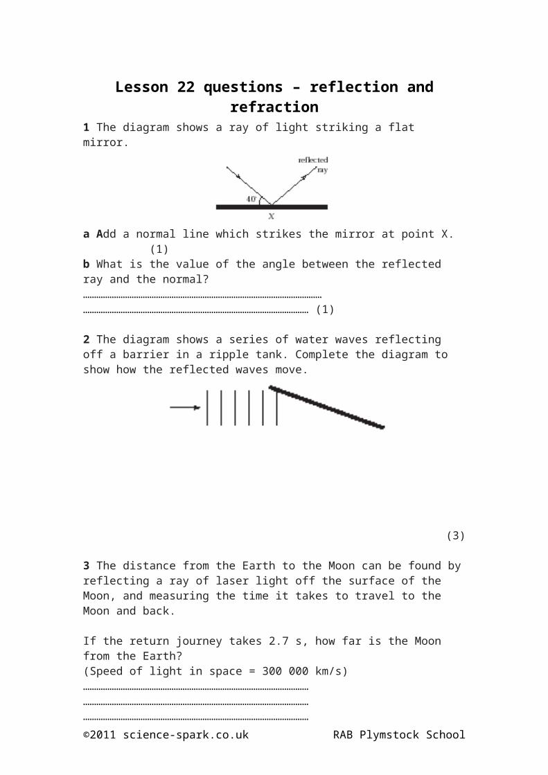
Lesson 22 questions – reflection and refraction1 The diagram shows a ray of light striking a flat mirror.
a Add a normal line which strikes the mirror at point X. (1)b What is the value of the angle between the reflected ray and the normal?………………………………………………………………………………………………………………………………………………………………………………………… (1)
2 The diagram shows a series of water waves reflecting off a barrier in a ripple tank. Complete the diagram to show how the reflected waves move.
(3)
3 The distance from the Earth to the Moon can be found by reflecting a ray of laser light off the surface of the Moon, and measuring the time it takes to travel to the Moon and back.
If the return journey takes 2.7 s, how far is the Moon from the Earth?(Speed of light in space = 300 000 km/s)………………………………………………………………………………………………………………………………………………………………………………………………………………………………………………………………………………………………………………………………………………………………………… (2)
4 The diagram shows what happens when light waves travel from air into glass.
Their wavelength and speed change; their frequency is unaffected.
©2011 science-spark.co.uk RAB Plymstock School

a Does their wavelength increase or decrease?………………………………………………………………………………………… (1)
b Does their speed increase or decrease?………………………………………………………………………………………… (1)
5 Explain why non-swimmers should be wary of diving into a pool of water even if they think they can see the bottom?…………………………………………………………………………………………………………………………………………………………………………………………………………………………………………………………………………… (2)
6 Sketch on the path of the light as it is refracted through the transparent block. Label the diagram fully.
(4)7 Explain what refraction is and how it occurs.……………………………………………………………………………………………………………………………………………………………………………………………………………………………………………………………………………………………………………………………………………………………………………………………………………………………………………………………………………………………………………………………………………………………………………………………………………………………………………………… (3)
8 i) a) Plot a bar chart to show the figures in the table above on the graph paper below.
(3)b) Which material slows the speed of light the most?
………………………………. (1)
©2011 science-spark.co.uk RAB Plymstock School
Material Speed of lightair 300 000 km/s
water 225 000 km/sdiamond 124 000 km/sperspex 201 000 km/s
glass 197 000 km/s
ii) When a ray of light goes from air into one of the other materials in the table:a which material refracts light rays the most?
………………………………………………………………………………………… (1)
b which material refracts light rays the least?………………………………………………………………………………………… (1)
©2011 science-spark.co.uk RAB Plymstock School

Lesson 23 notes – DiffractionObjectives(e) explain what is meant by reflection, refraction and diffraction of waves such as sound and light.
The wavelength of sound waves may be several metres.If the wavelength is of a similar size to a gap in a door, then the wave will diffract as shown below.
If the wavelength does not match the size of the gap,then only a little diffraction will occur at the edge of the wave.
The part of the wave which hits the wall in the above two pictures is reflected straight back on itself.
The amount of spread of the wave will depend on the path difference and the constructive or destructive interference that occurs because of this.
The Huygens' Principle says that every point on a wavefront acts like a new source so each transparent slit becomes a new source.
So the diffraction of light would look like this on a screen:
©2011 science-spark.co.uk RAB Plymstock School

So because of interference there will be maxima where there is constructive interference and minima where there is destructive interference.
©2011 science-spark.co.uk RAB Plymstock School

Lesson 23 questions – diffraction(a) State two differences between sound and light waves.1. ..............................................................................................................................................................................................................................................................................2. ..........................................................................................................................................................................................................................................................................[2](b) The diffraction of waves can be demonstrated using a ripple tank.(i) Describe how plane, transverse water waves can be produced in the ripple tank..................................................................................................................................................................................................................................................................................................................................................................................................................[2](ii) Explain how the wavelength of the water waves can be increased...........................................................................................................................................................................................................................................................................[1](iii) State how the speed of the water waves can be reduced...........................................................................................................................................................................................................................................................................[1](c) Fig. 5.1 shows plane water waves in a ripple tank approaching a narrow gap.On the diagram, draw the pattern of the wavefronts emerging from the gap. [3]
Fig. 5.1
(d) Explain why the diffraction of sound waves is much more likely to be noticeable than the diffraction of light................................................................................................................................................................................................................................................................................................................................................................................................................................................................................................................................................................................................................................................................................................[3]
[Total: 12]
©2011 science-spark.co.uk RAB Plymstock School

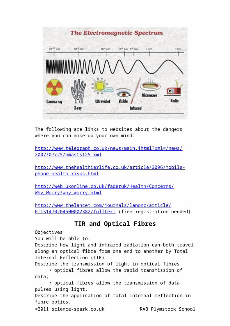
Lesson 24 notes – The EM spectrumObjectives(a) state typical values for the wavelengths of the different regions of the electromagnetic spectrum from radio waves to γ-rays;(b) state that all electromagnetic waves travel at the same speed in a vacuum;(c) describe differences and similarities between different regions of the electromagnetic spectrum;
Deducing and using the wave equation
Justification/deduction of the wave equation v = f λ.
Lets use an example of the coaches of a train are going past;
You count how many coaches go by in a second and you know the length of one – so you multiply the two together to get the train’s speed. Apply this to waves: count the number of waves passing each second (= frequency), and multiply by the length of each (= wavelength) to find the speed.
speed = distance/time = l/T= l / (1/f) = f λ.
So v = f λ
Which becomes: c = f λ as c is the speed of light.
You must practice and be able to rearrange this to find f or λ.
©2011 science-spark.co.uk RAB Plymstock School

The EM SpectrumHere is a review table of the information you should be able to recall.
Type of ray: Gamma rays: X-rays: Ultraviolet: Visible light:
Production:Emitted during
radioactive decay
Produced by firing electrons
at a metal target
Emitted by the Sun
Emitted by the Sun
Uses: Medicine in chemotherapy
Medicine for looking at
bonesTanning Seeing
Hazards:Causes cancer by damaging
cells
Causes cancer by damaging
cells
Can cause skin cancer
Intense light can
damage your sight
Wavelength (m): x10-12 x10-10 x10-8 7 x10⁻⁷ to
4x10⁻⁷
Frequency (Hz): x10 20 x10 18 x10 15 x10 14
Photon Energies
(eV):400 k 4 k 4 0.4
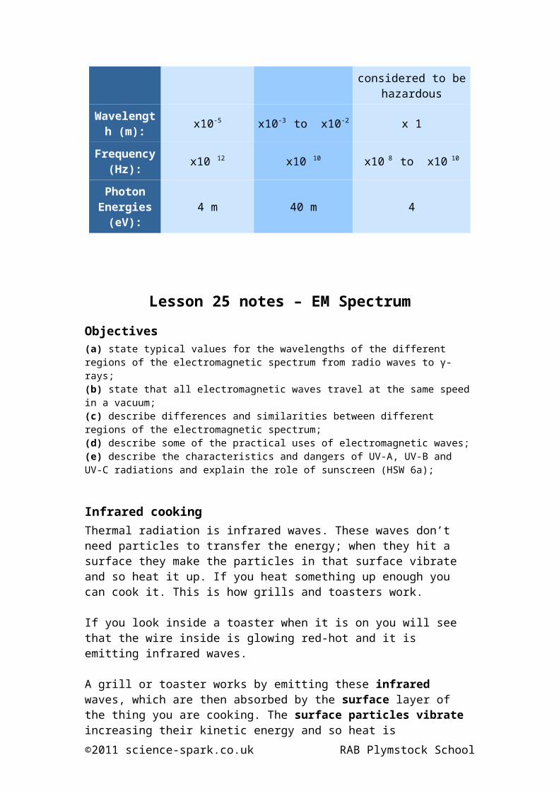
Type of ray: Infra red: Micro-waves: Radio-waves:
Production: Emitted by hot objects
Produced by changing currents
in a conductor
Produced by changing currents in
a conductor
Uses: Conventional cooking
Microwave cooking and
communications
Communication and media
Hazards: Can burn Can burnCurrently not
considered to be hazardous
Wavelength (m): x10-5 x10-3 to x10-2 x 1
Frequency (Hz): x10 12 x10 10 x10 8 to x10 10
Photon Energies
(eV):4 m 40 m 4
©2011 science-spark.co.uk RAB Plymstock School

Lesson 25 notes – EM SpectrumObjectives(a) state typical values for the wavelengths of the different regions of the electromagnetic spectrum from radio waves to γ-rays;(b) state that all electromagnetic waves travel at the same speed in a vacuum;(c) describe differences and similarities between different regions of the electromagnetic spectrum; (d) describe some of the practical uses of electromagnetic waves;(e) describe the characteristics and dangers of UV-A, UV-B and UV-C radiations and explain the role of sunscreen (HSW 6a);
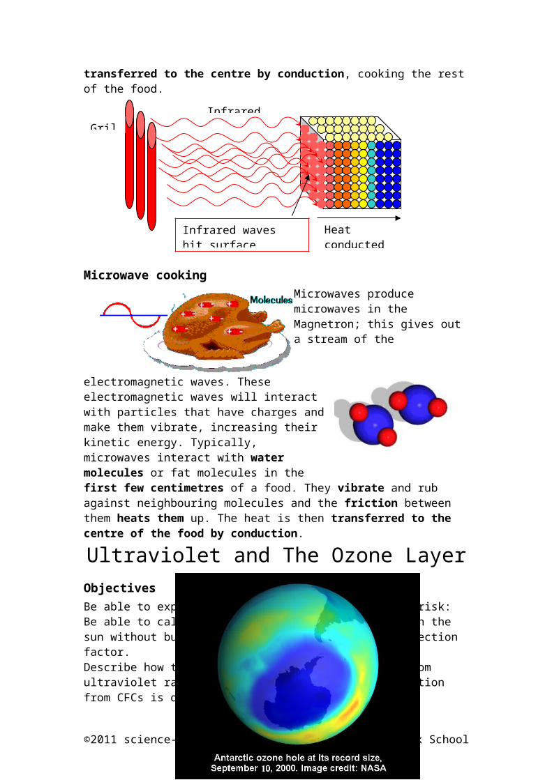
Infrared cookingThermal radiation is infrared waves. These waves don’t need particles to transfer the energy; when they hit a surface they make the particles in that surface vibrate and so heat it up. If you heat something up enough you can cook it. This is how grills and toasters work.
If you look inside a toaster when it is on you will see that the wire inside is glowing red-hot and it is emitting infrared waves.
A grill or toaster works by emitting these infrared waves, which are then absorbed by the surface layer of the thing you are cooking. The surface particles vibrate increasing their kinetic energy and so heat is transferred to the centre by conduction, cooking the rest of the food.
Microwave cookingMicrowaves produce microwaves in the Magnetron; this gives out a stream of the electromagnetic waves. These electromagnetic waves will interact with particles that have
charges and make them vibrate, increasing their kinetic energy. Typically, microwaves interact with water molecules or fat molecules in the first few centimetres of a food. They vibrate and rub against neighbouring molecules and the
©2011 science-spark.co.uk RAB Plymstock School
GrillInfrared waves
Heat conducted through food
Infrared waves hit surface particles

friction between them heats them up. The heat is then transferred to the centre of the food by conduction.
Ultraviolet and The Ozone LayerObjectivesBe able to explain how darker skins reduce cancer risk:Be able to calculate how long a person can spend in the sun without burning from knowledge of the sun protection factor.Describe how the ozone layer protects the Earth from ultraviolet radiation and that environmental pollution from CFCs is depleting the layer.
The Ozone LayerAbout 20 kilometres thick, this giant umbrella is made up of a layer of ozone (O3) gas.
This gas is found some 15 to 35 kilometres above the earth's surface in the upper atmosphere or "stratosphere". Ozone gas absorbs UV rays.
UV can be harmful because it can cause damage to skin cells and harm our eyes.Gases that are very useful to us in things like refrigerators called CFCs (Chlorofluorocarbons) react with Ozone gas (O3).•This causes the Ozone layer to thin (we call these thinned areas “holes”).•These gases have now been banned and the Ozone layer is reforming slowly.
©2011 science-spark.co.uk RAB Plymstock School

SunburnUVB rays are very short wavelengths of UV that all get absorbed by the ozone layer.
UVB rays are short wavelengths of UV light that reach the epidermis (the outer layer of skin).
UVA rays are longer wavelengths of UV light that penetrate the dermis (the second layer of skin).
Exension
Skin TypesDarker skins reduce cancer risk by:
absorbing more ultraviolet radiation in the epidermis
letting less ultraviolet radiation reach underlying body tissues where it is more damaging.
Example CalculationAlbert will get sunburn if he stays in the sun for 30 minutes. How many hours can he stay in the sun if he uses sunscreen with an SPF of 15?
Time (in minutes) = 30 x 15
= 450 minutes / 60 (to get hours)
= 7.5 hours
Radio communicationsObjectivesRecognise common uses of wireless technology.• Radio;• mobile phones.• laptop computers.Explain how long-distance communication depends on the reflection of waves from the Ionosphere or by being received and re-transmitted from satellites.Recognise that radio stations with similar transmission frequencies often interfere.©2011 science-spark.co.uk RAB Plymstock School
UVB UVA

Historyhttp://pass.maths.org.uk/issue8/features/phones/index.html
Uses
Wireless is a term used to describe telecommunications in which electromagnetic waves (rather than some form of wire) carry the signal over part or the entire communication path. Common examples of wireless equipment in use today include:
Cellular phones and pagers: provide connectivity for portable and mobile applications, both personal and business.
Global Positioning System (GPS): allows drivers of cars and trucks, captains of boats and ships, and pilots of aircraft to ascertain their location anywhere on earth.
Cordless computer peripherals: the cordless mouse is a common example; keyboards and printers can also be linked to a computer via wireless.
Cordless telephone sets: these are limited-range devices, not to be confused with cell phones.
Satellite television: allows viewers in almost any location to select from hundreds of channels.
Long Distance CommunicationRadio waves travel in straight lines; they can also be reflected and refracted since they are a wave and part of the electromagnetic spectrum. They have long wavelengths and do not lose energy easily.
These properties allow it to carry information for hundreds of miles.
The ionosphere The ionosphere is a set of ionized layers in the upper portions of the atmosphere that span the altitude range between about 75 and several hundred kilometers above Earth's surface.
Depending on the angle of incident radio waves, they can be reflected back towards the Earth over large open expanses such as the Atlantic Ocean to places where the radio waves would normally be stopped from getting because of the curvature of the Earth (the Earth is round).
©2011 science-spark.co.uk RAB Plymstock School
SatellitesAlthough slightly refracted through the ionosphere, radio waves can be transmitted to geostationary satellites and then retransmitted around the world as shown in the diagram.
Mobile phonesObjectivesRecognise that microwaves are used to transmit information over large distances that are in line of sight.Describe how diffraction and interference of microwaves can cause signal loss.
Mobile phone rangeMobile signals have a range of about 35km but can be absorbed and reflected by different materials. A concrete wall or metal lift can stop the signal completely. Other materials will also absorb them and signal strengths on your mobile can vary due to its position because of this.
Hillsides will stop transmission so mobile masts must be positioned on the tops of hills in line of sight of any users.
DiffractionDiffraction occurs around objects like buildings and hills and the diagram shows how, as the signal is spread out its strength reduces. The lighter the line, the weaker the signal.
©2011 science-spark.co.uk RAB Plymstock School
InterferenceInterference can happen when 2 signals with the same frequency are used close to each other. It can also happen when waves are received and then reflect off a nearby surface so you pick them up more than once.
Dangers of Mobile Phones?There may or may not be dangers to residents near to the site of a mast or to users of mobile phones.The energy associated with microwaves and infrared depend on their frequency. The higher the frequency, the higher energy the wave has.
The following are links to websites about the dangers where you can make up your own mind:
http://www.telegraph.co.uk/news/main.jhtml?xml=/news/2007/07/25/nmasts125.xml
http://www.thehealthierlife.co.uk/article/3096/mobile-phone-health-risks.html
http://web.ukonline.co.uk/faderuk/Health/Concerns/Why_Worry/why_worry.html
©2011 science-spark.co.uk RAB Plymstock School

http://www.thelancet.com/journals/lanonc/article/PIIS1470204500002382/fulltext (free registration needed)
TIR and Optical FibresObjectivesYou will be able to:Describe how light and infrared radiation can both travel along an optical fibre from one end to another by Total Internal Reflection (TIR).Describe the transmission of light in optical fibres
• optical fibres allow the rapid transmission of data;• optical fibres allow the transmission of data pulses using light.
Describe the application of total internal reflection in fibre optics.Describe advantages of using optical fibres to allow more information to be transmitted:
• multiplexing;• lack of interference.• no corrosion (unlike copper coaxial cable)
Optical Fibres
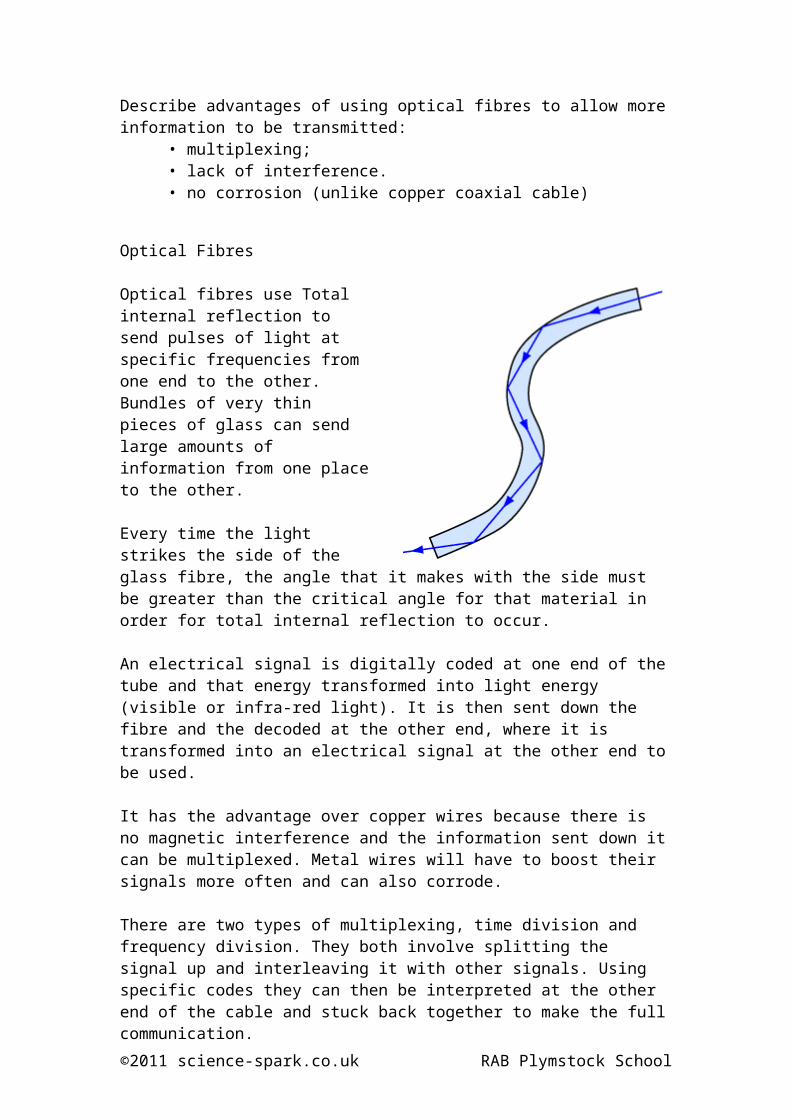
Optical fibres use Total internal reflection to send pulses of light at specific frequencies from one end to the other. Bundles of very thin pieces of glass can send large amounts of information from one place to the other.
Every time the light strikes the side of the glass fibre, the angle that it makes with the side must be greater than the critical angle for that material in order for total internal reflection to occur.
An electrical signal is digitally coded at one end of the tube and that energy transformed into light energy (visible or infra-red light). It is then sent down the fibre and the decoded at the other end, where it is transformed into an electrical signal at the other end to be used.
It has the advantage over copper wires because there is no magnetic interference and the information sent down it can be multiplexed. Metal wires will have to boost their signals more often and can also corrode.
There are two types of multiplexing, time division and frequency division. They both involve splitting the signal up and interleaving it with other signals. Using specific codes they can then be interpreted at the other end of the cable and stuck back together to make the full communication.
©2011 science-spark.co.uk RAB Plymstock School

Optical fibres are used for telecommunications, phone links and the internet. They are also used in medicine for laproscopic (keyhole) surgery.
Extension
Other Uses
Optical fibres can be used for the purposes of illumination, often carrying light from outside to rooms in the interiors of large buildings.
Another important application of optical fibres is in sensors. If a fibre is stretched or squeezed, heated or cooled or subjected to some other change of environment, there is usually a small but measurable change in light transmission. Hence, a rather cheap sensor can be made which can be put in a tank of acid, or near an explosion or in a mine and connected back, perhaps through kilometres of fibre, to a central point where the effects can be measured.
Optical fibres can also be used as simple light guides. At least one fancy modern car has a single high intensity lamp under its bonnet, with optical fibres taking the light to a series of mini-headlamps on the front. Less high tech versions carry light from bulbs to the glove compartment etc.
As light is not affected noticeably by electromagnetic fields. It also does not interfere with other instruments that do use electricity. For this reason, fibre-optics are also becoming very important for short-range communication and information transfer in applications situations like aircraft. This application is now being extended into motor cars, and plastic optical fibres will soon (say in 5-8 years time) be very common for transmitting information around the car.
So we can see that optical fibres are not just passive light pipes. Researchers are finding ways in which they can make the fibres become the active elements of the circuit, e.g. amplifiers or filters. This means that the information could remain in light form from one end of a link to the other, removing the limitations of the electronics in circuits and enabling more of the theoretical information carrying capacity to be used.
©2011 science-spark.co.uk RAB Plymstock School

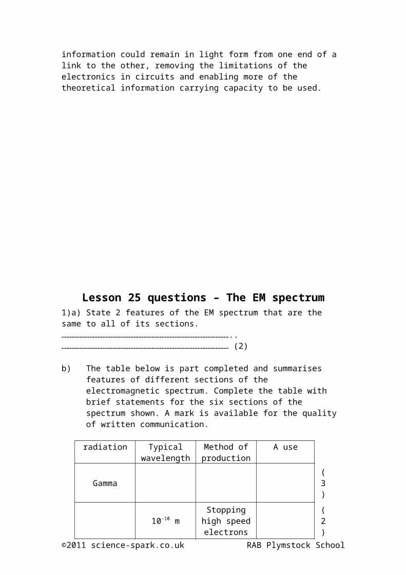
Lesson 25 questions – The EM spectrum1)a) State 2 features of the EM spectrum that are the same to all of its sections.…………………………………………………………………………………………..………………………………………………………………………………………… (2)
b) The table below is part completed and summarises features of different sections of the electromagnetic spectrum. Complete the table with brief statements for the six sections of the spectrum shown. A mark is available for the quality of written communication.
radiation Typical wavelength
Method of production
A use
Gamma (3)
10-10 mStopping high speed electrons
at a target(2)
10-8 m (3)
Light From very hot objects
Sight, photography (1)
Infra-red Heat from the Sun (2)
10mHigh frequency oscillation of
electrons(2)
c) A mobile telephone company transmits microwave signals to an orbiting satellite at a frequency of 1.6 x 10⁹Hz. Calculate the wavelength λ of the microwaves.……………………………………………………………………………………………………………………………………………………………………………………………………………………………………………………………………………… (3)
Total [19]
©2011 science-spark.co.uk RAB Plymstock School

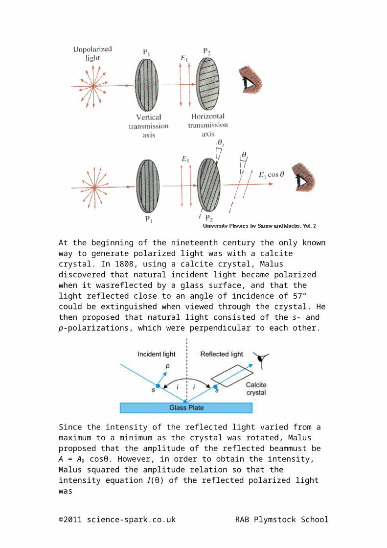
Lesson 26 notes - Malus's LawObjectives(f) explain what is meant by plane polarised waves and understand the polarisation of electromagnetic waves;(g) explain that polarisation is a phenomenon associated with transverse waves only;(h) state that light is partially polarised on reflection; (i) recall and apply Malus’s law for transmitted intensity of light from a polarising filter.
At the beginning of the nineteenth century the only known way to generate polarized light was with a calcite crystal. In 1808, using a calcite crystal, Malus discovered that natural incident light became polarized when it wasreflected by a glass surface, and that the light reflected close to an angle of incidence of 57° could be extinguished when viewed through the crystal. He then proposed that natural light consisted of the s- and p-polarizations, which were perpendicular to each other.
©2011 science-spark.co.uk RAB Plymstock School

Since the intensity of the reflected light varied from a maximum to a minimum as the crystal was rotated, Malus proposed that the amplitude of the reflected beammust be A = A0 cosθ. However, in order to obtain the intensity, Malus squared the amplitude relation so that the intensity equation I(θ) of the reflected polarized light was
where I0 = A02. this equation is known as Malus’s Law. A normalized plot of
Malus’s Law is shown below.
©2011 science-spark.co.uk RAB Plymstock School

Lesson 26 questions – Malus’s Law1. (i) Define the term plane-polarisation of visible light waves.
............................................................................................................
............................................................................................................
[1]
(ii) Explain why sound waves cannot be plane-polarised.
............................................................................................................
............................................................................................................
............................................................................................................
............................................................................................................
[2]
[Total 3 marks]
2. Fig. 1 shows a student observing a parallel beam of plane-polarised light that has passed through a polarising filter.
p lane-polarised light po laro id
eye
Fig. 1
©2011 science-spark.co.uk RAB Plymstock School
(i) Fig. 2 shows how the intensity of the light reaching the student varies as the polarising filter is rotated through 360o in its own plane.
intensity
00 90º 180º 270º 360º
angle o f rotation
Fig. 2
Suggest why there is a series of maxima and minima in the intensity.
...........................................................................................................
............................................................................................................
............................................................................................................
............................................................................................................
[2]
(ii) Hence explain how sunglasses using polarising filters reduce glare.
............................................................................................................
............................................................................................................
............................................................................................................
............................................................................................................
[2]
[Total 4 marks]3. State an example of plane-polarisation that does not involve visible light
©2011 science-spark.co.uk RAB Plymstock School
and state how the polarised wave may be detected.
.....................................................................................................................
.....................................................................................................................
.....................................................................................................................[Total 2 marks]
Lesson 27 notes – InterferenceObjectives(a) state and use the principle of superposition of waves;(b) apply graphical methods to illustrate the principle of superposition;(c) explain the terms interference, coherence, path difference and phase difference;(d) state what is meant by constructive interference and destructive interference;
Interference• When 2 or more waves interact with each other to distort the
waveform of the other(s).
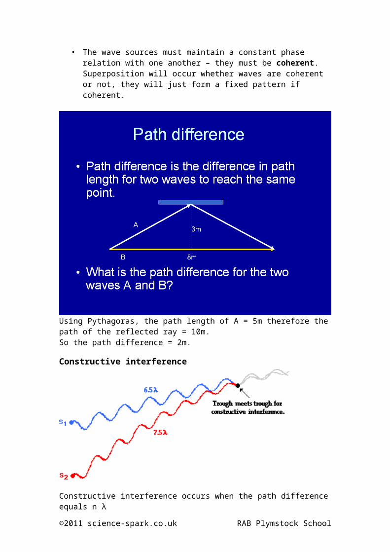
Path difference• Path difference is the difference in path length for two waves to reach
the same point.
SuperpositionThe principle of superposition may be applied to waves whenever two (or more) waves travelling through the same medium at the same time. The waves pass through each other without being disturbed. The net displacement of the medium at any point in space or time, is simply the sum of the individual wave displacements. This is true of waves which are finite in length (wave pulses) or which are continuous sine waves.
Constructive and destructive interferenceWhere a crest meets a crest we get constructive interference (reinforcement)
©2011 science-spark.co.uk RAB Plymstock School
Where a crest meets a trough we get destructive interference
Conditions for interference• The waves must be of similar types! (can’t be light and sound)• The wave sources must maintain a constant phase relation with one
another – they must be coherent. Superposition will occur whether waves are coherent or not, they will just form a fixed pattern if coherent.
Using Pythagoras, the path length of A = 5m therefore the path of the reflected ray = 10m.So the path difference = 2m.
©2011 science-spark.co.uk RAB Plymstock School
Constructive interference
Constructive interference occurs when the path difference equals n λ
Destructive interference
Destructive interference occurs when the path difference equals (n + ½) λ
©2011 science-spark.co.uk RAB Plymstock School

Lesson 28 notes - 2 source interferenceObjectives(e) describe experiments that demonstrate two source interference using sound, light and microwaves;(f) describe constructive interference and destructive interference in terms of path difference and phase difference;(g) use the relationships intensity = power/cross-sectional area and intensity = k x amplitude2 ;
Waves on a pondImagine dropping a pebble into a pond. It would make these kind of concentric circles:
If you dropped 2 pebbles in a pond the waves would interfere with each other like this:
The lines are where there would be destructive interference. In between this there is constructive interference because of the path difference between the waves.
You can imagine that if these two sources were speakers and you walked along the edge you would hear loud and soft sounds. Likewise if they were light waves there would be light and dark areas, these areas are called fringes and will be described in more detail in lesson 29.
©2011 science-spark.co.uk RAB Plymstock School
Two Source Sound InterferenceTwo speakers are set approximately 1 meter apart and produced identical tones.
In the diagram, the compressions of a wavefront are represented by a thick line and the rarefactions are represented by thin lines.
These two waves interfere in such a manner as to produce locations of some loud sounds and other locations of no sound. The loud sounds are heard at locations where compressions meet compressions or rarefactions meet rarefactions and the "no sound" locations appear wherever the compressions of one of the waves meet the rarefactions of the other wave.
So if you slowly walk across the room parallel to the plane of the speakers, you hear loud sounds as you approached anti-nodal locations and virtually no sound as you approached nodal locations. (there would be some because of reflections from the walls)
Young’s Slits Experimenthttp://www.colorado.edu/physics/2000/schroedinger/two-slit2.html
©2011 science-spark.co.uk RAB Plymstock School

Lesson 29 notes - IntensityObjectives(g) use the relationships intensity = power/cross-sectional area and intensity = k x amplitude2 ;
Definition of Intensity
The intensity of any wave is the rate at which it transmits power per unit area through some region of space.
I = PA
The unit of intensity is the watt per square meter — a unit that has no special name.
For waves that radiate in all directions, the intensity goes down as the area covered by the wave goes up. This is called the Inverse Square Law:
Since the intensity is the power / area. As the sound is spread over larger areas, the intensity goes down. You can find the area of a sphere by using the equation 4r2.So the equation for intensity becomes:
I = P4r2
©2011 science-spark.co.uk RAB Plymstock School

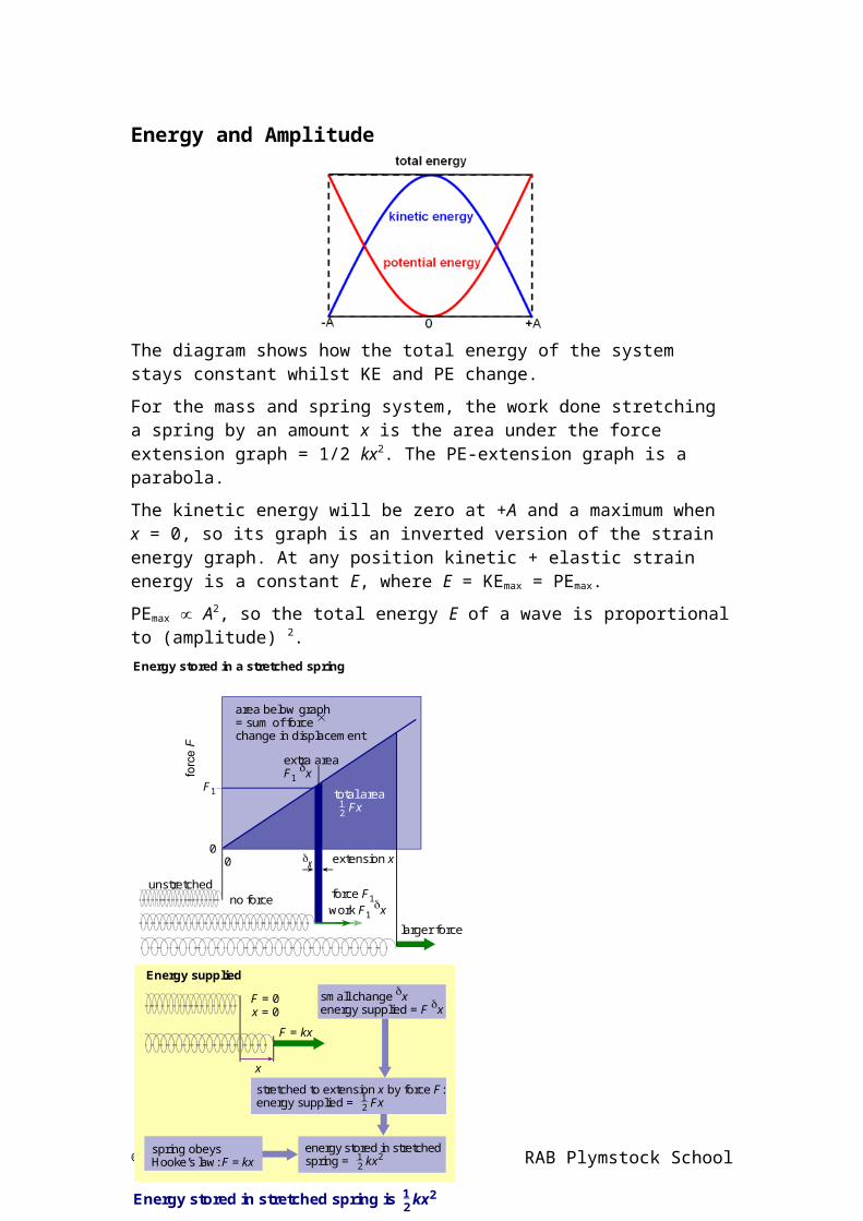
Energy and Amplitude
The diagram shows how the total energy of the system stays constant whilst KE and PE change.
For the mass and spring system, the work done stretching a spring by an amount x is the area under the force extension graph = 1/2 kx2. The PE-extension graph is a parabola.
The kinetic energy will be zero at +A and a maximum when x = 0, so its graph is an inverted version of the strain energy graph. At any position kinetic + elastic strain energy is a constant E, where E = KEmax = PEmax.
PEmax A2, so the total energy E of a wave is proportional to (amplitude) 2.
©2011 science-spark.co.uk RAB Plymstock School
Energy stored in a stretched spring
no forcework F1 xforce F1
x
larger force
extension x
area below graph= sum of force change in displacement
extra areaF1 x
total area Fx2
1
unstretched
F1
Energy supplied
energy stored in stretchedspring = kx2
21
small change xenergy supplied = F x
stretched to extension x by force F:energy supplied = Fx2
1
spring obeysHooke’s law: F = kx
F = 0x = 0
F = kx
Energy stored in stretched spring is kx221
00
x

Since power is the energy transferred in a given time, therefore intensity is also proportional to (amplitude) 2.

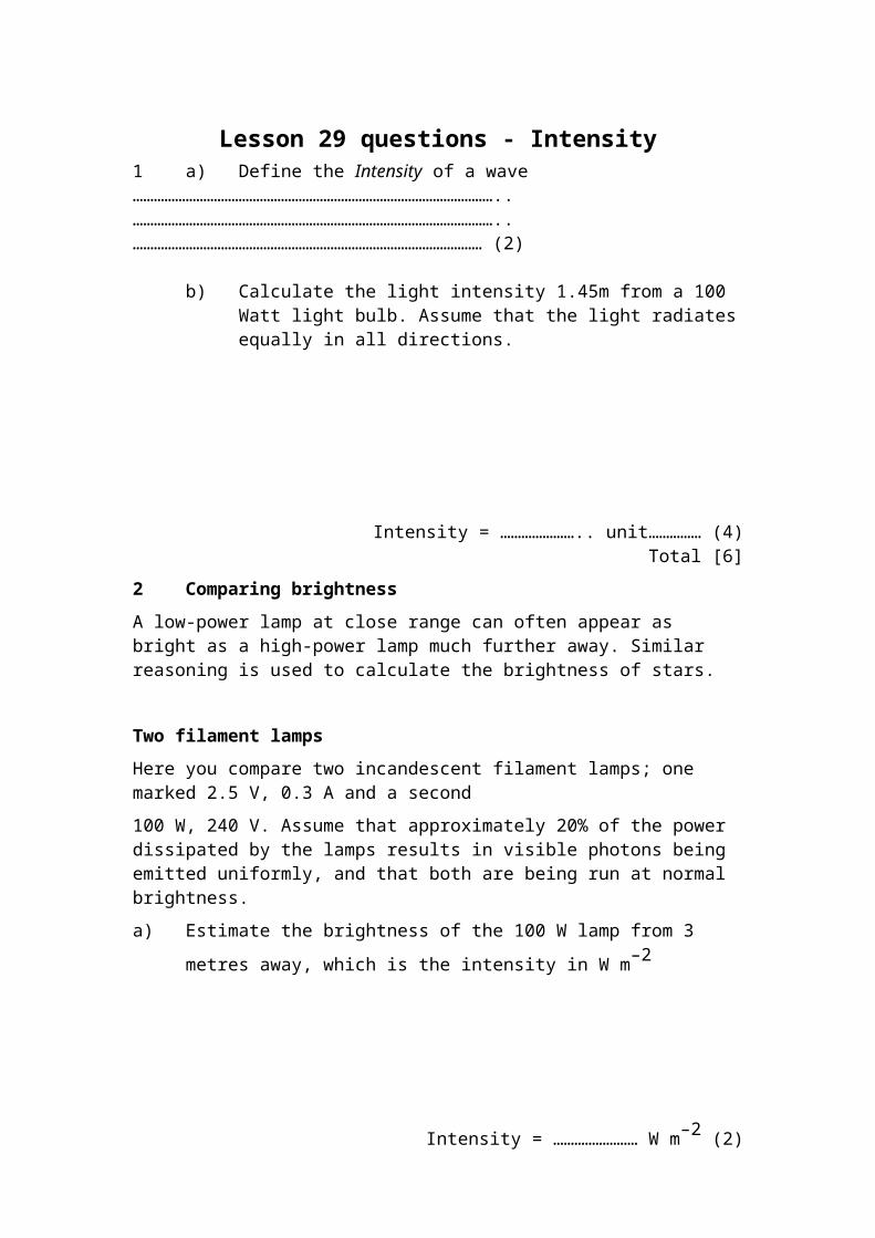
Lesson 29 questions - Intensity1 a) Define the Intensity of a wave…………………………………………………………………………………………..…………………………………………………………………………………………..……………………………………………………………………………………… (2)
b) Calculate the light intensity 1.45m from a 100 Watt light bulb. Assume that the light radiates equally in all directions.
Intensity = ………………….. unit…………… (4)Total [6]
2 Comparing brightness
A low-power lamp at close range can often appear as bright as a high-power lamp much further away. Similar reasoning is used to calculate the brightness of stars.
Two filament lamps
Here you compare two incandescent filament lamps; one marked 2.5 V, 0.3 A and a second
100 W, 240 V. Assume that approximately 20% of the power dissipated by the lamps results in visible photons being emitted uniformly, and that both are being run at normal brightness.
a) Estimate the brightness of the 100 W lamp from 3 metres away, which is the
intensity in W m–2
Intensity = …………………… W m–2 (2)
b) Calculate how close you must be to the 2.5 V lamp to see it as being the same intensity?
Distance = ……………………… m (2)

3 Two floodlights
This question is about a 3 W bicycle headlight and a 300 W exterior security floodlight. Both the floodlight and the headlight have approximately the same shaped beam, a cone that covers approximately 1 / 10 of a sphere.
a) Estimate the intensity of the bicycle lamp from 20 metres away.
Intensity = …………………. W m–2 (3)
b) Your pupil has a diameter of approximately 0.01 m.
What is the power of the light that enters your eyeball per second?
Power =…………………….. Watts (2)
c) The floodlight looks just as bright as the bicycle lamp.
How far away is it?
Distance = …………………….metres (4)Total [10]

Lesson 30 notes – Young’s SlitsObjectives(h) describe the Young double-slit experiment and explain how it is a classical confirmation of the wave-nature of light (HSW 1);(i) Select and use the equationλ = ax D for electromagnetic waves;(j) describe an experiment to determine the wavelength of monochromatic light using a laser and a double slit (HSW 1);
The Wave Nature of light Look at the diagram below. This is Thomas Young’s experiment that he carried out in 1801.
He fired coherent light of one colour towards a screen with two small slits in it. He did this to discover if light was a wave or if it was a particle. If it was a particle it would just form two fringes of light as in the diagram below.
If light was a wave though and the slits were of the right size (about the same size as the wavelength of the light) it would diffract and behave as in the diagram below:
At some points the two sets of waves will meet crest to crest, at other spots crest meets trough. Where crest meets crest, there will be constructive interference and the waves will make it to the viewing screen as a bright spot. Where crest meets trough there will be destructive interference that cancel each other out.
When this experiment is performed what we actually see is shown in the diagram below:
So therefore light must be a wave because particles cannot diffract.

Analysing the experiment
To create the first bright fringe, the path difference of light from slit Q must one wavelength further than light from slit P so that constructive interference occurs.
For small values of the fringe width, x, the two shaded triangles are similar and so a/ λ = D/x.
So rearranging:
λ = ax/D
a
Slit P
Slit Q λD
O
First bright fringe
Screen
x

Lesson 30 questions – Young’s Slits1 Explain what is meant by the principle of superposition of two waves.
.....................................................................................................................
.....................................................................................................................
.....................................................................................................................
.....................................................................................................................[Total 2 marks]
2 (a) A detector is moved in front of two identical coherent wave sources and detects regions of constructive and destructive interference. Explain the terms
(i) coherence..........................................................................................................................................................................................................................................................................[1]
(ii) path difference...........................................................................................................................................................................................................................................................................[1]
(b) Fig. 4.1 shows two identical monochromatic light sources S1 and S2 placed in front of a screen. The sources emit light in phase with each other.
Fig. 4.1(i) State, in terms of the path difference of the waves, the conditions
necessary to produce:
1 constructive interference at point P on the screen..........................................................................................................................................................................................................................................................................[1]
2 destructive interference at point Q on the screen...........................................................................................................................................................................................................................................................................[1]

(ii) The light sources S1 and S2 are 0.50 mm apart. They each emit light of wavelength 4.86 × 10⁻⁷ m. An interference pattern is produced on the screen placed 2.00 m from the sources. Calculate the distance between two neighbouring bright fringes on the screen.
distance = ......................................................m [3](iii) Suggest how the appearance of the interference pattern would change if
coherent white light sources were used instead of the monochromatic sources..................................................................................................................................................................................................................................................................................................................................................................................................................[2]
[Total: 9]
3 (a) In an experiment to try to produce an observable interference pattern, two monochromatic light sources, S1 and S2, are placed in front of a screen, as shown in the diagram below.
aS 1
screen
P
O
y
D
S 2
(i) In order to produce a clear interference pattern on the screen, the light sources must be coherent. State what is meant by coherent.
..................................................................................................
..................................................................................................
..................................................................................................[2]

(ii) In the diagram, the central point O is a point of maximum intensity. Point P is the position of minimum intensity nearest to O. State, in terms of the wavelength λ, the magnitude of the path difference S1P and S2P.
..................................................................................................[1]
(b) In an experiment to try to produce an observable interference pattern, two monochromatic light sources, S1 and S2, are placed in front of a screen, as shown in Fig. 1.
aS 1
screen
P
O
y
D
S 2
Fig. 1
In another experiment, a beam of laser light of wavelength 6.4 × 10⁻⁷ m is incident on a double slit which acts as the two sources in the diagram above.
(i) Calculate the slit separation a, given that the distance D to the screen is1.5 m and the distance between P and O is 4.0 mm.
a = ............................................................ m[3]
(ii) Sketch on the axes of Fig. 2 the variation of the intensity of the light on the screen with distance y from O.
in tensity
–16 –14 –12 –10 –8 –6
–4 –2 0 2 4 6 8 10 12 14 16 /m my0
Fig. 2[2]

[Total 8 marks]
Lesson 31 notes - Diffraction GratingsObjectives(k) describe the use of a diffraction grating to determine the wavelength of light (the structure and use of a spectrometer are not required);(l) select and use the equation dsinθ = nλ;(m) explain the advantages of using multiple slits in an experiment to find the wavelength of light.
IntroductionA diffraction grating is an object that has lots of slits that light can pass through. It can be used to split white light up into a spectrum.
Multiple slits
If the path difference is exactly 1 wavelength like in the diagram they will constructively interfere to produce a bright fringe. From the diagram you can see that this happens when: (/d)=sin. If the path difference is just slightly out then destructive interference will occur and no light will be seen. So if white light is shone through dispersion occurs. A spectrum of fringes will be seen as below with white in the centre where the path difference in zero, violet nearest the centre and red nearest the edge:
Measuring the wavelength of monochromatic light
So this is what you would see on a screen. An undeviated central maximum and then dark and light fringes because of constructive and destructive interference.
The maxima occur because the path difference is equal to a number of wavelengths, ie, 2, 3, etc, rather than just . The number of the maximum is called the order of maximum, n.
So from above and rearranging, we get:
n=dsinn.
undeviated light. central maximum zeroth order
n=1 1st order maximum
n=1 1st order maximum
n=2 2nd order maximum
n=2 2nd order maximum
n=3 3rd order maximum
n=3 3rd order maximum
Monochromatic source
Diffraction grating

Lesson 31 questions – Diffraction Gratings
These questions give you practice in using the grating formula n = d sin n.
A grating is labelled '500 lines per mm'.
1. Calculate the spacing of the slits in the grating.
2. Monochromatic light is aimed straight at the grating and is found to give a first-order maximum at 15º. Calculate the wavelength of the light source.
3. Calculate the position of the first-order maximum when red light of wavelength
730 nm is shone directly at the grating.
4. The longest visible wavelength is that of red light with = 750 nm. The shortest visible wavelength is violet where = 400nm. Use this information to calculate the width of the angle into which the first-order spectrum is spread out when white light is shone onto the grating.
A grating is illuminated with a parallel beam of light of wavelength 550 nm. The first-order maximum is in a direction making an angle of 20º with the straight-through direction.
5. Calculate the spacing of the grating slits.
6. What would be the angle of the first-order maximum if a grating of slit spacing of
2.5 10–6 m were used with the same light source?
7. Calculate the wavelength of light that would give a second-order maximum at = 32º
with a grating of slit spacing 2.5 10–6 m.
Hints1. What must the gap be between the centre of each line in order to fit 500 lines into
1 mm? Remember to express your answer in metres.
2. This is about the first-order minimum so use the formula n = d sin with n = 1.
3. Rearrange the formula n = d sin to make sin the subject. Remember to take the arcsin (or sin–1) to give an answer in degrees.
4. Use the same method as question 3 to obtain the position of first-order maxima for red and violet light. The dispersion is simply the angle of maximum of red light minus the angle of maximum of violet light.

Lesson 31 notes – Stationary WavesObjectives2.4.4 Stationary wavesCandidates should be able to:(a) explain the formation of stationary (standing) waves using graphical methods;(b) describe the similarities and differences between progressive and stationary waves;(c) define the terms nodes and antinodes;
Stationary (Standing) WavesStationary waves occur when two progressive waves of the same wavelength and frequency interfere constructively to produce a wave pattern that seems to oscillate about fixed points.
This can be two waves from different sources or as the diagram below shows, can be from one source and its reflected wave.
Nodes and AntinodesThe diagram shows that nodes are positions where there is complete destructive interference while at antinodes there is complete constructive interference.

Lesson 32 notes – stationary waves and resonanceObjectives(d) describe experiments to demonstrate stationary waves using microwaves, stretched strings and air columns;(e) determine the standing wave patterns for stretched string and air columns in closed and open pipes;(f) use the equation: separation between adjacent nodes (or antinodes) = λ/2;(g) define and use the terms fundamental mode of vibration and harmonics;(h) determine the speed of sound in air from measurements on stationary waves in a pipe closed at one end.
Guitar StringsA guitar string has a number of frequencies at which it will naturally vibrate. These natural frequencies are known as the harmonics of the guitar string and are associated with a standing wave pattern.
The diagram below depicts the standing wave patterns for the lowest three harmonics or frequencies of a guitar string.
The wavelength of the standing wave for any given harmonic is related to the length of the string.
The first harmonic is sometimes called the fundamental mode because it is the simplest wave that can be formed.
Harmonic Pattern # of LoopsLength-Wavelength
Relationship
1st 1 L = 1 / 2 •
2nd 2 L = 2 / 2 •
3rd 3 L = 3 / 2 •

4th 4 L = 4 / 2 •
5th 5 L = 5 / 2 •
6th 6 L = 6 / 2 •
nth-- n L = n / 2 •
Standing waves in a pipe closed at one end
We can do the same as above for a resonating tube and be able to find wavelength or length of tube given the other and the harmonic.
Harmonic Pattern
Length of resonating air (L) -Wavelength
Relationship
1st L = (1 / 4) •
2nd L = (3 / 4) •
3rd L = (5 / 4) •
nth -- L = (2n-1) / 4 •

Substituting in v=f into allow us to work out the speed of sound if we know the resonating frequency.
Resonating column with one end closed
Apparatus Resonance Tube (eg perspex tube, about 75 cm long and about 5 cm internal diameter), loudspeaker with similar diameter (0.1 W, higher impedance better for typical oscillator), oscillator (preferably matching loudspeaker power rating/impedance or low impedance audio amplifier may be necessary), tie clip microphone/preamp, oscilloscope, thermometer, two test leads (BNC - 4 mm). The schematic experimental set up is as shown in figure 2.
Figure 2
Setting up the apparatus Set up the resonance tube, microphone, oscillator and oscilloscope as
shown in figure 1. Remove the piston from the tube and ensure the microphone is
mounted in the Resonance Tube. Connect the low impedance (50 W or less) output of the oscillator to
the loudspeaker (32 W) and to channel one on the oscilloscope. Connect the microphone output to channel two on the oscilloscope. Switch on the microphone amplifier (remember to switch off the
microphone amplifier at the end of the laboratory period). Trigger the oscilloscope on the signal going to the loudspeaker
(channel one). Set the oscillator to approximately 100 Hz and adjust the amplitude
until the sound from the speaker can be heard. Adjust the oscilloscope to show two steady signals, if you have any
difficulties consult one of the staff running the laboratory.

Experiment
Closed Tube Method Insert the piston into the tube so that the tube length is now between 0.50 and 0.70 m.Set the oscillator frequency to about 1 kHz and then adjust the oscillator to obtain a resonance. Move the microphone along the tube, make a note of the positions where the signal reaches a maximum and a minimum. Sketch the wave amplitude along the tube. Mark on your sketch nodes, antinodes and their positions. Make sure you mark the open and closed ends of the tube on your sketch. Does your sketch agree with the displacement amplitude patterns for the closed tube shown in figure 1? Which overtone/harmonic does you sketch show? The separation between adjacent nodes (weakest signal) and between adjacent antinodes (strongest signal) is equal to l/2 where is the wavelength. Calculate several times from your data. Measure the frequency of the resonance using the oscilloscope. Calculate the speed of sound using v = fl , how does this compare with your previous value?

Lesson 32 questions – Stationary waves and resonance
1. State and explain one difference between a progressive and a standing wave.
.....................................................................................................................
.....................................................................................................................
.....................................................................................................................[Total 2 marks]
2. (a) In an investigation of standing waves, a loudspeaker is positioned
above a long pipe containing water, causing sound waves to be sent down the pipe. The waves are reflected by the water surface. The water level is lowered until a standing wave is set up in the air in the pipe as shown in Fig. 1. A loud note is heard. The water level is then lowered further until a loud sound is again obtained from the air in the pipe. See Fig. 2.
l1
c
water
pipe
l2
c
water
pipe
Fig. 1 Fig. 2
The air at the open end of of the pipe is free to move and this means that the antinode of the standing wave is actually a small distance c beyond the open end. This distance is called the end correction.
A student writes down the following equations relating the two situations shown.
l1 + c = λ/4 l2 + c = 3λ/4
(i) Draw the standing wave in the pipe shown in Fig. 2 which corresponds to the equation l2 + c = 3λ/4.
[1]
(ii) On your diagram, label the positions of any displacement nodes and antinodes with the letters N and A respectively.
[1]
(iii) Use the two equations to show that l1 – l2 = λ/2.
[1]
(iv) The following results were obtained in the experiment.
frequency of sound = 500Hz l1 = 0.170 m l2 = 0.506 m
Calculate the speed of sound in the pipe.
speed = ………………..m s–1
[3]
(b) The student repeats the experiment, but sets the frequency of the sound from the speaker at 5000 Hz.
Suggest and explain why these results are likely to give a far less accurate value for the speed of sound than those obtained in the first experiment.
In your answer, you should make clear the sequence of steps in your argument.
............................................................................................................
............................................................................................................
............................................................................................................
............................................................................................................
............................................................................................................
...........................................................................................................

.Total [10 marks]