Embed Size (px)
Citation preview

1May 2004
Length Gauges

2
Incremental length gauges from
HEIDENHAIN offer high accuracy over long measuring ranges. These sturdily made gauges are available in application-oriented versions.
They have a wide range of applications in production metrology, in multipoint inspection stations, measuring equipment monitoring, and as position measuring devices.
This catalog supersedes all previous editions, which thereby become invalid.The basis for ordering from HEIDENHAIN is always the catalog edition valid when the contract is made.
Standards (ISO, EN, etc.) apply only where explicitly stated in the catalog.

3
Length Gauges—Applications and Products
Range of Applications, Application Examples 4
Length Gauges from HEIDENHAIN 6
Length Gauge Overview 8
Technical Features and Mounting Information
Functional Principle 10
Mechanical Design 11
Measuring Accuracy 12
Gauging Force and Plunger Actuation 14
Mounting 16
Specifi cations Accuracy Measuring range
HEIDENHAIN-CERTO ± 0.1 µm; ± 0.03 µm*± 0.1 µm; ± 0.05 µm*
25 mm 60 mm
18
HEIDENHAIN-METRO ± 0.2 µm 12 mm 25 mm
20
HEIDENHAIN-METRO ± 0.5 µm± 1 µm
60 mm100 mm
22
HEIDENHAIN-SPECTO ± 1 µm 12 mm 30 mm
24
Length Gauge Accessories
Measuring Contacts, Switch Boxes, Coupling 26
Gauge Stands, Ceramic Suction
Plate, Diaphragm Compressor
for HEIDENHAIN-CERTO 28
Cable-Type Lifter, Gauge Stands for HEIDENHAIN-METRO and HEIDENHAIN-SPECTO
30
Evaluation and Display Units
Measured Value Display Units 32
Counter Cards 35
Electrical Connection
Interfaces Incremental signals » 1 VPP 36
Incremental signals « TTL 38
Incremental signals » 11 µAPP 40
Connecting Elements and Cables 41
* After linear length-error compensation in the evaluation electronics
4
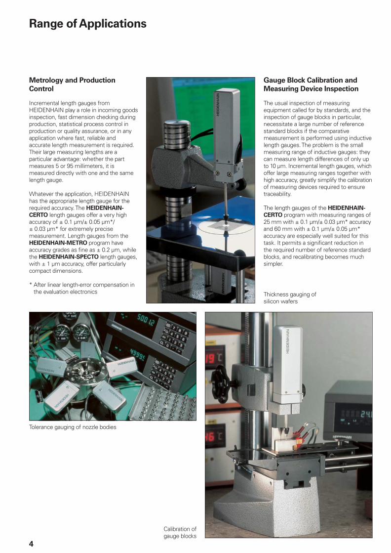
Range of Applications
Metrology and Production
Control
Incremental length gauges from HEIDENHAIN play a role in incoming goods inspection, fast dimension checking during production, statistical process control in production or quality assurance, or in any application where fast, reliable and accurate length measurement is required. Their large measuring lengths are a particular advantage: whether the part measures 5 or 95 millimeters, it is measured directly with one and the same length gauge.
Whatever the application, HEIDENHAIN has the appropriate length gauge for the required accuracy. The HEIDENHAIN-
CERTO length gauges offer a very high accuracy of ± 0.1 µm/± 0.05 µm*/± 0.03 µm* for extremely precise measurement. Length gauges from the HEIDENHAIN-METRO program have accuracy grades as fi ne as ± 0.2 µm, while the HEIDENHAIN-SPECTO length gauges, with ± 1 µm accuracy, offer particularly compact dimensions.
* After linear length-error compensation in the evaluation electronics
Gauge Block Calibration and
Measuring Device Inspection
The usual inspection of measuring equipment called for by standards, and the inspection of gauge blocks in particular, necessitate a large number of reference standard blocks if the comparative measurement is performed using inductive length gauges. The problem is the small measuring range of inductive gauges: they can measure length differences of only up to 10 µm. Incremental length gauges, which offer large measuring ranges together with high accuracy, greatly simplify the calibration of measuring devices required to ensure traceability.
The length gauges of the HEIDENHAIN-
CERTO program with measuring ranges of 25 mm with ± 0.1 µm/± 0.03 µm* accuracy and 60 mm with ± 0.1 µm/± 0.05 µm* accuracy are especially well suited for this task. It permits a signifi cant reduction in the required number of reference standard blocks, and recalibrating becomes much simpler.
Thickness gauging of silicon wafers
Tolerance gauging of nozzle bodies
Calibration of gauge blocks

5
Multipoint Inspection Devices
Multipoint inspection devices require durable length gauges with small dimensions. They should also have relatively large measuring ranges of several millimeters with consistent linear accuracy in order to simplify the construction of inspection devices—for example by enabling the construction of one device for several masters. A large measuring length also provides benefi ts in master production, because simpler masters can be used.
With their small dimensions and measuring ranges of 12 mm or 30 mm and ± 1 µm accuracy, the HEIDENHAIN-SPECTO incremental length gauges are specifi cally designed for multipoint inspection devices. Higher accuracy requirements up to ± 0.2 µm can be met with similarly compact HEIDENHAIN-METRO length gauges.
Unlike inductive gauges, HEIDENHAIN-SPECTO length gauges provide stable measurement over long periods—eliminating recalibration.
Position Measurement
Incremental length gauges from HEIDENHAIN are also ideal for position measurement on precision linear slidesor X-Y tables. Working with measuring microscopes, for example, becomes much easier thanks to the digital readout and the fl exible datum setting.
Here, length gauges from the HEIDENHAIN-METRO and HEIDENHAIN-
SPECTO program come into use with large measuring ranges of 30 mm, 60 mm or 100 mm at consistently high accuracy grades of ± 0.5 µm or ± 1 µm.
In this application as linear measuring device, the length gauge’s fast installation in accordance with the Abbe measuring principle by its clamping shank or planar mounting surface is of special benefi t.
Inspection station inspark plug manufacture
Measuring the error of linear guides
Position measurement on a microscope with X-Y table and
adjustable height

6
Length Gauges from HEIDENHAIN
High accuracyThe high accuracy specifi ed for HEIDENHAIN length gauges applies over the entire measuring length. Whether the part measures 10 or 100 mm, its actual dimension is always measured with the same high quality. The high repeatability of HEIDENHAIN length gauges comes into play during comparative measurements, for example in series production.
A number of arguments speak for HEIDENHAIN length gauges. These include not only their technical features, but also their high quality standard and the worldwide presence of HEIDENHAIN.
Large measuring rangesHEIDENHAIN length gauges are available with measuring lengths of 12 mm, 25 mm, 30 mm, 60 mm or 100 mm. so that you can measure very different parts in one measuring setup and avoid frequently changing setups with expensive gauge blocks or masters.
Robust designHEIDENHAIN length gauges are built for an industrial environment. They feature consistently high accuracy over a long period of time as well as high thermal stability. They can therefore be used in production equipment and machines.

7
Wide range of applicationsHEIDENHAIN length gauges are suited for many applications. Automatic inspection equipment, manual measuring stations or positioning equipment—wherever lengths, spacing, thickness, height or linear motion are to be measured, HEIDENHAIN length gauges function quickly, reliably and accurately.
Know-howThe high quality of HEIDENHAIN length gauges is no coincidence. HEIDENHAIN has been manufacturing high-accuracy scales for over 70 years, and for many years it has developed measuring and testing devices for length and angle measurement for national standards laboratories. This know-how makes HEIDENHAIN an extraordinarily qualifi ed partner for metrological questions.
Worldwide presenceHEIDENHAIN is represented in all important industrial countries—in most of them with wholly owned subsidiaries. Sales engineers and service technicians support the user on-site with technical information and servicing in the local language.

8
Length Gauge Overview
Accuracy Measuring range
± 0.1 µm
± 0.05 µm*)
± 0.03 µm*)
HEIDENHAIN-CERTO
Plunger actuationby motor
Motor-driven or by external coupling
± 0.2 µm HEIDENHAIN-METRO
Plunger actuation by cable lifter or measured object
Pneumatic plunger actuation
± 0.5 µm
± 1 µm
HEIDENHAIN-METRO
Plunger actuationby motor
Motor-driven or by external coupling
± 1 µm HEIDENHAIN-SPECTO
Plunger actuation by measured object
Pneumatic plunger actuation
*) After linear length-error compensation in the evaluation electronics
MT 101 MT 60 MT 2500 MT 1200

9
12 mm 25 mm/
30 mm
60 mm 100 mm Page
18
CT 2501 » 11 µAPP
CT 2502 » 11 µAPP
CT 6001 » 11 µAPP
CT 6002 » 11 µAPP
20
MT 1201 » 11 µAPPMT 1271 « TTLMT 1281 » 1 VPP
MT 1287 » 1 VPP
MT 2501 » 11 µAPPMT 2571 « TTLMT 2581 » 1 VPP
MT 2587 » 1 VPP
22
MT 60M » 11 µAPP
MT 60K » 11 µAPP
MT 101M » 11 µAPP
MT 101K » 11 µAPP
24
ST 1208 » 11 µAPPST 1278 « TTLST 1288 » 1 VPP
ST 1207 » 11 µAPPST 1277 « TTLST 1287 » 1 VPP
ST 3008 » 11 µAPPST 3078 « TTLST 3088 » 1 VPP
ST 3007 » 11 µAPPST 3077 « TTLST 3087 » 1 VPP
CT 6000 CT 2500 ST 3000 ST 1200

10
Functional Principle
HEIDENHAIN length gauges are characterized by long measuring ranges and consistently high accuracy. The basis for both is the measuring principle of photoelectrically scanning an incremental scale.
HEIDENHAIN linear encoders use material measuring standards consisting of incremental graduations on substrates of glass or glass ceramic. These measuring standards permit large measuring ranges, are insensitive to vibration and shock, and have a defi ned thermal behavior. Changes in atmospheric pressure or relative humidity have no infl uence on the accuracy of the measuring standard—which is the prerequisite for the high long-term
stability of HEIDENHAIN length gauges.
The masters for these graduations are fabricated on dividing engines developed and built by HEIDENHAIN. High thermal stability during the manufacturing process ensures that the graduations have high
accuracy over the measuring length. The master graduation is applied to the carrier using the DIADUR copying processes developed by HEIDENHAIN, which produces very thin but durable graduation structures of chromium.
The incremental graduation is photoelectrically scanned without mechanical contact and therefore without wear. Light passes through the structured scanning reticle and over the scale onto photovoltaic cells. The photovoltaic cells produce sinusoidal output signals with a small signal period (see page 36). Inter-polation in the subsequent electronics makes very small measuring steps into the nanometer range possible. The scanning principle, together with the extremely fi ne graduation lines and their high edge defi nition ensure the quality of the output signals as well as the small position error within
one signal period. This applies particularly to HEIDENHAIN length gauges, which use a DIADUR phase grating as measuring standard. The interferential scanning method produces sinusoidal incremental signals with a period of only 2 µm.
Reference mark
Photoelectric scanning of grid structures results in an incremental, i.e. counting, measurement. To ascertain positions, an absolute reference is required. The reference mark enables the exact reestablishmentof the most recently defi ned datum, for example after an interruption in power. It is photoelectrically scanned and is permanently associated with exactly one measuring step, regardless of the direction or velocity of traverse.
DIADUR phase grating with approx. 0.25 µm grating height
Grating period
Carrier
Reference mark
Incremental graduation
DIADUR graduation
5 µm

11
Mechanical Design
HEIDENHAIN length gauges function according to the Abbe measuring principle, i.e. the measuring standard and the plunger are exactly aligned. All components comprising the measuring loop, such as the measuring standard, plunger, holder and scanning head are designed in terms of their mechanical and thermal stability for the highest possible accuracy of the length gauge.
HEIDENHAIN length gauges feature adefi ned thermal behavior. Since tempera-ture variations during measurement canresult in changes in the measuring loop, HEIDENHAIN uses special materials with low Þtherm coeffi cients of expansion for the components of the measuring loop, forexample in the CERTO length gauges. The scale is manufactured of ZERODUR® (Þtherm � 0 K–1), and the plunger and holder are of Invar (Þtherm � 1 · 10–6 K–1). This makes it possible to guarantee its high measuring accuracy over a relatively large temperature range.
Length gauges from HEIDENHAIN feature a sturdy design. Even high vibration and shock loads have no negative infl uence on the accuracy documented in the calibration chart.
The ball-bush guided plunger tolerates high radial forces and moves with very low friction. It has an M2.5 thread to hold measuring contacts.
Expendable parts
HEIDENHAIN length gauges contain components that are subject to wear, depending on the application and manipulation. These include in particular the following parts:
LED light sourceGuideway (tested for at least 5 million strokes*)Cable link for CT, MT 60 and MT 101 (tested for at least 1 million strokes*)Scraper ringsRubber bellows on ST
* On CT, MT 60M and MT 101M only with actuation by switch box
••
•
••
Design of ST 1200
Encoder cable
Measuring standard
Scanning unit with light source, photocells and scanning electronics
Ball-bush guide
Plunger
Rubber bellows
Measuring contact
Design of CT 6000
MT 60
Measuring standard(scale)
Holder
Scanning unit with light source and photoelements
Ball-bush guide
Plunger
Measuring contact

���
12
Measuring Accuracy
The accuracy of position measurement with length gauges is mainly determined by the following factors:
The quality of the graduationThe quality of the scanning processThe quality of the signal processing electronicsThe error from the scale guideway over the scanning unit
A distinction is made between position error over relatively large paths of traverse—for example the entire measuring range—and that within one signal period.
•••
•
Position error over the measuring range
Length gauge accuracy is specifi ed as system accuracy, which is defi ned as follows:The extreme values of the total error F —with reference to their mean value—lie over the entire measuring length within the system accuracy ± a. They are measured during the fi nal inspection and documented in the calibration chart.
Position error within one signal period
The position error u within one signal period is determined by the signal periodof the length gauge, as well as the quality of the graduation and the scanning thereof. At any position over the entire measuring length, it does not exceed approx. ± 1 %of the signal period. The smaller the signal period, the smaller the position error within one signal period. In the calibration chartof the HEIDENHAIN-CERTO, this position error within one signal period is shown asa tolerance band.
Signal period of the
scanning signals
Max. position error u within
one signal period
CT 2500
CT 6000
2 µm Approx. 0.02 µm
MT 1200
MT 2500
2 µm Approx. 0.02 µm
MT 60
MT 101
10 µm Approx. 0.1 µm
ST 1200
ST 3000
20 µm Approx. 0.2 µm
Position error F over the measuring length ML
Po
sit
ion
err
or �
Position error within
one signal period
Position �
Position error u within one signal period
Signal period
360 °elec.
Sig
nal le
vel �
Po
sit
ion
err
or �

13
All HEIDENHAIN length gauges are inspected before shipping for accuracy and proper function.
They are calibrated for accuracy during retraction and extension of the plunger. For the HEIDENHAIN-CERTO, the number of measuring positions is selected to ascertain very exactly not only the long-range error, but also the position error within one signal period.
The manufacturer’s inspection certifi cate
confi rms the specifi ed system accuracy of each length gauge. The calibration
standards ensure the traceability—as required by ISO 9001—to recognized national or international standards.
For the length gauges of the HEIDENHAIN-METRO and HEIDENHAIN-CERTO series, a calibration chart documents the position error over the measuring range and also states the measuring step and measuring uncertainty of the measurement.
Temperature range
The length gauges are inspected at a reference temperature of 20 °C. The system accuracy given in the calibration chart applies at this temperature.The operating temperature indicates the ambient temperature limits betweenwhich the length gauges will function properly. The storage temperature range of –20 °C to 60 °C applies for the devicein its packaging.

� �
14
Measuring range [mm]
Gauging Force—Plunger Actuation
Gauging force
Gauging force is the force that the plunger exercises on the measured object. An excessively large gauging force can cause deformation of the measuring contact and the measured object. If the gauging force is too small, an existing dust fi lm or other obstacle may prevent the plunger from fully contacting the measured object. The gauging force depends on the type of plunger actuation.
Plunger actuation by spring
For the MT 12x1, MT 25x1, ST 12x8 and ST 30x8, the integral spring extends the plunger to the measuring position and applies the gauging force. In its resting position, the plunger is extended. The gauging force depends on the following criteria:
The operating attitudeThe plunger position, because the gauging force changes over the measuring rangeThe measuring direction, i.e., whether the gauge measures with extending or retracting plunger
There are several ways of actuating the length gauge plunger:
••
•
Plunger actuation by measured object
The complete length gauge is moved relative to the measured object. The measurement is made with retracting plunger.
Plunger actuation by cable-type lifter
Through a cable mechanism, the plunger is retracted by hand and then extended onto the measured object. The measurement is made with extending plunger.
HEIDENHAIN-METRO MT 12x1
HEIDENHAIN-SPECTO ST 12x8
Gau
gin
g fo
rce F
[N
]
1) Plunger retraction2) Plunger extension

�
��
15
Pneumatic plunger actuation
The pneumatically actuated plungers of the MT 1287, MT 2587, ST 12x7 and ST 30x7 length gauges are extended by the application of compressed air. When the air connection is ventilated, the integral spring retracts the plunger to a protected resting position within the housing.
The gauging force can be adjusted to the measuring task through the level of air pressure. At constant pressure, it depends on the operating attitude and the plunger position.
The vertically downward position with retracted plunger, for example, has the greatest gauging force, and the vertically upward position with extended plunger the lowest. The data given in the specifi cations are approximate and are subject to variation due to tolerances and to wear in the seal.
The length gauges with pneumatic plunger actuation are particularly well suited for automated measuring systems.
Motorized plunger actuation
The CT 2501, CT 6001, MT 60M and MT 101M length gauges feature an integral motor that moves the plunger. It is operated through the switch box either by push button or over the connection for external operation. The plungers of the CT 2501, CT 6001, and MT 60M length gauges must not be moved by hand if the switch box is connected.
The gauging force of the CT 2501, CT 6001 and MT 60M motorized length gauges is adjustable in three stages through the switch box. The force remains constant over the measuring range but depends on the operating attitude.Regardless of the operating attitude—whether it measures vertically downward (with the SG 101V switchbox) or horizontally (with the SG 101H switch box)—the MT 101M exercises a constant gauging force.
External plunger actuation by coupling
For the CT 2502, CT 6002, MT 60K, MT 101K and special versions (without spring) of the MT 1200 and MT 2500, the plunger is freely movable. For position measurement, the plunger is connectedby a coupling with a moving machine element. The force needed to move the plunger is specifi ed as the required moving force. It depends on the operating attitude.

16
Mounting
In addition to the length gauge itself, the mechanical design of the measuring setup also plays a role in defi ning the quality of measurement.
Abbe principle
HEIDENHAIN length gauges enable you to work according to the Abbe measuring principle: The measured object and scale must be in alignment to avoid additional measuring error.
Measuring loop
All components included in the measuring loop such as the holder for the measured object, the gauge stand with holder, and the length gauge itself infl uence the result of measurement. Expansion or deformation of the measuring setup through mechanical or thermal infl uences adds directly to the error.
Mechanical design
A stable measuring assembly must be ensured. Long lateral elements within the measuring loop are to be avoided. HEIDENHAIN offers a stable gauge stand as an accessory.
The force resulting from the measurement must not cause any measurable deformation of the measuring loop.Incremental length gauges from HEIDENHAIN operate with small gauging force and have very little infl uence on the measuring setup.
Thermal behavior
Temperature variations during measurement cause changes in length or deformation of the measuring setup. After a change in temperature of 5 K, a steel bar of 200 mm length expands by 10 µm.Length changes resulting from a uniform deviation from the reference temperature can largely be compensated by resetting the datum on the measuring plate or a master; only the expansion of the scale and measured object go into the result of measurement. Temperature changes during measurement cannot be ascertained mathematically.
For critical components, HEIDENHAIN therefore uses special materials with low coeffi cients of expansion, such as are found in the HEIDENHAIN-CERTO gauge stand. This makes it possible to guarantee the high accuracy of HEIDENHAIN-CERTO even at ambient temperatures of 19 to 21 °C and variations of ± 0.1 K during measurement.
Thermally induced length change:
Expansion of the measuring loop components as a result of heat
Acceleration
Shock and vibration of any kind is to be avoided during measurement so as not to impair the high accuracy of the length gauge. The maximum values given in the specifi cations apply to the effect of external acceleration on the length gauge. They describe only the mechanical stability of the length gauge, and imply no guarantee of function or accuracy.
In the length gauge itself, unchecked extension of the spring-driven or non-coupled moving plunger can cause high acceleration onto the measured object or measuring plate surface. For the MT 1200 and MT 2500 series length gauges, use the cable-type lifter whenever possible (see Accessories). The cable lifter features adjustable pneumatic damping to limit the extension velocity to an uncritical value.
The measuring loop:
All components involved in the measuring assembly, including the length gauge

�����
���
�����
����
��
�
�
�� ��
17
Fastening
The CT 6000, MT 60 and MT 101 length gauges are fastened by two screws onto a plane surface. This ensures a mechanically stable installation of even these large length gauges. Special holders are available for fastening the MT 60 and MT 101 to the MS 100 gauge stand for the HEIDENHAIN-METRO (see Accessories).
The CT 2500 is mounted by its standard clamping shank with 16h8 diameter.A holder is available for fastening the HEIDENHAIN-CERTO to the gauge stand (see Accessories).
The ST, MT 1200 and MT 2500 length gauges feature a standard clamping shank with 8h6 diameter. These HEIDENHAIN length gauges can therefore easily be used with existing measuring fi xtures and stands.
As an accessory, HEIDENHAIN offers a special clamping sleeve and screw. It facilitates fastening the length gauge securely without overstressing the clamping shank.Clamping sleeve ID 386811-01
Orthogonal mounting
The length gauge is to be mounted so that its plunger is exactly orthogonal to the measured object or the surface on which it rests. Deviations result in error.
The accessory HEIDENHAIN gauge stands with holders for an 8 mm clamping shank ensure orthogonal mounting. Length gauges that provide planar mounting
surfaces are to be adjusted in the direction parallel to the mounting surface (Y) to be perpendicular to the measuring plate. A quick and reliable adjustment is possible with the aid of a gauge block or a parallel block. The perpendicularity to the measuring table (X) is already ensured by the gauge stand.
CT 6000
MT 60
MT 101
CT 2500

���������� ������� ����������������������������
�
��������
18
HEIDENHAIN-CERTO
Length Gauges with ± 0.1 µm/± 0.05 µm*/± 0.03 µm* AccuracyFor very high accuracy
For inspection of measuring equipment and gauge blocks
•
•
HEIDENHAIN-CERTO length gauges feature a large measuring range, provide high linear accuracy and offer resolution in the nanometer range. They are used predominantly for production quality control of high-precision parts and for the monitoring and calibration of reference standards. Length gauges reduce the number of working standards required to calibrate gauge blocks.
Accuracy
The total error of HEIDENHAIN-CERTO length gauges lies within ± 0.1 µm. After linear length error compensation in the evaluation electronics of the ND 281B, for example, HEIDENHAIN guarantees accuracy of ± 0.03 µm for the CT 2500 and ± 0.05 µm for the CT 6000. These accuracy grades apply over the entire measuring range at ambient temperatures between 19 and 21 °C and with a temperature variation of ± 0.1 K during measurements using the CS 200 gauge stand for HEIDENHAIN-CERTO.
Plunger actuation
The plunger of the CT 2501 and CT 6001 is extended and retracted by an integral motor. It can be actuated by the associated switch box, which can also be controlled by external signal. The CT 2502 and CT 6002
have no plunger drive. The freely movable plunger is connected by a separate coupling with the moving machine element.
Mounting
The CT 2500 length gauge is fastened by its 16-mm diameter clamping shank. The CT 6000 is fastened with two screws on a plane surface. The CS 200 gauge stand (see Accessories) was conceived specially for HEIDENHAIN-CERTO length gauges. It fulfi lls the requirements of high precision measurement with respect to thermal behavior, stability, orthogonality and fl atness of the measuring plate surface. A special holder is available as an accessory for mounting the CT 2500.
Output signals
The HEIDENHAIN-CERTO length gauges provide » 11 µAPP current signals for HEIDENHAIN subsequent electronics.
* After linear length-error compensation in the evaluation electronics
r = Reference mark position
mm
CT 2500
CT 6000

19
Specifi cations CT 2501
CT 6001
CT 2502
CT 6002
Plunger actuation Motorized Plunger connected via separate coupling with moving machine part
Measuring standard DIADUR phase grating on Zerodur® glass ceramicGrating period 4 µm
System accuracy
at 19 to 21 °C CT 2500 CT 6000
± 0.1 µm without compensation;± 0.03 µm after linear length error compensation± 0.05 µm after linear length error compensation
Recommd. meas. step 0.01 µm/0.005 µm (5 nm) with ND 281B
Reference mark Approx. 1.7 mm below upper stop
Meas. range CT 2500 CT 6000
25 mm60 mm
Gauging force
Vertically downwardVertically upwardHorizontal
1 N/1.25 N/1.75 N– /– /0.75 N– /0.75 N/1.25 N
–
Required moving force – 0.1 N to 0.6 N (depending on the operating attitude)
Permissible radial force † 0.5 N
Operating attitude Any
Vibration 55 to 2000 HzShock 11 ms
† 100 m/s2 (IEC 60068-2-6)† 1000 m/s2 (IEC 60068-2-27)
Protection IEC 60529 IP 50
Operating temperature 10 to 40 °C; ref. temperature 20 °C
Fastening CT 2500 CT 6000
Clamping shank ¬ 16h8Plane surface
Weight CT 2500without cable CT 6000
520 g700 g
480 g640 g
Incremental signals » 11 µAPP; signal period 2 µm
Measuring velocity † 24 m/min (depending on the subsequent electronics)† 12 m/min with the ND 281B measured value display unit
Electrical connection
Cable length
Cable 1.5 m with M23 connector (male) 9-pin;Interface electronics integrated in connector† 30 m with HEIDENHAIN cable
Power supply 5 V ± 5 %/< 180 mA 5 V ± 5 %/< 120 mA
Required accessories For CT 2501 For CT 6001
Switch box SG 25MID 317436-01
SG 60MID 317436-02
CT 2500
CT 6000

�����
����� ��������� � �
���
���
� �
��
��
�����
�� �����
�� �
���
���
����
��
�
�
���
��������
���
����
��
���
�������� ����
���
���
���
��
��
���� ��
���
�
����
��
�
�
�� �
�
�
���
�
�� �����
��������
���
��
��
���
��������� ����
���������� ������� ����������������������������
20
HEIDENHAIN-METRO
Length Gauges with ± 0.2 µm AccuracyHigh repeatability
Plunger actuation by cable release, by the workpiece or pneumatically
•
•
With their high system accuracy and small signal period, the HEIDENHAIN-METRO MT 1200 and MT 2500 length gauges are ideal for precision measuring stations and testing equipment. They feature ball-bush guided plungers and therefore permit high radial forces.
Plunger actuation
The length gauges of the MT 12x1 and MT 25x1 series feature a spring-tensioned plunger that is extended at rest. In a special version without spring it exercises particularly low force on the measured object. In the pneumatic length gauges MT 1287 and MT 2587, the plunger is retracted to its rest position by the integral spring. It is extended to the measuring position by the application of compressed air.
Mounting
The MT 1200 and MT 2500 length gauges are fastened by their 8h6 standard clamping shank. A mounting bracket is available as an accessory to mount the length gauges to plane surfaces or to the MS 200 from HEIDENHAIN.
Output signals
The MT 1200 and MT 2500 length gauges are available with three different output signals.
The MT 1201 and MT 2501 versions supply sinusoidal current signals with 11 µAPP levels for HEIDENHAIN subsequent electronics.
The MT 128x and MT 258x length gauges provide sinusoidal voltage signals with 1 VPP levels, which permit high interpolation.
The MT 1271 and MT 2571 feature integrated digitizing and interpolation elec-tronics with 5-fold or 10-fold interpolation (as ordered) and square-wave signals in TTL levels.
r = Reference mark positions = Beginning of measuring lengthÀ = Air connection for 2 mm tube
MT 12x1 MT 1287
L1 18.5 22.0
L2 10.1 6.2
L3 8.1 4.2
MT 25x1 MT 2587
L1 37.0 41.0
L2 10.1 6.2
L3 8.1 4.2
Mechanical Data
Plunger actuation
Position of plunger at rest
Measuring standard
System accuracy
Reference mark
Measuring range
Gauging force1)
Vertically downwardVertically upwardHorizontalVersion without springVertically downward
Permissible radial force
Operating attitude
Vibration 55 to 2000 HzShock 11 ms
Protection IEC 60529
Operating temperature
Fastening
Weight without cable
Electrical Data
For length Gauges
Incremental signals*
Signal period
Recommd. meas. step
Mech. permissible traversing speed
Edge separation a at
scanning frequency*/traverse speed
200 kHz † 24 m/min 100 kHz † 12 m/min 50 kHz † 6 m/min 25 kHz † 3 m/min
Electrical connection*
Cable length
Power supply
* Please select when ordering
mm
MT 1287
MT 3087
MT 1200
MT 2500
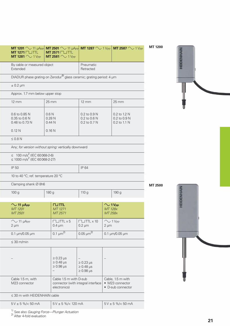
21
MT 1201 » 11 µAPPMT 1271 « TTLMT 1281 » 1 VPP
MT 2501 » 11 µAPPMT 2571 « TTLMT 2581 » 1 VPP
MT 1287 » 1 VPP MT 2587 » 1 VPP
By cable or measured object Extended
PneumaticRetracted
DIADUR phase grating on Zerodur® glass ceramic; grating period: 4 µm
± 0.2 µm
Approx. 1.7 mm below upper stop
12 mm 25 mm 12 mm 25 mm
0.6 to 0.85 N0.35 to 0.6 N0.48 to 0.73 N
0.12 N
0.6 N0.28 N0.44 N
0.16 N
0.2 to 0.9 N0.2 to 0.6 N0.2 to 0.7 N
0.2 to 1.2 N0.2 to 0.9 N0.2 to 1.1 N
† 0.8 N
Any; for version without spring: vertically downward
† 100 m/s2 (IEC 60068-2-6)† 1000 m/s2 (IEC 60068-2-27)
IP 50 IP 64
10 to 40 °C; ref. temperature 20 °C
Clamping shank ¬ 8h6
100 g 180 g 110 g 190 g
» 11 µAPP
MT 1201MT 2501
« TTL
MT 1271MT 2571
» 1 VPP
MT 128xMT 258x
» 11 µAPP2 µm
« TTL x 50.4 µm
« TTL x 100.2 µm
» 1 VPP2 µm
0.1 µm/0.05 µm 0.1 µm2) 0.05 µm2) 0.1 µm/0.05 µm
† 30 m/min
– ‡ 0.23 µs‡ 0.48 µs‡ 0.98 µs–
–‡ 0.23 µs‡ 0.48 µs‡ 0.98 µs
–
Cable 1.5 m, withM23 connector
Cable 1.5 m with D-sub connector (with integral interface electronics)
Cable, 1.5 m withM23 connectorD-sub connector
••
† 30 m with HEIDENHAIN cable
5 V ± 5 %/< 50 mA 5 V ± 5 %/< 120 mA 5 V ± 5 %/< 50 mA
1) See also Gauging Force—Plunger Actuation2) After 4-fold evaluation
MT 1200
MT 2500

���������� ������� ����������������������������
22
HEIDENHAIN-METRO
Length Gauges with ± 0.5 µm/± 1 µm AccuracyLarge measuring ranges
For dimensional and positional measurement
•
•
Large measuring ranges together with their high accuracy make the MT 60 and MT 101 HEIDENHAIN-METRO length gauges attractive for incoming inspection, production monitoring, quality control, or anywhere parts with very different dimensions are measured. But they are also easy to mount as highly accurate position encoders, for example on sliding devices or X-Y tables.
Plunger actuation
M version length gauges feature an integral motor that retracts and extends the plunger. While the MT 101M operates at a constant gauging force, the MT 60M allows you to select from three gauging force levels. K version gauges have no integral plunger actuation. The plunger is freely movable. It can be connected to moving elements such as linear slides and X-Y table by a coupling (see Accessories).
Mounting
The length gauges are mounted onto afl at surface by two screws. The M versions can also be mounted in the MS 100 and MS 200 gauge stands.
Output signals
The MT 60 and MT 101 provide » 11 µAPP current signals for HEIDENHAIN subsequent electronics.
r = Reference mark position
mm
MT 60
MT 101

23
MT 60M
MT 101M
Specifi cations MT 60M
MT 60K
MT 101M
MT 101K
Plunger MT xxMactuation MT xxK
MotorizedPlunger connected via separate coupling with moving machine part
Measuring standard DIADUR grating on silica glass; grating period 10 µm
System accuracy ± 0.5 µm ± 1 µm
Recommd. meas. step 1 µm to 0.1 µm
Reference mark Approx. 1.7 mm from top Approx. 10 mm from top
Measuring range 60 mm 100 mm
Gauging force
Vertically downwardVertically upwardHorizontal
With MT 60M1 N/1.25 N/1.75 N– /– /0.75 N– /0.75 N/1.25 N
With MT 101M0.7 N with SG 101V–0.7 N with SG 101H
Required moving force
for MT xxK0.1 to 0.6 N (depending on the operating attitude)
0.5 to 2 N (depending onthe operating attitude)
Permissible radial force † 0.5 N † 2 N
Operating MT xxMattitude
MT xxK
Any
Any
Vertically downward withSG 101VHorizontal with SG 101HAny
Vibration 55 to 2000 HzShock 11 ms
† 100 m/s2 (IEC 60068-2-6)† 1000 m/s2 (IEC 60068-2-27)
Protection IEC 60529 IP 50
Operating temperature 10 to 40 °C; ref. temperature 20 °C
Fastening Plane surface
Weight MT xxMwithout cable MT xxK
700 g600 g
1400 g1200 g
Incremental signals » 11 µAPP; signal period 10 µm
Measuring velocity1) † 18 m/min † 60 m/min
Electrical connection
Cable lengthCable 1.5 m with M23 connector (male) 9-pin;† 30 m with HEIDENHAIN cable
Power MT xxMsupply MT xxK Switch box
5 V ± 5%/< 180 mA5 V ± 5%/< 120 mA–
5 V ± 5%/< 180 mA5 V ± 5%/< 120 mAVia power adapter
Required accessories For MT 60M For MT 101M
Switch box SG 60M Vertical position: SG 101VHorizontal position: SG 101H
Power For 230 Vadapter For 110 V
––
ID 290262-01ID 231019-01
1) Depending on the subsequent electronics

�������
!"���
���#���
!���
�����
�
�
���
�$��
����
��������
����
���
�
%���
&
�
���
�
�����
��
���
�
���
�
&
��������
�
����
�
����
���
�
!���
�����
�
��������
!"���
���#���
���
��
��
� ����
��
����
� ����
����
����
��
��
�
��'
��
��
� ����
��
����
� ���
%���
&
���������� ������� ����������������������������
24
HEIDENHAIN-SPECTO
Length Gauges with ± 1 µm AccuracyVery compact dimensions
Splash-proof
•
•
Thanks to their very small dimensions, the HEIDENHAIN-SPECTO length gauges are the product of choice for multipoint inspection apparatus and testing equipment.
Plunger actuation
The length gauges of the ST 12x8 and ST 30x8 series feature a spring-tensioned plunger that is extended at rest.
In the pneumatic length gauges ST 12x7 and ST 30x7 the plunger is retracted to its rest position by the integral spring. It is extended to the measuring position by the application of compressed air.
Mounting
The HEIDENHAIN-SPECTO length gauges are fastened by their 8h6 standard clamping shank.
Output signals
The HEIDENHAIN-SPECTO length gauges are available with three different output signals.
The ST 120x and ST 300x versions supply sinusoidal current signals with 11 µAPP levels for HEIDENHAIN subsequent electronics.
The ST 128x and ST 308x length gauges provide sinusoidal voltage signals with 1 VPP levels, which permit high interpolation.
The ST 127x and ST 307x feature integrated digitizing and interpolation electronics with 5-fold or 10-fold interpolation (as ordered) and square-wave signals in TTL levels.
Mechanical Data
Plunger actuation
Position of plunger at rest
Measuring standard
System accuracy
Reference mark
Measuring range
Gauging force with retracting plunger1)
Vertically downwardVertically upwardHorizontal
Permissible radial force
Operating attitude
Vibration 55 to 2000 HzShock 11 ms
Protection IEC 60529
Operating temperature
Fastening
Weight without cable
Electrical Data
For length Gauges
Incremental signals*
Signal period
Recommended measuring step
Mech. permissible traversing speed
Edge separation a at
scanning frequency*/traverse speed
100 kHz † 72 m/min3)
50 kHz † 60 m/min 25 kHz † 30 m/min
Electrical connection*
Cable outlet*
Cable length
Power supply
* Please indicate when ordering1) See also Gauging Force—Plunger Actuation
ST 12x7
ST 30x7
r = Reference mark positions = Beginning of measuring length
mm

25
ST 1200
ST 3000
ST 1208 » 11 µAPPST 1278 « TTLST 1288 » 1 VPP
ST 3008 » 11 µAPPST 3078 « TTLST 3088 » 1 VPP
ST 1207 » 11 µAPPST 1277 « TTLST 1287 » 1 VPP
ST 3007 » 11 µAPPST 3077 « TTLST 3087 » 1 VPP
By measured objectExtended
PneumaticRetracted
DIADUR grating on glass; grating period 20 µm
± 1 µm
Approx. 5 mm below upper stop
12 mm 30 mm 12 mm 30 mm
0.6 to 2.4 N0.4 to 2.2 N0.5 to 2.3 N
0.6 to 1.4 N0.4 to 1.2 N0.5 to 1.3 N
0.4 to 3.0 Ndepending on pressure and position
0.4 to 3.0 Ndepending on pressure and position
† 0.8 N
Any
† 100 m/s2 (IEC 60068-2-6)† 1000 m/s2 (IEC 60068-2-27)
IP 64 (for connecting elements see Connecting Elements and Cables)
10 to 40 °C; ref. temperature 20 °C
Clamping shank ¬ 8h6
40 g 50 g 40 g 50 g
» 11 µAPP
ST 120xST 300x
« TTL
ST 127xST 307x
» 1 VPP
ST 128xST 308x
» 11 µAPP20 µm
« TTL x 54 µm
« TTL x 102 µm
» 1 VPP20 µm
1 µm/0.5 µm 1 µm2) 0.5 µm2) 1 µm/0.5 µm
† 72 m/min
– ‡ 0.48 µs‡ 0.98 µs‡ 1.98 µs
‡ 0.23 µs‡ 0.48 µs‡ 0.98 µs
–
Cable 1.5 m with M23 connector
Cable 1.5 m with D-sub connector (with integral interface electronics)
Cable, 1.5 m withM23 connectorD-sub connector
••
Axial or radial
† 30 m with HEIDENHAIN cable
5 V ± 10 %/< 35 mA 5 V ± 10 %/< 90 mA 5 V ± 10 %/< 40 mA
2) After 4-fold evaluation3) Mechanically limited

���������� ������� ����������������������������
26
Accessories
Measuring Contacts
Ball-type contact
Steel ID 202504-01Carbide ID 202504-02Ruby ID 202504-03
Domed contact
Carbide ID 229232-01
Flat contact
Steel ID 270922-01Carbide ID 202506-01
Pin-type contact
Steel ID 202505-01
Knife-edge contact
Steel ID 202503-01
Roller contact, steelFor a low-friction contact with moving surfaces
Crowned ID 202502-03Cylindrical ID 202502-04
Adjustable contact, carbideFor exact parallel alignment to the measuring plate surface
Flat ID 202507-01Knife-edged ID 202508-01
mm

���������� ������� ����������������������������
27
Switch Boxes, Coupling
Switch boxes for CT 2501, CT 6001,
MT 60M, MT 101M
Switch boxes are required for length gauges with motorized plunger actuation. The plunger is controlled through two push buttons or by external signal. The gauging force is adjustable at the SG 25M and SG 60M switch boxes in three stages.
SG 25M
ID 317436-01
SG 60M
ID 317436-02
SG 101V
For the MT 101M in vertical operationID 361140-01
SG 101H
For the MT 101M in horizontal operationID 361140-02
Connector (female) 3-pin
For external operation of the switch boxID 340646-05
Power adapter for SG 101V/H
A power adapter connected to the switch box powers the MT 101M.
Power adapter 230 VID 290262-01
Power adapter 110 VID 231019-01
Coupling
For connecting the plunger of the length gauge (MT 60K and MT 101K) to a moving machine element
ID 206310-01
mm
220 V version

���������� ������� ����������������������������
28
Accessories for HEIDENHAIN-CERTOGauge Stand
Holder for CS 200
For the CT 2501 with¬ 16 mm clamping shank
ID 324391-01
mm
No chips or fl aws
CS 200 Gauge Stand
For length gauges CT 2501* CT 6001
ID 221310-01
Total height 349 mmMeasuring plate ¬ 250 mmColumn ¬ 58 mmWeight 15 kg
*) with special holder

���������� ������� ����������������������������
29
Ceramic Suction Plate, Diaphragm Compressor
Ceramic suction plate
Wear-resistant working surface with high surface quality specifi cally for inspecting gauge blocks
ID 223100-01
The gauge block (class 1 or 2)—or any other object with a plane surface—is drawn by suction onto the top of the ceramic plate. The ceramic plate is likewise drawn to the granite base and held in place through negative gauge pressure.
Diaphragm compressor
Source of suction for drawing the measured object and ceramic suction plate
ID 227967-01
Line voltage 230 V/50 HzPower consumption 20 WWeight 2.3 kg
Set of parts
Parts for connecting the ceramic suction plate with the diaphragm compressor.
ID 233501-ZY
Compressed air tube, 3 mT-jointConnecting piece
mm
���������� ������� ����������������������������
���
���
���
��
30
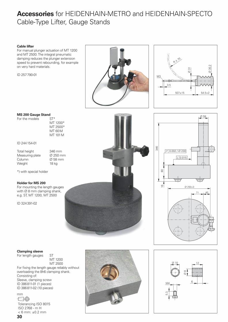
Accessories for HEIDENHAIN-METRO and HEIDENHAIN-SPECTOCable-Type Lifter, Gauge Stands
Cable lifter
For manual plunger actuation of MT 1200 and MT 2500. The integral pneumatic damping reduces the plunger extension speed to prevent rebounding, for example on very hard materials.
ID 257790-01
MS 200 Gauge Stand
For the models ST* MT 1200* MT 2500* MT 60M MT 101M
ID 244154-01
Total height 346 mmMeasuring plate ¬ 250 mmColumn ¬ 58 mmWeight 18 kg
*) with special holder
Holder for MS 200
For mounting the length gaugeswith ¬ 8 mm clamping shank,e.g. ST, MT 1200, MT 2500
ID 324391-02
Clamping sleeve
For length gauges ST MT 1200 MT 2500For fi xing the length gauge reliably without overloading the 8h6 clamping shank.Consisting of:Sleeve, clamping screwID 386811-01 (1 pieces)ID 386811-02 (10 pieces)
mm

���������� ������� ����������������������������
31
MS 45 Gauge Stand
For length gauges ST MT 1200 MT 2500
ID 202162-02
Total height 196.5 mmMeasuring plate ¬ 49 mmColumn ¬ 22 mmWeight 2.2 kg
MS 100 Gauge Stand
For length gauges ST MT 1200 MT 2500 MT 60M* MT 101M*
ID 202164-02
Total height 385 mmMeasuring plate 100 mm x 115 mmColumn ¬ 50 mmWeight 18 kg
*) with special holder
Holder for MS 100
For mounting the MT 60MID 207479-01
For mounting the MT 101MID 206260-01
mm

���������� ������� ����������������������������
��� ��� ����� ����� !"�#�$�� ��� �%�� ��& '���
! �(���� ��
��'��$
�����������
��
� ��
���
��
���
32
The ND 200B series offers display units for length gauges with sinusoidal output signals at 11 µAPP levels. The ND 281B can also support length gauges with sinusoidal 1 VPP signals.
Features
The ND 281B and ND 282B provide functions for sorting and tolerance
checking or for minimum/maximum
fi nding from a series of measurements. The ND 231B with sum/difference
display can display the output from two length gauges. With their switching
inputs and outputs, these length gauges are also ideal for simple automation tasks.
Data interfaces
To transmit the results of measurementsat inspection stations through a data interface to a printer or to a PC for further processing, the length gauges feature a serial RS-232-C/V.24 data interface or a parallel BCD output.
RS-232-C/V.24
The ND 221B, ND 231B and ND 281B are equipped with the serial RS-232-C interface according to EIA standards, also known as the V.24 interface according to CCITT recommendation. The data transfer rate is adjustable from 110 to 38400 baud.
Accessories:Data transfer cable RS-232-C
Wired with a 25-pin D-sub male connector and a 9-pin D-sub female connectorID 368017-xx
BCD
The ND 282B transmits the measured value parallel in binary-coded decimal code (BCD) in TTL levels.
The data output can be started at the ND keyboard, through an external command, through the RS-232-C/V.24 software command Ctrl B, or with BCD over an adjustable internal clock. This places the measured value in a buffer memory and then transmits it.
Measured Value Display Units
ND 200B Series
mm
Encoder inputs
Input frequency
Subdivision factor
Display step1)
Display
Status display
Features
Axis error
compensation
Data interface
Transfer rates
Switching outputs
For tasks in automation
Switching inputs
For tasks in automation
Power supply unit
Power consumption
Operating
temperature
Protection IEC 60529
Weight

33
ND 221B ND 281B ND 282B ND 231B
1 x » 11 µAPP 1 x » 11 µAPP or1 x » 1 VPPselectable
1 x » 11 µAPP 2 x » 11 µAPP
† 100 kHz 11 µAPP: † 100 kHz1 VPP: † 500 kHz
† 50 kHz † 100 kHz
Up to 1024-fold Up to 200-fold Up to 1024-fold
0.002 µm to 5 µm 0.1 µm to 5 µm 0.002 µm to 5 µm
Position values in 9 decades plus sign; REF, inch, datum 1/datum 2, SET datum setting
Scaling factor (SCL)
PRINT, MIN/MAX/DIFF/ACTL, START, sorting (< = >),scaling factor (SCL)
REF reference mark evaluation for distance-coded or single reference marksTwo reference points; fast zero reset
••
– Sorting and tolerance check modeMinimum/maximum value storage
••
Sorting and tolerance check modeSum/difference display
•
•
Linear and nonlinear over 64 points
RS-232-C/V.24 BCD RS-232-C/V.24
110 to 38400 baud 0.2 µs to 25.6 µs2) 110 to 38400 baud
– Zero crossoverSwitching points 1 and 2Sorting signals “<” and “>”Error
••••
– Zero reset, presetMeasured value output, display freeze if necessary (pulse or contact)Pass over reference pointInhibit reference pulse X1
••••
External MIN/MAX selectionMIN displayMAX displayDIFF displayStart measurement series
•••••
X1 or X2 displaySum displayDifference displayInhibit reference pulse X2
••••
– Deactivate BCD –
Primary-clocked power supply 100 Vac to 240 Vac (–15% to +10%) 50 Hz to 60 Hz (±2 Hz)
8 W
0 °C to 45 °C
IP 40, front panel IP 54
1.5 kg
1) Depends on the signal period of the connected length gauge2) Latch rate with fast concurrent BCD output

����
���
���
����
�
�� �
34
Features of the Display Units
The display units feature user-oriented functions that, together with a length gauge, form a stand-alone measuring station.
REF reference mark evaluation
When the power is turned off or unintentionally interrupted, the assignment of display values to plunger positions as last established by a zero reset or datum setting becomes lost. With the aid of the reference mark evaluation feature (REF), the assignment can be recovered simply by crossing over the reference mark.
Reference points
The ND 200 series display units allow you to set two datum points. A simple touch of a key switches from one datum point to the other.
Changing the counting direction
You can assign the positive counting direction to plunger retraction or extension as desired.
Changing the display step
The display step can be easily switched to adjust to the respective application.
Switching outputs
Switching outputs are available for semi-automatic positioning tasks. These can be used, for example, for deceleration and limit stop activation.
Maximum/minimum value storage
The ND 281B and ND 282B displays can store the maximum and minimum value from a series of measurements. A measure-ment series is started either on the keypad or by a switching input at the D-sub connection.
At the beginning of a measuring series the display unit saves the fi rst measured value in its minimum/maximum value memory. Every 0.5 ms the display then compares the current measured value with the values in memory; it stores a new value if the measurement is greater than the stored maximum or less than the stored minimum value.
The minimum, the maximum, the difference between the two values, or the current measured value can be called either via the keypad or through a switching input of the D-sub connection.
Sorting and tolerance check mode
The ND 231B, ND 281B and ND 282B displays can check parts for dimensional accuracy and sort them into classes. To sort the parts, the display unit compares the displayed measured value with an upper and lower limit value previously entered with the keypad. The result of the evaluation (whether the measured value is below, above or within tolerance) is indicated in the status display with one of the symbols <, = or >. In addition, a corresponding signal is available at the switching outputs (D-sub).
Sum/difference display
The ND 231B has two length gauge inputs. The ND 231B calculates the sum or difference of the two measured values and displays the result. The measured values from the two length gauges can also be displayed individually.

35
IK 220
Universal PC counter card
The IK 220 is an expansion board for AT-compatible PCs for recording the measured values of two incremental or absolute
linear or angle encoders. The subdivision and counting electronics subdivide the sinusoidal input signals up to 4096-fold. A driver software package is included in delivery.
For more information, see the IK 220 Product Information sheet.
IK 220
Input signals
(switchable)» 1 VPP » 11 µAPP EnDat 2.1 SSI
Encoder inputs Two D-sub connectors (15-pin), male
Input frequency † 500 kHz † 33 kHz –
Cable length † 60 m † 10 m
Signal subdivision
(signal period: meas. step) Up to 4096-fold
Data register for measured
values (per channel)48 bits (44 bits used)
Internal memory For 8192 position values
Interface PCI bus (plug and play)
Driver software and
demonstration program
For WINDOWS 98/NT/2000/XP
In VISUAL C++, VISUAL BASIC and BORLAND DELPHI
Dimensions Approx. 190 mm × 100 mm
Counter Cards

36
Interfaces
Incremental Signals » 1 VPP
HEIDENHAIN encoders with » 1 VPP interface provide voltage signals that can be highly interpolated.
The sinusoidal incremental signals A and B are phase-shifted by 90° elec. and have an amplitude of typically 1 VPP . The illustrated sequence of output signals—with B lagging A—applies for the direction of motion shown in the dimension drawing.
The reference mark signal R has a usable component G of approx. 0.5 V. Next to the reference mark, the output signal can be reduced by up to 1.7 V to a quiescent value H. This must not cause the subsequent electronics to overdrive. Even at the lowered signal level, signal peaks with the amplitude G can also appear.
The data on signal amplitude apply when the power supply given in the specifi cations is connected to the encoder. They refer to a differential measurement at the 120 ohm terminating resistor between the associated outputs. The signal amplitude decreases with increasing frequency. The cutoff
frequency indicates the scanning frequency at which a certain percentage of the original signal amplitude is maintained:
–3 dB cutoff frequency:70 % of the signal amplitude–6 dB cutoff frequency:50 % of the signal amplitude
Interpolation/resolution/measuring step
The output signals of the 1 VPP interface are usually interpolated in the subsequent electronics in order to attain suffi ciently high resolutions. For velocity control, interpolation factors are commonly over 1000 in order to receive usable velocity information even at low speeds.
Measuring steps for position measurement are recommended in the specifi cations. For special applications, other resolutions are also possible.
Short-circuit stability
A temporary short circuit of one output to 0 V or UP does not cause encoder failure, but it is not a permissible operating condition.
Short circuit at 20 °C 125 °C
One output < 3 min < 1 min
All outputs < 20 s < 5 s
•
•
Interface Sinusoidal voltage signals » 1 VPP
Incremental signals 2 nearly sinusoidal signals A and B
Signal amplitude M: 0.6 to 1.2 VPP; typically 1 VPPAsymmetry |P – N|/2M: † 0.065Amplitude ratio MA/MB: 0.8 to 1.25Phase angle Iϕ1 + ϕ2I/2: 90° ± 10° elec.
Reference mark
signal
1 or more signal peaks R
Usable component G: 0.2 to 0.85 VQuiescent value H: 0.04 V to 1.7 VSwitching threshold E, F: ‡ 40 mVZero crossovers K, L: 180° ± 90° elec.
Connecting cable
Cable lengthPropagation time
HEIDENHAIN cable with shieldingPUR [4(2 x 0.14 mm2) + (4 x 0.5 mm2)]Max. 150 m distributed capacitance 90 pF/m6 ns/m
Any limited tolerances in the encoders are listed in the specifi cations.
Signal period360° elec.
Rated value
A, B, R measured with oscilloscope in differential mode
Cutoff frequency
Typical signal amplitude curve with respect to the scanning frequency
Sig
nal a
mp
litu
de [%
] �
Scanning frequency [kHz] �–3dB cutoff frequency–6dB cutoff frequency

37
Input circuitry of the subsequent
electronics
Dimensioning
Operational amplifi er MC 34074Z0 = 120 −R1 = 10 k− and C1 = 100 pFR2 = 34.8 k− and C2 = 10 pFUB = ±15 VU1 approx. U0
–3dB cutoff frequency of circuitry
Approx. 450 kHzApprox. 50 kHz with C1 = 1000 pF and C2 = 82 pFThe circuit variant for 50 kHz does reduce the bandwidth of the circuit, but in doing so it improves its noise immunity.
Circuit output signals
Ua = 3.48 VPP typicalGain 3.48
Signal monitoring
A threshold sensitivity of 250 mVPP isto be provided for monitoring the 1 VPP incremental signals.
Incremental signals
Reference mark
signal
Ra < 100 −,typically 24 −Ca < 50 pFΣIa < 1 mAU0 = 2.5 V ± 0.5 V(relative to 0 V of the power supply)
Pin Layout
12-pin coupling M23 12-pin connector M23 15-pin D-sub connector
for IK 115/IK 215 or on encoder
Power supply Incremental signals Other signals
12 2 10 11 5 6 8 1 3 4 9 7 /
4 12 2 10 1 9 3 11 14 7 5/8/13/15 14 /
UP Sensor
UP
0 V Sensor
0 VA+ A– B+ B– R+ R– Vacant Vacant Vacant
Brown/Green
Blue White/Green
White Brown Green Gray Pink Red Black / Violet Yellow
Shield on housing; UP = power supply voltageSensor: The sensor line is connected internally with the corresponding power line / Color assignment applies only to extension cable
Encoder Subsequent electronics

���
)�
��� ��� ��� �� ��� ��� ���
��
��
��
���
�
����
38
Interfaces
Incremental signals « TTL
HEIDENHAIN encoders with « TTL interface incorporate electronics that digitize sinusoidal scanning signals withor without interpolation.
The incremental signals are transmitted as the square-wave pulse trains Ua1 and Ua2, phase-shifted by 90° elec. The reference
mark signal consists of one or more reference pulses Ua0, which are gated with the incremental signals. In addition, the integrated electronics produce their inverse
signals �, £ and ¤ for noise-proof transmission. The illustrated sequence of output signals—with Ua2 lagging Ua1—applies for the direction of motion shown in the dimension drawing.
The fault-detection signal ¥ indicates fault conditions such as breakage of the power line or failure of the light source. It can be used for such purposes as machine shut-off during automated production.
The distance between two successive edges of the incremental signals Ua1 and Ua2 through 1-fold, 2-fold or 4-fold evaluation is one measuring step.
The subsequent electronics must be designed to detect each edge of the square-wave pulse. The minimum edge
separation a listed in the Specifi cations applies for the illustrated input circuitry with a cable length of 1 m, and refers toa measurement at the output of the differential line receiver. Propagation-time differences in cables additionally reduce the edge separation by 0.2 ns per meterof cable length. To prevent counting error, design the subsequent electronics to process even as little as 90% of the resulting edge separation. The max. permissible shaft speed or traversing
velocity must never be exceeded.
The permissible cable length for transmission of the TTL square-wave signals to the subsequent electronics depends on the edge separation a. It is max. 100 m, or 50 m for the fault detection signal. This requires, however, that the power supply (see Specifi cations) be ensured at the encoder. The sensor lines can be used to measure the voltage at the encoder and, if required, correct it with an automatic system (remote sense power supply).
Interface Square-wave signals « TTL
Incremental signals 2 TTL square-wave signals Ua1, Ua2 and their inverted signals �, £
Reference mark
signal
Pulse widthDelay time
1 or more square-wave pulses Ua0 and their inverted pulses ¤90° elec. (other widths available on request); LS 323: ungated|td| † 50 ns
Fault detection
signal
Pulse width
1 TTL square-wave pulse ¥Improper function: LOW (upon request: Ua1/Ua2 at high impedance)Proper function: HIGHtS ‡ 20 ms
Signal level Differential line driver as per EIA standard RS-422UH ‡ 2.5 V at –IH = 20 mAUL † 0.5 V at IL = 20 mA
Permissible load Z0 ‡ 100 − between associated outputs|IL| † 20 mA max. load per outputCload † 1000 pF with respect to 0 VOutputs protected against short circuit to 0 V
Switching times
(10% to 90%)t+ / t– † 30 ns (typically 10 ns)with 1 m cable and recommended input circuitry
Connecting cable
Cable lengthPropagation time
HEIDENHAIN cable with shieldingPUR [4(2 × 0.14 mm2) + (4 × 0.5 mm2)]Max. 100 m (¥ max. 50 m) distributed capacitance 90 pF/m6 ns/m
Signal period 360° elec. Fault
Measuring step after
4-fold evaluation
Inverse signals �, £, ¤ are not shown
Permissible cable
length
with respect to the edge separation
Cab
le len
gth
[m
] �
Edge separation [µs] �
Without ¥
With ¥

39
Input circuitry of the subsequent
electronics
Dimensioning
IC1 = Recommended differential line receiver
DS 26 C 32 AT Only for a > 0.1 µs: AM 26 LS 32 MC 3486 SN 75 ALS 193
R1 = 4.7 k−R2 = 1.8 k−Z0 = 120 −C1 = 220 pF (serves to improve noise
immunity)
Incremental signals
Reference mark
signal
Fault detection
signal
Encoder Subsequent electronics
Pin Layout
15-pin D-sub
connector
at
encoder
12-pin
HEIDENHAIN
connector
Power supply Incremental signals Other signals
12 2 10 11 5 6 8 1 3 4 7 / 9
4 12 2 10 1 9 3 11 14 7 13 5/6/8 15
UP Sensor
UP
0 V Sensor
0 VUa1 � Ua2 £ Ua0 ¤ ¥1)
Vacant Vacant2)
Brown/Green
Blue White/Green
White Brown Green Gray Pink Red Black Violet – Yellow
Shield on housing; UP = Power supplySensor: The sensor line is connected internally with the corresponding power line 1) LS 323: Vacant 2) Exposed linear encoders: Switchover TTL/11 µAPP for PWT / Color assignment applies only to extension cable

�
���
��
�
40
Interfaces
Incremental Signals » 11 µAPP
HEIDENHAIN encoders with »11 µAPP interface provide current signals. They are intended for connection to ND measured value display units or EXE pulse-shaping electronics from HEIDENHAIN.
The sinusoidal incremental signals I1 and I2 are phase-shifted by 90° elec. and have signal levels of approx. 11 µAPP.The illustrated sequence of output signals—I2 lagging I1—applies for the retracting plunger.
The reference mark signal I0 has a usable component G of approx. 5.5 µA.
The data on signal amplitude apply when the power supply given in the Specifi cations is connected at the encoder. They refer toa differential measurement between the associated outputs. The signal amplitude decreases with increasing frequency. The cutoff frequency indicates the scanning frequency at which a certain percentage of the original signal amplitude is maintained:
–3 dB cutoff frequency:70 % of the signal amplitude–6 dB cutoff frequency:50 % of the signal amplitude
Interpolation/resolution/measuring step
The output signals of the 11 µAPP interface are usually interpolated in the subsequent electronics in order to attain suffi ciently high resolutions.
Measuring steps for position measure-
ment are recommended in the Specifi cations. For special applications, other resolutions are also possible.
•
•
Interface Sinusoidal current signals » 11 µAPP
Incremental signals 2 nearly sinusoidal signals I1 and I2Signal amplitude M: 7 to 16 µAPP/typically 11 µAPPAsymmetry IP – NI/2M: † 0.065Amplitude ratio MA/MB: 0.8 to 1.25Phase angle Iϕ1 + ϕ2I/2: 90° ± 10° elec.
Reference mark
signal
1 or more signal peaks I0Usable component G: 2 to 8.5 µASwitching threshold E, F: ‡ 0.4 µAZero crossovers K, L: 180° ± 90° elec.
Connecting cable
Cable lengthPropagation time
HEIDENHAIN cable with shieldingPUR [3(2 · 0.14 mm2) + (2 · 1 mm2)]Max. 30 m distributed capacitance 90 pF/m6 ns/m
Pin Layout
9-pin HEIDENHAIN connector
Power supply Incremental signals
3 4 Housing 9 1 2 5 6 7 8
UP 0 V External
shield
Inside
shield
I1 + I1 – I2 + I2 – I0 + I0 –
Brown White – White/Brown
Green Yellow Blue Red Gray Pink
UP = power supply voltageVacant pins or wires must not be used!
Shield on housingColor assignment applies only to extension cable.
Signal period360° elec.
Rated value
41
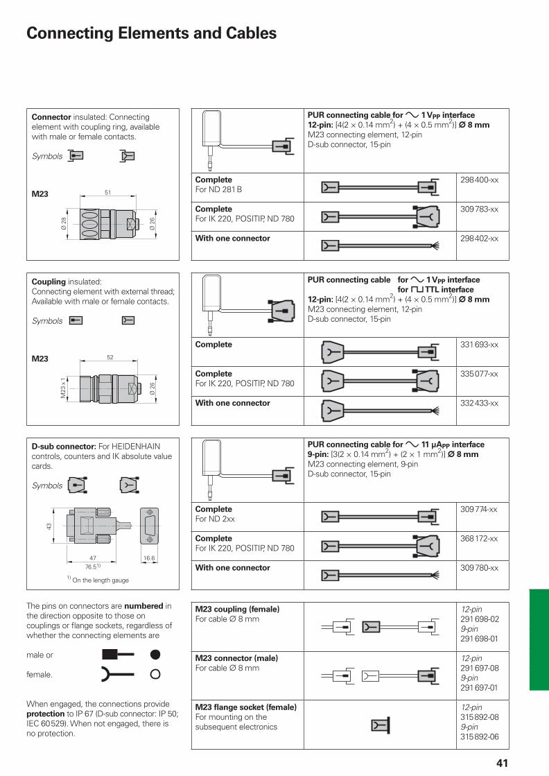
Connecting Elements and Cables
The pins on connectors are numbered in the direction opposite to those on couplings or fl ange sockets, regardless of whether the connecting elements are
male or
female.
When engaged, the connections provide protection to IP 67 (D-sub connector: IP 50; IEC 60529). When not engaged, there is no protection.
Connector insulated: Connecting element with coupling ring, available with male or female contacts.
Symbols
M23
M23
D-sub connector: For HEIDENHAIN controls, counters and IK absolute value cards.
Symbols
PUR connecting cable for » 1 VPP interface
12-pin: [4(2 × 0.14 mm2) + (4 × 0.5 mm2)] ¬ 8 mm
M23 connecting element, 12-pinD-sub connector, 15-pin
Complete
For ND 281B 298400-xx
Complete
For IK 220, POSITIP, ND 780 309783-xx
With one connector 298402-xx
PUR connecting cable for » 1 VPP interface
for « TTL interface
12-pin: [4(2 × 0.14 mm2) + (4 × 0.5 mm2)] ¬ 8 mm
M23 connecting element, 12-pinD-sub connector, 15-pin
Complete 331693-xx
Complete
For IK 220, POSITIP, ND 780 335077-xx
With one connector 332433-xx
PUR connecting cable for » 11 µAPP interface
9-pin: [3(2 × 0.14 mm2) + (2 × 1 mm2)] ¬ 8 mm
M23 connecting element, 9-pinD-sub connector, 15-pin
Complete
For ND 2xx 309774-xx
Complete
For IK 220, POSITIP, ND 780 368172-xx
With one connector 309780-xx
M23 coupling (female)
For cable ¬ 8 mm 12-pin
291698-029-pin291698-01
M23 connector (male)
For cable ¬ 8 mm 12-pin
291697-089-pin291697-01
M23 fl ange socket (female)
For mounting on the subsequent electronics
12-pin315892-089-pin315892-06
Coupling insulated: Connecting element with external thread;Available with male or female contacts.
Symbols
1) On the length gauge

42
*+���(
*+���
)����
�
General Electrical Information
Power supply
The encoders require a stabilized dc
voltage UP as power supply. The respective Specifi cations state the required power supply and the current consumption. The permissible ripple content of the dc voltage is:
High frequency interferenceUPP < 250 mV with dU/dt > 5 V/µsLow frequency fundamental rippleUPP < 100 mV
The values apply as measured at the encoder, i.e., without cable infl uences. The voltage can be monitored and adjusted with the device's sensor lines. If a controllable power supply is not available, the voltage drop can be halved by switching the sensor lines parallel to the corresponding power lines.
Calculation of the voltage drop:
¹U = 2 · 10–3 ·
where ¹U: Line drop in V LC: Cable length in m I: Current consumption in mA AP: Cross section of power lines in
mm2
•
•
LC · I56 · AP
Rigid confi guration
Frequent fl exing
Frequent fl exing
Cables Cross section of power supply lines AP Bend radius R
1 VPP/TTL/HTL 11 µAPP EnDat/SSI
17-pinEnDat
4)
8-pinRigid con-
fi guration
Frequent
fl exing
¬ 3.7 mm 0.05 mm2 – – – ‡ 8 mm ‡ 40 mm
¬ 4.5 mm
¬ 5.1 mm
0.14/0.052) mm2 0.05 mm2 0.05 mm2 0.14 mm2
‡ 10 mm ‡ 50 mm
¬ 6 mm
¬ 10 mm1)
0.19/0.143) mm2 – 0.08 mm2 0.34 mm2
‡ 20 mm‡ 35 mm
‡ 75 mm‡ 75 mm
¬ 8 mm
¬ 14 mm1)
0.5 mm2 1 mm2 0.5 mm2 1 mm2 ‡ 40 mm‡ 100 mm
‡ 50 mm‡ 100 mm
1)Metal armor 2)Length gauges 3)LIDA 400 4)Also Fanuc, Mitsubishi
Connect HEIDENHAIN position encoders only to subsequent electronics whose power supply is generated through double or strengthened insulation against line voltage circuits. Also see IEC 364-4-41: 1992, modifi ed Chapter 411 regarding “protection against both direct and indirect touch” (PELV or SELV). If position encoders or electronics are used in safety-related applications, they must be operated with protective extra-low voltage (PELV) and provided with overcurrent protection or, if required, with overvoltage protection.
Cables
It is absolutely necessary to use HEIDENHAIN cables for safety-related
applications. The cable lengths listed in the Specifi cations apply only for HEIDENHAIN cables and the recommended input circuitry of the subsequent electronics.
Durability
All encoders have polyurethane (PUR) cables. PUR cables are resistant to oil, hydrolysis and microbes in accordance with VDE 0472. They are free of PVC and silicone and comply with UL safety directives. The UL certifi cation AWM STYLE 20963 80 °C 30 V E63216 is documented on the cable.
Temperature range
HEIDENHAIN cables can be usedfor rigid confi guration –40 to +85 °Cfor frequent fl exing –10 to +85 °C
Cables with limited resistance to hydrolysis and microbes are rated for up to 100 °C. If required, please ask for assistance from HEIDENHAIN Traunreut.
Bend radius
The permissible bend radii R depend on the cable diameter and the confi guration:
••
Initial transient response of the supply voltage
and switch-on/switch-off behavior
Switch-on/off behavior of the encoders
The output signals are valid no sooner than after switch-on time tSOT = 1.3 s (see diagram). During time tSOT they can have any levels up to 5.5 V (with HTL encoders up to UPmax). If an interpolation electronics unit is inserted between the encoder and the power supply, the unit's switch-on/off characteristics must also be considered. When the power supply is switched off, or when the supply voltage falls below Umin, the output signals are also undefi ned. These data apply only for the encoders listed in the catalog—customized interfaces are not considered.
Encoders with new features and increased performance range may take longer to switch on (longer time tSOT). If you are responsible for developing subsequent electronics, please contact HEIDENHAIN in good time.
Isolation
The encoder housings are isolated against internal circuits.Rated surge voltage: 500 V(preferred value as per VDE 0110 Part 1, overvoltage category II, contamination level 2)
UPP
Output signals invalid InvalidValid

43
Minimum distance from sources of interference
Electrically permissible speed/
traversing speed
The maximum permissible shaft speed or traversing velocity of an encoder is derived from
the mechanically permissible shaft speed/traversing velocity (if listed in Specifi cations)andthe electrically permissible shaft speed or traversing velocity.For encoders with sinusoidal output
signals, the electrically permissible shaft speed or traversing velocity is limited by the –3dB/ –6dB cutoff frequency or the permissible input frequency of the subsequent electronics.For encoders with square-wave signals, the electrically permissible shaft speed/traversing velocity is limited by– the maximum permissible scanning
frequency fmax of the encoderand
– the minimum permissible edge separation a for the subsequent electronics.
For angular or rotary encoders
nmax = · 60 · 103
For linear encoders
vmax = fmax · SP · 60 · 10–3
where nmax: Electrically permissible speed in rpm vmax: Electrically permissible traversing
speed in m/min fmax: Max. scanning/output frequency of
encoder or input frequency of subsequent electronics in kHz
z: Line count of the angle or rotary encoder per 360°
SP: Signal period of the linear encoder in µm
•
•
fmaxz
Noise-free signal transmission
Electromagnetic compatibility/
CE compliance
When properly installed, and when HEIDENHAIN connecting cables and cable assemblies are used, HEIDENHAIN encoders fulfi ll the requirements for electromagnetic compatibility according to 89/336/EEC with respect to the generic standards for:
Noise immunity EN 61 000-6-2:
Specifi cally:– ESD EN 61 000-4-2– Electromagnetic fi elds EN 61 000-4-3– Burst EN 61 000-4-4– Surge EN 61 000-4-5– Conducted disturbances EN 61 000-4-6– Power frequency magnetic fi elds EN 61 000-4-8– Pulse magnetic fi elds EN 61 000-4-9
Interference EN 61 000-6-4:
Specifi cally:– For industrial, scientifi c and medical (ISM) equipment EN 55 011– For information technology equipment EN 55 022
Transmission of measuring signals—
electrical noise immunity
Noise voltages arise mainly through capacitive or inductive transfer. Electrical noise can be introduced into the system over signal lines and input or output terminals.Possible sources of noise are:
Strong magnetic fi elds from transformers, brakes and electric motorsRelays, contactors and solenoid valvesHigh-frequency equipment, pulse devices, and stray magnetic fi elds from switch-mode power suppliesAC power lines and supply lines to the above devices
•
•
•
••
•
Protection against electrical noise
The following measures must be taken to ensure disturbance-free operation:
Use only HEIDENHAIN cables.Use connectors or terminal boxes with metal housings. Do not conduct any extraneous signals.Connect the housings of the encoder, connector, terminal box and evaluation electronics through the shield of the cable. Connect the shielding in the area of the cable outlets to be as induction-free as possible (short, full-surface contact).Connect the entire shielding system with the protective ground.Prevent contact of loose connector housings with other metal surfaces.The cable shielding has the function of an equipotential bonding conductor. If compensating currents are to be expected within the entire system, a separate equipotential bonding conductor must be provided. Also see EN 50 178 / 4.98 Chapter 5.2.9.5 regarding “protective connection lines with small cross section.”Do not lay signal cables in the direct vicinity of interference sources (inductive consumers such as contacts, motors, frequency inverters, solenoids, etc.).Suffi cient decoupling from interference-signal-conducting cables can usually be achieved by an air clearance of 100 mm or, when cables are in metal ducts, by a grounded partition.A minimum spacing of 200 mm to inductors in switch-mode power supplies is required. Also see EN 50 178 / 4.98 Chapter 5.3.1.1 regarding cables and lines, EN 50 174-2 / 09.01 Chapter 6.7 regarding grounding and potential compensation.When using multiturn encoders in
electromagnetic fi elds greater than 30 mT, HEIDENHAIN recommends consulting with the main facility in Traunreut.
Both the cable shielding and the metal housings of encoders and subsequent electronics have a shielding function. The housings must have the same potential
and be connected to the main signal ground over the machine chassis or by means of a separate potential compensating line. Potential compensating lines should have a minimum cross section of 6 mm2 (Cu).
••
•
•
•
•
•
•
•
•

NL HEIDENHAIN NEDERLAND B.V. 6716 BM Ede, Netherlands { +31 (318) 581800 E-Mail: [email protected]
NO HEIDENHAIN Scandinavia AB 7300 Orkanger, Norway { +47 72480048 E-Mail: [email protected]
PH Machinebanks` Corporation Quezon City, Philippines 1113 { +63 (2) 7113751 E-Mail: [email protected]
PL APS 02-473 Warszawa, Poland { +48 228639737 E-Mail: [email protected]
PT FARRESA ELECTRÓNICA, LDA. 4470 - 177 Maia, Portugal { +351 229478140 E-Mail: [email protected]
RO Romania − HU
RU Gertner Service GmbH 113035 Moskau, Russian Federation { +7 (495) 931-9645 E-Mail: [email protected]
SE HEIDENHAIN Scandinavia AB 12739 Skärholmen, Sweden { +46 (8) 53193350 E-Mail: [email protected]
SG HEIDENHAIN PACIFIC PTE LTD. Singapore 408593, { +65 6749-3238 E-Mail: [email protected]
SK Slovakia − CZ
SL Posredništvo HEIDENHAIN SAŠO HÜBL s.p. 2000 Maribor, Slovenia { +386 (2) 4297216 E-Mail: [email protected]
TH HEIDENHAIN (THAILAND) LTD Bangkok 10250, Thailand { +66 (2) 398-4147-8 E-Mail: [email protected]
TR T&M Mühendislik Mümessillik 34728 Erenköy-Istanbul, Turkey { +90 (216) 3022345 E-Mail: [email protected]
TW HEIDENHAIN Co., Ltd. Taichung 407, Taiwan { +886 (4) 23588977 E-Mail: [email protected]
UA Ukraine − RU
US HEIDENHAIN CORPORATION Schaumburg, IL 60173-5337, USA { +1 (847) 490-1191 E-Mail: [email protected]
VE Maquinaria Diekmann S.A. Caracas, 1040-A, Venezuela { +58 (212) 6325410 E-Mail: [email protected]
VN AMS Advanced Manufacturing Solutions Pte Ltd HCM City, Viêt Nam { +84 (8) 9123658 - 8352490 E-Mail: [email protected]
ZA MAFEMA SALES SERVICES C.C. Midrand 1685, South Africa { +27 (11) 3144416 E-Mail: [email protected]
CS Serbia and Montenegro − BG
CZ HEIDENHAIN s.r.o. 106 00 Praha 10, Czech Republic { +420 272658131 E-Mail: [email protected]
DK TP TEKNIK A/S 2670 Greve, Denmark { +45 (70) 100966 E-Mail: [email protected]
ES FARRESA ELECTRONICA S.A. 08028 Barcelona, Spain { +34 934092491 E-Mail: [email protected]
FI HEIDENHAIN Scandinavia AB 02770 Espoo, Finland { +358 (9) 8676476 E-Mail: [email protected]
FR HEIDENHAIN FRANCE sarl 92310 Sèvres, France { +33 0141143000 E-Mail: [email protected]
GB HEIDENHAIN (G.B.) Limited Burgess Hill RH15 9RD, United Kingdom { +44 (1444) 247711 E-Mail: [email protected]
GR MB Milionis Vassilis 17341 Athens, Greece { +30 (210) 9336607 E-Mail: [email protected]
HK HEIDENHAIN LTD Kowloon, Hong Kong { +852 27591920 E-Mail: [email protected]
HR Croatia − SL
HU HEIDENHAIN Kereskedelmi Képviselet 1239 Budapest, Hungary { +36 (1) 4210952 E-Mail: [email protected]
ID PT Servitama Era Toolsindo Jakarta 13930, Indonesia { +62 (21) 46834111 E-Mail: [email protected]
IL NEUMO VARGUS MARKETING LTD. Tel Aviv 61570, Israel { +972 (3) 5373275 E-Mail: [email protected]
IN ASHOK & LAL Chennai – 600 030, India { +91 (44) 26151289 E-Mail: [email protected]
IT HEIDENHAIN ITALIANA S.r.l. 20128 Milano, Italy { +39 02270751 E-Mail: [email protected]
JP HEIDENHAIN K.K. Tokyo 102-0073, Japan { +81 (3) 3234-7781 E-Mail: [email protected]
KR HEIDENHAIN LTD. Suwon, South Korea, 443-810 { +82 (31) 2011511 E-Mail: [email protected]
MK Macedonia − BG
MX HEIDENHAIN CORPORATION MEXICO 20235 Aguascalientes, Ags., Mexico { +52 (449) 9130870 E-Mail: [email protected]
MY ISOSERVE Sdn. Bhd 56100 Kuala Lumpur, Malaysia { +60 (3) 91320685 E-Mail: [email protected]
AR NAKASE SRL. B1653AOX Villa Ballester, Argentina { +54 (11) 47684242 E-Mail: [email protected]
AT HEIDENHAIN Techn. Büro Österreich 83301 Traunreut, Germany { +49 (8669) 31-1337 E-Mail: [email protected]
AU FCR Motion Technology Pty. Ltd Laverton North 3026, Australia { +61 (3) 93626800 E-Mail: [email protected]
BE HEIDENHAIN NV/SA 1760 Roosdaal, Belgium { +32 (54) 343158 E-Mail: [email protected]
BG ESD Bulgaria Ltd. Sofi a 1172, Bulgaria { +359 (2) 9632949 E-Mail: [email protected]
BR DIADUR Indústria e Comércio Ltda. 04763-070 – São Paulo – SP, Brazil { +55 (11) 5696-6777 E-Mail: [email protected]
BY Belarus − RU
CA HEIDENHAIN CORPORATION Mississauga, Ontario L5T2N2, Canada { +1 (905) 670-8900 E-Mail: [email protected]
CH HEIDENHAIN (SCHWEIZ) AG 8603 Schwerzenbach, Switzerland { +41 (44) 8062727 E-Mail: [email protected]
CN DR. JOHANNES HEIDENHAIN (CHINA) Co., Ltd. Beijing 101312, China { +86 10-80420000 E-Mail: [email protected]
DE HEIDENHAIN Technisches Büro Nord 12681 Berlin, Deutschland { (030) 54705-240 E-Mail: [email protected]
HEIDENHAIN Technisches Büro Mitte 08468 Heinsdorfergrund, Deutschland { (03765) 69544 E-Mail: [email protected]
HEIDENHAIN Technisches Büro West 58093 Hagen, Deutschland { (02331) 9579-0 E-Mail: [email protected]
HEIDENHAIN Technisches Büro Südwest 70771 Leinfelden-Echterdingen, Deutschland { (0711) 993395-0 E-Mail: [email protected]
HEIDENHAIN Technisches Büro Südost 83301 Traunreut, Deutschland { (08669) 31-1345 E-Mail: [email protected]
Vollständige Adressen siehe www.heidenhain.deFor complete addresses see www.heidenhain.de
������������ ��� ��������������� ��������������������������������������� ���������������� ����������������� �!"��#�$����������
������ !���� ��!�
Zu
m A
bh
eft
en
hie
r fa
lzen
! /
Fo
ld h
ere
fo
r fi
lin
g!
208 945-26 · 15 · 2/2007 · F&W · Printed in Germany · Subject to change without notice