Embed Size (px)
Citation preview
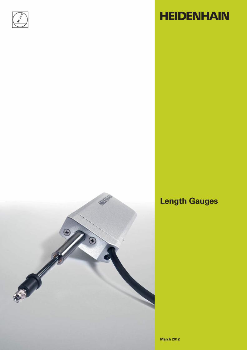
March 2012
Length Gauges

2
Length gauges from HEIDENHAIN offer high accuracy over long measuring ranges. These sturdily made gauges are available in application-oriented versions.
They have a wide range of applications in production metrology, in multipoint inspection stations, measuring equipment monitoring, and as position measuring devices.
This catalog supersedes all previous editions, which thereby become invalid.The basis for ordering from HEIDENHAIN is always the catalog edition valid when the contract is made.
Standards (ISO, EN, etc.) apply only where explicitly stated in the catalog.

Length Gauges – Applications and Products
Range of Applications, Application Examples 4
Length Gauges from HEIDENHAIN 6
Length Gauge Overview 8
Technical Features and Mounting Information
Principle of Function 10
Mechanical Design 11
Measuring Accuracy 12
Gauging Force and Plunger Actuation 14
Mounting 16
Specifi cations Accuracy Measuring range
ACANTO Absolute Length Gauges ± 2 µm 12 mm 18
HEIDENHAIN-CERTO
Incremental Length Gauges
± 0.1 µm; ± 0.03 µm*± 0.1 µm; ± 0.05 µm*
25 mm 60 mm
20
Incremental Length Gauges ± 0.2 µm 12 mm 25 mm
22
HEIDENHAIN-METRO
Incremental Length Gauges
± 0.5 µm± 1 µm
60 mm100 mm
24
HEIDENHAIN-SPECTO
Incremental Length Gauges
± 1 µm 12 mm 30 mm
26
Length Gauge Accessories
Measuring Contacts, Switch Boxes, Coupling 28
Gauge Stands, Ceramic Suction
Plate, Diaphragm Compressor
For HEIDENHAIN-CERTO 30
Cable-Type Lifter, Gauge Stands for HEIDENHAIN-METRO and HEIDENHAIN-SPECTO
32
Evaluation and Display Units
Digital Readouts 34
Evaluation Electronics 35
Electrical Connection
Interfaces Incremental Signals » 11 µAPP 37
Incremental Signals » 1 VPP 38
Incremental Signals « TTL 40
EnDat Absolute Position Values 42
Cables and Connecting Elements 44
General Electrical Information 48
* After linear length-error compensation in the evaluation electronics

4
Range of Applications
In Quality Assurance
Metrology and production
control
Incremental length gauges from HEIDENHAIN play a role in incoming goods inspection, fast dimension checking during production, statistical process control in production or quality assurance, or in any application where fast, reliable and accurate length measurement is required. Their large measuring lengths are a particular advantage: whether the part measures 5 mm or 95 mm, it is measured immediately with one and the same length gauge.
Whatever the application, HEIDENHAIN has the appropriate length gauge for the required accuracy. The HEIDENHAIN-
CERTO length gauges offer a very high accuracy of ± 0.1 µm/± 0.05 µm*/± 0.03 µm* for extremely precise measurement. Length gauges from the HEIDENHAIN-
METRO program have accuracy grades as fi ne as ± 0.2 µm, while the HEIDENHAIN-
SPECTO length gauges, with ± 1 µm accuracy, offer particularly compact dimensions.
* After linear length-error compensation in the evaluation electronics
Gauge block calibration and
measuring device inspection
The usual inspection of measuring equipment called for by standards, and the inspection of gauge blocks in particular, necessitate a large number of reference standard blocks if the comparative measurement is performed using inductive length gauges. The problem is the small measuring range of inductive gauges: they can measure length differences of only up to 10 µm. Incremental length gauges, which offer large measuring ranges together with high accuracy, greatly simplify the calibration of measuring devices required to ensure traceability.
The length gauges of the HEIDENHAIN-
CERTO program with measuring ranges of 25 mm with ± 0.1 µm/± 0.03 µm* accuracy and 60 mm with ± 0.1 µm/± 0.05 µm* accuracy are especially well suited for this task. It permits a signifi cant reduction in the required number of reference standard blocks, and recalibrating becomes much simpler.
Thickness gauging of silicon wafers
Inspection of styli
Calibration of gauge blocks

5
Multipoint inspection
apparatuses
Multipoint inspection devices require durable length gauges with small dimensions. They should also have relatively large measuring ranges of several millimeters with consistent linear accuracy in order to simplify the construction of inspection devices—for example by enabling the construction of one device for several masters. A large measuring length also provides benefi ts in master production, because simpler masters can be used.
Thanks to their small dimensions, the ACANTO absolute length gauge, like the HEIDENHAIN-SPECTO incremental length gauge, are specially designed for multi-point measuring stations. The feature accuracy grades up to ± 1 µm over measuring ranges up to 30 mm. Higher accuracy requirements up to ± 0.2 µm can be met with similarly compact HEIDENHAIN-METRO length gauges.
Unlike inductive gauges, HEIDENHAIN-SPECTO length gauges provide stable measurement over long periods—eliminating recalibration.
Position measurement
Incremental length gauges from HEIDENHAIN are also ideal for position measurement on precision linear slides or X-Y tables. Working with measuring microscopes, for example, becomes much easier thanks to the digital readout and the fl exible datum setting.
Here, length gauges from the HEIDENHAIN-METRO and HEIDENHAIN-
SPECTO program come into use with large measuring ranges of 30 mm, 60 mm or 100 mm at consistently high accuracy grades of ± 0.5 µm or ± 1 µm.
In this application as linear measuring device, the length gauge’s fast installation in accordance with the Abbe measuring principle by its clamping shank or planar mounting surface is of special benefi t.
Testing station for fl atness inspection
Position measurement on an X-Y table for lens mounting
In Production
Tolerance gauging of semifi nished products

6
Length Gauges from HEIDENHAIN
High accuracyThe high accuracy specifi ed for HEIDENHAIN length gauges applies over the entire measuring length. Whether the part measures 10 or 100 mm, its actual dimension is always measured with the same high quality. The high repeatability of HEIDENHAIN length gauges comes into play during comparative measurements, for example in series production.
A number of arguments speak for HEIDENHAIN length gauges. These include not only their technical features, but also their high quality standard and the worldwide presence of HEIDENHAIN.
Large measuring rangesHEIDENHAIN length gauges are available with measuring lengths of 12 mm, 25 mm, 30 mm, 60 mm or 100 mm. so that you can measure very different parts in one measuring setup and avoid frequently changing setups with expensive gauge blocks or masters.
Robust designHEIDENHAIN length gauges are built for an industrial environment. They feature consistently high accuracy over a long period of time as well as high thermal stability. They can therefore be used in production equipment and machines.

7
Wide range of applicationsHEIDENHAIN length gauges are suited for many applications. Automatic inspection equipment, manual measuring stations or positioning equipment—wherever lengths, spacing, thickness, height or linear motion are to be measured, HEIDENHAIN length gauges function quickly, reliably and accurately.
Know-howThe high quality of HEIDENHAIN length gauges is no coincidence. HEIDENHAIN has been manufacturing high-accuracy scales for over 70 years, and for many years it has developed measuring and testing devices for length and angle measurement for national standards laboratories. This know-how makes HEIDENHAIN an extraordinarily qualifi ed partner for metrology questions.
Worldwide presenceHEIDENHAIN is represented in all important industrial countries—in most of them with wholly owned subsidiaries. Sales engineers and service technicians support the user on-site with technical information and servicing in the local language.
Absolute position measurementThe ACANTO length gauges operate with absolute measurement over a range of 12 mm and with high repeatability. It's particular advantage is that the measured value is available immediately after switch-on.

CT 6000 CT 2500MT 101 MT 60
8
Length Gauge Overview
Accuracy Measuring range
Plunger actuation
Absolute position measurement
± 2 µm ACANTO
By measured object
Pneumatic
Incremental linear measurement
± 0.1 µm
± 0.05 µm*)
± 0.03 µm*)
HEIDENHAIN-CERTO
By motor
By external coupling
± 0.2 µm HEIDENHAIN-METRO
By cable lifter or measured object
Pneumatic
± 0.5 µm
± 1 µm
HEIDENHAIN-METRO
By motor
By external coupling
± 1 µm HEIDENHAIN-SPECTO
By measured object
Pneumatic
*) After linear length-error compensation in the evaluation electronics

ST 3000 ST 1200MT 2500 MT 1200 AT 1200AT
9
12 mm 25 mm/
30 mm
60 mm 100 mm Page
18
AT 1218 EnDat
AT 1217 EnDat
20
CT 2501 » 11 µAPP
CT 2502 » 11 µAPP
CT 6001 » 11 µAPP
CT 6002 » 11 µAPP
22
MT 1271 « TTLMT 1281 » 1 VPP
MT 1287 » 1 VPP
MT 2571 « TTLMT 2581 » 1 VPP
MT 2587 » 1 VPP
24
MT 60 M » 11 µAPP
MT 60 K » 11 µAPP
MT 101 M » 11 µAPP
MT 101 K » 11 µAPP
26
ST 1278 « TTLST 1288 » 1 VPP
ST 1277 « TTLST 1287 » 1 VPP
ST 3078 « TTLST 3088 » 1 VPP
ST 3077 « TTLST 3087 » 1 VPP

5 µm
10
Principle of Function
HEIDENHAIN length gauges are characterized by long measuring ranges and consistently high accuracy. The basis for both is the photoelectrical scanning principle.
HEIDENHAIN linear encoders use material measuring standards consisting of absolute or incremental graduations on substrates of glass or glass ceramic. These measuring standards permit large measuring ranges, are insensitive to vibration and shock, and have a defi ned thermal behavior. Changes in atmospheric pressure or relative humidity have no infl uence on the accuracy of the measuring standard—which is the prerequisite for the high long-term
stability of HEIDENHAIN length gauges.
The masters for these graduations are fabricated on dividing engines developed and built by HEIDENHAIN. High thermal stability during the manufacturing process ensures that the graduations have high
accuracy over the measuring length. The master graduation is applied to the carrier using the DIADUR copying process developed by HEIDENHAIN, which produces very thin but durable graduation structures of chromium.
The graduation is photoelectrically
scanned without mechanical contact and therefore without wear. Light passes through the structured scanning reticle and over the scale onto photovoltaic cells. The photovoltaic cells produce sinusoidal output signals with a small signal period. Interpolation in the subsequent electronics makes very small measuring steps into the nanometer range possible. The scanning principle, together with the extremely fi ne graduation lines and their high edge defi nition ensure the quality of the output signals as well as the small position error
within one signal period. This applies particularly to HEIDENHAIN length gauges, which use a DIADUR phase grating as measuring standard. The interferential scanning method produces sinusoidal incremental signals with a period of only 2 µm.
DIADUR phase grating with approx. 0.25 µm grating height
Grating period
Carrier
Reference mark
Incremental graduation
DIADUR graduation
Incremental Measuring Method
With the incremental measuring method, the graduation consists of a periodic grating structure. The position information is obtained by counting the individual increments (measuring steps) from some point of origin. Since an absolute reference is required to ascertain positions, the measuring standard is provided with an additional track that bears a reference
mark. The absolute position on the scale, established by the reference mark, is gated with exactly one signal period.The reference mark must therefore be scanned to establish an absolute reference or to fi nd the last selected datum.
Absolute measuring method
With the absolute measuring method, the position value is available from the encoder immediately upon switch-on and can be called at any time by the subsequent electronics. There is no need to move the axes to fi nd the reference position. The absolute position information is read from
the graduated disk, which is formed from a serial absolute code structure. A separate incremental track is interpolated for the position value and at the same time—depending on the interface version—is used to generate an optional incremental signal.

11
Mechanical Design
HEIDENHAIN length gauges function according to the Abbe measuring principle, i.e. the measuring standard and the plunger are exactly aligned. All components comprising the measuring loop, such as the measuring standard, plunger, holder and scanning head are designed in terms of their mechanical and thermal stability for the highest possible accuracy of the length gauge.
HEIDENHAIN length gauges have a defi ned thermal behavior. Since temperature variations during measurement can result in changes in the measuring loop, HEIDENHAIN uses special materials with low coeffi cients of expansion Þtherm for the components of the measuring loop, for example in the CERTO length gauges. The scale is manufactured of Zerodur (Þtherm 0 K–1), and the plunger and holder are of Invar (Þtherm 1 · 10–6 K–1). This makes it possible to guarantee its high measuring accuracy over a relatively large temperature range.
Length gauges from HEIDENHAIN feature a sturdy design. Even high vibration and shock loads have no negative infl uence on the accuracy.
The ball-bush guided plunger tolerates high radial forces and moves with very low friction. It has an M2.5 thread to hold measuring contacts.
Expendable parts
HEIDENHAIN length gauges contain components that are subject to wear, depending on the application and manipulation. These include in particular the following parts:
LED light source• Guideway (tested for at least 5 million • strokes*)Cable link for CT, MT 60 and MT 101 • (tested for at least 1 million strokes*)Scraper rings• Rubber bellows for AT and ST 1200•
* With CT, MT 60 M and MT 101 M only with actuation by switch box
Layout of ST 1200
Connecting cable
Measuring standard
Scanning unit with light source, photocells and scanning electronics
Ball-bush guide
Plunger
Rubber bellows
Measuring contact
Layout of CT 6000
MT 60
Measuring standard (scale)
Holder
Scanning unit with light source and photovoltaic cells
Ball-bush guide
Plunger
Measuring contact
DIADUR is a registered trademark of DR. JOHANNES HEIDENHAIN GmbH, Traunreut, Germany.Zerodur®is a registered trademark of Schott-Glaswerke, Mainz, Germany.

12
Measuring Accuracy
The accuracy of position measurement with length gauges is mainly determined by the following factors:
the quality of the graduation,• the quality of the scanning process,• the quality of the signal processing • electronics,the error from the scale guideway • relative to the scanning unit.
A distinction is made between position error over relatively large paths of traverse—for example the entire measuring range—and that within one signal period.
Position error over the measuring range
Length gauge accuracy is specifi ed as system accuracy, which is defi ned as follows:The extreme values of the total error
F—with reference to their mean value—lie over the entire measuring length within the system accuracy ± a. They are measured during the fi nal inspection and documented in the calibration chart.
Position error within one signal period
The position error u within one signal period is determined by the signal period of the length gauge, as well as the quality of the graduation and the scanning thereof. At any position over the entire measuring length, it does not exceed approx. ± 1 % of the signal period.
The smaller the signal period, the smaller the position error within one signal period.In the calibration chart of the HEIDENHAIN-CERTO, this position error within one signal period is shown as a tolerance band.
Signal period of the
scanning signals
Max. position error u within
one signal period (approx.)
CT 2500
CT 6000
2 µm ± 0.02 µm
MT 1200
MT 2500
2 µm ± 0.02 µm
MT 60
MT 101
10 µm ± 0.1 µm
ST 1200
ST 3000
20 µm ± 0.2 µm
AT 1200 188.4 µm ± 0.7 µm
Position error a over the measuring length ML
Po
sit
ion
err
or
Position error within
one signal period
Position
Position error u within one signal period
Signal period
360° elec.
Sig
nal le
vel
Po
sit
ion
err
or

13
All HEIDENHAIN length gauges are inspected before shipping for accuracy and proper function.
They are calibrated for accuracy during retraction and extension of the plunger. For the HEIDENHAIN-CERTO, the number of measuring positions is selected to ascertain very exactly not only the long-range error, but also the position error within one signal period.
The manufacturer’s inspection certifi cate
confi rms the specifi ed system accuracy of each length gauge. The calibration
standards ensure the traceability—as required by EN ISO 9001—to recognized national or international standards.
For the HEIDENHAIN-METRO and HEIDENHAIN CERTO series, a calibration
chart documents the position error over the measuring range. It also shows the measuring step and the measuring uncertainty of the calibration measurement.
For the HEIDENHAIN-METRO the calibration chart shows the mean value of one forward and one backward measuring stroke.
The HEIDENHAIN-CERTO is represented in the calibration chart as the envelope curve of the measured error. The HEIDENHAIN-CERTO length gauges are supplied with two calibration charts, each for different operating attitudes.
Example
Temperature range
The length gauges are inspected at a reference temperature of 20 °C. The system accuracy given in the calibration chart applies at this temperature.
The operating temperature indicates the ambient temperature limits between which the length gauges will function properly.The storage temperature range of –20 °C to 60 °C applies for the device in its packaging.
Operating attitude for calibration chart 2
Operating attitude for calibration chart 1

14
Gauging Force—Plunger Actuation
Gauging force
Gauging force is the force that the plunger exercises on the measured object. An excessively large gauging force can cause deformation of the measuring contact and the measured object. If the gauging force is too small, an existing dust fi lm or other obstacle may prevent the plunger from fully contacting the measured object. The gauging force depends on the type of plunger actuation.
Plunger actuation by spring
For the AT 1218, MT 12x1, MT 25x1, ST 12x8 and ST 30x8, the integral spring extends the plunger to the measuring position and applies the gauging force. In its resting position, the plunger is extended. The gauging force depends on the following criteria:
The operating attitude• The plunger position, because the gauging • force changes over the measuring rangeThe measuring direction, i.e., whether • the gauge measures with extending or retracting plunger
In the diagrams, the measuring force is shown over the measuring range for a retracting and extending plunger in a horizontal operating attitude.
Plunger actuation by measured object
The complete length gauge is moved relative to the measured object. The measurement is made with retracting plunger.
Plunger actuation via cable-type lifter
(MT 12x1, MT 25x1)
Through a cable mechanism, the plunger is retracted by hand and then extended onto the measured object. The measurement is made with extending plunger.
The diagrams apply for the horizontal
operating attitude. The following compensation values are to be taken into account for other operating attitudes.
Model Operating attitude vertically
Upward Downward
AT 121x – 0.12 N + 0.12 N
MT 12xx – 0.13 N + 0.13 N
MT 25x1 – 0.17 N + 0.17 N
MT 2587 – 0.19 N + 0.19 N
ST 12x7 – 0.07 N + 0.07 N
ST 12x8 – 0.08 N + 0.08 N
ST 30xx – 0.11 N + 0.11 N
Gau
gin
g fo
rce [
N]
Distance [mm]
MT 12x1 extendingMT 12x1 retractingST 12x8 extendingST 12x8 retractingAT 12x8 extendingAT 12x8 retracting
Gau
gin
g fo
rce [
N]
Distance [mm]
MT 25x1 extendingMT 25x1 retractingST 30x8 extendingST 30x8 retracting

15
Pneumatic plunger actuation
The pneumatically actuated plungers of the AT 1217, MT 1287, MT 2587, ST 12x7 and ST 30x7 length gauges are extended by the application of compressed air.When the air connection is ventilated, the integral spring retracts the plunger. to a protected resting position within the housing.
The gauging force can be adjusted to the measuring task through the level of air pressure. At constant pressure, it depends on the operating attitude and the plunger position.
The diagrams show the respective measuring force for a horizontal operating attitude depending on the compressed air applied with the plunger extending and retracting fully. These are approximate values that are subject to changes due to tolerances and depend on seal wear.
Motorized plunger actuation
The CT 2501, CT 6001, MT 60 M and MT 101 M length gauges feature an integral motor that moves the plunger. It is operated through the switch box either by push button or over the connection for external actuation. The plungers of the CT 2501, CT 6001, and MT 60 M length gauges must not be moved by hand if the switch box is connected.
The gauging force of the CT 2501, CT 6001, and MT 60 M motorized length gauges is adjustable in three stages through the switch box. The force remains constant over the measuring range but depends on the operating attitude.Regardless of the operating attitude—whether it measures vertically downward (with the SG 101 V switchbox) or horizontally (with the SG 101 H switch box)—the MT 101 M exercises a constant gauging force.
Switch box and power adapter (only with MT101 M) must be ordered separately.
External plunger actuation by coupling
For the CT 2502, CT 6002, MT 60 K, MT 101 K and special versions “without spring” of the MT 1200 and MT 2500, the plunger is freely movable. For position measurement, the plunger is connected by a coupling with a moving machine element. The force needed to move the plunger is specifi ed as the required moving force. It depends on the operating attitude.
Note
The compressed air introduced directly into the length gauges must be properly conditioned and must comply with the following quality classes as per ISO 8573-1 (1995 edition):
Solid contaminant: Class 1• (max. particle size 0.1 µm and max. particle density 0.1 mg/m3 at 1 · 105 Pa)Total oil content: Class 1• (max. oil concentration 0.01 mg/m3 at 1 · 105 Pa)Maximum pressure dew point: Class 4, • but with reference conditions of+3 °C at 2 · 105 Pa
HEIDENHAIN offers the DA 400
Compressed Air Unit for purifying compressed air.
For more information, ask for our DA 400 Product Information sheet.
Gau
gin
g fo
rce [
N]
Pressure [bars]
MT 12x7 retractedMT 12x7 extendedST 12x7 retractedST 12x7 extendedAT 12x7 retractedAT 12x7 extended
Gau
gin
g fo
rce [
N]
Pressure [bars]
MT 2587 retractedMT 2587 extendedST 30x7 retractedST 30x7 extended

16
Mounting
In addition to the length gauge itself, the mechanical design of the measuring setup also plays a role in defi ning the quality of measurement.
Abbe principle
HEIDENHAIN length gauges enable you to work according to the Abbe measuring principle: The measured object and scale must be in alignment to avoid additional measuring error.
Measuring loop
All components included in the measuring loop such as the holder for the measured object, the gauge stand with holder, and the length gauge itself infl uence the result of measurement. Expansion or deformation of the measuring setup through mechanical or thermal infl uences adds directly to the error.
Mechanical design
A stable measuring assembly must be ensured. Long lateral elements within the measuring loop are to be avoided. HEIDENHAIN offers a stable gauge stand as an accessory.
The force resulting from the measurement must not cause any measurable deformation of the measuring loop.Incremental length gauges from HEIDENHAIN operate with small gauging force and have very little infl uence on the measuring setup.
Thermal behavior
Temperature variations during measurement cause changes in length or deformation of the measuring setup. After a change in temperature of 5 K, a steel bar of 200 mm length expands by 10 µm.
Length changes resulting from a uniform deviation from the reference temperature can largely be compensated by resetting the datum on the measuring plate or a master; only the expansion of the scale and measured object go into the result of measurement. Temperature changes during measurement cannot be ascertained mathematically.
For critical components, HEIDENHAIN therefore uses special materials with low coeffi cients of expansion, such as are found in the HEIDENHAIN-CERTO gauge stand. This makes it possible to guarantee the high accuracy of HEIDENHAIN-CERTO even at ambient temperatures of 19 to 21 °C and variations of ± 0.1 K during measurement.
Thermally induced length change
Expansion of the measuring loop components as a result of heat
Acceleration
Shock and vibration of any kind is to be avoided during measurement so as not to impair the high accuracy of the length gauge.
The maximum values given in the specifi cations apply to the effect of external acceleration on the length gauge. They describe only the mechanical stability of the length gauge, and imply no guarantee of function or accuracy.
In the length gauge itself, unchecked extension of the spring-driven or non-coupled moving plunger can cause high acceleration onto the measured object or measuring plate surface. For the MT 1200 and MT 2500 series length gauges, use the cable-type lifter whenever possible (see Accessories). The cable lifter features adjustable pneumatic damping to limit the extension velocity to an uncritical value.
The measuring loop:
All components involved in the measuring assembly, including the length gauge

–
CT 6000
MT 60
MT 101
CT 2500
17
Fastening
The CT 6000, MT 60 and MT 101 length gauges are fastened by two screws onto a plane surface. This ensures a mechanically stable installation of even these large length gauges. Special holders are available for fastening the MT 60 and MT 101 to the MS 100 gauge stand for the HEIDENHAIN-METRO (see Accessories).
The CT 2500 is mounted by its standard clamping shank with 16h8 diameter. A holder is available for fastening the HEIDENHAIN-CERTO to the gauge stand (see Accessories).
The AT, ST, MT 1200 and MT 2500 length gauges feature a standard clamping shank with 8h6 diameter. These HEIDENHAIN length gauges can therefore easily be used with existing measuring fi xtures and stands.
As an accessory, HEIDENHAIN offers a special clamping sleeve and screw. It facilitates fastening the length gauge securely without overstressing the clamping shank.Clamping sleeve ID 386811-01
Operating attitude for HEIDENHAIN-
CERTO
The HEIDENHAIN-CERTO can be operated at any attitude. However, the mounting position with horizontal length gauge and upward facing mounting surface should be avoided because in such a case no guarantee can be made for accuracy.
Orthogonal mounting
The length gauge is to be mounted so that its plunger is exactly orthogonal to the measured object or the surface on which it rests. Deviations result in measuring error.The accessory HEIDENHAIN gauge stands with holders for an 8 mm clamping shank ensure orthogonal mounting. Length gauges that provide planar mounting
surfaces are to be adjusted in the direction parallel to the mounting surface (Y) to be perpendicular to the measuring plate. A quick and reliable adjustment is possible with the aid of a gauge block or a parallel block. The perpendicularity to the measuring table (X) is already ensured by the gauge stand.

AT 1218
AT 1217
18
ACANTO
Absolute Length Gauges with EnDat InterfaceVery compact dimensions•
Protected from splash water•
Thanks to their small dimensions, the ACANTO length gauges are the product of choice for multipoint inspection apparatus and testing equipment. Absolute position measurement provides the measured values immediately after switch-on. This is particularly favorable on measuring stations with numerous measuring points: as the measured value is already generated in the length gauge there is no need for the counting electronics for each measuring point that would otherwise be necessary.
Plunger actuation
The AT 1218 length gauge features a spring-tensioned plunger that is extended at rest.
In the pneumatic length gauges AT 1217, the plunger is retracted to its rest position by the integral spring. It is extended to the measuring position by application of compressed air.
Mounting
The ACANTO length gauges are fastened by their 8h6 standard clamping shank.
Interface
The ACANTO length gauges have a bidirectional serial EnDat interface for transmission of the absolute position values and internal encoder information.
Mechanical Data
Plunger actuation
Position of plunger at rest
Measuring standard
System accuracy
Repeatability
Measuring range
Gauging force
Compressed air
Mech. permissible traversing speed
Radial force
Operating attitude
Vibration 55 Hz to 2 000 HzShock 11 ms
Protection EN 60 529
Operating temperature
Fastening
Weight without cable
Electrical Data
Absolute position values
Ordering designation
Resolution
Processing time
Electrical connection
Cable length
Power supply
s = Beginning of measuring length

AT 1200
19
AT 1218 AT 1217
By measured objectExtended
PneumaticRetracted
DIADUR grating on glass; grating period 188.4 µm
± 2 µm
± 0.1 µm according to DIN 32876 (in the cyclical, thermally balanced operating condition)
12 mm
See Gauging Force—Plunger Actuation
– † 1.8 bars
† 60 m/min
† 0.5 N (mechanically permissible)
Any
†100 m/s2 (EN 60 068-2-6)† 500 m/s2 (EN 60 068-2-27)
IP 67 IP 64 (IP 67 with sealing air)
10 to 40 °C; reference temperature 20 °C
Clamping shank ¬ 8h6
80 g
EnDat
EnDat 2.2
EnDat 22
23 nm
† 5 µs
M12 fl ange socket, axial
† 100 m with HEIDENHAIN cable
3.6 to 14 V DC/< 150 mA at 5 V

CT 2500
CT 6000
20
HEIDENHAIN-CERTO
Length Gauges with ± 0.1 µm/± 0.05 µm*/± 0.03 µm* AccuracyFor Very High Accuracy•
For inspection of measuring equipment and gauge blocks•
HEIDENHAIN-CERTO length gauges feature a large measuring range, provide high linear accuracy and offer resolution in the nanometer range. They are used predominantly for production quality control of high-precision parts and for the monitoring and calibration of reference standards. Length gauges reduce the number of working standards required to calibrate gauge blocks.
Accuracy
The total error of HEIDENHAIN-CERTO length gauges lies within ± 0.1 µm. After linear length error compensation in the evaluation electronics, of the ND 28x digital readout, for example, HEIDENHAIN guarantees accuracy of ± 0.03 µm for the CT 2500 and ± 0.05 µm for the CT 6000. These accuracy grades apply over the entire measuring range at ambient temperatures between 19 °C and 21 °C and with a temperature variation of ± 0.1 K during measurements using the CS 200 gauge stand for the HEIDENHAIN-CERTO.
Plunger actuation
The plunger of the CT 2501 and CT 6001 is extended and retracted by an integral motor. It can be actuated by the associated switch box, which can also be controlled by external signal.
The CT 2502 and CT 6002 have no plunger drive. The freely movable plunger is connected by a separate coupling with the moving machine element.
Mounting
The CT 2500 length gauge is fastened by its 16 mm diameter clamping shank. The CT 6000 is fastened with two screws on a plane surface. The CS 200 gauge stand (see Accessories) was conceived specially for HEIDENHAIN-CERTO length gauges. It fulfi lls the requirements of high precision measurement with respect to thermal behavior, stability, orthogonality and fl atness of the measuring plate surface. A special holder is available as an accessory for mounting the CT 2500.
Output signals
The HEIDENHAIN-CERTO length gauges provide » 11 µAPP current signals for HEIDENHAIN subsequent electronics.
* After linear length-error compensation in the evaluation electronics
r = Reference mark position
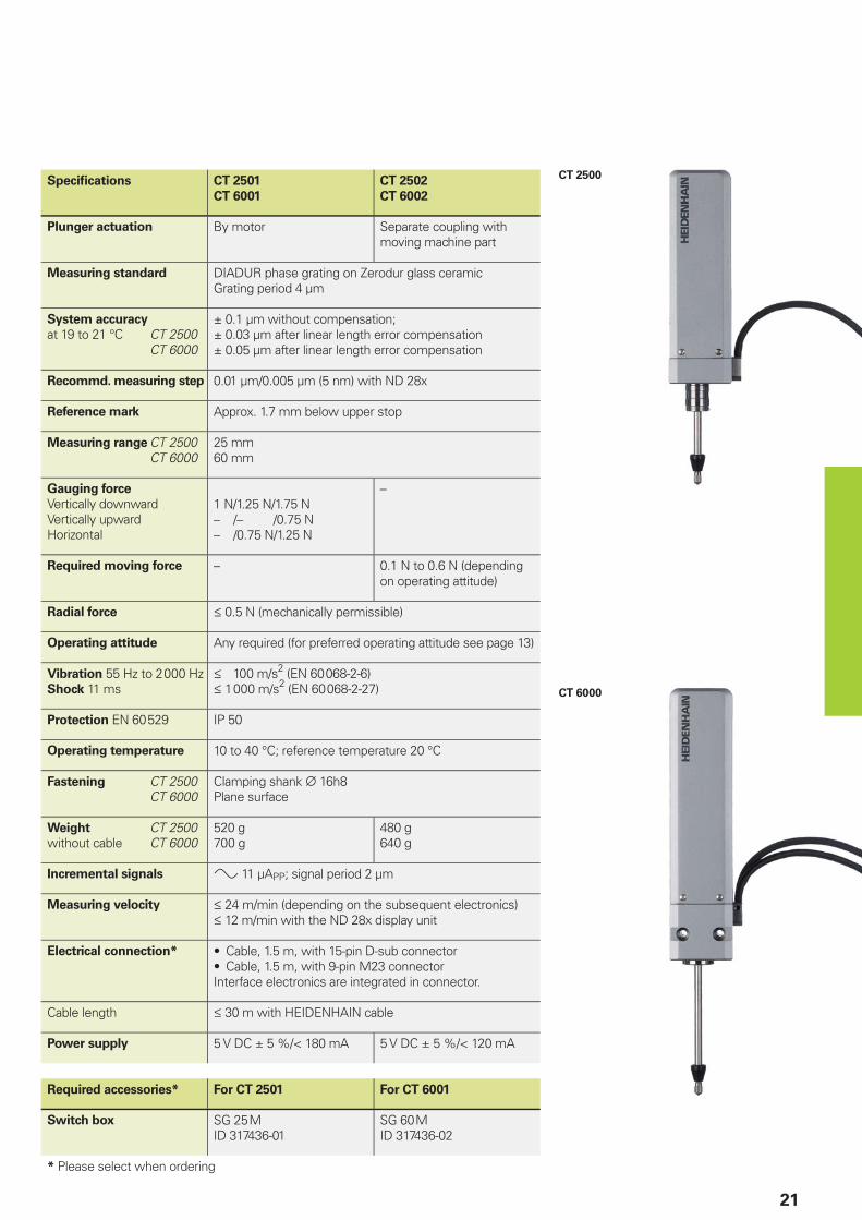
CT 2500
CT 6000
21
Specifi cations CT 2501
CT 6001
CT 2502
CT 6002
Plunger actuation By motor Separate coupling with moving machine part
Measuring standard DIADUR phase grating on Zerodur glass ceramicGrating period 4 µm
System accuracy
at 19 to 21 °C CT 2500 CT 6000
± 0.1 µm without compensation;± 0.03 µm after linear length error compensation± 0.05 µm after linear length error compensation
Recommd. measuring step 0.01 µm/0.005 µm (5 nm) with ND 28x
Reference mark Approx. 1.7 mm below upper stop
Measuring range CT 2500 CT 6000
25 mm60 mm
Gauging force
Vertically downwardVertically upwardHorizontal
1 N/1.25 N/1.75 N– /– /0.75 N– /0.75 N/1.25 N
–
Required moving force – 0.1 N to 0.6 N (depending on operating attitude)
Radial force † 0.5 N (mechanically permissible)
Operating attitude Any required (for preferred operating attitude see page 13)
Vibration 55 Hz to 2 000 HzShock 11 ms
† 100 m/s2 (EN 60 068-2-6)† 1 000 m/s2 (EN 60 068-2-27)
Protection EN 60 529 IP 50
Operating temperature 10 to 40 °C; reference temperature 20 °C
Fastening CT 2500 CT 6000
Clamping shank ¬ 16h8Plane surface
Weight CT 2500without cable CT 6000
520 g700 g
480 g640 g
Incremental signals » 11 µAPP; signal period 2 µm
Measuring velocity † 24 m/min (depending on the subsequent electronics)† 12 m/min with the ND 28x display unit
Electrical connection* Cable, 1.5 m, with 15-pin D-sub connector• Cable, 1.5 m, with 9-pin M23 connector•
Interface electronics are integrated in connector.
Cable length † 30 m with HEIDENHAIN cable
Power supply 5 V DC ± 5 %/< 180 mA 5 V DC ± 5 %/< 120 mA
Required accessories* For CT 2501 For CT 6001
Switch box SG 25 MID 317436-01
SG 60 MID 317436-02
* Please select when ordering

MT 1200
MT 2500
MT 1287
MT 2587
22
HEIDENHAIN-METRO
Length Gauges with ± 0.2 µm AccuracyHigh repeatability•
Plunger actuation by cable release, by the workpiece or pneumatically•
With their high system accuracy and small signal period, the HEIDENHAIN-METRO MT 1200 and MT 2500 length gauges are ideal for precision measuring stations and testing equipment. They feature ball-bush guided plungers and therefore permit high radial forces.
Plunger actuation
The length gauges of the MT 12x1 and MT 25x1 series feature a spring-tensioned plunger that is extended at rest. In a special version without spring it exercises particularly low force on the measured object.
In the pneumatic length gauges MT 1287 and MT 2587, the plunger is retracted to its rest position by the integral spring. It is extended to the measuring position by application of compressed air.
Mounting
The MT 1200 and MT 2500 length gauges are fastened by their 8h6 standard clamping shank. A mounting bracket is available as an accessory to mount the length gauges to plane surfaces or to the MS 200 from HEIDENHAIN.
Output signals
The MT 1200 and MT 2500 length gauges are available with various output signals.
The MT 128x and MT 258x length gauges provide sinusoidal voltage signals with 1 VPP levels, which permit high interpolation.
The MT 1271 and MT 2571 feature integrated digitizing and interpolation electronics with 5-fold or 10-fold interpolation (as ordered) and square-wave signals in TTL levels.
r = Reference mark positions = Beginning of measuring lengthÀ = Air connection for 2 mm tube
MT 12x1 MT 1287
L1 18,5 22,0
L2 10,1 6,2
L3 8,1 4,2
MT 25x1 MT 2587
L1 37,0 41,0
L2 10,1 6,2
L3 8,1 4,2
Mechanical Data
Plunger actuation
Position of plunger at rest
Measuring standard
System accuracy
Reference mark
Measuring range
Gauging force
Version “without spring”Vertically downward
Compressed air
Radial force
Operating attitude
Vibration 55 Hz to 2 000 HzShock 11 ms
Protection EN 60 529
Operating temperature
Fastening
Weight without cable
Electrical Data
For length gauges
Incremental signals*
Signal period
Recommended measuring step
Mech. permissible traversing speed
Edge separation a at scanning frequency*/
traverse speed
200 kHz † 24 m/min 100 kHz † 12 m/min 50 kHz † 6 m/min 25 kHz † 3 m/min
Electrical connection*
(Interface electronics integrated in connector)
Cable length
Power supply
* Please select when ordering
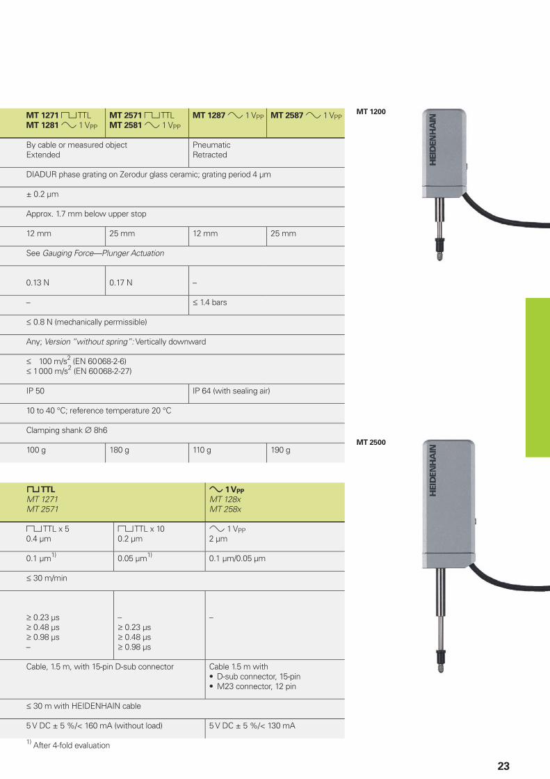
MT 1200
MT 2500
23
MT 1271 « TTLMT 1281 » 1 VPP
MT 2571 « TTLMT 2581 » 1 VPP
MT 1287 » 1 VPP MT 2587 » 1 VPP
By cable or measured objectExtended
PneumaticRetracted
DIADUR phase grating on Zerodur glass ceramic; grating period 4 µm
± 0.2 µm
Approx. 1.7 mm below upper stop
12 mm 25 mm 12 mm 25 mm
See Gauging Force—Plunger Actuation
0.13 N 0.17 N –
– † 1.4 bars
† 0.8 N (mechanically permissible)
Any; Version “without spring”: Vertically downward
† 100 m/s2 (EN 60 068-2-6)† 1 000 m/s2 (EN 60 068-2-27)
IP 50 IP 64 (with sealing air)
10 to 40 °C; reference temperature 20 °C
Clamping shank ¬ 8h6
100 g 180 g 110 g 190 g
« TTL
MT 1271MT 2571
» 1 VPP
MT 128xMT 258x
« TTL x 50.4 µm
« TTL x 100.2 µm
» 1 VPP2 µm
0.1 µm1) 0.05 µm1) 0.1 µm/0.05 µm
† 30 m/min
‡ 0.23 µs‡ 0.48 µs‡ 0.98 µs–
–‡ 0.23 µs‡ 0.48 µs‡ 0.98 µs
–
Cable, 1.5 m, with 15-pin D-sub connector Cable 1.5 m withD-sub connector, 15-pin• M23 connector, 12 pin•
† 30 m with HEIDENHAIN cable
5 V DC ± 5 %/< 160 mA (without load) 5 V DC ± 5 %/< 130 mA
1) After 4-fold evaluation

MT 60
MT 101
24
HEIDENHAIN-METRO
Length Gauges with ± 0.5 µm/± 1 µm AccuracyLarge measuring ranges•
For dimensional and positional measurement•
Large measuring ranges together with their high accuracy make the MT 60 and MT 101 HEIDENHAIN-METRO length gauges attractive for incoming inspection, production monitoring, quality control, or anywhere parts with very different dimensions are measured. But they are also easy to mount as highly accurate position encoders, for example on sliding devices or X-Y tables.
Plunger actuation
M version length gauges feature an integral motor that retracts and extends the plunger. While the MT 101 M operates at a constant gauging force, the MT 60 M allows you to select from three gauging force levels.
K version gauges have no integral plunger actuation. The plunger is freely movable. It can be connected to moving elements such as linear slides and X-Y table by a coupling (see Accessories).
Mounting
The length gauges are mounted onto a fl at surface by two screws. The M versions can also be mounted in the MS 100 and MS 200 gauge stands.
Output signals
The MT 60 and MT 101 provide » 11 µAPP current signals for HEIDENHAIN subsequent electronics.
r = Reference mark position

MT 60 M
MT 101 M
25
Specifi cations MT 60 M
MT 60 K
MT 101 M
MT 101 K
Plunger MT xx Mactuation MT xx K
By motorVia separate coupling with moving machine part
Measuring standard DIADUR grating on silica glass; grating period 10 µm
System accuracy ± 0.5 µm ± 1 µm
Recommd. measuring step 1 µm to 0.1 µm
Reference mark Approx. 1.7 mm from top Approx. 10 mm from top
Measuring range 60 mm 100 mm
Gauging force
Vertically downwardVertically upwardHorizontal
With MT 60 M1 N/1.25 N/1.75 N– /– /0.75 N– /0.75 N/1.25 N
With MT 101 M0.7 N with SG 101 V–0.7 N with SG 101 H
Required moving force
with MT xx K0.1 to 0.6 N (depends on operating attitude)
0.5 to 2 N (depends on operating attitude)
Radial force1) † 0.5 N †2 N
Operating MT xx Mattitude
MT xx K
Any
Any
Vertically downward with SG 101 VHorizontal with SG 101 HAny
Vibration 55 Hz to 2 000 HzShock 11 ms
† 100 m/s2 (EN 60 068-2-6)† 1 000 m/s2 (EN 60 068-2-27)
Protection EN 60 529 IP 50
Operating temperature 10 to 40 °C; reference temperature 20 °C
Fastening Plane surface
Weight MT xx Mwithout cable MT xx K
700 g600 g
1400 g1200 g
Incremental signals » 11 µAPP; signal period 10 µm
Measuring velocity2) † 18 m/min † 60 m/min
Electrical connection*
Cable length
Cable, 1.5 m, with 15-pin D-sub connector;• Cable 1.5 m with 9-pin M23 connector (male);•
† 30 m with HEIDENHAIN cable
Power MT xx Msupply MT xx K Switch box
5 V DC ± 5 %/< 120 mA5 V DC ± 5 %/< 70 mA–
5 V DC ± 5 %/< 70 mA5 V DC ± 5 %/< 70 mAVia power adapter
Required accessories* For MT 60 M For MT 101 M
Switch box SG 60 M Vertical position: SG 101 VHorizontal position: SG 101 H
Power supply unit
100 V AC to 240 V AC– ID 648029-01
* Please select when ordering 2) depending on the subsequent electronics1) Mechanically permissible

ST 12x7
ST 30x7
26
HEIDENHAIN-SPECTO
Length Gauges with ± 1 µm AccuracyVery compact dimensions•
Splash-proof•
Thanks to their very small dimensions, the HEIDENHAIN-SPECTO length gauges are the product of choice for multipoint inspection apparatus and testing equipment.
Plunger actuation
The length gauges of the ST 12x8 and ST 30x8 series feature a spring-tensioned plunger that is extended at rest.
In the pneumatic length gauges ST 12x7 and ST 30x7 the plunger is retracted to its rest position by the integral spring. It is extended to the measuring position by application of compressed air.
Mounting
The HEIDENHAIN-SPECTO length gauges are fastened by their 8h6 standard clamping shank.
Output signals
The HEIDENHAIN-SPECTO length gauges are available with various output signals.
The ST 128x and ST 308x length gauges provide sinusoidal voltage signals with 1 VPP levels, which permit high interpolation.
The ST 127x and ST 307x feature integrated digitizing and interpolation electronics with 5-fold or 10-fold interpolation (as ordered). They are transmitted as square-wave signals in TTL levels.
Mechanical Data
Plunger actuation
Position of plunger at rest
Measuring standard
System accuracy
Reference mark
Measuring range
Gauging force
Compressed air
Radial force
Operating attitude
Vibration 55 Hz to 2 000 HzShock 11 ms
Protection EN 60 529
Operating temperature
Fastening
Weight without cable
Electrical Data
For length gauges
Incremental signals*
Signal period
Recommended measuring step
Mech. permissible traversing speed
Edge separation a at
scanning frequency*/traverse speed
100 kHz † 72 m/min2)
50 kHz † 60 m/min 25 kHz † 30 m/min
Electrical connection*
Cable outlet*
Cable length
Power supply
* Please select when orderingr = Reference mark positions = Beginning of measuring length

ST 1200
ST 3000
27
ST 1278 « TTLST 1288 » 1 VPP
ST 3078 « TTLST 3088 » 1 VPP
ST 1277 « TTLST 1287 » 1 VPP
ST 3077 « TTLST 3087 » 1 VPP
By measured objectExtended
PneumaticRetracted
DIADUR grating on glass; grating period 20 µm
± 1 µm
Approx. 5 mm below upper stop
12 mm 30 mm 12 mm 30 mm
See Gauging Force—Plunger Actuation
– † 2.5 bars
† 0.8 N (mechanically permissible)
Any
† 100 m/s2 (EN 60 068-2-6)† 1 000 m/s2 (EN 60 068-2-27)
IP 64 (for connecting elements see Connecting Elements and Cables)
10 to 40 °C; reference temperature 20 °C
Clamping shank ¬ 8h6
40 g 50 g 40 g 50 g
« TTL
ST 127xST 307x
» 1 VPP
ST 128xST 308x
« TTL x 54 µm
« TTL x 102 µm
» 1 VPP20 µm
1 µm1) 0.5 µm1) 1 µm/0.5 µm
† 72 m/min
‡ 0.48 µs‡ 0.98 µs‡ 1.98 µs
‡ 0.23 µs‡ 0.48 µs‡ 0.98 µs
–
Cable, 1.5 m, with 15-pin D-sub connector(interface electronics integrated)
Cable 1.5 m withD-sub connector, 15-pin• M23 connector, 12 pin•
Axial or radial
† 30 m with HEIDENHAIN cable
5 V DC ± 10 %/< 230 mA (without load) 5 V DC ± 10 %/< 90 mA
1) After 4-fold evaluation2) Mechanically limited

28
Accessories
Measuring Contacts
Ball-type contact
Steel ID 202504-01Carbide ID 202504-02Ruby ID 202504-03
Domed contact
Carbide ID 229232-01
Flat contact
Steel ID 270922-01Carbide ID 202506-01
Pin-type contact
Steel ID 202505-01
Knife-edge contact
Steel ID 202503-01
Roller contact, steelFor a low-friction contact with moving surfaces
Crowned ID 202502-03Cylindrical ID 202502-04
Adjustable contact, carbideFor exact parallel alignment to the measuring plate surface
Flat ID 202507-01Knife-edged ID 202508-01

29
Switch Boxes, Coupling
Switch boxes for CT 2501, CT 6001,
MT 60 M, MT 101 M
Switch boxes are required for length gauges with motorized plunger actuation. The plunger is controlled through two push buttons or by external signal. The gauging force is adjustable at the SG 25 M and SG 60 M switch boxes in three stages.
SG 25 M
ID 317436-01
SG 60 M
ID 317436-02
SG 101 V1)
For the MT 101 M in vertical operationID 361140-01
SG 101 H1)
For the MT 101 M in horizontal operationID 361140-02
Connector (female) 3-pin
For external operation of the switch boxID 340646-05
1) Separate power supply required
Power adapter for SG 101 V/H
An adapter connected to the switch box powers the MT 101 M.
Voltage range 100 to 240 V ACExchangeable plug adapter (U.S. and Euro connectors included in delivery)
ID 648029-01
Coupling
For connecting the plunger of the length gauge (specifi cally for the MT 60 K, MT 101 K, CT 2502 and CT 6002) to a moving machine element
ID 206310-01

30
Accessories for HEIDENHAIN-CERTOGauge Stand
Holder for CS 200
For the CT 2501 with ¬ 16 mm clamping shank
ID 324391-01
No chips or fl aws
CS 200 gauge stand
For length gauges CT 2501* CT 6001
ID 221310-01
Overall height 349 mmBase ¬ 250 mmColumn ¬ 58 mmWeight 15 kg
*) With special holder
The fl atness of the CS 200 is determined with the aid of a Fizeau interferometer.

31
Ceramic Suction Plate, Diaphragm Pump
Ceramic suction plate
Wear-resistant working surface with high surface quality specifi cally for inspecting gauge blocks
ID 223100-01
The gauge block (class 1 or 2)—or any other object with a plane surface—is drawn by suction onto the top of the ceramic plate. The ceramic plate is likewise drawn to the granite base and held in place through negative gauge pressure.
Parts for connecting the ceramic suction plate with the diaphragm pump are among the items supplied:
Pressure tubing 3 mT-jointConnecting piece
Diaphragm pump
Source of suction for drawing the measured object and ceramic suction plate
Power consumption 20 WWeight 2.3 kgLine voltage 230 V AC/50 HzID 754220-01
Line voltage 115 V AC/60 HzID 754220-02

32
Accessories for ACANTO, HEIDENHAIN-METRO and HEIDENHAIN-SPECTO Cable-Type Lifter, Gauge Stands
Cable lifter
For manual plunger actuation of MT 1200 and MT 2500.
The integral pneumatic damping reduces the plunger extension speed to prevent rebounding, for example on very hard materials.
ID 257790-01
MS 200 gauge stand
For length gauges AT1)
ST1)
MT 12001)
MT 25001)
MT 60 M MT 101 M
ID 244154-01
Overall height 346 mmBase ¬ 250 mmColumn ¬ 58 mmWeight 18 kg
1) With special holder
Holder for MS 200
For mounting the length gauges with ¬ 8 mm clamping shank, e.g. AT, ST, MT 1200, MT 2500
ID 324391-02
Clamping sleeve
For length gauges AT, ST MT 1200 MT 2500For fi xing the length gauge reliably without overloading the 8h6 clamping shank.Consisting of:Sleeve, clamping screwID 386811-01 (1 unit per package)ID 386811-02 (10 units per package)

33
MS 45 gauge stand
For length gauges AT, ST MT 1200 MT 2500
ID 202162-02
Overall height 196.5 mmBase ¬ 49 mmColumn ¬ 22 mmWeight 2.2 kg
MS 100 gauge stand
For length gauges AT, ST MT 1200 MT 2500 MT 60 M1)
MT 101 M1)
ID 202164-02
Overall height 385 mmMeasuring plate 100 mm x 115 mmColumn ¬ 50 mmWeight 18 kg
1) With special holder
Holder for MS 100
For mounting the MT 60 MID 207479-01
For mounting the MT 101 MID 206260-01

34
ND 200
Digital readout for one axis
HEIDENHAIN encoders with 11 µAPP or 1 VPP signals and EnDat 2.2 interface can be connected to the digital readouts of the ND 200 series. The ND 280 readout provides the basic functions for simple measuring tasks. The ND 287 also features other functions such as sorting and tolerance check mode, minimum/maximum value storage, measurement series storage. It calculates the mean value and standard deviations and creates histograms and control charts. The ND 287 permits optional connection of a second encoder for sum/difference measurement or of an analog sensor.
The ND 28x units have serial interfaces for measured value transfer.
For more information, see the Digital Readouts/Linear Encoders brochure.
ND 280 ND 287
Encoder input1) 1 x » 11 µAPP, » 1 VPP or EnDat 2.2
Connection D-sub, 15-pin, female
Input frequency » 1 VPP: † 500 kHz; 11 µAPP: † 100 kHz
Signal subdivision Up to 4 096-fold (adjustable)
Display step (adjustable) Linear axis: 0.5 to 0.002 µmAngular axis: 0.5° to 0.000 01° and/or 00°00’00.1”
Functions REF reference mark evaluation• 2 datums•
– Sorting and tolerance checking• Measurement series • (max. 10 000 measured values)Minimum/maximum value storage• Statistics functions• Sum/difference display (option)•
Switching I/O – Yes
Interface RS-232-C/V.24; USB (UART); Ethernet (option for ND 287)
1) Automatic detection of interface
Digital Readouts
ND 2100 G GAGE-CHEK
Input signals* » 1 VPP «TTL EnDat 2.2
Encoder inputs D-sub (15-pin) male D-sub (9-pin) male M12 fl ange socket (8-pin) female
Number of inputs* ND 2104 G: 4ND 2108 G: 8
Signal evaluation/subdivision 10-fold 4-fold –
Display 5.7“ color fl at-panel display
Functions Part programming of up to 100 parts• Sorting and tolerance checking using tolerance and • warning limitsMeasurement series with MIN/MAX display• Mathematical and trigonometric formulas, logical • operationsFunctions for statistical process control (SPC)• Graphic display (measurement results, distribution)• Data storage of values and formulas•
Switching I/O Yes
Interface RS-232-C/V.24• USB•
ND 2100 G GAGE-CHEK
Digital Readouts
The ND 2100 G GAGE-CHEK readouts are versatile metrology displays for measuring and inspection tasks in manufacturing and quality assurance. With inputs for up to eight encoders, they are predestined for multipoint measurements from simple pass/fail detection up to complex SPC evaluation.
For more information see Digital Readouts for Metrology Applications brochure

35
EIB 741
Encoder inputs
switchable» 1 VPP EnDat 2.1 EnDat 2.2
Connection Four D-sub connections (15-pin, female)
Input frequency † 500 kHz –
Signal subdivision 4 096-fold –
Internal memory Typically 250 000 position values per input
Interface Ethernet as per IEEE 802.3 († 1 gigabit)
Driver software and
demo program
For Windows, Linux, LabView
Program examples
EIB 741
External interface box
The EIB 741 is ideal for applications requiring high resolution, fast measured-value acquisition, mobile data acquisition or data storage.
Up to four incremental or absolute HEIDENHAIN encoders can be connected to the EIB 741. The data is output over a standard Ethernet interface.
For more information, see the EIB 741 Product Information sheet.
Evaluation Electronics
MSE 1000
Modular Electronic Unit for Multipoint
Inspection Apparatuses
The MSE 1000 of HEIDENHAIN is a higher level electronics unit in modular design for multipoint inspection apparatuses. The individual modules permit connection of incremental, absolute and analog measurands, the output of switch signals, and communication over diverse interfaces. In all, up to 250 axes or channels can be confi gured. This gives it the fl exibility required to adapt to differing operating conditions.
In its basic confi guration, the MSE 1000 consists of a power module and a basic module. It can be expanded by further modules as needed.
For more information, see the MSE 1000 Product Information sheet.
MSE 1000
Measuring channels/axes Up to 250
Modules Basic Ethernet 10/100 to the PC• Four encoder inputs with EnDat 2.2, TTL or 1 V• PPSwitching input TTL•
Power supply 100 to 240 V AC or 24 V DC
EnDat 4 or 8 EnDat-2.2 encoder inputs
Sinusoidal 4 or 8 encoder inputs with 1 VPP
Square wave 4 or 8 TTL encoder inputs
Analog Two analog inputs
I/O 4 relay outputs and 4 switching inputs TTL
Compressed air Air switch for pneumatic length gauges
Mounting On top hat rail on mounting stand or in electrical cabinets
Software MSEsetup• Ethernet driver•
Interface Standard Ethernet, IEEE 802.3
Sample units immediately available; series production planned for 3rd quarter 2012
Windows is a registered trademark of the Microsoft Corporation.

36
IK 220
Universal PC counter card
The IK 220 is an expansion board for PCs for recording the measured values of two incremental or absolute HEIDENHAIN encoders. The subdivision and counting electronics subdivide the sinusoidal input signals 4 096-fold. A driver software package is included in delivery.
IK 220
Encoder inputs
switchable» 1 VPP » 11 µAPP EnDat 2.1 SSI
Connection Two D-sub connections (15-pin, male)
Input frequency † 500 kHz † 33 kHz –
Signal subdivision 4 096-fold –
Internal memory 8 192 position values per input
Interface PCI bus (plug and play)
Driver software and
demo program
For Windows 2000/XP/Vista/7
in VISUAL C++, VISUAL BASIC and BORLAND DELPHI
For more information, see the IK 220 Product Information sheet.

37
Pin Layout
9-pin
HEIDENHAIN connector
15-pin D-sub connector
For ND 28x/PWM 20 or on encoder
Power supply Incremental signals
3 4
Housing
9 1 2 5 6 7 8
4 2 6 1 9 3 11 14 7
UP 0 V External
shield
Internal
shield
I1 + I1– I2 + I2– I0 + I0–
Brown White – White/Brown
Green Yellow Blue Red Gray Pink
UP = Power supplyVacant pins or wires must not be used!
Shield on housing.Color assignment applies only to extension cable.
Interfaces
Incremental Signals » 11 µAPP
HEIDENHAIN encoders with »11 µAPP interface provide current signals.They are intended for connection to ND position display units or EXE pulse-shaping electronics from HEIDENHAIN.
The sinusoidal incremental signals I1 and I2 are phase-shifted by 90° elec. and have signal levels of approx. 11 µAPP.
The illustrated sequence of output signals—I2 lagging I1—applies for the retracting plunger.
The reference mark signal I0 has a usable component G of approx. 5.5 µA.
The data on signal amplitude apply when the power supply given in the Specifi cations is connected at the encoder. They refer to a differential measurement between the associated outputs. The signal amplitude decreases with increasing frequency. The cutoff frequency indicates the scanning frequency at which a certain percentage of the original signal amplitude is maintained:
–3 dB cutoff frequency:• 70 % of the signal amplitude–6 dB cutoff frequency:• 50 % of the signal amplitude
Interpolation/resolution/measuring step
The output signals of the 11 µAPP interface are usually interpolated in the subsequent electronics in order to attain suffi ciently high resolutions.
Measuring steps for position measurement are recommended in the Specifi cations. For special applications, other resolutions are also possible.
Interface Sinusoidal current signals » 11 µAPP
Incremental signals 2 nearly sinusoidal signals I1 and I2Signal amplitude M: 7 to 16 µAPP/typically 11 µAPPAsymmetry IP – NI/2M: † 0.065Amplitude ratio MA/MB: 0.8 to 1.25Phase angle Iϕ1 + ϕ2I/2: 90° ± 10° elec.
Reference-mark
signal
1 or several signal peaks I0Usable component G: 2 to 8.5 µASwitching threshold E, F: ‡ 0.4 µAZero crossovers K, L: 180° ± 90° elec.
Connecting cable
Cable lengthPropagation time
Shielded HEIDENHAIN cablePUR [3(2 · 0.14 mm2) + (2 · 1 mm2)]Max. 30 m with 90 pF/m distributed capacitance6 ns/m
Signal period360° elec.
(rated value)

38
Signal period360° elec.
(rated value)
A, B, R measured with oscilloscope in differential mode
Cutoff frequency
Typical signal amplitude curve with respect to the scanning frequency
Sig
nal am
plitu
de [
%]
Scanning frequency [kHz]–3 dB cutoff frequency–6 dB cutoff frequency
Interfaces
Incremental Signals » 1 VPP
HEIDENHAIN encoders with »1 VPP interface provide voltage signals that can be highly interpolated.
The sinusoidal incremental signals A and B are phase-shifted by 90° elec. and have amplitudes of typically 1 VPP. The illustrated sequence of output signals—with B lagging A—applies for the direction of motion shown in the dimension drawing.
The reference mark signal R has a usable component G of approx. 0.5 V. Next to the reference mark, the output signal can be reduced by up to 1.7 V to a quiescent value H. This must not cause the subsequent electronics to overdrive. Even at the lowered signal level, signal peaks with the amplitude G can also appear.
The data on signal amplitude apply when the power supply given in the specifi cations is connected to the encoder. They refer to a differential measurement at the 120 ohm terminating resistor between the associated outputs. The signal amplitude decreases with increasing frequency. The cutoff frequency indicates the scanning frequency at which a certain percentage of the original signal amplitude is maintained:
–3 dB • ƒ 70 % of the signal amplitude–6 dB • ƒ 50 % of the signal amplitude
The data in the signal description apply to motions at up to 20% of the –3 dB-cutoff frequency.
Interpolation/resolution/measuring step
The output signals of the 1 VPP interface are usually interpolated in the subsequent electronics in order to attain suffi ciently high resolutions. For velocity control, interpolation factors are commonly over 1000 in order to receive usable velocity information even at low speeds.
Measuring steps for position measurement are recommended in the specifi cations. For special applications, other resolutions are also possible.
Short-circuit stability
A temporary short circuit of one signal output to 0 V or UP (except encoders with UPmin= 3.6 V) does not cause encoder failure, but it is not a permissible operating condition.
Short circuit at 20 °C 125 °C
One output < 3 min < 1 min
All outputs < 20 s < 5 s
Interface Sinusoidal voltage signals » 1 VPP
Incremental signals 2 nearly sinusoidal signals A and B
Signal amplitude M: 0.6 to 1.2 VPP; typically 1 VPPAsymmetry |P – N|/2M: † 0.065Amplitude ratio MA/MB: 0.8 to 1.25Phase angle Iϕ1 + ϕ2I/2: 90° ± 10° elec.
Reference-mark
signal
One or several signal peaks R
Usable component G: ‡ 0.2 VQuiescent value H: † 1.7 VSwitching threshold E, F: 0.04 to 0.68 VZero crossovers K, L: 180° ± 90° elec.
Connecting cable
Cable lengthPropagation time
Shielded HEIDENHAIN cablePUR [4(2 x 0.14 mm2) + (4 x 0.5 mm2)]Max. 150 m at 90 pF/m distributed capacitance6 ns/m
These values can be used for dimensioning of the subsequent electronics. Any limited tolerances in the encoders are listed in the specifi cations. For encoders without integral bearing, reduced tolerances are recommended for initial operation (see the mounting instructions).
Alternative signal shape

39
Input Circuitry of
the Subsequent Electronics
Dimensioning
Operational amplifi er MC 34074Z0 = 120 −R1 = 10 k− and C1 = 100 pFR2 = 34.8 k− and C2 = 10 pFUB = ±15 VU1 approx. U0
–3 dB cutoff frequency of circuitry
Approx. 450 kHzApprox. 50 kHz with C1 = 1000 pF and C2 = 82 pFThe circuit variant for 50 kHz does reduce the bandwidth of the circuit, but in doing so it improves its noise immunity.
Circuit output signals
Ua = 3.48 VPP typicallyGain 3.48
Monitoring of the incremental signals
The following thresholds are recommended for monitoring of the signal level M:Lower threshold: 0.30 VPPUpper threshold: 1.35 VPP
Incremental signals
Reference-mark signal
Ra < 100 −, typically 24 −Ca < 50 pFΣIa < 1 mAU0 = 2.5 V ± 0.5 V(relative to 0 V of the power supply)
Encoder Subsequent electronics
Pin Layout
12-pin coupling, M23 12-pin connector, M23 15-pin D-sub connector
For ND 28x/PWM 20 or on encoder
Power supply Incremental signals Other signals
12 2 10 11 5 6 8 1 3 4 9 7 /
4 12 2 10 1 9 3 11 14 7 5/6/8/15 13 /
UP Sensor
UP
0 V Sensor
0 VA+ A– B+ B– R+ R– Vacant Vacant Vacant
Brown/Green
Blue White/Green
White Brown Green Gray Pink Red Black / Violet Yellow
Shield on housing; UP = power supply voltageSensor: The sensor line is connected in the encoder with the corresponding power line.Vacant pins or wires must not be used!Color assignment applies only to extension cable.

40
Interfaces
Incremental Signals « TTL
HEIDENHAIN encoders with « TTL interface incorporate electronics that digitize sinusoidal scanning signals with or without interpolation.
The incremental signals are transmitted as the square-wave pulse trains Ua1 and Ua2, phase-shifted by 90° elec. The reference
mark signal consists of one or more reference pulses Ua0, which are gated with the incremental signals. In addition, the integrated electronics produce their inverted
signals , £ and ¤ for noise-proof transmission. The illustrated sequence of output signals—with Ua2 lagging Ua1—applies to the direction of motion shown in the dimension drawing.
The fault-detection signal ¥ indicates fault conditions such as breakage of the power line or failure of the light source. It can be used for such purposes as machine shut-off during automated production.
The distance between two successive edges of the incremental signals Ua1 and Ua2 through 1-fold, 2-fold or 4-fold evaluation is one measuring step.
The subsequent electronics must be designed to detect each edge of the square-wave pulse. The minimum edge
separation a listed in the Specifi cations applies for the illustrated input circuitry with a cable length of 1 m, and refers to measurement at the output of the differential line receiver. Cable-dependent differences in the propagation times additionally reduce the edge separation by 0.2 ns per meter of cable. To prevent counting errors, design the subsequent electronics to process as little as 90 % of the resulting edge separation.
The max. permissible shaft speed or traversing velocity must never be exceeded.
The permissible cable length for transmission of the TTL square-wave signals to the subsequent electronics depends on the edge separation a. It is at most 100 m, or 50 m for the fault detection signal. This requires, however, that the power supply (see Specifi cations) be ensured at the encoder. The sensor lines can be used to measure the voltage at the encoder and, if required, correct it with an automatic control system (remote sense power supply).
Interface Square-wave signals « TTL
Incremental signals 2 square-wave signals Ua1, Ua2 and their inverted signals ,£
Reference-mark
signal
Pulse widthDelay time
1 or more TTL square-wave pulses Ua0 and their inverted pulses ¤ 90° elec. (other widths available on request)|td| † 50 ns
Fault-detection
signal
Pulse width
1 TTL square-wave pulse ¥ Improper function: LOW (upon request: Ua1/Ua2 high impedance)Proper function: HIGHtS ‡ 20 ms
Signal amplitude Differential line driver as per EIA standard RS-422UH ‡ 2.5 V at –IH = 20 mA ERN 1x23: 10 mAUL † 0.5 V at IL = 20 mA ERN 1x23: 10 mA
Permissible load Z0 ‡ 100 − Between associated outputs|IL| † 20 mA Max. load per output (ERN 1x23: 10 mA)Cload † 1000 pF With respect to 0 VOutputs protected against short circuit to 0 V
Switching times
(10% to 90%)t+ / t– † 30 ns (typically 10 ns)with 1 m cable and recommended input circuitry
Connecting cable
Cable lengthPropagation time
Shielded HEIDENHAIN cablePUR [4(2 × 0.14 mm2) + (4 × 0.5 mm2)]Max. 100 m (¥ max. 50 m) at distributed capacitance 90 pF/m6 ns/m
Signal period 360° elec. Fault
Measuring step after
4-fold evaluation
Inverse signals , £, ¤ are not shown
Permissible
cable length
with respect to the edge separation
Cab
le len
gth
[m
]
Edge separation [µs]
Without ¥
With ¥

41
Pin Layout
15-pin
D-sub connector
12-pin
HEIDENHAIN
connector
Power supply Incremental signals Other signals
12 2 10 11 5 6 8 1 3 4 7 / 9
4 12 2 10 1 9 3 11 14 7 13 5/6/8 15
UP Sensor
UP
0 V Sensor
0 VUa1 Ua2 £ Ua0 ¤ ¥1)
Vacant Vacant2)
Brown/Green
Blue White/Green
White Brown Green Gray Pink Red Black Violet – Yellow
Shield on housing; UP = power supply voltageSensor: The sensor line is connected in the encoder with the corresponding power line.1) ERO 14xx: Vacant 2) Exposed linear encoders: Switchover TTL/11 µAPP for PWTVacant pins or wires must not be used!Color assignment applies only to extension cable.
Input Circuitry of
the Subsequent Electronics
Dimensioning
IC1 = Recommended differential line receiver
DS 26 C 32 AT Only for a > 0.1 µs: AM 26 LS 32 MC 3486 SN 75 ALS 193
R1 = 4.7 k−R2 = 1.8 k−Z0 = 120 −C1 = 220 pF (serves to improve
noise immunity)
Incremental signals
Reference-mark signal
Fault-detection signal
Encoder Subsequent electronics

42
Interfaces
Absolute Position Values
Interface EnDat serial bidirectional
Data transfer Absolute position values, parameters and additional information
Data input Differential line receiver according to EIA standard RS 485 for the signals CLOCK, CLOCK, DATA and DATA
Data output Differential line driver according to EIA standard RS 485 for DATA and DATA signals.
Position values Ascending during traverse in direction of arrow (see dimensions of the encoders)
Incremental signals » 1 VPP (see Incremental signals 1 VPP) depending on the unit
The EnDat interface is a digital, bidirectional interface for encoders. It is capable both of transmitting position values as well as transmitting or updating information stored in the encoder, or saving new information. Thanks to the serial transmission method, only four signal lines are required. The data is transmitted in synchronism with the clock signal from the subsequent electronics. The type of transmission (position values, parameters, diagnostics, etc.) is selected through mode commands that the subsequent electronics send to the encoder. Some functions are available only with EnDat 2.2 mode commands.
For more information, refer to the EnDat Technical Information sheet or visit www.endat.de.
Position values can be transmitted with or without additional information (e.g. position value 2, temperature sensors, diagnostics, limit position signals).
Besides the position, additional information can be interrogated in the closed loop and functions can be performed with the EnDat 2.2 interface.
Parameters are saved in various memory areas, e.g.:
Encoder-specifi c information• Information of the OEM (e.g. “electronic • ID label” of the motor)Operating parameters (datum shift, • instruction, etc.)Operating status (alarm or warning • messages)
Monitoring and diagnostic functions of the EnDat interface make a detailed inspection of the encoder possible.
Error messages• Warnings• Online diagnostics based on valuation • numbers (EnDat 2.2)
Incremental signals
EnDat encoders are available with or without incremental signals. EnDat 21 and EnDat 22 encoders feature a high internal resolution. An evaluation of the incremental signal is therefore unnecessary.
Clock frequency and cable length
The clock frequency is variable—depending on the cable length (max. 150 m)—between 100 kHz and 2 MHz. With propagation-delay compensation in the subsequent electronics, clock frequencies up to 16 MHz at cable lengths up to 100 m are possible (for other values see Specifi cations).
Ordering
designation
Command set Incremental
signals
Power supply
EnDat 01 EnDat 2.1 or EnDat 2.2
With See specifi cations of the encoder
EnDat 21 Without
EnDat 02 EnDat 2.2 With Expanded range3.6 to 5.25 V DCor 14 V DCEnDat 22 EnDat 2.2 Without
Versions of the EnDat interface (bold print indicates standard versions)
Cab
le len
gth
[m
]
Clock frequency [kHz]
EnDat 2.1; EnDat 2.2 without propagation-delay compensation
EnDat 2.2 with propagation-delay compensation
Absolute encoder Subsequent electronics
» 1 VPP A*)
» 1 VPP B*)
Operating parameters
Operating status
Parameters of the OEM
Parameters of the encoder manufacturer for
EnDat 2.1 EnDat 2.2
*) Depends on encoder
Absolute position value En
Dat
inte
rfac
e
Incremental signals *)

43
Input Circuitry of Subsequent
Electronics
Dimensioning
IC1 = RS 485 differential line receiver and driver
C3 = 330 pFZ0 = 120 −
Data transfer
Incremental signals
Depending on encoder
Encoder Subsequent electronics
1 VPP
Pin Layout
8-pin coupling, M12 15-pin D-sub connector, male
For IK215/PWM 20
Power supply Absolute position values
8 2 5 1 3 4 7 6
4 12 2 10 5 13 8 15
UP Sensor UP 0 V Sensor 0 V DATA DATA CLOCK CLOCK
Brown/Green Blue White/Green White Gray Pink Violet Yellow

M23
M23
M23
M23
M23
44
The pins on connectors are numbered in the direction opposite to those on couplings or fl ange sockets, regardless of whether the connecting elements are
male or
female contacts.
When engaged, the connections are protected to IP 67 (D-sub connector: IP 50; EN 60 529). When not engaged, there is no protection.
Cables and Connecting Elements
General Information
Connector (insulated): A connecting element with a coupling ring. Available with male or female contacts.
Symbols
Coupling insulated: Connecting element with external thread; available with male or female contacts.
Symbols
D-sub connector: for HEIDENHAIN controls, counters and IK absolute value cards
Symbols
Accessories for fl ange sockets and
M23 mounted couplings
Bell seal
ID 266526-01
Threaded metal dust cap
ID 219926-01
Flange socket: Permanently mounted on the encoder or a housing, with external thread (like a coupling), available with male or female contacts.
Symbols
Mounted coupling
with central fastening
Mounted coupling
with fl ange
Cutout for mounting
1) With integrated interpolation electronics

45
12-pin 9-pin
Mating element on connecting cable to
connector on encoder cable
Coupling (female) for cable ¬ 8 mm
291698-02 291698-01
Connector on connecting cable for connection to subsequent electronics
Connector (male) For cable with ¬ 8 mm
291697-08 291697-04
Coupling on connecting cable Coupling (male) for cable ¬ 8 mm
291698-04 291698-24
Flange socket for mounting on subsequent electronics
Flange socket (female)
315892-08 315892-06
Mounted couplings
With fl ange (female) ¬ 8 mm
291698-07 291698-06
With fl ange (male) ¬ 8 mm
291698-31 –
With central fastener (male) ¬ 6 to 10 mm
741045-01 –
Adapter » 1 VPP/11 µAPP
For converting the 1 VPP signals to 11 µAPP; 12-pin M23 connector (female) and 9-pin M23 connector (male)
364914-01 –
Connecting Elements
15-pin
Connector on connecting cable to
connector on encoder cable
D-sub connector, female for cable ¬ 8 mm 315650-14

46
Connecting Cables 1 VPP, TTL, 11 µAPP 12-Pin 9-Pin M23 M23
1 VPP, TTL 11 µAPP
PUR connecting cable [3(2 x 0.14 mm2) + (2 x 1 mm2)]
PUR connecting cable [6(2 x 0.19 mm2)]
PUR connecting cable [4(2 x 0.14 mm2) + (4 x 0.5 mm2)] ¬ 8 mm ¬ 6 mm1) ¬ 8 mm
Complete with D-sub connector (female) and M23 connector (male)
331693-xx 355215-xx –
With one D-sub connector (female),15-pin
332433-xx 355209-xx –
Complete with D-sub connector (female) and connector (male), 15-pin for ND 28x, EIB 741; only 1 VPP: ND 11xx, ND 12xx
335074-xx 355186-xx 738681-xx
Complete with D-sub connector (female) and D-sub connector (female), 15-pin,for ND 780, PT 880, IK 220
335077-xx 349687-xx –
Cable only 244957-01 291639-01 –
Complete
with M23 coupling (female) and D-sub connector (male), 15-pin for ND 28x, EIB 741; only 1 VPP: ND 11xx, ND 12xx
309784-xx – 653231-xx
Complete
with M23 coupling (female) and D-sub connector (male), 19-pin for ND 11xx, ND 12xx (not 1 VPP)
617513-xx – 716905-xx
Complete
with M23 coupling (female) and D-sub connector (female), 15-pin,for ND 780, PT 880, IK 220
309783-xx – 368172-xx
With one connector
with M23 coupling (female)298402-xx – 309780-xx
Complete
with M23 coupling (female) and M23 connector (male)
298400-xx – 309774-xx
1) Cable length max. 9 m

47
EnDat without incremental signals
PUR connecting cable [4 × 2 × 0.09 mm2]
PUR connecting cable [(4 × 0.14 mm2) + (4 × 0.34 mm2)] ¬ 6 mm ¬ 3.7 mm
Complete with connector (female) and coupling (male)
368330-xx 801142-xx1)
Complete with right-angle connector (female) and coupling (male)
373289-xx 801149-xx1)
Complete with connector (female) and D-sub connector (female), 15-pin, for TNC (position inputs)
535627-xx –
Complete with connector (female) and D-sub connector (male), 15-pin, for IK 215, PWM 20, EIB 741 etc.
524599-xx 801129-xx1)
Complete with right-angle connector (female) and D-sub connector (male), 15-pin, for IK 215, PWM 20, EIB 741 etc.
722025-xx 801140-xx1)
With one connector (female) 634265-xx –
With one right-angle connector, (female) 606317-xx –
1) Max. cable length 6 m
Connecting Cables EnDat 8-Pin M12

48
General Electrical Information
Power supply
Connect HEIDENHAIN encoders only to subsequent electronics whose power supply is generated from PELV systems (EN 50 178). In addition, overcurrent protection and overvoltage protection are required in safety-related applications.
If HEIDENHAIN encoders are to be operated in accordance with IEC 61010-1, power must be supplied from a secondary circuit with current or power limitation as per IEC 61010-1:2001, section 9.3 or IEC 60950-1:2005, section 2.5 or a Class 2 secondary circuit as specifi ed in UL1310.
The encoders require a stabilized DC
voltage UP as power supply. The respective Specifi cations state the required power supply and the current consumption. The permissible ripple content of the DC voltage is:
High frequency interference• UPP < 250 mV with dU/dt > 5 V/µsLow frequency fundamental ripple• UPP < 100 mV
The values apply as measured at the encoder, i.e., without cable infl uences. The voltage can be monitored and adjusted with the encoder’s sensor lines. If a controllable power supply is not available, the voltage drop can be halved by switching the sensor lines parallel to the corresponding power lines.
Calculation of the voltage drop:
¹U = 2 · 10–3 ·
where ¹U: Voltage drop in V 1.05: Length factor due to
twisted wires LC: Cable length in m I: Current consumption
in mA AP: Cross section of power
lines in mm2
The voltage actually applied to the encoder is to be considered when calculating the
encoder’s power requirement. This voltage consists of the supply voltage UP provided by the subsequent electronics minus the line drop at the encoder. For encoders with an expanded supply range, the voltage drop in the power lines must be calculated under consideration of the nonlinear current consumption (see next page).
Transient response of supply voltage and switch-on/switch-off behavior
Output signals invalid InvalidValid
UPP
1.05 · LC · I56 · AP
If the voltage drop is known, all parameters for the encoder and subsequent electronics can be calculated, e.g. voltage at the encoder, current requirements and power consumption of the encoder, as well as the power to be provided by the subsequent electronics.
Switch-on/off behavior of the encoders
The output signals are valid no sooner than after the switch-on time tSOT = 1.3 s (2 s for PROFIBUS-DP) (see diagram). During the time tSOT they can have any levels up to 5.5 V (with HTL encoders up to UPmax). If an interpolation electronics unit is inserted between the encoder and the power supply, this unit’s switch-on/off characteristics must also be considered. If the power supply is switched off, or when the supply voltage falls below Umin, the output signals are also invalid. During restart, the signal
level must remain below 1 V for the time tSOT before power on. These data apply to the encoders listed in the catalog—customer-specifi c interfaces are not included.
Encoders with new features and increased performance range may take longer to switch on (longer time tSOT). If you are responsible for developing subsequent electronics, please contact HEIDENHAIN in good time.
Insulation
The encoder housings are isolated against internal circuits.
Rated surge voltage: 500 V (preferred value as per VDE 0110 Part 1, overvoltage category II, contamination level 2)
Cable Cross section of power supply lines AP
1 VPP/TTL/HTL 11 µAPP EnDat/SSI
17-pinEnDat
5)
8-pin
¬ 3.7 mm 0.05 mm2 – – 0.09 mm2
¬ 4.3 mm 0.24 mm2 – – –
¬ 4.5 mm EPG 0.05 mm2 – 0.05 mm2 0.09 mm2
¬ 4.5 mm
¬ 5.1 mm
0.14/0.092) mm2
0.052), 3) mm20.05 mm2 0.05/0.146) mm2 0.14 mm2
¬ 5.5 mm PVC 0.1 mm2 – – –
¬ 6 mm
¬ 10 mm1)
0.19/0.142), 4) mm2 – 0.08/0.196) mm2 0.34 mm2
¬ 8 mm
¬ 14 mm1)
0.5 mm2 1 mm2 0.5 mm2 1 mm2
1) Metal armor 2) Rotary encoders 3) Length gauges4) LIDA 400 5) Also Fanuc, Mitsubishi 6) RCN, LC adapter cable

49
Encoders with expanded supply
voltage range
For encoders with expanded supply voltage range, the current consumption has a nonlinear relationship with the supply voltage. On the other hand, the power consumption follows a linear curve (see Current and power consumption diagram). The maximum power consumption at minimum and maximum supply voltage is listed in the Specifi cations. The maximum power consumption (worst case) accounts for:
Recommended receiver circuit• Cable length 1 m• Age and temperature infl uences• Proper use of the encoder with respect • to clock frequency and cycle time
The typical current consumption at no load (only supply voltage is connected) for 5 V supply is specifi ed.
The actual power consumption of the encoder and the required power output of the subsequent electronics are measured, while taking the voltage drop on the supply lines into consideration, in four steps:
Step 1: Resistance of the supply lines
The resistance values of the supply lines (adapter cable and encoder cable) can be calculated with the following formula:
RL = 2 ·
Step 2: Coeffi cients for calculation of
the drop in line voltage
b = –RL · – UP
c = PEmin · RL + · RL · (UP – UEmin)
Step 3: Voltage drop based on the
coeffi cients b and c
¹U = –0.5 · (b + ¹b2 – 4 · c)
Step 4: Parameters for subsequent
electronics and the encoder
Voltage at encoder:UE = UP – ¹U
Current requirement of encoder:IE = ¹U / RL
Power consumption of encoder:PE = UE · IE
Power output of subsequent electronics:PS = UP · IE
1.05 · LC56 · AP
Supply voltage [V]
Supply voltage [V]
Po
wer
ou
tpu
t o
f su
bseq
uen
t
ele
ctr
on
ics (
no
rmalized
)
Encoder cable/adapter cable TotalConnecting cable
Po
wer
co
nsu
mp
tio
n o
r cu
rren
t
req
uir
em
en
t (n
orm
alized
)
Power consumption of encoder(normalized to value at 5 V)
Current requirement of encoder(normalized to value at 5 V)
Where:UEmax,UEmin: Minimum or maximum supply
voltage of the encoder in VPEmin,PEmax: Maximum power consumption at
minimum or maximum power supply, respectively, in W
UP: Supply voltage of the subsequent electronics in V
RL: Cable resistance (for both directions) in ohms
¹U: Voltage drop in the cable in V1.05: Length factor due to twisted wiresLC: Cable length in mAP: Cross section of power lines
in mm2
Infl uence of cable length on the power output of the subsequent electronics (example representation)
Current and power consumption with respect to the supply voltage (example representation)
PEmax – PEminUEmax – UEmin
PEmax – PEminUEmax – UEmin

50
Rigid confi guration
Frequent fl exing
Frequent fl exing
Cable Bend radius R
Rigid confi guration Frequent fl exing
¬ 3.7 mm ‡ 8 mm ‡ 40 mm
¬ 4.3 mm ‡ 10 mm ‡ 50 mm
¬ 4.5 mm EPG ‡ 18 mm –
¬ 4.5 mm
¬ 5.1 mm
¬ 5.5 mm PVC
‡ 10 mm ‡ 50 mm
¬ 6 mm
¬ 10 mm1)
‡ 20 mm‡ 35 mm
‡ 75 mm‡ 75 mm
¬ 8 mm
¬ 14 mm1)
‡ 40 mm‡ 100 mm
‡ 100 mm‡ 100 mm
1) Metal armor
Cable
For safety-related applications, use HEIDENHAIN cables and connectors.
Versions
The cables of almost all HEIDENHAIN encoders and all adapter and connecting cables are sheathed in polyurethane (PUR
cables). Many adapter cables for within motors and a few cables on encoders are sheathed in a special elastomer (EPG). Many adapter cables within the motor consist of TPE wires (special thermoplastic) in braided sleeving. Individual encoders feature cable with a sleeve of polyvinyl
chloride (PVC). This cables are identifi ed in the catalog as EPG, TPE or PVC.
Durability
PUR cables are resistant to oil in accordance with VDE 0472 (Part 803/test type B) and to hydrolysis and microbes in accordance with VDE 0282 (Part 10). They are free of PVC and silicone and comply with UL safety directives. The UL certifi cation “AWM STYLE 20963 80 °C 30 V E63216” is documented on the cable.
EPG cables are resistant to oil in accordance with VDE 0472 (Part 803/test type B) and to hydrolysis in accordance with VDE 0282 (Part 10). They are free of silicone and halogens. In comparison with PUR cables, they are only somewhat resistant to media, frequent fl exing and continuous torsion.
PVC cables are oil resistant. The UL certifi -cation “AWM E64638 STYLE20789 105C VW-1SC NIKKO” is documented on the cable.
TPE wires with braided sleeving are oil resistant and highly fl exible.
Temperature range
Rigid confi guration
Frequent fl exing
PUR –40 to 80 °C –10 to 80 °C
EPGTPE
–40 to 120 °C –
PVC –20 to 90 °C –10 to 90 °C
PUR cables with limited resistance to hydrolysis and microbes are rated for up to 100 °C. If needed, please ask for assistance from HEIDENHAIN Traunreut.
Lengths
The cable lengths listed in the Specifi cations apply only for HEIDENHAIN cables and the recommended input circuitry of subsequent electronics.
Electrically Permissible Speed/
Traversing Speed
The maximum permissible shaft speed or traversing velocity of an encoder is derived from
the • mechanically permissible shaft speed/traversing velocity (if listed in the Specifi cations) andthe • electrically permissible shaft speed/traversing velocity.
For encoders with sinusoidal output
signals, the electrically permissible shaft speed/traversing velocity is limited by the –3 dB/ –6 dB cutoff frequency or the permissible input frequency of the subsequent electronics.
For encoders with square-wave signals, the electrically permissible shaft speed/ traversing velocity is limited by – the maximum permissible scanning/
output frequency fmax of the encoder, and
– the minimum permissible edge separation a for the subsequent electronics.
For angle or rotary encoders
nmax = fmaxz
· 60 · 103
For linear encoders
vmax = fmax · SP · 60 · 10–3
Where: nmax: Elec. permissible speed in min–1
vmax: Elec. permissible traversing velocity in m/min
fmax: Max. scanning/output frequency of encoder or input frequency of subsequent electronics in kHz
z: Line count of the angle or rotary encoder per 360°
SP: Signal period of the linear encoder in µm

51
Noise-Free Signal Transmission
Electromagnetic compatibility/
CE-compliance
When properly installed, and when HEIDENHAIN connecting cables and cable assemblies are used, HEIDENHAIN encoders fulfi ll the requirements for electromagnetic compatibility according to 2004/108/EC with respect to the generic standards for:
Noise immunity EN 61 000-6-2:•
Specifi cally: – ESD EN 61 000-4-2 – Electromagnetic fi elds EN 61 000-4-3 – Burst EN 61 000-4-4 – Surge EN 61 000-4-5 – Conducted disturbances EN 61 000-4-6 – Power frequency
magnetic fi elds EN 61 000-4-8 – Pulse magnetic fi elds EN 61 000-4-9
Interference EN 61 000-6-4:•
Specifi cally: – For industrial, scientifi c and medical
equipment (ISM) EN 55 011 – For information technology
equipment EN 55 022
Connect the housings of the encoder, • connecting elements and subsequent electronics through the shield of the cable. Ensure that the shield has complete contact over the entire surface (360°). For encoders with more than one electrical connection, refer to the documentation for the respective product.For cables with multiple shields, the • inner shields must be routed separately from the outer shield. Connect the inner shield to 0 V of the subsequent electronics. Do not connect the inner shields with the outer shield, neither in the encoder nor in the cable.Connect the shield to protective ground • as per the mounting instructions.Prevent contact of the shield (e.g. • connector housing) with other metal surfaces. Pay attention to this when installing cables.Do not install signal cables in the direct • vicinity of interference sources (inductive consumers such as contactors, motors, frequency inverters, solenoids, etc.).– Suffi cient decoupling from
interference-signal-conducting cables can usually be achieved by an air clearance of 100 mm or, when cables are in metal ducts, by a grounded partition.
– A minimum spacing of 200 mm to inductors in switch-mode power supplies is required.
If compensating currents are to be • expected within the overall system, a separate equipotential bonding conductor must be provided. The shield does not have the function of an equipotential bonding conductor.Provide power only from PELV systems • (EN 50 178) to position encoders. Provide high-frequency grounding with low impedance (EN 60 204-1 Chap. EMC).
For encoders with 11 µA• PP interface: For extension cables, use only HEIDENHAIN cable ID 244955-01. Overall length: max. 30 m.
Transmission of measuring signals—
electrical noise immunity
Noise voltages arise mainly through capacitive or inductive transfer. Electrical noise can be introduced into the system over signal lines and input or output terminals.Possible sources of noise include:
Strong magnetic fi elds from transformers, • brakes and electric motorsRelays, contactors and solenoid valves• High-frequency equipment, pulse • devices, and stray magnetic fi elds from switch-mode power suppliesAC power lines and supply lines to the • above devices
Protection against electrical noise
The following measures must be taken to ensure disturbance-free operation:
Use only original HEIDENHAIN cables. • Consider the voltage drop on supply lines.Use connecting elements (such as • connectors or terminal boxes) with metal housings. Only the signals and power supply of the connected encoder may be routed through these elements. Applications in which additional signals are sent through the connecting element require specifi c measures regarding electrical safety and EMC.
Minimum distance from sources of interference

NO HEIDENHAIN Scandinavia AB7300 Orkanger, Norwaywww.heidenhain.no
PH Machinebanks` CorporationQuezon City, Philippines 1113E-mail: [email protected]
PL APS02-489 Warszawa, Polandwww.apserwis.com.pl
PT FARRESA ELECTRÓNICA, LDA.4470 - 177 Maia, Portugalwww.farresa.pt
RO HEIDENHAIN Reprezentanta RomaniaBrasov, 500338, Romaniawww.heidenhain.ro
RS Serbia − BG
RU OOO HEIDENHAIN125315 Moscow, Russiawww.heidenhain.ru
SE HEIDENHAIN Scandinavia AB12739 Skärholmen, Swedenwww.heidenhain.se
SG HEIDENHAIN PACIFIC PTE LTD.Singapore 408593www.heidenhain.com.sg
SK KOPRETINA TN s.r.o.91101 Trencin, Slovakiawww.kopretina.sk
SL Posredništvo HEIDENHAINNAVO d.o.o.2000 Maribor, Sloveniawww.heidenhain-hubl.si
TH HEIDENHAIN (THAILAND) LTDBangkok 10250, Thailandwww.heidenhain.co.th
TR T&M Mühendislik San. ve Tic. LTD. STI·.
34728 Ümraniye-Istanbul, Turkeywww.heidenhain.com.tr
TW HEIDENHAIN Co., Ltd.Taichung 40768, Taiwan R.O.C.www.heidenhain.com.tw
UA Gertner Service GmbH Büro Kiev 01133 Kiev, Ukrainewww.gertnergroup.com
US HEIDENHAIN CORPORATIONSchaumburg, IL 60173-5337, USAwww.heidenhain.com
VE Maquinaria Diekmann S.A. Caracas, 1040-A, VenezuelaE-mail: [email protected]
VN AMS Co. LtdHCM City, VietnamE-mail: [email protected]
ZA MAFEMA SALES SERVICES C.C.Midrand 1685, South Africawww.heidenhain.co.za
DK TP TEKNIK A/S2670 Greve, Denmarkwww.tp-gruppen.dk
ES FARRESA ELECTRONICA S.A.08028 Barcelona, Spainwww.farresa.es
FI HEIDENHAIN Scandinavia AB02770 Espoo, Finlandwww.heidenhain.fi
FR HEIDENHAIN FRANCE sarl92310 Sèvres, Francewww.heidenhain.fr
GB HEIDENHAIN (G.B.) LimitedBurgess Hill RH15 9RD, United Kingdomwww.heidenhain.co.uk
GR MB Milionis Vassilis17341 Athens, Greecewww.heidenhain.gr
HK HEIDENHAIN LTDKowloon, Hong KongE-mail: [email protected]
HR Croatia − SL
HU HEIDENHAIN Kereskedelmi Képviselet1239 Budapest, Hungarywww.heidenhain.hu
ID PT Servitama Era ToolsindoJakarta 13930, IndonesiaE-mail: [email protected]
IL NEUMO VARGUS MARKETING LTD.Tel Aviv 61570, IsraelE-mail: [email protected]
IN HEIDENHAIN Optics & ElectronicsIndia Private LimitedChetpet, Chennai 600 031, Indiawww.heidenhain.in
IT HEIDENHAIN ITALIANA S.r.l.20128 Milano, Italywww.heidenhain.it
JP HEIDENHAIN K.K.Tokyo 102-0083, Japanwww.heidenhain.co.jp
KR HEIDENHAIN Korea LTD.Gasan-Dong, Seoul, Korea 153-782www.heidenhain.co.kr
ME Montenegro − SL
MK Macedonia − BG
MX HEIDENHAIN CORPORATION MEXICO20235 Aguascalientes, Ags., MexicoE-mail: [email protected]
MY ISOSERVE Sdn. Bhd56100 Kuala Lumpur, MalaysiaE-mail: [email protected]
NL HEIDENHAIN NEDERLAND B.V.6716 BM Ede, Netherlandswww.heidenhain.nl
AR NAKASE SRL.B1653AOX Villa Ballester, Argentinawww.heidenhain.com.ar
AT HEIDENHAIN Techn. Büro Österreich83301 Traunreut, Germanywww.heidenhain.de
AU FCR Motion Technology Pty. LtdLaverton North 3026, AustraliaE-mail: [email protected]
BA Bosnia and Herzegovina − SL
BE HEIDENHAIN NV/SA1760 Roosdaal, Belgiumwww.heidenhain.be
BG ESD Bulgaria Ltd.Sofi a 1172, Bulgariawww.esd.bg
BR DIADUR Indústria e Comércio Ltda.04763-070 – São Paulo – SP, Brazilwww.heidenhain.com.br
BY BelarusGERTNER Service GmbH50354 Huerth, Germanywww.gertnergroup.com
CA HEIDENHAIN CORPORATIONMississauga, OntarioL5T2N2, Canadawww.heidenhain.com
CH HEIDENHAIN (SCHWEIZ) AG8603 Schwerzenbach, Switzerlandwww.heidenhain.ch
CN DR. JOHANNES HEIDENHAIN (CHINA) Co., Ltd.Beijing 101312, Chinawww.heidenhain.com.cn
CZ HEIDENHAIN s.r.o.102 00 Praha 10, Czech Republicwww.heidenhain.cz
DE HEIDENHAIN Vertrieb Deutschland83301 Traunreut, Deutschland{ 08669 31-3132| 08669 32-3132E-Mail: [email protected]
HEIDENHAIN Technisches Büro Nord12681 Berlin, Deutschland{ 030 54705-240
HEIDENHAIN Technisches Büro Mitte08468 Heinsdorfergrund, Deutschland{ 03765 69544
HEIDENHAIN Technisches Büro West44379 Dortmund, Deutschland{ 0231 618083-0
HEIDENHAIN Technisches Büro Südwest70771 Leinfelden-Echterdingen, Deutschland{ 0711 993395-0
HEIDENHAIN Technisches Büro Südost83301 Traunreut, Deutschland{ 08669 31-1345
Vollständige und weitere Adressen siehe www.heidenhain.deFor complete and further addresses see www.heidenhain.de
Zu
m A
bh
eft
en
hie
r fa
lzen
! /
Fo
ld h
ere
fo
r fi
lin
g!
������������ ��� ��������������� ��������������������������������������� �������������� ������������������ ��!�"����������
������ !���� ��!�
208945-29 · 15 · 3/2012 · F&W · Printed in Germany